Avaya Bcm50 Users Manual
2015-06-01
: Avaya Avaya-Bcm50-Users-Manual-736309 avaya-bcm50-users-manual-736309 avaya pdf
Open the PDF directly: View PDF ![]() .
.
Page Count: 1
- Task List
- Contents
- Getting started with BCM50
- Overview of BCM50 Administration
- BCM50 Management Environment
- BCM50 web page
- BCM50 Management Environment and Applications
- Managing BCM50 with Element Manager
- Managing BCM50 with Telset administration
- Managing BCM50 Voicemail and ContactCenter: CallPilot Manager
- Managing Digital Mobility
- Programming telephone sets: Desktop Assistant portfolio
- Performing initialization: Startup Profile
- Monitoring BCM50: BCM Monitor
- Managing BCM50 remotely with SNMP
- Element Manager
- BCM50 feature licensing
- BCM50 Help system
- BCM50 common file input/output processes
- BCM50 Security Fundamentals
- BCM50 Security Policies
- Security Policies panel
- Configuring system security policies
- Entry Policy tab
- Local Authentication Policy tab
- Authentication Service Policy tab
- Session Management Policy tab
- SSL and SSH Policy tab
- Setting system access control policies
- Setting credential complexity
- Setting lockout policy for failed logins
- Setting password expiry policy
- Setting password history policy
- Setting the authentication method
- Configuring an authentication server
- Setting the idle session timeout
- Uploading a Web Server Certificate
- Transferring an SSH Key-Pair
- Managing BCM50 Accounts and Privileges
- Managing user accounts and user groups
- Accounts and Privileges panel
- Configuring user accounts, user groups and privileges
- Adding a new user account
- Modifying a user account
- Adding callback for a dial-up user
- Adding NAT rules for a dial-up user
- Adding Telset access for a user
- Deleting a user account
- Changing a user’s password
- Changing the current user’s password
- Creating a group
- Deleting a group
- Modifying group privileges
- Adding a user account to a group
- Deleting a user account from a group
- Re-enable a locked-out user
- Enabling and disabling an account
- Enabling and disabling exclusive access
- Using the BCM50 Hardware Inventory
- Managing BCM50 with SNMP
- Using the BCM50 Fault Management System
- Using the BCM50 Service Management System
- Monitoring BCM50 System Metrics
- Monitoring BCM50 Telephony Metrics
- Telephony Metrics
- Activity Reporter Basic
- Trunk Module Metrics
- Viewing Performance History information
- Viewing D-Channel information
- Disabling or enabling a B channel setting
- Provisioning a PRI B-channel
- Trunk Module CSU statistics
- Enabling the internal CSU
- Checking trunk module alarms
- CbC limit metrics
- Hunt Group Metrics
- PSTN Fallback Metrics
- Proactive Voice Quality Management
- Telephony Metrics
- BCM50 Utilities
- Backing Up and Restoring BCM50 Data
- Managing BCM50 Logs
- Accounting Management
- Managing BCM50 Software Updates
- Management Information Bases
- List of BCM50 alarms
- Index

BCM50 3.0
Business Communications Manager
Document Status:Standard
Document Number: NN40020-600
Document Version: 02.03
Date: January 2010
BCM50 Administration Guide
Copyright © 2007-2010 Nortel Networks, All Rights Reserved
All rights reserved.
The information in this document is subject to change without notice. The statements, configurations, technical data, and
recommendations in this document are believed to be accurate and reliable, but are presented without express or implied
warranty. Users must take full responsibility for their applications of any products specified in this document. The
information in this document is proprietary to Nortel Networks.
Trademarks
Nortel, the Nortel logo, and the Globemark are trademarks of Nortel Networks.
Microsoft, MS, MS-DOS, Windows, and Windows NT are trademarks of Microsoft Corporation.
All other trademarks and registered trademarks are the property of their respective owners.

3
BCM50 Administration Guide
Task List
Getting started with BCM50 . . . . . . . . . . . . . . . . . . . . . . . . . . . . . . . . . . . . . 15
Overview of BCM50 Administration . . . . . . . . . . . . . . . . . . . . . . . . . . . . . . 23
BCM50 Management Environment . . . . . . . . . . . . . . . . . . . . . . . . . . . . . . . 31
BCM50 Security Fundamentals . . . . . . . . . . . . . . . . . . . . . . . . . . . . . . . . . . 73
BCM50 Security Policies . . . . . . . . . . . . . . . . . . . . . . . . . . . . . . . . . . . . . . . 79
To set system access control policies ...........................................................................85
To set credential complexity ..........................................................................................85
To set lockout policy for failed logins.............................................................................86
To set password expiry policy .......................................................................................87
To set password history.................................................................................................87
To set the authentication method ..................................................................................88
To configure an authentication server in Element Manager ..........................................88
To set the idle session timeout ......................................................................................92
To upload a Web Server Certificate ..............................................................................92
To transfer an SSH Key-Pair .........................................................................................93
Managing BCM50 Accounts and Privileges . . . . . . . . . . . . . . . . . . . . . . . . 95
To add a new user account .........................................................................................119
To modify a user account ............................................................................................120
To add callback for a dial-up user ...............................................................................120
To add NAT rules for a dial-up user ............................................................................121
To add Telset access for a user ..................................................................................121
To delete a user account .............................................................................................122
To change a user’s password......................................................................................122
To change the current user’s password ......................................................................122
To create a group ........................................................................................................123
To delete a group ........................................................................................................123
To modify group privileges ..........................................................................................124
To add a user account to a group................................................................................124
To delete a user account from a group........................................................................124
To release a locked-out user .......................................................................................125
To enable or disable an account immediately .............................................................126
To enable or disable an account on a timed basis ......................................................126
To enable/disable exclusive access ............................................................................127
Using the BCM50 Hardware Inventory . . . . . . . . . . . . . . . . . . . . . . . . . . . 129
To view or update information about the BCM50 main chassis ..................................130
To view or update BCM50 system expansion information ..........................................132
To view or update other information about the BCM50 main unit ...............................133
To view information about attached devices ...............................................................134
To view additional information about the BCM50 hardware inventory ........................136
Managing BCM50 with SNMP . . . . . . . . . . . . . . . . . . . . . . . . . . . . . . . . . . . 137

4Task List
NN40020-600
To configure the BCM50 SNMP agent ........................................................................140
To configure BCM50 SNMP settings...........................................................................140
To add an SNMP manager to the BCM50 SNMP manager list...................................141
To delete an SNMP manager ......................................................................................142
To delete a community string value.............................................................................143
To add a service access point .....................................................................................144
To view details associated with a service access point...............................................145
To delete a service access point .................................................................................145
To modify a trap destination ........................................................................................147
Using the BCM50 Fault Management System . . . . . . . . . . . . . . . . . . . . . 149
To view an alarm .........................................................................................................153
To acknowledge an alarm ...........................................................................................153
To clear the alarm log..................................................................................................154
To include or omit acknowledged alarms in the Alarm Banner ...................................156
To specify the alarm set ..............................................................................................157
To clear an alarm from the alarm set...........................................................................157
To reset the Status LED ..............................................................................................158
To enable or disable SNMP traps for alarms...............................................................159
To enable or disable viewing of selected alarms in the Alarms table ..........................159
To view settings for the alarm set................................................................................159
To test an alarm...........................................................................................................160
Using the BCM50 Service Management System . . . . . . . . . . . . . . . . . . . 161
To view details about services.....................................................................................163
To restart a service......................................................................................................164
Monitoring BCM50 System Metrics . . . . . . . . . . . . . . . . . . . . . . . . . . . . . . 165
To configure monitoring mode.....................................................................................166
To configure logging attributes ....................................................................................167
To view the QoS monitoring information .....................................................................168
To refresh the QoS monitor data .................................................................................168
To access UPS Status.................................................................................................169
To access the NTP Metrics .........................................................................................169
Monitoring BCM50 Telephony Metrics . . . . . . . . . . . . . . . . . . . . . . . . . . . 171
To enable Activity Reporter Basic ...............................................................................172
To disable Activity Reporter Basic...............................................................................172
To view Trunk Module status.......................................................................................172
To disable or enable a B channel setting ....................................................................174
To provision a PRI B-channel......................................................................................175
To enable the internal CSU .........................................................................................176
To check the performance statistics ............................................................................176
To check the CSU alarms............................................................................................177
To check carrier failure alarms ....................................................................................177
To check bipolar violations ..........................................................................................177
To check short-term alarms.........................................................................................178
To check defects .........................................................................................................178
To view CSU Alarm History .........................................................................................178
To access the CbC limit metrics ..................................................................................179
To access the Hunt Group metrics ..............................................................................181
To access PSTN Fallback metrics...............................................................................182

Task List 5
BCM50 Administration Guide
To configure PVQM threshold settings........................................................................184
To access PVQM metrics ............................................................................................187
BCM50 Utilities . . . . . . . . . . . . . . . . . . . . . . . . . . . . . . . . . . . . . . . . . . . . . . 191
To install BCM Monitor separately from BCM50 Element Manager ............................192
To remove BCM Monitor .............................................................................................192
To start BCM Monitor without the Element Manager...................................................193
To start BCM Monitor from the Element Manager.......................................................193
To connect to a different BCM50.................................................................................193
To configure static snapshot settings ..........................................................................194
To save a static snapshot............................................................................................196
To configure dynamic snapshot settings .....................................................................197
To disable monitoring of UIP messages......................................................................204
To log UIP data............................................................................................................204
To view UIP log files ....................................................................................................205
To configure timeout settings ......................................................................................205
To expand a UIP message ..........................................................................................206
To clear UIP message details......................................................................................206
To view all lines ...........................................................................................................207
To view the date and time of minimum and maximum values.....................................210
To reset the minimum and maximum values for a statistic..........................................210
To ping a device ..........................................................................................................211
To perform a trace route..............................................................................................212
To view Ethernet activity..............................................................................................213
To reboot the BCM50 ..................................................................................................214
To perform a warm reset of BCM50 telephony services .............................................214
To perform a cold reset of BCM50 telephony services................................................215
To set Release Reasons .............................................................................................215
Backing Up and Restoring BCM50 Data . . . . . . . . . . . . . . . . . . . . . . . . . . 217
To perform an immediate backup to the BCM50.........................................................221
To perform an immediate backup to your personal computer .....................................222
To perform an immediate backup to a network folder .................................................223
To perform an immediate backup to a USB storage device ........................................224
To perform an immediate backup to an FTP server ....................................................224
To perform an immediate backup to an SFTP server..................................................225
To view scheduled backups ........................................................................................227
To perform a scheduled backup to the BCM50 ...........................................................227
To perform a scheduled backup to a network folder ...................................................228
To perform a scheduled backup to a USB storage device ..........................................230
To perform a scheduled backup to an FTP server ......................................................231
To perform a scheduled backup to an SFTP server....................................................232
To modify a scheduled backup....................................................................................233
To delete a backup schedule.......................................................................................234
To restore data from the BCM50 .................................................................................237
To restore data from your personal computer .............................................................237
To restore data from a network folder .........................................................................238
To restore data from a USB storage device ................................................................240
To restore data from an FTP server ............................................................................241
To restore data from an SFTP server..........................................................................242
To restore the factory configuration.............................................................................243

6Task List
NN40020-600
Managing BCM50 Logs . . . . . . . . . . . . . . . . . . . . . . . . . . . . . . . . . . . . . . . . 245
To perform an immediate log transfer to a USB storage device..................................249
To perform an immediate log transfer to your personal computer...............................249
To perform an immediate log transfer to a network folder...........................................250
To perform an immediate log transfer to an FTP server..............................................251
To perform an immediate log transfer to an SFTP server ...........................................252
To perform a scheduled log transfer to a storage location ..........................................253
To modify a scheduled log transfer .............................................................................254
To delete a scheduled log transfer ..............................................................................255
To use the BCM50 Web Page to transfer log files to other destinations .....................256
To extract log files using the Element Manager ..........................................................257
To specify retrieval criteria...........................................................................................259
To filter information in the Retrieval Results table .......................................................260
To view log details for multiple log records..................................................................260
Accounting Management . . . . . . . . . . . . . . . . . . . . . . . . . . . . . . . . . . . . . . 263
Managing BCM50 Software Updates . . . . . . . . . . . . . . . . . . . . . . . . . . . . . 265
To obtain updates from the Nortel Technical Support Web page................................265
To view details about software updates in progress....................................................267
To apply an update from your personal computer.......................................................269
To apply a software update from a USB storage device .............................................270
To apply an update from a network folder ...................................................................271
To apply an update from an FTP server......................................................................272
To apply an update from an HTTP server ...................................................................273
To create a scheduled software update ......................................................................276
To modify a scheduled software update......................................................................277
To delete a scheduled software update.......................................................................278
To view the software update history ............................................................................278
To remove a software update......................................................................................279
To view the BCM50 software inventory .......................................................................280
Management Information Bases . . . . . . . . . . . . . . . . . . . . . . . . . . . . . . . . 281
To access MIB files from the BCM50 Web Page ........................................................283
To access MIB files from the Nortel Customer Service Site........................................283
List of BCM50 alarms . . . . . . . . . . . . . . . . . . . . . . . . . . . . . . . . . . . . . . . . . 287

7
BCM50 Administration Guide
Contents
Chapter 1
Getting started with BCM50 . . . . . . . . . . . . . . . . . . . . . . . . . . . . . . . . . . . . . 15
About this guide . . . . . . . . . . . . . . . . . . . . . . . . . . . . . . . . . . . . . . . . . . . . . . . . . . . . . . 15
Purpose . . . . . . . . . . . . . . . . . . . . . . . . . . . . . . . . . . . . . . . . . . . . . . . . . . . . . . . . . 15
Organization . . . . . . . . . . . . . . . . . . . . . . . . . . . . . . . . . . . . . . . . . . . . . . . . . . . . . 15
Audience . . . . . . . . . . . . . . . . . . . . . . . . . . . . . . . . . . . . . . . . . . . . . . . . . . . . . . . . . . . 17
Acronyms . . . . . . . . . . . . . . . . . . . . . . . . . . . . . . . . . . . . . . . . . . . . . . . . . . . . . . . . . . . 17
Symbols and conventions used in this guide . . . . . . . . . . . . . . . . . . . . . . . . . . . . . . . . 19
Related publications . . . . . . . . . . . . . . . . . . . . . . . . . . . . . . . . . . . . . . . . . . . . . . . . . . 20
How to get Help . . . . . . . . . . . . . . . . . . . . . . . . . . . . . . . . . . . . . . . . . . . . . . . . . . . . . . 21
Chapter 2
Overview of BCM50 Administration . . . . . . . . . . . . . . . . . . . . . . . . . . . . . . . 23
About BCM50 . . . . . . . . . . . . . . . . . . . . . . . . . . . . . . . . . . . . . . . . . . . . . . . . . . . . . . . 23
BCM50 hardware . . . . . . . . . . . . . . . . . . . . . . . . . . . . . . . . . . . . . . . . . . . . . . . . . 23
BCM50 applications . . . . . . . . . . . . . . . . . . . . . . . . . . . . . . . . . . . . . . . . . . . . . . . 25
Management Model . . . . . . . . . . . . . . . . . . . . . . . . . . . . . . . . . . . . . . . . . . . . . . . . . . . 25
BCM50 interfaces . . . . . . . . . . . . . . . . . . . . . . . . . . . . . . . . . . . . . . . . . . . . . . . . . . . . 28
LAN . . . . . . . . . . . . . . . . . . . . . . . . . . . . . . . . . . . . . . . . . . . . . . . . . . . . . . . . . . . . 28
WAN . . . . . . . . . . . . . . . . . . . . . . . . . . . . . . . . . . . . . . . . . . . . . . . . . . . . . . . . . . . 29
Protocols . . . . . . . . . . . . . . . . . . . . . . . . . . . . . . . . . . . . . . . . . . . . . . . . . . . . . . . . 29
Chapter 3
BCM50 Management Environment . . . . . . . . . . . . . . . . . . . . . . . . . . . . . . . . 31
BCM50 web page . . . . . . . . . . . . . . . . . . . . . . . . . . . . . . . . . . . . . . . . . . . . . . . . . . . . 31
BCM50 Management Environment and Applications . . . . . . . . . . . . . . . . . . . . . . . . . 33
Managing BCM50 with Element Manager . . . . . . . . . . . . . . . . . . . . . . . . . . . . . . . 34
Managing BCM50 with Telset administration . . . . . . . . . . . . . . . . . . . . . . . . . . . . 34
Managing BCM50 Voicemail and ContactCenter: CallPilot Manager . . . . . . . . . . 34
Managing Digital Mobility . . . . . . . . . . . . . . . . . . . . . . . . . . . . . . . . . . . . . . . . . . . 34
Programming telephone sets: Desktop Assistant portfolio . . . . . . . . . . . . . . . . . . 35
Performing initialization: Startup Profile . . . . . . . . . . . . . . . . . . . . . . . . . . . . . . . . 35
Monitoring BCM50: BCM Monitor . . . . . . . . . . . . . . . . . . . . . . . . . . . . . . . . . . . . . 36
Managing BCM50 remotely with SNMP . . . . . . . . . . . . . . . . . . . . . . . . . . . . . . . . 36
Element Manager . . . . . . . . . . . . . . . . . . . . . . . . . . . . . . . . . . . . . . . . . . . . . . . . . . . . 36
Element Manager setup . . . . . . . . . . . . . . . . . . . . . . . . . . . . . . . . . . . . . . . . . . . . 37
Element Manager window attributes . . . . . . . . . . . . . . . . . . . . . . . . . . . . . . . . . . . 42
Element Manager panels . . . . . . . . . . . . . . . . . . . . . . . . . . . . . . . . . . . . . . . . . . . 51
Effective use of Element Manager . . . . . . . . . . . . . . . . . . . . . . . . . . . . . . . . . . . . 52

8Contents
NN40020-600NN40020-600
Element Manager data features . . . . . . . . . . . . . . . . . . . . . . . . . . . . . . . . . . . . . . 53
Element Manager application logging . . . . . . . . . . . . . . . . . . . . . . . . . . . . . . . . . . 63
BCM50 integrated launch of related applications . . . . . . . . . . . . . . . . . . . . . . . . . 64
BCM50 feature licensing . . . . . . . . . . . . . . . . . . . . . . . . . . . . . . . . . . . . . . . . . . . . . . . 65
BCM50 Help system . . . . . . . . . . . . . . . . . . . . . . . . . . . . . . . . . . . . . . . . . . . . . . . . . . 66
Menu bar Help . . . . . . . . . . . . . . . . . . . . . . . . . . . . . . . . . . . . . . . . . . . . . . . . . . . . 66
Field-level Help . . . . . . . . . . . . . . . . . . . . . . . . . . . . . . . . . . . . . . . . . . . . . . . . . . . 67
Context-sensitive Help . . . . . . . . . . . . . . . . . . . . . . . . . . . . . . . . . . . . . . . . . . . . . 68
BCM50 common file input/output processes . . . . . . . . . . . . . . . . . . . . . . . . . . . . . . . . 68
Comparison of data repositories . . . . . . . . . . . . . . . . . . . . . . . . . . . . . . . . . . . . . . 69
Chapter 4
BCM50 Security Fundamentals . . . . . . . . . . . . . . . . . . . . . . . . . . . . . . . . . . 73
System security considerations . . . . . . . . . . . . . . . . . . . . . . . . . . . . . . . . . . . . . . . 73
Secure network protocols and encryption . . . . . . . . . . . . . . . . . . . . . . . . . . . . . . . 74
Security audits . . . . . . . . . . . . . . . . . . . . . . . . . . . . . . . . . . . . . . . . . . . . . . . . . . . . 75
Firewalls . . . . . . . . . . . . . . . . . . . . . . . . . . . . . . . . . . . . . . . . . . . . . . . . . . . . . . . . 75
Security certificate . . . . . . . . . . . . . . . . . . . . . . . . . . . . . . . . . . . . . . . . . . . . . . . . . 76
Site authentication . . . . . . . . . . . . . . . . . . . . . . . . . . . . . . . . . . . . . . . . . . . . . . . . . 76
Additional security capabilities . . . . . . . . . . . . . . . . . . . . . . . . . . . . . . . . . . . . . . . 77
Chapter 5
BCM50 Security Policies . . . . . . . . . . . . . . . . . . . . . . . . . . . . . . . . . . . . . . . . 79
Security Policies panel . . . . . . . . . . . . . . . . . . . . . . . . . . . . . . . . . . . . . . . . . . . . . . . . 79
Configuring system security policies . . . . . . . . . . . . . . . . . . . . . . . . . . . . . . . . . . . . . . 84
Entry Policy tab . . . . . . . . . . . . . . . . . . . . . . . . . . . . . . . . . . . . . . . . . . . . . . . . . . . 84
Local Authentication Policy tab . . . . . . . . . . . . . . . . . . . . . . . . . . . . . . . . . . . . . . . 84
Authentication Service Policy tab . . . . . . . . . . . . . . . . . . . . . . . . . . . . . . . . . . . . . 84
Session Management Policy tab . . . . . . . . . . . . . . . . . . . . . . . . . . . . . . . . . . . . . . 84
SSL and SSH Policy tab . . . . . . . . . . . . . . . . . . . . . . . . . . . . . . . . . . . . . . . . . . . . 85
Setting system access control policies . . . . . . . . . . . . . . . . . . . . . . . . . . . . . . . . . 85
Setting credential complexity . . . . . . . . . . . . . . . . . . . . . . . . . . . . . . . . . . . . . . . . 85
Setting lockout policy for failed logins . . . . . . . . . . . . . . . . . . . . . . . . . . . . . . . . . . 86
Setting password expiry policy . . . . . . . . . . . . . . . . . . . . . . . . . . . . . . . . . . . . . . . 87
Setting password history policy . . . . . . . . . . . . . . . . . . . . . . . . . . . . . . . . . . . . . . . 87
Setting the authentication method . . . . . . . . . . . . . . . . . . . . . . . . . . . . . . . . . . . . . 87
Configuring an authentication server . . . . . . . . . . . . . . . . . . . . . . . . . . . . . . . . . . 88
Setting the idle session timeout . . . . . . . . . . . . . . . . . . . . . . . . . . . . . . . . . . . . . . 92
Uploading a Web Server Certificate . . . . . . . . . . . . . . . . . . . . . . . . . . . . . . . . . . . 92
Transferring an SSH Key-Pair . . . . . . . . . . . . . . . . . . . . . . . . . . . . . . . . . . . . . . . . 93

Contents 9
BCM50 Administration Guide
Chapter 6
Managing BCM50 Accounts and Privileges . . . . . . . . . . . . . . . . . . . . . . . . 95
Managing user accounts and user groups . . . . . . . . . . . . . . . . . . . . . . . . . . . . . . . . . 95
User accounts . . . . . . . . . . . . . . . . . . . . . . . . . . . . . . . . . . . . . . . . . . . . . . . . . . . . 95
Default passwords . . . . . . . . . . . . . . . . . . . . . . . . . . . . . . . . . . . . . . . . . . . . . . . . . 97
Default groups . . . . . . . . . . . . . . . . . . . . . . . . . . . . . . . . . . . . . . . . . . . . . . . . . . . . 97
Default access privileges excluding set-based privileges . . . . . . . . . . . . . . . . . . . 99
Telset access security . . . . . . . . . . . . . . . . . . . . . . . . . . . . . . . . . . . . . . . . . . . . . 107
Telset group access privileges . . . . . . . . . . . . . . . . . . . . . . . . . . . . . . . . . . . . . . 108
Blocking user accounts . . . . . . . . . . . . . . . . . . . . . . . . . . . . . . . . . . . . . . . . . . . . 108
Accounts and Privileges panel . . . . . . . . . . . . . . . . . . . . . . . . . . . . . . . . . . . . . . . . . 109
Current Account . . . . . . . . . . . . . . . . . . . . . . . . . . . . . . . . . . . . . . . . . . . . . . . . . 109
View by Accounts . . . . . . . . . . . . . . . . . . . . . . . . . . . . . . . . . . . . . . . . . . . . . . . . 112
View by Account: General . . . . . . . . . . . . . . . . . . . . . . . . . . . . . . . . . . . . . . . . . . 113
View by Account: Remote Access . . . . . . . . . . . . . . . . . . . . . . . . . . . . . . . . . . . 114
View by Account: History . . . . . . . . . . . . . . . . . . . . . . . . . . . . . . . . . . . . . . . . . . 115
View by Account: Group Membership . . . . . . . . . . . . . . . . . . . . . . . . . . . . . . . . . 115
View by Groups . . . . . . . . . . . . . . . . . . . . . . . . . . . . . . . . . . . . . . . . . . . . . . . . . . 116
View by Groups: General . . . . . . . . . . . . . . . . . . . . . . . . . . . . . . . . . . . . . . . . . . 116
View by Groups: Members . . . . . . . . . . . . . . . . . . . . . . . . . . . . . . . . . . . . . . . . . 118
Configuring user accounts, user groups and privileges . . . . . . . . . . . . . . . . . . . . . . . 118
Adding a new user account . . . . . . . . . . . . . . . . . . . . . . . . . . . . . . . . . . . . . . . . . 119
Modifying a user account . . . . . . . . . . . . . . . . . . . . . . . . . . . . . . . . . . . . . . . . . . 119
Adding callback for a dial-up user . . . . . . . . . . . . . . . . . . . . . . . . . . . . . . . . . . . . 120
Adding NAT rules for a dial-up user . . . . . . . . . . . . . . . . . . . . . . . . . . . . . . . . . . 120
Adding Telset access for a user . . . . . . . . . . . . . . . . . . . . . . . . . . . . . . . . . . . . . 121
Deleting a user account . . . . . . . . . . . . . . . . . . . . . . . . . . . . . . . . . . . . . . . . . . . 121
Changing a user’s password . . . . . . . . . . . . . . . . . . . . . . . . . . . . . . . . . . . . . . . . 122
Changing the current user’s password . . . . . . . . . . . . . . . . . . . . . . . . . . . . . . . . 122
Creating a group . . . . . . . . . . . . . . . . . . . . . . . . . . . . . . . . . . . . . . . . . . . . . . . . . 123
Deleting a group . . . . . . . . . . . . . . . . . . . . . . . . . . . . . . . . . . . . . . . . . . . . . . . . . 123
Modifying group privileges . . . . . . . . . . . . . . . . . . . . . . . . . . . . . . . . . . . . . . . . . 123
Adding a user account to a group . . . . . . . . . . . . . . . . . . . . . . . . . . . . . . . . . . . . 124
Deleting a user account from a group . . . . . . . . . . . . . . . . . . . . . . . . . . . . . . . . . 124
Re-enable a locked-out user . . . . . . . . . . . . . . . . . . . . . . . . . . . . . . . . . . . . . . . . 125
Enabling and disabling an account . . . . . . . . . . . . . . . . . . . . . . . . . . . . . . . . . . . 126
Enabling and disabling exclusive access . . . . . . . . . . . . . . . . . . . . . . . . . . . . . . 127
Chapter 7
Using the BCM50 Hardware Inventory . . . . . . . . . . . . . . . . . . . . . . . . . . . . 129
About the BCM50 Hardware Inventory . . . . . . . . . . . . . . . . . . . . . . . . . . . . . . . . . . . 129
Viewing and updating information about the BCM50 system . . . . . . . . . . . . . . . . . . 130

10 Contents
NN40020-600NN40020-600
Viewing and updating information about the BCM50 main unit . . . . . . . . . . . . . 130
Viewing and updating BCM50 system expansion information . . . . . . . . . . . . . . 131
Viewing and updating other information about the BCM50 system . . . . . . . . . . 132
Viewing information about devices . . . . . . . . . . . . . . . . . . . . . . . . . . . . . . . . . . . . . . 133
Viewing additional information about the BCM50 hardware inventory . . . . . . . . . . . 134
. . . . . . . . . . . . . . . . . . . . . . . . . . . . . . . . . . . . . . . . . . . . . . . . . . . . . . . . . . . . . . . . . . 136
Chapter 8
Managing BCM50 with SNMP . . . . . . . . . . . . . . . . . . . . . . . . . . . . . . . . . . . 137
Overview of BCM50 support for SNMP . . . . . . . . . . . . . . . . . . . . . . . . . . . . . . . . . . . 137
Configuring routers to use Element Manager with SNMP . . . . . . . . . . . . . . . . . . . . . 138
Configuring SNMP settings . . . . . . . . . . . . . . . . . . . . . . . . . . . . . . . . . . . . . . . . . . . . 139
Configuring general SNMP settings . . . . . . . . . . . . . . . . . . . . . . . . . . . . . . . . . . 139
Configuring SNMP community strings . . . . . . . . . . . . . . . . . . . . . . . . . . . . . . . . 142
Configuring service access points . . . . . . . . . . . . . . . . . . . . . . . . . . . . . . . . . . . . 144
Configuring SNMP trap destinations . . . . . . . . . . . . . . . . . . . . . . . . . . . . . . . . . 145
Viewing and modifying SNMP trap destinations . . . . . . . . . . . . . . . . . . . . . . . . . . . . 147
Auto-SNMP dial-out . . . . . . . . . . . . . . . . . . . . . . . . . . . . . . . . . . . . . . . . . . . . . . . . . . 148
Alarm severity levels . . . . . . . . . . . . . . . . . . . . . . . . . . . . . . . . . . . . . . . . . . . . . . . . . 148
Chapter 9
Using the BCM50 Fault Management System . . . . . . . . . . . . . . . . . . . . . . 149
Overview of BCM50 fault management . . . . . . . . . . . . . . . . . . . . . . . . . . . . . . . . . . . 149
About BCM50 alarms . . . . . . . . . . . . . . . . . . . . . . . . . . . . . . . . . . . . . . . . . . . . . . . . 150
Alarms and log files . . . . . . . . . . . . . . . . . . . . . . . . . . . . . . . . . . . . . . . . . . . . . . . . . . 151
Alarm severities . . . . . . . . . . . . . . . . . . . . . . . . . . . . . . . . . . . . . . . . . . . . . . . . . . . . . 151
Administering alarms . . . . . . . . . . . . . . . . . . . . . . . . . . . . . . . . . . . . . . . . . . . . . . . . . 152
Using the Alarms Panel . . . . . . . . . . . . . . . . . . . . . . . . . . . . . . . . . . . . . . . . . . . . 152
Using the Alarm Banner . . . . . . . . . . . . . . . . . . . . . . . . . . . . . . . . . . . . . . . . . . . 154
Using the alarm set . . . . . . . . . . . . . . . . . . . . . . . . . . . . . . . . . . . . . . . . . . . . . . . 156
Alarms and LEDs . . . . . . . . . . . . . . . . . . . . . . . . . . . . . . . . . . . . . . . . . . . . . . . . . . . . 157
Using SNMP traps . . . . . . . . . . . . . . . . . . . . . . . . . . . . . . . . . . . . . . . . . . . . . . . . . . . 158
Configuring alarm settings . . . . . . . . . . . . . . . . . . . . . . . . . . . . . . . . . . . . . . . . . . . . . 158
Chapter 10
Using the BCM50 Service Management System . . . . . . . . . . . . . . . . . . . . 161
Overview of the BCM50 service management system . . . . . . . . . . . . . . . . . . . . . . . 161
BCM50 services . . . . . . . . . . . . . . . . . . . . . . . . . . . . . . . . . . . . . . . . . . . . . . . . . . . . 161
Starting, stopping, and restarting services . . . . . . . . . . . . . . . . . . . . . . . . . . . . . . . . 164
Chapter 11
Monitoring BCM50 System Metrics . . . . . . . . . . . . . . . . . . . . . . . . . . . . . . 165
About the system metrics . . . . . . . . . . . . . . . . . . . . . . . . . . . . . . . . . . . . . . . . . . . . . 165

Contents 11
BCM50 Administration Guide
QoS Monitor . . . . . . . . . . . . . . . . . . . . . . . . . . . . . . . . . . . . . . . . . . . . . . . . . . . . 165
UPS Status . . . . . . . . . . . . . . . . . . . . . . . . . . . . . . . . . . . . . . . . . . . . . . . . . . . . . 168
NTP Metrics . . . . . . . . . . . . . . . . . . . . . . . . . . . . . . . . . . . . . . . . . . . . . . . . . . . . 169
Chapter 12
Monitoring BCM50 Telephony Metrics. . . . . . . . . . . . . . . . . . . . . . . . . . . . 171
Telephony Metrics . . . . . . . . . . . . . . . . . . . . . . . . . . . . . . . . . . . . . . . . . . . . . . . . . . . 171
Activity Reporter Basic . . . . . . . . . . . . . . . . . . . . . . . . . . . . . . . . . . . . . . . . . . . . 171
Trunk Module Metrics . . . . . . . . . . . . . . . . . . . . . . . . . . . . . . . . . . . . . . . . . . . . . 172
Viewing Performance History information . . . . . . . . . . . . . . . . . . . . . . . . . . . . . . 174
Viewing D-Channel information . . . . . . . . . . . . . . . . . . . . . . . . . . . . . . . . . . . . . 174
Disabling or enabling a B channel setting . . . . . . . . . . . . . . . . . . . . . . . . . . . . . . 174
Provisioning a PRI B-channel . . . . . . . . . . . . . . . . . . . . . . . . . . . . . . . . . . . . . . . 174
Trunk Module CSU statistics . . . . . . . . . . . . . . . . . . . . . . . . . . . . . . . . . . . . . . . . 175
Enabling the internal CSU . . . . . . . . . . . . . . . . . . . . . . . . . . . . . . . . . . . . . . . . . . 176
Checking trunk module alarms . . . . . . . . . . . . . . . . . . . . . . . . . . . . . . . . . . . . . . 177
CbC limit metrics . . . . . . . . . . . . . . . . . . . . . . . . . . . . . . . . . . . . . . . . . . . . . . . . . 178
Hunt Group Metrics . . . . . . . . . . . . . . . . . . . . . . . . . . . . . . . . . . . . . . . . . . . . . . . 180
PSTN Fallback Metrics . . . . . . . . . . . . . . . . . . . . . . . . . . . . . . . . . . . . . . . . . . . . 182
Proactive Voice Quality Management . . . . . . . . . . . . . . . . . . . . . . . . . . . . . . . . . 183
Chapter 13
BCM50 Utilities . . . . . . . . . . . . . . . . . . . . . . . . . . . . . . . . . . . . . . . . . . . . . . . 191
About BCM Monitor . . . . . . . . . . . . . . . . . . . . . . . . . . . . . . . . . . . . . . . . . . . . . . . . . . 191
Installing BCM Monitor . . . . . . . . . . . . . . . . . . . . . . . . . . . . . . . . . . . . . . . . . . . . . . . 192
Connecting to a BCM50 system . . . . . . . . . . . . . . . . . . . . . . . . . . . . . . . . . . . . . . . . 192
Using BCM Monitor to analyze system status . . . . . . . . . . . . . . . . . . . . . . . . . . . . . . 194
Static snapshots . . . . . . . . . . . . . . . . . . . . . . . . . . . . . . . . . . . . . . . . . . . . . . . . . 194
Dynamic snapshots . . . . . . . . . . . . . . . . . . . . . . . . . . . . . . . . . . . . . . . . . . . . . . . 196
BCM Info tab . . . . . . . . . . . . . . . . . . . . . . . . . . . . . . . . . . . . . . . . . . . . . . . . . . . . 199
Media Card tab . . . . . . . . . . . . . . . . . . . . . . . . . . . . . . . . . . . . . . . . . . . . . . . . . . 200
Voice Ports tab . . . . . . . . . . . . . . . . . . . . . . . . . . . . . . . . . . . . . . . . . . . . . . . . . . 200
IP Devices tab . . . . . . . . . . . . . . . . . . . . . . . . . . . . . . . . . . . . . . . . . . . . . . . . . . . 201
RTP Sessions tab . . . . . . . . . . . . . . . . . . . . . . . . . . . . . . . . . . . . . . . . . . . . . . . . 202
UIP tab . . . . . . . . . . . . . . . . . . . . . . . . . . . . . . . . . . . . . . . . . . . . . . . . . . . . . . . . 203
Line Monitor tab . . . . . . . . . . . . . . . . . . . . . . . . . . . . . . . . . . . . . . . . . . . . . . . . . 206
Usage Indicators tab . . . . . . . . . . . . . . . . . . . . . . . . . . . . . . . . . . . . . . . . . . . . . . 207
Using statistical values . . . . . . . . . . . . . . . . . . . . . . . . . . . . . . . . . . . . . . . . . . . . 209
Ping . . . . . . . . . . . . . . . . . . . . . . . . . . . . . . . . . . . . . . . . . . . . . . . . . . . . . . . . . . . . . . 211
Trace Route . . . . . . . . . . . . . . . . . . . . . . . . . . . . . . . . . . . . . . . . . . . . . . . . . . . . . . . . 212
Ethernet Activity . . . . . . . . . . . . . . . . . . . . . . . . . . . . . . . . . . . . . . . . . . . . . . . . . . . . . 212
Reset . . . . . . . . . . . . . . . . . . . . . . . . . . . . . . . . . . . . . . . . . . . . . . . . . . . . . . . . . . . . . 213

12 Contents
NN40020-600NN40020-600
Diagnostic settings . . . . . . . . . . . . . . . . . . . . . . . . . . . . . . . . . . . . . . . . . . . . . . . 215
Chapter 14
Backing Up and Restoring BCM50 Data . . . . . . . . . . . . . . . . . . . . . . . . . . 217
Overview of backing up and restoring data . . . . . . . . . . . . . . . . . . . . . . . . . . . . . . . . 217
Backup and restore options . . . . . . . . . . . . . . . . . . . . . . . . . . . . . . . . . . . . . . . . . . . . 217
Viewing backup and restore activity . . . . . . . . . . . . . . . . . . . . . . . . . . . . . . . . . . . . . 218
About backups . . . . . . . . . . . . . . . . . . . . . . . . . . . . . . . . . . . . . . . . . . . . . . . . . . . . . . 218
BCM50 backup file . . . . . . . . . . . . . . . . . . . . . . . . . . . . . . . . . . . . . . . . . . . . . . . . . . 219
Backup destinations . . . . . . . . . . . . . . . . . . . . . . . . . . . . . . . . . . . . . . . . . . . . . . . . . 220
Performing immediate backups . . . . . . . . . . . . . . . . . . . . . . . . . . . . . . . . . . . . . . . . . 221
Performing an immediate backup to the BCM50 . . . . . . . . . . . . . . . . . . . . . . . . 221
Viewing and performing scheduled backups . . . . . . . . . . . . . . . . . . . . . . . . . . . . . . . 226
Modifying and deleting scheduled backups . . . . . . . . . . . . . . . . . . . . . . . . . . . . . . . . 233
Restoring BCM50 system data . . . . . . . . . . . . . . . . . . . . . . . . . . . . . . . . . . . . . . . . . 234
Restore options . . . . . . . . . . . . . . . . . . . . . . . . . . . . . . . . . . . . . . . . . . . . . . . . . . 235
Effects on the system . . . . . . . . . . . . . . . . . . . . . . . . . . . . . . . . . . . . . . . . . . . . . 236
Chapter 15
Managing BCM50 Logs . . . . . . . . . . . . . . . . . . . . . . . . . . . . . . . . . . . . . . . . 245
Overview of BCM50 logs . . . . . . . . . . . . . . . . . . . . . . . . . . . . . . . . . . . . . . . . . . . . . . 245
Log types . . . . . . . . . . . . . . . . . . . . . . . . . . . . . . . . . . . . . . . . . . . . . . . . . . . . . . . 245
Overview of transferring and extracting log files . . . . . . . . . . . . . . . . . . . . . . . . . . . . 247
Transferring log files using the BCM50 Element Manager . . . . . . . . . . . . . . . . . 248
Performing immediate log archive transfers . . . . . . . . . . . . . . . . . . . . . . . . . . . . 248
Performing scheduled log transfers . . . . . . . . . . . . . . . . . . . . . . . . . . . . . . . . . . 253
Transferring log files using the BCM50 Web page . . . . . . . . . . . . . . . . . . . . . . . 255
Extracting log files . . . . . . . . . . . . . . . . . . . . . . . . . . . . . . . . . . . . . . . . . . . . . . . . . . . 257
Viewing log files using the Log Browser . . . . . . . . . . . . . . . . . . . . . . . . . . . . . . . . . . 257
Retrieval Results area . . . . . . . . . . . . . . . . . . . . . . . . . . . . . . . . . . . . . . . . . . . . . 260
Log Details area . . . . . . . . . . . . . . . . . . . . . . . . . . . . . . . . . . . . . . . . . . . . . . . . . 260
Viewing log files using other applications . . . . . . . . . . . . . . . . . . . . . . . . . . . . . . . . . 261
Chapter 16
Accounting Management . . . . . . . . . . . . . . . . . . . . . . . . . . . . . . . . . . . . . . 263
Overview of accounting management . . . . . . . . . . . . . . . . . . . . . . . . . . . . . . . . . . . . 263
About Call Detail Recording . . . . . . . . . . . . . . . . . . . . . . . . . . . . . . . . . . . . . . . . . . . 263
Using Call Detail Recording . . . . . . . . . . . . . . . . . . . . . . . . . . . . . . . . . . . . . . . . . . . . 264
CDR Toolkit . . . . . . . . . . . . . . . . . . . . . . . . . . . . . . . . . . . . . . . . . . . . . . . . . . . . . . . . 264
Chapter 17
Managing BCM50 Software Updates . . . . . . . . . . . . . . . . . . . . . . . . . . . . . 265
Overview of BCM50 software updates . . . . . . . . . . . . . . . . . . . . . . . . . . . . . . . . . . . 265

Contents 13
BCM50 Administration Guide
Obtaining software updates . . . . . . . . . . . . . . . . . . . . . . . . . . . . . . . . . . . . . . . . . . . . 265
Viewing software updates in progress . . . . . . . . . . . . . . . . . . . . . . . . . . . . . . . . . . . . 266
Applying software updates . . . . . . . . . . . . . . . . . . . . . . . . . . . . . . . . . . . . . . . . . . . . 267
Creating and modifying scheduled software updates . . . . . . . . . . . . . . . . . . . . . 274
Viewing a history of software updates . . . . . . . . . . . . . . . . . . . . . . . . . . . . . . . . . . . . 278
Removing software updates . . . . . . . . . . . . . . . . . . . . . . . . . . . . . . . . . . . . . . . . 279
Viewing the inventory of BCM50 software . . . . . . . . . . . . . . . . . . . . . . . . . . . . . . . . . 280
Appendix A
Management Information Bases. . . . . . . . . . . . . . . . . . . . . . . . . . . . . . . . . 281
About SNMP MIBs . . . . . . . . . . . . . . . . . . . . . . . . . . . . . . . . . . . . . . . . . . . . . . . 281
MIB file descriptions . . . . . . . . . . . . . . . . . . . . . . . . . . . . . . . . . . . . . . . . . . . . . . 281
Accessing, compiling, and installing MIB files . . . . . . . . . . . . . . . . . . . . . . . . . . . . . . 283
Small Site Common MIB . . . . . . . . . . . . . . . . . . . . . . . . . . . . . . . . . . . . . . . . . . . . . . 284
Small Site Events MIB . . . . . . . . . . . . . . . . . . . . . . . . . . . . . . . . . . . . . . . . . . . . . . . . 285
Appendix B
List of BCM50 alarms. . . . . . . . . . . . . . . . . . . . . . . . . . . . . . . . . . . . . . . . . . 287
List of BCM50 alarms . . . . . . . . . . . . . . . . . . . . . . . . . . . . . . . . . . . . . . . . . . . . . . . . 287

14 Contents
NN40020-600NN40020-600

15
BCM50 Administration Guide
Chapter 1
Getting started with BCM50
This section contains information on the following topics:
•“About this guide” on page 15
•“Audience” on page 17
•“Acronyms” on page 17
•“Symbols and conventions used in this guide” on page 19
•“Related publications” on page 20
•“How to get Help” on page 21
About this guide
The BCM50 Administration Guide describes how to manage and maintain BCM50 systems at the
Release 3.0 level using Business Element Manager.
Purpose
The concepts, operations, and tasks described in the guide relate to the FCAPS (fault,
configuration, accounting, performance, and security) management features of the BCM50
system. This guide also describes additional administrative tasks, such as log management,
backups, software updates, monitoring, and inventory management. Use the Element Manager to
perform these administrative tasks.
In brief, the information in this guide explains:
• Network structure and concepts
• Management tools
• Fault management & monitoring
• Performance management
• Security administration
• Backup management
• Software updates
• Inventory management
Organization
This guide is organized for easy access to information that explains the administrative concepts,
operations and procedures associated with using the BCM50 management application.

16 Chapter 1 Getting started with BCM50
NN40020-600NN40020-600
The tasks described in this guide assume that you are using the Element Manager with full
administrative privileges. If you do not have full administrative privileges, you may see only a
subset of the tasks and panels described in this guide.
Table 1 BCM50 Administration Guide organization
Chapter Contents
Chapter 2, “Overview of BCM50
Administration
This chapter introduces management concepts and techniques.
Chapter 3, “BCM50 Management
Environment
This chapter contains information on the different tools available
to manage your BCM50. It also describes the Element Manager
application in detail.
Chapter 4, “BCM50 Security
Fundamentals
This chapter provides on overview of security on the BCM50
system using Element Manager.
Chapter 5, “BCM50 Security Policies This chapter describes the system-wide security policies that you
can set on the BCM50 using Element Manager.
Chapter 6, “Managing BCM50 Accounts
and Privileges
This chapter describes Accounts and Privileges, which allow you
to manage user accounts and access through Element Manager.
Chapter 7, “Using the BCM50 Hardware
Inventory
This chapter describes how to use the Hardware Inventory, which
displays information about the BCM system, such as connected
expansion units, populated Media Bay Modules (MBMs) and
attached telephone devices.
Chapter 8, “Managing BCM50 with
SNMP
This chapter describes the management of the BCM50 using
SNMP. SNMP is a set of protocols for managing complex
networks. SNMP-compliant devices, called agents, store data
about themselves in Management Information Bases (MIBs) and
provide this data to SNMP requesters.
Chapter 9, “Using the BCM50 Fault
Management System
This chapter contains information about managing alarms
generated by the system and administering alarm settings.
Chapter 10, “Using the BCM50 Service
Management System
This chapter describes how to use Element Manager to view and
administer the services that run on the system.
Chapter 11, “Monitoring BCM50 System
Metrics
This chapter describes how to use Element Manager to view
detailed information about the performance of the system and of
system resources.
Chapter 12, “Monitoring BCM50
Telephony Metrics
This chapter describes how to use Element Manager to view
detailed information about the performance of telephony
resources.
Chapter 13, “BCM50 Utilities This chapter contains information about the utilities that are part of
the Element Manager. Several utilities are provided to allow
partners and customers to monitor and analyze the system.
Chapter 14, “Backing Up and Restoring
BCM50 Data
This chapter provides information about how to back up and
restore data from the system.
Chapter 15, “Managing BCM50 Logs This chapter contains information about viewing and managing
log files generated by the BCM50.
Chapter 17, “Managing BCM50
Software Updates
This chapter contains information about managing software
updates.
Chapter 16, “Accounting Management This chapter describes the management of accounting records in
the BCM50. Account management uses the Call Detail Recording
(CDR) application to record call activity. Each time a telephone
call is made to or from a BCM, detailed information about the call
can be captured in a CDR file.

Chapter 1 Getting started with BCM50 17
BCM50 Administration Guide
Audience
The BCM50 Administration Guide is directed to network administrators responsible for
maintaining BCM networks that include BCM50 devices. This guide is also useful for network
operations center (NOC) personnel supporting a BCM50 managed services solution. To use this
guide, you must:
• be an authorized BCM50 administrator within your organization
• know basic Nortel BCM50 terminology
• be knowledgeable about telephony and IP networking technology
Acronyms
The following is a list of acronyms used in this guide.
Appendix A, “Management Information
Bases
This appendix contains information about how to install and use
Management Information Bases (MIBs) if you use SNMP to
manage your system.
Appendix B, “List of BCM50 alarms This appendix contains a list of alarms generated by the BCM50
system.
Table 1 List of acronyms
Acronym Description
3DES Triple Data Encryption Standard
AES Analog Encryption Standard
AIS Alarm Indication Signal
BCM Business Communications Manager
BRI Basic Rate Interface
CbC Call by Call
CDR Call Detail Recording
CFA Carrier Failure Alarms
CLID Calling Line Identification
CPE Customer Premises Equipment
CSU Channel Service Unit
DES Digital Encryption Standard
DHCP Dynamic Host Configuration Protocol
DN Directory Number
DNIS Dialed Number Idenification Service
DTM Digital Trunk Module
Table 1 BCM50 Administration Guide organization
Chapter Contents

18 Chapter 1 Getting started with BCM50
NN40020-600NN40020-600
ES Errored Seconds
HTTP Hypertext Transfer Protocol
IP Internet Protocol
ISDN Integrated Switched Digital Network
LAN Local Area Network
MBM Media Bay Module
MIB Management Information Base
MGS Media Gateway Server
MOS Mean Opinion Score
MPS Media Path Server
NAT Network Address Translation
NCM Network Configuration Manager
NOC Network Operations Center
NTP Network Time Protocol
OOF Out of Frame
PPP Point-to-Point Protocol
PRI Primary Rate Interface
PBX Private Branch Exchange
PSTN Public Switched Telephone Network
PVQM Proactive Voice Quality Monitoring
QoS Quality of Service
RAI Remote Alarm Indication
RTP Real-time Transport Protocol
SFTP Secure File Transfer Protocol
SNMP Simple Network Management Protocol
SSH Secure Shell
SSL Secure Socket Layer
UAS Unavailable Seconds
UPS Universal Power Supply
USB Universal Serial Bus
VoIP Voice over Internet Protocol
VLAN Virtual Local Area Network
VPN Virtual Private Network
WAN Wide Area Network
Table 1 List of acronyms
Acronym Description
Chapter 1 Getting started with BCM50 19
BCM50 Administration Guide
Symbols and conventions used in this guide
These symbols are used to highlight critical information for the BCM50 system:
Caution: Alerts you to conditions where you can damage the equipment.
Danger: Alerts you to conditions where you can get an electrical shock.
Warning: Alerts you to conditions where you can cause the system to fail or work
improperly.
Note: A Note alerts you to important information.
Tip: Alerts you to additional information that can help you perform a task.
!
Security note: Indicates a point of system security where a default should be changed,
or where the administrator needs to make a decision about the level of security required
for the system.
Warning: Alerts you to ground yourself with an antistatic grounding
strap before performing the maintenance procedure.
Warning: Alerts you to remove the BCM50 main unit and expansion
unit power cords from the ac outlet before performing any maintenance
procedure.

20 Chapter 1 Getting started with BCM50
NN40020-600NN40020-600
These conventions and symbols are used to represent the Business Series Terminal display and
dialpad.
These text conventions are used in this guide to indicate the information described:
Related publications
Related publications are listed below. To locate specific information, you can refer to the
Master Index of BCM50 Library (NN40020-100).
BCM50 Installation Checklist and Quick Start Guide (NN40020-308)
BCM50 Installation and Maintenance Guide (NN40020-302)
Keycode Installation Guide (NN40010-301)
BCM50 Device Configuration Guide (NN40020-300)
BCM50 Networking Configuration Guide (NN40020-603)
BCM50 Telset Administration Guide (NN40020-604)
BCM50 Telephony Device Installation Guide (NN40020-309)
Convention Example Used for
Word in a special font (shown in
the top line of the display)
Pswd: Command line prompts on display telephones.
Underlined word in capital letters
(shown in the bottom line of a two
line display telephone)
PLAY Display option. Available on two line display
telephones. Press the button directly below the
option on the display to proceed.
Dialpad buttons £Buttons you press on the dialpad to select a
particular option.
Convention Description
bold Courier
text
Indicates command names and options and text that you need to enter.
Example: Use the info command.
Example: Enter show ip {alerts|routes}.
italic text Indicates book titles
plain Courier
text Indicates command syntax and system output (for example, prompts
and system messages).
Example: Set Trap Monitor Filters
FEATURE
HOLD
RELEASE
Indicates that you press the button with the coordinating icon on
whichever set you are using.

Chapter 1 Getting started with BCM50 21
BCM50 Administration Guide
CallPilot Telephone Administration Guide (NN40090-500)
CallPilot Contact Center Telephone Administration Guide (NN40040-600)
BCM50 LAN CTE Configuration Guide (NN40020-602)
BCM50 Call Detail Recording System Administration Guide (NN40020-605)
Digital Mobility System Installation and Configuration Guide (NN40020-306)
How to get Help
This section explains how to get help for Nortel products and services.
Getting Help from the Nortel Web site
The best way to get technical support for Nortel products is from the Nortel Technical Support
Web site:
http://www.nortel.com/support
This site provides quick access to software, documentation, bulletins, and tools to address issues
with Nortel products. More specifically, the site enables you to:
• download software, documentation, and product bulletins
• search the Technical Support Web site and the Nortel Knowledge Base for answers to
technical issues
• sign up for automatic notification of new software and documentation for Nortel equipment
• open and manage technical support cases
Getting Help over the phone from a Nortel Solutions Center
If you don’t find the information you require on the Nortel Technical Support Web site, and have a
Nortel support contract, you can also get help over the phone from a Nortel Solutions Center.
In North America, call 1-800-4NORTEL (1-800-466-7835).
Outside North America, go to the following Web site to obtain the phone number for your region:
http://www.nortel.com/callus
Getting Help from a specialist by using an Express Routing Code
To access some Nortel Technical Solutions Centers, you can use an Express Routing Code (ERC)
to quickly route your call to a specialist in your Nortel product or service. To locate the ERC for
your product or service, go to:
http://www.nortel.com/erc

22 Chapter 1 Getting started with BCM50
NN40020-600NN40020-600
Getting Help through a Nortel distributor or reseller
If you purchased a service contract for your Nortel product from a distributor or authorized
reseller, contact the technical support staff for that distributor or reseller.

23
BCM50 Administration Guide
Chapter 2
Overview of BCM50 Administration
The BCM50 Administration Guide describes the tools available with which to administer, or
manage BCM50 systems. This section is an introduction to the BCM system and its management
model.
The administration overview information is divided into three categories:
• About BCM50
• BCM50 Management Model
• BCM50 Management Interfaces
• BCM50 Administration Guide overview
About BCM50
The BCM50 system provides private network and telephony management capability to small and
medium-sized businesses.
The BCM50 system:
• integrates voice and data capabilities, IP Telephony gateway functions, and data-routing
features into a single telephony system
• enables you to create and provide telephony applications for use in a business environment
Business Element Manager is the primary management application for BCM50 systems. Formerly
known as the BCM Element Manager, the Business Element Manager manages BCM systems as
well as other devices in Nortel’s SMB portfolio. The Business Element Manager encompasses not
only telephony programming, but also backup management, software update management, and log
management. For more information about the Business Element Manager, see “BCM50
Management Environment” on page 31.
The BCM50 system includes the following key components:
• hardware
• applications
BCM50 hardware
The BCM50 system includes the following key elements:
• BCM50 main units
• BCM50 expansion unit
• BCM50 media bay modules (MBM):
— Analog direct inward dialing (ADID)
— BRIM

24 Chapter 2 Overview of BCM50 Administration
NN40020-600NN40020-600
—CTM4/CTM8
—DTM
— GAT M 4/ G ATM 8
— 4x16
—ASM8
— ASM8+, GASM
—DSM16+/DSM32+
— G4x16/G8x16
— ADID4/ADID8
—R2MFC
Main units
The main hardware component in the BCM50 system is the main unit. The six BCM50 models are
divided into two series: standard and BRI. The BRI (or b) series main units include BRI ports that
replace the four analog lines on the standard series. The two series are as follows:
• Standard series
• BCM50 main unit (with Telephony only)
The BCM50 main unit provides call processing and simple data networking functions. It
provides connections for 12 digital phones, 4 PSTN lines, 4 analog station ports, and 4
connections for auxiliary equipment (auxiliary ringer, page relay, page output, and music
source). The BCM50 main unit does not have a router, but it does have 4 LAN ports: one
is the OAM port for technicians, and the other three are for basic LAN connectivity.
• BCM50a main unit (with ADSL router)
The BCM50a main unit provides all of the same core functionality as the BCM50 main
unit, and it also has an integrated ADSL router for advanced data applications.
• BCM50e main unit (with Ethernet router)
The BCM50e main unit provides all of the same core functionality as the BCM50 main
unit, and it also has an integrated Ethernet router for advanced data applications.
• BRI series (b series)—available only in EMEA and APAC regions
• BCM50b main unit
The BCM50b main unit provides similar functionality to the BCM50 main unit. The
difference is that the BCM50b main unit has two integrated BRI ports that replace the four
analog lines on the RJ-21 telephony connector.
• BCM50ba main unit (with ADSL router)
The BCM50ba main unit provides similar functionality to the BCM50a main unit. The
difference is that the BCM50ba main unit has two integrated BRI ports that replace the
four analog lines on the RJ-21 telephony connector.
• BCM50be main unit (with Ethernet router)

Chapter 2 Overview of BCM50 Administration 25
BCM50 Administration Guide
The BCM50be main unit provides similar functionality to the BCM50e main unit. The
difference is that the BCM50be main unit has two integrated BRI ports that replace the
four analog lines on the RJ-21 telephony connector.
All of the BCM50 main units provide call processing and data networking functions. They also
provide connections for telephones, as well as LAN and WAN connections. You can install
MBMs to provide connections for Public Switched Telephone Network (PSTN) lines. For detailed
information about the main units, see the BCM50 Release 3.0 Installation and Maintenance Guide
(NN40020-302).
Expansion units and media bay modules (MBMs)
In addition to the main unit, the BCM50 system can have up to two BCM50 expansion units. An
expansion unit connects to the main unit and provides additional functionality.
The BCM50 expansion unit is designed to accomodate one media bay module (MBM) that enables
you to connect addtional telephony equipment to the BCM50 system. The MBMs connect with
external devices to implement various types of voice trunks and stations. For detailed information
about expansion units and MBMs, see the BCM50 Release 3.0 Installation and Maintenance
Guide (NN40020-302).
BCM50 applications
BCM50 supports many high-value applications.
You enable applications by entering the appropriate keycodes. Some applications are:
• Voice Messaging for standard voicemail and autoattendant features
• Unified Messaging providing integrated voicemail management between voicemail and
common email applications
• Fax Suite providing support for attached analog fax devices
• Voice Networking features
• LAN CTE
• Digital Mobility (additional hardware is required)
• Meet-me Conferencing
• Activity Reporter Basic
Management Model
Whether BCM50 is being installed as a standalone element, is part of a network of many BCM50s,
or is part of a network encompassing both BCM50s and other devices, it is necessary to be able to
perform a range of administrative tasks to keep the system (or systems) providing the services
which they were deployed to provide.
The individual or organization responsible for performing the administration of the system needs
to be able to do some or all of the following types of tasks:

26 Chapter 2 Overview of BCM50 Administration
NN40020-600NN40020-600
• monitor to validate that the system is healthy. For example, power is available, services are
running, CPU and memory are within a normal operating envelope
• monitor for fault conditions
• monitor link status and utilization
• system programming is consistent with the requirements of the services
• backups are being kept of the configuration
• review logs of operational information
• retrieve and view logs containing diagnostic information in the event of a system issue
• manage system inventory
• manage software updates
• make changes to the system configuration to change service definitions or add users including
adding new features through the application of keycodes
The descriptions and procedures in this guide will assist the administrator in performing these
tasks.
The following management model demonstrates how BCM50 manageability is achieved by
breaking the management functions into layers.
At the base of the model is the element itself. In order to be a manageable system, the element
must provide not only the ability to configure services, but must also regulate access to the system
by administrative users, generate alarms in the event of issues, support the easy addition of new
features through the application of keycodes, provide a means for making a backup of the
configured data, and other administrative functions.
The management tools at the next layer provide a user interface to control these functions for a
selected BCM50 device. The primary management application for BCM50 is the Element
Manager, complemented by other management applications as explained in “BCM50
Management Environment and Applications” on page 33. For BCM releases prior to 4.0, the
management application is Unified Manager.
If the BCM50 is one of a number of elements in a network, network management tools at the
network management layer facilitate monitoring and management across the network. Nortel
provided tools such as Enterprise Network Management System (ENMS) for network monitoring,
and third party tools supporting multi-vendor networks, can only deliver their value if the managed
element itself has provided for the right functions at the manageable systems layer.
Also at the network layer, system and configuration management tools can provide support for
tasks such as bulk distribution of selected configuration information, network wide inventory
management and network wide backup management. The Network Configuration Manager
(NCM) server-based management application provides these and other capabilities for managing a
network of up to 2000 BCM50 devices. For more information about NCM, please consult the
NCM User documentation.

Chapter 2 Overview of BCM50 Administration 27
BCM50 Administration Guide
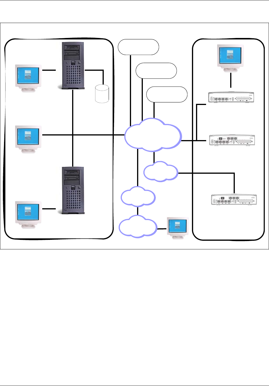
Figure 1 BCM50 network management model
“BCM50 enterprise network model” on page 28 shows an example BCM50 enterprise network,
illustrating the various communications between the BCM50 end devices and management
applications managing end devices. The diagram also shows that the physical enterprise network,
conceptually, is segmented into domains.
The Network Operations Center (NOC) domain represents the tools, equipment and activities used
to analyze and maintain the operation of a network of BCM50 devices. Element Manager and
Network Configuration Manager are the management applications which allow the network
administrators working in the NOC domain to perform the administrative functions. The
management application workstations can be physically distributed across different enterprise sites
if they are networked via an IP network as represented by the cloud in the middle of the figure.
The BCM network domain represents one or more BCM50s located a different sites in the network
connected through an enterprise LAN to one or more management application workstations. The
WAN represents an adjacent network, external to the LAN.
The VoIP and Wireless VoIP domains represent terminating IP devices.
System & Config
Management Layer
• Multi-site configuration
• Asset inventory mgmt
•Bulk MACs
Network Management Layer
• Event & Alarm Mgmt
• Infrastructure access
• Performance & optimization
• Communications
• QoS Monitoring
Element Management Tools
• Add features with keycodes
• Configuration & administration
Manageable Systems & Endpoints
• User access
• Threshold settings
• Keycodes
• User applications & capabilities
• Event / alarm generation
• System data / traffic
• Troubleshoot events & alarms
• Backup & restore
28 Chapter 2 Overview of BCM50 Administration
NN40020-600NN40020-600
Figure 2 BCM50 enterprise network model
BCM50 interfaces
The BCM50 network can be distributed geographically across different sites. The network
administrator must be able to remotely access each BCM50 in the network. BCM50 offers
alternatives for connecting to the BCM50 devices depending on the network configuration and
telephony resources available with a given system.
LAN
A Local Area Network (LAN) is a communications network that connects workstations and
computers within a confined geographical area. Often the customer LAN has access to a router,
forming a connection to the Internet.
Remote
Dialup
PSTN
NCM
Database
NCM
Server
Network
Configuration
Manager (NCM)
Element Manager
Workstation
SNMP Network
Manager
Workstation
SNMP Network
Manager Server
V.90
Modem
WAN
Wireless VoIP
VoIP
Network
Solutions
BCM Network Domain
NOC Domain

Chapter 2 Overview of BCM50 Administration 29
BCM50 Administration Guide
A network administrator can connect to and manage a BCM50 via an IP over LAN interface. If the
administrator is accessing the BCM50 system from an external network, then a connectivity path
would need to be provided from the corporate LAN network to the customer's WAN network or to
the customer's ISP provider over another device such as a router elsewhere on the customer's
premises.
Dialup
The modem supports callback for management user access to the BCM50. It can be used to
support auto-dialout on SNMP traps, as well as automated sending of Call Detail Records (CDR)
to a remote CDR collection point.
Due to modest dialup speeds, the administrator will find that the Element Manager panels take
longer to load than if the Element Manager is directly connected through the OAM port or over a
high bandwidth connection.
Configuration backups can be less than 1 Mbyte in size, however if voicemail greetings and
messages are included they could grow considerably larger. If the performance being realized over
the modem does not meet expectations, the administrator may choose to run backups to the local
hard drive or a USB memory device.
For more information on modem configuration see the BCM50 Networking Configuration Guide
(NN40020-603).
WAN
A Wide Area Network (WAN) is a communications network that covers a wide geographic area,
such as state or country. A WAN usually consists of two or more local-area networks (LANs).
Computers connected to a wide-area network are often connected through public networks, such as
the telephone system, or can be connected through private leased lines.
Management access over dial or BRI ports
You can remotely manage the BCM50 using ISDN BRI. Dial-over-ISDN is supported for any type
of BRI/PRI Media Bay Module (MBM) in an expansion chassis, and is also supported on the main
unit for the BCM50b-series models. On the BCM50b-series only, RJ-45 ports provide connectivity
for BRI trunks from the PSTN.
Protocols
Several protocols are used in the day to day management of a network of BCM50s. These include:
• SNMP (simple network management protocol): Simple Network Management Protocol is the
Internet standard protocol for network management software. It monitors devices on the
network, and gathers device performance data for management information (data)bases
(“MIB”).
• HTTPS: A secure version of HTTP implemented using the secure sockets layer, SSL,
transmitting your communications in an encrypted form. HTTPS is used between the Element
Manager and the BCM.

30 Chapter 2 Overview of BCM50 Administration
NN40020-600NN40020-600
• FTP (file transfer protocol): FTP is a protocol used to transfer files over a TCP/IP network
(Internet, Unix). FTP allows you to log into FTP servers, list directories, and copy files from
other workstations.
• SSH and other protocols are also used for certain tasks. These are covered in the section
“Secure Network Protocols and Encryption” in “Secure network protocols and encryption” on
page 74.

31
BCM50 Administration Guide
Chapter 3
BCM50 Management Environment
This chapter contains information on the different tools available for managing your BCM50
system. It also describes the Element Manager application in detail. It includes the following
sections:
•“BCM50 web page”
•“BCM50 Management Environment and Applications” on page 33
•“Element Manager” on page 36
•“BCM50 feature licensing” on page 65
•“BCM50 Help system” on page 66
•“BCM50 common file input/output processes” on page 68
BCM50 web page
The BCM50 web page facilitates the download of applications, documentation, and other
information necessary for running the BCM50 and its services. You connect to the BCM50 web
page by typing the IP address of your BCM50 device into your browser. A valid user name and
password are required in order to access the web page.
There are two default user accounts configured on the BCM50 at time of shipping: the nnadmin
user account and the nnguest user account. See Chapter 6, “Managing BCM50 Accounts and
Privileges,” on page 95 for information on user accounts and security.
You can choose to make the nnguest account available to general users. This account can be
configured to provide users with access to download end-user documents and applications that
they require from the BCM50 web page.
The BCM50 web page contains the following links:
• Quick Link - Provides links to frequently used applications, including Mailbox Manager,
Activity Reporter Basic, and CallPilot Manager.
• User Applications - Applications listed in Table 2 that are available to the end users of the
BCM50.
• Business Applications - Applications listed in Table 2 that are available to business users
of the BCM50.
• Administrator Applications - Applications listed in Table 2 that are available to BCM50
administrators.
• Documentation - Documentation for the BCM50 end users to explain the end-user
applications and BCM50-specific tasks.

32 Chapter 3 BCM50 Management Environment
NN40020-600NN40020-600
The applications available from the BCM50 webpage are supported on Windows XP, Windows
2000 Pro, and Windows Vista operating systems. Some applications, such as BCM Monitor, are
also supported on a Citrix operating system.
Table 2 Applications available on BCM50 web page
Application User Administrator
User Applications
Mailbox Manager Y Y
Desktop Assistant Pro Y Y
CallPilot Unified Messaging Y Y
Personal Call Manager Y Y
LAN CTE Client Y Y
IP Software Phone 2050* Y Y
Mobile Voice Client 2050 Y Y
Nortel VPN Client* N Y
Business Applications
Reporter Applications
Activity Reporter Basic N Y
Activity Reporter N Y
Contact Center Applications
Reporting for Contact Center N Y
Contact Center Reporting
Server
NY
Multimedia Contact Center N Y
IP View Softboard N Y
Administrator Applications
Administrator Management Tools
CallPilot Manager N Y
Business Element Manager N Y
Desktop Assistant Pro AE N Y
NCM for BCM N Y*
BCM Monitor N Y
CDR Clients N Y
BCM MIBs N Y
RADIUS Dictionary
SSH Client (PuTTY) N Y
BCM Logs N Y
Digital Mobility Tools
Digital Mobility Controller N Y
Digital Mobility Service Tool N Y

Chapter 3 BCM50 Management Environment 33
BCM50 Administration Guide
* Provides a description of the application and information about where to find it.
Administrator documentation is provided in English. User documentation is provided in the
following languages:
• English
•French
•Danish
•German
• Spanish
•Dutch
• Italian
• Norwegian
•Swedish
• Portuguese
BCM50 Management Environment and Applications
A number of tools are available to help manage your BCM50. This section describes the following
tools:
•“Managing BCM50 with Element Manager”
•“Managing BCM50 with Telset administration” on page 34
•“Managing BCM50 Voicemail and ContactCenter: CallPilot Manager” on page 34
•“Managing Digital Mobility” on page 34
•“Programming telephone sets: Desktop Assistant portfolio” on page 35
•“Performing initialization: Startup Profile” on page 35
•“Monitoring BCM50: BCM Monitor” on page 36
•“Managing BCM50 remotely with SNMP” on page 36
Templates
Startup Profile Template N Y
Factory Default Programming
Record
NY
Table 2 Applications available on BCM50 web page (Continued)
Application User Administrator

34 Chapter 3 BCM50 Management Environment
NN40020-600NN40020-600
Managing BCM50 with Element Manager
The primary management application for configuring and administering the BCM50 system is the
BCM Element Manager. The BCM Element Manager is a client-based management application
that runs on a Windows computer, or on a Citrix server. The BCM Element Manager allows for
connection to BCM50 devices over an IP network. It is used to configure, administer, and monitor
BCM50 devices. See “Element Manager” on page 36 for more information about the BCM
Element Manager.
You can download the BCM Element Manager application from the BCM50 web page. See
“BCM50 web page” on page 31 for a description of the BCM50 web page. The procedure
“Installing Element Manager on a Windows operating system” on page 37 provides detailed steps
for downloading and installing the BCM Element Manager on a Windows computer.
Managing BCM50 with Telset administration
While BCM Element Manager is the primary management application, BCM50 also supports the
programming of telephony and applications areas of BCM50 through set-based administration.
This allows installers, already familiar with this interface, to perform programming from the
keypad of any telephone connected to the BCM50 device. This alleviates the need for access to a
computer at the customer site. For more information about using Telset programming on the
BCM50, refer to the following documents:
• BCM50 Telset Administration Guide (NN40020-604)
• CallPilot Telephone Administration Guide (NN40090-500)
• Contact Center Telephone Administration Guide (NN40040-600)
Managing BCM50 Voicemail and ContactCenter: CallPilot Manager
The integrated voicemail and contact center applications are managed using CallPilot Manager,
which can be launched from Element Manager. This is the same application used to manage
voicemail and contact center applications for the BCM Release 3 software stream. For more
information about using CallPilot Manager, refer to the CallPilot documentation on the BCM50
web page.
CallPilot Manager can be launched only by users with sufficient security privileges. BCM50
administrators must assign privileges. See Chapter 6, “Managing BCM50 Accounts and
Privileges,” on page 95 for more information on security privileges.
Managing Digital Mobility
Digital mobility is managed using applications that you can download from the BCM50 webpage.
Two applications are available:
• Digital Mobility Controller (DMC) OAM program
• Digital Mobility Service Tool

Chapter 3 BCM50 Management Environment 35
BCM50 Administration Guide
You can use the DMC OAM program to configure, operate, and administer the wireless system
through the DMC. Use the Digital Mobility Service Tool to program repeaters and adjust handsets.
For more information about these applications, see the Digital Mobility System Installation and
Configuration Guide (N0000623).
Programming telephone sets: Desktop Assistant portfolio
Element Manager supports the programming of button functions for the digital and IP telephone
sets. Some administrators may want to use the Desktop Assistant family of products to complete
the customization of button programming and generate labels for the telephone sets. The Desktop
Assistant family of applications can be downloaded from the BCM50 web page. Documentation
for these applications is included within the application interface.
The Desktop Assistant family of products consists of:
• Desktop Assistant Pro
• Desktop Assistant Pro AE
For more information about Desktop Assistant tools, see the BCM50 Device Configuration Guide
(NN40020-300).
Performing initialization: Startup Profile
The Startup Profile is a template that can be edited using Microsoft Excel. It is used to accelerate
the initial installation programming of system-level parameters. It helps bring the BCM50 element
to a basic operational and ready-to-customize state without using either BCM Element Manager or
Telset administration.
The administrator must fill out the Startup Profile template, save it onto a USB storage device and
insert the storage device into the USB port of the BCM50 before the initial start-up. On start-up the
BCM50 reads the information, and starts up with the correct system parameters and feature
licensing already in place.
Some of the parameters included in the Startup Profile are:
• system name
• system profile such as country, telephony template and key voicemail attributes
• system IP parameters
• system level telephony attributes that automatically create default system DNs
• feature licensing
• user accounts
• modem status
For detailed information on the Startup Profile, see the BCM50 Installation and Maintenance
Guide (NN40020-302).
Note: You require a LAN CTE keycode to operate Desktop Assistant Pro and
Desktop Assistant Pro AE. See the LAN CTE Configuration Guide
(NN40020-602) for more information about installing and using LAN CTE.

36 Chapter 3 BCM50 Management Environment
NN40020-600NN40020-600
Monitoring BCM50: BCM Monitor
BCM Monitor is a monitoring and diagnostics tool that can monitor BCM systems. It is installed
as part of the BCM Element Manager installation. See Chapter 13, “BCM50 Utilities,” on page
191 for information about the BCM Monitor for BCM50.
Managing BCM50 remotely with SNMP
Simple Network Management Protocol is a standard for network management. BCM50 supports a
number of standard MIBs, including:
• MIB II RFC 1213
• Entity MIB RFC 2737
• Host MIB RFC 2790
• IF-MIB (RFC2863)
• SNMP-Framework-MIB (RFC2261)
SNMPv1, v2c and v3 are supported, as well as SNMP traps.
See Chapter 8, “Managing BCM50 with SNMP,” on page 137 for more information about using
Element Manager with SNMP.
Element Manager
The BCM Element Manager is a client-based management application that runs on a Windows
computer or on a Citrix server. The Element Manager allows for connection to BCM50 devices
over an IP network. It is used to configure, administer, and monitor BCM50 devices.
The BCM Element Manager allows you to connect to the BCM50 devices to be managed either
through an IP network connection, or through the craftsperson OAM port on BCM50 devices that
include a craftsperson port.
This section includes the following information on how to install and use BCM Element Manager:
•“Element Manager setup” on page 37
•“Element Manager window attributes” on page 42
•“Element Manager panels” on page 51
•“Effective use of Element Manager” on page 52
•“Element Manager data features” on page 53
•“Element Manager application logging” on page 63
•“BCM50 integrated launch of related applications” on page 64

Chapter 3 BCM50 Management Environment 37
BCM50 Administration Guide
Element Manager setup
You must perform a series of tasks before you can begin using BCM Element Manager. This
section contains the following procedures for preparing BCM Element Manager for use:
•“Installing Element Manager on a Windows operating system”
•“Installing Element Manager in a Citrix environment”
•“Accessing BCM50 using Element Manager” on page 39
•“Adding a BCM50 to the Network Element tree” on page 40
•“Finding Network Elements” on page 41
•“Disconnecting from an element” on page 42
•“Closing the Element Manager” on page 42
Installing Element Manager on a Windows operating system
You can download the BCM Element Manager application from the BCM50 web page and install
it on your computer at any time. However, you cannot connect to a BCM50 with BCM Element
Manager until the BCM50 main unit is installed and running.
The BCM Element Manager has the following system requirements:
• Windows: Windows 2000 Pro, Windows XP, or Windows Vista (Business, Ultimate, and
Enterprise versions)
• RAM: minimum 256 MB, recommended 512 MB
• free space: 150 MB
To install Element Manager on your computer:
1Connect to the BCM50 web page:
— If the BCM50 is installed on the network use a browser and type in the BCM50 IP address
as the URL in the following format:
http://xxx.xxx.xxx.xxx
— If the BCM50 is installed but not yet configured, connect directly to the BCM50 through
the OAM port and, using a browser, type the following:
http://10.10.11.1/
2Enter the user name and password to be authenticated on the BCM50 web page. See Chapter
6, “Managing BCM50 Accounts and Privileges,” on page 95 for information on default user
and passwords.
3Select the Administrator Applications link.
4Select the Business Element Manager link from the Administrator Applications web page.
5Select the Download Element Manager link from Element Manager download page.
6Select the Open button on the File Download dialog box to download and install the BCM50
Element Manager on your computer.
7Follow the prompts to install the Element Manager and BCM Monitor on your computer.

38 Chapter 3 BCM50 Management Environment
NN40020-600NN40020-600
If an older version of Element Manager is already installed on your computer, you can choose
to update the existing installation, or perform a new installation. If you choose to perform a
new installation, you can copy the existing resources to the new installation, including the
device tree, cartridges, and user preferences.
BCM Monitor replaces any older versions of BCM Monitor already installed on your
computer.
8Once the BCM50 Element Manager is installed, find the BCMEM.exe icon where you
installed it. Nortel recommends that you use the default location. The default installation
location is
C:\Program Files\Nortel\BCM50\BCMElementManager\bin\. Double-click on the
BCMEM.exe icon to launch the Element Manager.
9When the initial Element Manager window appears, take some time to orient yourself with the
various parts of the basic display. Refer to “Element Manager window attributes” on page 42.
10 Next steps:
• If the BCM50 you want to connect to is installed and has been booted up (both LEDs should
be solid green), connect your computer to either the craftsperson OAM port on the BCM50, or
to the IP network that connects to the BCM50.
• Set up the BCM50 as a device in the Network Elements tree. See “Adding a BCM50 to the
Network Element tree” on page 40 for information.
Installing Element Manager in a Citrix environment
You can run Element Manager in a Citrix environment, using the following software:
• Windows 2000 Server SP4 (fully patched)
• Citrix Metaframe XP Feature Release 3
• Citrix Program Neighborhood Version 7.0
When you run Element Manager in a Citrix environment, the Element Manager is installed on a
Citrix server. Users then run Citrix Program Neighborhood to connect to the server and launch the
Element Manager.
Element Manager is designed for single-user environments. A single installation of Element
Manager will extend the same user preferences to any Citrix user, including the device list and any
saved passwords. Citrix administrators can ensure a secure environment by using one of the
following approaches:
• install a copy of Element Manager for each user or group of users in different folders, with
Windows permissions set for the folder to control access
• in cases where a shared device tree is permitted, ensure that users do not save passwords, but
instead enter a password each time they connect
To install Element Manager on a Citrix server:
1From the Citrix server, connect to the BCM50 web page:
— If the BCM50 is installed on the network use a browser and type in the BCM50 IP address
as the URL in the following format:

Chapter 3 BCM50 Management Environment 39
BCM50 Administration Guide
http://xxx.xxx.xxx.xxx
— If the BCM50 is installed but not yet configured, connect directly to the BCM50 through
the OAM port and, using a browser, type the following:
http://10.10.11.1/
2Enter the user name and password to be authenticated on the BCM50 web page. See Chapter
6, “Managing BCM50 Accounts and Privileges,” on page 95 for information on default user
and passwords.
3Select the Administrator Applications link.
4Select the BCM50 Element Manager link from the Administrator Applications web page.
5Select the Download Element Manager link from Element Manager download page.
6Select the Open button on the File Download dialog box to download and install the BCM50
Element Manager on your computer.
7Put the Citrix server in install mode by selecting Add/Remove Programs > Add New
Program > CD or Floppy, or by entering the change user/install command from the
DOS prompt.
8Follow the prompts to install the Element Manager and BCM Monitor on your computer.
If an older version of Element Manager is already installed on your computer, you can choose
to update the existing installation, or perform a new installation. If you choose to perform a
new installation, you can copy the existing resources to the new installation, including the
device tree, cartridges, and user preferences.
BCM Monitor replaces any older versions of BCM Monitor already installed on your
computer.
9Put the Citrix server in execute mode by closing the After Installation window, or by entering
the change user/execute command from the DOS prompt.
10 Publish the Element Manager application to make it available to the users using
standard Citrix application publishing.
Accessing BCM50 using Element Manager
The first time BCM Element Manager opens it displays two panels. The Element Navigation Panel
located on the left, enables you to create a definition within Element Manager for each BCM50 to
be managing using BCM Element Manager. You can then use the icons for the elements defined
within the Element tree to perform various functions associated with that element, such as
connecting to the element or viewing log files associated with that element.

40 Chapter 3 BCM50 Management Environment
NN40020-600NN40020-600
Creating folders for network elements
Before you add a BCM50 to the network element tree, you can create folders and subfolders to
organize the devices in your network.
1While disconnected from the BCM50 device, click the New Folder icon on the task bar. You
can also right-click on Network Elements in the Network Element Navigation panel, and
select New Folder.
2Right-click on the new folder and select Rename.
3Enter a name for the folder.
Adding a BCM50 to the Network Element tree
Before you can connect to a BCM50, you must define it in Element Manager as a Network
Element.
1Select Network Elements from the Network Element Navigation panel, or, if you have
defined subfolders, select the subfolder where you want to save the device.
You can define subfolders by right-clicking on Network Elements and selecting New Folder.
If you want to move devices between folders they must be deleted from the old folder and
recreated in the new folder.
2Select Network from the menu bar or right-click on the folder heading.
3Select New Network Element > Business Communications Manager.
4In the Business Communications Manager Entry dialog box, enter the IP address for the
new network element.
5Enter the Read-Write Community String, if it is present.
The Read-Write Community String is only present if SNMP is enabled. SNMP is disabled
by default. The default SNMP Read-Write Community String is public. Contact your
system administrator to find out the correct SNMP community string to use. See Chapter 8,
“Managing BCM50 with SNMP,” on page 137 for more information about SNMP community
strings.
6Click OK to exit the dialog box.
An icon representing the newly defined element with its associated IP address appears on the
Network Elements tree.
Refer to Element Manager window attributes on page 42 for a detailed description of the common
Element Manager window elements.
Next steps: Proceed to Connecting to a BCM50 element on page 41.
Note: If you want to change the IP address to a name or other type of
identification, triple-click the IP address or right-click once on the IP address.
Once the field becomes editable, type in the new information.

Chapter 3 BCM50 Management Environment 41
BCM50 Administration Guide
Finding Network Elements
You can search for a group of BCM50s located on the same subnet by using Find Network
Elements. This function uses SNMP to search for all of the BCM50s in the specified IP address
range and add them to the Element Navigation tree. Only BCM50s with SNMP enabled will be
detected. This tool saves time when trying to quickly populate Element Manager with previously
deployed BCM50s for the first time.
Use the following procedure to find network elements:
1Right-click the Network Elements icon in the Element Navigation Panel.
2Select Find Network Elements > Business Communications Manager.
The Network Device Search dialog box appears.
3Enter the Start of IP Address range and press the tab key.
4Enter the End of IP Address range and press the tab key.
5Enter your user name in the User ID field and press the Tab key.
6Enter your password in the Password field.
7Click on the OK button
The Element Manager searches for the IP addresses specified in the range.
• If the search is successful, the BCM50s found within the IP address range are added to
Network Elements tree in the Element Navigation Panel.
• If the search is unsuccessful a Network Elements dialog box appears stating No network
elements found.
Connecting to a BCM50 element
Use the following steps to connect to your BCM50 once it is defined in the Element Manager:
1On the Network Elements tree, select the element to which you wish to connect by selecting
the IP address or element name as it appears in the Network Element tree.
Login fields appear in the Information panel.
2Enter your log in credentials for the BCM50 to which you are trying to connect.
3Perform one of the following tasks to connect to the BCM50:
• Click the Connect icon on the Icon toolbar
• Right-click on the IP address or element name and select Connect
The Element Manager attempts to connect to the selected element.
— If the connection is successful, Element Manager opens the Configuration and
Administration tabs associated to the selected device. See “Element Manager panels”
on page 51 for an explanation of the Element Manager screen layout.
— If the Element Manager fails to connect, an error message appears, describing the
connection problem. Correct the problem and perform the steps again. If you have a
recurring problem, contact Nortel Support for help in resolving the problem.

42 Chapter 3 BCM50 Management Environment
NN40020-600NN40020-600
Disconnecting from an element
You can disconnect Element Manager from a BCM50 by using one of the following:
•Disconnecting in the Element Navigation Panel on page 42
•Disconnecting through the menu bar on page 42
Disconnecting in the Element Navigation Panel
1Right-click the IP address that you want to disconnect, in the Network Element Navigation
Panel.
2Select Disconnect.
3Click Ye s in the Confirmation dialog box to confirm the disconnect request.
Disconnecting through the menu bar
1Click Session on the menu bar.
2Select the IP address of the device you want to disconnect.
3Select Disconnect from the list of tasks that are displayed.
4Click Ye s in the Confirmation dialog box to confirm the disconnect request.
Closing the Element Manager
To close the Element Manager select File > Exit, or click on the X box on the upper right corner of
the window. Close all active sessions before you close the Element Manager application.
Element Manager window attributes
The initial Element Manager window has several attributes that appear regardless of whether the
Element Manager is actively connected to a network element. Although all of the network
elements appear, some of the menu options may not be available for the selected device,
depending on the device’s state.
The following sections describe the menus and information available on the Element Manager
panel:
•Initial panel details on page 43
•Information displayed for unconnected elements on page 46
•Information displayed for connected elements on page 47
•Configuration task navigation panel details on page 48
•Administration task navigation panel details on page 50
Warning: Clicking the X box on the upper right corner causes the Element
Manager application to close and all current sessions with BCM50 devices are
terminated. Do not click on the X box to disconnect Element Manager from its
current session.
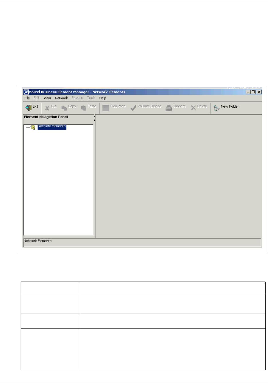
Chapter 3 BCM50 Management Environment 43
BCM50 Administration Guide
For information about navigating the panels and tables of the Element Manager, see Element
Manager data features on page 53.
Initial panel details
Figure 3 on page 43 shows the initial panel of a newly-installed Element Manager. At this point,
no network elements have been defined, and the Element Manager is not connected to any
elements.
Figure 3 Element Manager Window - no defined Elements
Table 3 lists and describes the initial Element Manager window.
Table 3 Initial Element Manager window attributes
Element Description
Title bar When you connect to a device, this area indicates the type of device (Nortel
Networks BCM50 Element Manager - Network Elements) and the IP address for
the connected device.
Menu bar The items on the menu bar are static, however, some items may be greyed out
at various stages.
File This menu provides two selections:
• Exit: a standard exit prompt that closes the Element Manager application.
You can also click on the X box on the upper right corner of the window or
click Ctrl-X
• View Network Element Logs: opens a dialog box that allows you to search for
and to view logs that are available for the connected element.

44 Chapter 3 BCM50 Management Environment
NN40020-600NN40020-600
View This menu provides three selections:
• Preferences: Allows you to choose a different appearance for the Element
Manager window.
• Network Elements: Enabled by default. If you uncheck this setting, the
Network Elements panel closes (far left panel). This does not disconnect any
connected device.
• Refresh (F5): Allows you to refresh the data shown on the window.
Network This menu is not available when a connected device is selected.
When the Network Elements folder icon is selected in the Network Elements tree
the following options are available:
• New Folder: Allows you to create a new folder on the Network Elements tree.
Folders allow you to organize your devices.
• New Network Element: Allows you to create a new entry under the Network
Elements tree. This menu item opens up a dialog box that allows you to
enter access parameters for a new Business Communications Manager
device to which you want to connect. Once you have connected to the
device, this information is saved by Element Manager and the device
remains present in the Network Elements tree. Required information is the IP
address for the device with which you want to connect.
• Find Network Elements: Opens a search dialog box that allows you to do
search for devices within a range of IP addresses by using an SNMP query.
This function only locates BCM50s that have SNMP turned on (by default,
SNMP is turned off).
When an unconnected device is selected in the network element tree, the
following options are available under the Network selection:
• Delete: Allows you to delete the original entry in the Element Manager
network element tree and create a new instance of a network element in the
tree with a new IP address. If the IP address of the device changes, you
must delete the original entry in the Element Manager network element tree
and create a new instance of a network element in the tree with a new IP
address.
• Connect: When selected, Element Manager attempts to open a connection
to the selected element. You can also connect to a network element by
right-clicking on the selected element.
• Webpage: When selected, shows the web page for the selected device.
• Validate Device: When selected, interogates the device and check for any
changes.
Session Allows you to select actions for any of the network elements to which there is a
currently active Element Manager session. If there are no active Element
Manager sessions, then this selection will be greyed out.
• Show: If multiple devices are connected, allows you to easily select one of
the connected elements from the presented list and switch the active
Element Manager view to that element.
• Disconnect: Allows you to disconnect from the device. A warning dialog box
is presented asking if you really want to disconnect from the device. You can
also disconnect from a device by right-clicking on the device in the network
element tree and selecting "Disconnect". The Element Manager remains
open.
• Save Programming Record: Allows you to save programmed information in
either Microsoft Excel format or HTML.
Table 3 Initial Element Manager window attributes (Continued)

Chapter 3 BCM50 Management Environment 45
BCM50 Administration Guide
Tools This selection provides a point from which tools relevant to the selected element
can be launched. This prompt is only active when a connected device is selected
on the Network Elements tree.
• BCM Monitor: This is a separate application, which can be installed at the
same time as Element Manager and provides a number of panels that
display current system operational information.
Help Provides information to assist in using the Element Manager.
• PDF Documents: Provides a link to the documentation interface, on the
Business Communications Manager web page, where you can find various
PDF books describing the BCM50system and programming.
• Contents: Provides a link to the help system.
Note: A brief function description appears when you mouse over field
headings. You can also access help contents by clicking on a heading and
pressing F1. Refer to “BCM50 Help system” on page 66 for more details on
Element Manager help available.
• Application Log: Collects messages generated by the Element Manager
during normal operations.
• Customer Support: Provides a link to a Nortel Networks customer support
web site.
• About: Provides information about the Element Manager, such as the
Element Manager Release level.
Icon Toolbar Icons are available if the Network Elements folder is at the top of Network
Elements tree or if an unconnected device is selected.
• Exit: Click this icon to exit BCM.
• Cut: Select a network element and click this icon to mark that netowrk
element for cutting.
• Copy: Select a network element and click this icon to mark that netowrk
element for copying.
• Paste: With no network element selected, click this button to paste a cut or
copie network element into the list of available network elements.
• Webpage: Click this button to show the web page for the selected device.
• Validate Device: Click this button to interogate the device and check for any
changes.
• Connect: Connects the Element Manager to the selected device.
• Delete: Allows you to delete the selected device from the Network Elements
tree.
• New Folder: Adds a new folder under the Network Elements tree. This icon
only works when the Network Elements title is selected.
Table 3 Initial Element Manager window attributes (Continued)

46 Chapter 3 BCM50 Management Environment
NN40020-600NN40020-600
Information displayed for unconnected elements
When you select a device in the Network Element tree to which there is currently no active
Element Manager connection, a panel is shown with a number of fields relevant to the selected
device. Some of this information does not appear until you have successfully connected to the
element with Element Manager.
Figure 4 on page 47 shows the right-hand panel in Element Manager when an unconnected
network element is selected.
The fields on this panel are described in Table 4.
Network Elements
navigation panel
This panel contains the Network Element Navigation tree which displays devices
and groups of devices (folders).
• The following actions are available in the Network Element navigation panel:
Add items: Add Network Elements or folders by right-clicking, or use the
selections under the Network menu or the Icon tool bar.
Delete items: Select the device or folder and right-click, or use the selections
under the Network menu or the Icon toolbar.
Connect/Disconnect: Select the device and right-click, or use the selections
under the Network menu or the Icon tool bar.
• The following actions are available if you right-click on an network element
listed in the Network Element Navigation tree.
Connected items - Disconnect or view logs
Unconnected items - Connect, delete, or view logs
• You can rename a folder or a network element by triple-clicking it or by
right-clicking the network element and updating the name when the name
field opens for editing.
Information panel The information in the Information panel changes depending on what is selected
in the Network Elements tree.
• If a network element is selected that is not connected: The information panel
shows the network element connection login information. Refer to
Information displayed for unconnected elements on page 46.
• If a network element is selected to which there is an Element Manager
connection: The task panel opens and shows Configuration and
Administration tabs. Refer toInformation displayed for connected elements
on page 47 for an example of the presentation of the information by Element
Manager.
Status bar The bottom bar of the Element Manager window displays the current status of
the selected item.
Expansion Arrows Clicking on these arrows will either expand or collapse the panels within the
Element Manager window. These arrows appear on all panels that have
sub-panels that can be expanded or collapsed.
Table 3 Initial Element Manager window attributes (Continued)
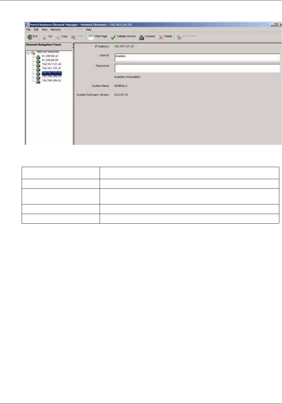
Chapter 3 BCM50 Management Environment 47
BCM50 Administration Guide
Figure 4 Information display for unconnected network element
Information displayed for connected elements
BCM Element Manager displays two panels to the right of the Network Elements navigation panel
once a BCM50 element has been connected:
• Task Navigation panel
• Information panel
Figure 5 shows the panels displayed in the Element Manager when it is connected to a BCM50.
The Task Navigation panel contains the Configuration tab and the Administration tab. See
“Configuration task navigation panel details” on page 48 for information contained in the
Configuration navigation tree. See “Administration task navigation panel details” on page 50 for
information contained in the Administration navigation tree.
Table 4 Unconnected network element information
Field Description
IP Address The IP address of the selected device.
Read-Write Community String The current community string for the selected device (shown if SNMP is
enabled).
User Name Name of an authorized BCM50 user account.
Password A valid password associated to the User Name.
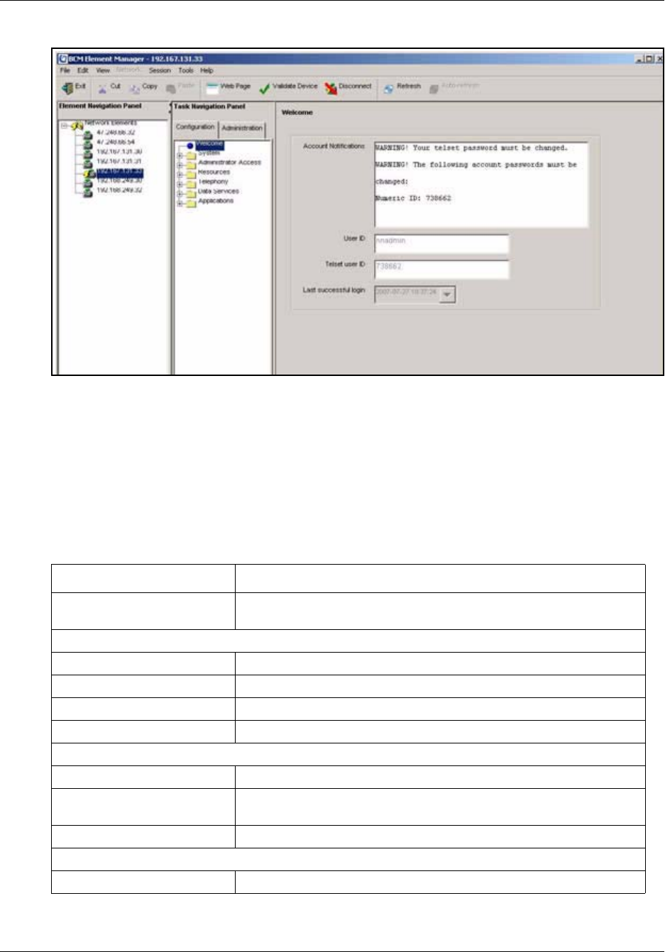
48 Chapter 3 BCM50 Management Environment
NN40020-600NN40020-600
Figure 5 Element Manager window when connected to a BCM50
Configuration task navigation panel details
The Configuration task navigation panel contains the Configuration task tree that allows you to set
up and configure your BCM50 and the attached devices.
Table 5 lists the tasks in the Configuration task tree and describes the task functions available
within the information panel when the task is selected.
Table 5 Configuration task navigation panel headings
Navigation tree heading Description
Weclome View information about the current user session, such as account
notifications, user ID, and authentication method.
System
Identification View system information.
Date and Time View and set current date and time including selection of time source.
Keycodes Retrieve, view, and manage keycodes.
IP Subsystem View information about the IP subsystem.
Administrator Access
Accounts and Privileges Manage users, groups, and privileges.
Security policies Manage passwords and other security policies, including authentication
methods.
SNMP Manage SNMP settings, and trap destinations.
Resources
Application Resources Reserved resources as well as resources in use.

Chapter 3 BCM50 Management Environment 49
BCM50 Administration Guide
Media Gateways Manage level of Echo cancellation and T.38 UDP redundancy for all
media gateways.
Port Ranges Add or delete Ports for IP Telephony.
Telephony Resources Manage location, type and status of both physical and virtual modules
including media gateways, IP trunks, and Sets.
Dial Up Interfaces View and modify settings for dial up interfaces, such as types,
protocols, and modem parameters.
Telephony
Global Settings
Feature Settings Manage feature settings and timers.
Advanced Feature
Settings
Manage SWCA, ONN Blocking, Silent Monitor and Call Log Space.
IP Terminal Features Add or delete features and view List of Key Labels.
System Speed Dial Manage speed dial numbers with bypass restrictions.
CAP Assignment View Cap number and set DN.
Sets
Active Sets Manage line access, capabilities, preferences, and restrictions of set
DNs
Active Application
DNs
Manage line access, capabilities, preferences, and restrictions of
application DNs
Inactive DNs Manage line access, capabilities, preferences, and restrictions of
inactive DNs
All DNs Manage line access, capabilities, preferences, and restrictions on all
system DNs
Lines
Active Physical Lines Manage active physical line parameters
Active VoIP Lines Manage active VoIP line parameters
Target Lines Manage target line parameters
Inactive Lines Manage inactive line parameters
All Lines Manage all lines
Loops View type, protocol, sampling, ONN blocking for BRI lines
Scheduled Services Manage scheduled service and list of possible services
Dialing Plan
General Manage settings, access codes and direct dial sets
DNs Manage DNs
Public Network Manage settings, DN lengths, and carrier codes
Private Network Manage settings, MCDN, VoIP IDs, ETSI
Line Pools View pool and access code
Routing Add or delete routes and destination codes
Ring Groups Manage group membership and line settings.
Call Security
Table 5 Configuration task navigation panel headings (Continued)

50 Chapter 3 BCM50 Management Environment
NN40020-600NN40020-600
Administration task navigation panel details
The Administration task navigation panel contains the Administration task tree that provides
access to the BCM50 that allows you to monitor and maintain your BCM50.
Table 6 lists the tasks in the Administration task tree and describes the task functions available
within the information panel when the task is selected.
Restriction Filters Add or delete restrictions and exceptions for restrictions.
Remote Access
Packages
Add or delete line pool access.
Class of Service Manage passwords for class of service as well as restrictions.
Hospitality Manage general administration, wake-up call settings, call restrictions,
and room settings.
Hunt Groups Manage group members and line assignment.
Call Detail Recording Manage report options and data file transfer settings.
Data Services
DHCP Server Manage general DHCP server settings, IP ranges, and lease info.
Router Configure router settings.
Applications
Voice Messaging/Contact
Center
Record remote voice mail system access numbers or connect to local
CallPilot applications. Launch CallPilot Manager.
Meet-Me Conferencing Configure the Meet-Me Conferencing application and set class of
service controls.
LAN CTE Manage clients, add or delete privileges.
Music Manage music settings.
Table 6 Administration task navigation panel headings
Navigation tree heading Description
General
Alarms View alarm details, clear alarm log or reset LEDs
Alarm Settings View alarm details and test alarms
SNMP Trap Destinations Add, delete or modify trap destinations
Service Manager Start, stop or restart Services (only use this feature when directed
by Nortel Networks support, as improper use can affect system
operation)
Hardware Inventory Manage general information for attached BCM50 systems and
devices
System Metrics
QoS Monitor Manage Quality of Service monitor modes, logging and mean
opinion scores
UPS Status Manage uninterrupted power supply status, events and metrics
NTP Metrics Manage network time protocol metrics synchronization details
Table 5 Configuration task navigation panel headings (Continued)

Chapter 3 BCM50 Management Environment 51
BCM50 Administration Guide
Element Manager panels
The BCM50 Element Manager Configuration and Administration trees group the various tasks and
functions required to configure the BCM50 or perform administrative tasks. When either the
Configuration tab or the Administration tab is selected, the associated task tree provides access to
the information required to complete the tasks. For example, all tasks in the Configuration tab are
configuration tasks, organized by workflow. Various types of administrative tasks are presented in
the Administration tab, such as monitoring alarms or performing backups.
Some tasks have multiple tabs within the Information panel. Information on the panels may be
grouped by related information or tasks.
Telephony Metrics
Activity Reporter Basic Enable the collection of data and set the collection time
Trunk Module Metrics Run loopback test on trunk modules
CbC Limit Metrics View (Call by Call) logs of denied calls
Hunt Group Metrics Reset metrics by hunt group
PSTN Fallback Metrics Reset PSTN fallback metrics
PVQM View voice quality metrics.
Utilities
BCM Monitor Launch BCM Monitor
Ping Send an ICMP packet to the selected switch to see if it is
reachable on the network
Trace Route Perform a trace route to specified IP address
Ethernet Activity View Ethernet activity on ports
Reset Perform a reboot of BCM50 or either a warm or cold reset of
telephony services or router
Diagnostic Settings Set release reasons for ISDN or VoIP calls
Backup and Restore
Backup Perform immediate or scheduled backups
Restore Restore Administration or Configuration settings
Logs
Log Management Perform immediate or scheduled log transfers. Types of logs are
configuration change, security, alarm, system, and component
diagnostic
Software Management
Software Updates Scheduled updates, cancel updates in progress or retrieve new
updates
Software Update History View details of software updates and remove updates
Software Inventory View software details
Table 6 Administration task navigation panel headings (Continued)

52 Chapter 3 BCM50 Management Environment
NN40020-600NN40020-600
Repetitive information such as line programming, DN programming, and system speed dial is
displayed in table format in the Element Manager. These tables allow you to change the data
display, apply filtering, sort data, or copy information between cells. If there is additional
information or configuration details available for a selected item in the table, an associated details
panel for the selected row appears below the table.
In some cases, further panels can appear beside the main table. This is the case for restriction
filters, for example, where there are three side-by-side panels that are programmed in a progressive
order from left to right.
Tabs that do not apply to a selected item appear greyed out and behind the active tabs.
You can select fields that are not read-only and enter new data either from your keyboard or by
using the drop-down box that appears when a field is selected. Data entered in these fields take
immediate effect, unless otherwise noted on the panel or in pop-up confirmation dialog boxes.
Refer to “Element Manager data features” on page 53 for details about navigating and changing
information.
Effective use of Element Manager
This section describes how Element Manager interacts with data to help the BCM50 administrator
better understand how to interact with the Element Manager.
The view users see depends on the group to which they belong. They may not be able to see all
Element Manager trees or panels. Users assigned to the nnadmin group will have administrator
privileges and can view all panels and trees available through Element Manager. See the Chapter
6, “Managing BCM50 Accounts and Privileges,” on page 95 for more information on grouping
users and assigning privileges.
The BCM50 retrieves task bullet data in real time and in sequential order. Once you select a task
bullet, Element Manager searches for the data to populate the panels and any associated detail sub-
panels or tables for the task. The first search must complete before Element Manager can start the
search for the data required for the second selected task. The first task data request is not cancelled
by the second task data request. You should only select a second task after the first task request is
completed.
Although there is some data caching done, larger tables take longer to load, as do panels with more
information in them.
Field data is committed by using add or modify buttons in panels that contain the buttons. For
panels without a Commit button use the tab or space keys to leave the field after the data has been
filled in to commit the data.
Administrators have the ability to lock out other users for a maximum of 240 minutes from
Element Manager by using the Enable Exclusive Access function in the Administrator Access >
Accounts and Privileges > Current Account tab. This ensures that there are no other users
creating changes at the same time as the administrator. See Chapter 6, “Managing BCM50
Accounts and Privileges,” on page 95 for more information on how to use Enable Exclusive
Access.

Chapter 3 BCM50 Management Environment 53
BCM50 Administration Guide
Element Manager data features
The Element Manager arranges repetitive information, such as lines programming, device record
(DN record) programming, and system speed dials into tables of information. You can manipulate
these tables in terms of data display and filtering, sorting and copying information between cells.
Other information that only requires one or two fields is arranged on composite panels that may
have more than one sub-panel. Each sub-panel includes related information.
This section provides the following descriptions:
•Adding, deleting, and modifying table information on page 53
•Copying table information on page 54
•Rearranging table information on page 56
•Using your keyboard to move around a table on page 59
Adding, deleting, and modifying table information
Some tables automatically list all available records, such as the restriction filters. These are tables
where the number of entries is restricted by the BCM50. Other tables allow you to add or delete
entries. These tables have an Add and Delete button under the table.
When you click the Add button, an add dialog box appears that allows you to enter basic
information, such as a name or DN. When you click OK, the new listing appears on the table, with
the default settings.
To modify table settings: click on the fields that you want to change and use the list to choose a
new setting, or type in the setting. If information in the table is used by more than one panel, a
Modify button may appear. Click on this button to bring up a dialog box where you can change
information, as required.
To delete table settings: click on the row you want to delete from the table, then click the Delete
button. You can select one line, or you can use the Shift or Ctrl buttons to delete a group of entries.
Figure 6 shows examples of how to select table entries for deletion.
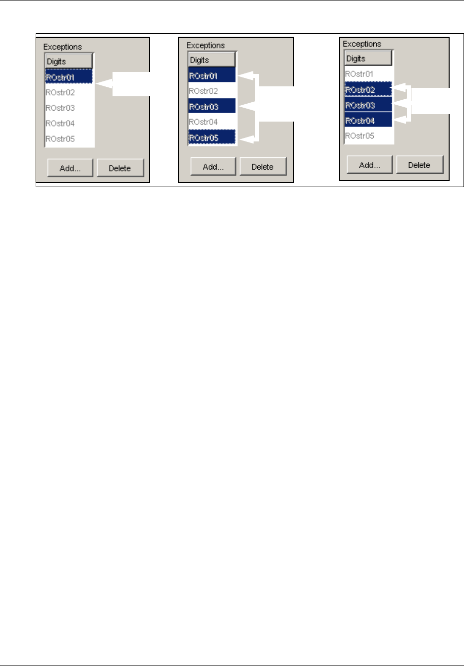
54 Chapter 3 BCM50 Management Environment
NN40020-600NN40020-600
Figure 6 Deleting table entries
Copying table information
You can copy table information using the copy and paste method on tables that require a large
amount of propagation of duplicate data. For example, tables within the Sets and Lines task tree
items contain the copy and paste functionality.
Use the following steps to copy data within a table:
1Select the row from table that you want to copy by clicking on it.
2Press the Copy button
3Select the row or rows to which you want to paste the information.
You can select multiple rows to paste data in by pressing either the Shift or Ctrl key.
4Press the Paste button
Either the Paste Set Data or the Paste Line Data dialog box appears depending on whether you
are copying data within the Sets or Lines task tree items. The check boxes within these dialog
boxes change depending on the data selected to copy. Table 7 shows the possible check boxes
that can appear and what type of data will be copied when they are selected
5Check the check boxes for the types of data that you would like to copy to the selected rows.
6Select OK to paste the information.
Select one
entry Use Control key
to select several
entries
Use Shift key
select range

Chapter 3 BCM50 Management Environment 55
BCM50 Administration Guide
The rows are updated with copied data.
Table 7 Paste Data
Check box title Settings copied Settings not copied
Control set (Lines, Sets) • Control set from the copied
source into the selected
row
Restrictions (Lines, Sets) • Set restrictions
•Set lock
• Allow Last Number Redial
• Allow Saved Number
Redial
• Allow Link
• Line/set restrictions
• Direct-dial set designation
(which set is the D-Dial set)
• CAP/TAP assignment
• ExtraDial set designation
• Service mode ringing set
designation
• Prime set designation for a
line
• Hunt group appearance
Trunk Data (Lines, Sets) • Data in common between
the copied and pasted
trunks.
• Data can be copied
between two different trunk
cartridge types
Telco data (Lines, Sets) • Call Log set (Logging set)
• 1stDisplay
• Log password
•Log space
Buttons (Sets) • All programmable set
buttons from the copied set
into the selected row’s
programmable buttons.
Line access (Sets) • Line assignment
• Line pool access
• Prime line designation
• Number of intercom keys
• Answer DNs (unless
Answer button DN is same
as telephone to which is
being copied)
• Private line appearances

56 Chapter 3 BCM50 Management Environment
NN40020-600NN40020-600
Rearranging table information
There are two ways of changing table information layout:
•Rearranging columns on page 57
•Rearranging lines on page 57
Capabilities (Sets) • Call Forward No Answer
(DN + delay + setting)
• Call Forward Busy (DN
+setting)
• DND on busy
• Handsfree setting
• Handsfree answerback
• Pickup group
• Paging zone
• Paging
• Direct-dial (which set is
reached by the D-Dial digit)
• Priority calling
• Hotline
• Auxiliary ringer
• Allow redirect
• Redirect ring
• ATA settings (except Use
ringback setting)
•Set name
• Use ringback setting under
ATA settings
• SM Supervisor
User Preferences (Sets) • Language choice
• Ring type
• Calls log options (Auto
logging)
• Display contrast
• Dialing options (automatic,
pre-dial, standard)
• External autodial button
assignments
• Internal autodial button
assignments
• Programmable button
assignments
• Ring volume
• User speed dial
• CAP/KIM module memory
button
Table 7 Paste Data (Continued)
Check box title Settings copied Settings not copied
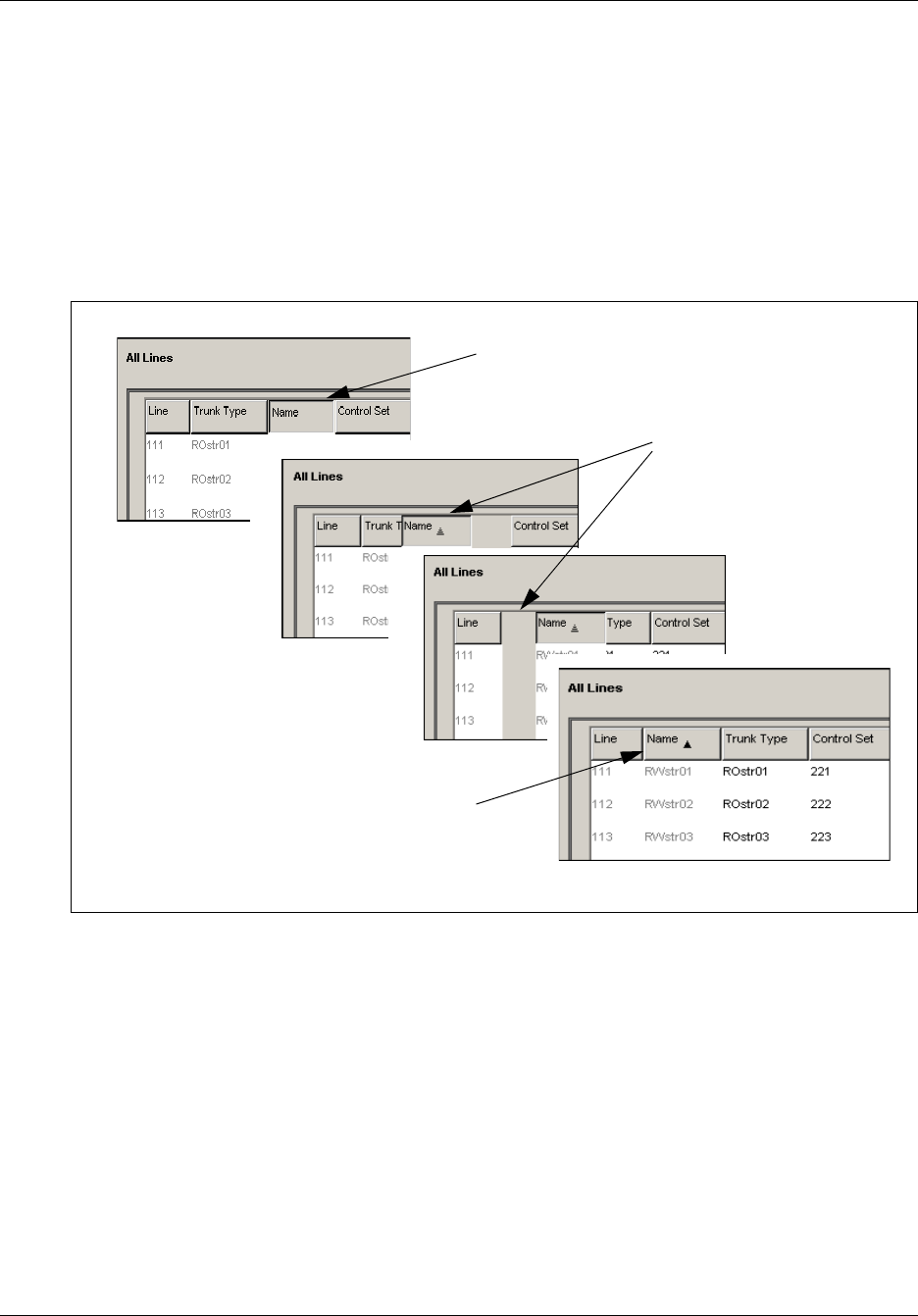
Chapter 3 BCM50 Management Environment 57
BCM50 Administration Guide
Rearranging columns
You can move columns in a table if you want to temporarily display information in a different
way. Changes to the table layouts are not saved. If you leave the panel, the columns return to the
default order.
To move a column, click and hold the column heading and drag and drop it to another location on
the table.
Figure 7 shows a step-by-step example of how to move a column within a table.
Figure 7 Changing the order of columns in a table
Rearranging lines
If you want to sort table data to make it easier to find information, use the right-click function on
table column headings to open a Sort dialog box. The Sort dialog box allows you to choose how a
table sorts lines of data.
Figure 8 on page 58 shows the Sort dialog box.
Table 8 lists and describes the fields and buttons in the Sort dialog box.
Click and hold on the
column you want to move.
Drag the column to a new position
Column is in new position.

58 Chapter 3 BCM50 Management Environment
NN40020-600NN40020-600
Figure 8 Sort dialog box
Table 8 Sort dialog box fields
Attribute Value Description
Sort By <column name>
Ascending/descending
Choose the column to uses for
sorting table data. This is the
first column the data set is
sorted by.
Then By None, <column name>
Ascending/descending
Choose the column to uses for
sorting table data. This is the
second column the data set is
sorted by.
Then By None, <column name>
Ascending/descending
Choose the column to uses for
sorting table data. This is the
third column the data set is
sorted by.
Table 9 Sort dialog box buttons
Actions Description
OK Changes are accepted and the
dialog box closes.
Apply The table rearranges, based
on the selections, but the
dialog box does not close.
Cancel No changes are made to the
sort order.
Help Help link to this page.

Chapter 3 BCM50 Management Environment 59
BCM50 Administration Guide
Using your keyboard to move around a table
Use the <Tab> key or the directional arrow keys on your keyboard to move around a table.
Saving programming records
You can create a programming file that contains the current settings of all or part of your Element
Manager data. These files can be saved in either HTML or Excel spreadsheet format. You can
access the programming record in the same way you access any other HTML file or by using
Excel, version 2002 or later, for the spreadsheet format.
A programming record that contains the factory default settings is available in Excel format from
the BCM web page.
<Tab> Each press moves the cursor to the field to the right. At the end of a
line, the next line is highlighted and the cursor continues moving to
the right.
<Shift><Tab> Each press moves the cursor to the field to the left. At the beginning
of a line, the previous line is highlighted and the cursor continues
moving to the left from the far-right field.
<Up><Down> Navigation tree: Moves cursor up/down one heading.
Non-table panels: Moves cursor up/down one heading.
Selected table: moves up/down one line.
<Left><Right> Moves cursor to the left/right of the cell. Note that this only works on
the currently-selected line.
<Shift><Enter> Moves forward through the list.
<Carriage Return> Selected field: brings up the drop-down box icon or the rotary list
icon.
Check box: selects or clears the check box.
Note: It may take several hours to save programming records, depending on the
size of the system. Nortel recommends that you saving programming records
during periods of low system use.
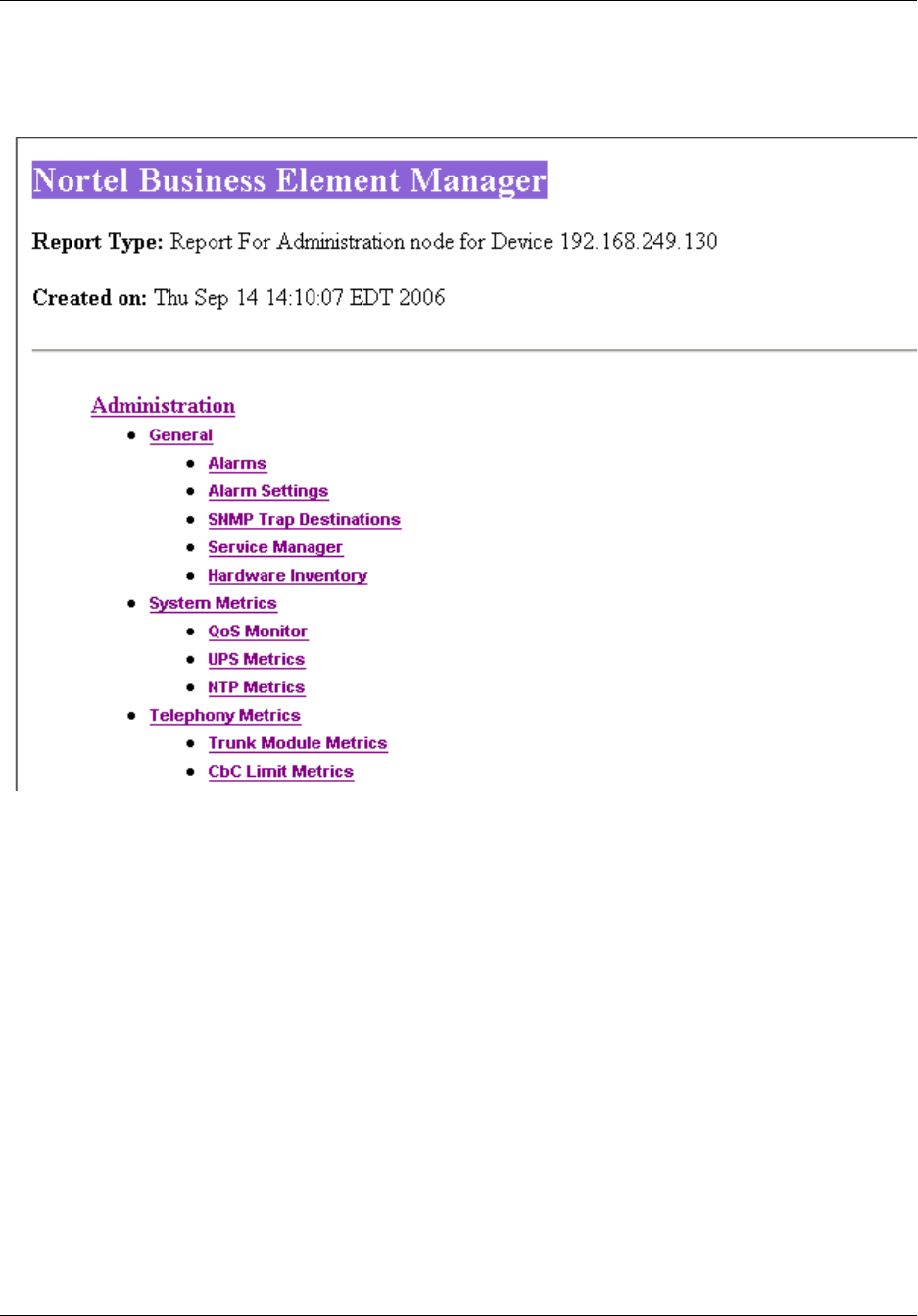
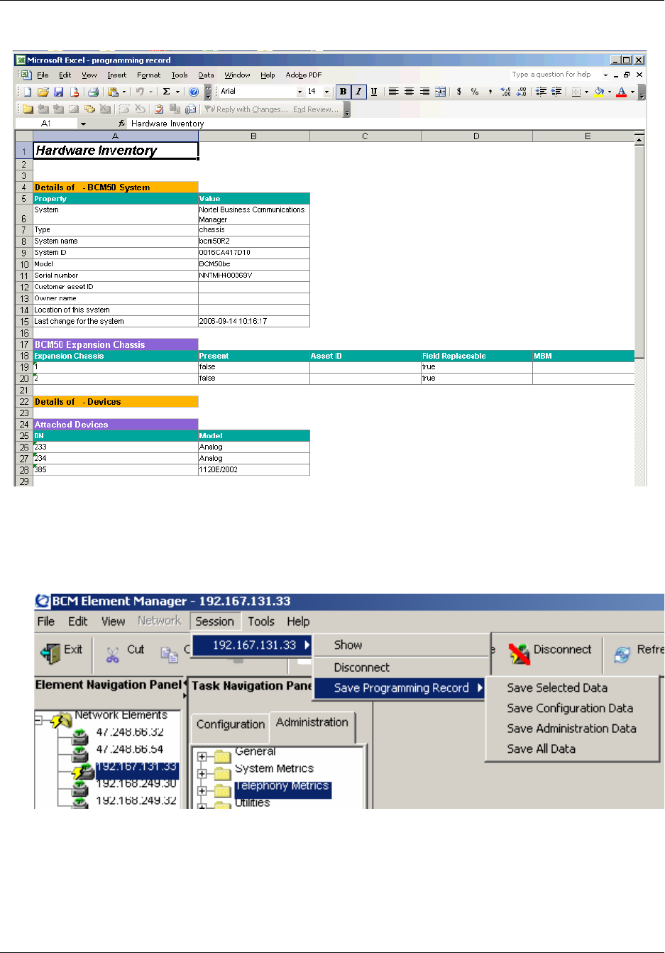
Chapter 3 BCM50 Management Environment 61
BCM50 Administration Guide
Figure 10 Programming record in an Excel spreadsheet
To create this file, you use the Save Programming Record command on the Session menu. The
Save Programming Record provides four menu options.
Figure 11 shows the menu options available.
Figure 11 Session selections for saving programming records
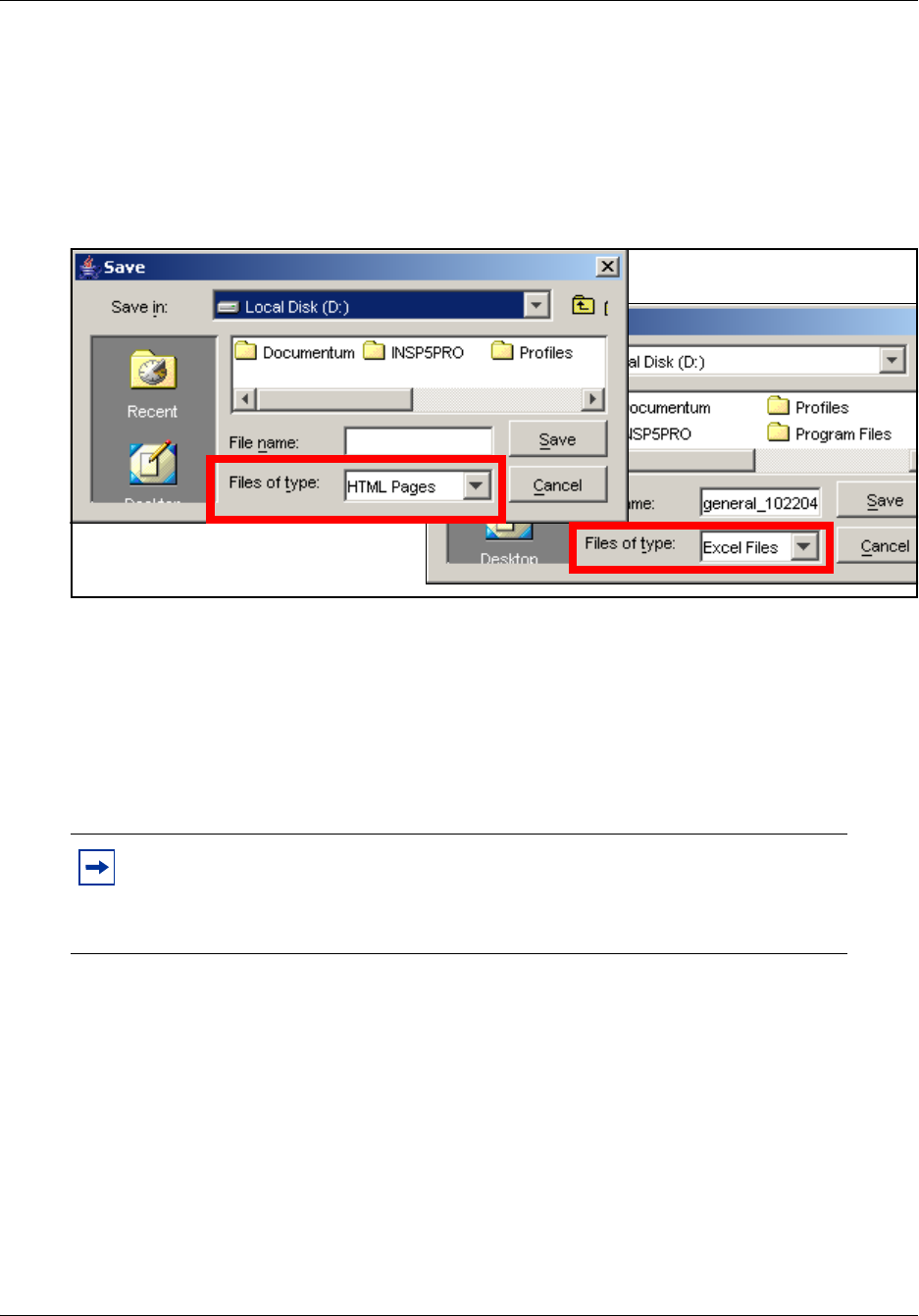
62 Chapter 3 BCM50 Management Environment
NN40020-600NN40020-600
Use the following steps to save the data programming:
1Select the item on the task navigation panel for which you want to save the data into an HTML
report or Excel workbook. An item can be a task item, task bullet, or a folder.
2Click on Session > device IP address > Save Programming Record > Save Selected Data.
A Save dialog box appears.
Figure 12 Save dialog box
3In the Save: field choose the path where you want the file stored.
4In the Files of type: field, choose the format in which you want to save the data (HTML or
Microsoft Excel spreadsheet).
5Enter a File name. Nortel recommends that you make the current date and system name part of
the file name.
6Click on Save.
Note: The Save All Data selection can take up to 45 minutes to complete. Your
computer must stay connected to the element during this time, as the Save All
Data function is actively writing into the file specified until the function is
complete.

Chapter 3 BCM50 Management Environment 63
BCM50 Administration Guide
Element Manager application logging
This section describes the logging performed by Element Manager to generate a record of its tasks.
There is usually no need to monitor Element Manager log activities. However, the log files are
available for troubleshooting should issues arise within the Element Manager operations.
When you select File > View Network Element Logs, you are prompted to open a log file in the
Log Browser. You can use the Log Browser to sort the events in the Application Log.
The BCM50 Element Manager Logs panel has three parts:
• Retrieval Criteria - This panel allows you to specify logging criteria, to clear the defined
parameters of a selected criteria, clear all retrieval criteria, retrieve logs based on the specified
criteria, or stop logging.
• Retrieval Results - This panel allows you to filter the results shown by retrieving logs based on
selected severity level check boxes.
• Log Details - shows the details of the logged message.
You can show or hide the retrieval criteria and log detail panels by clicking on the expansion arrow
beside the panel heading.
See Figure 13 on page 64 for the Application log panel.
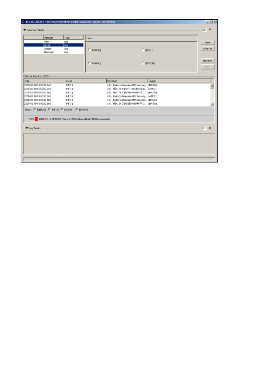
64 Chapter 3 BCM50 Management Environment
NN40020-600NN40020-600
Figure 13 Application log panel
BCM50 integrated launch of related applications
BCM50 Voicemail and CallCenter applications are managed by CallPilot Manager, and real-time
system activity is monitored with the BCM Monitor. All of these applications can be launched
through buttons provided at an appropriate location in the Element Manager. You can specify
whether you want to pass logon credentials to applications launched from the Element Manager
under View > Preferences > Tool Launch. When you pass logon credentials to these
applications, you do not need to re-enter your password when the BCM Element Manaager
launches them. These applications also have application-based Help systems.
You can launch CallPilot Manager by clicking by the Launch CallPilot Manager button under
Configuration Task > Applications > Voice Messaging/Contact Center.
The Launch CallPilot Manager button is only visible in Element Manager to groups with the
CallCenter privilege assigned to them.
Figure 14 Launch CallPilot Manager button
You can access the BCM Monitor through the Launch BCM Monitor button under
Administration Task > Utilities > BCM Monitor, or you can choose Tools > BCM Monitor.
Figure 15 on page 65 shows the location of the Launch BCM Monitor button.
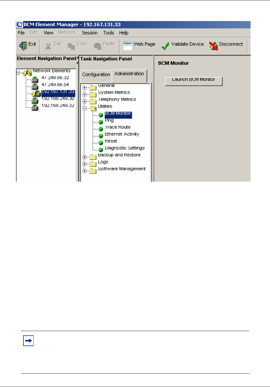
Chapter 3 BCM50 Management Environment 65
BCM50 Administration Guide
Figure 15 Launch BCM Monitor button
BCM50 feature licensing
You require a keycode to enable software features on the BCM. The keycode is a 24-digit code
that authenticates the feature or bundle of features you purchased for your BCM50.
To obtain and load a keycode you require the following:
• authorization code for the desired feature to demonstrate proof of ownership
• system ID of the system to which you want to apply the new feature
The authorization code is a six-digit code you receive for each of the features you purchase. The
authorization code can be found on the label affixed to the “Keycode information sheet” on the last
page of the Keycode Installation Guide (NN40010-301).
Figure 16 on page 66 shows the Element Manager keycode panel. See the Keycode Installation
Guide (NN40010-301) for details on BCM50 keycodes.
Note: You receive one keycode whether you purchase one feature or a bundle of
features. You receive an authorization code for each feature you purchase. For
example, if you have one feature, you receive one authorization code and one
keycode. If you purchase four features, you receive four authorization codes and
one keycode.
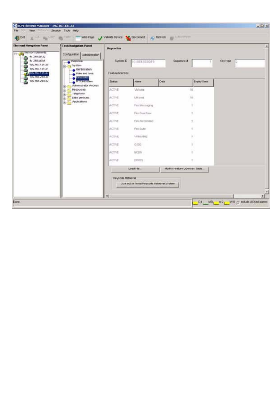
66 Chapter 3 BCM50 Management Environment
NN40020-600NN40020-600
Figure 16 BCM50 Keycode panel
BCM50 Help system
The following types of help information are available to you in Element Manager to help you
understand how to program your BCM50:
•“Menu bar Help” on page 66
•“Field-level Help” on page 67
•“Context-sensitive Help” on page 68
Menu bar Help
The menu bar help provides access to the entire Help system, which includes online help and user
manuals in PDF. Table 10 shows the help elements available from menu bar Help.
Figure 17 on page 67 shows the pull-down menu from the Help on the menu bar.
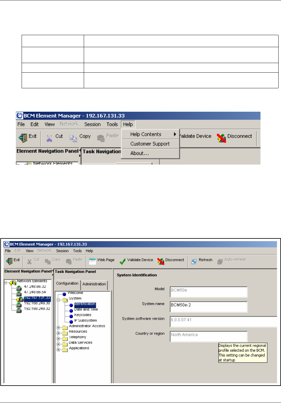
Chapter 3 BCM50 Management Environment 67
BCM50 Administration Guide
Figure 17 BCM50 Element Manager menu bar help
Field-level Help
When you position the cursor over a field, a pop-up box provides a brief description of the
information required in the field.
Figure 18 shows an example of a field-level help pop-up box.
Figure 18 Field-level Help
Table 10 Element Manager help elements
Help menu option Description
Contents Opens a browser window that shows the help information by contents or index
and allows a search.
Customer Support Opens a browser to a Nortel Networks customer support web site
About Provides information about the Element Manager software, such as the build
number.
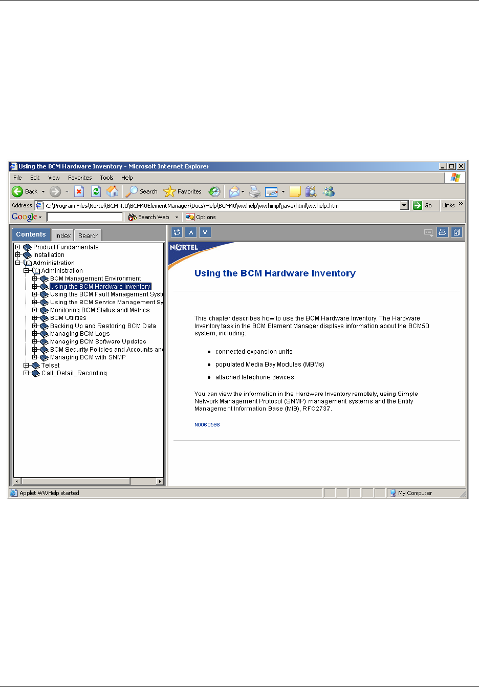
68 Chapter 3 BCM50 Management Environment
NN40020-600NN40020-600
Context-sensitive Help
You can view context-sensitive Help by clicking on a navigation tree heading, tab heading, or field
heading of a connected BCM50 device and pressing the F1 function key. This help opens an
HTML page containing overview information or panel descriptions specific to the selected
heading. Once the HTML help module opens, it also provide links to tasks and other features
related to the panel function.
Figure 19 on page 68 shows the HTML page opened when context-sensitive help is selected.
Figure 19 Context-sensitive HTML page
BCM50 common file input/output processes
Many BCM50 tasks require task data to be transferred, to or retrieved from, different destinations
or sources. BCM50 can use the following data repositories when transferring or retrieving task
data:
• BCM50
• personal computer
• network folder
•FTP server

Chapter 3 BCM50 Management Environment 69
BCM50 Administration Guide
•SFTP server
• USB storage device
• HTTP/HTTPS server
Table 11 shows the data repositories that can be used for transferring task data to or from your
BCM50 device during a task that requires data input or output.
* Available only for On Demand request of a task; not available for tasks to be run at a later time.
Comparison of data repositories
Each data repository has its advantages and disadvantages. Use this table to determine which data
repository solution matches your priorities. For example, if security is a primary concern for you,
consider setting up an SFTP or HTTPS server. If you are looking for a data repository solution that
is easy to implement, the BCM50, a personal computer, and a USB drive are all relatively easy to
set up.
The following sections contain information to help you choose the best data repository solution for
your environment and provide tips for implementation.
Table 11 Task data source and destination repositories
Task Data
Repository
Backup and
Restore Logs
Software
Updates Keycodes
BCM50 Y N N N
Personal computer Y* Y* Y Y
Network folder Y Y Y Y
FTP Y Y Y N
SFTP Y Y N N
USB storage device Y Y Y N
HTTP/HTTPS
Server
NNYN
Table 12 Comparison of data repository solutions
Task Data
Repository Ease of Use Speed Security
BCM50HHM
Personal computer H L/M/H M
Network folder M L/M/H M
USBHHL
FTPMML
SFTPLLH
HTTP/HTTPS L M L/H

70 Chapter 3 BCM50 Management Environment
NN40020-600NN40020-600
The BCM50
Storing information on the BCM50 is quick and easy, but does not protect your data in the event of
damage to the BCM50. It makes an ideal solution in small environments where the BCM50 is the
only computer on site, and where no network resources are available.
Personal computer
Storing information on a personal computer is a safe option either for short-term storage, or for
environments where only one computer is used to access Element Manager. The speed of
transferring information to or from a personal computer is based on the speed of the network.
Similarly, the security of the transfer is based on the security of the network. While this is a good
solution for on-demand transfers, it is not an option for scheduled tasks.
Network folder
A network folder is the only solution that covers backups, logs, software updates, and keycodes.
You must make sure that the folder is set up as a shared Windows resource and the BCM50 is
properly configured to have write access to the network folder. For information on setting up a
network folder, contact your network administrator. Saving information to a network folder can
take a significant amount of time. The speed and security of the transfer are based on the speed and
security of the network. See Table 13 for the information required to use a network folder.
FTP servers
Storing information on an FTP server is similar to storing information in a network folder. It offers
a centrally accessible way to store BCM50 data. The speed of transferring to an FTP server is
based on the speed of your network. Transfers to an FTP server generally have a low level of
security, unless the transfer is set up to run through a VPN.
See Table 14 for the information required to use an FTP server.
Table 13 Configure Network Folder attributes
Attribute Action
Network Folder Enter the hostname or IP address of the network folder.
User Name Enter the user name associated with the network folder.
Password Enter the password associated with the network folder.
Directory Enter the path to the subdirectory, as applicable.
Table 14 Configure FTP server attributes
Attribute Action
FTP or server Enter the hostname or IP address of the FTP server.
User Name Enter the user name associated with the FTP server.
Password Enter the password associated with the FTP server.
Directory Enter the path to the subdirectory, as applicable.

Chapter 3 BCM50 Management Environment 71
BCM50 Administration Guide
SFTP servers
The process of using an SFTP server is similar to the process for using an FTP server. However, an
SFTP server has a greater level of security than an FTP server, and more credentials are required to
use an SFTP server. You must set up and manage security keys and certificates, including
generating a SSH key, which you must then install on the SFTP server. For information on using
SFTP servers and generating SSH keys, see Chapter 5, “BCM50 Security Policies,” on page 79.
See Table 15 for the information required to use an SFTP folder.
USB storage device
Storing information to a USB storage device is a very quick way of saving information, as the
transfers occur much more quickly than network or FTP transfers, depending on the speed of the
USB drive. The USB storage device must be connected to the BCM50. The backup and log
information can be saved only to the top level of the USB storage drive file hierarchy. Transfers
from the BCM50 to a USB storage device are relatively secure, but a USB storage device is small
and can be stolen easily if it is not in a secure location. The USB storage device must be formatted
as a FAT32 drive. The following USB storage devices have been tested and are supported:
• SanDisk 512 MB Cruzer Mini USB 2.0 Flash Drive
• SanDisk 256 MB Cruzer Mini USB 2.0 Flash Drive
• Lexar 512 MB Jumpdrive Sport 2.0/Rubber C
• Kingston 256 MB 2.0 DataTraveler Memory (DataTraveler PLUS)
• Kingston DataTraveler USB FlashDrive 256 (DataTraveler ELITE)
• Apacer 256 MB USB 2.0 HT202 Handy Drive
If your USB storage device is not on this list and you are encountering problems transferring
information to or from the BCM50 device, Nortel recommends using one of the devices listed
here.
Table 15 Configure FTP or SFTP Server attributes
Attribute Action
FTP or SFTP Server Enter the hostname or IP address of the SFTP server.
User Name Enter the user name associated with the SFTP server.
Password Enter the password associated with the SFTP server.
Directory Enter the path to the subdirectory, as applicable.

72 Chapter 3 BCM50 Management Environment
NN40020-600NN40020-600
HTTP/HTTPS server
HTTP and HTTPS servers are available as an option only for software updates. It can be a good
solution if you have many BCM50s that require software updates from a centralized location. See
Table 16 for the information required to use an HTTP or HTTPS server.
Table 16 Configure HTTP or HTTPS server attributes
Attribute Action
HTTP Server Enter the hostname or IP address of the HTTP server.
User Name Enter the user name associated with the HTTP server.
Password Enter the password associated with the HTTP server.
Directory Enter the path to the subdirectory, as applicable.
Use HTTPS Specify whether the server requires SSL

73
BCM50 Administration Guide
Chapter 4
BCM50 Security Fundamentals
This chapter provides an overview of the BCM50 security policies, and outlines considerations
that network administrators should take into account when setting security policies.
Once you are familiar with the security fundamentals of the BCM50 system, you can establish
system-wide security policies and maintain access security on your system using settings on the
Element Manager. Chapter 5, “BCM50 Security Policies,” on page 79 provides procedures for
setting system-level security that applies to all configured users, for installing the web server
certificate, and for downloading the SSH key-pair. You can then configure accounts and
privileges. Chapter 6, “Managing BCM50 Accounts and Privileges,” on page 95 provides
procedures for managing access to both the Element Manager and to the telset configuration
menus.
This chapter provides an overview of the following topics:
• system security considerations
• secure network protocols and encryption
• security audits
• firewalls
• security certificate
• site authentication
System security considerations
To define security parameters for the system and for users, you must consider what level of
security you need to meet your network security standard. Note that the default security settings
are not set to their maximum secure settings and can be changed to suit your specific requirements.
Considerations
Consider the following:
• Do you want administrative users to be able to access the system through the telset
configuration menus?
!
Security Note: Nortel recommends changing all default system passwords after the
system is up and running and operation is verified.

74 Chapter 4 BCM50 Security Fundamentals
NN40020-600NN40020-600
• How much access to the Element Manager interface are users allowed?
Access is based on user privileges defined through user group membership. There is one
default Element Manager administrator account, nnadmin. This account has a default telset
user ID and password. There is also a read-only guest default account (nnguest), which does
not have a default telset user ID and password. You can delete the guest account to increase
security if you wish.
• Do you need to have a temporary account that expires?
• How long do you want the Element Manager to remain open if there is no input from the user?
• How long do you want a user account to be locked out after a specified number of incorrect
passwords are entered?
• How complex do you want user IDs and passwords to be in terms of length and character
requirements?
• Do you want modem access to use callbacks?
• Do you require the added security of a private SSL certificate?
Secure network protocols and encryption
The BCM50 uses the following network protocols for Operation, Administration and Maintenance
(OAM) in a secured mode:
• CIM/XML is the main management protocol used by the BCM50 and is only available
through an authenticated and authorized SSL connection. User access is controlled, based on
assigned privilege levels.
!
Core system configuration, such as resources and network management should be
restricted to an administrator-level account.
Use the group profiles to define other levels of users with access to the headings that
are specific to their task.
This also helps to prevent overlap programming if more than one person is using the
interface at the same time.
Dial-in access: Restrict this user group to users who require this interface. If modem
access is not required, the modem interface can be disabled to provide further security.
Note: There is also a Nortel support default user which cannot be
deleted or modified. This account is set up to allow Nortel
troubleshooting technicians to access areas of the system that are not
available to other users. You can change the default challenge key, but be
sure to retain a record of the change so that support technicians can
access your system. For more information, talk to your Nortel service
representative.

Chapter 4 BCM50 Security Fundamentals 75
BCM50 Administration Guide
• Multiple data transfer protocols are supported for the various applications including, SCP,
SAMBA, and FTP.
• SSH is used by customer support personnel for troubleshooting purposes only. There are
special authentication parameters for this interface.
Security audits
A security log file is created at system startup to record user logins and transactions. This log is
rolled each day and kept until the maximum log size is reached. When the maximum size is
reached, the oldest record is deleted to make room for the newest record. For information about
managing logs, see Chapter 15, “Managing BCM50 Logs,” on page 245.
Administrators can view security logs using the Log Management capabilities found under the
Administration tab.
Each security log record contains:
• the time of the event
• the user ID
• a summary of the action performed in the configchange.systemlog
Firewalls
Secured communications over a WAN require firewall protection. Depending on the hardware
being used and the type of security being employed, specific firewall rules must be set to enable
communication between the BCM50e/a models and the Element Manager.
If the firewall is enabled, add the following rule:
• Source address: Element Manager IP address or “Any.” This is the IP address of the system
that the Element Manager resides on.
• Destination address: BCM LAN IP address.
• Service type: TCP:5989, 443 and 80 (port number for CIM/XML, https, and http)
• Action: forward
You must configure these services for NAT: OpenWbem, HTTPs, HTTP, and CIM/XML.
Configure them using the following rules:
Table 2
Rule Services
Name OpenWbem HTTP HTTPS CIM/XML
Start Port 5989 80 443 5989

76 Chapter 4 BCM50 Security Fundamentals
NN40020-600NN40020-600
Security certificate
The BCM50 is delivered with a generic SSL security certificate. The self-signed certificate that is
included in BCM50 enables SSL encryption functionality, providing the necessary encryption
keys.
There is also a facility to generate SSH certificates which are required in the setup of a SSH server
if SCP is used as a transfer method.
Understanding BCM50 SSL certificate properties
When you first log on to the Element Manager, a security alert appears, which indicates site
validation of the default certificate.
This security alert does not appear if you:
• add a site-specific certificate
• suppress the message on your client browser
If you want a site-specific certificate, obtain a site certificate for your system from a CA
(Certificate Authority) vendor. Certificate files must use the .PEM format. When you are provided
with a certificate and a private security key, these must be installed on the BCM50.
Site authentication
Site authentication is not provided with the generic SSL certificate. This means that the generic
SSL certificate is not signed by a recognized signing authority.
However, the SSL certificate used by the http server may be upgraded to a customer’s private SSL
certificate, which offers site certification along with the encryption. Site authentication requires
system-specific information such as an IP address, company name, and so on. A site-specific
certificate ensures that when users point their web browser at the SSL web interface, the user is no
longer asked to accept the certificate.
If the default BCM50 generic SSL certificate is used, the user is prompted to accept an unsigned
End Port 5989 80 443 5989
Server IP Address BCM50 LAN IP
address
BCM50 LAN IP
address
BCM50 LAN IP
address
BCM50 LAN IP
address
!
Security note: Ensure that you maintain a copy of your certificate and private security
keys in a secure place, preferably offsite. This provides you with a backup if your system
ever requires data re-entry.
Table 2
Rule Services

Chapter 4 BCM50 Security Fundamentals 77
BCM50 Administration Guide
Additional security capabilities
In addition to the policies described in this chapter, the BCM provides security capabilities such as
NAT, VPN, DoS alert, data communication, DHCP, VLAN, and PPP. This section lists the panels
in the Element Manager where you can configure additional security functions, such as username
and passwords.
Configuration panels
•SNMP
•NTP
• Modem
• PPP
• Certificates
• Telephony scheduled services
• Telephony call security
• Hospitality
• Call Detail Recording
• DHCP server
•Router
• Voice messaging
•LAN CTE
Administration panels
•Alarms
• Alarm settings
• SNMP trap destinations
• Service manager
• Backup and Restore
• Logs
• Software Management
Applications panels
• Desktop Assistant
• DA Pro
• i2050 software phone
• Personal Call Manager
• LAN CTE Client
• CDR, BCM Monitor

78 Chapter 4 BCM50 Security Fundamentals
NN40020-600NN40020-600
•NCM

79
BCM50 Administration Guide
Chapter 5
BCM50 Security Policies
The BCM50 Security Policies panel allows you to establish system-wide security policies. This
chapter describes the security policies that you can configure through the Element Manager.
The information in this chapter is organized as follows:
•Security Policies panel on page 79 describes the fields on the Security Policies panel
•Configuring system security policies on page 84 provides procedures for setting system-level
security that applies to all configured users, for installing the web server certificate, and for
downloading the SSH key-pair
Security Policies panel
The fields that make up the Security Policies panel are described in this section. When you set
security policies, they apply to the entire BCM50 system rather than to individual users.
!
Security Note: This symbol is used throughout this section to indicate areas of possible
security concern, primarily in regard to default settings that could pose a security risk if
they are not changed.
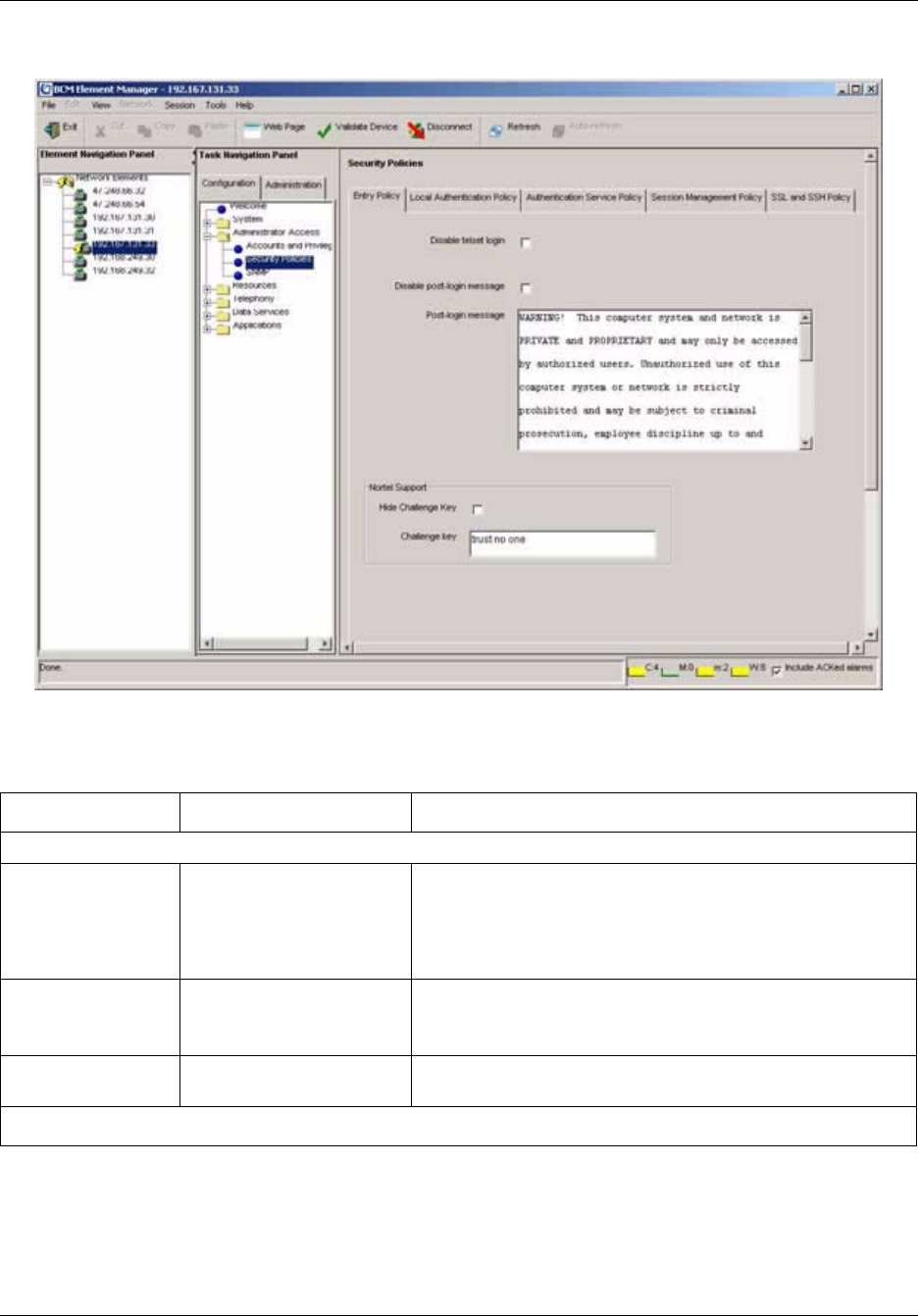
80 Chapter 5 BCM50 Security Policies
NN40020-600NN40020-600
Figure 20 Security Policies panel
The following table describes the fields on this panel:.
Table 17 Security Policies fields
Attribute Value Description
Entry Policy tab
Disable telset login check box When selected, specifies when users cannot access the system
through any telset interface. Default: unchecked
Tip: If this is enabled, and DHCP changes the system IP
address, you can determine the new IP address by way of the
OAM port.
Disable post-login
message
check box When checked, specifies that the post-login security warning
will not open on login. Default: not checked
Post login message text Displays the post-login security warning. The warning can be
edited to customize the message for your system.
Nortel Support

Chapter 5 BCM50 Security Policies 81
BCM50 Administration Guide
Challenge key Specifies an alphanumeric key. This key is part of the access
information your service technician requires to remotely access
your system. Default: trust no one.
If you change the default string, retain a record of the new string
so that Nortel Technical Support can access your system
during a support service call.
This key must be at least one character long to allow Nortel
support operation.
Show/Hide check box When checked, displays asterisks to hide the characters used
in the challenge key. Default: not checked.
Local Authentication Policy tab
Credential Complexity
Credential Type Element Manager:
Alphanumeric
Telset: Numeric
Specifies the variety of characters an alphanumeric password
must have. The required number of each type is defined by the
complexity level.
Note: User IDs are not case-sensitive.
Telset interface passwords must be numerical. Password
complexity for these passwords defines how many unique digits
are required.
Minimum User ID
length
Element Manager:
Alphanumeric 1-32
Telset: Numeric 1-16
Specifies the minimum number of characters that the system
requires for each type of credential.
Minimum password
length
Element Manager:
Alphanumeric 1-32
Telset: Numeric 1-16
Specifies the minimum number of characters that must be
entered for a new password.
Note: Alphanumeric passwords are case-sensitive.
Note: This setting must be the same as or greater than the
complexity level setting.
Example: If you have a complexity level of two, two different
types of characters or two unique numbers, the password must
be at least two characters long.
Password
Complexity Level
(Element Manager)
0
1
2
3
4
Defines the number of character types required for an
alphanumeric password. Default: 3
0: No complexity checks
1: only one character type is required
2: at least two character types are required
3: at least three character types are required.
4: all four character types are required
Note: A password complexity higher than 0 will ensure that the
user name is not used as the password. Check minimum length
setting to ensure that it is equal to or greater than the
complexity level.
Password complexity consists of the following types:
• upper case alphabet (English)
• lower case alphabet (English)
• westernized Arabic numbers
• non-alphanumeric characters ($, !, %, ^, period, comma)
Table 17 Security Policies fields (Continued)
Attribute Value Description

82 Chapter 5 BCM50 Security Policies
NN40020-600NN40020-600
Password
Complexity Level
(telset interface)
1
2
3
4
5
Specifies the number of unique digits that must be part of a
telset password:
0: No complexity checks
1: one unique digit
2: two unique digits
3: three unique digits
4: four unique digits
5: prevent consecutive numbering
Note: A password complexity higher than 0 will ensure that the
user name is not used as the password. Check the minimum
length setting to ensure that it is equal to or greater than the
complexity level.
Lockout on Failed Logon
Enable lockout check box When checked, specifies that enable lockout rules apply to
users.
Lockout counter digits Specifies the number of times the user can attempt to enter an
invalid password before the user is locked out. Default: 25; for
increased security, set this number to 5.
Lockout duration
(min)
minutes Specifies the amount of time after the user is locked out before
they are allowed to login again. Reset the lockout counter to
zero. Default: 30
Lockout counter
reset
minutes Specifies the number of minutes after a lockout before the
lockout counter is automatically reset to zero. Default: 30
Example: If the lockout counter reset is set at 30 minutes and a
user enters invalid passwords, but does not reach the lockout
counter threshold, then waits 30 minutes before trying again,
the lockout counter resets and begins counting from 1 again.
If the user enters invalid passwords until the lockout counter
threshold is reached, the Lockout duration determines when the
user can sign back onto the system.
Password Expiry
Enable password
expiry
check box When checked, specifies that the account will expire at a
specified time.
Days before
password expire
up to 256 Enter the number of days the a password can remain valid
before it must be changed.
Warning days before
password expire
Enter the number of days prior to password expiry that a user
will receive notification.
Password History
Enable password
history
checkbox When checked, the BCM stores a list of previously used
passwords and prevents users from re-using them.
Password history
length
numeric value Enter the number of previously used passwords to be stored
and checked for this account to prevent password re-use.
Authentication Service Policy tab
Table 17 Security Policies fields (Continued)
Attribute Value Description

Chapter 5 BCM50 Security Policies 83
BCM50 Administration Guide
Account
management
drop down menu Specifies the method used for authenticating users when they
log in. Options are Local Authentication and RADIUS. If
RADIUS is selected, you must also select the Enabled check
box.
Server priority Primary
Secondary
Specifies which RADIUS server will be used as the primary
server for authentication, and which server will be used as a
secondary server to authenticate users when the primary server
is unavailable.
Server name alphanumeric Name of the RADIUS server.
Server IP address <IP address> IP address of the RADIUS server.
Server Port numeric Port number of the RADIUS server.
Server shared secret alphanumeric Key required for the BCM to communicate with the RADIUS
server. Nortel recommends that the key be at least 64
characters in length.
Server message
timeout
numeric Length of time to wait for the server to respond to a request for
authentication before timing out. Nortel recommends a setting
of 2.
Server retries numeric Number of times to retry connecting with the primary server
before using an alternate means of authenticating the user.
Nortel recommends a setting of 2.
Enabled checkbox When selected, specifies that RADIUS authentication will be
used. You must also select this check box before the BCM will
use RADIUS authentication.
Session Management Policy tab
Session time out
(min.)
minutes Specifies the number of minutes a logged-in user account can
be inactive before the system ends the session and logs out the
account. If this field is left blank, the session is only ended when
the user logs off.
Active sessions
User ID Read-only Displays the user ID of the active session.
IP address Read-only Displays the IP address of the active session.
Login date Read-only Displays the login date of the active session.
SSL and SSH Policy tab
SSL
Install Web Server
Certificate (SSL)
Button Downloads application security certificates to the server where
SSH is running to ensure a secure copy connection for
operations like backup and restore, upgrades and patches.
SSH
Fingerprint alphanumeric Displays an indentifier for the application security certificate.
Table 17 Security Policies fields (Continued)
Attribute Value Description

84 Chapter 5 BCM50 Security Policies
NN40020-600NN40020-600
Configuring system security policies
This section provides procedures for setting system-level security that applies to all configured
users, for installing the web server certificate, and for downloading the SSH key-pair. Use the tabs
on the security policies panel to perform the following procedures.
Entry Policy tab
Use the Entry Policy tab to perform the following procedure:
•“Setting system access control policies” on page 85
Local Authentication Policy tab
Use the Local Authentication Policy tab to perform the following procedures:
•“Setting credential complexity” on page 85
•“Setting lockout policy for failed logins” on page 86
•“Setting password expiry policy” on page 87
•“Setting password history policy” on page 87
Authentication Service Policy tab
Use the Authentication Service Policy tab to perform the following procedures:
•“Setting the authentication method” on page 87
•“Configuring an authentication server” on page 88
Session Management Policy tab
Use the Session Management Policy tab to perform the following procedure:
•“Setting the idle session timeout” on page 92
Generate new SSH
key-pair
Button Opens the file system browser to allow a system-specific
security certificate and the accompanying Private key to be
selected for SSL.
Transfer Public Key Button Downloads a public security certificate or an SSH key-pair to an
SFTP server.
Table 17 Security Policies fields (Continued)
Attribute Value Description

Chapter 5 BCM50 Security Policies 85
BCM50 Administration Guide
SSL and SSH Policy tab
Use the SSL and SSH Policy tab to perform the following procedures:
•“Uploading a Web Server Certificate” on page 92
•“Transferring an SSH Key-Pair” on page 93
Setting system access control policies
Setting system access control policies allows the administrator to set system access rules.
To set system access control policies
1Select Configuration > Administrator Access > Security Policies > Entry Policy.
2Click in the Disable post-login message box to prevent the Warning message from opening
after login. Leave this box unchecked if you want the Warning delivered.
3Enter a new warning in the Post-login message box, or leave the default warning in the box.
4Click in the Disable telset login box to prevent users from having administrating the system
through any telset interface.
5Use the default Nortel Challenge Key, or enter a new one. If you enter a new Nortel
Challenge Key, make a record of the challenge key you use. Check the Show/Hide box if you
want to display asterisks rather than the characters used in the Challenge Key.
Setting credential complexity
Setting credential complexity allows the administrator to define the rules for password length and
password complexity.
To set credential complexity
1Select Configuration > Administrator Access > Security Policies > Local Authentication
Policy.
2In the Credential Complexity section, under the Credential Type column, select the
credential type.
3Under the Minimum User ID Length column, enter the required number of characters or
digits for a user’s ID.
4Under the Minimum Password Length column, enter the required number of characters or
digits for the user’s password.
5Under the Password Complexity Level column, enter a number from 1 to 5 that represents
the password complexity level requirement, or enter 0 if no complexity check is required. For
an alphanumeric password, the level is from 0 to 4. For a numeric password, the level is from 0
to 5.

86 Chapter 5 BCM50 Security Policies
NN40020-600NN40020-600
Variable Table
Setting lockout policy for failed logins
Setting Lockout on Failed Login allows the administrator to set lockout rules. Administrators can
unlock accounts that have been locked out; see “Re-enable a locked-out user” on page 125 for
more information.
To set lockout policy for failed logins
1Select Configuration, Administrator Access, Security Policies > Local Authentication
Policy.
2In the Lockout on Failed Login section, select the Enable lockout check box to enable
lockout capabilities.
3In the Lockout counter box, enter a number that represents the number of times a user can try
to login with an incorrect password.
4In the Lockout duration box, enter the number of minutes the user is locked out after the
Lockout counter threshold is reached.
5In the Lockout counter reset box, enter the number of minutes to wait to reset the Lockout
counter.
Variable Value
Complexity Level (Element
Manager)
0: no complexity checks
1: only one character type is required
2: at least two character types are required
3: at least three character types are required.
4: all four character types are required
A password complexity higher than 0 will ensure
that the user name is not used as the password.
The four character types are:
• lowercase letters
• uppercase letters
• numbers
• !^,.@#$%& and spaces
Complexity Level (Telset) 0: no complexity checks
1: one unique digit
2: two unique digits
3: three unique digits
4: four unique digits
5: prevent consecutive numbering (For example,
1935 or 8634971 are valid passwords. Passwords
such as 1234, 3456, 2468, 8642,8765, or 9753
would be invalid.)

Chapter 5 BCM50 Security Policies 87
BCM50 Administration Guide
Setting password expiry policy
Use this procedure to enable a password expiry policy.
To set password expiry policy
1Select Configuration, Administrator Access, Security Policies > Local Authentication
Policy.
2In the Days before password expire box, enter the number of days that a password can be
used before it expires.
3In the Warning days before password expire box, enter the number of days prior to password
expiry that the user will receive a notification.
4Select the Enable checkbox to enable the password expiry policy.
Setting password history policy
You can use the password history feature to prevent users from re-using the same password.
Administrators can configure the number of previous passwords to store and check.
To set password history
1Select Configuration, Administrator Access, Security Policies > Local Authentication
Policy.
2In the Password history section, select the Enable Password History box.
3In the Password history length box, enter the number of previous passwords to store and
check for an account.
Setting the authentication method
By default, users are authenticated on the local BCM50 system. In a network with mutliple
BCM50 systems, you can choose to authenticate users on a centralized server using RADIUS
(Remote Authentication Dial In User Service).
The BCM RADIUS client is compliant with the RADIUS protocol described in RFC 2865, and
supports the following authentication and authorization functions:
• ACCESS-REQUEST messages
• ACCESS-ACCEPT messages
• ACCESS-REJECT messages
Other functions, such as challenge key and accounting messages, are not supported.
If you use RADIUS for authenticating and authorizing users, and the RADIUS servers are not
in-service or are out-of-contact, the BCM will revert to using local authentication.

88 Chapter 5 BCM50 Security Policies
NN40020-600NN40020-600
When you select RADIUS as the authentication method, user IDs and passwords will be
authenticated on the RADIUS server for the following tasks:
• administration of the BCM using Element Manager
• access to the BCM website
• access to the BCM Monitor
• dial-in access to the BCM using modem or ISDN
• Contact Centre administration
• BCM Amp configuration
• CTE DA ProAE
• telset administration
• IP set registration
• voicemail and web-based administration
• Call Detail Recording functionality
To set the authentication method
1Select Configuration, Administrator Access, Security Policies > Authentication Service
Policy.
2From the Account Management drop-down menu, select Local Authentication or RADIUS.
If you select RADIUS, follow the procedure for “Configuring an authentication server” on
page 88.
Configuring an authentication server
To authenticate users on a centralized RADIUS server, you must configure the server using
Element Manager.
To configure an authentication server in Element Manager
1Select Configuration, Administrator Access, Security Policies > Authentication Service
Policy.
2Select a server to be the primary authentication server. Click in each column of the table to
enter the following attributes:
Column Value
Server name Name of the server to be used for authentication
Server IP address IP address of the server to be used for
authentication
Server Port Port number of the server to be used for
authentication

Chapter 5 BCM50 Security Policies 89
BCM50 Administration Guide
3Repeat step 2 to configure the secondary server.
Vendor specific attributes
The BCM requires Vendor Specific Attributes (VSAs) to be present in RADIUS client requests.
The BCM Webpage provides a RADIUS dictionary that defines the Nortel-specific attributes. The
attributes in the dictionary are defined for a Funk RADIUS server; however, the RADIUS client in
BCM complies with RFC 2865 and can be used on other RADIUS servers.
Note: For more information on the RADIUS server and the PassGo RADIUS server, refer to the
documentation provided by the respective manufacturers.
Note: For more information on Microsoft Inbuilt IAS (Internet Authentication Service), refer the
apprpriate Microsoft documentation.
In an ACCESS-REQUEST message, the BCM will look for the attributes listed in Table 18.
Table 18 Attributes in an ACCESS-REQUEST message
In an ACCESS-ACCEPT message, the BCM will look for the attributes listed in Table 19.
Shared Secret Key required for the BCM to communicate with
the authentication server
Server Message Timeout Length of time to wait for the server to respond to
a request for authentication before timing out
Server Retries Number of times to retry connecting with the
primary server before using an alternate means of
authenticating the user.
Enabled Check to enable the use of a RADIUS server
authentication.
Attribute Name Description
NAS Identifier The hostname of the BCM (string)
IP The IP address of the BCM
Calling Station ID The IP address/DN of the client attempting the
request

90 Chapter 5 BCM50 Security Policies
NN40020-600NN40020-600
Table 19 Attributes in an ACCESS-ACCEPT message
BCM requires the RADIUS server to provide one or more privilege levels when the user
authentication is accepted. Table 20 lists the privilege levels. These must be provided as a 32-bit
integer in big endian format (network byte order).
Attribute Name Value Description
RADIUS attribute type 26 Vendor specific attribute
Vendor type 562 Northern Telecom (Nortel)
Vendor attribute type 166 BCM privilege level of the user
being authenticated. Enter this
level as a hex integer.
Privilege level 0-48 (see
Ta b le 2 0 )
Privilege level of user, entered in
big endian (network byte order).

Chapter 5 BCM50 Security Policies 91
BCM50 Administration Guide
Table 20 Privilege levels
Privilege name Value Description
VoiceMailAdmin 0 Voice Mail Administrator
Contact Center 1 MMCC - Administrator
SBAInstaller 2 Set Based Administrator Level 4
SBASystemCoord 3 Set Based Administrator Level 3
SBASystemCoordBasic 4 Set Based Administrator Level 2
SBABasic 5 Set Based Administrator Level 1
Security 6 Security Administrator
CTEApp 7 LAN CTE DA Pro AE User
SBA - IP Set Registration 8 IP set registration privilege - from
IP telephone sets
Application - BCMMonitor 9 BCM Monitor user
CDRApp 10 CDR Application Privilege
Modem Login 11 Dial-in PPP user
GuestLogin 12 Access to BCM Web pages - user
level
AdminDownload 13 Administrative application
download
ExclusiveAccess 14 Access to the BCM when exclusive
access flag enabled.
Admin 16 Access to the BCM configuration.
DataAdmin 17 Access to the data portion of CIM/
XML interface.
RemoteAccess 18 Access to remote access fields of
BCM configuration.
Guest 19 Access to all of the BCM
configuration for read-only access.
VoiceAdmin 20 The ability to administer the
telephony portion of the BCM
configuration.
BackupOperator 21 The ability to backup a BCM.
RemoteMonitoring 22 The ability to remotely connect to
and manage the BCM configuration
(ie. SNMP configuration).
SoftwareUpgrade 23 The ability to upgrade the BCM.
AlarmViewer 24 The ability to view the alarm
screen.

92 Chapter 5 BCM50 Security Policies
NN40020-600NN40020-600
Setting the idle session timeout
You can use the idle session timeout feature to automatically log out users who have been inactive
for a specified period of time. Follow this procedure to specify the period of time before inactive
sessions are timed out.
To set the idle session timeout
1Select Configuration, Administrator Access, Security Policies > Session Management
Policy.
2In the Session timeout box, enter the number of minutes to wait after a period of inactivity
before the session times out.
Uploading a Web Server Certificate
This procedure allows you to upload a private security certificate to replace the generic web
certificate provided with BCM50. Using a custom site-specific certificate, you can have site
validation which will eliminate the security warnings.
For further information about security certificates, see “Security certificate” on page 76.
To upload a Web Server Certificate
1Select Configuration, Administrator Access, Security Policies > SSL and SSH Policy.
2In the SSL section, click the Install Web Server Certificate button.
3On the Transfer Certificate browse panel, locate and select the security certificate file.
4Click the Transfer Certificate button.
5On the Transfer Private Key browse panel, locate and select the private key file.
Operational Logs 26 The ability to download operational
logs.
Diagnostic Logs 27 Full access to download any logs.
ISDN - Dial-in 30 The ability to use ISDN for dial-in.
WAN - Dial-in 32 The ability to use WAN for dial-in
PPP access.
System - Serial Port 36 The ability to configure the BCM
through the serial port.
CLI access 37 The ability to access to CLI
Business Web Access 46 The ability to access Business Web
Set Programming Privilege 47 The ability to set programmes
Remote Modem Enablement 48 The ability to enable remote
modem.

Chapter 5 BCM50 Security Policies 93
BCM50 Administration Guide
6Click the Transfer Private Key button.
7On the Install Web Server certificate window, click OK to install the certificate.
Transferring an SSH Key-Pair
Transferring an SSH Key-Pair allows the administrator to download a public security certificate or
an SSH key-pair. The new certificate must be installed on each sftp server the BCM50
communicates with to ensure a secure connection for operations like backup and restore, and
software updates.
To transfer an SSH Key-Pair
1Select Configuration, Administrator Access, Security Policies > SSL and SSH Policy.
2In the SSH section, click the Generate New SSH Key-pair button.
The new key is put on the computer running BCM50.
3Click the Save button.
4For SSH Key-pair, click the Transfer Public Key button.
5On the Save dialog box, locate and select the public key file.
6Click Save to transfer the files.

94 Chapter 5 BCM50 Security Policies
NN40020-600NN40020-600

95
BCM50 Administration Guide
Chapter 6
Managing BCM50 Accounts and Privileges
BCM50 Accounts and Privileges allows you to establish accounts and access privileges for users
of the BCM50 systemThe information in this chapter is organized as follows:
•Managing user accounts and user groups on page 95 provides information about user accounts,
passwords, and privileges.
•Accounts and Privileges panel on page 109 describes the fields on the Accounts and Privileges
panel.
•Configuring user accounts, user groups and privileges on page 118 provides procedures for
managing access to both the Element Manager and to the telset configuration menus.
Managing user accounts and user groups
This section contains information on the following topics:
•User accounts on page 95
•Default passwords on page 97
•Default groups on page 97
•Default access privileges excluding set-based privileges on page 99
•Telset access security on page 107
•Blocking user accounts on page 108
User accounts
User accounts are defined by:
• a unique user ID that is visible only to authenticating services; Element Manager IDs are
alphanumeric, and Telset IDs are numeric
• a unique user name assigned for either or both the Element Manager and telset configuration
that has a minimum length that you define when you set up the security policies
• a unique password assigned for any user ID that is defined. Either password must satisfy the
Password Policy settings for the system that you define when you set up the security policies.
• a list of group attributes which allow the user specific access privileges in the system
!
Security Note: This symbol is used throughout this section to indicate areas of possible
security concern, primarily in regard to default settings that could pose a security risk if
they are not changed.

96 Chapter 6 Managing BCM50 Accounts and Privileges
NN40020-600NN40020-600
After you create an account, you can assign groups to that account. Groups are sets of privileges
based on user tasks or roles. For example, if you have a user who is responsible for remote
monitoring, you can create an account for that user and then assign a group to the account; the
group that you assign would contain the appropriate privileges for that role. The BCM has default
groups available, but you can refine the privileges available within a group to suit the needs of
your network. In this example, you could assign the default group called Remote Monitoring,
which would allow the user to do such things as view metrics and alarms.
You can create up to 200 accounts that require privileges in Element Manager, such as IPSec and
PPP. This number does not include accounts supported for voicemail users, and contact center
agents.
The User ID of the account profiles created through the set based interface cannot be modified
through the Element Manager.
Two default user accounts are provided:
• The nnadmin account is read only and cannot be deleted or disabled
• The nnguest account provides customers with web-only access. All access to the Apache web
server requires a valid administrator username and password
Auditing for user accounts includes:
• creation date, time, and the user ID that created the account
• modify date, time, and the user ID that modified the account
• expiry date and time, if enabled
• login history, including failed attempts and the date and time of the last successful attempt
• an audit log that tracks logged-in user transactions, including user account changes
Remote users can have a callback number assigned as well. This feature allows authentication of
remote users calling in through a modem. After authentication, the BCM50 will call the user back
at the number specified.
Nortel recommends that each user have a separate user account (User Name) with a unique
password. These are set up by a user with administrator privileges in the Element Manager. The
password only shows up as asterisks on the Element Manager panel. If the password is lost, the
administrator can reset the password for the user by re-entering the password in the user account.
Each user can access their own user information and change their password. User accounts can be
disabled, either manually or through dated expiry.
On the telset administration menu (F9*8), only the administrator (SBAInstaller) can enable or
disable the telset user IDs and modify or delete telset user passwords.

Chapter 6 Managing BCM50 Accounts and Privileges 97
BCM50 Administration Guide
Default passwords
The following table lists the available default passwords for the Element Manager interface, the
telset interface, and the voice mail interface.
*This account is not created by default. You must add a voicemail account using F9*8.
New accounts are created from the startup profile with a default password of Time4Chg!
Default groups
The BCM50 comes with a number of default read-only groups that provide a predetermined set of
access privileges. You can assign additional privileges to groups. Table 22 lists the default
privilege levels for each default group, which are described in “Default access privileges
excluding set-based privileges” on page 99 and “Telset access security” on page 107.
Table 21 Default passwords
User ID
Default
password Telset ID
Default telset
password Function
Available at
startup?
nnadmin PlsChgMe! 738662 266344 Read-only installer/system
administrator
yes
nnguest nnguest Read-only web-only access yes
738266 266344 Set-based installer level no
738727 727587 Set-based administration no
738236 23646 Set-based coordinator functions no
738227 22742 Set-based basic access no
voicemailadmin PlsChgMe! 738862 266344 Voicemail admin* no
– setup –– Router no
!
Security note: The default Administrator password has full access to the system. The
default password should be changed as soon as the initial system setup is complete and
system function is verified.
Table 22 Default user account groups
Group Name Privileges Notes
SBA Installer SBAInstaller
IP Set Registration
SBA - Installer group access privileges on page 108
IP Set Registration access privileges on page 100
SBA Coordinator+ SBASystemCoord SBA - System Coordinator+ group access privileges on page 108
SBA Coordinator SBASystemCoordBasic
Guests
SBA - System Coordinator group access privileges on page 108
Guests access privileges on page 103
SBA Basic SBABasic SBA - Basic group access privileges on page 108
Voice & Contact Center
Group
VoiceMailAdmin Only access to voicemail/contact center administration if this is
the only group assigned to a user account.
Voice Mail & Contact Center access privileges on page 99.

98 Chapter 6 Managing BCM50 Accounts and Privileges
NN40020-600NN40020-600
Contact Center Contact Center Only access to the Contact Centre application is available if this
is the only group assigned to a user account.
Contact Center access privileges on page 100
CDR Application CDRApp Only access to the call detail record functions is available if this is
the only group assigned to a user account.
CDR Appl access privileges on page 101
CTE Application CTEAppl CTE Appl access privileges on page 100
BCM Monitor
Application
BCMMonitorAppl BCMMonitor Appl access privileges on page 101
Administrator IP Set Registration
BCMMonitorApp
CDRApp
PPP
AdminDownload
Exclusive Access
Admin
DataAdmins
Remote Access
Voice Admins
Backup Operators
Software Upgrade
Alarm Viewer
SBA Installer
Security
CTE Appl
Operational Logs
Diagnostic Logs
VoiceMail and Contact
Center
Network IPSec
Modem dial out
ISDN dial in
ISDN dial out
WAN dial in
WAN dial out
PPOE dial in
PPOE dial out
IP Set Registration access privileges on page 100
BCMMonitor Appl access privileges on page 101
CDR Appl access privileges on page 101
PPP Access access privileges on page 101
Admin Download access privileges on page 101
Exclusive Access access privileges on page 102
Admin access privileges on page 102
DATA Admins group access privileges on page 102
Remote Access access privileges on page 103
Voice Admins access privileges on page 103
Backup Operators access privileges on page 104
Software Upgrade access privileges on page 104
Alarm Viewer access privileges on page 105
SBA - Installer group access privileges on page 108
Security access privileges on page 100
CTE Appl access privileges on page 100
Operational Logs access privileges on page 105
Diagnostic Logs access privileges on page 105
Voice Mail & Contact Center access privileges on page 99
Network IPSec access privileges on page 105
Modem dial out access privileges on page 105
ISDN dial in access privileges on page 105
ISDN dial out access privileges on page 106
WAN dial in access privileges on page 106
WAN dial out access privileges on page 106
PPPoE dial in access privileges on page 106
PPPoE dial out access privileges on page 106
Data Admin DATAAdmins DATA Admins group access privileges on page 102
Remote Access PPP
RemoteAccess
PPP Access access privileges on page 101
Remote Access access privileges on page 103
Guest Guests Guests access privileges on page 103
Voice Admin IP Set Registration
VoiceAdmins
Alarm Viewer
IP Set Registration access privileges on page 100
Voice Admins access privileges on page 103
Alarm Viewer access privileges on page 105
Table 22 Default user account groups (Continued)
Group Name Privileges Notes

Chapter 6 Managing BCM50 Accounts and Privileges 99
BCM50 Administration Guide
Default access privileges excluding set-based privileges
The group privileges further refine access availability to groups and users. You can assign more
than one privilege to a group and more than one group to a user account. The group with the most
privileges defines what the user can access.
For instance, the Admin group has all privileges, therefore, if this group is assigned to the user, any
other group assignments with less access are superseded.
The default privileges are arranged as profiles with access privileges. Access privileges for each
profile are listed in the sections below.
Voice Mail & Contact Center access privileges
• SBA -Voice Mail
• EM - CONFIG - Administrator Access - Current User
• EM - CONFIG - Applications - Voice Messaging
EM - CONFIG - Applications - Contact Center
• Web Documentation - User Documentation
•BCM50 Applications - Applications - CallPilot Manager
• Web - User Applications
Power Users IP Set Registration
DATAAdmins
VoiceAdmins
Alarm Viewer
VoiceMail and Contact
Center
IP Set Registration access privileges on page 100
DATA Admins group access privileges on page 102
Voice Admins access privileges on page 103
Alarm Viewer access privileges on page 105
Voice Mail & Contact Center access privileges on page 99
Backup Operators Security
BackupOperators
Security access privileges on page 100
Backup Operators access privileges on page 104
Security Security
AdminDownload
Alarm Viewer
Diagnostic Logs
Operational Logs
Security access privileges on page 100
Admin Download access privileges on page 101
Alarm Viewer access privileges on page 105
Diagnostic Logs access privileges on page 105
Operational Logs access privileges on page 105
Admin Download AdminDownload Admin Download access privileges on page 101
Guest Download GuestDownload Can access the BCM50 web page for application downloads and
user documentation.
Guest Download access privileges on page 101
Remote Monitoring Remote Monitor
Alarm Viewer
Operational Logs
Remote Monitoring access privileges on page 104
Alarm Viewer access privileges on page 105
Operational Logs access privileges on page 105
Table 22 Default user account groups (Continued)
Group Name Privileges Notes

100 Chapter 6 Managing BCM50 Accounts and Privileges
NN40020-600NN40020-600
Contact Center access privileges
• EM - CONFIG - Administrator Access - Current User
• Web Documentation - User Documentation
•BCM50 Applications - Applications - CallPilot Manager
• Web - User Applications
Security access privileges
• EM - CONFIG - Administrator Access - Current User
• EM - CONFIG - Administrator Access - Accounts and Privileges
• EM - CONFIG - Administrator Access - Security Policies
• EM - CONFIG - Administrator Access - SNMP
• EM - CONFIG - Administrator Access - Dial In
• EM - CONFIG - Administrator Access - Dial Out
• EM - CONFIG - Telephony - Call Security
• EM - ADMIN - General - Alarm
• EM - ADMIN - General - Alarm Setting
• EM - ADMIN - General - SNMP Trap Setting
• EM - ADMIN - General - Service Manager
• EM - ADMIN - Utilities - Reset
• EM - ADMIN - Software Management - Software Inventory Panel (read-only)
• Web Documentation - User Documentation
• Diagnostic Logs - Diagnostic Log Transfer - Diagnostic Only component logs
• SSL Certificate Transfer - Certificate Transfer - SSL Certificate & SSH Key upload /
download
• Web - User Applications
CTE Appl access privileges
• EM - CONFIG - Administrator Access - Current User
• Web Documentation - User Documentation
•BCM50 Applications - Applications - CTE DA Pro AE
• Web - User Applications
IP Set Registration access privileges
• SBA - IP Set Registration

Chapter 6 Managing BCM50 Accounts and Privileges 101
BCM50 Administration Guide
• EM - CONFIG - Administrator Access - Current User
• Web Documentation - User Documentation
• Web - User Applications
BCMMonitor Appl access privileges
• EM - CONFIG - Administrator Access - Current User
• EM - ADMIN - Utilities - BCM Monitor
• Web Documentation - User Documentation
•BCM50 Applications - Applications - BCM Monitor
• Web - User Applications
CDR Appl access privileges
• EM - CONFIG - Administrator Access - Current User
• Web Documentation - User Documentation
•BCM50 Applications - Applications - Call Detail Recording
• Web - User Applications
PPP Access access privileges
• EM - CONFIG - Administrator Access - Current User
• Web Documentation - User Documentation
• RAS - Applications - PPP
• Web - User Applications
Guest Download access privileges
• Web Documentation - User Documentation
• Web Application Download - Web Download - Callpilot Unified Messaging
• Web Application Download - Web Download - Desktop Assistant
• Web Application Download - Web Download - Desktop Assistant Pro
• Web Application Download - Web Download - 2050 Soft Phone
• Web Application Download - Web Download - Personal Call Manager
• Web Application Download - Web Download - Lan CTE Client
Admin Download access privileges
• Web Documentation - User Documentation

102 Chapter 6 Managing BCM50 Accounts and Privileges
NN40020-600NN40020-600
• Web Documentation - Admin Documentation
• Web Application Download - Web Download - Element Manager
• Web Application Download - Web Download - NCM for BCM50
• Web Application Download - Web Download - Callpilot Unified Messaging
• Web Application Download - Web Download - Desktop Assistant
• Web Application Download - Web Download - Desktop Assistant Pro
• Web Application Download - Web Download - 2050 Soft Phone
• Web Application Download - Web Download - Personal Call Manager
• Web Application Download - Web Download - Lan CTE Client
• Web Application Download - Web Download - BCM Monitor
• Web Application Download - Web Download - CDR Client Wrapper Utility
• Web Application Download - Web Download - SSH
Exclusive Access access privileges
• EM - CONFIG - Administrator Access - Current User
• Web Documentation - User Documentation
• Web - User Applications
Admin access privileges
• all privileges
DATA Admins group access privileges
• EM - CONFIG - System - IP Subsystem
• EM - CONFIG - Administrator Access - Current User
• EM - CONFIG - Administrator Access - Dial In
• EM - CONFIG - Administrator Access - Dial Out
• EM - CONFIG - Resources - Media Gateways
• EM - CONFIG - Data Services- DHCP Server Settings
• EM - CONFIG - Data Services- Class 1 Router
• EM - ADMIN - General - Alarm
• EM - ADMIN - General - Alarm Setting
• EM - ADMIN - Utilities - BCM Monitor
• EM - ADMIN - Utilities - Ping
• EM - ADMIN - Utilities - Trace Route

Chapter 6 Managing BCM50 Accounts and Privileges 103
BCM50 Administration Guide
• Web Documentation - User Documentation
• Web - User Applications
Remote Access access privileges
• EM - CONFIG - Administrator Access - Current User
• EM - CONFIG - Administrator Access - SNMP
• EM - CONFIG - Administrator Access - Dial In
• EM - CONFIG - Administrator Access - Dial Out
• EM - ADMIN - General - SNMP Trap Destinations
• Web Documentation - User Documentation
Guests access privileges
• Read-only access to all but Utilities, Backup and Restore, and Log Management
• EM - CONFIG - Administrator Access - Current User
• Web Documentation - User Documentation
• Web - User Applications
Voice Admins access privileges
• EM - CONFIG - System - Identification
• EM - CONFIG - System - Time and Date
• EM - CONFIG - System - Keycodes
• EM - CONFIG - System - IP Subsystem
• EM - CONFIG - Administrator Access - Current User
• EM - CONFIG - Resources - all
• EM - CONFIG - Telephony - all
• EM - CONFIG - Data Services - DHCP Server Setting
• EM - CONFIG - Applications - LAN CTE
• EM - CONFIG - Applications - Voice Messaging
• EM - CONFIG - Applications - Contact Center
• EM - ADMIN - General - Alarm
• EM - ADMIN - General - Alarm Setting
• EM - ADMIN - Utilities - Inventory
• EM - ADMIN - General - Alarm
• EM - ADMIN - General - Alarm Setting

104 Chapter 6 Managing BCM50 Accounts and Privileges
NN40020-600NN40020-600
• EM - ADMIN - System Status - Qos Monitor
• EM - ADMIN - System Status - NTP Metrics
• EM - ADMIN - Telephone Metrics - all
• EM - ADMIN - Utilities - BCM Monitor
• EM - ADMIN - Utilities - Reboot
• EM - ADMIN - Software Management - all as read only
• Web Documentation - User Documentation
Backup Operators access privileges
• EM - CONFIG - Administrator Access - Current User
• EM - ADMIN - Backup and Restore - Admin - Backup
• EM - ADMIN - Backup and Restore - Admin - Restore
• Web Documentation - User Documentation
• Web - User Applications
Remote Monitoring access privileges
• EM - CONFIG - Administrator Access - Current User
• EM - ADMIN - General - Alarm as read only
• EM - ADMIN - General - Alarm Setting as read only
• EM - ADMIN - General - SNMP Trap Destinations
• EM - ADMIN - General - Service Manager as read only
• EM - ADMIN - General - Inventory as read only
• EM - ADMIN - System Status - Qos Monitor
• EM - ADMIN - System Status - UPS Metrics as read only
• EM - ADMIN - System Status - NTP Metrics as read only
• EM - ADMIN - Telephone Metrics - all
• EM - ADMIN - Utilities - BCM Monitor
• Web Documentation - User Documentation
• Web - User Applications
Software Upgrade access privileges
• EM - CONFIG - Administrator Access - Current User
• EM - ADMIN - Utilities - Reboot
• EM - ADMIN - Software Management - all

Chapter 6 Managing BCM50 Accounts and Privileges 105
BCM50 Administration Guide
• Web Documentation - User Documentation
• Web - User Applications
Alarm Viewer access privileges
• EM - CONFIG - Administrator Access - Current User
• EM - ADMIN - General - Alarm
• EM - ADMIN - General - Alarm Setting
• EM - ADMIN - General - Inventory
• Web Documentation - User Documentation
• Web - User Applications
Operational Logs access privileges
• Web Documentation - User Documentation
• EM - ADMIN - Log Management- Operational Logs
• Web - User Applications
Diagnostic Logs access privileges
• Web Documentation - User Documentation
• EM - ADMIN - Log Management- Diagnostic Logs
Network IPSec access privileges
• EM - CONFIG - Administrator Access - Current User
• RAS - Application - IPSec
Modem dial out access privileges
• EM - CONFIG - Administrator Access - Current User
• Web Documentation - User Documentation
• Web - User Applications
• PPP dial out via analog modem
ISDN dial in access privileges
• EM - CONFIG - Administrator Access - Current User
• Web Documentation - User Documentation
• Web - User Applications

106 Chapter 6 Managing BCM50 Accounts and Privileges
NN40020-600NN40020-600
• PPP dial in via ISDN
ISDN dial out access privileges
• EM - CONFIG - Administrator Access - Current User
• Web Documentation - User Documentation
• Web - User Applications
• PPP dial out via ISDN
WAN dial in access privileges
• EM - CONFIG - Administrator Access - Current User
• Web Documentation - User Documentation
• Web - User Applications
• PPP dial in via analog WAN
WAN dial out access privileges
• EM - CONFIG - Administrator Access - Current User
• Web Documentation - User Documentation
• Web - User Applications
• PPP dial out via WAN
PPPoE dial in access privileges
• EM - CONFIG - Administrator Access - Current User
• Web Documentation - User Documentation
• Web - User Applications
• PPP dial in via PPPoE
PPPoE dial out access privileges
• EM - CONFIG - Administrator Access - Current User
• Web Documentation - User Documentation
• Web - User Applications
• PPP dial out via PPPoE

Chapter 6 Managing BCM50 Accounts and Privileges 107
BCM50 Administration Guide
Telset access security
You can use the Telset administration interface (FEATURE 9*8) to activate or deactivate the telset
default access user accounts. You can also use this interface to change the password for these
accounts. For further information about using telset features, see the Telset Admin Guide.
The Telset group privileges apply specifically to the following telset interfaces:
• FEATURE 9*8 (Administrator access only)
• FEATURE **266344 (**CONFIG) (telephony interface)
• FEATURE 983 (CallPilot interface)
These interfaces are meant to be used only as supplementary configuration portals. You can also
block access to these interfaces when you set up the system Security Policies.
Table 23 Default Telset access
Configuration Heading Parameters Comments
System ID A read-only field in Feature 9*8 used for
keycode entry.
Region Uses Feature ** PROFILE on the set. See
Norstar documentation.
IPADDRESS Dynamic
Address
Subnet
Dfltgwy
License FILE
Keycode data
Uses Keycodes that can be entered one at a
time through Feature 9*8 .
TelephonyStartup Template Uses Feature ** STARTUP on telset within 15
minutes of a bootup of BCM. See Norstar
documentation.
StartDN Uses Feature ** STARTUP on telset within 15
minutes of a bootup of BCM. See Norstar
documentation.
VOICEMAILSTARTUP ATTENDANTDN Uses Feature 983 the first time you initialize
CallPilot. See CallPilot documentation.
UISTYLE Uses Feature 983 the first time you initialize
CallPilot. See CallPilot documentation.
LANGUAGE Uses Feature 983 the first time you initialize
CallPilot. See CallPilot documentation.

108 Chapter 6 Managing BCM50 Accounts and Privileges
NN40020-600NN40020-600
Telset group access privileges
There are four set-based group access privileges. These are listed in order of greatest to least
access privileges with SBA - Installer being the group with the greatest privileges.
SBA - Installer group access privileges
• SBA - Feature 9*8
• SBA - Installer Rights
• IP Set Registration (when IP set registration is configured and a global password setting is
used)
• EM - CONFIG - Administrator Access - Accounts and Privileges - Current User
• Web Documentation - User Documentation
•BCM50 Applications - User Applications
SBA - System Coordinator+ group access privileges
• SBA - Coordinator Plus Rights
• EM - CONFIG - Administrator Access - Accounts and Privileges - Current User
• Web Documentation - User Documentation
•BCM50 Applications - User Applications
SBA - System Coordinator group access privileges
• SBA - Coordinator Rights
• EM - CONFIG - Administrator Access - Accounts and Privileges - Current User
• Web Documentation - User Documentation
•BCM50 Applications - User Applications
SBA - Basic group access privileges
• SBA - Basic Rights
• EM - CONFIG - Administrator Access - Accounts and Privileges - Current User
• Web Documentation - User Documentation
•BCM50 Applications - User Applications
Blocking user accounts
There are different ways that you can block user access to the system based on your security and
administrative requirements.

Chapter 6 Managing BCM50 Accounts and Privileges 109
BCM50 Administration Guide
• Primarily, you can block unauthorized access by ensuring that you change all default
passwords once the system is set up and verified.
• You can also block user access by simply changing the password. Note that you must retain a
record of the password, since this information is not displayed either on the Element Manager
panel or in the programming record file.
• You can increase the complexity required for both Element Manager and telset passwords to
make it more difficult for unauthorized users to inadvertently guess the correct password.
Complexity is increased by increasing the type of characters that are required and by
increasing the minimum length of the password.
• You can set up the system to lock out a user if the password is entered incorrectly a
(configurable) number of times. You can unlock the account through the user account record,
or the user can wait for the lockout timer to run out before attempting to log on again. The user
account shows the last time a user failed to logon.
• You can set a user account to automatically expire on a given date.
• You can manually disable the account. If the user is currently logged in, this takes effect at the
next log-in.
• If you only want to decrease the amount of system access, you can delete groups and reassign
groups with lower access privileges to the user account.
The administrator performing maintenance tasks can lock the system during the duration of the
maintenance. Any user already logged in remains logged in, but would not be able to log in again
until the Exclusive Access timer runs out.
Accounts and Privileges panel
This section describes the tabs and fields available on the Accounts and priveleges panel.
Current Account
The Current Account context panel provides a summary of user information about the person
currently signed into the Element Manager.
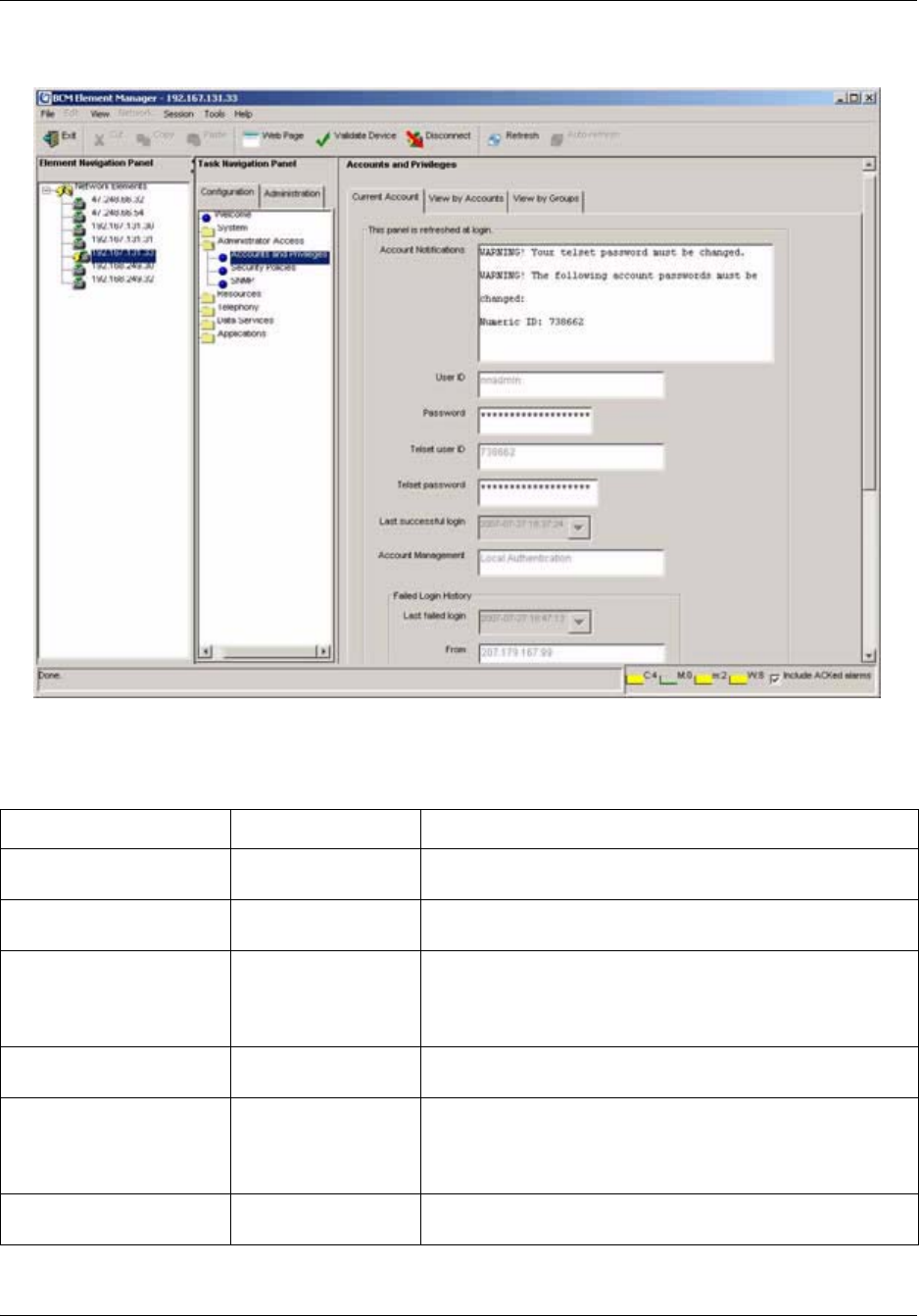
110 Chapter 6 Managing BCM50 Accounts and Privileges
NN40020-600NN40020-600
Figure 21 Accounts and Privileges: Current Account panel
Table 24 describes each field on the Current Account context panel.
Table 24 Current Account fields
Attribute Value Description
Account Notifications read-only This field displays account notifications, such as notifications
of password expiries.
User ID read-only A read-only field that can only be changed on the user
accounts panel by a user with administrator privileges
Password alphanumeric Requires a password entry that contains all the security
requirements. Refer to “Setting credential complexity” on page
85.
Note: Changes to the password take effect at the next login.
Telset user ID read-only A read-only field, and can only be changed on the user
accounts panel by a user with administrator privileges
Telset password numeric Requires a numeric password entry that is unique for each
user. These strings must satisfy the security requirements.
Refer to “Setting credential complexity” on page 85.
Note: This password takes effect at the next login.
Last Successful log-in read-only A read-only field that indicates the last date and time the user
account was used to log on to the system.

Chapter 6 Managing BCM50 Accounts and Privileges 111
BCM50 Administration Guide
Account Management read-only Displays the method used to authenticate the user session:
local authentication, or centralized authentication through a
RADIUS server.
Failed Login History
Last failed login read-only Displays the date and time of the last failed login.
From Displays the interface from which the login was attempted.
Failed Telset Login History
Last failed login read-only Displays the date and time of the last failed login by a Telset
user.
From Displays the interface from which the login was attempted.
Exclusive access time
remaining
numeric
minutes
Specifies the amount of time left before other users are
allowed to log on to the system. Visible only to users with
administrator-level privileges.
Buttons
Enable Exclusive Access This button is visible only to users with exclusive access
privileges. Opens the Enable Exclusive Access dialog box
from which you enter the amount of time that you want to have
exclusive access to the system. Exclusive Access does not
disable the access of users who are currently logged in.
Disable Exclusive Access Stops the exclusive access timer and allow other users back
onto the system. This button is visible only to users with
exclusive access privileges.
Table 24 Current Account fields (Continued)
Attribute Value Description
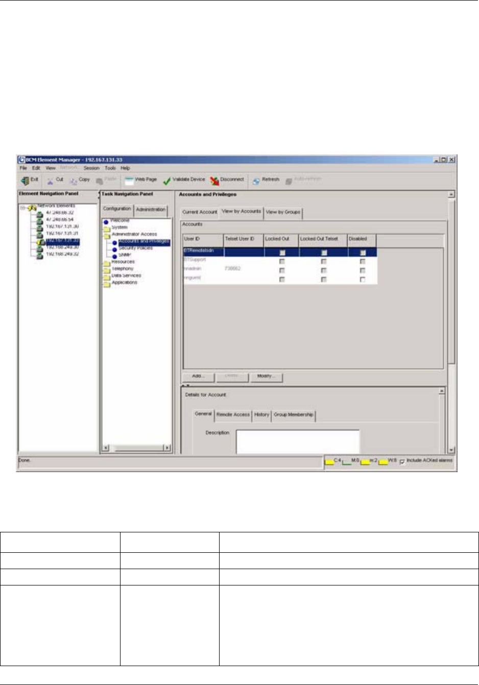
112 Chapter 6 Managing BCM50 Accounts and Privileges
NN40020-600NN40020-600
View by Accounts
The View by Accounts context panel contains the table that defines individual user accounts. On
these panels, you define how the system identifies the user. You also define what privileges the
user has by assigning the user to groups.
You can add, delete, or modify user account information from this panel. When you add or modify
a user, you can enter a password for both the Element Manager interface and the telset interface.
Figure 22 Accounts and Privileges, View by Accounts context panel
Table 25 describes each field on the View by Accounts panel.
Table 25 View by Accounts fields
Attribute Value Description
User ID alphanumeric Displays the accounts by User ID
Telset User ID numeric Displays the accounts by Telset User ID
Locked Out checkbox Indicates whether or not the user has been locked out. When
checked, the user cannot access the system. This field
becomes checked when a user enters an incorrect password
too many times, and the system locks the user account.
The user either has to wait for the lockout timer to run out, or
an administrator can unlock the user’s access using
“Re-enable a locked-out user” on page 125.

Chapter 6 Managing BCM50 Accounts and Privileges 113
BCM50 Administration Guide
If you select a user on the Users list, two more panels appear in the lower frame:
• The General panel allows you to see the current status of the account. See “View by Account:
General” on page 113
• The Group Membership panel allows you to associate the account to group profiles, which
determines what type of access the user has. See “View by Account: Group Membership” on
page 115.
View by Account: General
The General panel provides user account information and account control settings.
Table 26 describes each field on this panel.
Locked Out Telset checkbox Indicates whether or not the user has been locked out. When
checked, the user cannot access the system. This field
becomes checked when a user enters an incorrect password
too many times, and the system locks the user account.
The user either has to wait for the lockout timer to run out, or
an administrator can unlock the user’s access using
“Re-enable a locked-out user” on page 125.
Disabled checkbox Indicates whether a user account has been disabled. When
checked, the user cannot access the system. This field
becomes checked when the account expiry date is reached.
Refer to “Enabling and disabling an account” on page 126.
Buttons
Add Opens the Add Account dialog box
Delete Deletes the selected user account
Modify Opens the Modify Account dialog box
!
Security note: You cannot delete the nnadmin user; therefore, ensure that you change
the default password as soon as possible after system setup. Keep a record of the
password in a safe place.
Table 26 View by Accounts: General fields
Attribute Value Description
Description alphanumeric Displays the descriptive name and information for the user or the user
function. This field may be left blank.
Account Expriy
Enable account expiry check box When selected, specifies that the user account is scheduled to
automatically expire at the specified date and time.
Account will be
disabled on
date Specifies the date and time when the user account will expire. The
pull-down menu opens a calendar.
Table 25 View by Accounts fields
Attribute Value Description

114 Chapter 6 Managing BCM50 Accounts and Privileges
NN40020-600NN40020-600
View by Account: Remote Access
The Remote Access panel provides callback settings for verifying user information, as well as
configuration of NAT rules for dial-up users.
Table 27 describes each field on this panel.
Account Textual Credentials
Change password on
login
check box When selected, forces a user to change his or her password when
logging in.
Password expiry drop-down menu Specifies the date to force a password change.
Account Telset Credentials
Change password on
login
check box When selected, forces a Telset user to change his or her password
when logging in.
Password expiry drop-down menu Specifies the date to force a Telset password change.
Table 27 View by Accounts: Remote Access
Attribute Value Description
Modem Callback
Number
telephone # Specifies the number the system will call to verify the dial-up user
access
Modem Callback
Passcode
User ID Specifies the passcode the system uses to confirm the callback is
legitimate
ISDN Callback
Number
telephone # Specifies the number the system will call to verify the ISDN user access
ISDN Callback
Passcode
User ID Specifies the passcode the system uses to confirm the callback is
legitimate
IP Address
BCM IP Address IP address Specifies the PPP IP address of the BCM when connecting with analog
modem or ISDN terminal adaptors.
NAT Rules*
Rule 1: Dial-in Side IP address Enter an IP address on a dial-in interface to be translated.
LAN Side IP address Enter an IP address on the local LAN to use when translating the dial-in
address in Rule 1.
Rule 2: Dial-in Side IP address Enter an IP address on a dial-in interface to be translated.
LAN Side IP address Enter an IP address on the local LAN to use when translating the dial-in
address in Rule 2.
Rule 3: Dial-in Side IP address Enter an IP address on a dial-in interface to be translated.
LAN Side IP address Enter an IP address on the local LAN to use when translating the dial-in
address in Rule 3.
Rule 4: Dial-in Side IP address Enter an IP address on a dial-in interface to be translated.
Table 26 View by Accounts: General fields (Continued)
Attribute Value Description

Chapter 6 Managing BCM50 Accounts and Privileges 115
BCM50 Administration Guide
View by Account: History
The History panel provides user account and login histories and account control settings.
Table 28 describes each field on this panel.
View by Account: Group Membership
The Group Membership panel allows you to associate the user account with one or more
functional groups. The user will have all the privileges assigned to each group that is added to the
list.
LAN Side IP address Enter an IP address on the local LAN to use when translating the dial-in
address in Rule 4.
*Multicast IP addresses cannot be used for NAT rules.
Table 28 View by Accounts: History fields
Attribute Value Description
Account history
Account created
Created by
read-only Specifies the date that the user record was added.
Specifies the userID of the person who added the user account.
Last Modified
Modified by
read-only Specifies the date the user record was last modified.
Specifies the userID of the person who last modified the account.
Login history
Last successful login read-only Specifies the date the user last successfully logged on to either the
Element Manager.
Failed login count read-only Specifies the number of times the user tried and failed to log on before
successfully logging in or being locked out. If the count matches the
failed login threshold, a value of true is displayed in the Locked Out
column on the Accounts table.
Last failed login read-only Specifies the date that the user last tried and failed to logon.
From read-only Element Manager: Displays the IP address of the Element Manager
Telset login history
Last successful login read-only Specifies the date the user last successfully logged on to Telset.
Failed login count read-only Specifies the number of times the user tried and failed to log on before
successfully logging in or being locked out. If the count matches the
failed login threshold, a value of true is displayed in the Locked Out
column on the Accounts table.
Last failed login read-only Specifies the date that the user last tried and failed to logon.
From read-only Telset: Displays the DN of the telephone used to log into the system.
Table 27 View by Accounts: Remote Access (Continued)
Attribute Value Description

116 Chapter 6 Managing BCM50 Accounts and Privileges
NN40020-600NN40020-600
Table 29 describes each field on this panel.
View by Groups
The View by Groups panel allows you to add or delete members from group profiles.
The Groups panel lists all the groups currently available in the system.
Table 30 describes each field on this panel.
For more details about groups, refer to the panels described in “View by Groups: General” on page
116.
View by Groups: General
For a selected entry in the Groups table (“View by Groups” on page 116), you can use the General
details panel to define which system privileges are assigned to this group, and to users assigned
with this group.
This panel also provides status information for the group.
Table 29 Group membership fields
Attribute Value Description
Account is
Member of
Groups
Default groups Lists groups the user is a member of. Refer to “Default groups”
on page 97 for a list of the default groups and the privileges
associated with each.
Note: Groups are added, modified or deleted from the “View by
Groups” on page 116 panel.
Buttons
Add Opens the Add Account dialog box. Choose the group or
groups with the appropriate access privileges for the user.
Note: You cannot add user accounts to groups with read-only
privileges.
Delete Deletes the user account from the selected group.
Table 30 View by Groups fields
Attribute Description
Groups Lists all the defined groups. Refer to “Default groups” on page 97 for a list of the
default groups and the privileges associated with each.
Buttons
Add Opens the Add Group dialog box. Allows the creation of custom groups that provide
combinations of privileges not covered by the default groups.
Delete Opens the Confirm Delete dialog box. Allows for the deletion of any group, with the
exception of the Admin Group.

Chapter 6 Managing BCM50 Accounts and Privileges 117
BCM50 Administration Guide
Table 31 describes each field on this panel.
Table 31 View by Groups: General panel fields
Attribute Value Description
Group History
Group created
Created by
read-only Specifies the date the group account was created
Specifies the user who created the account
Last modified
Modified by
read-only Specifies the last date the group account was changed
Specifies the user who performed the changes
Privileges: Group Privileges
Privilege read-only Lists the system access privileges that are allowed to members of the
selected group
Actions:
Add Opens the Add Privilege to Group dialog box. Allows the privilege to be
added to the group
Delete Opens the Confirm Delete dialog box. Allows the privilege to be deleted
from a group

118 Chapter 6 Managing BCM50 Accounts and Privileges
NN40020-600NN40020-600
View by Groups: Members
For a selected group in the Groups table (“View by Groups” on page 116), you can use the
Members panel to assign the group to existing user accounts and to view which accounts have the
selected group assigned.
Table 32 describes each field on this panel.
Configuring user accounts, user groups and privileges
User Management provides procedures for managing access to both the Element Manager and to
the telset configuration menus. You can control when users can log on, how much they can see,
and what they can do within the configuration menus.
This section provides the following procedures:
•“Adding a new user account” on page 119
•“Modifying a user account” on page 119
•“Adding callback for a dial-up user” on page 120
•“Adding NAT rules for a dial-up user” on page 120
•“Adding Telset access for a user” on page 121
•“Deleting a user account” on page 121
•“Changing a user’s password” on page 122
•“Changing the current user’s password” on page 122
•“Creating a group” on page 123
•“Deleting a group” on page 123
•“Modifying group privileges” on page 123
•“Adding a user account to a group” on page 124
•“Deleting a user account from a group” on page 124
•“Re-enable a locked-out user” on page 125
Table 32 View by Groups: Group Membership fields
Attribute Value Description
Description read-only Lists the user accounts in the selected group.
User ID alphanumeric Displays the accounts by User ID.
Telset User ID numeric Displays the accounts by Telset User ID.
Buttons:
Add Opens the Add Account to Group dialog box. Allows the user account to
be added to the selected group.
Delete Deletes the selected user account from the selected group.

Chapter 6 Managing BCM50 Accounts and Privileges 119
BCM50 Administration Guide
•“Enabling and disabling an account” on page 126
•“Enabling and disabling exclusive access” on page 127
Adding a new user account
Administrators can create user accounts when the BCM is configured to authenticate users locally.
After you create a new user account, you can assign groups to that account. Groups are sets of
privileges based on user tasks or roles. For information about creating groups and assigning groups
to accounts, see “Creating a group” on page 123 and “Adding a user account to a group” on page
124.
To add a new user account
1Select Configuration, Administrator Access, Accounts and Privileges, View by Account
tab.
2Click the Add button.
3In the Add Account dialog box, enter a description of the account in the Description field.
4Enter the user’s identifier in the User ID field.
5In the User password field, enter the user’s password.
6In the Confirm password dialog box, enter the user’s password again.
7In the Telset password field, enter the telset password for the user.
8In the Confirm password dialog box, enter the user’s password again.
9If the user is connecting through a modem, enter the number the system dials to contact the
client modem in the Modem Callback Number field and enter a passcode in the Modem
Callback Passcode field. Ensure you include the correct routing codes.
10 If the user is connecting through ISDN, enter the number the system dials to contact the client
in the ISDN Callback Number field and enter a passcode in the ISDN Callback Passcode
field.
11 Select the Change Password on Login checkbox to force a password change when the user
logs into Element Manager.
12 Select the Change Password on Login Telset checkbox to force a password change when the
user logs into Telset.
13 Click OK to save the user account.
After the account is created, the user can change their own password through the Current Account
panel. Refer to “Changing the current user’s password” on page 122.
Modifying a user account
As an administrator, you can modify user accounts.

120 Chapter 6 Managing BCM50 Accounts and Privileges
NN40020-600NN40020-600
To modify a user account
1Select Configuration, Administrator Access, Accounts and Privileges, View by Account
tab.
2Select an existing user on the Accounts table and click the Modify button.
3On the Modify Account dialog box, make the changes you require.
4If callback for dial-up users is required, see “Adding callback for a dial-up user” on page 120.
5If telset access is required, see “Adding Telset access for a user” on page 121.
6Click OK to save the user account.
Adding callback for a dial-up user
As an administrator, you can provide callback access to a user who is accessing the system through
a dial-up connection.
To add callback for a dial-up user
1Select Configuration, Administrator Access, Accounts and Privileges, View by Account,
Remote Access tab.
2Select an existing user on the Accounts table.
3If the user is connecting through a modem, enter the number the system dials to contact the
client modem in the Modem Callback Number field and enter a passcode in the Modem
Callback Passcode field. Ensure you include the correct routing codes.
4If the user is connecting through ISDN, enter the number the system dials to contact the client
in the ISDN Callback Number field and enter a passcode in the ISDN Callback Passcode
field.
5Click OK.
Adding NAT rules for a dial-up user
As an administrator, you can add Network Address Translation (NAT) rules for a user who is
accessing the system through a dial-up connection. When you add a NAT rule, your network can
use one set of IP addresses for internal traffic and a second set of IP addresses for external traffic.
This translation provides security for your LAN by hiding the IP addresses of devices on your
network from external computers. The procedure in this section allow you to configure NAT on
dial-up interfaces.
!
Callback security
If a user is connecting to the system using a modem, you can enhance your access
security by assigning that person a specific user account that prompts the system to
acknowledge the user, then hang up and dial back the user at a designated telephone
number, before allowing the person to have access to the system.

Chapter 6 Managing BCM50 Accounts and Privileges 121
BCM50 Administration Guide
Note: When you set NAT rules for a dial-up user, the NAT rule overrides the Allow Network Access
setting. For information about the Allow Network Access setting, see “Configuring dial-in parameters” in
the BCM50 Networking Configuration Guide. You will also need to configure the dial-in PC with a subnet
route to be able to connect to the BCM50 over a PPP interface.
To add NAT rules for a dial-up user
1Select Configuration, Administrator Access, Accounts and Privileges, View by Account,
Remote Access tab.
2Select an existing user on the Accounts table.
3Click Modify.
4In the Rule 1: Dial-in Side field, enter the IP address to be translated from.
You cannot use a multicast address when you create NAT rules.
5In the LAN Side field to the right, enter the IP address on the local LAN to be translated to.
You cannot use a multicast address when you create NAT rules.
6Repeat steps 3 and 4 to create addition rules.
7Click OK.
Adding Telset access for a user
As an administrator, you can provide an existing user with access to the system through a
set-based connection.
To add Telset access for a user
1Select Configuration, Administrator Access, Accounts and Privileges, View by Account
tab.
2Select an existing user on the Accounts table and click the Modify button.
3In the Telset User I D field, enter the user’s identifier.
4In the Telset Password field, enter the user’s telset password.
5Re-enter the telset password in the Confirm Password dialog box.
6Click OK.
Deleting a user account
As an administrator, you can delete user accounts when they are not needed.

122 Chapter 6 Managing BCM50 Accounts and Privileges
NN40020-600NN40020-600
To delete a user account
1Select Configuration, Administrator Access, Accounts and Privileges, and click the View
by Account tab.
2Select a user on the Users table.
3Click the Delete button.
4In the confirmation box, click Yes to remove the user account from the system.
Changing a user’s password
As an administrator, you can change a user’s forgotten password, or reset the user password for
each user to enforce regular password-change policy. You can also force a password change when
the user logs in.
To change a user’s password
1Select Configuration, Administrator Access, Accounts and Privileges, View by Account
tab.
2Select the user record from the table and click Modify.
3In the Modify Account window, delete the asterisks in the Password or Telset password
field.
4Enter a new password and click OK.
5Re-enter the password in the Confirm Password dialog box.
6Provide the user with this password and request that they change it as soon as possible through
the Current User panel (“Current Account” on page 109) or click on Change Password on
Login to make a password change mandatory.
Changing the current user’s password
As a user or an administrator, you must change your password periodically.
To change the current user’s password
1Select Configuration, Administrator Access, Accounts and Privileges, Current Account
panel.
2Select the password field that needs to be changed.
!
\Security note: An integral part of your system security is password management. This
includes changing default passwords after the system is installed. To further increase
access security, minimize the number of user accounts, especially the administrator
accounts, and change passwords regularly.

Chapter 6 Managing BCM50 Accounts and Privileges 123
BCM50 Administration Guide
3Enter a new password that conforms with the system password policies, which are defined by
the administrator during system setup.
A confirmation dialog box appears.
4In the confirmation dialog box, enter the new password again.
5Click OK.
The password takes effect the next time you log in.
Creating a group
As an administrator, you can create new groups to satisfy organizational requirements.
To create a group
1Select Configuration, Administrator Access, Accounts and Privileges, View by Groups
tab.
2Click the Add button.
3In the Add Group dialog box, enter a name for the new group.
4Click OK.
5Select the new group from the Groups list.
6In the Group Privileges area, click the Add button.
7In the Add Privilege to Group dialog box, select one or more group privileges to assign to the
group and click OK. See “Default groups” on page 97 and “Default access privileges
excluding set-based privileges” on page 99 for more information.
8Populate the group using “Adding a user account to a group” on page 124.
Deleting a group
As an administrator, you can delete groups as organizational requirements change.
To delete a group
1Select Configuration, Administrator Access, Accounts and Privileges, View by Groups
tab.
2Select a group and click the Delete button.
3Click Yes on the confirmation box to remove the groups from the list.
Modifying group privileges
Only user-created groups can be modified; default group privileges cannot be modified.

124 Chapter 6 Managing BCM50 Accounts and Privileges
NN40020-600NN40020-600
To modify group privileges
1Select Configuration, Administrator Access, Accounts and Privileges, View by Groups
tab.
2Select a group and then click the General tab.
3To remove privileges, click on the Group Privileges tab, select one or more group privileges
to delete from the existing group, and click Delete. A confirmation dialog box appears; click
Yes to delete the selected items.
4To add privileges, click on the Group Privileges tab, select one or more group privileges to
add to the existing group, and click the Add button. See “Default groups” on page 97 and
“Default access privileges excluding set-based privileges” on page 99 for more information.
5Click Yes on the confirmation box to remove the groups from the list.
Adding a user account to a group
As an administrator, you can add user accounts to one or more groups to satisfy access
requirements.
To add a user account to a group
1Select Configuration, Administrator Access, Accounts and Privileges, and click the View
by Accounts tab.
2Select a user account and then click the Group Membership tab.
3Click the Add button.
4In the Add Account to Group dialog box, select one or more groups.
5Click OK.
Deleting a user account from a group
As an administrator, you can remove user accounts from a group to limit a user’s access.
To delete a user account from a group
1Select Configuration, Administrator Access, Accounts and Privileges, and click the View
by Accounts tab.
2Select a user account and then click the Group Membership tab.
3Select one or more groups on the Accounts in the Member of Groups table.
4Click the Delete button.
5Click OK on the confirmation box to remove the groups from the list.

Chapter 6 Managing BCM50 Accounts and Privileges 125
BCM50 Administration Guide
Re-enable a locked-out user
As the administrator you can re-enable a locked-out user when the user has exceeded the login
retry threshold.
The system shows an enabled check box under the Locked Out column on the Users table.
To release a locked-out user
1Select Configuration, Administrator Access, Accounts and Privileges, View by Accounts
tab.
2Select the user record with the Locked Out status check box checked.
3Click the Locked out check box to clear it.

126 Chapter 6 Managing BCM50 Accounts and Privileges
NN40020-600NN40020-600
Enabling and disabling an account
As the administrator, you can enable or disable accounts on an immediate basis or a timed basis.
To enable or disable an account immediately
1Select Configuration, Administrator Access, Accounts and Privileges, View by Accounts
tab.
2Select the user you want to disable/enable on the Accounts table.
3Under the Disabled column, either check (disable) or clear (enable) the check box for the user.
The change will apply to the user’s next login.
To enable or disable an account on a timed basis
1Select Configuration, Administrator Access, Accounts and Privileges, View by Accounts
tab.
2Select the user you want to disable/enable on the Accounts table.
3Click in the Account will be disabled field, and choose the date and time the account is to be
disabled.
4On the General panel, ensure that Enable account expiry is selected.
!
Security note: Remember to disable unused accounts.

Chapter 6 Managing BCM50 Accounts and Privileges 127
BCM50 Administration Guide
Enabling and disabling exclusive access
As the administrator, you can enable or disable exclusive access for special activities or
maintenance. The administrator performing maintenance tasks can lock the system during the
maintenance period. When you enable exclusive access, this capability prevents new logins but
does not affect existing logins. This functionality is available to administrators only.
To enable/disable exclusive access
1Select Configuration, Administrator Access, Accounts and Privileges, Current Account
tab.
2Click Enable Exclusive Access.
3In the Enable Exclusive Access dialog box, select a duration in minutes from the drop-down
box that represents the amount of time you want to have exclusive access to the system.
The timer begins to count down. When it reaches zero, exclusive access ends.
4If you no longer need exclusive access, click Disable Exclusive Access to stop the timer and
end exclusive access.

128 Chapter 6 Managing BCM50 Accounts and Privileges
NN40020-600NN40020-600

129
BCM50 Administration Guide
Chapter 7
Using the BCM50 Hardware Inventory
This chapter describes how to use the BCM50 Hardware Inventory. The Hardware Inventory task
in the Element Manager displays information about the BCM50 system, including:
• connected expansion units
• populated Media Bay Modules (MBMs)
• attached telephone devices
You can view the information in the Hardware Inventory remotely, using Simple Network
Management Protocol (SNMP) management systems and the Entity Management Information
Base (MIB), RFC2737.
About the BCM50 Hardware Inventory
The BCM50 Hardware Inventory panel provides information about the BCM50 physical system.
There are three tabs on the main Hardware Inventory panel:
Table 3 Hardware Inventory panel
Tab Description
BCM50 System Provides information about the key components of the BCM50.
For more information, see “Viewing and updating information
about the BCM50 system” on page 130.
Devices Provides information about any non-BCM50 components
connected to the system. For more information, see “Viewing
information about devices” on page 133.
Additional information Provides manufacturer details about the BCM50. For more
information, see “Viewing additional information about the
BCM50 hardware inventory” on page 134.
Note: You can also add information about certain devices, such as an asset ID and
location information, to facilitate tracking of the BCM50 hardware inventory in
asset management systems.
Note: You can save all of the information configured and displayed on the
Hardware Inventory panels as a programming record. See “Saving programming
records” on page 59 for information about how to generate this record.
130 Chapter 7 Using the BCM50 Hardware Inventory
NN40020-600NN40020-600
Viewing and updating information about the BCM50 system
You can view and update certain information about the BCM50 main unit using the System tab on
the Hardware Inventory panel. The System tab is divided into three areas:
•Main unit
• BCM50 system expansion
• Other Information
You can save inventory information to a file using the Programming Record. See “Saving
programming records” on page 59.
Viewing and updating information about the BCM50 main unit
You can view information about the BCM50 main unit, such as the Nortel part number, the
System ID, and other information. See Table 33.
You can add or update the customer asset ID associated with the BCM50 main unit.
To view or update information about the BCM50 main chassis
1In the BCM Element Manager, connect to a BCM50 device.
2Select Administration, General, Hardware Inventory.
The Hardware Inventory panel opens and displays the BCM50 System tab.
3View the information displayed in the BCM50 main unit area.
4If you want to add or update the asset ID for the BCM50 main unit, enter an asset ID in the
Customer Asset ID field.
Note: Fields marked with an asterisk (*) can also be remotely queried by SNMP
using the Entity MIB.
Table 33 BCM50 main unit fields
Field Name Field Description Field Value Read/Write
System* An arbitrary string that uniquely
identifies the Physical Element and
serves as the Element's key
Nortel BCM50 Communications
Server
Read
Type* The type of the physical entity Chassis Read
System name* A user-friendly name for the object System name of the BCM50 Read
System ID A unique string that identifies this
specific instance of the element
System ID which is Mac #1 Read
Model* A textual description of the object example ‘BCM50 Telephony Only’ Read
Serial number The serial number to the BCM50
unit
Nortel System Serial Number Read
Customer asset ID* Customer-defined tracking number Initially zero Write
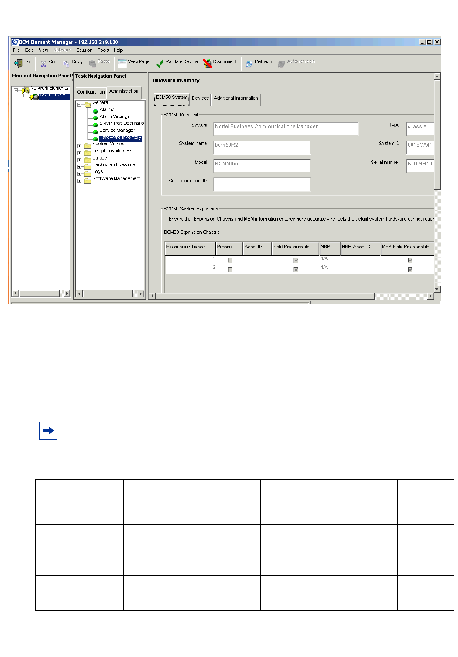
Chapter 7 Using the BCM50 Hardware Inventory 131
BCM50 Administration Guide
Figure 23 Hardware Inventory
Viewing and updating BCM50 system expansion information
The BCM50 system expansion area in the System tab provides information about the expansion
unit connected to the BCM main unit, if any. If an expansion unit is present and populated with an
MBM, this information is also provided.
Table 34 provides information about the fields in the BCM50 system expansion area.
Note: Asterisk (*) items can also be remotely queried by SNMP using the Entity
MIB.
Table 34 Expansion unit area and Fiber expansion media bay module area
Column Name Column Description Column Value Read/Write
Expansion Chassis Lists the number of the expansion
chassis.
1 or 2 Read
Present Indicates if an expansion unit to
main unit is present
Yes (if checked) Read
Asset ID* Customer defined tracking
number
Initially zero Write
Field Replaceable Indicates if the unit is considered
field replaceable by the
manufacturer.
True (if checked) Read

132 Chapter 7 Using the BCM50 Hardware Inventory
NN40020-600NN40020-600
To view or update BCM50 system expansion information
1In the BCM Element Manager, connect to a BCM50 device.
2Select Administration, General, Hardware Inventory.
The Hardware Inventory panel opens, and displays the BCM50 System tab.
3View the information displayed in the BCM50 System Expansion area .
4To update information about the expansion chassis, click the Present checkbox to indicate that
an expansion chassis is installed, and enter an ID in the Asset ID field.
5To update information about the media bay modules, enter an ID in the MBM Asset ID field.
Viewing and updating other information about the BCM50 system
The Other Information area in the System tab displays other information associated with this
particular BCM system, such as:
• the name of the administrator and their contact information
• the location of the BCM50 system
You can add or update this information. The date on which this information is updated is displayed
BCM50 area, in accordance with “LastChangeTime” of the Entity MIB.
Table 35 lists the fields displayed in the Other Information area.
MBM Use the drop-down menu to
identify the type of MBM, such as
whether it is a DSM16 or DSM32.
Drop-down menu Write
MBM Asset ID Enter the asset ID of the MBM. Numeric Write
MBM Field
Replaceable
Indicates if the unit is considered
field replaceable by the
manufacturer.
True (if checked)
Table 35 Other Information fields
Field Name Field Description Field Value Read/Write
Owner name The owner’s name or any other
information, such as the administrator’s
name and contact information
Up to 256 characters Write
Location of this
system
The location of the system Up to 256 characters Write
Last change to this
panel
Date and time when the information was
last modified
example ‘2004-04-16 09:
12:00”
Read
Table 34 Expansion unit area and Fiber expansion media bay module area
Column Name Column Description Column Value Read/Write

Chapter 7 Using the BCM50 Hardware Inventory 133
BCM50 Administration Guide
To view or update other information about the BCM50 main unit
1In the BCM50 Element Manager, connect to a BCM50 device.
2Select Administration, General, Hardware Inventory.
The Hardware Inventory panel opens. The BCM50 System tab is displayed.
3View the information displayed in the Other Information area.
4If you want to add or update information about the owner or administrator of the BCM50
system, enter information in the Owner Name field.
5If you want to add or update information about the location of BCM50 system, enter
information in the Location of the System field.
Viewing information about devices
The Devices tab displays information about all devices attached to the BCM50. These devices may
include:
• digital sets
• analog devices
• IP sets, including IP clients
You can view all Directory Numbers (DNs) and the type of set associated with the DN. Table 36
lists the fields in the Attached Devices table.
Note: DNs of type “Analog” are not necessarily be populated with a physical
telephone device.
Table 36 Attached Devices fields
Header Name Header Description Field Value Read/Write
DN Directory Number In accordance with DN numbering system Read
Model Type of device or set example T7316 or I2004 Read
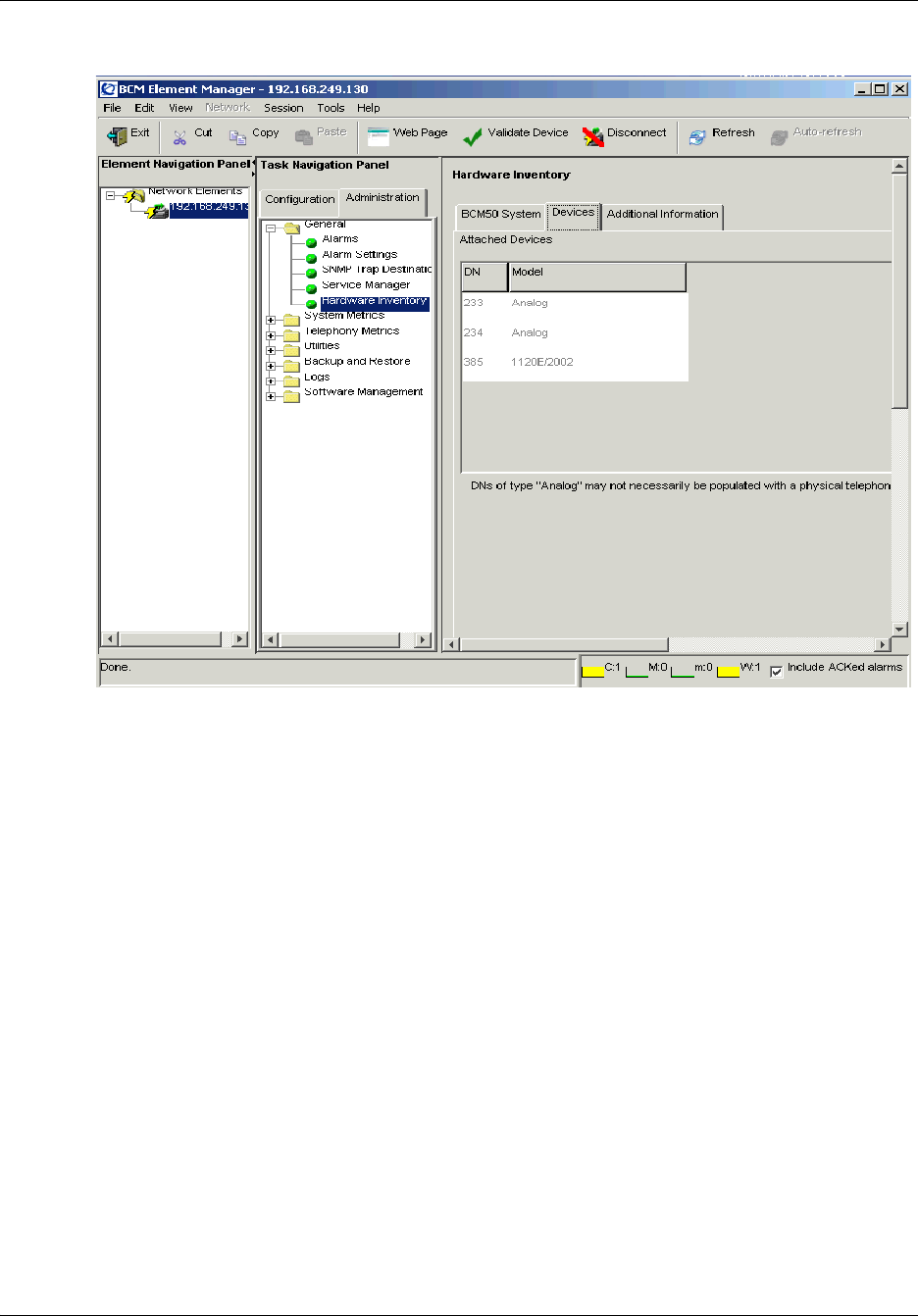
134 Chapter 7 Using the BCM50 Hardware Inventory
NN40020-600NN40020-600
Figure 24 Hardware Inventory Devices tab
To view information about attached devices
1In the BCM50 Element Manager, connect to a BCM50 device.
2Select Administration, General, Hardware Inventory.
The Hardware Inventory panel opens.
3Click the Devices tab.
4View the information displayed in the Attached Devices table.
Viewing additional information about the BCM50 hardware
inventory
The Additional Information tab displays additional information about the BCM50 main unit, such
as:
• details about the manufacturer and the manufacture date
• hardware version details
• serial number details
You require this information only when a field issue requires the identification of certain systems.

Chapter 7 Using the BCM50 Hardware Inventory 135
BCM50 Administration Guide
Table 37 lists the fields displayed in the Additional Information tab. Items marked as read-only are
detected by the BCM. For items that are not auto-detected, the Element Manager provides
checkboxes, pull-down menus, and fields that the administrator can populate to indicated that
these resources are present.
Note: Asterisk (*) items can also be remotely queried by SNMP using the Entity
MIB.
Table 37 Additional BCM50 main unit Information fields
Field Name Read/Write
Manufacturer* Read
Manufacture date Read
Manufacturing information Read
Hardware version* Read
CSC CPC Code Read
CSC serial number Read
CSC hardware version Read
Hard disk drive description Read
Hard disk drive PEC order code Read
Hard disk drive serial number Read
Hard disk drive firmware version Read
Router CDC CPC code Read
Router CDC PEC order code Read
Router CDC serial number Read
Router CDC hardware version Read
BRI CDC CPC code Read
BRI CDC PEC order code Read
BRI CDC serial number Read
BRI CDC hardware version Read
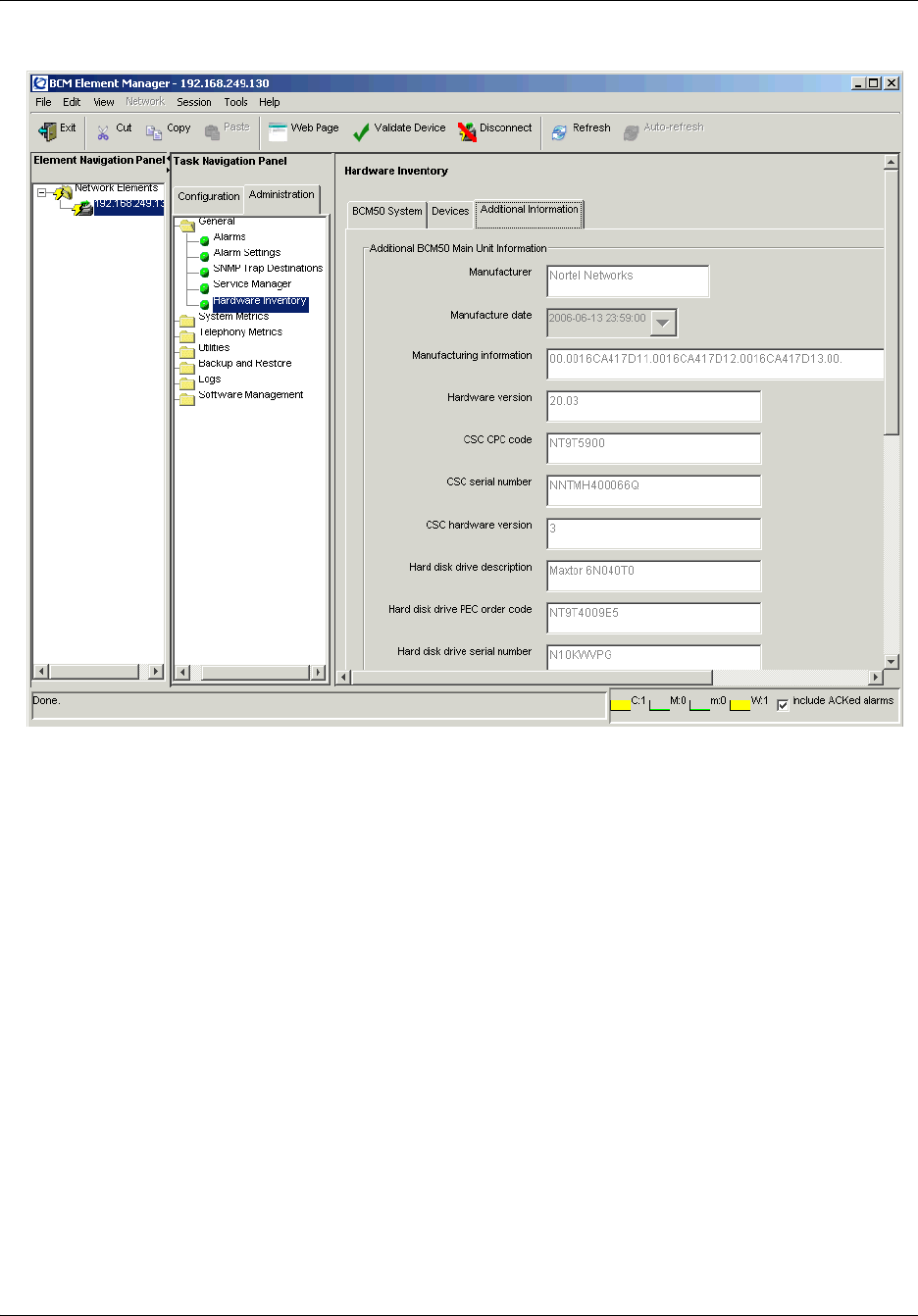
136 Chapter 7 Using the BCM50 Hardware Inventory
NN40020-600NN40020-600
Figure 25 Hardware Inventory Additional Information tab
To view additional information about the BCM50 hardware
inventory
1In the BCM50 Element Manager, connect to a BCM50 device.
2Select Administration, General, Hardware Inventory.
The Hardware Inventory panel opens.
3Click the Additional Information tab.
The Additional Information tab opens.
4View the information displayed in the Additional BCM50 Main Unit Information area.

137
BCM50 Administration Guide
Chapter 8
Managing BCM50 with SNMP
SNMP (Simple Network Management Protocol) is a set of protocols for managing complex
networks. SNMP-compliant devices, called agents, store meta-data in Management Information
Bases (MIBs) and provide this data to SNMP requesters.
You can use external SNMP clients, such as HP OpenView, to monitor the BCM50 system by
means of read-only SNMP requests.
This chapter provides information about:
• BCM50 support for SNMP
• configuring BCM50 SNMP settings
• using SNMP to send traps
Overview of BCM50 support for SNMP
This chapter provides information about SNMP support provided by the BCM50 main unit.
The BCM50 main unit supports the following versions of SNMP:
• SNMP v1 — the first implementation of SNMP; this version supports such protocols as IP
• SNMP v2C — provides improved efficiency and error handling
• SNMP v3 — provides improvements in security and privacy
Using the Element Manager, you can select which versions of SNMP you want the BCM50 agent
to support. For more information, see “Configuring SNMP settings”.
Management Information Bases provide access to the managed objects of a system and specify the
format of traps. BCM50 supports the following MIBs:
• RFC 1213 — MIB II
• RFC 2863 — Interface MIB
• RFC 2737 — Entity MIB
• RFC 2790 — Host MIB
• RFC 2261 — SNMP framework
• SmallSiteEvent MIB for traps
BCM50 units equipped with an integrated router (BCM50e, BCM50a, BCM50be, and BCM50ba)
also support RFC 1231 — MIB-II and a private MIB. For more information, see the BCM50
Networking Configuration Guide (NN40020-603).
For information about supported MIBs, how to install MIBs, and how to view SNMP traps, see
“Management Information Bases” on page 281.

138 Chapter 8 Managing BCM50 with SNMP
NN40020-600NN40020-600
BCM50 supports read-only SNMP requests, even for SNMP variables that display as read-write.
BCM50 does not support configuration operations through SNMP. Variables that are not
supported are displayed as “0”.
Configuring routers to use Element Manager with SNMP
Before you use the BCM for SNMP management, you must ensure that the BCM and the optional
integrated router are configured to allow SNMP queries to be received and responded to. You will
need to correctly configure NAT and Firewall settings for the router. For information on using the
router web-based interface to modify these settings, see the BCM50 Installation Guide and the
BCM50 Networking Guide. The sections below provide an overview of configuring the router to
enable SNMP management.
Connecting through the WAN
In this scenario, the LAN is configured as a private network with no public access. Before
beginning configuration, ensure that both the BCM50 and the SNMP Management Station are
working correctly. If you are using the BCM50a or BCM50e, only SNMPv1 is supported. If you
are using an external router, you can use those versions of SNMP supported by that router. To
enable SNMP, you must configure firewall settings, add NAT rules, and configure the SNMP port.
Configuring firewall settings
If the firewall is enabled on the router, several rules must be added so that the SNMP Management
Station and the BCM50 can communicate. If you are using a BCM50a or BCM50e, these settings
are configured in the Router manager. The first rule allows WAN to WAN communication:
• Source address: Management station’s IP Address, or “any”
• Destination address: Router’s WAN IP Address
• Service Type: SNMP (TCP/UDP: 163)
• Action: forward
The second rule allow WAN to LAN communication:
• Source address: Management station’s IP Address, or “any”
• Destination address: BCM50 LAN IP Address. This is the IP Address listed in Element
Manager under System/IP Subsystem/General Settings.
• Service Type: SNMP (TCP/UDP: 161)
• Action: forward
Adding NAT rules
In the NAT section of the router configuration, create a rule with the following settings:
• Start port: 161
• End port: 161

Chapter 8 Managing BCM50 with SNMP 139
BCM50 Administration Guide
• Server IP address: The BCM50 LAN IP address.
This rule means that all TCP/IP traffic to port 161, which is the BCM50’s SNMP agent port, will
be forwarded to the BCM50 for processing.
Configuring the SNMP router port
By default, both the BCM50 and the BCM50 router attempt to use port 161 for SNMP. This causes
a conflict. In the router configuration, access the Remote Management section, and the SNMP tab
to change this.
Change the communities to public, and set the SNMP Service Port to163. If the trap needs to be
enabled, set it to the SNMP management station IP address. Otherwise, set it to public.
The SNMP management station can now connect to the BCM50 LAN through port 161 and to the
router through port 163.
Connecting through the LAN
An SNMP management station that is configured on the LAN can access the BCM50 and Router
SNMP directly by using the LAN addresses of the BCM50 and BCM50 router.
An SNMP management station that is connected to the OAM LAN cannot access the router
SNMP, as there is no relay on the BCM50.
Configuring SNMP settings
You can use the Element Manager to configure the BCM50 SNMP agent. You can configure:
• general SNMP settings
• community strings
• service access points
• SNMP trap destinations
You can save a record of SNMP settings using the programming record. For more information, see
“Saving programming records” on page 59.
Configuring general SNMP settings
You can configure general SNMP settings, including:
• enabling and disabling the SNMP agent
• enabling and disabling versions of the SNMP agent
• defining access permissions
• adding and deleting SNMP management stations

140 Chapter 8 Managing BCM50 with SNMP
NN40020-600NN40020-600
You can create a list of SNMP managers who are permitted to query the BCM50 system by
specifying their IP addresses. If you have specified SNMP managers, the BCM50 SNMP agent
will respond only to SNMP requests from those IP devices.
To configure the BCM50 SNMP agent
1Start the Element Manager.
2In the Network Element navigation panel, select a BCM element.
3Log on to the BCM50 by clicking the Connect button.
4When the Element Manager has connected to the device, click the Configuration tab in the
Task panel.
5Open the Administrator Access folder, and then click SNMP.
6Click the General tab.
The General panel is displayed.
7Configure the SNMP Agent settings.
To configure BCM50 SNMP settings
1Click the Configuration tab.
2Open the Administrator Access folder, and then click SNMP.
3Click the General tab.
The General panel is displayed.
4In the SNMP Settings area, click the Modify button.
The Modify SNMP Settings dialog box opens.
Table 38 SNMP Agent Settings
Attribute Action
Engine ID The engine ID is the SNMP agent’s engine ID. This field is read-only and is for
information purposes only.
Port Number The port number is a read-only field that shows the SNMP agent’s local port number.
The port number is 161.
Chapter 8 Managing BCM50 with SNMP 141
BCM50 Administration Guide
5Configure SNMP settings.
The following combinations of SNMP versions are allowed:
— Option 1: SNMP v1, SNMP v2 and SNMP v3.
— Option 2: SNMP v3 only. This option provides more stringent security protection than
option 1 does.
— Option 3: SNMP v2 and SNMP v1.
6Click the OK button.
Adding an SNMP manager to the BCM50 SNMP manager list
To add an SNMP manager to the BCM50 SNMP manager list
1Click the Configuration tab.
2Open the Administrator Access folder, and then click SNMP.
3Click the General tab.
The General panel is displayed.
4In the SNMP Manager List area, click the Add button.
The Add Manager dialog box opens.
Table 39 Configure SNMP Settings Attributes
Attribute Action
Enable SNMP Agent Select whether to enable or disable the SNMP agent by selecting the check
box.
Minimum Required Security Select the minimum required security for SNMP. Options are: AuthNoPriv
or NoAuthNoPriv. Valid for SNMP v3.
SNMP Version Support Select the appropriate version from the drop-down list.
Note: If you configure an SNMP manager with an IP address of 0.0.0.0, the
SNMP agent will respond to SNMP queries from all stations.
Caution: If you add more than five SNMP management stations, the SNMP
service may degrade system performance.

142 Chapter 8 Managing BCM50 with SNMP
NN40020-600NN40020-600
5Configure the manager list attributes.
6Click the OK button.
To delete an SNMP manager
1Click the Configuration tab.
2Open the Administrator Access folder, and then click SNMP.
3Click the General tab.
The General panel is displayed.
4In the SNMP Manager List area, select a manager in the Manager IP Address table.
5Click the Delete button.
A confirmation message opens.
6Click the Ye s button.
The manager is removed from the Manager IP Address table.
Configuring SNMP community strings
An SNMP community string is a value, similar to a user ID or a password, that allows access to a
device's statistics. SNMP managers send a community string along with each SNMP request. If the
community string is correct, the BCM50 responds with the requested information. If the
community string is incorrect, the BCM50 discards the request and does not respond.
Community strings are used for SNMP v1 and v2C only.
BCM50 ships from the factory with community strings set. It is standard practice for network
managers to change all the community strings to prevent outsiders from seeing information about
the internal network. Before you can send SNMP messages to an SNMP workstation, you must
configure community strings.
Table 40 SNMP Manager Attributes
Attribute Action
Manager IP
Address
Enter the IP address of the SNMP manager that you want to authorize to query the
BCM50 system.
The IP address must correspond to the PC where the SNMP manager software is
installed. Do not use the dynamic IP address that the PC receives when the dial-up link
activates (when the BCM50 initiates dialing). Using the dynamic IP address causes the
removal of the required static route.
The format for the IP address is X.X.X.X:P, where P is the port.
Setting the IP address to 0.0.0.0 authorizes all SNMP managers to query the system.

Chapter 8 Managing BCM50 with SNMP 143
BCM50 Administration Guide
You can define the value of a community string, as well as the type of access. You can also delete
a community string.
To add a community string
1Click the Configuration tab.
2Open the Administrator Access folder, and then click SNMP.
3Click the Community Strings tab.
The Community Strings panel is displayed.
4Click the Add button.
The Add Community String dialog box is displayed.
5Specify the community string attributes.
6Click the OK button.
The community string is added to the Community Strings table.
To delete a community string value
1Click the Configuration tab.
2Open the Administrator Access folder, and then click SNMP.
3Click the Community Strings tab.
The Community Strings panel is displayed.
4In the Community Strings table, select the community string that you want to delete.
5Click the Delete button.
A confirmation message is displayed.
6Click Ye s .
The community string is removed from the Community Strings table.
Caution: Although there is no limit for the number of SNMP communities that
you can set, Nortel recommends that you limit the number of SNMP communities
to a maximum number of 5. Limiting the number of SNMP communities will
reduce degradation of system performance.
Table 41 SNMP Community String Attributes
Attribute Action
Community String Enter the entry name used as a key to uniquely identify an individual community entry
on the SNMP agent.
Type of Access Specify the read and write access for this community. Available options are Read Only
and Read/Write.

144 Chapter 8 Managing BCM50 with SNMP
NN40020-600NN40020-600
Configuring service access points
Service access points are associated with the enhanced security and privacy features of SNMP v3.
The Service Access Point tab is not visible if SNMPv3 is not selected on the SNMP General
Settings tab.
You can view and configure the following parameters associated with service access points.
• the user name associated with the service access point
• the authentication protocol
• the type of access
• the encryption protocol
• the authentication pass phrase
• the privilege pass phrase
You can add, modify, and delete service access points.
To add a service access point
1Click the Configuration tab.
2Open the Administrator Access folder, and then click SNMP.
3Click the Service Access Points tab.
The Service Access Points panel is displayed.
4Click the Add button.
The Add Service Access Point dialog box opens.
5Configure the Add Service Access Point attributes.
Table 42 Add Service Access Point Attributes
Attribute Action
User Name Enter the name of the user associated with the service access point.
Authentication
Protocol
Select the authentication protocol. Options are: None, MD5, SHA.
Type of Access Select the type of access. Options are: Read Only and Read/Write.
Encryption Protocol Select the encryption. Options are: None, DES, 3DES, AES.
Authentication Pass
Phrase
Enter the Authentication pass phrase for the service access point. Press
the Tab key when you have entered the phrase.
Privilege Pass Phrase Enter the Privilege pass phrase for the service access point. Press the Tab
key when you have entered the phrase.
Engine ID Enter an engine ID when you add a user that will be used for SNMP v3
communications. The engine ID is made up of hexidecimal digits with a
colon separating each digit.
Leave the engine ID blank when you add a user that will have access to the
MIB, or in the case of SNMP v3 MIB queries.

Chapter 8 Managing BCM50 with SNMP 145
BCM50 Administration Guide
6Click the OK button.
The service access point is added to the Service Access Point table.
To view details associated with a service access point
1Click the Configuration tab.
2Open the Administrator Access folder, and then click SNMP.
3Click the Service Access Points tab.
The Service Access Points panel is displayed.
4Select a service access point in the Service Access Points table.
Details are displayed in the Details pane.
To delete a service access point
1Click the Configuration tab.
2Open the Administrator Access folder, and then click SNMP.
3Click the Service Access Points tab.
The Service Access Points panel is displayed.
4In the Service Access Points table, select a service access point.
5Click the Delete button.
A confirmation dialog box opens.
6Click the Ye s button.
The selected service access point is deleted from the Service Access Points table.
Configuring SNMP trap destinations
An SNMP trap is a signal that tells the SNMP manager that an event has occurred on the system.
The SNMP system enables SNMP traps to be generated based on all or some events and alarms
generated on the BCM50 system. Any information that is displayed in the Alarms panel can
generate an SNMP trap. For information about the Alarms panel, see “Using the Alarms Panel” on
page 152.
BCM50 alarms that meet the SNMP trap criteria are forwarded to the SNMP trap reporting
interface according to defined trap community strings. SNMP trap notifications are displayed in
your SNMP trap software.
SNMP traps are generated by the BCM50 if you have enabled SNMP for specific BCM50 alarms.
You configure SNMP settings using the Alarm Settings task in the Element Manager.
You can configure the following attributes associated with a trap destination:
• the name of the trap destination
• the host address of the trap destination
•the port
• the SNMP version

146 Chapter 8 Managing BCM50 with SNMP
NN40020-600NN40020-600
• the community string (for SNMP v1 and v2C only)
• the user name (for SNMP v3 only)
For information about administering SNMP trap destinations, see “Viewing and modifying SNMP
trap destinations”.
To add a trap destination
1Click the Configuration tab.
2Open the Administrator Access folder, and then click SNMP.
3Click the SNMP Trap Destinations tab.
The SNMP Trap Destinations panel is displayed.
4Click the Add button.
The Add Trap Destination dialog box opens.
5Configure the Add Trap Destination attributes.
6Click the OK button.
The new trap destination is displayed in the Trap Destinations table.
Note: You can configure and administer SNMP trap destinations in both the
Configuration tab and the Administration tab of the Element Manager. This
allows operators who manage BCM50 faults to configure SNMP trap destinations
without having to access the SNMP settings on the Configuration panel. SNMP
must be enabled on the SNMP General panel if you want to configure and use
SNMP trap destinations from the SNMP Trap Destinations panel on
Administration panel.
Table 43 Add Trap Destination Attributes
Attribute Action
Name Enter a name for the trap.
Host Enter the IP address of the trap destination.
Port Enter the UDP port number from which the trap will be sent. The default
value is 162.
SNMP Version Select the version of the SNMP Agent for the trap. Options are: v1/v2C,
and v3.
Community String Enter the community string to use for the SNMP trap.
User Name For v3 only, enter the user name for the SNMP trap.
Note: When the SNMP agent is restarted, the System Uptime is reset. The SNMP
agent is restarted whenever you reboot the system, make an SNMP configuration
change, or enable/disable the SNMP agent.

Chapter 8 Managing BCM50 with SNMP 147
BCM50 Administration Guide
Viewing and modifying SNMP trap destinations
Once you have configured SNMP settings, you can view and administer SNMP trap destinations.
You can modify SNMP trap destinations.
To modify a trap destination
1Select Configuration>Administrator Access > SNMP > SNMP Trap Destinations or
Administration > General > SNMP Trap Destinations..
2In the Trap Destinations table, select a trap destination.
3Click the Modify button.
The Modify Trap Destination dialog box opens.
4Configure the Modify Trap Destination attributes.
5Click the OK button.
The modified trap destination is displayed in the Trap Destinations table.
Note: You can configure and administer SNMP trap destinations in both the
Configuration tab and the Administration tab of the Element Manager. This
allows operators who manage BCM50 faults to configure SNMP trap destinations
without having to access the SNMP settings on the Configuration panel. SNMP
must be enabled on the SNMP General panel if you want to configure and use
SNMP trap destinations from the SNMP Trap Destinations panel on
Administration panel.
Table 44 Modify Trap Destination Attributes
Attribute Action
Name Enter a name for the trap.
Host Enter the IP address of the trap destination.
Port Enter the UDP port number from which the trap will be sent. The default
value is 162.
SNMP Version Select the version of the SNMP Agent for the trap. Options are: v1/v2C,
and v3.
Community String Enter the community string to use for the SNMP trap.
User Name For v3 only, enter the user name for the SNMP trap.

148 Chapter 8 Managing BCM50 with SNMP
NN40020-600NN40020-600
Auto-SNMP dial-out
The auto-SNMP dial-out service allows you to use an analog modem or ISDN channel to deliver
alarms to a specified destination.
For information about how to configure a dial-up interface as a primary connection for
auto-SNMP dial-out, refer to the BCM50 Networking Configuration Guide (NN40020-603).
Alarm severity levels
The terminology used for alarm severity levels in the Alarms panel and in SNMP traps is not the
same. Table 45 lists Alarms panel terminology and the equivalent SNMP trap type.
While the BCM50 fault management system denotes the source of an alarm as “ComponentID”,
the SNMP system denotes the sources of this information as a trap of source “eventSource”.
Note: If the line is busy or if the modem cannot connect for any reason, the alarm
will not be delivered to the destination. If you are using SNMP v3, the modem
will re-attempt the connection three times.
Table 45 Terminology used for alarm severity levels
Alarm Banner SNMP Trap Type
Critical Error
Major Error
Minor Warning
Warning Information
Information Information

149
BCM50 Administration Guide
Chapter 9
Using the BCM50 Fault Management System
This chapter contains information about managing alarms generated by the BCM50 system and
administering alarm settings.
The chapter provides information about the following:
• an overview of BCM50 fault management tools
• an overview of BCM50 alarms
• alarms and log files
• administering alarms
• configuring alarm settings
• alarm severities
For a complete list of alarms generated by the BCM50 system, as well as information about
resolving the alarm, see the “List of BCM50 alarms” on page 287.
Overview of BCM50 fault management
You can view and manage real-time alarms generated by the BCM50 system. Alarms arise from
components that are running on the system; these alarms indicate faults or informational
conditions that may require resolution from the system administrator. Examples of alarm
conditions include:
• a T1 circuit on the system is down
• a service running on the BCM50 has been stopped by an administrator
Alarm information can be delivered to you by any of the following means:
• the Alarms Panel in the BCM50 Element Manager
• the Alarm Banner in the BCM50 Element Manager
• core telephony alarms show on the alarm set
• Simple Network Management Protocol (SNMP) traps for remote management of faults
• LEDs on the BCM50 main unit
You can manage alarms and alarm information by:
• configuring alarm settings, for example filtering alarms so that only the desired subset of
alarms are displayed in the BCM50 Element Manager Alarms Panel or sent as SNMP traps
• administering alarms, for example acknowledging selected alarms and clearing the alarm log
You can keep a record of alarm settings using the programming record. For information about
using the programming record, see “Saving programming records” on page 59.

150 Chapter 9 Using the BCM50 Fault Management System
NN40020-600NN40020-600
About BCM50 alarms
Alarms are generated by software components that are running on the BCM50 system, and cover
BCM50 services and applications.
Each component has a range of alarm IDs, so that each BCM50 alarm has a unique alarm ID.
Table 46 lists the components and the alarm ID ranges.
Table 46 BCM50 components and Alarm ID ranges
BCM50 Component Alarm ID Range
Core Telephony 0–999
Operating System 1000—1999
Software Updates 2000—2999
Persistent Data Repository 5000—5999
Date and Time 6000—6999
Modem Call Control 8000—8999
Service Manager 10000—10999
Platform Status Monitor 11000—11999
Backup and Restore 12000—12999
UPS 13000—13999
Configuration Change 16000—16999
System Set Based Admin 17000—17999
Startup Profile 19000—19999
System Authentication 30000—30999
Keycodes 31000—31999
Media Services Manager 40000—40999
CTE 41000—41999
Call Detail Recording 42000—42999
Voice CTI 43000—43999
Unistim Terminal Proxy Server 50000—50999
PVQM 50501—50999
VoIP Gateway 51000—51999
Media Path Server 52000—52999
Media Gateway Server 53000—53999
IP Telephony Provider 56000—56999
Survivable Remote Gateway 57000—57999
LAN Driver 60000—60999

Chapter 9 Using the BCM50 Fault Management System 151
BCM50 Administration Guide
Alarms and log files
All alarms that appear in the BCM50 Element Manager Alarms Panel are logged in the
alarms.systemlog file. This file is capped at 1 MB in size; when the file reaches this size, a new
alarms.systemlog file is started. The BCM50 keeps the current file as well as three previous files.
The file is also capped and a new file is started when the BCM50 system is rebooted.
You can retrieve the alarms.systemlog files (the current file plus the three previous files) from the
BCM50 system using the Log Management task in the BCM50 Element Manager. You can view
the files using the BCM50 Log Browser. For more information, see Chapter 15, “Managing
BCM50 Logs,” on page 245.
Alarm severities
Alarm severities are as follows:
By default, alarms are displayed in the Alarm Banner. The BCM50 sends SNMP traps for alarms
with a severity of Major and Critical. The only exception is PVQM alarms; for these alarms, the
BCM sends SNMP traps for all severity levels.
Table 48 provides the default mapping of each severity level against the Alarms Panel, alarms set,
LEDs, and SNMP.
Note: When you retrieve a log, a high level of CPU usage may occur. This level
of CPU is normal during a log retrieval operation.
Table 47 Alarm Severities
Alarm Severity Description
Critical Immediate corrective action is required due to conditions such as loss of
service, loss of bandwidth, outage, loss of data, and/or functionality
Major Urgent corrective action is required due to conditions such as pending loss
of service, outage, loss of data, and/or functionality
Minor Corrective action is required to prevent eventual service-affecting
degeneration
Warning Indicates the detection of a potential or impending service-affecting
condition and that some diagnostic action is required
Information Indicates audit-type information, such as configuration changes
Table 48 Default mapping of severity levels
Alarm Severity Alarms Panel LEDs SNMP
Alarm Set (core telephony
alarms only)
Critical Yes Yes Yes Yes
Major Yes Yes Yes Yes
Minor Yes No No No

152 Chapter 9 Using the BCM50 Fault Management System
NN40020-600NN40020-600
Administering alarms
Alarm information can be delivered to you by any of the following means:
• the Alarms Panel in the BCM50 Element Manager
• the Alarm Banner in the BCM50 Element Manager
• the alarm set (core telephony alarms only)
• Simple Network Management Protocol (SNMP) traps for remote management of faults
• LEDs on the BCM50 main unit
Using the Alarms Panel
You can view real-time alarm information using the Alarms Panel in the BCM50 Element
Manager. Each alarm has a unique identifier. Alarms are displayed in the Alarms table, sorted by
date and time by default, with the newest at the top of the table. The Alarms table displays from 50
to 400 alarms. For information about modifying the maximum number of alarms that are
displayed, see “Configuring alarm settings”.
The Alarms table contains the following elements:
• Time — the date and time of the alarm
• Alarm ID — the unique alarm ID associated with the alarm
• Severity — the severity of the alarm (Critical, Major, Minor, Warning, and Information)
• Problem Description — a description of the alarm condition
• Component ID — the process that has generated the alarm, in a 3-part DN format. The
component ID always identifies the system as a BCM, includes the name of the system that
generated the alarm, and identifies the component that generated the alarm. In this way, remote
monitoring stations can easily identify what type of system generated an SNMP trap and
which system generated the trap.
• Alarm Acked — indicates whether the alarm has been acknowledged in the BCM Element
Manager
When you select an alarm in the table, a Details panel is displayed for the selected alarm. The
Details panel displays the following information:
• Time — the date and time of the alarm
• Problem Description — a description of the alarm condition
• Problem Resolution — the course of action for the alarm
Warning Yes No No No
Information Yes No No No
Table 48 Default mapping of severity levels
Alarm Severity Alarms Panel LEDs SNMP
Alarm Set (core telephony
alarms only)

Chapter 9 Using the BCM50 Fault Management System 153
BCM50 Administration Guide
You can acknowledge an alarm to indicate that the alarm has been taken care of. You can specify
whether to include acknowledged alarms in the Alarm Banner so that the alarm count remains
concise. For more information about the Alarm Banner, see “Using the Alarm Banner” on page
154.
To view an alarm
When you view an alarm on the alarms panel, you can change the order of the columns in the table
and you can sort alarms. For example, you may want to sort alarms by Component ID and Alarm
ID.
1Click the Administration tab.
2Open the General folder, and then click the Alarms task.
The Alarms page opens.
3In the Alarms Panel table, select an alarm.
The Alarm Details panel displays below the Alarms table.
4To change the order of columns in the Alarm table, select a column and drag it left or right to
the desired location, and release it.
5To view a column by ascending or descending order, click the column heading.
6To sort columns, right-click a column heading.
The Sort dialog box opens.
7Sort columns as required, and then click the OK button.
The columns in the Alarm table are sorted according to your specifications.
To acknowledge an alarm
1Click the Administration tab.
2Open the General folder, and then click the Alarms task.
The Alarms panel opens.
3In the Alarms table, select the alarm you want to acknowledge.
The Alarm Details panel is displayed below the Alarms table.
4On the Alarms Details panel, click the Acknowledge Alarm button.
A check box appears in the Alarm ACKed column in the Alarms table for this alarm.
Acknowledging the alarm does not clear the alarm; it indicates only that the alarm has been noted.

154 Chapter 9 Using the BCM50 Fault Management System
NN40020-600NN40020-600
Clearing the alarm log
To clear the alarm log
1Click the Administration tab.
2Open the General folder, and then click the Alarms task.
The Alarms panel opens.
3On the Alarms panel, click the Clear Alarm Log button.
The Alarms table is cleared. Any new alarms will be displayed after the next alarm polling
interval.
Using the Alarm Banner
You can use the Alarm Banner in the BCM50 Element Manager to view current alarm counts and
recent alarm activity on the BCM50 system. The Alarm Banner appears on the bottom-right corner
of the BCM50 Element Manager window. The Alarm Banner is visible at all times, so you do not
have to navigate to the Alarms panel to view alarms. If you notice a change in alarm conditions in
the Alarm Banner — for example a red spike in the Critical category — you can navigate to the
Alarms Panel to view the actual alarm.
Caution: Clearing the alarm log clears the alarms in the Alarms Panel, as well as
from BCM memory. Therefore, alarms will no longer be available for viewing by
any other BCM Element Manager clients connected to the BCM. To view alarms,
access the Alarm log.
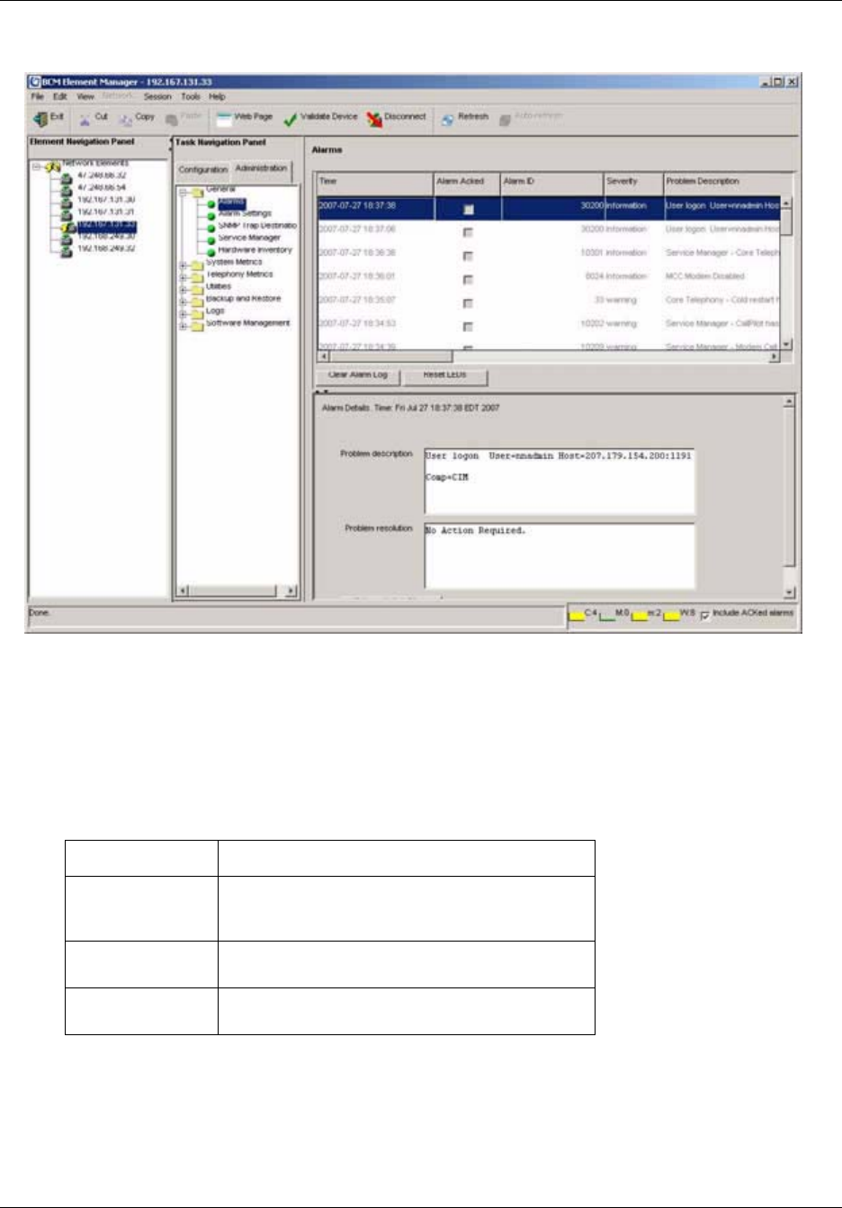
Chapter 9 Using the BCM50 Fault Management System 155
BCM50 Administration Guide
Figure 26 Alarm Banner
The Alarm Banner provides counts of Critical, Major, Minor, and Warning alarms; Information
alarms are not included. You can specify whether to include acknowledged alarms in the Alarm
Banner.
Each alarm severity counter has a graph, which represents a data sample of the last 20 polling
intervals. The graph has a color to indicate a data change. The colors are as follows:
The system polls for new alarms every 30 seconds by default.
If you clear the alarm log from the BCM50 Element Manager, the alarms displayed on the Alarm
Banner are also cleared and reset to 0.
Table 49 Alarm graph colors
Color Indicates
Green There are no alarms of this severity, or there are
alarms of this severity but the count has decreased
since the last polling interval.
Yellow There are alarms of this severity, but they are older
than at least 1 polling interval.
Red A new alarm has occurred since the last polling
interval.
156 Chapter 9 Using the BCM50 Fault Management System
NN40020-600NN40020-600
To include or omit acknowledged alarms in the Alarm Banner
Select or clear the Include ACKed Alarms check box in the Alarm Banner.
Using the alarm set
You can view core telephony alarms on a telephone set on the BCM50 system. This allows a
system administrator to monitor alarm activity without having a BCM50 Element Manager and a
personal computer.
You can specify the telephone to serve as the alarm set in the BCM50 Element Manager. The
telephone set used for alarms must have a 2-line display and three soft keys.
The alarm set displays an alarm as follows:
XXXXX-YYYY
Where XXXXX is the alarm ID and YYYY is additional alarm information.
The following options are available when an alarm is generated to the alarm set:
• Time — indicates the date and time when the alarm occurred
• Clear — use this soft key to remove the alarm from the alarm set.
Figure 27 shows an example of an alarm on the alarm set.
Note: Clearing an alarm from the alarm set does not change the status of alarms
on the BCM50 Element Manager or reset the LEDs on the front panel of the unit.
Note: When an alarm is dislayed on the alarm set, it remains visible until you
clear the alarm using a softkey on the alarm set. More recent alarms will not be
displayed until the current alarm is cleared on the alarm set.
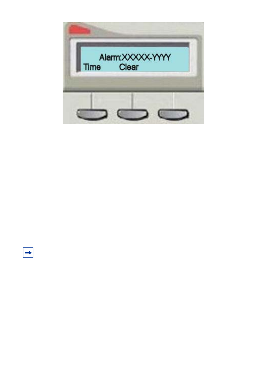
Chapter 9 Using the BCM50 Fault Management System 157
BCM50 Administration Guide
Figure 27 Alarm set alarm
To specify the alarm set
1Click the Configuration tab.
2Open the Telepho ny folder.
3Open the Global Settings folder, and then click the Feature Settings task.
The Feature Settings page opens.
4In the Feature Settings area, enter the DN of the telephone set that you want to use for the
alarm set in the Alarm Set field.
To clear an alarm from the alarm set
On the alarm set, press the Clear soft key. The alarm is cleared from the alarm set.
Alarms and LEDs
When an alarm condition occurs on the system, the Status LED on the front of the BCM50 main
unit changes to reflect the alarm condition. In normal operation, both LEDs are green. All alarms
with a severity of Major and Critical change the Status LED to solid red on the BCM50 front
panel, except in the event of a Failed Startup Profile, which is indicated by a flashing red LED.
Note: Clearing an alarm from the alarm set does not change the status of alarms
on the BCM50 Element Manager or reset the LEDs on the front panel of the unit.

158 Chapter 9 Using the BCM50 Fault Management System
NN40020-600NN40020-600
Using the BCM50 Element Manager, you can reset the Status LEDs on the front panel of the
BCM50 to a normal state.
To reset the Status LED
1Click the Administration tab.
2Open the General folder, and then click the Alarms task.
The Alarms panel opens.
3On the Alarms panel, click the Reset LEDs button.
The Status LED on the front panel of the BCM50 is reset from red to normal operation green.
Using SNMP traps
You can use an SNMP trap manager to remotely monitor BCM50 alarms via SNMP traps. A trap
is an indication from the BCM50 system to configured trap managers that an alarm has occurred in
the BCM50 system. Any BCM50 alarm can generate an SNMP trap.
If you want the BCM50 to send SNMP traps, you must first configure the SNMP agent using the
BCM50 Element Manager. You must enable an SNMP agent and then configure how the system
handles SNMP trap notifications. For information about configuring SNMP settings, see
“Configuring SNMP settings” on page 139.
The BCM50 system uses the Small Site Events Management Information Base (MIB) for alarms.
The trap format is specified in this MIB. You capture and view traps using any standard SNMP
fault monitoring framework or trap watcher. For information about the Small Site Events MIB, see
“Management Information Bases” on page 281.
By default, the BCM50 sends SNMP traps for alarms with a severity of Major and Critical. The
only exception is PVQM alarms; for these alarms, the BCM send SNMP traps for all severity
levels. You can change the default alarms that are set for SNMP to limit the volume and type of
SNMP information, and to control essential information that is transferred on the network. For
information about how to change the default alarms, see “To enable or disable SNMP traps for
alarms” on page 159.
Configuring alarm settings
Although the BCM50 system provides a default mapping of alarms that are displayed in the
Alarms table and that are sent as an SNMP trap, you may want to monitor additional alarms using
either of these means, or you may want to reduce the number of alarms that are displayed in the
Alarms table or sent via SNMP traps.You can specify how each alarm is handled, according to
your business requirements.
You can specify the following settings for alarms:
Note: Once the Status LED has changed to red in response to a Critical or Major
alarm condition, it remains in the alarmed state until you reset it using the BCM50
Element Manager.

Chapter 9 Using the BCM50 Fault Management System 159
BCM50 Administration Guide
• the maximum number of alarms to display in the Alarms Panel (from 50 to 400)
• whether to enable or disable SNMP traps for selected alarms; by default, all Critical and Major
alarms are sent as SNMP traps if you have specified one or more trap destinations
• whether to display selected alarms in the Alarms table; by default all Critical, Major, Minor,
and Warning alarms are displayed in the Alarms table
• whether to display selected alarms on the alarm set; by default, only core telephony Critical
and Major alarms are sent to this set
You can also test a selected alarm. This allows you to test whether the LED or SNMP traps are
functioning as expected. Testing an alarm generates an alarm in the system. Alarms generated
using the Test Alarm feature are identified in the Alarms table by the words “Test Event” in the
alarm Problem Description field.
For information about using SNMP to monitor the BCM50 system, see Chapter 8, “Managing
BCM50 with SNMP,” on page 139.
To enable or disable SNMP traps for alarms
1Click the Administration tab.
2Open the General folder, and then click the Alarm Settings task.
The Alarm Settings panel opens.
3In the Alarms table, select an alarm.
4In the Enable SNMP Trap column, select or clear the check box to enable or disable SNMP
traps for the selected alarm. If you select the check box for a selected alarm, an SNMP trap
will be generated if that particular alarm condition occurs.
To enable or disable viewing of selected alarms in the Alarms
table
1Click the Administration tab.
2Open the General folder, and then click the Alarm Settings task.
The Alarm Settings panel opens.
3In the Alarms table, select an alarm.
4In the Enable GUI View column, select or clear the check box to enable or disable a view of
the selected alarm in the Alarms Panel. If you clear the check box for a selected alarm, the
alarm will not be displayed in the Alarms table if that particular alarm condition occurs in the
system.
To view settings for the alarm set
1Click the Administration tab.
2Open the General folder, and then click the Alarm Settings task.
The Alarm Settings panel opens.
3In the Alarms table, select an alarm.

160 Chapter 9 Using the BCM50 Fault Management System
NN40020-600NN40020-600
4The Enable Alarm Set column indicates whether the alarm will display on the alarm set.
To test an alarm
1Click the Administration tab.
2Open the General folder, and then click the Alarm Settings task.
The Alarm Settings panel opens.
3In the Alarms table, select an alarm.
4Click the Test Al arm button.
In the Alarms table, “Test Event” is displayed in the alarm Problem Description field.
161
BCM50 Administration Guide
Chapter 10
Using the BCM50 Service Management System
You can use the Element Manager to view and administer the services that run on the BCM50
system.
This chapter provides:
• an overview the BCM50 service management system
• a list of BCM50 services
• information about how to start, stop, and restart BCM50 services
Overview of the BCM50 service management system
You can view details about the services that run on the BCM50 system, including:
• the name of a service
• whether a service is enabled to automatically start up
• the status of the service running on the BCM50
You can also administer services by starting, stopping, and restarting certain services.
You can keep a record of BCM50 services using the programming record. For more information,
see “Saving programming records” on page 59.
BCM50 services
Table 50 lists BCM50 services.
Caution: Use the BCM50 Services Manager only as directed by Nortel Technical
Support. Improper use of the BCM50 Services Manager may adversely affect
system operation.
Table 50 BCM50 Services
Service Name Description
BCMInventoryProvider Agent Cimom Provider
BCMPerfMonProviderAgent Cimom Provider
BCMSystemProviderAgent Cimom Provider
BCMUPSProviderAgent Cimom Provider
BCMWebProviderAgent Cimom Provider
BCM_DCMProviderAgent Cimom Provider

162 Chapter 10 Using the BCM50 Service Management System
NN40020-600NN40020-600
BCM_Doorphone Doorphone Service
BCM_HostProviderAgent Cimom Provider
BCM_IPMusicProviderAgent Cimom Provider
BCM_LicenseProviderAgent Cimom Provider
BCM_LogProviderAgent Cimom Provider
BCM_MIB2ProviderAgent Cimom Provider
BCM_SNMPProviderAgent Cimom Provider
BCM_SRGProviderAgent Cimom Provider
BCM_SecurityProvider Agent Cimom Provider
BCM_TimeServiceProviderAgent Cimom Provider
BCM_TimeZoneSettingProviderAgent Cimom Provider
BackupRestoreProviderAgent Cimom Provider
BriSW BRI software
CDRProviderAgent Cimom Provider
CDRService Call Detail Recording Service
CallPilotProviderAgent Cimom Provider
Core Tel Core Telephony
CoreTelProviderAgent Cimom Provider
Cte Computer Telephony Engine
DHCPProviderAgent Cimom Provider
DiaLogger System Logging Mechanism
Echo Server echo service
HGMetrics Reporter Hunt Group Metrics
IpTelProviderAgent Cimom Provider
LanCteProviderAgent Cimom Provider
LANProviderAgent Cimom Provider
Msm Media Services Manager
MsmProviderAgent Cimom Provider
NnuScheduler System Scheduler
Pdrd Persistence Data Repository Service
SoftwareUpdateProviderAgent Cimom Provider
SyslogListener Syslog Receiver
UftpServer UFTP Server
WANFailoverProvider Agent Cimom Provider
WANServiceMgr WAN Service
btraceserver Plug-in for Authentication and Routing Management for
BT
Table 50 BCM50 Services
Service Name Description

Chapter 10 Using the BCM50 Service Management System 163
BCM50 Administration Guide
To view details about services
1Start the BCM50 Element Manager.
2In the Element pane, select an element.
3Click the Connect button.
The Task pane is displayed.
4Click the Administration tab.
5Open the General folder, and then click the Service Manager task.
The Service Manager page opens. Services are displayed in the Services table.
core_file_monitor core file monitoring service
crond Cron Scheduler
cti server CTI service
feps Functional Endpoint Proxy Server (VoIP Gateway)
httpd HTTP Daemon
lms Line Monitor Server
mgs Media Gateway Server
modemcc modem service
mib2agt MIB II service
mps IP Telephony—Media Path
owcimomd Open Wbem Cimom Server Daemon
psm —
qmond QoS Monitor
securityservice Authentication and Authorization
srg SRG service
ssba System Set Based Admin Service (Feature 9*8)
sshd Secure Shell Daemon
tmwservice Time Service
utps UniSTIM Terminal Proxy Server (IP Sets)
voicemail Voicemail Process
Table 50 BCM50 Services
Service Name Description

164 Chapter 10 Using the BCM50 Service Management System
NN40020-600NN40020-600
Starting, stopping, and restarting services
You can stop any of the services that are running on the BCM50 system.
To stop a service
1Click the Administration tab.
2Open the General folder, and then click the Service Manager task.
The Service Manager page opens. Services are displayed in the Services table.
3In the Services table, select a service.
4Click the Stop button.
A confirmation dialog box opens.
5Click Ye s .
In the Services table, Stopped is displayed in the Status column for the stopped service.
To restart a service
1Click the Administration tab.
2Open the General folder, and then click the Service Manager task.
The Service Manager page opens. Services are displayed in the Services table.
3In the Services table, select a stopped service.
4Click the Restart button.
A confirmation dialog box opens.
5Click Ye s .
In the Services table, Running is displayed in the Status column for the restarted service.
Caution: Use the BCM50 Services Manager only as directed by Nortel Technical
Support. Improper use of the BCM50 Services Manager may adversely affect
system operation.

165
BCM50 Administration Guide
Chapter 11
Monitoring BCM50 System Metrics
You can use the Element Manager to view detailed information about the performance of the
BCM50 and about the performance of system resources. This chapter provides information about
using system metrics.
About the system metrics
Using the Element Manager, you can monitor overall system performance and other
performance-related information.
You monitor system status using the following tools:
• QoS Monitor
• UPS Status
• NTP Metrics
QoS Monitor
QoS Monitor monitors the quality of service (QoS) of IP trunk services. The tool periodically
monitors the delay and packet-loss of IP networks between two peer gateways. The main objective
of the QoS Monitor is to allow new IP telephony calls to fall back to the PSTN if the voice quality
of the IP network falls below the specified transmit threshold.
For information about setting the transmit threshold, see the BCM50 Networking Configuration
Guide (NN40020-603). You can set the threshold in the Element Manager in the Telephony
Resources panel.
Configuring the QoS Monitor
You configure the QoS Monitor using the QoS Monitor panel on the Administration tab. You can
configure the following:
• the monitoring mode
• logging parameters

166 Chapter 11 Monitoring BCM50 System Metrics
NN40020-600NN40020-600
To configure monitoring mode
1On the Navigation tree, click the Administration tab, System Metrics, and QoS Monitor.
2From the Monitoring Mode drop-down menu, select a monitoring mode.
Table 51 Monitoring Mode options
Attribute Action
Disabled —
Enabled in Link-Monitor Mode Continuously test the connection between the BCM50 and remote
endpoints.
Enabled in QoS-Monitor Mode Select this option if you want to calculate MOS values for each
endpoint, determine whether the connection has fallen below a
specific threshold, send MOS scores to FCAPS applications, and
create a log history of the MOS scores.
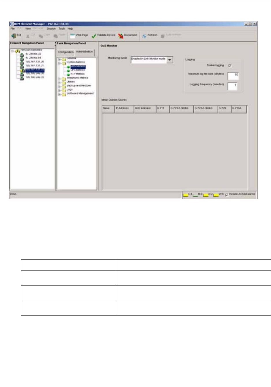
Chapter 11 Monitoring BCM50 System Metrics 167
BCM50 Administration Guide
Figure 28 QoS Monitoring mode
To configure logging attributes
1On the Navigation tree, click the Administration tab, System Metrics, and QoS Monitor.
2Configure logging attributes.
3Press the Tab key to save the settings.
Table 52 Logging attributes
Attribute Action
Enable Logging Enable the check box if you want to enable the logging of MOS
scores.
Maximum log file size Enter a value for the maximum size of the log file, from 1 to 10240
kilobytes (KB). The default is 10 KB.
Logging Frequency Enter the time interval between each MOS log: 1 to 1440 minutes.
The default is 1 minutes.

168 Chapter 11 Monitoring BCM50 System Metrics
NN40020-600NN40020-600
To view the QoS monitoring information
The Mean Opinion Scores table displays the current network quality described as a Mean Opinion
Score (MOS) for each IP destination. You can view the MOS mapping. Unlike the BCM 3.x where
both transmit and receive values were reported, the QoS Monitor collects only the transmit values.
Table 53 lists the fields displayed in the Mean Opinion Score table.
To refresh the QoS monitor data
To update the MOS table with the most current values, select View > Refresh, press F5, or select
the Refresh icon from the toolbar.
UPS Status
The BCM50 can support an Uninterruptible Power Supply (UPS) device to ensure continuous
operation during power interruption and failure conditions. The UPS feature provides power
source monitoring and battery backup so that critical system functionality required to maintain and
provide warning time to either correct the problem or to activate a contingency plan for impacted
services is possible. UPS is described in the BCM50 Installation and Maintenance Guide
(NN40020-302), and the BCM50 Installation Checklist and Quick Start Guide (NN40020-308).
Table 53 Mean Opinion Score descriptions
Attribute Description
Name Displays the name of the Remote Gateway
IP Address Displays the IP address of the Remote Gateway
QoS Indicator Displays a text description of the current MOS value. The MOS values can be Poor,
Fair, Good or Excellent.
G.711 Displays the current MOS value calculated when using a G.711 aLaw codec to
transmit VoIP packets to this Remote Gateway.
The MOS can be a value from 0.00 to 5.00, where 0.00 is the worst score (Poor)
and 5.00 is best score (Excellent).
G.723-5.3kbit/s Displays the current MOS value calculated when using a G.723 5.3 kbit/s codec to
transmit VoIP packets to this Remote Gateway.
The MOS can be a value from 0.00 to 5.00, where 0.00 is the worst score (Poor)
and 5.00 is best score (Excellent).
G.723-6.3kbit/s Displays the current MOS value calculated when using a G.723 6.3 kbit/s codec to
transmit VoIP packets to this Remote Gateway.
The MOS can be a value from 0.00 to 5.00, where 0.00 is the worst score (Poor)
and 5.00 is best score (Excellent).
G.729 Displays the current MOS value calculated when using a G.729 codec to transmit
VoIP packets to this Remote Gateway.
The MOS can be a value from 0.00 to 5.00, where 0.00 is the worst score (Poor)
and 5.00 is best score (Excellent).
G.729A Displays the current MOS value calculated when using a G.729A codec to transmit
VoIP packets to this remote Gateway.
The MOS can be a value from 0.00 to 5.00, where 0.00 is the worst score (Poor)
and 5.00 is best score (Excellent).

Chapter 11 Monitoring BCM50 System Metrics 169
BCM50 Administration Guide
The UPS connects and communicates with the BCM50 through USB. Enabling the UPS feature
requires plugging the UPS USB cable into the BCM50 USB connector before powering up the
BCM50. The UPS must be present during the boot up process for the BCM50 to function.
This section provides the procedure that describes how “To access UPS Status”.
To access UPS Status
1To access the UPS Status, open the Element Manager, click the Administration tab, click
System Status in the directory tree, and then click UPS Status.
The UPS Status then displays.
The UPS Status panel confirms that a UPS is connected including model and serial number, its
current status, and provides a read out of the current values. Additionally, an indication is
given whether the value is within the normal range or not.
The UPS Status panel tracks occurrences of alarms pertaining to UPS operation. These alarms are
also sequentially viewable in the Alarm panel. The metrics correspond to alarms in the BCM50
and appear in the alarm panel as well.
2To check the metrics of the UPS, click the Metrics tab. It displays the information on the
panel.
NTP Metrics
Using Network Time Protocol (NTP), you can configure the time on the BCM50 indirectly from a
single time server. NTP is a network protocol designed to synchronize the clocks of computers
over an IP network. The NTP Metrics provide an overview of the integrity of the NTP time source.
This section provides the procedure “To access the NTP Metrics”.
To access the NTP Metrics
1Open the Element Manager, click the Administration tab, click System Status and then
select NTP Metrics in the navigation tree.
2The NTP Metrics panel displays the following information:
Note: If the BCM50 clock control has not been configured to use NTP
(Configuration>System>Date & Time), then the NTP Metrics panel displays no
data.
Table 54 NTP Statistics
Parameter Name Description
Last Synchronized When the last synchronization occurred
Minimum time difference (s) The minimum time change that occurred since NTP was running

170 Chapter 11 Monitoring BCM50 System Metrics
NN40020-600NN40020-600
Maximum time difference (s) The maximum time difference that occurred since NTP was running
Last Synchronization Status The results of the last synchronization: successful or unsuccessful. If
unsuccessful the reason for the failure is given: failed to contact, or failed
security check. A status of Not Running indicates that NTP is not
configured.
Table 54 NTP Statistics
Parameter Name Description

171
BCM50 Administration Guide
Chapter 12
Monitoring BCM50 Telephony Metrics
You can use the Element Manager to view detailed information about the performance of the
BCM50 and about the performance of system resources.
This chapter provides information about telephony metrics.
Telephony Metrics
The following sections provide a general overview of the Element Manager Telephony Metrics.
The Telephony Metrics folder groups together a number of BCM50 system status tracking
different aspects of Telephony services.
This overview describes the following general process information:
•“Activity Reporter Basic” on page 171
•“Trunk Module Metrics” on page 172
•“CbC limit metrics” on page 178
•“Hunt Group Metrics” on page 180
•“PSTN Fallback Metrics” on page 182
•“Proactive Voice Quality Management” on page 183
Activity Reporter Basic
Activity Reporter Basic allows you to monitor the performance of the BCM. You can use the
Activity Reporter Basic to generate the following reports:
• telephone call activity
• custom call routing activity
• voice mail receive statistics
• hunt group performance
When you enable Activity Reporter Basic, the BCM automatically generates reports and updates
them each night. The reports reflect the performance of the BCM during the past four days. The
panel displays the date and time of the most recent report.
This section provides the following procedures:
•“To enable Activity Reporter Basic”
•“To disable Activity Reporter Basic”

172 Chapter 12 Monitoring BCM50 Telephony Metrics
NN40020-600NN40020-600
To enable Activity Reporter Basic
1In the Element Manager, select the Administration tab, then click the Telephony Metrics >
Activity Reporter Basic in the navigation tree.
The Activity Reporter Basic panel displays.
2Select the Enable Daily Data Collection checkbox to activate Activity Reporter Basic.
3In the Collection Time drop-down menu, select a time to generate daily reports. The default
time is 12:30 am.
To disable Activity Reporter Basic
1In the Element Manager, select the Administration tab, then click the Telephony Metrics >
Activity Reporter Basic in the navigation tree.
The Activity Reporter Basic panel displays.
2De-select the Enable Daily Data Collection checkbox to disable Activity Reporter Basic.
Trunk Module Metrics
When you need to find out information about a trunk module, you can determine the status of any
of the settings under the trunk modules headings. To correct a problem you may need to enable or
disable a port, a module, or an entire bus.
This section provides the following procedures:
•“To view Trunk Module status” on page 172
•“Disabling or enabling a B channel setting” on page 174
•“Provisioning a PRI B-channel” on page 174
•“Trunk Module CSU statistics” on page 175
To view Trunk Module status
The Trunk Module Metrics panel allows you to view the status of digital trunk modules as well as
identify any device or lines connected to the system. This allows you to isolate any malfunctioning
part of the system. In addition, you can use the Trunk Module selection to disable and enable
modules and devices.
Use this procedure to display module type, the number of sets connected to the module, the
number of busy sets and the module state:
1On the Element Manager navigation tree, select Administration > Telephony Metrics >
Trunk Module Metrics.
The window displays the expansion locations for the modules connected to the system.
2Select the module that you want to view. For example, Expansion 1. See Figure 29.
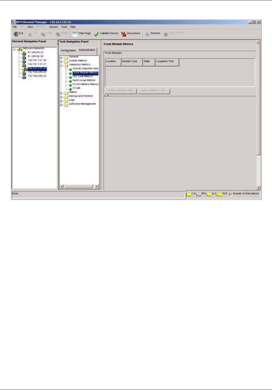
Chapter 12 Monitoring BCM50 Telephony Metrics 173
BCM50 Administration Guide
Figure 29 Viewing Trunk Module metrics
3Click Start Loopback Test button to start the network test without having to remove the
BCM50.
4Select a loopback type. The options are:
•payload
• line
• card edge
• continuity
5Click Stop Loopback Test when done the test of the network.
When you click on a module in the process above, a new menu appears, Details for Module:
<number> with the following tabs:
• CSU Alarms
• CSU Alarm History
• Performance
• Performance History
• D-Channel
• B-Channels

174 Chapter 12 Monitoring BCM50 Telephony Metrics
NN40020-600NN40020-600
Viewing Performance History information
The Performance History tab displays the performance information over 15-minute intervals
collected in the past 24 hours. The performance information collected includes the number of
errored seconds, severely errored seconds, and unavailable seconds over each 15-minute interval.
1On the navigation tree, click Administration, Telephony Metrics, Trunk Module Metrics.
2Click the Performance History tab to view metrics information.
Viewing D-Channel information
This tab displays trunk module metrics for the D-channel. D-channel metrics display when a BRI
trunk module is configured on the system.
1On the navigation tree, click Administration, Telephony Metrics, Trunk Module Metrics.
2Click the D-channel tab to view metrics information.
Disabling or enabling a B channel setting
If you need to isolate a problem, you may need to turn off individual port channels, rather than the
entire module.
To disable or enable a B channel setting
1On the navigation tree, click Administration > Telephony Metrics > Trunk Module
Metrics.
The window displays Expansion 1 or Expansion 2.
2Click heading of the bus you want to view. For example, click Expansion 1.
3Click the tab in the lower menu marked B-Channels.
4Click the B channel you want to enable or disable (B1 or B2).
5Then select Enable or Disable.
If you are disabling the channel, you are prompted by a dialog box to confirm your action. The
State field indicates the mode of operation for the port. If the port is enabled, this field is blank
unless a device is physically connected.
Provisioning a PRI B-channel
When you purchase PRI from your service provider, you can request the number of B-channels
that are allocated for you to use. For example, you may want to use only 12 B-channels. If you do
not have all of the PRI B channels, disable all the B-channels that you do not need.
Nortel recommends that the number of lines that are deprovisioned on a DTM (configured as PRI)
be the same as the number of B-channels that are disabled. For example, if the DTM is on
Expansion 1, when B-channels 13-23 are disabled, you should deprovision lines 77 to 87.

Chapter 12 Monitoring BCM50 Telephony Metrics 175
BCM50 Administration Guide
To provision a PRI B-channel
1Choose Administration, Telephony Metrics, Trunk Module Metrics.
2Choose an expansion module.
3Choose B channels.
A list of the B channels on this module appears.
4Click a channel, for example, B 01
The display shows the status of the PRI channel.
5On the Configuration menu, click Enable or Disable to change the setting for the channel.
Trunk Module CSU statistics
Each trunk module has an internal channel service unit (CSU). When enabled, the internal CSU
monitors the quality of the received T1 signal and provides performance statistics, alarm statistics,
and diagnostic information.
Trunk modules must be individually programmed to establish parameters for collecting and
measuring transmission performance statistics by the CSU.
For more information, refer to:
•“Statistics collected by the system” on page 175
•“Enabling the internal CSU” on page 176
•“To check the performance statistics” on page 176
•“To check the CSU alarms” on page 177
•“To check carrier failure alarms” on page 177
•“To check bipolar violations” on page 177
•“To check short-term alarms” on page 178
•“To check defects” on page 178
•“CbC limit metrics” on page 178
Statistics collected by the system
The system accumulates three performance parameters:
• errored seconds (ES)
• severely errored seconds (SES)
• unavailable seconds (UAS)
These parameters are defined according to TIA-547A. Errored seconds are enhanced to include
control slip (CS) events. Only near-end performance data is recorded.
The internal CSU continuously monitors the received signal and detects four types of transmission
defects:
• any active carrier failure alarms (CFA), such as loss of signal (LOS), out of frame (OOF),
alarm indication signal (AIS), and remote alarm indication (RAI)

176 Chapter 12 Monitoring BCM50 Telephony Metrics
NN40020-600NN40020-600
• the number of bipolar violations that occurred in the last minute
• any defects that occurred in the last minute, such as loss of signal (LOS), out of frame (OOF),
and alarm indication signal (AIS)
• the number of milliseconds of short-term alarms in the last minute, such as loss of signal
(LOS), out of frame (OOF), alarm indication signal (AIS), and remote alarm indication (RAI).
A short term alarm is declared when the detected defects persist for tens of milliseconds.
A carrier failure alarm (CFA) is a duration of carrier system outage. CFA types reported can be
mapped to CFAs defined in TIA-547A and TR62411 as shown in Table 55.
The criteria for declaring and clearing the alarms is selectable to meet those in TIA-547A or
TR64211. You can also view Carrier Failure Alarms as Core Telephony Alarms in the Alarm
Viewer.
Enabling the internal CSU
Use the following procedure to enable the internal CSU to gather performance statistics for your
T1 lines or PRI with public interface.
To enable the internal CSU
1Choose Configuration, Resources, Telephony Resources.
The window displays the expansion modules.
2Choose the appropriate expansion module. For example, select Expansion 1.
3For the selected module, choose the Trunk Module Parameters tab.
4In the T1 Parameters section, select the Internal CSU check box to enable the Internal CSU.
To check the performance statistics
1Choose Administration, Telephony Metrics, Trunk Module Metrics.
2Choose the appropriate expansion module that contains the module that you want to check.
3Choose Performance tab.
Table 55 Carrier failure alarms
Business Communications
Manager TIA-547A TR62411
LOS CFA RED CFA RED CFA
OOF CFA RED CFA RED CFA
AIS CFA RED CFA AIS CFA
RAI CFA YELLOW CFA YELLOW CFA

Chapter 12 Monitoring BCM50 Telephony Metrics 177
BCM50 Administration Guide
4The Current interval displays the duration of the current 15-minute interval of the selected
card, the number of errored seconds (ES), the number of severely errored seconds (SES) and
the number of unavailable time seconds (UAS).
5Click the 24-hour summary heading for an overall summary of the previous 24 hours.
The Number of intervals, Errored Seconds, Severely Errored Seconds, Unavailable Seconds
appear in the summary.
6Click the Reset Statistics button to reset any new settings.
The system displays a message indicating that this will remove all of the statistics.
7Select OK to erase all the current statistics and begin collecting statistics again.
Checking trunk module alarms
To check the CSU alarms
1Choose Administration, Telephony Metrics, Trunk Module Metrics.
2Choose an expansion module.
3Click the CSU Alarms tab.
The display shows all the active alarms of the types LOS (loss of signal), OOF (out of Frame),
RAI (Remote alarm indicator) or AIS (Alarm indication signal). For more information on
these types of transmission defects, refer to “Statistics collected by the system” on page 175.
To check carrier failure alarms
1Choose Administration, Telephony Metrics, Trunk Module Metrics.
2Choose an expansion module.
3Click the CSU Alarm History tab.
The display shows LOS (loss of signal), OOF (out of Frame), AIS (Alarm indication signal),
and RAI (Remote alarm indicator). For more information on these types of transmission
defects, refer to “Statistics collected by the system” on page 175.
4Choose the type of alarm you wish to view. For example, LOS (Loss Of Signal).
5Click the drop-down menu to select a time period.
The display shows the Start time of the period.
To check bipolar violations
1Choose Administration, Telephony Metrics, Trunk Module Metrics.
2Choose an expansion module.
3Click the CSU Alarms tab.
The display shows the number of bipolar violations that occurred in the last minute.

178 Chapter 12 Monitoring BCM50 Telephony Metrics
NN40020-600NN40020-600
To check short-term alarms
1Choose Administration, Telephony Metrics, Trunk Module Metrics.
2Choose an expansion module.
3Click the CSU Alarms tab.
The display shows the short term alarms and the number of milliseconds (not necessarily
contiguous) that were active in the last minute.
To check defects
1Choose Administration > Telephony Metrics > Trunk Module Metrics.
2Choose a an expansion module.
3Click the CSU Alarms tab.
The display shows the first type of defect and the number of milliseconds (not necessarily
contiguous) the hardware reported in the last minute.
To view CSU Alarm History
1Choose Administration, Trunk Modules.
2Choose an expansion module.
3Click the CSU Alarm History tab.
The display shows all the alarms
4To view a specific alarm, click the Alarm Name.
The display shows all the occurrences of that Alarm
CbC limit metrics
Call-by-call service (CbC) on public PRI protocol (NI-2) allows a PBX to use channels more
effectively by expanding or contracting the number of channels available to different call types
such as INWATS, OUTWATS, Foreign Exchange (FX), and tie lines.
The call-by-call service is a method of offering and receiving services to Customer Premises
Equipment (CPE) on ISDN PRI without the use of dedicated circuits (i.e. interface or B-channels).
The Call-By-Call service conveys signaling information over an ISDN Primary Rate Interface
(PRI) that indicates, on a per-call basis, the specific service type required to complete the call.
Although PRI-MCDN and IP trunks do not have multiple call types, CbC limits can be used on
these trunks to limit the number of incoming or outgoing trunks that may be in use simultaneously.
Once the feature is configured, use the CbC Limit metrics panel to monitor denied call activity for
each service on each line pool.
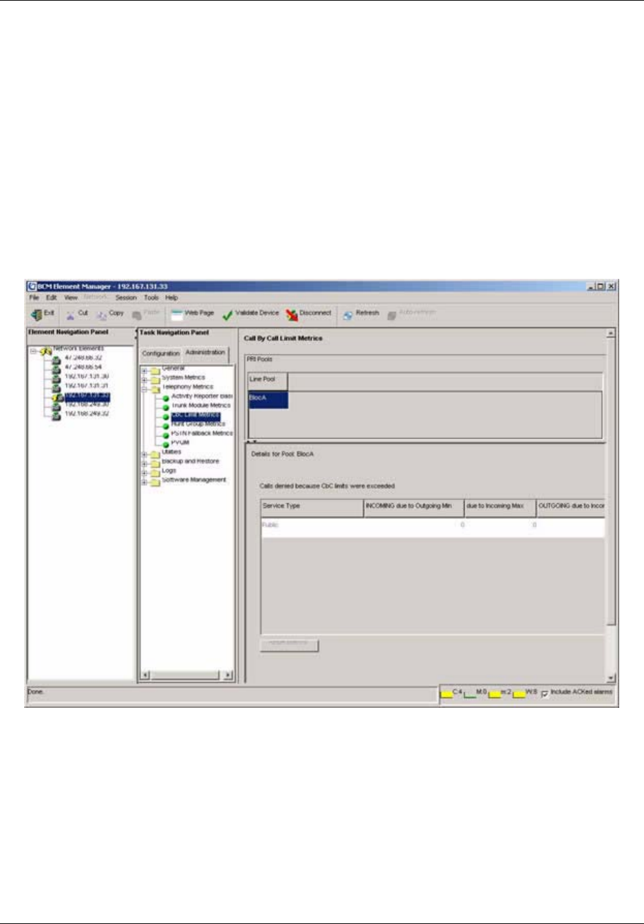
Chapter 12 Monitoring BCM50 Telephony Metrics 179
BCM50 Administration Guide
PRI lines that support call-by-call services have maximum and minimum call limits for each
service. Use this panel to view reports for the services. These limits are set as part of the
numbering plan programming.
This section provides the “To access the CbC limit metrics” procedure.
To access the CbC limit metrics
1To access the CbC metrics, in the Element Manager, click the Administration tab, click the
Telephony Metrics and then CbC Limit Metrics in the navigation tree.
2To assess the capacity of the PRI call services on your system, on the Call by Call Metrics
table, select the line pool for which you want to view CbC traffic. See Figure 30.
Figure 30 Call By Call limit metrics
The denied call details for each type of service supported by the line pool is displayed. See
Figure 31 on page 180.

180 Chapter 12 Monitoring BCM50 Telephony Metrics
NN40020-600NN40020-600
Figure 31 Denied calls details
Table 56 describes each field on the two CbC metrics panels.
Hunt Group Metrics
Hunt groups provide a service where incoming calls ring on a targeted group of telephones called a
Hunt group. When you designate a Hunt group, you define the group as a unique Directory
Number (DN). This DN receives and distributes calls to the telephones assigned to the group.
Table 56 Details for a Line Pool
Attribute Value
Call By Call Limit Metrics table
Line Pool Read-only. The pool of lines that call-by-call limits are applied
to.
Calls denied because CbC limits were exceeded table
Service Type Read-only. The type of service that the limits apply to.
INCOMING due to Outgoing
Min.
Read-only. The number of incoming calls that have been
blocked due to the call-by-call limits.
due to Incoming Max. Read-only. The number of incoming calls that have been
blocked due to the call-by-call limits.
Outgoing due to Incoming Min. Read-only. The number of outgoing calls that have been
blocked due to the call-by-call limits.
due to Outgoing Max. Read-only. The number of outgoing calls that have been
blocked due to the call-by-call limits.
Actions
Clear To clear the table so you can start a monitoring period:
1. Click on the Action menu item.
2. Select Clear.
3. Close the panel.
4. If you determine that the call denials are too numerous,
increase lines that support the affected service type.
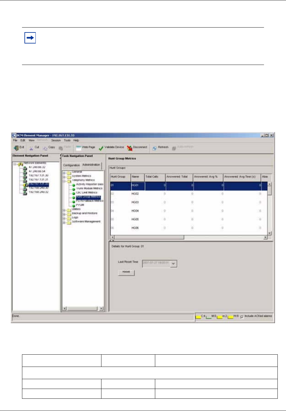
Chapter 12 Monitoring BCM50 Telephony Metrics 181
BCM50 Administration Guide
This section provides the procedure for “To access the Hunt Group metrics”.
To access the Hunt Group metrics
To access the Hunt Group metrics to evaluate total call processing by hunt group member:
1In the Element Manager, select the Administration tab, then the Telephony Metrics and
Hunt Group Metrics in the navigation tree. See Figure 32 on page 181.
Figure 32 Hunt Group Metrics Table
Table 57 describes each field on the panel.
Note: You can include Hunt Group hourly metrics files with the CDR data files
when the are transferred to the central server. For more information on
configuring this option, refer to the Call Detail Recording System Configuration
Guide (NN40020-605).
Table 57 Hunt Group Metrics fields
Attribute Value
Hunt Groups table
Hunt group name Read-only Name of hunt group
Name Read-only Name entered on DN record

182 Chapter 12 Monitoring BCM50 Telephony Metrics
NN40020-600NN40020-600
PSTN Fallback Metrics
When trunks are out of service, traffic can be switched to PSTN fallback lines. You can view how
many fallback attempts and fallback failures occur within a specific period using the PSTN
Fallback Metrics panel.
This section provides the procedure “To access PSTN Fallback metrics”.
To access PSTN Fallback metrics
1In the Element Manager, select the Administration tab, then click the Telephony Metrics and
PSTN Fallback Metrics in the navigation tree.
The PSTN Fallback metrics display immediately. See Figure 33 on page 183.
Total calls Read-only Total number of calls
Answered: Total Read-only Total number of answered calls
Answered Average% Read-only Average number of answered calls
Answered: Average time (s) Read-only Average answer time in seconds
Abandoned: Total Read-only Total number of abandoned calls
Abandoned: Average% Read-only Average number of abandoned calls
Busy: Total Read-only Total number of busy calls
Busy: Average% Read-only Average number of busy calls
Overflow: Total Read-only Total number of overflow calls
Overflow: Average% Read-only Average number of overflow calls
Time in Queue: Read-only Time in queue
Details
Last Reset time Read-only Time and date format depends country profile of
system.
Reset 1. On the Hunt Groups table, select the hunt group member for which
you want to reset the metrics.
2. In the lower frame, click the Reset button.
Table 57 Hunt Group Metrics fields (Continued)
Attribute Value
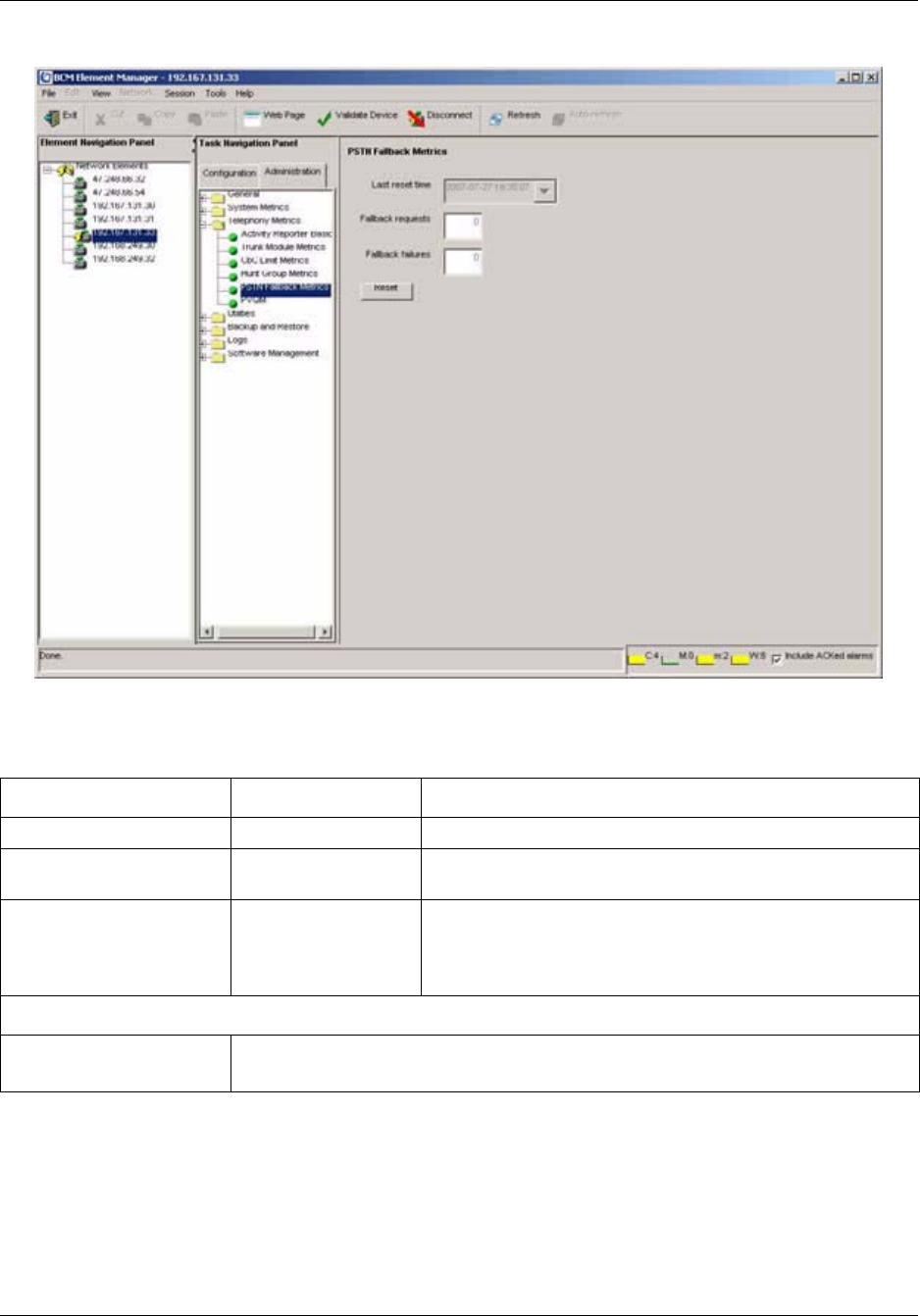
Chapter 12 Monitoring BCM50 Telephony Metrics 183
BCM50 Administration Guide
Figure 33 Fallback Metrics panel
Table 58 describes each field on the panel.
Proactive Voice Quality Management
Proactive Voice Quality Management (PVQM) metrics allow you to monitor the quality of VoIP
calls. You can also use the PVQM metrics to diagnose infrastructure problems in your network.
Table 58 PSTN Fallback Metrics fields
Attribute Value Description
Last reset time <read-only> This is the date and time the metrics table was last reset.
Fallback requests <read-only> The number of calls that were not able to route through the
preferred trunk.
Fallback failures <read-only> The number of calls that were not able to route through the
fallback trunk.
Note: If there is no fallback trunk assigned, all fallback
requests will fail.
Actions
Reset Click this button to clear out the metrics table.
The Last reset time will display the current date and time.

184 Chapter 12 Monitoring BCM50 Telephony Metrics
NN40020-600NN40020-600
You can use PVQM to configure and report threshold violations for the following voice quality
metrics:
• packet loss—packets lost in transit due to errors or network failures
• inter arrival jitter—the variable delay on a packet as it traverses a network
• round trip delay
• listening R—the transmission quality as experienced by the user; this metric reflects the
segment of the call that is carried over the RTP session
There are two thresholds for PVQM metrics: Warning, and Unacceptable. A violation of the
Warning threshold indicates that the voice quality is reduced but is still within an acceptable range.
A violation of the Unacceptable threshold indicates a severe degradation in voice quality.
PVQM is fully supported on Phase 2 IP sets. Phase 1 IP sets support only the following PVQM
metrics: packet loss, inter arrival jitter, and rould trip delay. Table 59 lists the IP Phones that
support PVQM.
This section provides procedures “To configure PVQM threshold settings” and “To access PVQM
metrics”, and also provides information about PVQM alarms.
To configure PVQM threshold settings
1In the Element Manager, select the Administration tab, then click the Telephony Metrics >
PVQM > Threshold Settings in the navigation tree.
The Proactive Voice Quality Monitoring panel displays. See Figure 33 on page 183.
Table 59 PVQM support
IP Set Type Description
IP Phone 2001 Phase 2 firmware
IP Phone 2002 Phase 1 and Phase 2 firmware
IP Phone 2004 Phase 1 and Phase 2 firmware
IP Phone 2050 v2 PC-based soft client
IP Phone 2007 Phase 2 firmware
IP Phone 1120E Phase 2 firmware
IP Phone 1140E Phase 2 firmware
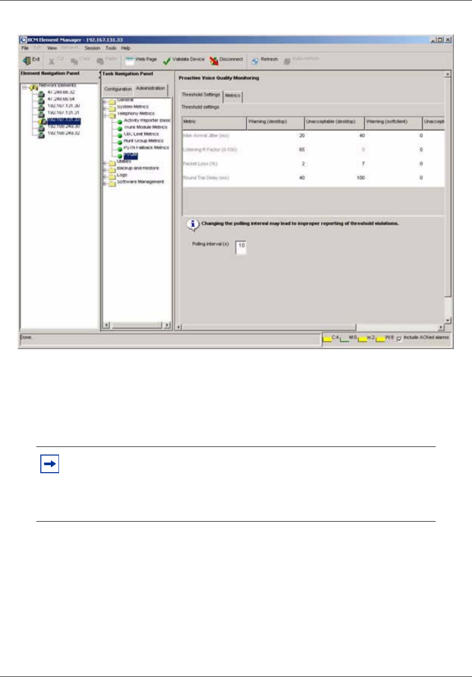
Chapter 12 Monitoring BCM50 Telephony Metrics 185
BCM50 Administration Guide
Figure 34 PVQM panel
2Configure the threshold value for each PVQM metric. The options are:
• warning (desktop)
• warning (soft client)
• unacceptable (desktop)
• unacceptable (soft client)
Note: The term “desktop” indicates IP sets that are desktop models. The term
“soft client” indicates IP sets that are software applications, such as the 2050 and
the 2050MVC. Since desktop IP sets may provide better voice quality than
software-based IP sets, you can specify different threshold levels for each type of
IP set.

186 Chapter 12 Monitoring BCM50 Telephony Metrics
NN40020-600NN40020-600
Table 62 describes the settings.
3Configure the polling interval.
PVQM alarms
If an alarm is generated to report a threshold violation, additional information is included in
the alarm to indicate the source of the alarm and provide other troubleshooting information.
Table 61 lists the abbreviations used in the alarm text to present this additional information.
Table 60 PVQM threshold settings
Metric Description Value Range
Default Value
for Warning
thresholds
Default Value
for
Unacceptable
thresholds
Packet Loss Rate The fraction of RTP data
packets from the source lost
since the beginning of the call,
expressed as a percentage.
0-100 1% 5%
Inter-arrival Jitter The inter-arrivak time of
incoming RTP packets, as
defined in RFC 1889.
Expressed in milliseconds.
0-1000 50 ms 500 ms
RTCP Round Trip
Delay
The round trip time of
incoming RTP packets, as
defined in RFC 1889.
Measured in milliseconds.
0-1000 300 ms 500 ms
Listening R Factor A scale from 0 (lowest quality)
to 100 (highest quality)
according to ITU-T G.107.
0-100 65 n/a
Table 61 PVQM alarm information
Abbreviation Attribute Value Description
cT codec type alphanumeric Vocoder type used on this call
eT endpoint type S or D S indicates softclient
D indicates desktop
nLR network loss rate percentage, scaled by
256 (e.g. 354 = 1.4%)
Rate of network packet loss
dR average discard rate percentage, scaled by
256
Average rate of discards due to jitter
bD burst loss density percentage, scaled by
256
Density of lost and discarded
packets during burst periods
bL burst length milliseconds Average length of bursts
gD gap loss density percentage, scaled by
256
Density of lost and discarded
packets during gap periods
gL average length of gap milliseconds average length of gap

Chapter 12 Monitoring BCM50 Telephony Metrics 187
BCM50 Administration Guide
For a list of the alarms generated by PVQM threshold violations, refer to About BCM50 alarms on
page 150 and List of BCM50 alarms on page 287.
To access PVQM metrics
1In the Element Manager, select the Administration tab, then click the Telephony Metrics and
PVQM > Metrics in the navigation tree.
The PVQM metrics panel displays.
eSD end system delay milliseconds Average end system delay on the
call
aNL noise level dBm Measured received silent period
noise level
aSP average signal level dBm Measured received signal level
during talk spurts
rTT local round trip time
average
1/65536 of a second Average round trip time on the call
Table 61 PVQM alarm information
Abbreviation Attribute Value Description
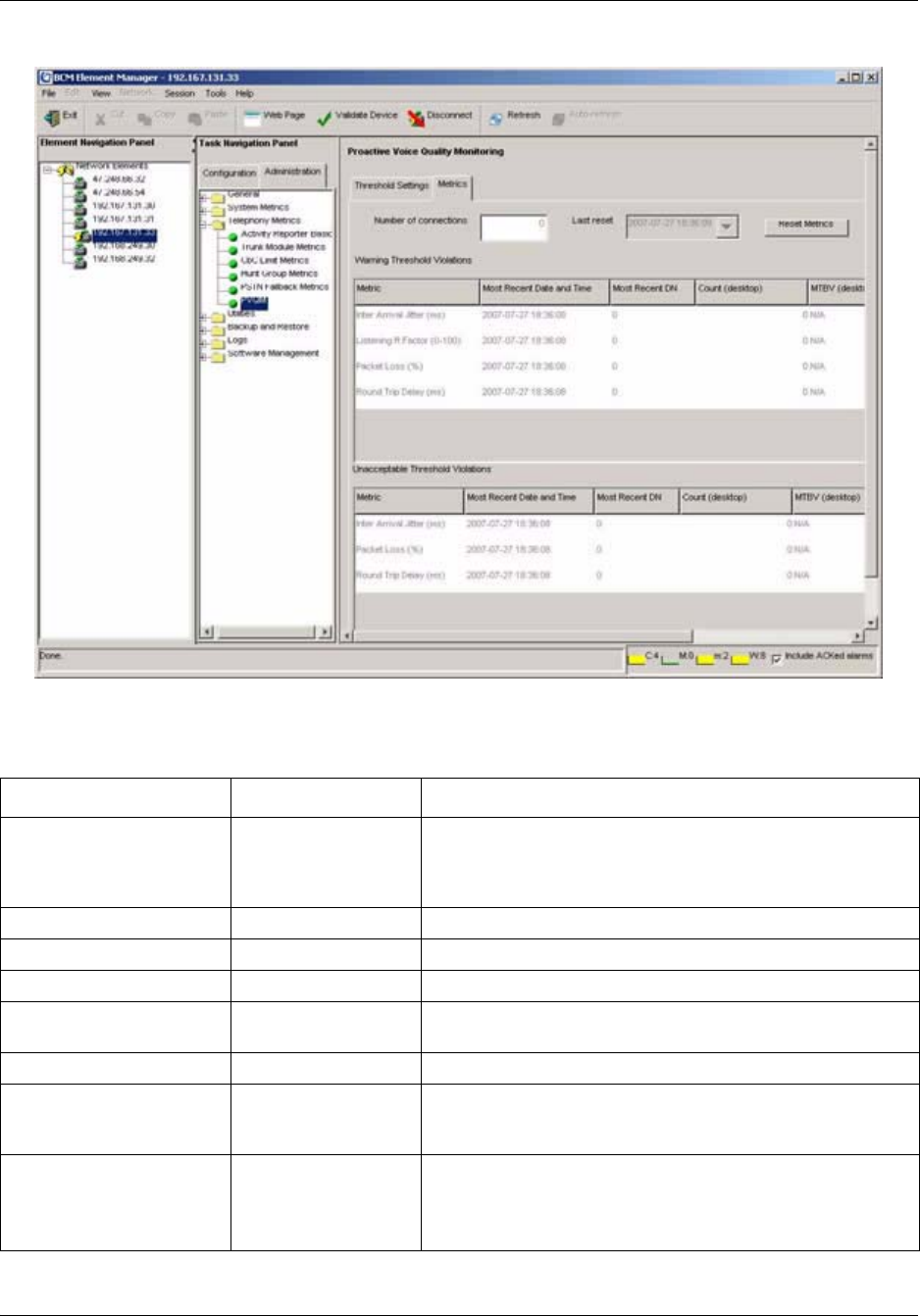
188 Chapter 12 Monitoring BCM50 Telephony Metrics
NN40020-600NN40020-600
Figure 35 PVQM Metrics panel
Table 62 describes each field on the panel.
Table 62 PVQM Metrics fields
Attribute Value Description
Number of connections <read-only> Displays the total number of connections by IP sets on the
system since the last reset. This count includes non-interactive
features such as dial tones, call progress tones, and music on
hold.
Last rest <read-only> Displays the time of the last reset.
Most recent date and time <read-only> Displays the time of the most recent threshold violation.
Most recent DN <read-only> Displays the DN of the most recent threshold violation.
Desktop count <read-only> Displays the number of times a desktop client violated a
threshold.
Soft client count <read-only> Displays the number of times a soft client violated a threshold.
Mean time between
violations (MTBV) for
desktop
<read-only> Displays the mean time between threshold violations of a
particular metric for desktop clients (measured in seconds).
Mean time between
violations (MTBV) for soft
client
<read-only> Displays the mean time between threshold violations of a
particular metric for soft clients (measured in seconds).

Chapter 12 Monitoring BCM50 Telephony Metrics 189
BCM50 Administration Guide
Actions
Reset Metrics Click this button to clear out the metrics table.
The Last reset time will display the current date and time.
Table 62 PVQM Metrics fields
Attribute Value Description

190 Chapter 12 Monitoring BCM50 Telephony Metrics
NN40020-600NN40020-600

191
BCM50 Administration Guide
Chapter 13
BCM50 Utilities
This chapter contains information about the utilities that are part of the Element Manager. These
utilities provide information about the BCM50 system, so that you can monitor and analyze
system status and performance.
BCM50 utilities are:
• BCM Monitor
•Ping
• Trace Route
• Ethernet Activity
• Reset
• Diagnostic Settings
About BCM Monitor
BCM Monitor is a stand-alone diagnostic application that the system administrator can use to view
real-time system and IP telephony information about BCM50 systems.
BCM Monitor is included with the installation of the Element Manager. You do not need to
download the utility, unless you are an administrative user who requires access to only this
management tool and you do not have or require the Element Manager.
Using BCM Monitor, you can monitor the following:
• overall system status
• IP telephony functions of the BCM50 system, including IP device activity and VoIP session
information
• utilization of resources
• operation of telephony applications (for example, Voice Mail and Contact Center)
• lines
• PRI, BRI, and IP trunks
You use BCM Monitor from a remote PC that has IP connectivity to the monitored system. You
can open multiple instances of BCM Monitor on a single PC to monitor several remote BCM50
systems at the same time.
BCM Monitor supports BCM50 release 2.0 and later. You can use BCM Monitor with BCM
releases 2.5 and 2.5 FP1, but these releases provide only limited support for certain diagnostic
queries and unsupported information elements appear as “N/A” in BCM Monitor panels.
When BCM Monitor connects to a BCM system that does not support a particular information
element, this is indicated by “N/A” in the relevant BCM Monitor panels.
BCM Monitor does not require significant hard disk space or memory on the client PC.

192 Chapter 13 BCM50 Utilities
NN40020-600NN40020-600
The following operating systems support BCM Monitor:
• Windows Vista (Business, Ultimate, and Enterprise versions)
• Windows 2000
•Windows XP
• Citrix
Installing BCM Monitor
BCM Monitor is included with the installation of the BCM50 Element Manager. You do not need
to download and install the utility separately, unless you are an administrative user who requires
access to only this management tool and you do not have or require the BCM50 Element Manager.
If you do require BCM Monitor separately from the Element Manager, you install the application
from the BCM50 Web page.
To install BCM Monitor separately from BCM50 Element Manager
1On the BCM50 Web Page, click the Administrator Applications link.
The Administrator Applications page opens.
2Click the BCM Monitor link.
The BCM Monitor page opens.
3Click the Download BCM Monitor link.
4Select a folder where you want to store the BCM Monitor install file, and then click the Save
button, or click the Run button to run the install file directly from the web page.
5If you selected Save in step 5, go to the folder where you saved the BCM Monitor install file,
and then double-click the BCMMonitor.exe icon.
6Follow the instructions on the installation wizard.
To remove BCM Monitor
1In Windows, click the Start button.
2Select Control Panel.
3Double-click the Add or Remove Programs icon.
4Select BCM Monitor, and then click the Change/Remove button.
5Follow the on-panel removal instructions.
Connecting to a BCM50 system
For security reasons, the user on the computer on which the BCM Monitor runs must be
authenticated by the BCM50 system.
Chapter 13 BCM50 Utilities 193
BCM50 Administration Guide
To start BCM Monitor without the Element Manager
1Double-click the BCM Monitor shortcut on your desktop or find BCM Monitor in your
Start/Programs menu.
The Enter Logon Information window opens.
2In the System Name or IP Address field, enter the system name of the BCM50 you want to
monitor.
3In the Connect As field, enter your BCM50 user name.
4In the Password field, enter the password associated with your BCM50 user name.
5Click the Connect button.
The BCM Monitor panel opens.
To start BCM Monitor from the Element Manager
1Click the Administration tab.
2Open the Utilities folder, and then click BCM Monitor.
The BCM Monitor panel opens.
3Click the Launch BCM Monitor button.
BCM Monitor opens and connects to the same BCM50 that the Element Manger is currently
connected to.
Disconnecting BCM Monitor from a BCM50
On the File menu of the BCM Monitor, select Disconnect from BCM.
BCM Monitor disconnects from the BCM50 system and clears all the fields.
To connect to a different BCM50
1On the File menu of the BCM Monitor, select Disconnect from BCM.
BCM Monitor disconnects from the BCM50 system and clears all fields.
2On the File menu of the BCM Monitor, select Connect to BCM.
The Enter Logon Information window opens.
3In the System Name or IP Address field, enter the system name of the BCM50 you want to
monitor.
4In the Connect As field, enter your BCM50 user name.
Note: You can also launch the BCM Monitor from within the Element Manager
by selecting Tools > BCM Monitor.
Note: If you do not want to connect to another BCM50 system, close the BCM
Monitor application. This terminates the application and disconnects BCM
Monitor from the BCM50 system.

194 Chapter 13 BCM50 Utilities
NN40020-600NN40020-600
5In the Password field, enter your password.
6Click the Connect button.
The BCM Monitor panel opens.
Using BCM Monitor to analyze system status
System Administrators and support personnel can use BCM Monitor to obtain real-time
troubleshooting data about the BCM system and to save data to generate system utilization and
traffic reports.
BCM Monitor tabs provide information about the following:
• the overall BCM50 system
• utilization of resources
• operation of telephony applications (for example, Voice Mail, and Contact Center)
• lines
• PRI, BRI, and IP trunks
You can capture information about the BCM50 system by using:
• static snapshots
• dynamic snapshots
Static snapshots
You can capture an instantaneous snapshot of system information in a text file. You specify which
BCM Monitor tab you want to capture and then save the information to the .txt file. The file name
embeds the time, date, and BCM50 name information so that you can view the data using
Microsoft Word or another application at another time.
Before you start a snapshot, you must configure static snapshot settings.
To configure static snapshot settings
1On the File menu, select Snapshot Settings.
The Snapshot Settings panel opens.
2Click the Static Snapshot Settings tab.
3In the Path and Filename area, enter the filename for the static snapshot in the Output
Filename field. For additional options, click the Arrow button to the right of the Output
Filename field.

Chapter 13 BCM50 Utilities 195
BCM50 Administration Guide
4Configure the Output Filename attributes.
5In Output Folder field, enter the path of the folder where you want to store static snapshots.
To browse for a folder, click the ... button to the right of the Output Folder field.
The Browse for Folder dialog box opens.
6Select a folder or make a new folder, and then click the OK button.
Table 63 Output filename attributes
Attribute Action
Auto-Increment Counter Automatically increments the filename so that subsequent files do not
overwrite earlier files. Adds <counter> to the filename in the Output
Filename field.
BCM Name Adds the name of the BCM to the filename. Position your cursor in the
filename field where you want the name to be added. Adds <BCM name>
to the filename in the Output Filename field.
Time Adds the time to the filename. Position your cursor in the filename field
where you want the name to be added. Adds <time> to the filename in the
Output Filename field.
Date Adds the date to the filename. Position your cursor in the filename field
where you want the name to be added. Adds <date> to the filename in the
Output Filename field.
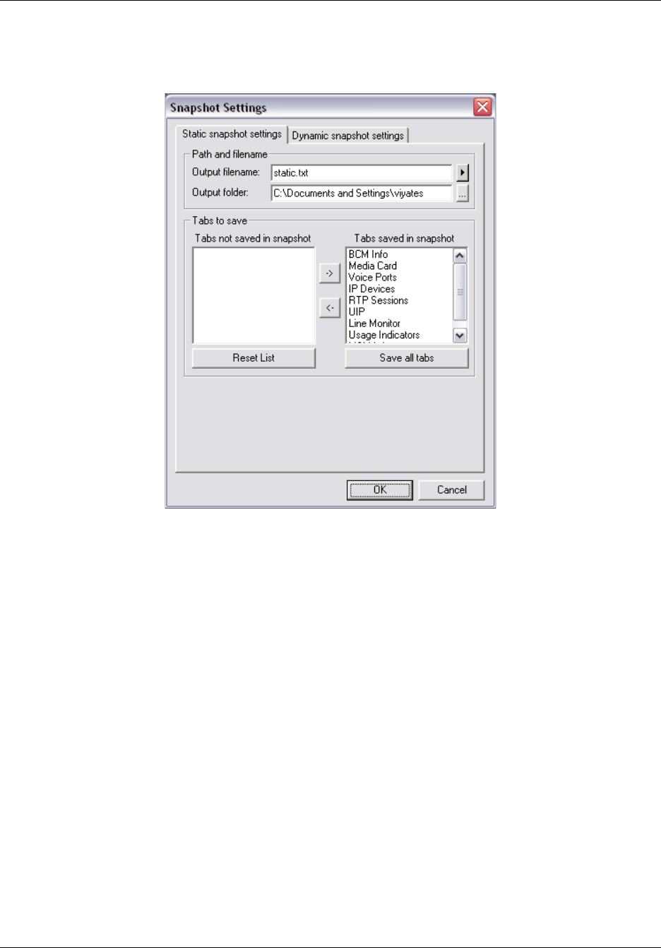
196 Chapter 13 BCM50 Utilities
NN40020-600NN40020-600
7Select the BCM Monitor tabs that you want to include in static snapshots in the Tabs Saved in
Snapshot box. For example, if you want snaphots to include information about voice ports,
make sure that Voice Ports is included in the Tabs Saved in Snapshot box.
8To remove tabs from the snapshots definition, select a tab from the Tabs Saved in Snapshot
box and use the arrow button to move the tab to the Tabs Not Saved in Snapshot box.
9Click the OK button.
To save a static snapshot
Once you have configured static snapshot settings, you can save static snapshot at any time.
1While you are observing data on a tab, select Save Static Snapshots from the File menu, or
press CTRL S.
All the tabs included in the snapshot definition are saved to a text file located in the folder you
specified when you configured the static snapshot settings.
Dynamic snapshots
Dynamic snapshots record snapshots of system data that changes over time, such as CPU
utilization and active calls. Dynamic snapshots are captured according to a frequency that you
define. Once dynamic snapshots are enabled, BCM Monitor saves dynamic snapshot information
to a file on your personal computer, using the comma separated value (csv) file format. You can
open this file using a spreadsheet application, such as Microsoft Excel.

Chapter 13 BCM50 Utilities 197
BCM50 Administration Guide
You can:
• specify which information you want to dynamically log
• enable or disable automated dynamic snapshots
• specify the interval of time between successive snapshots
Time intervals are specified in seconds. You can specify a maximum number of snapshots or
infinite logging.
To configure dynamic snapshot settings
1On the File menu, select Snapshot Settings.
The Snapshot Settings panel opens.
2Click the Dynamic Snapshot Settings tab.
3In the Path and Filename area, enter the filename for the dynamic snapshot in the Output
Filename field. For additional options, click the Arrow button to the right of the Output
Filename field.
4Configure the Output Filename attributes.
5In Output Folder field, enter the path of the folder where you want to store the static
snapshots. To browse for a folder, click the ... button to the right of the Output Folder field.
The Browse for Folder dialog box opens.
6Select a folder or make a new folder, and then click the OK button.
Table 64 Output filename attributes
Attribute Action
Auto-Increment Counter Automatically increments the filename so that subsequent files do not
overwrite earlier files. Adds <counter> to the filename in the Output
Filename field.
BCM Name Adds the name of the BCM to the filename. Position your cursor in the
filename field where you want the name to be added. Adds <BCM name>
to the filename in the Output Filename field.
Time Adds the time to the filename. Position your cursor in the filename field
where you want the name to be added. Adds <time> to the filename in the
Output Filename field.
Date Adds the date to the filename. Position your cursor in the filename field
where you want the name to be added. Adds <date> to the filename in the
Output Filename field.
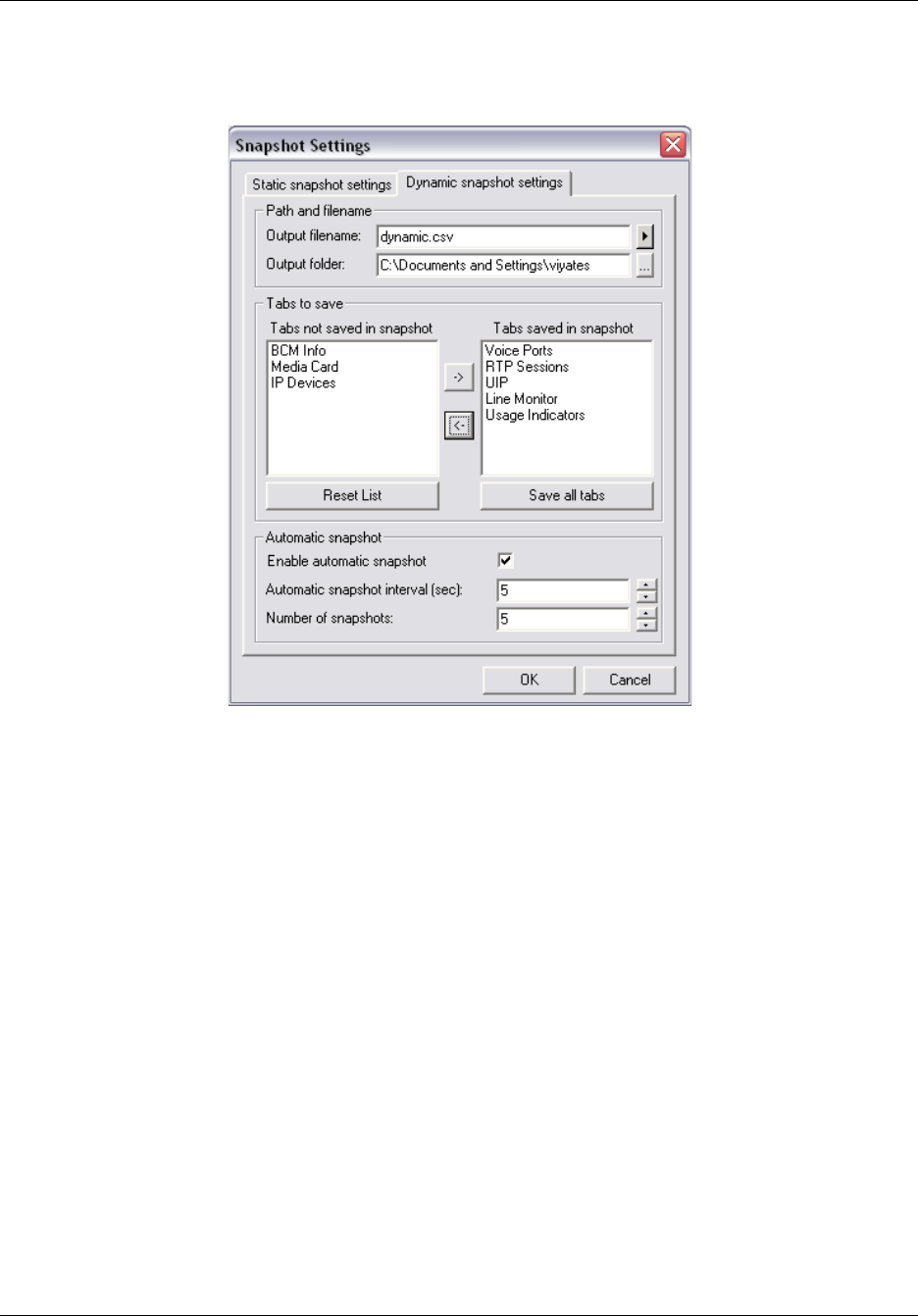
198 Chapter 13 BCM50 Utilities
NN40020-600NN40020-600
7Select the BCM Monitor tabs that you want to include in dynamic snapshots in the Tabs
Saved in Snapshot box. For example, if you want the snapshots to include information about
voice ports, make sure that Voice Ports is included in the Tabs Saved in Snapshot box.
8To remove a tab from the snapshots, select a tab from the Tabs Saved in Snapshot box and
use the arrow button to move the tab to the Tabs Not Saved in Snapshot box.
9In the Automatic Snapshot area, click the Enable Automatic Snapshot check box to enable
automatic snapshots. If you disable automatic snapshots, BCM Monitor will take a single
snapshot instead of a series of snapshots. If you enable automatic snapshots, the Automatic
Snapshot Interval (sec) field and the Number of Snapshots field become available.
10 In the Automatic Snapshot Interval (sec) field, enter the interval in seconds between
successive automatic snapshots.
11 In the Number of Snapshots field, enter the number of snapshots from 1 to Infinite.
12 Click the OK button.
Starting a dynamic snapshot
Once you have configured dynamic snapshot settings, you can start a dynamic snapshot. Once you
start dynamic logging, BCM Monitor continues taking snapshots until it reaches the number of
snapshots you defined when you configured dynamic snapshot settings, or until you stop a
dynamic snapshot.
When you start dynamic snapshots, the BCM Monitor status bar displays “Dynamic snapshot
active” on the status bar at the bottom of the panel.
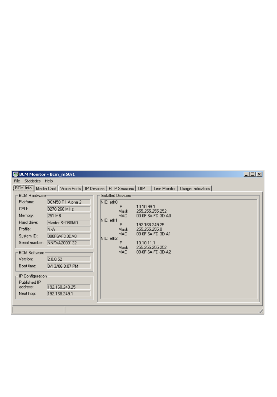
Chapter 13 BCM50 Utilities 199
BCM50 Administration Guide
On the File menu, select Dynamic Snapshot, Start.
BCM Monitor starts taking snapshots and saves the snapshot data in a file located in the folder you
specified when you configured the dynamic snapshot settings.
Stopping a dynamic snapshot
On the File menu, select Dynamic Snapshot, Stop.
BCM Info tab
The BCM Info tab displays static information about the BCM50 system, such as:
• information about the main hardware components of the BCM50 system
• software installed on the system
• IP configuration data
You can use the information on this tab to verify the software release level of the BCM50, the
published IP address and default gateway of the BCM50 main unit, the last time the BCM50 was
rebooted, as well as IP address information about other Ethernet interfaces on the BCM50 main
unit.
The installed devices on the BCM50 Info tab are displayed as follows:
• Eth0 — indicates a LAN internal to the BCM50 system.
• Eth1 — indicates a customer LAN. This is the LAN accessible to the customer through ports
1, 2 and 3 on the front panel of the BCM50 main unit.
• Eth2 — OAM LAN. This is a dedicated OAM port accessible as port 0, the left-most Ethernet
port on the front panel of the BCM50 main unit.
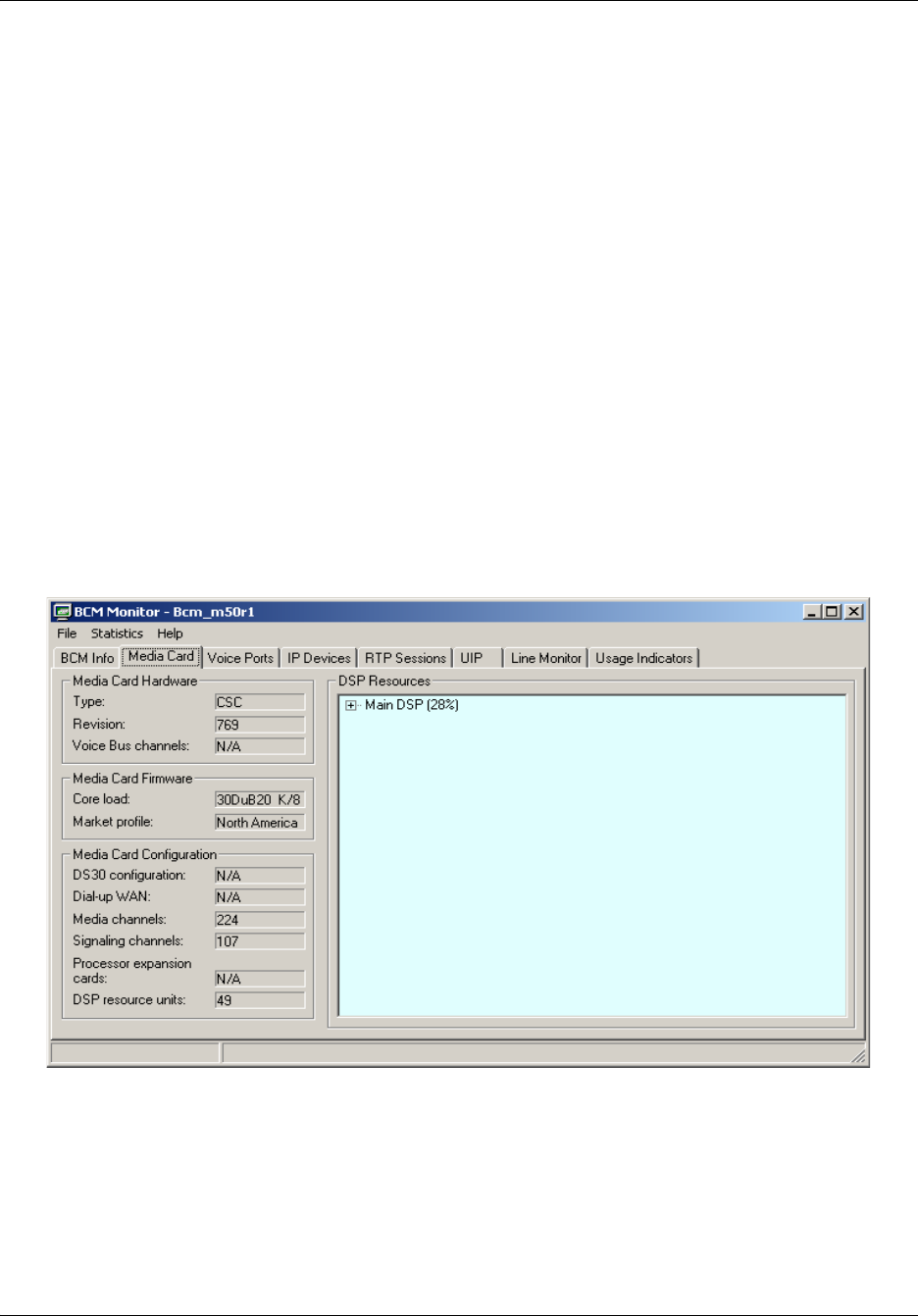
200 Chapter 13 BCM50 Utilities
NN40020-600NN40020-600
Media Card tab
The Media Card tab provides information about the telephony system of the BCM50. This tab
provides the following information for a BCM50:
• the hardware of the BCM50 main unit on which the telephony software resides
• the telephony software component release level and market profile
• configuration information, such as media channels (64 Kbps B channels), and the total number
of logical DSP resource units
• the available tasks and tasks in service
The Media Card tab provides the following information for BCM systems:
• Media Card hardware, including type and revision, and voice bus channels
• Media Card firmware, including core load and market profile
• configuration information, such as DS30 configuration, dialup WAN, media channels (64 kbps
B channels), signaling channels (D channels), processor expansion cards, and the total number
of logical DSP resource units
• the available DSP tasks and DSP tasks in-service
Voice Ports tab
The Voice Ports tab displays real-time information about configured voice ports. A configured
voice port is a logical device used for Voice Mail, and Contact Center. Values associated with
voice ports change with the usage of the switch, and are therefore well suited for dynamic logging
to view trends relating to system activity.
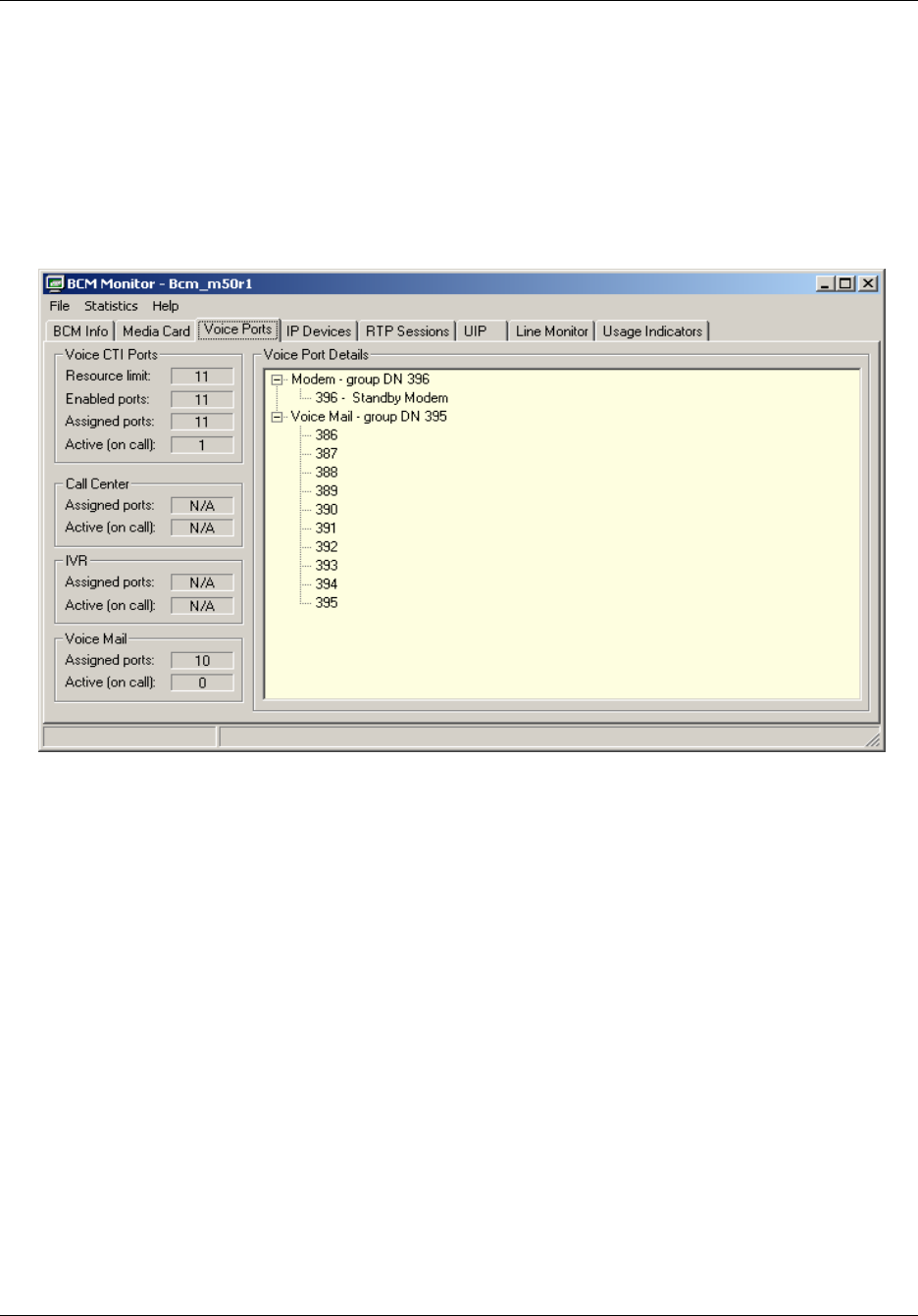
Chapter 13 BCM50 Utilities 201
BCM50 Administration Guide
You can use the Voice Ports tab to view the following information:
• information about voice ports used by the Voice CTI services, such as the resource limit and
how many voice CTI ports are enabled and assigned
• how many Voice CTI ports are assigned to Contact Center and Voice Mail
• how many assigned ports are currently active, and the DN of the user assigned to the port
• voice port details, which show information about activity on each enabled voice port
IP Devices tab
The IP Devices tab displays information about call activity associated with IP sets, wireless sets,
and IP trunks. IP sets include IP clients (for example, the i2050 softphone), i200x IP sets, and
wireless sets.
The IP Devices tab shows how many sets in each category are enabled, connected, and active. The
tab displays the DN, IP address, and type of set for each active call.
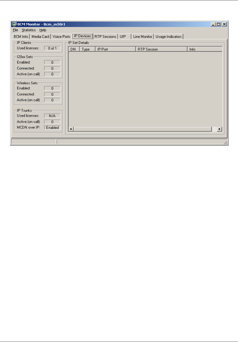
202 Chapter 13 BCM50 Utilities
NN40020-600NN40020-600
RTP Sessions tab
The RTP Sessions tab shows details about RTP (Real Time Protocol over UDP) sessions, which
involve either the BCM50 system or an IP set controlled by the BCM50 system.
You can use the information in this tab to monitor the direct path between two IP sets.
The tab displays information about:
• local IP endpoints (two sets both connected to the BCM50)
— combinations of IP to IP, TDM to IP, and TDM to TDM
— an estimate of network traffic generated by RTP sessions between TDM devices or local
IP devices
• local to remote IP endpoints
— combinations of IP to IP, TDM to IP
— an estimate of network traffic generated by RTP sessions
• remote IP endpoints (IP to IP)
— an estimate of network traffic generated by RTP sessions between remote IP endpoints
• the number of allocated Media Gateways that are providing a connection between a TDM
device and an IP endpoint
The RTP Sessions tab also displays detailed information about active RTP sessions. The RTP
Session Details area displays the following line for each active session:
{IP Endpoint A}{IP Trunk X}<stream info>{IP Trunk Y}{IP Endpoint B} Codec FPP
Details
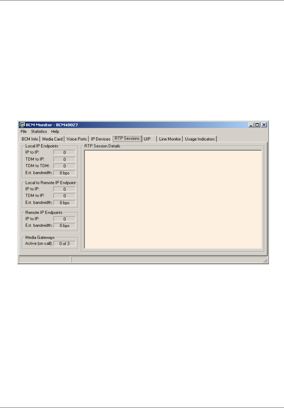
Chapter 13 BCM50 Utilities 203
BCM50 Administration Guide
The IP Endpoint tokens contain information about each IP endpoint (type, DN, IP address, RTP
port number). The IP Trunk tokens contain information about the IP Trunk used by each endpoint
(if no trunk is used, the token is omitted). The stream info token shows which RTP streams are
enabled between the two endpoints. The Codec token describes the codec type used for the RTP
session. The FPP shows the negotiated value of frames per packet. The Details token shows
additional information about the RTP session.
BCM Monitor can display real-time RTP session statistics for sessions that involve at least one
media gateway. These statistics include information about duration of the session, the number of
bytes and packets sent or received per second and per session. These statistics are useful for
troubleshooting packet loss or routing problems. For information about statistics, see “Using
statistical values” on page 209.
UIP tab
The UIP tab displays information about Universal ISDN Protocol (UIP) activity associated with IP
trunks (MCDN messages), BRI loops, and PRI loops on the BCM50.
You can monitor UIP modules by:
• enabling or disabling monitoring of MCDN over IP messages for calls made over IP trunks
• selecting and configuring a bus used by expansion modules
• selecting the type of ISDN module connected to the expansion unit
• enabling or disabling monitoring of loops on BRI modules connected to the expansion unit

204 Chapter 13 BCM50 Utilities
NN40020-600NN40020-600
Enabling UIP message monitoring
1Click the UIP tab.
2To enable or disable monitoring of MCDN over IP messages for calls made over IP trunks,
select or clear the MCDN over IP check box.
3To select an expansion module, select one of the following from the Bus selection field:
•Bus 3
•Bus 5
•Bus 7
4Select the type of ISDN module or modules:
• PRI — enables monitoring of a DTI module
• BRI — enables monitoring of BRI loops
For example, you can monitor UIP messages for loops 1 and 2 of a BRI module connected to Bus
5 and a PRI module connected to Bus 6. To do this, you would:
• Select Bus 5 - BRI, then select Module 1 - Loop 1
• SelectBus 5 - BRI, then select Module 1 - Loop 2
• Select Bus 7 - PRI
To disable monitoring of UIP messages
1Click the UIP tab.
2From the Bus drop-down list, select the bus you want to disable.
3Select the Off radio button..
To log UIP data
1Click the UIP tab.
2Select the Log UIP Data check box.
Caution: Monitoring UIP messages may affect the performance of the BCM50
system or connected peripherals. For example, if IP sets or voice ports make or
receive a high number of calls over PRI trunks, monitoring UIP increases the
amount of signalling data and may increase the response time for IP sets or voice
ports. Therefore, it is strongly recommended that you monitor only a single UIP
module at a time and restrict the monitoring time.
Note: To disable monitoring of UIP messages for MCDN over IP, you must
deselet the MCDN over IP check box.
Chapter 13 BCM50 Utilities 205
BCM50 Administration Guide
You can log UIP data to track the most recent 20 UIP messages. If you enable UIP logging, BCM
Monitor writes UIP messages in log files, which are created in the log folder in the BCM Monitor
startup directory. One log file is generated for each monitored system and each module or loop.
Log files are named IPAddr_MCDN.log, IPAddr_PRI_BusX.log, and
IPAddr_BRI_BusXModuleYLoopZ.log.
To view UIP log files
1Locate the log file that is saved to the BCM Monitor startup directory.
2Open the log file with a text editor, such as Notepad, or a spreadsheet application, such as
Microsoft Excel.
You can view the amount of time after which monitoring of selected UIP modules will be
disabled, and you can disable the monitoring timeout. If you are investigating intermittent
problems, an extended monitoring period may be required. In this case, disable the monitoring
timeout and enable logging of UIP data.
To configure timeout settings
1Click the UIP tab.
2To disable the timeout, select the Disable Timeout check box.
Viewing UIP message details
The Universal ISDN Protocol Messages section displays a folder for each UIP module that is
enabled for monitoring. Each folder displays up to 20 most recent UIP messages. You can expand
UIP messages that contain at least one information element. An information element can contain
data, which you can expand as well.
Each UIP message line contains the following information:
• the direction in relation to the BCM50 (> for incoming or < for outgoing)
• the message type (CC for Call Control, MTC for Maintenance)
• the direction in relation to the call reference origin (> Cref Origin for incoming or < CRef
Origin for outgoing)
• the message name (or a hexadecimal value if the name is unknown)
• additional data extracted from information elements
Caution: Before you disable the monitoring timeout, consider the potential
impact on system performance if the BCM50 system handles a high number of
PRI calls.
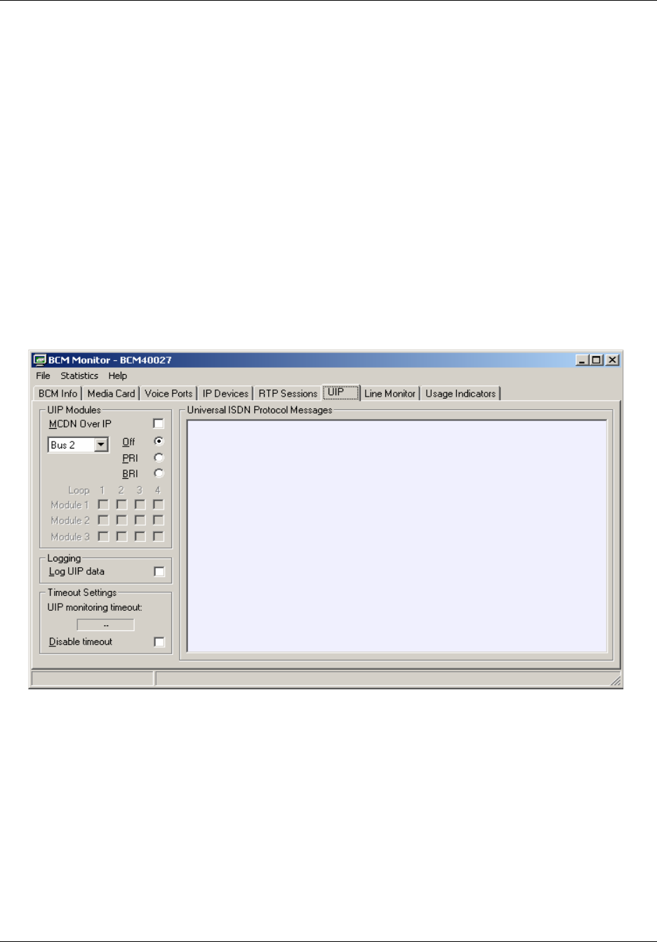
206 Chapter 13 BCM50 Utilities
NN40020-600NN40020-600
To expand a UIP message
1Click the UIP tab.
The Universal ISDN Protocol Messages area displays detailed information about monitored
UIP modules.
2In the Universal ISDN Protocol Messages area, double-click a UIP message.
Information elements appear below the UIP message.
To clear UIP message details
1Click the UIP tab.
The Universal ISDN Protocol Messages area displays detailed information about monitored
UIP modules.
2In the Universal ISDN Protocol Messages area, right-click a UIP message or information
element and select Clear Tree.
The entire tree is cleared from the Universal ISDN Protocol Messages area.
Line Monitor tab
The Line Monitor tab shows the status of lines on the BCM50 system. You can view the number of
active lines, and view all lines on the BCM50 system, including inactive lines.
For all lines displayed in the line monitor area, you can view the following information:
• number and name — displays the line number and line name
• duration — displays the duration of the call
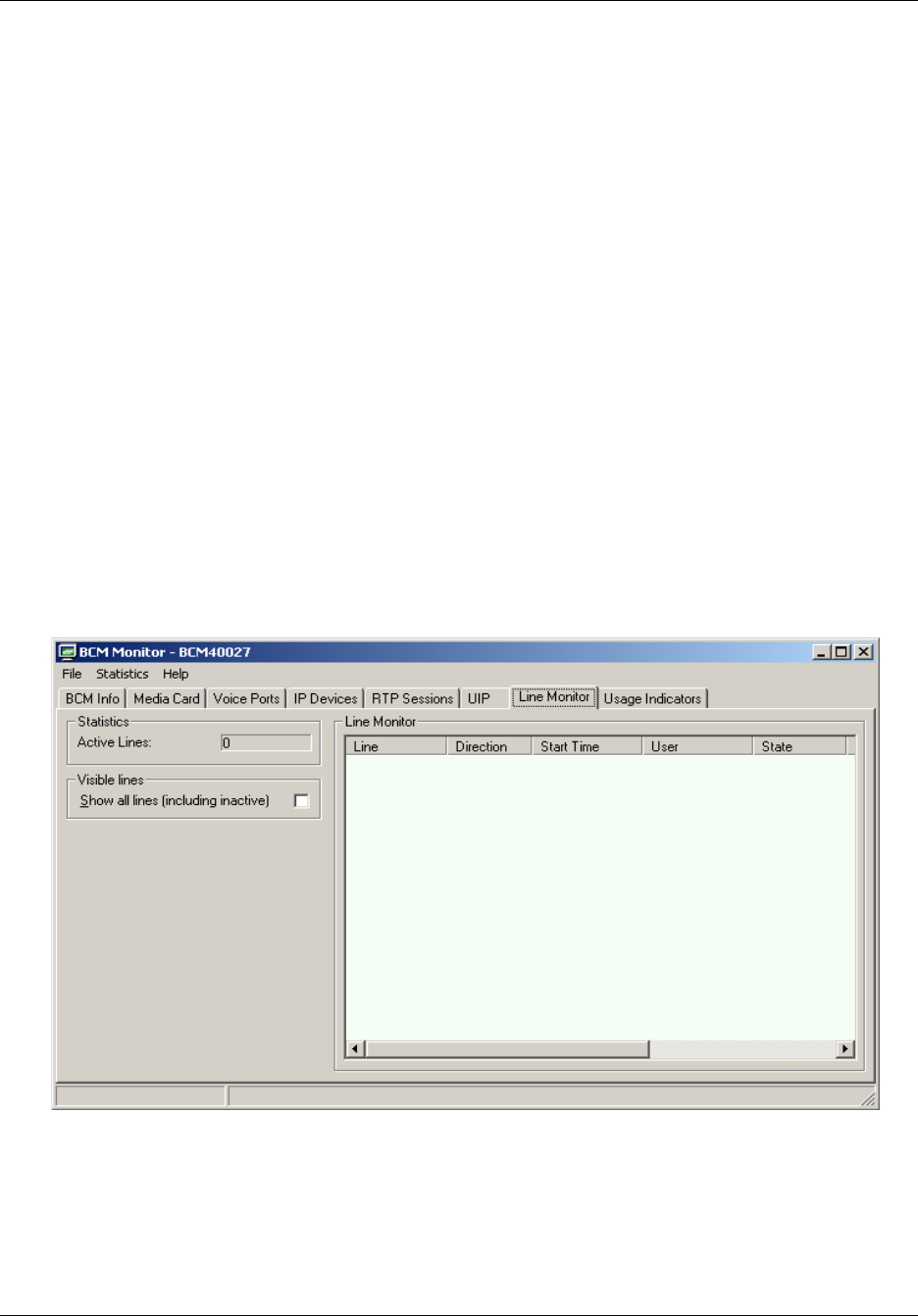
Chapter 13 BCM50 Utilities 207
BCM50 Administration Guide
• direction — “Outgoing” indicates that the call originated from the BCM50; “Incoming”
indicates that the call originated from outside and is directed at the BCM50
• start time — displays the time and date on which the call started
• user — displays the DN and name of the BCM50 user
• state — displays Idle if there is no active call on the line; displays Dialing if the BCM50 user
is in the process of dialing digits to place a call; dispalys Alerting if a call has been received on
the line and a BCM50 user’s phone is ringing; displays Connected if the line has a connected
call; displays Held if the line has a call on hold.
In the line monitor area, colours are used to indicate the state of each line:
• gray represents lines that are idle
• blue represents lines that are active
• red represents lines that are alerting
• dark red represents lines that are on hold
To view all lines
1Click the Line Monitor tab.
2Click the Show All Lines (Including Inactive) check box.
The Line Monitor area displays all lines on the BCM50 system. For lines displayed in light
gray, previous calls are shown until a new call is placed or received on that line.
Usage Indicators tab
The Usage Indicators tab displays real time information about the BCM50 system.

208 Chapter 13 BCM50 Utilities
NN40020-600NN40020-600
The tab displays the following information:
• BCM50 system data, including CPU and memory use
• resources used on the Media Card, including signaling channels, media channels, voice bus
channels, and DSP resources
• active telephony devices, such as IP trunks, IP sets. voice ports, and media gateways
The information is displayed as an absolute figure and as a percentage of the resource used. You
can capture a static snapshot of this information or log it dynamically. For more information about
snapshots, see “Using BCM Monitor to analyze system status” on page 194.
Usage values
Usage values are accompanied by a colored bar. Table 65 describes the usage value indicators and
recommended actions.
Note: The Usage Indicators tab may show high CPU usage occuring on the
BMC50. When you create backup archives or log archives, a high level of CPU
usage may occur. This level of CPU usage is normal during backup and log
management operations.
Table 65 Usage indicators
Indicator color Indicator meaning Recommended action
Green Usage values are normal. None.
Yellow Potential resource problem. Further investigation is recommended if an
indicator remains yellow for an extended
period.
Red Critical resource problem. Further investigation is recommended if an
indicator remains red for more than a few
seconds.
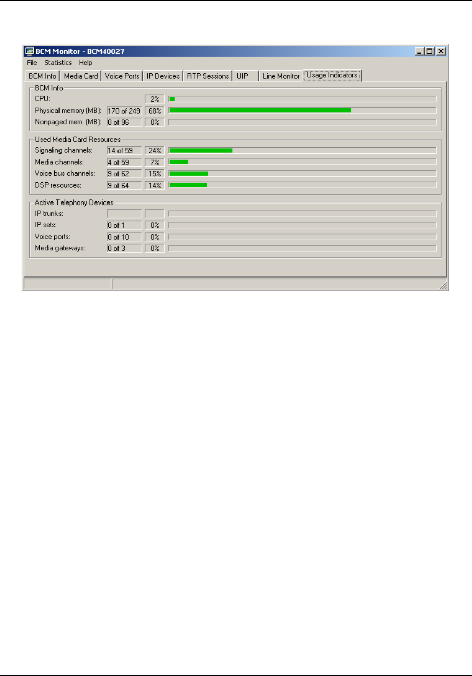
Chapter 13 BCM50 Utilities 209
BCM50 Administration Guide
Using statistical values
BCM Monitor stores the minimum and maximum values for many of the statistics that appear on
BCM Monitor tabs. A statistic must be a numeric value and must change over time; that is, the
value cannot be a static value. Examples of statistics that have minimum and maximum values are
CPU usage, Active Lines, and Enabled i20XX sets. Examples of statistics that do not have
minimum and maximum values are Dial-up WAN (which is not a numeric value) and Serial
Number (which is static).
The values that BCM Monitor displays are the minimum and maximum values for the current
BCM Monitor session. The minimum and maximum values are reset when you exit the BCM
Monitor.
You can do the following with statistical values:
• view minimum and maximum values
• view the date and time of minimum and maximum values
• reset minimum and maximum values
Viewing minimum and maximum values
Click the value on the BCM Monitor panel for which you want to view the minimum or maximum
value.
The current (Cur:), minimum (Min:), and maximum (Max:) values appear on the Status bar at the
bottom of the panel.
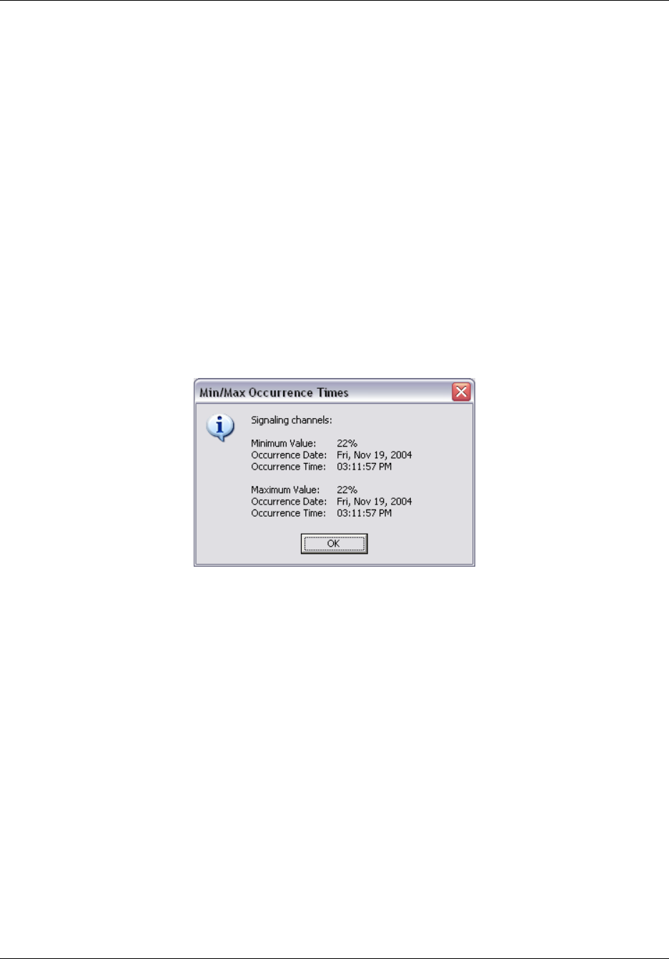
210 Chapter 13 BCM50 Utilities
NN40020-600NN40020-600
The three values remain on the Status bar until you select another value. These values also
continue to change as the value for the selected statistic changes. This is useful if you want to
monitor a single statistic on one panel while you are viewing the information on another panel.
Viewing the date and time of minimum and maximum values
When BCM Monitor stores the minimum and maximum value, it also stores the date and time
when the minimum or maximum occur.
To view the date and time of minimum and maximum values
1Select the value for which you want to view the minimum or maximum value.
2From the Statistics menu, select Show Min/Max Times.
A dialog box appears with the date and time when the minimum and maximum values
occurred.
3Click the OK button to close the dialog box.
Resetting minimum and maximum values
When you reset the minimum and maximum values, the current minimum and maximum values
are deleted and BCM Monitor starts recording new values.
To reset the minimum and maximum values for a statistic
1Click the value you want to reset.
2Do one of the following:
aOn the Statistics menu, click Reset Current Min/Max.
bTo reset the minimum and maximum values for all statistics, select Reset All Min/Max.
from the Statistics menu.
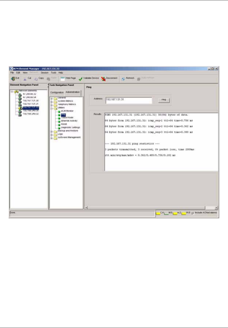
Chapter 13 BCM50 Utilities 211
BCM50 Administration Guide
Ping
Ping (Packet InterNet Groper) is a utility that you can use to verify that a route exists between the
BCM50 and another device. Ping sends an ICMP (Internet Control Message Protocol) echo
request message to a host. It expects an ICMP echo reply, which you can use to measure the
round-trip time to the selected host. You can measure the percent packet loss for a route by
sending repeated ICMP echo request messages.
Figure 36 Ping utility
To ping a device
1Click the Administration tab.
2Open the Utilities folder, and then click Ping.
The Ping panel opens.
3In the Address field, enter the IP address of the element you want to ping.
4Click the Ping button.
The results appear in the Results area.

212 Chapter 13 BCM50 Utilities
NN40020-600NN40020-600
Trace Route
You can use Trace Route to measure round-trip times to all hops along a route. This helps you to
identify bottlenecks in the network. Trace Route uses the IP TTL (time-to-live) field to determine
router hops to a specific IP address. A router must not forward an IP packet with a TTL field of 0
or 1. Instead, a router discards the packet and returns to the originating IP address an ICMP time
exceeded message.
Traceroute sends an IP datagram with a TTL of 1 to the selected destination host. The first router
to handle the datagram sends back a time exceeded message. This message identifies the first
router on the route. Trace Route then transmits a datagram with a TTL of 2.
The second router on the route returns a time exceeded message until all hops are identified. The
Traceroute IP datagram has a UDP Port number not likely to be in use at the destination (normally
greater than 30,000). The destination returns a port unreachable ICMP packet. The destination host
is identified.
To perform a trace route
1Click the Administration tab.
2Open the Utilities folder, and then click Trace Route.
The Trace Route panel opens.
3In the Maximum Number of Hops field, enter the maximum number of hops on the route.
The default is 5 hops.
4In the Address field, enter the IP address of the element for which you want to perform a trace
route.
5Click the Trace Route button.
The results are displayed in the Results area.
Ethernet Activity
The Ethernet Activity panel is a utility that you can use to view ethernet activity in the BCM50
system.
Note: Establishing a PPP link over a modem make take some time. If the Ping
utility times out before the modem call can be established, click the Ping button
again.

Chapter 13 BCM50 Utilities 213
BCM50 Administration Guide
To view Ethernet activity
1Click the Administration tab.
2Open the Utilities folder, and then click Ethernet Activity.
The Ethernet Activity panel opens.
3In the Ethernet Activity area, click the Retrieve button.
Details are displayed in the Results area.
Reset
You can use the Reset utility to:
• reboot the BCM50 system
• perform a warm reset of telephony services
• perform a cold reset of telephony services
• perform a cold reset of the router
Table 66 lists the Reset functions.
Table 66 Reset functions
Function Description Impact
Reboot BCM50 System Restarts the operating system of the
BCM50 system
Temporarily stops all services on the
system. Restarts all services.
This operation does not affect
configuration parameters or
programming.
Warm Reset Telephony
Services
Restarts telephony services running
on the BCM50 system
Restarts all telephony services,
including LAN CTE, Voicemail, and
IP telephony.
This operation does not affect
configuration parameters or
programming.
Cold Reset Telephony
Services
Resets telephony programming of
the BCM50 system to the factory
defaults for that software level
Affects all telephony services,
including LAN CTE, Voicemail, and
IP telephony.
Telephony services restart with all
telephony programming at default
values for the specified region,
template, and start DN, for the
current software release level.
A cold reset erases voice message
mailboxes and messages if the DN
length is not set to system defaults.
For information about setting the DN
length, refer to the BCM50 Device
Configuration Guide.
Cold Reset Router Resets the router programming to
the factory defaults.
Affects services that rely on the
WAN.
214 Chapter 13 BCM50 Utilities
NN40020-600NN40020-600
Rebooting the BCM50 system
To reboot the BCM50
1Click the Administration tab.
2Open the Utilities folder, and then click Reset.
The Reset panel opens.
3Click the Reboot BCM50 System button.
A confirmation dialog box opens.
4Click the OK button.
The operating system of the BCM50 restarts.
Performing a warm reset of BCM50 telephony services
To perform a warm reset of BCM50 telephony services
1Click the Administration tab.
2Open the Utilities folder, and then click Reset.
The Reset panel opens.
3Click the Warm Reset Telephony Services button.
A confirmation dialog box opens.
4Click the OK button.
All telephony services are restarted, including LAN CTE, Voicemail, and IP telephony.
Caution: Rebooting the BCM50 system temporarily stops all services running
on the system.
Caution: All active calls on the BCM50 system will be dropped.

Chapter 13 BCM50 Utilities 215
BCM50 Administration Guide
Performing a cold reset of BCM50 telephony services
To perform a cold reset of BCM50 telephony services
1Click the Administration tab.
2Open the Utilities folder, and then click Reset.
The Reset panel opens.
3Click the Cold Reset Telephony Services button.
The Cold Reset Telephony dialog box displays.
4Configure the Cold Reset Telephony attributes.
5Click the OK button.
All telephony services are reset, including LAN CTE, Voicemail, and IP telephony.
Diagnostic settings
Diagnostic settings is a utility that allows you to determine the level of system reporting you
require for released ISDN or VoIP calls. You can choose to have no text, a simple explanation, or
a detailed explanation.
This section provides the procedures “To set Release Reasons”.
To set Release Reasons
To set Release reasons, follow these steps:
1Click Administration, Utilities, Diagnostic settings.
2Click the Telep hony tab.
The Release Reasons panel appears. See Figure 37.
Caution: Performing a cold reset of telephony services erases all telephony
programming, as well as all Voice Message mailboxes and messages. Telephony
services will restart with all telephony programming at default values for the
specified region, template, and start DN, for the current software release level.
Table 67 Configure Hard Reset Telephony attributes
Attribute Action
Region Specify the startup region.
Template Specify the startup template. Options are: PBX or DID.
Start DN Specify the startup DN. The default value is 221.
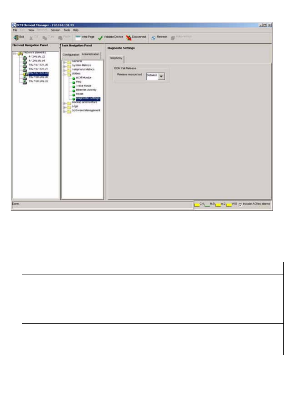
216 Chapter 13 BCM50 Utilities
NN40020-600NN40020-600
Figure 37 Telephony diagnostic settings
3From the Release Reason drop-down menu, select the level of reporting that you require.
Table 68 lists the possible values for Release reasons.
Table 68 Release reasons
Attributes Values Description
None Default Value No text will accompany a dropped call notification.
Simple Cause Code:
Off
On
Off: no text is provided
On: the code only is provided
Note: if you select Simple text, you must turn off the Cause code. This is for
diagnostic purposes only.
Detailed No setting A detailed explanation of the Cause code is provided.
Cause
Code
check box This check box appears when you select Simple in the Release Reason
Text drop-down menu. When you select the check box, only the cause code
accompanies a dropped call notification.

Chapter 14 Backing Up and Restoring BCM50 Data 217
BCM50 Administration Guide
Chapter 14
Backing Up and Restoring BCM50 Data
This chapter provides information about how to back up and restore data from the BCM50 system.
Overview of backing up and restoring data
Before you make administrative changes or as your BCM50 system accumulates information, you
can create a backup archive on the BCM itself, on a USB drive, or on another location on the
network. At a later time, you can restore the data to the BCM50.
You can restore data to the same system or to a different system at the same software release level.
The BCM50 checks the software release level of the destination system and will provide a warning
if an incompatibility prevents the backup from being restored onto the selected system.
You can also restore data to a system that you have upgraded to the next hardware release level.
For example, you can create a backup archive of a system, upgrade that system to the next
hardware release level, and then restore the programming and configuration settings. On BCM50
systems equipped with a BRI module, you will need to reconfigure the telephony resources and
trunks associated with the module after performing a restore operation.
Backup and restore operations are performed by only one operator at a time to avoid conflicts with
other operations. All passwords and database records included with your backup file are
encrypted. When you perform a restore operation, the password on the target system must match
the password that the backup archive was created with.
You can perform backup operations on demand or you can schedule a single backup or recurring
backups. You can view the backup schedule and change it as required, and you can also save a
record of the backup schedule that you set. For information about saving programming records,
see “Saving programming records” on page 59.
A restore operation can be performed on demand only.
Backup and restore options
You can backup and restore the settings and service data of your BCM50.
Note: Nortel recommends that you back up BCM50 data on a regular basis. In
particular, you should perform a backup of the BCM50 and router data before you
undertake major configuration changes and before you apply a software update or
upgrade.

218 Chapter 14 Backing Up and Restoring BCM50 Data
NN40020-600NN40020-600
During the backup procedure, you can exclude a number of optional services from the backup
operation to ensure that service is not interrupted. The remainder of the services and settings are
automatically included during a backup operation. Table 69 lists the components that you can
choose to include or exclude from the backup operation.
Select the optional components that best fit your backup strategy. For example, if you do not want
to backup personal voicemail messages, you can select the CallPilot Configuration component and
deselect the CallPilot Messages component, which saves all CallPilot information except for
personal voicemail messages.
When you perform a restore operation, you can choose to restore any optional components that
were included in the backup operation.
Viewing backup and restore activity
A log archive tracks all backup and restore activities that occur on the system. You can retrieve
and view this file in the Operational logs category. The archive name is <archiver.systemlog>.
For information about logs, see Chapter 15, “Managing BCM50 Logs,” on page 245.
About backups
A backup collects the configuration settings and the data generated during the normal operation of
the BCM system.
Examples of configuration settings include:
• IP configuration details
• telephony programming
• SNMP settings
• Call Detail Recording settings
• BCM50 schedules (for example, the backup schedule, and the log retrieval schedule)
• greetings
•prompts
Examples of data generated during normal operations include:
• voicemail messages
• Call Detail Records
• faxes
Table 69 Optional components
Component Description
CallPilot Configuration Includes Voicemail and ContactCenter configuration information.
CallPilot Messages Includes Voicemail and ContactCenter configuration, Voicemail and
ContactCentre messages.
Chapter 14 Backing Up and Restoring BCM50 Data 219
BCM50 Administration Guide
• email text-to-speech
• envelope information
The BCM50 can accommodate a backup archive that is greater than 500 MB. To minimize the size
of the backup archive, exclude the optional components from the backup operation. The BCM50
will compress sections of the backup archive when it is effective to do so.
BCM50 backup file
When you perform a backup operation, the BCM50 creates a backup archive and stores it in a
location that you specify. The archive file includes embedded archives, each of which represent a
different part of the BCM50 system:
• archive.sig — ensures the integrity of all the data in the archive
• various archive files — various archive files that contain the configuration settings and
operating data
In addition to the configuration and application information, every backup operation includes the
following files:
• Software Inventory — provides a snapshot of the software component release level
• Software History — provides a snapshot of the software history
These files document the system software level from which the backup was taken. They are
located in the archive softwarelevel.tar.gz.
Backup archives transferred to servers or to attached USB storage devices are named according to
the system name of the BCM50, the date, and the time of the backup. Archives are prefixed with
Bak_. For example, an archive created on July 8, 2005 at 1:52:55 pm is named
Bak_acme-melbourne_20050708T135255.tar.
Caution: A backup operation can interrupt services running on the BCM50. A
warning displays whenever the backup will cause a service interruption. If you
want to perform a backup that does not affect the system, you can exclude
services that would be affected. Alternatively, you can include these services and
perform a backup at a time when the system is typically not in use.
Caution: The backup operation takes longer on a system with many saved voice
messages. As a result, the backup archive can be quite large and can take 30
minutes or more to reach a remote server, depending on your network speed.
Note: To manage your Voicemail options, you must use the CallPilot Manager
and not the Element Manager.
Note: When you create a backup archive, a high level of CPU usage may occur.
This level of CPU is normal during a backup operation.

220 Chapter 14 Backing Up and Restoring BCM50 Data
NN40020-600NN40020-600
For USB storage devices, an additional copy of the backup archive is stored in the file backup.tar;
the BCM will reference this file during a USB restore operation. Only the most recent backup to
the USB storage device is available for a restore operation. To access historical backup archives,
attach the USB storage device to a personal computer and use the Restore from My Computer
option.
Backup destinations
Table 70 lists the destinations to which you can back up configuration and application data.
Whichever destination you choose, the backup operation replaces the BCM’s own copy of the
archive, so that a copy of the most recent backup always remains on the BCM50. You can use this
to restore your BCM50 without transferring a backup from an external device or server.
Table 70 Backup destinations
Destination Description
BCM50 For an immediate backup, saves backup archives to the hard drive of the
BCM50.
You cannot specify a path. Each backup rewrites any pre-existing backup
of the same type.
My Computer For an immediate backup, saves backup archives to any accessible
location on the client PC on which the BCM50 Element Manager is
installed. You can specify a name for the backup, so that the pre-existing
backup is not automatically overwritten.
Network Folder Saves data to a shared network folder.
The remote server must provide a Microsoft Windows-like shared file
resource and a user account with rights to create and write files in the
destination location. You cannot browse the network directories to select
the destination folder, but you can specify a directory by identifying the
path.
USB Storage Device Saves backup archives to a USB storage device.
The files will be written to the top directory level. You cannot specify a path
to a different directory on the storage device. Each backup overwrites any
pre-existing backup of the same type.
A USB storage device must be formatted as FAT32.
FTP Server Saves backup archives to a File Transfer Protocol server.
Credentials and backup data are sent without encryption. The remote
server must provide an FTP server application and a user account with
rights to allow the BCM50 to create and write files in the destination
location.
You cannot browse the FTP server to select the destination folder, but you
can specify a directory by identifying the path.
SFTP Server Saves backup archives to an SFTP server. This method encrypts the login
credentials and the data in transit.
You must set up the remote SFTP server to allow the BCM50 to
communicate with the SFTP server. When you set up an SFTP folder as a
storage location on the network, you must use an SCP server. BCM50
supports OpenSSH 3.7.

Chapter 14 Backing Up and Restoring BCM50 Data 221
BCM50 Administration Guide
For more information about how to access and use the storage locations, see “BCM50 common
file input/output processes” on page 68.
Before you back up BCM50 data, make sure that the BCM50 has appropriate access to the shared
resource on which you will store the data. You must set full access permissions on the shared
resource.
Performing immediate backups
You can perform immediate backups to the following storage locations:
• BCM50
• client PC
• network folder
• USB storage device
•FTP server
• SFTP (SCP) server
Performing an immediate backup to the BCM50
To perform an immediate backup to the BCM50
1In the task panel, click the Administration tab.
2Open the Backup and Restore folder, and then click Backup.
The Backup panel opens and displays the Immediate Backup tab. In the Backup To
selection field, choose BCM.
3Click the Backup button.
The Backup window opens.
4In the Optional Components table, select or clear the check box for each component to
include or exclude these components from the backup operation.
5Click the OK button.
A warning window opens. Read the warning carefully before proceeding.
6Click the Ye s button to proceed.
A progress window opens. When the backup is complete, the Backup Complete message
appears.
7Click the OK button.
Caution: A backup operation can interrupt services running on the BCM50. A
warning displays whenever the backup will cause a service interruption. If you
want to perform a backup that does not affect the system, you can exclude
services that would be affected. Alternatively, you can include these services and
perform a backup at a time when the system is typically not in use.

222 Chapter 14 Backing Up and Restoring BCM50 Data
NN40020-600NN40020-600
Performing an immediate backup to your personal computer
To perform an immediate backup to your personal computer
1In the task panel, click the Administration tab.
2Open the Backup and Restore folder, and then click Backup.
The Backup panel opens and displays the Immediate Backup tab.
3In the Backup To selection field, select My Computer.
4Click the Backup button.
The Backup window opens.
5In the Optional Components table, select or clear the check box for each component to
include or exclude these components from the backup operation.
6Click the OK button.
A warning message appears. Read the warning carefully before proceeding.
7Click the Ye s button to proceed.
A progress window opens. When the backup preparation is complete, the Save window opens.
8Specify the directory and enter a file name in the File Name field. Enter a file name with a .tar
extension (e.g. backup2.tar) so that you can examine the file with a utility such as WinZip. If
you do not select the folder backup, the new backup file will be stored in the root of this
folder.
9Click the Save button.
When the backup is complete the Backup Complete message appears.
10 Click the OK button.
Caution: A backup operation can interrupt services running on the BCM50. A
warning displays whenever the backup will cause a service interruption. If you
want to perform a backup that does not affect the system, you can exclude
services that would be affected. Alternatively, you can include these services and
perform a backup at a time when the system is typically not in use.

Chapter 14 Backing Up and Restoring BCM50 Data 223
BCM50 Administration Guide
Performing an immediate backup to a network folder
To perform an immediate backup to a network folder
1In the task panel, click the Administration tab.
2Open the Backup and Restore folder, and then click Backup.
The Backup panel opens and displays the Immediate Backup tab.
3In the Backup To selection field, select Network Folder.
4Configure the Network Folder attributes.
5Click the Backup button.
The Backup window opens
6In the Optional Components table, select or clear the check box for each component to
include or exclude these components from the backup operation.
7Click the OK button.
A warning window opens. Read the warning carefully before proceeding.
8Click the Ye s button to proceed.
A progress window opens. When the backup preparation is complete, the Backup Complete
message displays.
9Click the OK button.
Caution: A backup operation can interrupt services running on the BCM50. A
warning displays whenever the backup will cause a service interruption. If you
want to perform a backup that does not affect the system, you can exclude
services that would be affected. Alternatively, you can include these services and
perform a backup at a time when the system is typically not in use.
Table 71 Configure Network Folder attributes
Attribute Action
Network Folder Enter the hostname or IP address of the network folder and the resource
name. For example, enter \\<server>\<resource>.
User Name Enter the user name associated with the network folder.
Password Enter the password of the user.
Directory Enter the path to the subdirectory (optional).

224 Chapter 14 Backing Up and Restoring BCM50 Data
NN40020-600NN40020-600
Performing an immediate backup to a USB storage device
To perform an immediate backup to a USB storage device
1In the task panel, click the Administration tab.
2Open the Backup and Restore folder, and then click Backup.
The Backup panel opens and displays the Immediate Backup tab.
3In the Backup To selection field, select USB Storage Device.
4Click the Backup button.
The Backup window opens.
5In the Optional Components table, select or clear the check box for each component to
include or exclude these components from the backup operation.
6Click the OK button.
A warning window opens. Read the warning carefully before proceeding.
7Click the Ye s button to proceed.
A progress window opens. When the backup is complete, the Backup Complete message
displays.
8Click the OK button.
Performing an immediate backup to an FTP server
To perform an immediate backup to an FTP server
1In the task panel, click the Administration tab.
2Open the Backup and Restore folder, and then click Backup.
The Backup panel opens and displays the Immediate Backup tab.
3In the Backup To selection field, select FTP Server.
Caution: A backup operation can interrupt services running on the BCM50. A
warning displays whenever the backup will cause a service interruption. If you
want to perform a backup that does not affect the system, you can exclude
services that would be affected. Alternatively, you can include these services and
perform a backup at a time when the system is typically not in use.

Chapter 14 Backing Up and Restoring BCM50 Data 225
BCM50 Administration Guide
4Configure the FTP Server attributes.
5Click the Backup button.
The Backup window opens.
6In the Optional Components table, select or clear the check box for each component to
include or exclude these components from the backup operation.
7Click the OK button.
A warning window opens. Read the warning carefully before proceeding.
8Click the Ye s button to proceed.
A progress window opens. When the backup preparation is complete, the Backup Complete
message displays.
9Click the OK button.
Performing an immediate backup to an SFTP server
To perform an immediate backup to an SFTP server
1In the task panel, click the Administration tab.
2Open the Backup and Restore folder, and then click Backup.
The Backup panel opens and displays the Immediate Backup tab.
3In the Backup To selection field, select SFTP Server.
Table 72 Configure FTP Server attributes
Attribute Action
FTP Server Enter the hostname or IP address of the FTP server.
User Name Enter the user name associated with the FTP server.
Password Enter the password associated with the FTP server.
Directory Enter the path to the subdirectory (optional).
Caution: A backup operation can interrupt services running on the BCM50. A
warning displays whenever the backup will cause a service interruption. If you
want to perform a backup that does not affect the system, you can exclude
services that would be affected. Alternatively, you can include these services and
perform a backup at a time when the system is typically not in use.

226 Chapter 14 Backing Up and Restoring BCM50 Data
NN40020-600NN40020-600
4Configure the SFTP Server attributes.
5Click the Backup button.
The Backup window opens.
6In the Optional Components table, select or clear the check box to include or exclude these
components from the backup operation.
7Click the OK button.
A warning window opens. Read the warning carefully before proceeding.
8Click the Ye s button to proceed.
A progress window opens. When the backup preparation is complete, the Backup Complete
message displays.
9Click the OK button.
Viewing and performing scheduled backups
You can create scheduled backups in order to perform backups at a date and time that you choose.
For example, you can choose a date and time during which your business is closed. This will avoid
disrupting the normal work-day routine and may allow your backup file to transfer more quickly.
You can create a schedule for a single backup operation or for backup operations that recur on a
regular basis. You can view existing scheduled backups, as well as modify and delete them.
Table 73 Configure SFTP Server attributes
Attribute Action
SFTP Server Enter the hostname or IP address of the SFTP server. For SFTP storage
locations, you must use an SCP server. BCM50 supports OpenSSH 3.7.
User Name Enter the user name associated with the SFTP server.
Password Enter the password of the user associated with the SFTP server.
Directory Enter the path to the subdirectory, as applicable.
Caution: A backup operation can interrupt services running on the BCM50. A
warning displays whenever the backup will cause a service interruption. If you
want to perform a backup that does not affect the system, you can exclude
services that would be affected. Alternatively, you can include these services and
perform a backup at a time when the system is typically not in use.

Chapter 14 Backing Up and Restoring BCM50 Data 227
BCM50 Administration Guide
Table 74 lists the information that is displayed in the Scheduled Backups table.
You can change the order of the information in the table by clicking a column heading and
dragging it to a new location in the table. You can list the information in a column in ascending or
descending order by clicking a column heading.
To view scheduled backups
1In the task panel, click the Administration tab.
2Open the Backup and Restore folder, and then click Backup.
The Backup panel opens and displays the Immediate Backup tab.
3Click the Scheduled Backups tab.
The Scheduled Backups panel opens. Any existing scheduled backups are displayed in the
Scheduled Backups table.
Performing a scheduled backup to the BCM50
To perform a scheduled backup to the BCM50
1In the task panel, click the Administration tab.
2Open the Backup and Restore folder, and then click Backup.
The Backup panel opens and displays the Immediate Backup tab.
3Click the Scheduled Backups tab.
The Scheduled Backups panel opens.
4Click the Add button.
The Add Scheduled Backup window opens. In the Backup To selection field, choose BCM.
Table 74 Information displayed in the Scheduled Backups table
Column Description
Memo Displays the memo for the scheduled backup.
Destination Displays the storage location for the backup file. For example, the FTP
server.
Schedule Displays the date and time at which the backup will be performed.
Caution: A backup operation can interrupt services running on the BCM50. A
warning displays whenever the backup will cause a service interruption. If you
want to perform a backup that does not affect the system, you can exclude
services that would be affected. Alternatively, you can include these services and
perform a backup at a time when the system is typically not in use.

228 Chapter 14 Backing Up and Restoring BCM50 Data
NN40020-600NN40020-600
5Click the OK button.
The Add Scheduled Backup window opens. Read the warning carefully before proceeding.
6In the Optional Components table, select or clear the check box to include or exclude these
components from the backup operation. Click the OK button.
7Configure the schedule attributes.
8Click the OK button.
The scheduled backup is displayed in the Scheduled Backups table.
Performing a scheduled backup to a network folder
To perform a scheduled backup to a network folder
1In the task panel, click the Administration tab.
2Open the Backup and Restore folder, and then click Backup.
The Backup panel opens and displays the Immediate Backup tab.
3Click the Scheduled Backups tab.
The Scheduled Backups panel opens.
4Click the Add button.
The Add Scheduled Backup window opens.
5In the Backup To selection field, select Network Folder.
Table 75 Configure schedule attributes
Attribute Action
Memo Enter a note for the scheduled backup, as applicable.
Recurrence Select how often the scheduled backup is to occur. Options are: Once,
Daily, Weekly, Monthly. Depending on the option you choose, the window
displays selections for the month and day of month. If you select Weekly,
days of the week are displayed. Select the check box for Daily to select the
day.
Month Select the month in which the scheduled backup is to occur.
Day of Month Select the day of the month on which the scheduled backup is to occur.
Time Select the time at which the scheduled backup is to occur.
Caution: A backup operation can interrupt services running on the BCM50. A
warning displays whenever the backup will cause a service interruption. If you
want to perform a backup that does not affect the system, you can exclude
services that would be affected. Alternatively, you can include these services and
perform a backup at a time when the system is typically not in use.

Chapter 14 Backing Up and Restoring BCM50 Data 229
BCM50 Administration Guide
6Configure the Network Folder attributes.
7Click the OK button.
The Add Scheduled Backup window opens.
8In the Optional Components table, select or clear the check box to include or exclude these
components from the backup operation.
9Configure the schedule attributes.
10 Click the OK button.
The scheduled backup is displayed in the Scheduled Backups table.
Table 76 Configure Network Folder attributes
Attribute Action
Network Folder Enter the hostname or IP address of the network folder and resource name
For example, \\<server>\<resource>.
User Name Enter the user name associated with the network folder.
Password Enter the password of the user.
Directory Enter the path to the subdirectory (optional).
Table 77 Configure schedule attributes
Attribute Action
Memo Enter a note for the scheduled backup, as applicable.
Recurrence Select how often the scheduled backup is to occur. Options are: Once,
Daily, Weekly, Monthly. Depending on the option you choose, the window
displays selections for the month and day of month. If you select Weekly,
days of the week are displayed. Select the check box for Daily to select the
day.
Month Select the month in which the scheduled backup is to occur.
Day of Month Select the day of the month on which the scheduled backup is to occur.
Time Select the time at which the scheduled backup is to occur.

230 Chapter 14 Backing Up and Restoring BCM50 Data
NN40020-600NN40020-600
Performing a scheduled backup to a USB storage device
To perform a scheduled backup to a USB storage device
1In the task panel, click the Administration tab.
2Open the Backup and Restore folder, and then click Backup.
The Backup panel opens and displays the Immediate Backup tab.
3Click the Scheduled Backups tab.
The Scheduled Backups panel opens.
4Click the Add button.
The Add Scheduled Backup window opens.
5In the Backup To selection field, select USB Storage Device.
6Click the OK button.
The Add Scheduled Backup window opens
7In the Optional Components table, select or clear the check box to include or exclude these
components from the backup operation.
8Configure the schedule attributes.
9Click the OK button.
The scheduled backup is displayed in the Scheduled Backups table.
Caution: A backup operation can interrupt services running on the BCM50. A
warning displays whenever the backup will cause a service interruption. If you
want to perform a backup that does not affect the system, you can exclude
services that would be affected. Alternatively, you can include these services and
perform a backup at a time when the system is typically not in use.
Table 78 Configure schedule attributes
Attribute Action
Memo Enter a note for the scheduled backup, as applicable.
Recurrence Select how often the scheduled backup is to occur. Options are: Once,
Daily, Weekly, Monthly. Depending on the option you choose, the window
displays selections for the month and day of month. If you select Weekly,
days of the week are displayed. Select the check box for Daily to select the
day.
Month Select the month in which the scheduled backup is to occur.
Day of Month Select the day of the month on which the scheduled backup is to occur.
Time Select the time at which the scheduled backup is to occur.

Chapter 14 Backing Up and Restoring BCM50 Data 231
BCM50 Administration Guide
Performing a scheduled backup to an FTP server
To perform a scheduled backup to an FTP server
1In the task panel, click the Administration tab.
2Open the Backup and Restore folder, and then click Backup.
The Backup panel opens and displays the Immediate Backup tab.
3Click the Scheduled Backups tab.
The Scheduled Backups panel opens.
4Click the Add button.
The Add Scheduled Backup window opens.
5In the Backup To selection field, select FTP Server.
6Configure the FTP Server attributes.
7Click the OK button.
The Add Scheduled Backup window opens.
8In the Optional Components table, select or clear the check box to include or exclude these
components from the backup operation.
9Configure the schedule attributes.
Caution: A backup operation can interrupt services running on the BCM50. A
warning displays whenever the backup will cause a service interruption. If you
want to perform a backup that does not affect the system, you can exclude
services that would be affected. Alternatively, you can include these services and
perform a backup at a time when the system is typically not in use.
Table 79 Configure FTP Server attributes
Attribute Action
FTP Server Enter the hostname or IP address of the FTP server.
User Name Enter the user name associated with the FTP server.
Directory Enter the path to the subdirectory (optional).
Table 80 Configure schedule attributes
Attribute Action
Memo Enter a note for the scheduled backup, as applicable.
Recurrence Select how often the scheduled backup is to occur. Options are: Once,
Daily, Weekly, Monthly. Depending on the option you choose, the window
displays selections for the month and day of month. If you select Weekly,
days of the week are displayed. Select the check box for Daily to select the
day.
Month Select the month in which the scheduled backup is to occur.

232 Chapter 14 Backing Up and Restoring BCM50 Data
NN40020-600NN40020-600
10 Click the OK button.
The scheduled backup is displayed in the Scheduled Backups table.
Performing a scheduled backup to an SFTP server
To perform a scheduled backup to an SFTP server
1In the task panel, click the Administration tab.
2Open the Backup and Restore folder, and then click Backup.
The Backup panel opens and displays the Immediate Backup tab.
3Click the Scheduled Backups tab.
The Scheduled Backups panel opens.
4Click the Add button.
The Add Scheduled Backup window opens.
5In the Backup To selection field, select FTP Server.
6Configure the SFTP Server attributes.
7Click the OK button.
The Add Scheduled Backup window opens.
Day of Month Select the day of the month on which the scheduled backup is to occur.
Time Select the time at which the scheduled backup is to occur.
Caution: A backup operation can interrupt services running on the BCM50. A
warning displays whenever the backup will cause a service interruption. If you
want to perform a backup that does not affect the system, you can exclude
services that would be affected. Alternatively, you can include these services and
perform a backup at a time when the system is typically not in use.
Table 81 Configure SFTP Server attributes
Attribute Action
SFTP Server Enter the hostname or IP address of the SFTP server. For SFTP storage
locations, you must use an SCP server. BCM50 supports OpenSSH 3.7.
User Name Enter the user name associated with the SFTP server.
Password Enter the password of the user associated with the SFTP server.
Directory Enter the path to the subdirectory (optional).
Table 80 Configure schedule attributes
Attribute Action

Chapter 14 Backing Up and Restoring BCM50 Data 233
BCM50 Administration Guide
8In the Optional Components table, select or clear the check box to include or exclude these
components from the backup operation.
9Configure the schedule attributes.
10 Click the OK button.
The scheduled backup is displayed in the Scheduled Backups table.
Modifying and deleting scheduled backups
You can modify existing scheduled backups. You can modify:
• the memo for the scheduled backup
• optional components to include in the backup
• schedule details for the backup
You can also delete a scheduled backup.
Modifying a scheduled backup
To modify a scheduled backup
1In the task panel, click the Administration tab.
2Open the Backup and Restore folder, and then click Backup.
The Backup panel opens and displays the Immediate Backup tab.
Table 82 Configure schedule attributes
Attribute Action
Memo Enter a note for the scheduled backup, as applicable.
Recurrence Select how often the scheduled backup is to occur. Options are: Once,
Daily, Weekly, Monthly. Depending on the option you choose, the window
displays selections for the month and day of month. If you select Weekly,
days of the week are displayed. Select the check box for Daily to select the
day.
Month Select the month in which the scheduled backup is to occur.
Day of Month Select the day of the month on which the scheduled backup is to occur.
Time Select the time at which the scheduled backup is to occur.
Caution: A backup operation can interrupt services running on the BCM50. A
warning displays whenever the backup will cause a service interruption. If you
want to perform a backup that does not affect the system, you can exclude
services that would be affected. Alternatively, you can include these services and
perform a backup at a time when the system is typically not in use.

234 Chapter 14 Backing Up and Restoring BCM50 Data
NN40020-600NN40020-600
3Click the Scheduled Backups tab.
The Scheduled Backups panel opens.
4Select a scheduled backup in the Scheduled Backups table.
5Click the Modify button.
The Modify Scheduled Backup window opens.
6Modify the attributes of the scheduled backup as required. For information about how to
configure the attributes, see the procedures in “Viewing and performing scheduled backups”
on page 226.
7Click the OK button.
The modified backup is displayed in the Scheduled Backups table.
To delete a backup schedule
1In the task panel, click the Administration tab.
2Open the Backup and Restore folder, and then click Backup.
The Backup panel opens and displays the Immediate Backup tab.
3Click the Scheduled Backups tab.
The Scheduled Backups panel opens.
4Select a scheduled backup in the Scheduled Backups table.
5Click the Delete button.
A confirmation window opens.
6Click the Ye s button.
The scheduled backup is removed from the Scheduled Backups table.
Restoring BCM50 system data
You can restore BCM50 configuration and application data using the Element Manager.
The restore software determines compatibility with the backup archive. Incompatible backups
cannot be restored at all. Compatible backups may have incompatible sub-components which will
be automatically excluded from a Restore operation. This situation can occur if your BCM50
software is upgraded and a component changes the data that it includes in the backup. New
backups should be made after any change to your BCM50 software to avoid this situation.
However, it may be possible to recover data for components that have not changed from backups
made prior to your software upgrade.
Restore operations are available on demand only; they cannot be scheduled.
You can retrieve the most recent backup file that you want to use for the restore operation from the
BCM50 or from an external storage location. Nortel recommends that you always use the same
storage location when you perform a restore operation. This practice will avoid potential
mismatches in the backup archives. For information about storage locations, see “Backup
destinations” on page 220.

Chapter 14 Backing Up and Restoring BCM50 Data 235
BCM50 Administration Guide
When you restore data, the following details are available to you:
• the size of the backup file
• the backup date
• the backup version
Restore options
You can select the components which you want to restore.
You can restore a backup to a different system; for example, to quickly bring a second system into
service in a new installation. In this case, not all of the configuration information in the
Configuration backup is relevant to the second system. You can select whether to restore
device-specific configuration information, such as network settings. You may wish to exclude
certain components from being restored. For example, the network settings are often excluded
from a restore operation to avoid giving two machines on your network the same identity.
When you restore from a backup archive, you can check the level of the software update of the
archive file, and determine which updates you will need to apply before you begin the restore
operation. The “softwarelevel.tar.gz” file within the backup archive contains up to two text files:
“installedsoftware.txt” and “history.log.” The “installedsoftware.txt” file is present at all times,
while the “history.log” file is present only if software patches were applied to the BCM50 or if a
software upgrade was performed. The “history.log” file contains the update history of the BCM50
at the time the backup archive was made. You can use this file to identify the software updates that
must be applied to the target system before you perform the restore operation.
Backup information can be restored only to another unit that has the same software release level. If
the second unit has an older software release level, you can use the Reset button on the BCM50
front panel to reset the BCM50 unit to the factory default software level and default configuration
settings. You can then apply software updates to bring the unit to the same software release level
as that of the unit from which the backup was taken.
For information about applying software updates to the BCM50, see Chapter 17, “Managing
BCM50 Software Updates,” on page 265.
The BCM50 verifies that the software release level of the unit to which the backup is being applied
is consistent with the software release level of the backup file. If a potential issue is detected, the
BCM Element Manager provides you with an error message.
Optional components
You can restore configuration or application data for the following optional components:
• NAT and filters / QoS queueing
• Data Services + Network Interfaces
•Keycodes
• Doorphone
• QoS Monitor
• Security
•SNMP

236 Chapter 14 Backing Up and Restoring BCM50 Data
NN40020-600NN40020-600
• Date and Time
• Call Data Recording
• IP Telephony
• Scheduling
• LAN CTE
• Survivable Remote Gateway
•IP Music
• CallPilot Messages
• CallPilot Configuration
• Media Services Manager
• Core Telephony
Effects on the system
A restore operation is a service-affecting operation. A number of services running on the BCM50
system are stopped and then restarted after the data has been restored. A reboot warning is
displayed if any of the components selected for restoration require a system restart. Table 83 lists
the effects of restoring optional components.
Restore operations and logs
A log file tracks all backup and restore activities that occur on the system. You can retrieve and
view this file in the Operational Logs category. The file name is <archiver.systemlog>.
For information about BCM50 logs, see Chapter 15, “Managing BCM50 Logs,” on page 245.
Note: To restore SIP Trunk Account settings, you must select the Security
component when you perform a restore operation.
Table 83 Effects of a restore operation on the system
Component Effect
Core Telephony Service interruption.
IP Telephony Service interruption.
Keycodes Reboots the device.
Data Services + Network
interfaces
Network interruption.
NAT and filters/QoS Queueing Temporarily disables NAT, IP Policy, and VoIP.
Security Reboots the device.
CallPilot Messages Service interruption. Existing voice messages will be lost.
CallPilot Configuration Service interruption. Existing voice messages will be lost.
Media Services Manager Service interruption.

Chapter 14 Backing Up and Restoring BCM50 Data 237
BCM50 Administration Guide
Restoring data from the BCM50
To restore data from the BCM50
1In the task panel, click the Administration tab.
2Open the Backup and Restore folder, and then click Restore.
The Restore panel opens. The Restore From selection field has BCM as a default value.
3Click the Restore button.
The Select Components to Restore window opens.
4Select the optional components that you want to include from the backup file.
5Click the OK button.
A warning window opens and displays information about components that will be affected by
the restore operation. Read the warning carefully before proceeding.
6Click the Ye s button to proceed.
A progress window opens. When the operation is complete, the Restore Complete window
opens.
7Click the OK button.
Restoring data from your personal computer
To restore data from your personal computer
1In the task panel, click the Administration tab.
2Open the Backup and Restore folder, and then click Restore.
The Restore panel opens.
3In the Restore From selection field, select My Computer.
4Click the Restore button.
The Open window opens.
Caution: A backup operation can interrupt services running on the BCM50. A
warning displays whenever the backup will cause a service interruption. If you
want to perform a backup that does not affect the system, you can exclude
services that would be affected. Alternatively, you can include these services and
perform a backup at a time when the system is typically not in use.
Caution: A restore operation can interrupt services running on the BCM50. A
warning displays whenever restoring data will cause a service interruption. If you
want to perform a restore operation that does not affect the system, you can
exclude services that would be affected. Alternatively, you can include these
services and perform a restore operation at a time when the system is typically not
in use.

238 Chapter 14 Backing Up and Restoring BCM50 Data
NN40020-600NN40020-600
5Select the backup file to restore.
A window opens and displays information about the backup file, including a warning that the
selected backup file will replace the backup file currently stored on the BCM50.
6Click the Open button.
The Select Components to Restore window opens.
7Select the optional components that you want to include from the backup file.
8Click the OK button.
A warning window opens and displays information about components that will be affected by
the restore operation. Read the warning carefully before proceeding.
9Click the Ye s button to proceed.
A progress window opens. When the operation is complete, the Restore Complete window
opens.
10 Click the OK button.
Restoring data from a network folder
To restore data from a network folder
1In the task panel, click the Administration tab.
2Open the Backup and Restore folder, and then click Restore.
The Restore panel opens.
3In the Restore From selection field, select Network Folder.
Caution: When you proceed to the next step, the selected file will overwrite the
backup file that is stored on the BCM50. Ensure that the correct backup file is
selected before proceeding.
Caution: A restore operation can interrupt services running on the BCM50. A
warning displays whenever restoring data will cause a service interruption. If you
want to perform a restore operation that does not affect the system, you can
exclude services that would be affected. Alternatively, you can include these
services and perform a restore operation at a time when the system is typically not
in use.

Chapter 14 Backing Up and Restoring BCM50 Data 239
BCM50 Administration Guide
4Configure the Restore from Network Folder attributes.
A window opens and displays information about the backup file, including a warning that the
selected backup file will replace the backup file currently stored on the BCM50.
5Click the Open button.
The Select Components to Restore window opens.
6Select the optional components that you want to include from the backup file.
7Click the OK button.
A warning window opens and displays information about components that will be affected by
the restore operation. Read the warning carefully before proceeding.
8Click the Ye s button to proceed.
A progress window opens. When the operation is complete, the Restore Complete window
opens.
9Click the OK button.
Table 84 Configure Restore from Network Folder attributes
Attribute Action
Network Folder Enter the hostname or IP address of the network folder and resource name.
For example, \\<server>\<resource>.
User Name Enter the user name associated with the network folder.
Password Enter the password of the user.
Directory Enter the path to the subdirectory, as applicable (optional).
File Enter the name of the backup file.
Caution: When you proceed to the next step, the selected file will overwrite the
backup file that is stored on the BCM50. Ensure that the correct backup file is
selected before proceeding.

240 Chapter 14 Backing Up and Restoring BCM50 Data
NN40020-600NN40020-600
Restoring data from a USB storage device
Your BCM50 supports the ability to recover using the USB device. The backup must have been
created on the USB device while directly attached to a BCM50. The BCM50 will select the most
recent backup made to the USB device for the restore operation. If you want to restore an older
backup archive, you must attach the USB storage device to your computer and chose the option
Restore From: My Computer.
To restore data from a USB storage device
1In the task panel, click the Administration tab.
2Open the Backup and Restore folder, and then click Restore.
The Restore panel opens.
3In the Restore From selection field, select USB Storage Device.
4Select the backup file to restore.
A window opens and displays information about the backup file, including a warning that the
selected backup file will replace the backup file currently stored on the BCM50.
5Click the Open button.
The Select Components to Restore window opens.
6Select the optional components that you want to include from the backup file.
7Click the OK button.
A warning window opens and displays information about components that will be affected by
the restore operation. Read the warning carefully before proceeding.
8Click the Ye s button to proceed.
A progress window opens. When the operation is complete, the Restore Complete window
opens.
9Click the OK button.
Caution: A restore operation can interrupt services running on the BCM50. A
warning displays whenever restoring data will cause a service interruption. If you
want to perform a restore operation that does not affect the system, you can
exclude services that would be affected. Alternatively, you can include these
services and perform a restore operation at a time when the system is typically not
in use.
Caution: When you proceed to the next step, the selected file will overwrite the
backup file that is stored on the BCM50. Ensure that the correct backup file is
selected before proceeding.

Chapter 14 Backing Up and Restoring BCM50 Data 241
BCM50 Administration Guide
Restoring data from an FTP server
To restore data from an FTP server
1In the task panel, click the Administration tab.
2Open the Backup and Restore folder, and then click Restore.
The Restore panel opens.
3In the Restore From selection field, select FTP Server.
4Configure the Restore from FTP Server attributes.
A window opens and displays information about the backup file, including a warning that the
selected backup file will replace the backup file currently stored on the BCM50.
5Click the Open button.
The Select Components to Restore window opens.
6Select the optional components that you want to include in the backup file.
7Click the OK button.
A warning window opens and displays information about components that will be affected by
the restore operation. Read the warning carefully before proceeding.
8Click the Ye s button to proceed.
A progress window opens. When the operation is complete, the Restore Complete window
opens.
9Click the OK button.
Caution: A restore operation can interrupt services running on the BCM50. A
warning displays whenever restoring data will cause a service interruption. If you
want to perform a restore operation that does not affect the system, you can
exclude services that would be affected. Alternatively, you can include these
services and perform a restore operation at a time when the system is typically not
in use.
Table 85 Configure Restore from FTP Server attributes
Attribute Action
FTP server Enter the hostname or IP address of the FTP server.
User Name Enter the user name associated with the FTP server.
Directory Enter the path to the subdirectory, as applicable (optional).
File Enter the name of the backup file.
Caution: When you proceed to the next step, the selected file will overwrite the
backup file that is stored on the BCM50. Ensure that the correct backup file is
selected before proceeding.

242 Chapter 14 Backing Up and Restoring BCM50 Data
NN40020-600NN40020-600
Restoring data from an SFTP server
To restore data from an SFTP server
1In the task panel, click the Administration tab.
2Open the Backup and Restore folder, and then click Restore.
The Restore panel opens.
3In the Restore From selection field, select SFTP Server.
4Configure the Restore from SFTP Server attributes.
A window opens and displays information about the backup file, including a warning that the
selected backup file will replace the backup file currently stored on the BCM50.
5Click the Open button.
The Select Components to Restore window opens.
6Select the optional components that you want to include from the backup file.
7Click the OK button.
A warning window opens and displays information about components that will be affected by
the restore operation. Read the warning carefully before proceeding.
Caution: A restore operation can interrupt services running on the BCM50. A
warning displays whenever restoring data will cause a service interruption. If you
want to perform a restore operation that does not affect the system, you can
exclude services that would be affected. Alternatively, you can include these
services and perform a restore operation at a time when the system is typically not
in use.
Table 86 Configure Restore from SFTP Server attributes
Attribute Action
SFTP server Enter the hostname or IP address of the SFTP server. For SFTP storage
locations, you must use an SCP server. BCM50 supports OpenSSH 3.7.
User Name Enter the user name associated with the SFTP server.
Password Enter the password associated with the SFTP server.
Directory Enter the path to the subdirectory, as applicable.
File Enter the name of the backup file.
Caution: When you proceed to the next step, the selected file will overwrite the
backup file that is stored on the BCM50. Ensure that the correct backup file is
selected before proceeding.

Chapter 14 Backing Up and Restoring BCM50 Data 243
BCM50 Administration Guide
8Click the Ye s button to proceed.
A progress window opens. When the operation is complete, the Restore Complete window
opens.
9Click the OK button.
Restoring the factory configuration
To restore the factory configuration
Your BCM50 is delivered with a backup file that was created at the factory. This file can be a
helpful starting point if you decide to completely re-configure your BCM50 and would like to
erase the settings programmed on your device. Although you can select individual components to
restore, Nortel recommends that you restore all components when using this option.
1In the task panel, click the Administration tab.
2Open the Backup and Restore folder, and then click Restore.
The Restore panel opens.
3In the Restore From selection field, select Factory Default.
4Click the Restore button.
The Select Components to Restore panel opens.
5Select the optional components that you want to include from the backup archive.
6Click the OK button.
A warning window opens and displays information about components that will be affected by
the restore operation. Read the warning carefully before proceeding.
7Click the Ye s button to proceed.
A progress window opens. When the operation is complete, the Restore Complete window
opens.
8Click the OK button.
Caution: A restore operation is a service-affecting operation. A number of
services running on the BCM50 system will be stopped and then restarted using
the restored configuration or application data. A reboot is required if you choose
Keycodes as a restore option. It will take several minutes before Voicemail is
working again.

244 Chapter 14 Backing Up and Restoring BCM50 Data
NN40020-600NN40020-600
245
BCM50 Administration Guide
Chapter 15
Managing BCM50 Logs
This chapter contains information about viewing and managing log archives generated by the
BCM50.
Overview of BCM50 logs
A log archive is a collection of individual log events generated by the BCM50. An administrator
can use log archives to monitor and analyze system behavior, user sessions, and events.
You manage logs by transferring selected BCM50 log archives from the BCM50 to a specified
location, such as your personal computer. You can then view individual log events using the
Element Manager Log Browser or your usual text editor.
In addition to the log files generated by the BCM50, the Element Manager itself generates a log
file. This log is found under the File selection of the Element Manager toolbar. This log contains
diagnostic information.
The BCM50 manages log archives and maintains generations of information depending upon size
or other criteria. Generations of log files have a numbered extension such as 3.gz.
A generation of the alarms.systemlog file is created each time the BCM50 is rebooted or when the
log file reaches the 1 MB limit.
Log types
The BCM50 logs are grouped in three categories:
• Operational logs
• Diagnostic logs
• Sensitive logs
Each log category contains one or more log files.
A log transfer groups all selected categories into a common archive. The embedded categories
have easily identified names and are accessible to utilities such as WinZip (MS-Windows) and tar
(UNIX).
Note: Depending on the privileges assigned to you, you may or may not see all
the log files or processes described in this chapter.
Note: When you create a log archive, a high level of CPU usage may occur. This
level of CPU is normal during a log management operation.

246 Chapter 15 Managing BCM50 Logs
NN40020-600NN40020-600
When you transfer log archives, a set of additional log files is included in the log archive. These
files are system information reports, which contain information about the system at the time of the
log transfer.
Administrators have access to all log categories. Users who need only operational information
have access to Operational and System Information logs.
Operational logs
Operational logs contain information about the BCM50 system and its use, such as alarm
information, configuration changes, and security information. Administrators and authorized users
can access Operational logs and view them using the Log Browser.
Table 87 lists the log files that belong to the Operational logs category.
Diagnostic logs
Diagnostic logs contain the log files generated by the BCM50 software components. These log
files are required only if additional system information is required by Nortel Technical Support to
help diagnose a BCM50 issue. Only an administrator can access Diagnostic logs.
Sensitive logs
Sensitive logs may contain sensitive customer information, such as personal identification
numbers or bank account and credit card numbers. Users may enter sensitive information using
their telephone sets, for example when performing telephone banking.
Sensitive logs are grouped in a separate category to allow the administrator to decide whether to
include this category of log files in a log file transfer, depending on the nature of the connection
being used for the transfer. Administrators may choose to exclude Sensitive logs when the network
or the destination is not sufficiently secure or when there are other privacy or security concerns.
Table 87 Operational logs
Log type BCM log name Description
Alarm log alarms.systemlog Records alarms that were written to the Element Manager alarm
panel. Other possible alarms, if they cannot be viewed using the
BCM50 Element Manager, are logged in the alarms diagnostic
log.
Configuration
change
configchange.systemlog Records Element Manager configuration data changes by user
and time
Security log security.systemlog Records users logging in and out as well as locked out users
psmtest.systemlog Records Ethernet interface activity and hard drive partitions
psmOMS.log Records platform status, such as operational measurements
Archive log archiver.systemlog Records backup, restore, and log management activity.
Activity log MonitGuard.systemlog Records MonitGuard activity, an application that monitors main
BCM services and applications.
psmtest.systemlog Records Ethernet interface activity and hard drive partitions.

Chapter 15 Managing BCM50 Logs 247
BCM50 Administration Guide
The Sensitive Logs category includes only three log files for core telephony, LAN CTE, and Voice
CTI.
Additional System Information
A set of System Information files is included with every log file transfer. These are reports rather
than log files, and contain a snapshot of operating state of the BCM50 system at the time of the log
file transfer. These reports are automatically collected and included with every log file transfer.
The files included in this category are .txt files. You can open these files with an application such
as WordPad or Microsoft Word, but you cannot open or view them using the Element Manager
Log Browser. Nortel recommends WordPad, since this application retains the column structure of
the logs.
Overview of transferring and extracting log files
You use the BCM50 Element Manager to transfer log files from the BCM50 to an external
location. You must transfer the log files to an external device before you can view them. If you are
using the BCM50 Element Manager Log Browser to view the logs, you will also have to extract
the log files from the log archive that is transferred from the BCM50. The log archive contains a
collection of log files.
When you transfer the log archives to another device, you can specify:
• the location to which you want to transfer log files, such as your personal computer or a
network folder
• the category of logs you want to transfer, such as Sensitive Information logs
• a schedule for a log file transfer
You can also transfer log files using the BCM50 Web page if you cannot access the BCM50
Element Manager.
After you transfer the log archives, several options are available to you for extracting the log file
information and for viewing the log files. If you are using the BCM50 Element Manager
(recommended), the Log Browser prompts you to extract the actual log files from the .tar file. If
you prefer, you can use the WinZip application to expand the .tar file into its included log files. As
an alternative to using the Element Manager Log Browser, you can use an application such as
WordPad to view the log files.
Using the BCM50 Element Manager Log Browser to view extracted log files gives you the ability
to view information in a way that suits you; for example, you can filter and sort information
according to priority, time, message, and so on.
Caution: The Sensitive Logs category can become very large due to the large
core telephony log files.
!
Security Note: Once logs are transferred to an external location, the administrator is
responsible for securing the information and controlling access to it.

248 Chapter 15 Managing BCM50 Logs
NN40020-600NN40020-600
Transferring log files using the BCM50 Element Manager
Using the BCM50 Element Manager, you can transfer log files by using:
• an immediate log transfer
• a scheduled log transfer
You can create, modify, or delete a scheduled log transfer.
You can transfer log files to the following destinations:
• a USB storage device
• your personal computer
• a network folder
• an FTP server
• an SFTP server for secure file transfer
Log archives transferred to the servers and the USB device are named with a Log_ prefix. The
system name of the BCM50 and the date/time are appended to the prefix. An example filename is
Log_acme_20050708T101604.tar.
When you transfer log files to the computer on which your Element Manager is installed, the
default location for the Logs folder is \BCM50ElementManager\files\logs\. You may wish to
create a folder within this folder for each BCM you are managing, so that log files from a
particular BCM50 can always be transferred to the associated log file folder on your computer.
When you are transferring the log archive to your personal computer, you may also wish to save
the log archive file using the system name and date as part of the file name. This will simplify the
task of locating the tar file later. For example, you may wish to save the tar file as
“Log_acme20050315.tar”.
Performing immediate log archive transfers
The time required to transfer log files varies with the amount of log data being collected and the
speed of your devices and network.
Performing an immediate log transfer to a USB storage device
Before you transfer a log from a USB storage device, make sure that:
• the USB storage device is formatted as a FAT32 device (attach the USB storage device to a
computer with a recent MS-Windows operating system installed, right-click the USB storage
device icon, and format the device to File System of FAT32)
• the USB storage device is connected to the BCM50
• the capacity of the storage device is sufficient for the log archive
Note: The log archive is saved in the top-level directory. You cannot navigate a
folder hierarchy on the USB device.
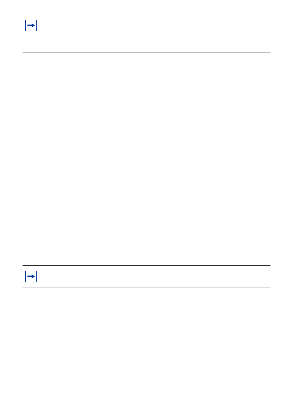
Chapter 15 Managing BCM50 Logs 249
BCM50 Administration Guide
To perform an immediate log transfer to a USB storage device
1Click the Administration tab, and then open the Logs folder.
2Click the Log Management task.
The Log Management panel opens.
3Click the Immediate Log Transfer tab.
4In the Transfer To selection field, select USB Storage Device.
5Click the Transfer button.
The Transfer To window opens.
6Select the log file categories that you want to include in the log file transfer. All the log files
associated with the selected categories will be transferred.
7Click the OK button.
A transfer window opens and displays applicable warnings.
8Click the Ye s button to initiate the transfer.
The Progress Update window opens. When the log files are transferred, the Transfer
Complete window opens.
9Click the OK button.
The log archive is saved in the location you specified.
Performing an immediate log transfer to your personal computer
To perform an immediate log transfer to your personal computer
1Click the Administration tab, and then open the Logs folder.
2Click the Log Management task.
The Log Management panel opens.
3Click the Immediate Log Transfer tab.
4In the Transfer To selection field, select My Computer.
5Click the Transfer button.
The Transfer To window opens.
6Select the log file categories that you want to include in the log file.
Note: Log archives written to external devices (except My Computer) have a
unique name based on the timestamp. This prevents earlier log archives from
being overwritten. A device will eventually reach its capacity if log archives are
not manually detected.
Note: The time required to transfer log files varies with the amount of log data
being collected and the speed of your devices and network.

250 Chapter 15 Managing BCM50 Logs
NN40020-600NN40020-600
7Click the OK button.
A confirmation window opens, and displays applicable warnings.
8Click the Ye s button to initiate the transfer.
The Progress Update window opens. When the log archive is ready to be saved, the The Save
window opens.
9Select the directory in which you want to save the log file transfer.
10 In the File Name field, enter the name of the log file followed by a .tar extension. For example,
log1.tar.
11 Click the Save button.
The Transfer Complete window opens.
12 Click the OK button.
The log file is saved as a .tar file in the location you specified.
Performing an immediate log transfer to a network folder
To perform an immediate log transfer to a network folder
1Click the Administration tab, and then open the Logs folder.
2Click the Log Management task.
The Log Management panel opens.
3Click the Immediate Log Transfer tab.
4In the Transfer To selection field, select Network Folder.
5Configure the Transfer to Network Folder attributes.
Note: If you do not specify a .tar extension, the transfer proceeds and the file will
be written to the specified location. The file, however, will be of an unknown type
and your utilities may not operate with it. Rename the file with the extension .tar
by right-clicking on the file and renaming it.
Note: The time required to transfer log files varies with the amount of log data
being collected and the speed of your devices and network.
Table 88 Configure the Transfer to Network Folder attributes
Attribute Action
Network Folder Enter the hostname or IP address of the network folder and the resource
name. For example, enter \\<server>\<resource>.
User Name Enter the user name associated with the network folder.
Password Enter the password associated with the network folder.
Directory Enter the path to the subdirectory, as applicable (optional).

Chapter 15 Managing BCM50 Logs 251
BCM50 Administration Guide
6Click the Transfer button.
The Transfer window opens.
7Select the log file categories that you want to include in the log file transfer.
8Click the OK button.
A confirmation window opens, and displays applicable warnings.
9Click the Ye s button to initiate the transfer.
The Progress Update window opens. When the log files are transferred, the Transfer
Complete window opens.
10 Click the OK button.
The log file is saved as a .tar file in the location you specified.
Performing an immediate log transfer to an FTP server
To perform an immediate log transfer to an FTP server
1Click the Administration tab, and then open the Logs folder.
2Click the Log Management task.
The Log Management panel opens.
3Click the Immediate Log Transfer tab.
4In the Transfer To selection field, select FTP Server.
5Configure the Transfer to FTP Server attributes.
6Click the Transfer button.
The Transfer window opens.
7Select the log file categories that you want to include in the log file transfer.
8Click the OK button.
A confirmation window opens, and displays applicable warnings.
Note: The time required to transfer log files varies with the amount of log data
being collected and the speed of your devices and network.
Table 89 Configure Transfer to FTP Server attributes
Attribute Action
FTP Server Enter the hostname or IP address of the FTP server.
User Name Enter the user name associated with the FTP server.
Password Enter the password associated with the FTP server.
Directory Enter the path to the subdirectory, as applicable (optional).

252 Chapter 15 Managing BCM50 Logs
NN40020-600NN40020-600
9Click the Ye s button to initiate the transfer.
The Progress Update window opens. When the log files are transferred, the Transfer
Complete window opens.
10 Click the OK button.
The log file is saved as a .tar file in the location you specified.
Performing an immediate log transfer to an SFTP server
To perform an immediate log transfer to an SFTP server
1Click the Administration tab, and then open the Logs folder.
2Click the Log Management task.
The Log Management panel opens.
3Click the Immediate Log Transfer tab.
4In the Transfer To selection field, select SFTP Server.
5Configure the Transfer to SFTP Server attributes.
6Click the Transfer button.
The Transfer window opens.
7Select the log file categories that you want to include in the log file transfer.
8Click the OK button.
A confirmation window opens, and displays applicable warnings.
9Click the Ye s button to initiate the transfer.
The Progress Update window opens. When the log files are transferred, the Transfer
Complete window opens.
Note: The time required to transfer log files varies with the amount of log data
being collected and the speed of your devices and network.
Note: You must set up the SFTP server to allow the BCM50 to communicate
with the SFTP server. For information about how to set up an SFTP server and
about SSH keys, see “BCM50 Security Policies” on page 79.
Table 90 Configure Transfer to SFTP Server attributes
Attribute Action
SFTP Server Enter the hostname or IP address of the SFTP server. For SFTP storage
locations, you must use an SCP server. BCM50 supports OpenSSH 3.7.
User Name Enter the user name associated with the SFTP server.
Directory Enter the path to the subdirectory, as applicable (optional).
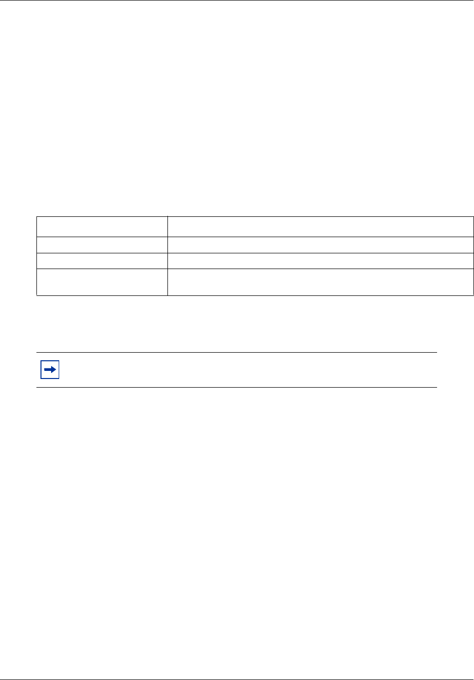
Chapter 15 Managing BCM50 Logs 253
BCM50 Administration Guide
10 Click the OK button.
The log file is saved as a .tar file in the location you specified.
Performing scheduled log transfers
You can schedule a log transfer for a future date or for a single transfer, or for recurring future
transfers. You can create multiple schedule entries. For example, you can transfer Operational logs
and System Information logs on a daily basis and transfer Diagnostic and Sensitive Information
logs on a weekly basis.
You can also modify or delete a scheduled log transfer.
Table 91 lists the information that is displayed in the Scheduled Log Transfer table.
For information about how to configure transfer to attributes, see the procedures in “Performing
immediate log archive transfers” on page 248.
To perform a scheduled log transfer to a storage location
1Click the Administration tab, and then open the Logs folder.
2Click the Log Management task.
The Log Management panel opens.
3Click the Scheduled Log Transfer tab.
The Scheduled Log Transfer panel opens.
4Click the Add button.
The Add Scheduled Transfer window opens.
5In the Transfer To selection field, select the location to which you want to transfer the log
files:
• Network Folder
• USB Storage Device
• FTP Server
• SFTP Server
Table 91 Information displayed in the Scheduled Log Transfer table
Column Description
Memo Displays the description of the scheduled log transfer.
Destination Displays the storage location for the log transfer.
Schedule Displays the date and time at which the log transfer will be transferred to
the specified storage location.
Note: You cannot schedule a log transfer to your personal computer. Use a
network folder, a USB storage device, an FTP server, or an SFTP server instead.

254 Chapter 15 Managing BCM50 Logs
NN40020-600NN40020-600
6Configure the Transfer To attributes. For information about how to configure Transfer To
attributes, see the procedures in “Performing immediate log archive transfers” on page 248.
7Click the OK button.
The Add Scheduled Transfer window opens.
8Select the log file categories that you want to include in the log file transfer.
9Configure the schedule attributes.
10 Click the OK button.
The scheduled log transfer is displayed in the Scheduled Log Transfer table.
To modify a scheduled log transfer
1Click the Administration tab, and then open the Logs folder.
2Click the Log Management task.
The Log Management panel opens.
3Click the Scheduled Log Transfer tab.
4In the Scheduled Log Transfer table, select a scheduled log file transfer.
5Click the Modify button.
The Modify Scheduled Transfer window opens.
6In the Destination field, modify the destination as appropriate.
7In the Memo field, modify the memo for the scheduled log transfer as appropriate.
8In the Optional Components area, modify the log file categories you want to include or
exclude from the transfer, as appropriate.
9Click the OK button.
The modified scheduled log transfer is displayed in the Scheduled Log Transfer table.
Table 92 Configure schedule attributes
Attribute Action
Memo Enter a note for the scheduled log transfer, as applicable.
Recurrence Select how often the scheduled transfer is to occur. Options are: Once,
Daily, Weekly, Monthly. Depending on the option you choose, the window
displays selections for the month and day of month. If you select Weekly,
days of the week check boxes appear so that you can select the days on
which the transfer will occur.
Month Select the month in which the scheduled transfer is to occur.
Day of Month Select the day of the month on which the scheduled transfer is to occur.
Time Select the time at which the scheduled transfer is to occur. Click the field to
display a Time box, where you can specify the hour, minute, second, and
whether the time occurs in morning or afternoon. Close the box when you
have finished specify the time.

Chapter 15 Managing BCM50 Logs 255
BCM50 Administration Guide
To delete a scheduled log transfer
1Click the Administration tab, and then open the Logs folder.
2Click the Log Management task.
The Log Management panel opens.
3Click the Scheduled Log Transfer tab.
4In the Scheduled Log Transfer table, select a schedule.
5Click the Delete button.
A confirmation window opens.
6Click the Ye s button.
The scheduled log transfer is deleted from the Scheduled Log Transfer table.
Transferring log files using the BCM50 Web page
You can transfer log files using the BCM50 Web page if you cannot access the BCM50 Element
Manager.
When you use the BCM50 Web page to transfer log files, you cannot choose the log file categories
that you will transfer; all the log files in all the categories will be transferred.
Using the BCM50 Web Page to transfer log files to your personal computer
1In your web browser, type the IP address of the BCM50 and click the Go button.
The login screen opens.
2Log in to the BCM50 using the same username and password that you use to log into a
BCM50 using the Element Manager.
The BCM50 Web page opens.
3Click the Administrators Applications link.
4Click the Retrieve Log Files link.
The Get Logs panel appears.
5Click one of the three options for file transfer: Transfer to My Computer, Store on USB
Memory, or Sent to.
6If you select the Send to radio button, select a destination from the drop-down list, otherwise,
go to the next step.
7Click the Click Here to Download Logs link.
The File Download screen opens.
8Click the Save button.
The Save As screen opens.
9Specify the location where you want to save the log file transfer, and enter a name for the file
in the File Name field.

256 Chapter 15 Managing BCM50 Logs
NN40020-600NN40020-600
10 Click the Save button.
The file is saved.
To use the BCM50 Web Page to transfer log files to other
destinations
1In your web browser, type the IP address of the BCM50 and click the Go button.
The login screen opens.
2Log in to the BCM50 using the same user name and password that you use to log into a
BCM50 using the BCM50 Element Manager.
The BCM50 Web page opens.
3Click the Administrators Applications link.
4Click the Retrieve Logs link.
5In the Get Logs area, select a destination for the retrieved logs:
• Transfer to my computer
• USB storage device
•Send to:
•FTP
•SFTP
• Windows Shared Folder
6If you selected a Send To option, configure the destination attributes.
7Click the Submit button.
A Working screen opens. When the log retrieval is complete, the screen displays “Done.”
8Click the Click Here to Download Logs link.
The File Download screen opens.
9Click the Save button to save the backup.tar file.
The Save As screen opens.
10 Specify the location where you want to save the zipped file, and enter a name for the file in the
File Name field. The file must have a .tar extension. For example, log2.tar.
Table 93 Configure destination attributes
Attribute Action
Remote Resource Enter the FTP or SFTP address or the network pathway, as appropriate.
For SFTP storage locations, you must use an SCP server. BCM50
supports OpenSSH 3.7.
Directory Enter the path of the directory to which you want to transfer the log files.
UserID Enter the user ID associated with the remote resource.
Password Enter the password associated with the remote resource. This option does
not apply when the destination is an SFTP server.

Chapter 15 Managing BCM50 Logs 257
BCM50 Administration Guide
11 Click the Save button.
The file is saved.
Extracting log files
Once you have transferred log files using the Element Manager or the BCM50 Web page, you can
extract the log files using the Element Manager Log Browser. The log files must be extracted from
the log archive before you can view them using the Element Manager Log Browser.
Before you extract log files, create a folder in your directory for each archive and then follow the
procedure below to extract the archive into the appropriate folder.
To extract log files using the Element Manager
1Left-click a network element. The network element may be connected or disconnected.
2Select File > View Network Element Logs.
The View Log File window opens.
3Select the directory or location that contains the transferred BCM50 log file tar archive.
4Select Network Element log archives (*.tar) in the File of Type field.
5Select the archive file, and then click the Open button.
A confirmation dialog box opens.
6Click the Ye s button to extract the contents of the zipped file.
A message dialog box opens and displays a success or error message for each extracted file.
7Click the OK button to acknowledge an individual message, or click OK to All to
acknowledge all messages once the extraction is complete. Alternatively, you can wait until
the extraction is complete, and then close the window.
Once the files are extracted, the View Log File window opens.
8Select a log file folder, for example operationalLogs.tar. Select .systemlog from the Save as
Type select field to show only log files that the Log Browser can display.
9Click the Open button.
The log file folder opens and the log files that it contains are displayed.
10 Select a .systemlog file or a .log file, and click the Open button.
The Log Browser opens and displays retrieval results for the selected log file.
Viewing log files using the Log Browser
The Log Browser is an application that you can use to search for and view information about log
events from different types of data sources. You can determine what type of information you want
to see and customize how you want to display the information.
You can view the following log files using the Element Manager Log Browser:

258 Chapter 15 Managing BCM50 Logs
NN40020-600NN40020-600
• all log files of type .systemlog
• most log files of type .log
• log files of type .txt or other file extensions that cannot be viewed using the Log Browser
You can use an application such as WordPad or Microsoft Word to view log files that you cannot
view using the Log Browser.
Table 94 lists the log files that you can view using the Log Browser.
The Log Browser contains the following areas:
• Retrieval Criteria area
• Retrieval Results list
• Log Details area
Retrieval Criteria area
The Retrieval Criteria area at the top of the Log Browser window displays a list of network
element and alarm attributes that you can use to define the criteria for browsing a selected log file.
You can display or close the Retrieval Criteria area by clicking on the arrow to the right of the
Retrieval Criteria field.
Retrieval criteria area specific to the log file that you are viewing. For example, .log files with four
columns have four possible retrieval criteria, while .systemlog files with six columns have six
possible retrieval criteria. You can define the criteria for browsing log files by selecting or
deselecting criteria.
Table 94 Log files and the Log Browser
Log File Can be viewed in the Log Browser?
Operational logs (.systemlog) Yes
Diagnostic logs Some can
System Information No
Sensitive Information No
Chapter 15 Managing BCM50 Logs 259
BCM50 Administration Guide
When you select an attribute from the Retrieval Criteria table, the Criteria Definition area to the
right of the table displays the corresponding details for the attribute you selected. You can select or
define the corresponding details.
You can click the Pane View buttons at the top right corner of the Retrieval Criteria area to display
a summary view of your selected criteria. This allows you to review selected criteria before you
retrieve the logs.
After you select an attribute, you can click the Clear button to remove it from the summary list,
click the Clear All button to remove selected attributes, or click the Retrieve button to initiate a
retrieval of log files according to the criteria you defined in the Retrieval Criteria area.
To specify retrieval criteria
1In the Retrieval Criteria table, select an attribute.
The Criteria Definition area displays the corresponding details for the selected attribute.
2Specify details for the selected attribute, as appropriate.
3Click the Retrieve button.
The results of the retrieval are displayed in the Retrieval Results list area.

260 Chapter 15 Managing BCM50 Logs
NN40020-600NN40020-600
Retrieval Results area
The Retrieval Results area displays the list of log information that was retrieved according the
criteria you selected in the Retrieval Criteria area. The information is displayed in a table that you
can sort by clicking column headings.
While the Log Browser is retrieving records, you can monitor the progress of the retrieval by
following the progress counter. This counter also displays the elapsed time and the number of
records found. You can stop the retrieval by clicking the Stop button.
The Log Browser displays all the records it has found, to a set maximum display limit. The
maximum display limit is 3000 records. Most log files exceed this limit; when this happens, you
cannot view the remaining records in the log file. If this is the case, try using filter criteria for a
specific date or dates to reduce the number of results.
You can sort the contents of the table by clicking the headings in the table. You can view details
about a log record by selecting a log record or multiple log records in the Retrieval Results area.
To filter information displayed in the Retrieval Results table, you can select or clear the check
boxes in the Show area below the Retrieval Results table. You can filter the results by alarm
severity: Debug, Info, Warn, or Error.
To filter information in the Retrieval Results table
1Retrieve log files. See the procedure “To specify retrieval criteria” on page 259.
2Below the Retrieval Results table, select or deselect any of the following filters:
• Critical — displays only Critical level
• Major— displays only Major level
• Minor — displays only Minor level
• Info — displays only Information level
• Warn — displays only Warning level
Log Details area
The Log Details area located below the Retrieval Results list displays the details for a selected log
record or multiple log records.
Viewing log details for a single log record
In the Retrieval Results list table, select a log record.
Log details for the selected log record are displayed in the Log Details area.
To view log details for multiple log records
1In the Retrieval Results list table, hold down the Shift key and select log records to select
multiple contiguous log records.

Chapter 15 Managing BCM50 Logs 261
BCM50 Administration Guide
Log details for the selected log records are displayed in the Log Details area, separated by
dashed lines.
2In the Retrieval Results list table, hold down the Control key and select log records to select
multiple non-contiguous log records.
Log details for the selected log records are displayed in the Log Details area, separated by
dashed lines.
3To toggle between viewing log details for single and multiple log records separated by a
dashed line, click the View Control buttons to the right of the Log Details area.
Viewing log files using other applications
Using the Element Manager Log Browser to view log files enables you to control how you view
log events by means of retrieval criteria and sorting tools. You can also view log files using other
applications if the Element Manager is not available. For example, you can use WordPad to view
.systemlog and .log files (tab delimited), or you can open the files using Microsoft Word or
Microsoft Excel.

262 Chapter 15 Managing BCM50 Logs
NN40020-600NN40020-600
263
BCM50 Administration Guide
Chapter 16
Accounting Management
This chapter describes how to manage accounts in a BCM50 system.
Overview of accounting management
BCM50 Call Detail Recording (CDR) is an application that records call activity. Each time a
telephone call is made to or from a BCM, detailed information about the call can be captured in a
Call Detail Recording file. You can use this information to:
• create billing records using third party software
• monitor call activity and therefore infer information about system utilization and other
indicators of system and services activity
About Call Detail Recording
You can use information collected by Call Detail Recording to determine whether the telephone
system is being used efficiently and to guard against abuse of the telephone system.
Call Detail Recording provides information about:
• the date and time of a call, and digits dialed
• the originating and the terminating line or station set
• whether an incoming call was answered
• elapsed time between origin of a call and when it was answered
• whether a call was transferred or put on hold
• call duration
• call charges
• calls associated with Account codes
• incoming call Calling Line Identification (CLID) information
• bearer Capability of the line in the call
• hospitality records for room occupancy status
• real Time records for ringing, DNIS, answered, unanswered, transferred, and released events
• for incoming calls with CLID information and Hospitality room occupancy status
Note: CDR monitors only incoming and outgoing calls. It does not monitor calls
within the BCM50 system.
264 Chapter 16 Accounting Management
NN40020-600NN40020-600
CDR information can be collected for all calls, outgoing calls only, specific long distance prefix
strings only, or calls associated with an account code only (to track calls for client billing
purposes). You can set parameters to specify whether additional information should be recorded,
such as hospitality information, including room occupancy status and room number information.
Using Call Detail Recording
BCM50 Call Detail Recording is covered in detail in the Call Detail Recording System
Administration Guide (NN40020-605). The Call Detail Recording System Administration Guide
covers the following topics:
• setting up the system so that the information you want to collect is written to the Call Detail
Record
• configuring CDR data file management and transfer
• installing and using the CDR Client for real-time monitoring of CDR records
You can configure the BCM50 to create a new CDR file on a daily, weekly, or monthly basis, or
when the file reaches a specified size. You can retrieve CDR files by configuring the BCM50 to
send (“push”) the files to a remote system or by using a toolkit application to retrieve (“pull”) the
files from a remote system.
CDR Toolkit
A CDR Toolkit is provided with the BCM50 to enable third-party developers to retrieve BCM50
Call Detail Record data files and integrate them into their applications.
Note: Two CallPilot reports are included in the data transfer when CDR data files
are “pulled” or “pushed” from the BCM50 system. These are the Call Pilot
Mailbox activity report and the All Mailbox Activity Report.

265
BCM50 Administration Guide
Chapter 17
Managing BCM50 Software Updates
This chapter contains information about managing BCM50 software updates.
During the lifecycle of the BCM50, you can apply software updates to the BCM50 unit to
introduce new functionality. Between software upgrades, you may find it necessary to apply
software updates to resolve field issues. Both software upgrades and software updates are applied
in the same manner.
Using the BCM50, you can:
• obtain software updates from different storage locations, such as an FTP site or USB storage
device
• view the software upgrade and update history of the BCM50
• apply and, in some cases, remove software updates
• view the software inventory of the BCM50
• apply software updates at a scheduled time
Overview of BCM50 software updates
Using the Software Management task, an administrator can view and manage software updates
and upgrades to the BCM50.
The Software Management interface consists of three panels:
• Software Updates — used to manage the application of software updates to the BCM50
• Software Update History — used to view the history of updates that have been applied to the
BCM50, and to remove an applied update
• Software Inventory — used to view a complete list of software components, their version, and
the functional group to which they belong
Obtaining software updates
Before you can apply a software update to your BCM50, you must obtain the software update and
unzip the file. Authorized Nortel partners can download BCM50 software updates from the Nortel
Technical Support web page.
To obtain updates from the Nortel Technical Support Web page
1In your web browser, enter <address> and then click the Go button.
The Nortel Technical Support Web page opens.
2Download the required updates.
3Create a directory for each update and unzip the downloaded file into a directory.
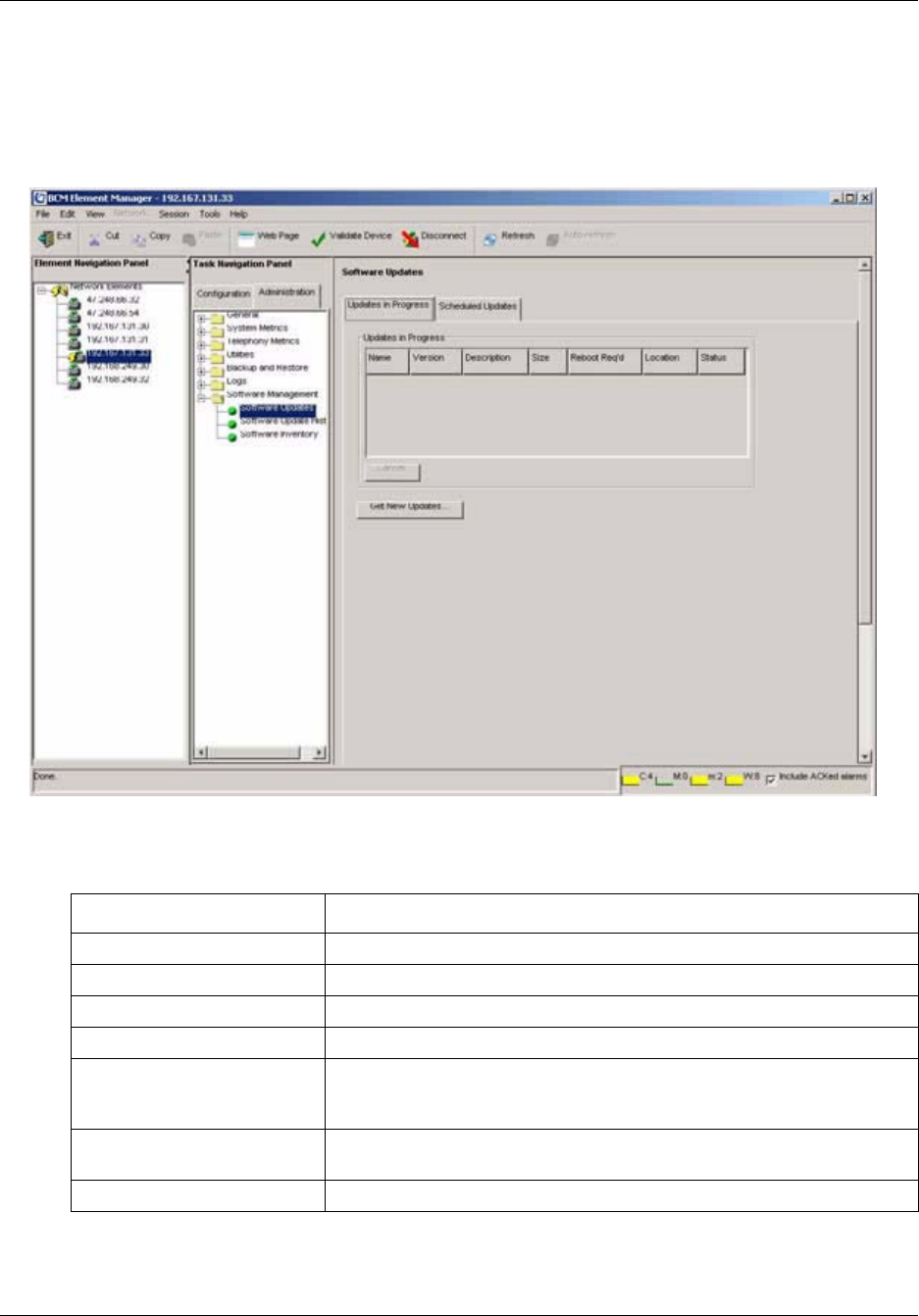
266 Chapter 17 Managing BCM50 Software Updates
NN40020-600NN40020-600
Viewing software updates in progress
You can view the status of software updates that are transferring or waiting to be transferred, or
waiting to be applied.
Figure 38 Software Updates panel
Table 95 lists the information that is available on the Updates in Progress table.
Table 95 Information about updates in progress
Detail Description
Name The name of the software update.
Version The version of the software update.
Description A brief description of the software update.
Size The size of the software update, in KB.
Reboot Req’d Displays whether the software update causes the BCM50 to reboot when
the update has been applied. If a reboot is required, the check box is
checked.
Location The location from which the software update is being retrieved, for example
an FTP server or a network folder.
Status The status of the update. See Table 96 for information.

Chapter 17 Managing BCM50 Software Updates 267
BCM50 Administration Guide
Table 96 lists the statuses of software updates.
You can change the order of columns in the Updates in Progress table by clicking a column
heading and dragging it to a different place in the table.
To view details about software updates in progress
1In the task panel, click the Administration tab.
2Open the Software Management folder, and then click the Software Update task.
The Software Update panel opens and displays the Updates in Progress tab.
3View the details in the Updates in Progress table.
Once a software update is complete, the entry is removed from the Updates in Progress table
and a new entry is added to the Software History table to document the installation of the
software update.
Applying software updates
Once you have downloaded a software update from the Nortel Technical Support Web page, you
can apply it to the BCM50.
You can apply one software update at a time. For multiple software updates, repeat the following
procedure until each update has been applied. When you have several updates to apply, any
software updates that require the system to reboot should be applied last. Information about each
update is available when you click the Show Details button.
Table 96 Software update statuses
Status Description
Available The software update is available to be applied to the BCM50. Only an
Available software update can be applied to the BCM50.
Invalid A newer version of software has been applied to the BCM50,or a problem
has been detected with the software update, and has rendered this
software update invalid. An update will also be listed as invalid if a
requirement for the update is not met; reequirements may include
keycodes or a related update.
Installed The software update has been applied to the BCM50.
In Progress The software update is in the process of being applied to the BCM50. An
update may be In Progress for up to 15 minutes, depending on the size of
the update file.
Scheduled A download of the software update is scheduled.

268 Chapter 17 Managing BCM50 Software Updates
NN40020-600NN40020-600
Applying a software update is a two-part process:
1You transfer a software update to the BCM50, which validates the integrity of the software
update and ensures that the BCM50 meets prerequisites for applying the software update.
2You apply the software update to the BCM50, which then brings the update into service.
You can apply software updates that have a status of “Available.”
The application of software generates an information event, but does not generate an alarm
condition.
You can apply updates from the following storage locations:
• a USB storage device
• your personal computer
• a network folder
• an FTP server
• an HTTP server, with or without SSL
You can view details about a software update before you apply it. You can apply a software
immediately or schedule the update for a future time.
Applied software is displayed in the Software Update History table.
Caution: Applying a software update to the BCM50 may be a service-affecting
operation. Nortel recommends that you schedule updates for low-traffic hours.
Refer to the detailed information provided with each update to understand its
impact on the system.
Caution: In the case of some software updates, the BCM50 automatically
restarts as soon as an update has been applied, without prompting or confirmation.
These updates are identified as Reboot Req’d in the Find Software Updates
window.
Note: Software update files may range in size from several hundred kilobytes to
many megabytes, depending on the software components addressed by the
software update. The amount of time required to transfer the software update to
the BCM50 before you apply the update depends on the size of the software
update file and on the type of connectivity between the location of the software
update and the BCM50 being updated.
Chapter 17 Managing BCM50 Software Updates 269
BCM50 Administration Guide
Applying an update from your personal computer
To apply an update from your personal computer
1In the task panel, click the Configuration tab.
2Select System>Date and Time and verify that the date, time, and time zone are correctly set.
3In the task panel, click the Administration tab.
4Open the Software Management folder, and then click the Software Update task.
The Software Update panel opens. The Updates in Progress tab is open.
5Click the Get New Updates button.
The Get New Updates window opens.
6Select My Computer from the Retrieve From selection field.
7Click the Browse button.
The Select window opens.
8Navigate to the directory where you unzipped the update file and click Select.
9Select the location from which you want to retrieve the update.
The Find Software Updates window opens and displays a list of updates found in the
specified location
10 Select an update. The update must have a status of “Available.”
11 To view details about the update, click the Show Details button.
The Details for Update window opens and displays any details about the update. Click the
OK button to close the details window.
Caution: Applying a software update to the BCM50 is a service-affecting
operation. Nortel recommends that you schedule updates for low-traffic hours.
Caution: If a software update has a checkmark applied against it in the Reboot
Req’d column of the Find Software Updates window, the BCM50 automatically
restarts as soon as the update is applied. You do not receive a reboot confirmation
before the reboot occurs.
Note: The Select dialog displays directories only and does not show the contents
of the directories.
Note: If the information in the Find Software Updates window indicates that
you are applying an upgrade rather than an update, you will need to generate a
keycode before proceeding.

270 Chapter 17 Managing BCM50 Software Updates
NN40020-600NN40020-600
12 Click the Apply button to apply the update.
A warning dialog box opens.
13 Click the OK button.
The Software Update Complete confirmation window opens.
14 A dialog box opens to display the options available for this update. The options available
depend on the update that you are applying. Select the appropriate options and click the OK
button. If no options are available, click the OK button to continue.
15 The Updates in Progress table lists the update as In Progress. Click the OK button.
A software update that has the Reboot Required field checked automatically restarts the
BCM50 once the update has been applied.
Applying a software update from a USB storage device
Before you apply an update from a USB storage device, make sure that:
• the USB storage device is formatted as a FAT32 device
• you know the path to the location of the updates on the device
• the device is connected to the BCM50
• the size of the software update is not greater than the capacity of the storage device
To apply a software update from a USB storage device
1In the task panel, click the Administration tab.
2Open the Software Management folder, and then click the Software Update task.
The Software Update panel opens. The Updates in Progress tab is open.
3Click the Get New Updates button.
The Get New Updates window opens.
4Select USB Storage Device from the Retrieve From selection field.
5Enter the path to the location of the update in the Directory field. You must enter the complete
path.
Caution: Applying a software update to the BCM50 is a service-affecting
operation. Nortel recommends that you schedule updates for low-traffic hours.
Caution: If a software update has a checkmark applied against it in the Reboot
Req’d column of the Find Software Updates window, the BCM50 will
automatically reboot as soon as the update has been applied. You will not receive a
reboot confirmation before the reboot occurs.
Caution: Do not remove the USB storage device until the update is applied.
Removing the device before the update has been applied may seriously harm the
integrity of your system.
Chapter 17 Managing BCM50 Software Updates 271
BCM50 Administration Guide
6Click the OK button.
The Find Software Updates window opens and displays a list of updates found in the
specified location.
7Select an update. The update must have a status of “Available”.
8Click the Apply button.
A confirmation window opens.
9Click the Ye s button.
The Software Update Complete confirmation window opens.
10 Click the OK button.
The Updates in Progress table lists the update as “In Progress”. A software update that has
the Reboot Required field checked will automatically reboot the BCM50 once the update has
been applied.
Applying an update from a network folder
To apply an update from a network folder
1In the task panel, click the Administration tab.
2Open the Software Management folder, and then click the Software Update task.
The Software Update panel opens. The Updates in Progress tab is open.
3Click the Get New Updates button.
The Get New Updates window opens.
4Select Network Folder from the Retrieve From selection field.
5Configure the network folder attributes.
Caution: Applying a software update to the BCM50 is a service-affecting
operation. Nortel recommends that you schedule updates for low-traffic hours.
Caution: If a software update has a checkmark applied against it in the Reboot
Req’d column of the Find Software Updates window, the BCM50 will
automatically reboot as soon as the patch has been applied. You will not receive a
reboot confirmation before the reboot occurs.
Table 97 Configure Network Folder attributes
Attribute Action
Network Folder Enter the IP address or host name of the network folder and the resource
name. For example, enter \\<hostname>\<resource>.
User Name Enter the user name associated with the shared folder.
Password Enter the password of the user.
Directory Enter the path to the subdirectory of the network folder (optional).
272 Chapter 17 Managing BCM50 Software Updates
NN40020-600NN40020-600
6Click the OK button.
The Find Software Updates window opens and displays a list of updates found in the
specified location.
7Select an update. The update must have a status of “Available”.
8Click the Apply button.
A confirmation window opens.
9Click the Ye s button.
The Software Update Complete confirmation window opens.
10 Click the OK button.
The Updates in Progress table lists the update as “In Progress”. A software update that has
the Reboot Required field checked will automatically reboot the BCM50 once the update has
been applied.
Applying an update from an FTP server
To apply an update from an FTP server
1In the task panel, click the Administration tab.
2Open the Software Management folder, and then click the Software Update task.
The Software Update panel opens. The Updates in Progress tab is open.
3Click the Get New Updates button.
The Get New Updates window opens.
4Select FTP Server from the Retrieve From selection field.
5Configure the FTP Server attributes.
Caution: Applying a software update to the BCM50 is a service-affecting
operation. Nortel recommends that you schedule updates for low-traffic hours.
Caution: If a software update has a checkmark applied against it in the Reboot
Req’d column of the Find Software Updates window, the BCM50 will
automatically reboot as soon as the update has been applied. You will not receive a
reboot confirmation before the reboot occurs.
Table 98 Configure FTP Server attributes
Attribute Action
FTP Server Enter the IP address or host name of the remote computer, and the port
number if required.
User Name Enter the user name associated with the FTP server.
Chapter 17 Managing BCM50 Software Updates 273
BCM50 Administration Guide
6Click the OK button.
The Find Software Updates window opens and displays a list of updates found in the
specified location.
7Select an update. The update must have a status of “Available”.
8Click the Apply button.
A confirmation window opens.
9Click the Ye s button.
The Software Update Complete confirmation window opens.
10 Click the OK button.
The Updates in Progress table lists the update as “In Progress”. A software update that has
the Reboot Required field checked will automatically reboot the BCM50 once the update has
been applied.
Applying an update from an HTTP server
To apply an update from an HTTP server
1In the task panel, click the Administration tab.
2Open the Software Management folder, and then click the Software Update task.
The Software Update panel opens. The Updates in Progress tab is open.
Password Enter the user name associated with the FTP server.
Directory Enter the path to the location of the update. The path is relative to the root
of the FTP server you are logging into. For example, if the root of the FTP
server you have logged into is /public and your patches are located under
/public/patches, you would enter patches as the directory.
Caution: Applying a software update to the BCM50 is a service-affecting
operation. Nortel recommends that you schedule updates for low-traffic hours.
Caution: If a software update has a checkmark applied against it in the Reboot
Required column of the Find Software Updates window, the BCM50 will
automatically reboot as soon as the update has been applied. You will not receive a
reboot confirmation before the reboot occurs.
Note: The BCM50 supports only Apache web servers as HTTP servers. You
must enable automatic index generation on the HTTP server for the directory
where the update is located.
Table 98 Configure FTP Server attributes
Attribute Action

274 Chapter 17 Managing BCM50 Software Updates
NN40020-600NN40020-600
3Click the Get New Updates button.
The Get New Updates window opens.
4Select HTTP Server from the Retrieve From selection field.
5Configure the HTTP Server attributes.
6Click the OK button.
The Find Software Updates window opens and displays a list of updates found in the
specified location.
7Select an update. The update must have a status of “Available”.
8Click the Apply button.
A confirmation window opens.
9Click the Ye s button.
The Software Update Complete confirmation window opens.
10 Click the OK button.
The Updates in Progress table lists the update as In Progress. A software update that has the
Reboot Required field checked will automatically reboot the BCM50 once the update has
been applied.
Creating and modifying scheduled software updates
You can apply a software update to the BCM50 at a future date by creating a schedule. A
scheduled software update is displayed in the Scheduled Updates tab. You can schedule only one
update at a time.
You can view, modify, or delete a scheduled software update. When you schedule a software
update, the device where the update is stored (such as a USB device) must be connected to the
BCM50 when you create the schedule.
Table 99 Configure HTTP Server attributes
Attribute Action
HTTP Server Enter the IP address or host name of the remote computer, and the port
number if required.
Use HTTPS Check this box if the HTTP server requires SSL.
User Name Enter the user name associated with the HTTP server.
Password Enter the password of the user.
Directory Enter the path to the location of the update. The path is relative to the root
of the HTTP server you are logging into. For example, if the root of the
HTTP server you have logged into is /public and your patches are located
under /public/patches, you enter patches as the directory.

Chapter 17 Managing BCM50 Software Updates 275
BCM50 Administration Guide
Table 100 lists the information that is displayed about scheduled software updates in the
Scheduled Software Updates table.
Table 101 lists the statuses of scheduled software updates.
Table 100 Information about scheduled software updates
Columns Description
Name The name of the update.
Version The version of the update.
Description A brief description of the update.
Size The size of the software update, in kilobytes.
Reboot Req’d Displays whether the software update causes the BCM50 to reboot when
the update has been applied. If a reboot is required, the check box is
checked.
Location The storage location of the update. For example, FTP server.
Status The status of the update. See Table 101 for information.
Retrieve The date and time at which the update will be retrieved.
Apply The date and time at which the update will be applied.
Table 101 Statuses of scheduled software updates
Status Description
Scheduled The software update has been scheduled.
Removed The scheduled software update has been deleted.
Modified The scheduled software update has been modified.
Applied The scheduled software update has been applied to the BCM50.

276 Chapter 17 Managing BCM50 Software Updates
NN40020-600NN40020-600
Creating a scheduled software update
To create a scheduled software update
1In the task panel, click the Administration tab.
2Open the Software Management folder, and then click the Software Update task.
The Software Update panel opens. The Updates in Progress tab is open.
3Click the Scheduled Updates tab.
The Scheduled Software Updates panel opens.
4Click the Add button.
The Get New Updates window opens.
5In the Retrieve From selection field, select the location where the software update is stored:
• USB Storage Device
• My Computer
• Network Folder
• FTP Server
• HTTP Server
6Select an update location and/or complete the appropriate access information. For more
information, see the procedures in “Applying software updates”.
7Click the OK button.
The New Updates Found window opens and displays a list of updates found in the specified
location.
8Select an update. The update must have a status of “Available”.
9To view the details for an update, click the Show Details button.
The Details for Update window opens and displays any details about the update. Click the
OK button to close the details window.
10 Click the Schedule button to create a schedule.
The Schedule Software Updates window opens.
11 Click the Retrieve field to select a date and time at which to retrieve the update. A calendar
window opens.
12 Select a retrieve date and time, and then close the window.
Caution: Applying a software update to the BCM50 is a service-affecting
operation. Nortel recommends that you schedule updates for low-traffic hours.
Caution: If a software update has a checkmark applied against it in the Reboot
Req’d column of the New Updates Found window, the system will automatically
reboot as soon as the patch has been applied. You will not receive a reboot
confirmation before the reboot occurs.

Chapter 17 Managing BCM50 Software Updates 277
BCM50 Administration Guide
13 Click the Apply field to select a date and time at which to apply the update. A calendar
window opens.
14 Select an apply date and time, and then close the window.
15 Click the OK button.
The software update is added to the Scheduled Software Updates table. The status of the
update is “Schedule”.
Modifying a scheduled software update
To modify a scheduled software update
1In the task panel, click the Administration tab.
2Open the Software Management folder, and then click the Software Update task.
The Software Update panel opens. The Updates in Progress tab is open.
3Click the Scheduled Updates tab.
4In the Scheduled Software Updates table, select a scheduled update.
5Click the Modify button.
The Modify Scheduled Software Update window opens.
6Click the Retrieve field to select a date and time at which to retrieve the update. A calendar
window opens.
7Select a retrieve date and time, and then close the window.
8Click the Apply field to select a date and time at which to apply the update. A calendar
window opens.
9Select an apply date and time, and then close the window.
10 Click the OK button.
The modified software update is displayed in the Scheduled Software Updates table. The
modification may take a few minutes to appear in the table.
Caution: Applying a software update to the BCM50 is a service-affecting
operation. Nortel recommends that you schedule updates for low-traffic hours.
Caution: If a software update has a checkmark applied against it in the Reboot
Req’d column of the New Updates Found window, the BCM50 will automatically
reboot as soon as the update has been applied. You will not receive a reboot
confirmation before the reboot occurs.

278 Chapter 17 Managing BCM50 Software Updates
NN40020-600NN40020-600
To delete a scheduled software update
1In the task panel, click the Administration tab.
2Open the Software Management folder, and then click the Software Update task.
The Software Update panel opens. The Updates in Progress tab is open.
3Click the Scheduled Updates tab.
4In the Scheduled Software Updates table, select a scheduled update.
5Click the Delete button.
The Confirm Delete window opens.
6Click the Ye s button to delete the update.
The scheduled update is removed from the Scheduled Software Update table.
Viewing a history of software updates
Using the Software Update History panel, you can view the history of all software updates,
including software upgrades, that have been applied to the BCM50 since the it was shipped.
You can:
• view the current software release level of the BCM50
• view a history of all software updates (including upgrades) applied to the BCM50
• view release notes that apply to a particular software update
• remove certain software updates from the BCM50
Table 102 lists the information displayed in the Software Update History table.
To view the software update history
1In the task panel, click the Administration tab.
2Open the Software Management folder, and then click the Software Update History task.
The Software Update History panel opens.
Table 102 Information displayed in the Software Update History table
Columns Description
Date The date and time that the software update was applied.
Category The software update category (Scheduled, Removed, Modified, Applied).
Name The name of the software update.
Version The version of the software update.
Description A brief description of the software update.
Removeable Indicates whether the software update can be removed from the BCM50. If
it can be removed, the check box is checked.

Chapter 17 Managing BCM50 Software Updates 279
BCM50 Administration Guide
3View the updates in the Software Update History table. If software updates have not been
applied to your BCM50, the table is empty.
4To view release notes about a particular software update, select the update in the table.
Release notes containing details about the software update are displayed in the Release Notes
panel below the table.
Removing software updates
You may find that you need to remove a software update that has been applied to the BCM50. Not
all software updates can be removed; whether a software update can be removed depends on the
the particular software update.
Removing a software update does not remove the software itself from the BCM50; it only returns
the software components of the software update to a previous software version. You must have
administrator privileges to remove a software update from the BCM50.
Removing a software patch or upgrade from the BCM50 is a service-affecting operation. All
services running on the system will be stopped. Consequently, Nortel recommends that you
schedule removal of updates for low-traffic periods.
If a software update is applied to a BCM50 and then removed, this information is displayed in the
Software Update History table. A removal operation is logged by the BCM50, but does not
generate an alarm condition.
You can remove a software update if the update has a checkmark in the Removeable column of the
Software Update History table.
Removing a software update
To remove a software update
1In the task panel, click the Administration tab.
2Open the Software Management folder, and then click the Software Update History task.
The Software Update History panel opens.
3Select an update in the Software Update History table. The update must have a checkmark
against it in the Removeable column.
4Click the Remove Software Update button.
A confirmation window opens.
5Click Ye s .
The Category column in the Software Update History table displays “Patch Removed” for
the removed software update.
Caution: Removing a software patch or upgrade from the BCM50 is a
service-affecting operation. All services running on the system will be stopped.
Consequently, Nortel recommends that you schedule removal of updates during
low-traffic hours.

280 Chapter 17 Managing BCM50 Software Updates
NN40020-600NN40020-600
Viewing the inventory of BCM50 software
BCM50 software is organized into software components that you can individually update as
required. The version of each software component is tracked so that you can determine the exact
software release level of a BCM50 to the component level.
You can view the complete inventory of software installed on the BCM50. The Software
Inventory table displays all the software components installed on the system, the functional group
and the software version of each component.
Table 103 lists the information displayed in the Software Component Version Information table.
You can change the order of the information displayed in the table by clicking a column heading
and dragging it to a new place in the table. You can also sort the information in a column by
descending or ascending order, by clicking the column heading.
To view the BCM50 software inventory
1In the task panel, click the Administration tab.
2Open the Software Management folder, and then click the Software Inventory task.
The Software Inventory panel opens.
3View the details in the Software Component Version Information table.
Table 103 Information displayed in the Software Component Version Information table
Column Description
Component The name of the software component installed on the BCM50. For
example, backup-recovery.
Group The functional group to which the software component belongs. For
example, Operating System.
Version The version of the software component.

281
BCM50 Administration Guide
Appendix A
Management Information Bases
This appendix describes the Management Information Bases (MIBs) supported by the BCM50.
A MIB is a virtual information store that contains a collection of objects that are managed using
Simple Network Management Protocol (SNMP). The MIB is software that defines the data
reported by a computing or network device and the extent of control over that device.
About SNMP MIBs
A MIB enables access to the managed objects of a system. MIBs are managed using a network
management protocol, such as Simple Network Management Protocol (SNMP).
The BCM50 main unit supports the following MIBs:
• MIB-II (RFC1213)
• SNMP-FRAMEWORK-MIB (RFC2261)
• ENTITY-MIB (RFC273)
• HOST-MIB (RFC2790)
• IF-MIB (RFC2863)
• SNMPv2-MIB
• IANAifType-MIB
• BCM Small Site Common MIB
• BCM Small Site Events MIB
BCM50 units equipped with an integrated router (BCM50e, BCM50a, BCM50be, and BCM50ba)
also support RFC 1231 — MIB-II and a private MIB. For more information, see the BCM50
Networking Configuration Guide (NN40020-603).
You can use BCM MIBs to monitor the network element; you cannot use BCM MIBs to configure
the element. Read-only access is provided for all supported MIB objects.
MIB file descriptions
BCM50 MIBs belong to two categories:
• Standard MIBs — include MIB-II (RFC1213), SNMP-FRAMEWORK-MIB (RFC2261),
ENTITY-MIB (RFC273), HOST-MIB (RFC2790), IF-MIB (RFC2863), SNMPv2-MIB, and
IANAifType-MIB
• Nortel MIBs — include BCM Small Site MIB and BCM Small Site Events MIB

282 Appendix A Management Information Bases
NN40020-600NN40020-600
Table 104 lists the file names and file descriptions of each supported standard MIB.
Table 105 lists the file names and file descriptions of each supported Nortel MIB.
Table 104 MIB file descriptions for standard MIBs
MIB File Name Notes
MIB-II rfc1213-mib.mib This MIB defines the Management Information
Base (MIB-II) for use with network
management protocols in TCP/IP-based
internets.
SNMP-FRAMEWORK-MIB snmp-framework-mib.mib This is the SNMP Management Architecture
MIB. This standard MIB displays parameters
related to the SNMP agent on the BCM50.
ENTITY-MIB entity-mib.mib This MIB defines physical and logical system
components on the BCM and associations
between these components.
HOST-MIB host-resources-mib.mib This MIB is used to manage host systems. It is
useful for monitoring resource usage and
system performance.
IF-MIB if-mib.mib This MIB describes generic objects for network
interface sub-layers.
SNMPv2-MIB snmpv2-mib.mib This MIB defines basic SMI types and
structures used by other MIBs.
IANAifType-MIB ianaiftype-mib.mib This MIB defines types which are used by
IF-MIB.
Table 105 MIB file descriptions for Nortel MIBs
MIB File Name Notes
Small Site MIB smallsite-common-mib.mib This MIB defines the upper-level hierarchy of
an enterprise(1).nortel(562) sub-branch called
smallsite. This Nortel MIB is the basis for
several Nortel smallsite products. In the
BCM50, this MIB is a prerequisite for the Small
Site Events MIB.
Small Site Events MIB smallsite-events-mib.mib This MIB defines the events (traps) that the
Small Site product or component can use. This
MIB describes the events generated by the
BCM. This MIB contains fields such as eventId,
eventSource, eventTime, and EventDescr.

Appendix A Management Information Bases 283
BCM50 Administration Guide
Accessing, compiling, and installing MIB files
You access MIB files from the BCM50 Web Page. You can also access BCM50 MIB files as a
zipped file from the Nortel Customer Service Site.
To access MIB files from the BCM50 Web Page
1Go to the BCM50 Web Page.
2Click the Administration Applications link.
3Click BCM MIBs.
4Click Download Device MIBs.
A File Download dialog box displays.
5Click Save to download the file.
To access MIB files from the Nortel Customer Service Site
1In your browser, go to http://www.nortel.com.
The Nortel Customer Service Site home page opens.
If you used the direct link, the Technical Support page opens. Go to step 5.
2Select the Support & Training navigation menu, and then select Technical Support,
Software Downloads.
The Technical Support page opens. The Browse Product Support tab displays Product
Finder fields.
3In area 1, select Product Families from the selection field, and then select BCM from the
selection box.
4In area 2, select Business Communications Manager (BCM).
5In area 3, select Software.
6Click the Go link.
The Software tab opens.
7In the by Title/Number Keyword field, enter mib, and then press the Enter key.
A list of MIBs is displayed.
8In the Title column, click the BCM50 MIB link.
The Software Detail Information page opens.
9Right-click the BCM50 MIB link, and select Save Target As.
The File Download dialog box opens.
Note: You can use a MIB browser to load MIB information so that you
can browse the structure of a MIB. An example of a MIB browser is
Microsoft Operations Manager (MOM). Each MIB browser has its own
MIB compilation tool.

284 Appendix A Management Information Bases
NN40020-600NN40020-600
10 In the Save As dialog box, select the file or folder in which you want to save the MIB zip file,
and then click the Save button.
The MIB zip file is saved to your personal computer.
Compiling and installing Nortel MIB files
Complete the compilation procedure, in the following order:
asmallsite-common-mib.mib
bsmallsite-events-mib.mib
Compiling and installing standard MIB files
Complete the compilation procedure, in the following order:
arfc1213-mib.mib
bsnmp-framework-mib.mib
centity-mib.mib
dhost-resources-mib.mib
eif-mib.mib
Small Site Common MIB
The device sysObjectIDs are defined in the BCM Small Site Common MIB. The sysObjectIDs are
defined for the BCM50 main unit. Table 106 summarizes the sysObjectID assignments.
Note: Small Site MIBs have definitions for the binding values of the
BCM50 SNMP traps. For more information, see Table 108 in this
section.
Note: BCM50 files are created and released in a MicroSoft Windows
environment so that when these files are copied and transferred to a
UNIX environment the last carriage return can be deleted. In this case,
you can get an “END is not found” error message during the
compilation. Open the MIB file with a UNIX text editor and add a
carriage return at the end of the word “END”.
Table 106 sysObjectID assignments
Model Main Unit sysObjectID Integrated Router sysObjectID
BCM50 and BCM50b 1.3.6.1.4.1.562.37.1.7 —
BCM50a and BCM50ba 1.3.6.1.4.1.562.37.1.7 1.3.6.1.4.1.562.37.1.5
BCM50e and BCM50be 1.3.6.1.4.1.562.37.1.7 1.3.6.1.4.1.562.37.1.6

Appendix A Management Information Bases 285
BCM50 Administration Guide
Small Site Events MIB
The Small Site Events MIB defines events (SNMP traps) that can be used by any Small Site
product or component. BCM50 traps can be captured and viewed using a standard SNMP fault
monitoring framework or trap watcher.
SNMP traps are generated by the BCM50 if you have enabled SNMP for specific BCM50 alarms.
You configure SNMP settings using the Alarm Settings task in the Element Manager. For
information about how to configure SNMP traps, see Chapter 8, “Managing BCM50 with SNMP,”
on page 137.
Table 107 lists the BCM50-specific SNMP trap fields for Small Site Event MIBs.
Table 108 lists the BCM50-specific SNMP variable bindings.
Table 107 BCM50-specific SNMP trap fields for the Small Site Event MIB
Trap Field Description
Enterprise OID identifies the product
(iso.org.dod.internet.private.enterprises.nortel.smallsite.common.events[1.3.
6.1.4.1.562.37.3.1])
Agent address IP address of one of the BCM50 interfaces
Generic trap type 6 for Enterprise-specific traps
Specific trap type 1 = eventInfo trap type
2 = eventWarning trap type
3 = eventError trap type
Time stamp the system up time
Table 108 BCM50-specific variable bindings
Trap Field Description
Binding #1 Contains the corresponding alarm ID.
OID: 1.3.6.1.4.1.562.37.3.1.1.0
Binding #2 Contains the name of the software component that generated the alarm
(trap). This is in the 3-part DN format defined in the Nortel Common Alarm
Framework. The 3-part DN is in the format:
systemId=BCM, entityId=System Name, subEntityId=Component Name
OID: 1.3.6.1.4.1.562.37.3.1.2.0
Binding #3 Contains the alarm (trap) Date and Time
OID: 1.3.6.1.4.1.562.37.3.1.3.0
Binding #4 Contains the alarm (trap) problem description
OID: 1.3.6.1.4.1.562.37.3.1.4.0

286 Appendix A Management Information Bases
NN40020-600NN40020-600

287
BCM50 Administration Guide
Appendix B
List of BCM50 alarms
This appendix contains a list of alarms generated by the BCM50 system.
List of BCM50 alarms
Table 109 lists BCM50 alarms. The table includes the default handling of each alarm with respect
to the Alarms table, the alarm set, LEDs, and SNMP traps.
You can customize whether each alarm appears in the Alarms table or is sent as an SNMP trap in
accordance with your business requirements.
Table 109 List of alarms
#
Alarm
ID Severity
Component
Name
Problem
Description
Problem
Resolution Alarm SNMP LED
Alarm
Set
118 minor Core
Telephony
Core Telephony -
Unable to process
calls.
Reboot system and
contact your local
support group.
Yes No No No
231 critical Core
Telephony
Core Telephony -
Media Bay Module
firmware download
failed.
Power down the
system and check
the DTM hardware
and the expansion
chassis connections.
If problem persists
replace the DTM or
expansion chassis
hardware.
Yes Yes Yes Yes
332 critical Core
Telephony
Core Telephony -
BRI module is
primary clock
instead of DTM
module.
Configure the DTM
module as primary
clock in your system.
BRI clock
specifications are
not acceptable for
DTM connections to
the public network.
Yes Yes Yes Yes
433 critical Core
Telephony
Core Telephony -
Cold restart has
occurred causing
loss of telephony
data.
Check configuration
change logs to see if
this was user
initiated. If not
contact your local
support group.
Yes Yes Yes Yes
534 warning Core
Telephony
Core Telephony -
Media Bay Module
firmware download
started.
No Action Required. Yes No No No

288 Appendix B List of BCM50 alarms
NN40020-600NN40020-600
635 critical Core
Telephony
Core Telephony -
Media Bay Module
firmware download
failure.
Power down the
system and check
the expansion
chassis connections.
Check for
corresponding alarm
31 or 79 to
determine which
module is having
issues. If problem
persists replace
corresponding
hardware.
Yes Yes Yes Yes
736 critical Core
Telephony
Core Telephony -
Media Bay Module
firmware download
failure.
Power down the
system and check
the expansion
chassis connections.
Check for
corresponding alarm
31 or 79 to
determine which
module is having
issues. If problem
persists replace
corresponding
hardware.
Yes Yes Yes Yes
837 critical Core
Telephony
Core Telephony -
Failure to download
market profile/
protocol data from
the Persistent Data
Repository.
Restart system and
contact your local
support group.
Yes Yes Yes Yes
939 critical Core
Telephony
Core Telephony -
Persistent Data
Repository
corruption in the
market profile area.
Perform a restore
with a known good
backup. If problem
persists contact your
local support group.
Yes Yes Yes Yes
10 40 critical Core
Telephony
Core Telephony -
"Unavailable
Seconds Error" long
term alarm
threshold has been
exceeded on the
DTM.
Check your cabling
from any DTM
modules to the
external network and
run loopback tests
on the circuit to
check for network
issues. Get your
network provider to
check the circuit
during problem
conditions.
Yes Yes Yes Yes
11 41 critical Core
Telephony
Core Telephony -
"Loss of Signal" long
term alarm
threshold has been
exceeded on the
DTM.
Check your cabling
from any DTM
modules to the
external network and
run loopback tests
on the circuit to
check for network
issues. Get your
network provider to
check the circuit
during problem
conditions.
Yes Yes Yes Yes

Appendix B List of BCM50 alarms 289
BCM50 Administration Guide
12 42 critical Core
Telephony
Core Telephony -
"Loss of Frame"
long term alarm
threshold has been
exceeded on the
DTM.
Check your cabling
from any DTM
modules to the
external network and
run loopback tests
on the circuit to
check for network
issues. Get your
network provider to
check the circuit
during problem
conditions.
Yes Yes Yes Yes
13 43 critical Core
Telephony
Core Telephony -
"Alarm Indication
Signal" long term
alarm threshold has
been exceeded on
the DTM.
Check your cabling
from any DTM
modules to the
external network and
run loopback tests
on the circuit to
check for network
issues. Get your
network provider to
check the circuit
during problem
conditions.
Yes Yes Yes Yes
14 44 critical Core
Telephony
Core Telephony -
"Remote Alarm
Indication" long term
alarm threshold has
been exceeded on
the DTM.
Check your cabling
from any DTM
modules to the
external network and
run loopback tests
on the circuit to
check for network
issues. Get your
network provider to
check the circuit
during problem
conditions.
Yes Yes Yes Yes
15 45 critical Core
Telephony
Core Telephony -
"Loss of Signal" long
term alarm
threshold has been
exceeded on the
DTM.
Check your cabling
from any DTM
modules to the
external network and
run loopback tests
on the circuit to
check for network
issues. Get your
network provider to
check the circuit
during problem
conditions.
Yes Yes Yes Yes
16 46 critical Core
Telephony
Core Telephony -
"Alarm Indication
Signal" long term
alarm threshold has
been exceeded on
the DTM.
Check your cabling
from any DTM
modules to the
external network and
run loopback tests
on the circuit to
check for network
issues. Get your
network provider to
check the circuit
during problem
conditions.
Yes Yes Yes Yes

290 Appendix B List of BCM50 alarms
NN40020-600NN40020-600
17 47 critical Core
Telephony
Core Telephony -
"Remote Alarm
Indication" long term
alarm threshold has
been exceeded on
the DTM.
Check your cabling
from any DTM
modules to the
external network and
run loopback tests
on the circuit to
check for network
issues. Get your
network provider to
check the circuit
during problem
conditions.
Yes Yes Yes Yes
18 50 critical Core
Telephony
Core Telephony - A
digital station
module has been
disconnected.
Power down the
system and check all
connections to the
expansion chassis
containing the digital
station module. If the
problem persists,
replace the module.
Yes Yes Yes Yes
19 51 critical Core
Telephony
Core Telephony - A
trunk media bay
module has been
disconnected.
Power down the
system and check all
connections to the
expansion chassis
containing the digital
or analog trunk
module. If the
problem persists,
replace the module.
Yes Yes Yes Yes
20 52 critical Core
Telephony
Core Telephony - A
trunk media bay
module has been
disconnected.
Power down the
system and check all
connections to the
expansion chassis
containing the digital
or analog trunk
module. If the
problem persists,
replace the module.
Yes Yes Yes Yes
21 54 warning Core
Telephony
Core Telephony -
Media Bay Module
firmware download
started.
No Action Required. Yes No No No
22 55 warning Core
Telephony
Core Telephony -
Media Bay Module
firmware download
complete.
No Action Required. Yes No No No
23 61 critical Core
Telephony
Core Telephony - A
trunk media bay
module is
programmed as the
wrong module type.
Check that the
correct module type
is programmed for
the expansion
chassis.
Yes Yes Yes Yes
24 62 critical Core
Telephony
Core Telephony -
Persistent Data
Repository
corruption in the
auto answer area.
Perform a restore
with a known good
backup. If problem
persists contact your
local support group.
Yes Yes Yes Yes

Appendix B List of BCM50 alarms 291
BCM50 Administration Guide
25 63 critical Core
Telephony
Core Telephony -
No DTMF receivers
available.
If this happens more
than once in a 5
minute span check
that any auto answer
or DISA configured
trunks are operating
properly. If they are
not operating
properly reboot the
system and contact
your local support
group.
Yes Yes Yes Yes
26 67 critical Core
Telephony
Core Telephony -
Invalid trunk media
bay module
connected to an
expansion chassis.
Power down the
system and check all
connections to the
expansion chassis
containing the digital
or analog trunk
module. Check that
the hardware being
used is supported in
the market your
have selected in
Core Telephony. If
the problem persists,
replace the module.
Yes Yes Yes Yes
27 68 critical Core
Telephony
Core Telephony -
Unsupported set/
peripheral
connected.
Disconnect the set/
peripheral from the
port and reconnect it
to a valid port. If the
problem persists
replace the set/
peripheral.
Yes Yes Yes Yes
28 69 critical Core
Telephony
Core Telephony -
General software
error.
Reboot system and
contact your local
support group.
Yes Yes Yes Yes
29 71 warning Core
Telephony
Core Telephony -
Emergency transfer
relay activated
indicating a power
issue or Core
Telephony down
condition.
No Action Required. Yes No No No
30 72 critical Core
Telephony
Core Telephony -
TEI request on
ISDN device on
system.
Disconnect all
station side ISDN
devices. If problem
persists contact your
local support group.
Yes Yes Yes Yes
31 75 critical Core
Telephony
Core Telephony -
Digital trunking
clock in free run.
Check your cabling
from any DTM
modules to the
external network.
Get your network
provider to check the
circuit.
Yes Yes Yes Yes
32 77 critical Core
Telephony
Core Telephony -
Persistent Data
Repository
corruption.
Perform a restore
with a known good
backup. If problem
persists contact your
local support group.
Yes Yes Yes Yes

292 Appendix B List of BCM50 alarms
NN40020-600NN40020-600
33 79 critical Core
Telephony
Core Telephony -
ASM firmware
download error.
Power down the
system and check
the ASM hardware
and the expansion
chassis connections.
If problem persists
replace the ASM or
expansion chassis
hardware.
Yes Yes Yes Yes
34 194 critical Core
Telephony
Core Telephony -
Low Level
Operating error.
Restart system and
contact your local
support group.
Yes Yes Yes Yes
35 224 critical Core
Telephony
Core Telephony -
Error after restore of
data.
Attempt another
restore with a known
good backup. If
problem persists
contact your local
support group.
Yes Yes Yes Yes
36 247 critical Core
Telephony
Core Telephony -
Digital station loop
error.
Verify that all types
of attached sets/
peripherals initialize
and function. If
something is not
working reset it. If
the problem persists
contact your local
support group.
Yes Yes Yes Yes
37 260 minor Core
Telephony
Core Telephony -
Line presence test
failure on system
startup due to no
battery feed on a
trunk line.
Verify all trunks lines
are connected to the
system and in
working condition. If
not disable/enable
the trunk interfaces.
If problems persists
contact your local
support group.
Yes No No No
38 262 minor Core
Telephony
Core Telephony -
No dialtone on trunk
line during seizure.
Check the trunk
interfaces to see if
dialtone is present. If
no dialtone is
present contact your
network provider.
Yes No No No
39 263 minor Core
Telephony
Core Telephony -
Invalid disconnect
sequence error on
an analog trunk line.
Check the analog
trunk interfaces to
ensure all lines are
operating correctly.
If a trunk is showing
busy with no active
calls disable the
trunk interface and
re-enable it. If
problems persist
contact your local
support group.
Yes No No No
40 265 minor Core
Telephony
Core Telephony -
Outgoing trunk
could not be seized.
Handshake between
the system and
network failed.
Check the trunk
interfaces to ensure
all lines are
operating correctly.
If a trunk is not able
to be used contact
your network
provider.
Yes No No No

Appendix B List of BCM50 alarms 293
BCM50 Administration Guide
41 270 minor Core
Telephony
Core Telephony -
Set initialization
error from an invalid
message from the
set.
If the event occurs
more than once in a
5 minute span then
disconnect the set in
question. If problem
stops replace set
and check cable
between set and
system.
Yes No No No
42 271 minor Core
Telephony
Core Telephony - A
set is trying to
initialize that has
incompatible
firmware on the
system.
Verify that all types
of attached sets/
peripherals initialize
and function. If
something is not
working reset it. If
the problem persists
contact your local
support group.
Yes No No No
43 323 minor Core
Telephony
Core Telephony -
"Degraded Minute"
short term alarm
threshold has been
exceeded on the
DTM. The module is
in a no-new-calls
state.
Check your cabling
from any DTM
modules to the
external network and
run loopback tests
on the circuit to
check for network
issues. If long term
alarms occur get
your network
provider to check the
circuit during
problem conditions.
Yes No No No
44 324 minor Core
Telephony
Core Telephony -
"Severely Errored
Second" short term
alarm threshold has
been exceeded on
the DTM. The
module is in a
no-new-calls state.
Check your cabling
from any DTM
modules to the
external network and
run loopback tests
on the circuit to
check for network
issues. If long term
alarms occur get
your network
provider to check the
circuit during
problem conditions.
Yes No No No
45 325 minor Core
Telephony
Core Telephony -
"Errored Second"
short term alarm
threshold has been
exceeded on the
DTM. The module is
in a no-new-calls
state.
Check your cabling
from any DTM
modules to the
external network and
run loopback tests
on the circuit to
check for network
issues. If long term
alarms occur get
your network
provider to check the
circuit during
problem conditions.
Yes No No No

294 Appendix B List of BCM50 alarms
NN40020-600NN40020-600
46 326 minor Core
Telephony
Core Telephony -
"Slip Underflow"
short term alarm
threshold has been
exceeded on the
DTM. The module is
in a no-new-calls
state.
Check your cabling
from any DTM
modules to the
external network and
run loopback tests
on the circuit to
check for network
issues. If long term
alarms occur get
your network
provider to check the
circuit during
problem conditions.
Yes No No No
47 327 minor Core
Telephony
Core Telephony -
"Slip Overflow" short
term alarm
threshold has been
exceeded on the
DTM. The module is
in a no-new-calls
state.
Check your cabling
from any DTM
modules to the
external network and
run loopback tests
on the circuit to
check for network
issues. If long term
alarms occur get
your network
provider to check the
circuit during
problem conditions.
Yes No No No
48 328 minor Core
Telephony
Core Telephony -
"Line Code
Violation" short term
alarm threshold has
been exceeded on
the DTM. The
module is in a
no-new-calls state.
Check your cabling
from any DTM
modules to the
external network and
run loopback tests
on the circuit to
check for network
issues. If long term
alarms occur get
your network
provider to check the
circuit during
problem conditions.
Yes No No No
49 329 minor Core
Telephony
Core Telephony -
"Loss of Signal"
short term alarm
threshold has been
exceeded on the
DTM. The module is
in a no-new-calls
state.
Check your cabling
from any DTM
modules to the
external network and
run loopback tests
on the circuit to
check for network
issues. If long term
alarms occur get
your network
provider to check the
circuit during
problem conditions.
Yes No No No

Appendix B List of BCM50 alarms 295
BCM50 Administration Guide
50 330 minor Core
Telephony
Core Telephony -
"Loss of Frame"
short term alarm
threshold has been
exceeded on the
DTM. The module is
in a no-new-calls
state.
Check your cabling
from any DTM
modules to the
external network and
run loopback tests
on the circuit to
check for network
issues. If long term
alarms occur get
your network
provider to check the
circuit during
problem conditions.
Yes No No No
51 331 minor Core
Telephony
Core Telephony -
"Alarm Indication"
short term alarm
threshold has been
exceeded on the
DTM. The module is
in a no-new-calls
state.
Check your cabling
from any DTM
modules to the
external network and
run loopback tests
on the circuit to
check for network
issues. If long term
alarms occur get
your network
provider to check the
circuit during
problem conditions.
Yes No No No
52 332 minor Core
Telephony
Core Telephony -
"Remote Alarm
Indication" short
term alarm
threshold has been
exceeded on the
DTM. The module is
in a no-new-calls
state.
Check your cabling
from any DTM
modules to the
external network and
run loopback tests
on the circuit to
check for network
issues. If long term
alarms occur get
your network
provider to check the
circuit during
problem conditions.
Yes No No No
53 333 minor Core
Telephony
Core Telephony -
"Loss of Frame"
short term alarm
threshold has been
exceeded on the
DTM. The module is
in a no-new-calls
state.
Check your cabling
from any DTM
modules to the
external network and
run loopback tests
on the circuit to
check for network
issues. If long term
alarms occur get
your network
provider to check the
circuit during
problem conditions.
Yes No No No

296 Appendix B List of BCM50 alarms
NN40020-600NN40020-600
54 334 minor Core
Telephony
Core Telephony -
"Alarm Indication"
short term alarm
threshold has been
exceeded on the
DTM. The module is
in a no-new-calls
state.
Check your cabling
from any DTM
modules to the
external network and
run loopback tests
on the circuit to
check for network
issues. If long term
alarms occur get
your network
provider to check the
circuit during
problem conditions.
Yes No No No
55 335 minor Core
Telephony
Core Telephony -
"Remote Alarm
Indication" short
term alarm
threshold has been
exceeded on the
DTM. The module is
in a no-new-calls
state.
Check your cabling
from any DTM
modules to the
external network and
run loopback tests
on the circuit to
check for network
issues. If long term
alarms occur get
your network
provider to check the
circuit during
problem conditions.
Yes No No No
56 336 information Core
Telephony
Core Telephony -
The Digital Trunk
T1/E1/PRI has
recovered.
No Action Required. Yes No No No
57 367 minor Core
Telephony
Core Telephony -
Digital Trunk Media
bay module reset.
Determine whether
this alarm occurred
due to the system
rebooting. If the
system was not
rebooting when the
alarm occurred, then
contact your local
support group.
Yes No No No
58 372 warning Core
Telephony
Core Telephony -
Clocking on the
Digital Trunk Media
bay module has
changed sources.
No Action Required. Yes No No No
59 401 minor Core
Telephony
Core Telephony -
Digital station loop
initialization error.
Verify that all types
of attached sets/
peripherals initialize
and function. If
something is not
working reset it. If
the problem persists
contact your local
support group.
Yes No No No
60 608 minor Core
Telephony
Core Telephony -
Unsupported set/
peripheral
connected.
Verify that all types
of attached sets/
peripherals initialize
and function.
Remove any
unsupported set
types.
Yes No No No

Appendix B List of BCM50 alarms 297
BCM50 Administration Guide
61 639 minor Core
Telephony
Core Telephony -
CAP/KIM error while
retrieving key
information.
Check the system
for CAP/KIM
modules and reset
them. If the problem
persists contact your
local support group.
Yes No No No
62 799 minor Core
Telephony
Core Telephony -
ISDN call
processing error.
No Action Required. Yes No No No
63 894 minor Core
Telephony
Core Telephony -
DASS2/DPNSS
error on a DTM
module.
Check that the
DASS2/DPNSS
circuit is online. If it
is not disable/enable
the expansion
chassis and try to
get the circuit back
online. If problem
persists contact your
local support group.
Yes No No No
64 901 critical Core
Telephony
Core Telephony -
Persistent Data
Repository
corruption.
Restore a known
good backup into the
system to get it back
online and contact
your local support
group.
Yes Yes Yes Yes
65 949 minor Core
Telephony
Core Telephony -
BRI protocol call
control error.
Get a protocol trace
of the BRI loop using
BCM monitor and
contact your local
support group.
Yes No No No
66 999 warning Core
Telephony
Core Telephony -
Unknown alarm.
Contact your local
support group.
Yes No No No
67 1001 major Operating
System
Operating System -
Major operating
system error (Kernel
Oops).
Contact your local
support group.
Yes Yes Yes Yes
68 1002 critical Operating
System
Operating System -
Critical operating
system error (Kernel
panic).
Contact your local
support group.
Yes Yes Yes Yes
69 2100 information Software
Updates
Software Update -
Software update
applied
successfully.
No Action Required. Yes No No No
70 2101 information Software
Updates
Software Update -
Software upgrade
applied
successfully.
No Action Required. Yes No No No
71 2102 information Software
Updates
Software Update -
Software update
started.
No Action Required. Yes No No No
72 2103 information Software
Updates
Software Update -
Software upgrade
started.
No Action Required. Yes No No No
73 2104 information Software
Updates
Software Update -
Software update
scheduled.
No Action Required. Yes No No No
74 2105 information Software
Updates
Software Update -
Scheduled software
update completed.
No Action Required. Yes No No No
75 2106 information Software
Updates
Software Update -
Software update
removed.
No Action Required. Yes No No No

298 Appendix B List of BCM50 alarms
NN40020-600NN40020-600
76 2300 critical Software
Updates
Software Update -
Software update
failed to apply.
Contact your local
support group.
Yes Yes Yes Yes
77 2301 major Software
Updates
Software Update -
Software update
failed to transfer
files.
Retry software
update and if
problem persists
contact your local
support group.
Yes Yes Yes Yes
78 2302 critical Software
Updates
Software Update -
Software upgrade
failed to apply.
Contact your local
support group.
Yes Yes Yes Yes
79 2303 major Software
Updates
Software Update -
Failed to remove
software update.
Retry removal of
software update and
if problem persists
contact your local
support group.
Yes Yes Yes Yes
80 2304 major Software
Updates
Software Update -
Software update
invalid signature or
corrupt file. Retry file
transfer.
Retry software
update and if
problem persists
contact your local
support group.
Yes Yes Yes Yes
81 5001 critical Persistent
Data
Repository
Persistent Data
Repository - Could
not start Persistent
Data Repository. No
resources available.
This will cause
many components
to fail to start with
the proper
configuration.
Reboot system and
contact your local
support group.
Yes Yes Yes Yes
82 5002 critical Persistent
Data
Repository
Persistent Data
Repository - Could
not open Persistent
Data Repository.
Reverting to last
saved file. Will mean
configuration will not
be current on the
system.
Restore a known
good backup into the
system . If the
problem persists
contact your local
support group.
Yes Yes Yes Yes
83 5003 critical Persistent
Data
Repository
Persistent Data
Repository - Could
not open Persistent
Data Repository.
Reverting to default
file. Will mean
configuration will be
default on the
system.
Restore a known
good backup into the
system . If the
problem persists
contact your local
support group.
Yes Yes Yes Yes
84 6000 minor Date and
Time
Date and Time -
Time has been
updated by CoreTel.
No Action Required. Yes No No No
85 6004 critical Date and
Time
Date and Time -
Time service
initialization failed.
Contact your local
support group.
Yes Yes Yes Yes
86 6007 minor Date and
Time
Date and Time -
Time adjustment
detected which is
larger than
provisioned.
Confrim the date/
time is correct on the
system.
Yes No No No
87 6008 minor Date and
Time
Date and Time -
NTP client unable to
contact server.
Confirm the NTP
server is available
on the network.
Yes No No No

Appendix B List of BCM50 alarms 299
BCM50 Administration Guide
88 6010 critical Date and
Time
Date and Time -
Real time clock on
system not working
properly.
Don't reboot the
system and contact
your local support
group.
Yes Yes Yes Yes
89 8001 critical Modem Call
Control
Modem Call Control
- MCC stopped
unexpectedly.
Reboot system and
contact your local
support group.
Yes Yes Yes Yes
90 8002 critical Modem Call
Control
Modem Call Control
- MCC Failed to
Register with Voice
CTI.
Reboot system and
contact your local
support group.
Yes Yes Yes Yes
91 8003 Warning Modem Call
Control
Modem Call Control
- MCC cannot load
modem to DSP
error.
Contact your local
support group.
Yes No No No
92 8004 critical Modem Call
Control
Modem Call Control
- MCC modem
emulator failed to
start.
Reboot system and
contact your local
support group.
Yes Yes Yes Yes
93 8005 critical Modem Call
Control
Modem Call Control
- MCC failed to get a
modem DN.
Reboot system and
contact your local
support group.
Yes Yes Yes Yes
94 8008 critical Modem Call
Control
Modem Call Control
- MCC state
machine error.
Reboot system and
contact your local
support group.
Yes Yes Yes Yes
95 8009 critical Modem Call
Control
Modem Call Control
- MCC state
machine error.
Reboot system and
contact your local
support group.
Yes Yes Yes Yes
96 8010 critical Modem Call
Control
Modem Call Control
- MCC state
machine error.
Reboot system and
contact your local
support group.
Yes Yes Yes Yes
97 8011 critical Modem Call
Control
Modem Call Control
- MCC state
machine error.
Reboot system and
contact your local
support group.
Yes Yes Yes Yes
98 8012 Warning Modem Call
Control
Modem Call Control
- MCC Failed to
Transfer the call.
CTI Return Code =
%ld.
Contact your local
support group.
Yes No No No
99 8013 Warning Modem Call
Control
Modem Call Control
- MCC Cannot
Monitor Incoming
Line. CTI Return
Code = %ld.
Reboot system and
contact your local
support group.
Yes No No No
100 8014 Warning Modem Call
Control
Modem Call Control
- MCC Can only
Transfer to Modem
DN Manually. CTI
Return Code = %ld.
Contact your local
support group.
Yes No No No
101 8015 Warning Modem Call
Control
Modem Call Control
- MCC Cannot Stop
to Monitor the Line
Number. CTI Return
Code = %ld.
Contact your local
support group.
Yes No No No
102 8016 Warning Modem Call
Control
Modem Call Control
- MCC Cannot
Unload the Modem
DSP Task. CTI
Return Code = %ld.
Contact your local
support group.
Yes No No No
103 8017 Warning Modem Call
Control
Modem Call Control
- MCC Failed to
Answer Incoming
Call. CTI Return
Code = %ld.
Contact your local
support group.
Yes No No No

300 Appendix B List of BCM50 alarms
NN40020-600NN40020-600
104 8018 information Modem Call
Control
Modem Call Control
- MCC Incoming
Call on Busy
Modem [%s].
No Action Required. Yes No No No
105 8019 information Modem Call
Control
Modem Call Control
- MCC Attempt to
Connect to a
Disabled Modem
[%s].
No Action Required. Yes No No No
106 8020 Warning Modem Call
Control
Modem Call Control
- MCC Failed to
Register for CLID/
ANI Service. CTI
Return Code = %ld.
Contact your local
support group.
Yes No No No
107 8021 information Modem Call
Control
Modem Call Control
- MCC Modem
Connected [%s].
No Action Required. Yes No No No
108 8022 information Modem Call
Control
Modem Call Control
- MCC Modem is
Disconnected.
No Action Required. Yes No No No
109 8023 information Modem Call
Control
Modem Call Control
- MCC Modem
Enabled.
No Action Required. Yes No No No
110 8024 information Modem Call
Control
Modem Call Control
- MCC Modem
Disabled.
No Action Required. Yes No No No
111 8025 Warning Modem Call
Control
Modem Call Control
- MCC Failed to Get
Switch Information.
CTI Return Code =
%ld.
Contact your local
support group.
Yes No No No
112 8029 Warning Modem Call
Control
Modem Call Control
- MCC Failed to
Answer Modem
Call. CTI Return
Code = %ld.
Contact your local
support group.
Yes No No No
113 8030 Warning Modem Call
Control
Modem Call Control
- MCC Failed to
Acknowledge
Modem Request.
CTI Return Code =
%ld.
Contact your local
support group.
Yes No No No
114 8031 Warning Modem Call
Control
Modem Call Control
- MCC Failed to
Originate a Call. CTI
Return Code = %ld.
Contact your local
support group.
Yes No No No
115 8032 Warning Modem Call
Control
Modem Call Control
- MCC Failed to
Disconnect a Call.
CTI Return Code =
%ld.
Contact your local
support group.
Yes No No No
116 8033 Warning Modem Call
Control
Modem Call Control
- MCC Received
Unknown Request
from Modem.
Request = %ld.
Contact your local
support group.
Yes No No No
117 8035 information Modem Call
Control
Modem Call Control
- MCC Modem Auto
Disabled.
No Action Required. Yes No No No
118 8038 information Modem Call
Control
Modem Call Control
- MCC Modem Call
Put on Hold.
Disconnecting…
No Action Required. Yes No No No

Appendix B List of BCM50 alarms 301
BCM50 Administration Guide
119 8040 Warning Modem Call
Control
Modem Call Control
- MCC Failed to
Open Prompts
Library. NNU Return
Code = %ld.
Contact your local
support group.
Yes No No No
120 8041 information Modem Call
Control
Modem Call Control
- MCC Modem DN
changed in admin.
No Action Required. Yes No No No
121 8042 Warning Modem Call
Control
Modem Call Control
- MCC Failed to
Open the
Communication
Path to RAS.
Disabling the
Modem.
Contact your local
support group.
Yes No No No
122 10001 critical Service
Manager
Service Manager -
Core Telephony has
stopped
unexpectedly.
Service Manager is
attempting to restart
the service.
Check for
corresponding alarm
10101 or 10301. If
service doesn't
restart then reboot
system and contact
your local support
group.
Yes Yes Yes Yes
123 10002 critical Service
Manager
Service Manager -
CallPilot has
stopped
unexpectedly.
Service Manager is
attempting to restart
the service.
Check for
corresponding alarm
10102 or 10302. If
service doesn't
restart then reboot
system and contact
your local support
group.
Yes Yes Yes Yes
124 10003 critical Service
Manager
Service Manager -
IP Terminal Service
(UTPS) has stopped
unexpectedly. This
will affect service on
all IP terminals on
the system. Service
Manager is
attempting to restart
the service.
Check for
corresponding alarm
10103 or 10303. If
service doesn't
restart then reboot
system and contact
your local support
group.
Yes Yes Yes Yes
126 10005 critical Service
Manager
Service Manager -
Voice over IP
Gateway (feps) has
stopped
unexpectedly.
Service Manager is
attempting to restart
the service.
Check for
corresponding alarm
10105 or 10305. If
service doesn't
restart then reboot
system and contact
your local support
group.
Yes Yes Yes Yes
127 10006 critical Service
Manager
Service Manager -
Quality of Service
Monitor (qmond)
has stopped
unexpectedly.
Service Manager is
attempting to restart
the service.
Check for
corresponding alarm
10106 or 10306. If
service doesn't
restart then reboot
system and contact
your local support
group.
Yes Yes Yes Yes

302 Appendix B List of BCM50 alarms
NN40020-600NN40020-600
128 10007 critical Service
Manager
Service Manager -
Call Detail
Recording Service
(CDRService) has
stopped
unexpectedly.
Service Manager is
attempting to restart
the service.
Check for
corresponding alarm
10107 or 10307. If
service doesn't
restart then reboot
system and contact
your local support
group.
Yes Yes Yes Yes
129 10008 critical Service
Manager
Service Manager -
Voice Application
Interface Service
(ctiserver) has
stopped
unexpectedly. This
will affect CallPilot,
System Set Based
Admin and the
modem. Service
Manager is
attempting to restart
the service.
Check for
corresponding alarm
10108 or 10308. If
service doesn't
restart then reboot
system and contact
your local support
group.
Yes Yes Yes Yes
131 10009 critical Service
Manager
Service Manager -
Modem Call Control
(modemcc) has
stopped
unexpectedly. This
will affect Dial-In
and Dial-Out using
the integrated
modem. Service
Manager is
attempting to restart
the service.
Check for
corresponding alarm
10109 or 10309. If
service doesn't
restart then reboot
system and contact
your local support
group.
Yes Yes Yes Yes
132 10010 critical Service
Manager
Service Manager -
System Set Based
Admin Feature9*8
(ssba) has stopped
unexpectedly.
Service Manager is
attempting to restart
the service.
Check for
corresponding alarm
10110 or 10310. If
service doesn't
restart then reboot
system and contact
your local support
group.
Yes Yes Yes Yes
133 10011 critical Service
Manager
Service Manager -
Computer
Telephony Service
(Cte) has stopped
unexpectedly. This
will affect LAN CTE
and the Line Monitor
in BCM Monitor.
Service Manager is
attempting to restart
the service.
Check for
corresponding alarm
10111 or 10311. If
service doesn't
restart then reboot
system and contact
your local support
group.
Yes Yes Yes Yes

Appendix B List of BCM50 alarms 303
BCM50 Administration Guide
134 10012 critical Service
Manager
Service Manager -
Line Monitor Service
(lms) has stopped
unexpectedly. This
will affect the Line
Service Manager -
Monitor in BCM
Monitor. Service
Manager is
attempting to restart
the service.
Check for
corresponding alarm
10112 or 10312. If
service doesn't
restart then reboot
system and contact
your local support
group.
Yes Yes Yes Yes
135 10013 critical Service
Manager
Service Manager -
Media Services
Manager (Msm) has
stopped
unexpectedly. This
will affect all
telephony
operations on the
system. Service
Manager is
attempting to restart
the service.
Check for
corresponding alarm
10113 or 10313. If
service doesn't
restart then reboot
system and contact
your local support
group.
Yes Yes Yes Yes
136 10014 critical Service
Manager
Service Manager -
Media Path Server
(mps) has stopped
unexpectedly. This
will affect all IP
Telephony. Service
Manager is
attempting to restart
the service.
Check for
corresponding alarm
10114 or 10314. If
service doesn't
restart then reboot
system and contact
your local support
group.
Yes Yes Yes Yes
137 10015 critical Service
Manager
Service Manager -
Media Gateway
Server (mgs) has
stopped
unexpectedly. This
will affect all IP
Telephony. Service
Manager is
attempting to restart
the service.
Check for
corresponding alarm
10115 or 10315. If
service doesn't
restart then reboot
system and contact
your local support
group.
Yes Yes Yes Yes
138 10016 critical Service
Manager
Service Manager -
Persistent Data
Repository (Pdrd)
has stopped
unexpectedly. This
will affect any
management done
to running services
or startup of
non-running
services. Service
Manager is
attempting to restart
the service.
Check for
corresponding alarm
10116 or 10316. If
service doesn't
restart then reboot
system and contact
your local support
group.
Yes Yes Yes Yes

304 Appendix B List of BCM50 alarms
NN40020-600NN40020-600
139 10017 critical Service
Manager
Service Manager -
Keycode Service
(cfsserver) has
stopped
unexpectedly. This
will affect the ability
to enter any new
keycodes. Service
Manager is
attempting to restart
the service.
Check for
corresponding alarm
10117 or 10317. If
service doesn't
restart then reboot
system and contact
your local support
group.
Yes Yes Yes Yes
140 10018 critical Service
Manager
Service Manager -
Time Service
(tmwservice) has
stopped
unexpectedly. This
will affect the
synchronization of
time in the system.
Service Manager is
attempting to restart
the service.
Check for
corresponding alarm
10118 or 10318. If
service doesn't
restart then reboot
system and contact
your local support
group.
Yes Yes Yes Yes
141 10019 critical Service
Manager
Service Manager -
Platform Status
Monitor (psm) has
stopped
unexpectedly. This
will affect the
monitoring of
system hardware
and drivers. Service
Manager is
attempting to restart
the service.
Check for
corresponding alarm
10119 or 10319. If
service doesn't
restart then reboot
system and contact
your local support
group.
Yes Yes Yes Yes
142 10020 critical Service
Manager
Service Manager -
Web Server (httpd)
has stopped
unexpectedly. This
will affect the onbox
web pages,
downloads and
documentation.
Service Manager is
attempting to restart
the service.
Check for
corresponding alarm
10120 or 10320. If
service doesn't
restart then reboot
system and contact
your local support
group.
Yes Yes Yes Yes
143 10021 critical Service
Manager
Service Manager -
On Box
Management
Framework
(owcimomd) has
stopped
unexpectedly.
Element Manager
will be unable to
connect with the
system. Service
Manager is
attempting to restart
the service.
Check for
corresponding alarm
10121 or 10321. If
service doesn't
restart then reboot
system and contact
your local support
group.
Yes Yes Yes Yes

Appendix B List of BCM50 alarms 305
BCM50 Administration Guide
145 10024 critical Service
Manager
Service Manager -
IP Terminal Service
(EchoServer) has
stopped
unexpectedly. This
will affect IP
terminals from
operating properly.
Service Manager is
attempting to restart
the service.
Check for
corresponding alarm
10124 or 10324. If
service doesn't
restart then reboot
system and contact
your local support
group.
Yes Yes Yes Yes
146 10025 critical Service
Manager
Service Manager -
IP Terminal
Firmware upload
Service (UftpServer)
has stopped
unexpectedly. This
will affect the ability
to download new
firmware to IP
terminals. Service
Manager is
attempting to restart
the service.
Check for
corresponding alarm
10125 or 10325. If
service doesn't
restart then reboot
system and contact
your local support
group.
Yes Yes Yes Yes
150 10029 critical Service
Manager
Service Manager -
Doorphone service
(BCM_Doorphone)
has stopped
unexpectedly. This
will affect the ability
to use a doorphone
on the system.
Service Manager is
attempting to restart
the service.
Check for
corresponding alarm
10129 or 10329. If
service doesn't
restart then reboot
system and contact
your local support
group.
Yes Yes Yes Yes
153 10032 minor Service
Manager
Service Manager -
IP Music Service
(BcmAmp) has
stopped
unexpectedly. This
will affect the ability
to use IP music.
Service Manager is
attempting to restart
the service.
Check for
corresponding alarm
10132 or 10332. If
service doesn't
restart then reboot
system and contact
your local support
group.
Yes Yes Yes No
154 10033 minor Service
Manager
Service Manager -
IP Music Service
(ToneSrvr) has
stopped
unexpectedly. This
will affect the ability
to use IP music.
Service Manager is
attempting to restart
the service.
Check for
corresponding alarm
10133 or 10333.
This can be caused
by changing music
sources. If service
doesn't restart then
reboot system and
contact your local
support group..
Yes No No No
156 10101 critical Service
Manager
Service Manager -
Core Telephony has
stopped
unexpectedly and
could not be
restarted by service
manager.
Reboot system and
contact your local
support group.
Yes Yes Yes Yes

306 Appendix B List of BCM50 alarms
NN40020-600NN40020-600
157 10102 critical Service
Manager
Service Manager -
CallPilot has
stopped
unexpectedly and
could not be
restarted by service
manager.
Reboot system and
contact your local
support group.
Yes Yes Yes Yes
158 10103 critical Service
Manager
Service Manager -
IP Terminal Service
(UTPS) has stopped
unexpectedly and
could not be
restarted by service
manager. This will
affect service on all
IP terminals on the
system.
Reboot system and
contact your local
support group.
Yes Yes Yes Yes
160 10105 critical Service
Manager
Service Manager -
Voice over IP
Gateway (feps) has
stopped
unexpectedly and
could not be
restarted by service
manager.
Reboot system and
contact your local
support group.
Yes Yes Yes Yes
161 10106 critical Service
Manager
Service Manager -
Quality of Service
Monitor (qmond)
has stopped
unexpectedly and
could not be
restarted by service
manager.
Reboot system and
contact your local
support group.
Yes Yes Yes Yes
162 10107 critical Service
Manager
Service Manager -
Call Detail
Recording Service
(CDRService) has
stopped
unexpectedly and
could not be
restarted by service
manager.
Reboot system and
contact your local
support group.
Yes Yes Yes Yes
163 10108 critical Service
Manager
Service Manager -
Voice Application
Interface Service
(ctiserver) has
stopped
unexpectedly and
could not be
restarted by service
manager. This will
affect CallPilot,
System Set Based
Admin and the
modem.
Reboot system and
contact your local
support group.
Yes Yes Yes Yes

Appendix B List of BCM50 alarms 307
BCM50 Administration Guide
165 10109 critical Service
Manager
Service Manager -
Modem Call Control
(modemcc) has
stopped
unexpectedly and
could not be
restarted by service
manager. This will
affect Dial-In and
Dial-Out using the
integrated modem.
Reboot system and
contact your local
support group.
Yes Yes Yes Yes
166 10110 critical Service
Manager
Service Manager -
System Set Based
Admin Feature9*8
(ssba) has stopped
unexpectedly and
could not be
restarted by service
manager.
Reboot system and
contact your local
support group.
Yes Yes Yes Yes
167 10111 critical Service
Manager
Service Manager -
Computer
Telephony Service
(Cte) has stopped
unexpectedly and
could not be
restarted by service
manager. This will
affect LAN CTE and
the Line Monitor in
BCM Monitor.
Reboot system and
contact your local
support group.
Yes Yes Yes Yes
168 10112 critical Service
Manager
Service Manager -
Line Monitor Service
(lms) has stopped
unexpectedly and
could not be
restarted by service
manager. This will
affect the Line
Monitor in BCM
Monitor.
Reboot system and
contact your local
support group.
Yes Yes Yes Yes
169 10113 critical Service
Manager
Service Manager -
Media Services
Manager (Msm) has
stopped
unexpectedly and
could not be
restarted by service
manager. This will
affect all telephony
operations on the
system.
Reboot system and
contact your local
support group.
Yes Yes Yes Yes
170 10114 critical Service
Manager
Service Manager -
Media Path Server
(mps) has stopped
unexpectedly and
could not be
restarted by service
manager. This will
affect all IP
Telephony.
Reboot system and
contact your local
support group.
Yes Yes Yes Yes

308 Appendix B List of BCM50 alarms
NN40020-600NN40020-600
171 10115 critical Service
Manager
Service Manager -
Media Gateway
Server (mgs) has
stopped
unexpectedly and
could not be
restarted by service
manager. This will
affect all IP
Telephony.
Reboot system and
contact your local
support group.
Yes Yes Yes Yes
172 10116 critical Service
Manager
Service Manager -
Persistent Data
Repository (Pdrd)
has stopped
unexpectedly and
could not be
restarted by service
manager. This will
affect any
management done
to running services
or startup of
non-running
services.
Reboot system and
contact your local
support group.
Yes Yes Yes Yes
173 10117 critical Service
Manager
Service Manager -
Keycode Service
(cfsserver) has
stopped
unexpectedly and
could not be
restarted by service
manager. This will
affect the ability to
enter any new
keycodes.
Reboot system and
contact your local
support group.
Yes Yes Yes Yes
174 10118 critical Service
Manager
Service Manager -
Time Service
(tmwservice) has
stopped
unexpectedly and
could not be
restarted by service
manager. This will
affect the
synchronization of
time in the system.
Reboot system and
contact your local
support group.
Yes Yes Yes Yes
175 10119 critical Service
Manager
Service Manager -
Platform Status
Monitor (psm) has
stopped
unexpectedly and
could not be
restarted by service
manager. This will
affect the monitoring
of system hardware
and drivers.
Reboot system and
contact your local
support group.
Yes Yes Yes Yes

Appendix B List of BCM50 alarms 309
BCM50 Administration Guide
176 10120 critical Service
Manager
Service Manager -
Web Server (httpd)
has stopped
unexpectedly and
could not be
restarted by service
manager. This will
affect the onbox
web pages,
downloads and
documentation.
Reboot system and
contact your local
support group.
Yes Yes Yes Yes
177 10121 critical Service
Manager
Service Manager -
On Box
Management
Framework
(owcimomd) has
stopped
unexpectedly and
could not be
restarted by service
manager. Element
Manager will be
unable to connect
with the system.
Reboot system and
contact your local
support group.
Yes Yes Yes Yes
178 10122 critical Service
Manager
Service Manager -
Service Manager
(monit) has stopped
unexpectedly.
Check for
corresponding alarm
10322 to indicate a
restart. If 10322
doesn't happen then
reboot system and
contact your local
support group.
Yes Yes Yes Yes
180 10124 critical Service
Manager
Service Manager -
IP Terminal Service
(EchoServer) has
stopped
unexpectedly and
could not be
restarted by service
manager. This will
affect IP terminals
from operating
properly.
Reboot system and
contact your local
support group.
Yes Yes Yes Yes
181 10125 critical Service
Manager
Service Manager -
IP Terminal
Firmware upload
Service (UftpServer)
has stopped
unexpectedly and
could not be
restarted by service
manager. This will
affect the ability to
download new
firmware to IP
terminals.
Reboot system and
contact your local
support group.
Yes Yes Yes Yes

310 Appendix B List of BCM50 alarms
NN40020-600NN40020-600
185 10129 critical Service
Manager
Service Manager -
Doorphone service
(BCM_Doorphone)
has stopped
unexpectedly and
could not be
restarted by service
manager. This will
affect the ability to
use a doorphone on
the system.
Reboot system and
contact your local
support group.
Yes Yes Yes Yes
188 10132 critical Service
Manager
Service Manager -
IP Music Service
(BcmAmp) has
stopped
unexpectedly and
could not be
restarted by service
manager. This will
affect the ability to
use IP music.
Reboot system and
contact your local
support group.
Yes Yes Yes No
189 10133 critical Service
Manager
Service Manager -
IP Music Service
(ToneSrvr) has
stopped
unexpectedly and
could not be
restarted by service
manager. This will
affect the ability to
use IP music.
Reboot system and
contact your local
support group.
Yes Yes Yes Yes
191 10201 Warning Service
Manager
Service Manager -
Core Telephony has
been stopped either
due to user action or
because Service
Manager has
stopped this service
due to a
dependency on
another service that
has been stopped.
No Action Required. Yes No No No
192 10202 Warning Service
Manager
Service Manager -
CallPilot has been
stopped either due
to user action or
because Service
Manager has
stopped this service
due to a
dependency on
another service that
has been stopped.
No Action Required. Yes No No No

Appendix B List of BCM50 alarms 311
BCM50 Administration Guide
193 10203 Warning Service
Manager
Service Manager -
IP Terminal Service
(UTPS) has been
stopped either due
to user action or
because Service
Manager has
stopped this service
due to a
dependency on
another service that
has been stopped.
This will affect
service on all IP
terminals on the
system.
No Action Required. Yes No No No
195 10205 Warning Service
Manager
Service Manager -
Voice over IP
Gateway (feps) has
been stopped either
due to user action or
because Service
Manager has
stopped this service
due to a
dependency on
another service that
has been stopped.
No Action Required. Yes No No No
196 10206 Warning Service
Manager
Service Manager -
Quality of Service
Monitor (qmond)
has been stopped
either due to user
action or because
Service Manager
has stopped this
service due to a
dependency on
another service that
has been stopped.
No Action Required. Yes No No No
197 10207 Warning Service
Manager
Service Manager -
Call Detail
Recording Service
(CDRService) has
been stopped either
due to user action or
because Service
Manager has
stopped this service
due to a
dependency on
another service that
has been stopped.
No Action Required. Yes No No No

312 Appendix B List of BCM50 alarms
NN40020-600NN40020-600
198 10208 Warning Service
Manager
Service Manager -
Voice Application
Interface Service
(ctiserver) has been
stopped either due
to user action or
because Service
Manager has
stopped this service
due to a
dependency on
another service that
has been stopped.
This will affect
CallPilot, System
Set Based Admin
and the modem.
No Action Required. Yes No No No
200 10209 Warning Service
Manager
Service Manager -
Modem Call Control
(modemcc) has
been stopped either
due to user action or
because Service
Manager has
stopped this service
due to a
dependency on
another service that
has been stopped.
This will affect
Dial-In and Dial-Out
using the integrated
modem.
No Action Required. Yes No No No
201 10210 Warning Service
Manager
Service Manager -
System Set Based
Admin Feature9*8
(ssba) has been
stopped either due
to user action or
because Service
Manager has
stopped this service
due to a
dependency on
another service that
has been stopped.
No Action Required. Yes No No No
202 10211 Warning Service
Manager
Service Manager -
Computer
Telephony Service
(Cte) has been
stopped either due
to user action or
because Service
Manager has
stopped this service
due to a
dependency on
another service that
has been stopped.
This will affect LAN
CTE and the Line
Monitor in BCM
Monitor.
No Action Required. Yes No No No

Appendix B List of BCM50 alarms 313
BCM50 Administration Guide
203 10212 Warning Service
Manager
Service Manager -
Line Monitor Service
(lms) has been
stopped either due
to user action or
because Service
Manager has
stopped this service
due to a
dependency on
another service that
has been stopped.
This will affect the
Line Monitor in BCM
Monitor.
No Action Required. Yes No No No
204 10213 Warning Service
Manager
Service Manager -
Media Services
Manager (Msm) has
been stopped either
due to user action or
because Service
Manager has
stopped this service
due to a
dependency on
another service that
has been stopped.
This will affect all
telephony
operations on the
system.
No Action Required. Yes No No No
205 10214 Warning Service
Manager
Service Manager -
Media Path Server
(mps) has been
stopped either due
to user action or
because Service
Manager has
stopped this service
due to a
dependency on
another service that
has been stopped.
This will affect all IP
Telephony.
No Action Required. Yes No No No
206 10215 Warning Service
Manager
Service Manager -
Media Gateway
Server (mgs) has
been stopped either
due to user action or
because Service
Manager has
stopped this service
due to a
dependency on
another service that
has been stopped.
This will affect all IP
Telephony.
No Action Required. Yes No No No

314 Appendix B List of BCM50 alarms
NN40020-600NN40020-600
207 10216 Warning Service
Manager
Service Manager -
Persistent Data
Repository (Pdrd)
has been stopped
either due to user
action or because
Service Manager
has stopped this
service due to a
dependency on
another service that
has been stopped.
This will affect any
management done
to running services.
No Action Required. Yes No No No
208 10217 Warning Service
Manager
Service Manager -
Keycode Service
(cfsserver) has been
stopped either due
to user action or
because Service
Manager has
stopped this service
due to a
dependency on
another service that
has been stopped.
This will affect the
ability to enter any
new keycodes.
No Action Required. Yes No No No
209 10218 Warning Service
Manager
Service Manager -
Time Service
(tmwservice) has
been stopped either
due to user action or
because Service
Manager has
stopped this service
due to a
dependency on
another service that
has been stopped.
This will affect the
synchronization of
time in the system.
No Action Required. Yes No No No
210 10219 Warning Service
Manager
Service Manager -
Platform Status
Monitor (psm) has
been stopped either
due to user action or
because Service
Manager has
stopped this service
due to a
dependency on
another service that
has been stopped.
This will affect the
monitoring of
system hardware
and drivers.
No Action Required. Yes No No No

Appendix B List of BCM50 alarms 315
BCM50 Administration Guide
211 10220 Warning Service
Manager
Service Manager -
Web Server (httpd)
has been stopped
either due to user
action or because
Service Manager
has stopped this
service due to a
dependency on
another service that
has been stopped.
This will affect the
onbox web pages,
downloads and
documentation.
No Action Required. Yes No No No
212 10221 Warning Service
Manager
Service Manager -
On Box
Management
Framework
(owcimomd) has
been stopped either
due to user action or
because Service
Manager has
stopped this service
due to a
dependency on
another service that
has been stopped.
Element Manager
will be unable to
connect with the
system.
No Action Required. Yes No No No
214 10224 Warning Service
Manager
Service Manager -
IP Terminal Service
(EchoServer) has
been stopped either
due to user action or
because Service
Manager has
stopped this service
due to a
dependency on
another service that
has been stopped.
This will affect IP
terminals from
operating properly.
No Action Required. Yes No No No

316 Appendix B List of BCM50 alarms
NN40020-600NN40020-600
215 10225 Warning Service
Manager
Service Manager -
IP Terminal
Firmware upload
Service (UftpServer)
has been stopped
either due to user
action or because
Service Manager
has stopped this
service due to a
dependency on
another service that
has been stopped.
This will affect the
ability to download
new firmware to IP
terminals.
No Action Required. Yes No No No
219 10229 Warning Service
Manager
Service Manager -
Doorphone service
(BCM_Doorphone)
has been stopped
either due to user
action or because
Service Manager
has stopped this
service due to a
dependency on
another service that
has been stopped.
This will affect the
ability to use a
doorphone on the
system.
No Action Required. Yes No No No
222 10232 Warning Service
Manager
Service Manager -
IP Music Service
(BcmAmp) has been
stopped either due
to user action or
because Service
Manager has
stopped this service
due to a
dependency on
another service that
has been stopped.
This will affect the
ability to use IP
music.
No Action Required. Yes No No No
223 10233 Warning Service
Manager
Service Manager -
IP Music Service
(ToneSrvr) has
been stopped either
due to user action or
because Service
Manager has
stopped this service
due to a
dependency on
another service that
has been stopped.
This will affect the
ability to use IP
music.
No Action Required. Yes No No No

Appendix B List of BCM50 alarms 317
BCM50 Administration Guide
225 10301 Information Service
Manager
Service Manager -
Core Telephony has
been successfully
restarted.
No Action Required. Yes No No No
226 10302 Information Service
Manager
Service Manager -
CallPilot has been
successfully
restarted.
No Action Required. Yes No No No
227 10303 Information Service
Manager
Service Manager -
IP Terminal Service
(UTPS) has been
successfully
restarted.
No Action Required. Yes No No No
228 10304 Information Service
Manager
Service Manager -
Hot Desking for IP
Terminals
(HotDesking) has
been successfully
restarted.
No Action Required. Yes No No No
229 10305 Information Service
Manager
Service Manager -
Voice over IP
Gateway (feps) has
been successfully
restarted.
No Action Required. Yes No No No
230 10306 Information Service
Manager
Service Manager -
Quality of Service
Monitor (qmond)
has been
successfully
restarted.
No Action Required. Yes No No No
231 10307 Information Service
Manager
Service Manager -
Call Detail
Recording Service
(CDRService) has
been successfully
restarted.
No Action Required. Yes No No No
232 10308 Information Service
Manager
Service Manager -
Voice Application
Interface Service
(ctiserver) has been
successfully
restarted.
No Action Required. Yes No No No
233 10309 Information Service
Manager
Service Manager -
Modem Call Control
(modemcc) has
been successfully
restarted.
No Action Required. Yes No No No
234 10310 Information Service
Manager
Service Manager -
System Set Based
Admin Feature9*8
(ssba) has been
successfully
restarted.
No Action Required. Yes No No No
235 10311 Information Service
Manager
Service Manager -
Computer
Telephony Service
(Cte) has been
successfully
restarted.
No Action Required. Yes No No No
236 10312 Information Service
Manager
Service Manager -
Line Monitor Service
(lms) has been
successfully
restarted.
No Action Required. Yes No No No

318 Appendix B List of BCM50 alarms
NN40020-600NN40020-600
237 10313 Information Service
Manager
Service Manager -
Media Services
Manager (Msm) has
been successfully
restarted.
No Action Required. Yes No No No
238 10314 Information Service
Manager
Service Manager -
Media Path Server
(mps) has been
successfully
restarted.
No Action Required. Yes No No No
239 10315 Information Service
Manager
Service Manager -
Media Gateway
Server (mgs) has
been successfully
restarted.
No Action Required. Yes No No No
240 10316 Information Service
Manager
Service Manager -
Persistent Data
Repository (Pdrd)
has been
successfully
restarted.
No Action Required. Yes No No No
241 10317 Information Service
Manager
Service Manager -
Keycode Service
(cfsserver) has been
successfully
restarted.
No Action Required. Yes No No No
242 10318 Information Service
Manager
Service Manager -
Time Service
(tmwservice) has
been successfully
restarted.
No Action Required. Yes No No No
243 10319 Information Service
Manager
Service Manager -
Platform Status
Monitor (psm) has
been successfully
restarted.
No Action Required. Yes No No No
244 10320 Information Service
Manager
Service Manager -
Web Server (httpd)
has been
successfully
restarted.
No Action Required. Yes No No No
245 10321 Information Service
Manager
Service Manager -
On Box
Management
Framework
(owcimomd) has
been successfully
restarted.
No Action Required. Yes No No No
246 10322 Information Service
Manager
Service Manager -
Service Manager
(monit) has been
successfully
restarted.
No Action Required. Yes No No No
248 10324 Information Service
Manager
Service Manager -
IP Terminal Service
(EchoServer) has
been successfully
restarted.
No Action Required. Yes No No No

Appendix B List of BCM50 alarms 319
BCM50 Administration Guide
249 10325 Information Service
Manager
Service Manager -
IP Terminal
Firmware upload
Service (UftpServer)
has been
successfully
restarted.
No Action Required. Yes No No No
253 10329 Information Service
Manager
Service Manager -
Doorphone service
(BCM_Doorphone)
has been
successfully
restarted.
No Action Required. Yes No No No
256 10332 Information Service
Manager
Service Manager -
IP Music Service
(BcmAmp) has been
successfully
restarted.
No Action Required. Yes No No No
257 10333 Information Service
Manager
Service Manager -
IP Music Service
(ToneSrvr) has
been successfully
restarted.
No Action Required. Yes No No No
259 10906 Information Startup
Sequence
System Startup -
Operating system
and alarm
subsystem
available. Power
LED = flashing
green; Status LED =
flashing yellow.
No Action Required. Yes No No No
261 10907 Information Startup
Sequence
System Startup -
Telephony and
Voicemail active.
Power LED =
flashing green;
Status LED =
flashing green.
No Action Required. Yes No No No
263 10908 Information Startup
Sequence
System Startup -
Element Manager is
available. Power
LED = solid green;
Status LED =
flashing green.
No Action Required. Yes No No No
264 10909 Information Startup
Sequence
System Startup -
Startup complete.
Service Manager
and Scheduling
Services available.
Power LED = solid
green; Status LED =
solid green.
No Action Required. Yes No No No
266 11002 Information Platform
Status
Monitor
Platform Status
Monitor - Power
recovered.
No Action Required.
Recovery alarm for
corresponding
alarms 11200 and
11400.
Yes No No No
267 11003 Information Platform
Status
Monitor
Platform Status
Monitor - Hard drive
space recovered.
No Action Required.
Recovery alarm for
corresponding
alarms 11201.
Yes No No No

320 Appendix B List of BCM50 alarms
NN40020-600NN40020-600
268 11004 Information Platform
Status
Monitor
Platform Status
Monitor - Memory
recovered.
No Action Required.
Recovery alarm for
corresponding alarm
11202
Yes No No No
269 11005 Information Platform
Status
Monitor
Platform Status
Monitor - CPU load
recovered.
No Action Required.
Recovery alarm for
corresponding alarm
11203.
Yes No No No
270 11006 Information Platform
Status
Monitor
Platform Status
Monitor - LAN
recovered.
No Action Required.
Recovery alarm for
corresponding alarm
11204.
Yes No No No
271 11011 Information Platform
Status
Monitor
Platform Status
Monitor - Local
Temperature
recovered.
No Action Required.
Recovery alarm for
corresponding
alarms 11209 and
11405.
Yes No No No
272 11012 Information Platform
Status
Monitor
Platform Status
Monitor - Remote
Temperature
recovered.
No Action Required.
Recovery alarm for
corresponding
alarms 11210 and
11406.
Yes No No No
273 11014 Information Platform
Status
Monitor
Platform Status
Monitor - Fan
recovered.
No Action Required.
Recovery alarm for
corresponding
alarms 11212 and
11408.
Yes No No No
274 11015 Information Platform
Status
Monitor
Platform Status
Monitor - Router
recovered.
No Action Required.
Recovery alarm for
corresponding alarm
11409.
Yes No No No
275 11016 Information Platform
Status
Monitor
Platform Status
Monitor - OAM Port
Link Up.
No Action Required.
Recovery alarm for
corresponding alarm
11214.
Yes No No No
276 11017 Information Platform
Status
Monitor
Platform Status
Monitor - Customer
LAN Port 1 Link Up.
No Action Required.
Recovery alarm for
corresponding alarm
11215.
Yes No No No
277 11018 Information Platform
Status
Monitor
Platform Status
Monitor - Customer
LAN Port 2 Link Up.
No Action Required.
Recovery alarm for
corresponding alarm
11216.
Yes No No No
278 11019 Information Platform
Status
Monitor
Platform Status
Monitor - Customer
LAN Port 3 Link Up.
No Action Required.
Recovery alarm for
corresponding alarm
11217.
Yes No No No
279 11200 minor Platform
Status
Monitor
Platform Status
Monitor - failed to
read Power.
Reboot system and
if problem persists
contact your local
support group.
Yes No No No
280 11201 major Platform
Status
Monitor
Platform Status
Monitor - Hard drive
near capacity.
Contact local
support group for
assistance in
recovering drive
space.
Yes Yes Yes Yes
281 11202 major Platform
Status
Monitor
Platform Status
Monitor - Memory
near capacity.
Contact local
support group for
assistance in
analyzing memory
usage.
Yes Yes Yes Yes

Appendix B List of BCM50 alarms 321
BCM50 Administration Guide
282 11203 minor Platform
Status
Monitor
Platform Status
Monitor - CPU load
above threshold.
Use BCM Monitor
for real-time view of
CPU activity.
Monitor for alarm
11005 to indicate
CPU recovered. If
problem persists,
contact local support
group.
Yes No No No
283 11204 major Platform
Status
Monitor
Platform Status
Monitor - 1. rx_byte/
sec greater than
50% of LAN%#%
speed,
2. tx_byte/sec
greater than 50% of
LAN%#% speed,
3. rx_errors/sec of
LAN%#% > %#%,
4. tx_errors/sec of
LAN%#% > %#%,
5. rx_dropped/sec of
LAN%#% > %#%,
6. tx_dropped/sec of
LAN%#% > %#%
Verify that Customer
LAN is performing
as expected.
Yes Yes Yes Yes
284 11209 major Platform
Status
Monitor
Platform Status
Monitor - Failed to
read Local
Temperature.
Reboot system and
if problem reoccurs
contact your local
support group.
Yes Yes Yes Yes
285 11210 major Platform
Status
Monitor
Platform Status
Monitor - Failed to
read Remote
Temperature.
Reboot system and
if problem reoccurs
contact your local
support group.
Yes Yes Yes Yes
286 11212 major Platform
Status
Monitor
Platform Status
Monitor - Fan Below
Tolerance.
Check Fan operation
as fan is apparently
not working
correctly. If alarm
persists, replace fan.
Yes Yes Yes Yes
287 11213 major Platform
Status
Monitor
Platform Status
Monitor - Failed to
get Router status.
Check the router
and if needed
replace it.
Yes Yes Yes Yes
288 11214 warning Platform
Status
Monitor
Platform Status
Monitor - OAM Port
Link Down.
Check the OAM Port
physical LAN
connection
Yes No No No
289 11215 warning Platform
Status
Monitor
Platform Status
Monitor - Customer
LAN Port 1 Link
Down.
Check the Customer
LAN Port 1 physical
LAN connection
Yes No No No
290 11216 warning Platform
Status
Monitor
Platform Status
Monitor - Customer
LAN Port 2 Link
Down.
Check the Customer
LAN Port 2 physical
LAN connection
Yes No No No
291 11217 warning Platform
Status
Monitor
Platform Status
Monitor - Customer
LAN Port 3 Link
Down.
Check the Customer
LAN Port 3 physical
LAN connection
Yes No No No
292 11250 major Platform
Status
Monitor
Platform Status
Monitor - The size of
XXX Log file is
greater than 16MB,
XXX Log file will be
deleted to recover /
var/log partition.
Contact your local
support group.
Yes Yes Yes Yes

322 Appendix B List of BCM50 alarms
NN40020-600NN40020-600
293 11400 minor Platform
Status
Monitor
Platform Status
Monitor - Power
%#% Failed.
Verify that external
power is per
operational limits. If
alarm persists,
contact your local
support group.
Yes No No No
295 11405 critical Platform
Status
Monitor
Platform Status
Monitor - Local
Temperature above
tolerance.
Check Fan operation
and room
temperature as fan
action has failed to
maintain acceptable
system
temperatures.
Yes Yes Yes Yes
296 11406 critical Platform
Status
Monitor
Platform Status
Monitor - Remote
Temperature above
tolerance.
Check Fan operation
and room
temperature as fan
action has failed to
maintain acceptable
system
temperatures.
Yes Yes Yes Yes
297 11408 critical Platform
Status
Monitor
Platform Status
Monitor - Fan speed
is reading 0 for over
1 minute.
Check Fan operation
as fan is apparently
malfunctioning. If
alarm persists,
replace fan.
Yes Yes Yes Yes
298 11409 critical Platform
Status
Monitor
Platform Status
Monitor - Router
does not Exist.
Check Router
operation as it is
apparently
malfunctioning. If
alarm persists,
replace router.
Yes Yes Yes Yes
299 11502 critical Platform
Status
Monitor
Platform Status
Monitor - System
out of Memory.
Contact your local
support group for
assistance in
analyzing memory
condition.
Yes Yes Yes Yes
300 12001 major Backup and
Restore
Backup and Restore
- Backup file could
no be renamed.
Contact your local
support group.
Yes Yes Yes Yes
301 12002 major Backup and
Restore
Backup and Restore
- Backup type is
incorrect for its
filesystem location.
Use a good backup
to attempt the
restore
Yes Yes Yes Yes
302 12003 major Backup and
Restore
Backup and Restore
- This backup type
can not be restored.
Use a good backup
to attempt the
restore
Yes Yes Yes Yes
303 12004 major Backup and
Restore
Backup and Restore
- Internal error.
Could not find
associated
connection
definition.
Try backup again
and if problem
persists contact your
local support group.
Yes Yes Yes Yes
304 12005 major Backup and
Restore
Backup and Restore
- Internal error.
Could not create a
file.
Try backup again
and if problem
persists contact your
local support group.
Yes Yes Yes Yes
305 12006 major Backup and
Restore
Backup and Restore
- Internal error.
Could not build the
dynamic rule file.
Try backup again
and if problem
persists contact your
local support group.
Yes Yes Yes Yes
306 12007 major Backup and
Restore
Backup and Restore
- Internal general
error.
Try backup again
and if problem
persists contact your
local support group.
Yes Yes Yes Yes

Appendix B List of BCM50 alarms 323
BCM50 Administration Guide
307 12008 warning Backup and
Restore
Backup and Restore
- Backup file is not
recognizable.
Try a different
backup file.
Yes No No No
308 12009 major Backup and
Restore
Backup and Restore
- Could not connect
to the ftp site.
Check your
connection
configuration
parameters and
make sure FTP
server is active
Yes Yes Yes Yes
309 12010 minor Backup and
Restore
Backup and Restore
- Could not
authenticate with
the ftp site.
Check your login
credentials to the
FTP server
Yes No No No
310 12011 minor Backup and
Restore
Backup and Restore
- Could not change
ftp modes on the ftp
site.
Check your FTP
server configuration
Yes No No No
311 12012 major Backup and
Restore
Backup and Restore
- Could not send the
file to the ftp site.
Check your
connection
configuration
parameters and
make sure FTP
server is active
Yes Yes Yes Yes
312 12013 major Backup and
Restore
Backup and Restore
- Could not retrieve
the file from the ftp
site.
Check your
connection
configuration
parameters and
make sure FTP
server is active
Yes Yes Yes Yes
313 12014 major Backup and
Restore
Backup and Restore
- Backup file
integrity error.
Attempt another
backup or restore.
Yes Yes Yes Yes
314 12015 major Backup and
Restore
Backup and Restore
- Backup file
integrity error.
Attempt another
backup or restore.
Yes Yes Yes Yes
315 12016 warning Backup and
Restore
Backup and Restore
- Backup is busy
serving another
request.
No Action Required. Yes No No No
316 12017 warning Backup and
Restore
Backup and Restore
- File integrity error.
Contents altered
since creation.
Use a different
backup file
Yes No No No
317 12018 major Backup and
Restore
Backup and Restore
- Internal error.
Database could not
be backed-up.
Attempt another
backup and if
problem perists
contact your local
support group
Yes Yes Yes Yes
318 12019 warning Backup and
Restore
Backup and Restore
- Backup file
partially
incompatible.
No Action Required. Yes No No No
319 12020 warning Backup and
Restore
Backup and Restore
- Backup file
partially
incompatible.
No Action Required. Yes No No No
320 12021 major Backup and
Restore
Backup and Restore
- Internal error.
Could not shadow
data.
Attempt another
backup and if
problem perists
contact your local
support group
Yes Yes Yes Yes

324 Appendix B List of BCM50 alarms
NN40020-600NN40020-600
321 12022 major Backup and
Restore
Backup and Restore
- File is not
recognizable. The
signature is the
wrong length.
Use a different
backup file and if
problem persists
contact your local
support group
Yes Yes Yes Yes
322 12023 major Backup and
Restore
Backup and Restore
- Backup file
integrity error.
Use a different
backup file and if
problem persists
contact your local
support group
Yes Yes Yes Yes
323 12024 major Backup and
Restore
Backup and Restore
- Internal error.
Compression
incorrectly specified
in configuration file.
Attempt another
backup and if
problem perists
contact your local
support group
Yes Yes Yes Yes
324 12025 major Backup and
Restore
Backup and Restore
- Internal error.
Component in
configuration file not
recognized.
Attempt another
backup and if
problem perists
contact your local
support group
Yes Yes Yes Yes
325 12026 major Backup and
Restore
Backup and Restore
- Internal error.
Unrecognized
transfer mechanism.
Attempt another
backup and if
problem perists
contact your local
support group
Yes Yes Yes Yes
326 12027 critical Backup and
Restore
Backup and Restore
- File could not be
copied to USB
device.
Check the USB
connection and flash
device
Yes Yes Yes Yes
327 12028 minor Backup and
Restore
Backup and Restore
- File is incompatible
with current
software.
Use a backup from a
supported software
version
Yes No No No
328 12029 major Backup and
Restore
Backup and Restore
- Internal error.
Could not restore
the database.
Attempt another
restore and if
problem perists
contact your local
support group
Yes Yes Yes Yes
329 12030 minor Backup and
Restore
Backup and Restore
- File could not be
transferred by sftp.
Check your login
credentials to the
SFTP server
Yes No No No
330 12031 minor Backup and
Restore
Backup and Restore
- File could not be
transferred to the
shared folder.
Check your login
credentials to the
shared folder
Yes No No No
331 12032 major Backup and
Restore
Backup and Restore
- Could not use the
USB device.
Check the USB
connection and
space on the flash
device
Yes Yes Yes Yes
332 12033 minor Backup and
Restore
Backup and Restore
- Could not detach
the USB device.
Check the USB
connection and flash
device
Yes No No No
333 12034 warning Backup and
Restore
Backup and Restore
- Backup file is not
recognizable.
Use a different
backup file and if
problem persists
contact your local
support group
Yes No No No
334 12035 warning Backup and
Restore
Backup and Restore
- Backup file is not
recognizable.
Use a different
backup file and if
problem persists
contact your local
support group
Yes No No No

Appendix B List of BCM50 alarms 325
BCM50 Administration Guide
335 12036 warning Backup and
Restore
Backup and Restore
- Backup file is not
recognizable.
Use a different
backup file and if
problem persists
contact your local
support group
Yes No No No
336 12037 minor Backup and
Restore
Backup and Restore
- Internal error.
Attempt another
backup or restore
and if problem
perists contact your
local support group
Yes No No No
337 12038 minor Backup and
Restore
Backup and Restore
- A backup file does
not exist.
Attempt another
backup or restore
and if problem
perists contact your
local support group
Yes No No No
338 12041 minor Backup and
Restore
Backup and Restore
- Internal error.
Attempt another
backup or restore
and if problem
perists contact your
local support group
Yes No No No
356 12059 major Backup and
Restore
Backup and Restore
- The Voice
Application Interface
Service(ctiserver)
service could not be
restarted after a
restore.
Restart the system
and attempt another
restore. If problem
persists contact your
local support group.
Yes Yes Yes N/A
357 12202 Information Backup and
Restore
Backup and Restore
- Onbox Backup/Log
collection has
completed.
No Action Required. Yes No No No
358 12203 Information Backup and
Restore
Backup and Restore
- Backup/Log files
have been
successfully
transferred off box.
No Action Required. Yes No No No
359 12204 Information Backup and
Restore
Backup and Restore
- Restore has
started.
No Action Required. Yes No No No
360 12205 Information Backup and
Restore
Backup and Restore
- Restore has
completed
successfully.
No Action Required. Yes No No No
361 12206 Information Backup and
Restore
Backup and Restore
- Restore has
rebooted the system
to complete its
operation.
No Action Required. Yes No No No
362 13002 Information UPS UPS - Power failure.Check local power
connected to the
system.
Yes No No No
363 13003 Information UPS UPS - Running on
UPS batteries.
Check local power
connected to the
system.
Yes No No No
364 13004 warning UPS UPS - Battery power
exhausted.
Check local power
connected to the
system.
Yes No No No
365 13005 warning UPS UPS - Reached run
time limit on
batteries.
Check local power
connected to the
system.
Yes No No No
366 13006 warning UPS UPS - Battery
charge below low
limit.
Check batteries in
UPS and replace if
needed.
Yes No No No

326 Appendix B List of BCM50 alarms
NN40020-600NN40020-600
367 13007 warning UPS UPS - Reached
remaining time
percentage limit on
batteries.
No Action Required. Yes No No No
368 13008 warning UPS UPS - Failed to kill
the power!
Attempting a
REBOOT!
Check USB
connection to UPS.
Yes No No No
369 13009 Information UPS UPS - Initiating
system shutdown!.
System is going
down due to power
failures. Check local
power connected to
the system.
Yes No No No
370 13010 Information UPS UPS - Power is
back. UPS running
on mains.
No Action Required. Yes No No No
371 13011 Information UPS UPS - Users
requested to logoff.
No Action Required. Yes No No No
372 13012 major UPS UPS - Battery
failure. Emergency.
Check batteries in
UPS and replace if
needed.
Yes Yes Yes Yes
373 13013 major UPS UPS - UPS battery
must be replaced.
Check batteries in
UPS and replace if
needed.
Yes Yes Yes Yes
374 13014 Information UPS UPS - Remote
shutdown
requested.
No Action Required. Yes No No No
375 13015 major UPS UPS -
Communications
with UPS lost.
Check USB
connection to UPS.
Yes Yes Yes Yes
376 13016 Information UPS UPS -
Communications
with UPS restored.
No Action Required. Yes No No No
377 13017 Information UPS UPS - Self Test
switch to battery.
No Action Required. Yes No No No
378 13018 Information UPS UPS - Self Test
completed.
No Action Required. Yes No No No
379 13019 warning UPS UPS - Master not
responding.
No Action Required. Yes No No No
380 13020 Information UPS UPS - Connect from
master.
No Action Required. Yes No No No
381 13021 Information UPS UPS - Mains
returned. No longer
on UPS batteries.
No Action Required. Yes No No No
382 16001 Information Configuration
Change
Configuration
Change -
Configuration
Change has
occurred.
No Action Required. No No No No
383 17002 Information System Set
Based Admin
System Set Based
Admin - UserId=X,
Dn=Y, login
success.
No Action Required. No No No No
384 17003 Information System Set
Based Admin
System Set Based
Admin - UserId=X,
Dn Y logged off.
No Action Required. No No No No
386 17004 Information System Set
Based Admin
System Set Based
Admin - UserId=X,
user account
created
successfully, Dn=Y.
No Action Required. Yes No No No

Appendix B List of BCM50 alarms 327
BCM50 Administration Guide
387 17005 Information System Set
Based Admin
System Set Based
Admin - UserId=X,
user account
deleted
successfully, Dn=Y.
No Action Required. Yes No No No
388 17006 Information System Set
Based Admin
System Set Based
Admin - UserId=X,
password changed
successfully, Dn=Y.
No Action Required. Yes No No No
389 17007 Information System Set
Based Admin
System Set Based
Admin - DHCP client
enabled for eth1.
No Action Required. Yes No No No
390 17008 Information System Set
Based Admin
System Set Based
Admin - DHCP client
disabled for eth1.
No Action Required. Yes No No No
391 17009 Information System Set
Based Admin
System Set Based
Admin - IP=%s, ip
address changed
successfully.
No Action Required. Yes No No No
392 17010 Information System Set
Based Admin
System Set Based
Admin - MASK=%s,
subnet mask
changed
successfully.
No Action Required. Yes No No No
393 17011 Information System Set
Based Admin
System Set Based
Admin -
Gateway=X, ip
gateway changed
successfully.
No Action Required. Yes No No No
394 17012 Information System Set
Based Admin
System Set Based
Admin - Keycode
validated.
No Action Required. Yes No No No
395 17013 Information System Set
Based Admin
System Set Based
Admin - Reboot
required.
No Action Required. Yes No No No
396 17015 Information System Set
Based Admin
System Set Based
Admin - Modem
Enabled/Disabled.
No Action Required. Yes No No No
397 17100 warning System Set
Based Admin
System Set Based
Admin - System Set
Based Admin
general warning
alarm.
Problem exists using
System Set Based
Admin. If problem
persists contact your
local support group.
Yes No No No
398 17111 warning System Set
Based Admin
System Set Based
Admin - UserID = X,
password changed
failed.
Log back into
System Set based
admin to verify
change. If problem
persists contact your
local support group.
Yes No No No
399 17112 warning System Set
Based Admin
System Set Based
Admin - UserID = X,
user account
creation failed.
Log back into
System Set based
admin to verify
change. If problem
persists contact your
local support group.
Yes No No No
400 17113 warning System Set
Based Admin
System Set Based
Admin - UserID = X,
user account
deletion failed.
Log back into
System Set based
admin to verify
change. If problem
persists contact your
local support group.
Yes No No No

328 Appendix B List of BCM50 alarms
NN40020-600NN40020-600
401 17120 warning System Set
Based Admin
System Set Based
Admin - Key code
activation failed.
Log back into
System Set based
admin to verify
change. If problem
persists contact your
local support group.
Yes No No No
402 17121 warning System Set
Based Admin
System Set Based
Admin - Key code
set failed.
Log back into
System Set based
admin to verify
keyccode. If problem
persists contact your
local support group.
Yes No No No
403 17130 warning System Set
Based Admin
System Set Based
Admin - Get modem
PDR value failed.
Log back into
System Set based
admin to verify
modem settings. If
problem persists
contact your local
support group.
Yes No No No
404 17131 warning System Set
Based Admin
System Set Based
Admin - Set modem
PDR value failed.
Log back into
System Set based
admin to verify
modem settings. If
problem persists
contact your local
support group.
Yes No No No
405 17140 warning System Set
Based Admin
System Set Based
Admin - LAN ip
address change
failed, ip = X.
Log back into
System Set based
admin to verify
change. If problem
persists contact your
local support group.
Yes No No No
406 17141 warning System Set
Based Admin
System Set Based
Admin - LAN subnet
mask change failed,
mask = X.
Log back into
System Set based
admin to verify
change. If problem
persists contact your
local support group.
Yes No No No
407 17142 warning System Set
Based Admin
System Set Based
Admin - LAN
Gateway change
failed, gateway = X.
Log back into
System Set based
admin to verify
change. If problem
persists contact your
local support group.
Yes No No No
408 17200 critical System Set
Based Admin
System Set Based
Admin - System Set
Based Admin
general critical
alarm.
Problem exists using
System Set Based
Admin. If problem
persists contact your
local support group.
Yes Yes Yes Yes
409 19002 critical Startup ProfileStartup Profile -
Startup Profile had 1
or more errors when
trying to apply.
Check log file on
USB device.
Yes Yes Yes Yes
410 19010 Information Startup ProfileStartup Profile -
Startup Profile
completed
successfully.
No Action Required. Yes No No No
411 19101 warning Startup ProfileStartup Profile -
Startup Profile failed
to apply because
previous log file
exists on USB
device.
Delete existing log
file on USB to
continue.
Yes No No No

Appendix B List of BCM50 alarms 329
BCM50 Administration Guide
412 30100 major System
Authenticatio
n
System
Authentication -
User Locked out.
Check user account
for potential security
issues.
Yes Yes Yes Yes
413 30101 information System
Authenticatio
n
System
Authentication -
User Lockout
ended.
No Action Required. Yes No No No
414 30200 information System
Authenticatio
n
System
Authentication -
User logon User=X
Host=Y Comp=Z.
No Action Required. No No No No
415 30201 information System
Authenticatio
n
System
Authentication -
User logoff User=X
Comp=SBA.
No Action Required. No No No No
416 30202 minor System
Authenticatio
n
System
Authentication -
User failed to login
User=X Host=Y
Comp=Z.
Monitor user activity
for lockout condition.
If concerned, check
"Last successful
login" timestamp on
View by Accounts
panel.
Yes No No No
417 30203 information System
Authenticatio
n
System
Authentication -
User logon User=X
Host=Y
Comp=WWW.
No Action Required. Yes No No No
418 30300 information System
Authenticatio
n
System
Authentication -
Account created.
No Action Required. Yes No No No
419 30301 information System
Authenticatio
n
System
Authentication -
Account updated.
No Action Required. Yes No No No
420 30302 information System
Authenticatio
n
System
Authentication -
Account password
changed.
No Action Required. Yes No No No
421 30303 information System
Authenticatio
n
System
Authentication -
Account enabled.
No Action Required. Yes No No No
422 30304 information System
Authenticatio
n
System
Authentication -
Account deleted
User=X Comp=Y.
No Action Required. Yes No No No
423 30400 information System
Authenticatio
n
System
Authentication -
Group Created.
No Action Required. Yes No No No
424 30401 information System
Authenticatio
n
System
Authentication -
Group member
added.
No Action Required. Yes No No No
425 30402 information System
Authenticatio
n
System
Authentication -
Group member
removed.
No Action Required. Yes No No No
426 30403 information System
Authenticatio
n
System
Authentication -
Group Deleted.
No Action Required. Yes No No No
427 30404 information System
Authenticatio
n
System
Authentication -
Group permissions
modified.
No Action Required. Yes No No No

330 Appendix B List of BCM50 alarms
NN40020-600NN40020-600
430 31006 critical Keycodes Keycodes - invalid
license file.
Restore licensing file
or enter keycodes
again.
Yes Yes Yes Yes
431 31007 critical Keycodes Keycodes -
unknown license file
status.
Restore licensing file
or enter keycodes
again.
Yes Yes Yes Yes
432 31019 warning Keycodes Keycodes - failed to
find component
(<component
handle>).
Ensure component
is running properly
and if problem
perists contact your
local support group.
Yes No No No
433 31045 critical Keycodes Keycodes - failed to
open file.
Restore licensing file
or enter keycodes
again.
Yes Yes Yes Yes
434 31052 critical Keycodes Keycodes - failed to
open license file.
Restore licensing file
or enter keycodes
again.
Yes Yes Yes Yes
435 31055 critical Keycodes Keycodes - failed to
read system id.
Reboot the system
and if problem
persists contact your
local support group.
Yes Yes Yes Yes
436 31056 critical Keycodes Keycodes - cannot
find system id tag.
Restore licensing file
or enter keycodes
again.
Yes Yes Yes Yes
437 31057 critical Keycodes Keycodes - failed to
read sequence
number.
Restore licensing file
or enter keycodes
again.
Yes Yes Yes Yes
438 31058 critical Keycodes Keycodes - cannot
find sequence tag.
Restore licensing file
or enter keycodes
again.
Yes Yes Yes Yes
439 31059 critical Keycodes Keycodes - failed to
read key type.
Restore licensing file
or enter keycodes
again.
Yes Yes Yes Yes
440 31062 critical Keycodes Keycodes - failed to
read key code
<keycode size>.
Restore licensing file
or enter keycodes
again.
Yes Yes Yes Yes
441 31063 critical Keycodes Keycodes - failed to
find key code.
Restore licensing file
or enter keycodes
again.
Yes Yes Yes Yes
442 31067 critical Keycodes Keycodes - failed to
find component for
feature.
Ensure component
is running properly
and if problem
persists contact your
local support group.
Yes Yes Yes Yes
443 31068 critical Keycodes Keycodes - invalid
data range for
feature (<feature
code> <feature
data>).
Contact your local
support group.
Yes Yes Yes Yes
444 31079 critical Keycodes Keycodes - wrong
system id.
Check the system ID
in your licensing
configuration.
Yes Yes Yes Yes
445 31089 critical Keycodes Keycodes - wrong
sequence number.
Check the sequence
number in your
licensing
configuration.
Yes Yes Yes Yes
446 31130 warning Keycodes Keycodes -
Keycode could not
be activated.
Check requirements
for the keycode and
if the problem
persists contact your
local support group.
Yes No No No
447 40002 information Media
Services
Manager
MSM - DSP
initialized.
No Action Required. Yes No No No

Appendix B List of BCM50 alarms 331
BCM50 Administration Guide
448 40003 critical Media
Services
Manager
MSM - Unable to
communicate with
DSP.
Reboot system and
if problem persists
contact your local
support group.
Yes Yes Yes Yes
449 40004 warning Media
Services
Manager
MSM - DSP audit
failed.
Contact your local
support group.
Yes No No No
450 40005 critical Media
Services
Manager
MSM - DSP reset. If alarm 40002
proceeds this then
no action required
otherwise contact
your local support
group.
Yes Yes Yes Yes
451 41001 major CTE CTE - Cte table
corruption.
Contact your local
support group.
Yes Yes Yes Yes
452 41002 major CTE CTE - Unsupported
KSU.
Restart system and
if problem persists
contact your local
support group.
Yes Yes Yes Yes
453 41003 major CTE CTE - Incorrect
state index in the
state machine.
Contact your local
support group.
Yes Yes Yes Yes
454 41004 warning CTE CTE - Error replying
to licensing process.
Check your licensing
information.
Yes No No No
455 41005 minor CTE CTE - Error getting
feature from list in
licensing process.
Check your licensing
information.
Yes No No No
456 41006 warning CTE CTE - Error
processing Data
Status in licesning
process.
Check your licensing
information.
Yes No No No
457 42200 warning Call Detail
Recording
Transfer
CDR Transfer minor
error.
Check your
configuration
parameters.
Yes No No No
458 42500 critical Call Detail
Recording
Transfer
CDR Transfer
initialization error.
Contact your local
support group.
Yes Yes Yes Yes
459 42501 critical Call Detail
Recording
Transfer
CDR Transfer
processing error.
Check your
configuration
parameters and if
problem persists
contact your local
support group.
Yes Yes Yes Yes
460 42502 critical Call Detail
Recording
Transfer
CDR Transfer
working error.
Check your
configuration
parameters and if
problem persists
contact your local
support group.
Yes Yes Yes Yes
461 43002 warning Voice CTI Voice CTI no voice
channels allocated.
Contact your local
support group.
Yes No No No
462 43003 critical Voice CTI Voice CTI unable to
regsigter with MSM.
Contact your local
support group.
Yes Yes Yes Yes
463 43004 critical Voice CTI Voice CTI
subcomponent
failure.
Contact your local
support group.
Yes Yes Yes Yes
464 43005 critical Voice CTI Voice CTI software
error.
Contact your local
support group.
Yes Yes Yes Yes
465 43006 warning Voice CTI Voice CTI
application did not
register properly.
Contact your local
support group.
Yes No No No

332 Appendix B List of BCM50 alarms
NN40020-600NN40020-600
466 43008 information Voice CTI Voice CTI - More
than 20 percent
voice file space
available.
No Action Required. Yes No No No
467 43009 warning Voice CTI Voice CTI - Less
than 20 percent
voice file space
available.
Check voice
mailboxes for
excessive messages
and if problem
persists contact your
local support group.
Yes No No No
468 43010 critical Voice CTI Voice CTI - Less
than 5 percent voice
file space available.
Check voice
mailboxes for
excessive messages
and if problem
persists contact your
local support group.
Yes Yes Yes No
496 50001 critical Unistim
Terminal
Proxy Server
The UTPS cannot
determine whether
or not the BCM is
running in SRG
mode. Without that
information, the
UTPS cannot
continue: aborting
with error <<
errorCode.
Contact your local
support group.
Yes Yes Yes Yes
497 50002 critical Unistim
Terminal
Proxy Server
The UTPS cannot
determine whether
or not the BCM is
running in SRG
mode. Without that
information, the
UTPS cannot
continue: aborting
with error <<
errorCode.
Contact your local
support group.
Yes Yes Yes Yes
498 50003 critical Unistim
Terminal
Proxy Server
UTPS failed to
initialize itself
because of an
internal error. The
UTPS is aborting.
Contact your local
support group.
Yes Yes Yes Yes
499 50004 critical Unistim
Terminal
Proxy Server
UTPS has
determined that the
SRG keycode has
been applied but the
SRG process is not
running properly.
UTPS is aborting
with error <<
errorCode.
Contact your local
support group.
Yes Yes Yes Yes
500 50005 critical Unistim
Terminal
Proxy Server
UTPS has
determined that the
SRG process is not
running but cannot
determine whether
or not the SRG
keycode has been
applied - the UTPS
cannot continue
without that
information; aborting
with error <<
errorCode.
Contact your local
support group.
Yes Yes Yes Yes

Appendix B List of BCM50 alarms 333
BCM50 Administration Guide
501 50006 critical Unistim
Terminal
Proxy Server
UTPS failed to
establish a link to
the SRG process.
Aborting with error
<< errorCode.
Contact your local
support group.
Yes Yes Yes Yes
502 50007 critical Unistim
Terminal
Proxy Server
UTPS opened a link
with the SRG
process but failed to
get the SRG
keycode
information:
Aborting with error
<< errorCode.
Contact your local
support group.
Yes Yes Yes Yes
503 50008 critical Unistim
Terminal
Proxy Server
UTPS has lost its
link to the SRG
process and can no
longer continue -
terminating.
Contact your local
support group.
Yes Yes Yes Yes
504 50009 critical Unistim
Terminal
Proxy Server
UTPS waited for
SRG process to
supply SRG
keycode information
but no response
was received -
terminating.
Contact your local
support group.
Yes Yes Yes Yes
505 50010 critical Unistim
Terminal
Proxy Server
UTPS failed to
create socket on
UDP port <<
utpsPort << .
Terminating with
error << errorCode.
Contact your local
support group.
Yes Yes Yes Yes
506 50011 critical Unistim
Terminal
Proxy Server
UTPS failed to
retrieve vital
information about
the network
adaptors present on
the BCM. UTPS is
aborting with error
<< errorCode.
Contact your local
support group.
Yes Yes Yes Yes
507 50012 critical Unistim
Terminal
Proxy Server
The published IP
address has just
been changed - the
UTPS will restart
and start using the
new published IP
address.
Contact your local
support group.
Yes Yes Yes Yes
508 50013 critical Unistim
Terminal
Proxy Server
UTPS failed to
obtain the detailed
terminal list from the
core telephony
engine. The detailed
error description is:
<< detailedString.
Contact your local
support group.
Yes Yes Yes Yes
509 50014 critical Unistim
Terminal
Proxy Server
UTPS failed to
retrieve vital
information about
the UDP socket
used to
communicate with
IP sets. terminating
with error <<
errorCode.
Contact your local
support group.
Yes Yes Yes Yes

334 Appendix B List of BCM50 alarms
NN40020-600NN40020-600
510 50015 critical Unistim
Terminal
Proxy Server
The UTPS couldn't
find the network
adaptor that is
bound to the
published IP
address - aborting.
Contact your local
support group.
Yes Yes Yes Yes
511 50050 critical Unistim
Terminal
Proxy Server
The UTPS
experienced an
internal error
preventing it from
properly handling
incoming connection
requests from IP
sets - aborting.
Contact your local
support group.
Yes Yes Yes Yes
512 50060 critical Unistim
Terminal
Proxy Server
An exception was
caught trying to
initialize the EPF
layer - aborting.
Contact your local
support group.
Yes Yes Yes Yes
513 50061 critical Unistim
Terminal
Proxy Server
UTPS failed to
initialize the EPF
layer. Aborting with
error << errorCode.
Contact your local
support group.
Yes Yes Yes Yes
514 50062 critical Unistim
Terminal
Proxy Server
An unidentified fatal
error occurred
inside EPF layer -
terminating.
Contact your local
support group.
Yes Yes Yes Yes
515 50064 critical Unistim
Terminal
Proxy Server
The Media Path
Management
sub-system
unexpectedly
became offline -
terminating.
Contact your local
support group.
Yes Yes Yes Yes
516 50065 critical Unistim
Terminal
Proxy Server
UTPS failed to
initialize the EPF
layer - terminating
with MPSMI return
code of <<
errorCode.
Contact your local
support group.
Yes Yes Yes Yes
517 50101 major Unistim
Terminal
Proxy Server
UTPS is unable to
initialize the NNU
security interface.
<< errorCode.
Contact your local
support group.
Yes Yes Yes Yes
518 50102 major Unistim
Terminal
Proxy Server
ERROR:
Application::Run
returned <<
errorCode.
Contact your local
support group.
Yes Yes Yes Yes
519 50103 major Unistim
Terminal
Proxy Server
Unable to update
the feature table in
the PDR (error <<
ret <<).
Contact your local
support group.
Yes Yes Yes Yes
520 50104 major Unistim
Terminal
Proxy Server
tPerDNConfiguratio
n::ListenerDnChang
ed could not find
entry for DN <<
oldDn.
Contact your local
support group.
Yes Yes Yes Yes
521 50105 major Unistim
Terminal
Proxy Server
Attempting to save
jitter for the invalid
DN of << dn.
Contact your local
support group.
Yes Yes Yes Yes
522 50106 major Unistim
Terminal
Proxy Server
Attempting to save
codec for the invalid
DN of << dn.
Contact your local
support group.
Yes Yes Yes Yes

Appendix B List of BCM50 alarms 335
BCM50 Administration Guide
523 50108 major Unistim
Terminal
Proxy Server
Error << errorCode
<< writing
advertisement logo \
<< logo<< \ to PDR.
Contact your local
support group.
Yes Yes Yes Yes
524 50109 major Unistim
Terminal
Proxy Server
Error << errorCode
<< changing
registration flag in
registry.
Contact your local
support group.
Yes Yes Yes Yes
525 50110 major Unistim
Terminal
Proxy Server
Error << errorCode
<< changing global
password flag in
registry.
Contact your local
support group.
Yes Yes Yes Yes
526 50111 major Unistim
Terminal
Proxy Server
Error << errorCode
<< attempting to
store registration
password in
registry.
Contact your local
support group.
Yes Yes Yes Yes
527 50112 major Unistim
Terminal
Proxy Server
Error << errorCode
<< changing
AutoAssignDN flag
in registry.
Contact your local
support group.
Yes Yes Yes Yes
528 50113 major Unistim
Terminal
Proxy Server
Failed to send
message; cannot
process OAM
command.
Contact your local
support group.
Yes Yes Yes Yes
529 50114 major Unistim
Terminal
Proxy Server
terminalIdentifier <<
Could not register
terminal with
UNIStimIOHandler.
Contact your local
support group.
Yes Yes Yes Yes
530 50115 major Unistim
Terminal
Proxy Server
terminalIdentifier <<
: No public media
address available -
EchoServer may be
down or
misconfigured.
Contact your local
support group.
Yes Yes Yes Yes
531 50116 major Unistim
Terminal
Proxy Server
failed to insert <<
element << in
m_mapInstantiated
Terminals.
Contact your local
support group.
Yes Yes Yes Yes
532 50117 major Unistim
Terminal
Proxy Server
Firmware download
session rejected.
Reason is <<
rejectionCause.
Contact your local
support group.
Yes Yes Yes Yes
533 50118 major Unistim
Terminal
Proxy Server
UTPS has failed to
authenticate the
supplied user ID due
to an internal error -
error code = <<
errorCode.
Contact your local
support group.
Yes Yes Yes Yes
534 50119 major Unistim
Terminal
Proxy Server
UTPS has failed to
authenticate the
supplied user ID due
to an internal error -
error code = <<
errorCode.
Contact your local
support group.
Yes Yes Yes Yes
535 50120 major Unistim
Terminal
Proxy Server
Attempt to Hot Desk
<< dnToHighjack <<
from << hijackerDn
<< has failed
[Debug information
<< sessionId << <<
errorCode << ].
Contact your local
support group.
Yes Yes Yes Yes

336 Appendix B List of BCM50 alarms
NN40020-600NN40020-600
536 50121 major Unistim
Terminal
Proxy Server
Attempt to Hot Desk
<< dnToHighjack <<
from <<
HighjackerDn <<
has failed because
'stand-by Hot
Desking service'
could be started
[Debug information
<< sessionId << <<
errorCode << ].
Contact your local
support group.
Yes Yes Yes Yes
537 50122 major Unistim
Terminal
Proxy Server
Hot Desking
Session initiated by
<< highjackerDn <<
has failed to start
with internal error.
Contact your local
support group.
Yes Yes Yes Yes
538 50123 major Unistim
Terminal
Proxy Server
HotDesking session
termination between
<< Dn1 << and <<
Dn2 << failed :
internal data
structure out of
synch.
Contact your local
support group.
Yes Yes Yes Yes
539 50124 major Unistim
Terminal
Proxy Server
HotDesking session
termination between
<< Dn1 << and <<
Dn1 << failed :
cannot find standby
Hot Desking
session.
Contact your local
support group.
Yes Yes Yes Yes
540 50125 major Unistim
Terminal
Proxy Server
Lost Connection to
SRG.
Contact your local
support group.
Yes Yes Yes Yes
541 50192 major Unistim
Terminal
Proxy Server
AppFwCriticalSectio
n::init
osCreateEvent rc =
<< errorCode.
Contact your local
support group.
Yes Yes Yes Yes
542 50193 major Unistim
Terminal
Proxy Server
AppFwCriticalSectio
n::init
osCreateEvent rc =
<< errorCode.
Contact your local
support group.
Yes Yes Yes Yes
543 50194 major Unistim
Terminal
Proxy Server
AppFwCriticalSectio
n::MessageToSelf
osReceiveError <<
errorCode.
Contact your local
support group.
Yes Yes Yes Yes
544 50195 major Unistim
Terminal
Proxy Server
AppFwCriticalSectio
n::Acquire
osReceiveError <<
errorCode.
Contact your local
support group.
Yes Yes Yes Yes
545 50196 major Unistim
Terminal
Proxy Server
In
Application::Initializa
tionComplete but
NnuServiceInitialize
d returned <<
errorCode <<
APPLICATION
WILL BE SHUT
DOWN.
Contact your local
support group.
Yes Yes Yes Yes
546 50197 major Unistim
Terminal
Proxy Server
Application::Run
caught unspecified
exception:
FORCING
EMERGENCY
SHUTDOWN.
Contact your local
support group.
Yes Yes Yes Yes

Appendix B List of BCM50 alarms 337
BCM50 Administration Guide
547 50198 major Unistim
Terminal
Proxy Server
Application::Run
caught exception:
<< exceptionType
<< FORCING
EMERGENCY
SHUTDOWN.
Contact your local
support group.
Yes Yes Yes Yes
548 50300 information Unistim
Terminal
Proxy Server
** Running the
DEBUG version of
UTPS, version <<
UtpsVersion.
No Action Required. Yes No No No
549 50301 information Unistim
Terminal
Proxy Server
** Running the
RELEASE version
of UTPS, version <<
UtpsVersion.
No Action Required. No No No No
550 50302 information Unistim
Terminal
Proxy Server
BCM running in
SRG/BCM mode.
No Action Required. Yes No No No
551 50303 information Unistim
Terminal
Proxy Server
Terminal << dn << is
being deregistered
from OAM.
No Action Required. Yes No No No
552 50304 information Unistim
Terminal
Proxy Server
The IP Terminal at
<< IpAddress << is
NOT configured to
connect to the
BCM's published IP
address - please
correct the IP
Terminal's
configuration.
No Action Required. Yes No No No
553 50305 information Unistim
Terminal
Proxy Server
System running in
SRG mode.
No Action Required. Yes No No No
554 50306 information Unistim
Terminal
Proxy Server
System NOT
running in SRG
mode.
No Action Required. No No No No
555 50307 information Unistim
Terminal
Proxy Server
SRG Connection
Re-established.
No Action Required. Yes No No No
556 50308 information Unistim
Terminal
Proxy Server
Terminal << dn << :
firmware version
being upgraded
from <<
oldFirwareVesrion
<< to <<
newFirmwareVersio
n.
No Action Required. Yes No No No
557 50501 information Unistim
Terminal
Proxy Server
Packet Loss
Violation Cleared:
<>, near DN: <>,
source IP: <>,
source port: <>,
destination IP: <>,
destination port: <>,
cT <>,eT <>,nLR
<>,dR <>,bD <>,bL
<>,gD <>,gL <>,
eSD <>,aNL
<l>,aSP <>,rTT <>.
No Action Required. Yes Yes No No

338 Appendix B List of BCM50 alarms
NN40020-600NN40020-600
558 50502 warning Unistim
Terminal
Proxy Server
Packet Loss
Violation Warning:
<>, near DN: <>,
source IP: <>,
source port: <>,
destination IP: <>,
destination port: <>,
cT <>,eT <>,nLR
<>,dR <>,bD <>,bL
<>,gD <>,gL <>,
eSD <>,aNL
<l>,aSP <>,rTT <>.
No Action Required. Yes Yes No No
559 50503 minor Unistim
Terminal
Proxy Server
Packet Loss
Violation
Unacceptable <>,
near DN: <>, source
IP: <>, source port:
<>, destination IP:
<>, destination port:
<>, cT <>,eT
<>,nLR <>,dR
<>,bD <>,bL <>,gD
<>,gL <>, eSD
<>,aNL <l>,aSP
<>,rTT <>.
No Action Required. Yes Yes No No
560 50504 information Unistim
Terminal
Proxy Server
Inter Arrival Jitter
Violation Cleared:
<>, near DN: <>,
source IP: <>,
source port: <>,
destination IP: <>,
destination port: <>,
cT <>,eT <>,nLR
<>,dR <>,bD <>,bL
<>,gD <>,gL <>,
eSD <>,aNL
<l>,aSP <>,rTT <>.
No Action Required. Yes Yes No No
561 50505 warning Unistim
Terminal
Proxy Server
Inter Arrival Jitter
Violation Warning:
<>, near DN: <>,
source IP: <>,
source port: <>,
destination IP: <>,
destination port: <>,
cT <>,eT <>,nLR
<>,dR <>,bD <>,bL
<>,gD <>,gL <>,
eSD <>,aNL
<l>,aSP <>,rTT <>.
No Action Required. Yes Yes No No
562 50506 minor Unistim
Terminal
Proxy Server
Inter Arrival Jitter
Violation
Unacceptable: <>,
near DN: <>, source
IP: <>, source port:
<>, destination IP:
<>, destination port:
<>, cT <>,eT
<>,nLR <>,dR
<>,bD <>,bL <>,gD
<>,gL <>, eSD
<>,aNL <l>,aSP
<>,rTT <>.
No Action Required. Yes Yes No No

Appendix B List of BCM50 alarms 339
BCM50 Administration Guide
563 50507 information Unistim
Terminal
Proxy Server
Round Trip Delay
Violation Cleared:
<>, near DN: <>,
source IP: <>,
source port: <>,
destination IP: <>,
destination port: <>,
cT <>,eT <>,nLR
<>,dR <>,bD <>,bL
<>,gD <>,gL <>,
eSD <>,aNL
<l>,aSP <>,rTT <>.
No Action Required. Yes Yes No No
564 50508 warning Unistim
Terminal
Proxy Server
Round Trip Delay
Violation Warning:
<>, near DN: <>,
source IP: <>,
source port: <>,
destination IP: <>,
destination port: <>,
cT <>,eT <>,nLR
<>,dR <>,bD <>,bL
<>,gD <>,gL <>,
eSD <>,aNL
<l>,aSP <>,rTT <>.
No Action Required. Yes Yes No No
565 50509 minor Unistim
Terminal
Proxy Server
Round Trip Delay
Violation
Unacceptable: <>,
near DN: <>, source
IP: <>, source port:
<>, destination IP:
<>, destination port:
<>, cT <>,eT
<>,nLR <>,dR
<>,bD <>,bL <>,gD
<>,gL <>, eSD
<>,aNL <l>,aSP
<>,rTT <>.
No Action Required. Yes Yes No No
566 50510 information Unistim
Terminal
Proxy Server
Listening R Factor
Violation Cleared:
<>, near DN: <>,
source IP: <>,
source port: <>,
destination IP: <>,
destination port: <>,
cT <>,eT <>,nLR
<>,dR <>,bD <>,bL
<>,gD <>,gL <>,
eSD <>,aNL
<l>,aSP <>,rTT <>.
No Action Required. Yes Yes No No
567 50511 warning Unistim
Terminal
Proxy Server
Listening R Factor
Violation Warning:
<>, near DN: <>,
source IP: <>,
source port: <>,
destination IP: <>,
destination port: <>,
cT <>,eT <>,nLR
<>,dR <>,bD <>,bL
<>,gD <>,gL <>,
eSD <>,aNL
<l>,aSP <>,rTT <>.
No Action Required. Yes Yes No No

340 Appendix B List of BCM50 alarms
NN40020-600NN40020-600
568 51010 warning VoIP
Gateway
VoIP Gateway
configuration
parameters not
found.
Restore a known
good backup into the
system . If the
problem persists
contact your local
support group.
Yes No No No
569 51014 information VoIP
Gateway
VoIP Gateway
succeeded to ping
gatekeeper address.
No Action Required. Yes No No No
570 51015 warning VoIP
Gateway
VoIP Gateway failed
to ping gatekeeper
address.
Check that the
gatekeeper is
configured correctly,
and is accessible.
The system will keep
trying to make
contact with the
gatekeeper at 3
minute intervals.
Yes No No No
571 51016 warning VoIP
Gateway
VoIP Gateway
remote gateway
mismatch.
Verify the remote
gateway is
supported for
interopability.
Yes No No No
572 51020 critical VoIP
Gateway
VoIP Gateway failed
to initialize h.323
stack.
Contact your local
support group.
Yes Yes Yes Yes
573 51024 major VoIP
Gateway
VoIP Gateway can't
communicate with
QoS monitor.
Check the status of
the QoS monitor in
Element Manager.
Yes Yes Yes Yes
574 51100 major VoIP
Gateway
VoIP Gateway
rejected call setup
attempt from DN
<DN> to DN <DN>:
<reason>.
Ensure the codecs
are setup properly in
the system. If
problem persists use
BCM monitor to
trace an unsuccesful
call and contact your
local support group.
Yes Yes Yes Yes
575 51101 major VoIP
Gateway
VoIP Gateway
dropped connected
call from DN <DN>
to DN <DN>:
<reason>.
The call has
dropped, possibly
due to incompatible
codecs, network
errors, or protocol
problems. If problem
persists contact your
local support group.
Yes Yes Yes Yes
578 51901 critical VoIP
Gateway
VoIP Gateway
serious system
error.
Contact your local
support group.
Yes Yes Yes Yes
580 51903 critical VoIP
Gateway
VoIP Gateway
exception error.
Contact your local
support group.
Yes Yes Yes Yes
581 51904 critical VoIP
Gateway
VoIP Gateway
exception error.
Contact your local
support group.
Yes Yes Yes Yes
582 52000 critical Media Path
Server
MPS unable to
allocate memory.
MPS service
aborted.
Reboot system and
if problem persists
contact your local
support group.
Yes Yes Yes Yes
583 52001 critical Media Path
Server
MPS unable to
initialize MPSMI.
MPS service
aborted.
Contact your local
support group.
Yes Yes Yes Yes
584 52002 critical Media Path
Server
MPS unable to
connect to MSM.
MPS service
aborted.
Contact your local
support group.
Yes Yes Yes Yes

Appendix B List of BCM50 alarms 341
BCM50 Administration Guide
585 52003 critical Media Path
Server
MPS unable to open
FUMP channels.
MPS service
aborted.
Contact your local
support group.
Yes Yes Yes Yes
586 52004 critical Media Path
Server
MPS FUMP channel
not ready. MPS
service aborted.
Contact your local
support group.
Yes Yes Yes Yes
587 52005 critical Media Path
Server
MPS reset by
network manager.
Contact your local
support group.
Yes Yes Yes Yes
588 52006 critical Media Path
Server
MPS received
connection lost from
MSM. MPS service
aborted.
Contact your local
support group.
Yes Yes Yes Yes
589 52007 critical Media Path
Server
MPS unable to
create event. MPS
service failed to
start.
Contact your local
support group.
Yes Yes Yes Yes
590 52008 critical Media Path
Server
MPS unable to
initialize NNU
messaging
framework.
Contact your local
support group.
Yes Yes Yes Yes
591 52009 critical Media Path
Server
MPS unable to
initialize message
loop thread.
Contact your local
support group.
Yes Yes Yes Yes
592 52013 warning Media Path
Server
MPS codec
incompatible, call
dropped.
Contact your local
support group.
Yes No No No
593 52014 warning Media Path
Server
MPS endpoint
registration failed.
Contact your local
support group.
Yes No No No
594 53000 critical Media
Gateway
Server
MGS Exception
software error.
Contact your local
support group.
Yes Yes Yes Yes
595 53001 critical Media
Gateway
Server
MGS shutting down
due to gateway
creation failure.
Contact your local
support group.
Yes Yes Yes Yes
596 53002 critical Media
Gateway
Server
MGS shutting down
due to gateway
initialization error.
Contact your local
support group.
Yes Yes Yes Yes
597 53003 critical Media
Gateway
Server
MGS shutting down
due to a fatal error.
Contact your local
support group.
Yes Yes Yes Yes
598 53004 critical Media
Gateway
Server
MGS shutting down
due to MSM
communication
failure.
Contact your local
support group.
Yes Yes Yes Yes
599 53005 critical Media
Gateway
Server
MGS shutting down
due to MPS
communication
failure.
Contact your local
support group.
Yes Yes Yes Yes
600 53006 critical Media
Gateway
Server
MGS shutting down
due to resource
limits query failure.
Contact your local
support group.
Yes Yes Yes Yes
601 53007 critical Media
Gateway
Server
MGS shutting down
due to configuration
query failure.
Contact your local
support group.
Yes Yes Yes Yes
602 53008 critical Media
Gateway
Server
MGS
MediaTransport
Received bad ports:
<port1> <port2>.
Contact your local
support group.
Yes Yes Yes Yes
603 53009 critical Media
Gateway
Server
MGS
MediaTransport
Codec and/or
frames per packet
mismatch <details>.
Contact your local
support group.
Yes Yes Yes Yes

342 Appendix B List of BCM50 alarms
NN40020-600NN40020-600
604 53010 critical Media
Gateway
Server
MGS
MediaTransport:
Transport mismatch
<details>.
Contact your local
support group.
Yes Yes Yes Yes
605 53011 critical Media
Gateway
Server
MGS MsmProxy::
<interface> returned
error <error>.
Contact your local
support group.
Yes Yes Yes Yes
606 53012 critical Media
Gateway
Server
MGS <entity>::
<interface> returned
error <error>.
Contact your local
support group.
Yes Yes Yes Yes
607 53018 critical Media
Gateway
Server
MGS
ResourceMediaCon
troller::(OID=<oid>)
DSP Task Lost.
Contact your local
support group.
Yes Yes Yes Yes
608 53019 information Media
Gateway
Server
MGS Shutting down
due to IP address
change.
No Action Required
as service manager
will restart.
Yes No No No
609 56003 major IP Telephony
Provider
IP Telphony
Provider fatal error
was detected.
Contact your local
support group.
Yes Yes Yes Yes
610 56004 minor IP Telephony
Provider
IP Telphony
Provider error was
detected.
Contact your local
support group.
Yes No No No
611 56005 major IP Telephony
Provider
IP Telphony
Provider software
exception.
Contact your local
support group.
Yes Yes Yes Yes
612 56006 minor IP Telephony
Provider
IP Telphony
Provider shutting
down due to fatal
error.
Contact your local
support group.
Yes No No No
613 57002 warning Survivable
Remote
Gateway
Survivable Remote
Gateway - DN:XXX,
Test Local Mode.
No Action Required. Yes No No No
614 57003 warning Survivable
Remote
Gateway
Survivable Remote
Gateway - DN:XXX,
Local Mode –
Firmware is out of
sync with Main
Office Call Server.
Check your firmware
on the system to
ensure it’s the same
revision as the main
office.
Yes No No No
615 57004 warning Survivable
Remote
Gateway
Survivable Remote
Gateway - DN:XXX,
Local Mode – Set
Firmware Upgrade
in Progress.
No Action Required. Yes No No No
616 57005 warning Survivable
Remote
Gateway
Survivable Remote
Gateway - DN:XXX,
Normal Mode – Set
Redirected to Main
Office.
No Action Required. Yes No No No
617 57006 warning Survivable
Remote
Gateway
Survivable Remote
Gateway - DN:XXX,
Local Mode –
Redirection Pending
(Set on call).
No Action Required. Yes No No No
618 57007 warning Survivable
Remote
Gateway
Survivable Remote
Gateway - DN:XXX,
Local Mode –
Firmware Upgrade
Pending (Set on
call).
No Action Required. Yes No No No

Appendix B List of BCM50 alarms 343
BCM50 Administration Guide
619 57008 warning Survivable
Remote
Gateway
Survivable Remote
Gateway - DN:XXX,
Local Mode – Main
Office Parameters
Not Provisioned.
Check your local
configuration in the
system.
Yes No No No
620 57250 minor Survivable
Remote
Gateway
Survivable Remote
Gateway - DN:XXX,
Invalid ID (1) – No
endpoint in
Gatekeeper
database.
Check your
configuration in the
main office.
Yes No No No
621 57251 minor Survivable
Remote
Gateway
Survivable Remote
Gateway - DN:XXX,
Invalid ID (2) – ID
unknown within the
Call Server.
Check your
configuration in the
main office.
Yes No No No
622 57252 minor Survivable
Remote
Gateway
Survivable Remote
Gateway - DN:XXX,
Invalid ID (3) –
Endpoint in
Gatekeeper
database is
Originating Call
Server.
Check your
configuration in the
main office.
Yes No No No
623 57253 major Survivable
Remote
Gateway
Survivable Remote
Gateway - DN:XXX,
Local Mode – Net
Connect Server
Unreachable.
Check your local
configuration,
network connectivity
and ensure the main
office is on line.
Yes Yes Yes Yes
624 57500 major Survivable
Remote
Gateway
Survivable Remote
Gateway - DN:XXX,
Local Mode – Main
Office TPS
Unreachable.
Check your local
configuration,
network connectivity
and ensure the main
office is on line.
Yes Yes Yes Yes
625 57501 major Survivable
Remote
Gateway
Survivable Remote
Gateway - DN:XXX,
Local Mode –
Firmware is not
available on the
SRG.
Check your firmware
on the system to
ensure it’s the same
revision as the main
office.
Yes Yes Yes Yes
626 57750 critical Survivable
Remote
Gateway
Survivable Remote
Gateway - SRG
terminated
unexpectedly.
Contact your local
support group.
Yes Yes Yes Yes
627 60005 critical LAN Driver LAN Driver -
Duplicate IP
address detected on
startup of LAN
interface.
Check in diagnostics
logs for messages
log for futher
information. Also
Check your network
to ensure no other
devices are using
the same IP address
as the system.
Yes Yes Yes Yes

344 Appendix B List of BCM50 alarms
NN40020-600NN40020-600

345
BCM50 Administration Guide
Index
A
account created, users 115
account expiry, users 113
account failed login 115
account modified, users 115
account successful login 115
Activity Reporter Basic
about 171
disabling 172
enabling 172
Application backups, about 218
applications
callback numbers, users 114
B
Backing up and restoring, overview 217
Backup and Restore Data
Backup
Backup destinations 220
Creating a scheduled backup 227, 228, 230, 231,
232
Overview 217
Restore 234
Options 235
Backup schedule, creating 226
Backup schedule, creating or modifying 233
Backup schedule, deleting 234
Backup schedule, modifying 233
Backup, destinations 220
Backup. See Backup and Restore Log Data
BCM Monitor 191
BCM Monitor, Installing 192
BCM Monitor, Removing 192
BCM Monitor, Starting 193
BCM system, Connecting to 192
blocking interface
access time remaining 111
BMC Monitor, installing 192
Business Communications Manager
Overview 23
C
Call Detail Recording
CDR Toolkit 264
Overview 263
Using CDR 264
callback 120, 121
user accounts 114
CbC Limit Metrics. See Metrics
certificate
private security key 76
uploading a security certificate 76
challenge key 81
Community string values, configuring 142
Community string, adding 143
Community string, deleting 143
complexity, password 81
Configuring, dynamic snapshots 197
Configuring, static snapshot settings 194
Conventions, guide 19
button options 19
buttons 19
command line 19
copyright 2
counter, rest lockout counter 82
current user 109
current user, change password 110
current user, telset password 110
current user, telset user ID 110
D
Diagnostic Settings 216
Diagnostic Settings. See Metrics
dialback 120, 121
dial-in
setting up callback 120, 121
disable telset interface 80
disable user accounts 113
Disconnecting, from a BCM 193
Display 19
Dynamic snapshot, Starting 198
Dynamic snapshot, Stopping 199

346 Index
NN40020-600NN40020-600
Dynamic snapshots 196
Dynamic snapshots, configuring 197
Dynamic snapshots, starting 198
Dynamic snapshots, stopping 199
E
Element Manager
last successful log-in 110
minimum password length 81
minimum user ID length 81
password complexity 81
user session timeout 83
enable lockout 82
enable telset interface 80
Ethernet activity, Viewing 213
Ethernet Metrics 212
exclusive access time remaining 111
F
failed login 115
H
Hard reset, telephony services 215
Hunt Group Metrics. See Metrics
I
Immediate backups, performing 221, 222, 223, 224,
225
Info tab 199
IP Devices tab 201
ISDN
modem link, setting up callback 120, 121
K
key
private security key 76
L
last failed login 115
Line Monitor tab 206
Lines, viewing 207
locked out 113
lockout counter reset 82
Lockout duration 82
lockout policy
lockout duration 82
Log files, extracting 257
Log files, retrieving 247
Log files, transferring with the BCM Web page 255
Log files, using the BCM Element Manager 248
Log files, viewing with the Log Browser 257
Log Management
Diagnostic logs 246
Operational Logs 246
Sensitive logs 246
System information logs 247
Logging, UIP data 204
log-in
last successful 110
security message, disable 80
M
maintenance
exclusive access time 111
Mean Opinion Scores. See QoS Monitor
Media Card tab 200
Metrics
System Metrics 165, 171
CbC Limit Metrics 178
Accessing 179
Diagnostic Settings 183
Hunt Group Metrics 180
Accessing 181
NTP Metrics 169
Accessing 169
PSTN Fallback Metrics 182
Accessing 182
QoS Monitor 165
Refreshing 168
Viewing 168
Trunk Module Metrics 172
B-Channel 174, 175
CSU Alarm History 178
CSU Alarms 177
CSU statistics 175
Disabling or enabling a port chan-
nel setting 174
Viewing D-Channel information
174
Viewing Performance History in-
formation 174
Viewing Trunk Module status 172
UPS Monitor
Accessing 169

Index 347
BCM50 Administration Guide
Telephony Metrics
Overview 171
Minimum and maximum values, resetting 210
Minimum and maximum values, viewing 209
Minimum and maximum values, viewing the date and
time 210
minimum password length 81
minimum user ID length 81
modem
callback number, users 114
N
Nortel service
challenge key 81
NTP Metrics. See Metrics
P
password
complexity 81
current user 110
current user, telset 110
last successful log-in 110
lockout duration 82
minimum length 81
Ping 211
Ping, to ping a device 211
post log-in message, enable/disable 80
private security key 76
Q
QoS Monitor. See Metrics
R
Rebooting, the BCM system 214
regulatory information 2
related publications 20
Reset 213
reset, lockout counter 82
Restore, options 235
Restores, performing 237, 238, 239, 240, 241, 242, 243
Restoring Logs, See Backup and Restore Logs
Restoring, about 234
Restoring, data from the BCM 237, 238, 240, 241, 242
RTP Sessions tab 202
S
security
callback number, user accounts 114
challenge key 81
change password 122
disable user accounts 113
locking out users 113
lockout duration 82
minimum password length 81
minimum user ID length 81
password complexity 81
post log-in message 80
private security key 76
system lockout counter 82
telset user ID 112, 118
Unified Manager considerations 74
uploading a certificate 76
user ID 112, 118
Service access points, adding 144
Service access points, deleting 145
Service access points, details 145
Service access points, modifying 145
Services access points, configuring 144
session timeout 83
Snapshots, dynamic 196
Snapshots, static 194
SNMP trap destinations, deleting 148
SNMP, adding community strings 143
SNMP, adding management stations 141
SNMP, adding trap destinations 146
SNMP, configuring community strings 142
SNMP, configuring general settings 139
SNMP, configuring service access points 144
SNMP, configuring settings 140
SNMP, configuring the agent 140
SNMP, configuring trap destinations 145
SNMP, deleting community strings 143
SNMP, deleting management stations 142
SNMP, management stations 140
SNMP, modifying trap destinations 147
SNMP, support for 137
SNMP, supported MIBs 137, 281
SNMP, supported versions 137
Software inventory, viewing 280
Software Update
Overview 265
Scheduled Update

348 Index
NN40020-600NN40020-600
Adding a new update 276
Modifying a new update 277
Update History
Removing an update from Software History 278
Software updates, applying 267
Software updates, deleting a schedule 278
Software updates, history 278
Software updates, obtaining 265
Software updates, removing 279
Starting, BCM Monitor 193
Static snapshot settings, Configuring 194
Static snapshot, Saving 196
Static snapshots, About 194
Static snapshots, configuring 194
Statistical values, using 209
Symbols 19
System status, analyzing 194
system timeout 83
T
telset
current user ID 110
current user password 110
disable login 80
minimum password length 81
minimum user ID length 81
password complexity 81
user ID 112, 118
Timeout settings, configuring 205
Timeout, enabling or disabling 205
timeout, user session 83
Trace Route 212
Trace Route, performing 212
trademarks 2
Trap destinations, adding 146
Trap destinations, configuring 145
Trap destinations, modifying 147
Trunk Modules Metrics. See Metrics
U
UIP Message details, clearing 206
UIP messages, disabling monitoring 204
UIP messages, enabling monitoring 204
UIP messages, expanding 206
UIP tab 203
UIP, logging data 204
UIP, viewing log files 205
Unified Manager
security considerations 74
UPS Metrics. See Metrics
Usage Indicators tab 207
user
lockout duration 82
user account
telset user ID 112, 118
user ID 112, 118
user accounts
callback number 114
user ID
current user 110
current user, telset 110
last successful log-in 110
user account 112, 118
users
account created 115
account modified 115
disable account 113
disable telset interface 80
enabled account expiry 113
failed login 115
locked out 113
lockout counter 82
minimum password length 81
session time out 83
setting up callback 120, 121
successful login 115
Utilities, BCM Monitor 191
Utilities, Ethernet Activity 212
Utilities, ping 211
Utilities, Reset 213
Utilities, Trace Route 212
V
V.90
setting up callback 120, 121
Voice Ports tab 200
W
Warm reset, telephony services 214
