Avaya Ip Line Users Manual Description, Installation, And Operation
2015-06-01
: Avaya Avaya-Ip-Line-Users-Manual-737187 avaya-ip-line-users-manual-737187 avaya pdf
Open the PDF directly: View PDF ![]() .
.
Page Count: 912 [warning: Documents this large are best viewed by clicking the View PDF Link!]
- Title page
- Revision history
- Contents
- List of procedures
- About this document
- Description
- Features
- Contents
- Introduction
- Active Call Failover for IP Phones
- Minimum requirements
- ACF mode
- ACF scenarios
- Firmware downloads
- WLAN Handsets 2210/2211/2212
- Operating parameters
- Feature interactions
- Installation and configuration
- Configurable RUDP Timeout and Retries Count
- Overlay and command modifications
- Status definitions
- LD 32 STAT command
- LD 80 TRAC command
- LD 117 STIP ACF command
- LD 117 STIP ACF in Element Manager
- isetShow command
- DSP peg counter for CS 1000E systems
- Enhanced UNIStim Firmware Download for IP Phones
- Operating parameters
- Feature interactions
- System view
- Download maximums
- Immediate and delayed firmware downloads
- Maintenance Mode
- Call Server commands
- LTPS CLI commands
- Element Manager
- IP Phone firmware management in Element Manager
- Ethernet Diagnostics in Element Manager
- Maintenance Mode commands in Element Manager
- Iset commands in Element Manager
- Firmware download using UNIStim FTP
- NAT Traversal feature
- Personal Directory, Callers List, and Redial List
- IP Call Recording
- pbxLink connection failure detection
- LD 117 STAT SERV
- IP Phone support
- Corporate Directory
- Element Manager support
- Call Statistics collection
- User-defined feature key labels
- Private Zone configuration
- Run-time configuration changes
- Network wide Virtual Office
- Branch Office and Media Gateway 1000B
- 802.1Q support
- Data Path Capture tool
- IP Phone firmware
- Graceful Disable
- Hardware watchdog timer
- Codecs
- Set type checking and blocking
- Enhanced Redundancy for IP Line nodes
- Personal Directory, Callers List, and Redial List
- Codecs
- Installation and configuration summary
- Installation and initial configuration of an IP Telephony node
- Contents
- Introduction
- Equipment considerations
- Install the hardware components
- Summary of installation steps
- Identify the IPE card slots on a CS 1000M or Meridian 1
- Installing and cabling the ITG-P 24-port line card
- Installing and cabling the Media Card 8-port and 32-port line cards
- Installing the NTCW84JA ITG-specific I/O Panel filter connector for a Large System
- Voice Gateway Media Card ELAN and TLAN network interfaces
- Initial configuration of IP Line 4.5 data
- Summary of procedures
- Configure IP address for the system active ELNK Ethernet network interface (LD 117)
- Configure VoIP bandwidth management zones (LD 117)
- Element Manager for Zone Configuration
- Configure physical TNs (LD 14)
- Using Element Manager for Voice Gateway channels
- Configure virtual superloops for IP Phones
- Configure IP Phone features in LD 11
- Configure the IP Phone KEM
- IP Phone dedicated soft keys
- Node election rules
- Configuration of IP Telephony nodes using Element Manager
- Contents
- Introduction
- Configure IP Line 4.5 data using Element Manager
- Internet Explorer browser configuration
- Launch Element Manager
- Summary of procedures
- Manually add an IP Telephony node
- Configure SNMP trap destinations and community name string access
- Configure Voice Gateway Profile data
- Configure Quality of Service
- Configure ELAN IP address (Active ELNK), TLAN voice port, and routes (Small Systems and CS 1000S only)
- Configure file server access
- Configure loss and level plan
- Add card and configure the card properties of the Voice Gateway Media Card
- Submit and transfer the node information
- Transfer node configuration from Element Manager to the Voice Gateway Media Cards
- Upgrade the Voice Gateway Media Card software and IP Phone firmware
- IP Phone firmware requirements
- Default location of firmware files
- IP Phone firmware upgrade from a new Voice Gateway Media Card
- Determine Voice Gateway Media Card software version
- Determine the IP Phone firmware version
- Download the current loadware and IP Phone firmware
- Upload the loadware and firmware files to the file server
- Upgrade the Voice Gateway Media Card loadware
- Reboot the Voice Gateway Media Card
- Re-enable the Voice Gateway Media Card
- Upgrade the IP Phone firmware
- Upgrade the Voice Gateway Media Card firmware
- Configure Alarm Management to receive IP Line SNMP traps
- Assemble and install an IP Phone
- Change the default IPL> CLI Shell password
- Configure the IP Phone Installer Passwords
- Import node configuration from an existing node
- Configuration of IP Telephony nodes using OTM 2.2
- Contents
- Introduction
- Configure IP Line data using OTM
- Launch OTM and the IP Line 4.5 application
- Add a site, system, and customer
- Manually add an IP Telephony node
- Configure the card properties of the Voice Gateway Media Card
- Configure DSP profile data
- Configure SNMP traps and ELAN gateway routing table
- Configure node synchronization with the Call Server
- Configure the Call Server ELAN network interface IP address and the TLAN voice port
- Configure security for SNMP access
- Configure SNMP access and community name strings
- Configure SNMP trap destinations for an IP Telephony node
- Configure file server access
- Configure QoS
- Configure SNTP
- Transmit node configuration from OTM 2.2 to the Voice Gateway Media Cards
- Upgrade the Voice Gateway Media Card software and IP Phone firmware
- Configure OTM Alarm Management to receive IP Line SNMP traps
- Assemble and install an IP Phone
- Change the default IPL> CLI Shell password
- Configure the IP Phone Installer Passwords
- IP Line 4.5 administration
- Contents
- Introduction
- IP Line feature administration
- Password security
- IP configuration commands
- TLAN network interface configuration commands
- Display the number of DSPs
- Display IP Telephony node properties
- Display Voice Gateway Media Card parameters
- Packet loss monitor
- Transfer files using the CLI
- Download the IP Line 4.5 error log
- Reset the Operational Measurements file
- IP Line administration using Element Manager
- IP Line administration using OTM 2.2
- Voice Gateway Media Card maintenance
- Contents
- Introduction
- Faceplate maintenance display codes
- System error messages
- IP Line and IP Phone maintenance and diagnostics
- IP Line CLI commands
- General purpose commands
- File transfer commands
- IP configuration commands
- Reset commands
- DSP commands
- Upgrade commands
- IPL> shell commands
- IP Phone Installer Password commands
- Voice Gateway commands
- Data Path Capture Tool commands
- Translation IP/DN commands
- Graceful TPS commands
- IP Phone Loss Plan (UK) commands
- Patch and Patching Tool commands
- General trace tool commands
- Protocol trace tool commands for the Network Connection Service
- Lamp Audit and Keep Alive functions
- Voice Gateway Media Card self-tests
- Troubleshoot a software load failure
- Troubleshoot an IP Phone installation
- Maintenance telephone
- Upgrade Voice Gateway Media Card firmware
- Replace the Media Card’s CompactFlash
- Voice Gateway Media Card maintenance using Element Manager
- Voice Gateway Media Card maintenance using OTM 2.2
- Convert IP Trunk Cards to Voice Gateway Media Cards
- Appendix A: NAT router requirements for NAT Traversal feature
- Appendix B: I/O, maintenance, and extender cable description
- Appendix C: RM356 Modem Router
- Appendix D: Product integrity
- Appendix E: Subnet Mask Conversion from CIDR to Dotted Decimal Format
- Appendix F: Download IP Line 4.5 files from Nortel web site
- Index

Nortel Communication Server 1000
Nortel Communication Server 1000 Release 4.5
IP Line
Description, Installation and Maintenance
Document Number: 553-3001-365
Document Release: Standard 4.00
Date: August 2005
Year Publish FCC TM
Copyright © Nortel Networks Limited 2005
All Rights Reserved
Produced in Canada
Information is subject to change without notice. Nortel Networks reserves the right to make changes in design
or components as progress in engineering and manufacturing may warrant.
Nortel, Nortel (Logo), the Globemark, This is the Way, This is Nortel (Design mark), SL-1, Meridian 1, and
Succession are trademarks of Nortel Networks.
Title page

Page 3 of 910
IP Line Description, Installation and Maintenance
4
Revision history
August 2005
Standard 4.00. This document is up-issued to support Nortel Communication
Server 1000 Release 4.5.
September 2004
Standard 3.00. This document is up-issued to support Nortel Networks
Communication Server 1000 Release 4.0.
May 2004
Standard 2.00. This document is up-issued to support the
Nortel Networks Mobile Voice Client 2050 (MVC 2050).
October 2003
Standard 1.00. This document is a new NTP for Succession 3.0. It was created
to support a restructuring of the Documentation Library. This document
contains information previously contained in the following legacy document,
now retired: IP Line: Description, Installation and Operation (553-3001-
204).
Content from IP Line: Description, Installation and Operation (553-3001-
204) also appears in:
•Converging the Data Network with VoIP (553-3001-160),
•Communication Server 1000M and Meridian 1: Small System Planning
and Engineering (553-3011-120), and
•Communication Server 1000M and Meridian 1: Large System Planning
and Engineering (553-3021-120).

Page 4 of 910 Revision history
553-3001-365 Standard 4.00 August 2005

Page 5 of 910
IP Line Description, Installation and Maintenance
12
Contents
List of procedures . . . . . . . . . . . . . . . . . . . . . . . . . . 13
About this document . . . . . . . . . . . . . . . . . . . . . . . 25
Subject .. . . . . . . . . . . . . . . . . . . . . . . . . . . . . . . . . . . . . . . . . . . . . . . . . 25
Applicable systems . . . . . . . . . . . . . . . . . . . . . . . . . . . . . . . . . . . . . . . . 26
Conventions .. . . . . . . . . . . . . . . . . . . . . . . . . . . . . . . . . . . . . . . . . . . . . 27
Description . . . . . . . . . . . . . . . . . . . . . . . . . . . . . . . . 31
Contents .. . . . . . . . . . . . . . . . . . . . . . . . . . . . . . . . . . . . . . . . . . . . . . . . 31
Introduction . . . . . . . . . . . . . . . . . . . . . . . . . . . . . . . . . . . . . . . . . . . . . . 32
Interworking . . . . . . . . . . . . . . . . . . . . . . . . . . . . . . . . . . . . . . . . . . . . . 33
Applicable systems . . . . . . . . . . . . . . . . . . . . . . . . . . . . . . . . . . . . . . . . 35
System requirements . . . . . . . . . . . . . . . . . . . . . . . . . . . . . . . . . . . . . . . 35
System configurations . . . . . . . . . . . . . . . . . . . . . . . . . . . . . . . . . . . . . . 36
Software delivery . . . . . . . . . . . . . . . . . . . . . . . . . . . . . . . . . . . . . . . . . 38
Required packages .. . . . . . . . . . . . . . . . . . . . . . . . . . . . . . . . . . . . . . . . 39
IP Line package components lists . . . . . . . . . . . . . . . . . . . . . . . . . . . . . 40
Voice Gateway Media Cards .. . . . . . . . . . . . . . . . . . . . . . . . . . . . . . . . 43
Virtual superloops, virtual TNs, and physical TNs .. . . . . . . . . . . . . . . 62
Licenses .. . . . . . . . . . . . . . . . . . . . . . . . . . . . . . . . . . . . . . . . . . . . . . . . 64
Zones . . . . . . . . . . . . . . . . . . . . . . . . . . . . . . . . . . . . . . . . . . . . . . . . . . . 65
Administration .. . . . . . . . . . . . . . . . . . . . . . . . . . . . . . . . . . . . . . . . . . . 66

Page 6 of 910 Contents
553-3001-365 Standard 4.00 August 2005
Features . . . . . . . . . . . . . . . . . . . . . . . . . . . . . . . . . . 69
Contents . . . . . . . . . . . . . . . . . . . . . . . . . . . . . . . . . . . . . . . . . . . . . . . . 69
Introduction .. . . . . . . . . . . . . . . . . . . . . . . . . . . . . . . . . . . . . . . . . . . . . 72
Active Call Failover for IP Phones . . . . . . . . . . . . . . . . . . . . . . . . . . . . 75
DSP peg counter for CS 1000E systems .. . . . . . . . . . . . . . . . . . . . . . . 107
Enhanced UNIStim Firmware Download for IP Phones . . . . . . . . . . . 108
Firmware download using UNIStim FTP .. . . . . . . . . . . . . . . . . . . . . . 150
NAT Traversal feature . . . . . . . . . . . . . . . . . . . . . . . . . . . . . . . . . . . . . 159
Personal Directory, Callers List, and Redial List . . . . . . . . . . . . . . . . . 182
IP Call Recording . . . . . . . . . . . . . . . . . . . . . . . . . . . . . . . . . . . . . . . . . 183
pbxLink connection failure detection . . . . . . . . . . . . . . . . . . . . . . . . . . 196
LD 117 STAT SERV . . . . . . . . . . . . . . . . . . . . . . . . . . . . . . . . . . . . . . 197
IP Phone support .. . . . . . . . . . . . . . . . . . . . . . . . . . . . . . . . . . . . . . . . . 202
Corporate Directory . . . . . . . . . . . . . . . . . . . . . . . . . . . . . . . . . . . . . . . 211
Element Manager support .. . . . . . . . . . . . . . . . . . . . . . . . . . . . . . . . . . 212
Call Statistics collection . . . . . . . . . . . . . . . . . . . . . . . . . . . . . . . . . . . . 214
User-defined feature key labels . . . . . . . . . . . . . . . . . . . . . . . . . . . . . . 224
Private Zone configuration . . . . . . . . . . . . . . . . . . . . . . . . . . . . . . . . . . 225
Run-time configuration changes .. . . . . . . . . . . . . . . . . . . . . . . . . . . . . 229
Network wide Virtual Office . . . . . . . . . . . . . . . . . . . . . . . . . . . . . . . . 231
Branch Office and Media Gateway 1000B .. . . . . . . . . . . . . . . . . . . . . 235
802.1Q support . . . . . . . . . . . . . . . . . . . . . . . . . . . . . . . . . . . . . . . . . . . 236
Data Path Capture tool . . . . . . . . . . . . . . . . . . . . . . . . . . . . . . . . . . . . . 240
IP Phone firmware . . . . . . . . . . . . . . . . . . . . . . . . . . . . . . . . . . . . . . . . 240
Graceful Disable . . . . . . . . . . . . . . . . . . . . . . . . . . . . . . . . . . . . . . . . . . 245
Hardware watchdog timer .. . . . . . . . . . . . . . . . . . . . . . . . . . . . . . . . . . 248
Codecs .. . . . . . . . . . . . . . . . . . . . . . . . . . . . . . . . . . . . . . . . . . . . . . . . . 249
Set type checking and blocking . . . . . . . . . . . . . . . . . . . . . . . . . . . . . . 249
Enhanced Redundancy for IP Line nodes .. . . . . . . . . . . . . . . . . . . . . . 251

Contents Page 7 of 910
IP Line Description, Installation and Maintenance
Personal Directory, Callers List, and Redial List . 253
Contents .. . . . . . . . . . . . . . . . . . . . . . . . . . . . . . . . . . . . . . . . . . . . . . . . 253
Introduction . . . . . . . . . . . . . . . . . . . . . . . . . . . . . . . . . . . . . . . . . . . . . . 254
Personal Directory .. . . . . . . . . . . . . . . . . . . . . . . . . . . . . . . . . . . . . . . . 257
Callers List . . . . . . . . . . . . . . . . . . . . . . . . . . . . . . . . . . . . . . . . . . . . . . 257
Redial List . . . . . . . . . . . . . . . . . . . . . . . . . . . . . . . . . . . . . . . . . . . . . . . 260
IP Phone Application Server configuration and administration . . . . . . 260
IP Phone Application Server database maintenance .. . . . . . . . . . . . . . 267
Call Server configuration . . . . . . . . . . . . . . . . . . . . . . . . . . . . . . . . . . . 276
Password administration . . . . . . . . . . . . . . . . . . . . . . . . . . . . . . . . . . . . 277
User profile management . . . . . . . . . . . . . . . . . . . . . . . . . . . . . . . . . . . 279
Codecs . . . . . . . . . . . . . . . . . . . . . . . . . . . . . . . . . . . 287
Contents .. . . . . . . . . . . . . . . . . . . . . . . . . . . . . . . . . . . . . . . . . . . . . . . . 287
Introduction . . . . . . . . . . . . . . . . . . . . . . . . . . . . . . . . . . . . . . . . . . . . . . 287
Codec configuration . . . . . . . . . . . . . . . . . . . . . . . . . . . . . . . . . . . . . . . 290
Codec registration . . . . . . . . . . . . . . . . . . . . . . . . . . . . . . . . . . . . . . . . . 292
Codec negotiation . . . . . . . . . . . . . . . . . . . . . . . . . . . . . . . . . . . . . . . . . 296
Codec selection . . . . . . . . . . . . . . . . . . . . . . . . . . . . . . . . . . . . . . . . . . . 299
Installation and configuration summary . . . . . . . . 303
Contents .. . . . . . . . . . . . . . . . . . . . . . . . . . . . . . . . . . . . . . . . . . . . . . . . 303
Introduction . . . . . . . . . . . . . . . . . . . . . . . . . . . . . . . . . . . . . . . . . . . . . . 303
Before you begin . . . . . . . . . . . . . . . . . . . . . . . . . . . . . . . . . . . . . . . . . . 303
Installation summary . . . . . . . . . . . . . . . . . . . . . . . . . . . . . . . . . . . . . . . 304
Voice Gateway Media Card installation summary sheet . . . . . . . . . . . 306
Installation and initial configuration of an
IP Telephony node . . . . . . . . . . . . . . . . . . . . . . . . . 309
Contents .. . . . . . . . . . . . . . . . . . . . . . . . . . . . . . . . . . . . . . . . . . . . . . . . 309
Introduction . . . . . . . . . . . . . . . . . . . . . . . . . . . . . . . . . . . . . . . . . . . . . . 310

Page 8 of 910 Contents
553-3001-365 Standard 4.00 August 2005
Equipment considerations .. . . . . . . . . . . . . . . . . . . . . . . . . . . . . . . . . . 311
Install the hardware components . . . . . . . . . . . . . . . . . . . . . . . . . . . . . 312
Initial configuration of IP Line 4.5 data . . . . . . . . . . . . . . . . . . . . . . . . 336
Node election rules . . . . . . . . . . . . . . . . . . . . . . . . . . . . . . . . . . . . . . . . 359
Configuration of IP Telephony nodes
using Element Manager . . . . . . . . . . . . . . . . . . . . . 361
Contents . . . . . . . . . . . . . . . . . . . . . . . . . . . . . . . . . . . . . . . . . . . . . . . . 361
Introduction .. . . . . . . . . . . . . . . . . . . . . . . . . . . . . . . . . . . . . . . . . . . . . 362
Configure IP Line 4.5 data using Element Manager . . . . . . . . . . . . . . 363
Transfer node configuration from Element Manager
to the Voice Gateway Media Cards . . . . . . . . . . . . . . . . . . . . . . . . . . . 401
Upgrade the Voice Gateway Media Card software and
IP Phone firmware . . . . . . . . . . . . . . . . . . . . . . . . . . . . . . . . . . . . . . . . 415
Configure Alarm Management to receive IP Line
SNMP traps .. . . . . . . . . . . . . . . . . . . . . . . . . . . . . . . . . . . . . . . . . . . . . 448
Assemble and install an IP Phone .. . . . . . . . . . . . . . . . . . . . . . . . . . . . 448
Change the default IPL> CLI Shell password . . . . . . . . . . . . . . . . . . . 448
Configure the IP Phone Installer Passwords .. . . . . . . . . . . . . . . . . . . . 448
Import node configuration from an existing node . . . . . . . . . . . . . . . . 449
Configuration of IP Telephony nodes
using OTM 2.2 . . . . . . . . . . . . . . . . . . . . . . . . . . . . . 453
Contents . . . . . . . . . . . . . . . . . . . . . . . . . . . . . . . . . . . . . . . . . . . . . . . . 453
Introduction .. . . . . . . . . . . . . . . . . . . . . . . . . . . . . . . . . . . . . . . . . . . . . 454
Configure IP Line data using OTM . . . . . . . . . . . . . . . . . . . . . . . . . . . 454
Transmit node configuration from OTM 2.2
to the Voice Gateway Media Cards . . . . . . . . . . . . . . . . . . . . . . . . . . . 496
Upgrade the Voice Gateway Media Card software
and IP Phone firmware . . . . . . . . . . . . . . . . . . . . . . . . . . . . . . . . . . . . . 504
Configure OTM Alarm Management to receive IP Line
SNMP traps .. . . . . . . . . . . . . . . . . . . . . . . . . . . . . . . . . . . . . . . . . . . . . 523

Contents Page 9 of 910
IP Line Description, Installation and Maintenance
Assemble and install an IP Phone . . . . . . . . . . . . . . . . . . . . . . . . . . . . . 529
Change the default IPL> CLI Shell password .. . . . . . . . . . . . . . . . . . . 529
Configure the IP Phone Installer Passwords . . . . . . . . . . . . . . . . . . . . . 529
IP Line 4.5 administration . . . . . . . . . . . . . . . . . . . . 531
Contents .. . . . . . . . . . . . . . . . . . . . . . . . . . . . . . . . . . . . . . . . . . . . . . . . 531
Introduction . . . . . . . . . . . . . . . . . . . . . . . . . . . . . . . . . . . . . . . . . . . . . . 532
IP Line feature administration .. . . . . . . . . . . . . . . . . . . . . . . . . . . . . . . 533
Password security . . . . . . . . . . . . . . . . . . . . . . . . . . . . . . . . . . . . . . . . . 538
IP configuration commands . . . . . . . . . . . . . . . . . . . . . . . . . . . . . . . . . 559
TLAN network interface configuration commands . . . . . . . . . . . . . . . 559
Display the number of DSPs . . . . . . . . . . . . . . . . . . . . . . . . . . . . . . . . . 561
Display IP Telephony node properties . . . . . . . . . . . . . . . . . . . . . . . . . 561
Display Voice Gateway Media Card parameters . . . . . . . . . . . . . . . . . 563
Packet loss monitor . . . . . . . . . . . . . . . . . . . . . . . . . . . . . . . . . . . . . . . . 566
Transfer files using the CLI . . . . . . . . . . . . . . . . . . . . . . . . . . . . . . . . . 567
Download the IP Line 4.5 error log .. . . . . . . . . . . . . . . . . . . . . . . . . . . 569
Reset the Operational Measurements file . . . . . . . . . . . . . . . . . . . . . . . 569
IP Line administration using Element Manager . . 571
Contents .. . . . . . . . . . . . . . . . . . . . . . . . . . . . . . . . . . . . . . . . . . . . . . . . 571
Introduction . . . . . . . . . . . . . . . . . . . . . . . . . . . . . . . . . . . . . . . . . . . . . . 572
Element Manager administration procedures . . . . . . . . . . . . . . . . . . . . 572
Backup and restore data . . . . . . . . . . . . . . . . . . . . . . . . . . . . . . . . . . . . 584
Update IP Telephony node properties .. . . . . . . . . . . . . . . . . . . . . . . . . 588
Update other node properties . . . . . . . . . . . . . . . . . . . . . . . . . . . . . . . . 620
Telnet to a Voice Gateway Media Card using Virtual Terminal . . . . . 620
Check the Voice Gateway Channels . . . . . . . . . . . . . . . . . . . . . . . . . . . 623
Setting the IP Phone Installer Password . . . . . . . . . . . . . . . . . . . . . . . . 627

Page 10 of 910 Contents
553-3001-365 Standard 4.00 August 2005
IP Line administration using OTM 2.2 . . . . . . . . . 635
Contents . . . . . . . . . . . . . . . . . . . . . . . . . . . . . . . . . . . . . . . . . . . . . . . . 635
Introduction .. . . . . . . . . . . . . . . . . . . . . . . . . . . . . . . . . . . . . . . . . . . . . 636
OTM administration procedures .. . . . . . . . . . . . . . . . . . . . . . . . . . . . . 636
Back up and restore OTM data . . . . . . . . . . . . . . . . . . . . . . . . . . . . . . . 650
Update IP Telephony node properties using OTM . . . . . . . . . . . . . . . . 650
Update Voice Gateway Media Card card properties . . . . . . . . . . . . . . 673
Add an IP Telephony node in OTM by retrieving an existing node .. . 681
IP Line CLI access using Telnet or local RS-232 maintenance port . . 685
Voice Gateway Media Card maintenance . . . . . . . 687
Contents . . . . . . . . . . . . . . . . . . . . . . . . . . . . . . . . . . . . . . . . . . . . . . . . 687
Introduction .. . . . . . . . . . . . . . . . . . . . . . . . . . . . . . . . . . . . . . . . . . . . . 688
Faceplate maintenance display codes . . . . . . . . . . . . . . . . . . . . . . . . . . 688
System error messages . . . . . . . . . . . . . . . . . . . . . . . . . . . . . . . . . . . . . 693
IP Line and IP Phone maintenance and
diagnostics . . . . . . . . . . . . . . . . . . . . . . . . . . . . . . . . . . . . . . . . . . . . . . 699
IP Line CLI commands .. . . . . . . . . . . . . . . . . . . . . . . . . . . . . . . . . . . . 710
Lamp Audit and Keep Alive functions .. . . . . . . . . . . . . . . . . . . . . . . . 752
Voice Gateway Media Card self-tests . . . . . . . . . . . . . . . . . . . . . . . . . 758
Troubleshoot a software load failure . . . . . . . . . . . . . . . . . . . . . . . . . . 758
Troubleshoot an IP Phone installation . . . . . . . . . . . . . . . . . . . . . . . . . 761
Maintenance telephone . . . . . . . . . . . . . . . . . . . . . . . . . . . . . . . . . . . . . 762
Upgrade Voice Gateway Media Card firmware . . . . . . . . . . . . . . . . . . 763
Replace the Media Card’s CompactFlash .. . . . . . . . . . . . . . . . . . . . . . 769
Voice Gateway Media Card maintenance
using Element Manager . . . . . . . . . . . . . . . . . . . . . 771
Contents . . . . . . . . . . . . . . . . . . . . . . . . . . . . . . . . . . . . . . . . . . . . . . . . 771
Introduction .. . . . . . . . . . . . . . . . . . . . . . . . . . . . . . . . . . . . . . . . . . . . . 771
Replace a Voice Gateway Media Card . . . . . . . . . . . . . . . . . . . . . . . . . 772

Contents Page 11 of 910
IP Line Description, Installation and Maintenance
Add another Voice Gateway Media Card . . . . . . . . . . . . . . . . . . . . . . . 778
Access CLI commands from Element Manager . . . . . . . . . . . . . . . . . . 781
Access the IPL> CLI from Element Manager .. . . . . . . . . . . . . . . . . . . 798
Voice Gateway Media Card maintenance
using OTM 2.2 . . . . . . . . . . . . . . . . . . . . . . . . . . . . . 799
Contents .. . . . . . . . . . . . . . . . . . . . . . . . . . . . . . . . . . . . . . . . . . . . . . . . 799
Introduction . . . . . . . . . . . . . . . . . . . . . . . . . . . . . . . . . . . . . . . . . . . . . . 799
Replace a Voice Gateway Media Card . . . . . . . . . . . . . . . . . . . . . . . . . 800
Access the IPL> CLI from OTM . . . . . . . . . . . . . . . . . . . . . . . . . . . . . 809
Add a “dummy” node for retrieving and viewing
IP Telephony node configuration . . . . . . . . . . . . . . . . . . . . . . . . . . . . . 809
Convert IP Trunk Cards to Voice Gateway
Media Cards . . . . . . . . . . . . . . . . . . . . . . . . . . . . . . . 817
Contents .. . . . . . . . . . . . . . . . . . . . . . . . . . . . . . . . . . . . . . . . . . . . . . . . 817
Introduction . . . . . . . . . . . . . . . . . . . . . . . . . . . . . . . . . . . . . . . . . . . . . . 818
Before you begin . . . . . . . . . . . . . . . . . . . . . . . . . . . . . . . . . . . . . . . . . . 818
Convert the IP Trunk cards . . . . . . . . . . . . . . . . . . . . . . . . . . . . . . . . . . 819
Add the converted cards to an IP Telephony node . . . . . . . . . . . . . . . . 837
Appendix A: NAT router requirements for NAT
Traversal feature . . . . . . . . . . . . . . . . . . . . . . . . . . . 849
Contents .. . . . . . . . . . . . . . . . . . . . . . . . . . . . . . . . . . . . . . . . . . . . . . . . 849
Description . . . . . . . . . . . . . . . . . . . . . . . . . . . . . . . . . . . . . . . . . . . . . . 849
Requirements .. . . . . . . . . . . . . . . . . . . . . . . . . . . . . . . . . . . . . . . . . . . . 850
Natcheck output .. . . . . . . . . . . . . . . . . . . . . . . . . . . . . . . . . . . . . . . . . . 854
Appendix B: I/O, maintenance, and
extender cable description . . . . . . . . . . . . . . . . . . . 857
Contents .. . . . . . . . . . . . . . . . . . . . . . . . . . . . . . . . . . . . . . . . . . . . . . . . 857
Introduction . . . . . . . . . . . . . . . . . . . . . . . . . . . . . . . . . . . . . . . . . . . . . . 857
NTMF94EA I/O cable .. . . . . . . . . . . . . . . . . . . . . . . . . . . . . . . . . . . . . 858

Page 12 of 910 Contents
553-3001-365 Standard 4.00 August 2005
Connector pin assignments . . . . . . . . . . . . . . . . . . . . . . . . . . . . . . . . . . 860
NTAG81CA maintenance cable description . . . . . . . . . . . . . . . . . . . . 864
NTAG81BA maintenance extender cable . . . . . . . . . . . . . . . . . . . . . . 865
Replace the NT8D81BA cable with the NT8D1AA cable
and install the NTCW84JW special IPE filter . . . . . . . . . . . . . . . . . . . 866
Appendix C: RM356 Modem Router . . . . . . . . . . . 871
Contents . . . . . . . . . . . . . . . . . . . . . . . . . . . . . . . . . . . . . . . . . . . . . . . . 871
Introduction .. . . . . . . . . . . . . . . . . . . . . . . . . . . . . . . . . . . . . . . . . . . . . 871
RM356 Modem Router security features . . . . . . . . . . . . . . . . . . . . . . . 872
Install the RM356 Modem Router . . . . . . . . . . . . . . . . . . . . . . . . . . . . 874
Configure the RM356 Modem Router from the manager menu . . . . . 875
RM356 Modem Router manager menu description . . . . . . . . . . . . . . . 883
Appendix D: Product integrity . . . . . . . . . . . . . . . . 893
Contents . . . . . . . . . . . . . . . . . . . . . . . . . . . . . . . . . . . . . . . . . . . . . . . . 893
Introduction .. . . . . . . . . . . . . . . . . . . . . . . . . . . . . . . . . . . . . . . . . . . . . 893
Reliability . . . . . . . . . . . . . . . . . . . . . . . . . . . . . . . . . . . . . . . . . . . . . . . 893
Environmental specifications . . . . . . . . . . . . . . . . . . . . . . . . . . . . . . . . 894
Electrical regulatory standards . . . . . . . . . . . . . . . . . . . . . . . . . . . . . . . 896
Appendix E: Subnet Mask Conversion from CIDR
to Dotted Decimal Format . . . . . . . . . . . . . . . . . . . 901
Introduction .. . . . . . . . . . . . . . . . . . . . . . . . . . . . . . . . . . . . . . . . . . . . . 901
Appendix F: Download IP Line 4.5 files from Nortel
web site . . . . . . . . . . . . . . . . . . . . . . . . . . . . . . . . . . 903
Contents . . . . . . . . . . . . . . . . . . . . . . . . . . . . . . . . . . . . . . . . . . . . . . . . 903
Introduction .. . . . . . . . . . . . . . . . . . . . . . . . . . . . . . . . . . . . . . . . . . . . . 903
Download files from Nortel web site . . . . . . . . . . . . . . . . . . . . . . . . . . 903
Index . . . . . . . . . . . . . . . . . . . . . . . . . . . . . . . . . . . . 905

Page 13 of 910
IP Line Description, Installation and Maintenance
24
List of procedures
Procedure 1
Selecting IP Phone firmware . . . . . . . . . . . . . . . . . . . . . 133
Procedure 2
Distributing selected IP Phone firmware . . . . . . . . . . . 138
Procedure 3
Accessing Ethernet Diagnostics in Element Manager 141
Procedure 4
Accessing the Maintenance Mode commands . . . . . . . 147
Procedure 5
Accessing the call log options . . . . . . . . . . . . . . . . . . . . 258
Procedure 6
Configuring the IP Phone Application Server on a
separate Signaling Server . . . . . . . . . . . . . . . . . . . . . . . 264
Procedure 7
Backing up the IP Phone Application Server database
server manually . . . . . . . . . . . . . . . . . . . . . . . . . . . . . . . . 267
Procedure 8
Performing a full database recovery . . . . . . . . . . . . . . . 270
Procedure 9
Performing a selective database recovery . . . . . . . . . . 272

Page 14 of 910 List of procedures
553-3001-365 Standard 4.00 August 2005
Procedure 10
Accessing User Profile Management in
Element Manager . . . . . . . . . . . . . . . . . . . . . . . . . . . . . . 280
Procedure 11
Resetting the IP Phone user password . . . . . . . . . . . . . 282
Procedure 12
Copying a Personal Directory to another user . . . . . . . 283
Procedure 13
Deleting a Personal Directory, Callers List, Redial List,
or user preferences . . . . . . . . . . . . . . . . . . . . . . . . . . . . . 284
Procedure 14
Installing the ITG-P 24-port line card . . . . . . . . . . . . . . 316
Procedure 15
Installing the CompactFlash card on the Media Card . 318
Procedure 16
Installing the Media Card . . . . . . . . . . . . . . . . . . . . . . . . 324
Procedure 17
Replacing the existing I/O Panel Filter Connector . . . . 326
Procedure 18
Installing the NTMF94EA ELAN, TLAN, serial interface
cable . . . . . . . . . . . . . . . . . . . . . . . . . . . . . . . . . . . . . . . . . 332
Procedure 19
Installing the Shielded 50-pin to Serial/ELAN/TLAN
Adapter onto the Media Card . . . . . . . . . . . . . . . . . . . . . 336
Procedure 20
Configuring the ELAN network interface IP address
for the active ELNK . . . . . . . . . . . . . . . . . . . . . . . . . . . . . 337
Procedure 21
Viewing Element Manager for Zone Configuration . . . 340

List of procedures Page 15 of 910
IP Line Description, Installation and Maintenance
Procedure 22
Using Element Manager to configure Voice Gateway
channels . . . . . . . . . . . . . . . . . . . . . . . . . . . . . . . . . . . . . .343
Procedure 23
Configuring a virtual Superloop in Element Manager . 350
Procedure 24
Turning off browser caching in Internet Explorer . . . .365
Procedure 25
Launching Element Manager . . . . . . . . . . . . . . . . . . . . . 367
Procedure 26
Adding an IP Telephony node manually . . . . . . . . . . . . 370
Procedure 27
Configuring SNMP trap destinations . . . . . . . . . . . . . . . 376
Procedure 28
Configuring the community name strings . . . . . . . . . . 378
Procedure 29
Configuring DSP Profile data . . . . . . . . . . . . . . . . . . . . . 380
Procedure 30
Configuring QoS . . . . . . . . . . . . . . . . . . . . . . . . . . . . . . .385
Procedure 31
Configuring the Call Server ELAN network interface
IP address (Active ELNK), TLAN voice port, and
routes on a Small System . . . . . . . . . . . . . . . . . . . . . . . . 387
Procedure 32
Configuring access to the file server . . . . . . . . . . . . . . 393
Procedure 33
Setting the loss plan for the UK . . . . . . . . . . . . . . . . . . . 394

Page 16 of 910 List of procedures
553-3001-365 Standard 4.00 August 2005
Procedure 34
Adding card and configuring Voice Gateway
Media Card properties . . . . . . . . . . . . . . . . . . . . . . . . . . 395
Procedure 35
Submitting and transferring the node information . . . 398
Procedure 36
Configuring the Leader IP address for a second or
subsequent node . . . . . . . . . . . . . . . . . . . . . . . . . . . . . . 402
Procedure 37
Transmitting node properties to Leader . . . . . . . . . . . . 405
Procedure 38
Configuring the Follower cards . . . . . . . . . . . . . . . . . . . 411
Procedure 39
Determining card software version . . . . . . . . . . . . . . . . 420
Procedure 40
Determining the IP Phone firmware version . . . . . . . . . 423
Procedure 41
Downloading loadware and firmware from the
Nortel web site . . . . . . . . . . . . . . . . . . . . . . . . . . . . . . . . . 424
Procedure 42
Uploading loadware and firmware files . . . . . . . . . . . . 426
Procedure 43
Upgrading the card loadware . . . . . . . . . . . . . . . . . . . . . 427
Procedure 44
Rebooting the Voice Gateway Media Card . . . . . . . . . . 432
Procedure 45
Re-enabling the Voice Gateway Media Card . . . . . . . . 433

List of procedures Page 17 of 910
IP Line Description, Installation and Maintenance
Procedure 46
Upgrading the IP Phone firmware . . . . . . . . . . . . . . . . . 438
Procedure 47
Upgrading the Voice Gateway Media Card firmware . . 447
Procedure 48
Importing node files . . . . . . . . . . . . . . . . . . . . . . . . . . . .449
Procedure 49
Launching OTM . . . . . . . . . . . . . . . . . . . . . . . . . . . . . . . .456
Procedure 50
Adding a site, system, and customer . . . . . . . . . . . . . . 458
Procedure 51
Adding an IP Telephony node manually . . . . . . . . . . . . 464
Procedure 52
Configuring card properties for the Voice Gateway
Media Card . . . . . . . . . . . . . . . . . . . . . . . . . . . . . . . . . . . . 469
Procedure 53
Configuring DSP profile data using OTM . . . . . . . . . . . 472
Procedure 54
Configuring SNMP traps and ELAN GW Routing table 477
Procedure 55
Configuring node synchronization with the Call Server 481
Procedure 56
Configuring the Call Server ELAN network interface IP
address (Active ELNK) and the TLAN voice port . . . . . 483
Procedure 57
Configuring SNMP access and community
name strings . . . . . . . . . . . . . . . . . . . . . . . . . . . . . . . . . . 486

Page 18 of 910 List of procedures
553-3001-365 Standard 4.00 August 2005
Procedure 58
Configuring SNMP trap destinations for an
IP Telephony node . . . . . . . . . . . . . . . . . . . . . . . . . . . . . 489
Procedure 59
Configuring access to the File Server . . . . . . . . . . . . . . 492
Procedure 60
Enabling 802.1Q and configuring DSCP settings . . . . 493
Procedure 61
Configuring the Leader 0 IP address . . . . . . . . . . . . . . 497
Procedure 62
Transmitting node and card properties to Leader 0 . . 499
Procedure 63
Transmitting card properties to all cards in the node . 501
Procedure 64
Verifying card loadware and IP Phone firmware
using OTM 2.2 . . . . . . . . . . . . . . . . . . . . . . . . . . . . . . . . . 507
Procedure 65
Upgrading Voice Gateway Media Card software from
the OTM 2.2 PC . . . . . . . . . . . . . . . . . . . . . . . . . . . . . . . . 512
Procedure 66
Upgrading the Voice Gateway Media Card software . . 516
Procedure 67
Upgrading the IP Phone firmware . . . . . . . . . . . . . . . . . 517
Procedure 68
Configuring SNMP Traps . . . . . . . . . . . . . . . . . . . . . . . . 523
Procedure 69
Configuring the Administrative IP Phone Installer
Password . . . . . . . . . . . . . . . . . . . . . . . . . . . . . . . . . . . . . 553

List of procedures Page 19 of 910
IP Line Description, Installation and Maintenance
Procedure 70
Configuring the temporary IP Phone Installer
Password . . . . . . . . . . . . . . . . . . . . . . . . . . . . . . . . . . . . . 556
Procedure 71
Resetting the user name and password to default . . . 558
Procedure 72
Retrieving the current OM file from the Voice
Gateway Media Card using Element Manager . . . . . . . 573
Procedure 73
Viewing IP Line log files . . . . . . . . . . . . . . . . . . . . . . . . .580
Procedure 74
Backing up the Call Server data . . . . . . . . . . . . . . . . . . 585
Procedure 75
Restoring the Call Server data . . . . . . . . . . . . . . . . . . . . 587
Procedure 76
Updating the IP Telephony node properties . . . . . . . . . 588
Procedure 77
Adding a Voice Gateway Media Card to the node . . . . 591
Procedure 78
Deleting a follower Voice Gateway Media Card from
the node . . . . . . . . . . . . . . . . . . . . . . . . . . . . . . . . . . . . . . 602
Procedure 79
Deleting the Leader Voice Gateway Media Card . . . . . 605
Procedure 80
Changing the IP addresses of an IP Telephony node
in Element Manager . . . . . . . . . . . . . . . . . . . . . . . . . . . .606
Procedure 81
Restarting a Voice Gateway Media Card at the CLI . . . 616

Page 20 of 910 List of procedures
553-3001-365 Standard 4.00 August 2005
Procedure 82
Restarting a Voice Gateway Media Card in Element
Manager . . . . . . . . . . . . . . . . . . . . . . . . . . . . . . . . . . . . . . 617
Procedure 83
Restarting all Voice Gateway Media Cards . . . . . . . . . . 619
Procedure 84
Accessing a Voice Gateway Media Card using Telnet 620
Procedure 85
Checking the Voice Gateway Channels . . . . . . . . . . . . 623
Procedure 86
Setting the administrative and temporary IP Phone
Installer Passwords . . . . . . . . . . . . . . . . . . . . . . . . . . . . 628
Procedure 87
Scheduling Reports . . . . . . . . . . . . . . . . . . . . . . . . . . . . 638
Procedure 88
Generating reports . . . . . . . . . . . . . . . . . . . . . . . . . . . . . 640
Procedure 89
Opening an Operational Measurement (OM) report . . . 641
Procedure 90
Retrieving the current OM file from the Voice Gateway
Media Card using OTM . . . . . . . . . . . . . . . . . . . . . . . . . . 643
Procedure 91
Viewing IP Line info and error log . . . . . . . . . . . . . . . . . 649
Procedure 92
Updating the IP Telephony node properties . . . . . . . . . 650
Procedure 93
Adding a Voice Gateway Media Card to the node . . . . 651

List of procedures Page 21 of 910
IP Line Description, Installation and Maintenance
Procedure 94
Deleting a Voice Gateway Media Card from the node . 658
Procedure 95
Deleting the Leader 0 Voice Gateway Media Card
from the node . . . . . . . . . . . . . . . . . . . . . . . . . . . . . . . . . 660
Procedure 96
Changing the IP addresses of an IP Telephony node
in OTM . . . . . . . . . . . . . . . . . . . . . . . . . . . . . . . . . . . . . . .661
Procedure 97
Restarting a Voice Gateway Media Card . . . . . . . . . . . . 671
Procedure 98
Restarting all the Voice Gateway Media Cards . . . . . . 672
Procedure 99
Updating card properties – DSP Profile tab . . . . . . . . . 673
Procedure 100
Disabling and re-enabling the Voice Gateway
Media Card . . . . . . . . . . . . . . . . . . . . . . . . . . . . . . . . . . . . 678
Procedure 101
Using the Retrieve command . . . . . . . . . . . . . . . . . . . . . 679
Procedure 102
Adding a node by retrieving an existing node . . . . . . . 682
Procedure 103
Accessing a Voice Gateway Media Card using Telnet 685
Procedure 104
Troubleshooting an IP Phone installation . . . . . . . . . . 761
Procedure 105
Upgrading the ITG-P 24-port card firmware . . . . . . . . . 763

Page 22 of 910 List of procedures
553-3001-365 Standard 4.00 August 2005
Procedure 106
Upgrading the Media Card firmware . . . . . . . . . . . . . . . 766
Procedure 107
Removing the CompactFlash . . . . . . . . . . . . . . . . . . . . . 769
Procedure 108
Replacing a Follower Voice Gateway Media Card . . . . 772
Procedure 109
Replacing a Leader Voice Gateway Media Card . . . . . 775
Procedure 110
Add another Voice Gateway Media Card to the
system . . . . . . . . . . . . . . . . . . . . . . . . . . . . . . . . . . . . . . . 778
Procedure 111
Accessing the CLI commands from Element Manager 786
Procedure 112
Replacing a Leader Voice Gateway Media Card . . . . . 801
Procedure 113
Replacing a Follower Voice Gateway Media Card . . . . 803
Procedure 114
Verifying the Voice Gateway Media Card software and
firmware . . . . . . . . . . . . . . . . . . . . . . . . . . . . . . . . . . . . . . 805
Procedure 115
Transmitting card properties . . . . . . . . . . . . . . . . . . . . . 807
Procedure 116
Creating the “dummy” IP Telephony node to retrieve
configuration . . . . . . . . . . . . . . . . . . . . . . . . . . . . . . . . . . 810
Procedure 117
Retrieving IP Line configuration data from the
IP Telephony node . . . . . . . . . . . . . . . . . . . . . . . . . . . . . 815

List of procedures Page 23 of 910
IP Line Description, Installation and Maintenance
Procedure 118
Converting IP Trunk card to Voice Gateway
Media Cards . . . . . . . . . . . . . . . . . . . . . . . . . . . . . . . . . . . 819
Procedure 119
Obtain the NTVQ01AA/NTVQ01BA Media Card
Release 6.8 firmware upgrade and instructions . . . . . . 820
Procedure 120
Obtain the NTVQ01AB/NTVQ01BB Media Card
Release 8.2 firmware upgrade and instructions . . . . . . 826
Procedure 121
Obtain the ITG-P 24-port card Release 5.7 firmware
upgrade and instructions . . . . . . . . . . . . . . . . . . . . . . . . 832
Procedure 122
Adding the converted Voice Gateway Media Cards
into an existing IP Telephony node . . . . . . . . . . . . . . . . 838
Procedure 123
Importing all converted Voice Gateway Media Cards
into a new IP Telephony node . . . . . . . . . . . . . . . . . . . . 843
Procedure 124
Preventing ground loops . . . . . . . . . . . . . . . . . . . . . . . . 863
Procedure 125
Removing an NT8D81BA cable . . . . . . . . . . . . . . . . . . .869
Procedure 126
Installing an NTCW84JA filter and NT8D81AA cable . . 869
Procedure 127
Installing the RM356 Modem Router . . . . . . . . . . . . . . . 874
Procedure 128
Configuring the RM356 Modem Router . . . . . . . . . . . . .875


Page 25 of 910
IP Line Description, Installation and Maintenance
30
About this document
This document is a global document. Contact your system supplier or your
Nortel representative to verify that the hardware and software described are
supported in your area.
Subject
This document:
• describes the physical and functional characteristics of the IP Line 4.5
application for Nortel Communication Server (CS) 1000 Release 4.5 and
Meridian 1 systems and describes its use on the Voice Gateway Media
Cards.
• explains how to engineer, install, configure, administer, and maintain an
IP Telephony node that contains Voice Gateway Media Cards.
Structure
This document has separate chapters which are applicable only to either
Optivity Telephony Manager (OTM) or Element Manager.
The configuration, administration, and maintenance sections are divided into
three chapters each. For example, there is a generic configuration chapter
dealing with tasks related to installing and configuring IP Line 4.5. This
chapter is followed by two other configuration chapters, one for OTM and
another for Element Manager. The administration and maintenance chapters
have the same format.

Page 26 of 910 About this document
553-3001-365 Standard 4.00 August 2005
Note on legacy products and releases
This NTP contains information about systems, components, and features that
are compatible with Nortel Communication Server 1000 Release 4.5
software. For more information on legacy products and releases, click the
Technical Documentation link under Support on the Nortel home page:
www.nortel.com
Applicable systems
This document applies to the following systems:
• Communication Server 1000S (CS 1000S)
• Communication Server 1000M Chassis (CS 1000M Chassis)
• Communication Server 1000M Cabinet (CS 1000M Cabinet)
• Communication Server 1000M Half Group (CS 1000M HG)
• Communication Server 1000M Single Group (CS 1000M SG)
• Communication Server 1000M Multi Group (CS 1000M MG)
• Communication Server 1000E (CS 1000E)
• Meridian 1 PBX 11C Chassis
• Meridian 1 PBX 11C Cabinet
• Meridian 1 PBX 51C
• Meridian 1 PBX 61C
•Meridian1 PBX81
• Meridian 1 PBX 81C
Note: When upgrading software, memory upgrades may be required on
the Signaling Server, the Call Server, or both.
System migration
When particular Meridian 1 systems are upgraded to run CS 1000 Release 4.5
software and configured to include a Signaling Server, they become

About this document Page 27 of 910
IP Line Description, Installation and Maintenance
CS 1000M systems. Table 1 lists each Meridian 1 system that supports an
upgrade path to a CS 1000M system.
For more information, see one or more of the following NTPs:
•Communication Server 1000M and Meridian 1: Small System Upgrade
Procedures (553-3011-258)
•Communication Server 1000M and Meridian 1: Large System Upgrade
Procedures (553-3021-258)
•Communication Server 1000S: Upgrade Procedures (553-3031-258)
•Communication Server 1000E: Upgrade Procedures (553-3041-258)
Conventions
Terminology
In this document, the following systems are referred to generically as
“system”:
• Communication Server 1000S (CS 1000S)
• Communication Server 1000M (CS 1000M)
• Communication Server 1000E (CS 1000E)
•Meridian1
Table 1
Meridian 1 systems to CS 1000M systems
This Meridian 1 system... Maps to this CS 1000M system
Meridian 1 PBX 11C Chassis CS 1000M Chassis
Meridian 1 PBX 11C Cabinet CS 1000M Cabinet
Meridian 1 PBX 51C CS 1000M Half Group
Meridian 1 PBX 61C CS 1000M Single Group
Meridian 1 PBX 81 CS 1000M Multi Group
Meridian 1 PBX 81C CS 1000M Multi Group

Page 28 of 910 About this document
553-3001-365 Standard 4.00 August 2005
The following systems are referred to generically as “Small System”:
• Communication Server 1000M Chassis (CS 1000M Chassis)
• Communication Server 1000M Cabinet (CS 1000M Cabinet)
• Meridian 1 PBX 11C Chassis (Meridian 1 PBX 11C Chassis)
• Meridian 1 PBX 11C Cabinet (Meridian 1 PBX 11C Cabinet)
The following systems are referred to generically as “Large System”:
• Communication Server 1000M Half Group (CS 1000M HG)
• Communication Server 1000M Single Group (CS 1000M SG)
• Communication Server 1000M Multi Group (CS 1000M MG)
• Meridian 1 PBX 51C
• Meridian 1 PBX 61C
•Meridian1 PBX81
• Meridian 1 PBX 81C
Related information
This section lists information sources that relate to this document.
NTPs
The following NTPs are referenced in this document:
•Converging the Data Network with VoIP (553-3001-160)
•Transmission Parameters (553-3001-182)
•Signaling Server: Installation and Configuration (553-3001-212)
•Branch Office: Installation and Configuration (553-3001-214)
•Optivity Telephony Manager: Installation and Configuration
(553-3001-230)
•System Security Management (553-3001-302)
•WLAN IP Telephony: Installation and Configuration (553-3001-304)
•Features and Services (553-3001-306)

About this document Page 29 of 910
IP Line Description, Installation and Maintenance
•Emergency Services Access: Description and Administration
(553-3001-313)
•Optivity Telephony Manager: System Administration (553-3001-330)
•Element Manager: System Administration (553-3001-332)
•IP Phones: Description, Installation, and Operation (553-3001-368)
•Software Input/Output: System Messages (553-3001-411)
•Communication Server 1000M and Meridian 1: Small System Planning
and Engineering (553-3011-120)
•Communication Server 1000M and Meridian 1: Large System Planning
and Engineering (553-3021-120)
•Communication Server 1000M and Meridian 1: Large System
Maintenance (553-3021-500)
•Communication Server 1000S: Planning and Engineering
(553-3031-120)
•Communication Server 1000S: Installation and Configuration
(553-3031-210)
•Communication Server 1000S: Upgrade Procedures (553-3031-258)
•Communication Server 1000S: Maintenance (553-3031-500)
•Communication Server 1000E: Planning and Engineering (553-3041-120)
•IP Phone 2001 User Guide
•IP Phone 2002 User Guide
•IP Phone 2004 User Guide
•IP Phone 2007 User Guide
•IP Audio Conference Phone 2033 User Guide
•IP Softphone 2050 User Guide
•Mobile Voice Client 2050 User Guide
•WLAN Handset 2210 User Guide
•WLAN Handset 2211 User Guide
•WLAN Handset 2212 User Guide

Page 30 of 910 About this document
553-3001-365 Standard 4.00 August 2005
Online
To access Nortel documentation online, click the Technical Documentation
link under Support & Training on the Nortel home page:
www.nortel.com
CD-ROM
To obtain Nortel documentation on CD-ROM, contact your Nortel customer
representative.

Page 31 of 910
IP Line Description, Installation and Maintenance
68
Description
Contents
This section contains information on the following topics:
Introduction . . . . . . . . . . . . . . . . . . . . . . . . . . . . . . . . . . . . . . . . . . . . . . 32
Features. . . . . . . . . . . . . . . . . . . . . . . . . . . . . . . . . . . . . . . . . . . . . . . 32
Voice Gateway Media Cards . . . . . . . . . . . . . . . . . . . . . . . . . . . . . . 33
Interworking . . . . . . . . . . . . . . . . . . . . . . . . . . . . . . . . . . . . . . . . . . . . . 33
Applicable systems . . . . . . . . . . . . . . . . . . . . . . . . . . . . . . . . . . . . . . . . 35
Unsupported products. . . . . . . . . . . . . . . . . . . . . . . . . . . . . . . . . . . . 35
System requirements . . . . . . . . . . . . . . . . . . . . . . . . . . . . . . . . . . . . . . . 35
OTM 2.2 and Element Manager. . . . . . . . . . . . . . . . . . . . . . . . . . . . 35
System configurations . . . . . . . . . . . . . . . . . . . . . . . . . . . . . . . . . . . . . . 36
Meridian 1 . . . . . . . . . . . . . . . . . . . . . . . . . . . . . . . . . . . . . . . . . . . . 37
CS 1000 systems. . . . . . . . . . . . . . . . . . . . . . . . . . . . . . . . . . . . . . . . 37
Software delivery . . . . . . . . . . . . . . . . . . . . . . . . . . . . . . . . . . . . . . . . . 38
Required packages. . . . . . . . . . . . . . . . . . . . . . . . . . . . . . . . . . . . . . . . . 39
IP Line package components lists . . . . . . . . . . . . . . . . . . . . . . . . . . . . . 40
CS 1000 and Meridian 1 package components . . . . . . . . . . . . . . . . 40
IP Line 4.5 Media Card 8-port card package components . . . . . . . . 42
Documentation . . . . . . . . . . . . . . . . . . . . . . . . . . . . . . . . . . . . . . . . . 43
Voice Gateway Media Cards. . . . . . . . . . . . . . . . . . . . . . . . . . . . . . . . . 43
Capacity . . . . . . . . . . . . . . . . . . . . . . . . . . . . . . . . . . . . . . . . . . . . . . 46
Media Card controls, indicators, and connectors . . . . . . . . . . . . . . . 47
ITG-P 24-port card controls, indicators, and connectors . . . . . . . . . 50
Functional description of the Voice Gateway Media Cards. . . . . . . 55

Page 32 of 910 Description
553-3001-365 Standard 4.00 August 2005
IP Phone registration . . . . . . . . . . . . . . . . . . . . . . . . . . . . . . . . . . . . 57
Virtual Terminal Manager . . . . . . . . . . . . . . . . . . . . . . . . . . . . . . . . 58
Interactions with IP Phones . . . . . . . . . . . . . . . . . . . . . . . . . . . . . . . 58
Signaling and messaging . . . . . . . . . . . . . . . . . . . . . . . . . . . . . . . . . 60
Signaling protocols . . . . . . . . . . . . . . . . . . . . . . . . . . . . . . . . . . . . . 60
ELAN TCP transport . . . . . . . . . . . . . . . . . . . . . . . . . . . . . . . . . . . . 61
Virtual superloops, virtual TNs, and physical TNs . . . . . . . . . . . . . . . 62
Virtual TNs . . . . . . . . . . . . . . . . . . . . . . . . . . . . . . . . . . . . . . . . . . . 63
Licenses . . . . . . . . . . . . . . . . . . . . . . . . . . . . . . . . . . . . . . . . . . . . . . . . 64
License limits . . . . . . . . . . . . . . . . . . . . . . . . . . . . . . . . . . . . . . . . . . 65
Zones. . . . . . . . . . . . . . . . . . . . . . . . . . . . . . . . . . . . . . . . . . . . . . . . . . . 65
Administration . . . . . . . . . . . . . . . . . . . . . . . . . . . . . . . . . . . . . . . . . . . 66
IP Line 4.5 application in OTM 2.2 . . . . . . . . . . . . . . . . . . . . . . . . . 66
Element Manager . . . . . . . . . . . . . . . . . . . . . . . . . . . . . . . . . . . . . . . 67
Command Line Interface . . . . . . . . . . . . . . . . . . . . . . . . . . . . . . . . . 68
Overlays . . . . . . . . . . . . . . . . . . . . . . . . . . . . . . . . . . . . . . . . . . . . . . 68
Introduction
Communication Server (CS) 1000 Release 4.5 introduces the IP Line 4.5
application.
The IP Line 4.5 application provides an interface that connects an IP Phone
to a Meridian 1 PBX and a CS 1000 Call Server.
Note: IP Line 4.5 does not operate on Meridian 1 or CS 1000 systems
running software earlier than 4.5.
Features
IP Line 4.5 introduces the following features:
• Active Call Failover
IMPORTANT!
IP Line 4.0 (or earlier) is not supported in CS 1000 Release 4.5.

Description Page 33 of 910
IP Line Description, Installation and Maintenance
• DSP peg counter for CS 1000E systems
• Enhanced UNiStim firmware downloads for IP Phones
Voice Gateway Media Cards
If a Media Card 32-port card, a Media Card 8-port card, or an ITG-P 24-port
card is running IP Line 4.5 software, it is known as a Voice Gateway Media
Card.
DHCP server
A Dynamic Host Configuration Protocol (DHCP) server can be used to
provide the required information to enable the IP Phone network connection
and connect to the Voice Gateway Media Card.
For more information on DHCP, refer to Converging the Data Network with
VoIP (553-3001-160) and IP Phones: Description, Installation, and
Operation (553-3001-368).
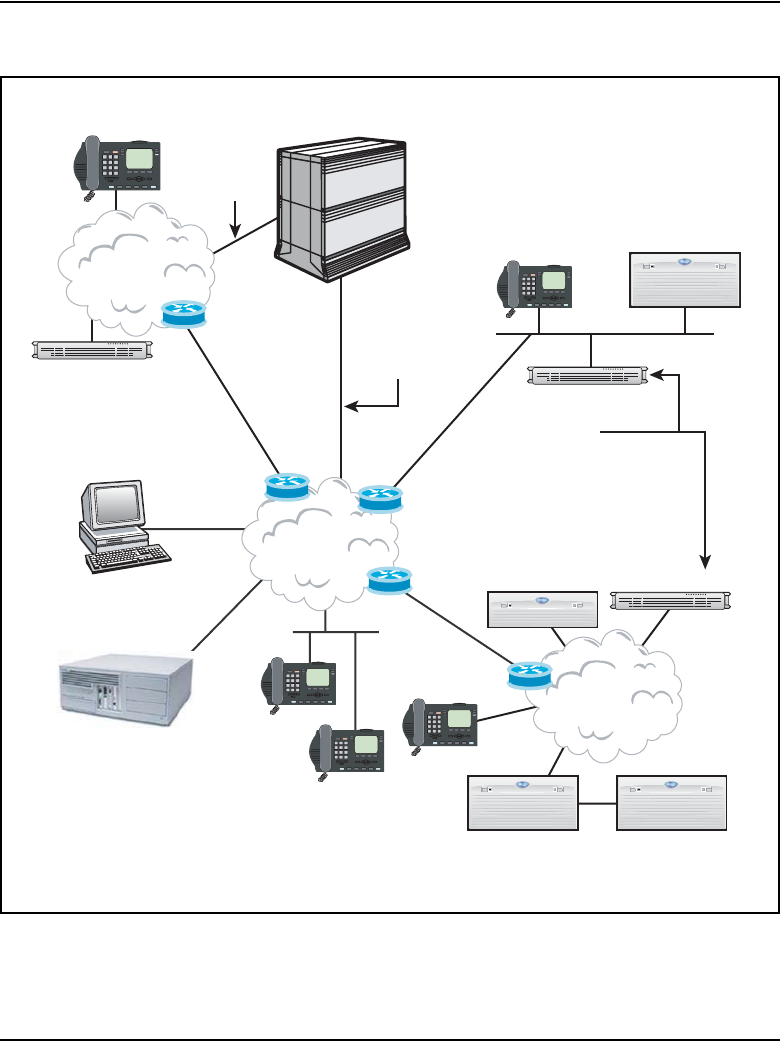
Interworking
The IP Phone uses the IP network to communicate with the Voice Gateway
Media Card and the optional DHCP server. Figure 1 on page 34 shows a
diagram of the system architecture.
Page 34 of 910 Description
553-3001-365 Standard 4.00 August 2005
Figure 1
System architecture
553-AAA0400
BCM
LAN
CS 1000
CS 1000M
WAN
Call Server Signaling Server
Media Gateway and
Media Gateway Expansion
Media streams routed
directly using IP
IP
Phones
Web Browser
for Element Manager
Requires BCM
Release 3.0 or higher
LAN
Signaling Server
IP Trunk 3.0
or later
Branch Media Gateway
Signaling Server
(Optionally Redundant)
-Terminal Proxy Server
-H.323 proxy
-Primary Gatekeeper
-Element Manager Web Server
Signaling Server
(Optionally Redundant)
-Terminal Proxy Server
-H.323 proxy
-Alternate Gatekeeper
-Element Manager Web Server
IP Line

Description Page 35 of 910
IP Line Description, Installation and Maintenance
Applicable systems
The CS 1000 and Meridian 1 systems support the Media Card 32-port line
card, Media Card 8-port line card, and ITG-Pentium 24-port line card.
Unsupported products
The following remote service products do not support the Media Card 32-port
line card, Media Card 8-port line card, and ITG-Pentium 24-port line card:
• Carrier Remote
• Mini-carrier Remote
• Fiber Remote
• Fiber Remote Multi-IPE
System requirements
CS 1000 Release 4.5 software is the minimum system software for
IP Line 4.5.
OTM 2.2 and Element Manager
Optivity Telephony Manager (OTM) 2.2 and Element Manager are used
throughout this document as the primary interface for Voice Gateway Media
Cards and IP Line 4.5.
OTM 2.2 is the minimum required version.
CS 1000 systems
Either OTM 2.2 or Element Manager can be used as the configuration,
administration, and maintenance interface for IP Line 4.5 on a CS 1000
system.
If trying to use OTM 2.2 to perform an action available through Element
Manager, then OTM 2.2 launches Element Manager automatically.
OTM 2.2 is used for configuration activities not supported by Element
Manager, such as terminal administration.

Page 36 of 910 Description
553-3001-365 Standard 4.00 August 2005
Meridian 1
OTM 2.2 is used as the configuration, administration, and maintenance
interface for IP Line 4.5 on a Meridian 1. Element Manager cannot be used,
as Element Manager is located on a Signaling Server, and there is no
Signaling Server in a Meridian 1.
Corporate Directory
OTM 2.2 is necessary for creation of the Corporate Directory database.
SNMP and alarms
Element Manager does not provide a SNMP alarm browser, so the OTM 2.2
Alarm Manager is recommended when SNMP alarm collection is required.
System configurations
Although IP Line 4.5 can be used in different system configurations and its
use can vary in those configurations, there are four basic system
configurations. See Table 2.
IP Line 4.5 can use the Signaling Server if the Signaling Server is deployed
in the system configuration.
Table 2
Possible system configurations
System Signaling Server present
1 Meridian 1 No
2 CS 1000E Yes
3 CS 1000M Yes
4 CS 1000S Yes

Description Page 37 of 910
IP Line Description, Installation and Maintenance
Meridian 1
A Meridian 1 system does not have a Signaling Server in its configuration.
Each Voice Gateway Media Card functions as both a UNIStim Line Terminal
Proxy Server (LTPS) and voice gateway.
In this system configuration, one Voice Gateway Media Card is configured
as the Leader. IP Phones register with individual Voice Gateway Media
Cards.
Note: If a Media Card 32-port card, a Media Card 8-port card, or an
ITG-P 24-port card is running IP Line 4.5 software, it is known as a
Voice Gateway Media Card.
CS 1000 systems
CS 1000 systems have a Signaling Server in their network configuration. The
Signaling Server is a server that provides signaling interfaces to the
IP network. The Signaling Server’s central processor drives the signaling for
IP Phones and IP Peer networking.
In IP Line 4.5, the LTPS executes on the Signaling Server and the voice
gateway executes on the Voice Gateway Media Cards. All IP Phones register
with the Signaling Server. The Voice Gateway Media Cards only provide
access to the voice gateway.
The Signaling Server is the node leader and, by default, acts as a Master for
the node.
Signaling Server redundancy
There are several methods of redundancy for a Signaling Serve. See Table 3.
Table 3
Methods of Signaling Server redundancy (Part 1 of 2)
Stage Description
With a backup Signaling Server
1A backup Signaling Server can be configured in a normal configuration.

Page 38 of 910 Description
553-3001-365 Standard 4.00 August 2005
Software delivery
IP Line 4.5 supports software delivery through the following formats:
1CompactFlash
2Signaling Server CD-ROM
3Download from the Nortel web site
Note: Stand-alone IP Line 4.5 software is not available through
CD-ROM.
2If the primary Signaling Server fails, the backup Signaling Server takes over and
all IP Phones register with the backup Signaling Server.
3If the backup Signaling Server fails, one of the Voice Gateway Media Cards is
elected to be the node Master.
4The IP Phones then register to the Voice Gateway Media Cards.
Without a backup Signaling Server
1If there is no backup Signaling Server, and the primary Signaling Server fails, one
of the Voice Gateway Media Cards is elected to be the node Master.
2The IP Phones then register to the Voice Gateway Media Cards.
Table 3
Methods of Signaling Server redundancy (Part 2 of 2)
Stage Description

Description Page 39 of 910
IP Line Description, Installation and Maintenance
The IP Line 4.5 software and related documentation (such as Readme First
documents) can be downloaded from the Nortel web site.
Required packages
The IP Phones require the software packages listed in Table 4.
Note: To configure IP Line 4.5 in groups 5-7 on Option 81C CP PII or
CS 1000M MG, the Fibre Network (FIBN) software package 365 is
required.
Table 4
Required packages
Package Package number
M2000 Digital Sets (DSET) 88
Aries Digital Sets (ARIE) 170

Page 40 of 910 Description
553-3001-365 Standard 4.00 August 2005
IP Line package components lists
CS 1000 and Meridian 1 package components
Table 5 lists the IP Line 4.5 package components for CS 1000 and Meridian 1
systems.
Table 5
IP Line 4.0 Media Card 32-port line card package components (Part 1 of 2)
Component Code
Media Card 32-port - IP Line 4.5 Voice Gateway Systems Package includes
the following:
• Media Card 32-port assembly NTVQ01BB
• IP Line 4.5 Voice Gateway CompactFlash NTM403AC
• ITG EMC Shielding Kit (NTVQ83AA)
• Readme First Document
• Shielded 50-pin to Serial/ELAN/TLAN adaptor
• PC Maintenance cable (NTAG81CA)
• IP Line 4.5 NTP (CD-ROM)
• ITG-specific Meridian 1 Backplane 50-pin I/O Panel Filter Connector
(NTCW84JA) (see Note)
NTDU41FC

Description Page 41 of 910
IP Line Description, Installation and Maintenance
IP Line 4.5 Voice Gateway NTP (CD-ROM), which includes:
•IP Line: Description, Installation, and Operation (553-3001-365)
•IP Phones: Description, Installation, and Operation (553-3001-368)
•IP Phone 2001 User Guide
•IP Phone 2001 Quick Reference Card
•IP Phone 2002 User Guide
• IP Phone 2002 Quick Reference Card
•IP Phone 2004 User Guide
• IP Phone 2004 Quick Reference Card
• IP Phone 2007 User Guide
• IP Phone 2007 Quick Reference Card
• IP Audio Conference Phone 2033 User Guide
• IP Audio Conference Phone 2033 Quick Reference Card
•IP Softphone 2050 User Guide
•Mobile Voice Client 2050 User Guide
NTDW81AG
Note: The I/O panel filter connector is not required for Meridian 1 Option 11C Cabinet,
Meridian 1 Option 11C Chassis, CS 1000M Cabinet, CS 1000M Chassis, or CS 1000S
systems.
Table 5
IP Line 4.0 Media Card 32-port line card package components (Part 2 of 2)
Component Code

Page 42 of 910 Description
553-3001-365 Standard 4.00 August 2005
IP Line 4.5 Media Card 8-port card
package components
Table 6 lists the IP Line 4.5 Media Card 8-port card package components. The
Media Card 8-port card is intended for branch office configurations. The card
is applicable to the CS 1000 and Meridian 1 systems.
Table 6
IP Line 4.5 Media Card 8-Port card package components
Component Code
Media Card 8-port - IP Line 4.5 Voice Gateway Systems Package includes:
• Media Card 8-port Assembly NTVQ01AB
• IP Line 4.5 CompactFlash NTM403AC
• ITG EMC Shielding Kit NTVQ83AA
• Readme First Document
• Shielded 50-pin to Serial/ELAN/TLAN adaptor
• PC Maintenance Cable NTAG81CA
• IP Line 4.0 NTP (CD-ROM) NTDW81AF
• ITG-specific Meridian 1 Backplane 50-pin I/O Panel Filter Connector
(NTCW84JA) (see Note)
NTDU41FB
Note: The I/O panel filter connector is not required for Meridian 1 Option 11C Cabinet,
Meridian 1 Option 11C Chassis, CS 1000M Cabinet, CS 1000M Chassis, or CS 1000S
systems.

Description Page 43 of 910
IP Line Description, Installation and Maintenance
Documentation
The following documents are available on the IP Line 4.5 CD-ROM and on
the Nortel web site:
•IP Line: Description, Installation, and Operation (553-3001-365)
•IP Phones: Description, Installation, and Operation (553-3001-368)
•IP Phone 2001 User Guide
•IP Phone 2001 Quick Reference Card
•IP Phone 2002 User Guide
• IP Phone 2002 Quick Reference Card
•IP Phone 2004 User Guide
• IP Phone 2004 Quick Reference Card
•IP Phone 2007 User Guide
• IP Phone 2007 Quick Reference Card
•IP Audio Conference Phone 2033 User Guide
•IP Audio Conference Phone 2033 Quick Reference Card
•IP Softphone 2050 User Guide
•Mobile Voice Client 2050 User Guide
Voice Gateway Media Cards
Voice Gateway Media Card is a term used to encompass the Media Card
32-port line card, Media Card 8-port line card, and ITG-P 24-port line card.
These cards plug into an Intelligent Peripheral Equipment (IPE) shelf in the
Meridian 1 and CS 1000M systems, into a Media Gateway 1000S and Media
Gateway 1000S Expander in the CS 1000S system, and into a Media Gateway
1000E and Media Gateway 1000E Expander in the CS 1000E system.
The ITG-P 24-port line card occupies two slots while the Media Card line
card occupies only one slot. The Media Card comes in two versions: 8-port
and 32-port.

Page 44 of 910 Description
553-3001-365 Standard 4.00 August 2005
The Media Card has the following features:
• 32-port card’s packet processing power is greater than that of the ITG-P
24-port line card
• increases the channel density from 24 to 32 ports (for 32-port version)
• reduces the slot count from a dual IPE slot to a single IPE slot
• supports up to 128 IP Phones for the 32-port version, while 32 IP Phones
are supported on the 8-port version (if a Signaling Server is not present
in the network configuration).
The 8-port version is typically intended for the Media Gateway 1000B used
with the Branch Office feature in branch office locations.
Table 7 provides a comparison of the ITG-P 24-port line card and Media Card
32-port and 8-port line cards.
Table 7
Comparison of ITG-P 24-port and Media Card 32-port and 8-port cards (Part 1 of 2)
Item
ITG-P 24-port
card
Media Card 32-port
card
Media Card 8-port
card
Total DSP Channels 24 32 8
Number of slots the card
occupies
2 1 1
Operating System VxWorks 5.3 VxWorks 5.4 VxWorks 5.4
Processor Pentium IXP1200 IXP1200
DSP 8 x TI5409 4 x TI5421 1 x TI5421
Telogy version 7.01 8.1 High Density
version
(8 ports for each
DSP)
8.1 High Density
version
(8 ports for each
DSP)
Number of IP Phones that
can register on each Voice
Gateway Media Card
96
(in a Meridian 1 –
see note)
128
(in a Meridian 1 –
see note)
32
(in a Meridian 1 –
see note)

Description Page 45 of 910
IP Line Description, Installation and Maintenance
Voice Gateway Media Cards have an ELAN network interface (10BaseT)
and a TLAN network interface (10/100BaseT) on the I/O panel.
Note: The ELAN (Embedded LAN) subnet isolates critical telephony
signaling between the Call Server and the other components. The ELAN
subnet is also known as the Management LAN subnet.
The TLAN (Telephony LAN) subnet carries telephony/voice/signaling
traffic. The TLAN subnet, also known as the Voice LAN subnet,
connects to the customer network and the PSTN.
There is an RS-232 Maintenance Port connection on the faceplates of both the
ITG-P 24-port card and the Media Card card. The ITG-P 24-port card has an
alternative connection to the same serial port on the I/O backplane.
Image file name prefixes
shown by swVersionShow
command
IPL P IPL SA IPL SA
/C: drive On board Flash 2
x 4Mb
Plug-in
CompactFlash
32 Mb
Plug-in
CompactFlash
32 Mb
Upgrade Two images files One image file
(no backup)
One image file
(no backup)
Note: If a Voice Gateway Media Card is used in a CS 1000 system, then the IP Phones
register to the Signaling Server instead of the Voice Gateway Media Card, and are not subject
to these restrictions. A Signaling Server can register a maximum of 5000 IP Phones.
CAUTION
Do not connect maintenance terminals to both the
faceplate and the I/O panel serial maintenance port
connections at the same time.
Table 7
Comparison of ITG-P 24-port and Media Card 32-port and 8-port cards (Part 2 of 2)
Item
ITG-P 24-port
card
Media Card 32-port
card
Media Card 8-port
card

Page 46 of 910 Description
553-3001-365 Standard 4.00 August 2005
Capacity
The Virtual TN (VTN) feature allows each Voice Gateway Media Card to
support more IP Phones than there are physical bearer channels. There are 24
bearer channels on each ITG-P card and 8 or 32 channels on each Media Card.
Both cards support a 4:1 concentration of registered IP Phones (IP Phones
2001, 2002, 2004, 2007, IP Audio Conference Phone 2033, IP Softphone
2050, Mobile Voice Client (MVC) 2050, WLAN Handset 2210, WLAN
Handset 2211, and WLAN Handset 2212) to gateway channels. The ITG-P
supports 96 registered IP Phones. The Media Card supports 32 registered IP
Phones (when the card has 8 channels) or 128 registered IP Phones (when the
card has 32 channels). The IP Phones require the services of the bearer
channels only when they are busy on a call that requires a TDM circuit such
as an IP Phone-to-digital telephone/trunk/voice mail/conference. When an IP
Phone is idle or there is an IP-to-IP call, no gateway channel is required.
When the total number of IP Phones that are registered or are attempting to
register reaches the limit (96 on the ITG-P, 32 or 128 on the Media Card), the
Voice Gateway Media Card recognizes this and no more IP Phones are
assigned to the card. Each Voice Gateway Media Card is restricted to a total
of 1200 call attempts per hour distributed across all the IP Phones associated
with the card.

Description Page 47 of 910
IP Line Description, Installation and Maintenance
Media Card controls, indicators, and connectors
Figure 2 shows the Media Card 32-port and 8-port card faceplate.
Figure 2
Media Card faceplate
HEX display
RS-232 maintenance port
Ethernet activity LEDs
PC Card slot (Drive /A:)
Reset button
MC Enable LED
Lock latches
J2
A:
100
10
A
E T
Reset
NTVQ01AA
553-SMC0001
MAC address label
(TLAN and ELAN network interface addresses)

Page 48 of 910 Description
553-3001-365 Standard 4.00 August 2005
Faceplate components
The components on the faceplate of the Media Card 32-port and 8-port card
are described in the following sections.
Reset button
Use the Reset button on the faceplate to manually reset the Media Card. This
enables the card to be reset without cycling power to it. The Reset button is
used to reboot the card after a software upgrade or to clear a fault condition.
Enable LED
The faceplate red LED indicates the following:
• the enabled/disabled status of the card
• the self-testing result during power up or card insertion into an
operational system
PC Card slot
This slot accepts the Type I or Type II standard PC Flash Cards, including
ATA Flash cards (3 Mb to 170 Mb). The slot is labeled /A:.
Nortel supplies PC Card adaptors that enable CompactFlash cards to be used
in the slot.
WARNING
Do not format the PC Card using a Windows application.
As well, only format the PC Card using the type of card on
which it will be running. For example, a PC Card
formatted using a Small System Controller (SSC) card is
only readable by the SSC card. It is not readable by the
ITG-P 24-port card or the Media Card. A PC Card
formatted using a Voice Gateway Media Card (ITG-P
24-port card or Media Card) is only readable by another
Voice Gateway Media Card. It is not readable by the SSC
card.

Description Page 49 of 910
IP Line Description, Installation and Maintenance
MAC address label
The MAC address label on the card’s faceplate is labeled ETHERNET
ADDRESS. It shows the TLAN and ELAN network interface MAC
addresses. The Management /ELAN network interface MAC address for each
card is assigned during manufacturing and is unchangeable. The MAC
address label on the Media Card is similar to the following example:
ETHERNET ADDRESS
TLAN
00:60:38:BD:C9:9C
ELAN
00:60:38:BD:C9:9D
Ethernet activity LEDs
The faceplate contains six Ethernet activity LEDs: three for the ELAN
network interface and three for the TLAN network interface. The LEDs
indicate the following links on the ELAN network interface and TLAN
network interface (in order from the top):
1100 (100BaseT)
210 (10BaseT)
3A (Activity)
Maintenance hex display
This is a four-digit LED-based hexadecimal display that provides the role of
the card. It also provides an indication of fault conditions and the progress of
PC Card-based software upgrades or backups.
RS-232 Maintenance Port
The Media Card faceplate provides a female 8-pin mini-DIN serial
maintenance port connection. The faceplate on the card is labeled J2.
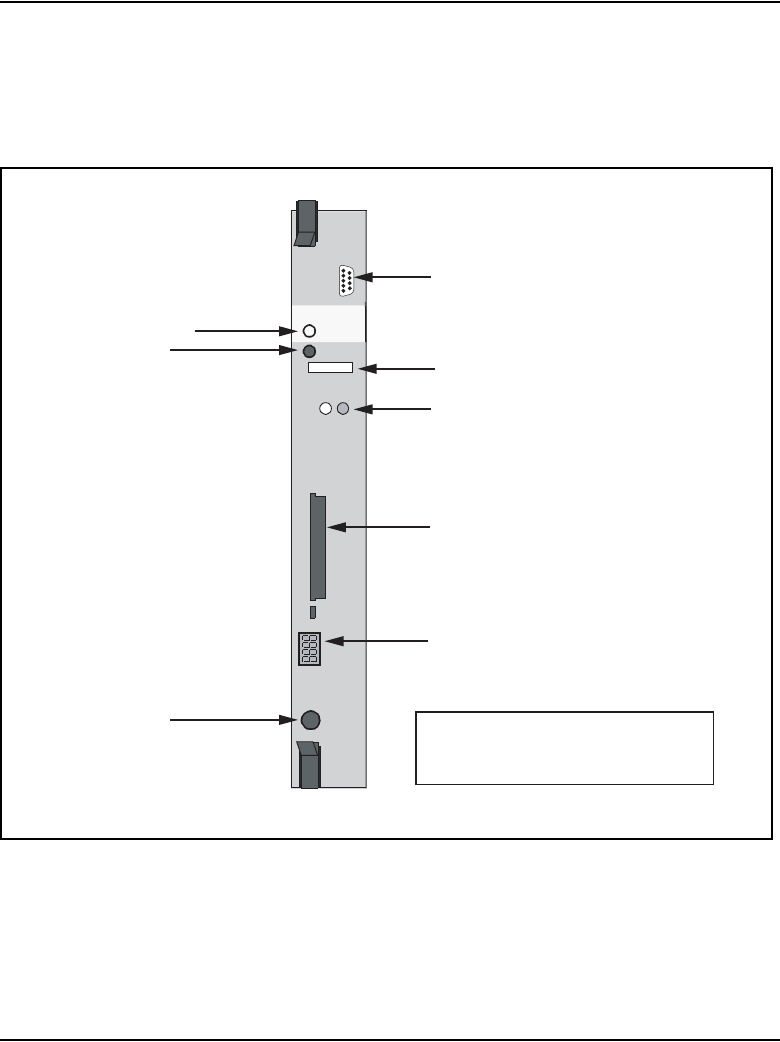
Page 50 of 910 Description
553-3001-365 Standard 4.00 August 2005
ITG-P 24-port card controls, indicators, and connectors
Figure 3 shows the ITG-P 24-port card faceplate components.
Figure 3
ITG-P 24-port card faceplate
ITG-P
NWK
NTVQ55AA
NWK
Status
Reset
Maint
Port
A:
553-9150
not used
ITG-P LED (card status)
TLAN Ethernet activity LEDs
Reset button
PC Card slot (Drive /A:)
Four-character LED-based
matrix maintenance display
RS-232
Maintenance Port Inboard:
- Type III PC Card slot (ATA Drive /B:)
- Onboard Flash Drive /C:
MAC address label
(motherboard and daughterboard addresses)
Description Page 51 of 910
IP Line Description, Installation and Maintenance
Faceplate components
The components on the faceplate of the ITG-P 24-port line card are described
in the following sections.
NWK
The faceplate connector labeled NWK is a 9-pin, sub-miniature D-type
connector. The connector is not used for the IP Line 4.0 application.
ITG-P LED (card status)
The red status faceplate LED indicates the enabled/disabled status of the
24 card ports. The LED is on (red) during the power-up or reset sequence.
The LED remains lit until the card is enabled by the system. If the LED
remains on, the self-test failed, the card is disabled, or the card rebooted.
Reset button
Press the Reset button to reset the card without having to cycle power to the
card. This button is normally used after a software upgrade to the card or to
clear a fault condition.
WARNING
The NWK connector looks like a 9-pin serial connector.
Do not connect a serial cable or any other cable to it. If a
cable is connected to the NWK connector, the TLAN
network interface is disabled.

Page 52 of 910 Description
553-3001-365 Standard 4.00 August 2005
MAC address label
The MAC address label on the card’s faceplate shows the motherboard and
daughterboard addresses. The ELAN network interface address corresponds
to the Management MAC address. The Management MAC address for each
card is assigned during manufacturing and is unchangeable. The ELAN
network interface MAC address is the MOTHERBOARD Ethernet address
found on the label. The MAC address label on the ITG-P 24-port line card is
similar to the following example:
ETHERNET ADDRESS
MOTHERBOARD
00:60:38:8c:03:d5
DAUGHTERBOARD
00:60:38:01:b3:cb
TLAN network interface activity LEDs (labeled NWK Status LEDs)
The two NWK Status LEDs display TLAN network interface activity.
• Green – the LED is on if the carrier (link pulse) is received from the
TLAN network interface switch.
• Yellow – the LED flashes when there is data activity on the TLAN
network interface. During heavy traffic, the yellow LED can stay
continuously lit.
Note: There are no Ethernet status LEDs for the ELAN network
interface.
Description Page 53 of 910
IP Line Description, Installation and Maintenance
PC Card slots
The ITG-P 24-port card has one faceplate PC Card slot (designated
Drive /A:). It is used for optional maintenance. The ITG-P 24-port card also
has one unused inboard slot (designated Drive /B:). The PC Card slots support
high-capacity PC flash memory cards.
Matrix maintenance display
A four-character, LED-based dot matrix display shows the maintenance
status fault codes and other card state information. For a list of the fault codes,
see Table 79: “ITG-P 24-port line card faceplate maintenance display codes”
on page 689 and Table 80: “Media Card faceplate maintenance display
codes” on page 691.
RS-232 maintenance port
The ITG-P 24-port line card faceplate provides a female 8-pin mini-DIN
serial maintenance port connection, labeled Maint Port. An alternative
connection to the faceplate serial maintenance port exists on the NTMF94EA
I/O panel breakout cable.
WARNING
Do not format the PC Card using a Windows application.
As well, only format the PC Card using the type of card on
which it will be running. For example, a PC Card
formatted using a Small System Controller (SSC) card is
only readable by the SSC card. It is not readable by the
ITG-P 24-port card or the Media Card. A PC Card
formatted using a Voice Gateway Media Card (ITG-P
24-port card or Media Card) is only readable by another
Voice Gateway Media Card. It is not readable by the SSC
card.
CAUTION
Do not connect maintenance terminals or modems to the
faceplate and I/O panel DB-9 male serial maintenance
port at the same time.

Page 54 of 910 Description
553-3001-365 Standard 4.00 August 2005
Backplane interfaces
The backplane provides connections to the following:
• ELAN network interface
• TLAN network interface
• alternate connection to the DS-30X serial maintenance port
• Card LAN interface connectors
DS-30X voice/signaling
The DS-30X serial maintenance port carries Pulse Code Modulation (PCM)
voice and proprietary signaling on the IPE backplane between the ITG-P
24-port card and the Intelligent Peripheral Equipment Controller (XPEC).
Card LAN
The card LAN carries card polling and initialization messages on the IPE
backplane between the ITG-P 24-port card and the Intelligent Peripheral
Equipment Controller (XPEC).
Assembly description
The ITG-P 24-port card assembly is a two-slot motherboard and
daughterboard combination. A PCI interconnect board connects the
motherboard and the DSP daughterboard. See Figure 4 on page 55.

Description Page 55 of 910
IP Line Description, Installation and Maintenance
Figure 4
ITG-P 24-port card physical assembly
Functional description of the Voice Gateway Media Cards
The Media Card and ITG-P 24-port line cards can perform two separate
functions, depending on the system in which the card is located:
1The card acts as a gateway between the circuit-switched voice network
and the IP network.
2The card acts as a Line Terminal Proxy Server (LTPS) or “virtual line
card” for the IP Phones, based on whether a Signaling Server is used in
the configuration or not.

Page 56 of 910 Description
553-3001-365 Standard 4.00 August 2005
Gateway functional description
The Gateway performs the following functions:
• registers with the system using the TN Registration messages
• accepts commands from the system to connect/disconnect audio channel
• uses Realtime Transport Protocol/Realtime Conferencing Protocol
(RTP/RTCP) protocol to transport audio between the gateway and the IP
Phone
• encodes/decodes audio from PCM to and from the IP Phone’s format
• provides echo cancellation for the speaker on IP Phones for echoes
originating in the circuit-switched voice network (not applicable to the IP
Softphone 2050 or MVC 2050 as they have no handsfree capability)
Gateway functionality on the Meridian 1
Since there is no Signaling Server, each Voice Gateway Media Card
functions as both the LTPS and Voice Gateway.
The Gateway portion of the card connects to the Meridian 1 through the
DS-30X backplane. The Gateway portion also receives call speech-path setup
and codec selection commands through the ELAN network interface. The IP
Phone connects to both the Gateway and the LTPS functions through the
TLAN network interface.
Gateway functionality on the CS 1000 systems
A Signaling Server is always present in the CS 1000 systems. The LTPS
executes on the Signaling Server and the Voice Gateway executes on the
Voice Gateway Media Cards. The Voice Gateway Media Cards only provide
the voice gateway access.
Active Master
The LTPS maintains a count of the number of IP Phones registered to the
card. Each IP Telephony node has one active Master. The active Master
broadcasts to all Voice Gateway Media Cards and requests a response if it has
room for another IP Phone.

Description Page 57 of 910
IP Line Description, Installation and Maintenance
The Election function uses a selection process to determine the node’s
Master. The Census function determines the Voice Gateway Media Cards
within an IP Telephony node.
IP Phone registration
IP Phone registration on a Meridian 1 system
Table 8 describes the maximum number of IP Phones that can be registered
to each type of line card in a Meridian 1 system.
For more information, refer to “System capacities” in Communication
Server 1000M and Meridian 1: Large System Planning and Engineering
(553-3021-120), Communication Server 1000M and Meridian 1:
Small System Planning and Engineering (553-3011-120), Communication
Server 1000S: Planning and Engineering (553-3031-120), and
Communication Server 1000E: Planning and Engineering (553-3041-120).
IP Phone registration on a CS 1000 system
On a CS 1000 system, the IP Phones register with the LTPS on the Signaling
Server. If a secondary Signaling Server exists, the IP Phone registrations are
split between the primary and secondary Signaling Servers to aid in load
balancing. In that case, the IP Phone registrations alternate between the
primary and secondary Signaling Servers.
Table 8
Maximum number of IP Phones that can register to a Voice Gateway
Media Card in a Meridian 1
Card type Maximum number
Media Card 32-port 128
Media Card 8-port 32
ITG-P 24-port 96

Page 58 of 910 Description
553-3001-365 Standard 4.00 August 2005
If the primary Signaling Server fails, the secondary Signaling Server takes
over (if it exists) and the IP Phones that were registered with the failed
Signaling Server reregister with the LTPS on the secondary Signaling Server.
If there is no secondary Signaling Server or the secondary Signaling Server
fails, the IP Phones register with the LTPS on the Voice Gateway Media
Cards.
For more information on Signaling Server failure and redundancy, see
Communication Server 1000S: Planning and Engineering (553-3031-120),
Communication Server 1000E: Planning and Engineering (553-3041-120), and
Signaling Server: Installation and Configuration (553-3001-212).
Virtual Terminal Manager
The Virtual Terminal Manager (VTM) performs the following functions:
• arbitrates application access to the IP Phones
• manages all the IP Phones between the applications and the UNIStim
messaging to the IP Phone
• maintains context-sensitive states of the IP Phone (for example, display
or lamp state)
• isolates IP Phone-specific information from the applications (for
example, the number of display lines, number of characters for each
display line, tone frequency, and cadence parameters)
Interactions with IP Phones
The following information describes the process by which an IP Phone
registers and unregisters with a Meridian 1 or CS 1000 system.
IMPORTANT!
Each Signaling Server supports the registration of up to 5000 IP
Phones.

Description Page 59 of 910
IP Line Description, Installation and Maintenance
Registration
Table 9 describes the registration process.
Unregistration
Table 10 describes the unregistration process.
Table 9
Registration process
Step Description
1The IP Phone receives the IP address of the Connect Server
(co-located with the LTPS) through either DHCP or manual
configuration.
2The IP Phone contacts the Connect Server.
3The Connect Server instructs the IP Phone to display a
message on its display screen requesting the customer’s IP
Telephony node number and TN.
4The node number and TN are entered. The Connect Server
redirects the IP Phone to the Node Master.
5The IP Phone contacts the Node Master. The Node Master
redirects the IP Phone to the LTPS.
6The IP Phone contacts the LTPS.
7If the IP Phone is valid, the LTPS registers it with the system.
Table 10
Unregistration process
Step Description
1If the LTPS detects a loss of connection with one of its
registered IP Phones, it logs the event.
2The LTPS then sends an unregister message to the system
for that IP Phone.

Page 60 of 910 Description
553-3001-365 Standard 4.00 August 2005
Signaling and messaging
The IP Line 4.5 application sends Scan and Signaling Distribution (SSD)
messages to the Call Server through the system’s ELAN subnet. When tone
service is provided, the service is signaled to the LTPS using new SSD
messages sent through the ELAN subnet.
Signaling protocols
The signaling protocol between the IP Phone and the IP Telephony node is
the Unified Networks IP Stimulus Protocol (UNIStim). The Reliable User
Datagram Protocol (RUDP) is the transport protocol.
RUDP
RUDP is used for:
• signaling between the Call Server and the Voice Gateway Media Cards
• signaling between the IP Telephony node and the IP Phones
Description
Signaling messages between the Voice Gateway Media Card and IP Phones
use RUDP. Each RUDP connection is distinguished by its IP address and port
number. RUDP is another layer on top of UDP. RUDP is proprietary to
Nortel.
The features of RUDP are as follows:
• provides reliable communication system over a network
• packages are resent if an acknowledgement message (ACK) is not
received following a time-out
• messages arrive in the correct sequence
• duplicate messages are ignored
• loss of contact detection

Description Page 61 of 910
IP Line Description, Installation and Maintenance
When a data sequence is packetized and sent from source A to receiver B,
RUDP adds a number to each packet header to indicate its order in the
sequence.
• If the packet is successfully transmitted to B, B sends back an ACK to A,
acknowledging that the packet has been received.
•If A receives no message within a configured time, it retransmits the
packet.
•If B receives a packet without having first received its predecessor, it
discards the packet and all subsequent packets, and a NAK (no
acknowledge) message which includes the number of the missed packet
is sent to A. A retransmits the missed packet and continues.
UNIStim
The Unified Network IP Stimulus protocol (UNIStim) is the single point of
contact between the various server components and the IP Phone.
UNIStim is the stimulus-based protocol used for communication between an
IP Phone and an LTPS on the Voice Gateway Media Card or Signaling
Server.
ELAN TCP transport
Although TCP is used for the signaling protocol between the Call Server and
the Voice Gateway Media Card, RUDP remains for the Keep Alive
mechanism for the link. This means RUDP messages are exchanged to
maintain the link status between the Call Server and the Voice Gateway
Media Card.
There is no change to UNIStim signaling. IP Phones continue to use the
RUDP transport protocol to communicate with the Voice Gateway Media
Card.
The TCP protocol enables messages to be bundled. Unlike the RUDP
transport that creates a separate message for every signaling message (such as
display updates or key messages), the TCP transport bundles a number of
messages and sends them as one packet.

Page 62 of 910 Description
553-3001-365 Standard 4.00 August 2005
Handshaking is added to the Call Server and IP Line software so that the TCP
functionality is automatically enabled. A software version check is performed
by the IP Line application each time before it attempts to establish a TCP link
with the CS 1000 and Meridian 1 CPUs. TCP transports messages, while
RUDP establishes and maintains the link.
If the version does not satisfy the minimum supported version, a RUDP link
is used instead to maintain the link and all signaling.
Virtual superloops, virtual TNs, and physical TNs
Virtual TNs (VTNs) enable configuration of service data for an IP Phone,
such as key layout and class of service, without requiring the IP Phone to be
dedicated (hard-wired) to a given TN on the Voice Gateway Media Card.
Calls are made between an IP Phone and circuit-switched telephone/trunks
using the full CS 1000 and Meridian 1 feature set. Digital Signal Processor
(DSP) channels are allocated dynamically for this type of call to perform the
encoding/decoding required to connect the IP Phone to the circuit-switched
network.
To create an IP Phone using VTNs, create a virtual superloop in LD 97 or in
Element Manager. To create the virtual superloop in Element Manager, click
System > Superloops in the Element Manager navigator.
• Up to 1024 VTNs can be configured on a single virtual superloop for
Large Systems, CS 1000M Cabinet and CS 1000M Chassis systems, and
CS 1000E systems
• Up to 128 VTNs can be configured on a single virtual superloop for
Meridian 1 Option 11C Cabinet and Meridian 1 Option 11C Chassis
systems, leading to support for a maximum of 640 VTNs for each of
these systems.

Description Page 63 of 910
IP Line Description, Installation and Maintenance
• Up to 1024 VTNs can be configured on a single virtual superloop for
CS 1000S systems. Table 11 describes the virtual superloop and virtual
card mapping on a CS 1000S system. Each superloop has two ranges of
cards.
Each ITG-P 24-port card provides 24 physical TNs and each Media Card
32-port card provides 32 physical TNs. The physical TNs are the gateway
channels (DSP ports).
Configure the physical TNs (IPTN) in LD 14. They appear as TIE trunks
without a Route Data Block (RDB).
Virtual TNs
Virtual TNs enable service data to be configured for an IP Phone, such as key
layout and class of service, without requiring a physical IP Phone to be
directly connected to the Call Server.
The concentration of IP Phones is made possible by dynamically allocating a
port (also referred to as a physical TN) of the Voice Gateway Media Card for
a circuit-switched- to-IP Phone call. All system speech path management is
done with physical TNs instead of virtual TNs.
The channels (ports) on the Voice Gateway Media Cards are pooled
resources.
The IP Phones (virtual TNs) are defined on virtual superloops.
Table 11
Virtual superloop/virtual card mapping for CS 1000S
SUPL Card
96 61-64 81-84
100 65-68 85-88
104 69-72 89-92
108 73-76 93-96
112 77-80 97-99

Page 64 of 910 Description
553-3001-365 Standard 4.00 August 2005
A virtual superloop is a hybrid of real and phantom superloops. Like phantom
superloops, no hardware (for example, XPEC or line card) is used to define
and enable units on a virtual superloop. As with real superloops, virtual
superloops use the time slot map to handle IP Phone (virtual TNs)- to-IP
Phone calls.
Licenses
There are two types of licenses:
• Basic IP User License for the IP Phone 2001 and IP Audio Conference
Phone 2033
• IP User License for the IP Phone 2002, IP Phone 2004, IP Phone 2007,
IP Softphone 2050, Mobile Voice Client (MVC) 2050, WLAN Handset
2210, WLAN Handset 2211, and WLAN Handset 2212
Note: If insufficient Basic IP User Licenses are available for the IP
Phone 2001 and IP Audio Conference Phone 2033, then the IP User
License can also be used for the IP Phone 2001 and IP Audio Conference
Phone 2033.
If there are no Basic IP User Licenses available for the IP Phone 2001 and IP
Audio Conference Phone 2033, and IP User Licenses are used, then an error
message is generated.
“SCH1976: Basic IP User License counter has reached its maximum
value. IP User License was used to configure <data> basic IP Phone(s)
type 2001. Action: (Recommended) Purchase additional Basic IP User
Licenses for IP Phones type 2001, instead of using higher-priced IP User
Licenses.”
Each time an IP Phone is configured, the system TN ISM counter is
decremented.
Customers must purchase one License for each IP Phone installed on CS 1000
and Meridian 1 systems. A new License uses the existing keycode to enable
the IP Phone in the system software. The default is zero.

Description Page 65 of 910
IP Line Description, Installation and Maintenance
To expand the License limits for the IP Phones, order and install a new
Meridian 1 or CS 1000 keycode. Refer to the Incremental Software
Management feature module in the Features and Services (553-3001-306)
NTP.
Note: Individual Licenses are not supported on Functional Pricing. With
Functional Pricing, Licenses are provisioned in blocks of eight.
License limits
The total number of TNs configured with Basic IP User Licenses must not
exceed 32767. The total number of TNs configured with IP User Licenses
must not exceed 32767. The total number of IP phones configured within the
system must not exceed the allowed system capacity limit controlled by
customer keycodes).
Zones
To optimize IP Line traffic bandwidth use between different locations, the
IP Line network is divided into “zones”, representing different topographical
areas of the network. All IP Phones and IP Line ports are assigned a zone
number indicating the zone to which they belong.
When a call is made, the codecs that are used vary, depending on which
zone(s) the caller and receiver are in.
By default, when a zone is created in LD 117 or in Element Manager:
• codecs are selected to optimize voice quality (BQ - Best Quality) for
connections between units in the same zone.
• codecs are selected to optimize voice quality (BQ - Best Quality) for
connections between units in different zones.
Note: Support for zones in Element Manager is accessed by clicking IP
Telephony > Zones in the Element Manager navigator.

Page 66 of 910 Description
553-3001-365 Standard 4.00 August 2005
Each zone can be configured to:
• optimize either voice quality (BQ) or bandwidth usage
(BB - Best Bandwidth) for calls between users in that zone
• optimize either voice quality or bandwidth usage within a zone and all
traffic going out of a zone
For more information about zones, refer to the following:
• Shared and Private zones (see “Private Zone configuration” on page 225)
• Zones and Virtual Trunks (see IP Trunk: Description, Installation, and
Operation (553-3001-363))
• Zones and branch office locations (see Branch Office: Installation and
Configuration (553-3001-214))
Administration
The Voice Gateway Media Card is administered using multiple management
interfaces, including the following:
• the IP Line 4.5 application GUI provided by OTM 2.2
• a Command Line Interface (CLI)
• administration and maintenance overlays of Call Servers
• a web browser interface provided by Element Manager. Element
Manager is used for administering Voice Gateway Media Cards in the
systems that use a Signaling Server
IP Line 4.5 application in OTM 2.2
For Meridian 1 systems, OTM 2.2 is required for IP Line 4.5. OTM 2.2 is
used for tasks such as the following:
• creating a node
• adding Voice Gateway Media Cards to the node
• transmitting loadware to the Voice Gateway Media Cards
• upgrading loadware

Description Page 67 of 910
IP Line Description, Installation and Maintenance
• defining SNMP alarms
• selecting codecs
Element Manager
Element Manager is a resident web-based user interface used to configure and
maintain CS 1000 components. Element Manager’s web interface enables IP
Line to be configured and managed from a web browser.
Description
Element Manager is a simple and user-friendly web-based interface that
supports a broad range of system management tasks, including:
• configuration and maintenance of IP Peer and IP Telephony features
• configuration and maintenance of traditional routes and trunks
• configuration and maintenance of numbering plans
• configuration of Call Server data blocks (such as configuration data,
customer data, Common Equipment data, D-channels)
• maintenance commands, system status inquiries, backup and restore
functions
• software download, patch download, patch activation
Element Manager has many features to help administrators manage systems
with greater efficiency. Examples are as follows:
• Web pages provide a single point-of-access to parameters that were
traditionally available through multiple overlays.
• Parameters are presented in logical groups to increase ease-of-use and
speed-of-access.
• The “hide or show information” option enables administrators to see
information that relates directly to the task at hand.
• Full-text descriptions of parameters and acronyms help administrators
reduce configuration errors.
• Configuration screens offer pre-selected defaults, drop-down lists,
checkboxes, and range values to simplify response selection.

Page 68 of 910 Description
553-3001-365 Standard 4.00 August 2005
The Element Manager web server resides on the Signaling Server and can be
accessed directly through a web browser or Optivity Telephony Manager
(OTM). The OTM navigator includes integrated links to each network system
and their respective instances of Element Manager.
Command Line Interface
Definition
The Command Line Interface (CLI) provides a text-based interface to
perform specific Signaling Server and Voice Gateway Media Card
installation, configuration, administration, and maintenance functions.
Access
Establish a CLI session by connecting a TTY or PC to the card serial port or
Telnet through the ELAN or TLAN network interface IP address.
For more information about the CLI commands, see “IP Line CLI
commands” on page 710.
Overlays
For information on the overlays, refer to Software Input/Output:
Administration (553-3001-311).
IMPORTANT!
In the case of an IP Telephony node with no Signaling Server, the CLI
must be used to configure the Leader card of the IP Telephony node.
This enables OTM 2.2 and Element Manager to communicate with the
Leader card and the node.

Page 69 of 910
IP Line Description, Installation and Maintenance
252
Features
Contents
This section contains information on the following topics:
Introduction . . . . . . . . . . . . . . . . . . . . . . . . . . . . . . . . . . . . . . . . . . . . . . 72
Active Call Failover for IP Phones . . . . . . . . . . . . . . . . . . . . . . . . . . . . 75
Minimum requirements . . . . . . . . . . . . . . . . . . . . . . . . . . . . . . . . . . 78
ACF mode . . . . . . . . . . . . . . . . . . . . . . . . . . . . . . . . . . . . . . . . . . . . 78
ACF scenarios . . . . . . . . . . . . . . . . . . . . . . . . . . . . . . . . . . . . . . . . . 79
Firmware downloads . . . . . . . . . . . . . . . . . . . . . . . . . . . . . . . . . . . . 86
WLAN Handsets 2210/2211/2212 . . . . . . . . . . . . . . . . . . . . . . . . . . 86
Operating parameters . . . . . . . . . . . . . . . . . . . . . . . . . . . . . . . . . . . . 87
Feature interactions . . . . . . . . . . . . . . . . . . . . . . . . . . . . . . . . . . . . . 90
Installation and configuration. . . . . . . . . . . . . . . . . . . . . . . . . . . . . . 97
Configurable RUDP Timeout and Retries Count. . . . . . . . . . . . . . . 97
Overlay and command modifications. . . . . . . . . . . . . . . . . . . . . . . . 99
Status definitions . . . . . . . . . . . . . . . . . . . . . . . . . . . . . . . . . . . . . . . 99
LD 32 STAT command . . . . . . . . . . . . . . . . . . . . . . . . . . . . . . . . . . 100
LD 80 TRAC command . . . . . . . . . . . . . . . . . . . . . . . . . . . . . . . . . . 101
LD 117 STIP ACF command . . . . . . . . . . . . . . . . . . . . . . . . . . . . . . 103
LD 117 STIP ACF in Element Manager . . . . . . . . . . . . . . . . . . . . . 104
isetShow command. . . . . . . . . . . . . . . . . . . . . . . . . . . . . . . . . . . . . . 106
DSP peg counter for CS 1000E systems . . . . . . . . . . . . . . . . . . . . . . . . 107
Enhanced UNIStim Firmware Download for IP Phones . . . . . . . . . . . 108
Operating parameters . . . . . . . . . . . . . . . . . . . . . . . . . . . . . . . . . . . . 109
Feature interactions . . . . . . . . . . . . . . . . . . . . . . . . . . . . . . . . . . . . . 110
System view . . . . . . . . . . . . . . . . . . . . . . . . . . . . . . . . . . . . . . . . . . . 111

Page 70 of 910 Features
553-3001-365 Standard 4.00 August 2005
Download maximums . . . . . . . . . . . . . . . . . . . . . . . . . . . . . . . . . . . 114
Immediate and delayed firmware downloads . . . . . . . . . . . . . . . . . 114
Maintenance Mode. . . . . . . . . . . . . . . . . . . . . . . . . . . . . . . . . . . . . . 116
Call Server commands . . . . . . . . . . . . . . . . . . . . . . . . . . . . . . . . . . . 119
LTPS CLI commands. . . . . . . . . . . . . . . . . . . . . . . . . . . . . . . . . . . . 126
Element Manager . . . . . . . . . . . . . . . . . . . . . . . . . . . . . . . . . . . . . . . 132
IP Phone firmware management in Element Manager . . . . . . . . . . 132
Ethernet Diagnostics in Element Manager. . . . . . . . . . . . . . . . . . . . 140
Maintenance Mode commands in Element Manager. . . . . . . . . . . . 146
Iset commands in Element Manager . . . . . . . . . . . . . . . . . . . . . . . . 149
Firmware download using UNIStim FTP. . . . . . . . . . . . . . . . . . . . . . . 150
CLI commands. . . . . . . . . . . . . . . . . . . . . . . . . . . . . . . . . . . . . . . . . 153
NAT Traversal feature . . . . . . . . . . . . . . . . . . . . . . . . . . . . . . . . . . . . . 159
Echo Servers . . . . . . . . . . . . . . . . . . . . . . . . . . . . . . . . . . . . . . . . . . 160
Mapping . . . . . . . . . . . . . . . . . . . . . . . . . . . . . . . . . . . . . . . . . . . . . . 160
NAT Mapping Keep Alive. . . . . . . . . . . . . . . . . . . . . . . . . . . . . . . . 163
Mute and Hold considerations . . . . . . . . . . . . . . . . . . . . . . . . . . . . . 164
NAT and VLANs . . . . . . . . . . . . . . . . . . . . . . . . . . . . . . . . . . . . . . . 166
NAT Traversal and Proactive Voice Quality Management . . . . . . . 168
Configuring NAT Traversal in Element Manager . . . . . . . . . . . . . . 168
Configuring NAT Traversal in LD 117 . . . . . . . . . . . . . . . . . . . . . . 169
CLI commands. . . . . . . . . . . . . . . . . . . . . . . . . . . . . . . . . . . . . . . . . 172
Personal Directory, Callers List, and Redial List . . . . . . . . . . . . . . . . . 182
IP Call Recording . . . . . . . . . . . . . . . . . . . . . . . . . . . . . . . . . . . . . . . . . 183
Enhanced IP Call Recording . . . . . . . . . . . . . . . . . . . . . . . . . . . . . . 184
Feature interactions . . . . . . . . . . . . . . . . . . . . . . . . . . . . . . . . . . . . . 186
Identifying the IP Phone . . . . . . . . . . . . . . . . . . . . . . . . . . . . . . . . . 187
Administration . . . . . . . . . . . . . . . . . . . . . . . . . . . . . . . . . . . . . . . . . 189
pbxLink connection failure detection . . . . . . . . . . . . . . . . . . . . . . . . . . 196
Displaying pbxLink information . . . . . . . . . . . . . . . . . . . . . . . . . . . 196
LD 117 STAT SERV . . . . . . . . . . . . . . . . . . . . . . . . . . . . . . . . . . . . . . 197
pbxLink information . . . . . . . . . . . . . . . . . . . . . . . . . . . . . . . . . . . . 198
Application information. . . . . . . . . . . . . . . . . . . . . . . . . . . . . . . . . . 198
IP Phone support. . . . . . . . . . . . . . . . . . . . . . . . . . . . . . . . . . . . . . . . . . 202
IP Phone Key Expansion Module . . . . . . . . . . . . . . . . . . . . . . . . . . 211

Features Page 71 of 910
IP Line Description, Installation and Maintenance
Corporate Directory. . . . . . . . . . . . . . . . . . . . . . . . . . . . . . . . . . . . . . . . 211
Element Manager support . . . . . . . . . . . . . . . . . . . . . . . . . . . . . . . . . . . 212
BOOTP and CONFIG.INI . . . . . . . . . . . . . . . . . . . . . . . . . . . . . . . . 213
Call Statistics collection . . . . . . . . . . . . . . . . . . . . . . . . . . . . . . . . . . . . 214
Counting IP Phones . . . . . . . . . . . . . . . . . . . . . . . . . . . . . . . . . . . . . 214
IP Phone Zone Traffic Report 16 . . . . . . . . . . . . . . . . . . . . . . . . . . . 220
User-defined feature key labels. . . . . . . . . . . . . . . . . . . . . . . . . . . . . . . 224
Private Zone configuration . . . . . . . . . . . . . . . . . . . . . . . . . . . . . . . . . . 225
Shared Zone . . . . . . . . . . . . . . . . . . . . . . . . . . . . . . . . . . . . . . . . . . . 226
Private Zone . . . . . . . . . . . . . . . . . . . . . . . . . . . . . . . . . . . . . . . . . . . 226
LD 117 . . . . . . . . . . . . . . . . . . . . . . . . . . . . . . . . . . . . . . . . . . . . . . . 227
Run-time configuration changes . . . . . . . . . . . . . . . . . . . . . . . . . . . . . . 229
Network wide Virtual Office. . . . . . . . . . . . . . . . . . . . . . . . . . . . . . . . . 231
Branch Office and Media Gateway 1000B . . . . . . . . . . . . . . . . . . . . . . 235
802.1Q support . . . . . . . . . . . . . . . . . . . . . . . . . . . . . . . . . . . . . . . . . . . 236
Configuration of 802.1Q on IP Phones . . . . . . . . . . . . . . . . . . . . . . 236
Control of the IP Phone’s 802.1Q . . . . . . . . . . . . . . . . . . . . . . . . . . 239
802.1Q and the Voice Gateway Media Cards . . . . . . . . . . . . . . . . . 239
Three-port switch support. . . . . . . . . . . . . . . . . . . . . . . . . . . . . . . . . 240
Data Path Capture tool . . . . . . . . . . . . . . . . . . . . . . . . . . . . . . . . . . . . . 240
IP Phone firmware. . . . . . . . . . . . . . . . . . . . . . . . . . . . . . . . . . . . . . . . . 240
Minimum firmware version . . . . . . . . . . . . . . . . . . . . . . . . . . . . . . . 240
Firmware download . . . . . . . . . . . . . . . . . . . . . . . . . . . . . . . . . . . . . 240
Meridian 1 . . . . . . . . . . . . . . . . . . . . . . . . . . . . . . . . . . . . . . . . . . . . 242
CS 1000 systems. . . . . . . . . . . . . . . . . . . . . . . . . . . . . . . . . . . . . . . . 243
Graceful Disable . . . . . . . . . . . . . . . . . . . . . . . . . . . . . . . . . . . . . . . . . . 245
Operation of the LTPS DISI. . . . . . . . . . . . . . . . . . . . . . . . . . . . . . . 246
Feature operation of the Voice Gateway DISI . . . . . . . . . . . . . . . . . 247
Hardware watchdog timer . . . . . . . . . . . . . . . . . . . . . . . . . . . . . . . . . . . 248
Codecs . . . . . . . . . . . . . . . . . . . . . . . . . . . . . . . . . . . . . . . . . . . . . . . . . . 249
Set type checking and blocking. . . . . . . . . . . . . . . . . . . . . . . . . . . . . . . 249
Enhanced Redundancy for IP Line nodes . . . . . . . . . . . . . . . . . . . . . . . 251

Page 72 of 910 Features
553-3001-365 Standard 4.00 August 2005
Introduction
Table 12 outlines the IP Line features available for CS 1000 and Meridian 1
systems with CS 1000 Release 4.5 software.
Table 12
IP Line 4.5 feature support (Part 1 of 4)
Feature Meridian 1 CS 1000M CS 1000S CS 1000E
Support for Media
Card
Ye s Ye s Ye s Ye s
Support for Element
Manager
No Ye s Ye s Ye s
Support for Signaling
Server
Ye s Ye s Ye s Ye s
Support for the
following IP Phones:
• IP Phone 2001
• IP Phone 2002
• IP Phone 2004
• IP Phone 2007
•IP Audio
Conference Phone
2033
• WLAN Handset
2210
• WLAN Handset
2211
• WLAN Handset
2212
Ye s Ye s Ye s Ye s
a. Node level patching is not provided by OTM 2.2. The patching CLI command of the Media Card 32-port
line card, Media Card 8-port line card, and ITG-Pentium 24-port line card can be used.
* introduced in IP Line 4.5

Features Page 73 of 910
IP Line Description, Installation and Maintenance
Support for the
following software
clients:
• IP Softphone 2050
• Mobile Voice Client
(MVC) 2050
Ye s Ye s Ye s Ye s
Support for the IP
Phone Key Expansion
Module (KEM)
Ye s Ye s Ye s
Active Call Failover *Ye s Ye s Ye s Ye s
DSP peg counter for
the CS 1000E *
No No No Ye s
Enhanced UNIStim
firmware downloads for
IP Phones *
No Ye s Ye s Ye s
Support for external
server applications
Ye s Ye s Ye s Ye s
Enhanced VLAN
support on Phase II IP
Phones; support for
Voice VLAN hardware
filter providing
enhanced traffic
control on IP Phone
and PC port
Ye s Ye s Ye s Ye s
Table 12
IP Line 4.5 feature support (Part 2 of 4)
Feature Meridian 1 CS 1000M CS 1000S CS 1000E
a. Node level patching is not provided by OTM 2.2. The patching CLI command of the Media Card 32-port
line card, Media Card 8-port line card, and ITG-Pentium 24-port line card can be used.
* introduced in IP Line 4.5

Page 74 of 910 Features
553-3001-365 Standard 4.00 August 2005
Network Address
Translation (NAT)
Tra ve rs al
No Ye s Ye s Ye s
Personal Directory,
Callers List, and Redial
List with password
protection
No Ye s Ye s Ye s
UNIStim File Transfer
Protocol (UFTP) for IP
Phone firmware
downloads
Ye s Ye s Ye s Ye s
IP Call Recording Ye s Ye s Ye s Ye s
pbxLink connection
failure detection
Ye s Ye s Ye s Ye s
Dynamic Loss Plan Ye s Ye s Ye s Ye s
Network-wide Virtual
Office
Ye s Ye s Ye s Ye s
Patching Partial Partial Ye s Ye s
802.1Q support Ye s Ye s Ye s Ye s
Corporate Directory Ye s Ye s Ye s Ye s
Data Path Capture tool Ye s Ye s Ye s Ye s
User-defined Feature
Key Labels
Ye s Ye s Ye s Ye s
Private Zone Ye s Ye s Ye s Ye s
Table 12
IP Line 4.5 feature support (Part 3 of 4)
Feature Meridian 1 CS 1000M CS 1000S CS 1000E
a. Node level patching is not provided by OTM 2.2. The patching CLI command of the Media Card 32-port
line card, Media Card 8-port line card, and ITG-Pentium 24-port line card can be used.
* introduced in IP Line 4.5

Features Page 75 of 910
IP Line Description, Installation and Maintenance
Active Call Failover for IP Phones
CS 1000 Release 4.5 introduces the Active Call Failover (ACF) feature for IP
Phones.
Graceful TPS Disable Ye s Ye s Ye s Ye s
Run-time download Ye s Ye s Ye s Ye s
Watchdog Timer Ye s Ye s Ye s Ye s
Password Guessing
Protection
Ye s Ye s Ye s Ye s
Ringer and buzzer
volume adjustment
Ye s Ye s Ye s Ye s
Set-based installation Yes (Small
Systems
only)
Yes (Small
Systems
only)
Ye s Ye s
Maintenance Audit
enhancement
Ye s Ye s Ye s Ye s
Multi-language support Ye s Ye s Ye s Ye s
Enhanced
Redundancy for IP
Line nodes
Ye s Ye s Ye s Ye s
IP Softphone 2050
user-selectable codec
(not applicable to MVC
2050 as it only
supports G.711 codec)
Ye s Ye s Ye s Ye s
Table 12
IP Line 4.5 feature support (Part 4 of 4)
Feature Meridian 1 CS 1000M CS 1000S CS 1000E
a. Node level patching is not provided by OTM 2.2. The patching CLI command of the Media Card 32-port
line card, Media Card 8-port line card, and ITG-Pentium 24-port line card can be used.
* introduced in IP Line 4.5

Page 76 of 910 Features
553-3001-365 Standard 4.00 August 2005
The ACF feature for IP Phones allows active IP calls to survive the following
failures:
• IP/IP calls and IP/TDM calls survive signaling path TLAN subnet
failures.
Note: IP/IP calls means both parties are IP Phones. IP/TDM calls means
one party is an IP Phone and the other party is a TDM telephone or trunk.
• IP and IP/TDM calls survive Signaling Server restarts.
Note: The IP/TDM call does not survive if the Voice Gateway Media
Card with the DSP resource used for the call fails.
• IP and IP/TDM calls survive LTPS ELAN subnet failures.
• IP calls survive a Call Server cold start and Call Server failures in system
configurations with a redundant Call Server of the following types (see
Note 1 on page 77):
— CS 1000S systems with an alternate Call Server when the primary
Call Server fails
— Media Gateway 1000B for a branch office configuration
— Geographic Redundancy Secondary Call Server. The feature
addresses the Primary Call Server failures.

Features Page 77 of 910
IP Line Description, Installation and Maintenance
Note 1: IP Phone to IP Phone calls survive the Call Server failures listed
above.
IP Phone to Media Gateway calls that are connected to media services
and switched-circuit line and trunk terminals are dropped on the TDM
side of the Media Gateway when the CS 1000S Alternate Call Server
performs a cold restart in order to come into service upon failure of the
Primary Call Server, and dropped again when the Primary Call Server
comes back into service.
IP Phone to Media Gateway calls through IP Peer virtual trunk routes are
preserved on the TDM side of the Media Gateway, in some cases, when
the IP Phone is redirected in ACF mode from the main office CS 1000 to
the MG 1000B at the branch office location, or from the Geographic
Redundancy Primary to the Secondary Call Server.
IP Phone to Media Gateway calls are preserved if the Media Gateway to
which the call is established is not affected by the failure, or if there is
cold restart of the Call Server that controls the Media Gateway where the
IP Peer virtual trunk call is established.
• For Call Server call processor types CP PII and CP PIV:
— IP/IP calls survive a cold start on all systems.
— IP/IP and IP/TDM calls survive a warm start on all systems.
— Graceful switchover and graceful failover to the redundant Logical
Call Processor (LCP) side of the Call Server makes the failure
transparent and allows all the calls to survive without any loss.
When the IP Phone with an active call reregisters, the call data is rebuilt if the
Call Server does not know about the call, using the internal IP Phone
information.
The ACF feature for IP Phones meets Joint Interoperability Test Command
(JITC) requirements if the LAN/WAN network is engineered to provide full
redundancy: that is, if a LAN/WAN network component fails, an alternate
path between the clients and LTPS server is provided.

Page 78 of 910 Features
553-3001-365 Standard 4.00 August 2005
Minimum requirements
The ACF feature for IP Phones has the following minimum requirements:
• Call Server must be running CS 1000 Release 4.5 software.
• LTPS must be running IP Line 4.5 software.
• IP Phones (including IP Softphone 2050) must support Unistim version
2.9. (Use the isetShow command to determine the Unistim version. One
of the columns in the isetShow output is UNIStimVsn.)
ACF mode
The ACF feature for IP Phones enables an IP Phone to reregister in the ACF
mode during a supported system failure.
The ACF mode preserves the following:
• active media session
• LED states of the Mute, Handsfree, and Headset keys
• DRAM content
Note: All other elements (the feature keys, soft keys and text areas) are
retained until the user presses a key or the connection with the Call
Server is resumed. If the user presses a key during the failover, the
display is cleared and a localized “Server Unreachable” message is
displayed.
The IP Phone uses this new mode of re-registration only when the Call Server
explicitly tells the IP Phone to do so. IP Phones clear all call information if
they register to a Call Server or LTPS that does not support the ACF feature.
IP Phone ACF timer
It is possible that there may be an LTPS supporting the ACF feature and an
LTPS that does not support the feature in the same system.
A situation could exist where it takes a long time to fix a failure and no
failover Call Server is available. During this time, the user may have released
the call by pressing the Release key or hanging up the telephone. In this case,

Features Page 79 of 910
IP Line Description, Installation and Maintenance
the call-associated resources are not used, but they still exist on the Call
Server since they are not released. To prevent this, the ten-minute Call Server
ACF timer is introduced for each call. The timer prevents call
processing-related resources from being unnecessarily used when an IP
Phone that had an active call unregisters and never reregisters.
The timer is set if:
• the ACF call status is UNREGISTERED; that is, when both parties go
offline.
• only one of the parties is offline, and the other party does not support
disconnect supervision.
ACF scenarios
Table 13 describes ACF behavior in different scenarios.
Table 13
ACF behaviors (Part 1 of 8)
Scenario Result
TLAN subnet failure:
• A call is established between IP Phones A
and B registered with the same node.
• TLAN subnet goes down.
• The IP Phones detect the connection is
lost and periodically try to reregister.
• The TLAN subnet is up shortly (less than
10 minutes), or an election is called and
another accessible LTPS node acquires
the node IP address. The IP Phones
reregister with the node again.
The call is not lost as the IP Phones
reregister.
In this scenario, the call exists on the Call
Server during the failover time and has the
following transitions:
UNREGISTERED ->HALF-REGISTERED ->
NO ACF

Page 80 of 910 Features
553-3001-365 Standard 4.00 August 2005
Signaling Server/Voice Gateway Media
Card platform failure:
• A call is established between IP Phones A
and B registered with the same node.
• The LTPS node goes down.
• The IP Phones detect the connection is
lost and periodically try to reregister.
• The LTPS node is up shortly (less than 10
minutes), or an election is called and
another accessible LTPS node acquires
the node IP address. The IP Phones
reregister with the node again.
The call is not lost as the IP Phones
reregister.
The scenario is similar to the TLAN subnet
failure, but the ACF call transition on the Call
Server is instantaneous, since Offline events
are generated in a group as the ELAN subnet
goes down.
Call Server warm restart:
• A call is established between IP Phones A
and B registered with the same Call
Server.
• The Call Server warm restart (INI) occurs.
• The users of IP Phones A and B do not go
on-hook or press any keys during the Call
Server restart.
The call is not lost.
The call is rebuilt after the warm restart and
has the following transitions:
UNREGISTED->HALF REGISTERED->NO
ACF.
The transition is almost instantaneous since
the Online messages are sent in a group as a
response to the Sync Request.
Table 13
ACF behaviors (Part 2 of 8)
Scenario Result

Features Page 81 of 910
IP Line Description, Installation and Maintenance
Call Server cold restart:
• A call is established between IP Phones A
and B registered with the same Call
Server.
• The Call Server cold restart (SYSLOAD)
occurs.
• The users of IP Phones A and B do not go
on-hook or press any keys during the Call
Server warm restart.
The call is not lost.
The call cannot be rebuilt after the SYSLOAD.
The PARTIAL REBUILT -> REBUILT
transition is almost instant since the Online
messages are sent in a group as a response
to the Sync Request.
Main office failure for branch office
(scenario 1):
• Branch IP Phones A and B register with the
Media Gateway 1000B and are re-directed
to the main office.
• IP Phones A and B registered with the
main office establish a call.
• A serious main office failure occurs. The
active Branch IP Phones cannot reregister
with the main office and reregister with the
branch office in local mode. IP Phone A
reregisters in local mode first.
The call is not lost.
The HALF REBUILT -> REBUILT transition
occurs since the far end is known to the Call
Server gateway to the Media Gateway 1000B.
Table 13
ACF behaviors (Part 3 of 8)
Scenario Result

Page 82 of 910 Features
553-3001-365 Standard 4.00 August 2005
Main office failure for branch office
(scenario 2):
• IP Phones A and B register with the Media
Gateway 1000B and are redirected to the
main office.
• Branch office warm or cold starts.
• Branch users A and B registered with the
main office establish a call.
• A serious main office failure occurs so the
active branch IP Phones cannot reregister
with the main office and they reregister
with the Branch office in local mode. IP
Phone A reregisters in local mode first.
The call is not lost.
Although the branch office LTPS wrote the IP
Phones A and B data to its RLM table when it
redirected the IP Phones to the main office,
the RLM data is lost and cannot be restored
when the branch office restarts. The transition
is similar to a Call Server cold start: PARTIAL
REBUILT -> REBUILT.
Primary Call Server failure (WAN
geographically redundant system):
• A call is established between IP Phones A
and B that are registered with the primary
site in the geographically redundant
system.
• The primary site fails.
• The IP Phones are reregistered with the
secondary site. IP Phone A reregisters
first.
The call is not lost.
IP Phones can be configured in 2 ways:
1Site 1 is the secondary site and Site 2 is
not configured.
In this case the scenario is the same as
main office failure for branch office
(scenario 1): the HALF REBUILT->
REBUILT transition.
2IP Phones have Site 1 defined as the
primary site while Site 2 is defined as the
secondary site. Registration by Site 1
fails.
In this case, the secondary site’s Call
Server does not have the RLM entries for
the reregistering IP Phones and the
scenario is the same as main office failure
for branch office (scenario 2): the
PARTIAL REBUILT -> REBUILT
transition.
Table 13
ACF behaviors (Part 4 of 8)
Scenario Result

Features Page 83 of 910
IP Line Description, Installation and Maintenance
Virtual Office login failure (scenario 1):
• IP Phone A logs into IP Phone C and
establishes a call with IP Phone B. All three
IP Phones are registered with the same
Call Server.
• TLAN subnet failure occurs. IP Phone A
goes offline first, then IP Phone B.
• Active IP Phones A and B reregister with
the system when the TLAN subnet comes
back up. IP Phone A reregisters first and
then IP Phone B.
The call is not lost.
The following ACF transitions occur:
NO ACF -> PARTIAL REBUILT -> IDLE ->
HALF REBUILT -> REBUILT
Virtual Office login failure (scenario 2):
• IP Phone A logs into IP Phone C and
establishes a call with IP Phone B. All three
IP Phones are registered with the same
Call Server.
• TLAN subnet failure occurs. IP Phone B
goes offline first, then IP Phone A.
• Active IP Phones A and B reregister with
the system when the TLAN comes back
up. IP Phone A reregisters first and then IP
Phone B.
The call is not lost.
The following ACF transitions occur:
NO ACF -> HALF REGISTERED -> IDLE ->
HALF REBUILT -> REBUILT
Table 13
ACF behaviors (Part 5 of 8)
Scenario Result

Page 84 of 910 Features
553-3001-365 Standard 4.00 August 2005
Virtual Office login failure (scenario 3):
• IP Phone A logs into IP Phone C and
establishes a call with IP Phone B. All three
IP Phones are registered with the same
Call Server.
• TLAN subnet failure occurs. IP Phones A
and B fail and IP Phone C does not fail.
• IP Phone C tries to log into its home TN
before IP Phones A and B go offline.
IP Phone C cannot log into its home TN if
another active IP Phone is logged on its TN.
IP Phone C can log into its home TN only
when the call register is released or becomes
PARTIAL REBUILT.
Refer to Virtual Office login failure scenarios 1
and 2 on page 83.
Network-wide operation — network TLAN
subnet failure:
• IP Phone A has an IP Peer call with a
remote user over a virtual trunk.
• IP Phone A’s TLAN subnet connection
fails.
• Active IP Phone A reregisters with the Call
Server when the TLAN subnet comes back
up.
The call is not lost.
The scenario is the same as if the far end
were a local IP Phone. See “TLAN subnet
failure:” on page 79.
Network-wide operation —
network Call Server warm start
• IP Phone A has an IP Peer call with a
remote user over a virtual trunk.
• The Call Server warm starts.
• Active IP Phone A reregisters with the Call
Server as the TLAN subnet comes back
up.
The call is not lost.
The scenario is the same as if the far end
were a local IP Phone. See “Call Server warm
restart:” on page 80.
Table 13
ACF behaviors (Part 6 of 8)
Scenario Result

Features Page 85 of 910
IP Line Description, Installation and Maintenance
Network-wide operation — network Call
Server cold start:
• IP Phone A has an IP Peer call with a
remote user over a virtual trunk.
• The Call Server cold starts.
• Active IP Phone A reregisters with the Call
Server as the TLAN subnet comes back
up.
The call is lost as the Call Server comes up.
Network-wide operation — network branch
office:
• Branch IP Phones A and B belong to
different branches – Branch A and Branch
B respectively. IP Phones A and B are
registered on the main office Call Server.
• A call is established between IP Phones A
and B.
• Main office Call Server failure occurs and
IP Phones A and B register with their
branches in local mode.
The call is not lost.
The scenario for each branch is the same as
the first 3 steps of “Main office failure for
branch office (scenario 2):” on page 82.
Branch A does not know about IP Phone B
and Branch B does not know about IP Phone
A. Therefore, each branch builds the
PARTIAL REBUILT call.
Two local PARTIAL REBUILT calls exist on
the branches as the IP Phones reregister in
local mode. The calls are never transitioned to
the REBUILT state and exist until the IP
Phones release the call.
IP/TDM call with TLAN subnet failure:
• IP Phone A has a call with a TDM
telephone or trunk B.
• IP Phone A’s TLAN subnet connection
fails.
• Active IP Phone A reregisters with the Call
Server as the TLAN subnet comes back
up.
The call is not lost.
The scenario is the same as “TLAN subnet
failure:” on page 79 and “Network-wide
operation — network TLAN subnet failure:” on
page 84. The call has the following transitions:
NO ACF -> HALF REGISTERED ->
UNREGISTERED.
Table 13
ACF behaviors (Part 7 of 8)
Scenario Result

Page 86 of 910 Features
553-3001-365 Standard 4.00 August 2005
Firmware downloads
If the IP Phone has an active media stream, the LTPS does not request the
firmware download in order to avoid resetting the IP Phone and losing the
call. Therefore, it is possible that a system might have IP Phones with a
mixture of firmware versions registered with it. The firmware can be
downloaded later when the idle IP Phone registers again or can be
downloaded manually using appropriate CLI commands.
WLAN Handsets 2210/2211/2212
The Wireless LAN (WLAN) Handsets 2210/2211/2212 support Active Call
Failover in the same manner as Phase 2 IP Phones if their firmware supports
UNIStim 2.9.
Network-wide operation — network Call
Server warm start:
• IP Phone A has an IP Peer call with a
remote user over a virtual trunk.
• The Call Server warm starts.
• Active IP Phone A reregisters with the Call
Server as the TLAN subnet comes back
up.
The call is not lost.
The scenario is same as if the far end were a
local IP Phone. See “Call Server warm
restart:” on page 80.
Network-wide operation — network Call
Server cold star:
• IP Phone A has an IP Peer call with a
remote user over a virtual trunk.
• The Call Server cold starts.
• Active IP Phone A reregisters with the
server as the TLAN subnet comes back up.
The call is lost as the Call Server comes back
up.
Table 13
ACF behaviors (Part 8 of 8)
Scenario Result

Features Page 87 of 910
IP Line Description, Installation and Maintenance
Operating parameters
IP Peer calls
IP Peer calls survive the following failure types:
• TLAN subnet failures.
• Signaling Server platform failures/restarts.
When the Signaling Server reboots after the failure, all sessions are lost.
Therefore, when the local IP Phone or far-end telephone releases the call,
no RELEASE message is sent to the other party. The other party must go
on-hook to become idle.
• Call Server warm starts.
IP Peer calls do not survive the Call Server cold start; all virtual trunks are
idled as the Call Server comes back up after the cold start. In this case, the
local IP Phone must go on-hook to become idle.
IP/TDM calls
IP/TDM calls do not survive a Call Server cold start; all DSP channels are
closed as the Call Server comes back up after the cold start. In this case, the
local IP Phone must go on-hook to become idle.
Dialing state
Only established calls survive failures. All calls having the DIALING state
on the Call Server are released when an LTPS or signaling failure occurs that
causes an IP Phone to unregister.
Calls that are ringing are handled as follows:
• If the IP Phone originating the ringing call unregisters, the call is released
by the Call Server.
• If the IP Phone receiving the call unregisters, the call receives CFNA
treatment if possible.

Page 88 of 910 Features
553-3001-365 Standard 4.00 August 2005
Held calls
From the ACF feature perspective, held calls are considered to be established.
This means that the call is preserved on the Call Server despite TLAN subnet
or LTPS failure. The IP Phone itself is unaware of the state of any held call.
Phase 0/1 IP Phones
Phase 0/1 phones do not support ACF.
Feature key labels
If user-defined feature key labels have been changed but no datadump has
been performed, the changes are lost if there is a Call Server failure.
SIP telephones
SIP telephones appear as IP Peer endpoints to the system. See “IP Peer calls”
on page 87.
NAT devices
The ACF feature cannot handle the case of a NAT device changing the media
path’s mapping between the IP Phone's private address and public address
during the failover period. There is no way to discover the mapping while the
port is in use. For instance, if a main office failure occurs and the user
reregisters in local mode, NAT mapping is changed and the active call cannot
survive.
Control messages
The LTPS sends the Audio Stream Control and LEDs Control commands in
separate messages. If a failure occurs in the time between the two messages,
the Audio Stream and LEDs states may not be synchronized. For example, it
is possible for the Audio Stream to be muted and a network failure to occur
at just the right moment to prevent the LED Control message for the mute
LED from being received by the IP Phone.
Held Calls
When an idle IP Phone (one without an active speech path) reregisters, a
firmware download may occur if needed. If that IP Phone actually had calls

Features Page 89 of 910
IP Line Description, Installation and Maintenance
on hold, this means the held calls cannot be retrieved until after the firmware
download is finished.
Voice Gateway Media Cards
The ACF feature does not handle failures of the Voice Gateway functionality
of the Voice Gateway Media Cards.
ELAN and TLAN subnet failures that affect the signaling with the IP Phones
registered to a Voice Gateway Media Card are addressed in the same manner
as failures affecting the Signaling Server. However, if there is a failure
affecting the speech path to an IP Phone, such as when a PBX link failure
occurs and the 10-minute PBX link timer expires, the Voice Gateway calls are
released.
Codecs
Not all the codec properties are restored for the failed-over call. The
following default codec properties are used for the active failover call:
• VAD is OFF
• G.723 Working Rate is 5.3 kbps
• G.729 Annex is Annex A
QoS monitoring
The QoS monitoring is always disabled for the failover call. This is only for
the period of the failover call; for all subsequent calls, the QoS monitoring
works as configured.
Virtual Office
Active Call Failover is not supported for the active call from an IP Phone
logged on another IP Phone to a TDM resource or virtual trunk. Such a call is
released when the LTPS detects that the connection to the IP Phone is lost.
For example, IP Phone A is logged on to IP Phone B and talking to a TDM
resource or a virtual trunk. If a TLAN subnet failure occurs and IP Phone A
reregisters with its home TN, the active call is released as IP Phone A
reregisters.

Page 90 of 910 Features
553-3001-365 Standard 4.00 August 2005
Handsfree
Scenario: IP Phone A has handsfree denied and IP Phone B has handsfree
allowed. IP Phone A is logged on IP Phone B and talks to IP Phone C using
handsfree.
If a TLAN subnet failure occurs and IP Phone A reregisters with its home TN
(with handsfree disabled), the handsfree functionality is turned off and IP
Phone A must go off-hook to continue the conversation.
ELAN subnet failure
The ACF state cannot be determined on the LTPS side during an ELAN
subnet failure. This is because the ACF state is stored on the Call Server and
it is not possible to send the ACF state on the LTPS side when the ELAN
subnet has failed.
When the ELAN subnet is down, the isetShow command always outputs the
ACF state as UNKNOWN for all established calls (the state is shown as
busy-UNK).
Feature interactions
Virtual Office and Branch Office
Branch Office
When the first failed IP Phone reregisters in local mode, the branch office
Call Server look ups the far-end branch IP Phone local TN using the specified
far-end IP address and builds a local call.
The call can be rebuilt only if both the IP Phones are branch users of the same
branch office.
Example: A regular main office IP Phone talks to the branch IP Phone
registered with the main office. A failure occurs on the main office, so that
the branch IP Phone cannot register in normal mode again, and reregisters in
local mode. Even if the main office IP Phone survives the failure, the call
cannot be rebuilt because the call becomes an IP Peer call between the branch
office and main office. This call becomes Partial Rebuilt and exists until
released.

Features Page 91 of 910
IP Line Description, Installation and Maintenance
Virtual Office
It is possible that active IP Phone A, that was logged into IP Phone B before
the failure, cannot reregister with the Call Server, because IP Phone C
performed a Virtual Office login and uses IP Phone A’s TN. In this case, the
Signaling Server/Voice Gateway Media Card locally handles the Release,
Onhook and Mute events coming from IP Phone A in the Logged Out state.
Survivable Remote Gateway
The Survivable Remote Gateway (SRG) 1.0 and SRG50 do not support ACF.
If the IP Phone is an SRG user, the active call, either in normal mode or local
mode, does not survive a failure.
NAT
The NAT discovery is delayed for an IP Phone with an active call when it
reregisters. NAT discovery messages are sent through the port used for the
RTP stream. NAT discovery is not initiated if the LTPS detects that the IP
Phone has an active RTP stream.
Personal Directory, Callers List, Redial List
The display content is cleared and the Personal Directory/Callers List/Redial
List applications are reset when the active call failover process starts. The
applications can be used again only after the IP Phone reregisters. A user that
is using one of the Personal Directory/Callers List/Redial List menus sees the
display clear and loses any data in that transaction that was not selected or
saved with the Personal Directory/Callers List/Redial List feature.
ACF implementation does not maintain data present only on the Signaling
Server/Voice Gateway Media Card. Transient data (for example, the Services
key sub-menu the user is currently in) is lost when the failover occurs and the
IP Phone reregisters.
Converged Desktop
If the Call Server maintains the active call information during the active call
failover, and the SIP Gateway maintains the link and information with the
MCS 5100 (the SIP Gateway has not failed or is not on the Signaling Server
that reboots if that is the failure mode), then a Converged Desktop call is
maintained when the involved IP Phone reregisters to the system. If the Call

Page 92 of 910 Features
553-3001-365 Standard 4.00 August 2005
Server loses the call’s information or the SIP Gateway’s Signaling Server
reboots, the Converged Desktop call is impacted.
Note: A Converged Desktop consists of a telephone and multimedia
PC Client (PCC) software.
The following are scenario examples.
Example 1: The IP Phone’s TLAN subnet fails and the IP Phone reregisters
with the same or a different TPS.
In this case, both the voice and multimedia sessions survive: if a SIP call is
established with the other party in the SIP domain, the call is not released as
the IP Phone reregisters. The multimedia applications still work: the presence
is updated on PCC after the telephone reregisters.
If the unregistered converged IP Phone releases the call during the TLAN
subnet failure, then the Presence status is updated on PCC as the idle
converged IP Phone reregisters.
Example 2: The IP Phone’s Signaling Server fails and the IP Phone
reregisters with the same or a different TPS (active converged IP Phone and
SIP Gateway are on different Signaling Servers in the same node).
In this case, both the voice and multimedia sessions survive; the scenario is
the same as the TLAN subnet failure in Example 1.
Example 3: The IP Phone’s ELAN subnet fails and the IP Phone reregisters
with the same or a different TPS.
The voice session survives. If the ELAN subnet comes back up before the
IP Phone changes the call state (that is, releases the call), then the multimedia
session is not impacted.
If the IP Phone releases the call when the ELAN subnet is still down, the PCC
status update happens when the idle converged IP Phone reregisters with the
system.
If the call is released by the supervisory timer, the status is updated on PCC
after the ELAN subnet comes back up and the Converged Desktop’s AML

Features Page 93 of 910
IP Line Description, Installation and Maintenance
ELAN subnet link is enabled (the CSA104 message is output on the Call
Server when this happens).
Example 4: Call Server warm start.
The voice and multimedia sessions survive. The Presence status is updated on
PCC as the converged IP Phone releases the call after the warm start.
Example 5: Call Server cold start.
The voice and multimedia sessions are closed as the Call Server comes up.
The Presence status becomes “Connected - Idle” even if the call is rebuilt and
active after the Call Server cold start.
IP Phone firmware downloads
The firmware is not downloaded to an IP Phone that has an active RTP stream
open when it registers with the failover system. The firmware is downloaded
later when the idle IP Phone registers again or by using appropriate CLI
commands.
IP Phone as ACD agent or supervisor telephone
If an IP Phone is used as an ACD agent (or supervisor) and the Call Server
fails, then:
• In the case of a Call Server warm start (INI), the active calls are retained
on the agent telephone.
• In the case of a Call Server cold start (SYSLOAD), the active calls are
dropped and the agents are logged out.
This applies to both the In-calls (PRIMARY) key and any secondary DN key
on the ACD telephone.
TPS failures do not impact general ACD functionality, since it is
implemented on the Call Server.
CS 1000 base features
No feature works when the active IP Phone is disconnected and trying to
reregister with the Call Server. All the features can be used in the context of

Page 94 of 910 Features
553-3001-365 Standard 4.00 August 2005
the failover call after the IP Phone reregisters (if it is not a PARTIAL
REBUILT call).
The feature context is lost on the Call Server if the Call Server fails.
The feature context is not lost on the Call Server in a case of TLAN/ELAN
subnet failure. Only the feature data on the IP Phone’s display is lost.
Feature context in Call Server failures
The context of any feature is lost on the Call Server in cases of Call Server
failure (Call Server warm or cold start). The LTPS IP Phone display is lost as
the IP Phone reregisters. This means if a feature is activated and the Call
Server fails, all the user input and data is lost.
Example: IP Phone A is in a call; the user presses the Transfer key and starts
dialing a DN. The Call Server cold or warm starts. Therefore, IP Phone A
does not accept the user input and tries to reregister with the Call Server.
When the Call Server comes back up and the IP Phones reregister, IP Phone
A does not have the Call Transfer activated. The held call is also lost: it is not
rebuilt after INI or by the ACF feature, since the call is not active.
TLAN/ELAN subnet and LTPS failures
When a network or Signaling Server/Voice Gateway Media Card failure
occurs and the active IP Phone has some feature activated, the feature context
and data is not lost on the Call Server. The user can proceed with the feature
after the IP Phone reregisters. Only the LTPS display is lost when the IP
Phone reregisters.
Example: IP Phone A is in a call; the user presses the Transfer key, and starts
dialing a DN. A TLAN subnet failure occurs when the first digit is dialed. The
user is unaware of the failure and continues dialing the DN. The digits dialed
after the failure are ignored, the IP Phone detects the failure, clears the
display, and tries to reregister with the server.
The TLAN comes up again and the IP Phone reregisters. Although the IP
Phone is now idle and the display is cleared, the IP Phone can resume dialing
the DN starting from the second digit. The IP Phone can also return to the held
call by pressing the held call’s DN key.

Features Page 95 of 910
IP Line Description, Installation and Maintenance
CDR
No ACF-specific information is added to the Call Detail Record (CDR)
records.
In the case of Call Server failure, the CDR records for the call before the
failure occurred are lost. CDR is restarted as the active IP Phone reregisters.
Therefore, the records are generated only for the “post-failure” period of time.
In the case of the LTPS or network failure, CDR continues. The CDR is then
stopped only if:
• the Call Server supervisory timer expires
• the IP Phone is idle when it reregisters
• the active IP Phone reregisters and then the call is released
The records include the failover time as well. This means that the user may
be “under-charged” in case of Call Server failure and “over-charged” in a
case of LTPS/network failure.
CallPilot
ACF considers CallPilot to be a TDM resource and interaction of an IP Phone
with CallPilot as an IP/TDM call. See “IP/TDM calls” on page 87 and
Table 13: “ACF behaviors” on page 79.
Example: IP Phone A calls telephone B and is redirected to CallPilot on no
answer. The IP/TDM call is established between the IP Phone A and
CallPilot.
The media session between CallPilot and the IP Phone survives any type of
failures except a Call Server cold start.
Note that during any failure, user input is not passed to CallPilot. The user
must resume entering responses after the IP Phone reregisters.

Page 96 of 910 Features
553-3001-365 Standard 4.00 August 2005
Interactions considered as IP/TDM calls
The ACF feature also considers interaction of an IP Phone with the following
to be an IP/TDM call:
•CallPilot Mini
• Meridian Mail
• Meridian Mail Card Option
• Companion DECT Telephones (DMC8 version)
• Remote Office 9150
• Mini Carrier Remote
• Carrier Remote
• Periphonics Open IVR (VPS/is)
• Integrated Call Assistant
• Integrated Conference Bridge
• Integrated Recorded Announcer
• Integrated Personal Call Director
• Integrated Voice Services
Symposium Call Center Server
The ACF feature interacts with the Symposium Call Center Server (SCCS)
environment in the following cases:
• Acquired ACD agent is an IP Phone.
— If a failure occurs when the IP Phone is active, the ACD IP Phone
behaves as described in “IP Phone as ACD agent or supervisor
telephone” on page 93.
— If the active unregistered ACD agent changes the call state during
the failure period (for example, releases the call), the status message
is sent to the Symposium and CTI applications as the idle agent
reregisters with the system.

Features Page 97 of 910
IP Line Description, Installation and Maintenance
• Associated non-ACD telephone is an IP Phone.
— If a failure occurs when the IP Phone is active, the ACD IP Phone
behaves as any other IP Phone. If the active associated IP Phone
changes the call state during the failure period (for example, releases
the call), the status message is sent to the Symposium and CTI
applications as the idle telephone reregisters with the system.
MCS 5100
The SIP calls between the CS 1000 IP Phone and a SIP party on the
MCS 5100 side are considered to be IP Peer calls. Such calls survive any type
of failure except a Call Server cold start.
Installation and configuration
The AFC feature for IP Phones requires no installation. It is active by default
on any CS 1000 system running the CS 1000 Release 4.5 software.
On a system running CS 1000 Release 4.5 software, every node running the
CS 1000 Release 4.5 LTPS software has the ACF feature enabled for the IP
Phones that register to it.
Configurable RUDP Timeout and Retries Count
When a network failure occurs and the IP Phone's connection is lost, the
IP Phone does not instantly start the failover process. The IP Phone waits for
a length of time for a reply from the server (the length of time is the value of
“RUDP timeout” in msecs). If the IP Phone does not receive a reply from the
server in that length of time, the IP Phone retransmits the message. The IP
Phone retransmits the message for the number of times of the “Retries count”
value, and then starts the failover process: the IP Phone tries to reconnect to
S1, then to S2 and so on.
Previously, the “RUDP timeout” was hard-coded to 500 msec, which meant
that the IP Phone detected the connection failure after a 5-second delay, and
“Retries count” was hard-coded to 10 retries. During that time, the IP Phone
appeared frozen to the user.

Page 98 of 910 Features
553-3001-365 Standard 4.00 August 2005
Now the time-out and number of retries can be configured in the OAM and
PDT shells of the Signaling Server. See Table 14.
The RUDP Timeout and Retries Count commands are found in the usi group.
If Help is typed at the OAM prompt, the following is output.
oam> help
For help on a particular command group type: help 'group'
Available command groups are:
……
Table 14
RUDP Timeout and Retries Count commands
Command Description
usiSetPhoneRudpRetries Configure the RUDP Retries Count maximum
for IP Phones
1 – (10) – 20
See Note 1.
usiGetPhoneRudpRetries Display the RUDP Retries Count maximum for
IP Phones
usiSetPhoneRudpTimeout Configure the RUDP Timeout value (in
msecs) for IP Phones
50 – (500) – 1000in increments of 50
milliseconds
See Note 1.
usiGetPhoneRudpTimeout Display the RUDP Timeout value (in msecs)
for IP Phones
Note 1: If the customer has a network with low network delays, one or both parameters can be
reduced to make an IP Phone more responsive to failures. If the network delay values are high,
the parameters can be increased to prevent the IP Phones phones from being reset due to
significant network delay

Features Page 99 of 910
IP Line Description, Installation and Maintenance
DLOG f/w download log file commands
usi UNISTIM related commands
vte Virtual Terminal Emulator related
commands
The configured values are saved in the [usiLib] section of the TPS.ini file and
downloaded to all UNiStim IP Phones registered to the Signaling Server or
Voice Gateway Media Card where the value was configured. When a
supported IP Phone registers with the Signaling Server or Voice Gateway
Media Card, the IP Phone downloads the new values.
It is necessary to configure these values on every Signaling Server and Voice
Gateway Media Card in the node.
Overlay and command modifications
Since call failover is an exceptional situation, ACF information is output only
if it exists.
Status definitions
UNREG
The ACF call is UNREGISTERED (UNREG). This occurs when both parties
go offline. This state is always monitored by the 10-minute ACF timer. The
call is released if the Call Server ACF timer expires.
HREG
The ACF call is HALF-REGISTERED (HREG). This occurs when one of the
telephones involved in the call is registered with the Call Server, but the other
telephone fails or is not connected to the Call Server. The CS ACF timer is
started only if the other party does not support disconnect supervision.
HREB
The ACF call is HALF-REBUILT (HREB). This is when no call-associated
data was found and the Call Server creates the data. HREB happens when the
first of the two telephones involved registers with the Call Server, while

Page 100 of 910 Features
553-3001-365 Standard 4.00 August 2005
another telephone is still not connected to the Call Server. When the far-end
telephone registers, the partially-rebuilt call is promoted to REBUILT state.
PREB
The ACF call is PARTIAL-REBUILT (PREB). This is when no
call-associated data is found. The far-end IP address is not known on the Call
Server, or the far-end IP address is translated to the virtual trunk TN or Voice
Gateway TN. The Call Server creates the data leaving the far-end TN
undefined.
This scenario happens when:
• the far-end telephone is a local telephone, but while it was registered with
the remote Call Server, the local Call Server was cold-started and
TN-to-IP address associations were lost.
• the far-end telephone is a remote telephone.
The terminating-party TN in the PREB call is 0.
Note: No signaling is passed to the far-end telephone involved in the
HREG, HREB, and PREB calls. This means any features that involve
both parties do not work with such calls.
REB
The ACF call is REBUILT (REB). This means the calls have both parties
available, but all call data except bandwidth and connected transducers is lost.
LD 32 STAT command
If ACF information exists for the requested IP Phone, it is output as follows:
ACF STATUS <status> TMR <timer>
where <status> is:
• UNREG for unregistered calls
• HREG for half-registered calls
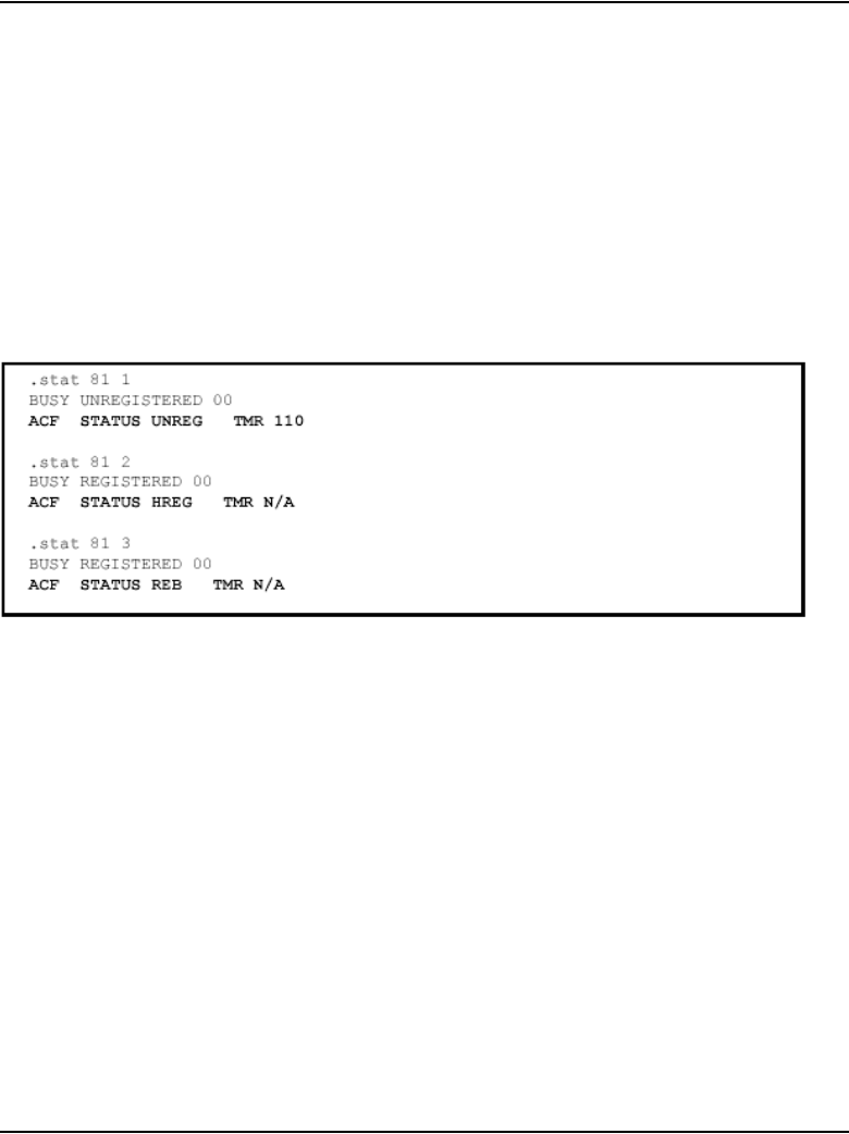
Features Page 101 of 910
IP Line Description, Installation and Maintenance
• REB for rebuilt calls
• PREB for partially-rebuilt calls
where <timer> is:
• an integer value if the timer exists for the call
• N/A if there is no Call Server ACF timer attached
See Figure 5 on page 101.
Figure 5
LD 32 STAT output with ACF example
LD 80 TRAC command
If ACF information exists for the requested IP Phone, it is output as follows:
ACF STATUS <status> TMR <timer> ORIG <orig_state> TERM <term_state>
where <status> is:
• UNREG for unregistered calls
• HREG for half-registered calls
• REB for rebuilt calls
• PREB for partially-rebuilt calls
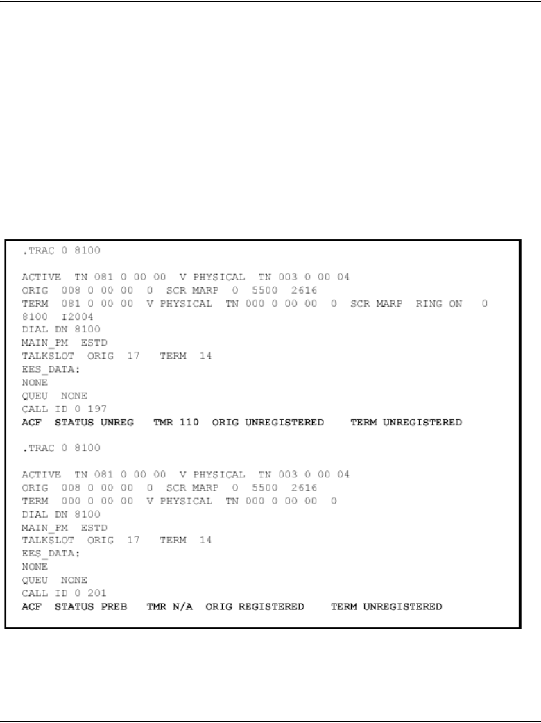
Page 102 of 910 Features
553-3001-365 Standard 4.00 August 2005
where <timer> is:
• an integer value if the timer exists for the call
• N/A if there is no Call Server ACF timer attached
ORIG <orig_state> and TERM <term_state> can be REGISTERED or
UNREGISTERED.
Figure 6 on page 102 is a sample output for IP Phones involved in
UNREGISTERED and PARTIAL-REBUILT calls.
Figure 6
LD 80 TRAC with ACF example

Features Page 103 of 910
IP Line Description, Installation and Maintenance
LD 117 STIP ACF command
A new sub-command ACF is added to the existing LD 117 STIP command.
Output
The output is similar to the existing LD 117 STIP output, with the addition of
a new column titled ACF STATUS. If the call is in an inactive state, the value
of the Call Server ACF timer follows that status, separated by a colon (:).
See Figure 7 on page 104 for an example of STIP ACF output using the ALL
parameter.
Table 15
LD 117 – STIP ACF command
Command Description
STIP ACF <status> Displays the Active Call Failover (ACF) information.
<status> – optional parameter. Specifies the status to be
output. Outputs all IP Phones involved in the following
types of calls:
• UNREG - UNREGISTERED calls
• HREG - HALF-REGISTERED calls
• REB - REBUILT calls
• HREB - HALF-REBUILT calls
• PREB - PARTIAL-REBUILT calls
• ALL – all types of ACF calls
If no status parameter is entered, all types of ACF calls
are output.
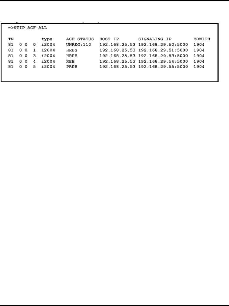
Page 104 of 910 Features
553-3001-365 Standard 4.00 August 2005
Figure 7
LD 117 STIP ACF with ALL parameter output example
LD 117 STIP ACF in Element Manager
Support for the STIP ACF command in LD 117 is provided by Element
Manager. Access to the STIP ACF command is on the Ethernet Diagnostics
web page.
Figure 8 on page 105 illustrates the placement of the STIP ACF command
with the other STIP commands.
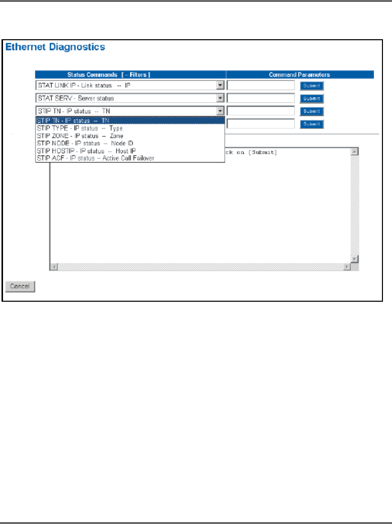
Features Page 105 of 910
IP Line Description, Installation and Maintenance
Figure 8
LD 117 STIP ACF in Element Manager
Figure 9 on page 106 illustrates the list of STIP ACF command parameters
that are made available once the STIP ACF command is selected. The ALL
command parameter is displayed as the default.
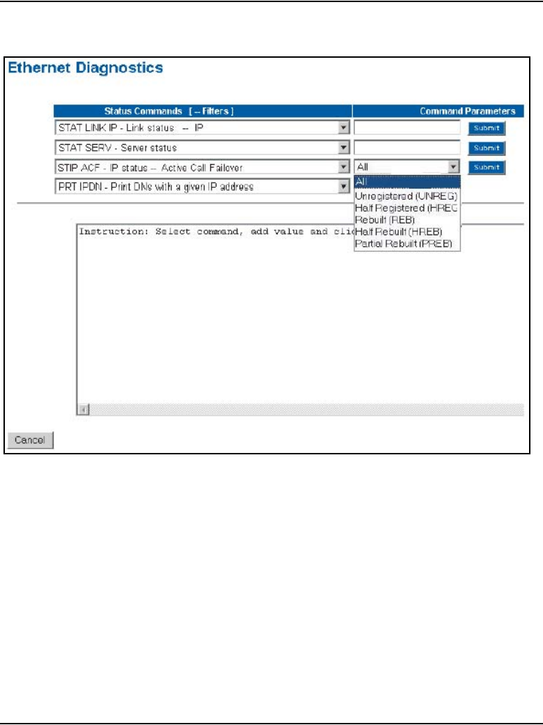
Page 106 of 910 Features
553-3001-365 Standard 4.00 August 2005
Figure 9
LD 117 STIP ACF in Element Manager with parameters
Click the Submit button after selecting one of these available parameters to
execute the command. The output from the command is displayed in the text
box located in the lower portion of the web page.
Online Help describes the various parameters available for the STIP ACF
command.
isetShow command
If the ACF status exists for the requested IP Phone, it is provided in the State
field of the isetShow command output. The ACF status is separated from the
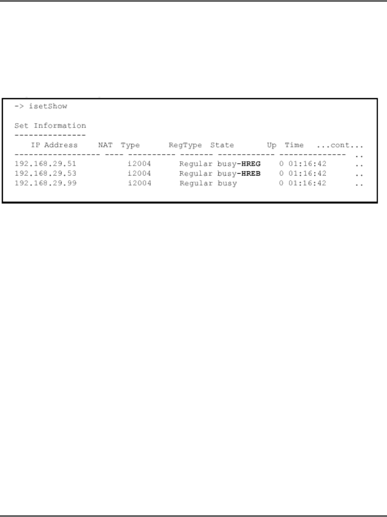
Features Page 107 of 910
IP Line Description, Installation and Maintenance
state by ‘-’ (dash). The ACF status is any value described in the LD 80 output.
The Call Server ACF timer value is not provided in the output.
See Figure 10.
Figure 10
isetShow command output with ACF example
DSP peg counter for CS 1000E systems
The conversion of TDM voice to IP packets is performed by DSP resources
residing on a Voice Gateway Media Card in the IP Media Gateway (IPMG)
of a CS 1000E system. The Voice Gateway Media Cards have a limited
number of DSP resources that actually perform the conversion. When all DSP
resources are busy, calls are blocked.
The DSP Peg Counter feature provides three counters. The first peg counter
provides a count of the number of attempts to allocate a DSP resource on an
IPMG. The second provides a count of the number of times calls were
blocked on an IPMG due to a lack of DSP resources. If the call failed due to
a lack of bandwidth, this is reflected in the third peg counter. The counters are
a part of customer traffic measurement in LD 2.
For more information, refer to Traffic Measurement: Formats and Output
(553-3001-450) and Software Input/Output: Administration (553-3001-311).

Page 108 of 910 Features
553-3001-365 Standard 4.00 August 2005
Enhanced UNIStim Firmware Download for IP Phones
CS 1000 Release 4.5 introduces the Enhanced UNIStim Firmware Download
for IP Phones feature. This feature provides an improved method of
delivering new firmware for Nortel IP Phones.
Specifically, this feature introduces the following functionality:
• Enhanced firmware file header that includes the IT_TYPE and name
string for each IP Phone type. Element Manager and the LTPS can read
this information and automatically display the mapping to the
administrator.
• Revised definition of the IP Client’s IP Phone identification.
• Maximum number of simultaneous firmware downloads from the
Signaling Server’s UNIStim FTP (UFTP) server is 100.
• New Maintenance Mode for the Signaling Server that allows even more
simultaneous firmware downloads from the UFTP server.
• Maintenance Mode (Turbo Mode) that is manually initiated by the
administrator in which pre-marked node Signaling Servers utilize all
possible resources for processing firmware upgrade jobs.
Note: Turbo Mode is not applicable to Voice Gateway Media Cards.
• Improved identification of the registered IP Phones using string names
and providing more detailed identification of telephones that register as
emulations of the base IP Phone 2001/2002/2004 types
• UNIStim IP Phones are allowed to register with an older version of
firmware if the UFTP servers are busy, then periodically offers the option
to start the firmware upgrade to the IP Phone’s user.
• Introduction of missing firmware file retrieval to the Branch Office from
the Main Office.
This new functionality requires a Signaling Server to be present in the node.
Without a Signaling Server, as in the Meridian 1, the only firmware files
available for downloading are the three available in CS 1000 Release 4.0 for
the Phase 0/1/2 IP Phones type 2001/2002/2004.

Features Page 109 of 910
IP Line Description, Installation and Maintenance
The firmware files for the IP Phone 2001, IP Phone 2002, and IP Phone 2004
Phase 0/1/2 phones are distributed to the Voice Gateway Media Cards so
those cards can share in the download of the firmware files to those
IP Phones. Firmware files of all other IP Phones are only stored on and
downloaded from the Signaling Server.
New system management commands are provided to collect information
about registered IP Phones, their models, and their firmware.
Operating parameters
Since the Enhanced UNIStim Firmware Download feature is functional only
on a Signaling Server, the feature does not operate on a Meridian 1 system. It
is supported on the following systems running CS 1000 Release 4.5 (or later)
software:
• CS 1000S
• CS 1000M Cabinet
• CS 1000M Chassis
• CS 1000M HG
• CS 1000M SG
• CS 1000M MG
• CS 1000E
Note: Some enhancements, such as postponed upgrades, are available
on Meridian 1 systems.
The Enhanced UNIStim Firmware Download feature has the following
operating parameters:
• It supports only firmware downloads performed by the UFTP server to
the UNIStim IP Phones supporting the UFTP download protocol.
• Enhanced functionality is provided only if the recommended commands
are used. For example, use of the VxWorks shell copy command instead
of the firmwareFileGet command bypasses the other features and
is therefore not supported.

Page 110 of 910 Features
553-3001-365 Standard 4.00 August 2005
• Firmware retrieval mechanism described for the Branch Office LTPS
retrieves only firmware files it finds missing. It does not compare the list
of firmware on the Branch Office LTPS and Main Office LTPS to
determine whether the Branch Office has the latest firmware, or perform
any automatic compare and update operations. The Branch Office LTPS
only receives firmware files when the umsUpgradeAll command was
issued on the Main Office LTPS.
Feature interactions
Active Call Failover for IP Phones
The Active Call Failover feature handles cases when an IP Phone registers
with an active RTP stream (has a call active at the time of registration). The
check of IP Phone firmware is skipped in this case, and the IP Phone registers
with the LTPS.
The Active Call Failover scenario is the same as the postponed firmware
upgrade scenario described in Table 19 on page 114. After the call ends, the
user is prompted to start the firmware upgrade.
For more information on Active Call Failover for IP Phones, refer to “Active
Call Failover for IP Phones” on page 75.

Features Page 111 of 910
IP Line Description, Installation and Maintenance
System view
IP Phone firmware upgrades
Each IP Phone registering with the LTPS is queried for its firmware ID and
IT_TYPE. The system response depends on the results of the query. See
Table 16.
Firmware file management
To manage available firmware, the following information is collected about
each firmware file on the Signaling Server/Voice Gateway Media Card:
• firmware ID
• firmware version
• applicable IT_TYPE (see Table 17)
• applicable model names
Table 16
System response
Query result Response
LTPS software supports the reported
IT_TYPE (see Table 17 on page 112), and the
Upgrade Manager has firmware for the given
firmware ID.
Registration of the IP Phone continues. The
IP Phone firmware upgrade is performed if
possible.
LTPS software supports the reported
IT_TYPE, but the Upgrade Manager has no
firmware for the given firmware ID.
Registration of the IP Phone continues with no
firmware download.
LTPS software does not support the IT_TYPE
reported.
Registration of the IP Phone is rejected.
The branch office IP Phone is upgraded at the
branch office before the IP Phone is
redirected to the main office.
If the branch office does not have the
necessary firmware file, an attempt is made to
download the firmware file from the main
office.

Page 112 of 910 Features
553-3001-365 Standard 4.00 August 2005
IT_TYPEs
Table 17 lists the IT_TYPES supported by the Upgrade Manager for CS 1000
Release 4.5.
Two events trigger data about firmware files to be updated by the LTPS:
1LTPS reboot
2new firmware file upload from either the LTPS Command Line Interface
(CLI) or Element Manager
In the first case, the LTPS explores possible locations of firmware files and
collects information about found files in its internal database. In the second
case, when a new firmware file is uploaded, the LTPS updates the internal
database with information extracted from the file.
Element Manager uses data from the firmware file to provide information
about the firmware file and the IP Phones to which it can be downloaded.
Table 17
Supported IT_TYPES
IT_TYPE User interface has all attributes of...
0x02 IP Phone 2004
0x03 IP Phone 2002
0x04 IP Phone 2001

Features Page 113 of 910
IP Line Description, Installation and Maintenance
Firmware file names
Firmware file names are originally in the format SSFFYxx.bin.
See Table 18.
The files are renamed according to the following rules:
• Phase 0/1 IP Phone 2004 firmware is renamed to x00.fw
• Phase 1 IP Phone 2002 is renamed to x01.fw
• All other firmware files are renamed to xNN.fw, where:
—x emphasizes that NN is a hexadecimal number
—NN is the firmware ID for that file
The xNN.fw format also applies to the firmware file for the Phase 2
IP Phone 2001, IP Phone 2002, and IP Phone 2004. The file is currently
named IPP2SET.fw and is renamed to x02.fw to conform to the naming
convention.
Table 18
Original firmware file name format
Designator Definition Values
SS Site code where firmware
was built
06 – Calgary
30 – Ottawa
FF Firmware type 02 – Phase 0/1 IP Phone 2004
03 – Phase 1 IP Phone 2002
04 – Phase 2 IP Phone 2001/2002/
2004
YAlpha character A – 0
B – 1
C – 2
D – 3
(and so on)
XX Release number 2-digit decimal integer (for
example,.38)

Page 114 of 910 Features
553-3001-365 Standard 4.00 August 2005
Download maximums
The following modifications are introduced on the Signaling Server to the
Upgrade Manager:
• The default number of allowed simultaneous downloads is increased to
100.
• A new Maintenance Mode (Turbo Mode) that is manually initiated by the
administrator is available in which pre-marked node Signaling Servers
utilize all possible resources for processing firmware upgrades.
The following commands are used to manage the Maintenance Mode:
— uftpTurboMode
— uftpTurboModeTimeoutSet
— uftpTurboModeShow
For more information on Maintenance Mode, refer to “Maintenance
Mode” on page 116.
Immediate and delayed firmware downloads
The IP Phones display various messages to indicate the status of IP Phone
registration and firmware downloads. Table 19 lists some scenario examples
with the resulting IP Phone displays.
Table 19
IP Phone registration and download scenarios (Part 1 of 2)
Scenario Result
Normal firmware download
for known IP Phone type
IP Phone displays message that IP Phone is connecting to the
LTP S.
IP Phone displays message that firmware download is initiated.
If download is successful, IP Phone continues with normal
registration.

Features Page 115 of 910
IP Line Description, Installation and Maintenance
Postponed firmware
upgrade
IP Phone displays message that IP Phone is connecting to the
LTP S.
IP Phone cannot download firmware. It is allowed to proceed
with registration using old firmware.
At the completion of call (if download resources are available), IP
Phone displays message Upgrade F/W now?
IP Phone displays Yes and No softkeys to use to select choice.
If Yes is selected, firmware download begins. If no choice is
made, IP Phone proceeds with firmware download after timer
expiration.
If No is selected, IP Phone display returns to idle state. Off-hook
dialing, on-hook dialing, and external events such as an
incoming call imply a No response.
Unknown firmware ID for
known IT_TYPE
IP Phone displays message that IP Phone is connecting to the
LTP S.
No firmware upgrade is performed, but IP Phone is allowed to
register.
Unknown IT_TYPE IP Phone has no display. The IP Phone just resets continuously.
IP Phone registration is not allowed.
Log message is sent to LTPS administrator.
Branch Office LTPS
determines IP Phone
requires firmware upgrade
IP Phone displays message that firmware download is initiated.
IP Phone is placed into local mode.
Message is displayed until firmware is downloaded. IP Phone’s
upgrade process is initiated.
If firmware download is unsuccessful after 10 retries, IP Phone
remains in local mode.
Table 19
IP Phone registration and download scenarios (Part 2 of 2)
Scenario Result

Page 116 of 910 Features
553-3001-365 Standard 4.00 August 2005
Maintenance Mode
When a Signaling Server is placed into Maintenance Mode, the allowable
maximum number of simultaneous firmware downloads increases.
Maintenance Mode enables the UFTP server to utilize most of its processing
resources to deal with the downloads.
The actual number of simultaneous downloads is determined by measuring
the CPU idle time, so each new firmware download session is launched if one
of the following is true:
• there are less than five download sessions currently active
• Signaling Server or Voice Gateway Media Card is in regular mode (not
in Maintenance Mode) and its CPU usage is less than 85%
• Signaling Server is in Maintenance Mode and its CPU usage is less than
100%
and there are less than 100 download sessions for the Signaling Server (or 15
for Voice Gateway Media Card) already taking place.
The UMS tries to launch a pending download session every five seconds.
Note: When Maintenance Mode is enabled, call processing signaling
could be impacted by the UFTP download processes.
Once Maintenance Mode is enabled, it can be exited in several ways:
• manually, by using the uftpTurboMode “stop” command
• automatically, after the Upgrade Manager is idle for MM minutes after
at least one download has been started
This prevents a time-out from occurring while the system is being
configured and the downloads start. Once a download starts, if MM
minutes pass with no new firmware upgrade jobs starting, the normal
mode of operation resumes. The idle timeout timer is configured using
the uftpTurboModeTimeoutSet command.
• automatically, after expiration of the Maintenance Mode period

Features Page 117 of 910
IP Line Description, Installation and Maintenance
Active firmware upgrade jobs are not cancelled when the Maintenance Mode
exits. No new jobs are added until the number of active jobs is below the
default value.
Maintenance Mode can be enabled only on the Signaling Server.
Maintenance Mode affects only Signaling Servers designated for
Maintenance Mode. This allows some Signaling Servers in the node to
operate in Maintenance Mode while others do not. The Signaling Server is
designated for Maintenance Mode with the uftpTurboMode “on”
command. The Maintenance Mode designation is saved and maintained even
if the Signaling Server is power-cycled or is rebooted. Call processing for
Signaling Servers operating in normal mode is not impacted by the firmware
download process.
Postponed firmware upgrades are not performed when at least one Signaling
Server is in Maintenance Mode.

Page 118 of 910 Features
553-3001-365 Standard 4.00 August 2005
Table 20 lists the commands used for Maintenance Mode.
Table 20
Maintenance Mode commands
Command Description
uftpTurboMode
<“HH:MM/start/stop/on/off”>, <MM>
<“show”>
Configures Maintenance Mode
“HH:MM” – time to enter Maintenance Mode in 24-hour
format
“start” – enter Maintenance Mode immediately
“stop” – stop Maintenance Mode
“on” – allow Signaling Server to enter Maintenance
Mode
“off” – do not allow Signaling Server to enter
Maintenance Mode
MM – optional parameter that defines the length of time
in minutes that Maintenance Mode is to be maintained
“show” – displays the same output as
uftpTurboModeShow
If no parameter is entered, Upgrade Manager defaults
to uftpturboMode “start”.
uftpTurboModeTimeoutSet <MM> Configures the idle timeout timer for Maintenance Mode
MM – optional parameter that defines the number of
minutes the Upgrade Manager waits after the last
firmware download job is started before returning the
Signaling Server to normal mode
If this parameter is configured as 0 (zero), the Upgrade
Manager never exits Maintenance Mode unless the
umsUpgradeModeSet command is issued with the
“stop” parameter.
If no parameter is entered, then the current timeout
setting is displayed.
uftpTurboModeShow Displays current status of Maintenance Mode.

Features Page 119 of 910
IP Line Description, Installation and Maintenance
The following is an example of output when Maintenance Mode is to start at
11 p.m.
oam> uftpTurboMode “23:00”
oam> 28/07/04 08:23:56 LOG0006 shell: F/W upgrade
Maintenance Mode will start after 52564 seconds
Call Server commands
LD 20
A response ISET is introduced to the LD 20 TYPE prompt. When ISET is
entered, the prompt MODEL_NAME is displayed. The MODEL_NAME
prompt allows a user to specify the Short Model Name mnemonic for filtering
the output of TN blocks. If only the ISET response is used, printed TN blocks
contain the long IP Phone Model Name in the output.
The following is an example of the input and output.
>ld 20
REQ: PRT
LD 20 – Listing or printing TN blocks of specified IP Phone model
Prompt Response Description
REQ LTN
PRT
List TN blocks.
Print TN blocks.
TYPE ISET Enable filtering by IP Phone model name.
... ...
MODEL_NAME xxxxxx IP Phone model
For example, 2004P2
... ...

Page 120 of 910 Features
553-3001-365 Standard 4.00 August 2005
TYPE: ISET
TN
CUST
TEN
DATE
PAGE
DES
MODEL_NAME: 2004P2
KEM_RANGE
IP_PHONE_MODEL: IP PHONE 2004 PHASE2
DES FAKE
TN 064 0 00 00 VIRTUAL
TYPE I2004
CDEN 8D
CUST 0
ZONE 000
FDN
TGAR 1
LDN NO
NCOS 0
SGRP 0
RNPG 0
SCI 0
SSU
XLST
SCPW 6400
SFLT NO
CAC_CIS 3
CAC_MFC 0
CLS CTD FBD WTA LPR MTD FND HTD ADD HFD CRPD
MWD LMPN RMMD SMWD AAD IMD XHD IRD NID OLD VCE DRG1

Features Page 121 of 910
IP Line Description, Installation and Maintenance
POD DSX VMD CMSD SLKD CCSD SWD LND CNDD
CFTD SFD MRD DDV CNID CDCA MSID DAPA BFED RCBD
ICDD CDMD LLCN MCTD CLBD AUTU
GPUD DPUD DNDD CFXD ARHD CLTD ASCD
CPFA CPTA HSPD ABDD CFHD FICD NAID DNAA RDLA BUZZ
AGRD MOAD
UDI RCC HBTD AHD IPND DDGA NAMA MIND PRSD NRWD NRCD
NROD
DRDD EXR0
USMD USRD ULAD CCBD RTDD RBDD RBHD PGND FLXD FTTC
DNDY DNO3 MCBN
FDSD NOVD VOLA VOUA CDMR
CPND_LANG ENG
HUNT
PLEV 02
CSDN
AST
IAPG 0
AACS NO
ITNA NO
DGRP
MLWU_LANG 0
DNDR 0
KEY 00 SCR 640 0 MARP
ANIE 0
01
02
03
04
05
06
07

Page 122 of 910 Features
553-3001-365 Standard 4.00 August 2005
08
09
10
11
12
13
14
15
16
17 TRN
18 AO6
19 CFW 16
20 RGA
21 PRK
22 RNP
23
24 PRS
25 CHG
26 CPN
27
28
29
30
31
DATE 8 JUL 2004
NACT

Features Page 123 of 910
IP Line Description, Installation and Maintenance
LD 117
CS 1000 Release 4.5 introduces the following commands in LD 117:
• STIP FW <XX> <A> <BB> <FF> – list IP Phones with specified
firmware ID and, optionally, firmware version. If no parameters are
entered, output is a list of available model names.
• STIP MODL <MMMM> – list IP Phones of specified model name
• RST ZONE <ZoneNumber> <START/STOP> <HH:MM> – reset IP
Phones in specified zone
• RST FW <FWID> <START/STOP> <HH:MM> – reset IP Phones with
specified F/W ID
See Table 21 on page 124.

Page 124 of 910 Features
553-3001-365 Standard 4.00 August 2005
Table 21
LD 117 commands (Part 1 of 2)
Command Description
STIP FW <XX> <A> <BB> <FF> Displays information from the Resource Locator Module
(RLM) for IP Phones with specified firmware ID and
running specified firmware version.
<XX> – firmware ID
<A> – major version designator
<BB> – minor version designator
<FF> – filter to apply on firmware version; can be one of
the following:
= – equal to
~ – not equal to
< – less than
> – greater than
Only the XX parameter is required.
STIP FW <XX> <A> <BB> is equivalent to STIP FW <XX>
<A> <BB> EQ.
STIP FW <XX> <A> lists all registered IP Phones with
firmware ID equal to <XX> and major version designator
equal to <A>.
STIP FW <XX> lists all registered IP Phones with firmware
ID equal to <XX>.
STIP MODL <MMMM> Displays information from the RLM for all IP Phones of the
specified model, where:
• MMMM = IP Phone model
If the <MMMM> parameter is omitted, a table of existing
model names and associated mnemonics is displayed.

Features Page 125 of 910
IP Line Description, Installation and Maintenance
RST ZONE <ZoneNumber> Immediately hard-resets all IP Phones, where:
• ZoneNumber = zone number
RST ZONE <ZoneNumber>
<START/STOP> <HH:MM>
Schedule or cancel hard-resets of all IP Phones in
specified zone.
<ZoneNumber> – zone number in which to reset
IP Phones
START/STOP – IP Phones reset, where:
— START – configures reset time schedule
— STOP – cancels scheduled reset
If START is specified and the last parameter is omitted,
then IP Phones are reset immediately.
<HH:MM> – hour and minute when IP Phones are to be
reset
With only the first parameter, or no parameters, the
schedule of IP Phones re-sets is printed.
RST FW <FWID>
<START/STOP> <HH:MM>
Hard-resets all IP Phones with specified firmware ID.
<F/W ID> – firmware ID of IP Phones that should be reset
<START/STOP> – schedules/cancels IP Phones
hard-reset. If START is specified and the last parameter is
omitted, then IP Phones are reset immediately.
<HH:MM> – hour and minute when IP Phones should be
reset
With only the first parameter, or with no parameters
specified, the schedule of IP Phones resets is printed.
Table 21
LD 117 commands (Part 2 of 2)
Command Description

Page 126 of 910 Features
553-3001-365 Standard 4.00 August 2005
LTPS CLI commands
CS 1000 Release 4.5 introduces the following LTPS CLI commands:
• firmwareFileGet
• uftpAutoUpgradeTimeoutSet
• isetFWShow
• isetFWGet
See Table 22.
Table 22
LTPS CLI commands (Part 1 of 2)
Command Description
firmwareFileGet <“ServerIP”>,
<“UserID”>, <“Password”>,
<“/path/to/file”>, <“Filename”>
Initiates a firmware download from a specified FTP
server. After the download is completed, the
downloaded file is checked for Enhanced Header (or
proper naming). If the file is considered a valid firmware
file, the UMS database is updated accordingly.
ServerIP – FTP server IP address from where the
firmware will be retrieved
UserID, Password – credentials for logging into the FTP
server
/path/to/file – absolute or relative path to the firmware
file (does not include the file name itself)
Filename – name of the firmware file on the FTP server
Note: Use the firmwareFileGet command instead of
firmwareFileGetI2004, firmwareFileGetI2002, and
firmwareFileGetIPP2.

Features Page 127 of 910
IP Line Description, Installation and Maintenance
firmwareFileGet example
pdt>firmwareFileGet “192.168.0.1”,”admin1”,”0000
“,”/u/fw”,”0604D45.BIN”
firmwareFilePut example
pdt>firmwareFilePut “192.168.0.1”,”admin1”,”0000
“,”/u/fw”,”0604D45.BIN”
uftpAutoUpgradeTimeoutSet <MM> Configures the length of time the IP Phone waits for a
user response after the “Upgrade F/W now?” message
is displayed before automatically beginning the
firmware upgrade.
MM – user response timeout in minutes.
A value of 0 (zero) means “Print current settings”.
If no parameter is entered, the current value is printed.
isetFWShow Displays the status of IP Phones firmware.
isetFWGet <filter> Filters the output of the isetFWShow command by one
of that command’s output field names.
Field names include:
•IP
• Model Name
• Type
•FWID
• Supported
•FWVsn
• UNIStim
•TN
Table 22
LTPS CLI commands (Part 2 of 2)
Command Description

Page 128 of 910 Features
553-3001-365 Standard 4.00 August 2005
uftpAutoUpgradeTimeoutSet output example
pdt> uftpAutoUpgradeTimeoutSet 4
pdt> 25/08/04 06:22:23 LOG0006 shell: New value of auto
F/W upgrade timeout is 240 seconds.
pdt> uftpAutoUpgradeTimeoutSet
pdt> 25/08/04 06:22:23 LOG0006 shell: Current value of
auto F/W upgrade timeout is 240 seconds.
isetFWShow output example
oam> isetFWShow
Set Information
---------------
IP Address Model ItType FWID Supported FWVsn UNIStimVsn TN
------------------ ------------------- ---------- -------
-------------- ------------ ---------------- ---------
192.168.29.56 Polycom 2033 i2004 0x10 No A.10 2.9 064-00
Total sets = 1
oam>
Note: Polycom 2033 refers to the IP Audio Conference Phone 2033.
isetFWget output example
oam> isetFWGet “FWID==0x10”
Set Information
---------------
IP Address Model ItType FWID Supported FWVsn UNIStimVsn TN
------------------ ------------------- ---------- -------
-------------- ------------ ---------------- ---------
192.168.29.56 Polycom 2033 i2004 0x10 No A.10 2.9 064-00
Total sets = 1
oam>

Features Page 129 of 910
IP Line Description, Installation and Maintenance
Modified LTPS CLI commands
The output of the following commands has been changed to print IP Phone
model name (long or short), firmware ID, firmware version, and so on:
• isetShow
• uftpShow
• umsPolicyShow
•isetGet
Note: Short model name example is “2004P2”. Long model name
example is “IP Phone 2004 Phase 2”.
isetShow output example
The output has been modified to display the IP Phone Model Name and
firmware version in ABB format.
oam> isetShow
Set Information
---------------
IP Address NAT Model ItType RegType State Up Time Set-TN Regd-TN
HWID FWVsn UNIStimVsn SrcPort DstPort
------------------ ---- ------------------- ---------- -------
-------- -------------- ------------ ------------
-------------------------- ------- ---------- ------- -------
192.168.29.56 IP Phone 2004 i2004 Regular online 0 00:00:32
064-00 064-00 18-006038ddc6b6-6600 B.65 2.8 5100 5000
Total sets = 1
oam>
uftpShow output example
The output has been modified to display the IP Phone Model Name, firmware
ID, and firmware version in ABB format.
oam> uftpShow
------------ UFTP Server Configuration -------------
UFTP Server IP address.......... 192.168.29.42 [port: 5105]
Concurrent downloading limit.... 15 sets

Page 130 of 910 Features
553-3001-365 Standard 4.00 August 2005
Total firmware = 5
FW ID FWVsn Model PolicyName FileName
---------- ---------- -------------------- -------------
----------------
0x00 B.65 IP Phone 2004 DEFAULT /ums/i2004.fw
0x00 B.65 IP Phone 2002 DEFAULT /ums/i2002.fw
0x02 D.44 IP Phone 2001 DEFAULT /ums/x02.fw
0x02 D.44 IP Phone 2002 Ph2 DEFAULT /ums/x02.fw
0x02 D.44 IP Phone 2004 Ph2 DEFAULT /ums/x02.fw
------------------- Run Time Data ------------------
Last UFTP reset................. 1/14/2096 08:38:19
Cumulation Period............... 0004 01:55:01
Successful downloads............ 1
Fail downloads............ 0
---------------- Active Downloads -----------------
Current downloading sets........ 0
Model IP Address Downloaded[KByte]

Features Page 131 of 910
IP Line Description, Installation and Maintenance
umsPolicyShow output example
The output has been modified to display the IP Phone Model Name, firmware
ID, and firmware version in ABB format.
isetGet output
The output has been modified to display the IP Phone Model Name and
firmware version in ABB format.
pdt> umsPolicyShow
T
otal policies = 1
Name Upgrade Protocol Retries
--------------- ------- -------- -------
DEFAULT ANY UFTP 5
Available firmware:
FW ID FWVsn Model Policy Name File name
----- ----- -------------------------------- --------------- --------------
0x00 B74 IP Phone 2004 Phase 0/1 DEFAULT /u/fw/x00.fw
0x00 B70 IP Phone 2002 DEFAULT /u/fw/x01.fw
0x02 D92 IP Phone 2004 Phase 2 DEFAULT /u/fw/x02.fw
0x02 D92 IP Phone 2002 Phase 2 DEFAULT /u/fw/x02.fw
0x02 D92 IP Phone 2001 Phase 2 DEFAULT /u/fw/x02.fw
T
otal firmware = 3

Page 132 of 910 Features
553-3001-365 Standard 4.00 August 2005
Element Manager
To support the Enhanced UNIStim Firmware Download for IP Phones
feature, the following changes have been made to Element Manager:
• Extraction and display of information from the Enhanced firmware file.
For example, when new firmware is downloaded to Element Manager’s
firmware location from the FTP server, Element Manager examines the
file for the text string containing firmware ID, firmware version,
applicable IT_TYPEs, and model names.
• Ability to upload a new firmware file to the LTPS using the
firmwareFileGet command.
• Addition of an interface for initiating or obtaining the status for the
firmware download Maintenance Mode using the CLI commands
uftpTurboMode, uftpTurboModeShow, and
uftpTurboModeTimeoutSet.
• Addition of an interface for resetting IP Phones by firmware ID and zone
using the LD 117 commands RST FW and RST ZONE.
• Output of either ECNT MODL is parsed to obtain the list of available
IP Phone models. This output can be used to allow a user to transparently
specify the model name; that is, Element Manager replaces the actual
model name with associated mnemonic.
• Addition of an interface for displaying the output of the LD 117
commands ECNT MODEL, ECNT FW, ECNT PEC, STIP MODL, and
STIP FW.
• Management of the compatibility matrix of different firmware versions
with the Call Server and LTPS software release using the output of these
LD 117 commands.
• Interaction with the Nortel Software Download web site to download
bundles of firmware files.
IP Phone firmware management in Element Manager
IP Phone firmware management is divided into two parts:
1selecting IP Phone firmware to download
2distributing selected IP Phone firmware

Features Page 133 of 910
IP Line Description, Installation and Maintenance
Selecting IP Phone firmware to download
Follow the steps in Procedure 1 to select the IP Phone firmware files to
download.
Procedure 1
Selecting IP Phone firmware
1Log into Element Manager.
2From the navigator on the left, select IP Telephony > Software >
Telephony Firmware.
See Figure 11 on page 134.
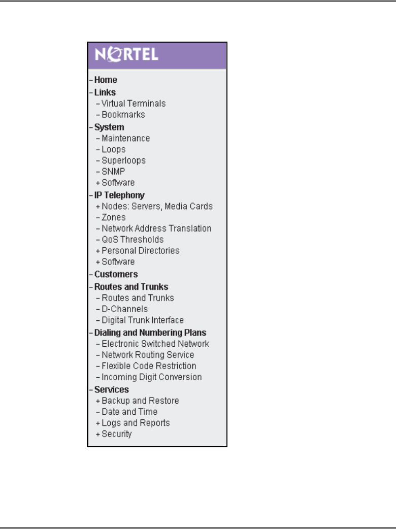
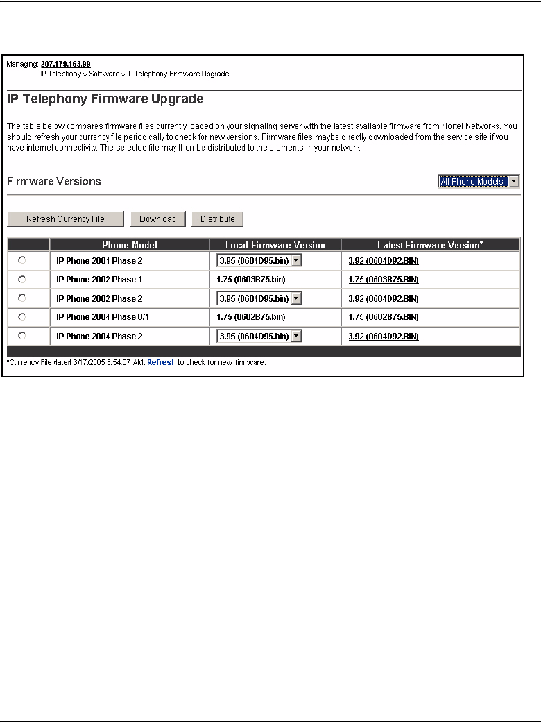
Features Page 135 of 910
IP Line Description, Installation and Maintenance
Figure 12
IP Telephony Firmware Upgrade window
3Choose the IP Phone type firmware file to upgrade by clicking the radio
button.
The various IP Phone models are displayed along with the associated
firmware files.
Note: Figure 12 displays a comparative view of the firmware files present
in the Signaling Server and the firmware files available on the Nortel
service web site. This display shows firmware files already downloaded
and firmware files available on the web site that may not have been
downloaded. If more than one version of a firmware file is present on the
Signaling Server, then the local firmware column displays all versions in
a drop-down list while highlighting the latest one.
4Click Download or click the link for the desired firmware in the Latest
Firmware Version column.
The Latest Firmware Version column displays if a new firmware file
version is available.
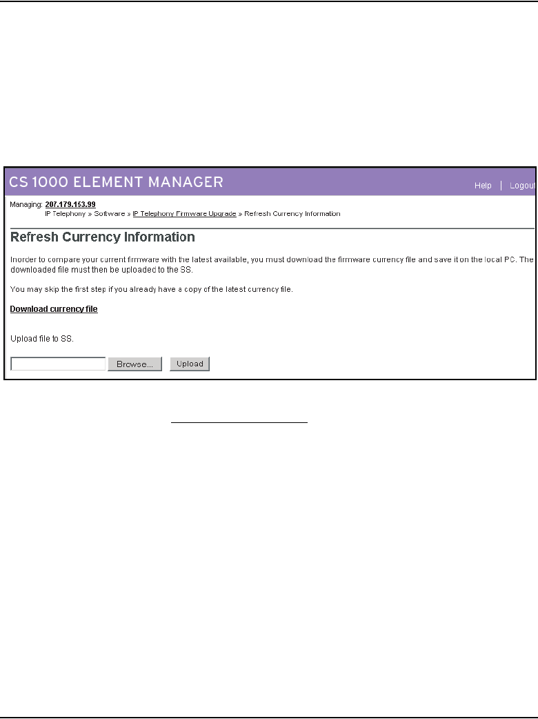
Page 136 of 910 Features
553-3001-365 Standard 4.00 August 2005
The currency file is contained in a file on the Nortel web site and has to be
downloaded to the Signaling Server.
If desired, obtain the most current firmware version by clicking Refresh
Currency File.
The Refresh Currency Information window opens. See Figure 13.
Figure 13
Refresh Currency Information window
5Click Download currency file.
A File Download message box opens. See Figure 14 on page 137.
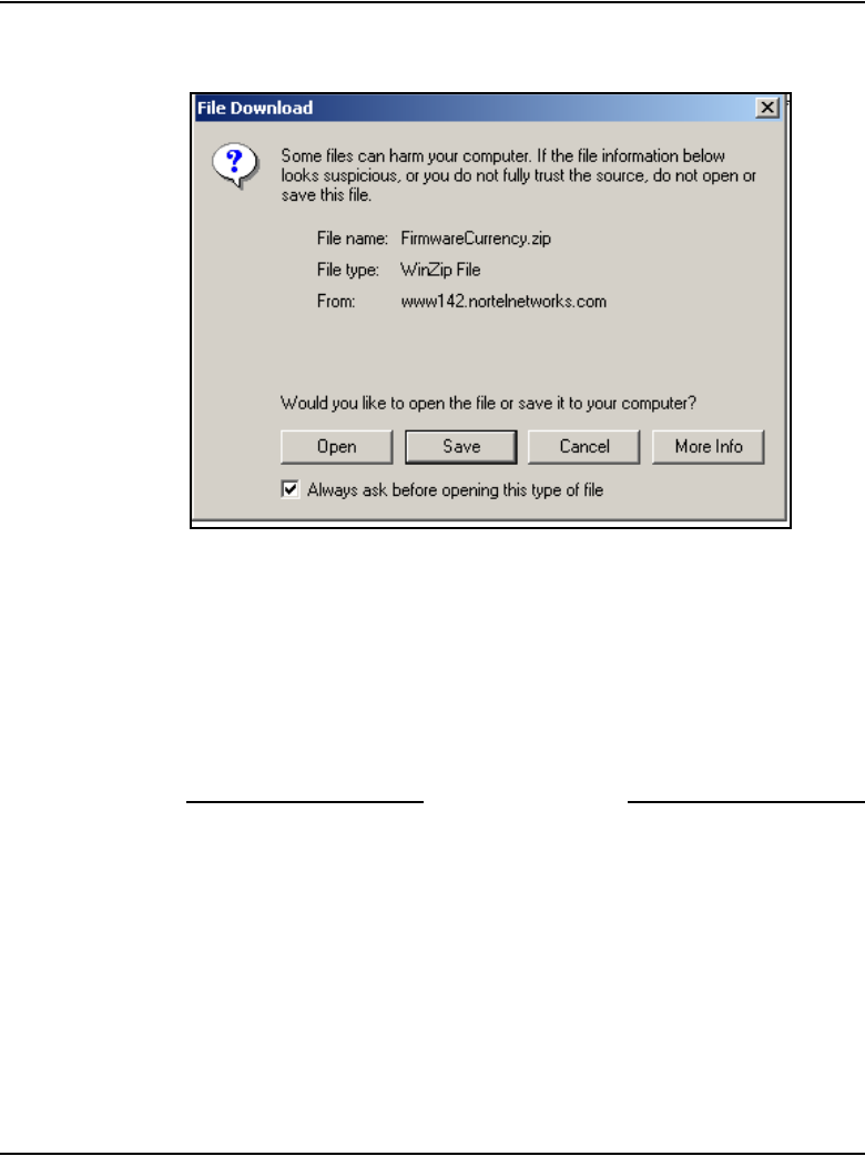
Features Page 137 of 910
IP Line Description, Installation and Maintenance
Figure 14
File Download message box
6Save the file to the desired location on the PC.
7In the Refresh Currency Information window, click Browse and locate
the Signaling Server where the firmware file is to be uploaded.
8Click Upload.
After the upload is completed, the IP Telephony Firmware window
opens, as seen in Figure 12 on page 135.
End of Procedure
Distributing selected IP Phone firmware
IP Phone firmware files can be distributed either to nodes or to individual
elements in the network. A maximum of four elements can be selected at one
time.
Follow the steps in Procedure 2 on page 138 to distribute the IP Phone
firmware files to various elements in the network.
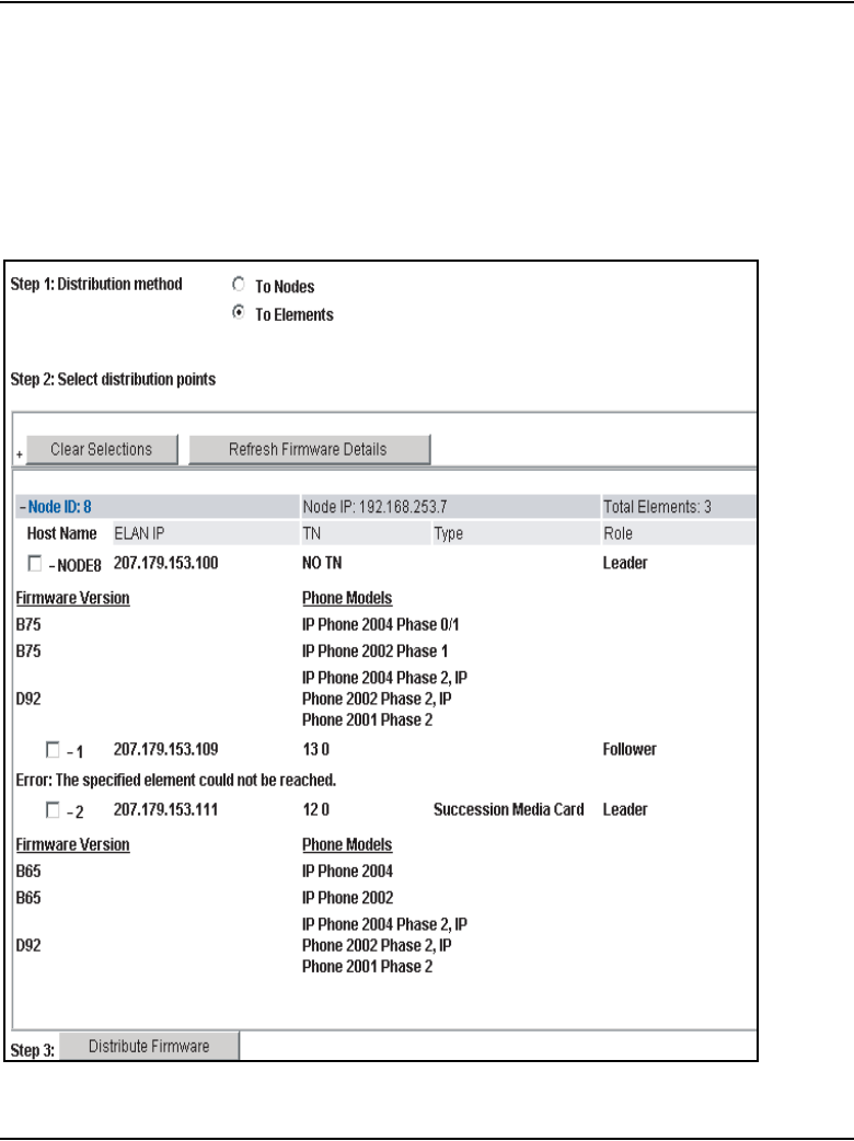
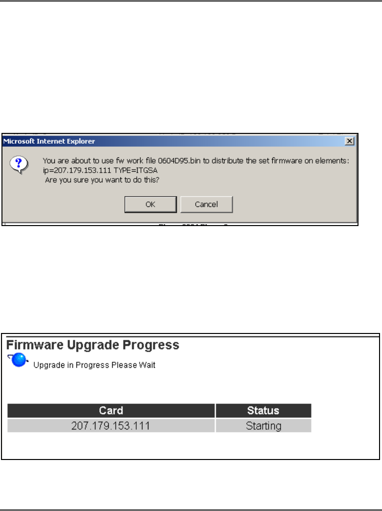
Features Page 139 of 910
IP Line Description, Installation and Maintenance
2Click a radio button to select whether to distribute firmware files to Nodes
or Elements in Step 1 of the window.
3Select the distribution points in Step 2 of the window.
4Click Distribute in Step 3 of the window.
The Confirm firmware distribution message box is displayed. See
Figure 16.
Figure 16
Confirm firmware distribution message box
5Click OK.
The Firmware Upgrade Progress window opens.
See Figure 17 on page 139 and Figure 18 on page 140
Figure 17
Firmware Upgrade Progress window – Starting
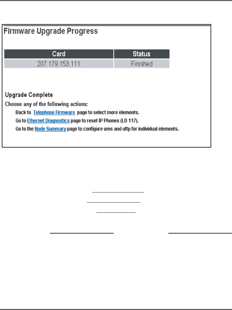
Page 140 of 910 Features
553-3001-365 Standard 4.00 August 2005
Figure 18
Firmware Upgrade Progress window – Finished
The progress is displayed and constantly refreshed. When the firmware
upgrade has completed, Finished is displayed under Status.
6When the upgrade has finished, click one of the following options:
• Back to Telephone Firmware page to select more elements.
• Go to Ethernet Diagnostics page to reset IP Phone (LD 117).
• Go to the Node Summary page to configure ums and uftp for
individual elements.
End of Procedure
Ethernet Diagnostics in Element Manager
To access Ethernet Diagnostics in Element Manager, follow the steps in
Procedure 3.
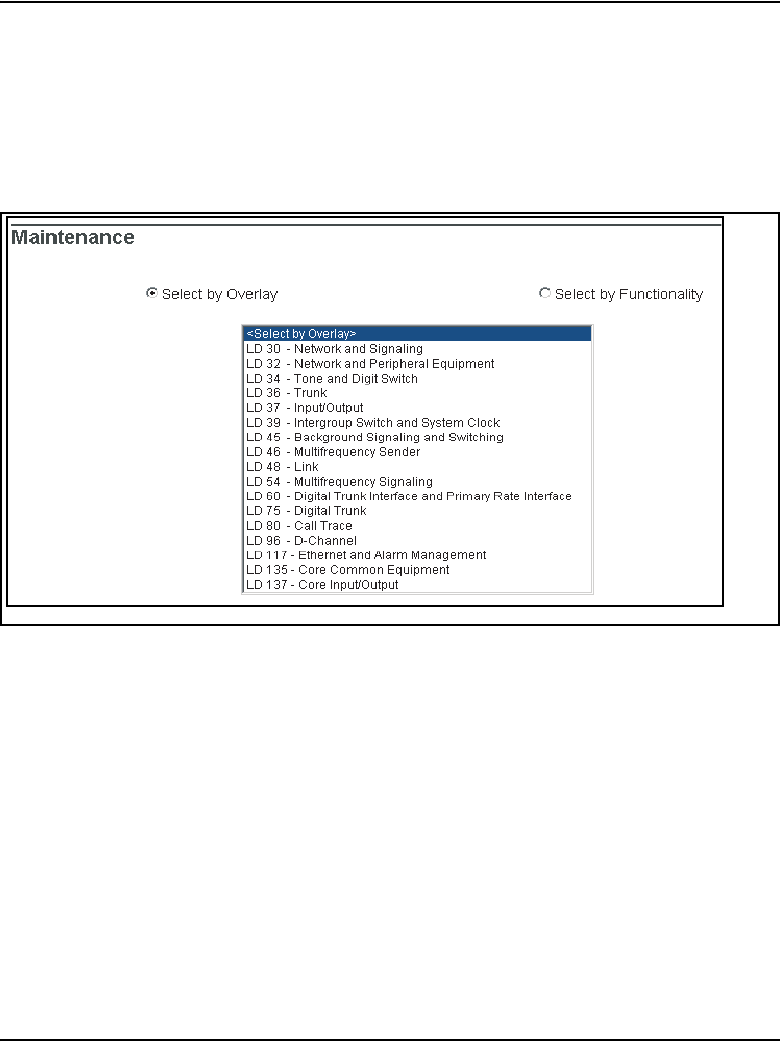
Features Page 141 of 910
IP Line Description, Installation and Maintenance
Procedure 3
Accessing Ethernet Diagnostics in Element Manager
1In the Element Manager navigator, select System > Maintenance.
The Maintenance window opens. See Figure 19.
Figure 19
Maintenance window
By default, the Select by Overlay radio button is selected.
2Select LD 117 – Ethernet and Alarm Management in the <Select by
Overlay> list and then select Ethernet Diagnostics in the <Select
Group> list.
The Ethernet Diagnostics window opens. See Figure 20.
Alternatively, select the Select by Functionality radio button.
Select Ethernet Diagnostics from the <Select by Functionality> list.
See Figure 21 on page 143.
The Ethernet Diagnostics window opens.
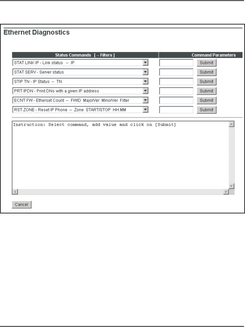
Page 142 of 910 Features
553-3001-365 Standard 4.00 August 2005
Figure 20
Ethernet Diagnostics window
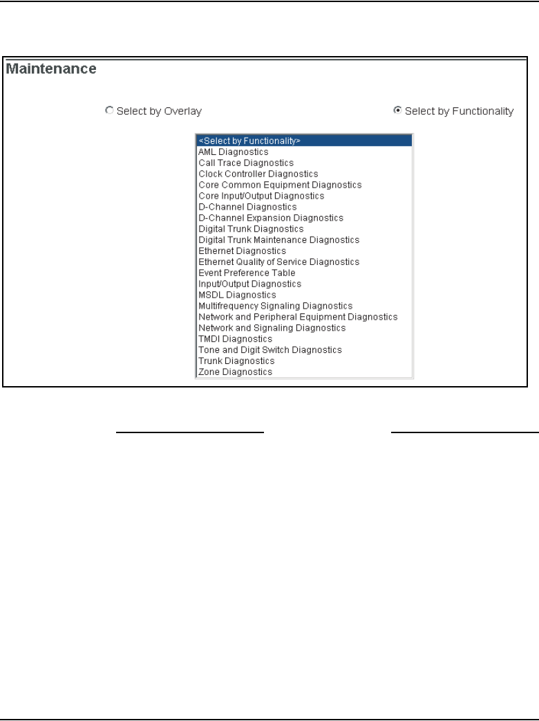
Features Page 143 of 910
IP Line Description, Installation and Maintenance
Figure 21
Select by Functionality list
End of Procedure
For more information on the LD 117 commands, refer to “LD 117” on
page 123.
ECNT commands
The following commands are available in LD 117 under ECNT in the Status
Command list. See Figure 22 on page 144.
•ECNT FW
• ECNT MODL
•ECNT PEC
• ECNT CARD
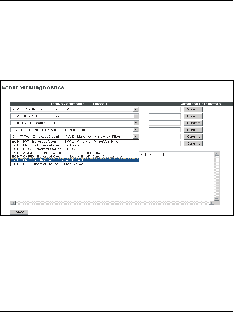
Page 144 of 910 Features
553-3001-365 Standard 4.00 August 2005
• ECNT NODE
•ECNT SS
• ECNT ZONE
Note: ECNT CARD, ECNT NODE, ECNT SS, and ECNT ZONE were
formerly found in LD 32.
Figure 22
ECNT commands
STIP commands
STIP MODL and STIP FW are listed in the STIP commands in the Status
Command list. See Figure 23 on page 145.
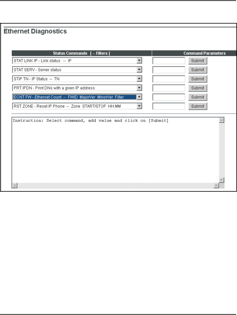
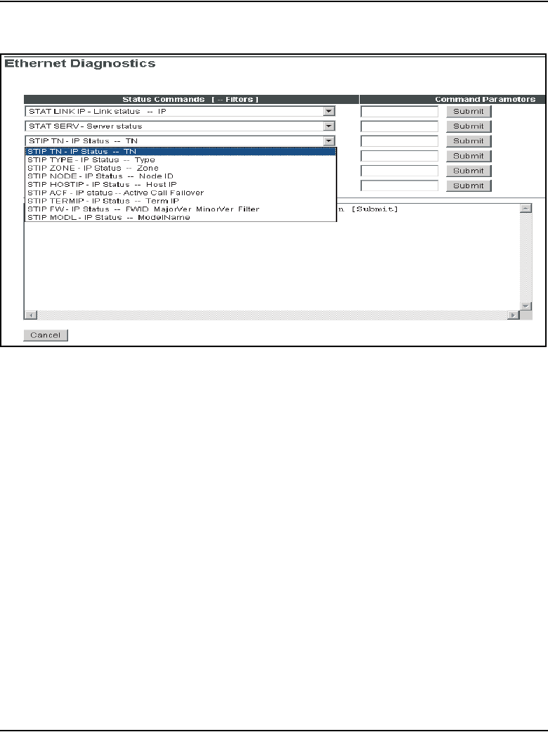
Page 146 of 910 Features
553-3001-365 Standard 4.00 August 2005
Figure 24
RST commands
Maintenance Mode commands in Element Manager
The Signaling Server Maintenance Mode (Turbo Mode) commands are as
follows:
• uftpTurboMode
• uftpTurboModeShow
• uftpTurboModeTimeoutSet
• uftpAutoUpgradeTimeoutSet
To access the Maintenance Mode commands, follow the steps in Procedure 4
on page 147.
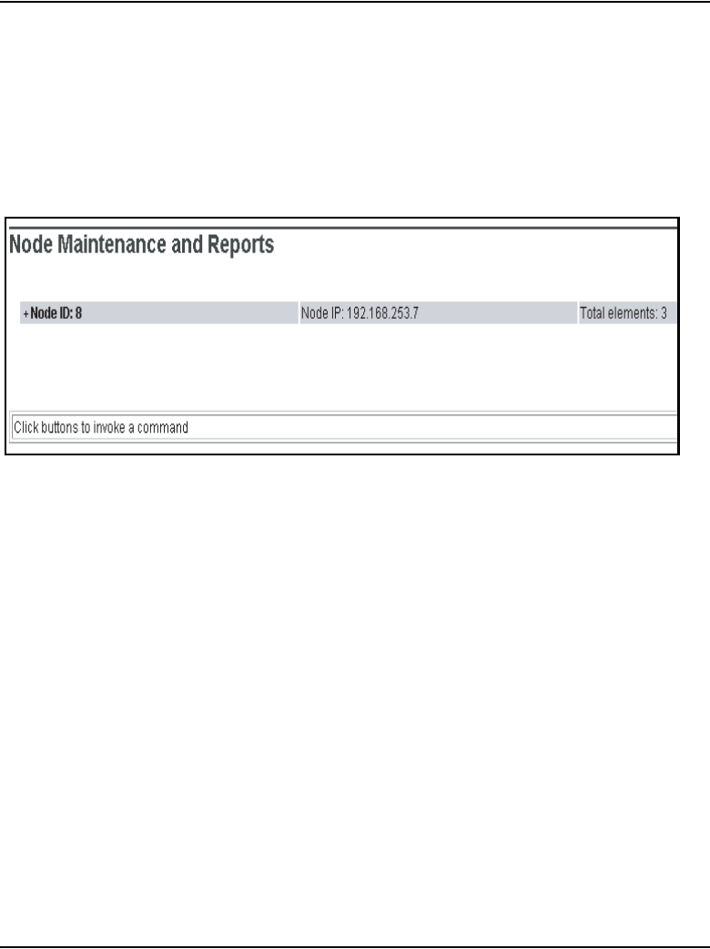
Features Page 147 of 910
IP Line Description, Installation and Maintenance
Procedure 4
Accessing the Maintenance Mode commands
1In the navigator, select IP Telephone > Nodes: Servers, Media Cards >
Maintenance and Reports.
The Node Maintenance and Reports window opens. See Figure 25.
Figure 25
Node Maintenance and Reports window
2Click the plus sign (+) to the left of the Node ID of the desired node to view
the node elements.
See Figure 26 on page 148.
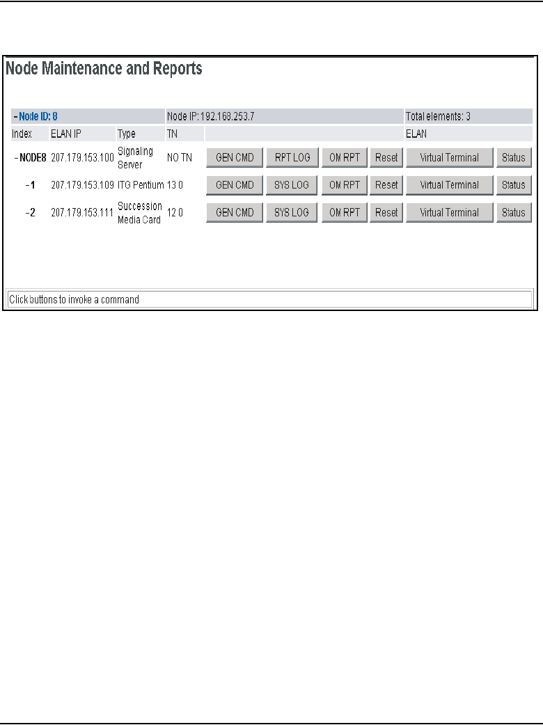
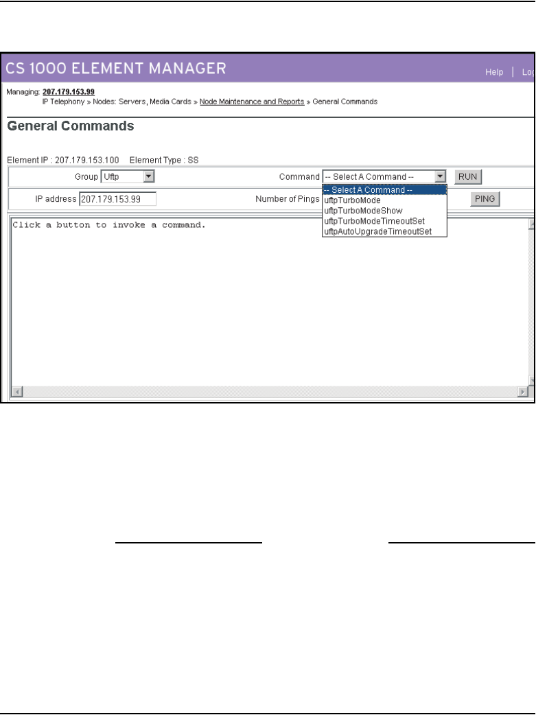
Features Page 149 of 910
IP Line Description, Installation and Maintenance
Figure 27
General Commands window
4From the Group drop-down list, select uftp.
5From the Command drop-down list, select the desired command and
enter any necessary parameters.
6Click Run.
The command output is displayed in the pane below the command.
End of Procedure
Iset commands in Element Manager
Access isetFWShow and isetFWGet in the General Commands window
from the iset group in the Group drop-down list.

Page 150 of 910 Features
553-3001-365 Standard 4.00 August 2005
Firmware download using UNIStim FTP
Previously, IP Phones on CS 1000 and Meridian 1 systems downloaded their
firmware using Trivial File Transfer Protocol (TFTP). Firewalls often have
their well-known TFTP port (port 69) disabled to maintain security. When
port 69 is blocked, IP Phones cannot obtain firmware downloads. This
situation prevents the IP Phone from registering and coming into service.
In order to eliminate the file transfer problem with the firewalls and TFTP, a
UNIStim File Transfer Protocol (UFTP) download solution is implemented.
UFTP enhances security, because it is a proprietary protocol, as opposed to
TFTP which is an open protocol. It enables customers to improve their
firewall security by closing port 69 to block TFPT in their firewall and
policy-based switches and routers.
If a network firewall is in use, ports 5100 (UNIStim signaling) and 5105
(UFTP signaling) must be explicitly opened in the IP Phone-to-UFTP server
direction. Opening these ports enables UNIStim and UFTP firmware
download messages to travel through the firewall. Both of these ports can be
safety enabled by firewalls. See Table 23.
IMPORTANT!
For the UFTP IP Phone firmware download to work, it is necessary to
explicitly open port 5100 (UNIStim signaling) and port 5105 (UFTP
signaling).
Table 23
Source/destination port usage on either side of the connection
Port IP Phone signaling IP Phone UFTP UFTP Server
Source port 5000 (see note) 5000 (see note) 5105
Destination port 5100 5105 5000 (see note)
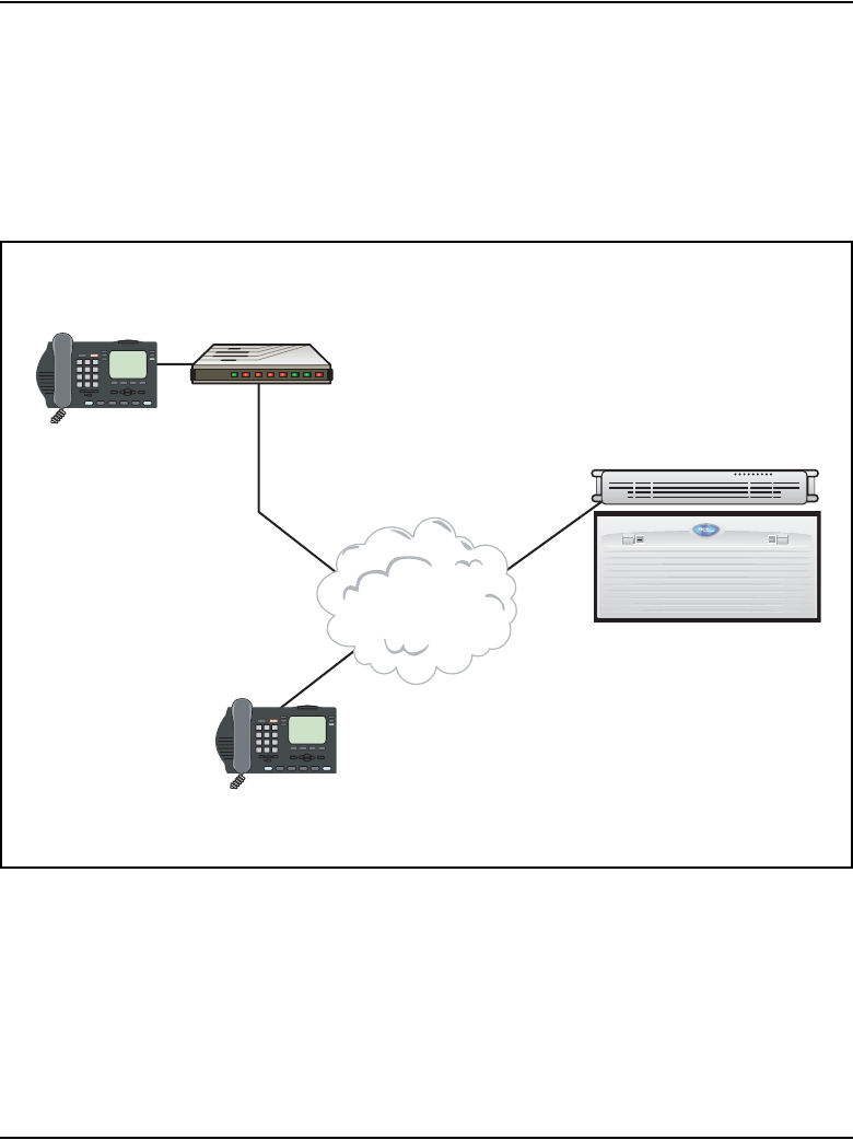
Features Page 151 of 910
IP Line Description, Installation and Maintenance
Note: The UFTP firmware download is compatible with the NAT
Traversal feature. If the IP Phone is behind a Network Address
Translation (NAT) device, then a different public signaling port is used.
The public signaling port is assigned dynamically. See Figure 28 on
page 151.
Figure 28
Using NAT with UFTP
Two Download log files log the results of the UFTP firmware downloads:
“uftplog0.txt” and “uftplog1.txt”. One file is active and one file is inactive.
When a file is full, it becomes the inactive file, and the other file is written to.
The active file displays the most recent entries.
Private IP
Information:
IP: 192.168.0.101
DN: 23215
Signaling Port: 5000
UFTP Port: 5000
Audio Port: 5200
IP: 47.10.221.201
DN: 42121
Signaling Port: 5000
UFTP Port: 5000
Audio Port: 5200
CS 1000
Release 4.5 System
Node IP: 47.10.220.100
TLAN IP: 47.10.220.105
Signaling Port: 5100
UFTP Port: 5105
Public IP Information
IP: 47.10.221.114
DN: 23215
Signaling Port: 1500 (dynamic)
UFTP Port: 1500 (dynamic)
Audio Port: 1501 (dynamic)
NAT router
192.168.0.1 <-> 47.10.221.114
IP Cloud

Page 152 of 910 Features
553-3001-365 Standard 4.00 August 2005
On Voice Gateway Media Cards, the log files are located in the /C:/LOG
directory. The Download log files are limited to 10K each for a total of 20K.
Approximately 128 log messages can be saved in each log file.
On the Signaling Server, the log files are located in the /U/LOG directory.
The Download log files are limited to 400K each, for a total of 800K.
Approximately 5000 log messages can be saved in each log file.
The Download log files are generated during initialization of the UFTP
Server task. If the Download log files do not exist during the start-up of the
UFTP Server task, new Download log files are created.
The Download log file is a circular file, writing over the oldest information
when the log file is full. Each log file entry contains the following download
information about the IP Phone:
• F/W download date
• F/W download start time
• F/W download status (specifies if the download succeeded or failed)
• IP Address of the IP Phone
• IP Phone type
• F/W download error code. If the F/W download was successful, this field
is empty. The following is the list of all possible error codes:
— 00 = F/W not exist
— 01 = F/W size is 0
— 02 = F/W corrupted
— 03 = RUDP connection down
— 04 = Response time out
— 05 = Reason: Unknown
The format of the download log message is:
<Date> <Download start time> <Download Status> <IP address of the IP
Phone> < IP Phone type> <Error Code>

Features Page 153 of 910
IP Line Description, Installation and Maintenance
The following is an example of the Download log message:
31/01/04 17:04:36 F/W Dnld fail:(47.11.215.44) i2004 Ph2
(F/W Corrupted)
31/01/04 17:05:46 F/W Dnld success:(47.11.215.44) i2004
CLI commands
The following CLI commands support UFTP firmware downloads:
• uftpNodeShow
• uftpShow
• uftpRunTimeDataReset
• activeDlogShow
• inActiveDlogShow
• dnldFailShow
uftpNodeShow
The uftpNodeShow command provides a complete UFTP IP Phone firmware
download summary of each node. This includes the configured cards in the
node that are not responding.
Each node summary contains the following information:
•Index
• TN - LL S CC or C C
•Host Type
• TLAN IP Address
• Data Period
• Active Download Count (Act)
• Server Up Time (Srv Up Time)
• Successful Download Count (Ok)
• Failure Download Count (Fail)
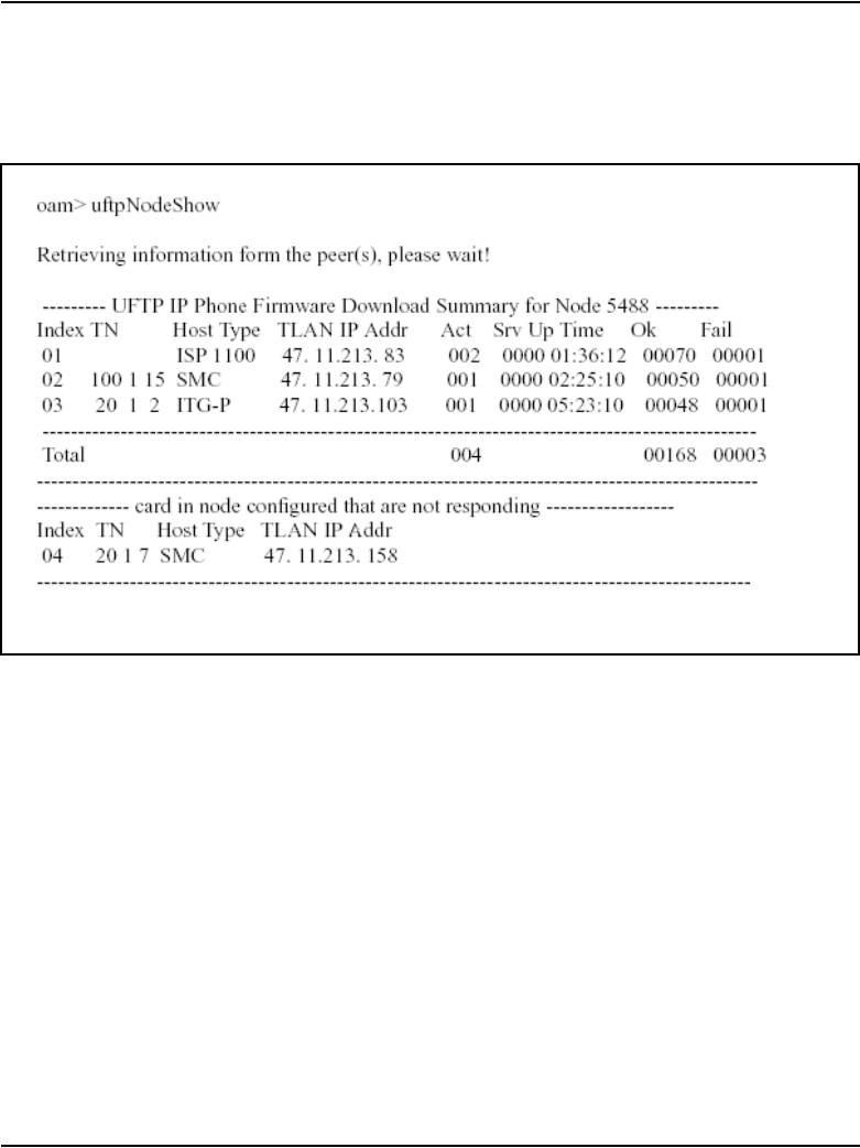
Page 154 of 910 Features
553-3001-365 Standard 4.00 August 2005
Figure 29 on page 154 is an example of output from the uftpNodeShow
command.
Figure 29
uftpNodeShow command output
uftpShow
The uftpShow command displays the following information:
• configuration information about UFTP
• count of successful downloads since the Signaling Server/Voice
Gateway Media Card reboot
• count of downloads that failed or prematurely ended since the Signaling
Server/Voice Gateway Media Card reboot
• number of active downloads, and a list of each, including:
— type of IP Phone
— IP addresses of the IP Phones that downloaded firmware
— number of bytes downloaded
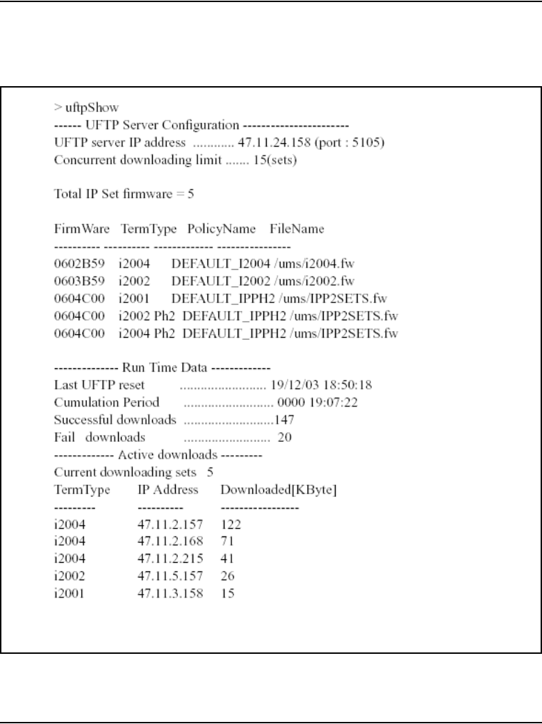
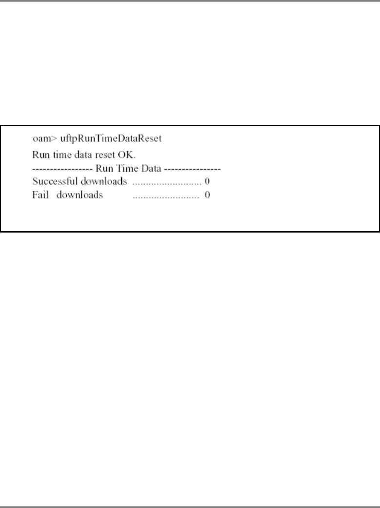
Page 156 of 910 Features
553-3001-365 Standard 4.00 August 2005
uftpRunTimeDataReset
The uftpRunTimeDataReset command is used to reset the run time data
field in the UFTP data block.
Figure 31 is an example of output from the uftpRunTimeDataReset
command.
Figure 31
uftpRunTimeDataReset command output
activeDlogShow
The activeDlogShow command displays the active log file information for
UFTP IP Phone firmware downloads. When no parameter is entered, the
output displays the contents of the entire active log file. When a line number
is entered, activeDlogShow[numOfLine], the output displays the active log
file by the number of lines.
Figure 32 on page 157 is an example of output from the activeDlogShow
command.

Features Page 157 of 910
IP Line Description, Installation and Maintenance
Figure 32
activeDlogShow command output
inActiveDlogShow
The inActiveDlogShow command displays the non-active dlog file
information for UFTP IP Phone firmware downloads. When no parameter is
entered, the output displays the contents of the entire file. When a line number
is entered, inActiveDlogShow [numOfLine], the output displays the
non-active dlog file by the number of lines.
Figure 33 on page 158 is an example of output from the inActiveDlogShow
command.
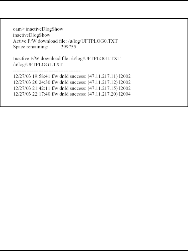
Page 158 of 910 Features
553-3001-365 Standard 4.00 August 2005
Figure 33
inActiveDlogShow command output
dnldFailShow
The dnldFailShow command displays the “download failed” status logged in
the active and inactive files. When no parameter is entered, the output
displays the all the failed UFTP download information in the active and
inactive files. When a line number is entered, dnldFailShow[numOfLine],
the output displays the download fail status in the active and inactive files by
the number of lines.
Figure 34 on page 159 is an example of output from the dnldFailShow
command.
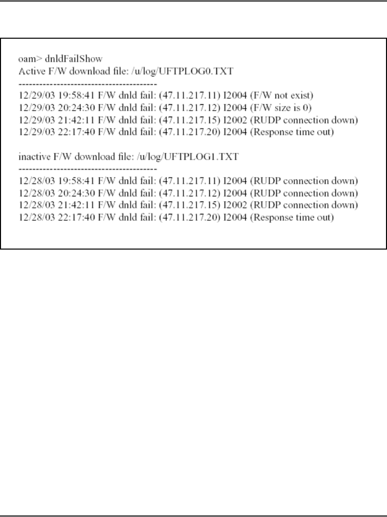
Features Page 159 of 910
IP Line Description, Installation and Maintenance
Figure 34
dnldFailShow command output
NAT Traversal feature
Network Address Translation (NAT) provides the following benefits:
• the ability to network multiple sites with overlapping private address
ranges
• added security for servers on a private network
• conservation of public IP address allocation
A NAT device (router) exists between a private network and a public
network. The NAT device maps private addresses to public addresses.
With the NAT Traversal feature, several IP Phones are now supported behind
a single Cone NAT router with, or without, Virtual Private Network (VPN)
capabilities. This support enables large-scale deployment of Voice over
Internet Protocol (VoIP) in teleworking and Small Office/Home Office
(SOHO) environments.

Page 160 of 910 Features
553-3001-365 Standard 4.00 August 2005
Supported Cone NAT routers include:
• Full Cone
• Restricted Cone
• Port Restricted Cone
Note: A Cone NAT router with more than one IP Phone connected to it
must support hairpinning. Hairpinning occurs when an IP Phone behind
a NAT router can send packets to the Public IP address and port of
another IP Phone connected to the same NAT router.
Echo Servers
NAT Traversal is a function of the CS 1000 Release 4.5 software, and not a
function of the NAT router. NAT Traversal uses two Echo Servers residing
on the Signaling Server. Echo Server 1 detects the presence of a NAT router,
while Echo Server 2 detects the type of NAT router. Both Echo Server 1 and
Echo Server 2 are required for the NAT Traversal feature to function
properly.
If a compatible NAT router is detected, successful IP Phone registration
occurs and the software invokes the NAT Mapping Keep Alive function to
prevent loss of the IP connection. If an incompatible NAT is detected, an error
is displayed on the IP Phone’s display and the IP Phone is not allowed to
register.
Mapping
When an IP Phone is used in a private network behind a NAT device, the
NAT router strips the IP Phone’s private IP address and private port number
and assigns it a public IP address and public port number.
IMPORTANT!
Symmetric NAT routers are not supported. If the IP Phone is behind a
Symmetric NAT, IP Phone registration is unsuccessful and the IP Phone
displays a “NAT Error! ITG3053” message.

Features Page 161 of 910
IP Line Description, Installation and Maintenance
To support multiple IP Phones behind one NAT device, NAT must map
between public/private IP addresses, and ports for each IP Phone behind it.
There is a mapping for both a signaling port and a media (voice) port.
Placing an IP Phone behind Multiple NAT devices is an unsupported
configuration. If it is necessary to have a configuration with multiple NATs
between the IP Phone and the Voice Gateway Media Card, all NATs on the
path must follow the rules described in the following sections for signaling
and media streams.
Mapping is configured and implemented using the NAT device. The IP Line
application does not implement any of the mappings.
NAT and signaling
NAT hides the true identity of the IP Phone from the LTPS. The LTPS is only
aware of any IP Phone based on the public IP address and port of the signaling
messages. A signaling message originates from the IP Phone on the private
side from port 5000. That signaling message is then mapped from the private
side to a public IP and port; that is the IP address seen by the LTPS.
Signaling messages between the Voice Gateway Media Card and IP Phones
are carried by RUDP. Each RUDP connection is distinguished by its IP
address and port number.

Page 162 of 910 Features
553-3001-365 Standard 4.00 August 2005
The NAT device performs private-to-public mapping for the signaling port
for each IP Phone behind it to support multiple IP Phones. The TPS uses fixed
port numbers for signaling. The NAT device must perform consistent
private-to-public mapping for these port numbers. Table 24 lists the UDP port
number used.
Port numbers on the Voice Gateway Media Card use a fixed numbering
scheme where the starting number for the port range is configurable. The first
port on the card uses the configured starting port number; the rest of the port
numbers follow in sequence. Each port has two sequential numbers: one for
RTP and one for RTCP.
Table 24
Signaling UDP Ports
UDP Port Device Use
5000 IP Phone incoming signaling
messages to the
IP Phones, including
UFTP messaging
5100 LTPS incoming call
processing messages
to the LTPS
5105 UFTP incoming UFTP
packets to the UFTP
server
4100 LTPS incoming registration
message to Connect
Server
7300 LTPS incoming registration
messages to node
Master

Features Page 163 of 910
IP Line Description, Installation and Maintenance
Do not change this port at any time. Map this port to port 5200 on the IP
Phones.
NAT Mapping Keep Alive
The normal operation of the LTPS and the IP Phone requires the LTPS to
send a periodic Watchdog Reset UNIStim message. This message resets the
hardware watchdog timer running on the IP Phone and specifies the period for
the time-out. If the LTPS does not send the Watchdog Reset message before
the watchdog timer expires, the IP Phone resets and begins a new registration
cycle with the LTPS.
Table 25
IP Line UDP Ports
UDP Port Device Use
5200-5262 Media Card RTP packets
(configurable starting port number –
IP Phone’s port matches it)
5201-5263 Media Card RTCP packets into Media Card
(port number is RTP port number + 1)
5200-5246 ITG-P 24-port line card RTP packets
(configurable starting port number –
IP Phone’s port matches it)
5201-5247 ITG-P 24-port line card RTCP packets into Media Card
(port number is RTP port number + 1)
5200 IP Phone RTP packets into IP Phone
(port matches first RTP port of the Voice
Gateway Media Card)
5201 IP Phone RTCP packets into IP Phone
(port matches first RTCP port of the Voice
Gateway Media Card)

Page 164 of 910 Features
553-3001-365 Standard 4.00 August 2005
To avoid loss of the IP connection, the NAT Mapping Keep Alive function
sends the Watchdog Reset message more frequently. Default values are
recommended. However, if it is necessary to increase the frequency of the
Reset Watchdog message, increase the NAT Mapping Keep Alive timer
value.
NAT Traversal can be configured to provision the length of time the audio
and signaling port mapping is refreshed. This configuration can be done in
Element Manager, on the Call Server in LD 117, or in OTM through a
window to the Call Server.
By default, all IP Phones behind a NAT device have the signaling and audio
path kept alive. The default value is 30 seconds. The value can be decreased
to 20 seconds or increased to 600 seconds.
Mute and Hold considerations
IP Line 4.5 must handle two special situations when interworking with NAT:
Mute and Hold.
Mute
Table 26 describes the Mute process.
Table 26
Mute process (Part 1 of 2)
Description
Problem
1When a user enables Mute, the LTPS sends a Mute Transmit (Tx) command to the
IP Phone. That command forces the IP Phone to generate silence in the transmit
direction.
2If the IP Phone is using an evocator that implements silence suppression, for
example G.729AB, the IP Phone sends one silence frame to the far end, and then
stops sending any further frames until Mute is cancelled.
3Data sent from the IP Phone stops.

Features Page 165 of 910
IP Line Description, Installation and Maintenance
4The NAT device sees that the IP Phone’s UDP connection is not active in the
transmit direction and starts aging the translation.
5Depending on the length of time the call is muted and the duration of the NAT’s
translation aging timeout value, the NAT device might time-out the translation and
drop the connection.
6All packets coming from the far end are dropped by the NAT device.
7When mute is cancelled, the IP Phone starts transmitting again.
8NAT considers this to be a new connection and creates a new translation. NAT
sends data to the far end using this new translation, resulting in half-duplex voice
connection between the IP Phone and the far-end device.
9Data sent to the far end device gets there but the data coming back is lost.
Solution
1The IP Phone periodically sends an extra non-RTP packet to the far end to keep
the NAT translation alive, ensuring that the NAT’s session time-out does not
expire.
2The non-RTP packet is constructed to fail any RTP validation tests so it is not
played out by the far-end device (IP Phone or gateway channel.
Table 26
Mute process (Part 2 of 2)
Description

Page 166 of 910 Features
553-3001-365 Standard 4.00 August 2005
Hold
The Hold function differs from the Mute function as Hold does not cause
problems with the audio stream. Table 27 describes the Hold process.
NAT and VLANs
Support of Virtual LANs (VLANs) is entirely dependent on the Layer 2
switch to which the IP Phone is immediately connected. Users behind a NAT
router may find that the configuration of a VLAN ID is unsupported by their
NAT router. Refer to the documentation of the NAT router to determine if a
VLAN ID is supported.
Users who attempt to use an IP Phone with VLAN enabled on a NAT router
that does not support VLANs cannot connect to the CS 1000 system. If DHCP
is used, the IP Phone cannot even obtain an IP address.
Note: Most NAT routers do not support 802.1Q Tagging. If 802.1Q
Tagging is not supported on the NAT device, the checkbox Enable
802.1Q support in Element Manager’s Node Summary Page under the
“QoS” Section must be left unchecked. See Figure 35 on page 167. If
Table 27
Hold process
Description
1When an IP Phone user places a call on Hold, the audio stream in both the
Transmit (Tx) and Receive (Rx) directions closes.
2The NAT device begins aging the translation.
When the audio stream is closed and no voice path is present, the IP Phone
defaults to sending periodic non-RTP packets to keep the NAT translation alive.
Therefore, when a call is put on Hold, the IP Phone defaults to sending these
non-RTP packets.
3When the call is retrieved from Hold, a new set of open audio-stream messages is
issued by the LTPS and new connections are established reusing the same NAT
translation.
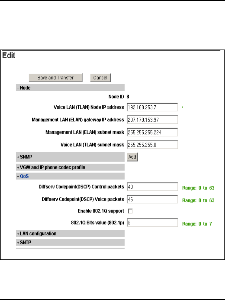
Features Page 167 of 910
IP Line Description, Installation and Maintenance
802.1Q Tagging is enabled for IP Phones behind NAT, the IP Phones can
send the initial “Resume Connection” message, but then the IP Phones
reset and no call path is established.
Figure 35
802.1Q Tagging on Node Summary page in Element Manager

Page 168 of 910 Features
553-3001-365 Standard 4.00 August 2005
NAT Traversal and Proactive Voice Quality Management
Real-Time Control Protocol (RTCP) signaling provides statistics (for
example, latency, packet loss, and jitter) about the Real-Time Transfer
Protocol (RTP) stream. For the RTCP signaling to be successful, the PUBLIC
RTCP port number must be the RTP port number + 1. For example, if the
PUBLIC RTP port is 12000, then the PUBLIC RTCP port must be 12001.
The NAT router typically assigns the RTCP port number as RTP port number
+ 1. However, the NAT router is not guaranteed to properly assign the RTCP
port number. When the RTCP port number is not properly assigned, the
RTCP message exchange fails and the Proactive Voice Quality Management
feature does not receive the required RTCP data. A message is printed to the
LTPS console and syslog file and an SNMP trap (ITG3054) is generated.
The NAT Traversal feature attempts a “best effort” approach to initiate the
NAT router to properly assign the RTPC port number. The “best effort”
approach is dependent on the NAT router’s implementation, may vary from
NAT router to NAT router, and cannot be guaranteed by the NAT Traversal
feature.
Configuring NAT Traversal in Element Manager
To configure the Echo Servers IP addresses/port numbers and NAT Keep
Alive time-out setting using Element Manager, in the Element Manager
navigator select IP Telephony > Network Address Translation.
See Figure 36 on page 169.

Features Page 169 of 910
IP Line Description, Installation and Maintenance
Figure 36
NAT configuration
Configuring NAT Traversal in LD 117
Commands are available in LD 117 to configure and print the Echo Servers
IP addresses/port numbers and NAT Keep Alive time-out setting.
No configuration is required for the Echo Servers to work. The default IP
address of 0.0.0.0 means that Echo Server 1 uses the TLAN network interface
IP address. The default IP address of 0.0.0.0 means that Echo Server 2 uses
the Node IP address.

Page 170 of 910 Features
553-3001-365 Standard 4.00 August 2005
Note: An IP address of 0.0.0.0 means the default local Echo Server will
be enabled.
If IP addresses are specified, they must be for servers external to the system.
The IP addresses cannot be the same. Duplicate IP addresses can only be used
if the default of 0.0.0.0 is used. If the IP addresses are the same (and not
0.0.0.0), an error message is generated and the input is not accepted.
IMPORTANT!
The NAT Traversal feature is essentially automatic. Changing the IP
addresses or ports should only be done in exceptional cases when an
Echo Server external to the CS 1000 system is used.
Table 28
LD 117 commands for NAT (Part 1 of 2)
Command Description
CHG ES1 <Echo Server 1 IP
Address> <Echo Server 1 Port>
Change Echo Server 1’s IP address and port number,
where:
• Default Echo Server 1 IP Address = 0.0.0.0
• Default Echo Server 1 Port number = 10000
Note: Echo Server 1 default IP address uses the TLAN
IP address of the LTPS.
CHG ES2 <Echo Server IP
Address> <Echo Server Port>
Change the Echo Server 2 IP address and port number,
where:
• Default Echo Server 2 IP Address = 0.0.0.0
• Default Echo Server 2 Port number = 10000
Note: Echo Server 2 default IP address uses the
node IP address on the node’s master card.
PRT ES1 Print Echo Server 1’s IP address and port number.
PRT ES2 Print Echo Server 2’s IP address and port number.
PRT ESS Print both Echo Servers IP addresses and port numbers.

Features Page 171 of 910
IP Line Description, Installation and Maintenance
CHG ES1/CHG ES2
If the IP addresses entered for ES1 and ES2 are the same and both are not
0.0.0.0 or for external servers, an error message is generated and the input is
not accepted. Any value between 1000 and 60000 can be entered for the port.
If the port value is outside of that range, an error message is generated. Just
the port (and not the IP addresses) can also be configured. This is
accomplished by entering data similar to the following:
=>chg es1 0 5400
The value 0 for the IP address is interpreted as: 0.0.0.0. This means the Echo
Server runs locally using the configured port value.
The port values both default to 10000. If an IP address is configured, it is also
necessary to configure the port. An error message is generated if no port is
configured but an IP address is configured.
If both Echo Servers are not configured, then the LTPS on the Signaling
Server or the Voice Gateway Media Card uses two local instances of the Echo
Server. If both Echo Servers are configured, then the LTPS uses the external
Echo Servers. If an external Echo Server fails, that functionality is lost unless
the external Echo Server implements a transparent redundancy scheme. The
external Echo Server is responsible for its redundancy and reliability.
CHG NKT <time-out setting> Change NAT Mapping Keep Alive Time-out setting of port
mapping for devices behind a NAT router, where:
time out setting = 20-(30)-600 seconds
PRT NKT Print NAT Mapping Keep Alive Time-out setting of port
mapping for devices behind a NAT router.
Table 28
LD 117 commands for NAT (Part 2 of 2)
Command Description
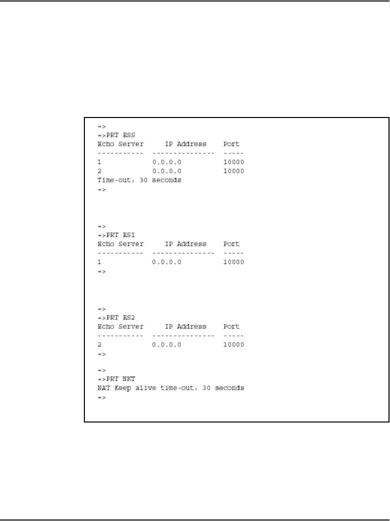
Page 172 of 910 Features
553-3001-365 Standard 4.00 August 2005
PRT commands
Figure 37 is an example of the output of the PRT commands when the
defaults are used. If other IP addresses or port numbers have been configured,
then these appear in place of the 0.0.0.0 or 10000 in the examples in
Figure 37.
Figure 37
PRT commands output
CLI commands
The CLI commands described in this section provide information about IP
Phones behind a NAT device and the Echo Servers

Features Page 173 of 910
IP Line Description, Installation and Maintenance
isetShow
When the isetShow command is used, a NAT column lists the NAT type if an
IP Phone is behind a NAT, where:
• C – Cone NAT
• S – Symmetric NAT
• U – Unknown. Behind a NAT of unknown type (response received from
only Echo Server 1).
• P – Pending. Waiting for response from the IP Phone or the IP Phone
never received a response from Echo Server 1.
• .. – Blank space. Indicates the IP Phone is not behind any kind of NAT
(normal case).
For example (partial output from the left side of the screen):
IP Address NAT Type RegType
47.11.215.183 i2001 Regular
47.11.179.168 C i2004 Regular
47.11.179.167 C i2004 Regular
isetReset
The isetReset command resets an IP Phone based on the entered IP address
or TN. The IP address must be the Public IP address for IP Phones behind a
NAT. If the entered IP address identifies an IP Phone that is behind a NAT
and no other IP Phone are sharing the address, then the IP Phone is reset.
However, if the entered IP address identifies multiple IP Phones (multiple IP
Phones behind a NAT sharing the same public IP address), then an error
message is printed. This message indicates there is more than one IP Phone
with the IP address, lists the IP Phones and their TNs, and recommends using
the isetReset TN command.
For example:
oam> isetReset “47.11.217.102”

Page 174 of 910 Features
553-3001-365 Standard 4.00 August 2005
WARNING: There are 2 IP Phones that use the public IP
address of 47.11.217.102 Please reset the IP Phone using
the TN: isetReset “TN”.
The number of IP Phones that share the same public IP address is printed.
Note: Commands such as isetScpwQuery, isetScpwModify, and
isetScpwVerify have the same error handling as isetReset. If an IP
address is entered that multiple IP Phones are using, an error message
prints. For example,
WARNING: There are 2 IP Phones that use the public IP
address of 47.11.217.102.
isetGet
The isetGet command can search on the NAT type.
NAT = xxx where x is:
• C – the IP Phone is behind a Cone NAT
• S – the IP Phone is behind a Symmetric NAT
• U – the IP Phone is behind a NAT of unknown type (response only
received from Echo Server 1)
• P – waiting on a response from the IP Phone, or the IP Phone never
received a response from Echo Server 1
• .. – Blank space: the IP Phone is not behind any kind of NAT (normal
case)
• Y – true when an IP Phone’s NAT is C, S or U
• N – true when an IP Phone’s NAT is . . (blank), meaning no NAT is
detected

Features Page 175 of 910
IP Line Description, Installation and Maintenance
For example:
IPL> isetGet “NAT == Y”
returns the output (partial output from the left side of the screen):
IP Address NAT Type RegType State Up Time
47.11.179.168 C i2004 Regular online 0 04:20:34
47.11.179.167 C i2004 Regular online 0 03:48:17
isetNATShow
The isetNATShow command outputs information about IP Phones behind a
NAT device.
The public and private IP address and ports are provided for both signaling
and media.
In most cases, the private signaling port information is available. If the
firmware on the IP Phone is outdated, the private signaling port information
is not printed.
If the IP Phone is found to be behind a Symmetric NAT device, the media IP
information is not printed out.
The following is an example of output for a Symmetric NAT device.
Signalling Media
Public IP Addr:Port Public IP Addr:Port
(Private IP Addr:Port) (Private IP Addr:Port) NAT Type RTCP
Type Set-TN Regd-TN
---------------------------- ----------------------------
--------- ---- ------------ ------------- ------------
47.11.217.102:10000 <<No Speech Possible>> Symmetric Y i2002 Ph2
061-08 061-08
(192.168.1.3:5000)

Page 176 of 910 Features
553-3001-365 Standard 4.00 August 2005
The type of NAT is indicated, as detected by Echo Server 2. The support of
RTCP signaling is indicated by Y; if N is displayed, then features that depend
on RTCP, such as Proactive Voice Quality Management (PVQM), will not
work.
An IP Phone’s TN or public signaling IP address can be entered after the
command. Entering the isetNATShow command at the CLI of any card in an
IP Telephony Node along with the TN or IP address of a particular IP Phone
displays the information shown in the previous example, as well as the
identification of the card with which the IP Phone is registered. This is useful
when it is necessary to identify the card on which to enable a message
monitor, or to connect a sniffer, when debugging a specific IP Phone’s
problem.
Figure 38 on page 177 shows a sample output.

Features Page 177 of 910
IP Line Description, Installation and Maintenance
Figure 38
isetNATShow sample output
The command “isetShow” and “isetNATShow” can display the information
about an IP Phone based on IP or TN. The “IP” is the Public IP address used
for signaling. If “isetShow” or “isetNATShow” is typed with a Public IP
address used by multiple IP Phones, then all those IP Phones are displayed,
even if the IP Phones are registered to different cards. Therefore, the
“isetShow” and “isetNATShow” now display the information similar to the
following example:
Signaling....
Public...
(Private...
----
->Found on Card TN 009-00, ELAN IP....
47.11.217.102....
IPL> isetNATShow "47.11.217.102"
value = 0 = 0x0
IPL>
Signalling Media
Public IP Addr:Port Public IP Addr:Port
(Private IP Addr:Port) (Private IP Addr:Port) NAT Type RTCP Type Set-TN Regd-TN
---------------------------- ---------------------------- --------- ---- ------------ ------------- ------------
->Found on Card TN 009-00 , ELAN IP 47.11.217.21, TLAN IP 47.11.216.185 :
47.11.217.102:10000 47.11.217.102:10354 Cone Y i2002 Ph2 061-08 061-08
(192.168.1.3:5000) (192.168.1.3:5200)
->Found on Card TN 009-00 , ELAN IP 47.11.217.21, TLAN IP 47.11.216.185 :
47.11.217.102:10006 47.11.217.102:10007 Cone Y i2004 061-00 061-00
(192.168.1.4:5000) (192.168.1.4:5200)

Page 178 of 910 Features
553-3001-365 Standard 4.00 August 2005
Notice how the “Found on” line is below the title, and is displayed before
every IP Phone.
Note: If a PVQM command is entered with an IP address that multiple
IP Phones are using, then an error message is also printed.
WARNING: There are 2 IP Phones that use the public IP
address of 47.11.217.102
These PVQM commands include:
•RTPStatShow
• RTPTraceShow
• RTPTraceStop
•rPing
•rPingStop
• rTraceRoute
• rTraceRouteStop
• eStatShow
• RUDPStatShow
• isetInfoShow
echoServerShow
The echoServerShow command provides both configuration information
about the Echo Servers and information about interactions with the Echo
Servers for the IP Phones on a specific LTPS. Use this command on an LTPS
card to investigate a problem with an IP Phone registered to that LTPS card.
This is a per-card command that provides information on the Echo Servers
from the viewpoint of the LTPS on the card where the command is entered.
The command has one optional parameter, “action”; the only valid value is
99. When echoServerShow 99 is entered, the counter values are reset after
they are displayed. When just echoServerShow is entered, the counter
values are displayed without being reset.

Features Page 179 of 910
IP Line Description, Installation and Maintenance
The output for each Echo Server displays the following information:
• Configured – the IP address: port configured for this Echo Server in
LD 117
• Actual – the IP address: port used for this Echo Server, followed by an
explanation in parenthesis. This is different from the “Configured”
parameter only when the default address (0.0.0.0) has been configured.
The explanation in parenthesis is one of the following:
— (TLAN IP, this card) – the IP address used is the TLAN network
interface of this card; the Echo Server is active on this card.
— (node IP, this card) – the IP address used is the Node IP address; the
Echo Server is active on this card because it is the node master.
— (node IP, other card) – the IP address used is the Node IP address,
but another card is currently the Node master; the Echo Server is not
active on this card.
— (not this card) – the IP address is not this card’s TLAN IP address or
the Node’s IP address; the Echo Server is not active on this card.
• LTPS request sent – the number of Resolve Port Mapping Request
messages sent from the LTPS to IP Phones, with this Echo Server
identified as the one to contact.
• Failed resp rec.d – the number of Resolve Port Mapping Ack messages
received from the IP Phones that had the public IP address and port
configured as 0.0.0.0:0000. Each increment of this counter indicates an
IP Phone never received the Discover Port Mapping Ack response from
the Echo Server (all 10 attempts failed).
The two peg counts give an indication of the interaction this LTPS is having
with the Echo Server. It is not a direct sign of the health of the Echo Server;
network conditions for IP Phones registered to this LTPS may be preventing
communication with this Echo Server while another LTPS’s IP Phones have
no problem. The echoServerShow command output can help to understand
why a particular IP Phone registered to a LTPS may be having difficulties or
helps to uncover patterns of communication problems between IP Phones and
Echo Servers.
A sample output is shown in Figure 39 on page 180.
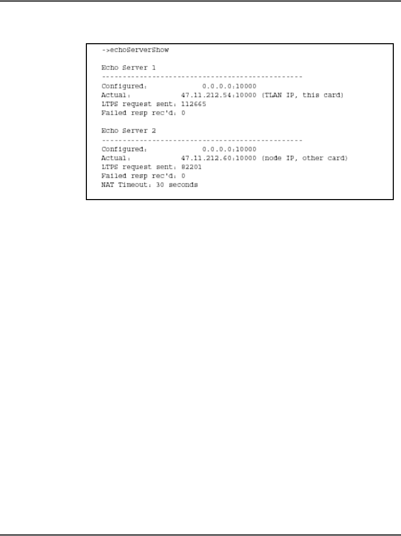
Page 180 of 910 Features
553-3001-365 Standard 4.00 August 2005
Figure 39
echoServerShow sample output
When the echoServerShow command with the reset parameter 99 is entered,
the counter values are displayed and then reset. If the echoServerShow
command is entered again and no requests have since been sent, the counter
values are displayed as 0.
A sample output is shown in Figure 40 on page 181.
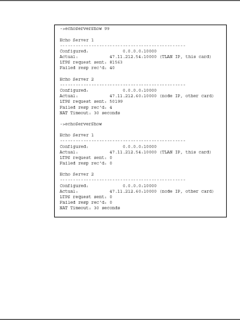
Features Page 181 of 910
IP Line Description, Installation and Maintenance
Figure 40
echoServerShow 99 sample output
vgwShow
The vgwShow command has been modified to allow the optional entry of an
IP Phone’s IP address and port. A search is made of all the Voice Gateway
Media Cards in the node to find the IP Phone’s IP address and port. With the
introduction of NAT Traversal, more than one IP Phone may map to a single
IP address. The command input is modified to allow the entry of the public
port number for a specific IP Phone.
vgwShow <“IPAddr”>, <port>
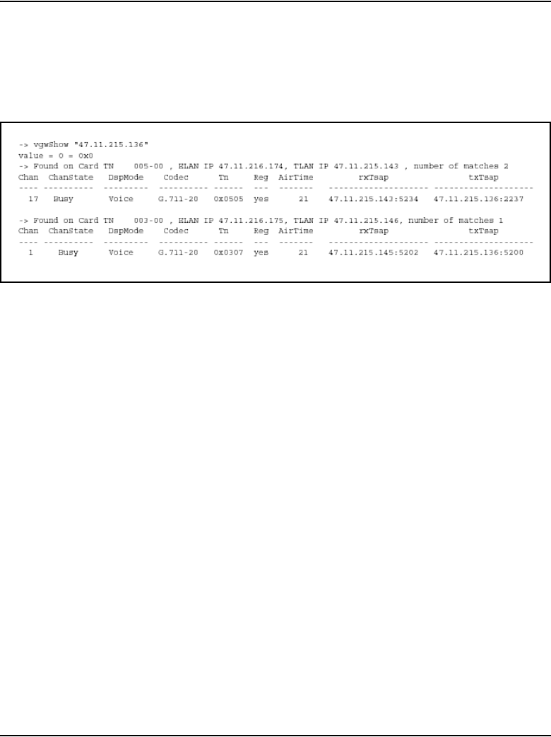
Page 182 of 910 Features
553-3001-365 Standard 4.00 August 2005
If no port number is entered, the first entry found with the specified IP address
on a Voice Gateway Media Card is returned. An example is shown in
Figure 41.
Figure 41
vgwShow with IP address command output
When the IP address is found in the list of VGW channels for a card other than
the card where the command was entered, the VGW channel information for
the first occurrence is returned, plus a count of the number of times the IP
address occurs in that card’s list. Multiple instances can occur when the
customer’s network is configured so that multiple IP Phones are behind a
NAT device sharing the NAT device’s public IP address.
If there is more than one match, the administrator can log into that specific
card and enter the vgwShow command without entering an IP address and
port number. That will print all the busy channels on the card. To quickly find
a particular IP Phone, use the IPDN or DNIP commands in LD 117 to obtain
the IP Phone’s media stream public IP address and port number; then enter
the public IP address and port number as parameters for the vgwShow
command.
Personal Directory, Callers List, and Redial List
The Personal Directory, Callers List, and Redial List features are supported
on CS 1000 systems running CS 1000 Release 4.5 software.

Features Page 183 of 910
IP Line Description, Installation and Maintenance
The Personal Directory allows a user to enter or copy names to a personal
directory, and delete those entries if desired.
The Callers List and Redial List are call log features. The content of these lists
is generated during call processing. A user can scroll through the Callers List
to see who has called. The user can dial a number from the Redial List.
The Personal Directory, Callers List, and Redial List use a separate central
database, called the IP Phone Application Server, to store directory data and
user profile options.
Note: Since the IP Phone Application Server is part of the IP Line 4.5
software on the Signaling Server, the Personal Directory, Callers List,
and Redial List are only supported on CS 1000 systems.
Password protection is available to control access to a user’s Personal
Directory, Callers List, and Redial List.
Fore more information, refer to “Personal Directory, Callers List, and Redial
List” on page 253.
IP Call Recording
IP Call Recording provides the IP address and port information for an
IP Phone in Information Elements (IE) over Application Module Link (AML)
for Meridian Link Services (MLS). This information correlates the TN of a
specific IP Phone with its associated IP address for a call recording
application. When enabled in LD 17, IP Call Recording sends a modified
AML message for each call. The modified message identifies the call’s IP
endpoint and makes it possible to correlate the RTP packets for that call to a
particular IP Phone
IMPORTANT!
CPND must be configured on the system to enable Personal Directory,
Callers List, and Redial List.

Page 184 of 910 Features
553-3001-365 Standard 4.00 August 2005
IP Call Recording introduces the IE pair:
• This Party IP IE (monitored party)
• Other Party IP IE (remote party)
The IP IE pair is similar to the existing IE pairs:
• For DNs: This Party DN IE, Other Party DN IE
• For TNs: This Party TN IE, Other Party TN IE
The IP IEs are optional in the Unsolicited Message Status (USM) (Active)
and USM (Restore) messages. Note the following:
• If the USM message applies to a monitored key on a digital telephone,
then the IP IEs are not sent.
• If the USM message applies to a monitored key on an IP Phone, then the
IP IEs are sent: one for the monitored party and one for the remote party.
A call recording application is provided with status update messages for the
call keys of any IP Phone it is monitoring. These USM messages contain the
IP address and port number information for the monitored IP Phone and the
remote party in the active call. By using a Layer 2 switch that supports port
mirroring, the call recording device can monitor the media stream for the
active call and record it.
Enhanced IP Call Recording
CS 1000 Release 4.5 introduces an enhancement to IP Call Recording that
provides a direct method of capturing and recording VoIP calls. The feature
enhancement implements a mechanism to record the IP media stream to an
external media-recording device by instructing the IP Phone to send a
duplicate media stream to a third-party call-recording application. The
third-party call-recording application provides the recording and playing
function for the IP calls.
This feature enhancement is supported on the Phase II IP Phone 2001, IP
Phone 2002, IP Phone 2004. and IP Softphone 2050.

Features Page 185 of 910
IP Line Description, Installation and Maintenance
The IP Call Recording enhancement enables the following types of recording:
• Bulk Call Recording – All calls are automatically recorded for a
particular IP Phone. The Call Recording application issues a Start
Recording Request message for the User ID, and all calls are recorded
until the Call Recorder application issues a Stop Recording Request.
• Quality Monitor Recording – The Call Recorder records conversation for
a particular call. The Call Recording application can monitor the Call
Recording application (CR) data such as Calling Line ID (CLID) or
Automatic Number Identification (ANI) to determine if it needs to record
a specific call. The Call Recording application issues a Start/Stop
Recording Request to the User ID for only the duration of the specific
call. Quality monitor recording enables manual recording of individual
calls with the following options:
— Call recording can be started or stopped at any time during a call.
— Call recording can also be paused and restarted repeatedly during a
call, enabling excerpts from a conversation to be recorded.
— Call recording can begin retroactively. At any time during the
conversation, the entire call can be saved; it is not necessary to start
recording when the call begins.
— Call recording can be configured to maintain ACD Emergency key
functionality.
The IP Call Recording is initiated by the CR. A Start Recording Request
message is sent that contains the User ID to be recorded and the IP addresses
and port information of where the duplicate media stream is to be sent.
In LD 11, the Class of Service ICRA/ICRD (IP Call Recording Allowed/IP
Call Recording denied) is available for the IP Phones that support IP Call
Recording. The default is IRCD. See “LD 11” on page 190.
Warning tones
If Recording Warning Tone is required, This tone can be turned ON/OFF on
the Call Server using the existing UNIStim message Stream Based Tone
On/Off. The message requires the predefined parameters for the tone, such as
tone ID, frequency and volume.

Page 186 of 910 Features
553-3001-365 Standard 4.00 August 2005
Bandwidth requirements
The use of IP Call Recording doubles the bandwidth requirements of the call.
For example, in a call using the G.711 codec, one voice packet data stream
requires approximately 80 kbps. As the IP Call Recorder uses two separate
streams for the in/out calls, there are four streams requiring a total of 320 kbps
for the voice packet data. In a typical 100 Mbps LAN network environment,
if 80% of the bandwidth was configured for voice data, then this network
could support a maximum of 500 simultaneous IP Phone calls.
(100 x 1000 x 0.8 / 160) = 500
When the IP Call Recording feature is enabled, that same network is limited
to a maximum of 250 calls.
For remote users connecting to the IP Call Recorder Server through a WAN
connection, the impact of the bandwidth usage to the QoS should be
considered. In this case, the IP Call Recorder Server must provide the QoS
parameters when instructing the IP Phone to echo the voice data.
Depending on the IP Call Recorder Server’s ability to handle the RTP stream,
more than one IP Call Recorder Server can be required in a large call center
environment. Middleware (software that connects two sides of an application
and passes data between them) should have an algorithm to balance the traffic
between the different servers.
Feature interactions
Mute key
When the Mute key is pressed, the IP Phone keeps both the primary and the
duplicate audio stream open. When Mute is pressed, the recording state
remains active, but only the incoming conversation is recorded. Pressing the
Mute key a second time resumes normal recording.

Features Page 187 of 910
IP Line Description, Installation and Maintenance
Hold key
When the Hold key is pressed, a Stop Recording Request message is sent
from the Call Server, and the duplicate media stream is closed. A new audio
stream is opened for the other active call. When the hold is released, a new
Start Recording Request is sent from the Call Server to the IP Phone and
recording begins again.
Transfer key
After the Transfer key is pressed and the transfer accepted, the current audio
stream is closed. A new audio stream for the new call is opened, followed by
a Start Recording Request message. If the IP Phone that accepted the
transferred call does not have call recording enabled, the transferred call is not
recorded.
Call Forward
When a call is forwarded, the audio stream is opened for the destination IP
Phone. If the destination IP Phone does not have call recording enabled, the
forwarded call is not recorded.
Conference call
In a conference call, each IP Phone opens a media stream. The IP Phone’s
duplicate media stream to the CR is maintained as long as that IP Phone is part
of the conference.
Note: Agent Observe injects a tone which interferes with the Recording
Warning tone.
Identifying the IP Phone
IP Call Recording requires the unique identification of each IP Phone to be
recorded.
In an Multiple Appearance Directory Number (MADN) configuration, the
Call Server enables the association of two MADN keys on a particular TN.
There is a maximum of two associated (AST) keys per TN.

Page 188 of 910 Features
553-3001-365 Standard 4.00 August 2005
In a Multiple Appearance DN Redirection Prime (MARP) configuration, the
Call Server enables the association of MARP DNs on different TNs. There is
a maximum of two associated (AST) keys per TN.
The following table provides an example of AST configuration in LD 11.
LD 11 – AST configuration (Part 1 of 2)
Prompt Response Description
...
AST ASTKEY1
ASTKEY2
Key numbers to be associated on this TN.
((ASTKEY1 and ASTKEY2 are the numbers of the keys to
be associated. In this example, consider ASTKEY1 = 0 and
ASTKEY2 = 1.)
...
KEY KEY 0 SCR XXXX
MARP ON TN L S
C U
MARP
CPND
VMB
ANIE
XXXX is the DN which is a MARP and already configured
on another TN.

Features Page 189 of 910
IP Line Description, Installation and Maintenance
Administration
LD 17
LD 17 provides the Enhanced Unsolicited Status Message (USM) IE enable
(IPIE) prompt.
The IPIE prompt enables or disables IP Call Recording on a system-wide
basis. The functionality is disabled by default. When enabled, a modified
Application Module Link (AML) message that identifies the IP endpoint is
sent for each call. The IPIE prompt is in LD 17 under system parameters
(PARM).
KEY KEY 1 SCR XXXX
MARP ON TN L S
C U
MARP
CPND
VMB
ANIE
XXXX is the same DN as configured on KEY 0.
...
LD 17 – IP Call Recording (Part 1 of 2)
Prompt Response Description
REQ CHG Change existing data.
TYPE PA R M Change system parameters.
LPIB 96 – 7500 Low priority Input Buffers
...
LD 11 – AST configuration (Part 2 of 2)
Prompt Response Description

Page 190 of 910 Features
553-3001-365 Standard 4.00 August 2005
OTM and Element Manager do not support LD 17 for PARM. However,
OTM does support the corresponding print overlay, LD 22, which prints the
prompt IPIE.
LD 11
The CLS IRCA/IRCD responses are used to configure whether or not an IP
Phone allows call recording.
NDRG (NO) YES New Distinctive Ringing
MARP (YES) NO Multiple Appearance Redirection Prime feature allowed.
IPIE (NO) YES Enhanced Unsolicited Status Message (USM) IE enable.
YES = Allow “This Party IP IE” and “Other Party IE” to send
with USM.
FRPT (NEFR) OLFR (Deny) or allow access to incoming calls by FRE station.
...
LD 11 – Service (Part 1 of 2)change request for CLS ICRA/ICRD
Prompt Response Description
REQ ADD
CHG
Add new data.
Change existing data.
TYPE aaaa Supported IP Phone type
aaaa =
i2001
i2002
i2004
i2050
LD 17 – IP Call Recording (Part 2 of 2)
Prompt Response Description

Features Page 191 of 910
IP Line Description, Installation and Maintenance
If the ICRA class of service is applied to a non-IP Phone, error SCH1599
message is generated.
Note: If the class of service on an IP Phone is changed during an active
call, the Call Server tears down the call. As well, if an IP Phone’s TN is
deleted during an active call on that IP Phone, the Call Server tears down
that call.
LD 20
The CLS options ICRA/ICRD are displayed in LD 20 when requesting a
printout for an IP Phone, as shown in the following example.
TN
lscu
cu
Terminal Number of IP Phone
Format for Large System and CS 1000E system, where
l = loop, s = shelf, c = card, u = unit
Format for Small System, CS 1000S system,
Media Gateway 1000B, and Media Gateway 1000T, where
c = card and u = unit
...
CLS IRCA
(IRCD)
IP Call Recording allowed
IP Call Recording denied
...
LD 11 – Service (Part 2 of 2)change request for CLS ICRA/ICRD
Prompt Response Description

Page 192 of 910 Features
553-3001-365 Standard 4.00 August 2005
> ld 20
REQ: PRT
TYPE: TNB
CUST: 0
......
CLS CTD FBD ......
......
ICRD (or ICRA)
......
LD 80
In LD 80, the output of the call trace command includes IP Call
Recording-related information.
trak <TN>
.trak 61 9
ACTIVE VTN 061 0 00 09
ORIG VTN 061 0 00 02 KEY 0 SCR MARP CUST 0 DN
4002 TYPE I2002
MEDIA ENDPOINT IP: 47.11.215.40 PORT: 5200
TERM VTN 061 0 00 09 KEY 0 SCR MARP CUST 0 DN
4009 TYPE I2004
MEDIA ENDPOINT IP: 47.11.215.47 PORT: 5200
IPCR Tx MEDIA FAREND ENDPOINT IP: 47.11.181.174
PORT: 5000 * (see note)
IPCR Rx MEDIA FAREND ENDPOINT IP: 47.11.181.174
PORT: 5001 * (see note)
MEDIA PROFILE: CODEC G.711 MU-LAW PAYLOAD 20 ms VAD
OFF

Features Page 193 of 910
IP Line Description, Installation and Maintenance
DIAL DN 4009
MAIN_PM ESTD
TALKSLOT ORIG 19 TERM 21
EES_DATA:
NONE
QUEU NONE
CALL ID 500 799
......
Note: * – Indicates Call Recording information.
LD 81
Use the ICRA/ICRD responses to the FEAT prompt in LD 81 to count the
number of IP Phones with the class of service ICRA or ICRD.
LD 81 – Count the IP Phones with CLS ICRA or ICRD
Prompt Response Description
REQ LST
CNT
List the IP Phones
Count the IP Phones
CUST xx Customer number
...
FEAT ICRA
ICRD
IP Phones with IP Call Recording allowed
IP Phones with IP Call Recording denied
...

Page 194 of 910 Features
553-3001-365 Standard 4.00 August 2005
LD 83
In LD 83, the ICRA/ICRD class of service is displayed when the IP Phone
TNB is printed.
LD 117
In LD 117, the output of the following STIP commands includes IP Call
Recording-related status information.
• STIP NODE – Displays the Resource Locator Module information for
the specified node
• STIP TN – Displays the Resource Locator Module information for the
specified TN or group of TNs
• STIP TYPE – Displays the Resource Locator Module information for the
specified TN type
• STIP ZONE – Displays the Resource Locator Module information for
the specified zone
• STIP TERMIP – Displays the Resource Locator Module information for
the specified IP address
Examples of STIP output
Example 1:
=> stip termip 47.11.215.101
TN type HWID STATUS HOSTIP
SIGNALING IP
61 0 0 1 i2001 MAC: REG 47.11.216.138
47.11.215.101:5000
18000ae401da5f6602
CODEC(BW): G711u noVAD(1904), G711a noVAD(1904),
G729A(784), G723(544)
MODEL: IP Phone 2001 Phase 2 FWID: 2
FWVer: D99 PEC: NTDU90AA

Features Page 195 of 910
IP Line Description, Installation and Maintenance
Under Recording: No Warning Tone: Not
Required
IPCR Tx Path: 47.11.181.174:6000 IPCR Rx Path:
47.11.181.174:6001
(Italics indicate the IP Call Recording information)
Example 2:
=> stip termip 47.11.215.101
TN type HWID STATUS HOSTIP
SIGNALING IP
61 0 0 1 i2001 MAC: REG 47.11.216.138
47.11.215.101:5000
18000ae401da5f6602
CODEC(BW): G711u noVAD(1904)*, G711a noVAD(1904),
G729A(784), G723(544)
MODEL: IP Phone 2001 Phase 2 FWID: 2
FWVer: D99 PEC: NTDU90AA
Under Recording: Yes Warning Tone: Not
Required
IPCR Tx Path: 47.11.181.174:6000 IPCR Rx Path:
47.11.181.174:6001
(Italics indicate the IP Call Recording information)
Example 3:
=> stip tn 61 9
TN type HWID STATUS HOSTIP
SIGNALING IP
61 0 0 9 i2004 MAC: REG 47.11.216.138
47.11.215.47:5000

Page 196 of 910 Features
553-3001-365 Standard 4.00 August 2005
18000ae401ddb26602
CODEC(BW): G711u noVAD(1904)*, G711a noVAD(1904),
G729A(784), G723(544)
MODEL: IP Phone 2004 Phase 2 FWID: 2
FWVer: D99 PEC: NTDU92AA
Under Recording: Yes Warning Tone: On
IPCR Tx Path: 47.11.181.174:5000 IPCR Rx Path:
47.11.181.174:5001
(Italics indicate the IP Call Recording information)
pbxLink connection failure detection
The pbxLink Connection Failure Detection feature provides a means of
detecting the link status of Voice Gateway Media Cards. An alarm is
generated if the pbxLink is not detected after a warm or cold start of the Call
Server.
The Call Server monitors the pbxLink.
The Call Server maintains a list of all known registered elements (Signaling
Servers and Voice Gateway Media Cards). When booted, a Call Server has a
5-minute delay to enable these known elements to re-establish contact with
the Call Server.
If a known element fails to register with the Call Server, an ELAN0028 alarm
is generated.
If an unknown Signaling Server or Voice Gateway Media Card registers with
the Call Server, an ELAN0029 alarm is generated.
Displaying pbxLink information
Element Manager
For CS 1000 systems, use the Element Manager IP Telephony > Nodes:
Servers, Media Cards > Maintenance and Reports > Gen Cmds > Group
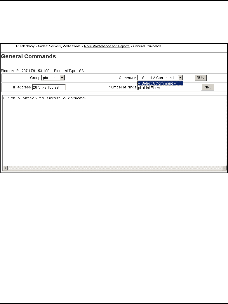
Features Page 197 of 910
IP Line Description, Installation and Maintenance
- pbxLink > Command - pbxLinkShow window to display the pbxLink
information. See Figure 42 on page 197.
Figure 42
pbxLinkShow in Element Manager
CLI
For a Meridian 1 or CS 1000 system, use the LD 117 STAT SERV command
at the Command Line Interface (CLI) of the Call Server to display the
pbxLink information.
LD 117 STAT SERV
The suite of STAT SERV (Statistic Services) commands enables a technician
to display link-status information for Voice Gateway Media Cards that are
registered to a Call Server.
STAT SERV can provide consolidated link-status information by application
type, IP address, host name, and IP Telephony Node ID.

Page 198 of 910 Features
553-3001-365 Standard 4.00 August 2005
STAT SERV status information includes the following:
• node ID
• host name
• ELAN IP address
• element role
• platform type
• connection ID
• enabled applications
• registered/unregistered endpoints, such as IP Phones and Voice Gateway
Media Cards.
• information about the pbxLink and enabled applications
• Signaling Server resource count
Note: The Signaling Server resource count aids in determining the
number of virtual trunks that can be configured.
pbxLink information
The STAT SERV command provides the following pbxLink information:
• the time the pbxLink was last established
• the time the pbxLink was lost, if previously established
• the time the pbxLink last attempted to establish a connection, if the
pbxLink failed to establish
• the Signaling Server resource count
Application information
If an active link to an element is established, the Call Server obtains
information about the applications running on the element.

Features Page 199 of 910
IP Line Description, Installation and Maintenance
Table 29 lists the applications and describes the information provided by
those applications.
Figure 43 on page 200 shows an example of LD 117 STAT SERV output.
Table 29
Queried information in STAT SERV
Application / element Information provided
LTPS application number of registered IP Phone
number of busy IP Phones
VTRK application number of registered VTRKs
number of busy VTRKs
Voice Gateway Media
Cards
number of registered Voice Gateway Media Cards
number of busy Voice Gateway Media Cards
Signaling Servers and
Voice Gateway Media
Cards
time that the element established its link with the Call Server
elements that failed to register or lost their link

Page 200 of 910 Features
553-3001-365 Standard 4.00 August 2005
Figure 43
Sample LD 117 STAT SERV output
Table 30 lists the descriptions for the fields in the STAT SERV response.
Table 30
STAT SERV response fields and description (Part 1 of 3)
STAT SERV response field Description
NODE ID Identifies the related node.
Value is a number from 0 – 9999.
HOSTNAME Identifies the alias that the host has been
given by the system.
Value is a string.
=> stat serv
NODE HOSTNAME ELANIP LDR SRV APPS PBXLINK
PBXLINK PBXLINK CONNECTID
ID STATE
DATE TIME
9090 host82 47.11.217.176 NO SMC LTPS LINK UP
28/07/2004 17:51:31 200a4048
Sets: [reg - 00000] [busy - 00000]
VGWs: [reg - 00032] [busy - 00000]
9090 host9 47.11.217.177 YES SS LTPS LINK UP
28/07/2004 17:51:33 200a3f68
VTRK
Sets: [reg - 00003] [busy - 00000]
VTRK: [reg - 00383] [busy - 00000]
SIGNALLING SERVER CAPACITY (SSRC): 2048
9090 itgCard 47.11.217.2 NO ITGP LTPS FAILED
28/07/2004 17:51:16 0

Features Page 201 of 910
IP Line Description, Installation and Maintenance
ELANIP Identifies the element’s IP connection to the
Call Server.
Value is an IP address.
LDR Specifies if the element is the Leader for the
related node.
Value is YES or NO.
SRV Specifies the element type.
Values are:
• SMC – Media Card 32-port card
• ITGP – ITG-P 24-port card
• SS – Signaling Server
APPS Specifies the application running on the
element.
Values are:
•LTPS
•VTRK
PBXLINK STATE Specifies the element’s current pbxLink state.
Values are:
•LINK UP
•LOST
•FAILED
• INV CONN (element is connected, but its
configuration was not found on the Call
Server, indicating that this element might
be connected to the wrong Call Server)
Table 30
STAT SERV response fields and description (Part 2 of 3)
STAT SERV response field Description

Page 202 of 910 Features
553-3001-365 Standard 4.00 August 2005
IP Phone support
The IP Line 4.5 application supports the following IP Phones:
• IP Phone 2001
• IP Phone 2002
• IP Phone 2004
• IP Phone 2007
PBXLINK DATE/TIME Specifies when the element’s pbxLink state
last changed.
CONNECTED Specifies the element’s connection ID.
Sets Values are:
• reg – the number of IP Phones registered
to the element
• busy – the number of IP Phones that are
currently busy
VGWs Values are:
• reg – how many voice gateways (DSP
resources) are configured on the element
• busy – how many voice gateways (DSP
resources) are active/busy on the element
VTRK Values are:
• reg – how many VTRK channels are
configured on the element
• busy – how many VTRK channels are
active/busy on the element
SSRC Signaling Server capacity
Table 30
STAT SERV response fields and description (Part 3 of 3)
STAT SERV response field Description

Features Page 203 of 910
IP Line Description, Installation and Maintenance
• IP Audio Conference Phone 2033
• IP Softphone 2050
• Mobile Voice Client (MVC) 2050
• WLAN Handset 2210
• WLAN Handset 2211
• WLAN Handset 2212
For detailed information about IP Phones, see the following:
•IP Phone 2001 User Guide
•IP Phone 2002 User Guide
•IP Phone 2004 User Guide
•IP Phone 2007 User Guide
•IP Audio Conference Phone 2033 User Guide
•IP Softphone 2050 User Guide
•Mobile Voice Client 2050 User Guide
•WLAN Handset 2210 User Guide
•WLAN Handset 2211 User Guide
•WLAN Handset 2212 User Guide
•WLAN IP Telephony: Installation and Configuration (553-3001-304)
•IP Phones: Description, Installation, and Operation (553-3001-368)

Page 204 of 910 Features
553-3001-365 Standard 4.00 August 2005
Table 31 describes the IP Phone 2001.
Table 31
IP Phone 2001
Feature IP Phone 2001 characteristic
Display
Display size and format 1 line display
24 characters
Information Line 1 line – 24 characters
Dedicated Date/Time field No
Context Label field No
Keys
Soft Keys 4 soft keys, soft-labeling
6 characters long
Feature Keys No
Other features
DHCP support Yes
Transducers Handset (HD)
Mute key No
Navigation keys Left and right
Voice codec support G.711, G729A, G729AB, G.723.1
Firmware download Automatic firmware version
checking and download
3-port unmanaged Layer 2 switch
for data and voice
No
Corporate Directory access No

Features Page 205 of 910
IP Line Description, Installation and Maintenance
Table 32 describes the IP Phone 2002.
Table 32
IP Phone 2002
Feature IP Phone 2002 characteristic
Display
Display size and format 1 line display
24 characters
Information Line 1 line – 24 characters
Dedicated Date/Time field No
Context Label field No
Keys
Soft Keys 4 soft keys, soft-labeling
6 characters long
Feature Keys 4 soft keys, soft-labeling
10 characters long
Other features
DHCP support Yes
Transducers Headset (HS) / Handset (HD) /
Handsfree (HF)
Mute key Yes
Navigation keys Up, down, left, and right
Voice codec support G.711, G729A, G729AB, G.723.1
Firmware download Automatic firmware version
checking and download
3-port unmanaged Layer 2 switch
for data and voice
Built-in
Corporate Directory access Yes

Page 206 of 910 Features
553-3001-365 Standard 4.00 August 2005
Table 33 describes the IP Phone 2004.
Table 33
IP Phone 2004 (Part 1 of 2)
Feature IP Phone 2004 characteristic
Display
Display size and format 3 line display
24 characters on each line
Information Line 3 lines – 24 characters on each line
Dedicated Date/Time field Yes
Context Label field Yes
Keys
Soft Keys 4 soft keys, soft-labeling
7 characters long
Feature Keys 6 soft keys, soft-labeling
10 characters long
Other features
DHCP support Yes
Transducers Headset (HS) / Handset (HD) /
Handsfree (HF)
Mute key Yes
Navigation keys Up, down, left, and right
Voice codec support G.711, G729A, G729AB, G.723.1
Firmware download Automatic firmware version checking
and download

Features Page 207 of 910
IP Line Description, Installation and Maintenance
Table 34 describes the IP Phone 2007.
3-port unmanaged Layer 2 switch
for data and voice
Built-in
Note: Earlier models have an
external switch.
Corporate Directory access Yes
Table 34
IP Phone 2007 (Part 1 of 2)
Feature IP Phone 2007 characteristic
Display
Display size and format Color touch panel
Stylus for clicking (no dragging)
2 display areas – application area
and tools/navigation area
3 line display in each area
24 characters on each line
Dedicated Date/Time field Yes
Context Label field Yes
Keys
Soft Keys 4 virtual soft keys, soft-labeling
7 characters long
2 actual softkeys, soft-labeling
(located on either side of the
Navigation key)
Table 33
IP Phone 2004 (Part 2 of 2)
Feature IP Phone 2004 characteristic

Page 208 of 910 Features
553-3001-365 Standard 4.00 August 2005
Feature Keys 6 virtual soft keys, soft-labeling
10 characters long
Other features
GUI screen Supports web-based (XML, HTML)
applications through an external
Applications Server
USB Single USB port and driver support
DHCP support Yes
Transducers Headset (HS) / Handset (HD) /
Handsfree (HF)
Mute key Yes
Navigation keys One key that rocks up, down, left,
and right
Voice codec support G.711, G729A, G729AB, G.723.1
Firmware download Automatic firmware version checking
and download
3-port unmanaged Layer 2 switch
for data and voice
Built-in
Corporate Directory access Yes
Table 34
IP Phone 2007 (Part 2 of 2)
Feature IP Phone 2007 characteristic

Features Page 209 of 910
IP Line Description, Installation and Maintenance
Table 35 describes the IP Audio Conference Phone 2033.
Table 35
IP Audio Conference Phone 2033
Feature
IP Audio Conference Phone 2033
characteristic
Display
Display size and format 1 line display
24 characters
Information Line 1 line – 24 characters
Dedicated Date/Time field No
Context Label field No
Keys
Soft Keys 3 soft keys which map to 4,
soft-labeling
6 characters long
Feature Keys No
Other features
DHCP support Yes
Transducers Handsfree (HF) – default
Mute key Yes
Navigation keys Up and down
Voice codec support G.711, G729A, G729AB
Firmware download Automatic firmware version
checking and download
3-port unmanaged Layer 2 switch
for data and voice
No
Corporate Directory access No

Page 210 of 910 Features
553-3001-365 Standard 4.00 August 2005
Table 36 lists the features of the WLAN Handsets 2210/2211/2212.
Table 36
WLAN Handset 2210/2211/2212 features
Feature WLAN Handset 2210 WLAN Handset 2211
Su[pported standard 802.11b (Wi-Fi) compatible 802.11b (Wi-Fi) compatible
Soft keys 4 dynamically labeled soft
keys
4 dynamically labeled soft
keys
Feature support Over 400 Nortel features Over 400 Nortel features
Alerting Tactile Tactile
Line capacity Maximum of 6 lines Maximum of 6 lines
Supported codecs G.711 (A- and µ-law), G.729
AB
G.711 (A- and µ-law), G.729
AB
Addressing DHCP or static IP DHCP or static IP
Battery capacity 4 hours talk, 70 hours
standby
4 hours talk, 70 hours
standby
Security WEP 40 bit and 128 bit
encryption, WPA w/TKIP,
WPA w/PSK
WEP 40 bit and 128 bit
encryption, WPA w/TKIP,
WPA w/PSK
Jacks headset jack Headset jack
Transmit RF power 100 mW peak, <10 mW
average
100 mW peak, <10 mW
average
Dimensions 5.5" x 2.0" x 0.9" 5.5" x 2.2" x 1.0"
Weight 4.2 ounces 6 ounces
Loudspeaker No Ye s
Push-to-talk No 8 independent push-to-talk
channels

Features Page 211 of 910
IP Line Description, Installation and Maintenance
IP Phone Key Expansion Module
IP Line 4.5 supports the Nortel IP Phone Key Expansion Module (KEM).
The IP Phone KEM is a hardware component that attaches to the IP Phone
2002 and IP Phone 2004 and provides additional line appearances and feature
keys.
Note: The IP Phone KEM is not supported on the IP Phone 2001,
IP Phone 2007, and IP Audio Conference Phone 2033.
Up to two IP Phone KEMs can be attached to an IP Phone 2002 or IP Phone
2004. With two IP Phone KEMs attached, the IP Phone 2004 can have up to
60 lines/feature keys, while the IP Phone 2002 can have up to 52 lines/feature
keys.
Note: The IP Phone 2004 can also have up to 60 lines/feature keys using
the shift key and one IP Phone KEM. With two IP Phone KEMs
attached, the shift key does not affect the IP Phone KEMs since the
maximum number of lines/feature keys is already available. The
IP Phone 2002 does not support shift key functionality.
When an IP Phone KEM is installed on an IP Phone 2002 or IP Phone 2004,
the controls on the IP Phone affect both the IP Phone itself and the IP Phone
KEM.
The IP Phone KEM must be configured in LD 11 before it can be used.
For information on using the IP Phone KEM, refer to IP Phone Key
Expansion Module User Guide.
Corporate Directory
The Corporate Directory feature is based on the M3900 telephone Corporate
Directory feature.

Page 212 of 910 Features
553-3001-365 Standard 4.00 August 2005
The Corporate Directory database is created using OTM 2.2 and is generated
from one of the following:
• the configured DN information from the Call Server
• the data from a corporate LDAP server
The database is downloaded and stored on the Call Server. It is then
accessible to the IP Phones. The Signaling Server can support Corporate
Directory access for the same number of IP Phones that are registered.
The Directory key on the IP Phone is used to access the directory, select a
listing, and then dial a number from the Corporate Directory. The Navigation
keys are used to refine the search within the Corporate Directory.
Corporate Directory is configured in LD 11. LD 11 accepts CRPA/CRPD
class of service for the IP Phones (see “Corporate Directory: LD 11
configuration” on page 533).
For more information about the operation of the Corporate Directory feature,
refer to the following:
•Optivity Telephony Manager: Installation and Configuration
(553-3001-230)
•IP Phones: Description, Installation, and Operation (553-3001-368).
Element Manager support
Element Manager enables configuration of IP Line 4.5 using a web browser
on CS 1000 systems.
Each Signaling Server hosts a web server, Element Manager, that allows
configuration, administration, and maintenance to be performed on the
system components. Element Manager is a graphical web interface that
provides a graphical alternative to the traditional CLI and overlays. The
interface is available to users running a web browser on a PC. No special
client software is required.
The Element Manager web server runs on each Signaling Server and the
Signaling Server acts as a file server.

Features Page 213 of 910
IP Line Description, Installation and Maintenance
When a web browser is opened and the IP address of the Signaling Server is
entered, the Element Manager interface is displayed. Element Manager is
then used to perform tasks such as configuring an IP Telephony Node,
checking and uploading loadware and firmware files, and retrieving the
CONFIG.INI and BOOTP.TAB configuration files from the Call Server. The
Voice Gateway Media Cards are notified to FTP the files from the Call
Server.
OTM 2.2’s Navigators incorporate links to each Element Manager web
server in a network.
BOOTP and CONFIG.INI
If the Voice Gateway Media Card is a Follower of a primary Signaling
Server, it generates a BOOTP request to retrieve its network information. The
request for IP address, node ID, and node IP is directed to a BOOTP server
within its node. If the BOOTP request fails, the Voice Gateway Media Card
uses the last configuration. This fallback configuration data is stored locally
on the Voice Gateway Media Card. If the BOOTP request is successful, the
Voice Gateway Media Card refreshes its current fallback configuration data.
If the Voice Gateway Media Card is located in a stand-alone IP Telephony
node, and is designated as the Leader for its node, it provides BOOTP service
to all other configured Voice Gateway Media Cards within its node. The
Leader determines its own network information using a combination of
locally stored static information and the bootp.tab file.
If the Voice Gateway Media Card is located in a stand-alone IP Telephony
node, and is designated as a Follower, it generates a BOOTP request to
retrieve its network information. The request for IP address, node ID, and
node IP is directed to a BOOTP server within its node. If the BOOTP request
fails, the Voice Gateway Media Card uses the last configuration. This
fallback configuration data is stored locally on the Voice Gateway Media
Card. If the BOOTP request is successful, the Voice Gateway Media Card
refreshes its current fallback configuration data.
The Voice Gateway Media Card reads the contents of the CONFIG.INI file
located on its disk for additional configuration parameters.

Page 214 of 910 Features
553-3001-365 Standard 4.00 August 2005
Call Statistics collection
IP Line 4.5 enables statistics on the Quality of Service (QoS) of calls
connected by the Call Server to be collected.
These commands print the number of IP Phones registered on a card, zone,
node, or Signaling Server. Traffic printouts are available per zone at
user-configurable intervals for the following:
• blocked calls
• bandwidth used
• call attempts and completions
Counting IP Phones
The commands to count registered IP Phones are available in LD 32 and
LD 117.
CS 1000 Release 4.5 introduces the following commands in LD 117:
• ECNT FW <XX> <A> <BB> <FF> – count the number of IP Phones
with specified firmware ID and, optionally, firmware version.
• ECNT MODL <MMMM> – count the number of IP Phones of the
specified model>. If the MMMM parameter is omitted, the IP Phone
Model Names and their associated mnemonics are listed.
• ECNT PEC <PEC> – count the number of IP Phones with a specified
Product Engineering Code (PEC).
Before CS 1000 Release 4.5, all ECNT commands were in LD 32. The
following existing LD 32 ECNT commands are now duplicated in LD 117 to
maintain a consistent interface. However, they continue to be maintained in
LD 32 as well.
• ECNT CARD <Loop> <Shelf> <Card> <CustomerNumber>
• ECNT NODE <NodeNumber>
• ECNT SS <HostName>
• ECNT ZONE <ZoneNumber> <CustomerNumber>

Features Page 215 of 910
IP Line Description, Installation and Maintenance
Table 37 describes these commands.
Table 37
LD 117 commands to count registered IP Phones (Part 1 of 4)
Command Description
ECNT CARD L S C
<customer>
Counts and prints the number of IP Phones registered for the specified
card.
• If the <customer> parameter is specified, the count is specific to that
customer. A card must be specified to enter a customer; otherwise,
the count is across all customers.
• If no parameters are entered, the count is printed for all zones. A
partial TN can be entered for the card (L or L S) which then prints the
count per that parameter. A customer cannot be specified in this
case.
Example:
ECNT CARD 81
<< Card 81 >>
Number of Registered Ethersets: 5
Number of Unregistered Ethersets: 27
ECNT ZONE
zoneNum
<customer>
Counts and prints the number of IP Phones registered for the specified
zone.
• If <customer> parameter is specified, the count is specific to that
customer. A zone must be specified to enter a customer; otherwise,
the count is across all customers.
• If no parameters are entered, the count is printed for all zones.
Example:
ECNT ZONE 0 0
<< Zone 0 Customer 0 >>
Number of Registered Ethersets: 4
Number of Unregistered Ethersets: 17

Page 216 of 910 Features
553-3001-365 Standard 4.00 August 2005
ECNT NODE
nodeNum
Counts and prints the number of IP Phones registered for the specified
node.
• If the nodeNum parameter is not entered, the count is printed for all
nodes.
Example:
ECNT NODE 8765
<< Zone 8765 >>
Number of Registered Ethersets: 3
ECNT SS
<hostName>
Counts and prints the number of IP Phones registered for the specified
Signaling Server.
• If hostName parameter is not entered, the count is printed for all
Signaling Servers.
Example:
ECNT SS
<< Signaling Server: BVWAlphaFox IP 10.10.10.242>>
Number of Register Ethersets: 1000
Note: If the hostName variable contains an underscore (_), then an
NPR001 error message is returned, as an underscore is considered to
be an invalid character.
Table 37
LD 117 commands to count registered IP Phones (Part 2 of 4)
Command Description

Features Page 217 of 910
IP Line Description, Installation and Maintenance
ECNT FW <XX>
<A> <BB> <FF>
Prints the number of IP Phones with specified firmware ID and running
specified firmware version.
<XX> – firmware ID
<A> – major version designator
<BB> – minor version designator
<FF> – filter to apply on firmware version; can be one of the following:
= – equal to
~ – not equal to
< – less then
> – greater then
Only the XX parameter is mandatory.
ECNT FW <XX> <A> <BB> defaults to
ECNT FW <XX> <A> <BB> =
ECNT FW <XX> <A> counts all registered IP Phones with firmware ID
equal to <XX> and major version designator equal to <A>.
ECNT FW <XX> counts all registered IP Phones with firmware ID equal
to <XX>.
ECNT FW is equivalent to ECNT FW ALL; that is, the list containing
firmware IDs and the quantity of IP Phones with this firmware ID is
printed.
ECNT MODL
<MMMM>
Prints the number of IP Phones of specified model.
<MMMM> – specifies model name.
If this parameter is omitted, then a list of the model names and
associated mnemonics is printed.
Table 37
LD 117 commands to count registered IP Phones (Part 3 of 4)
Command Description

Page 218 of 910 Features
553-3001-365 Standard 4.00 August 2005
Error messages for the ECNT commands
Error messages are printed when invalid data is entered for these commands.
The messages include valuable information such as the correct ranges for the
command parameters. See the following tables for the error messages:
• Table 38: “ECNT Card command error messages” on page 218.
• Table 39: “ECNT Zone command error messages” on page 219.
• Table 40: “ECNT Node command error messages” on page 219.
• Table 41: “ECNT SS command error message” on page 220.
ECNT PEC <PEC> Prints the number of IP Phones with specified PEC, where:
<PEC> – Product Engineering Code
ECNT PEC is equivalent to ECNT PEC ALL; that is, the list containing
the PECs and the quantity of IP Phones with this PEC is printed.
Table 38
ECNT Card command error messages (Part 1 of 2)
Error Error Message
Slot out of range error Slot out of range. Range: [61-99]
Slot non-virtual loop error Slot does not correspond to a virtual
loop.
Slot not configured loop error Slot corresponds to a virtual loop but it is
not configured.
Customer out of range error Customer out of range. Range: [0-31]
Table 37
LD 117 commands to count registered IP Phones (Part 4 of 4)
Command Description

Features Page 219 of 910
IP Line Description, Installation and Maintenance
Customer not configured error Customer does not exist.
Combination of invalid slot and
invalid customer
Slot does not correspond to a virtual
loop.
Customer out of range. Range: [0-31]
Table 39
ECNT Zone command error messages
Error Error Message
Zone out of range error Zone out of range. Range: [0-255]
Zone not configured error Zone not configured.
Customer out of range error Customer out of range. Range: [0-31]
Customer not configured error Customer does not exist.
Combination of invalid zone
and invalid customer error
Zone not configured.
Customer out of range. Range: [0-31]
Table 40
ECNT Node command error messages
Error Error Message
Node out of range error Node out of range. Range: [0-9999]
Node not configured error Node not registered.
Table 38
ECNT Card command error messages (Part 2 of 2)
Error Error Message

Page 220 of 910 Features
553-3001-365 Standard 4.00 August 2005
IP Phone Zone Traffic Report 16
A system traffic report, IP Phone Zone Traffic Report 16 in LD 2 is created
on the system to print IP Phone data at the zone level. The data is printed for
the following categories at the end of each collection period on a per-zone
basis:
• Total inter/intra-zone calls made
• Total inter/intra zone calls blocked
• Percent average inter/intra zone bandwidth used
• Percent maximum inter/intra zone bandwidth used
• Total inter/intra zone bandwidth threshold exceeded count
The counters are reset after the data is printed.
The “Total inter/intra zone bandwidth threshold exceeded count” prints the
number of times a user-configured bandwidth threshold was exceeded for the
zone during the collection period. LD 2 commands that are related to setting
the system threshold are used with a value defined for the bandwidth
threshold.
Table 41
ECNT SS command error message
Error Error Message
SS not found in system error Signaling Server <name> does not exist.
Table 42
System threshold commands (Part 1 of 2)
Command Description
TTHS TH tv Prints the current system thresholds.

Features Page 221 of 910
IP Line Description, Installation and Maintenance
The following examples first set the system bandwidth to 75% and then print
the actual value.
.STHS 5 750
.TTHS 5
Table 43 describes the intrazone IP Phone Zone Traffic Report 16 output
data.
STHS TH tv -- TV Sets the system thresholds.
Note 1: A TH value of 5 is used for the zone bandwidth threshold.
Note 2: The system thresholds TV value is the percentage of the zone’s
maximum bandwidth. The range values are 000 – 999, where 000
corresponds to 00.0% and 999 corresponds to 99.9%. The default is
90.0%.
Table 43
IP Phone Zone Traffic Report 16 intrazone data output (Part 1 of 2)
Data Description
zone number of the zone
cmi intrazone calls made (successful)
cbi intrazone calls blocked
pi intrazone peak bandwidth (%)
ai intrazone average bandwidth usage (%)
vi intrazone bandwidth usage threshold violations
cul counts of unacceptable latency samples
cupl counts of unacceptable packet loss
cuj counts of unacceptable jitter samples
Table 42
System threshold commands (Part 2 of 2)
Command Description

Page 222 of 910 Features
553-3001-365 Standard 4.00 August 2005
Table 44 describes the interzone IP Phone Zone Traffic Report 16 output
data.
cur counts of unacceptable R factor samples
cuerl counts of unacceptable Echo Return Loss
cwl counts of warning latency samples
cwj counts of warning jitter samples
cwpl counts of warning packet loss samples
cwr counts of warning R factor samples
cwerl counts of warning Echo return Loss
cmip counts of measuring interval samples
Table 44
IP Phone Zone Traffic Report 16 interzone data output (Part 1 of 2)
Data Description
zone number of the zone
cmo interzone calls made
cbo interzone calls blocked
po interzone peak bandwidth (%)
ao interzone average bandwidth usage (%)
vo interzone bandwidth usage threshold violations
cwpl counts of warning packet loss
cwl counts of warning latency samples
cwj counts of warning jitter samples
Table 43
IP Phone Zone Traffic Report 16 intrazone data output (Part 2 of 2)
Data Description

Features Page 223 of 910
IP Line Description, Installation and Maintenance
The following is an example of the output from Traffic Report 16.
>ld 2
TFC000
.invs 16
0000 TFS016
ZONE 003
INTRAZONE 00005 00000 00002 00000 00000 00051 00000 00020
00000 00000 00000 00000 00000 00000 00000 00000
INTERZONE 00003 00000 00007 00006 00000 00006 00000 00006
00000 00000 00000 00000 00000 00000 00000 00000
ZONE 006
INTRAZONE 00008 00000 00001 00000 00000 00050 00000 00048
00001 00000 00000 00000 00000 00002 00025 00000
INTERZONE 00003 00000 00007 00006 00000 00007 00000 00007
00001 00000 00000 00000 00000 00000 00007 00000
cupl counts of unacceptable packet loss
cul counts of unacceptable latency samples
cuj counts of unacceptable jitter samples
cur counts of unacceptable R factor samples
cuerl counts of unacceptable Echo Return Loss
cwr counts of warning R factor samples
cwerl counts of warning Echo Return Loss
cmip counts of interval measuring samples
Table 44
IP Phone Zone Traffic Report 16 interzone data output (Part 2 of 2)
Data Description

Page 224 of 910 Features
553-3001-365 Standard 4.00 August 2005
All other commands (SOPS, COPS, TOPS) function in the normal manner.
Table 45 shows the SOPS, COPS, and TOPS commands:
User-defined feature key labels
Definition
IP Line 4.5 lets the IP Phone user program the label on the feature key. This
label change is saved and then displayed on the feature key.
Availability
Table 46 describes the feature key availability on the IP Phones.
Table 45
SOPS, COPS, TOPS commands
.tops 1 2 3 4 5 14 display the current system report
list
.sops 1 2 3 4 5 14 -- 16 add report 16 to be printed
.tops 1 2 3 4 5 14 16 display system report list with
report 16 added
.cops 1 2 3 4 5 14 16 -- 16 delete report 16
.tops 1 2 3 4 5 14 display system report list with
report 16 deleted
Table 46
Feature key availability on IP Phones (Part 1 of 2)
Model
Number of feature
keys
Number of feature
keys using Shift
key
Maximum label
character length
IP Phone 2002 4 N/A 10
IP Phone 2004 612 10

Features Page 225 of 910
IP Line Description, Installation and Maintenance
Note: There are no feature keys on the IP Phone 2001.
The feature key labels for each IP Phonee are stored in the Call Server’s
database. When the Call Server performs an EDD, the feature key labels are
saved to the database. The feature key label information is retrieved from the
file into memory during the sysload of the Call Server. When the system
performs an INI or sysload, feature key label changes performed by users
between the last EDD and the INI or sysload are lost.
When the IP Phone registers with the Call Server, the Call Server looks up the
feature key label in the memory, based on the TN of the IP Phone. If the labels
are found, they are sent to the IP Phone when the key map download occurs.
If the labels are not found, the Call Server sends out the key number strings
or key functions.
For more information about programmable line (DN)/feature keys
(self-labeled), refer to IP Phones: Description, Installation, and Operation
(553-3001-368).
Private Zone configuration
Private Zones are available for the CS 1000 and Meridian 1 systems.
Lack of DSP resources
DSP resources for each customer are placed in one common pool. A DSP
channel is allocated to an IP-to-circuit-switched call based on a round-robin
searching algorithm within the pool.
IP Softphone 2050 612 10
MVC 2050 612 10
Table 46
Feature key availability on IP Phones (Part 2 of 2)
Model
Number of feature
keys
Number of feature
keys using Shift
key
Maximum label
character length

Page 226 of 910 Features
553-3001-365 Standard 4.00 August 2005
If an available resource cannot be found, the overflow tone is given. For most
installations, this approach works because all IP Phone users share the IP Line
DSP resources. The DSPs can be provisioned using a DSP-to-IP Phone ratio
similar to trunk resources, since the DSPs are used only for circuit-switched
access or conference calls.
When IP-to-PSTN calls are used, such as with ACD agents or other users who
consistently are using trunk resources when making calls, it becomes difficult
to provision the system in a way that guarantees an available DSP channel
when these users need it. If the other users suddenly make a lot of conference
calls or trunk calls, the DSP resources can deplete and as a result, calls cannot
be made. This occurs because all DSP channels are in one pool.
DSP resources and Private Zones
To address this situation, IP Line 4.5 provides the Private Zone Configuration
feature for DSP configuration and allocation to the zone configuration. This
feature enables the configuration of one or more gateway channels as a
private resource. This guarantees DSP availability for critical or ACD agent
IP Phone.
A zone can be configured as shared or private.
Shared Zone
The current default zone type is a Shared Zone. IP Phones configured in
Shared Zones use DSP resources configured in shared zones. If all the Shared
Zones’ gateway channels are used, the caller receives an overflow tone and
the call is blocked.
Select gateway channels in the following order:
• Select a channel from the same zone as the zone where the IP Phone is
configured.
• Select any available channel from the Shared Zones’ channels.
Private Zone
The Private Zone enables DSP channels configured in a Private Zone to be
used only by the IP Phones that have also been configured for that Private

Features Page 227 of 910
IP Line Description, Installation and Maintenance
Zone. If more DSP resources are required by these IP Phones than what are
available in the zone, DSPs from other Shared Zones are used.
IP Phones configured in Shared Zones cannot use the Private Zones’
channels.
Select the gateway channels in the following order:
• Select a channel from the same Private Zone as the zone where the IP
Phone is configured.
• Select any available channel from the pool of Shared Zones’ channels.
LD 117
VGW channels and IP Phones are set as shared or private based on zone
configuration. In LD 117, zone configuration can be set to either shared or
private using the parameter <zoneResourceType>.
A zone is configured in LD 117 as follows:
NEW ZONE <zoneNumber> [<intraZoneBandwidth>
<intraZoneStrategy> <interZoneBandwidth> <interZoneStrategy>
<zoneResourceType>]
CHG ZONE <zoneNumber> [<intraZoneBandwidth>
<intraZoneStrategy> <interZoneBandwidth> <interZoneStrategy>
<zoneResourceType>]
By default, a zone is configured as shared (zoneResourceType=shared).
Example
The command to add a new zone, in this example zone 10, is as follows:
new zone 4 BQ 10000 BQ 10000 private
Zone 4 added. Total number of Zones = n
(where n is the total number of zones)

Page 228 of 910 Features
553-3001-365 Standard 4.00 August 2005
Site details
Use the PRT ZONE or PRT ZONE ALL command to see details for all
configured zones. Table 47 gives a sample output of the PRT ZONE or PRT
ZONE ALL command.
Resource-sharing for Shared and Private Zones
If a resource-critical IP Phone is configured for a Private Zone, and there are
not enough resources found within that zone, the search continues into the
Shared Zones within the same customer for an available DSP channel.
However, if an IP Phone is configured in a Shared Zone, the Call Server limits
its search to the pool of shared DSP channels. The search does not extend into
the Private Zones’ channels.
Table 47
Sample output from PRT ZONE or PRT ZONE ALL command
Intrazone Interzone
Zone State Typ e Bandwidth
(Kbps)
Strategy Usage
(%)
Peak
(Kbps)
Bandwidth
(Kbps)
Strategy Usage
(%)
Peak
(Kbps)
HO/BRCH
0ENL SHARED 100000 BQ 0 0 100000 BQ 0 0 HO
1ENL SHARED 10000 BQ 0 0 10000 BQ 0 0 HO
4ENL PRIVATE 10000 BQ 0 0 10000 BQ 0 0 HO
10 ENL SHARED 10000 BQ 0 0 10000 BQ 0 0 HO

Features Page 229 of 910
IP Line Description, Installation and Maintenance
When configuring the allocation of shared versus private resources,
consideration must be given to the number of private resources that are
needed. Enough DSP resources should be configured to prevent the IP Phones
configured in Shared Zones from running out of channels.
Run-time configuration changes
IP Line 4.5 enables most changes to be made without disabling or rebooting
the Voice Gateway Media Cards. After adding configuration information for
a new Voice Gateway Media Card and downloading the BOOTP file to the
Leader, a new Voice Gateway Media Card can be added to an existing node
without rebooting the other cards.
The following exceptions require a reboot:
• a role change; that is, changing a Leader to Follower or changing
Follower to Leader.
• changing the node IP subnet masks or gateway IP addresses requires a
reboot of all cards in the node.
• changing the AudioPort parameter in the “config.ini” file on the Voice
Gateway Media Card requires a reboot of the card
• changing the IP address of a particular card so it can retrieve its new IP
address information.
WARNING
The Call Server does not search for voice gateway
channels in Private Zones when the IP Phone is
configured in a Shared Zone. Only IP Phones configured
in the same Private Zone can use the Private Zone voice
gateway channels.
Since the voice gateway channels in the Private Zone
are not accessible to IP Phones in the Shared Zone,
ensure that only enough private channels are configured
to cover the IP Phones in the Private Zone. Do not
configure more channels than are required in the Private
Zone as the Shared Zone IP Phones cannot access
these channels.

Page 230 of 910 Features
553-3001-365 Standard 4.00 August 2005
Supported run-time changes
Therefore, IP Line 4.5 supports only run-time changes for the following:
• changes to the CONFIG.INI file
• add card or delete card changes to the BOOTP.TAB file
Configuration changes have an effect only on new calls. Existing calls are not
interrupted. However, there are exceptions:
• If the active Call Server ELAN link’s configuration data is changed (for
example, a changed IP address), then active calls are released.
Note: If the non-active Call Server is changed (for example, survivable
side IP address), then the calls are not affected.
When the Call Server’s ELAN network interface is re-initialized to
implement the configuration change, the IP Phones and gateway
channels registrations are unregistered on the Call Server. The Call
Server releases the calls. When the link is re-established, the LTPS
synchronizes the call states and releases the active calls. Service is
interrupted during this re-establishment period and the following are
affected:
— New IP Phones cannot register.
— Registered IP Phones cannot establish new calls.
— The Voice Gateway Media Card’s faceplate displays S009.
Once the ELAN link comes back up, the Line Terminal Proxy Server
(LTPS) reregisters the IP Phone s with the Call Server and all service is
resumed.
• If the codec list is changed, the Voice Gateway Media Card's DSPs might
need to be reloaded. For instance, one DSP image contains G.711, FAX,
and G.729A/G.729AB. The other DSP image contains G.711, FAX, and
G.723.1. If the user has a node configured with the G.729AB codec and
the user performs an administrative change to use G.723.1 (or vice
versa), the DSPs must be reloaded.
After the CONFIG.INI file containing the administrative change is
downloaded to a Voice Gateway Media Card, the card's DSPs are

Features Page 231 of 910
IP Line Description, Installation and Maintenance
reloaded as they become idle. For instance, if all DSPs are idle on the
card, the new image is loaded to all of them at once. If one or more DSPs
have active calls, the DSP is not reloaded until the active calls have been
released. This can cause some DSPs to be reloaded later than others.
This functionality is supported by both Element Manager and OTM 2.2.
Network wide Virtual Office
Network Wide Virtual Office is supported for the CS 1000 systems.
IP Line 4.5 provides the Network Wide Virtual Office feature. This feature
enables a user to use any IP Phone within the network.
The Virtual Office feature provides a call service to “travelling” users who
want to use a different physical IP Phone (other than the IP Phone they
normally use). Users can log into another IP Phone using their DN and
pre-configured Station Control Password (SCPW).
Once logged in, users have access to their DNs, autodial numbers, key layout,
feature keys, and voice mail indication/access that are configured on their
own home/office IP Phones. For example, if users go to another office or to a
different location within the same office, they can log into any available
IP Phone and have all the features of their home/office IP Phone. When the
user logs off the IP Phone, the features that were “transferred” to that
IP Phone are removed.
Network Wide Virtual Office and the Gatekeeper
Network Wide Virtual Office is limited to a single Gatekeeper zone. As long
as Virtual Offices share the same Gatekeeper, a Virtual Office login can
redirect an IP Phone to any of the systems.
Requirements
A Signaling Server or stand-alone gatekeeper is required in the network.

Page 232 of 910 Features
553-3001-365 Standard 4.00 August 2005
Supported IP Phones
Virtual Office is supported for the IP Phone 2001, IP Phone 2002 and
IP Phone 2004, the IP Softphone 2050, and the MVC 2050. An IP Phone
2004, IP Softphone 2050, or MVC 2050 users can log in from an IP Phone
2002 under certain conditions. See “Set type checking and blocking” on
page 249.
Table 48 shows which users can log in to particular IP Phones.
Table 48
Virtual Office login from various IP Phones (Part 1 of 3)
IP Phone User Virtual Office login
An IP Phone 2001
user...
... can Virtual Office log in from another IP Phone 2001, an IP Phone
2002, an IP Phone 2004, an IP Phone 2007, an IP Audio Conference
Phone 2033, an IP Softphone 2050, an MVC 2050, and a WLAN
Handset /2211/2212.
An IP Phone 2002
user...
...can Virtual Office log-in from another IP Phone 2002, an IP Phone
2004, an IP Phone 2007, an IP Softphone 2050, an MVC 2050, and a
WLAN Handset 2210/2211/2212.
... can log in under certain conditions when the user attempts a Virtual
Office login from an IP Phone 2001 and IP Audio Conference Phone
2033. See “Set type checking and blocking” on page 249.
An IP Phone 2004
user...
...can Virtual Office log in from another IP Phone 2004, an IP Phone
2007, an IP Softphone 2050, an MVC 2050, and a WLAN Handset
2210/2211/2212.
...can log in under certain conditions when the user attempts a Virtual
Office login from an IP Phone 2001, IP Phone 2002, and IP Audio
Conference Phone 2033. See “Set type checking and blocking” on
page 249.

Features Page 233 of 910
IP Line Description, Installation and Maintenance
An IP Phone 2007
user...
...can Virtual Office log in from another IP Phone 2007, an IP Phone
2004, an IP Phone 2007, an IP Softphone 2050, an MVC 2050, and a
WLAN Handset 2210/2211/2212.
...can log in under certain conditions when the user attempts a Virtual
Office login from an IP Phone 2001, IP Phone 2002, and IP Audio
Conference Phone 2033. See “Set type checking and blocking” on
page 249.
An IP Audio
Conference Phone
2033 user…
... can Virtual Office log in from another IP Audio Conference Phone
2033, an IP Phone 2001, an IP Phone 2002, an IP Phone 2004, an IP
Phone 2007, and a WLAN Handset 2210/2211/2212. See “Set type
checking and blocking” on page 249.
An IP Softphone
2050 user...
...can virtually log in from an IP Phone 2004, an IP Phone 2007, another
IP Softphone 2050, an MVC 2050, and a WLAN Handset
2210/2211/2212.
...can log in under certain conditions when the user attempts a Virtual
Office login from IP Phone 2002. See “Set type checking and blocking”
on page 249.
Note: Virtual login for an IP Softphone 2050 user to an IP Phone 2001
or an IP Audio Conference Phone 2033 is blocked.
An MVC 2050
user...
...can virtually login from another MVC 2050, an IP Phone 2004, an IP
Phone 2007, an IP Softphone 2050, and a WLAN Handset
2210/2211/2212.
...can log in under certain conditions when the user attempts a Virtual
Office login from an IP Phone 2002. See “Set type checking and
blocking” on page 249.
Note: Virtual login for an MVC 2050 user to an IP Phone 2001 or an IP
Audio Conference Phone 2033 is blocked.
Table 48
Virtual Office login from various IP Phones (Part 2 of 3)
IP Phone User Virtual Office login

Page 234 of 910 Features
553-3001-365 Standard 4.00 August 2005
Virtual Office User Allowed (VOUA) and Virtual Office Login Allowed
(VOLA) must be configured on the IP Phones as follows:
• The IP Phone where the user wants to virtually login (destination) must
have Virtual Office User Allowed (VOUA) configured.
• The IP Phone where the user wants to log in from (source) must have
Virtual Office Login Allowed (VOLA) configured.
Failed password attempt
Three failed password attempts to log in using the Virtual Office feature locks
the user out from Virtual Office login at the Call Server for one hour. The Call
Server lock can be removed by an administrator using an LD 32 command to
disable and re-enable that TN. Refer to Communication Server 1000M and
Meridian 1: Large System Maintenance (553-3021-500), Communication
Server 1000S: Maintenance (553-3031-500), or Software Input/Output:
Maintenance (553-3001-511) for more information.
Passwords and IP Phone Registration
An IP Phone registers using the TN (in its EEPROM). A valid user ID and
password are used to determine the Home LTPS for the IP Phone during the
Virtual Office connection. A Gatekeeper is required if the Home LTPS is not
the LTPS where the IP Phone is registered when the Virtual Office login is
initiated.
A WLAN Handset
2210/2211/2212
user...
...can Virtual Office log in from IP Phone 2004, an IP Phone 2007, an IP
Softphone 2050, an MVC 2050, and another WLAN Handset
2210/2211/2212.
...can log in under certain conditions when the user attempts a Virtual
Office login from an IP Phone 2001, IP Phone 2002, and IP Audio
Conference Phone 2033. See “Set type checking and blocking” on
page 249.
Table 48
Virtual Office login from various IP Phones (Part 3 of 3)
IP Phone User Virtual Office login

Features Page 235 of 910
IP Line Description, Installation and Maintenance
Virtual Office capabilities
Virtual Offices provides the following capabilities:
1A network-wide connection server (Gatekeeper) is equipped to provide
addressing information of call servers, based on a user’s DN.
2A key sequence is entered at an IP Phone to initiate the login sequence.
Then the current network DN and a user-level password is entered. The
password is the Station Control Password configured in LD 11. If a
SCPW is not configured, the Virtual Office feature is blocked.
3A user logs out when leaving the location.
For more detailed information about Virtual Office, see IP Phones:
Description, Installation, and Operation (553-3001-368).
Branch Office and Media Gateway 1000B
The Media Gateway 1000B (MG 1000B) provides a means of extending
CS 1000 Release 4.5 features to one or more remotely-located branch offices
using the Branch Office feature. A branch office is a remote location in the
network where IP Phones, PSTN access, and TDM telephones are located.
Definition
Branch Office is a feature set of the equipment and software that a secondary
location needs to centralize the call processing of its IP-based
communications network. The Call Server at the main office provides the call
processing for the IP Phones in both the main office and the MG 1000B in the
branch office location. The MG 1000B in the branch office location provides
access to the local PSTN.
Connections
The MG 1000B is connected to the main office over virtual trunks on a WAN
or LAN. IP Phone calls and IP network connections are controlled by, and
come from, the main office. If the main office fails to function, or a network
outage occurs, the Small System Controller (SSC) in the MG 1000B provides
service to the IP Phones located in the branch office location. The IP Phones
then survive an outage between the MG 1000B and the main office.

Page 236 of 910 Features
553-3001-365 Standard 4.00 August 2005
Components
The basic hardware of an MG 1000B includes the Media Gateway and the
Signaling Server. The Media Gateway provides access to the local PSTN for
users in the branch office location. It also provides support for analog devices
such as fax machines or telephones in the branch office location.
For detailed information about MG 1000B, refer to Branch Office:
Installation and Configuration (553-3001-214).
802.1Q support
The IP Phone 2001, IP Phone 2002, IP Phone 2004, IP Phone 2007 and IP
Audio Conference Phone 2033 support 802.1Q. The IP Softphone 2050
supports 802.1Q through the PC’s operating system. This support enables the
definition of virtual LANs (VLANs) within a single LAN. This improves
bandwidth management, limits the impact of broadcast and multicast
messages, and simplifies VLAN configuration and packet prioritization. A
higher level of security between network segments can be achieved.
Configuration of 802.1Q on IP Phones
The 802.1Q support for the IP Phones is configured and controlled using the
IP Phone’s user interface or DHCP. The DHCP approach eliminates the need
to manually configure the VLAN ID during the installation.
To configure 802.1Q, configure the following:
• “p” bits
• VLAN ID

Features Page 237 of 910
IP Line Description, Installation and Maintenance
Configure the “p” bits
By default, the 3-bit field “p” bits are set to 110b (6), which is the value
recommended by Nortel. The “p” bit value can be changed using either OTM
or Element Manager. Two fields in OTM 2.2 and Element Manager are used
to set the “p” bits:
1A check box that, when selected, means the priority bits should be set to
the value specified by the 802.1Q priority bit value field. If the check box
is unselected, the IP Phone sends out the default priority of 6.
2A 802.1Q priority bit value field. This field sets the value that the IP
Phones sends out. The range is 0 – 7.
Configure the VOICE and DATA VLAN ID
The VOICE VLAN ID and DATA VLAN ID fields can be specified on a “per
interface” basis and are global settings. This means that all voice packets
transmitted by the IP Phone have the same VOICE VLAN ID and all data
packets have the same DATA VLAN ID. Though there is only one network
interface on the IP Phone, the IP Phone has two internal IDs: one for voice
traffic and one for data traffic. The IP Phone firmware can detect and route
the voice and data traffic.
Note: If a DATA VLAN is enabled, the IP Phone adds the DATA
VLAN ID to untagged traffic. However, if the traffic arriving on the PC
port is already tagged, the frame passes through unchanged.
The VLAN ID is specified as follows:
• The default VLAN ID is 000 (hex).
• The VOICE and DATA VLAN ID can be specified during a manual
configuration of the IP Phone using the IP Phone keypad, or
automatically retrieved using DHCP (automatic VLAN discovery).
• In the case of the VOICE VLAN ID, the VOICE VLAN ID can also be
configured by the DHCP parameter when using the Automatic VLAN ID
configuration using DHCP approach.
Note: For more information about manual or automatic IP Phone
configuration, refer to IP Phones: Description, Installation, and
Operation (553-3001-368).

Page 238 of 910 Features
553-3001-365 Standard 4.00 August 2005
The following describes the IP Phone support for 802.1Q.
DHCP requirements
Some implementation requirements of the Automatic VLAN Discovery using
DHCP are:
1A DHCP server IP address pool must exist for each subnet (also
VLANs). This is standard DHCP operation. The requirement is the same
for PCs or IP Phones.
2A DHCP server should not exist in more than one VLAN at one time (one
subnet for each VLAN), unless the link to the DHCP server is tagged and
the DHCP server can recognize this. With an untagged link to the DHCP
server, traffic could originate on one VLAN and end up on the other
VLAN. In this case, the VLAN using DHCP feature does not work.
Step Action
1If 802.1Q is disabled, standard Ethernet frames are transmitted.
2If 802.1Q is enabled, all frames transmitted by the Ethernet driver have the 802.1Q tag
bytes inserted between the source MAC address and the protocol type field. The tag
protocol identifier field contains 8100 (hex) and the CFI bit is set to 0.
3When 802.1Q is enabled, separate voice and data VLANs can be configured. Each
VLAN has its own ID and priority on the IP Phone. Voice packets have the priority bits
of all frames set to 6 (octal) and the VOICE VLAN ID is set to 000 (hex) by default. Data
packets have the priority bits of all frames set to 0 and the DATA VLAN ID is set to 000
(hex) by default. The GUI and TPS configured values override these values.
4The IP Phone’s Ethernet driver receives any Ethernet frame destined for it, regardless
of whether 802.1Q is enabled or the received frame is an 802.1Q tagged frame.
Note: The only exception is any 802.1Q tagged frame with CFI = 1. In this case, the
frame is discarded.
5The IP Phone’s Ethernet driver strips the 802.1Q tag information from the frame before
passing it on to the IP stack.
6The IP Phone’s Ethernet driver filters the packets by the VLAN tag and MAC address.
Tagged traffic is prioritized and routed based on the priority bits.

Features Page 239 of 910
IP Line Description, Installation and Maintenance
3Voice and data subnets must be separate if the three-port switch with
VLANs is being used.
4A Layer 3 switch (or router) with a relay agent must be used because
traffic from the voice VLAN to the data VLAN must be routed.
Presumably, the DHCP server is on the data VLAN. Without a relay
agent, a DHCP server must exist on each subnet.
5At least two IP address pools are used on the DHCP server – one for the
Voice VLAN/subnet and another for the Data VLAN/subnet. Additional
pools can be added as required as long as one IP address pool per subnet
and VLAN is used. A relay agent is required if it is a PC-only network.
Control of the IP Phone’s 802.1Q
The 802.1Q header in the outgoing packets from the IP Phones is enabled by
one of the following:
• If the IP Phone’s VLAN GUI response is set to 1, then the 802.1Q
functionality is enabled. All packets from the IP Phone have the 802.1Q
header as part of the Ethernet frame.
• If the IP Phone’s VLAN GUI response is set to 2, then the 802.1Q
functionality is enabled after the DHCP response is received with the
VLAN ID.
• If the OTM or Element Manager configuration enables the use of the “p”
bits, once downloaded to the IP Phone, the 802.1Q functionality is
enabled.
802.1Q and the Voice Gateway Media Cards
The ITG-P 24-port and Media Card line cards cannot send the 802.1Q header
because the cards’ operating system does not support it. The switch ports
connecting the Voice Gateway Media Card’s TLAN network interface should
be configured for untagged operation so if a 802.1Q header is present, it is
stripped before a packet is passed to the card.
The configuration in OTM and Element Manager is for the control of the
priority bits in the 802.1Q header sent by the IP Phones only.

Page 240 of 910 Features
553-3001-365 Standard 4.00 August 2005
Three-port switch support
The IP Phone three-port switch does not interpret the 802.1Q header. Instead,
the three-port switch allows the packets to pass through unmodified. Packet
priority is achieved on a per-port basis. IP Phone port traffic has a higher
priority than traffic for the Ethernet port to which the PC is connected.
An IP Phone can receive broadcast frames from a PC’s data VLAN. Any
broadcast storm packets from the data network are seen by the IP Phone.
However, this type of traffic does not adversely affect the IP Phone.
Data Path Capture tool
IP Line 4.5 contains the Data Path Capture tool, a built-in utility used to
capture audio information. This tool helps debug audio-related gateway
problems and allows after-the-fact analysis of what the user heard.
The Data Path Capture process is controlled by a set of CLI commands.
IP Phone firmware
Minimum firmware version
Refer to the ReadmeFirst documentation to determine the IP Phone minimum
firmware (F/W) versions supported by IP Line 4.5.
Firmware download
The firmware files for the IP Phones are downloaded from OTM 2.2 or
Element Manager to the node Master. They are compressed as they are stored
on the node Master card’s /C: drive. File compression reduces the firmware
file to less than 900 K. However, the /C: drive Flash disk space is limited on
the ITG-P 24-port line card.
The IP Phone normally does not have to be pre-loaded with the firmware file
because, during normal operation, the IP Phone’s firmware is automatically
upgraded as part of the registration to the LTPS. If the firmware cannot be
upgraded, perhaps due to firewall restrictions, then the IP Phone must be
upgraded with the current firmware version before distributing the IP Phone.

Features Page 241 of 910
IP Line Description, Installation and Maintenance
Firmware filenames
The IP Phone firmware files are released on CD-ROM. The files are also
available from the Nortel web site.
The IP Phone firmware files are labelled as follows:
• 0602Bnn.BIN is the filename for the Phase I IP Phone 2004 firmware
where Bnn = F/W version 1.nn.
• 0603Bnn.BIN is the filename for the Phase I IP Phone 2002 firmware
where Bnn = F/W version 1.nn.
• 0604Dnn.BIN is the file name for the Phase II IP Phone 2001,
IP Phone 2002, and IP Phone 2004 where Dnn = F/W version 4.nn
If the external file server option is used (in OTM 2.2 or Element Manager) for
firmware distribution with a node, the files must be renamed before being
placed on the server:
• 0602Bnn.BIN must be renamed to i2004.fw
• 0603Bnn.BIN must be renamed to i2002.fw
• 0604Dnn.BIN must be renamed to X02.fw
For the external file server options:
• see Procedure 59 on page 492 for OTM 2.2
• see Procedure 32 on page 393 for Element Manager

Page 242 of 910 Features
553-3001-365 Standard 4.00 August 2005
Meridian 1
Default location of firmware files
The firmware files for the IP Phones are stored in the C:/FW directory. The
firmware files are downloaded and saved to this directory when the user
checks the firmware download checkbox in the OTM Synchronize/Transmit
dialog and presses the Transmit button. The IP Line application saves the
firmware file for the Phase I IP Phone 2004 as i2004.fw, the firmware file for
the Phase I IP Phone 2002 as i2002.fw, and the firmware file for the Phase II
IP Phone 2001, IP Phone 2002, and IP Phone 2004 as IPP2SETS.fw. Then at
card bootup time, if the firmware file is not retrieved from the external server
or the /A: drive, the /C:/FW directory is accessed and the firmware files
present in the directory are loaded into memory and uncompressed.
Firmware file management with IP Line 4.5
The firmware file is stored and retrieved from the local /C:/FW directory.
The IP Line 4.5 application searches for the firmware first at the file server,
then in the /A:/FW directory, and finally in the /C:/FW directory.
• Normally the file server is not configured in OTM 2.2.
OTM 2.2 places IP address 0.0.0.0 in the CONFIG.INI file for the file
server address. If an address of “0.0.0.0” (the default) is read from the
file, the IP Line 4.5 application ignores the file server settings. As a
result, the normal search ends with the firmware file being retrieved from
the /C:/FW directory.
• If a file server address is configured, the file is downloaded into the /ums
directory in memory. In order for all the Voice Gateway Media Cards to
get the same firmware files, it is necessary to ensure that the configured
file server is up and running before any of the cards boot up.
The “/A:” drive (faceplate PC Card slot) of the Voice Gateway Media Card
can also be used with a PC Card containing the firmware files. The card is
specified as the server and the file directory specifies the “/A:/FW” drive.

Features Page 243 of 910
IP Line Description, Installation and Maintenance
Download Protocol
The TFTP download mechanism is used in IP Line 4.5. The Master notifies
the Followers about changes to the status of the firmware file using a
broadcast on the TLAN network interface.
The UFTP download mechanism is used to download the IP Phone firmware
files.
Bootup Scenarios
If the Master is unable to retrieve a firmware file, the upgrade policy is set as
“Never”. When the upgrade policy is set to “Never”, the IP Phone’s firmware
version is not checked and the IP Phone registers with the firmware version
that is currently on the IP Phone.
If the Master card reboots, the Election process selects another Voice
Gateway Media Card as the Master. That Voice Gateway Media Card has all
firmware files in its memory. When the original Master card finishes
rebooting, it becomes the Master and does the normal Master start-up
procedure for retrieving the firmware files.
In a power-on situation, where all cards reboot together, the first card that is
elected Master retrieves the firmware files from the server.
CS 1000 systems
Default location of firmware files
For CS 1000 system configurations, the default storage location for the
firmware files is on the Signaling Server in the /u/fw directory. The firmware
file is downloaded to this directory, the file is selected in Element Manager,
and the Transmit button is clicked.

Page 244 of 910 Features
553-3001-365 Standard 4.00 August 2005
Firmware file management with IP Line 4.5
Due to the limited flash drive space on the Voice Gateway Media Cards,
IP Line 4.5 manages the firmware file in the following manner:
1Each IP Phone type has one firmware file. These files are saved and
retrieved in one of the following two locations:
ato/from a file server
(The file server can be a dedicated external server, the Call Server,
or a Voice Gateway Media Card.)
bto/from a Master card’s RAM device
2The server’s information is configured in Element Manager and the
information is saved in the CONFIG.INI file. The server’s IP address,
routing table, file path, user name, and password are specified during
configuration time.
3When the Master card boots, it searches for the firmware files on the
specified server.
aIf found, they are retrieved and stored on the RAM drive in the /ums
directory.
bOtherwise,
i. for a Voice Gateway Media Card, the Master card continues to
search for the firmware files in the local A:/fw directory and
then the C:/fw directory until the files are found.
ii. for a Signaling Server, the Master card attempts to search for the
firmware files in the /u/fw directory, and then the /A:/fw
directory.
4When a Follower card boots, it looks for the firmware files on the Master
card’s RAM drive in the /ums directory.
If the Master has not yet retrieved the files, the Follower waits until the
Master sends notification that the firmware files are retrieved. Using
FTP, the Follower transfers the files from the Master and stores them in
the /ums directory on its RAM drive.

Features Page 245 of 910
IP Line Description, Installation and Maintenance
5Once a firmware file is found and stored in the card’s RAM drive, the
upgrade manager parses the file and updates its policy based on the
firmware version it received from file.
6The IP Phones are checked against the upgrade policy at the time they
register. If a firmware update is required, the firmware is downloaded
from the Signaling Server or the Voice Gateway Media Card’s TFTP
server to the IP Phone.
The firmware file for the Phase0/1 IP Phone 2004 is saved as X00.fw, as
X01.fw for the Phase I IP Phone 2002, and as X02.fw for the Phase II IP
Phone 2001, IP Phone 2002, IP Phone 2004, IP Phone 2007, and IP Audio
Conference Phone 2033. These filenames are required for the upgrade
manager to find certain files in either the stand-alone file server or the Master
card’s RAM drive.
In order for all Voice Gateway Media Cards to obtain the same firmware files,
ensure that the configured file server is running before any of the Voice
Gateway Media Cards boot up.
In CS 1000 systems, the Signaling Server acts as the file server and the
Master function is on the Signaling Server. As a result, no time to download
the firmware files from the file server is needed.
The /A: drive (the PC Card slot on the card’s faceplate) of the Voice Gateway
Media Card can also be used with a PC Card containing the firmware files;
the Voice Gateway Media Card is specified as the server and the file directory
specifies the /A: drive.
Graceful Disable
The DISI command in LD 32 can be used to disable the Voice Gateway
Media Card’s gateway channels when they become idle. This command
removes gateway call traffic from a Voice Gateway Media Card; however, it
does not remove the IP Phones registered to the Voice Gateway Media Card.
Even after the gateway channels are disabled, all IP Phones registered to the
card are impacted when the card is unplugged or reset. Also, if a Voice
Gateway Media Card or Signaling Server is the node Master when it is
removed, the IP Phone registration service is interrupted until the next
election occurs.

Page 246 of 910 Features
553-3001-365 Standard 4.00 August 2005
To overcome these problems, the Graceful TPS enhancement provides a
card-level CLI command that disables the LTPS service on the Voice
Gateway Media Card or Signaling Server.
The Graceful TPS command:
• prevents new IP Phones from registering
• soft-resets any idle, registered IP Phones
Since the LTPS does not accept new registrations, the IP Phones register with
another card’s LTPS after the reset. Eventually, all IP Phones are registered
with other TPSs and the card can be removed without impact to any users.
Operation of the LTPS DISI
The Graceful TPS Disable is controlled from the CLI of the card. When the
disiTPS command is executed on the card’s LTPS, the following occurs:
• The card does not accept any new registration requests.
• The card soft-resets all registered IP Phones that are in the idle state and
redirects the IP Phones to the node Master.
• The card soft resets the remaining busy registered IP Phones after they
release their active call.
• If the card is node Master, an election is held to transfer the mastership.
This occurs only on the Voice Gateway Media Card. The Signaling
Server’s node mastership is not transferred.

Features Page 247 of 910
IP Line Description, Installation and Maintenance
Feature operation of the Voice Gateway DISI
The Voice Gateway can also be disabled from the CLI of a Voice Gateway
Media Card. When the disiVGW command is executed, the following
happens on that card’s Voice Gateway:
• Idle gateway channels are unregistered.
• A busy gateway channel is unregistered when it becomes idle.
Note: Care should be taken with this command to avoid a potential
problem when calls are placed on hold. When an IP Phone has a call on
hold, the voice gateway channel on the card is idle; however, it is still
reserved in the Call Server. If the voice gateway is still disabled when the
call is taken off hold, the call does not have a speech path.
IMPORTANT!
When only the disiTPS command is entered on a Signaling Server and
the mastership remains with that Signaling Server, then IP Phones can
reregister to both Voice Gateway Media Cards and another Signaling
Server in the node.
To ensure that the IP Phones reregister only to the secondary Signaling
Server, Nortel recommends that the command disableServices be
used on the Signaling Server instead of disiTPS. Using the disiTPS
command alone on the on the Signaling Server is not recommended.
Alternatively, the vtrkShutdown command followed by the disiTPS can
be entered.
Recommendation
Nortel recommends that the LD 32 DISI command be used for disabling
the gateway channels.

Page 248 of 910 Features
553-3001-365 Standard 4.00 August 2005
Hardware watchdog timer
A hardware watchdog timer is enabled on the ITG-P 24-port and Media Card
line cards. This functionality adds further robustness to the existing exception
handler and maintenance task audits.
The hardware watchdog timer handles scenarios such as the following:
• the CPU failing
• the code running and not triggering an exception
• resetting the card and bringing it back to normal operation
The timer runs on the ITG-P 24-port and Media Card line card processors.
The card’s main processor is polled every 20 seconds. If three pollings are
missed, then the card is reset. This gives the main processor 60 seconds to
respond, covering most normal operating conditions.
A reset reason is logged and saved when a card resets. The reset reason is
displayed as a message during the start-up sequence and appears in the
SYSLOG file.
The following are examples of reset reasons:
• JAN 04 12:17:45 tXA: Info Last Reset Reason: Reboot command issued
Output after card reset using the CLI command cardReboot.
• JAN 04 12:17:45 tXA: Info Last Reset Reason: Watchdog Timer
Expired
Output after card reset due to watchdog timer expiration.
• JAN 04 12:17:45 tXA: Info Last Reset Reason: Manual reset
Output after card reset due to either the faceplate reset button press or a
power cycle to the card.
• JAN 04 12:17:45 tXA: Info Last Reset Reason: Unknown
Output after card reset due either the card F/W not supporting the reset
reason or a corruption of the reset reason code.
The last reset reason can also be displayed at any time by entering the
lastResetReason CLI command.

Features Page 249 of 910
IP Line Description, Installation and Maintenance
Codecs
Codec refers to the voice coding and compression algorithm used by the
DSPs on the Voice Gateway Media Card. Different codecs provide different
levels of voice quality and compression properties. The specific codecs and
the order in which they are used are configured on the LTPS and CS 1000 and
Meridian 1.
Table 49 shows which codecs are supported on the systems.
For detailed information about codecs, refer to “Codecs” on page 287.
Set type checking and blocking
If the registration is a regular request (not a Virtual Office login), the Call
Server checks the configured TN type against the actual IP Phone type. If the
set types do not match, the registration is blocked.
Table 49
Supported codecs
Codec Payload size
G.711 a-law, G.711 mu-law, NOVAD 10, 20, and 30 ms
G.729A 10, 20, 30, 40, and 50 ms
G.729AB 10, 20, 30, 40, and 50 ms
G.723.1 130 ms
T. 38 2supported for fax calls on gateway channels
G.711 Clear Channel 2supported for fax calls on gateway channels
Note 1: The G.723.1 codec has bit rates of 5.3 Kbps and 6.3 Kbps. In IP Line 4.5, The G.723.1
codec can only be configured with a 5.3 Kbps bit rate; however, the system accepts both
G.723.1 5.3 Kbps and 6.4 Kbps from the far end.
Note 2: T.38 is the preferred codec type for fax calls over virtual trunks. However, the G.711
Clear Channel codec is used if the far end does not support the T.38 codec.

Page 250 of 910 Features
553-3001-365 Standard 4.00 August 2005
However, if the registration request is a virtual login, this check is not
performed. All IP Phones are allowed to be registered onto any IP TN type
when the login is through Virtual Office.
Special checking on the DN/ Feature keys is performed when an IP Phone
2004, IP Phone 2007, or IP Softphone 2050 user logs in from an IP Phone
2002, or when an IP Phone 2002, IP Phone 2004, IP Phone 2007, IP
Softphone 2050, or MVC 2050 user logs in from an IP Phone 2001or IP
Audio Conference Phone 2033.
Special checking is required to prevent a user from logging in from an
IP Phone that cannot display an incoming call because the IP Phone used to
log in does not have the DN/Feature key(s) to display the incoming call. If the
login were allowed to occur, the IP Phone could ring without providing the
user a way to answer the call. The configuration of the logging-in user is
examined for DN/Feature key types that receive incoming calls. If
DN/Feature key types appear on any keys not present on the type of IP Phone
being used for the login, the login is blocked.
Note: The login from an IP Phone 2002 is blocked for users configured
for ACD.
IP Phone 2002 login restrictions
Because the IP Phone 2002 supports only four feature keys, a restricted VO
login is applied to IP Phone 2004, IP Phone 2007, and IP Softphone 2050 TNs
when they log in using an IP Phone 2002. When the IP Phone 2004, IP Phone
2007, or IP Softphone 2050 user logs in from an IP Phone 2002, the login is
blocked if the user’s configuration has one of the following:
• key 0 defined as ACD
• any key from key 4 to key 15 defined as AAK, CWT, DIG, DPU, GPU,
ICF, MCN, MCR, MSB, PVN, PVR, SCR or SCN
IP Phone 2001 and IP Audio Conference Phone 2033
login restrictions
Because the IP Phone 2001 and IP Audio Conference Phone 2033 do not
support any feature keys, a restricted VO login is applied to IP Phone 2002,
IP Phone 2004, IP Phone 2007, and IP Softphone 2050 TNs when they log in
using an IP Phone 2001 or IP Audio Conference Phone 2033. When an IP

Features Page 251 of 910
IP Line Description, Installation and Maintenance
Phone 2002, IP Phone 2004, IP Phone 2007, or IP Softphone 2050 user logs
in from an IP Phone 2001 or IP Audio Conference Phone 2033, the login is
blocked if the user’s configuration has one of the following:
• key 0 defined as ACD
• any other key (from key 1 to key 15) defined as AAK, CWT, DIG, DPU,
GPU, ICF, MCN, MCR, MSB, PVN, PVR, SCR or SCN.
Enhanced Redundancy for IP Line nodes
The Enhanced Redundancy for IP Line nodes feature relaxes the checking
performed by a node on the Node ID that is presented by a registering
IP Phone. Under the circumstances described in this section, an IP Phone with
a 3-digit Node ID can register to a node that is configured with a 4-digit Node
ID. To enable the registration to be successful, the 3-digit Node ID must
match the first 3 digits of the node’s 4-digit Node ID.
This feature enhances the IP Phone’s survivability in the case of network
outages or equipment failure, as it allows an IP Phone to register to more than
one node on a system. By configuring the IP Phone’s S1 and S2 Connect
Server IP addresses to the node addressees of two different nodes, and
properly configuring the Node IDs, the IP Phone is able to register to another
secondary node if it cannot register to the primary node.
The rules are as follows:
• if the Node ID on the system has 3 digits or less, the Node ID from the
IP Phone must match exactly
• if the Node ID on the system has 4 digits and:
— the Node ID from the IP Phone has fewer than 3 digits, reject the
registration
— the Node ID from the IP Phone has 4 digits, the Node ID must match
exactly
— if the Node ID from the IP Phone has 3 digits and they match the first
3 digits of the node's 4 digit Node ID (left to right), then allow the
IP Phone to register. If the first three digits do not match, reject the
registration.

Page 252 of 910 Features
553-3001-365 Standard 4.00 August 2005
Up to 10 nodes can be configured on a system (3-digit Node ID base + 0-9 for
the fourth digit). The IP Phones are distributed among the nodes by
programming different S1 and S2 IP addresses into the IP Phones. The
IP Phones register to the primary Connect Server (the S1 IP address) if
possible.
If a network outage or equipment failure prevents the registration to the
primary Connect Server, the IP Phone can register to a secondary Connect
Server (the S2 IP address). This feature enables a node’s registered IP Phones
to spread across the spare IP Phone registration capacity of the other nodes in
the system in the event of a network outage or equipment failure.
Example:
For example, the installer configures two nodes on a system with Node IDs
3431 and 3432. An IP Phone configured with Node ID 343 can register with
either node.
If the IP Phone presented one of the following Node IDs, it would be rejected
for registration
•3
•34
• 3433
The TN must still match before the IP Phone is allowed to register.
If the customer does not want to use the Enhanced Redundancy for IP Line
Nodes feature, programming 2- or 4-digit Node IDs retains the “exact match”
requirement.

Page 253 of 910
IP Line Description, Installation and Maintenance
286
Personal Directory, Callers List, and
Redial List
Contents
This section contains information on the following topics:
Introduction . . . . . . . . . . . . . . . . . . . . . . . . . . . . . . . . . . . . . . . . . . . . . . 254
Virtual Office . . . . . . . . . . . . . . . . . . . . . . . . . . . . . . . . . . . . . . . . . . 255
Media Gateway 1000B. . . . . . . . . . . . . . . . . . . . . . . . . . . . . . . . . . . 256
User key for Personal Directory, Callers List, and Redial List . . . . 256
Personal Directory. . . . . . . . . . . . . . . . . . . . . . . . . . . . . . . . . . . . . . . . . 257
Callers List . . . . . . . . . . . . . . . . . . . . . . . . . . . . . . . . . . . . . . . . . . . . . . 257
Call log options. . . . . . . . . . . . . . . . . . . . . . . . . . . . . . . . . . . . . . . . . 258
Redial List . . . . . . . . . . . . . . . . . . . . . . . . . . . . . . . . . . . . . . . . . . . . . . . 260
IP Phone Application Server configuration and administration . . . . . . 260
Configure the IP Phone Application Server and remote backup . . . 261
Configure IP Phone Application Server on a separate Signaling Server. . . . . . 264
Alarms . . . . . . . . . . . . . . . . . . . . . . . . . . . . . . . . . . . . . . . . . . . . . . . 266
IP Phone Application Server database maintenance . . . . . . . . . . . . . . . 267
IP Phone Application Server database backup. . . . . . . . . . . . . . . . . 267
Full database recovery . . . . . . . . . . . . . . . . . . . . . . . . . . . . . . . . . . . 269
Selective database recovery for a single user. . . . . . . . . . . . . . . . . . 272
Fault clearance . . . . . . . . . . . . . . . . . . . . . . . . . . . . . . . . . . . . . . . . . 276
Call Server configuration . . . . . . . . . . . . . . . . . . . . . . . . . . . . . . . . . . . 276
Password administration . . . . . . . . . . . . . . . . . . . . . . . . . . . . . . . . . . . . 277
Initial password . . . . . . . . . . . . . . . . . . . . . . . . . . . . . . . . . . . . . . . . 277

Page 254 of 910 Personal Directory, Callers List, and Redial List
553-3001-365 Standard 4.00 August 2005
Password guessing protection . . . . . . . . . . . . . . . . . . . . . . . . . . . . . 278
Forgotten password . . . . . . . . . . . . . . . . . . . . . . . . . . . . . . . . . . . . . 279
User profile management . . . . . . . . . . . . . . . . . . . . . . . . . . . . . . . . . . . 279
User profile management in Element Manager . . . . . . . . . . . . . . . . 280
Introduction
Personal Directory, Callers List, and Redial List are supported on the IP
Phone 2002, IP Phone 2004, IP Phone 2007, IP Softphone 2050, Mobile
Voice Client (MVC) 2050, WLAN Handset 2210, WLAN Handset 2211 and
WLAN Handset 2212. The IP Phone 2001 and IP Audio Conference Phone
2033 are not supported.
An IP Phone must be registered to a Signaling Server to access the Personal
Directory, Callers List, and Redial List features. The IP Phone Application
Server ELAN network interface IP address must be configured (see “IP
Phone Application Server configuration and administration” on page 260).
Personal Directory is controlled by the user, who can enter or copy names to
their personal directory, delete entries, or delete the entire list.
Callers List and Redial List are call log features. The content of these lists is
generated during call processing. CPND must be configured as a Class of
Service to generate the names in the logs. Content cannot be changed;
however, a user can delete or, in some cases, copy entries or lists.
Note: Personal Directory is not a call log feature.
IMPORTANT!
CPND must be configured as a Class of Service on the system to enable
Personal Directory, Callers List, and Redial List.

Personal Directory, Callers List, and Redial List Page 255 of 910
IP Line Description, Installation and Maintenance
Table 50 compares the Personal Directory with the Callers List and Redial
List features.
Virtual Office
Personal Directory, Callers List, and Redial List are available when using
Virtual Office (VO). Data is stored on the Signaling Server, not on the
IP Phone. This means when a user logs on using Virtual Office or logs on in
a branch office in normal mode, they can always access their stored names
and numbers.
Table 50
Comparison of Personal Directory with Callers List and Redial List
Operation
Personal
Directory
Callers List
and Redial List
Displays date and time of transaction No Ye s
Modify entry Ye s No
Dial from the list Ye s Ye s
Delete entry Ye s Ye s
Content view mode
(IP Phone 2002 and IP Phone 2004 displays name and
DN simultaneously; IP Phone 2002 displays only DN)
Ye s Ye s
Delete list Ye s Ye s
Edit and dial
(Temporarily modify an entry and dial out.
Does not modify record in database.)
No Ye s
Access through soft keys No No
Maximum number of entries 100 20 (Redial List)
100 (Callers
List)

Page 256 of 910 Personal Directory, Callers List, and Redial List
553-3001-365 Standard 4.00 August 2005
Media Gateway 1000B
Personal Directory, Callers List, and Redial List are supported in a branch
office configuration when the Media Gateway (MG) 1000B in the branch
office location is in normal mode. Personal Directory, Callers List, and Redial
List are not available in local mode, as the entries are stored on the main office
Signaling Server.
User key for Personal Directory, Callers List, and Redial List
An IP Phone’s Private Network Identifier (PNI) + Home Location Code
(HLOC) + primary DN (PDN) are used as the lookup key for the IP Phone’s
Personal Directory, Callers List, and Redial List data.
For the HLOC, if a CLID table entry exists (CLID = yes in LD 15) for the
Primary DN (PDN) or the first non-ACD key DN, the CLID table’s HLOC is
used. When no CLID entry exists, the HLOC defined in LD 15’s Network
Data section is used (it might be 0's if HLOC is not configured).
The PNI ensures the HLOC + PDN is unique across customers on a system if
the system is multi-customer.
Since the user’s PDN and HLOC are used, then to identify a specific user, a
user’s primary DN and HLOC must be unique to the network to support their
own specific Personal Directory, Callers List, and Redial List. If using
Multiple Appearance DN (MADN) for a group of users and it is necessary to
provide users with their own Personal Directory, Callers List, and Redial List,
do not configure the Primary DN (PDN) as MADN.
If the MADN is used as the PDN for a group of users, this results in a shared
Personal Directory, Callers List, and Redial List. This means that a call
arriving on any IP Phone sharing the PDN MADN appears in the Callers List.
Calls to a secondary DN on another IP Phone in the shared group appear in
the Callers List for all IP Phones, even though the call did not ring on the other
IP Phone.

Personal Directory, Callers List, and Redial List Page 257 of 910
IP Line Description, Installation and Maintenance
Personal Directory
Personal Directory supports the following features:
• maximum entries = 100
• maximum characters in name = 24
• maximum characters in DN = 31
• multiple actions:
— add new entry
— edit entry
— delete entry
— delete contents of directory
— copy an entry from Personal Directory to Personal Directory
— copy an entry from Corporate Directory to Personal Directory
— dial DN of an entry
— name search
• password protection to control access to Personal Directory
• one minute time-out
Callers List
Callers List supports the following features:
• maximum entries = 100
• maximum characters in name = 24
• maximum characters in DN = 31
• multiple actions:
— dial DN of an entry
— edit entry
— copy entry

Page 258 of 910 Personal Directory, Callers List, and Redial List
553-3001-365 Standard 4.00 August 2005
— delete entry
• sorted by the time the call is logged
• contains caller name, DN, time of last call occurrence, and how many
times the caller has called this user
• Idle Display option: display and count all calls or only unanswered calls
• displays caller name (Redial List only displays caller DN)
• once 100 entry limit is reached, newest entry overwrites oldest entry
• one minute time-out
Call log options
Call log options allows a user to configure preferences on the IP Phone for the
following:
• if the Callers List logs all incoming calls or only unanswered calls
• if Idle Set Display indicates when new calls have been logged to the
Callers List
• if a name stored in the Personal Directory that is associated with the
incoming call’s DN is displayed instead of the name transmitted by the
Call Server
• what three area codes should be displayed after the DN rather than before
it (for example, local area codes)
Follow the steps in Procedure 5 to access the call log options for the IP Phone.
Procedure 5
Accessing the call log options
1Press the IP Phone’s Services key.
The Telephone Options menu displays.
2From the Telephone Options menu, select Call Log Options.
3Select the desired options.
End of Procedure

Personal Directory, Callers List, and Redial List Page 259 of 910
IP Line Description, Installation and Maintenance
Table 51 summarizes the call log options.
Note: The IP Phone 2002 does not display the New Call Indication on
the idle screen at the same time as the date and time. Instead, the New
Call Indication alternates with the date and time display.
Table 51
Call log options
Call log option Description Default value
Log all/unanswered
incoming calls
Configures the Callers List to log all
incoming calls or only the
unanswered incoming calls
Log all calls
New Call Indication
(see note)
When New Call Indication is turned
on, a message is displayed on the
IP Phone to inform the user of a new
incoming call. If not configured,
nothing is displayed.
On
Preferred Name Match Configures whether the caller name
displayed is the CPND from the Call
Server or the name associated with
the DN stored in the Personal
Directory
CPND from the Call
Server is displayed
Area code set-up Configures how the incoming DN is
displayed. If the area code of the
incoming call matches a specified
area code, the DN is displayed in
the configured manner (for example,
the area code may be displayed
after the DN)
No area code
Name display format Configures the format of the name
display of the incoming call on the
IP Phone.
There are two choices:
<first name> <last name>
<last name> <first name>
<first name> <last name>

Page 260 of 910 Personal Directory, Callers List, and Redial List
553-3001-365 Standard 4.00 August 2005
Redial List
Redial List supports the following features:
• maximum entries = 20
• maximum characters in name = 24
• maximum characters in DN = 31
• contains name, DN, and the time the last call to that DN occurred in each
entry
• newest entry overwrites oldest entry once 20-entry limit is reached
• sort by the time the call is logged
• multiple actions:
— dial DN of an entry
— edit entry
— copy entry
— delete entry
— delete contents of list
• one minute time-out
IP Phone Application Server configuration and
administration
The IP Phone Application Server runs on the Signaling Server. If less than
1000 users are supported, then the IP Phone Application Server can run on the
same Signaling Server as Element Manager. If more than 1000 users are
supported, then the IP Phone Application Server must run on a separate
Signaling Server (preferably a Follower) with no co-located applications.
Therefore, it is necessary to configure in Element Manager the ELAN
network interface IP address of the specific Signaling Server where the IP
Phone Application Server is installed.
Note: The IP Phone Application Server can be shared across multiple IP
Telephony nodes on the same Call Server.

Personal Directory, Callers List, and Redial List Page 261 of 910
IP Line Description, Installation and Maintenance
Configure the IP Phone Application Server and remote
backup
Note: If the IP Phone Application Server must support more than 1000
users, refer to “Configure IP Phone Application Server on a separate
Signaling Server” on page 264.
The IP Phone Application Server and remote backup configuration are
configured in Element Manager by clicking (in the navigator) IP Telephony
> Personal Directories > Server.
Since a backup and restore of the IP Phone Application Server’s database can
be performed, it is necessary to configure information to support the
backup/restore functionality.
The following parameters are configured (see Figure 44 on page 262):
• ELAN network interface IP address of the IP Phone Application Server
where the database is located
• checkbox to turn on/off the remote backup functionality
• IP address of the server where the backup is saved
• path, filename, user ID, and password to support the backup/restore
functionality
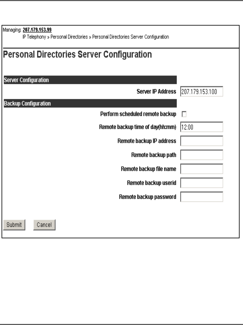
Page 262 of 910 Personal Directory, Callers List, and Redial List
553-3001-365 Standard 4.00 August 2005
Figure 44
Personal Directories Server Configuration window

Personal Directory, Callers List, and Redial List Page 263 of 910
IP Line Description, Installation and Maintenance
Table 52 provides a sample IP Phone Application Server configuration.
The Personal Directory, Callers List, and Redial List features are not
available to the user if the Voice Gateway Media Cards to which the IP
Phones are registered lose contact with the Signaling Server. The features
become available again when contact with the Signaling Server is
re-established.
Table 52
Sample IP Phone Application Server configuration
Data field name Example Description
Server Configuration
Server IP Address 92.168.10.12 IP address of the database
server (for example, the
Leader Signaling Server’s
ELAN network interface IP
address)
Backup Configuration
Perform scheduled remote
backup
Checkbox is selected Select checkbox to enable
scheduled remote backups.
Remote backup time of day
(hh:mm)
00:00 the time of day to perform the
backup (default is 00:00
midnight)
Remote backup IP address 47.11.22.11 remote backup server’s IP
address
Remote backup path /auto/etherset remote path where the back
up file will be saved
Remote backup file name ipldb.db file name of the backup file
Remote backup userid etherset login name for the remote
backup
Remote backup password etherset password for remote backup

Page 264 of 910 Personal Directory, Callers List, and Redial List
553-3001-365 Standard 4.00 August 2005
Note: In a node composed of Voice Gateway Media Cards and
Signaling Server(s), IP Phones only register to the Voice Gateway Media
Cards when the Signaling Server(s) are not present due to a failure
condition. Five minutes after a node election is completed, each Voice
Gateway Media Card with IP Phones registered to it checks to see if a
Signaling Server is present in the node. If a Signaling Server is present,
any idle IP Phones that are found are reset (server-switched) back to S1
(Server 1) so they can reregister to the Signaling Server. If an IP Phone
is busy, a one-minute timer is started. Every one minute, the process
comes back to check for idle IP Phones and idle phones are reset. This
checking continues until no IP Phones remain registered to the Voice
Gateway Media Cards.
Configure IP Phone Application Server on a separate
Signaling Server
If the IP Phone Application Server must support more than 1000 users, follow
the steps in Procedure 6 on page 264 to configure the IP Phone Application
Server on a separate Signaling Server.
Procedure 6
Configuring the IP Phone Application Server on a separate Signaling
Server
1In the Element Manager navigator, click IP Telephony > Nodes:
Servers, Media Cards > Configuration to configure a new node.
The Node Configuration window opens. See Figure 45 on page 265.
2Enter a unique Node ID in the New Node field. Click the to Add button.
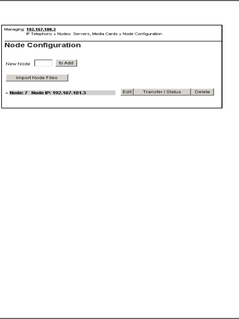
Personal Directory, Callers List, and Redial List Page 265 of 910
IP Line Description, Installation and Maintenance
Figure 45
Add a new node
The Edit window opens.
3Configure the IP addresses and subnet masks for the Signaling Server.
4Click Save and Transfer.
5Configure the IP Phone Application Server using the ELAN network
interface IP address of the new Signaling Server.
In the navigator, click IP Telephony > Personal Directories > Server.
6Configure the backup parameters for Personal Directory, Callers List, and
Redial List and click Submit.
See Figure 46 on page 266.
Refer to Table 52 on page 263 for more information.
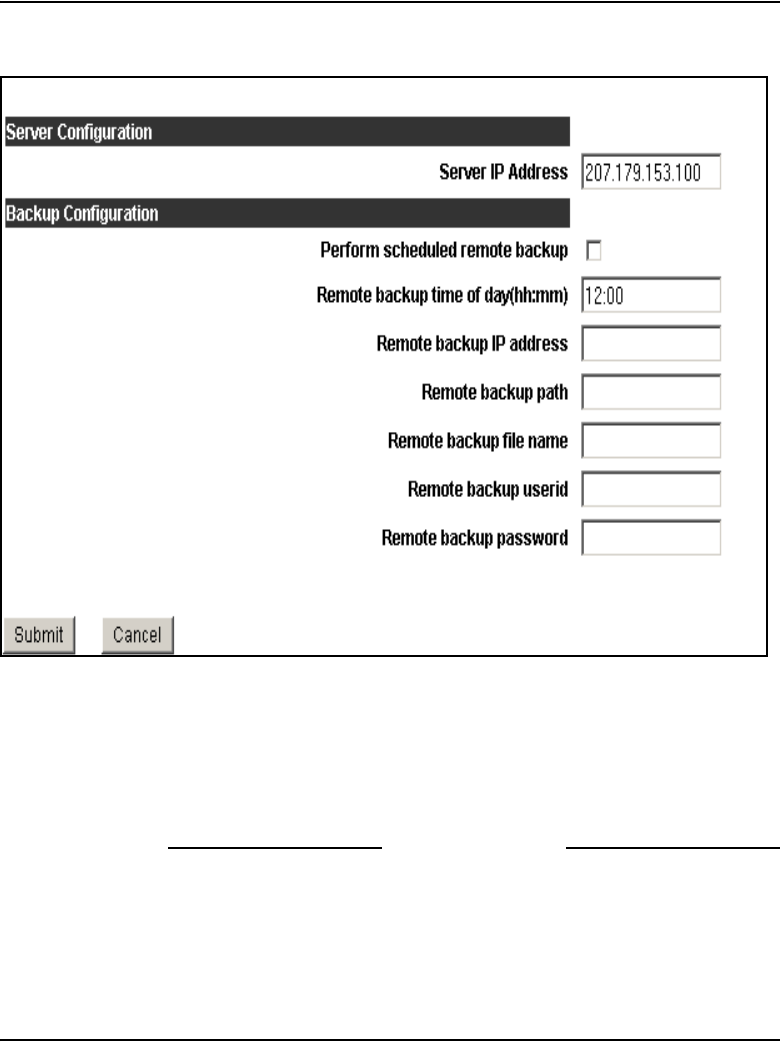
Page 266 of 910 Personal Directory, Callers List, and Redial List
553-3001-365 Standard 4.00 August 2005
Figure 46
Personal Directories Server Configuration window
7Reboot the Signaling Server that was configured as the IP Phone
Application Server.
8When the Signaling Server comes back online, reset all the IP Phones by
performing isetResetAll on every LTPS in the system. See Table 90 on
page 720 for more information.
End of Procedure
Alarms
If the IP Phone Application Server is not installed on the primary Signaling
Server, and the other Signaling Server(s) cannot contact the IP Phone

Personal Directory, Callers List, and Redial List Page 267 of 910
IP Line Description, Installation and Maintenance
Application Server, then an SNMP alarm is raised. The alarm indicates that
the Personal Directory, Callers List, and Redial List are not available. If this
occurs, the other Signaling Server(s) track the Signaling Server where the IP
Phone Application Server resides. When contact with the IP Phone
Application Server is made, Personal Directory, Callers List, and Redial List
access is resumed.
IP Phone Application Server database maintenance
All IP Phone Application Server database maintenance is performed in
Element Manager.
Backup can be configured to occur daily at a scheduled time.
Database recovery can be performed for the entire database of the IP Phone
Application Server or for one user’s entries.
IP Phone Application Server database backup
Follow the steps in Procedure 7 to perform a manual backup of the IP Phone
Application Server’s database.
Note: A scheduled backup of the database can also be configured. Refer
to “Configure the IP Phone Application Server and remote backup” on
page 261.
Procedure 7
Backing up the IP Phone Application Server database server manually
1In the Element Manager navigator, Click IP Telephony > Personal
Directories > Backup and Restore.
The Personal Directories Backup and Restore window opens.
See Figure 47 on page 268.

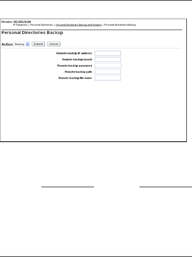
Personal Directory, Callers List, and Redial List Page 269 of 910
IP Line Description, Installation and Maintenance
Figure 48
Personal Directories Backup window
3Enter the data for the Remote backup IP address, Remote backup
userid, Remote backup password, Remote backup path, and Remote
backup file name fields.
4Click Submit.
End of Procedure
Full database recovery
Follow the steps in Procedure 8 on page 270 to perform a full database
backup for the IP Phone Application Server.

Page 270 of 910 Personal Directory, Callers List, and Redial List
553-3001-365 Standard 4.00 August 2005
Procedure 8
Performing a full database recovery
1Click IP Telephony > Personal Directories > Backup and Restore.
The Personal Directories Backup and Restore window opens. See
Figure 49.
Figure 49
Personal Directories Backup and Restore window
2Click Personal Directories Restore.
The Personal Directories Restore window opens. See Figure 50 on
page 271.
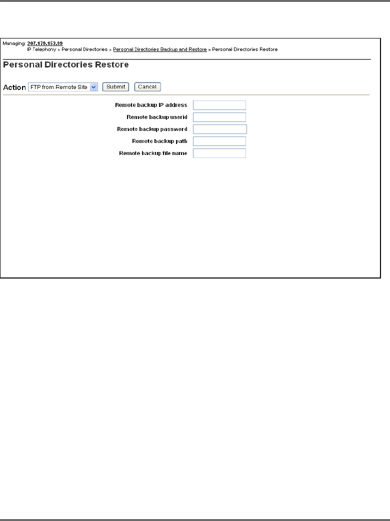
Personal Directory, Callers List, and Redial List Page 271 of 910
IP Line Description, Installation and Maintenance
Figure 50
Personal Directories Restore window
3From the Action drop-down list, select FTP from Remote Site if the
backup is saved on a remote server. If the backup is saved locally, go to
Step 7.
4Enter the data for the Remote backup IP address, Remote backup
userid, Remote backup password, Remote backup path, and Remote
backup file name fields.
5Click Submit.
After the file is transferred by FTP to the local drive, a Switch-over button
appears.
6Click the Switch-over button.

Page 272 of 910 Personal Directory, Callers List, and Redial List
553-3001-365 Standard 4.00 August 2005
7If the backup is saved locally, select Restore All Users from the Action
drop-down list and click Submit.
End of Procedure
Note: When switch-over occurs, the database is off-line for
approximately two minutes.
Selective database recovery for a single user
Follow the steps in Procedure 9 to perform a database recovery for a single
user. The procedure cannot be performed unless there is a valid backup file.
Procedure 9
Performing a selective database recovery
1Click IP Telephony > Personal Directories > Backup and Restore.
The Personal Directories Backup and Restore window opens. See
Figure 51 on page 273.

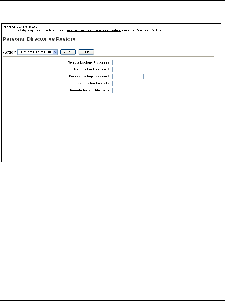
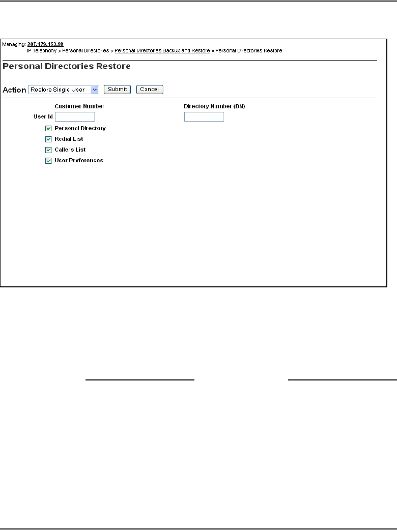
Personal Directory, Callers List, and Redial List Page 275 of 910
IP Line Description, Installation and Maintenance
Figure 53
Personal Directories Restore for a single user window
4Enter the Customer Number and Directory Number (DN) of the user.
5Select the check box(es) of the data that is to be restored.
6Click Submit.
End of Procedure

Page 276 of 910 Personal Directory, Callers List, and Redial List
553-3001-365 Standard 4.00 August 2005
Fault clearance
The recovery of the database clears any faults.
Call Server configuration
To provide password protection for an IP Phone user’s Personal Directory,
Callers List, and Redial List, Station Control Password (SCPW) must be
configured on the Call Server. If SCPW is not configured, password
administration on the IP Phone cannot be accessed.
In LD 15 and in Element Manager, a new prompt, DFLT_SCPW, has been
added to the Flexible Feature Code (FFC) parameters for the Call Server.
When DFLT_SCPW is set to YES, the system assigns a default password (the
primary DN) to IP Phone users when an IP Phone is added or changed in
LD 11.
The new prompt DFLT_SCPW and the existing prompt Station Control
Password Length (SCPL) are prompted only if FFC package 139 is enabled.
The SCPL is also defined in LD 15’s Flexible Feature Code (FFC)
configuration parameters and in Element Manager. If the SCPL length is
changed, the change takes effect only after a data dump and then a sysload of
the Call Server. The SCPL is changed to the new length during the sysload.
If the length has been increased, then “0” is inserted at the beginning of the
Recommendation
Nortel recommends that the IP Phone Application Server be installed on
a dedicated Signaling Server to ensure that database operations do not
affect call processing.
IMPORTANT!
System administrators must ensure that users change the default
password on the IP Phone to control access, as the default password is
the same on all IP Phones when DFLT_SCPW is set to YES.

Personal Directory, Callers List, and Redial List Page 277 of 910
IP Line Description, Installation and Maintenance
SCPW to conform to the new length. If the password length has been reduced,
then the leading digits are removed during the sysload.
Password administration
The Station Control Password (SCPW) controls access to the user’s private
Personal Directory, Callers List, and Redial List information.
When the IP Phone first registers to the system after it has been created, by
default the password protection is turned off. If a default password has been
defined for the user, then the user can enable or disable password protection
and change the password. The changed password is updated on the Call
Server and can be viewed in LD 20. Other applications that use this password,
such as Virtual Office and Remote Call Forward, are affected by the password
change.
Initial password
When an IP Phone first registers with the system, by default the password
protection is turned off. SCPW must be initially configured for each user. If
no SCPW has been defined, password protection for the IP Phone cannot be
enabled. The prompt DFLT_SCPW in LD 15 specifies that a default SCPW
is assigned to an IP Phone user when an IP Phone is added or changed in
LD 11. See Table 53.
Table 53
LD 15 – Enable a default SCPW. (Part 1 of 2)
Prompt Response Description
REQ: CHG Change existing data.
TYPE: FFC Change Flexible Feature Code parameters.
CUST
0 – 99
0 – 31
Customer number
Range for Large System and CS 1000E system
Range for CS 1000M Small System, Meridian 1 Small
System, CS 1000S system, Media Gateway 1000B, and
Media Gateway 1000T

Page 278 of 910 Personal Directory, Callers List, and Redial List
553-3001-365 Standard 4.00 August 2005
Password guessing protection
A password retry counter tracks how many incorrect password entries are
made. If the IP Phone password verification fails three times in one hour, then
the user is locked out for one hour. This means that the Personal Directory,
Callers List, and Redial List cannot be accessed and no password
administration can be performed. A message displays on the IP Phone to
indicate that access is locked.
After one hour, the retry counter is reset and access is unlocked. The retry
counter also resets when the password is entered correctly.
The administrator can reset the counter and unlock the access either in
Element Manager or in LD 32.
...
FFCS (NO) YES Change Flexible Feature Code end-of dialing indicator.
ADLD (0) – 20 Auto Dial Delay (in seconds)
DFLT_SCPW (NO) YES Default Station Control Password
NO = disable Default Station Control Password (default)
When DFLT_SCPW = YES, the system automatically
assigns an SCPW when a new IP Phone 2002, IP Phone
2004, or IP Softphone 2050 is created.
Note: An SCPW is not automatically assigned to an
existing IP Phone unless that IP Phone is given a service
change.
Table 53
LD 15 – Enable a default SCPW. (Part 2 of 2)
Prompt Response Description

Personal Directory, Callers List, and Redial List Page 279 of 910
IP Line Description, Installation and Maintenance
Note: If a user is locked out from using their SCPW to access their
Personal Directory, Callers List, and Redial List, then the user is also
blocked from accessing their Virtual Office login, since VO uses the
same SCPW. Conversely, a user who is locked out from the VO login is
also locked out from accessing their Personal Directory, Callers List, and
Redial List.
Forgotten password
If the user forgets his or her IP Phone password, the administrator can reset
the retry counter and change the user’s password in Element Manager. Once
the administrator changes the password, the lock is released automatically.
User profile management
The User Profile screen(s) in Element Manager are used to perform all
administer-related maintenance functions for a user. These functions include:
• erasing databases for a user
• viewing a user profile
• resetting the password
Once a user profile is selected, a user identification number (ESN+DN) must
be entered to retrieve a user profile from the datbase.When a user profile has
been retrieved from the database, an administrator can perform the following
functions:
• move/copy the following to another user:
— user profile
— Personal Directory
—Callers List
—Redial List
• delete Personal Directory
• delete Callers List
• delete Redial List

Page 280 of 910 Personal Directory, Callers List, and Redial List
553-3001-365 Standard 4.00 August 2005
• delete user preferences
• delete all user-related databases
• reset user’s SCPW to the default
• unlock the user’s SCPW
Note: If a user’s Personal Directory, Callers List, Redial List, and User
Preferences are all removed individually, this has the same effect as
selecting the “Delete all user-related databases” option. Either way, all
the data related to that user is deleted from the database. The user’s entry
must be recreated the next time the user tries to access his or her Personal
Directory, Callers List, and Redial List.
User profile management in Element Manager
To access the user profile management functionality in Element Manager,
follow the steps in Procedure 10.
Procedure 10
Accessing User Profile Management in Element Manager
1Select IP Telephony > Personal Directories > User Profile in the
Element Manager navigator.
The Personal Directories User Profile Configuration window opens.
See Figure 54 on page 281.
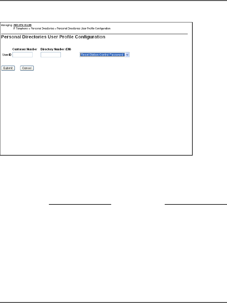
Personal Directory, Callers List, and Redial List Page 281 of 910
IP Line Description, Installation and Maintenance
Figure 54
Personal Directories User Profile Configuration window
2Enter the Customer Number and Directory Number (DN).
3From the drop-down list, select the desired action.
4Click Submit.
End of Procedure
Reset the IP Phone user password
To reset the password for an IP Phone user, follow the steps in Procedure 11
on page 282.
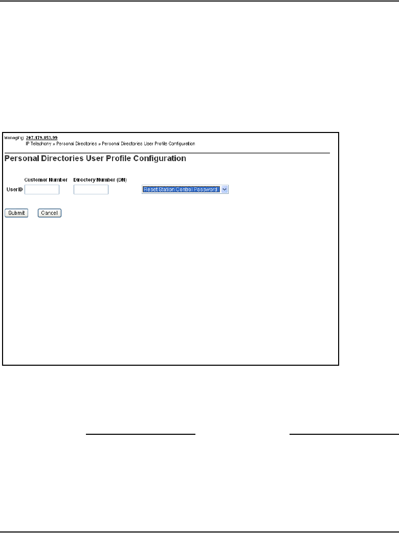
Page 282 of 910 Personal Directory, Callers List, and Redial List
553-3001-365 Standard 4.00 August 2005
Procedure 11
Resetting the IP Phone user password
1Select Reset Station Control Password from the drop-down list from the
drop-down list in the Personal Directories User Profile Configuration
window.
See Figure 55.
Figure 55
Personal Directories User Profile Configuration window
2Enter the User ID.
3Click Submit or click Cancel to cancel the action.
End of Procedure
Copy a Personal Directory to another user
To copy a user’s Personal Directory to another user, follow the steps in
Procedure 12 on page 283.
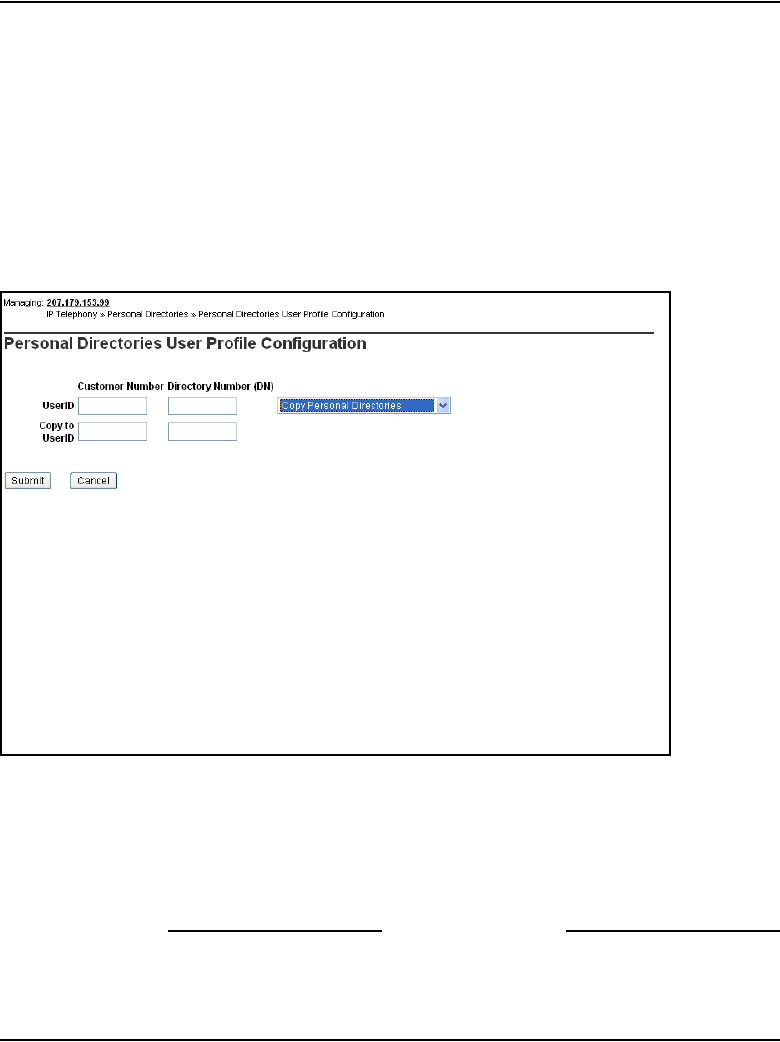
Personal Directory, Callers List, and Redial List Page 283 of 910
IP Line Description, Installation and Maintenance
Procedure 12
Copying a Personal Directory to another user
1Select Copy Personal Directories from the drop-down list from the
drop-down list in the Personal Directories User Profile Configuration
window.
See Figure 55 on page 282.
The Copy Personal Directories fields are displayed. See Figure 56.
Figure 56
Copy Personal Directories
2Enter the User ID of the user from which the Personal Directory is being
copied and the User ID of the user who will receive the Personal Directory
copy.
3Click Submit, or click Cancel to cancel the action.
End of Procedure
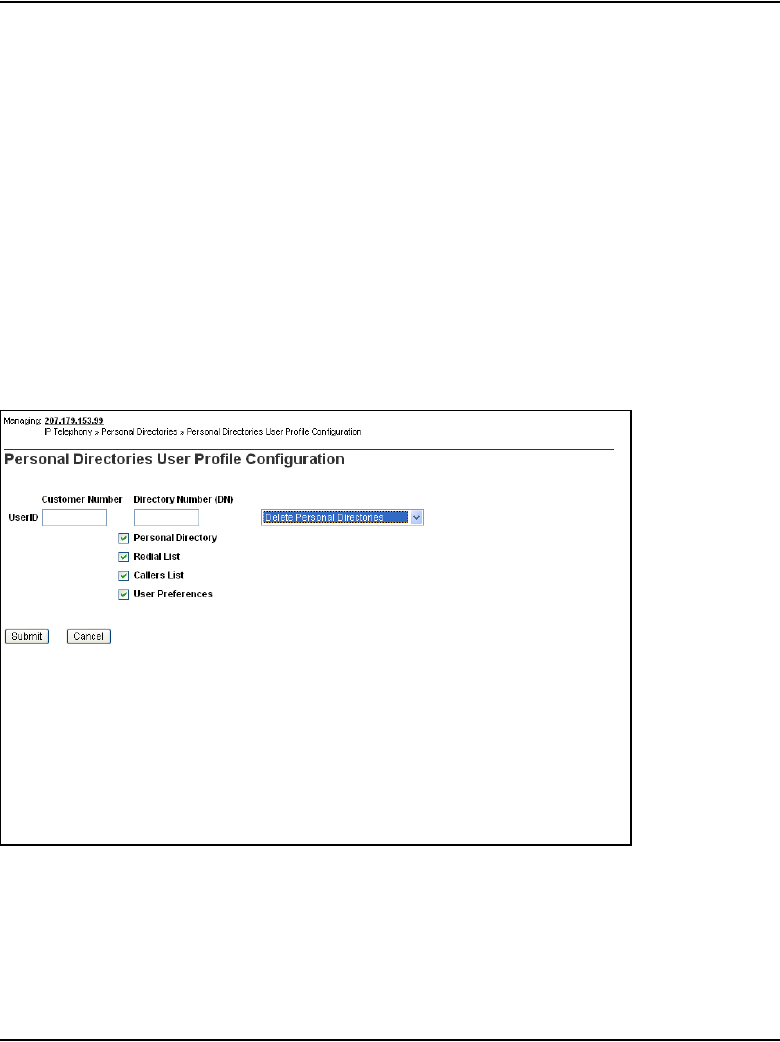
Page 284 of 910 Personal Directory, Callers List, and Redial List
553-3001-365 Standard 4.00 August 2005
Delete a Personal Directory, Callers List, Redial List, or user
preferences
To delete a Personal Directory, Redial List, Callers List, or User Preferences,
follow the steps in Procedure 13.
Procedure 13
Deleting a Personal Directory, Callers List, Redial List, or user
preferences
1Select Delete Personal Directories from the drop-down list from the
drop-down list in the Personal Directories User Profile Configuration
window.
The Delete Personal Directories fields are displayed. See Figure 57.
Figure 57
Delete Personal Directories
2Select the item or items to be deleted.

Personal Directory, Callers List, and Redial List Page 285 of 910
IP Line Description, Installation and Maintenance
3Click Submit, or click Cancel to cancel the action.
End of Procedure
When a new user is configured on the Call Server, a user profile can be copied
to create the new user profile. If a new IP Phone registers and the user is not
found in the database, then the system automatically creates a user profile
based on default settings and the data on the IP Phone. In this case, the
Personal Directory, Callers List, and Redial List are automatically created as
empty lists.

Page 286 of 910 Personal Directory, Callers List, and Redial List
553-3001-365 Standard 4.00 August 2005

Page 287 of 910
IP Line Description, Installation and Maintenance
302
Codecs
Contents
This section contains information on the following topics:
Introduction . . . . . . . . . . . . . . . . . . . . . . . . . . . . . . . . . . . . . . . . . . . . . . 287
Pre-defined codec table . . . . . . . . . . . . . . . . . . . . . . . . . . . . . . . . . . 288
Codec selection. . . . . . . . . . . . . . . . . . . . . . . . . . . . . . . . . . . . . . . . . 288
Codec configuration . . . . . . . . . . . . . . . . . . . . . . . . . . . . . . . . . . . . . . . 290
Codec selection in OTM 2.2. . . . . . . . . . . . . . . . . . . . . . . . . . . . . . . 290
Codec selection in Element Manager. . . . . . . . . . . . . . . . . . . . . . . . 291
Codec registration . . . . . . . . . . . . . . . . . . . . . . . . . . . . . . . . . . . . . . . . . 292
Codec registration for IP Phones . . . . . . . . . . . . . . . . . . . . . . . . . . . 292
Codec registration for DSPs . . . . . . . . . . . . . . . . . . . . . . . . . . . . . . . 293
Voice Gateway codec registration . . . . . . . . . . . . . . . . . . . . . . . . . . 295
Codec negotiation . . . . . . . . . . . . . . . . . . . . . . . . . . . . . . . . . . . . . . . . . 296
Codec sorting . . . . . . . . . . . . . . . . . . . . . . . . . . . . . . . . . . . . . . . . . . 297
Codec selection . . . . . . . . . . . . . . . . . . . . . . . . . . . . . . . . . . . . . . . . . . . 299
H.323’s Master/Slave algorithm. . . . . . . . . . . . . . . . . . . . . . . . . . . . 300
Best Bandwidth Codec Selection algorithm. . . . . . . . . . . . . . . . . . . 301
Introduction
The IP Phones and Voice Gateway Media Cards support different codecs and
codec parameters with different compression rates and audio quality. The CS
1000 and Meridian 1 systems select the appropriate codecs based on
user-configurable parameters.

Page 288 of 910 Codecs
553-3001-365 Standard 4.00 August 2005
For instance, an IP Phone-to-IP Phone call in the same zone within a LAN can
be set up using G.711 at 64 Kbps. For an IP Phone-to-IP Phone call over a
WAN, the call can be set up using G.729A or G.729AB at 8 Kbps. These data
rates and the Voice Gateway Channel Server on the Voice Gateway Media
Card are for the voice stream only. Packet overhead is not included.
Pre-defined codec table
The Line Terminal Proxy Server (LTPS) and the Voice Gateway Channel
Server on the Voice Gateway Media Card have a pre-defined table of codec
option sets that can be supported.
The first entry in the table has the highest quality audio (BQ = Best Quality)
and requires the largest amount of bandwidth. The last entry requires the least
amount of bandwidth (BB = Best Bandwidth) with lower voice quality.
When the Call Server sets up a Call Server connection between an IP
Phone-to-IP Phone or IP Phone-to-Voice Gateway Channel Server, the
pre-defined table determines which codec it selects for that connection. This
information is provided to the system as part of the IP Phone registration
sequence.
For more information about the registration sequence, refer to “Configuring
the DHCP Server” in Converging the Data Network with VoIP
(553-3001-160).
Codec selection
The systems use this information to set up a speech path and select a codec
that both endpoints support. As part of zone management, the system further
selects the codec based on whether it is trying to optimize quality (BQ) or
bandwidth usage (BB).
CAUTION
When voice compression codecs are used, voice quality
is impaired if end-to-end calls include multiple
compressions.

Codecs Page 289 of 910
IP Line Description, Installation and Maintenance
The term “codec” refers to the voice coding and compression algorithm used
by the DSPs on the Voice Gateway Media Card. Different codecs provide
different levels of voice quality and compression properties. The specific
codecs, and the order in which they are used, are configured in the LTPS, and
on the system.
Table 54 shows which codecs are supported on the CS 1000 and Meridian 1
systems.
Note: The MVC 2050 supports only the G.711 codec with 30 ms
payload.
Note: If there are multiple nodes on a system and the same codec is
selected on more than one node, ensure that each node has the same voice
payload size configured for the codec.
Table 54
Supported codecs
Codec Payload size
G.711 a-law, G.711 mu-law, NOVAD 10, 20, and 30 ms
G.729A 10, 20, 30, 40, and 50 ms
G.729AB 10, 20, 30, 40, and 50 ms
G.723.1 130 ms
T. 38 2supported for fax calls on gateway channels
G.711 Clear Channel 2supported for fax calls on gateway channels
Note 1: The G.723.1 codec has bit rates of 5.3 Kbps and 6.3 Kbps. In IP Line 4.5, the G.723.1
codec can only be configured with a 5.3 Kbps bit rate; however, the system accepts both
G.723.1 5.3 Kbps and 6.3 Kbps from the far end.
Note 2: T.38 is the preferred codec type for fax calls over virtual trunks. However, the G.711
Clear Channel codec is used if the far end does not support the T.38 codec.
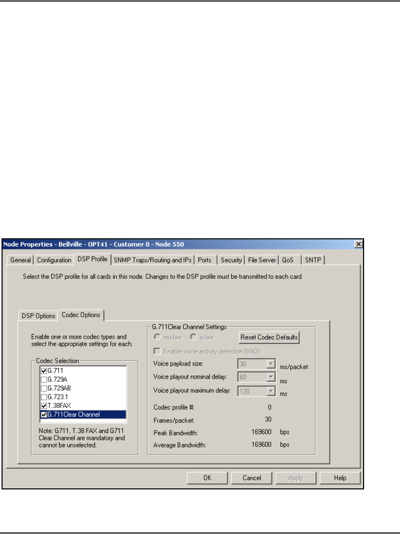
Page 290 of 910 Codecs
553-3001-365 Standard 4.00 August 2005
Codec configuration
Configure the codec in the DSP Profile sections of OTM 2.2 and Element
Manager.
Codec selection in OTM 2.2
Figure 58 shows the list of codecs available on the DSP Profile tab within
OTM’s IP Line 4.5 application. The Codec Options sub-tab presents a table
of different sets of codec options identified by a codec setting index number.
There is a list of up to 32 codec settings for G.711, G.729A, and G.729AB.
The lesser codec setting index corresponds to BQ (Best Quality) in LD 117
zone configuration. The greater codec setting index corresponds to BB (Best
Bandwidth). For more information, see Converging the Data Network with
VoIP (553-3001-160).
Figure 58
Codec list on OTM 2.2
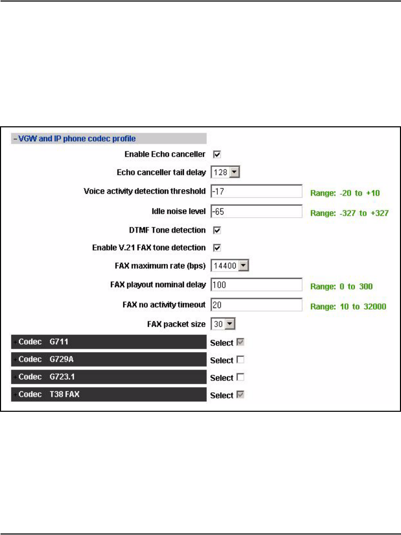
Codecs Page 291 of 910
IP Line Description, Installation and Maintenance
For more information, see “Configure DSP profile data” on page 472.
Codec selection in Element Manager
Figure 59 shows the list of codec types that are displayed in Element
Manager.
Figure 59
Codec list in Element Manager
The G.711 and T.38 Fax codecs are automatically selected and cannot be
un-selected. Even though these codecs cannot be un-selected, the payload
size and the jitter buffer for G.711 can be changed. For G.711 Clear Channel,
only the jitter buffer can be changed.

Page 292 of 910 Codecs
553-3001-365 Standard 4.00 August 2005
Select any two, any one, or none of the G.729A, and G.723.1 codecs. If the
G.729A codec is selected, the payload size and the jitter buffer settings can
be changed. If the G.723.1 codec is selected, only the jitter buffer can be
changed, as the only supported payload size is 30 msec.
For codec configuration in Element Manager, see “Configure Voice Gateway
Profile data” on page 379.
Codec registration
After the configuration of codecs is complete, the IP Phones and DSPs have
to register the configured codecs with the Call Server.
Codec registration for IP Phones
The IP Phones always register both the G.711 a-law and mu-law codecs, as
well as all codec(s) configured by the user. The codecs that can be configured
by the user are G.729A, G.729AB, and G.723.1.
The minimum number of codecs registered for an IP Phone is two: G.711
a-law and G.711 mu-law (G.711 is always configured).
The maximum number of codecs registered for an IP Phone is five: G.711
a-law, G.711 mu-law, G729A, G729AB, and G.723.1.
Note: IP Phones do not register the fax codecs (T.38 and G.711 Clear
Channel).
Example 1
A user configures a G.711 mu-law codec (with a 30 msec payload) and a
G.723.1 codec (with a 30 msec payload).
The following three codecs are actually registered:
1G.711 mu-law (30 msec)
2G.711 a-law (30 msec)
3G.723.1 (30 msec)

Codecs Page 293 of 910
IP Line Description, Installation and Maintenance
Example 2
A user configures four codecs:
1G.711 a-law codec with a 10 msec payload
2G.729A codec with 50 msec payload
3G.729AB codec with 30 msec payload
4G.723.1 codec with a 30 msec payload
The following five codecs are actually registered:
1G.711 a-law (10 msec)
2G.711 mu-law (10 msec)
3G.729A (50 msec)
4G.729AB (30 msec)
5G.723.1 (30 msec)
Codec registration for DSPs
DSPs register the following codecs:
• both G.711 a-law and G.711 mu-law codecs are always registered
• both fax codecs (T.38 and G.711 Clear Channel) are always registered
• one best bandwidth (BB) codec, if at least one of G.729A, G.729AB, or
G.723.1 codecs was configured. The BB codec is based on the codec
type. The order of preference for choosing the BB codec is G.729AB,
G.729A, and then G.723.1.
IMPORTANT!
When G.723.1 codec is configured on the Media Card 32-port line card,
the number of channels is reduced to 24. This is a limitation of the DSP
software. The unused channels are not registered, therefore the Call
Server software does not access them

Page 294 of 910 Codecs
553-3001-365 Standard 4.00 August 2005
Minimum codecs
The minimum number of codecs registered for DSPs is four:
• G.711 a-law
• G.711 mu-law
•T.38
• G.711 Clear Channel
Maximum codecs
The maximum number of codecs registered for DSPs is six:
• G.711 a-law
• G.711 mu-law
•T.38
• G.711 Clear Channel
• one of G.729AB and/or G.729A, or G.723.1
Example 1
A user configures four codecs:
1G.711 a-law codec with a 10 msec payload
2G.729A codec with 50 msec payload
3G.729AB codec with 30 msec payload
4G.723.1 codec with a 30 msec payload
The following six codecs are actually registered:
1G.711 a-law (10 msec)
2G.711 mu-law (10 msec)
3G.729AB (30 msec)
4G.729A (50 msec)
5T.38
6G.711 Clear Channel

Codecs Page 295 of 910
IP Line Description, Installation and Maintenance
The G.729AB codec is selected, as it is the first in the order of preference of
the BB codecs. The G.723.1 codec does not get registered.
Example 2
A user configures three codecs:
1G.711 mu-law codec with a 20 msec payload
2G.729A codec with 30 msec payload
3G.723.1 codec with a 30 msec payload
The following five codecs are actually registered:
1G.711 mu-law (20 msec)
2G.711 a-law (20 msec)
3G.729A (30 msec)
4T.38
5G.711 Clear Channel
The G.729A codec is selected, as it precedes the G.723.1 codec in the order
of preference of the “best bandwidth” codecs.
Voice Gateway codec registration
The Voice Gateway registers codecs for the gateway channels as follows:
• G.711 a-law and G.711 mu-law are always registered.
• T.38 and G.711 Clear Channel fax codecs are always registered. G.711
Clear Channel is used for IP Trunk connections to BCM, which does not
support T.38 fax.
• A minimum of two codecs are registered if only G.711 was configured.
• A maximum of four codecs can be registered - the G.711 a-law and
mu-law for BQ codec, and some BB codecs (defined by the following
rules).
— If the G.729A codec is configured, only the G.729A codec is
registered with the Call Server.

Page 296 of 910 Codecs
553-3001-365 Standard 4.00 August 2005
— If the G.729AB codec is configured, the G.729A codec and the
G.729AB codec are registered with the Call Server.
— If the G.723 codec is configured, the G.723 codec is registered with
the Call Server.
Example 1
G.711 a-law, G.729A, G.729AB, and G.723.1 are configured.
The Voice Gateway registers G.711 a-law, G.711 mu-law, G.729A, and
G.729AB.
Example 2
G.711 mu-law, G.729A, and G.723.1 are configured.
The Voice Gateway registers G.711 a-law, G.711 mu-law, and G.729A.
Example 3
G.711 mu-law and G.723.1 are configured.
The Voice Gateway registers G.711 a-law, G.711 mu-law, and G.723.1.
Codec negotiation
For every virtual trunk call, a common codec must be selected for the call.
This is known as codec negotiation. Codec negotiation for virtual trunk calls
is performed through the H.323 FastStart and Terminal Capability Set (TCS)
messages.
For a call setup with the FastStart procedure, the originating node sends its
codec list in the FastStart element in the SETUP message to the terminating
node. For a call setup using the SlowStart procedure or for a call modification
(media redirection), each node sends its codec list in the TCS message to the
other node.

Codecs Page 297 of 910
IP Line Description, Installation and Maintenance
Codec sorting
Before sending a codec list in FastStart and TCS messages, the codec list
must be sorted according to the BB or BQ policy. This is determined by the
following:
• the zone configuration of the IP Phone/DSP involved in the call
• the zone configuration of the virtual trunk used for the call
Codec sorting methods
There are two methods for sorting the codec list:
1BQ sorting – the codec list is sorted so that the first codec in the list is the
best BQ codec, the second codec is the second best BQ codec in the list,
and so on.
2BB sorting – the codec list is sorted so that the first codec in the list is the
best BB codec, the second codec is the second best BB codec in the list,
and so on.

Page 298 of 910 Codecs
553-3001-365 Standard 4.00 August 2005
Table 55 shows the codec list sorting order for the BQ and BB codecs. To
know if a codec is BQ (as compared to another codec), refer to the lists in
columns 1 and 2. To determine if a codec is BB (as compared to another
codec), refer to the lists in columns 3 and 4. The BQ or BB codec is listed at
the top of the column.
Table 55
BQ and BB codec sorting lists
Best Quality (BQ) sorting Best Bandwidth (BB) sorting
For mu-law systems For a-law systems For mu-law systems For a-law systems
G.71_mu_law_10msec
G.711_mu_law_20msec
G.711_mu_law_30msec
G.711_a_law_10msec
G.711_a_law_20msec
G.711_a_law_30msec
G.729A_10msec
G.729A_20msec
G.729A_30msec
G.729A_40msec
G.729A_50msec
G.729AB_10msec
G.729AB_20msec
G.729AB_30msec
G.729AB_40msec
G.729AB_50msec
G.723.1_5.3kbps_30ms
G.723.1_6.4kbps_30ms
T. 3 8
G.711CC
G.711_a_law_10msec
G.711_a_law_20msec
G.711_a_law_30msec
G.711_mu_law_10msec
G.711_mu_law_20msec
G.711_mu_law_30msec
G.729A_10msec
G.729A_20msec
G.729A_30msec
G.729A_40msec
G.729A_50msec
G.729AB_10msec
G.729AB_20msec
G.729AB_30msec
G.729AB_40msec
G.729AB_50msec
G.723.1_5.3kbps_30ms
G.723.1_6.4kbps_30ms
T.3 8
G.711CC
G.729AB_50msec
G.729AB_40msec
G.729AB_30msec
G.729AB_20msec
G.729AB_10msec
G.729A_50msec
G.729A_40msec
G.729A_30msec
G.729A_20msec
G.729A_10msec
G.723.1_5.3kbps_30ms
G.723.1_6.4kbps_30ms
G.711_mu_law_30msec
G.711_mu_law_20msec
G.711_mu_law_10msec
G.711_a_law_30msec
G.711_a_law_20msec
G.711_a_law_10msec
T.3 8
G.711CC
G.729AB_50msec
G.729AB_40msec
G.729AB_30msec
G.729AB_20msec
G.729AB_10msec
G.729A_50msec
G.729A_40msec
G.729A_30msec
G.729A_20msec
G.729A_10msec
G.723.1_5.3kbps_30ms
G.723.1_6.4kbps_30ms
G.711_a_law_30msec
G.711_a_law_20msec
G.711_a_law_10msec
G.711_mu_law_30msec
G.711_mu_law_20msec
G.711_mu_law_10msec
T. 3 8
G.711CC

Codecs Page 299 of 910
IP Line Description, Installation and Maintenance
Codec selection
For every virtual trunk call, a codec must be selected before the media path is
opened.
When a call setup with the FastStart procedure is used, the terminating node
selects a common codec and sends the selected codec to the originating node.
For a call modification (media redirection) or for a call setup using the
SlowStart procedure, the codec selection occurs on both nodes. Each node has
two codec lists: its own list and the far-end’s list. To select the same codec on
both nodes, it is essential to use the same codec selection algorithm on both
nodes.
For the codec selection, both the near- and far-end codec lists are retrieved:
• The far-end list is not modified because it is already sorted when it is
received (in FastStart or TCS message).
• The near-end list is sorted and then expanded to include lower payloads,
the same way it is done before sending the codec list in FastStart
message.
The following conditions are met before codec selection occurs:
• There are two codec lists:
— The near-end list is the codec list of the local unit.
— The far-end list is the codec list received from the far end.
• Each codec list can contain more than one payload size for a given codec
type. The codec list depends on the codec configuration.
• Each codec list is sorted by order of preference. The first codec in the
near-end list is the near-end’s most preferred codec and the first codec in
far-end list is the far end’s most preferred codec, and so on.

Page 300 of 910 Codecs
553-3001-365 Standard 4.00 August 2005
Once the above conditions are met, a codec selection algorithm is used to
select the codec to be used for a call. There are two different codec selection
algorithms:
1H.323’s Master/Slave algorithm
2Best Bandwidth codec Selection algorithm
H.323’s Master/Slave algorithm
The codec selection algorithm proposed by the H.323 standard involves a
Master/Slave negotiation, initiated each time two nodes exchange their
capabilities (TCS message). The Master/Slave information decides that one
node is Master and the other node is Slave. The outcome of the Master/Slave
negotiation is not known in advance, it is a random result: one node could be
Master then Slave (or Slave then Master) during the same call.
• The Master node uses its own codec list as the preferred one. From the
far-end list, it finds the common codec.
The Master gets the first codec in its own list (Codec1). The Master then
checks the far-end list to see if Codec1 is a common codec (that is, is
Codec1 also listed in the far-end list). If Codec1 is common to both lists,
Codec1 becomes the selected codec. Otherwise, the Master obtains the
second codec from its own list and repeats the search in the far-end list,
and so on.
• The Slave node uses the far-end list as the preferred list. The Slave
selects a codec from the far-end list and then searches in its own list to
find the common codec.
The issues caused by the Master/Slave algorithm are due to the random nature
of the Master/Slave information. The codec that is selected and used during a
virtual trunk call cannot be pre-determined. This can make bandwidth usage
calculations and bandwidth management difficult.

Codecs Page 301 of 910
IP Line Description, Installation and Maintenance
Known issues include:
• After an on-hold and off-hold scenario (that triggers Master/Slave
negotiation), the codec used for the restored call can be different than the
codec used before the call was placed on hold. The Master/Slave
information could have been changed when the call was on hold.
• Since the terminating end of a call is always the Master, a call from
Telephone1 (Node1) to Telephone2 (Node2) can use a different codec
than a call from Telephone2 (Node2) to Telephone1 (Node1).
• For tandem calls, the Master/Slave information is not relevant. That is,
the Master/Slave information is designed to be used only between two
nodes, not among three or more nodes. The Master/Slave algorithm
makes the codec selection for tandem calls more complex and inefficient.
To solve the issues, another codec selection algorithm was needed. This
algorithm is called the Best Bandwidth codec Selection algorithm and is not
based on the unpredictable Master/Slave information.
The Best Bandwidth codec Selection algorithm is used for virtual trunk calls
between Nortel equipment, since any change to the Master/Slave algorithm
implies a change to the H.323 standard. The H.323’s Master/Slave algorithm
is used when there is a virtual trunk call between Nortel equipment and
third-party equipment.
Best Bandwidth Codec Selection algorithm
The Best Bandwidth Codec Selection algorithm was implemented to solve
the issues caused by the H.323 Master/Slave algorithm. The Best Bandwidth
Codec Selection algorithm selects one common codec based on two codec
lists. With this algorithm, every time the selection is done using the same two
lists, the selected codec is always the same.
The “Best Bandwidth” codec selection is based on the codec type only; it does
not take into account the fact that some codecs, while generally using less
bandwidth, consume more bandwidth than others at certain payload sizes.
• The Best Bandwidth Codec Selection algorithm finds the first codec in
the near-end list that is also in far-end list (codec is the same type and has
the same payload size). Call the selected codec C1.

Page 302 of 910 Codecs
553-3001-365 Standard 4.00 August 2005
• Find the first codec in the far-end list that is also in the near-end list (same
type, same payload size). Call this codec C2.
• The C1 and C2 codec that is selected is considered to be the BB codec
type. To determine which codec type is Best Bandwidth, the following
rules are used:
— a G.729AB codec is considered BB compared to G.729A, G.723.1,
G.711_mu-Law, and G.711_a-Law codecs
— a G.729A codec is considered BB compared to
G.723.1,G.711_muLaw, and G.711_aLaw codecs
— a G.723.1 codec is considered BB compared to a G.711_mu-Law
and G.711_a-Law codec
— a G.711_mu-Law codec is considered BB compared to a
G.711_a-Law codec
Table 56 shows the codec that would be selected between any two codecs. For
example, if the two codecs are the G.729A and G.723.1, the selected codec is
the G.729A.
Table 56
Best Bandwidth codec Selection between any two codecs types
Codec type G.711_a-Law G.711_mu-Law G.729A G.729AB G.723.1
G.711_a-Law G.711_a-Law G.711_muLaw G.729A G.729AB G.723.1
G.711_mu-Law G.711_mu-Law G.711_mu-Law G.729A G.729AB G.723.1
G.729A G.729A G.729A G.729A G.729AB G.729A
G.729AB G.729AB G.729AB G.729AB G.729AB G.729AB
G.723.1 G.723.1 G.723.1 G.729A G.729AB G.723.1

Page 303 of 910
IP Line Description, Installation and Maintenance
308
Installation and configuration summary
Contents
This section contains information on the following topics:
Introduction . . . . . . . . . . . . . . . . . . . . . . . . . . . . . . . . . . . . . . . . . . . . . . 303
Before you begin . . . . . . . . . . . . . . . . . . . . . . . . . . . . . . . . . . . . . . . . . . 303
Installation summary . . . . . . . . . . . . . . . . . . . . . . . . . . . . . . . . . . . . . . . 304
Voice Gateway Media Card installation summary sheet . . . . . . . . . . . 306
Introduction
This chapter provides a summary of the procedures required to install a new
IP Telephony node, add cards to the node, install the cards, transmit data to
the cards, and install the IP Phones. It also includes information on what is
required before beginning the installation procedures.
Read “Codecs” on page 287 before installing an IP Telephony node.
Before you begin
Ensure that the system meets the following minimum requirements:
• CS 1000 or Meridian 1 system running CS 1000 Release 4.5 software

Page 304 of 910 Installation and configuration summary
553-3001-365 Standard 4.00 August 2005
Installation summary
The following summary of steps can be used as a reference guide to install
and configure an IP Telephony node and Voice Gateway Media Cards on a
system. This summary is intended to serve as a pointer to the more detailed
procedures contained in other chapters and to provide a sequential flow to the
steps involved in the overall installation procedure.
Note: Complete all installation and configuration steps before
transmitting data to the Voice Gateway Media Cards.
1Complete the Voice Gateway Media Card installation summary sheet.
See Table 57 on page 307.
2Complete the IP Phone configuration data summary sheet. See Table 58
on page 308.
3Install the hardware components:
a. Install the Voice Gateway Media Card(s). See Procedure 14 on
page 316 for installing the ITG-P 24-port line cards and Procedure 16
on page 324 for installing the Media Card 8-port and 32-port line
cards.
b. Cable the Voice Gateway Media Cards:
i. Install the ELAN subnet, TLAN subnet, serial interface cable for
the ITG-P 24-port line card. See Procedure 18 on page 332.
ii. Install the Shielded 50-pin to Serial/ELAN/TLAN Adapter for the
Media Card 8-port and 32-port line card. See Procedure 19 on
page 336.
4Configure IP Line data on the system:
a. Configure the IP address for the ELAN network interface. See
Procedure 20 on page 337.
b. Configure VoIP bandwidth management zones. See page 338.
c. Configure IP Line physical TNs. See page 342.
d. Configure virtual superloops. See page 347.
e. Configure Small System (if applicable) mapping of virtual superloops.
See page 348.
f. Configure IP Phone features. See page 351.

Installation and configuration summary Page 305 of 910
IP Line Description, Installation and Maintenance
5Configure IP Line data using Element Manager:
a. Manually add an IP Telephony node. See page 370.
b. Configure SNMP traps and community names access for security.
See page 375.
c. Configure DSP Profile data. See page 379.
d. Configure DiffServ CodePoint (DSCP) data, 802.1Q support, and
NAT support. See page 385.
e. Configure Call Server ELAN network interface (Active ELNK)
IP address, TLAN Voice port (RTP UDP port), and the routing tables
on the Voice Gateway Media Card. See page 387.
f. Configure file server access. See page 392.
g. Configure the loss plan. See page 394.
h. Configure Voice Gateway Media Care properties. See page 395.
6Submit and transfer the node information to the Call Server. See
page 398.
7Transmit Voice Gateway Media Card configuration data to the Voice
Gateway Media Cards:
a. Set Leader IP Address. See Procedure 36 on page 402.
b. Transmit node and card properties to the Leader. See Procedure 37
on page 405.
8Upgrade the card software and IP Phone firmware:
a. Verify card software version. See page 420.
b. Verify card firmware release. See page 423.
c. Download software and firmware files from the Nortel web site. See
page 424.
d. Upload the software and firmware files to the file server. See
page 425.
e. Upgrade the software on the Voice Gateway Media Card. See
page 427.
f. Reboot the card. See page 432.
g. Upgrade the firmware on the card. See page 437.

Page 306 of 910 Installation and configuration summary
553-3001-365 Standard 4.00 August 2005
9Configure OTM alarm notification feature to receive IP Line SNMP traps.
See Procedure 68 on page 523.
10 Assemble and install an IP Phone. Refer to IP Phones: Description,
Installation, and Operation (553-3001-368).
11 Change the default IP Line CLI (IPL>) Shell password. See Procedure 69
on page 553.
12 Configure the IP Phone Installer Passwords (see page 543).
a. Enable and set the administrative IP Phone Installer Password. See
Procedure 69 on page 553.
b. If needed, enable and set a temporary IP Phone Installer Password.
See Procedure 70 on page 556.
Voice Gateway Media Card installation summary sheet
Nortel recommends that a Voice Gateway Media Card installation summary
sheet (see Table 57 on page 307) be filled out as the line cards are unpacked,
inventoried, and provisioned. IP address information is usually supplied by
the IP Network Administrator.
To complete the installation summary sheet, the following information is
required:
• MAC address. This is the ELAN network interface MAC address on the
Voice Gateway Media Card faceplate sticker (for example,
00:60:38:01:12:77).
• ELAN network interface IP address, used to perform management
through OTM and to communicate with the system
• TLAN Node IP address for the IP Telephony node
• TLAN network interface IP address on each card
• IP address of the active ELNK Ethernet network interface on the system
core
Nortel recommends that an IP Phone configuration data summary sheet (see
Table 58 on page 308) be filled out as the IP Phones are installed and
configured.

Installation and configuration summary Page 307 of 910
IP Line Description, Installation and Maintenance
Table 57
Voice Gateway Media Card installation summary sheet
Site________________ Meridian 1/CS 1000 system ___________________
Meridian 1/CS 1000 customer________________________
Node ID (Number)________________________
TLAN Node IP address________________________
Meridian 1/CS 1000 active ELNK IP address_______________________
SNMP Manager List IP addresses________________________
TLAN gateway (router) IP address________________________
TLAN subnet mask________________________
ELAN gateway (router) IP address________________________
ELAN subnet mask__________________________
TN
ELAN
Management
MAC address
ELAN
Management IP
address
TLAN (Voice)
Card IP
address
Card role
Leader
Follower
(OTM: Leader1)
Follower
Follower
Follower
Follower
Follower
Follower
Follower
Follower
Follower
Follower

Page 308 of 910 Installation and configuration summary
553-3001-365 Standard 4.00 August 2005
Table 58
IP Phone configuration data summary sheet
No DHCP
Partial DHCP
Full DHCP
IP
address
Subnet
mask
Gateway
IP
address
Connect
Server IP
address*
Node# VTN DN User
Name
User
Location
*Connect Server IP address is the Node IP address of the IP Telephony node.

Page 309 of 910
IP Line Description, Installation and Maintenance
360
Installation and initial configuration of an
IP Telephony node
Contents
This section contains information on the following topics:
Introduction . . . . . . . . . . . . . . . . . . . . . . . . . . . . . . . . . . . . . . . . . . . . . . 310
Equipment considerations . . . . . . . . . . . . . . . . . . . . . . . . . . . . . . . . . . . 311
Required equipment . . . . . . . . . . . . . . . . . . . . . . . . . . . . . . . . . . . . . 311
Optional equipment . . . . . . . . . . . . . . . . . . . . . . . . . . . . . . . . . . . . . 312
Install the hardware components. . . . . . . . . . . . . . . . . . . . . . . . . . . . . . 312
Summary of installation steps . . . . . . . . . . . . . . . . . . . . . . . . . . . . . 313
Identify the IPE card slots on a CS 1000M or Meridian 1 . . . . . . . . 314
Installing and cabling the ITG-P 24-port line card. . . . . . . . . . . . . . 315
Installing and cabling the Media Card 8-port and 32-port line cards 317
Installing the NTCW84JA ITG-specific I/O Panel filter
connector for a Large System. . . . . . . . . . . . . . . . . . . . . . . . . . . . . . 325
Voice Gateway Media Card ELAN and TLAN network interfaces. 329
Initial configuration of IP Line 4.5 data . . . . . . . . . . . . . . . . . . . . . . . . 336
Summary of procedures . . . . . . . . . . . . . . . . . . . . . . . . . . . . . . . . . . 336
Configure IP address for the system active ELNK Ethernet network
interface (LD 117) . . . . . . . . . . . . . . . . . . . . . . . . . . . . . . . . . . . . . . 337
Configure VoIP bandwidth management zones (LD 117) . . . . . . . . 338
Element Manager for Zone Configuration . . . . . . . . . . . . . . . . . . . . 340
Configure physical TNs (LD 14) . . . . . . . . . . . . . . . . . . . . . . . . . . . 342
Using Element Manager for Voice Gateway channels. . . . . . . . . . . 343
Configure virtual superloops for IP Phones . . . . . . . . . . . . . . . . . . . 347

Page 310 of 910 Installation and initial configuration of an IP Telephony node
553-3001-365 Standard 4.00 August 2005
Configure IP Phone features in LD 11. . . . . . . . . . . . . . . . . . . . . . . 351
Configure the IP Phone KEM . . . . . . . . . . . . . . . . . . . . . . . . . . . . . 353
IP Phone dedicated soft keys . . . . . . . . . . . . . . . . . . . . . . . . . . . . . . 358
Node election rules . . . . . . . . . . . . . . . . . . . . . . . . . . . . . . . . . . . . . . . . 359
Introduction
This chapter explains how to install and perform the initial configuration of
new IP Telephony nodes, Voice Gateway Media Cards (ITG-P 24-port and
Media Card line cards), and associated cables.
Before installing an IP Telephony node, refer to Converging the Data
Network with VoIP (553-3001-160) for information on IP network
engineering guidelines.
Meridian 1
If configuring IP Line 4.5 on a Meridian 1, complete the remainder of the
configuration of IP Line data using Optivity Telephony Manager (OTM) 2.2.
CS 1000
If configuring IP Line 4.5 on a CS 1000 system, complete the remainder of
the configuration of IP Line data using Element Manager.
Installation and configuration procedures
The following is a list of procedures in this chapter:
• “Installing the ITG-P 24-port line card” on page 316
• “Installing the CompactFlash card on the Media Card” on page 318
IMPORTANT!
The maximum number of Voice Gateway Media Cards that can be
installed in each node is 30. When more than 30 Voice Gateway Media
Cards are needed on a single CS 1000 system, then multiple nodes
must be used. The maximum number of Signaling Servers and Voice
Gateway Media Cards that can be combined within a node is 35.

Installation and initial configuration of an IP Telephony node Page 311 of 910
IP Line Description, Installation and Maintenance
• “Installing the Media Card” on page 324
• “Replacing the existing I/O Panel Filter Connector” on page 326
• “Installing the NTMF94EA ELAN, TLAN, serial interface cable” on
page 332 for the ITG-P Line Card
• “Installing the Shielded 50-pin to Serial/ELAN/TLAN Adapter onto the
Media Card” on page 336 for the Media Card
• “Configuring the ELAN network interface IP address for the active
ELNK” on page 337
Equipment considerations
This section lists the required and optional equipment that can be used to
install, configure, and maintain the Voice Gateway Media Cards and IP
Phone products.
Required equipment
The required equipment includes the following:
• a PC to manage IP Line 4.5, with the following installed:
— OTM 2.2 must be installed for a Meridian 1 system
— Internet Explorer 6.0.2600 (or later) to run Element Manager for
CS 1000 systems
• local TTY or terminal in a switch room. This is required for Leader
configuration.
• two shielded CAT 5 Ethernet cables to connect the Voice Gateway
Media Card to an external switch (recommended) or hub equipment
• 10/100BaseT network interface (optional auto-sensing) to support
TLAN and 10BaseT ELAN network interface connections
• 10/100BaseT network interface (optional auto-sensing) in each location
where an IP Phone resides
• serial cables

Page 312 of 910 Installation and initial configuration of an IP Telephony node
553-3001-365 Standard 4.00 August 2005
Optional equipment
The optional equipment includes the following:
• a server configured with Dynamic Host Configuration Protocol (DHCP);
for example, a Nortel NetID server
• an external modem router to enable remote dial-up connection to the
ELAN subnet for technical support (Nortel RM356 modem router is
recommended)
Install the hardware components
There are three cards that use the IP Line 4.5 software; the Media Card 8-port
and 32-port line cards and the ITG-P 24-port line card.
• See page 317 for installation instructions for the Media Card 8-port and
32-port line card.
• See page 315 for installation instructions for the ITG-P 24-port line card.
Voice Gateway Media Card
If a Media Card 32-port card, a Media Card 8-port card, or an ITG-P 24-port
card is running IP Line 4.5 software, it is known as a Voice Gateway Media
Card.
IMPORTANT!
The ITG-P 24-port card is not supported in the Media Gateway 1000E of
the CS 1000E system.

Installation and initial configuration of an IP Telephony node Page 313 of 910
IP Line Description, Installation and Maintenance
Summary of installation steps
The following table summarizes the steps for installing each Voice Gateway
Media Card.
Table 59
Installation summary (Part 1 of 2)
Step
ITG-P 24-port
line card Media Card line card
Determine card slot. See “Identify the IPE card
slots on a CS 1000M or
Meridian 1” on page 314
See “Identify the IPE card
slots on a CS 1000M or
Meridian 1” on page 314
Unpack the card. Remove all contents from the
packaging box.
Remove all contents from
the packaging box.
Install the CompactFlash
Card.
Not applicable Procedure 15 on page 318
Install the Voice Gateway
Media Cards.
Procedure 14 on page 316 Procedure 16 on page 324
Install NTCW84JA
ITG-specific I/O Panel Filter
Connector for
Option 51C/61C/81/81C.
Procedure 17 on page 326 Procedure 17 on page 326
Install the NTMF94EA ELAN,
TLAN, RS-232 Serial
Maintenance I/O interface
cable.
Procedure 18 on page 332 Not applicable
Install the A0852632 Shielded
50-pin to Serial/ELAN/TLAN
Adapter.
Not applicable Procedure 19 on page 336

Page 314 of 910 Installation and initial configuration of an IP Telephony node
553-3001-365 Standard 4.00 August 2005
Identify the IPE card slots on a CS 1000M or Meridian 1
Depending on the module that is used, the ITG-P 24-port line card must be
installed in a specific slot. Use Table 60 to identify the IPE card slots selected
for the Voice Gateway Media Card.
Configure card as a Leader or
Follower.
In OTM 2.2:
Procedure 61 on page 497
In Element Manager:
Procedure 36 on page 402
(Leader)
Procedure 38 on page 411
(Follower)
In OTM 2.2:
Procedure 61 on page 497
In Element Manager:
Procedure 36 on page 402
(Leader)
Procedure 38 on page 411
(Follower)
Add the card and configure
the card properties
In OTM 2.2:
Procedure 52 on page 469
In Element Manager:
Procedure 34 on page 395
In OTM 2.2:
Procedure 52 on page 469
In Element Manager:
Procedure 34 on page 395
Transmit/Transfer properties In OTM 2.2:
Procedure 62 on page 499
Procedure 63 on page 501
In Element Manager:
Procedure 37 on page 405
In OTM 2.2:
Procedure 62 on page 499
Procedure 63 on page 501
In Element Manager:
Procedure 37 on page 405
Table 60
Voice Gateway Media Card installation by module type
C 1000M/Meridian 1 modules ITG-P 24-port line card slots
NT8D37BA/EC IPE modules All available IPE card slots
NT8D37AA/DC IPE modules 0, 4, 8, and 12
Table 59
Installation summary (Part 2 of 2)
Step
ITG-P 24-port
line card Media Card line card
Installation and initial configuration of an IP Telephony node Page 315 of 910
IP Line Description, Installation and Maintenance
Note: EMC restriction must be considered when installing the Voice
Gateway Media Cards. For more information, see “Electro-Magnetic
Containment” on page 897.
Installing and cabling the ITG-P 24-port line card
Each ITG-P 24-port line card requires two slots in the CS 1000 or Meridian 1.
Only the left slot of the card connects to the IPE backplane and I/O panel.
A maximum of eight ITG-P 24-port line cards can be installed in an IPE shelf
in a Large System. The ITG-P 24-port line card can occupy any two adjacent
slots in an IPE shelf, with the left slot of the card plugging into slots 0 to 6
and 8 to 15. The left slot of an ITG-P 24-port line card cannot be plugged into
slot 7, because the XPEC card is situated between slots 7 and 8.
To enable a module to hold the maximum number of ITG-P 24-port line
cards, install each card with the left slot of the card inserted into an
even-numbered slot.
To install an ITG-P 24-port line card, follow the steps in Procedure 14 on
page 316.
CAUTION WITH ESD DEVICES
Wear an ElectroStatic Discharge Strap (ESDS) when
handling ITG-P 24-port and Media Card line cards. As an
additional safety measure, handle all cards by the edges,
and when possible, with the loosened packaging material
still around the component.
WARNING
The CAT5 Ethernet cable between the ITG-P 24-port line
card TLAN network interface and the Layer 2 switch must
have a length of 50 meters or less for proper operation of
the TLAN network interface

Page 316 of 910 Installation and initial configuration of an IP Telephony node
553-3001-365 Standard 4.00 August 2005
Procedure 14
Installing the ITG-P 24-port line card
1For each ITG-P 24-port line card in the node, identify the IPE card slot
selected for the ITG-P 24-port line card. Use the information from the
“Voice Gateway Media Card installation summary sheet” on page 306,
and Table 57 on page 307.
Note: Even though the ITG-P 24-port line card is a two-slot card, only the
left slot is counted for the card slot number. For example, for an ITG-P
24-port line card installed in slots 2 and 3, the slot number is 2.
2Remove any existing I/O panel cabling associated with any card
previously installed in the selected card slot.
3Insert the ITG-P 24-port line card into the card guides and gently push it
until it makes contact with the backplane connector. Hook the locking
devices.
Note 1: The red LED on the card faceplate remains lit until the card is
configured and enabled in the software, at which point the LED turns off.
Note 2: The faceplate display window displays start-up self-test results
(T:xx) and status messages. A display “F:XX” indicates a failure of the
self-test. It is normal for the ITG-P 24-port line card to display “F:10”
during the start-up self-test. F:10 indicates that the self-test did not find a
Security Device. The ITG-P 24-port line card does not have a security
device.
Some failures indicate that the card must be replaced. See Table 79 on
page 689 for a list of the ITG-P 24-port line card display codes.
End of Procedure
Table 61
ITG-P 24-port line card installation by module type
Meridian 1 Modules ITG-P 24-port line card
NT8D37BA/EC IPE modules All available IPE card slots
NT8D37AA/DC IPE modules 0, 4, 8, and 12

Installation and initial configuration of an IP Telephony node Page 317 of 910
IP Line Description, Installation and Maintenance
Installing and cabling the Media Card
8-port and 32-port line cards
The Media Card 32-port line card is the successor of the ITG-P 24-port line
card. It increases the packet processing power of the ITG-P 24-port line card,
increases the channel density from 24 to 32 ports, and reduces the slot usage
from a dual slot to a single IPE slot.
Both the Media Card 32-port and 8-port line card require only one slot in the
IPE shelf.
CompactFlash installation
The Media Card package contains the following items:
•Media Card
• CompactFlash card
• retaining pin
The CompactFlash card must be installed on the Media Card before installing
the Media Card in the system. Follow the steps in Procedure 15 on page 318
to install the CompactFlash card.
Note: If it is necessary to remove the CompactFlash card, follow the
steps outlined in Procedure 107 on page 769.
CAUTION WITH ESDS DEVICES
Wear an ElectroStatic Discharge strap when handling
Media Card line cards. As an additional safety measure,
handle all cards by the edges, and when possible, with
the loosened packaging material still around the
component
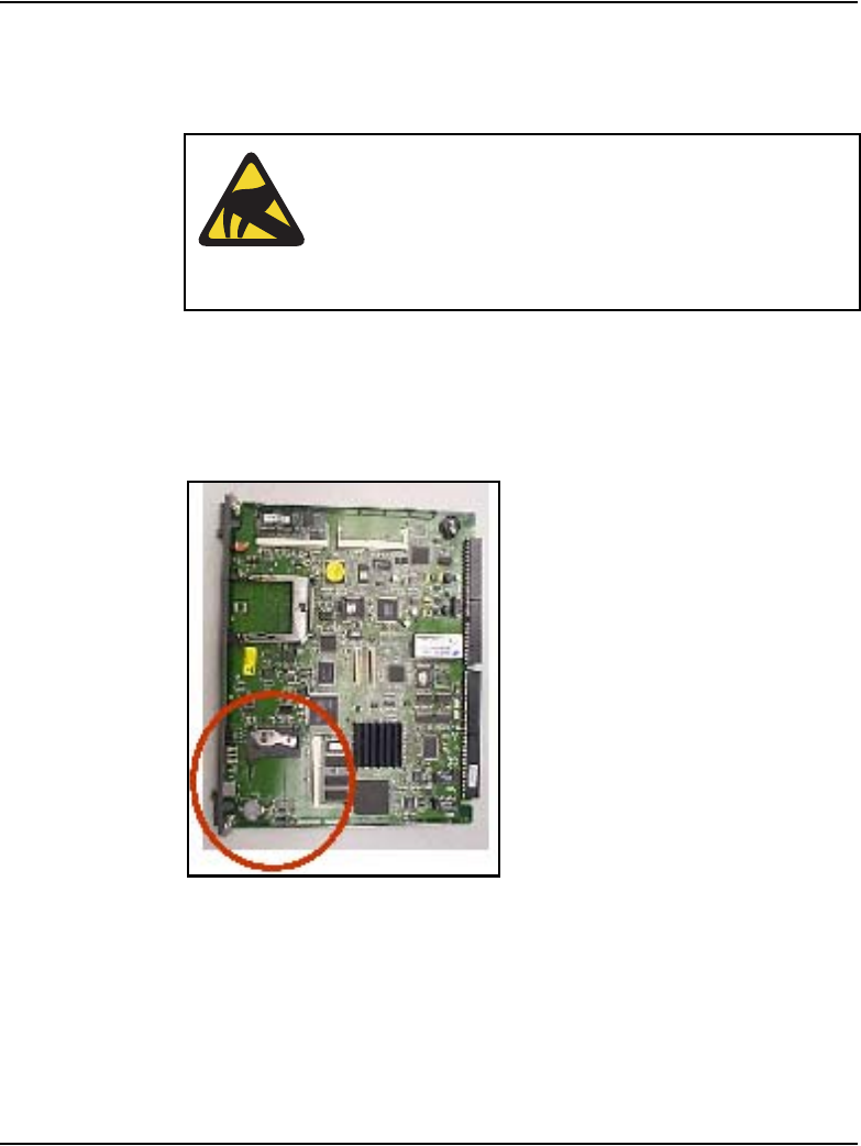
Page 318 of 910 Installation and initial configuration of an IP Telephony node
553-3001-365 Standard 4.00 August 2005
Procedure 15
Installing the CompactFlash card on the Media Card
1Remove the Media Card and CompactFlash card from the packaging.
2Locate the CompactFlash card socket in the lower left-hand corner of the
Media Card. See Figure 60.
Figure 60
CompactFlash card socket on Media Card
3Position the CompactFlash card with the label facing up, the metal clip
pulled up, and contact pins toward the socket as shown in Figure 61 on
page 319.
CAUTION WITH ESDS DEVICES
Observe the necessary precautions for handling
ESD-sensitive devices. Wear a properly connected
anti-static wrist strap while removing the cards from
the packaging and work on a static-dissipating
surface.

Installation and initial configuration of an IP Telephony node Page 319 of 910
IP Line Description, Installation and Maintenance
Figure 61
Position the CompactFlash in socket
4Insert the CompactFlash card in the socket.
Ensure force is applied equally at both ends of the CompactFlash when
pushing it in. See Figure 62 on page 320.

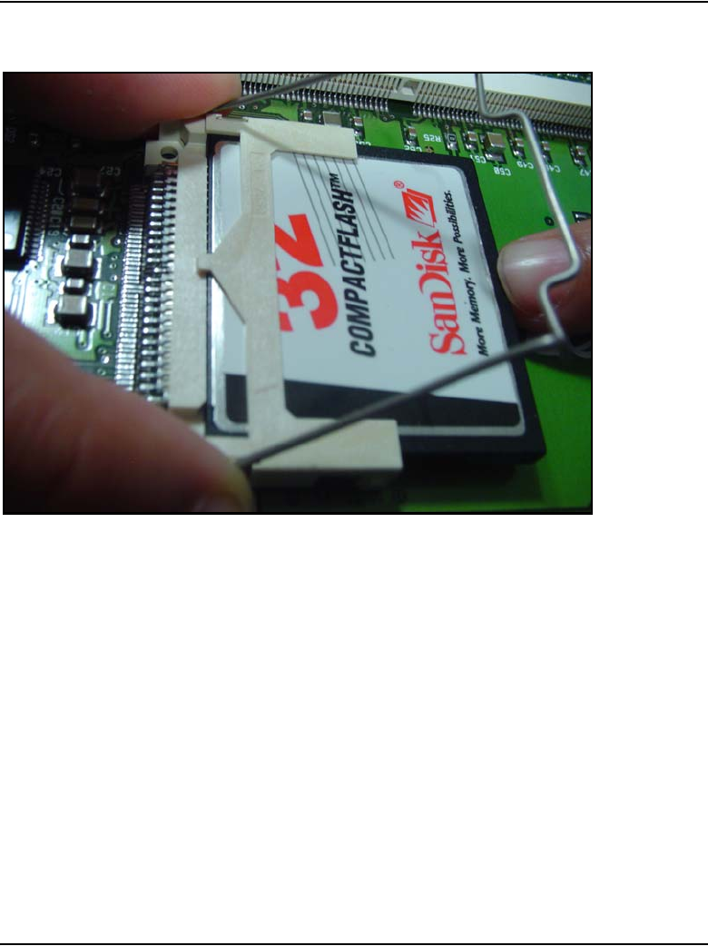

Page 322 of 910 Installation and initial configuration of an IP Telephony node
553-3001-365 Standard 4.00 August 2005
Figure 64
Lock card into place

Installation and initial configuration of an IP Telephony node Page 323 of 910
IP Line Description, Installation and Maintenance
Figure 65
CompactFlash card locked into position
End of Procedure

Page 324 of 910 Installation and initial configuration of an IP Telephony node
553-3001-365 Standard 4.00 August 2005
Install the Media Card
To install a Media Card, follow the steps in Procedure 16.
Procedure 16
Installing the Media Card
1For each Media Card in the node, identify the IPE card slot selected for
the Media Card.
Use the information from the “Voice Gateway Media Card installation
summary sheet” on page 306, and Table 57 on page 307.
2Remove any existing I/O panel cabling associated with any card
previously installed in the selected card slot.
3Insert the Media Card into the card guides and gently push it until it makes
contact with the backplane connector. Hook the locking devices.
Note 1: The red LED on the faceplate remains lit until the card is
configured and enabled in the software, at which point the LED turns off.
Note 2: The card faceplate display window displays start-up self-test
results (T:xx) and status messages. A display “F:xx” indicates a failure of
the self-test. Some failures indicate that the card must be replaced.
Note 3: Refer to “Transfer node configuration from Element Manager to
the Voice Gateway Media Cards” on page 401.
Note 4: Refer to Table 80 on page 691 for a listing of the Media Card
display codes.
End of Procedure
Table 62
Media Card installation by module type
Meridian 1 Modules Media Card
NT8D37BA/EC IPE modules All available IPE card slots
NT8D37AA/DC IPE modules 0, 4, 8, and 12

Installation and initial configuration of an IP Telephony node Page 325 of 910
IP Line Description, Installation and Maintenance
Installing the NTCW84JA ITG-specific I/O Panel filter
connector for a Large System
For Large Systems, the standard IPE module I/O filtering is provided by the
50-Pin filter connectors mounted in the I/O Panel on the back of the IPE shelf.
The filter connector attaches externally to the MDF cables and internally to
the NT8D81AA Backplane to the I/O Panel ribbon cable assembly.
For 100BaseTX TLAN operation, the standard I/O filter connector must be
replaced with the NTCW84JA ITG Line-specific I/O filter connector for the
following:
• the leftmost of the two card slots occupied by the ITG-P 24-port line card
• the slot occupied by the Media Card
For Small Systems, and CS 1000S systems, the standard I/O filter connector
already supports 100BaseTX TLAN operation.
To replace an existing I/O Panel Filter Connector, follow the steps in
Procedure 17 on page 326.
Note: This NTCW84JA ITG-specific Filter Connector is not required
on Small Systems or CS 1000S systems.
CAUTION
For Large systems manufactured between 1998-1999
and shipped in North America, the IPE modules have the
NT8D81BA Backplane to I/O Panel ribbon cable
assembly with a non-removable filter connector. The
NT8D81BA is compatible with a 10BaseT operation of
the TLAN network interface, but if a 100BaseT operation
of the TLAN network interface is required, order the
NT8D81AA Backplane to I/O Panel ribbon cable
assembly to replace it. Do not install the NTCW84JA
ITG-specific filter connector onto the existing
non-removable filter connector.

Page 326 of 910 Installation and initial configuration of an IP Telephony node
553-3001-365 Standard 4.00 August 2005
Replace existing I/O panel filter connector
The standard I/O filter connector is shielded metal with a black plastic insert
connector. The NTCW84JA connector uses yellow warning labels to indicate
EMC filtering modifications and which MDF connection points can support
100BaseT connections.
Procedure 17
Replacing the existing I/O Panel Filter Connector
1Before any of the following steps, remove the ITG pack, or any other IPE
pack, from the IPE shelf card slot corresponding to the I/O Panel
connector to be removed.
Note: Make sure to use the I/O Panel Filter Connector which
corresponds to the left slot number of the DCHIP card.
2Remove the NT8D81AA Backplane to I/O Panel ribbon cable assembly,
that is connected to the Backplane side of the existing block, by releasing
the latching pins on the filter block and pulling the NT8D81AA cable away.
3Unscrew the existing filter connector from the I/O panel. There is one
screw on the lower front of the connector and one screw on the upper
back of the connector. Remove the connector.
4Re-position the new NTCW84JA filter connector in the now vacant I/O
panel opening. See Figure 66 on page 327.
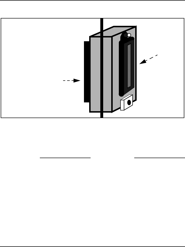
Installation and initial configuration of an IP Telephony node Page 327 of 910
IP Line Description, Installation and Maintenance
Figure 66
NTCW84JA 50 pin ITG-specific I/O Panel filter connector for Large Systems
5Attach the new NTCW84JA ITG-specific filter connector to the I/O panel
by securely fastening the top back screw and the bottom front screw.
6Reconnect the NT8D81AA cable and secure it in place by snapping shut
the locking latches provided on the NTCW84JA connector.
End of Procedure
System
backplane
side
(inside I/O Panel)
NT8D81AA Cable
MDF
Cable
Exterior side of
System I/O Panel
system (to MDF,
and so on)

Page 328 of 910 Installation and initial configuration of an IP Telephony node
553-3001-365 Standard 4.00 August 2005
Incorrect configuration problems
TLAN network interface operation problems can arise from the standard I/O
filter connector in IPE modules on Large Systems. Some problem scenarios
and their respective solutions are outlined in Table 63.
Table 63
I/O filter connector
Scenario Solution
The installer forgets to replace the standard
IPE module I/O filter connector with the
provided Voice Gateway Media
Card/ITG-specific filter connector that
removes filtering from pairs 23 and 24.
Correctly install the Voice Gateway Media
Card/ITG-specific filter connector by replacing
the standard IPE Module I/O filter connector.
The installer installs the Voice Gateway
Media Card/ITG-specific filter connector on
top of the standard IPE module I/O filter
connector.
Correctly install the Voice Gateway Media
Card/ITG-specific filter connector by replacing
the standard IPE Module I/O filter connector.
The installer encounters an IPE module that
is equipped with standard filter connectors
molded onto the backplane I/O ribbon cable
assemblies. The installer does not replace the
IPE module backplane I/O ribbon cable
assemblies with the ones that have
interchangeable I/O filter connectors.
Order new IPE Module Backplane I/O ribbon
cable assemblies that have interchangeable
I/O filter connectors if it becomes necessary to
use one of the IPE Modules with molded-on
I/O filter connectors.
The UTP cabling from the TLAN network
interface to the Layer 2 switch does not meet
the UTP CAT5 termination and impedance
uniformity standards.
Always ensure that UTP cabling from the
TLAN network interface to the Layer 2 switch
is CAT5-compliant.

Installation and initial configuration of an IP Telephony node Page 329 of 910
IP Line Description, Installation and Maintenance
Voice Gateway Media Card ELAN and TLAN network
interfaces
CS 1000M and Meridian 1 systems
The ELAN and TLAN network interfaces are provided by one of the
following:
• NTMF94EA ELAN, TLAN, RS-232 Serial Maintenance I/O interface
cable (see Figure 67 on page 331)
• A0852632 Shielded 50-pin to Serial/ELAN/TLAN Adapter (see
Figure 68 on page 334)
The ITG-P 24-port line card uses the NTMF94EA ELAN, TLAN, RS-232
Serial Maintenance I/O interface cable.
The Media Card uses the A0852632 Shielded 50-pin to Serial/ELAN/TLAN
Adapter.
The ELAN network interface supports 10BaseT operation and the TLAN
network interface supports 10/100BaseT operation. To support the 100BaseT
operation on Large Systems, the TLAN network interface requires
specialized I/O panel mounting connectors. These replace the standard
connectors provided on the system.
Cables and connectors for the ELAN and TLAN network interface functions
include the following:
• the NTCW84JA I/O panel filter block
• NTMF94EA ELAN, TLAN, RS-232 Serial Maintenance I/O interface
cable
• A0852632 Shielded 50-pin to Serial/ELAN/TLAN Adapter. Standard
shielded, CAT5 LAN cables (<100 meters) are recommended to attach
the LAN ports to the local network.

Page 330 of 910 Installation and initial configuration of an IP Telephony node
553-3001-365 Standard 4.00 August 2005
CS 1000S systems
For information on Voice Gateway Media Card ELAN and TLAN network
interfaces on a CS 1000S system, refer to Communication Server 1000S:
Installation and Configuration (553-3031-210).
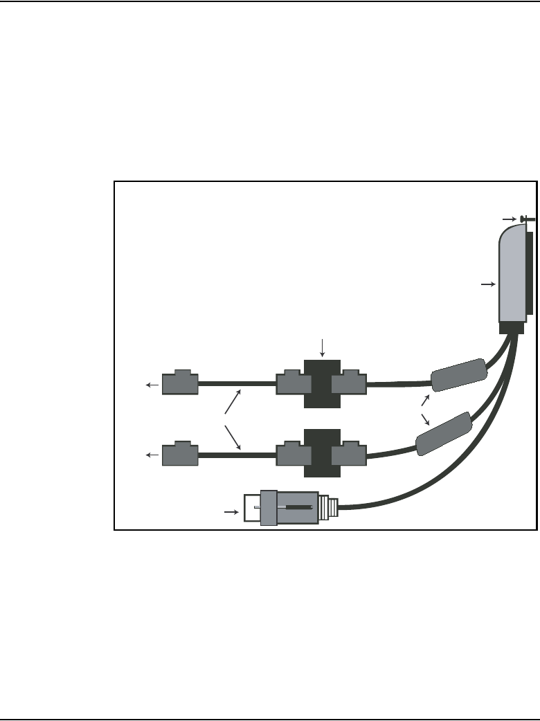
Installation and initial configuration of an IP Telephony node Page 331 of 910
IP Line Description, Installation and Maintenance
Install the NTMF94EA ELAN, TLAN, RS-232 Serial Maintenance
I/O interface cable
The NTMF94EA cable provides the ELAN, TLAN and serial interface for the
ITG-P 24-port line card. See Appendix B: “I/O, maintenance, and
extender cable description” on page 857 for pinouts and technical
specifications on the NTMF94EA cable.
Figure 67
NTMF94EA ELAN, TLAN, and RS-232 Serial Maintenance I/O cable
Mounting Screw
Shielded 25-pair
Amphenol Connector
Shielded RJ-45
Mating Coupler
Shielded RJ-45 Cable
Ferrite
9 Pin D-Sub
Female
To Switch
To Switch
553-ITG0006
Page 332 of 910 Installation and initial configuration of an IP Telephony node
553-3001-365 Standard 4.00 August 2005
To install the NTMF94EA ELAN, TLAN, serial interface cable, complete the
steps in Procedure 18.
Procedure 18
Installing the NTMF94EA ELAN, TLAN, serial interface cable
1On Large Systems, connect the NTMF94EA ELAN, TLAN, and RS-232
Serial Maintenance I/O cable to the I/O panel connector for the left hand
card slot.
For Small Systems, connect the cable to the I/O connector in the cabinet
that corresponds to the IP Line card slot (see Figure 276 on page 859).
2Connect a shielded CAT5 Ethernet cable from the customer’s TLAN
Layer 2 or Layer 3 switch port to the RJ-45 port labeled “TLAN”.
3Connect a shielded CAT5 Ethernet cable from the customer’s ELAN
Layer 2 or Layer 3 switch port to the RJ-45 port labeled “ELAN”.
4Install the NTAG81CA serial cable into the faceplate Maintenance port.
This connection is used to configure the IP address for Leader 0. If
required, use the NTAG81BA maintenance extender cable.
Note: Alternatively, for a permanent connection to the maintenance port,
use the DB9 female connector on the NTMF94BA breakout cable to
connect a modem (using a null modem) or directly to a local TTY terminal.
WARNING
Plug all Voice Gateway Media Card ELAN network
interfaces belonging to the same node into the same
ELAN hub or Layer 2 switch port group.
WARNING
The serial maintenance ports presented at the faceplate
and at the backplane are identical. Do not connect a
terminal to both access points simultaneously. This
results in incorrect and unpredictable operation of the
Voice Gateway Media Card.

Installation and initial configuration of an IP Telephony node Page 333 of 910
IP Line Description, Installation and Maintenance
Note 1: The switch LEDs and the faceplate link LEDs light when the card
is connected to the WAN/LAN through the TLAN network interface.
Note 2: Refer to Converging the Data Network with VoIP (553-3001-160)
for more information about engineering and connecting the LAN/WAN.
End of Procedure
Install the Shielded 50-pin to Serial/ELAN/TLAN Adapter
The Media Card can support a single connector solution for access to the
TLAN and ELAN network interfaces. This connector (see Figure 68 on
page 334) is called the A0852632 Shielded 50-pin to Serial/ELAN/TLAN
Adapter. It replaces the single NTMF94EA ELAN, TLAN, RS-232 Serial
Maintenance I/O interface cable (‘octopus’ cable).
The adapter breaks out the signals from the I/O connector to the following:
• ELAN network interface
• TLAN network interface
• one RS-232 (local console) port

Page 334 of 910 Installation and initial configuration of an IP Telephony node
553-3001-365 Standard 4.00 August 2005
Figure 68
Shielded 50-pin to Serial/ELAN/TLAN Adapter
On Large Systems, the NT8D81AA cable is used to bring all 24 Tip and Ring
pairs to the I/O panel. The NTCW84JA I/O panel mounting block must be
installed on Large Systems before the A0852632 Shielded 50-pin to
Serial/ELAN/TLAN Adapter is installed. Refer to Figure 68.
To ensure proper connection, install the adapter securely; otherwise,
connectivity could be lost.
Identification Label
TLAN RJ-45
port ELAN RJ-45 port RS-232 Connector
50-pin connector
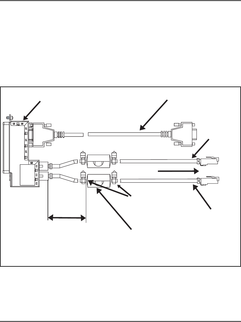
Installation and initial configuration of an IP Telephony node Page 335 of 910
IP Line Description, Installation and Maintenance
EMC Shielding Kit
An ITG EMC shielding kit (NTVQ83AA) must be installed on the ELAN and
TLAN network interface cables to meet regulatory requirements at the
installation site. As shown in Figure 69, a ferrite must be placed on both the
ELAN and TLAN network interface CAT5 Ethernet cables during
installation. Cable ties are then placed to retain the ferrites in the correct
position. This applies to Small Systems and Large Systems.
Figure 69
ITG EMC Shielding Kit Deployment
Follow the steps in Procedure 19 on page 336 to install the ITG EMC
shielding kit (NTVQ83AA) on the ELAN and TLAN network interface
cables.
EMC Kit Deployment
Serial/maintenance cable
ELAN
cable
To LAN/hub
TLAN
cable
cable tie
snap-on ferrite
3 in
ITG Card Adapter ELAN/TLAN

Page 336 of 910 Installation and initial configuration of an IP Telephony node
553-3001-365 Standard 4.00 August 2005
Procedure 19
Installing the Shielded 50-pin to Serial/ELAN/TLAN Adapter onto the
Media Card
1Install the Shielded 50-pin to Serial/ELAN/TLAN Adapter into the card
connector (1, 2, 3, or 4) where the Media Card is located.
2Connect a shielded Cat 5 cable from the customer’s TLAN switch
equipment to the port labeled “TLAN”.
3Connect a shielded Category 5 cable from the customer’s ELAN hub or
switch equipment to the port labeled “ELAN”.
4Install the NTAG81CA serial cable into the faceplate Maintenance port.
End of Procedure
Initial configuration of IP Line 4.5 data
Before beginning the configuration:
• Ensure the system is running CS 1000 Release 4.5 software.
• Verify the License system limit in LD 22. The License system limit must
have sufficient unused units to support the number of IP Phones to be
installed. For more information, refer to Software Input/Output:
Maintenance (553-3001-511).
• Expand the License limit, if necessary, by ordering additional Licenses.
See “Licenses” on page 64 for more information.
Summary of procedures
1Configure IP address for the system active ELNK Ethernet network
interface (LD 117). See page 337.
2Configure VoIP bandwidth management zones (LD 117). See page 338.
3Configure physical TNs (LD 14). See page 342.
4Configure virtual superloops for IP Phones. See page 347.
5Configure IP Phone features in LD 11. See page 351.

Installation and initial configuration of an IP Telephony node Page 337 of 910
IP Line Description, Installation and Maintenance
Configure IP address for the system active
ELNK Ethernet network interface (LD 117)
To configure the Call Server’s ELAN network interface IP address (active
ELNK), follow the steps in Procedure 20.
Procedure 20
Configuring the ELAN network interface IP address for the active ELNK
1Go to LD 117.
2Create host entries with the IP address on the ELAN subnet by entering
one of the following commands:
NEW HOST PRIMARY_IP xx.xx.xx.xx
NEW HOST SECONDARY_IP xx.xx.xx.xx (for Large Systems only)
3Assign the host entry IP address to active and inactive ELNK interfaces
on the ELAN subnet by entering one of the following commands:
CHG ELNK ACTIVE PRIMARY_IP
CHG ELNK INACTIVE SECONDARY_IP (for Dual CPU only)
4Verify the IP address for the Ethernet network interface by entering the
following command: PRT ELNK.
5Enter the following command: Update DBS.
6Go to LD 137. Check the status of the Ethernet network interface by
entering the command: STAT ENLK. If the ELNK network interface is
disabled, enable it by entering: ENL ELNK.
End of Procedure
Page 338 of 910 Installation and initial configuration of an IP Telephony node
553-3001-365 Standard 4.00 August 2005
Configure VoIP bandwidth management zones (LD 117)
Up to 256 zones can be defined in LD 117. The Call Server uses the zones for
VoIP bandwidth management. For more information, see Converging the
Data Network with VoIP (553-3001-160).
The term Intrazone means within the same zone. Interzone means between
two different zones.
Table 64 on page 339 lists the zone parameters as follows:
• p1 – total bandwidth (Kbps) available for Intrazone calls
• p2 – defines the codec for Intrazone calls (that is, preserve voice quality
or preserve bandwidth). BQ provides the best voice quality but uses the
most bandwidth. BB uses the least amount of bandwidth but reduces
voice quality.
• p3 – total bandwidth available for Interzone calls
• p4 – preferred strategy for the choice of the codec for Interzone calls
• p5 – zone resource type. The type is either shared or private.
LD 117 also includes the DIS and ENL commands to disable or enable a
zone. When a zone is created, its default state is enabled.
CAUTION
Zone 0 must be configured in LD 117 first before other
zones are configured or all calls associated with zone 0
are blocked.

Installation and initial configuration of an IP Telephony node Page 339 of 910
IP Line Description, Installation and Maintenance
Table 64
LD 117 bandwidth management zone configuration
Command Description
NEW ZONE xxx p1 p2 p3 p4 p5 Create a new zone, where:
xxx = zone number = (0) – 255.
p1 = Intrazone available bandwidth
= 0 – (10000) – 100000 (Kbps)
p2 = Intrazone preferred strategy
= (BQ – Best Quality) or BB – Best Bandwidth
p3 = Interzone available bandwidth
= 0 – (10000) – 100000 (Kbps)
p4 = Interzone preferred strategy
= BQ for Best Quality or BB for Best Bandwidth
p5 = Zone resource type
= (shared) or private
New ZONE xxx Create a new zone with default values for the parameters:
p1 = 10000 (Kbps)
p2 = BQ
p3 = 10000 (Kbps)
p4 = BQ
p5 = shared
CHG ZONE xxx p1 p2 p3 p4 p5 Change parameters of a zone. All parameters must be
re-entered, even those that are unchanged.
OUT ZONE xxx Remove a zone.
DIS ZONE xxx Disable a zone. When a zone is disabled, no new calls
are established inside, from, or toward this zone.
ENL ZONE xxx Enable a zone.
PRT ZONE xxx
PRT ZONE ALL
Print zone and bandwidth information, where xxx
specifies a zone. If no zone is specified, information for all
zones is printed. PRT ZONE ALL also prints information
for all zones.
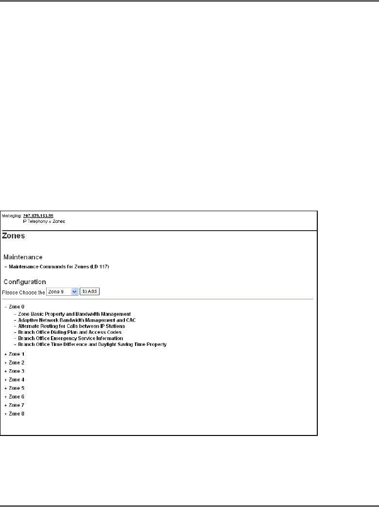
Page 340 of 910 Installation and initial configuration of an IP Telephony node
553-3001-365 Standard 4.00 August 2005
Element Manager for Zone Configuration
Optionally, zones can be configured for CS 1000 systems using Element
Manager instead of LD 117.
To view Element Manager for zone configuration, follow the steps in
Procedure 22:
Procedure 21
Viewing Element Manager for Zone Configuration
1Launch and log into Element Manager. See Procedure 25 on page 367.
2In the navigator, click IP Telephony > Zones.
The Zones window opens. See Figure 70.
Figure 70
Zone List
3Under Configuration, click the to Add button to add a new zone.
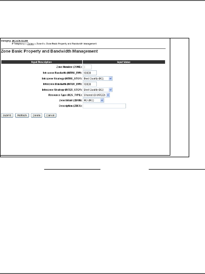

Page 342 of 910 Installation and initial configuration of an IP Telephony node
553-3001-365 Standard 4.00 August 2005
Configure physical TNs (LD 14)
Use LD 14 to define the physical TNs for the Voice Gateway Media Card.
Also use LD 14 to disable the cards. The OTM IP Telephony Gateway - IP
Line application requires Voice Gateway Media Cards to be in a disabled
state before transmitting card properties.
See Table 65 for a list of the prompts and responses in LD 14.
Table 65
Configure physical TNs in LD 14
Prompt Response Description
REQ NEW
CHG
OUT
Create the Voice Gateway channels on a line card.
Change configuration data for a Voice Gateway channel.
Delete the Voice Gateway channels on a line card.
TYPE VGW Voice Gateway
TN
l s c u
c u
TN of the first ITG Physical TN
Format for Large System and CS 1000E system, where l = loop,
s = shelf, c = card, u = unit.
Format for Small System, CS 1000S system, Media Gateway
1000B, and Media Gateway 1000T, where c = card and u = unit.
DES aa.......a Description for gateway channel.
Identify the channel using the card’s TLAN network interface
IP address or MAC address.
XTRK aaa ITG8 – ITG 486 8-port card
ITGP – ITG-P 24-port card
MC8 – Media Card 8-port card
MC32 – Media Card 32-port card
ZONE 0 – 255 Zone number to which this ITG Physical TN belongs.
Verify that the zone exists in LD 117.
CUST xx Customer number as defined in LD 15
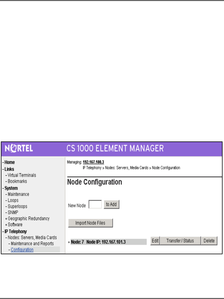
Installation and initial configuration of an IP Telephony node Page 343 of 910
IP Line Description, Installation and Maintenance
Using Element Manager for Voice Gateway channels
Alternatively, for CS 1000 systems, configure the Voice Gateway channels
using Element Manager instead of using LD 14.
To use Element Manager to configure Voice Gateway channels, follow the
steps in Procedure 22.
Procedure 22
Using Element Manager to configure Voice Gateway channels
1Launch and log into Element Manager. See Procedure 25 on page 367
for details.
2In the navigator, click IP Telephony > Nodes: Servers, Media Cards >
Configuration.
The Node Configuration window opens. See Figure 72.
Figure 72
Node Configuration window
3Expand a node by clicking the plus sign (+) to the left of the node.
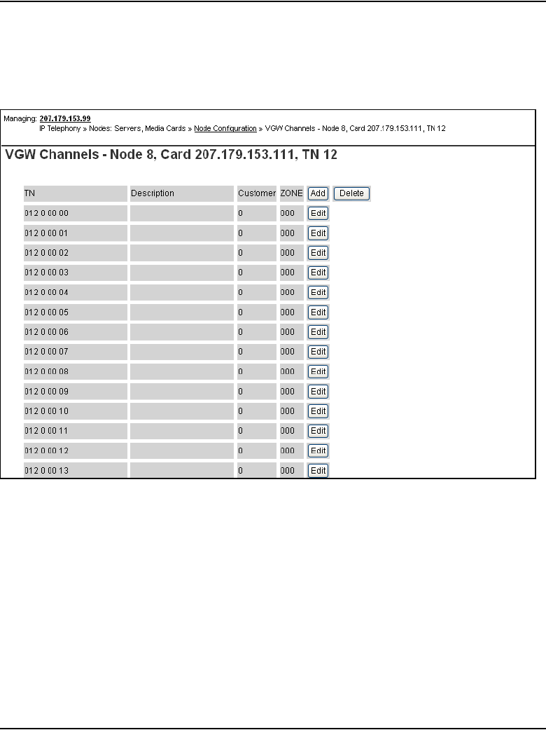
Page 344 of 910 Installation and initial configuration of an IP Telephony node
553-3001-365 Standard 4.00 August 2005
4Click the VGW Channels button next to the card to be configured.
The VGW Channels window opens. See Figure 73.
Figure 73
VGW Channels summary window
5To add new gateway channels, click the Add button at the top in the VGW
Channels window.
The Add VGW channels window opens. See Figure 74 on page 345.
Note: Figure 74 is the equivalent to LD 14’s NEW command.
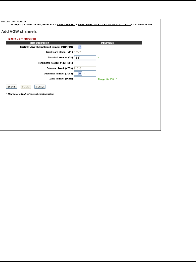
Installation and initial configuration of an IP Telephony node Page 345 of 910
IP Line Description, Installation and Maintenance
Figure 74
Add VGW channels window
6To edit a specific Voice Gateway channel, click the Edit button to the right
of the channel in the VGW Channels window seen in Figure 73 on page
344.
The Edit VGW channel window opens. See Figure 75 on page 346.
Note: The Edit VGW channel window is equivalent to LD 14’s CHG
command that enables the changing of the DES and ZONE parameters
of the channel.
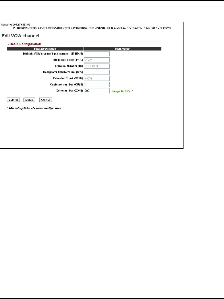
Page 346 of 910 Installation and initial configuration of an IP Telephony node
553-3001-365 Standard 4.00 August 2005
Figure 75
Edit VGW channel window
7To delete a Voice Gateway channel, click the Delete button in the
Gateway Channel summary window. See Figure 73 on page 344.
The Delete VGW channels for the Voice Gateway channel opens. See
Figure 76 on page 347.
Select a gateway channel from the drop-down list box and click Delete.
Note: Figure 76, the Delete VGW channels window, is the equivalent of
LD 14’s OUT command.
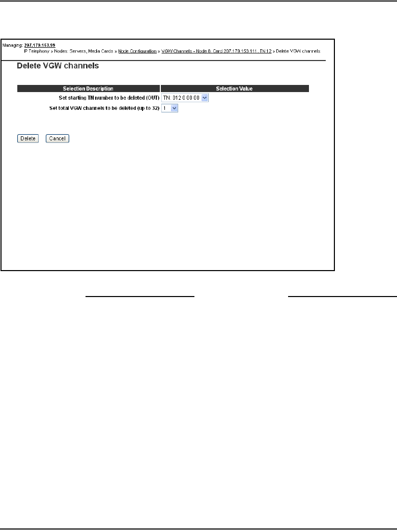
Installation and initial configuration of an IP Telephony node Page 347 of 910
IP Line Description, Installation and Maintenance
Figure 76
Delete VGW channels window
End of Procedure
Configure virtual superloops for IP Phones
One or more virtual superloops must be configured to support IP Phone
Virtual TNs (VTNs) in LD 97 or in Element Manager. To create the virtual
superloop in Element Manager, click System > Superloops in the Element
Manager navigator.
Large Systems and CS 1000E
In Large Systems and CS 1000E, virtual superloops contend for the same
range of loops with phantom, standard and remote superloops, digital trunk
loops, and all service loops. Virtual superloops can reside in
physically-equipped network groups or in virtual network groups.

Page 348 of 910 Installation and initial configuration of an IP Telephony node
553-3001-365 Standard 4.00 August 2005
Group maximums
Without FIBN, Package 365, there is a maximum of five network groups
available, 0 – 4. With Package 365, there are a maximum of eight network
groups, 0 – 7.
For normal traffic engineering, provision up to 1024 VTNs on a single virtual
superloop for a Large System/CS 1000E. For non-blocking, do not exceed
120 VTNs on a single virtual superloop for a Large System/CS 1000E.
Nortel recommends that virtual superloops are configured starting in the
highest non-physically equipped group available. Table 66 lists the prompts
and responses required to configure virtual superloops in LD 97.
Small Systems
In Small Systems, virtual superloops contend for the same range of
superloops, 96 – 112, with phantom superloops.
Up to 128 VTNs can be configured on a single virtual superloop for a
Meridian 1 Option 11C Cabinet and Option 11C Chassis system, for a
maximum of 640 VTNs in each system.
Table 66
LD 97 – Virtual superloop configuration for Large Systems /CS 1000E
Prompt Response Description
REQ CHG Change existing data.
TYPE SUPL Superloop
SUPL Vxxx V represents a virtual superloop and xxx is the number of
the virtual superloop where:
• xxx = 0 – 156 and multiple of four for a Large System
without FIBN package 365
• xxx = 0 – 252 and multiple of four for a Large System
with FIBN package 365

Installation and initial configuration of an IP Telephony node Page 349 of 910
IP Line Description, Installation and Maintenance
A maximum of 1000 VTNs can be configured on a CS 1000M Cabinet and
CS 1000M Chassis system.
In a Small System, mapping virtual superloops to virtual cards is the same as
mapping phantom superloops to phantom cards. See Table 67.
CS 1000S systems
Table 68 lists the virtual superloop and virtual card mapping for the
CS 1000S system.
LD 97 PRT TYPE SUPL prints the implicit virtual, phantom, or DECT cards
for a virtual, phantom, or DECT superloop.
Table 67
Virtual superloop/virtual card mapping for Small Systems
SUPL Card
96 61-64
100 65-68
104 69-72
108 73-76
112 77-80
Table 68
Virtual superloop/virtual card mapping for CS 1000S systems
SUPL Card
96 61-64 81-84
100 65-68 85-88
104 69-72 89-92
108 73-76 93-96
112 77-80 97-99
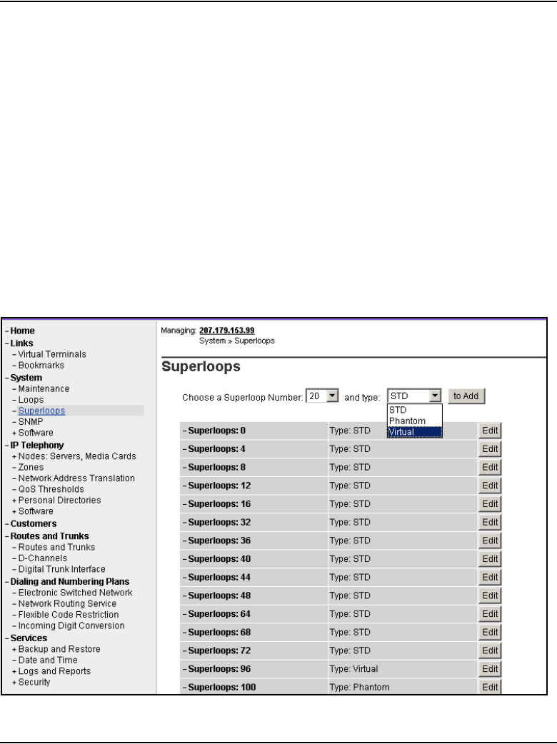
Page 350 of 910 Installation and initial configuration of an IP Telephony node
553-3001-365 Standard 4.00 August 2005
LD 21 LUU allows the user to list unused units of a specified type (iset, vtrk,
phantom, DECT) in a specified range of TNs (for example, Virtual TNs).
Similarly, LUC of a specified type (virtual, phantom, or DECT) prints a list
of unused cards on configured superloops.
Configuring virtual superloops in Element Manager
To configure a virtual superloop in Element Manager, follow the steps in
Procedure 23.
Procedure 23
Configuring a virtual Superloop in Element Manager
1In the Element manager navigator, click System > Superloops.
The Superloops window opens. See Figure 77.
Figure 77
Configuring a virtual superloop in Element Manager

Installation and initial configuration of an IP Telephony node Page 351 of 910
IP Line Description, Installation and Maintenance
2Select the superloop number from the Choose a Superloop Number
drop-down list.
3Select Virtual from the type drop-down list.
4Click to Add.
End of Procedure
Configure IP Phone features in LD 11
The existing License header that is printed at the start of LD 11 includes the
new License limit for the IP Phone. Refer to Table 58 on page 308 to
configure the IP Phone features in LD 11.
Table 69
LD 11 – Configure an IP Phone (Part 1 of 3)
Prompt Response Description
REQ: NEW
CHG
PRT
OUT
CPY
MOV
New
Change
Print
Out
Copy
Move
TYPE: i2001
i2002
i2004
i2050
For IP Phone 2001, IP Phone 2002, and IP Phone 2004,
IP Softphone 2050, or MVC 2050. The system accepts
this response if it is equipped with packages 88 and 170.
The IP Phones are also restricted by the IP Phone
License setting.
Note: The IP Phone 2007 is type i2004. The IP Audio
Conference Phone 2033 is type i2001.

Page 352 of 910 Installation and initial configuration of an IP Telephony node
553-3001-365 Standard 4.00 August 2005
TN l s c u
c u
Format for Large System and CS 1000E system, where
l = loop, s = shelf, c = card, u = unit.
Enter loop (virtual loop), shelf, card, and unit (terminal
number),
where unit = 0 – 31
Format for Small System, CS 1000S system, Media
Gateway 1000B, and Media Gateway 1000T, where c =
card and u = unit.
Enter card slot (virtual slot) and unit.
Note: See Table 67 on page 349 for virtual superloop to
virtual card slot mapping for Small Systems.
DES a...z ODAS telephone designator
CUST xx Customer number as defined in LD 15
ZONE 0 – 255 Zone number to which this IP Phone belongs. The zone
prompt is applied only when TYPE = i2001, i2002, i2004,
or i2050.
Note: Verify that the zone number exists in LD 117.
Table 69
LD 11 – Configure an IP Phone (Part 2 of 3)
Prompt Response Description

Installation and initial configuration of an IP Telephony node Page 353 of 910
IP Line Description, Installation and Maintenance
Configure the IP Phone KEM
Configure the optional IP Phone KEM in LD 11.
CLS ADD ADD - Automatic Digit Display, default for IP Phone.
For a complete list of responses, refer to Software
Input/Output: Administration (553-3001-311).
KEY xx aaa yy
zz...zz
Telephone function key assignments where:
xx = keys 0 – 5 (and 6 – 11 using the Shift key) for IP
Phone 2004 and xx = keys 0 – 3 for the IP Phone 2002.
These are self-labeled physical keys that can be
programmed with any feature. xx = 0 for the IP Phone
2001; any other key number entered returns an error
message.
aaa = key name or function
yyy, zzz = additional information required for the key.
Note: Keys 16 – 26 are reserved for dedicated IP
Phone soft keys.
Table 70 lists the dedicated IP Phone key name values
(aaa). Other key name values can be found in Software
Input/Output: Administration (553-3001-311).
Table 69
LD 11 – Configure an IP Phone (Part 3 of 3)
Prompt Response Description

Page 354 of 910 Installation and initial configuration of an IP Telephony node
553-3001-365 Standard 4.00 August 2005
Note: The IP Phone KEM is not supported on the IP Phone 2001,
IP Phone 2007, or IP Audio Conference Phone 2033.
LD 11 – Configure the IP Phone KEM. (Part 1 of 4)
Prompt Response Description
REQ: NEW
CHG
Add new data.
Change existing data.
TYPE: i2002
i2004
IP Phone 2002
IP Phone 2004
...
ZONE 0-255 Zone number to which the IP Phone 2002 or
IP Phone 2004 belongs
KEM (0)-2 Number of attached IP Phone KEMs
Note: Up to two IP Phone KEMs can be attached to an
IP Phone. Pressing <CR> without entering a number
leaves the value unchanged.
...

Installation and initial configuration of an IP Telephony node Page 355 of 910
IP Line Description, Installation and Maintenance
KEY xx aaa yyyy (cccc or D) zz..z
Telephone function key assignments
The following key assignments determine calling options
and features available to a telephone. Note that KEY is
prompted until just a carriage return <CR> is entered.
Where:
xx = key number
For IP Phone 2002, where:
xx = 0-31, when KEM = 0
xx = 0-55, when KEM = 1
xx = 0-79, when KEM = 2
For IP Phone 2004, where:
xx = 0-31, when KEM = 0
xx = 0-79, when KEM = 1
xx = 0-79, when KEM = 2
Note: Type xx = NUL to remove a key function or
feature.
aaa = key name or function
yyyy = additional information required for the key
zz..z = additional information required for the key aaa
The cccc or D entry deals specifically with the Calling
Line Identification feature, where:
cccc = CLID table entry of (0)-N, where N = the value
entered at the SIZE prompt in LD 15 minus 1. You can
enter a CLID table entry if aaa = ACD, HOT d, HOT L,
MCN, MCR, PVN, PVR, SCN, or SCR.
D = the character “D”. When the character “D” is
entered, the system searches the DN keys from key 0
and up, to find a DN key with a CLID table entry. The
CLID associated with the found DN key will then be
used.
LD 11 – Configure the IP Phone KEM. (Part 2 of 4)
Prompt Response Description

Page 356 of 910 Installation and initial configuration of an IP Telephony node
553-3001-365 Standard 4.00 August 2005
Note: The position of the (cccc or D) field varies
depending on the key name or function.
PAG E O F S T <Page>
<KeyOffset>
Automatically calculates the IP Phone KEM key based
on the entered values. This prompt enables the system
administrator to enter a Page number of 0 or 1 and a Key
Offset number from 0-23. Once entered, the KEY
prompt is prompted with the appropriate KEY value filled
in.
Enter <CR> to terminate data entry.
Note 1: Applies to an IP Phone 2004 with
KEM = 1, and where <CR> was entered at the KEY
prompt.
Note 2: Does not apply to an IP Phone 2002.
When values are entered for Page and KeyOffset, the
KEY xx prompt displays, followed by PAGEOFST
prompt. This loop continues until no values (<CR> only)
are entered at the PAGEOFST prompt.
KEY xx Edit the IP Phone KEM key number specified by
PAGEOFST, where:
xx = the number of the key (for example, KEY 36)
Enter <CR> to keep the current setting.
LD 11 – Configure the IP Phone KEM. (Part 3 of 4)
Prompt Response Description

Installation and initial configuration of an IP Telephony node Page 357 of 910
IP Line Description, Installation and Maintenance
KEMOFST <KEM>
<KeyOffset>
Automatically calculates the IP Phone KEM key based
on the entered values. This prompt enables the system
administrator to enter a KEM number of 1 or 2 and a Key
Offset number from 0-23. Once entered, the KEY
prompt is prompted with the appropriate KEY value filled
in.
Enter <CR> to terminate data entry.
When values are entered for KEM and KeyOffset, the
KEY xx prompt displays, followed by KEMOFST prompt.
This loop continues until no values (<CR> only) are
entered at the KEMOFST prompt.
Note 1: Applies to an IP Phone 2002 if <CR> was
entered at the KEY prompt.
Note 2: Applies to an IP Phone 2004 with
KEM = 2, and where <CR> was entered at the KEY
prompt.
KEY xx Edit the IP Phone KEM key number specified by
KEMOFST, where:
xx = the number of the key (for example, KEY 36)
Enter <CR> to keep the current setting.
LD 11 – Configure the IP Phone KEM. (Part 4 of 4)
Prompt Response Description

Page 358 of 910 Installation and initial configuration of an IP Telephony node
553-3001-365 Standard 4.00 August 2005
IP Phone dedicated soft keys
Table 70 describes the features that can be assigned to dedicated soft keys
16-26 on the IP Phone 2001, IP Phone 2002, IP Phone 2004, IP Phone 2007,
IP Phone Audio Conference 2033, IP Softphone 2050, or MVC 2050.
Remove unused feature keys by configuring the dedicated soft keys to NUL.
Some features depend on the given Class of Service.
If an attempt is made to configure anything other than the permitted response,
the system generates an error code. For related error messages, see SCH
messages in Software Input/Output: System Messages (553-3001-411).
Table 70
LD 11 – IP Phone dedicated soft key assignment (Part 1 of 2)
IP Phone
key number Response(s) Allowed
Key 16 MWK, NUL
MWK – Message Waiting key
Key 17 TRN, NUL
TRN– - Call Transfer key
Key 18 A03, A06, NUL
AO3 – 3-party conference key
AO6 – 6-party conference key
Key 19 CFW, NUL
CFW – Call Forward key
Key 20 RGA, NUL
RGA – Ring Again key
Key 21 PRK, NUL
PRK – Call Park key
Key 22 RNP, NUL
RNP – Ringing Number pickup key

Installation and initial configuration of an IP Telephony node Page 359 of 910
IP Line Description, Installation and Maintenance
Node election rules
The rules for the node election process are as follows:
1A Signaling Server wins over any Voice Gateway Media Cards.
2A Leader card always wins over a Follower card.
3A Media Card wins over an ITG-P card.
4Within each class (Leader/Follower), the card with the longest up-time
wins.
5In the event of a tie in up-time length, the card with the lowest IP address
wins.
The precedence of the rules is from 1 (highest) to 5 (lowest). This means, for
example, that since Rule 2 is applied before Rule 3, a Media Card Follower
card cannot win over an ITG-P Leader card.
Key 23 SCU, SSU, SCC, SSC, NUL
SCU – Speed Call User
SSU – System Speed Call User
SCC – Speed Call Controller
SSC – System Speed Call Controller
Key 24 PRS, NUL
PRS – Privacy Release key
Key 25 CHG, NUL
CHG – Charge Account key
Key 26 CPN, NUL
CPN – Calling Party Number key
Table 70
LD 11 – IP Phone dedicated soft key assignment (Part 2 of 2)
IP Phone
key number Response(s) Allowed

Page 360 of 910 Installation and initial configuration of an IP Telephony node
553-3001-365 Standard 4.00 August 2005

Page 361 of 910
IP Line Description, Installation and Maintenance
452
Configuration of IP Telephony nodes
using Element Manager
Contents
This section contains information on the following topics:
Introduction . . . . . . . . . . . . . . . . . . . . . . . . . . . . . . . . . . . . . . . . . . . . . . 362
Upgrade the ITG-P 24-port line cards to IP Line 4.5. . . . . . . . . . . . 363
Configure IP Line 4.5 data using Element Manager. . . . . . . . . . . . . . . 363
Internet Explorer browser configuration . . . . . . . . . . . . . . . . . . . . . 364
Launch Element Manager. . . . . . . . . . . . . . . . . . . . . . . . . . . . . . . . . 366
Summary of procedures . . . . . . . . . . . . . . . . . . . . . . . . . . . . . . . . . . 369
Manually add an IP Telephony node . . . . . . . . . . . . . . . . . . . . . . . . 370
Configure SNMP trap destinations and community name string access . . . . . 375
Configure Voice Gateway Profile data. . . . . . . . . . . . . . . . . . . . . . . 379
Configure Quality of Service . . . . . . . . . . . . . . . . . . . . . . . . . . . . . . 385
Configure ELAN IP address (Active ELNK), TLAN voice
port, and routes (Small Systems and CS 1000S only). . . . . . . . . . . . . . . . . 387
Configure file server access . . . . . . . . . . . . . . . . . . . . . . . . . . . . . . . 392
Configure loss and level plan . . . . . . . . . . . . . . . . . . . . . . . . . . . . . . 394
Add card and configure the card properties of the
Voice Gateway Media Card . . . . . . . . . . . . . . . . . . . . . . . . . . . . . . . 395
Submit and transfer the node information . . . . . . . . . . . . . . . . . . . . 398
Transfer node configuration from Element Manager to
the Voice Gateway Media Cards. . . . . . . . . . . . . . . . . . . . . . . . . . . . . . 401
Configuring the Leader network interface IP address . . . . . . . . . . . 402
Transmit node properties . . . . . . . . . . . . . . . . . . . . . . . . . . . . . . . . . 405
Configure the Follower cards . . . . . . . . . . . . . . . . . . . . . . . . . . . . . . 411

Page 362 of 910 Configuration of IP Telephony nodes using Element Manager
553-3001-365 Standard 4.00 August 2005
Upgrade the Voice Gateway Media Card software and IP Phone firmware . . . . . 415
IP Phone firmware requirements . . . . . . . . . . . . . . . . . . . . . . . . . . . 416
Default location of firmware files . . . . . . . . . . . . . . . . . . . . . . . . . . 418
IP Phone firmware upgrade from a new Voice Gateway Media Card . . . . . . . 419
Determine Voice Gateway Media Card software version . . . . . . . . 420
Determine the IP Phone firmware version. . . . . . . . . . . . . . . . . . . . 423
Download the current loadware and IP Phone firmware . . . . . . . . . 424
Upload the loadware and firmware files to the file server. . . . . . . . 425
Upgrade the Voice Gateway Media Card loadware. . . . . . . . . . . . . 427
Reboot the Voice Gateway Media Card . . . . . . . . . . . . . . . . . . . . . 432
Re-enable the Voice Gateway Media Card . . . . . . . . . . . . . . . . . . . 433
Upgrade the IP Phone firmware. . . . . . . . . . . . . . . . . . . . . . . . . . . . 437
Upgrade the Voice Gateway Media Card firmware. . . . . . . . . . . . . 447
Configure Alarm Management to receive IP Line SNMP traps. . . . . . 448
Assemble and install an IP Phone. . . . . . . . . . . . . . . . . . . . . . . . . . . . . 448
Change the default IPL> CLI Shell password . . . . . . . . . . . . . . . . . . . 448
Configure the IP Phone Installer Passwords. . . . . . . . . . . . . . . . . . . . . 448
Import node configuration from an existing node . . . . . . . . . . . . . . . . 449
Introduction
This chapter explains how to configure IP Telephony nodes and Voice
Gateway Media Cards using Element Manager. Element Manager is accessed
using a PC with Internet Explorer 6.0.2600 (or later). The PC must be
connected to a LAN that has access to the Signaling Server’s Node IP
address, either directly or routed through the network.
Note: The ELAN subnet IP address might be required, instead of the
Node IP address, to access the Element Manager login window in secure
environments.
This chapter also provides instruction for transmitting files to Voice Gateway
Media Cards, upgrading card software, and upgrading IP Phone firmware.
Read the information on IP network engineering guidelines in Converging the
Data Network with VoIP (553-3001-160) before installing an IP Telephony
node.

Configuration of IP Telephony nodes using Element Manager Page 363 of 910
IP Line Description, Installation and Maintenance
Upgrade the ITG-P 24-port line cards to IP Line 4.5
Note: Element Manager cannot be used with the Meridian 1 system, as
a Signaling Server is required in the system configuration.
CS 1000 systems require the ITG-P 24-port line cards to be running IP Line
4.5.
Configure IP Line 4.5 data using Element Manager
Element Manager can be used to manually add and configure an IP
Telephony node on CS 1000 systems. Multiple nodes can be configured and
managed from Element Manager.
Node definition
A node is defined as a collection of Signaling Servers and Voice Gateway
Media Cards. Each node in the network has a unique Node ID. This Node ID
is an integer value. A node has only one Primary Signaling Server or Leader
Voice Gateway Media Card. All the other Voice Gateway Media Cards are
defined as Followers.
WARNING
In CS 1000 systems, OTM 2.2 is required to upgrade an
ITG-P 24-port line card running IP Line 2.2 (or earlier) to
IP Line 4.5. Once the card’s software has been upgraded
to IP Line 4.5 using OTM 2.2, configuration,
administration, and maintenance tasks can be performed
using Element Manager.
Refer to “ITG-P 24-port card upgrades” in
Communication Server 1000S: Upgrade Procedures
(553-3031-258) for the procedure to upgrade an ITG-P
24-port line card to IP Line 4.5 software.

Page 364 of 910 Configuration of IP Telephony nodes using Element Manager
553-3001-365 Standard 4.00 August 2005
Note 1: All IP addresses and subnet mask data must be in dotted decimal
format. Convert subnet mask data from Classless Inter-Domain (CIDR)
format. for more information, see “Subnet Mask Conversion from CIDR
to Dotted Decimal Format” on page 901.
Note 2: See Table 57 on page 307 for IP addresses and information
required in this procedure.
Note 3: The following sections discuss how to configure IP Line 4.5
using Element Manager. The following three sections found in the
IP Telephony section of Element Manager are not covered in this NTP:
– SNTP (see IP Peer Networking: Installation and Configuration
(553-3001-213)
– Gatekeeper (see IP Peer Networking: Installation and
Configuration (553-3001-213)
– Signaling Server (see Signaling Server: Installation and
Configuration (553-3001-212)
Internet Explorer browser configuration
Element Manager requires Microsoft Internet Explorer 6.0.2600 (or later).
Element Manager is not supported on the Netscape Navigator browser. The
PC should be a PIII with a 500 MHz processor (at minimum).
Follow the steps outlined in Procedure 24 on page 365 to prevent caching of
web pages by Internet Explorer.
IMPORTANT!
Internet Explorer caching interferes with the Element Manager
application, in that users cannot see real-time changes as they occur.
For this reason, Internet Explorer caching must be turned off.
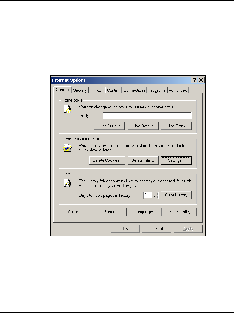
Configuration of IP Telephony nodes using Element Manager Page 365 of 910
IP Line Description, Installation and Maintenance
Procedure 24
Turning off browser caching in Internet Explorer
1Launch Internet Explorer.
2Click Tools > Internet Options.
The Internet Options window opens. See Figure 78.
Figure 78
Internet Explorer – Internet Options
3On the General tab, under the Temporary Internet files section, click the
Settings button.
The Settings window opens. See Figure 79 on page 366.
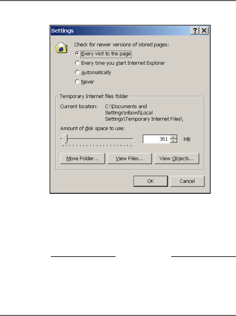
Page 366 of 910 Configuration of IP Telephony nodes using Element Manager
553-3001-365 Standard 4.00 August 2005
Figure 79
Temporary Internet files Settings window
4Click the Every visit to the page radio button.
This checks for new versions of stored pages on every visit to the web
page.
5Click OK in the Settings window.
6Click OK in the Internet Options window.
End of Procedure
Launch Element Manager
Follow the steps in Procedure 25 to launch Element Manager.

Configuration of IP Telephony nodes using Element Manager Page 367 of 910
IP Line Description, Installation and Maintenance
Procedure 25
Launching Element Manager
1Open Internet Explorer.
2Enter the Signaling Server Node IP address in the Address Bar (url line)
of the browser window.
Click Go or press Enter on the keyboard.
Note: The ELAN network interface IP address might be required, instead
of the Node IP address, to access the Element Manager login window in
secure environments.
3Element Manager opens and the Login window appears.
See Figure 80.
a. Enter the User ID and Password of the Call Server.
b. Enter the IP address of the Call Server in the Call Server IP field.
c. Click the Login button.
Figure 80
Element Manager – Login window

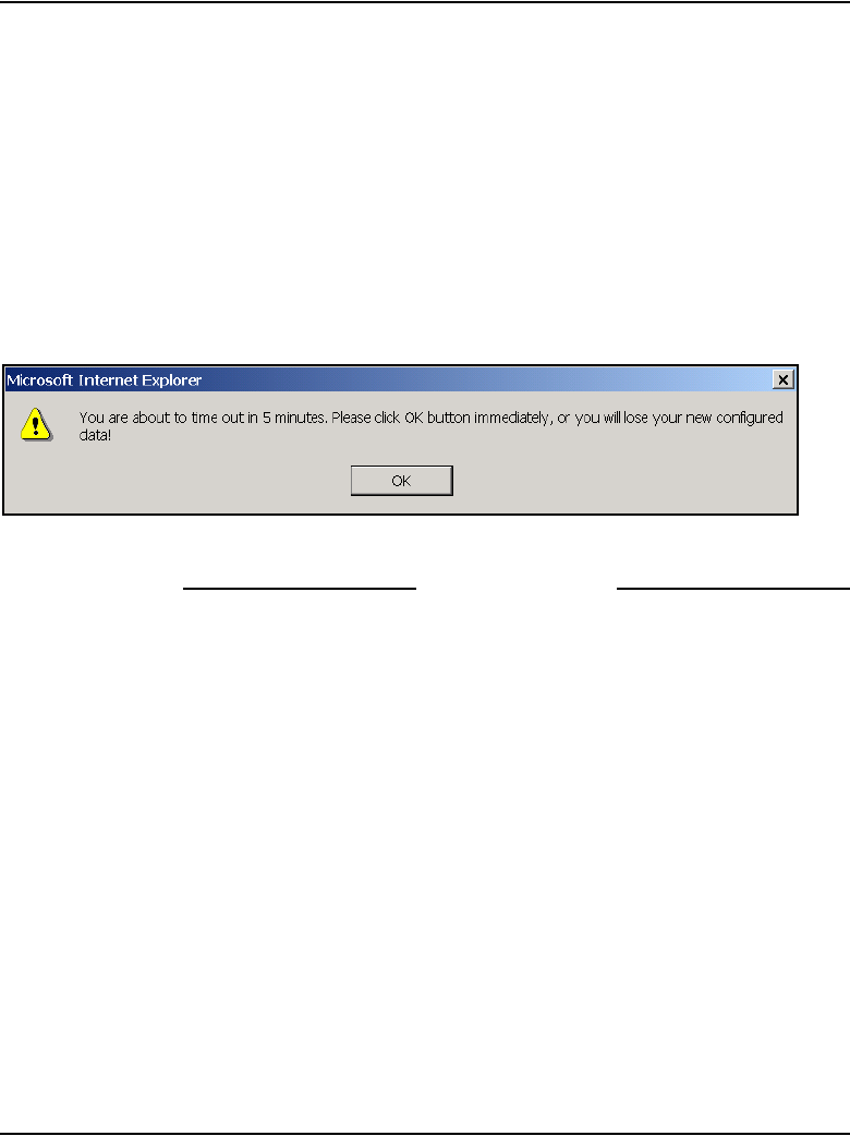
Configuration of IP Telephony nodes using Element Manager Page 369 of 910
IP Line Description, Installation and Maintenance
Note 1: To log out of Element Manager, click Logout in the upper
right-hand corner of the window.
Note 2: When working in the IP Telephony > Node: Servers, Media
Cards > Configuration > Edit window seen in Figure 85 on page 374,
Element Manager times out after a period of inactivity. Users are
prompted with a warning five minutes before Element Manager times out.
If the user clicks OK within the warning time out period, the timer is reset.
If the user does not respond, the session is cancelled and the user is
forced to login again. Any data that was modified, but not submitted, is
lost.
Figure 82
Timeout message
End of Procedure
Summary of procedures
The following is the summary of the steps required to configure a node and a
Voice Gateway Media Card using Element Manager:
1“Manually add an IP Telephony node” on page 370
2“Configure SNMP trap destinations and community name string access”
on page 375
3“Configure Voice Gateway Profile data” on page 379
4“Configure Quality of Service” on page 385
5“Configure ELAN IP address (Active ELNK), TLAN voice
port, and routes (Small Systems and CS 1000S only)” on page 387
6“Configure file server access” on page 392
7“Configure loss and level plan” on page 394
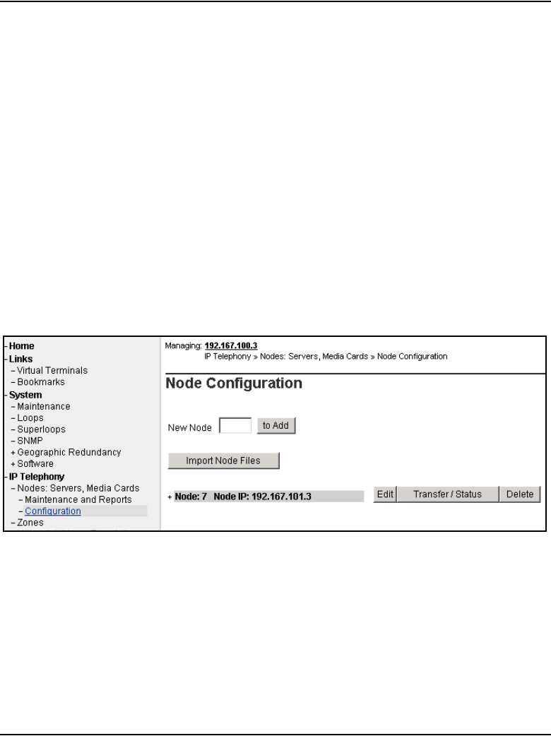
Page 370 of 910 Configuration of IP Telephony nodes using Element Manager
553-3001-365 Standard 4.00 August 2005
8“Add card and configure the card properties of the
Voice Gateway Media Card” on page 395
9“Submit and transfer the node information” on page 398
Manually add an IP Telephony node
Follow the steps in Procedure 26 to add an IP Telephony node using Element
Manager.
Procedure 26
Adding an IP Telephony node manually
1To manually add a new IP Telephony node, click IP Telephony > Node:
Servers, Media Cards > Configuration in the navigator.
The Node Configuration window opens. See Figure 83.
Figure 83
Node Configuration window – Adding a new node

Configuration of IP Telephony nodes using Element Manager Page 371 of 910
IP Line Description, Installation and Maintenance
If this is the first node to be added, the “No nodes are configured”
message is displayed. There are two options: “New Node_ to Add” or
“Import Node Files”.
The Node Configuration window shows a list of all the configured nodes.
To expand a node and view its elements, click the plus sign (+) to the left
of the Node name. Figure 84 on page 372 shows one expanded node.
The Node Configuration window includes five buttons:
•to Add – used to add a new IP Telephony node. Enter an unused
Node ID and then click to Add.
•Import Node Files – imports the configuration files from an existing
node.
•Edit – retrieves the node information from the Call Server and returns
the information to the Edit window. The node information can then be
changed.
•Transfer/Status – used to transfer/obtain the status on the
requested changes to the node. The node then obtains its
information (CONFIG.INI and BOOT.P files) from the Call Server.
Note: If any element within the Node fails to transfer either BOOTP or
CONFIG files, the Transfer/Status button is highlighted in red. If the
transfer status of the node elements is unavailable, the Transfer/Status
button is highlighted in yellow.
•Delete – This button is used to delete the selected node and its
information from the Call Server.
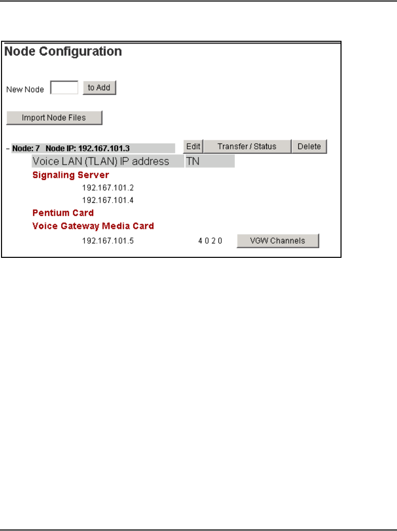
Page 372 of 910 Configuration of IP Telephony nodes using Element Manager
553-3001-365 Standard 4.00 August 2005
Figure 84
Node Configuration window – expand a node
Configuration of IP Telephony nodes using Element Manager Page 373 of 910
IP Line Description, Installation and Maintenance
2Enter the new Node ID in the New Node text box.
The Node ID can be one to four digits in length. When defining the node
number, determine if the Enhanced Redundancy for IP Line Nodes
functionality is required (see “Enhanced Redundancy for IP Line nodes”
on page 251). If it is required, factor the requirement into the node number
assignment process.
Note: The Node ID field corresponds to the Node ID field in the IP Phone
configuration. Write down the node number, which is used during the IP
Phone configuration.
3Click to Add.
The Edit window opens. See Figure 85 on page 374.
CAUTION
The Voice Gateway Media Cards identify themselves
with a node using the node number or node ID. If there
are multiple IP Telephony nodes sharing the same TLAN
subnet, each node must have a unique ID. Each system
on the TLAN subnet must have a unique node ID
assigned to the Voice Gateway Media Cards on the
system.
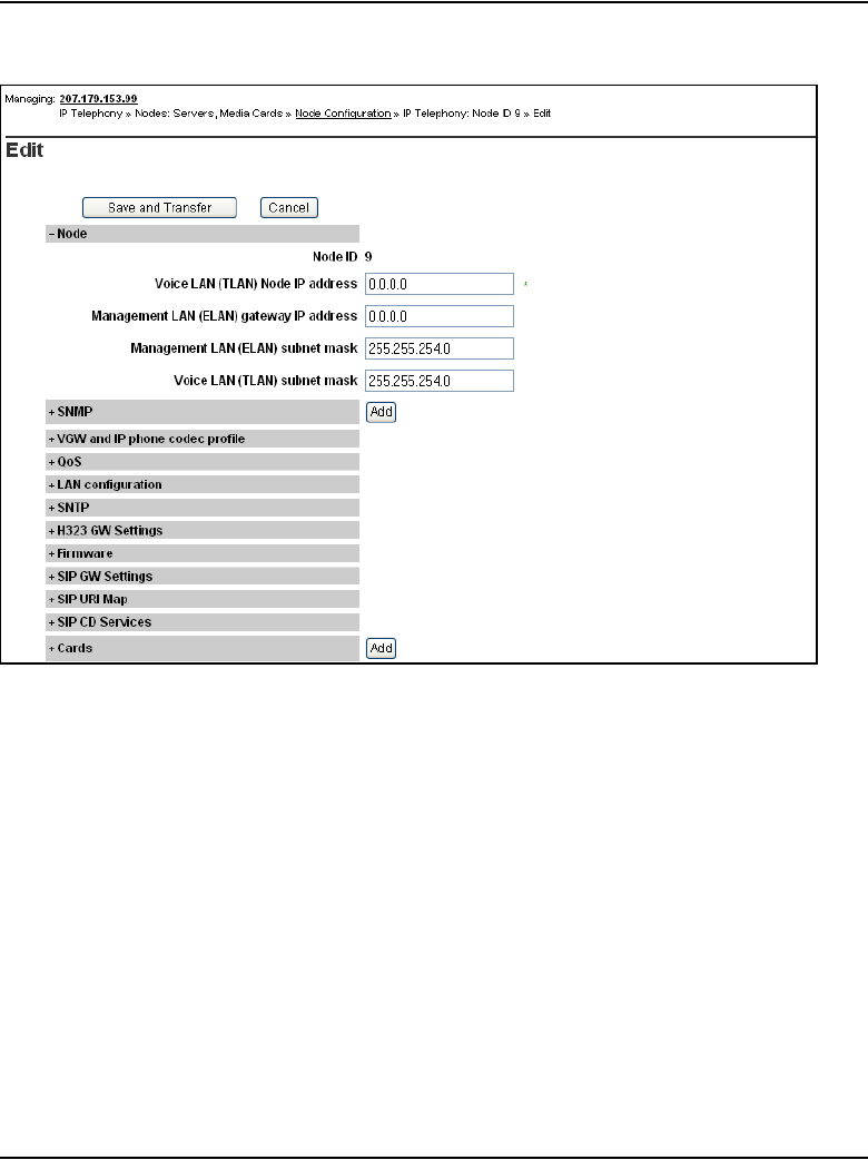
Page 374 of 910 Configuration of IP Telephony nodes using Element Manager
553-3001-365 Standard 4.00 August 2005
Figure 85
Element Manager – Edit
The Edit window includes three different buttons:
•Save and Transfer – saves and transfers changes to the Call Server
and returns the users to the Node Configuration window.
•Cancel – discards changes made to the IP Telephony node and
returns the users to the Node Configuration window.
•Add – associated with specific sections of the IP Telephony node
properties. The user can add new SNMP trap destinations, cards,
and Signaling Servers.
4Click the plus sign (+) to the left of the node name to display the node
information, if it is not already expanded.

Configuration of IP Telephony nodes using Element Manager Page 375 of 910
IP Line Description, Installation and Maintenance
a. Node ID: The node ID entered on the previous page appears.
b. Voice LAN (TLAN) Node IP address: Enter the Voice LAN (TLAN)
Node IP address in dotted decimal format. The Voice LAN Node
IP address is on the TLAN subnet. The Node IP address is the IP
address used by the IP Phones to communicate with the Voice
Gateway Media Cards on the TLAN subnet. If a Voice Gateway
Media Card becomes the primary (Leader) during an election, it
assigns itself the Node IP address.
Note: An asterisk (*) indicates that a field is a required/mandatory field.
c. Management LAN (ELAN) gateway IP address: Enter the
Management LAN (ELAN) subnet gateway IP address in dotted
decimal format. This is the IP address of the gateway of the subnet
to which the Voice Gateway Media Card belongs. Also, this is the IP
address of the router interface on the ELAN subnet, if present. If
there is no Management LAN subnet gateway, enter 0.0.0.0.
d. Management LAN (ELAN) subnet mask: Enter the Management
LAN (ELAN) subnet mask address in dotted decimal format. This is
the subnet mask that is used along with the ELAN subnet IP address
to identify to which subnet the Voice Gateway Media Card belongs.
e. Voice LAN (TLAN) subnet mask: Enter the Voice LAN (TLAN)
subnet mask address in dotted decimal format. This is the subnet
mask that is used along with the TLAN IP address, to identify the
subnet to which the Voice Gateway Media Card belongs.
Note: Do not click Save and Transfer until all the node information has
been entered. If the Submit button is clicked prematurely, the Node
Configuration window reappears. If Save and Transfer was clicked
prematurely, click the Edit button to return to the Node Edit window and
continue the configuration.
End of Procedure
Configure SNMP trap destinations and community name
string access
For more information on SNMP, refer to Simple Network Management
Protocol: Description and Maintenance (553-3001-519).
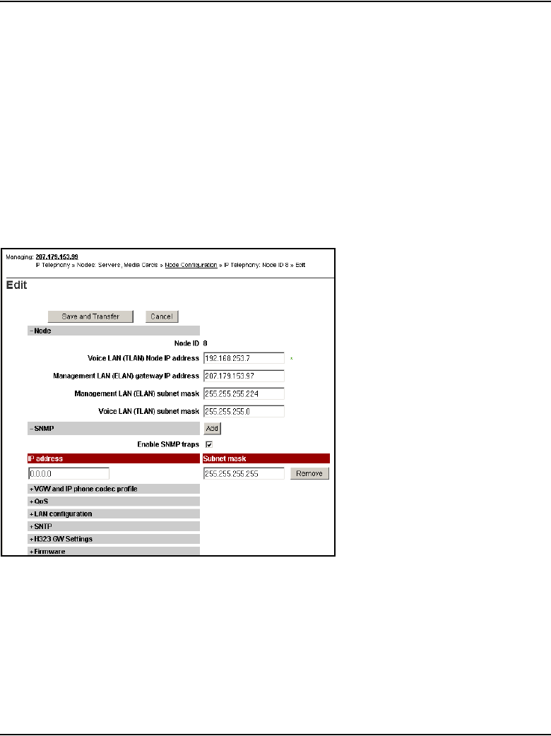
Page 376 of 910 Configuration of IP Telephony nodes using Element Manager
553-3001-365 Standard 4.00 August 2005
Configuring SNMP trap destinations
To configure the SNMP trap destinations for the Signaling Server and Voice
Gateway Media Cards in Element Manager, follow the steps in Procedure 27
on page 376.
Procedure 27
Configuring SNMP trap destinations
1In the Edit window, click the plus sign (+) to the left of SNMP.
See Figure 86.
Figure 86
Node > Edit > SNMP
2Select the Enable SNMP traps check box, if configuring one or more
SNMP management IP addresses to receive SNMP traps from cards in
the IP Telephony node.
f. IP address: Enter the IP address of the trap destination. If SNMP
traps are enabled, the SNMP traps are sent to the IP address entered
here. A maximum of eight trap destination IP addresses can be
configured.

Configuration of IP Telephony nodes using Element Manager Page 377 of 910
IP Line Description, Installation and Maintenance
g. Subnet mask: The subnet mask for the IP address of the trap
destination must always be configured as 255.255.255.255.
h. Click Add to enter the IP address for another trap destination.
Add destination SNMP Manager IP addresses for the following:
• local or remote OTM server
• PPP IP address configured in the router on the ELAN subnet
for the remote-support OTM PC
• SNMP manager for remote alarm monitoring
Note 1: Up to eight SNMP trap destinations can be defined.
Note 2: A net route or host route through the Management (ELAN)
gateway is added to the Voice Gateway Media Cards IP Routing Table for
each SNMP trap destination IP address that is added.
Note 3: To remove an SNMP trap destination, click the corresponding
Remove button.
End of Procedure
Configuring community name strings
The SNMP community name strings control access to the IP Telephony node.
Element Manager uses the community name strings to refresh the Voice
Gateway Media Card status and to control the transmitting and retrieving of
configuration data files for database synchronization.
WARNING
Always configure the trap destination subnet mask as
255.255.255.255. Do not enter the actual value of the
subnet mask on the interface of the SNMP trap
destination. Doing so can cause misrouting of RTP media
and signaling, leading to no speech path between the IP
Phones and the Voice Gateway Media Cards or failure of
the IP Phones to register with the LTPS.
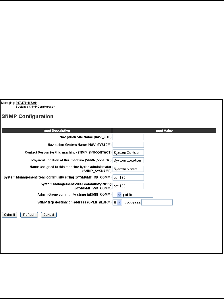
Page 378 of 910 Configuration of IP Telephony nodes using Element Manager
553-3001-365 Standard 4.00 August 2005
Note: If the community name strings are forgotten, connect a TTY to the
Voice Gateway Media Card maintenance port. Restart the card. The card
displays the community name on the TTY during start-up.
To configure the community name strings in Element Manager, follow the
steps in Procedure 28.
Procedure 28
Configuring the community name strings
1Select System > SNMP. See Figure 87.
Figure 87
System > SNMP Configuration window

Configuration of IP Telephony nodes using Element Manager Page 379 of 910
IP Line Description, Installation and Maintenance
2Obtain the following information from the system administrator and enter
it in the appropriate fields:
• Navigation Site Name (NAV_SITE)
• Navigation System Name (NAV_SYSTEM)
• Contact person for this machine (SNMP_SYSCONTACT)
• Name assigned to this machine by the administrator
(SNMP_SYSNAME)
• System Management Read community string
(SYSMGMT_RD_COMM)
• System Management Write community string
(SYSMGMT_WR_COMM)
• Admin Group community string (ADMIN_COMM).
Select 1, 2, or 3 from the drop-down list.
• SNMP trap destination address (OPEN_ALARM)
3Click Submit to save the configuration or Cancel to cancel the entry.
Note: Click Refresh to retrieve the current information from the system.
End of Procedure
Synchronization of community name strings
After the system community name strings are configured, it is necessary to
perform a data dump to synchronize these community name strings from the
Call Server to the Signaling Server and Voice Gateway Media Cards. As well,
when a link is established between the Signaling Server or Voice Gateway
Media Cards and the Call Server, the Call Server transmits the community
name strings to those devices.
Configure Voice Gateway Profile data
Follow the steps in Procedure 29 on page 380 to configure the Voice Gateway
Profile data.
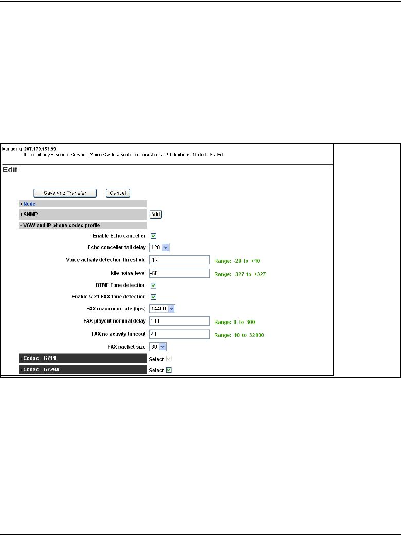
Page 380 of 910 Configuration of IP Telephony nodes using Element Manager
553-3001-365 Standard 4.00 August 2005
Procedure 29
Configuring DSP Profile data
1In the Edit window, click VGW and IP Phone codec profile.
The VGW and IP phone codec profile information expands. See Figure
88.
The VGW and IP phone codec profile area includes VGW information
and a list of codecs.
Figure 88
Node Configuration > Edit > VGW Profile
2Under VGW and IP phone codec profile, leave the values at their default
settings unless directed to change them by Nortel Field Support.
a. Enable Echo canceller: The echo canceller is enabled by default.
Do not uncheck this box. Never disable echo canceller unless
directed by Nortel Field Support.
b. Echo canceller tail delay: Select the maximum value available. The
default value is 128ms. Never reduce the echo canceller value unless
directed by Nortel Field Support.

Configuration of IP Telephony nodes using Element Manager Page 381 of 910
IP Line Description, Installation and Maintenance
c. Voice activity detection threshold: The default value is –17db. The
range is –20db to +10db.
d. Idle noise level: The default value is –65db. The range is –327db to
+327db.
e. DTMF Tone detection: Ensure this is checked to enable DTMF tone
detection. This is enabled by default.
f. Enable V.21 FAX tone detection: Ensure this is checked to enable
V.21 FAX tone detection. This is enabled by default.
g. FAX maximum rate: The FAX maximum rate is one of the following
values: 2400, 4800, 7200, 9600, 12000, or 14400. The default value
is 14400 bps.
h. FAX playout nominal delay: The default value is 100 ms. The range
is 0ms to 300ms.
i. FAX no activity timeout: The default value is 20 seconds. The
range is 10 seconds to 32000 seconds.
j. FAX packet size: Select the desired FAX packet size. The default
value is 30 bytes. The range is 20 to 48 bytes.
To select a codec, scroll through the list, and click the corresponding
Select check box. See Figure 89 on page 382 for codec samples. A
maximum of four codecs can be selected.
Recommendation
Nortel recommends that the system be configured with both G.711 and
G.729A if there is a possibility that an IP Softphone 2050 could be
configured with the “I use a modem to connect to the network” check box
checked. If the node does not have G.729A and/or G.723 configured, IP
Softphone 2050 users with that checkbox selected will have calls
blocked.
(Note: This does not apply to the MVC 2050 as it only supports G.711
capability; there is no dial-up capability.)
For more information, refer to IP Phones: Description, Installation, and
Operation (553-3001-368) in the “Select Sound Devices tab” section.
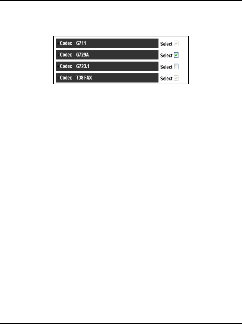
Page 382 of 910 Configuration of IP Telephony nodes using Element Manager
553-3001-365 Standard 4.00 August 2005
Figure 89
Codec list
Note: The codec list contains four codec settings for G.711, G.729A,
C.723.1, and T.38 FAX for the Voice Gateway Media Card.
3The G.711, G711 Clear Channel, and T.38 FAX codecs are selected by
default, and these selections cannot be cleared. However, the following
changes can be made:
• The payload size, jitter buffer setting, and companding law for the
G.711 codec can be changed. The default is G.711 mu-law.
• Only the jitter buffer can be changed for the G.711 Clear Channel
codec.
Up to three additional codecs can be optionally selected: G.729A,
G.729AB, and/or G.723.1 codecs.
• If the G.729A or G.729AB codec are selected, the payload and jitter
buffer can be changed. The payload defaults are the maximum
supported payload.
• If the G.723.1 codec is selected, only the jitter buffer can be changed.
The payload size of 30 msec is the only supported payload.
Note: The supported G.723.1 codec has bit rates of 5.3 Kbps and
6.3 Kbps.
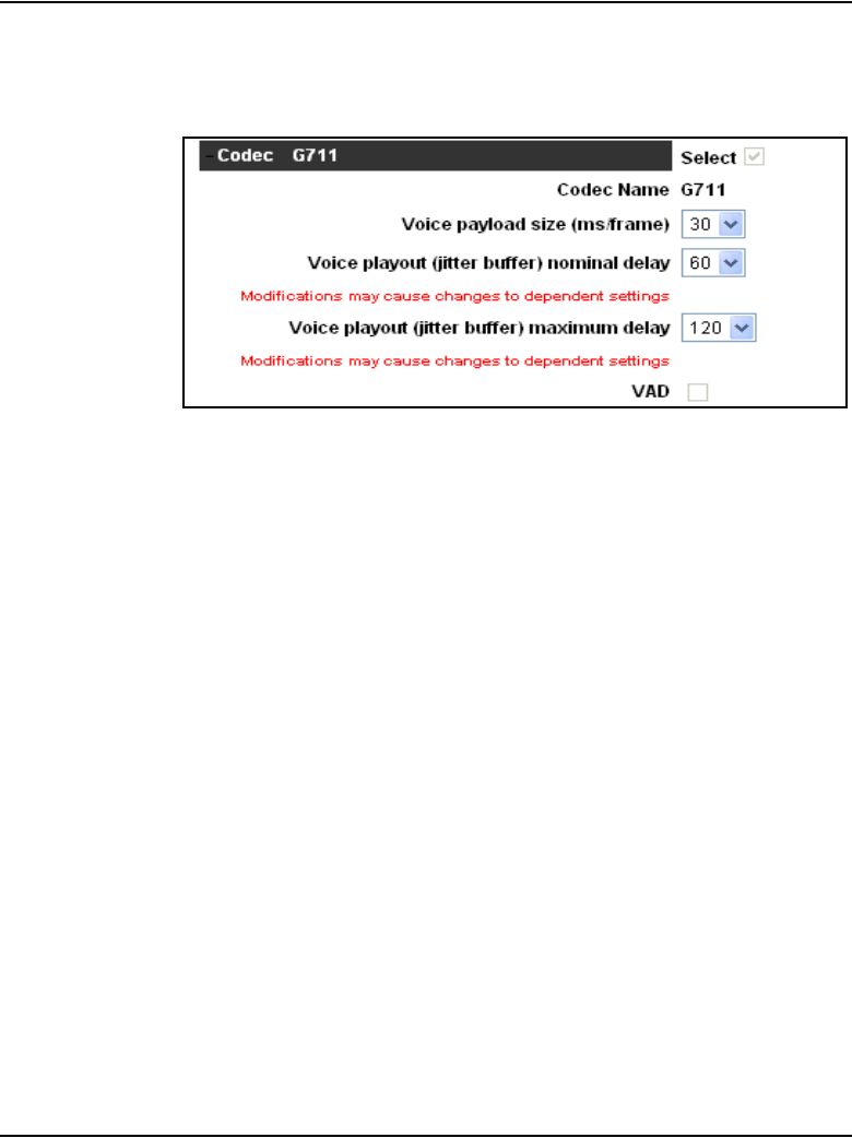
Configuration of IP Telephony nodes using Element Manager Page 383 of 910
IP Line Description, Installation and Maintenance
4Expand the selected Codec. See Figure 90.
Figure 90
Selected Codec
Element Manager enables some jitter buffer adjustments on the browser
side. The following are the jitter buffer adjustments that are made in
Element Manager:
• A change of payload resets the Nominal Voice Playout (NVP) and
Maximum Voice Playout (MVP) values to the default recommended
values:
NVP = 2 * payload
MVP = NVP + 2 * payload
• A change of NVP value changes the MVP value to the default
(MVP = NVP + 2 * payload) and changes the values listed in the MVP
pull down list so the minimum value listed does not violate the
requirement of NVP + 2 * payload.
• The MVP value can be changed. The pull-down values range from
the minimum recommended value (see above) to the maximum
allowed value for the selected codec type.

Page 384 of 910 Configuration of IP Telephony nodes using Element Manager
553-3001-365 Standard 4.00 August 2005
5Configure the following values for the codec:
a. Codec Name: The codec name is based on the selected codec.
b. Voice payload size (msecs/frame): The payload size is determined
by the selected codec.
For each codec type, the payload is defaulted to the maximum
supported: 30 msec for G.711 (a-law and mu-law), 50 msec for
G.729A, 50 msec for G.729AB, and 30 msec for the G.723.1.
Note: If a system has multiple nodes and the same codec is selected on
more than one node, ensure that each node has the same voice payload
size configured for the codec.
c. Voice playout (jitter buffer) nominal delay: Set the nominal value
to the highest setting that the device allows. The range is 20–200 ms
and is dependent on the codec. Changing this value can cause the
automatic adjustment of the other settings for this codec. For more
information, see Converging the Data Network with VoIP
(553-3001-160).”
d. Voice playout (jitter buffer) maximum delay: The maximum delay
has a range of 60–500 ms and is dependent on the codec. Changing
this value can cause the automatic adjustment of the other settings
for this codec.
e. VAD: Select this check box to enable Voice Activity Detection.
6Repeat step 5 for each of the selected codecs.
End of Procedure
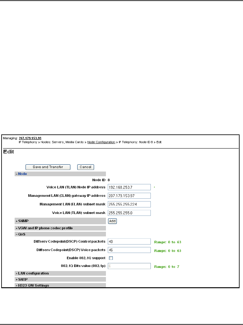
Configuration of IP Telephony nodes using Element Manager Page 385 of 910
IP Line Description, Installation and Maintenance
Configure Quality of Service
The Quality of Service (QoS) section includes the settings for the following:
• DiffServ CodePoint (DSCP)
• 802.1Q support
Follow the steps in Procedure 30 to configure QoS.
Procedure 30
Configuring QoS
1In the Edit window, click the plus sign (+) to the left of QoS.
See Figure 91.
Figure 91
Configuration > IP Telephony > Node Summary > Edit > Qos

Page 386 of 910 Configuration of IP Telephony nodes using Element Manager
553-3001-365 Standard 4.00 August 2005
2The Differentiated Service (DiffServ) CodePoint (DSCP) value
determines the priorities of the management and voice packets in the IP
Line network. The range for both management and voice packet DiffServ
is 0 – 63 inclusive.
The DiffServ value can be configured, if required, to obtain better QoS
over the IP data network (LAN/WAN).
The value entered depends on the policy in the customer’s data network.
Note: Do not change DiffServ from the default values unless instructed
by the IP network administrator.
Only modify the Control packets priority and Voice packets priority values
as and when directed by the IP network administrator.
The recommended configuration values are as follows:
a. Diffserv CodePoint (DSCP) Control packets: A value of 40 - Class
Selector 5 (CS5). The range is 0 – 63. This configures the priority of
the signaling messaging.
b. Diffserv CodePoint (DSCP) Voice packets: A value of 46 Control
DSCP - Expedited Forwarding (EF). The range is 0 – 63.
3802.1Q enables Virtual LANs (VLANs) to be defined within a single LAN.
This improves bandwidth management and limits the impact of broadcast
storms and multicast messages.
a. Enable 802.1Q support: 802.1Q support is disabled by default.
b. 802.1Q Bits value (802.1p): The priority field is a 3-bit value, with a
default value of 6. The range is 0 – 7. A value of 6 is recommended
by Nortel. The p bits within the 802.1Q standard enables packet
prioritization at Layer 2, improving network throughput for IP
Telephony data.
End of Procedure
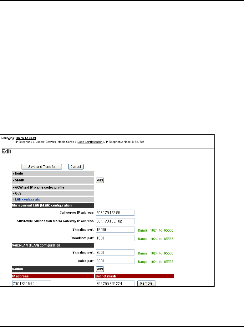
Configuration of IP Telephony nodes using Element Manager Page 387 of 910
IP Line Description, Installation and Maintenance
Configure ELAN IP address (Active ELNK), TLAN voice
port, and routes (Small Systems and CS 1000S only)
The LAN configuration section is used for configuring the Call Server ELAN
IP address (Active ELNK), TLAN voice port, and routes.
This information is applicable only to Small Systems and CS 1000S systems.
Procedure 31
Configuring the Call Server ELAN network interface IP address (Active
ELNK), TLAN voice port, and routes on a Small System
1Click LAN Configuration.
See Figure 92.
Figure 92
Node Configuration > Edit > LAN configuration

Page 388 of 910 Configuration of IP Telephony nodes using Element Manager
553-3001-365 Standard 4.00 August 2005
2Enter the following Management LAN (ELAN) configuration settings:
a. Call Server IP address: This is the IP address of the Call Server on
the ELAN subnet. Enter the Call Server ELAN network interface
IP address (Active ELNK).
Note: The Call Server ELAN network interface IP address must
correspond to the Active ELNK IP address configured in LD 117. The IP
address must be in the same subnet as the ELAN subnet for the IP Line
node.
b. Survivable Media Gateway IP address: This address is configured
for survivability. It is the IP address of the Survivable CS 1000S
Media Gateway on the ELAN subnet.
Note 1: The Survivable CS 1000S Media Gateway IP address must
correspond to the Active ELNK IP address. If configured, all Voice
Gateway Media Cards in the same node should be in the same Survivable
Cabinet.
Note 2: The Survivable Media Gateway associated with the Primary
Signaling Server IP Telephony node is called the Alternate Call Server. It
is normally located in the same equipment rack with the Call Server and
Signaling Server; therefore, it is normally connected to the same ELAN
subnet as the Call Server and the Primary Signaling Server IP Telephony
node. The Alternate Call Server Media Gateway should be equipped with
sufficient trunk cards, Voice Gateway Media Cards, and centralized
CallPilot, so that it provides a large degree of survivability in case of
Call Server equipment failure for IP Phone users who normally register
through the Signaling Server.
Refer to Communication Server 1000S: Planning and Engineering
(553-3031-120) and Communication Server 1000S: Installation and
Configuration (553-3031-210) for more information about survivability.
c. Signaling port: The default value is 15000. The range is 1024 to
65535.
d. Broadcast port: The default value is 15001. The range is 1024 to
65535.

Configuration of IP Telephony nodes using Element Manager Page 389 of 910
IP Line Description, Installation and Maintenance
3Under Voice LAN (TLAN) configuration:
a. Signaling port: The default value is 5000. The range is 1024 to
65535. The TLAN Signaling occurs on UDP ports 7300, 4100, 5100,
and 5000.
b. Voice port: Change the Voice port only as instructed by the IP
network administrator to improve QoS for the IP Phones. For
example, if RTP Header compression is used to reduce voice
bandwidth on narrow band WAN links, then the TLAN voice port
range needs to be set to 16384 or higher. The exact range is
provided by the system administrator. The TLAN Voice port range is
1024 to 65535. The default Voice ports are 5200 – 5295.
4Click the Add button to the right of Routes if entries must be made to the
card routing table. The Routes information expands.
See Figure 93 on page 390.
CAUTION
Do not set the Voice port to a value that is already used
for signaling (4100, 5000, 5100, 7300).
The Voice port defines the first port in a range spanning
the gateway channels on the card; this means a Voice
port value of 5200 reserves the following:
• ports 5200 – 5263 on the Media Card 32-port line
card
• ports 5200 – 5215 on the Media Card 8-port line card
• and 5200 – 5247 on the ITG-P 24-port line card.
If this value is changed from the default, verify that the
selected Voice port value does not intrude into one of the
reserved Signaling port values.
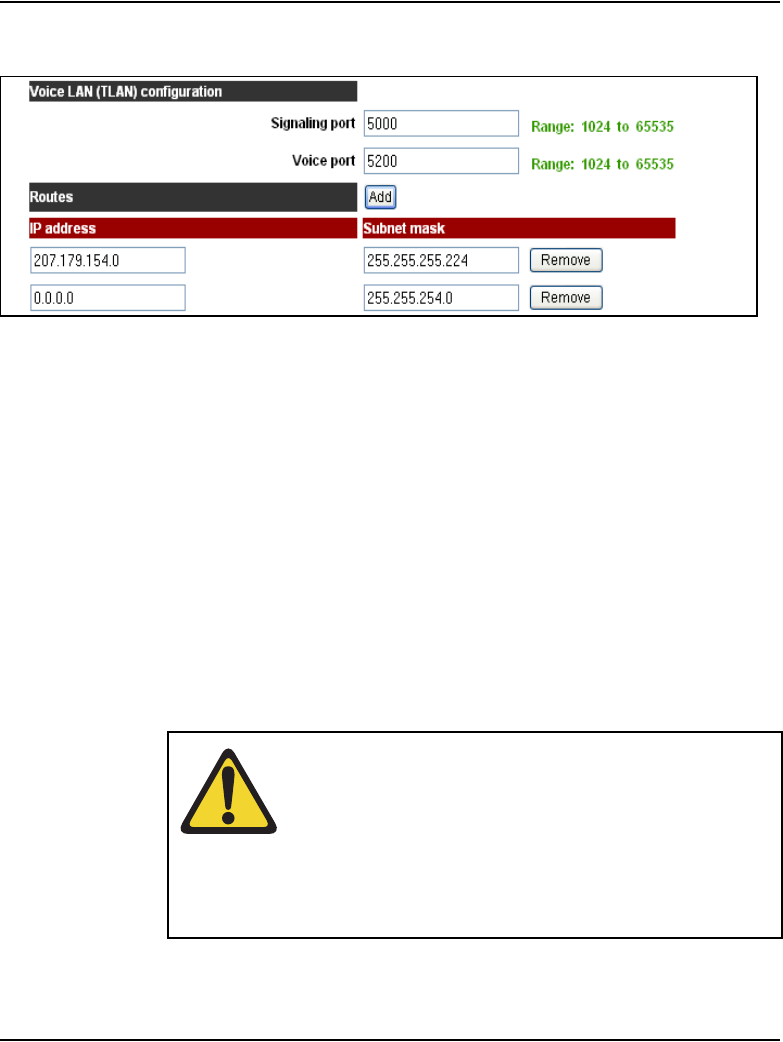
Page 390 of 910 Configuration of IP Telephony nodes using Element Manager
553-3001-365 Standard 4.00 August 2005
Figure 93
Routes
Under Routes, enter the IP address and Subnet mask for any host that
is not on the ELAN subnet but requires access to the Voice Gateway
Media Card across the ELAN subnet. A Telnet session for maintenance
from a remote PC is an example of when this would be needed. The
address of the remote PC would be added in the Route list.
The default route on the card causes packets destined for unknown
subnets to be sent out on the TLAN network interface. Packets from an
external host arrive on the ELAN network interface and responses are
sent on the TLAN network interface. This process can cause one-way
communication if the TLAN subnet is not routed to the ELAN subnet. It is
necessary to add an entry in the Route list to correct the routing so that
response packets are sent on the ELAN subnet. Each entry creates a
route entry in the card's route table that directs packets out the ELAN
network interface. See Figure 94 on page 391.
CAUTION
Use caution when assigning card routing table entries.
Do not include the IP address of an IP Phone. Otherwise,
voice traffic to these IP Phones is incorrectly routed
through the ELAN subnet and ELAN subnet gateway. To
avoid including the wrong IP address, Nortel
recommends that Host IDs are defined for the card
routing table entries.
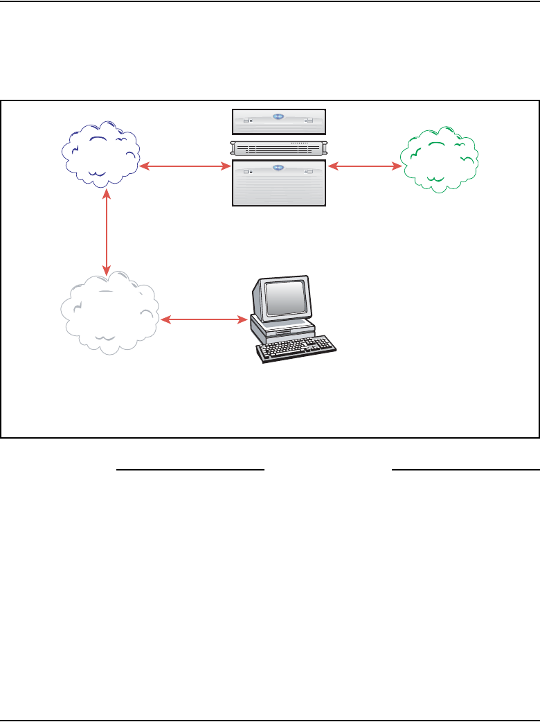
Configuration of IP Telephony nodes using Element Manager Page 391 of 910
IP Line Description, Installation and Maintenance
5To add additional routes, click the Add button again and enter the route
information. Repeat this step for each route to be added.
Figure 94
Specifying additional ELAN routes
End of Procedure
In this diagram, an additional ELAN route is required to
reach the management workstation, which is accessible
throu
g
h the ELAN network interface but is not on the ELAN subnet.
Management
Workstation
Meridian 1 or CS 1000
TLAN route /
default route
ELAN route +
additional routes
ELAN
subnet TLAN
subnet
Some
other
LAN

Page 392 of 910 Configuration of IP Telephony nodes using Element Manager
553-3001-365 Standard 4.00 August 2005
Configure file server access
With the addition of more IP Phones, there are also additional firmware files
for the IP Phones. The Voice Gateway Media Card has limited space to store
the files on the card for all the telephones. As a result, a UFTP server is used
to store the telephone firmware files. For more information, see “IP Phone
firmware” on page 240
The IP Phone firmware files are labeled as follows:
• 0603Bnn.BIN is the filename for the Phase I IP Phone 2002 firmware
where Bnn = F/W version 1.nn.
• 0602Bnn.BIN is the filename for the Phase I IP Phone 2004 firmware
where Bnn = F/W version 1.nn.
• 0603Dnn.BIN is the filename for the Phase II IP Phones firmware where
Dnn = F/W version 3.nn
If the external file server option is used in Element Manager for firmware
distribution with a node, the files must be renamed before being placed on the
server:
• 0602Bnn.BIN must be renamed to X00.fw
• 0603Bnn.BIN must be renamed to X01.fw
• 0604Dnn. BIN must be renamed to X02.fw
To configure the file server, follow the steps in Procedure 32 on page 393.
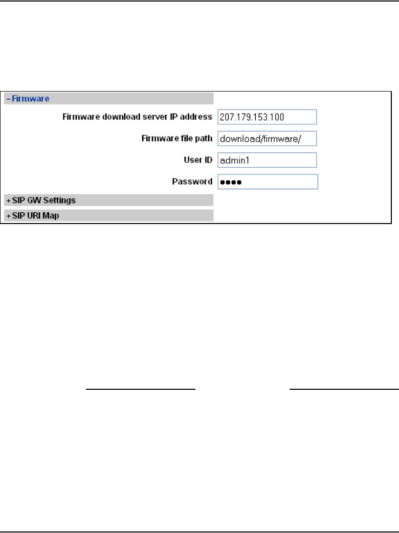
Configuration of IP Telephony nodes using Element Manager Page 393 of 910
IP Line Description, Installation and Maintenance
Procedure 32
Configuring access to the file server
1Click Firmware. See Figure 95.
Figure 95
Configuration > Node Summary > Edit > Firmware
2Specify the parameters needed to connect to the file server:
a. Firmware download server IP address: Enter the IP address of the
file server where the firmware will be downloaded.
b. Firmware file path: Enter the path for the location of the firmware
files. See page 243 for the default location of firmware files for the
CS 1000 system.
c. User ID: Enter the User ID that is required to access the file server.
d. Password: Enter the Password that is required to access the file
server.
End of Procedure

Page 394 of 910 Configuration of IP Telephony nodes using Element Manager
553-3001-365 Standard 4.00 August 2005
Configure loss and level plan
The loss and level plan determines parameters, such as transmission gain, that
vary from country to country.
Dynamic Loss Plan
A Dynamic Loss Plan has been implemented to define the gateway loss value
per endpoint connection type. The loss plan adjusts the Voice Gateway Media
Card gateway channel's loss for each call by sending pad values to the card.
Loss plan values are now configured through LD 73.
Default values
The default values in the system are for the North American loss plan.
Non-North American countries
Installation of IP Line 4.5 in any other country requires setting the pad values
in Table 15 to that country's loss plan. If the system is installed in other
countries, the GPRI package (International 1.5/2.0 Mb/s Gateway
package 167) must be used, and the NTP-specified values must be entered in
LD 73. At the PDCA prompt, enter Table 15.
Refer to Transmission Parameters (553-3001-182) for more information.
United Kingdom
In addition, when a system is installed in the UK, the CLI command
UKLossPlanSet is entered at the CLI of one card in each node. This adjusts
the loss plan of the IP Phones to the higher transmit levels required in the UK.
Follow the steps in Procedure 33 to set the loss plan for the UK.
Procedure 33
Setting the loss plan for the UK
1Telnet to the card, connect to the maintenance port, or use OTM 2.2 or
Element Manager to access the Voice Gateway Media Card.
2Log into the IPL> shell.
3At the IPL > CLI, enter the command UKLossPlanSet.
4Press <CR>.
Configuration of IP Telephony nodes using Element Manager Page 395 of 910
IP Line Description, Installation and Maintenance
5Exit from the login session.
End of Procedure
After the UKLossPlanSet command is entered, the loss plan adjustment is
transmitted by that card to all other cards in the node. The loss plan is then
adjusted on any registered IP Phones, and on other IP Phones as they register.
To clear the loss plan adjustment, use the command UKLossPlanClr.
Refer to “IP Phone Loss Plan (UK) commands” on page 740 for more
information on these and other loss plan commands.
Add card and configure the card properties of the
Voice Gateway Media Card
If the network administrator provides IP addresses and subnet masks in CIDR
format, for example, “10.1.1.10/24”, convert the subnet mask to dotted
decimal format. See Appendix E on page 901.
Note: In the Cards section, cards can be added, changed, or removed in
the node one at a time.
Follow the steps in Procedure 34 to add a new Voice Gateway Media Card
and configure its properties, or to configure the properties of an existing
Voice Gateway Media Card.
Procedure 34
Adding card and configuring Voice Gateway Media Card properties
1Click Cards and then click the Add button.
See Figure 96 on page 396.
WARNING
Every node must has a Leader. Exercise caution when
removing the Leader card. If the Leader card is deleted,
a new Leader must be configured immediately.

Page 396 of 910 Configuration of IP Telephony nodes using Element Manager
553-3001-365 Standard 4.00 August 2005
Figure 96
IP Telephony > Nodes: Servers, Media Cards > Edit > Cards
2Enter the Card Properties data for Leader 0 and Follower cards. The
fields with asterisks are required fields:
a. Role: The role is assigned based on the information that Element
Manager reads from the card configuration. This is a read-only field.
b. Management LAN (ELAN) IP address: This is the ELAN network
interface IP address for the card. Element Manager and the system
use this IP address to communicate with the card.
c. Management LAN (ELAN) MAC address: This is the motherboard
Ethernet address from the “Voice Gateway Media Card installation
summary sheet” on page 307.
d. Voice LAN (TLAN) IP address: This is the TLAN network interface
IP address for the card.
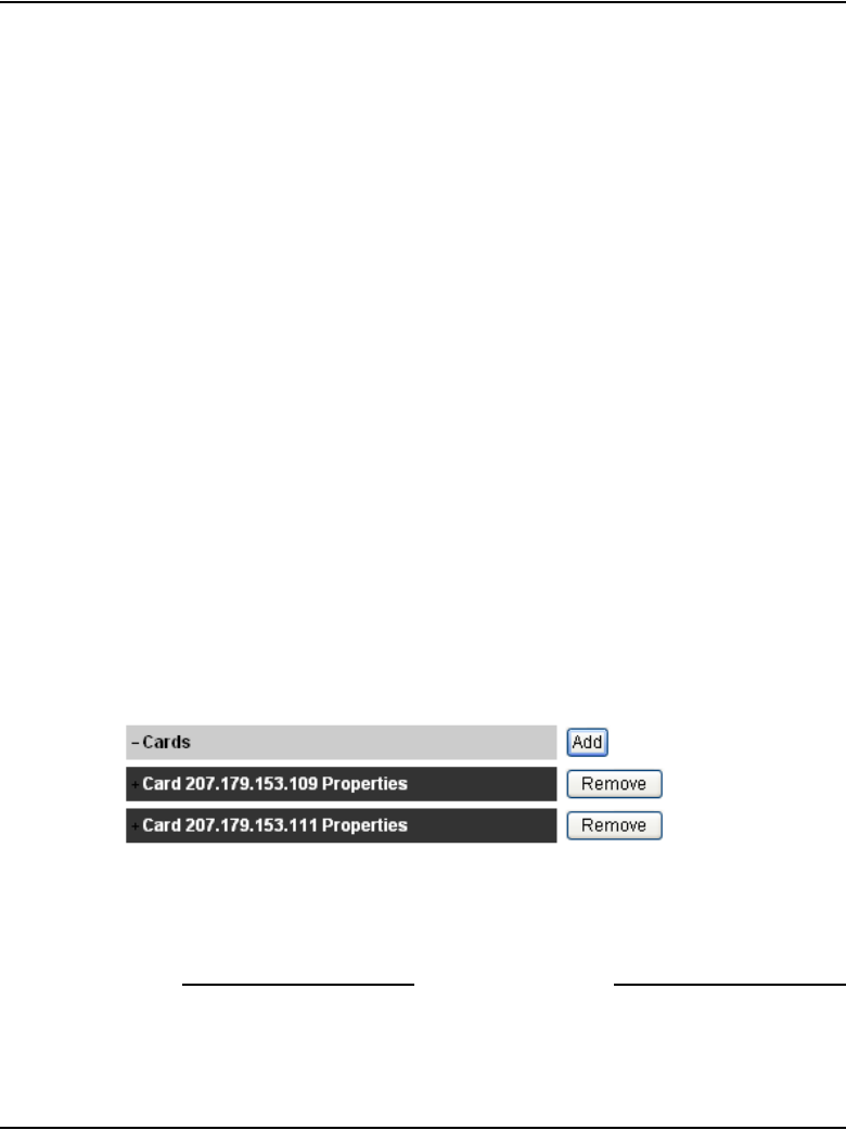
Configuration of IP Telephony nodes using Element Manager Page 397 of 910
IP Line Description, Installation and Maintenance
e. Voice LAN (TLAN) gateway IP address: This is the IP address of
the router interface on the TLAN subnet.
f. Hostname: This is the Host name.
g. Card TN: Enter the card slot number between 1 – 50.
h. Card processor type: Choose either Pentium or Media Card from
the drop-down list. Select Pentium if using the ITG-P 24-port line card
(dual-slot card). Select Media Card if using the Media Card 32-port or
8-port line card (single-slot card).
i. H323 ID: The H323 ID within IP Line 4.5 is for the Virtual Office/
Media Gateway 1000B feature. Keep the H323 ID the same for all the
elements within one node.
j. Enable set TPS: Select the check box.
k. System name: Enter the name of the system.
l. System location: Enter the location where the system resides.
m. System contact: Enter a contact name and telephone number.
3To add additional cards to the node, click the Add button again and enter
the new card information. Repeat this step for each card that is being
added to the node.
New cards appear under the Cards menu as they are added. See
Figure 97.
Figure 97
Cards added to the system
4To edit the properties of an existing Voice Gateway Media Card, click the
plus sign (+) to the left of the card to be edited to display the card’s
properties and make the desired changes.
End of Procedure

Page 398 of 910 Configuration of IP Telephony nodes using Element Manager
553-3001-365 Standard 4.00 August 2005
Submit and transfer the node information
To submit node changes and transfer the changes to the Call Server, follow
the steps in Procedure 35.
Procedure 35
Submitting and transferring the node information
1Click Save and Transfer when all the node information is configured in
the Edit window.
Clicking Save and Transfer saves and transfers the data to the Call
Server.
Note: There is a Save and Transfer button at both the top and bottom
of the Edit window.
The Edit window closes, and the Node Configuration window opens
with the new node added.
Note 1: Save and Transfer can be clicked after each section is
configured in the Edit window. However, each time Save and Transfer is
clicked, the Edit window closes and the Node Configuration window is
displayed. To continue the node configuration, click the Edit button to
return to the Edit window.
Note 2: If Cancel is clicked, all information that has been configured is
discarded. The Edit window closes and the Node Configuration window
opens.
2Click the Transfer/Status button for the node.
The Transfer confirmation dialog box opens.
3Click OK to confirm the transfer. See Figure 98.
Figure 98
Transfer confirmation dialog box

Configuration of IP Telephony nodes using Element Manager Page 399 of 910
IP Line Description, Installation and Maintenance
After a few seconds, the Transfer Progress window opens and displays
each of the Voice Gateway Media Cards in the node. See Figure 99 on
page 400.
The Voice Gateway Media Cards retrieve the CONFIG.INI and
BOOTP.TAB files from the Call Server. A check mark is added to each
field as the card receives its CONFIG.INI and BOOTP.TAB files.
4When the transfer is complete, click OK in the Transfer Successful
dialog box. See Figure 100 on page 400.
• If the transfer is successful for a card, the Status column displays
“Complete” and a check mark is displayed.
• If the transfer is unsuccessful, the Status column displays “Fail”.
A failed transfer can be caused by several situations, including the
following:
— improper cabling. Check cable connections.
— improper card configuration. Ensure all information is configured
correctly.
— the Voice Gateway Media Card running an older version of the
software than the Signaling Server. Verify the software version
on the Voice Gateway Media Card and upgrade the software if
necessary. Refer to “Upgrade the Voice Gateway Media Card
software and IP Phone firmware” on page 415.
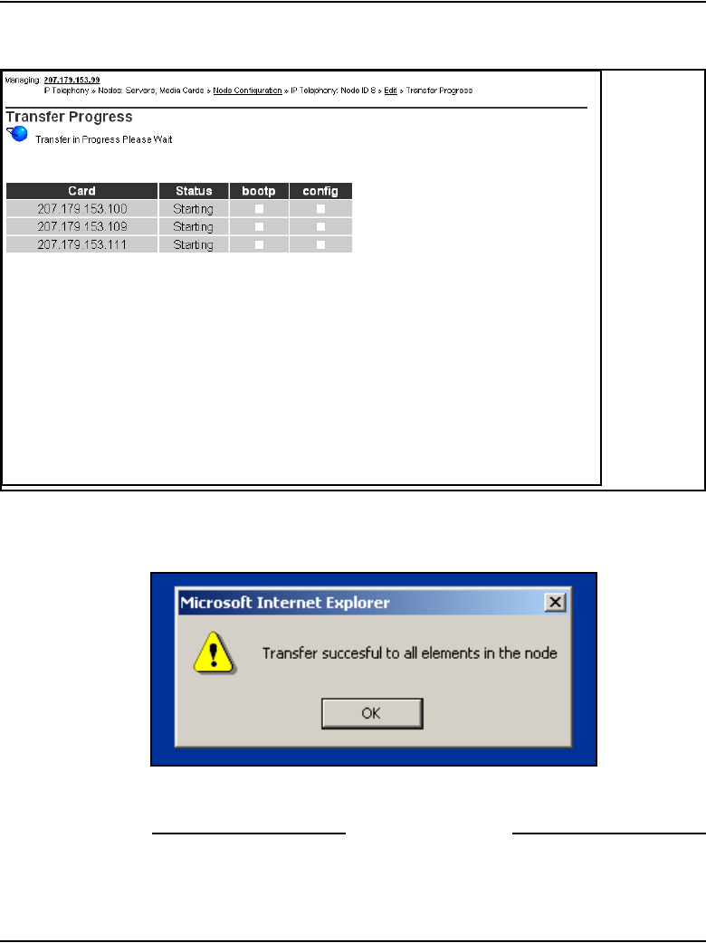
Page 400 of 910 Configuration of IP Telephony nodes using Element Manager
553-3001-365 Standard 4.00 August 2005
Figure 99
Transfer Progress window
Figure 100
Transfer Successful message box
End of Procedure

Configuration of IP Telephony nodes using Element Manager Page 401 of 910
IP Line Description, Installation and Maintenance
Transfer node configuration from Element Manager
to the Voice Gateway Media Cards
Before beginning the node configuration transfer, ensure the following:
• The Voice Gateway Media Cards and cables have been installed.
• The ELAN and TLAN network interfaces of all cards have access to the
IP network.
• To enable access to Element Manager through a web browser, a network
PC must be able to access the node’s Signaling Server, either directly or
remotely.
The IP Telephony node and card properties are configured using Element
Manager. The configuration data is saved to the Call Server and then
transferred to the Voice Gateway Media Cards.
Saving the configuration
The configuration data is saved when the Save and Transfer button in the
Edit window is clicked. The files are saved to the Call Server. After the data
is saved, the configuration must be transferred to the Voice Gateway Media
Card. When Transfer/Status in the Edit window is clicked, Element
Manager instructs each card where to retrieve the files using FTP. The Voice
Gateway Media Card then retrieves the CONFIG.INI and BOOTP.TAB files.
Transferring the configuration - main node
For a Signaling Server node, the process to transfer the node configuration to
the cards consists of the following steps:
1Transmit the node properties. See Procedure 37 on page 405.
2Configure the Follower card. See Procedure 38 on page 411.
Note: The following sequence of steps are applicable only to nodes that
do not use the Signaling Server as the Leader card; that is, a second (or
subsequent) node is being configured on the system – not the main node.
The Signaling Server must be properly configured to use Element
Manager, so that the steps of setting and rebooting the Leader are not
needed. The Signaling Server requires a reboot only if the Signaling
Server IP address information has been changed, such as the node IP

Page 402 of 910 Configuration of IP Telephony nodes using Element Manager
553-3001-365 Standard 4.00 August 2005
address or Signaling Server TLAN network interface IP address. The
Voice Gateway Media Cards require a reboot only if the card network
interface IP address information has changed.
Transferring the configuration - second node
For a second (or subsequent) node, the process to transfer the node
configuration to the cards consists of the following steps:
1Configure the Leader IP address. See Procedure 36 on page 402.
2Transmit the node properties. Procedure 37 on page 405.
3Configure the Follower card. See Procedure 38 on page 411.
Configuring the Leader network interface IP address
Follow the steps in Procedure 36 on page 402 to configure the network
interface IP address of the Leader Voice Gateway Media Card.
Procedure 36
Configuring the Leader IP address for a second or subsequent node
1Access the IPL> CLI by connecting the COM port of a PC to the RS-232
serial maintenance port on the faceplate of the Leader Voice Gateway
Media Card with an NTAG81CA PC Maintenance cable.
If required, use an NTAG81BA Maintenance Extender cable between the
PC Maintenance cable and the PC.
Alternatively, connect the NTAG81BA Maintenance Extender cable to the
female DB-9 connector of the NTMF94EA ELAN, TLAN RS-232 Ports
cable for a more permanent connection to the Voice Gateway Media Card
serial maintenance port.
Note: Never connect two terminals to the faceplate and I/O panel
breakout cable serial maintenance port connectors at the same time.
2Use the following communication parameters for the TTY terminal
emulation on the PC:
• 9600 baud
• 8 bits
• no parity
• one stop bit

Configuration of IP Telephony nodes using Element Manager Page 403 of 910
IP Line Description, Installation and Maintenance
3Observe the Leader card faceplate maintenance display window.
When the display reads “T:20”, the card begins to send BootP requests
on the ELAN subnet. A series of dots is printed on the TTY.
4Type +++ to escape from the BootP request.
5At the Login prompt, enter the user ID and password to access the
IPL> CLI:
• If the card is a new card (out of the box), then the user ID is itgadmin
and the password is itgadmin.
• If the card has been previously connected to the Call Server, then the
user ID and password are the PWD1 of the Call Server.
• If the user ID and password are forgotten, see Procedure 71 on
page 558 to reset the IPL> CLI Shell username and password.
6When the maintenance window displays “T:21”, log into the IPL> CLI.
At the IPL> prompt, enter the setLeader command to configure the
Leader Management LAN (ELAN) network interface IP address,
Management LAN gateway IP address and the Management LAN subnet
mask:
setLeader “xx.xx.xx.xx”,“yy.yy.yy.yy”,“zz.zz.zz.zz”
Note 1: The three parameters must each be enclosed in double
quotation marks. There must be a space after the command and before
the first parameter. Put commas and no spaces between the following
parameters:
“xx.xx.xx.xx” = IP address.
Enter the same IP address that was entered in the Management LAN
IP address field for Leader in the Cards menu of the Edit window.
“yy.yy.yy.yy” = Gateway IP address.
Enter the same IP address that was entered in the Management LAN
gateway IP address field in the Node menu of the Edit window. If
there is none, enter the following: “0.0.0.0”
“zz.zz.zz.zz” = Management LAN subnet mask.
Enter the same address that was entered in the Management LAN
subnet mask field Node menu of the Edit window.
Note 2: This step assumes that the new IP Telephony node has already
been configured in Element Manager.
7Reboot the Leader Voice Gateway Media Card.
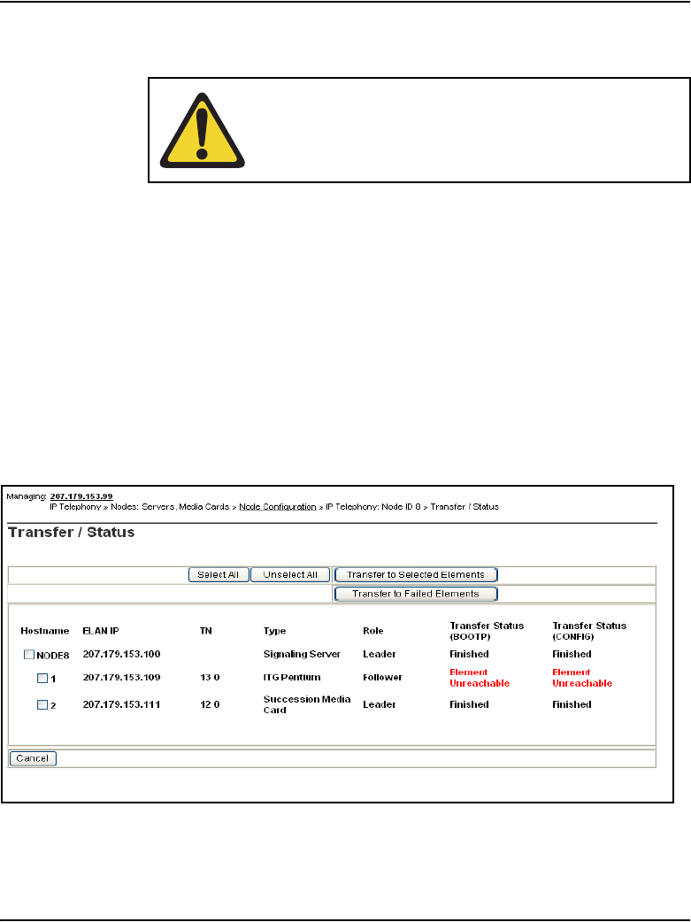
Page 404 of 910 Configuration of IP Telephony nodes using Element Manager
553-3001-365 Standard 4.00 August 2005
At the IPL> prompt, enter: cardReset, or press the Reset button on the
faceplate of the Leader Voice Gateway Media Card.
8Check the maintenance display for T:22 to confirm a successful reboot.
9Log into Element Manager.
10 In the Element Manager navigator, click > IP Telephony > Nodes:
Servers, Media Cards > Configuration.
The Node Configuration window opens.
11 Click Transfer/Status to check the status of the Voice Gateway Media
Card.
The Transfer/Status window is displayed. See Figure 101.
Figure 101
Transfer/Status window
WARNING
Do not use a pencil to reset the Voice Gateway Media
Card. The graphite carbon can create an electrical short
circuit on the board.
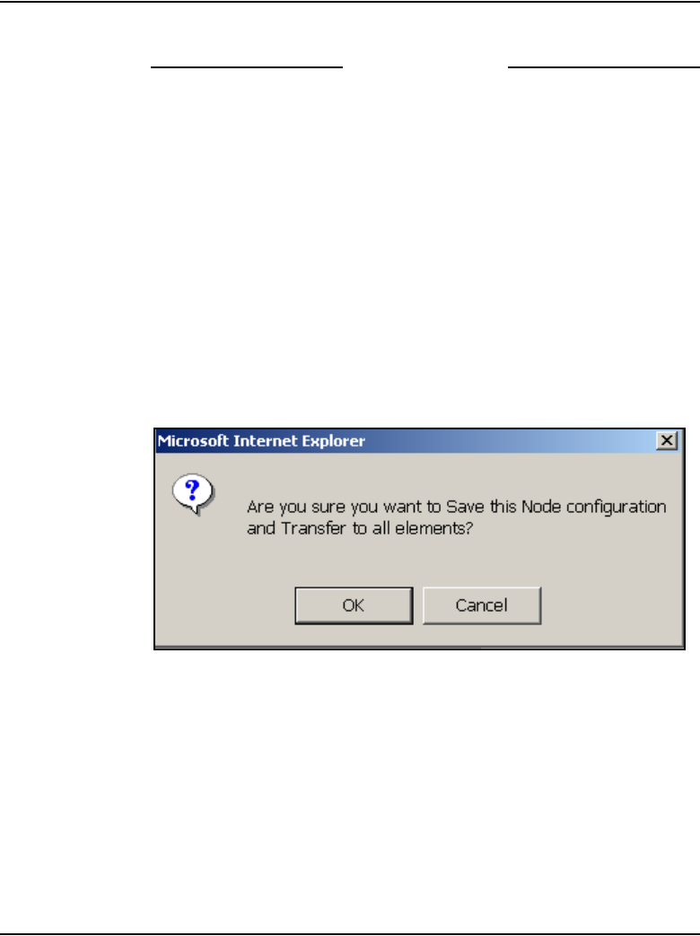
Configuration of IP Telephony nodes using Element Manager Page 405 of 910
IP Line Description, Installation and Maintenance
12 If the card role is not correct, verify LAN connections and IP configuration.
End of Procedure
Transmit node properties
To transmit the node properties to the Leader, follow the steps in
Procedure 37 on page 405.
Procedure 37
Transmitting node properties to Leader
1If changes are made to the node or card configuration data, ensure the
data is saved to the Call Server by clicking the Save and Transfer button
in the Edit window.
A confirmation dialog box opens. See Figure 102.
Figure 102
Confirm Submit
2Click OK to confirm the save of the node data.
The Edit window closes, and the Node Configuration window opens.
3In the Node Configuration window, click the Transfer/Status button
associated with the node.
The Transfer/Status window opens. See Figure 103 on page 406.
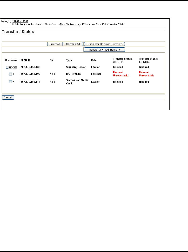
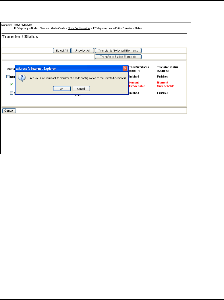
Configuration of IP Telephony nodes using Element Manager Page 407 of 910
IP Line Description, Installation and Maintenance
Figure 104
Transfer confirmation dialog box
6Click OK.
Element Manager notifies the Leader and the Voice Gateway Media
Cards, which then retrieve the CONFIG.INI and BOOTP.TAB files from
the Call Server.
The Transfer Progress window opens and displays each of the Voice
Gateway Media Cards in the node. See Figure 105.
The Voice Gateway Media Cards retrieve the CONFIG.INI and
BOOTP.TAB files from the Call Server.
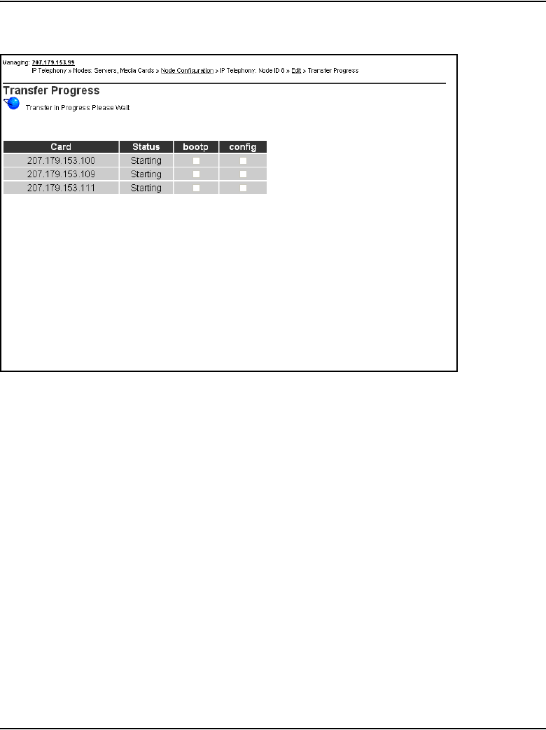
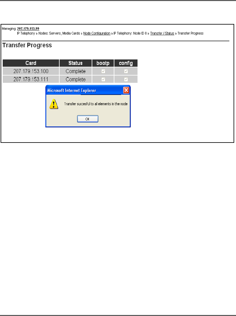
Configuration of IP Telephony nodes using Element Manager Page 409 of 910
IP Line Description, Installation and Maintenance
Figure 106
Transfer successful dialog box
If the transfer is successful for a card, the Status column displays
“Complete.” If the transfer is unsuccessful, the Status column displays
“Fail.”
8Reset the Leader card in the following situations:
• if the Leader card is a new card (out of the box)
• if the Leader card is a card that is being configured for the first time
as a Leader card
• if the Leader card’s IP address has changed
a. In the navigator, click IP Telephony > Maintenance and Reports.
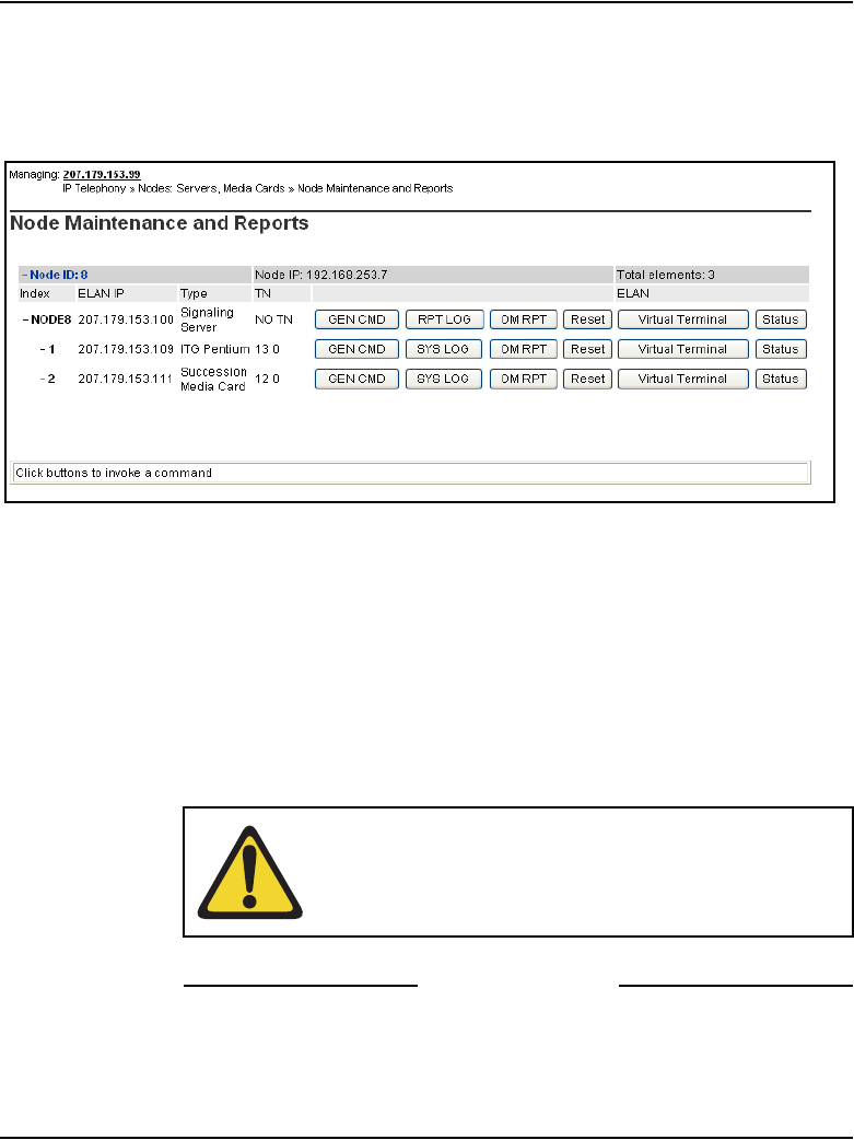
Page 410 of 910 Configuration of IP Telephony nodes using Element Manager
553-3001-365 Standard 4.00 August 2005
The Node Maintenance and Reports window opens. See
Figure 107.
Figure 107
Node Maintenance and Reports window
b. Expand the node by clicking the plus sign (+) to the left of the
associated node.
c. Click the Reset button for the Leader card.
Note 1: If any of the Signaling Server IP address information is changed,
the Signaling Server must be rebooted.
Note 2: Alternatively, restart the card by entering the cardReset
command at the IPL> prompt or by pushing the Reset button on the card’s
faceplate.
End of Procedure
WARNING
Do not use a pencil to reset the Voice Gateway Media
Card. The graphite carbon can create an electrical short
circuit on the board.

Configuration of IP Telephony nodes using Element Manager Page 411 of 910
IP Line Description, Installation and Maintenance
Configure the Follower cards
To configure a Follower card, follow the steps in Procedure 38.
Procedure 38
Configuring the Follower cards
1Check the displays on the card faceplate.
• After successfully rebooting, the Leader card is now fully configured
with the node properties of the node. The card enters a state of
“active Leader”. The card faceplate display shows Lxxx, where
xxx = the number of IP Phones registered with the LTPS on the
Leader card.
L000 shows that no IP Phones are registered.
• The Follower cards receive their BOOTP configuration information
from the Leader card. The Follower card faceplate display shows
Fxxx, where xxx = the number of IP Phones registered with the
Follower card’s LTPS.
F000 shows that no IP Phones are registered.
2Reboot the Follower card if the card’s faceplate does not display FXXX or
F000.
3Once all the Follower cards have the correct display on their faceplates,
log into Element Manager.
4Select IP Telephony > Nodes: Servers, Media Cards > Configuration.
The Node Configuration window opens.
5Click the Transfer/Status button associated with the node.
The Transfer/Status window opens. See Figure 108 on page 412.
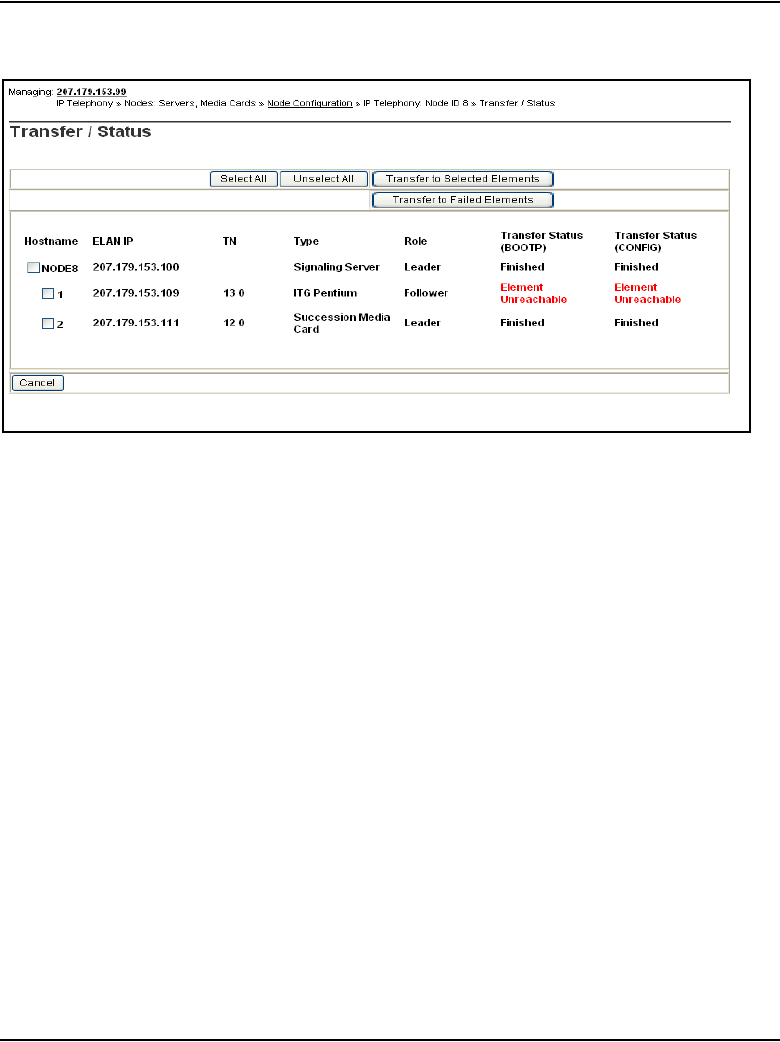
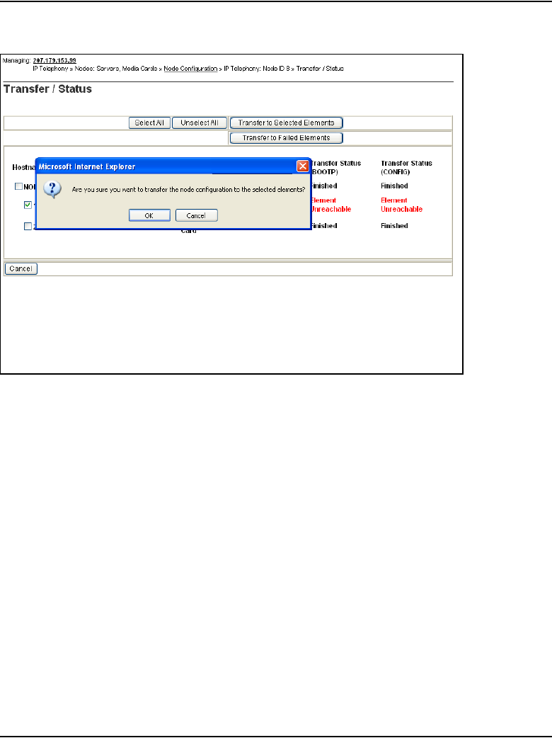
Configuration of IP Telephony nodes using Element Manager Page 413 of 910
IP Line Description, Installation and Maintenance
Figure 109
Transfer confirmation dialog box
The Transfer Progress window opens and displays each of the Voice
Gateway Media Cards in the node. The Voice Gateway Media Cards
retrieve the CONFIG.INI and BOOTP.TAB files from the Call Server.
9When the transfer is complete, click OK in the Transfer Successful
dialog box.
See Figure 110 on page 414.
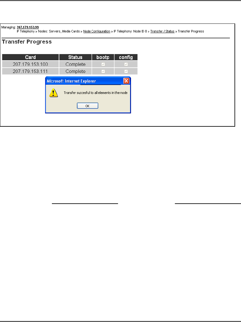
Page 414 of 910 Configuration of IP Telephony nodes using Element Manager
553-3001-365 Standard 4.00 August 2005
Figure 110
Transfer Successful message box
If the transfer is successful for a card, the Status column displays
“Complete.” If the transfer is unsuccessful, the Status column displays
“Fail.”
10 If the Follower card is a new card (never used before), then reboot the
card.
End of Procedure

Configuration of IP Telephony nodes using Element Manager Page 415 of 910
IP Line Description, Installation and Maintenance
Upgrade the Voice Gateway Media Card software and
IP Phone firmware
Before beginning, ensure that the following software is installed on the PC:
• Software to extract zipped files (WinZip or equivalent)
• Microsoft Internet Explorer version 6.02 (or later). NetScape Navigator
is not supported.
Upgrade procedure steps
The following steps are required to upgrade the Voice Gateway Media Card
loadware and IP Phone firmware:
1Determine the version of the software currently installed on the Voice
Gateway Media Card. See Procedure 39 on page 420.
2Determine the version of the IP Phone firmware that is currently running
on the Voice Gateway Media Card. See Procedure 40 on page 423.
3Download the most up-to-date version of the software and firmware files
from the Nortel web site. See Appendix F: “Download IP Line 4.5 files
from Nortel web site” on page 903.
4Upload the software and firmware files using the File Upload system
utility in Element Manager. See Procedure 42 on page 426.
5Upgrade the Voice Gateway Media Card software. See Procedure 43 on
page 427.
WARNING
Before beginning the upgrade, ensure that a PWD1 user
name and password has been configured on the Call
Server. If there is no PWD1 user name and password,
configure them in LD 17. This is necessary to enable
login to the Voice Gateway Media Cards and Signaling
Server.

Page 416 of 910 Configuration of IP Telephony nodes using Element Manager
553-3001-365 Standard 4.00 August 2005
6Restart the Voice Gateway Media Card. See Procedure 44 on page 432.
7Upgrade and distribute IP Phones firmware on the Voice Gateway Media
Card. See Procedure 46 on page 438.
Note: To upgrade the Voice Gateway Media Card firmware, see
Procedure 47 on page 447.
Upgrade options
Once the Voice Gateway Media Card loadware and IP Phone firmware has
been verified, there are three upgrade options:
1Upgrade the Voice Gateway Media Card software only. It may only be
necessary to upgrade the Voice Gateway Media Card software. This
option is used most frequently; however, verify if an IP Phone firmware
upgrade is also required.
2Upgrade both the Voice Gateway Media Card software and the IP Phone
firmware.
Note: Defer restarting the cards until the end of the firmware upgrade. If
the IP Phones are registered to the Signaling Server, rebooting the Voice
Gateway Media Card does not affect the telephones as long as they are
not using a gateway channel on the rebooted card. However, if the IP
Phones are registered to the Voice Gateway Media Card, resetting the
card causes the IP Phone to reboot and reregister.
3Upgrade only the IP Phone firmware.
Note: In this case, restart all the IP Phones instead of the Voice Gateway
Media Cards. To do this, select a single test IP Phone and reset the
firmware only on that test IP Phone before completing the procedure on
all IP Phones. If the upgrade works properly, use the umsUpgradeAll
command to complete the upgrade on all the IP Phones.
IP Phone firmware requirements
The IP Phone 2001, IP Phone 2002, IP Phone 2004, IP Phone 2007, and IP
Audio Conference Phone 2033 firmware can be upgraded in the field.

Configuration of IP Telephony nodes using Element Manager Page 417 of 910
IP Line Description, Installation and Maintenance
The file server can be a dedicated external file server, the Signaling Server,
or a Voice Gateway Media Card. If a file server is used to store the firmware
file, the following are required to access the firmware:
• IP address of the file server
• routing table
• file path to the file server
• user name and password required to access the file server
This information is configured in Element Manager under Firmware in the IP
Telephony > Nodes: Servers, Media Cards > Configuration > Edit >
Firmware window. See Figure 111 on page 418.
• For a node using the Signaling Server as the Leader, no Firmware Server
configuration is necessary since the files are stored on the Signaling
Server. By default, the files are retrieved from the Signaling Server.
• For nodes that are not using the Signaling Server as the Leader, configure
the FTP access information for the Signaling Server or some other server
as the Firmware download server.
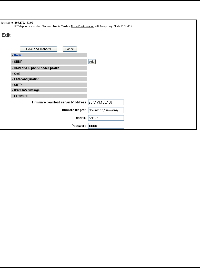
Page 418 of 910 Configuration of IP Telephony nodes using Element Manager
553-3001-365 Standard 4.00 August 2005
Figure 111
Configure file server
UFTP
IP Phones use UNIStim File Transfer Protocol (UFTP) to transfer the
firmware; therefore, the customer’s network must support UFTP. The
customer's network must open port 5105.
Note: If the firmware cannot be transferred due to firewall restrictions
(such as when the IP Phone is behind a firewall that has port 5105
blocked), then upgrade the IP Phone with the current firmware version
before distributing the telephone.
Default location of firmware files
The default location of the firmware files is different depending on the system
configuration, due to limitations of the various platforms:
• Signaling Server:

Configuration of IP Telephony nodes using Element Manager Page 419 of 910
IP Line Description, Installation and Maintenance
— The firmware file is stored on the Signaling Server in the “/u/fw”
directory.
• node using a Voice Gateway Media Card as the Leader card (the files can
be located in any of the following locations):
— The firmware files can be retrieved from the system's Signaling
Server.
— If the Voice Gateway Media Card is a Media Card, the files are
placed in the /C:/fw directory on the card.
— If the Voice Gateway Media Card is an ITG-P 24-port card, the files
attempt to store in the /C:/fw directory on the card. If there is not
enough storage space, the files can be stored on a PC Card plugged
into the card faceplate (/A: drive).
— The files can be placed on an alternate file server.
IP Phone firmware upgrade from a new
Voice Gateway Media Card
Use Element Manager to upgrade the IP Phone firmware files to the new
Voice Gateway Media Card. See Procedure 46 on page 438.
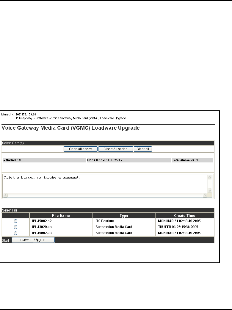
Page 420 of 910 Configuration of IP Telephony nodes using Element Manager
553-3001-365 Standard 4.00 August 2005
Determine Voice Gateway Media Card software version
To determine the version of software on the Voice Gateway Media Card,
follow the steps in Procedure 39.
Procedure 39
Determining card software version
1In the Element Manager navigator, click IP Telephony > Software >
Voice Gateway Media Card.
The Voice Gateway Media Card (VGMC) Loadware Upgrade window
opens. See Figure 112.
Figure 112
Voice Gateway Media Card (VGMC) Loadware Upgrade window
2Expand the node by clicking the plus sign (+) to the left of the node.
See Figure 113 on page 421.
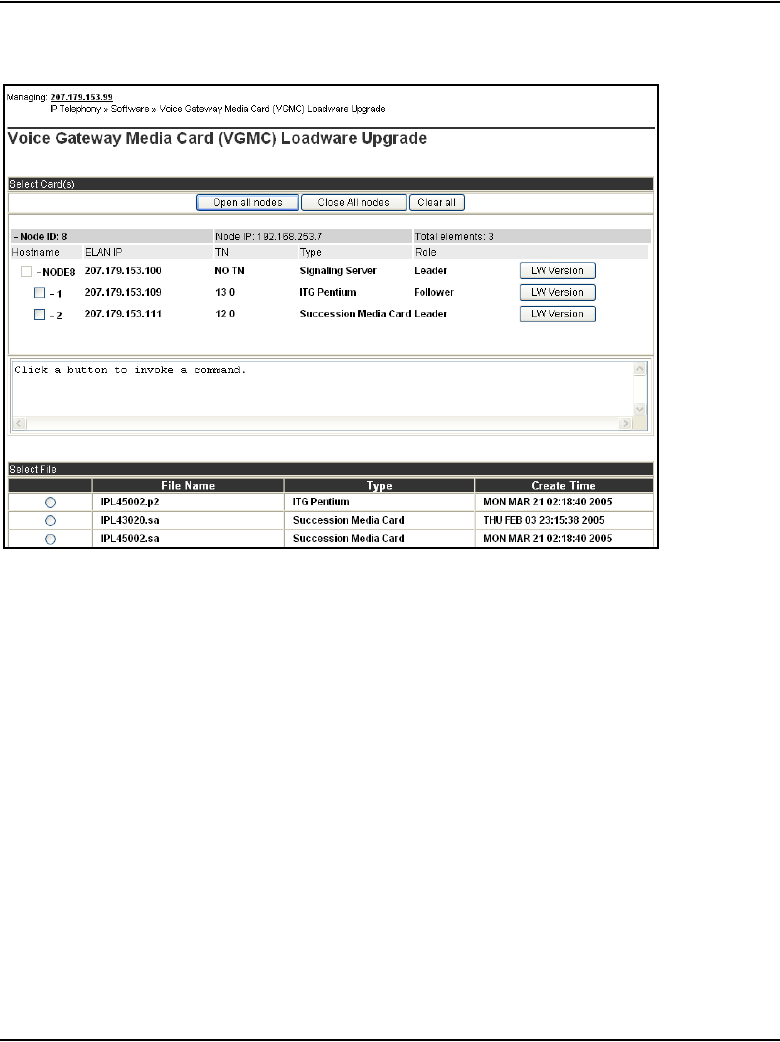
Configuration of IP Telephony nodes using Element Manager Page 421 of 910
IP Line Description, Installation and Maintenance
Figure 113
Voice Gateway Media Card (VGMC) Loadware Upgrade window – expanded
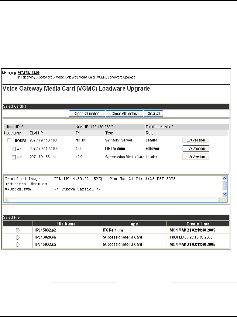
Page 422 of 910 Configuration of IP Telephony nodes using Element Manager
553-3001-365 Standard 4.00 August 2005
3Click the LW Version button located to the right of the card information.
The software version running on the card is displayed in the pane in the
center of the Voice Gateway Media Card (LW) Upgrade window under
the list of cards. See Figure 114. In this example, the software version
displayed is for the Media Card 32-port card.
Figure 114
LW version for the ITG Pentium
4Note the software version for the card.
End of Procedure
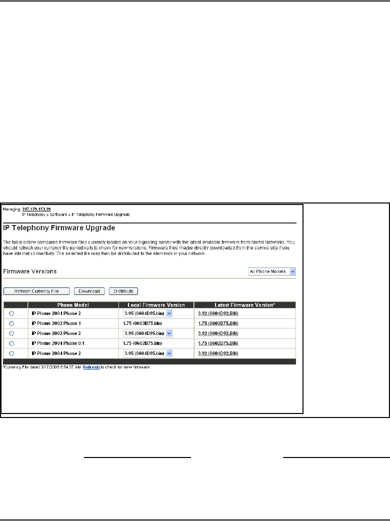
Configuration of IP Telephony nodes using Element Manager Page 423 of 910
IP Line Description, Installation and Maintenance
Determine the IP Phone firmware version
To determine the version of IP Phone firmware on the Voice Gateway Media
Card, follow the steps in Procedure 40.
Procedure 40
Determining the IP Phone firmware version
1In the Element Manager navigator, click IP Telephony > Software >
Telephony Firmware.
The Telephony Firmware window opens. See Figure 115.
The current local firmware versions are displayed in the Local Firmware
Version column.
Figure 115
Telephony Firmware window
2Note the firmware version for the card.
End of Procedure

Page 424 of 910 Configuration of IP Telephony nodes using Element Manager
553-3001-365 Standard 4.00 August 2005
Download the current loadware and IP Phone firmware
To check for the latest loadware and IP Phone firmware releases on the Nortel
Customer Support web site, follow the steps in Procedure 41.
Procedure 41
Downloading loadware and firmware from the Nortel web site
1Check the Nortel Customer Support web site for the latest IP Line 4.5
loadware and IP Phone firmware releases. See Appendix F: “Download
IP Line 4.5 files from Nortel web site” on page 903.
Note: The IP Line 4.5 loadware and IP Phone firmware files are
contained in the SSE-4.50.xx Signaling Server CD Image file in the “CS
1000” product list on the Nortel web site. The file contains:
•The IPL450xx.p2 and IPL450xx.sa loadware files. The IPL450xx.p2
file is the IP Line application for the ITG-P 24-port card and the
IPL450xx.sa is the IP Line application for the Media Card.
•The 0602Bxx.BIN (Phase I IP Phone 2004), 0603Bxx.BIN (Phase I
IP Phone 2002), and 0604Dnn.BIN (Phase II IP Phone 2001,
IP Phone 2002, and IP Phone 2004) firmware files.
For example, a firmware version can be labelled 0602B75 or
0603B75. This means IP Phone firmware version 1.38.
— The 02 represents the IP Phone 2004 and 03 is the IP Phone
2002.
— The letter B represents the version number 1.
— 75 represents the release number .75.
•A readme.txt file. The readme.txt file explains important
considerations for installing the new loadware and firmware versions.
The readme file also includes identifying information for the loadware
and firmware files such as the date and time, size and checksum.
2Compare the latest loadware and firmware versions available to the
loadware and firmware versions currently installed on the Voice Gateway
Media Card and the IP Phones.

Configuration of IP Telephony nodes using Element Manager Page 425 of 910
IP Line Description, Installation and Maintenance
3If more recent files are available, download the SSE-4.50.xx Signaling
Server CD Image file.
End of Procedure
Upload the loadware and firmware files to the file server
The next step is to upload the files from the Element Manager PC to the file
server. The Centralized File Upload window enables loadware and
firmware to be uploaded and stored on the Signaling Server. These files can
then be downloaded to the IP Phones and the Voice Gateway Media Cards
using the firmware and loadware upgrade functions available from the
Software Upgrade menu. The Signaling Server can be used as a central
distribution point to load and activate loadware, firmware and patches. To
upload the files, follow the step in Procedure 42 on page 426.
Note: For patches, Element Manager does not need to upload to
Signaling Server first. The Signaling Server obtains the patch file from
the Element Manager PC directly.
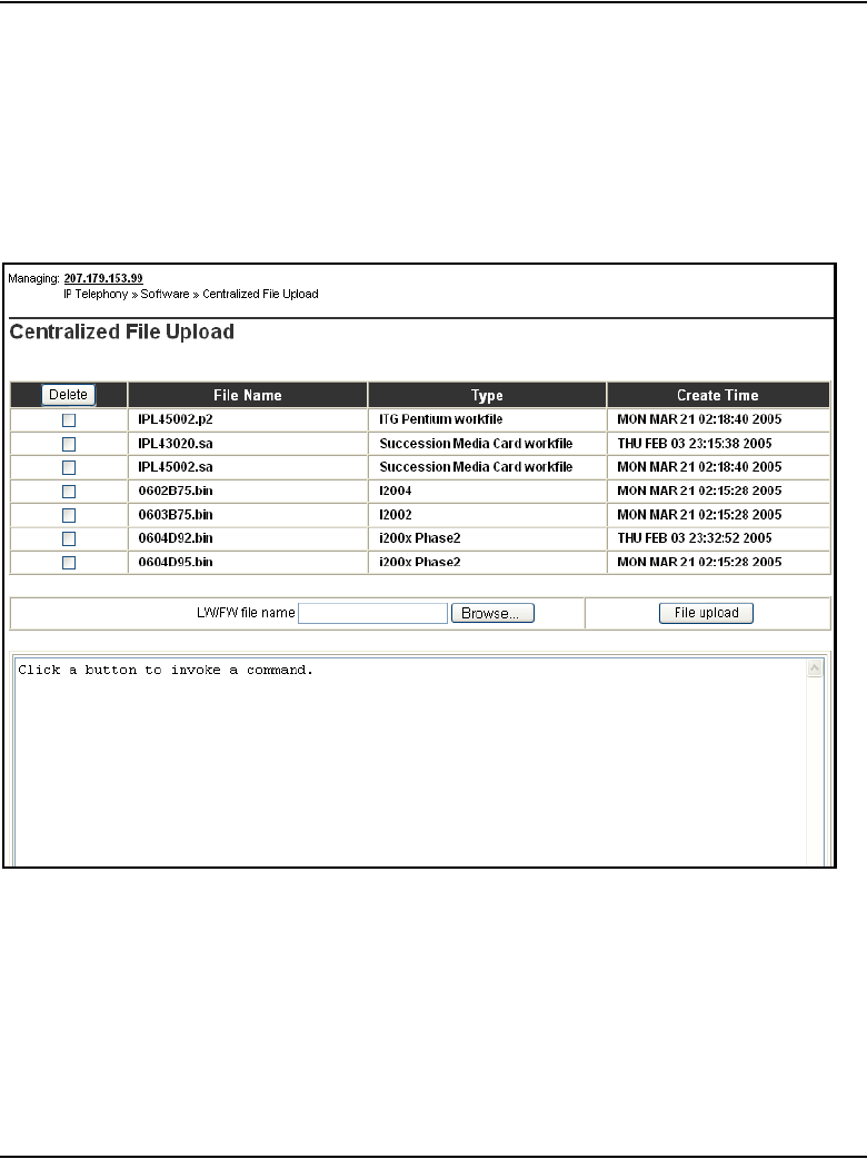
Page 426 of 910 Configuration of IP Telephony nodes using Element Manager
553-3001-365 Standard 4.00 August 2005
Procedure 42
Uploading loadware and firmware files
1In the Element Manager navigator, click IP Telephony > Software > File
Upload.
The Centralized File Upload window opens. See Figure 116.
Figure 116
Centralized File Upload window
2Click Browse.
The Choose File window opens. In the Choose File window, select the
path and file to upload. Alternatively, enter the path and filename for the
file to be uploaded.
Note: Only one loadware or firmware file can be uploaded at a time.

Configuration of IP Telephony nodes using Element Manager Page 427 of 910
IP Line Description, Installation and Maintenance
Once selected, the path and file name appear in the text box to the left of
the Browse button.
See Figure 117.
Figure 117
Firmware file text box
3Click File Upload.
The file appears in the list at the top of the window when it is uploaded.
Note: To delete older versions of the firmware and loadware files, select
the check box associated with the older file and click the Delete button
located at the top of the column of check boxes.
End of Procedure
Upgrade the Voice Gateway Media Card loadware
Once the files are uploaded to the file server, the Voice Gateway Media Cards
must be upgraded to the newest loadware version. To upgrade the card
loadware, follow the steps in Procedure 43.
Procedure 43
Upgrading the card loadware
1In the Element Manager navigator, click IP Telephony > Software >
Voice Gateway Media Card.
The Voice Gateway Media Card (VGMC)) Loadware Upgrade window
opens. See Figure 118 on page 428.
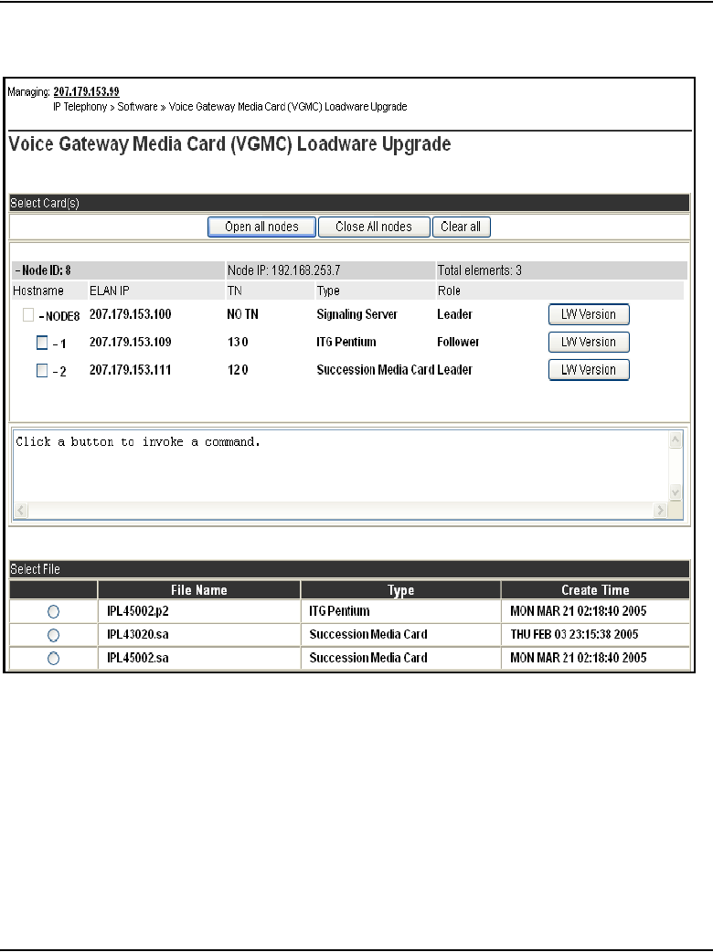
Page 428 of 910 Configuration of IP Telephony nodes using Element Manager
553-3001-365 Standard 4.00 August 2005
Figure 118
Voice Gateway Media Card (VGMC) Loadware Upgrade window
2Expand the node by clicking the plus sign (+) to the left of the node.
3Select the card(s) to upgrade by selecting the check box to the left of the
card information.
Note: Element Manager supports upgrading the software on up to four
cards at the same time.
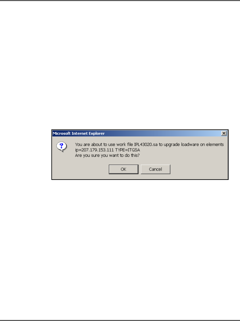
Configuration of IP Telephony nodes using Element Manager Page 429 of 910
IP Line Description, Installation and Maintenance
4In the lower part of the window, click the radio button of the most current
software version.
Note: If the card receiving the upgrade is an ITG-P 24-port line card,
select the radio button next to the most current version of the ITG-P
24-port line card software (IPL450xx.p2). If the card receiving the upgrade
is a Media Card, select the radio button next to the must current version
of the Media Card software (IPL450xx.sa).
In the example shown in Figure 118 on page 428, the Media Card check
box was selected and, at the bottom of the window, the Media Card
loadware file radio button was selected.
5Click Loadware Upgrade at the bottom left of the window.
A confirmation dialog box appears similar to the dialog box in Figure 119.
Figure 119
Loadware Upgrade confirmation dialog box
6Click OK to confirm the card upgrade.
The upgrade begins.
The Loadware Upgrade Progress window opens. See Figure 120 on
page 430.
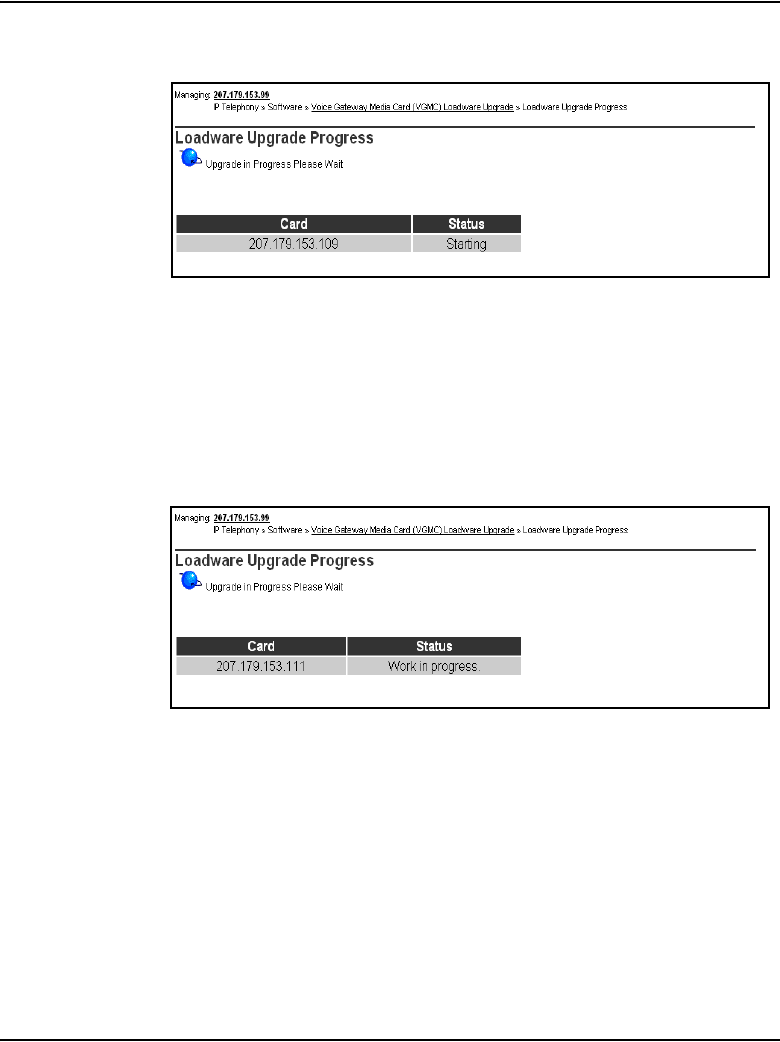
Page 430 of 910 Configuration of IP Telephony nodes using Element Manager
553-3001-365 Standard 4.00 August 2005
Figure 120
Loadware Upgrade Progress window - starting
The status of the upgrade is shown for each of the cards selected to
receive the loadware upgrade. This status of the upgrade can be Work in
progress, Upgrading, Fail, or Finished. See Figure 121 on this page and
Figure 122 on page 431.
Figure 121
Loadware Upgrade Progress – upgrade progress
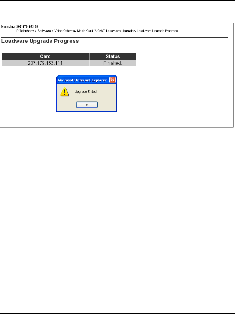
Configuration of IP Telephony nodes using Element Manager Page 431 of 910
IP Line Description, Installation and Maintenance
Figure 122
Loadware Upgrade Progress – upgrade ended
7Click OK.
8Repeat steps 3-7 for the other card(s) that have to be upgraded.
End of Procedure

Page 432 of 910 Configuration of IP Telephony nodes using Element Manager
553-3001-365 Standard 4.00 August 2005
Reboot the Voice Gateway Media Card
Follow the steps in Procedure 44 to reboot a Voice Gateway Media Card.
Procedure 44
Rebooting the Voice Gateway Media Card
1Disable the Voice Gateway Media Card.
2Click the Element Manager navigator, click IP Telephony > Nodes:
Servers, Media Cards > Maintenance and Reports.
The Node Maintenance and Reports window opens.
3To expand the node containing the card to be rebooted, click the plus sign
(+) to the left of the node.
4Click the Voice Gateway Media Card’s associated Reset button to reboot
the card.
Note 1: The cards remain in the “Disabled” state after the upgrade, so a
“Reset” command can be used. The cards can also be reset by using a
pointed object to press the Reset button on the card’s faceplate.
Note 2: Reboot the Leader card only if the node is using the Voice
Gateway Media Card as the Leader; that is, the Signaling Server is not
the Leader.
5Click the card’s Status button in the Node Maintenance and Reports
window to verify the status of the Voice Gateway Media Card.
In the example shown in Figure 123 on page 433, the Media Card’s status
is displayed, showing that it is enabled.
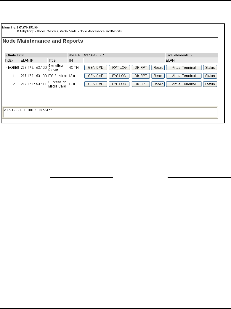
Configuration of IP Telephony nodes using Element Manager Page 433 of 910
IP Line Description, Installation and Maintenance
Figure 123
Voice Gateway Media Card status
6Use the LD 32 ENLC command to re-enable the Voice Gateway Media
Cards.
7Repeat these steps for each Voice Gateway Media Card that received the
software upgrade.
End of Procedure
Re-enable the Voice Gateway Media Card
Follow the steps in Procedure 45 to re-enable the Voice Gateway Media
Card(s).
Procedure 45
Re-enabling the Voice Gateway Media Card
1In the Element Manager navigator, click System > Maintenance.
The Maintenance window opens. See Figure 124 on page 434.
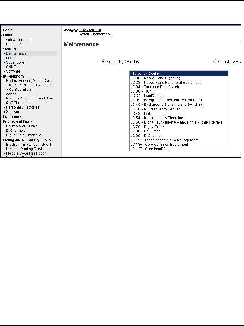
Page 434 of 910 Configuration of IP Telephony nodes using Element Manager
553-3001-365 Standard 4.00 August 2005
Figure 124
Maintenance window
2From the Select by Overlay drop-down list, select LD 32 - Network and
Peripheral Equipment.
The Network and Peripheral Diagnostics window opens. See
Figure 125 on page 435.
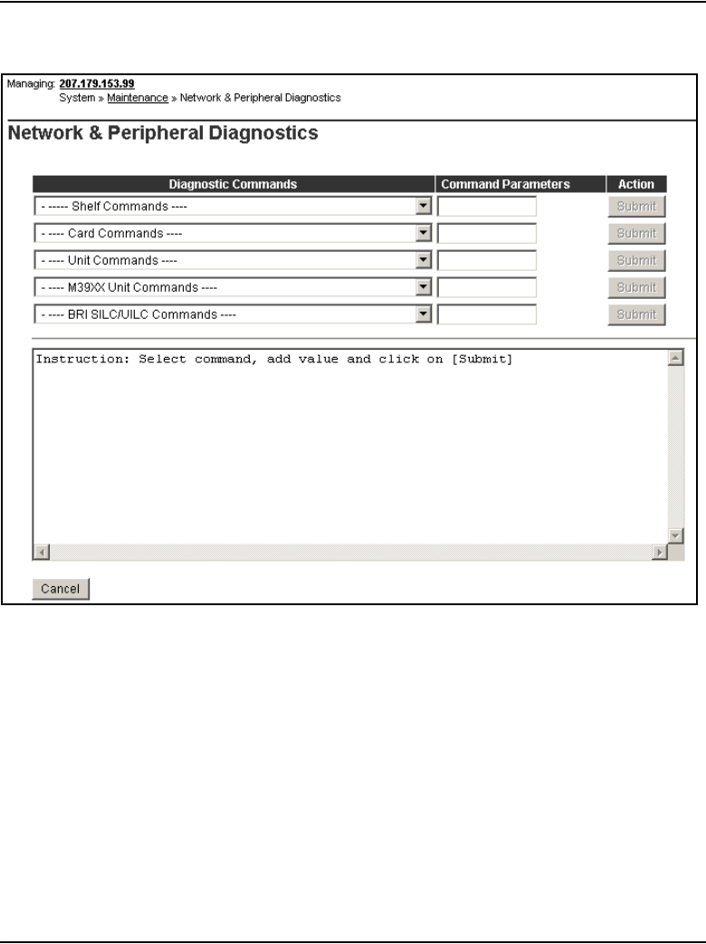
Configuration of IP Telephony nodes using Element Manager Page 435 of 910
IP Line Description, Installation and Maintenance
Figure 125
Network and Peripheral Diagnostics window
3From the Card Commands drop-down list, under General Card
Commands, select ENLC - Enable and reset card.
See Figure 126 on page 436.

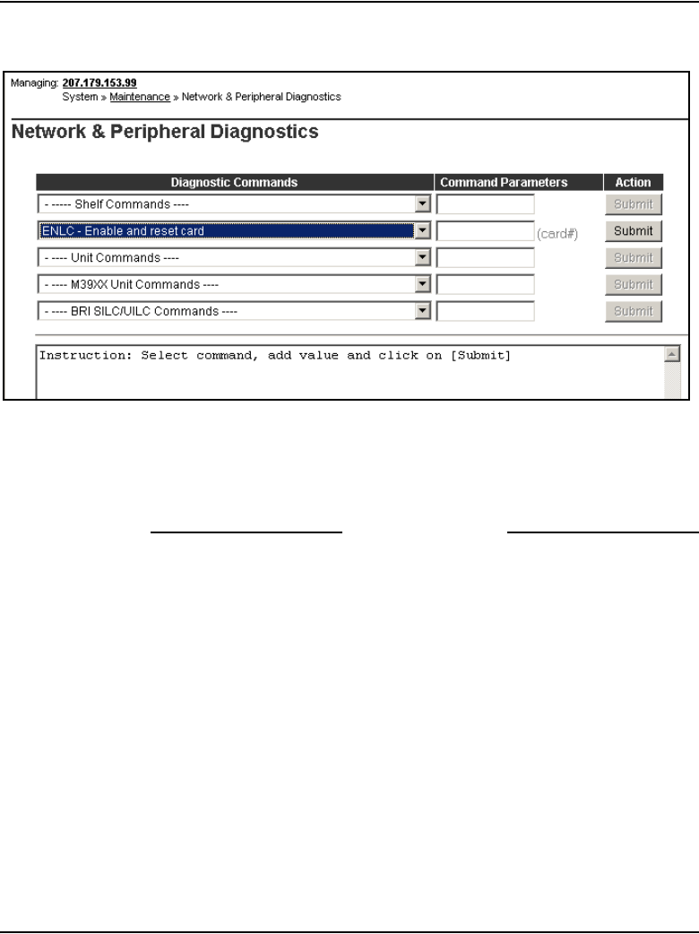
Configuration of IP Telephony nodes using Element Manager Page 437 of 910
IP Line Description, Installation and Maintenance
Figure 127
Command Parameters
5Click Submit.
6Repeat Steps 3 – 5 for each Voice Gateway Media Card to be re-enabled.
End of Procedure
Upgrade the IP Phone firmware
When the IP Line 4.5 loadware has been upgraded on the Voice Gateway
Media Cards, determine if an IP Phone firmware upgrade is also required. If
an upgrade is required, the Voice Gateway Media Cards must be upgraded to
the newest IP Phone firmware version. To upgrade the firmware required for
the IP Phones, follow the steps in Procedure 46 on page 438. This procedure
has two major components:
• loading the IP Phone firmware onto each Voice Gateway Media Card in
the node
• propagating the firmware from the Voice Gateway Media Card to each
IP Phone registered on that card

Page 438 of 910 Configuration of IP Telephony nodes using Element Manager
553-3001-365 Standard 4.00 August 2005
Note: A firmware download does not occur with IP Phones performing
a Virtual Office login or Media Gateway 1000B (MG 1000B) login to a
remote system. No firmware upgrade takes place during a Virtual Office
Login or MG 1000B user registration with the LTPS. The registration is
allowed because the IP Phone firmware version must be 1.33 or later to
perform a Virtual Office login or MG 1000B user registration.
The umsUpgradeAll command has no impact on Virtual Office Login
IP Phones. These IP Phones are not reset. If the Virtual Office Login is
on the same Call Server, then the IP Phone firmware is upgraded after the
user logs out. If the Virtual Office Login is between different Call
Servers, then the IP Phone just registers back to its home LTPS and
follows the normal firmware rules for regular registration.
When the umsUpgradeAll command is executed, MG 1000B user
IP Phones that are on active calls are flagged. After the IP Phones
become idle, the IP Phones are switched by the Call Server back to the
MG 1000B for the firmware upgrade.
Follow the steps in Procedure 46 to upgrade IP Phone firmware
Procedure 46
Upgrading the IP Phone firmware
1Disable the Voice Gateway Media Cards before updating the firmware.
Use the LD 32 DISI command to disable the card.
2Verify that all Voice Gateway Media Cards that require a firmware
upgrade have established a signaling link with the Call Server.
To verify the link is available between the Call Server and the card, Telnet
to each card and log into the card. From the command line, type
pbxLinkShow. The status of the Call Server link appears. If the link is
active the window displays the following:
RUDPLinkState = Up
3In the Element Manager navigator, click IT Telephony > Software >
Telephony Firmware.
The Telephony Firmware window opens. See Figure 128 on page 439.
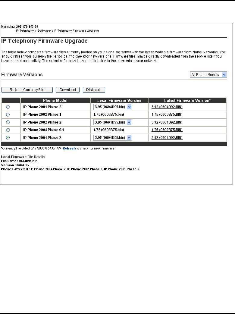
Configuration of IP Telephony nodes using Element Manager Page 439 of 910
IP Line Description, Installation and Maintenance
Figure 128
Telephony Firmware window
4Select the radio button of the firmware to be distributed.
5Click Distribute.
The Distribute Firmware window opens. See Figure 129 on page 440.
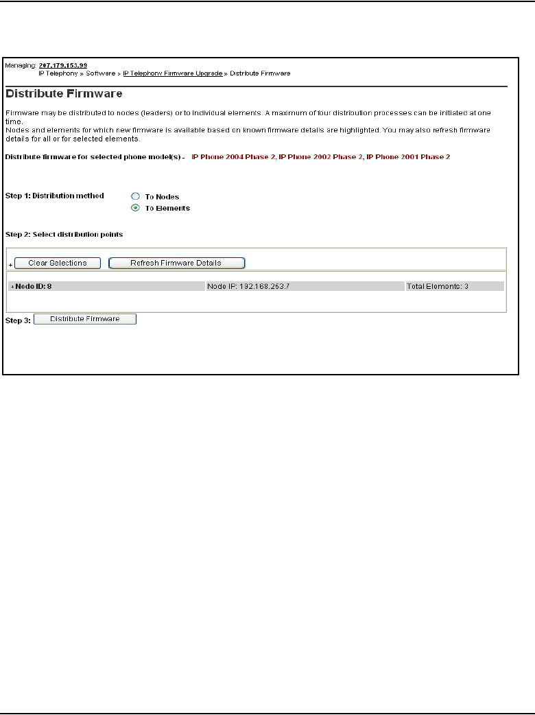
Page 440 of 910 Configuration of IP Telephony nodes using Element Manager
553-3001-365 Standard 4.00 August 2005
Figure 129
Distribute Firmware window
The firmware to be distributed is displayed in red.
6In the Step 1: Distribution method section, click the Distribute to
Elements radio button.
7In the Step 2: Select distribution points: section, expand the node
containing the cards that are to receive the IP Phone firmware upgrade by
clicking the plus sign (+) to the left of the Node ID.
8Select the card(s) to upgrade by selecting the check box to the left of the
card information. See Figure 130 on page 441.
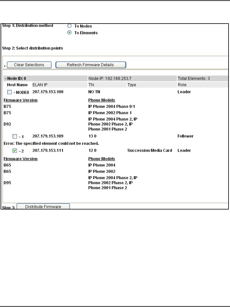
Configuration of IP Telephony nodes using Element Manager Page 441 of 910
IP Line Description, Installation and Maintenance
Figure 130
Distribute Firmware window with selected card
Note: Element Manager can upgrade the firmware on a maximum of four
cards at the same time.
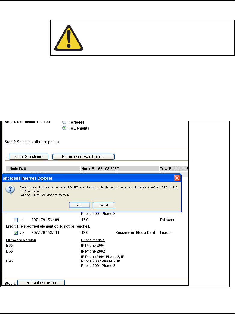
Page 442 of 910 Configuration of IP Telephony nodes using Element Manager
553-3001-365 Standard 4.00 August 2005
9Click Distribute Firmware.
A confirmation dialog box appears, similar to the confirmation dialog box
in Figure 131.
10 Click OK to confirm the firmware upgrade to the card.
The upgrade begins.
Figure 131
Firmware Upgrade confirmation dialog box
CAUTION
Downloading an incorrect version of the IP Phone
firmware can result in extended service interruptions and
can require special recovery procedures.
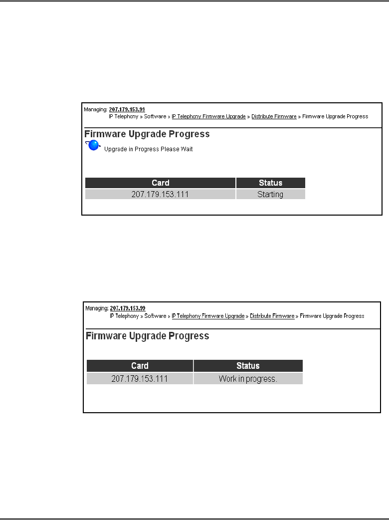
Configuration of IP Telephony nodes using Element Manager Page 443 of 910
IP Line Description, Installation and Maintenance
The Firmware Upgrade Progress window opens, indicating the upgrade
is starting. See Figure 132.
The status of the upgrade is shown for each of the cards selected to
receive the firmware upgrade.
Figure 132
Firmware Upgrade Progress – starting
The status of the upgrade continues to display as work in progress. See
Figure 133.
Figure 133
Firmware Upgrade Progress
When the firmware upgrade has finished, the Firmware Upgrade
Progress shows as finished. See Figure 134 on page 444.
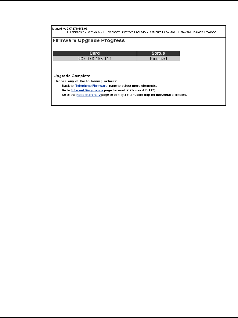
Page 444 of 910 Configuration of IP Telephony nodes using Element Manager
553-3001-365 Standard 4.00 August 2005
Figure 134
Firmware Upgrade Progress – finished
11 Repeat the preceding steps for all the card(s) that have to be upgraded.
The IP Phones continue to run the old firmware until each IP Phone
reregisters with a Voice Gateway Media Card containing the new
IP Phone firmware.
Note: Commands are available from the IPL> command line to upgrade
a single IP Phone immediately, all IP Phones immediately, or schedule all
IP Phones to be upgraded at a later time. Before doing this, verify that
each Voice Gateway Media Card has the correct IP Phone firmware
version.
12 Select an IP Phone for test purposes.
13 Telnet to the Voice Gateway Media Card and then log into the IPL>
command line, and enter the following:
isetReset “xxx.xxx.xxx.xxx”
where xxx.xxx.xxx.xxx is the IP Address of the selected telephone.
14 Monitor the display on the test telephone. As the IP Phone upgrades the
firmware, note the IP Address of the Voice Gateway Media Card from
which the telephone is receiving its upgrade.
15 Press the Services key (key with globe with arrow pointing East and West
on the IP Phone 2002/IP Phone 2004). The Services key enables access
to the Telephone Options list.
a. Press Select to select Telephone Options.
b. Use the Navigation keys to scroll to Set Info.

Configuration of IP Telephony nodes using Element Manager Page 445 of 910
IP Line Description, Installation and Maintenance
c. Press the Select softkey, then press the Navigation keys until it
displays FW Version:. Select the appropriate firmware on the
Voice Gateway Media Card
Note: For example, a firmware version can be labeled 0602B75 or
0603B75, which means IP Phone firmware version 1.38.
• 02 represents the IP Phone 2004 and 03 represents the IP Phone
2002.
• B represents the version number 1.
• 75 represents the release number .75.
16 Lift the handset of the IP Phone and make a call to verify the IP Phone
works.
17 Before proceeding, ensure the time on the Voice Gateway Media Card is
configured correctly. Telnet to each Voice Gateway Media Card and log
in. At the IPL> command line, enter the following:
umsUpgradeAll “hh:mma/p”
hh:mma/p specifies the time when the upgrade will occur, a represents
a.m., and p represents p.m. The time is in Standard format.
For example, umsUpgradeAll “11:30a” or umsUpgradeAll “2:45p”.
At the time specified, all the IP Phones registered to the Voice Gateway
Media Card go out of service. This can take several minutes.
Upon completion of the firmware upgrade, the IP Phones are brought
back online in groups of ten.
After the test telephone is working, the umsUpgradeAll command does
not require the time parameter. However, if the time parameter is not
used, the command immediately resets all the IP Phones currently
registered on that Voice Gateway Media Card.
CAUTION
If the umsUpgradeAll command is used without the time
parameter, all IP Phones registered on cards that are
logged into are immediately taken out of service. Use the
time parameter with the command to prevent this from
happening.

Page 446 of 910 Configuration of IP Telephony nodes using Element Manager
553-3001-365 Standard 4.00 August 2005
To schedule a specific reset time for the IP Phones, instead of resetting
them immediately, check the time on all the Voice Gateway Media Cards.
Reset the time, if necessary, to ensure all Voice Gateway Media Cards
have the same time, and then issue the umsUpgradeAll “hh:mma/p”,
where “hh:mma/p” represents the time the upgrade is scheduled to occur.
18 At the IPL> prompt, verify the IP Phones for each Voice Gateway Media
Card are upgraded by entering the following:
isetShow
19 Inspect the list to ensure all IP Phones have the correct firmware version.
20 For any IP Phones that did not upgrade successfully, try one of the
following (in order):
•Use the isetReset ''IP Address'' command.
• Enter the following combination of key strokes at the telephone
console: release, mute, up, down, up, down, up, mute, 9, release.
• Power the telephone off and then on again.
If the upgrade was unsuccessful on any of the IP Phones, the cause is
probably due to one of the following:
• One of the Voice Gateway Media Cards did not upgrade its software
successfully.
• An IP Phone’s firmware version was unable to be upgraded by the
Voice Gateway Media Card in the normal manner.
•The umsUpgradeAll command has not been issued.
• One of the cards might not have been reset.
If the upgrade was unsuccessful, re-do the appropriate procedure. If
the upgrade is still unsuccessful, contact a technical support
representative for further assistance.
End of Procedure
For additional information on configuring the IP Phones, refer to IP Phones:
Description, Installation, and Operation (553-3001-368).

Configuration of IP Telephony nodes using Element Manager Page 447 of 910
IP Line Description, Installation and Maintenance
Upgrade the Voice Gateway Media Card firmware
The minimum versions of IP Line 4.5 firmware for the Voice Gateway Media
Card are:
• Version 6.8 for the NTVQ01AA and NTVQ01BA Media Card hardware
platform
• Version 8.2 for the NTVQ01AB and NTVQ01BB Media Card hardware
platform
• Version 5.7 for the ITG-P 24-port card
Note: Firmware versions 6.x and 8.x can only be used for the specified
Media Card hardware platforms. They cannot be used interchangeably.
To upgrade the card firmware, follow the steps in Procedure 47.
Procedure 47
Upgrading the Voice Gateway Media Card firmware
1Check the Nortel web site for the most current versions of the firmware for
the ITG-P 24-port line card and Media Cards.
2Once the most current version of the firmware has been downloaded,
follow the steps in:
• Procedure 105 on page 763 to upgrade the firmware on the ITG-P
24-port line card
• Procedure 106 on page 766 to upgrade the firmware on the Media
Cards
End of Procedure

Page 448 of 910 Configuration of IP Telephony nodes using Element Manager
553-3001-365 Standard 4.00 August 2005
Configure Alarm Management to receive IP Line
SNMP traps
Alarm Management cannot be configured using Element Manager. OTM 2.2
must be used to configure the Alarm Management feature to receive IP Line
SNMP traps. See Procedure 68 on page 523.
Assemble and install an IP Phone
To assemble and install an IP Phone, refer to IP Phones: Description,
Installation, and Operation (553-3001-368).
Change the default IPL> CLI Shell password
The IPL> Command Line Interface (CLI) is password-protected to control
Telnet access and access to the local maintenance port. The same user name
and password also controls FTP access to the Voice Gateway Media Card.
The IPL> CLI has a default user name of itgadmin and a default password of
itgadmin.
The default user name and password must be changed as a preventative
security measure. See “IPL> CLI Shell user name and password” on page 539
and Procedure 69 on page 553.
Configure the IP Phone Installer Passwords
The IP Phone Installer Password, used when changing the TN on the
telephone, controls registration with a virtual line TN on the Call Server.
Refer to page 543 for more information about the IP Phone Installer
Passwords.
To enable and set the administrative IP Phone Installer Password, see
Procedure 69 on page 553.
If required, enable and configure a temporary IP Phone Installer Password.
See Procedure 70 on page 556.

Configuration of IP Telephony nodes using Element Manager Page 449 of 910
IP Line Description, Installation and Maintenance
Element Manager can also be used to configure the IP Phone Installer
Passwords. See “Setting the IP Phone Installer Password” on page 627.
Import node configuration from an existing node
It is possible to import a node and its configuration data from an existing node
into Element Manager.
For example, if Node 151 exists, but does not exist on the Call Server, then
Node 151 can be imported into Element Manager. Once imported, the node
configuration data can be updated and edited.
Procedure 48
Importing node files
1In the Element Manager navigator, click IP Telephony > Nodes:
Servers, Media Cards > Configuration.
The Node Configuration window opens.
2Click Import Node Files.
The Import Node Files window opens. See Figure 135 on page 450.
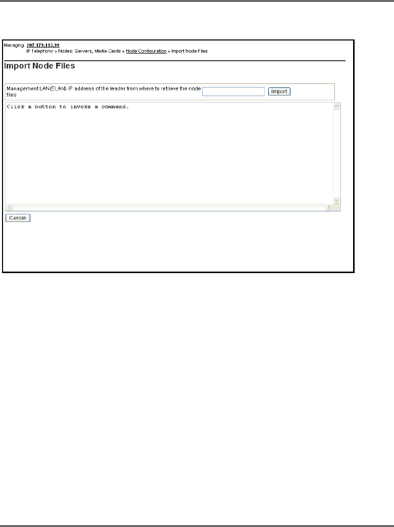
Page 450 of 910 Configuration of IP Telephony nodes using Element Manager
553-3001-365 Standard 4.00 August 2005
Figure 135
Import node files
3Enter the Management LAN (ELAN) network interface IP address of the
Leader card in the text box. This address is used to retrieve the node files.
4Click the Import button.
If the node already exists on the Call Server, a message appears
indicating that the node already exists on the Call Server. See Figure 136
on page 451.
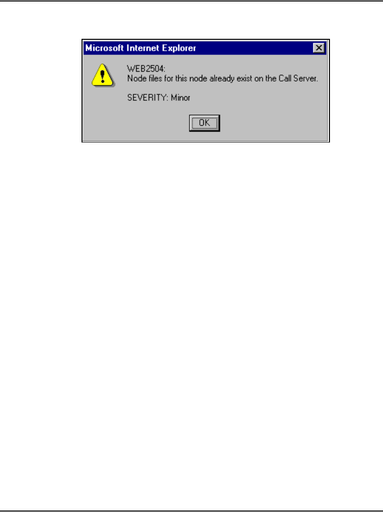
Configuration of IP Telephony nodes using Element Manager Page 451 of 910
IP Line Description, Installation and Maintenance
Figure 136
Duplicate node information
If the node does not exist, Element Manager tries to write the
configuration to the Call Server. If it succeeds, a message indicating the
import was successful appears. See Figure 137 on page 452. If Element
Manager cannot write the configuration to the Call Server, a fail reason
appears in the text area of the Import Node Files window.
If the import is successful, information appears in the text area of the
Node Import Files screen. See Figure 137 on page 452.
A message box also appears. In the message box, click the OK button to
proceed to the Node Summary window. The node information can then
be viewed and, if necessary, edited.
If the node import is not successful, an error message appears in the text
box area.
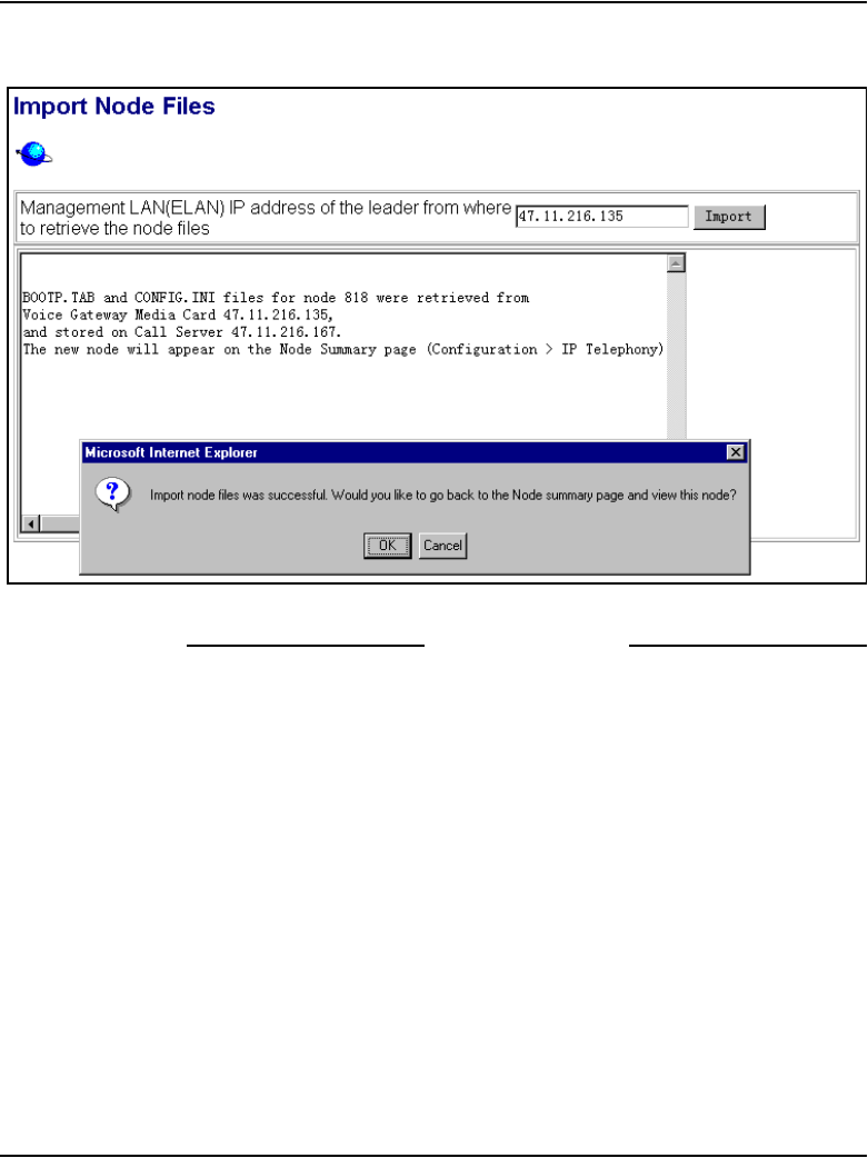
Page 452 of 910 Configuration of IP Telephony nodes using Element Manager
553-3001-365 Standard 4.00 August 2005
Figure 137
Import Node Files – successfully imported node
End of Procedure

Page 453 of 910
IP Line Description, Installation and Maintenance
530
Configuration of IP Telephony nodes
using OTM 2.2
Contents
This section contains information on the following topics:
Introduction . . . . . . . . . . . . . . . . . . . . . . . . . . . . . . . . . . . . . . . . . . . . . . 454
Configure IP Line data using OTM. . . . . . . . . . . . . . . . . . . . . . . . . . . . 454
Launch OTM and the IP Line 4.5 application . . . . . . . . . . . . . . . . . 456
Add a site, system, and customer . . . . . . . . . . . . . . . . . . . . . . . . . . . 458
Manually add an IP Telephony node . . . . . . . . . . . . . . . . . . . . . . . . 464
Configure the card properties of the Voice Gateway Media Card . . 469
Configure DSP profile data . . . . . . . . . . . . . . . . . . . . . . . . . . . . . . . 472
Configure SNMP traps and ELAN gateway routing table . . . . . . . . 476
Configure node synchronization with the Call Server . . . . . . . . . . . 480
Configure the Call Server ELAN network interface IP address and the
TLAN voice port . . . . . . . . . . . . . . . . . . . . . . . . . . . . . . . . . . . . . . . . . . . . . . . . . . . . 483
Configure security for SNMP access . . . . . . . . . . . . . . . . . . . . . . . . 485
Configure SNMP access and community name strings . . . . . . . . . . 485
Configure SNMP trap destinations for an IP Telephony node. . . . . 488
Configure file server access . . . . . . . . . . . . . . . . . . . . . . . . . . . . . . . 491
Configure QoS . . . . . . . . . . . . . . . . . . . . . . . . . . . . . . . . . . . . . . . . . 493
Configure SNTP . . . . . . . . . . . . . . . . . . . . . . . . . . . . . . . . . . . . . . . . 495
Transmit node configuration from OTM 2.2
to the Voice Gateway Media Cards. . . . . . . . . . . . . . . . . . . . . . . . . . . . 496
Set the Leader 0 IP address . . . . . . . . . . . . . . . . . . . . . . . . . . . . . . . 497
Transmit node and card properties to Leader 0 . . . . . . . . . . . . . . . . 499
Transmit card properties to all cards in the node . . . . . . . . . . . . . . . 501

Page 454 of 910 Configuration of IP Telephony nodes using OTM 2.2
553-3001-365 Standard 4.00 August 2005
Upgrade the Voice Gateway Media Card software and IP Phone firmware . . . . . 504
IP Phone firmware installation and upgrade . . . . . . . . . . . . . . . . . . 504
IP Phone firmware upgrade from a new Voice Gateway Media Card . 506
Verify card software and IP Phone firmware. . . . . . . . . . . . . . . . . . 507
Upgrade options . . . . . . . . . . . . . . . . . . . . . . . . . . . . . . . . . . . . . . . . 511
Upgrade Voice Gateway Media Card software . . . . . . . . . . . . . . . . 512
Upgrade the Voice Gateway Media Card software . . . . . . . . . . . . . 515
Upgrade the IP Phone firmware. . . . . . . . . . . . . . . . . . . . . . . . . . . . 516
Configure OTM Alarm Management to receive IP Line SNMP traps. . . . 523
Assemble and install an IP Phone. . . . . . . . . . . . . . . . . . . . . . . . . . . . . 529
Change the default IPL> CLI Shell password . . . . . . . . . . . . . . . . . . . 529
Change the default IPL> CLI Shell password . . . . . . . . . . . . . . . . . . . 529
Introduction
This chapter explains how to configure IP Telephony nodes and Voice
Gateway Media Cards using Optivity Telephony Manager (OTM) 2.2.
This chapter also provides instruction for transmitting data to Voice Gateway
Media Cards, upgrading card software, and upgrading IP Phone firmware
using OTM.
Read about IP network engineering guidelines in Converging the Data
Network with VoIP (553-3001-160) before installing an IP Telephony node.
Configure IP Line data using OTM
OTM can be used to manually add and configure IP Telephony nodes. OTM
2.2 includes an IP Line 4.5 application that is used to configure nodes on
Meridian 1 systems. Multiple IP Telephony nodes for IP Phones are
configured and managed from the same OTM PC.

Configuration of IP Telephony nodes using OTM 2.2 Page 455 of 910
IP Line Description, Installation and Maintenance
Node definition
A node is defined as a collection of Signaling Servers and Voice Gateway
Media Cards (ITG-P 24-port line cards and Media Card 8-port and 32-port
line cards). Each node in the network has a unique Node ID. This Node ID is
an integer value. A node has only one primary or Leader Voice Gateway
Media Card. All the other Voice Gateway Media Cards are defined as
Followers.
Note 1: All IP addresses and subnet mask data must be in dotted decimal
format. Convert subnet mask data from Classless Inter-Domain (CIDR)
format.
Note 2: Refer to Table 57 on page 307 for IP addresses and information
required in this procedure.
WARNING
OTM 2.2 does not support configuration of nodes which
reside on a CS 1000 system. However, since OTM 2.2 is
required for retrieval of Operational Measurement (OM)
reports from nodes on these systems, OTM is capable of
being configured with basic network connection
information of the node. The necessary configuration to
retrieve the OM reports is covered in Procedure 49 on
page 456 through Procedure 53 on page 472. In these
procedures, pay special attention to any comments
specific to nodes which reside on a CS 1000 system.
Page 456 of 910 Configuration of IP Telephony nodes using OTM 2.2
553-3001-365 Standard 4.00 August 2005
Launch OTM and the IP Line 4.5 application
To launch OTM and start the IP Line 4.5 application, follow the steps in
Procedure 49.
Procedure 49
Launching OTM
1Select Start > Programs > Optivity Telephony Manager > OTM
Navigator.
2The OTM Login screen appears. See Figure 138.
Figure 138
OTM Login screen
3Enter the Login Name and Password. Click OK.
4The OTM Navigator window opens.
OTM Navigator has two tabs: Sites and Gatekeeper Zones. The IP Line
4.5 application, called IP Telephony, that is available with OTM is located
on the Sites tab. Click the Sites tab. See Figure 139 on page 457.
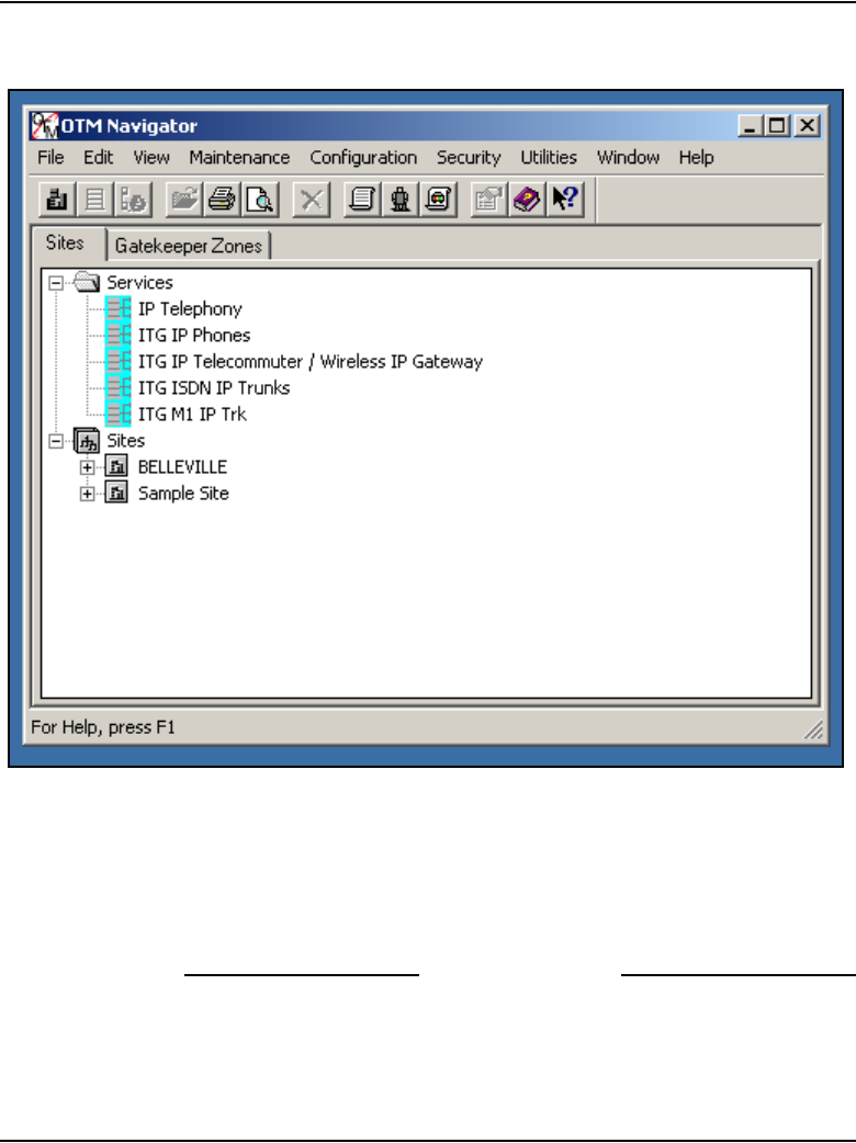
Configuration of IP Telephony nodes using OTM 2.2 Page 457 of 910
IP Line Description, Installation and Maintenance
Figure 139
OTM Navigator
5Expand the Services folder. Double-click the IP Telephony icon to launch
the IP Line 4.5 application. See Figure 139.
The IP Telephony window opens. This application is used to configure
and administer the IP Telephony nodes and the Voice Gateway Media
Cards.
End of Procedure
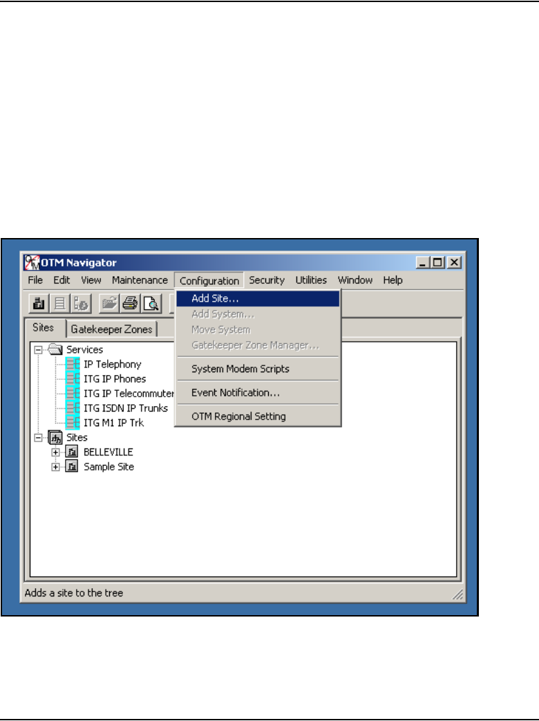
Page 458 of 910 Configuration of IP Telephony nodes using OTM 2.2
553-3001-365 Standard 4.00 August 2005
Add a site, system, and customer
A site, system, and customer must be added before nodes and Voice Gateway
Media Cards can be configured. Follow the steps in Procedure 50 to add a
site, system, and customer using OTM Navigator.
Procedure 50
Adding a site, system, and customer
1In the OTM Navigator window, click Configuration > Add Site. See
Figure 140.
Figure 140
OTM Navigator – Configuration > Add Site
The New Site Properties window opens. See Figure 141 on page 459.
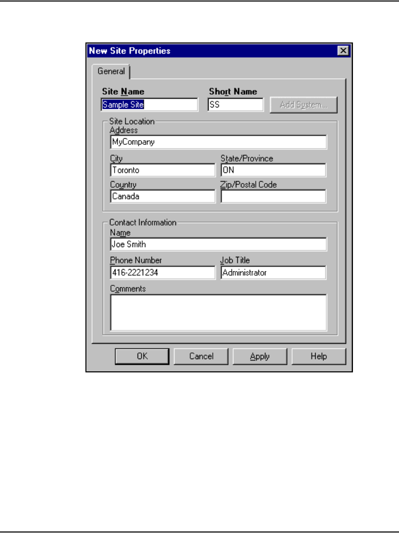
Configuration of IP Telephony nodes using OTM 2.2 Page 459 of 910
IP Line Description, Installation and Maintenance
Figure 141
New Site Properties window
2In the New Site Properties window, configure the following:
a. Site Name: Enter the name of the site.
b. Short Name: Enter a short name for the site.
c. Under Site Location, add the Address, City, State/Province,
Country, and Zip/Postal Code of the site.
d. Under Contact Information, add the Name, Phone Number, Job
Title, and any Comments for the site contact person(s).
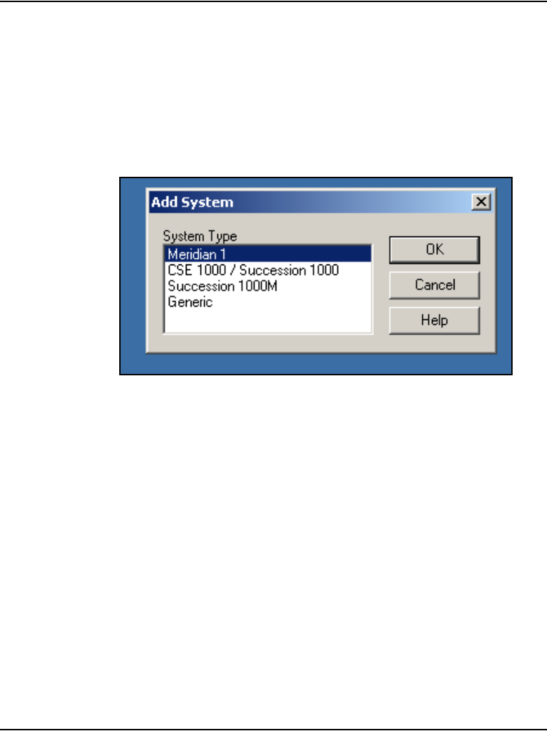
Page 460 of 910 Configuration of IP Telephony nodes using OTM 2.2
553-3001-365 Standard 4.00 August 2005
3Click Apply.
The Add System button (located in the upper right corner of the New Site
Properties window) is enabled.
4Click the Add System button.
The Add System dialog box opens. See Figure 142.
Figure 142
Add System
5In the Add System dialog box, select the system and click OK.
The New System Properties window opens. See Figure 143 on
page 461.
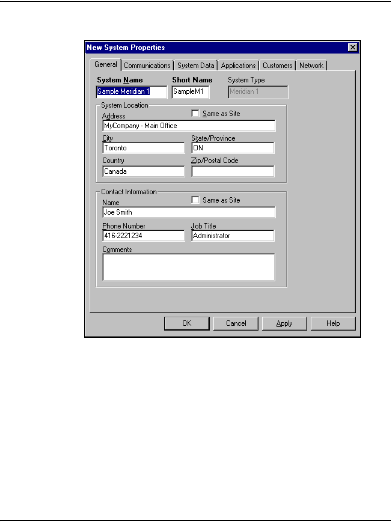
Configuration of IP Telephony nodes using OTM 2.2 Page 461 of 910
IP Line Description, Installation and Maintenance
Figure 143
New System Properties window
6In the New System Properties window, configure the following:
a. System Name: Enter the name of the system.
b. Short Name: Enter a short name for the system.
7Click Apply.
The System Properties window opens.
8Click the Customers tab and then click the Add button.
The Add Customer dialog window appears. See Figure 144 on
page 462.
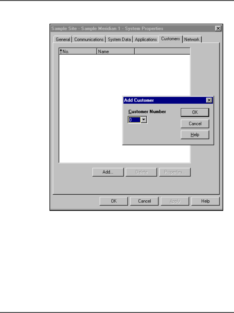
Page 462 of 910 Configuration of IP Telephony nodes using OTM 2.2
553-3001-365 Standard 4.00 August 2005
Figure 144
System Properties window – Add Customer
9Select the Customer Number. Click OK.
This adds a customer to the system and opens the New - (Customer n)
Properties window.
10 Click OK.
The System Properties window opens.
11 Click OK to save and close the System Properties.

Configuration of IP Telephony nodes using OTM 2.2 Page 463 of 910
IP Line Description, Installation and Maintenance
Note: Only the Customer Number is required to add a system. There is
no need to enter any other customer data. The other data in the Customer
tab and other System Properties tabs is not required for the IP Line 4.5
application. This data is used by other OTM applications.
End of Procedure
The following is a summary of steps required to configure a Voice Gateway
Media Card using OTM 2.2:
1“Manually add an IP Telephony node” on page 464.
2“Configure the card properties of the Voice Gateway Media Card” on
page 469.
3“Configure DSP profile data” on page 472.
4“Configure SNMP traps and ELAN gateway routing table” on page 476.
5“Configure the Call Server ELAN network interface IP address and the
TLAN voice port” on page 483.
6“Configure security for SNMP access” on page 485.
7“Configure file server access” on page 491.
8“Configure QoS” on page 493.

Page 464 of 910 Configuration of IP Telephony nodes using OTM 2.2
553-3001-365 Standard 4.00 August 2005
Manually add an IP Telephony node
Follow the steps in Procedure 51 to manually add an IP Telephony node.
Procedure 51
Adding an IP Telephony node manually
1In the OTM Navigator window, click on the Services folder.
2Double-click the IP Telephony icon. See Figure 139 on page 457.
The IP Telephony window opens.
3Click Configuration > Node > Add. See Figure 145.
Figure 145
IP Telephony main window
The Add Node dialog box opens.See Figure 146 on page 465.
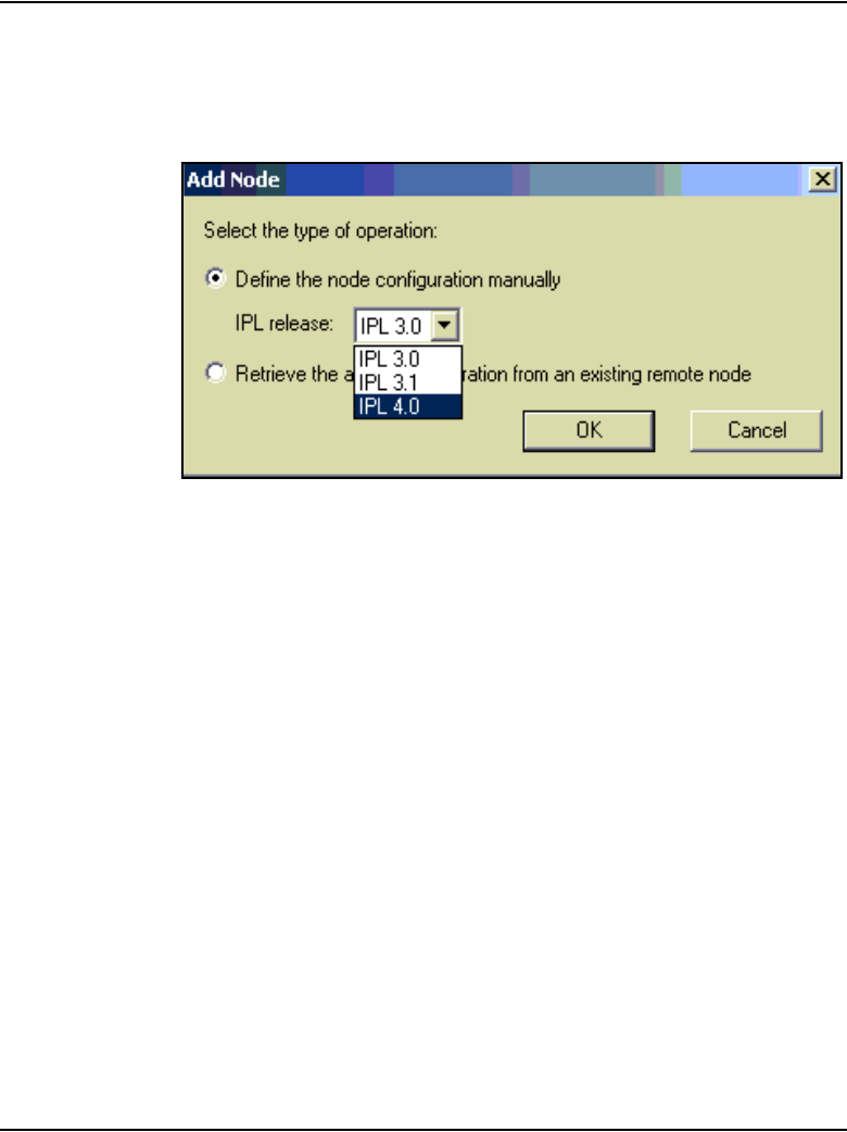
Configuration of IP Telephony nodes using OTM 2.2 Page 465 of 910
IP Line Description, Installation and Maintenance
4Ensure the “Define node configuration manually” radio button is selected.
Select the IP Line software release being installed. Click OK.
Figure 146
Add Node
The New Node window opens. See Figure 147 on page 466.

Page 466 of 910 Configuration of IP Telephony nodes using OTM 2.2
553-3001-365 Standard 4.00 August 2005
Figure 147
New Node – General tab
5On the General tab, under Node Location:
a. From the drop-down lists, select an OTM site, OTM system, and
Customer number.
Configuration of IP Telephony nodes using OTM 2.2 Page 467 of 910
IP Line Description, Installation and Maintenance
b. Type in a Node number (one to four digits).
The Node Number field in the tab corresponds to the Node ID field in
the IP Phone configuration. When defining the node number,
determine if the Enhanced Redundancy for IP Line Nodes
functionality is required (see “Enhanced Redundancy for IP Line
nodes” on page 251). If it is required, factor the requirement into the
node number assignment process.
c. Write down the node number, which is used in the IP Phone
configuration.
6Under Network Connections:
a. Voice LAN Node IP: Enter the Voice LAN (TLAN) Node IP address
in dotted decimal format. Press the space bar to move between each
decimal point. The Voice LAN Node IP address is on the TLAN
subnet. The Node IP address is the IP address used by the IP
Phones to communicate with the Voice Gateway Media Cards on the
CAUTION
The Voice Gateway Media Cards identify themselves
with a node using the node number. If there are multiple
IP Telephony nodes sharing the same TLAN, each node
must have a unique ID. Each system on the TLAN must
have a unique node ID assigned to the Voice Gateway
Media Cards on the system.

Page 468 of 910 Configuration of IP Telephony nodes using OTM 2.2
553-3001-365 Standard 4.00 August 2005
TLAN. If a Voice Gateway Media Card becomes the primary (Leader)
during an election, it assigns itself the Node IP address.
b. Management LAN gateway IP: Enter the Management LAN (ELAN)
gateway IP address in dotted decimal format. This is the IP address
of the gateway of the subnet to which the Voice Gateway Media Card
belongs. This is the IP address of the router interface on the ELAN
subnet, if present. If there is no Management LAN gateway, enter
0.0.0.0.
c. Management LAN subnet mask: Enter the Management LAN
(ELAN) network interface subnet mask address in dotted decimal
format. This is the subnet mask that is used, along with the ELAN
network interface IP address, to identify the subnet to which the
Voice Gateway Media Card belongs.
d. Voice LAN subnet mask: Enter the Voice LAN (TLAN) subnet mask
address in dotted decimal format. This is the subnet mask used along
with the TLAN IP address, to identify the subnet to which the Voice
Gateway Media Card belongs.
7Click the Configuration tab and continue with Procedure 52 on
page 469.
End of Procedure
CAUTION
Nortel recommends that the TLAN network interface IP
address of the Voice Gateway Media Card(s) and the
TLAN Node IP address not be the same IP address; that
is, each IP address should be unique. (Note: the TLAN
network interface IP address of the Voice Gateway
Media Card(s) is configured on the Configuration tab.)
If a card’s TLAN network interface IP address and the
Node IP address are the same, then it is necessary to
reboot the Voice Gateway Media Card every time there
is a temporary loss of ELAN or TLAN subnet
connectivity.

Configuration of IP Telephony nodes using OTM 2.2 Page 469 of 910
IP Line Description, Installation and Maintenance
Configure the card properties of the Voice Gateway
Media Card
If the IP Network Administrator provides IP addresses and subnet masks in
CIDR format, for example, “10.1.1.10/24”, convert the subnet mask to dotted
decimal format. See Appendix E on page 901.
Note 1: On the Configuration tab, cards can be added, changed, or
deleted in the node one at a time.
Note 2: The Leader 0 card cannot be deleted in the Configuration tab.
It is necessary to delete the node to delete Leader 0.
Follow the steps in Procedure 52 on page 469 to configure card properties for
the Voice Gateway Media Card.
Procedure 52
Configuring card properties for the Voice Gateway Media Card
1Click the Configuration tab in the New Node window.
See Figure 148 on page 470.
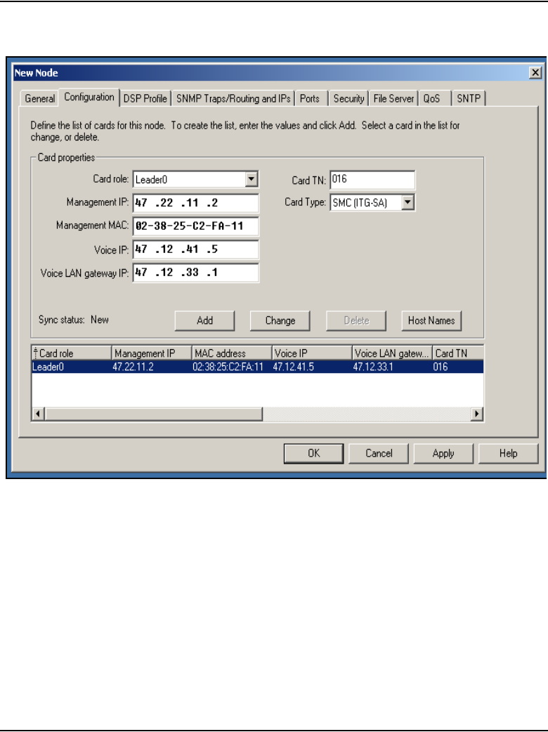
Page 470 of 910 Configuration of IP Telephony nodes using OTM 2.2
553-3001-365 Standard 4.00 August 2005
Figure 148
New Node – Configuration tab

Configuration of IP Telephony nodes using OTM 2.2 Page 471 of 910
IP Line Description, Installation and Maintenance
2Enter the Card Properties data for the Leader 0 and Follower cards as
follows:
a. Card role: Assign the Card role of Leader 0, to the first card
configured. For the second card configured, assign the role of
Leader 1. For all remaining cards, assign the role of Follower.
Note: When adding cards for a node that resides on a CS 1000S system
for the purpose of retrieving OM reports, always assign the Signaling
Server to be the Leader 0 card. A backup Signaling Server, if present, is
assigned to be the Leader 1 card and all the Voice Gateway Media Cards
in the node are assigned to be Follower cards. If no Backup Signaling
Server is present, assign one of the Voice Gateway Media Cards in the
node to be the Leader 1 card.
b. Management IP: This is the ELAN network interface IP address for
the Voice Gateway Media Card. OTM 2.2 and Meridian 1/CS 1000M
use this address to communicate with the card.
Note: Ensure that the ELAN network interface IP address of the Voice
Gateway Media Card is not the same IP address as the Call Processor
ELAN network interface IP address that is configured on the Ports tab.
Each IP address must be unique.
c. Management MAC: This is the motherboard Ethernet address from
the “Voice Gateway Media Card installation summary sheet” on
page 307.
d. Voice IP: This is the TLAN network interface IP address for the card.
e. Voice LAN gateway IP: This is the IP address of the router interface
on the TLAN.
CAUTION
Nortel recommends that the TLAN network interface IP
address of the Voice Gateway Media Card(s) and the
TLAN Node IP address not be the same IP address; that
is, each IP address should be unique. (Note: the TLAN
Node IP address is configured on the General tab.)
If a card’s TLAN network interface IP address and the
Node IP address are the same, then it is necessary to
reboot the Voice Gateway Media Card every time there
is a temporary loss of ELAN or TLAN subnet
connectivity.

Page 472 of 910 Configuration of IP Telephony nodes using OTM 2.2
553-3001-365 Standard 4.00 August 2005
f. Card TN: For Large Systems, enter Card TN (l s c) information. For
Small Systems and CS 1000S systems, enter two zeros followed by
the card slot number (1-50); for example, 0 0 49. The card TN format
is determined by the system type that is configured in the OTM
Navigator. Ensure the correct system type is entered in the OTM
Navigator before adding the node.
g. Card Type: Choose either Pentium or StrongArm. Select Pentium if
using a ITG-P 24-port line card (dual-slot card). Select StrongArm if
using a Media Card (single-slot card).
h. Click Add. The card role and address information appears in a
working list at the bottom of the New Node window.
i. Repeat the above steps for each card that is being added to the
node.
3Click Apply to add the card(s) to the Node.
Note: When Apply is clicked, the title of the window changes from New
Node to Node Properties.
End of Procedure
Configure DSP profile data
In OTM 2.2, the DSP Profile tab and its two sub-tabs (DSP Options and
Codec Options) are used to configure DSP profile data.
Follow the steps in Procedure 53 to configure DSP profile data.
Procedure 53
Configuring DSP profile data using OTM
1Click the DSP Profile tab.
The DSP Options sub-tab opens. See Figure 149 on page 473.
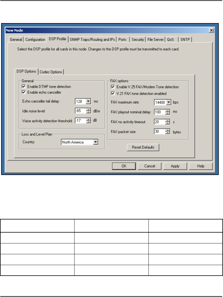
Configuration of IP Telephony nodes using OTM 2.2 Page 473 of 910
IP Line Description, Installation and Maintenance
Figure 149
New Node – DSP Profile tab
Table 71 lists the configurable DSP parameters, the range of the values,
and the default values.
Table 71
DSP parameters (Part 1 of 2)
Parameter Range Default value
Enable DTMF tone detection checked or unchecked checked
Enable echo canceller checked or unchecked checked
Echo canceller tail delay 64 or 128 ms 128 ms
Idle noise level –327 to +327 dB –65

Page 474 of 910 Configuration of IP Telephony nodes using OTM 2.2
553-3001-365 Standard 4.00 August 2005
2Click the Codec Options sub-tab. See Figure 150 on page 476.
Up to four codecs can be selected.
Note: The T.38 Fax and G.711 Clear Channel Fax codecs are not
counted in this limit.
The G.711 codec type is mandatory and is automatically selected.
Voice activity detection
threshold
–20 to +10 dB –17 dB
Enable V.25 FAX/Modem
tone detection
checked or unchecked checked
Enable V.21 FAX tone
detection
checked or unchecked checked
FAX maximum rate 2400, 4800, 7200, 9600,
12000, 14400 bps
14400 bps
FAX playout nominal delay 0 – 300 ms 100 ms
FAX no activity timeout 10 – 32000 seconds 20 seconds
FAX packet size 20 – 48 bytes 30 bytes
Recommendation
Nortel recommends that the system be configured with both G.711 and
G.729A if there is a possibility that IP Softphone 2050 could be
configured with the “I use a modem to connect to the network” check box
checked. If the node does not have G.729A and/or G.723 configured, IP
Softphone 2050 users with that checkbox selected will have calls
blocked. (Note: This does not apply to the MVC 2050.)
For more information, refer to IP Phones: Description, Installation, and
Operation (553-3001-368) in the “Select Sound Devices tab” section.
Table 71
DSP parameters (Part 2 of 2)
Parameter Range Default value

Configuration of IP Telephony nodes using OTM 2.2 Page 475 of 910
IP Line Description, Installation and Maintenance
3Under Codec Options, the following parameters are user-configurable
on a per-codec basis:
Leave the values at their default settings unless directed to change them
as follows or by Nortel Field Support.
a. Law type: The law type is applicable to G.711 only. The default is
mu-law.
b. Voice Activity Detection: The default is VAD disabled.
The VAD value is stored in the Config.ini file under the entry
VadEnabled=
VAD is not supported for G.711.
c. Voice payload size: The default is the maximum supported. This
parameter is not configurable for the following:
• G.723.1
•T.38 Fax
• G.711 Clear Channel Fax
The payload size is stored in the Config.ini file under the entry
VxPayload=
d. Voice playout nominal delay (nominal jitter buffer)
Voice playout maximum delay (maximum jitter buffer)
The default values and the range of allowed values are displayed in
the drop-down lists.
4Click OK.

Page 476 of 910 Configuration of IP Telephony nodes using OTM 2.2
553-3001-365 Standard 4.00 August 2005
Figure 150
New Node – DSP Profile tab - Codec Options sub-tab with G.729 AB Codec selected
Note: If there are multiple nodes on a system and the same codec is
selected on more than one node, ensure that each node has the same
voice payload size configured for the codec.
End of Procedure
Configure SNMP traps and ELAN gateway routing table
Follow the steps in Procedure 54 to configure SNMP traps and the ELAN
gateway routing table.
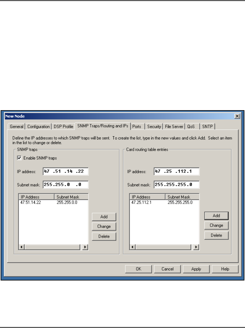
Configuration of IP Telephony nodes using OTM 2.2 Page 477 of 910
IP Line Description, Installation and Maintenance
Procedure 54
Configuring SNMP traps and ELAN GW Routing table
1Click the SNMP Traps/Routing and IPs tab in the New Node window.
See Figure 151 on page 477.
IP addresses that are added in this tab create special card routing tables
that direct packets out the ELAN network interface and ELAN gateway.
Exercise caution when adding entries since the entry could result in
one-way voice transmission if a change results in voice packets being
streamed out the ELAN network interface instead of the TLAN network
interface.
Figure 151
New Node – SNMP Traps/Routing and IPs tab

Page 478 of 910 Configuration of IP Telephony nodes using OTM 2.2
553-3001-365 Standard 4.00 August 2005
2On the left side of the window, under SNMP traps:
a. Enable SNMP traps: Check the Enable SNMP traps checkbox, if
configuring one or more SNMP management IP addresses to receive
SNMP traps from cards in the IP Telephony node.
b. IP address: If SNMP traps are enabled, this is the IP address of the
destination where the SNMP traps are sent.
c. Subnet mask: If SNMP traps are enabled, this is the subnet mask of
the destination where SNMP traps are sent.
To add a trap destination IP address, enter the IP address in the
SNMP IP address fields, and click Add. Add SNMP Manager IP
addresses for the following:
— local or remote OTM server
— PPP IP address configured in the router on the ELAN subnet for
the remote support OTM PC
— SNMP manager for remote alarm monitoring
Note 1: Up to eight SNMP trap destinations can be defined.
Note 2: A net route or host route through the ELAN gateway is added to
the Voice Gateway Media Cards IP Routing Table for each SNMP
management address that is added to the SNMP traps list.
3Click Apply.
4To transmit the information to the node, from the menu select
Configuration > Synchronize > Transmit.
5On the SNMP Traps/Routing and IPs tab on the right side of the window,
under Card routing table entries, enter the IP address and Subnet
mask for any host that is not on the ELAN subnet but requires access to
the Voice Gateway Media Card across the ELAN subnet. A Telnet
session for maintenance from a remote PC is an example of when this
would be needed. The address of the remote PC would be added in the
Route list.
Configuration of IP Telephony nodes using OTM 2.2 Page 479 of 910
IP Line Description, Installation and Maintenance
The default route on the card causes packets for unknown subnets to be
sent out on the TLAN network interface. Packets from an external host
arrive on the ELAN network interface and responses are sent on the
TLAN network interface. This can cause one-way communication if the
TLAN subnet is not routed to the ELAN subnet. It is necessary to add an
entry in the Route list, to correct the routing so that response packets are
sent on the ELAN network interface. Each entry creates a route entry in
the card's route table that directs packets to the ELAN network interface.
See Figure 152 on page 480.
6To add a net route or host route, type the IP address and subnet mask in
the entry field of the card routing table, and click Add.
7Click Apply.
CAUTION
Use caution when assigning card routing table entries.
Do not include the IP address of an IP Phone. Otherwise,
voice traffic to this IP Phone is incorrectly routed through
the ELAN network interface and ELAN gateway. To
avoid including the wrong IP address, Nortel
recommends that Host IDs be defined for the card
routing table entries.
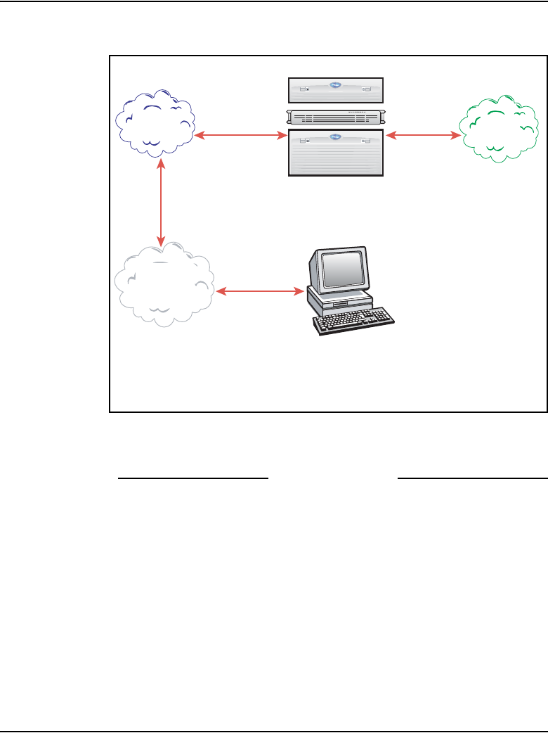
Page 480 of 910 Configuration of IP Telephony nodes using OTM 2.2
553-3001-365 Standard 4.00 August 2005
Figure 152
Specifying additional ELAN subnet routes
8Click OK to exit the window.
End of Procedure
Configure node synchronization with the Call Server
The SNMP MIB II parameters are configured as a node property in the group
box “SNMP parameters” on the New Node - General tab. See Figure 153 on
page 481.
The check box enables/disables synchronization of the SNMP parameters
with the Call Server. The default value is selected. During Update System
Data, the SNMP parameters are propagated to all existing IP nodes that have
the “Synchronize with PBX system” option selected. Status of the node is set
to changed (CHG).
In this diagram, an additional ELAN route is required to
reach the management workstation, which is accessible
throu
g
h the ELAN network interface but is not on the ELAN subnet.
Management
Workstation
Meridian 1 or CS 1000
TLAN route /
default route
ELAN route +
additional routes
ELAN
subnet
TLAN
subnet
Some
other
LAN
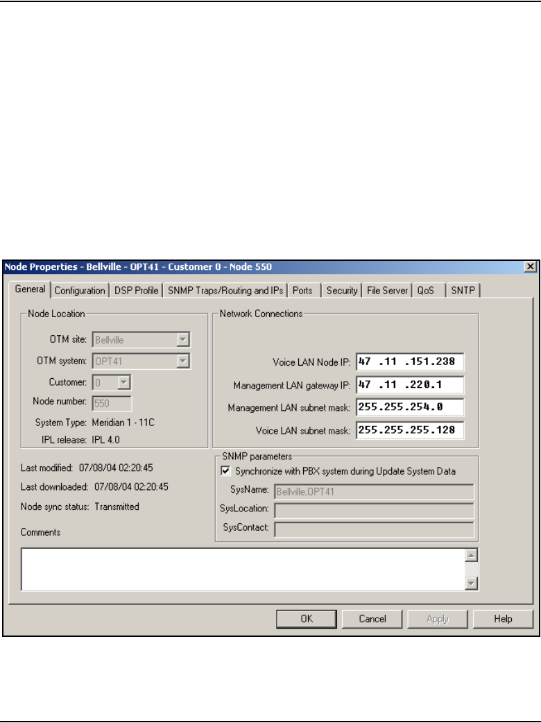
Configuration of IP Telephony nodes using OTM 2.2 Page 481 of 910
IP Line Description, Installation and Maintenance
When the check box is selected, the fields are set to read-only. When the
check box is not selected, the fields are set to read/write, and synchronization
does not occur for that node.
Follow the steps in Procedure 55 to configure node synchronization with the
Call Server.
Procedure 55
Configuring node synchronization with the Call Server
1Click the Node Properties - General tab for the desired node. See
Figure 153.
Figure 153
SNMP parameters

Page 482 of 910 Configuration of IP Telephony nodes using OTM 2.2
553-3001-365 Standard 4.00 August 2005
2Check the Synchronize with PBX system during Update System Data
check box.
3Click Apply.
4Click OK to exit the window.
End of Procedure
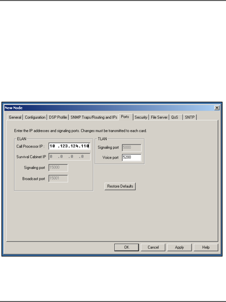
Configuration of IP Telephony nodes using OTM 2.2 Page 483 of 910
IP Line Description, Installation and Maintenance
Configure the Call Server ELAN network interface IP address
and the TLAN voice port
Follow the steps in Procedure 56 to configure the Call Server network
interface IP address (Active ELNK) and the TLAN voice port.
Procedure 56
Configuring the Call Server ELAN network interface IP address (Active
ELNK) and the TLAN voice port
1Click the Ports tab. See Figure 154.
Figure 154
New Node – Ports tab

Page 484 of 910 Configuration of IP Telephony nodes using OTM 2.2
553-3001-365 Standard 4.00 August 2005
2Enter the following ELAN network interface settings:
a. Call Processor IP: Enter the Call Processor ELAN network interface
IP Address (Active ELNK).
Note 1: Ensure that the Call Processor ELAN network interface IP
address that is configured on the Ports tab is not the same IP address as
the ELAN network interface IP address of the Voice Gateway Media Card.
Each IP address must be unique.
Note 2: The Call Processor ELAN network interface IP address must
correspond to the Active ELNK IP address configured in LD 117. It must
be in the same subnet as the ELAN subnet for the IP Telephony node.
b. Survival Cabinet IP: If applicable, enter the Survivable Cabinet
ELAN network interface IP address (Active ELNK). This is the IP
address that is configured for survivability. The survivable Cabinet IP
is enabled only for Small Systems and CS 1000S systems.
Note: For Small Systems or CS 1000S, this field is disabled unless at
least one cabinet has been defined as a survival cabinet of the main
system in OTM Navigator. There is only one survival cabinet IP address
for each node. The survival cabinet is equipped with sufficient trunk cards
and Voice Gateway Media Cards. In case of Call Server equipment
failure, it provides a large degree of survivability for IP Phone users.
c. Signaling port: The default value is 15000. This field is read-only.
d. Broadcast port: The default value is 15001. This field is read-only.
3Enter the following TLAN settings:
a. Signaling port:
b. Voice port: Change the Voice port only as instructed by the IP
network administrator to improve QoS for the IP Phones. For
example, if RTP Header compression is used to reduce voice
bandwidth on narrow-band WAN links, then TLAN voice port range
must be set to 16384 or higher. The exact range will be provided by
the system administrator.
Note: The TLAN Voice port range is 1024 to 65535. The default Voice
ports are 5200-5295.

Configuration of IP Telephony nodes using OTM 2.2 Page 485 of 910
IP Line Description, Installation and Maintenance
Note 3: The TLAN Signaling occurs on UDP ports 7300, 4100, 5100, and
5000.
4Click Apply.
End of Procedure
Configure security for SNMP access
Change the SNMP community names to control access to the IP Telephony
node. OTM uses the community names to refresh the Voice Gateway Media
Card status, and to control the transmitting and retrieving of configuration
data files for database synchronization.
Use OTM to configure SNMP on the Meridian 1 Call Server and Voice
Gateway Media Cards.
Configure SNMP access and community name strings
Follow the steps in Procedure 57 on page 486 to configure SNMP access for
the system.
CAUTION
Do not set the Voice port to a value that is already used
for signaling (4100, 5000, 5100, 7300).
The Voice port defines the first port in a range spanning
the gateway channels on the card; this means a Voice
port value of 5200 reserves the following:
• ports 5200-5263 on the Media Card 32-port line card
• 5200-5215 on the Media Card 8-port line card
• 5200-5247 on the ITG-P 24-port line card.
If this value is changed from the default, confirm the
selected Voice port value does not range into one of the
reserved signaling port values.

Page 486 of 910 Configuration of IP Telephony nodes using OTM 2.2
553-3001-365 Standard 4.00 August 2005
Procedure 57
Configuring SNMP access and community name strings
1Click the General tab on System properties.
See Figure 155.
Figure 155
System properties - General tab
2Enter the System Name data.
3Select the Configure SNMP parameters using OTM data in this tab
during Update System Data check box.
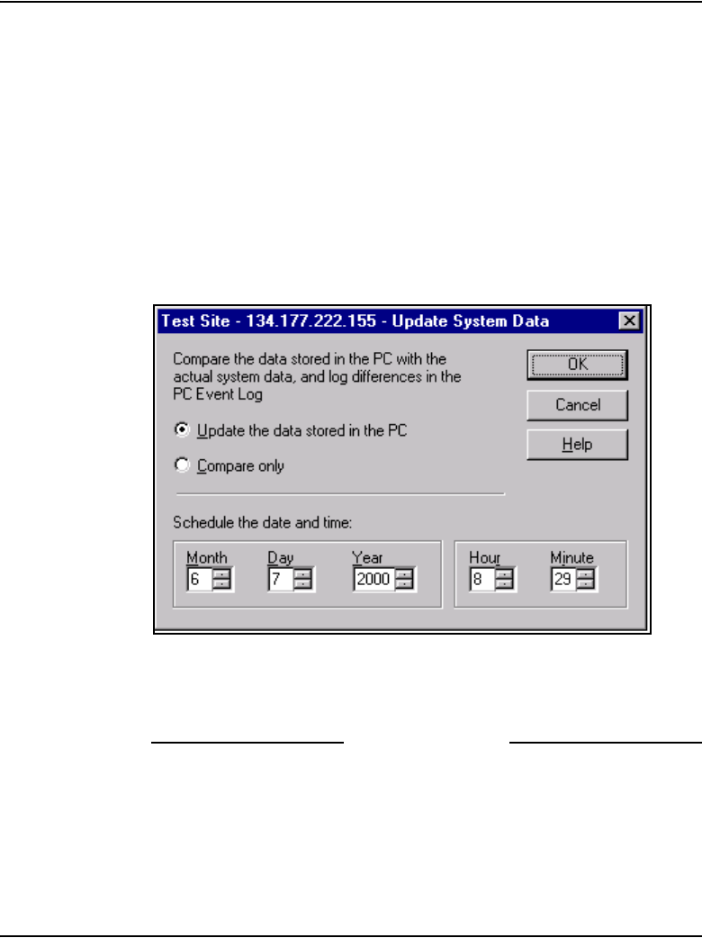
Configuration of IP Telephony nodes using OTM 2.2 Page 487 of 910
IP Line Description, Installation and Maintenance
4Change the default System Mgmt Read, System Mgmt Read/Write,
Admin 1, Admin 2, and Admin 3 community names.
5Enter the System Location and Contact Information data.
6Click Apply.
7Click OK to exit the window.
8To update the system data, from the System Window menu bar, click
File > Update System Data.
The Update System Data dialog box opens. See Figure 156.
Figure 156
Update System Data dialog box
9Select Update the data stored in the PC.
10 Click OK to update the system data.
End of Procedure
SNMP community name strings (passwords) are required to access the Voice
Gateway Media Card. The community name strings are not configured on the
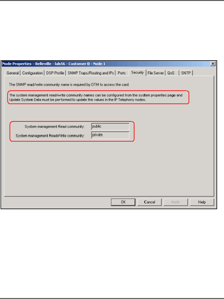
Page 488 of 910 Configuration of IP Telephony nodes using OTM 2.2
553-3001-365 Standard 4.00 August 2005
Security tab. They are displayed as read-only for information purposes. See
Figure 157.
Community name strings are configured on the System Properties - General
tab. See Procedure 57 on page 486.
Figure 157
Node Properties – Security tab
Configure SNMP trap destinations for an IP Telephony node
Follow the steps in Procedure 58 on page 489 to use OTM to configure
SNMP trap destinations for an IP Telephony node.
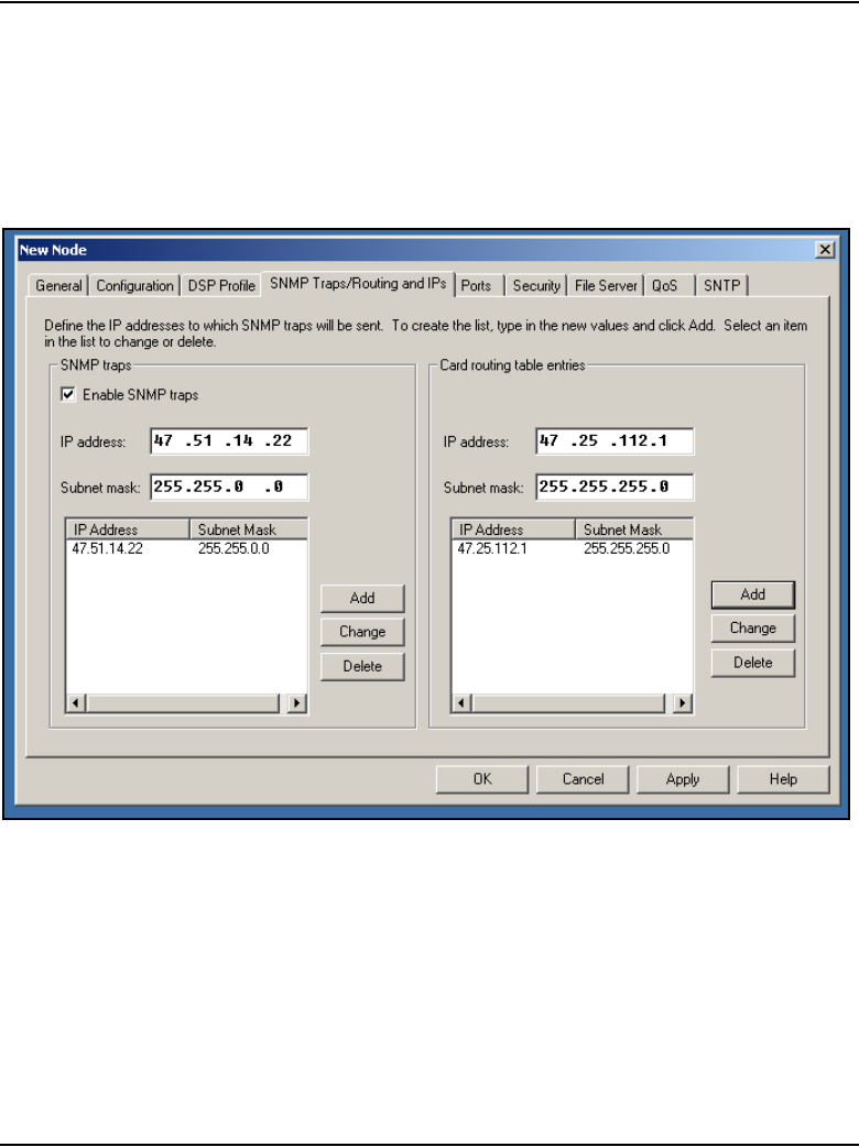
Configuration of IP Telephony nodes using OTM 2.2 Page 489 of 910
IP Line Description, Installation and Maintenance
Procedure 58
Configuring SNMP trap destinations for an IP Telephony node
1Click the SNMP Traps/Routing and IPs tab in the Node Properties
window. See Figure 151.
Figure 158
Node Properties – SNMP Traps/Routing and IPs tab
2On the left side of the window, under SNMP traps:
a. Enable SNMP traps: Select the Enable SNMP traps check box, if
configuring one or more destination SNMP management IP
addresses to receive SNMP traps from cards in the IP Telephony
node.
b. IP address: If SNMP traps are enabled, this is the IP address of the
destination where the SNMP traps are sent.

Page 490 of 910 Configuration of IP Telephony nodes using OTM 2.2
553-3001-365 Standard 4.00 August 2005
c. Subnet mask: The subnet mask for the IP address of the trap
destination must always be configured as 255.255.25.255.
d. To add a trap destination IP address, enter the IP address and
subnet mask (if applicable) in the SNMP IP address field, and click
Add.
Add trap destination IP addresses for the following:
— local or remote OTM server
— PPP IP address configured in the router on the ELAN subnet for
the remote support OTM PC
— SNMP manager for remote alarm monitoring
Note: Up to eight SNMP trap destinations can be defined.
3Click Apply.
4Click OK to exit the window.
5To transmit the information to the node, from the menu select
Configuration > Synchronize > Transmit.
End of Procedure
Note: If the community names are forgotten, connect a TTY to the
Voice Gateway Media Card maintenance port. Restart the card. The card
displays the community name on the TTY during start-up.
WARNING
Do not enter the actual value of the subnet mask on the
interface of the SNMP trap destination. Doing so can
cause misrouting of RTP media and signaling, leading to
no speech path between the IP Phones and the Voice
Gateway Media Cards or failure of the IP Phones to
register with the LTPS.

Configuration of IP Telephony nodes using OTM 2.2 Page 491 of 910
IP Line Description, Installation and Maintenance
Configure file server access
With the addition of new IP Phones, there are also additional firmware files
for the IP Phones. The Voice Gateway Media Card has limited space to store
the files for all the IP Phones on the card. Instead, a file server can be used to
store the IP Phone firmware files.
The Phase I IP Phone 2002 firmware filename is 0603Bnn.BIN where
Bnn = firmware version 1.nn. The Phase I IP Phone 2004 firmware filename
is 0602Bnn.BIN where Bnn = F/W version 1.nn. The Phase II IP Phone 2001,
IP Phone 2002, and IP Phone 2004 firmware filename is 0603Dnn.BIN where
Dnn = F/W version 3.nn.
External file server option
If the external file server option is used in OTM 2.2 for firmware distribution
with a node, the following files must be renamed before being placed on the
server.
• 0602Bnn.BIN file renamed to X00.fw
• 0603Bnn.BIN file renamed to X01.fw
• 0604Dnn.BIN renamed to X02.fw
To configure the file server, follow the steps in Procedure 59 on page 492.
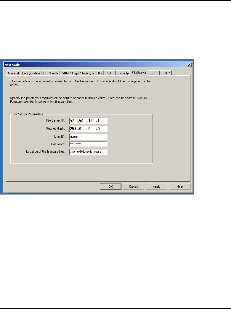
Page 492 of 910 Configuration of IP Telephony nodes using OTM 2.2
553-3001-365 Standard 4.00 August 2005
Procedure 59
Configuring access to the File Server
1Click the File Server tab. See Figure 159.
Figure 159
New Node – File Server tab
2Under File Server Parameters, specify the parameters needed to
connect to the file server:
a. File Server IP: Enter the IP address of the file server.
b. Subnet Mask: Enter the subnet mask of the file server.
c. User ID: Enter the user ID that is required to access the file server.
d. Password: Enter the password that is required to access the file
server.
e. Location of the firmware files: Enter the path for the location of the
firmware files. See page 242 for the default location of firmware files
for the system.
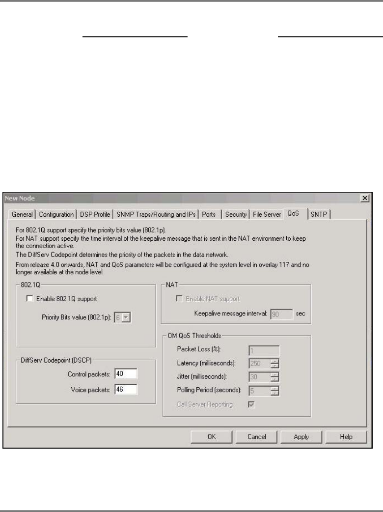
Configuration of IP Telephony nodes using OTM 2.2 Page 493 of 910
IP Line Description, Installation and Maintenance
3Click Apply.
End of Procedure
Configure QoS
Configure QoS by enabling 802.1Q and NAT support, configuring DiffServ
CodePoint (DSCP) settings, and configuring OM QoS thresholds.
Procedure 60
Enabling 802.1Q and configuring DSCP settings
1Click the QoS tab. See Figure 160.
Figure 160
New Node – QoS tab

Page 494 of 910 Configuration of IP Telephony nodes using OTM 2.2
553-3001-365 Standard 4.00 August 2005
2802.1Q enables virtual LANs (VLANs) to be defined within a single LAN.
This improves bandwidth management and limits the impact of broadcast
and multicast messages.
Configure the 802.1Q settings as follows:
a. Enable 802.1Q support: Select the check box to enable 802.1Q
support. By default, 802.1Q support is disabled.
b. Priority Bits value (802.1p): The priority field is a 3-bit value, with a
default value of 6. The range is 0 – 7. A value of 6 is recommended
by Nortel. The p bits within the 802.1Q standard enables packet
prioritization at Layer 2, improving network throughput for
IP Telephony data.
Note: These values are applied to all Voice Gateway Media Cards in the
node.
3Under DiffServ Codepoint, modify the DSCP Control and Voice values
only as directed by the IP network administrator.
The recommended configuration values are:
a. Control packets: A value of 40 – Class Selector 5 (CS5). This sets
the priority of the signaling messaging.
b. Voice packets: A value of 46 Control DSCP – Expedited Forwarding
(EF).
The DSCP determines the priorities of the management and voice
packets in the IP Line network. The range for both management and
voice packet DSCP is 0 – 63 inclusive.
The DSCP value can be configured, if required, to obtain better QoS
over the IP data network (LAN/WAN).
The value entered depends on the policy in the customer’s data
network.
Note: Do not change DSCP from the default values unless instructed.
4Click Apply and then click OK.
Note: As described on the QoS tab, NAT and QoS parameters are no
longer configured here. Therefore, those areas are grayed out.
End of Procedure
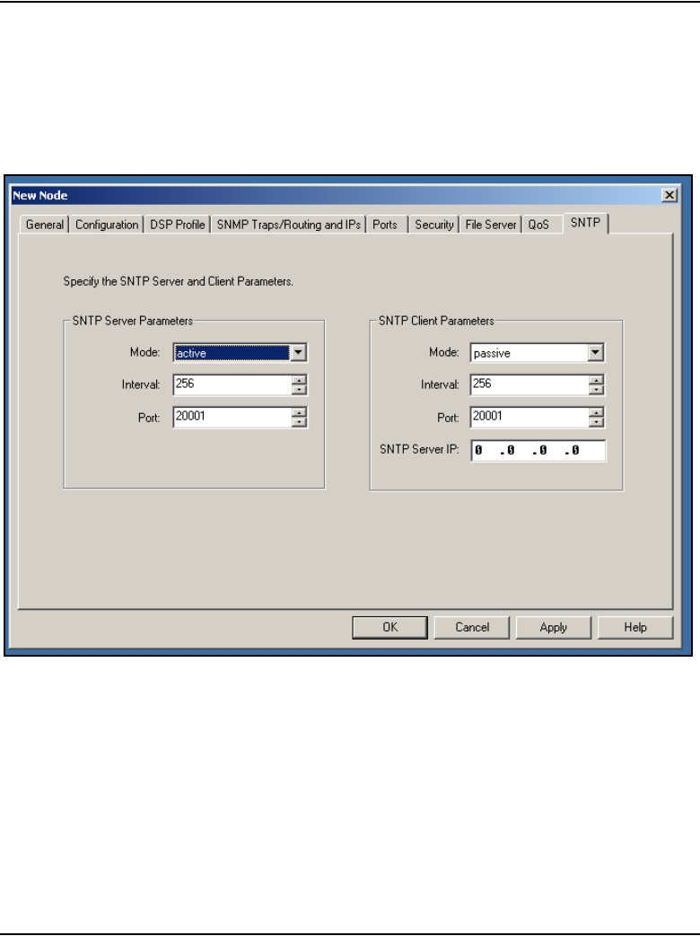
Configuration of IP Telephony nodes using OTM 2.2 Page 495 of 910
IP Line Description, Installation and Maintenance
Configure SNTP
Simple Network Time Protocol (SNTP) can be configured for an SNTP
Server and SNTP Client. See Figure 161.
Figure 161
SNTP configuration tab
SNTP Server parameters
The following are the parameters for the SNTP Server:
•Mode: Can be configured as active or passive. The default is active.
•Intervals (seconds): The range is 0 –2147483646. The default is 256.
•Port: The range is 0 – 99999. The default is 20000 + the Node number.

Page 496 of 910 Configuration of IP Telephony nodes using OTM 2.2
553-3001-365 Standard 4.00 August 2005
Note: The Node number is the same value as the value stored in the
Node number field in the main IP Telephony application window.
SNTP Client parameters
The following are the parameters for the SNTP Client:
•Mode: Can be configured as active or passive. The default is passive.
•Intervals (seconds): The range is 0 –2147483646. The default is 256.
•Port: The range is 0 – 99999. The default is 20000 + the Node number.
• SNTP Server IP address. The default is 0.0.0.0.
Note: The Node number is the same value as the value stored in the
Node number field in the main IP Telephony application window.
Transmit node configuration from OTM 2.2
to the Voice Gateway Media Cards
Before transmitting the node configuration to the Voice Gateway Media
Cards, ensure the following:
• Voice Gateway Media Cards and cables have been installed.
• ELAN and TLAN network interfaces of all cards are connected with
access to the IP network.
• IP Line 4.5 data has been configured in OTM 2.2.
• OTM 2.2 server is connected to the local ELAN subnet or to a remote
subnet with IP router access to the ELAN and TLAN subnets.
The IP Telephony node and card properties are configured using OTM 2.2’s
IP Line 4.5 application. The configuration data is converted to text files by
OTM 2.2 and is then transmitted to the Voice Gateway Media Cards.
The process consists of the following steps:
1Set the Leader 0 IP address from a TTY connected to the local RS-232
maintenance port. See Procedure 61 on page 497.
2Reboot Leader 0.

Configuration of IP Telephony nodes using OTM 2.2 Page 497 of 910
IP Line Description, Installation and Maintenance
3Transmit the node and card properties from the OTM IP Line 4.5
application to Leader 0. See Procedure 62 on page 499.
4Reboot Leader 0.
5Transmit card properties to all cards in the node. See Procedure 63 on
page 501.
Set the Leader 0 IP address
Follow the steps in Procedure 61 to configure the IP address of a factory-new
Leader 0 Voice Gateway Media Card.
If the card is being re-used from an existing installation, enter the commands
NVRClear, followed by clearLeader, at the card’s CLI.
Procedure 61
Configuring the Leader 0 IP address
1Access the IPL> CLI by connecting the COM port of an OTM 2.2 PC to
the RS-232 serial maintenance port on the faceplate of the Leader 0
Voice Gateway Media Card. Use an NTAG81CA PC Maintenance cable.
If required, use an NTAG81BA Maintenance Extender cable between the
PC Maintenance cable and the OTM PC.
Alternatively, connect the NTAG81BA Maintenance Extender cable to the
female DB-9 connector of the NTMF94EA ELAN, TLAN RS-232 Ports
cable for a more permanent connection to the Voice Gateway Media Card
serial maintenance port.
Note: Never connect two terminals to the faceplate and I/O panel
breakout cable serial maintenance port connectors at the same time.
2Use the following communication parameters for the TTY terminal
emulation on the OTM PC:
• 9600 baud
• 8 bits
• no parity
• one stop bit
3Observe the Leader 0 card faceplate maintenance display window.

Page 498 of 910 Configuration of IP Telephony nodes using OTM 2.2
553-3001-365 Standard 4.00 August 2005
When the display reads “T:20”, it begins to send BootP requests on the
ELAN subnet. A series of dots is printed on the TTY.
If the card does not display “T20”, or has stopped printing the series of
dots on the TTY, reboot the card and wait for “T20” to be displayed.
4Type +++ to escape from the BootP request.
5At the Login prompt, enter the default user ID and password of itgadmin
and itgadmin to access the IPL> CLI:
itg Login: itgadmin
Password: itgadmin
6When the maintenance window displays “T:21”, at the IPL> prompt, enter:
setLeader “xx.xx.xx.xx”,“yy.yy.yy.yy”,“zz.zz.zz.zz”
The three parameters must each be enclosed in double quotation marks.
Ensure that there is a space after the command and before the first
parameter. Put commas and no spaces between the following
parameters:
“xx.xx.xx.xx”=IP address.
Enter the same IP address that was entered in the Management LAN
IP field for Leader 0 in the Configuration tab of the Node Properties
window.
“yy.yy.yy.yy”=Gateway IP address.
Enter the same address that was entered in the Management LAN
gateway IP field in the General tab of the Node Properties window.
If there is none, enter the following: “0.0.0.0”
“zz.zz.zz.zz”=Management LAN subnet mask.
Enter the same address that was entered in the Management LAN
subnet mask field in the General tab of the Node Properties window.
Note: This step assumes that the new IP Telephony node has already
been configured in OTM 2.2.
7Reboot the Leader 0 Voice Gateway Media Card. At the IPL> prompt,
enter: cardReset, or press the Reset button on the faceplate of the
Leader 0 Voice Gateway Media Card.
8Check the maintenance display for T:22 to confirm a successful reboot.

Configuration of IP Telephony nodes using OTM 2.2 Page 499 of 910
IP Line Description, Installation and Maintenance
9From the OTM IP Telephony Gateway - IP Line 4.5 application, select
View > Refresh to show the card status. Otherwise, verify LAN
connections and IP configuration.
End of Procedure
Transmit node and card properties to Leader 0
To transmit the node and card properties to Leader 0, follow the steps in
Procedure 62.
Procedure 62
Transmitting node and card properties to Leader 0
1Log into LD 32 on the system. Disable the card in order to transmit the
card properties.
2Open OTM. From the OTM Navigator window, click on the Services
folder to expand the menu. Double-click on IP Line 4.5. The IP
Telephony Gateway - IP Line 4.5 window opens.
3From the list of IP Telephony nodes in the upper part of the window, select
the node to which configuration data is to be transmitted.
4Select Configuration > Synchronize > Transmit.
The Transmit Options window appears. See Figure 162 on page 500.
CAUTION
OTM 2.2 does not support transmitting node and/or card
properties to a node (or any of the card within the node)
which resides on a CS 1000 system.
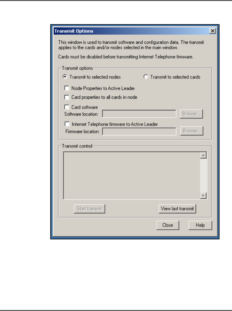
Page 500 of 910 Configuration of IP Telephony nodes using OTM 2.2
553-3001-365 Standard 4.00 August 2005
Figure 162
Transmit Options dialog box
5Use the default setting of Transmit to selected nodes. Select both the
Node Properties to Active Leader and the Card properties to all cards
in the node check boxes.?

Configuration of IP Telephony nodes using OTM 2.2 Page 501 of 910
IP Line Description, Installation and Maintenance
6Click the Start transmit button. Monitor progress in the Transmit control
area. Confirm that the node and card properties are transmitted
successfully to Leader 0.
Note: At this point, it is normal that the card properties fail to transmit to
the other cards in the node, because they have not yet received the IP
address from Leader 0 BootP server.
7When the transmission is complete, click Close.
8Reboot the Leader 0 Voice Gateway Media Card. At the IPL> prompt,
enter cardReset.
Alternatively, push the Reset button on the faceplate of the Voice
Gateway Media Card.
End of Procedure
Transmit card properties to all cards in the node
To transmit the card properties to all the Voice Gateway Media Cards in the
node, follow the steps in Procedure 63.
Procedure 63
Transmitting card properties to all cards in the node
1To verify installation and configuration of the node properties, observe the
displays on the card faceplate.
• After successfully rebooting, the Leader 0 card is now fully
configured with the Node Properties of the node and enters a state of
“active Leader”. The card faceplate display shows Lxxx, where
xxx = the number of IP Phones registered with the LTPS on the
Leader card. L000 means that no IP Phones are registered.
• The Leader 1 card and any Follower cards receive their configuration
from the Leader 0 card. The faceplate display shows Fxxx, where
xxx = the number of IP Phones registered with the LTPS on the
Leader card. F000 means that no IP Phones are registered.
CAUTION
OTM 2.2 does not support transmitting node and/or card
properties to a node (or to any of the cards within the
node) which resides on a CS 1000 system.
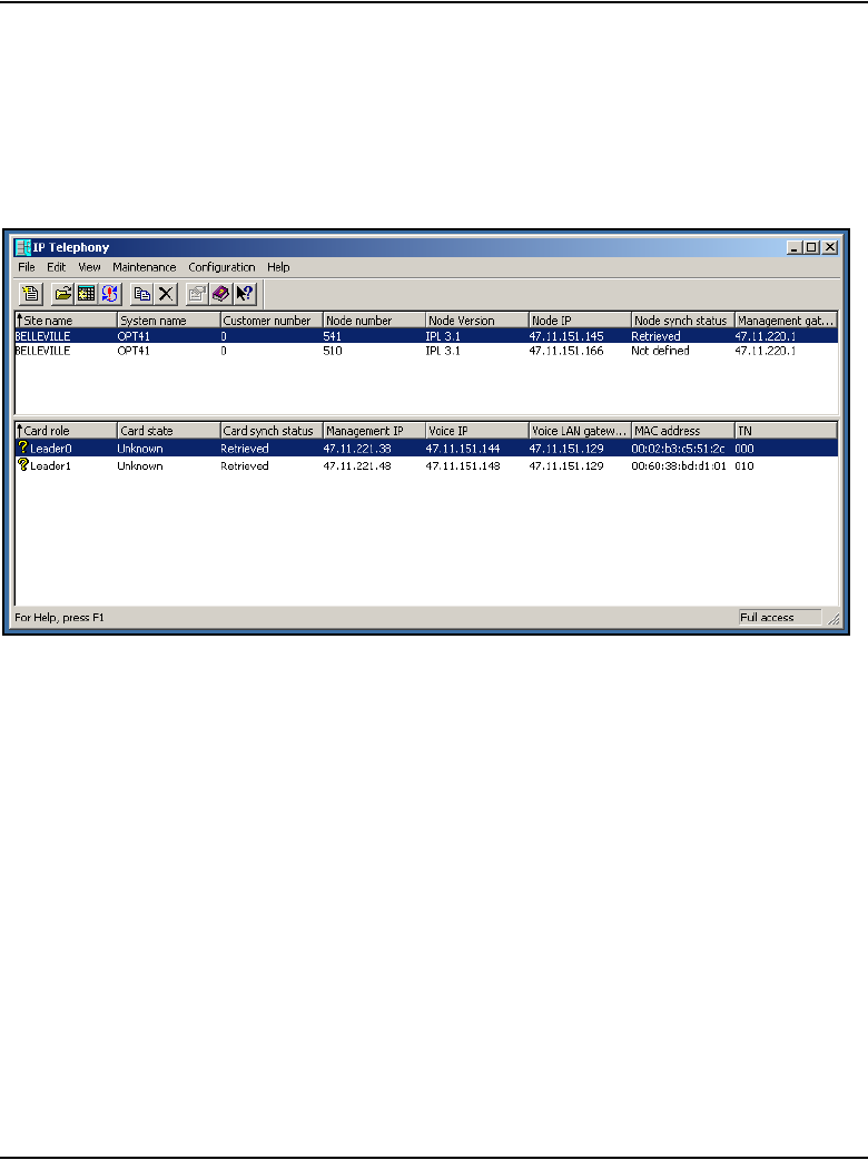
Page 502 of 910 Configuration of IP Telephony nodes using OTM 2.2
553-3001-365 Standard 4.00 August 2005
2In the IP Telephony window, select the new IP Telephony node from the
list in the upper part of the window.
All Voice Gateway Media Cards in the node are displayed in the lower part
of the window. See Figure 163.
Figure 163
IP Telephony window
3Press function key F5 to refresh the card status of all cards in the selected
node.
Alternatively, from the upper menu, select View > Refresh > Selection.
The card status changes from “Unknown” or “Not responding” to
“Disabled”, “Enabled”, and “Unequipped”.
Note: If it is not possible to communicate with the Leader 1 and Follower
cards in the node after transmitting the node and card properties and
rebooting the Leader 0 card, this means that the Voice Gateway Media
Cards are unable to communicate back to the remote OTM PC through
the voice gateway or TLAN router.

Configuration of IP Telephony nodes using OTM 2.2 Page 503 of 910
IP Line Description, Installation and Maintenance
To establish communication with the Leader 1 or Follower cards in the IP
Telephony node, perform the following actions:
a. Verify the TLAN physical and logical connections on all the
non-responsive cards. Ensure the following:
i. cables are plugged securely into the correct TLAN connection
ii. switch is connected to correct TLAN router
iii. remote OTM can communicate with TLAN router
b. If remote OTM 2.2 cannot communicate using the TLAN router,
connect to the Voice Gateway Media Card maintenance port with a
TTY and use the IPL> routeAdd command on each Voice Gateway
Media Card to add a new IP route through the management gateway
that points to the remote OTM PC subnet.
c. Repeat step b if the card is reset before OTM successfully transmits
the card properties (containing the SNMP Manager IP addresses and
the card routing IP addresses).
4When Leader 1 and all Follower cards show a status of disabled, click
Configure > Synchronize > Transmit. When the Transmit window
opens, click the Transmit to selected nodes radio button. Select the
Card properties to all disabled cards check box.
5Click Start transmit. Carefully monitor the progression in the Transmit
Control window. Confirm that the card properties are successfully
transmitted to every Voice Gateway Media Card in the selected node
identified by its TN
6Verify that all Voice Gateway Media Cards in the node have established
a signaling link to the Call Server.
End of Procedure

Page 504 of 910 Configuration of IP Telephony nodes using OTM 2.2
553-3001-365 Standard 4.00 August 2005
Upgrade the Voice Gateway Media Card software
and IP Phone firmware
Before upgrading the software and firmware, determine the version of card
software and IP Phone firmware that is currently installed. Compare the
versions to the latest available versions by accessing the Nortel web site.
Refer to Procedure 64 on page 507 for complete instructions.
When a software or firmware upgrade is required, go to the Nortel web site
to download the appropriate upgrade files. When Internet access is
unavailable from the OTM PC, use a PC with Internet access and transfer the
files to the OTM PC. See Appendix F on page 903.
IP Phone firmware installation and upgrade
The firmware files for the IP Phones are downloaded from OTM 2.2 to the
node Master and saved in a directory on the Master card’s Flash disk. The
node Master then notifies the other cards in the node to retrieve the new files.
When those firmware files are downloaded from OTM, they are compressed
and stored on the /C: drive. File compression reduces the firmware file to less
than 900 Kbytes.
There is no requirement on operations to pre-load the IP Phones with the
correct version of firmware. Except in the case where the UFTP download to
the IP Phone would be blocked (such as when the IP Phone is behind a
firewall that has port 5105 blocked), the IP Phone’s firmware is automatically
upgraded as part of the registration to the LTPS. If the firmware cannot be
upgraded due to firewall restrictions, then upgrade the IP Phone with the
current firmware version before distributing the telephone.
WARNING
Before beginning the upgrade, ensure that a PWD1 user
name and password has been configured on the Call
Server. If there is no PWD1 user name and password,
configure them in LD 17. This is necessary to enable
login to the Voice Gateway Media Cards and Signaling
Server.

Configuration of IP Telephony nodes using OTM 2.2 Page 505 of 910
IP Line Description, Installation and Maintenance
There is one firmware file each for the Phase I IP Phone 2002 and 2004. There
is one firmware file for the Phase II IP Phone 2001, IP Phone 2002, and
IP Phone 2004.
There is limited space on the Voice Gateway Media Card running IP Line 4.5
to store the firmware files. Therefore, the firmware is stored on a file server
or on the Master card’s RAM device.
Note: A firmware download does not occur with IP Phones performing
a Virtual Office login or Branch Office login to a remote system. No
firmware upgrade takes place during a Virtual Office Login or
MG 1000B User registration with the LTPS. The registration is allowed
because the IP Phone firmware version must be 1.33 or later to do a
Virtual Office login or MG 1000B User registration.
The umsUpgradeAll command has no impact on Virtual Office Login
IP Phones. These IP Phones are not reset. If the Virtual Office Login is
on the same Call Server, then the IP Phone firmware is upgraded after the
user logs out. If the Virtual office Login is between different Call
Servers, then the IP Phone just registers back to its home LTPS and
follows the normal firmware rules for regular registration.
When the umsUpgradeAll command is executed, MG 1000B User IP
Phones that are on an active call are flagged. After the IP Phone becomes
idle, the IP Phones are switched by the Call Server back to the
MG 1000B for the firmware upgrade.
Requirements
If a file server is used to store the firmware file, the following items are
required to access the firmware:
• IP address of the file server
• routing table
• file path to the file server
• user name and password required to access the file server
Page 506 of 910 Configuration of IP Telephony nodes using OTM 2.2
553-3001-365 Standard 4.00 August 2005
This information is configured in the OTM 2.2 IP Line 4.5 application. If
using OTM 2.2, this information is configured in the File Server tab of the
Node properties. See Figure 159 on page 492.
The IP Phones use UNIStim File Transfer Protocol (UFTP) to transfer the
firmware; therefore, if the customer’s network has a firewall, port 5105 must
be explicitly opened in the firewall to enable IP Phone firmware downloads
to take place. For more information, refer to “Firmware download using
UNIStim FTP” on page 150.
IP Phone firmware upgrade from a new
Voice Gateway Media Card
Meridian 1
When the Voice Gateway Media Card is received from the factory, the
IP Line 4.5 software is located on the CompactFlash card. Go to the Nortel
web site and download the firmware for the IP Phones to the Leader card. See
Appendix F on page 903.
IMPORTANT!
All IP Phones in a system must use the same version of firmware as is
on the Voice Gateway Media Card(s).The same version of firmware for a
specific IP Phone type must reside on all Voice Gateway Media Cards in
a system. If retrieved from an external server, ensure all Voice Gateway
Media Cards retrieve the same firmware files
CAUTION
The OTM PC should not be used as the file server for the
firmware download.

Configuration of IP Telephony nodes using OTM 2.2 Page 507 of 910
IP Line Description, Installation and Maintenance
As each IP Phone comes online, its firmware version is automatically
compared to the version that is stored on the Voice Gateway Media Card. If
they are different, the new firmware is downloaded from the Voice Gateway
Media Card to the IP Phones. After the new firmware has been downloaded,
the IP Phone reboots and registers again with the Voice Gateway Media Card.
CS 1000M and CS 1000S
For CS 1000M and CS 1000S systems, it is not necessary to download
software and firmware files to the card. All required software and firmware
files are on the Signaling Server Installation CD and are copied over at
installation. The Signaling Server is the Leader, so all Voice Gateway Media
Cards in the node go to the Signaling Server to obtain the IP Phone firmware
files.
Note: The IP Phone does not necessarily register with the same card as
before the upgrade.
Verify card software and IP Phone firmware
Before beginning, ensure that the following software is installed on the PC:
• Software to extract zipped files (WinZip or equivalent)
• A web browser such as Microsoft Internet Explorer 6.0.2600 (or later)
To verify the Voice Gateway Media Card software and the firmware on the
IP Phone, follow the steps in Procedure 64.
Procedure 64
Verifying card loadware and IP Phone firmware using OTM 2.2
1In the OTM Navigator, select the Services folder. Double-click on the
IP Line Telephony icon.
The IP Telephony window opens.
2Select an IP Telephony node in the upper part of the window. A list of all
line cards for that node appears in the lower part of the window.
3Starting with the Leader 0 Voice Gateway Media Card, double-click each
Voice Gateway Media Card in the list to open the Card Properties
window.
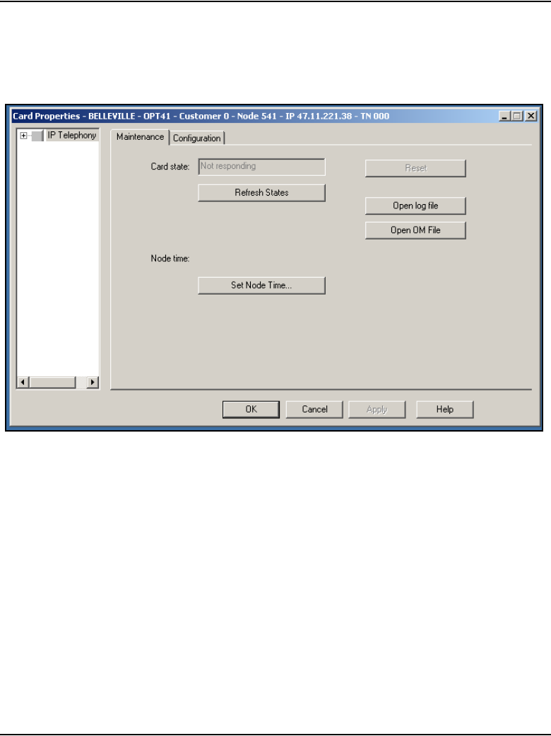
Page 508 of 910 Configuration of IP Telephony nodes using OTM 2.2
553-3001-365 Standard 4.00 August 2005
There are two tabs in the Card Properties window: Maintenance and
Configuration. See Figure 164 and see Figure 165 on page 509.
Figure 164
Card Properties – Maintenance tab
4Keep the default settings shown in the Maintenance tab. Click the
Configuration tab.
See Figure 165 on page 509.
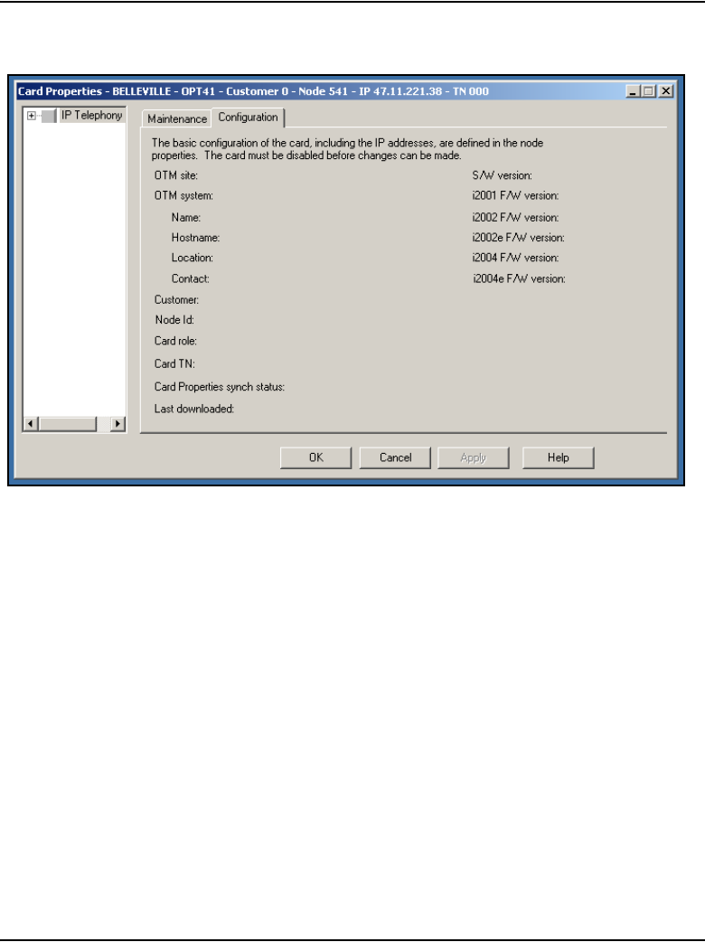
Configuration of IP Telephony nodes using OTM 2.2 Page 509 of 910
IP Line Description, Installation and Maintenance
Figure 165
Card Properties – Configuration tab
The current Voice Gateway Media Card software and IP Phone firmware
versions are displayed on the Configuration tab. The Voice Gateway
Media Card software is labelled S/W version and the IP Phone firmware
is labeled i2001, i2002, or i2004 F/W version.
5Write down the loadware and firmware version for each Voice Gateway
Media Card. Compare the loadware and firmware version with the latest
recommended software release on the Nortel web site.

Page 510 of 910 Configuration of IP Telephony nodes using OTM 2.2
553-3001-365 Standard 4.00 August 2005
6Check the Nortel web site for the latest IP Line 4.5 software and IP Phone
firmware releases. Download the files. See Appendix F on page 903.
Note: The IP Line 4.5 software files and IP Phone firmware files are
contained in the IP Line 4.50xx. SA file in the Internet Telephony
Gateway product list on the Nortel web site. The zipped file contains the
following:
•The IPL450xx.p2 and IPL450xx.sa loadware files. The IPL450xx.p2
file is the IP Line 4.5 application for the ITG-P 24-port line card. The
IPL450xx.sa is the IP Line 4.5 application for the Media Card.
•The 0602Bxx.BIN (Phase I IP Phone 2004), 0603Bxx.BIN (Phase I
IP Phone 2002), and 0604Dnn.BIN (Phase II IP Phone 2001,
IP Phone 2002, and IP Phone 2004) firmware files.
For example, a firmware version can be labelled 0602B38. This
means IP Phone firmware version 1.38.
— The 02 represents the IP Phone 2004.
— The letter B represents the version number.
— 38 represents the release number .38.
•A readme.txt file.
The readme.txt file explains important considerations when installing
the new software and firmware versions. The readme file also
includes identifying information for the software and firmware files
such as the date and time, size and checksum.
7Locate the saved file and double-click the *.zip file.
The zipped file opens in a compression utility program and the
uncompressed files are listed.
8If the card’s software and firmware are not up-to-date, transfer the
downloaded files (*.p2, *.sa, and firmware file(s)) from an
Internet-enabled PC to the OTM PC.
9If the card’s software and firmware are not up-to-date, upgrade the Voice
Gateway Media Card with the software and firmware files.

Configuration of IP Telephony nodes using OTM 2.2 Page 511 of 910
IP Line Description, Installation and Maintenance
Refer to Procedure 65, “Upgrading Voice Gateway Media Card software
from the OTM 2.2 PC” on page 512, and Procedure 67, “Upgrading the IP
Phone firmware” on page 517 for detailed instructions on how to perform
the upgrades.
Note: All cards must be running the same version of the software.
End of Procedure
Upgrade options
Once the Voice Gateway Media Card software and IP Phone firmware has
been verified, there are three upgrade options:
1Upgrade the Voice Gateway Media Card software.
– In this case, perform Procedure 65 on page 512 only.
This is the most frequently-used option is used; however, verify if an IP
Phone firmware upgrade is also required.
2Upgrade both the Voice Gateway Media Card software and IP Phone
firmware.
– In this case, perform a combination of Procedure 65 on page 512 and
Procedure 67 on page 517.
Note: Do not restart the Voice Gateway Media Cards until the end of
Procedure 67, as restarting the cards restarts all the IP Phones.
3Upgrade the IP Phone firmware.
– In this case, perform Procedure 67 on page 517 only.
Note: In this case, restart all IP Phones instead of all Voice Gateway
Media Cards. To do this, select a single test IP Phone and reset the
firmware only on that test telephone before completing the procedure on
all IP Phones. If the upgrade works properly, use the umsUpgradeAll
command to complete the upgrade on all the IP Phones.

Page 512 of 910 Configuration of IP Telephony nodes using OTM 2.2
553-3001-365 Standard 4.00 August 2005
Upgrade Voice Gateway Media Card software
To upgrade the software on the Voice Gateway Media Card, follow the steps
in Procedure 65.
If Procedure 64 has just been completed, the correct software should have
been verified and obtained for the Voice Gateway Media Card, and the files
transferred to the OTM PC.
Note: A node can contain a mix of Media Cards 32-port and 8-port line
cards and ITG-P 24-port line cards. Each card type has a different
software version. If a node contains a mix of cards, the software upgrade
must be performed separately for each card type. That is, upgrade the
ITG-P 24-port line card’ software and then the Media Card line card’s
software. Downloading ITG-P software to a Media Card takes that
Media Card out of service. If this happens, it is not possible to restore the
Media Card to service by downloading the correct software after the
incorrect software has been used.
Procedure 65
Upgrading Voice Gateway Media Card software from the OTM 2.2 PC
1Open the OTM Navigator, and click on the Services folder. Double-click
the IP Telephony icon.
The IP Telephony window opens.
2Select the Voice Gateway Media Cards that are to be upgraded from the
main card list view. Upgrade all the cards in the node together, unless a
spare card that has older software is being installed.
3Disable all Voice Gateway Media Cards to be upgraded. Use the LD 32
DISI command from OTM Maintenance Windows, the OTM System
Passthru terminal, or a system management terminal directly connected
to a TTY port on the system.
Note: Nortel recommends that a Voice Gateway Media Card be disabled
before upgrading the software. However, it is possible to perform the
transfer of the software to the card while the card is enabled. A Voice
Gateway Media Card does not have to be disabled to transfer the
software; however, the card must be disabled before it is rebooted.
4In the IP Telephony Gateway - IP Line 4.5 main window, select
View > Refresh and verify that the card status is showing “Disabled.”
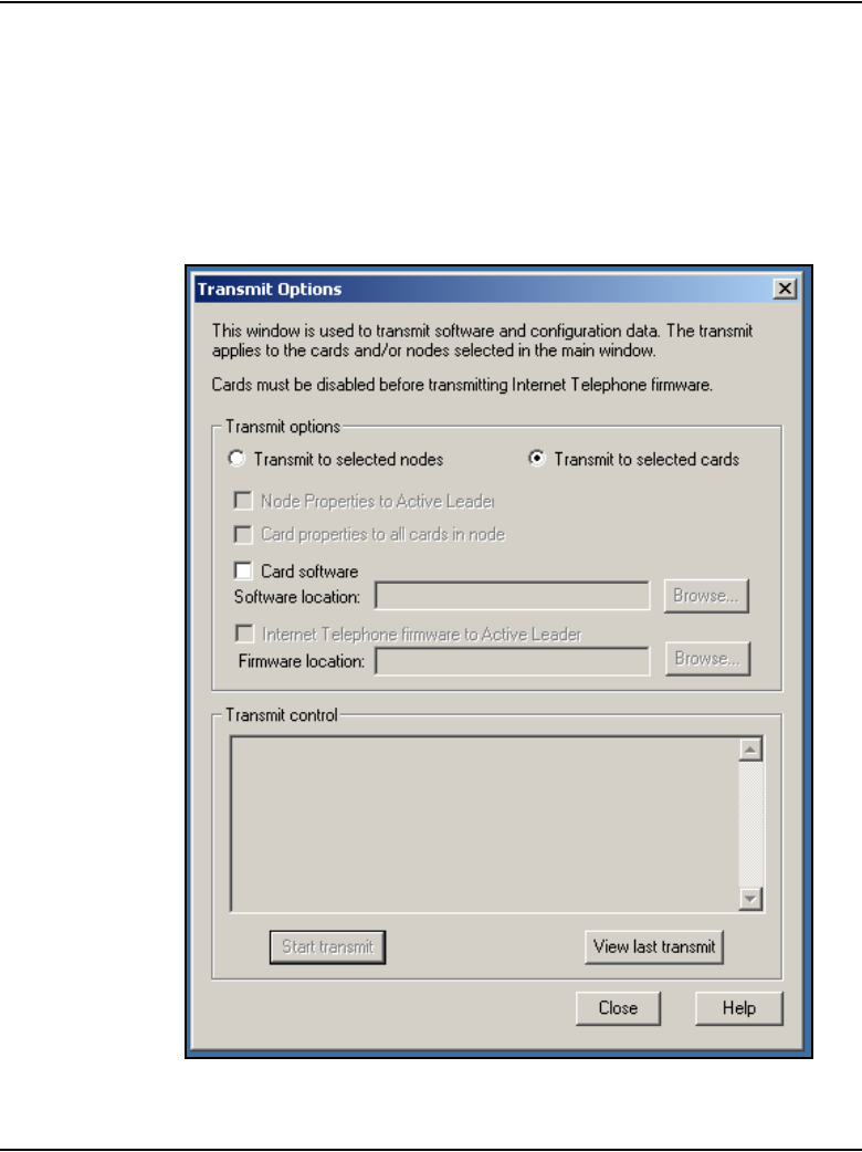
Configuration of IP Telephony nodes using OTM 2.2 Page 513 of 910
IP Line Description, Installation and Maintenance
5Select Configuration > Synchronize > Transmit.
The Transmit Options dialog box is displayed. See Figure 166 on
page 513.
6Under Transmit options, select the Transmit to selected cards radio
button.
Figure 166
Transmit Options window

Page 514 of 910 Configuration of IP Telephony nodes using OTM 2.2
553-3001-365 Standard 4.00 August 2005
7Select the Card software check box.
8Click on the Browse button to the right of the Software location text box.
9Select the appropriate file filter (that is, *.sa, *.p2, *.mms, *.*) from the
Files of type: drop-down list.
10 Locate the Voice Gateway Media Card software that was verified to be the
correct version in Procedure 64 on page 507. Select the file and click
Open to save the selection.
The path and file name of the Voice Gateway Media Card loadware
appears in the Software location text box.
11 Click Start transmit to begin the Voice Gateway Media Card software
upgrade process.
The software is transmitted to each card in turn, and burned into the flash
ROM on the Voice Gateway Media Card.
12 Monitor progress in the Transmit control window. Confirm that the card
software is transmitted successfully to all cards. Note any error
messages, investigate and correct any problems, and repeat card
software transmission until it is completed successfully for each Voice
Gateway Media Card.
The cards continue to run the old software until they are rebooted.
13 Reboot each Voice Gateway Media Card that received the transmitted
software.
This enables the new loadware to take effect. Reboot Leader 0 first,
followed by the other cards.
These cards must remain in the “Disabled” state after the upgrade, so that
a “Reset” command can be issued from the Maintenance menu.
Alternatively, click the Reset button on the Maintenance tab in the Card
Properties window of each card to reboot the cards. Also, the cards can
be reset by using a pointed object to press the “Reset” button on the card
faceplate.
WARNING
Do not use a pencil to reset the Voice Gateway Media
Card. The graphite carbon can create an electrical short
circuit on the board.

Configuration of IP Telephony nodes using OTM 2.2 Page 515 of 910
IP Line Description, Installation and Maintenance
14 After all the Voice Gateway Media Cards have been reset, have
successfully rebooted, and are responding again to the OTM 2.2 IP Line
4.5 application, do a Status refresh (disabled: active; disabled: backup;
disabled).
15 Double-click each upgraded card and verify the card software version in
the S/W version field of the Configuration tab in the Card Properties
window.
16 Use the LD 32 ENLC command to re-enable the Voice Gateway Media
Cards.
Use LD 32 in the TTY or OTM Overlay passthru to re-enable the Voice
Gateway Media Card with one of the following commands:
• ENLC l s c (for Meridian 1 Large Systems)
• ENLC c (for Meridian 1 Small Systems)
17 Repeat the previous two steps for each Voice Gateway Media Card.
End of Procedure
Upgrade the Voice Gateway Media Card software
The minimum versions of IP Line 4.5 software for the Voice Gateway Media
Card vintages earlier than NTVQ01BB and NTVQ01AB are:
• Version 6.8 for the Media Card
• Version 5.7 for the ITG-P 24-port card
The minimum versions of IP Line 4.5 software for the Voice Gateway Media
Cards NTVQ01BB and NTVQ01AB is Version 8.2. There is no need to
download the Version 8.2 software for the Voice Gateway Media Cards
NTVQ01BB and NTVQ01AB as the software is pre-loaded at the factory.
Note: Refer to the ReadMe First document or the General Release
Bulletin to ensure that the latest firmware is identified.
To upgrade the IP Line software for the Voice Gateway Media Card, follow
the steps in Procedure 66 on page 516.

Page 516 of 910 Configuration of IP Telephony nodes using OTM 2.2
553-3001-365 Standard 4.00 August 2005
Procedure 66
Upgrading the Voice Gateway Media Card software
1Check the Nortel web site for the most current versions of the IP Line
software for the ITG-P 24-port line card and Media Card line cards.
2Once the most current version of the software has been downloaded,
follow the steps in:
• Procedure 105 on page 763 to upgrade the software on the ITG-P
24-port line card
• Procedure 106 on page 766 to upgrade the software on the Media
Card line cards
End of Procedure
Upgrade the IP Phone firmware
When the IP Line 4.5 software has been upgraded on the Voice Gateway
Media Card, verify if an IP Phone firmware upgrade is also required. Check
the Readme First document for the OTM IP Line 4.5 application to determine
which IP Phone firmware version is required to be compatible.
Note: The firmware upgrade procedure does not apply to the IP
Softphone 2050 and the MVC 2050.
• In Procedure 64 on page 507, the correct software for the Voice Gateway
Media Card should have been obtained and verified. The files should
have been transferred to the OTM PC.
• If using Procedure 65 on page 512 and Procedure 67 on page 517
together, do not restart the Voice Gateway Media Card until
Procedure 67 is completed. All the cards must be restarted because the
software has not been upgraded. The new software will not run until the
cards are rebooted, because the new firmware is incompatible with the
old software.
• If using Procedure 67 on page 517 alone (a firmware upgrade only), it is
only necessary to reboot the node.

Configuration of IP Telephony nodes using OTM 2.2 Page 517 of 910
IP Line Description, Installation and Maintenance
To upgrade the firmware on the IP Phone, follow the steps in Procedure 67.
This procedure has two major components:
• placing the IP Phone firmware onto each card in the node
• propagating the firmware from the card to each IP Phone registered on
that card
Procedure 67
Upgrading the IP Phone firmware
1Open OTM Navigator, and click the Services folder. Double-click the
IP Telephony icon.
The IP Telephony window opens.
2In the main card list view, disable all Voice Gateway Media Cards that are
to be upgraded with the new firmware.
All cards must have the same IP Phone firmware version.
3Verify that all Voice Gateway Media Cards that require a firmware
upgrade have established a signaling link with the Call Server.
Note: The Voice Gateway Media Cards must first be disabled in order to
update the firmware. Use the LD 32 DISI command from OTM
Maintenance Windows, the OTM system Passthru terminal, or a system
management terminal directly connected to a TTY port.
To verify that the link is available between the Call Server and Voice
Gateway Media Card, Telnet to each card and log in. From the command
line, type pbxLinkShow. The status of the Call Server link appears. If the
link is active, the screen displays the following:
RUDPLinkState = Up
4Select Configuration > Synchronize > Transmit.
The Transmit Options dialog box is displayed. See Figure 167 on
page 518.
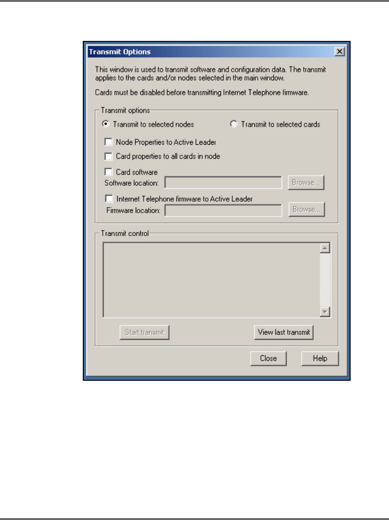
Page 518 of 910 Configuration of IP Telephony nodes using OTM 2.2
553-3001-365 Standard 4.00 August 2005
Figure 167
Transmit Options window
5Under Transmit options, click the Transmit to selected nodes radio
button.
6Select the IP Phone firmware to Active Leader check box.
7Click on the Browse button to the right of the Firmware location text box
to locate the IP Phone firmware that was previously verified as required
for the Voice Gateway Media Card software version. Select the firmware
file, and click Open.
Configuration of IP Telephony nodes using OTM 2.2 Page 519 of 910
IP Line Description, Installation and Maintenance
The path and file name of the IP Phone firmware appears in the Firmware
location text box.
The IP Line 4.5 software determines the target IP Phone type (2001,
2002, or 2004) based on the firmware filename. A filename of the format
xx02xxx.BIN (where “x” can be any alpha-numeric character) represents
a firmware file for the Phase I IP Phone 2004. Similarly a filename of the
format xx03xxx.BIN represents a firmware file for the Phase I IP Phone
2002. A filename of the format xx04xxx.BIN represents a firmware file for
the Phase II IP Phone 2001, IP Phone 2002, IP Phone 2004, IP Phone
2007, and IP Phone Audio Conference Phone 2033.
8Click the Start transmit button to begin upgrading the IP Phone firmware
on the Voice Gateway Media Cards.
9Monitor progress in the Transmit control window. Confirm the card
firmware is transmitted successfully to all cards. Note any error
messages, investigate, correct any problems, and repeat card firmware
transmission until it is completed successfully on each Voice Gateway
Media Card.
The IP Phones continue to run the old firmware until each telephone
reregisters with a Voice Gateway Media Card that contains the new IP
Phone firmware.
Note: Commands are available from the IPL> command line to upgrade
a single IP Phone immediately, all IP Phones immediately, or schedule all
IP Phones to be upgraded at a later time. Before doing this, verify that
each card has the correct firmware version and check the date and time
on the node.
10 Select an IP Phone for test purposes. Telnet to the Voice Gateway Media
Card. Log into the IPL> command line, and enter the following:
iSetReset “xxx.xxx.xxx.xxx”
where xxx.xxx.xxx.xxx is the IP Address of the selected IP Phone.
CAUTION
Downloading an incorrect version of the IP Phone
firmware can result in extended service interruptions and
require special recovery procedures.

Page 520 of 910 Configuration of IP Telephony nodes using OTM 2.2
553-3001-365 Standard 4.00 August 2005
11 Monitor the display on the test telephone. As it upgrades the firmware,
note the IP Address of the Voice Gateway Media Card from where the test
telephone is receiving its upgrade.
12 Press the Services key (key with globe with arrow pointing East and
West) on the IP Phone. The Services key provides access to the
Telephone Options list.
a. Press Select to select Telephone Options.
b. Use the Navigation keys to scroll to Set Info.
c. Press the Select softkey, then press the Navigation keys until it
displays FW Version:. For the Voice Gateway Media Card, select the
appropriate firmware.
Note: For example, a firmware version can be labeled 0602B38, which
means IP Phone firmware version 1.38.
• 02 represents the IP Phone 2004.
• B represents the Version number 1.
• 38 represents the Release number .38
13 Lift the handset and make a call to verify the IP Phone works.
14 When the IP Phone is working, verify the date and time on the node.
Ensure each Voice Gateway Media Card has the correct loadware and
firmware before using the umsUpgradeAll command to upgrade all the
IP Phones.
To verify the date and time on the node from OTM 2.2, select the node in
the top of the IP Telephony Gateway - IP Line 4.5 window.
15 Double-click on Leader 0 in the bottom of the window.
The Card Properties window opens.
Note: Cards receive their time from the Leader 0 card. If the time for
Leader 0 is correct, all cards on the node should be the same. If Leader 0
displays the incorrect time, reset the time. The time propagates to the
other cards.
16 Click the Maintenance tab. This displays the Node time. If the time is
incorrect, click on the Set Node Time button.
The Set Node Time window opens. Under Time and date, set the Time,
where the time is displayed in the HH:MM:SS AM/PM format. Click OK to
close the window.

Configuration of IP Telephony nodes using OTM 2.2 Page 521 of 910
IP Line Description, Installation and Maintenance
17 Click the Configuration tab. Note the card’s software version and the
IP Phone firmware version.
Double-click on each card to verify the software and firmware version. Do
this for every card.
18 Before proceeding, ensure the time on the card is set correctly. Telnet to
each Voice Gateway Media Card and log in. At the IPL> command line,
enter the following:
umsUpgradeAll “hh:mma/p”
hh:mma/p specifies the time when the upgrade will occur, a represents
A.M., and p represents P.M. The time is in Standard format.
Example:
umsUpgradeAll “11:30a” or umsUpgradeAll “2:45p”.
At the time specified, all the IP Phones on the Voice Gateway Media Card
go out of service. This can take several minutes.
Upon completion of the firmware upgrade, the IP Phones are brought
back online in groups of ten.
After the test telephone is working, umsUpgradeAll does not need the
time parameter. However, without the time parameter, the command
immediately resets all the IP Phones currently registered on that line card.
If the technician does not want to immediately reset all the phones, and
wants to schedule the reset time of the IP Phones, check the time on all
the cards. If necessary, reset the time to ensure all cards have the same
time. Then issue the umsUpgradeAll “hh:mma/p” command, where
“hh:mma/p” represents the time when the upgrade will occur.
19 At the IPL> prompt, verify that the IP Phones are upgraded for each Voice
Gateway Media Card by entering the following command:
isetShow
Inspect the list to ensure all IP Phones have the correct firmware version.
WARNING
The umsUpgradeAll command (without the time
parameter) causes the IP Phones registered on all cards
that are logged into to be immediately taken out of
service, unless the time parameter is specified.

Page 522 of 910 Configuration of IP Telephony nodes using OTM 2.2
553-3001-365 Standard 4.00 August 2005
20 For any IP Phones that did not upgrade successfully, try one of the
following (in order):
• use the isetReset ''IP Address'' command
• enter the following combination of keystrokes on the IP Phone:
release, mute, up, down, up, down, up, mute, 9, release
• power the IP Phone off and then on again
If the upgrade was unsuccessful on any of the IP Phones, this is probably
due to one of the following reasons:
• one of the Voice Gateway Media Cards did not upgrade the software
successfully
• an IP Phone is loaded with a firmware version that was unable to be
upgraded by the Voice Gateway Media Card in the normal manner
•the umsUpgradeAll command was not issued
• one of the cards has not been reset
If the upgrade was unsuccessful, re-do the appropriate procedure. If
the upgrade is still unsuccessful, contact the technical support
representative for further assistance.
End of Procedure
For additional information on configuring the IP Phones, the IP Softphone
2050, and the MVC 2050, refer to IP Phones: Description, Installation, and
Operation (553-3001-368).
Upgrading the MVC 2050
For information on upgrading the MVC 2050 software, refer to the
Nortel Mobile Voice Client 2050 User Guide.

Configuration of IP Telephony nodes using OTM 2.2 Page 523 of 910
IP Line Description, Installation and Maintenance
Configure OTM Alarm Management to receive IP Line
SNMP traps
To configure the alarm notification feature in OTM 2.2 to receive SNMP
traps, follow the steps in Procedure 68.
For more information about OTM Alarm Management, refer to Optivity
Telephony Manager: System Administration (553-3001-330).
Procedure 68
Configuring SNMP Traps
1In the OTM Navigator window, select the Utilities menu option and click
on Alarm Notification.
See Figure 168 on page 524.
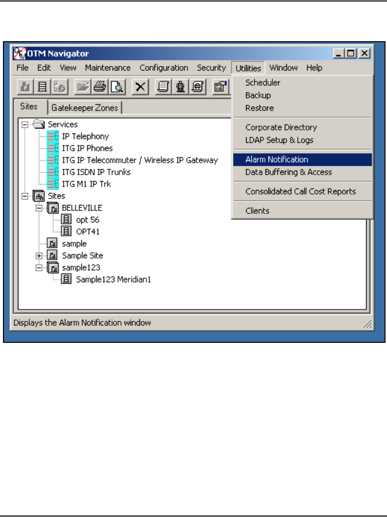
Page 524 of 910 Configuration of IP Telephony nodes using OTM 2.2
553-3001-365 Standard 4.00 August 2005
Figure 168
OTM Navigator – Utilities > Alarm Notification
The OTM Alarm Notification window opens.
2Select Configuration > Run Options.
The Alarm Notification Run Options dialog box opens.
3Click the Control Files tab.
See Figure 169 on page 525.
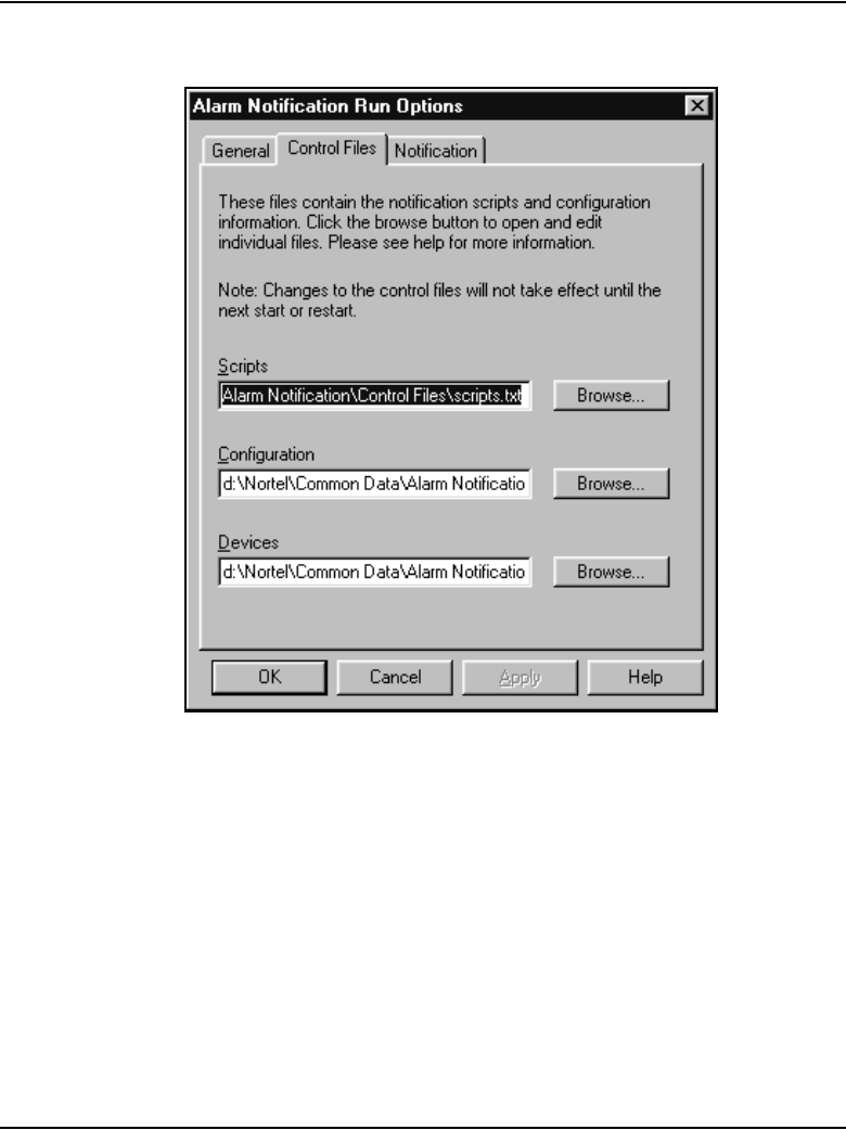
Configuration of IP Telephony nodes using OTM 2.2 Page 525 of 910
IP Line Description, Installation and Maintenance
Figure 169
Alarm Notification Run Options – Control Files tab
4Click the Browse button located to the right of the Devices text box.
The Open dialog box opens.
5Select the Devices file from the Control Files folder and click Open.
See Figure 170 on page 526.
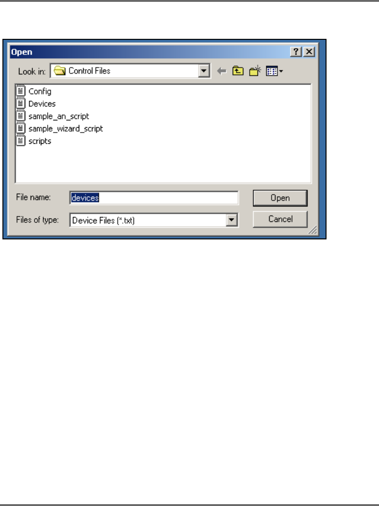
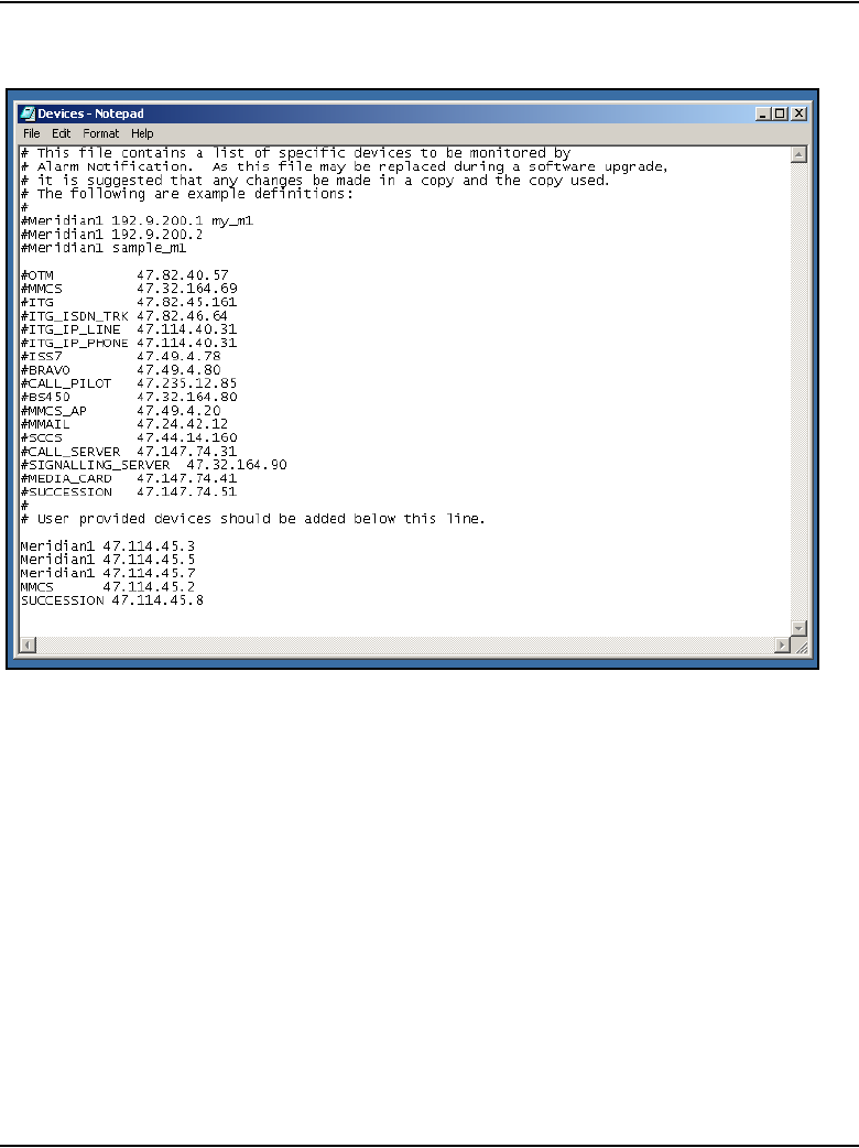
Configuration of IP Telephony nodes using OTM 2.2 Page 527 of 910
IP Line Description, Installation and Maintenance
Figure 171
Devices.txt file
6For each Voice Gateway Media Card in each monitored IP Telephony
node, add a line consisting of three fields separated by spaces, as shown
in Table 72 on page 528. Enter the first line under the last line that begins
with a “#”.
7Click File > Save As.
Save the template as a new file, for example, ITGDevices1.txt, to avoid
overwriting the template file.
8In the Alarm Notification Run Options window, verify that the devices
field name is correct (ITGDevices1.txt). Click Apply, and then OK.
Note: OTM Alarm Notification must be restarted whenever Control Files
are changed.

Page 528 of 910 Configuration of IP Telephony nodes using OTM 2.2
553-3001-365 Standard 4.00 August 2005
9If OTM Alarm Notification is running (the red traffic light is showing on the
toolbar), click on the red traffic light to stop alarm notification. The traffic
light changes to green. Click the green traffic light to restart alarm
notification. The traffic light should turn to red to indicate it is running.
If OTM Alarm Notification is not running, as indicated by the green traffic
light, click on the green traffic light to change it to red. This starts Alarm
Notification.
10 Telnet to each Line card and log in. At the IPL> command line, enter
itgAlarmTest.
A series of SNMP traps is emitted by the Voice Gateway Media Card and
appears in the OTM Alarm Notification browser window. Verify that the
device name identifies the correct Voice Gateway Media Card.
For every Voice Gateway Media Card in every node, there is a line in the
table. For example, a line in the table can look like this:
ITG_IP_PHONE 192.9.200.1 MySite_MySystem_Leader_1
The following is a description of each field in the table:
Device Type – a dedicated receive string or name used as an index for
the IP Line application. The Device Type must be ITG_IP_PHONE.
IP Address – the source IP address on the Voice Gateway Media Card
from which the traps are coming (either the card Voice (TLAN) network
interface IP address or card Management (ELAN) network interface IP
address). By default, the SMNP traps are issued from the card Voice
(TLAN) network interface IP address. If a card routing table entry on the
IP Telephony node was previously configured pointing to the IP address
of the OTM, then the SMNP trap issues from the Management (ELAN)
network interface of the card.
Table 72
Format of Devices.txt file
Device Type IP Address Device Name
ITG_IP_PHONE xxx.xxx.xxx.xxx Site_Leader_0
ITG_IP_PHONE xxx.xxx.xxx.xxx Site_Leader_1
ITG_IP_PHONE xxx.xxx.xxx.xxx Site_Follower_2

Configuration of IP Telephony nodes using OTM 2.2 Page 529 of 910
IP Line Description, Installation and Maintenance
Device Name – the device name can be any string. Nortel recommends
that abbreviations for the site and system, the card functions, and the
Terminal Numbers (TNs) are used, such as
Site_System_Leader/Follower_TN. Note: Spaces should not be used in
the Device Name. Use an underscore (_) as a separator.
The Leader card has two IP addresses: the card voice IP address (TLAN)
and the node IP address. The Follower cards have only a single IP
address, the TLAN IP address.
End of Procedure
Assemble and install an IP Phone
To assemble and install an IP Phone, refer to IP Phones: Description,
Installation, and Operation (553-3001-368).
Change the default IPL> CLI Shell password
The IPL> CLI is password-protected for Telnet access and access to the local
maintenance port. The same user name and password also protects FTP
access to the Voice Gateway Media Card. The IPL> CLI has a default user
name of itgadmin and a default password of itgadmin.
Refer to “IPL> CLI Shell user name and password” on page 539 and “Node
password synchronization” on page 541 for more detailed information on the
passwords.
Configure the IP Phone Installer Passwords
The IP Phone Installer Password protection, required for changing the TN on
the IP Phone, controls registration with a virtual line TN on the Call Server.
See page 543 for more information about the IP Phone Install Passwords.
To enable and set the administrative IP Phone Installer Password, see
Procedure 69 on page 553. If needed, enable and configure a temporary
IP Phone Installer Password. See Procedure 70 on page 556.

Page 530 of 910 Configuration of IP Telephony nodes using OTM 2.2
553-3001-365 Standard 4.00 August 2005

Page 531 of 910
IP Line Description, Installation and Maintenance
570
IP Line 4.5 administration
Contents
This section contains information on the following topics:
Introduction . . . . . . . . . . . . . . . . . . . . . . . . . . . . . . . . . . . . . . . . . . . . . . 532
IP Line feature administration. . . . . . . . . . . . . . . . . . . . . . . . . . . . . . . . 533
Corporate Directory . . . . . . . . . . . . . . . . . . . . . . . . . . . . . . . . . . . . . 533
Private Zone configuration . . . . . . . . . . . . . . . . . . . . . . . . . . . . . . . . 534
Virtual Office . . . . . . . . . . . . . . . . . . . . . . . . . . . . . . . . . . . . . . . . . . 534
e911 . . . . . . . . . . . . . . . . . . . . . . . . . . . . . . . . . . . . . . . . . . . . . . . . . 536
802.1Q . . . . . . . . . . . . . . . . . . . . . . . . . . . . . . . . . . . . . . . . . . . . . . . 537
Password security . . . . . . . . . . . . . . . . . . . . . . . . . . . . . . . . . . . . . . . . . 538
SNMP community name strings. . . . . . . . . . . . . . . . . . . . . . . . . . . . 538
IPL> CLI Shell user name and password. . . . . . . . . . . . . . . . . . . . . 539
Node password synchronization. . . . . . . . . . . . . . . . . . . . . . . . . . . . 541
IP Phone Installer Password . . . . . . . . . . . . . . . . . . . . . . . . . . . . . . . 543
Default user name and password . . . . . . . . . . . . . . . . . . . . . . . . . . . 557
IP configuration commands . . . . . . . . . . . . . . . . . . . . . . . . . . . . . . . . . 559
TLAN network interface configuration commands . . . . . . . . . . . . . . . 559
Display the number of DSPs . . . . . . . . . . . . . . . . . . . . . . . . . . . . . . . . . 561
Display IP Telephony node properties . . . . . . . . . . . . . . . . . . . . . . . . . 561
Display Voice Gateway Media Card parameters . . . . . . . . . . . . . . . . . 563
Packet loss monitor . . . . . . . . . . . . . . . . . . . . . . . . . . . . . . . . . . . . . . . . 566
Transfer files using the CLI . . . . . . . . . . . . . . . . . . . . . . . . . . . . . . . . . 567
Download the IP Line 4.5 error log. . . . . . . . . . . . . . . . . . . . . . . . . . . . 569

Page 532 of 910 IP Line 4.5 administration
553-3001-365 Standard 4.00 August 2005
Reset the Operational Measurements file . . . . . . . . . . . . . . . . . . . . . . . 569
Introduction
This chapter explains how to administer IP Line 4.5 and the Voice Gateway
Media Cards on the Meridian 1 and CS 1000 systems.
Administration procedures include activities such as monitoring the system
status, operational reports, performing upgrades, changing configuration, and
adding, changing, and removing cards. Administration does not include
engineering, provisioning, initial installation and configuration, maintenance,
or troubleshooting.
The Voice Gateway Media Card provides four administration interfaces:
• Optivity Telephony Manager (OTM) 2.2
OTM’s IP Line 4.5 application provides a GUI to the Voice Gateway
Media Card. OTM 2.2 is used to Telnet to the card, install and upgrade
software and firmware, configure alarm event reporting, view and update
a card’s property and configuration data, add new cards to a node,
schedule reports and other related tasks.
• Element Manager
Element Manager is a web server that provides a GUI using the Internet
Explorer 6.0.2600 (or later) web browser. Element Manager is used to
Telnet to the card, install and upgrade software and firmware, configure
alarm event reporting, view and update card property and configuration
data, add new cards to a node, schedule reports, and other related tasks.
• IPL> Command Line Interface (CLI)
Use the CLI to display card and node status, change passwords, check
software versions, view channel states, and other card information. The
CLI is also used for expert level support and debug. The prompt for the
CLI on the Voice Gateway Media Card is IPL>. Access the CLI through
a direct serial connection to the I/O panel serial port, the Maint Port on

IP Line 4.5 administration Page 533 of 910
IP Line Description, Installation and Maintenance
the faceplate, or through a Telnet session. Use a VT-100 terminal
emulation program set to 9600 baud, 8 bits, no parity, one stop bit.
• Overlays
IP Line feature administration
Corporate Directory
LD 11 accepts Class of Service (CLS) CRPA/CRPD for IP Phones.
The Call Server service change does not affect Corporate Directory
immediately. If an IP Phone is in Corporate Directory mode, and there is a
service change to configure CLS as CPRD, then the current display and key
handling should not be affected. The changed CLS occurs only when the user
quits the Corporate Directory application and enters again.
For more information about the operation of the Corporate Directory feature,
refer to Optivity Telephony Manager: Installation and Configuration
(553-3001-230).
Note: Corporate Directory is not supported on the IP Phone 2001 and
IP Audio Conference Phone 2033.
Table 73
Corporate Directory: LD 11 configuration
Prompt Response Description
REQ: NEW CHG Add new data or change existing data.
TYPE: i2002
i2004
i2050
Enter terminal type.
TN l s Enter IP Phone TN.
...
CLS CRPA CRPD Enable/Disable the Corporate Directory feature for this TN.

Page 534 of 910 IP Line 4.5 administration
553-3001-365 Standard 4.00 August 2005
Private Zone configuration
DSP channels and IP Phones are set as Shared or Private based on zone
configuration. This is accomplished through the parameter
zoneResourceType in the zone configuration commands in LD 117.
The <zoneResourceType> parameter specifies the zone to be either shared or
private.
A zone is configured in LD 117 as follows:
NEW ZONE <zoneNumber> [<intraZoneBandwidth>
<intraZoneStrategy> <interZoneBandwidth> <interZoneStrategy>
<zoneResourceType>]
CHG ZONE <zoneNumber> [<intraZoneBandwidth>
<intraZoneStrategy> <interZoneBandwidth> <interZoneStrategy>
<zoneResourceType>]
By default, a zone is configured as Shared (zoneResourceType=shared).
Virtual Office
The IP Phone Virtual Office feature uses the Station Control Password
(SCPW) feature. The SCPW password can be maintained either through LD
11 administration or by the user if Flexible Feature Code (FFC) code access
is configured. If the SCPW is not configured for a TN registering by means
of the Virtual Office feature, the login is rejected. An appropriate error
message is displayed to alert the user that a password must be configured.
Enable the SCPW in the Customer Data Block (CDB) by configuring the
length of the SCPW (scpl). The SCPW must be at least four digits.
To login using Virtual Office, the TN associated with the current IP Phone
registration must be configured with the CLS VOLA (Virtual Office Login
Allowed). The TN associated with the User ID for the login must be
configured with the CLS VOUA (Virtual Office User Allowed).

IP Line 4.5 administration Page 535 of 910
IP Line Description, Installation and Maintenance
Two CLSs restrict Virtual Office usage. The two classes of services are:
• VOLA/VOLD – defines whether this TN (physical IP Phone)
allows/disallows a Virtual Office login option.
• VOUA/VOUD – defines if a specific remote user can log onto this TN
(allows/disallows a particular user to login using Virtual Office).
Table 74 shows the CLS for LD 11.
Table 74
LD 11 – Virtual Office Login for IP Phones (Part 1 of 2)
Prompt Responses Description
REQ: NEW
CHG
TYPE: i2001
i2002
i2004
i2050
For IP Phone 2001, IP Phone 2002, and IP Phone
2004, IP Softphone 2050, or MVC 2050. The system
accepts this response if it is equipped with packages
88 and 170. The IP Phone 2001 and IP Phone 2002,
IP Softphone 2050, and MVC 2050 are also
restricted by the IP Phone License setting.
Note: The IP Phone 2007 uses set type i2004. The
IP Audio Conference Phone uses set type i2001.
CUST xx Customer number as defined in LD 15
BUID <user id> Dialable DN, main office user ID
Enter X to delete.
MOTN l s c u Main Office Terminal Number
Format for Large System and CS 1000E system,
where l = loop, s = shelf, c = card, u = unit.
Accept default for CS 1000S, Media Gateway
1000B, Media Gateway 1000T, or Small System
Main Office
...

Page 536 of 910 IP Line 4.5 administration
553-3001-365 Standard 4.00 August 2005
e911
If 911 is dialed while logged into Virtual Office, the LTPS re-directs the 911
call to the local area 911 service (PSAP), not the remote Call Server 911
service. Table 75 describes the process.
CLS (VOLA VOLD Virtual Office login operation is allowed/denied on
this TN
CLS (VOLA) VOUD Allow/Disallow Virtual Office user on this TN using
other IP Phone
Table 75
e911 process
Step Description
1The LTPS aborts the call on the remote Call Server.
2The LTPS displays Emergency Call on the IP Phone.
3The LTPS logs the IP Phone out of Virtual Office.
4The LTPS reconnects to the local Call Server.
Table 74
LD 11 – Virtual Office Login for IP Phones (Part 2 of 2)
Prompt Responses Description

IP Line 4.5 administration Page 537 of 910
IP Line Description, Installation and Maintenance
Configuration
The Emergency Services Access (ESA) feature must be configured on all
nodes participating in Virtual Office logins. No other special configuration is
required.
For more information, refer to Emergency Services Access: Description and
Administration (553-3001-313).
802.1Q
The 802.1Q support for IP Phones is configured and controlled using the
telephone’s user interface or DHCP. The DHCP approach eliminates the
requirement to manually set the VLAN ID as part of the installation. The
configuration is composed of two items: setting the “p” bits and setting the
VLAN ID.
5The LTPS restarts the 911 call, thus reaching the correct PSAP.
Note: The extra processing adds 5 seconds to the call setup time.
6After the emergency call ends, the IP Phone remains registered to the Home
LTPS as a normal telephone, in case the PSAP makes a call back to the
originator of the emergency call.
After the IP Phone is redirected to its Home Site, it is not allowed to initiate a new
operation for five minutes. This prevents the user from accidentally dialing the
emergency DN and hanging up. In this case, the emergency response personnel
might call back to confirm the accidental call (and thus confirm that there is no
emergency). If the IP Phone were allowed to immediately resume a Virtual Office
login to another site, it could not receive the call back.
If the local TN has another IP Phone Virtual Office logged into it when it comes
back, the non-emergency IP Phone is pre-empted.
Note: If this occurs, ESAxxx messages are generated on the system TTY.
Table 75
e911 process
Step Description

Page 538 of 910 IP Line 4.5 administration
553-3001-365 Standard 4.00 August 2005
OTM 2.2 and Element Manager have two fields for setting 802.1Q support:
• Enable 802.1Q support: A check box that, when checked, sets the priority
bits to the value specified by the next item. If the check box is unchecked,
the IP Phone sends out the default priority of 6.
• 802.1Q Bits value (802.1p): A 802.1Q priority bit value field that sets the
value the IP Phone sent out in the priority field. The range is 0 – 7.
Password security
The following password security features must be configured and
administered in IP Line 4.5:
1SNMP community name strings
2IPL> CLI Shell password
3Call Server’s Level 1 Password (PWD1)
4IP Phone Installer Password
The SNMP community name strings, IPL> CLI Shell password, and Call
Server’s Level 1 Password (PWD1) operate at the card level. The IP Phone
Installer Password works at the node level.
• The SNMP community name strings are contained in the card properties
that were transmitted to each Voice Gateway Media Card.
• The IPL> CLI Shell password is configured on each individual Voice
Gateway Media Card.
• The Level 1 Password (PWD1) is set at the Call Server and is sent to all
Voice Gateway Media Cards in the node.
• The IP Phone Installer Password is first applied to one Voice Gateway
Media Card in the node, and then is applied to all the Voice Gateway
Media Cards in the node.
SNMP community name strings
SNMP community name strings are required to access the Voice Gateway
Media Card. There are three community names: public, admingroup2, and
admingroup3.

IP Line 4.5 administration Page 539 of 910
IP Line Description, Installation and Maintenance
OTM 2.2 stores the community names for Meridian 1 systems. See
Figure 155 on page 486. Procedure 57 on page 486 explains how to change
the SNMP community names to control access to the IP Telephony node.
Element Manager stores the community names for CS 1000 systems. See
Figure 87 on page 378. Procedure 28 on page 378 is used to change the
SNMP community name to control access to the IP Telephony node.
IPL> CLI Shell user name and password
The IPL> Command Line Interface (CLI) is password-protected to control
Telnet access and access to the local maintenance port. The same user name
and password also controls FTP access to the Voice Gateway Media Cards.
Login banner
The IP Line 4.5 login banner information includes the IP Line 4.5 Voice
Gateway Media Card loadware version, ELAN network interface IP address,
card type, firmware version, current time and date, system name, system
location, and system contact.
The following information is an example of the login banner displayed on the
Media Card:
Login:
Password
Welcome to the IP Line command line.
Software Version: IPL-4.50.01
Management IP: 47.11.216.216
Host Type: Media Card
Firmware Version: ITG Firmware Rls 5.7
SysName: ITG Line
SysLocation: TN 10 0
SysContact: designer
OS Time: Date (04/03/2005) Time (09:07:43)
Use “logout” to logout.
Idle session timeout = 20 minutes.
IPL>

Page 540 of 910 IP Line 4.5 administration
553-3001-365 Standard 4.00 August 2005
Password Guessing Protection
IP Line 4.5 provides protection against password guessing. This protection
helps to block a hacker from attempting to log into the Voice Gateway Media
Card’s shell by making repeated attempts to guess the shell user ID and
password.
The password guessing protection is applicable to either a tip session (direct
maintenance port-connected TTY session) or a Telnet session.
The password guessing protection feature is described as follows:
• There is a login failure threshold of 3 and a lockout period of 10 minutes.
This is not user-configurable.
• Password guessing protection is enabled by default when the card starts
the first time. The protection can be disabled and re-enabled at the
VxWorks shell. Entering the shellLoginProtectSet 0 command disables
the protection and shellLoginProtectSet 1 enables it.
• When the login failure threshold is exceeded (by 3 consecutive failed
login attempts), the system raises an “ITG1038” critical alarm. This
alarm is sent to indicate the card’s login has been locked due to too many
incorrect password entries.
Alarm value = ITG alarm 38
perceivedSeverity = Critical
probableCause = Unauthorized maximum access attempts
Alarm text = IPL login protection (login locked)
When the 10 minute timer expires for the lockout period, the system
raises an “ITG5038” cleared alarm. The clear message is sent after the
lockout period expires.
perceivedSeverity = Cleared
probableCause = Unauthorized maximum access attempts
Alarm text = IPL login protection (login available)
• There is no online indication or warning during the failed login attempt
lockout state. Everything appears the same to the user trying to login. The
user is not informed that login blocking has been activated. The login is
ignored for 10 minutes.

IP Line 4.5 administration Page 541 of 910
IP Line Description, Installation and Maintenance
Note: Both the “critical” and “cleared” alarms send an SNMP trap to the
system administrator. For security reasons, these two alarms do not call
the syslog function as the other itgAlarms do, so no syslog message is
displayed on the console or written in the syslog file.
• On the Voice Gateway Media Card, the faceplate displays GO38
(ITG1038) when the ITG1038 alarm is received, since it is a critical
alarm. The ITG5038 clears GO38 from the faceplate when the 10 minute
timer expires.
Node password synchronization
The BOOTP.TAB, CONFIG.INI, and IP Phone firmware files must be the
same on all cards in the system. The cards that can be in the system are the
ITG-P 24-port line card, the Media Card 8-port and 32-port line card, and the
Signaling Server. To maintain a consistent configuration within the system,
files are transferred from Leader 0 to the Follower cards using FTP.
In order for the FTP process to work correctly, all the cards in a node must be
synchronized with the same user ID and password. Once the Voice Gateway
Media Cards are synchronized with the Call Server, the user login is
synchronized with the Call Server’s PWD1. The cards can then only be
accessed by using the Call Server’s Level 1 Password (PWD1) user ID and
password.
A card uses its user ID and password when it tries to access another card to
FTP files. The FTP fails unless all the cards have the same user ID and
password, due to failed user authentication. Therefore, a unique user ID and
password should be used within one system. Since most applications (except
the Gatekeeper) communicate directly with the Call Server, the Call Server’s
Level 1 PWD1 user ID and password is the unique password among all
platforms.
Level 1 Password (PWD1)
The minimum password length on the Call Server is four characters. The
minimum password on the Voice Gateway Media Card and the Signaling
Server is eight characters. To make the passwords match, the PWD1 is
padded at the end with spaces if the password is less than eight characters.

Page 542 of 910 IP Line 4.5 administration
553-3001-365 Standard 4.00 August 2005
For example, if the Call Server’s PWD1 is “0000”, it is padded to the right
with the four space characters to become “0000 ”. This is done
automatically by the software. It is not necessary to manually add the spaces.
Password Updates
The Call Server’s PWD1 user ID and password is sent to all Voice Gateway
Media Cards at the following times:
• when the Voice Gateway Media Cards initially establish a connection
with the Call Server across the ELAN subnet
• when an EDD operation is performed on the Call Server
Once the PWD1 information is downloaded from the Call Server, it is saved
in the Voice Gateway Media Card’s NVRAM. If a Voice Gateway Media
Card has not yet established a link with the ELAN subnet, the user ID and
password that are currently stored in the card’s NVRAM are used to log in.
The user ID and password might not match the PWD1 on the Call Server
because the Call Server has not yet downloaded the current PWD1 to the
Voice Gateway Media Card. Once the ELAN subnet connection is
established, the user ID and password are synchronized on all Voice Gateway
Media Cards, and the new user ID and password are saved in the card’s
NVRAM.
Since all Voice Gateway Media Cards automatically receive the user ID and
password from the Call Server, the password can be changed in a single
location, the Call Server’s CLI. This eliminates the need to change the
password on every card in the node (just change the password once on the
Call Server). When the password is changed at the Call Server, the password
is automatically sent to all the Voice Gateway Media Cards.
A user can change the user ID and password login on any card using the
shellPasswordSet CLI command. However, updates from the Call Server
overwrite the cards’ user ID and password in the NVRAM.

IP Line 4.5 administration Page 543 of 910
IP Line Description, Installation and Maintenance
If the PWD1 is changed and an EDD operation is not performed, the cards can
contain a mixture of old and new passwords. This could happen if a new card
is plugged in, an existing card reboots or loses and reestablishes its ELAN
subnet connection. Nortel recommends that an EED be performed when the
PWD1 password is changed on the Call Server. Performing an EDD ensures
that all cards have the new PWD1 user ID and password.
For more information on the PWD1 Level 1 password, see the “LD 17 Gate
Opener PWD (Password)” section in Software Input/Output: Administration
(553-3001-311).
IP Phone Installer Password
An IP Phone displays the node ID and Terminal Number (TN) of the IP Phone
for five seconds as the IP Phone boots up. IP Line 4.0 password protection
controls who can change the TN on the IP Phone. This feature is available on
the IP Phone 2001, IP Phone 2002, IP Phone 2004, IP Phone 2007, IP Audio
Conference Phone 2033, IP Softphone 2050, and MVC 2050. The IP Phone
Installer Password protection controls registration with a virtual line TN on
the Call Server.
Note: The IP Phone Installer Password can also be configured using the
CLI commands in Element Manager. See “Setting the IP Phone Installer
Password” on page 627.
Administrator IP Phone Installer Password
This feature adds basic IP Phone Installer Password protection on the IP
Phones to control registration with a virtual line TN on the Call Server. This
feature does not provide a user password or a Station Control Password for
IP Phones.

Page 544 of 910 IP Line 4.5 administration
553-3001-365 Standard 4.00 August 2005
IP Phone 2004 and IP Phone 2007
When the password is configured, the IP Phone screen shows:
1The four digit Node ID and a Password prompt (see Figure 174 on
page 549), instead of the Node ID and TN fields (see Figure 172 on
page 546).
2When the user enters the password, an asterisk (*) is displayed for each
digit entered. The password is not shown.
3Once the Node ID and Password are entered, the user presses OK. If the
password passes the Connect Server’s authentication, a screen is
displayed with the TN field (see Figure 174 on page 549).
IP Phone 2001, IP Phone 2002, and IP Audio Conference Phone
2033
When the password is configured, the IP Phone screen shows:
1The four digit Node ID screen is displayed first (see Figure 175 on
page 550).
2The user is then prompted with the Password screen (see Figure 175 on
page 550) instead of the TN field screen (see Figure 173 on page 547).
3When the user enters the password, an asterisk (*) is displayed for each
digit entered. The password is not shown.
4Once the Password is entered, the user presses OK. If the password
passes the Connect Server’s authentication, a screen is displayed with the
TN field (see Figure 175 on page 550).
If the Node ID and Password are not entered, the registration continues after
five seconds and the TN is not displayed.
If an invalid Node ID password is entered, the Node ID and Password screen
is displayed again. This screen is re-displayed a maximum of two times,
giving the technician a total of three chances to enter the password. After
three failed attempts, the registration continues as if there were no password
entries. Reboot the IP Phone and try again if more tries are needed.

IP Line 4.5 administration Page 545 of 910
IP Line Description, Installation and Maintenance
If a zero length (null) password is entered, then the Node ID, TN, and
Password screens are not displayed on the IP Phone during the registration
process. This provides the most security as it prevents any entry of passwords
or TNs from the IP Phone.
Temporary IP Phone Installer Password
A Temporary IP Phone Installer Password can be configured, which provides
temporary user access to the TN for configuration.
A temporary password removes the need to distribute the Node password and
then change the password afterwards. The temporary password is
automatically deleted after it has been used the defined number of times or
when the duration expires, whichever comes first.
The following are examples of situations where the Temporary IP Phone
Installer Password can be used:
• A department is installing an IP Softphone 2050. The technician creates
a temporary password, sets an appropriate number of uses (such as
allowing two logins for each IP Softphone 2050 in case a problem occurs
the first time) and sets the duration to expire by the end of the weekend.
The password access automatically ends before Monday morning (or
sooner if the number of uses expires).
• A telecommuter needs to install an IP Phone. The technician provides the
temporary password that expires the next day or after two uses. When the
IP Phone Installer Password protection is enabled, the Set TN is not
displayed as part of the Set Info sub-menu of the Telephone Option
menu. The IP Phone’s TN can be retrieved on the core CPU through the
LD 20 PRT DNB and LD 32 IDU, or LD 80 TRAC, or PDT> rlmShow.
It can also be found on the Voice Gateway Media Card through IPL>
isetShowByIP.
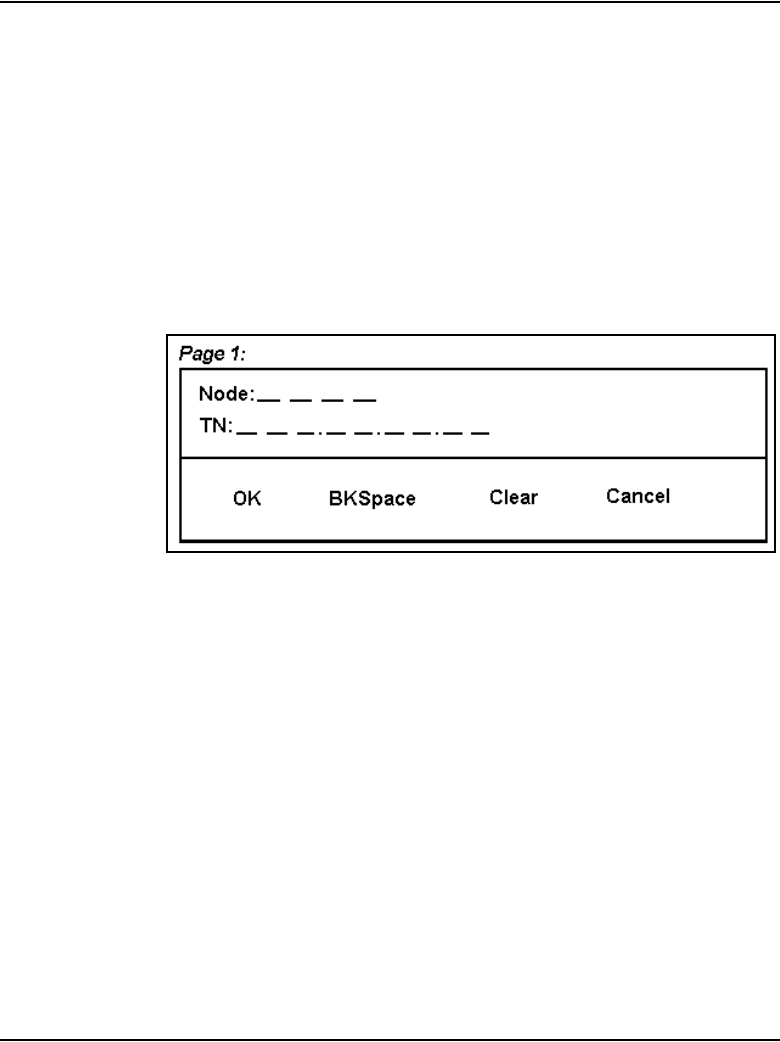
Page 546 of 910 IP Line 4.5 administration
553-3001-365 Standard 4.00 August 2005
Registration screens with TN password feature
The following screens shows the existing TN entry screen that appears when
the IP Phone registers:
• Figure 172 displays the screen on the IP Phone 2004/IP Phone 2007 if
password protection is disabled or not configured.
• Figure 173 on page 547 displays the screen on the IP Phone 2001/IP
Phone 2002/ IP Audio Conference Phone 2033 if password protection is
disabled or not configured.
Figure 172
IP Phone 2004/IP Phone 2007 registration with no password checking
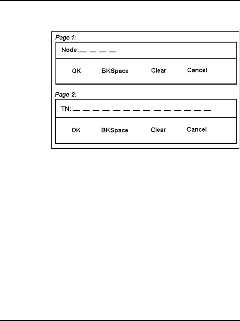
IP Line 4.5 administration Page 547 of 910
IP Line Description, Installation and Maintenance
Figure 173
IP Phone 2001/IP Phone 2002/IP Audio Conference Phone 2033
registration with no password checking

Page 548 of 910 IP Line 4.5 administration
553-3001-365 Standard 4.00 August 2005
When the TN password protection feature is configured with a non-zero
length password and is enabled:
• Figure 174 on page 549 shows the IP Phone 2004 /IP Phone 2007 TN
entry screens.
— Figure 174 on page 549 displays the Node ID and Password. Note
the Password entry input field is blank (underscores are not
displayed). Therefore, the maximum length of the password is not
disclosed.
— If the correct password is entered, the TN is displayed.
• Figure 175 on page 550 shows the IP Phone 2001/IP Phone 2002/IP
Audio Conference Phone 2033 TN entry screens.
— Figure 175 displays the Node ID. The Node ID is entered and the
user presses OK.
— Figure 175 displays the Password entry window. Note the Password
entry input field is blank (underscores are not displayed). Therefore,
the maximum length of the password is not disclosed.
— If the correct password is entered, the TN is displayed.
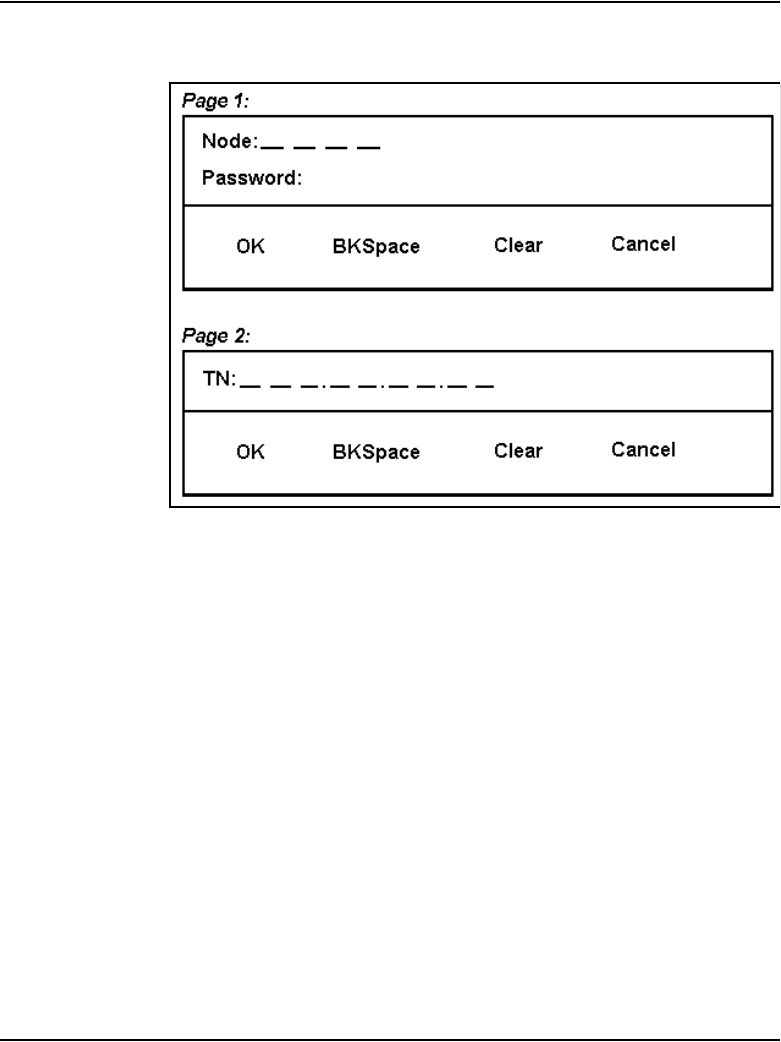
IP Line 4.5 administration Page 549 of 910
IP Line Description, Installation and Maintenance
Figure 174
IP Phone 2004/ IP Phone 2007 registration with password checking
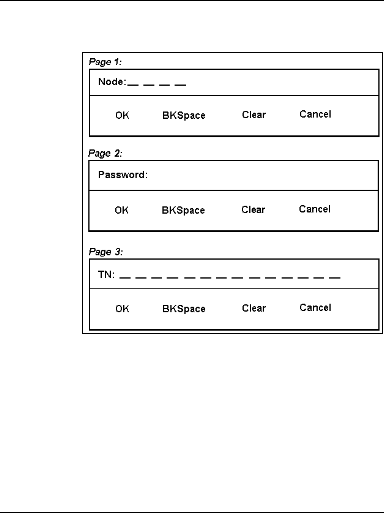
Page 550 of 910 IP Line 4.5 administration
553-3001-365 Standard 4.00 August 2005
Figure 175
IP Phone 2001/IP Phone 2002/IP Audio Conference Phone 2033
registration with password checking

IP Line 4.5 administration Page 551 of 910
IP Line Description, Installation and Maintenance
IP Line CLI commands for password control
The IP Phone Installer Passwords are configured on any Voice Gateway
Media Card in the node. The IP Phone Installer Password is configured and
administered using a set of six IPL> CLI commands:
• nodePwdSet “password”
• nodePwdShow
• nodePwdTempPwdSet “temppwd”, uses, <time>
• nodeTempPwdClear
• nodePwdEnable
• nodePwdDisable
The commands begin with “node” as they work at the node level. For detailed
information about these commands, see Table 94: “IP Phone Installer
Password commands” on page 723.
When an IP Telephony node is first installed, the IP Phone Installer Password
is not defined or enabled by default. To prevent users from inadvertently
re-configuring the Node ID and TN on their IP Phones, enable the IP Phone
Installer Password after the IP Phone is initially installed and the system is in
service.
Password security controls access to an IP Phone's TN for the purpose of
registering to a different virtual line TN on the Call Server after the IP Phones
have been installed. A password is not encrypted by the IP Phone or the Voice
Gateway Media Card.
By default, when a node is initially installed, the administrative password and
the temporary password are not defined, and the password feature is disabled.

Page 552 of 910 IP Line 4.5 administration
553-3001-365 Standard 4.00 August 2005
The nodePwdSet “password” command configures and enables the
password. When the password is enabled and configured, the screen on the IP
Phone displays the four digit Node ID and a Password prompt, instead of the
Node ID and TN fields.
If the nodePwdEnable command is entered before the password is set using
the nodePwdSet command, the password is also enabled with a null
(zero-length) password and as a result, the password and TN prompts are also
never displayed on the IP Phones.
The administrator normally uses the Administrative IP Phone Installer
Password if it is necessary to install a new telephone or change the
configuration (node ID and TN) of an existing telephone.
Note: If an IP Phone cannot be installed because a prompt for a node ID
and TN does not appear, log into a Voice Gateway Media Card and check
the status of the password using the nodePwdShow command.
WARNING
The nodePwdSet command with no “password”
parameter enables the administrator password and sets
a null (zero-length) password.
Enabling the administrator password and setting a null
password makes it impossible to install the IP Phones
because the Node ID and TN prompts are not displayed
on the telephone screen.
Always specify the “password” parameter when issuing
the nodePwdSet command. This password parameter is
6-14 digits. The valid characters are 0-9 * #.
IMPORTANT!
The administrator can create a temporary IP Phone Installer Password
for experienced users who are delegated to install IP Phones. If a null
administrator password is set and a temporary password is created, the
temporary password overrides the null administrator password.

IP Line 4.5 administration Page 553 of 910
IP Line Description, Installation and Maintenance
To suppress all password prompting to reconfigure the Node ID and TN, clear
the temporary password using the nodeTempPwdClear command. Also,
configure the administrative password to a null password using the
nodePwdSet command with no “password” parameter specified.
Configure the IP Phone Installer Passwords
The IP Phone Installer Passwords are configured on one Voice Gateway
Media Card or on the Signaling Server in the node. The passwords are then
applied to all cards in the node.
Administrative IP Phone Installer Password
The Administrative IP Phone Installer Password is used by the administrator
to install a new IP Phone or change the configuration (node ID and TN) of an
existing IP Phone.
To configure the Administrative IP Phone Installer Password, follow the
steps in Procedure 69.
Procedure 69
Configuring the Administrative IP Phone Installer Password
1Connect to any Voice Gateway Media Card in the node.
2Login to the IPL> CLI and type the nodePwdShow command. This
command displays the settings of the IP Phone Installer (node) password.
If in the default state, the IP Phone Installer Password has never been set.
The nodePwdShow command should display the following:
where:
NodeID – the IP Phone Installer Password configuration applies to all
Voice Gateway Media Cards on the same TLAN that belong to this Node
ID.
PwdEna – by default the cards should be in disabled state (PwdEna=No).
The PwdEna setting specifies the enabled (Yes) or disabled (No) state of
the IP Phone Installer Password.
NodeID
======
123
PwdEna
=======
No
Pwd
========
TmpPwd
========
Uses
=======
Timeout
===========
0d 0h 0m 0s

Page 554 of 910 IP Line 4.5 administration
553-3001-365 Standard 4.00 August 2005
Pwd – this is the Administrator IP Phone Installer Password. In the default
state, the Administrator password is null (zero-length).
TmpPwd – this is the temporary IP Phone Installer Password. In the
default state, the temporary password is null.
Uses – the Uses parameter applies to the temporary IP Phone Installer
Password. In the default state, this setting is null. If the card is not in the
default state, the Uses parameter is a numeric value from 0 –1000. This
number specifies the remaining number of uses for the temporary
password. If zero is entered for the Uses parameter when setting the
temporary password, the Time parameter is mandatory. When the Time
parameter is in effect, the password expiration is based on time instead
of the number of uses.
Timeout – the Timeout heading corresponds to the Time parameter of the
temporary IP Phone Installer Password. In the default state, the Time is
null. If the card is not in the default state, this setting specifies the duration
in hours in which the temporary password is valid. The range is 0 – 240
hours (which is a maximum of 10 days). The number specified under
Timeout indicates the remaining time to expire of the temporary
password. The Time parameter is optional if the Uses parameter is
non-zero. The Time parameter is mandatory if the Uses parameter is set
to zero.
Note: If both the Uses and Time parameters are entered, the password
expires based on whichever happens first; that is, the number of Uses is
reduced to zero or the Time has expired. If both the Uses and Time
parameters are entered and are set to zero, it is the same as not
configuring the temporary password.
3Configure the Administrator IP Phone Installer Password.
The nodePwdSet <“password”> command enables and configures the
administrator password. The <password> parameter can be null, or 6 to
14 digits in length. The valid characters are 0-9 * #. This command can be
entered at any time. The new password entered simply overwrites the
previous password.
Configure the password, first with a null password and then with a
password specified.
4Type nodePwdSet at the IPL> prompt.
Note that no password parameter is specified.
IP Line 4.5 administration Page 555 of 910
IP Line Description, Installation and Maintenance
Type nodePwdShow to see the following:
PwdEna – the password is now enabled (PwdEna=Yes).
Pwd – if no <“password”> parameter specified, the administrator
password is null. IP Phones cannot be installed when the password is
null. A null password causes the node ID and Password screen to be
skipped during restart.
5Type nodePwdSet <“password”> at the IPL> prompt, where the
password parameter is 6 to 14 digits in length.
The valid character are 0-9 * #. For this example, use “1234567” as the
password.
6Type nodePwdShow to see the following:
PwdEna – the administrator password is enabled (PwdEna=Yes).
Pwd – the administrator password, 1234567, is displayed.
Note: Always specify the <password> parameter when entering the
nodePwdSet command.
NodeID
======
123
PwdEna
=======
Ye s
Pwd
========
TmpPwd
========
Uses
=======
Timeout
===========
0d 0h 0m 0s
WARNING
The nodePwdSet command, with no parameter, by
default enables the administrator password and sets a
null (zero-length) password.
IP Phones cannot be installed if the administrator
password is enabled and set to null.
Always specify the password parameter to install IP
Phones.
NodeID
======
123
PwdEna
=======
Ye s
Pwd
========
1234567
TmpPwd
========
Uses
=======
Timeout
===========
0d 0h 0m 0s

Page 556 of 910 IP Line 4.5 administration
553-3001-365 Standard 4.00 August 2005
The nodePwdEnable and nodePwdDisable commands enable and
disable the administrative IP Phone Installer Password, respectively.
End of Procedure
Temporary IP Phone Installer Password
A temporary IP Phone Installer Password can be configured. This enables
temporary user access to the TN for configuration. A temporary password
removes the need to distribute the administrative (node) password and then
the need to change it afterwards. If there is a null administrator password
configured and a temporary password is created, the temporary password
overrides the null administrative password.
The syntax for temporary IP Phone Installer Password specifies:
• the password
• the number of times that the password can be entered
• the time that the password is valid
To configure a temporary IP Phone Installer Password, follow the steps in
Procedure 70.
Procedure 70
Configuring the temporary IP Phone Installer Password
1Type nodeTempPwdSet <“password”>, <uses>, <time> at the IPL>
prompt, where “password” is the temporary password string 6 to 14 digits
in length, uses is the value from 0 to 1000, and time is between 0 and 240
hours.
For example, nodeTempPwdSet “987654”, 15, 3
2Type nodePwdShow to see the following:
NodeID
======
123
PwdEna
=======
Ye s
Pwd
========
1234567
TmpPwd
========
987654
Uses
=======
15
Timeout
===========
0d 3h 0m 0s

IP Line 4.5 administration Page 557 of 910
IP Line Description, Installation and Maintenance
The temporary password is automatically deleted after it has been used
the defined number of times (Uses) or when the duration expires
(Timeout), whichever comes first. However, to delete the temporary
password before the number of uses or time has expired, type the
nodeTempPwdClear command at the IPL> prompt.
3Type nodePwdShow to verify that the temporary password has been
deleted.:
End of Procedure
Default user name and password
The IPL> CLI has a default user name of itgadmin and a default password of
itgadmin. The default user name and password must be changed as a
preventative security measure. The shellPasswordSet command changes the
IP Line username and password.
Reset the IPL> CLI Shell user name and password
If the authorized system management personnel do not have the current IPL>
CLI Shell user name and password, reset the user name and password to the
default (itgadmin and itgadmin).
To reset the IPL> CLI shell user name and password, follow the steps in
Procedure 71 on page 558. This procedure requires a connection to the local
maintenance port on the Voice Gateway Media Card and also requires
rebooting the card, which interrupts services.
NodeID
======
123
PwdEna
=======
Ye s
Pwd
========
1234567
TmpPwd
========
Uses
=======
Timeout
===========
0d 0h 0m 0s
Page 558 of 910 IP Line 4.5 administration
553-3001-365 Standard 4.00 August 2005
Procedure 71
Resetting the user name and password to default
1Connect a terminal to the Maintenance port (labeled Maint) either directly
or through a dial-up modem. The terminal communication parameters
must be as follows:
• 9600bp
• 8 data bits
• no parity
• 1 stop bit
2Press the Enter key on the keyboard.
The IPL> prompt is displayed.
3Reboot the card by pressing the RESET button on the faceplate of the
card with a pointed object, such as a ball-point pen.
4Start up messages are displayed on the terminal. Type jkl on the terminal
keyboard when the prompt is displayed.
Note: jkl runs from BIOS or boot ROM which is printed early in the
bootup process. There is only a six second window at the prompt to enter
jkl. If the prompt is missed, restart the card and repeat the above step.
5Once the card has booted from BIOS or boot ROM, a CLI prompt such as
the BIOS> appears. Enter the following command:
shellPasswordNvramClear at the prompt.
6Type reboot at the prompt to reboot the card.
7Wait for the card to completely reboot into the IP Line 4.5 application.
The password synchronization feature changes the password on the card
automatically.
End of Procedure
WARNING
Do not use a pencil to reset the Voice Gateway Media
Card. The graphite carbon can create an electrical short
circuit on the board.

IP Line 4.5 administration Page 559 of 910
IP Line Description, Installation and Maintenance
IP configuration commands
Table 76 describes the IP configuration commands.
TLAN network interface configuration commands
Auto-negotiate mode can be disabled if the ports on some data network
switches and routers are manually configured. For example, configuring a
port for 100BaseT full-duplex can disable auto-negotiation on the signaling
link.
The Voice Gateway Media Card and the IP Phone default to half-duplex
mode when no auto-negotiation signaling occurs. The result is that the Voice
Gateway Media Card and the IP Phone operate in half-duplex mode, while the
switch is in full-duplex mode. Communication continues, but random packet
loss can occur which affects the correct operation and voice quality.
Table 76
IP configuration commands
IP configuration
command
Function
setLeader Performs all the necessary actions to make a
Leader. Sets IP address, gateway, subnet mask,
boot method to static, and Leader bit in NVRAM.
clearLeader Clears the Leader info in NVRAM and sets the
boot method to use BOOTP, thus, making the
card a Follower.
NVRIPShow Prints the values of the IP parameters that reside
in NVRAM.
IMPORTANT!
Configure ports for auto-negotiation, auto-sense.

Page 560 of 910 IP Line 4.5 administration
553-3001-365 Standard 4.00 August 2005
Configure the speed and duplex setting of the TLAN network interface using
the following commands:
•tLanSpeedSet speed – this command configures the speed of the TLAN
network interface. By default, the network interface auto-negotiates to
the highest speed supported by the switch. If the switch is 10/100BaseT,
the network interface negotiates to 100BaseT. Use this command to
debug Ethernet speed-related problems by forcing the network interface
to 10BaseT operation immediately. The duplex mode setting is saved in
NVRAM and read at start-up. The parameter speed is set to the
following:
10 – disables auto-negotiation and sets speed to 10 Mbps
10100 – enables auto-negotiation
•tLanDuplexSet duplexMode – this command immediately configures
the duplex mode of the TLAN network interface while operating when
auto-negotiate is disabled and speed has been fixed to 10 Mbps (or
10BaseT mode). The duplex mode is saved in NVRAM and read at
start-up. The parameter duplexMode is set to the following:
0 – enables full-duplex mode
1 – enables half-duplex mode
If the auto-negotiation is disabled, and the speed and duplex mode are forced
using the CLI commands, Nortel recommends that half-duplex mode be used
to inter-operate with the far end when the far end is set to auto-negotiate.
If the duplex mode is configured as full-duplex, the far end must be
configured as full-duplex and auto-negotiate must be turned off.
Half-duplex mode works with either half-duplex or auto-negotiate at the far
end. However, full-duplex at the near end only operates with full-duplex at
the far end.
For the IP Line 4.5 application, half-duplex has ample bandwidth for a Voice
Gateway Media Card even with 24 busy channels, VAD disabled, and G.711
codec with 10 Mbps voice payload size.

IP Line 4.5 administration Page 561 of 910
IP Line Description, Installation and Maintenance
Display the number of DSPs
The DSPNumShow command displays the number of DSPs on the Voice
Gateway Media Card.
At the IPL> prompt, type: DSPNumShow.
Display IP Telephony node properties
The IPInfoShow command displays information about an IP Telephony
node.
At the IPL> prompt, type: IPInfoShow
The following IP Telephony node information is displayed on the TTY:
• IP addresses for the ELAN and TLAN subnets
• default router for the ELAN and TLAN subnets
• subnet mask for the ELAN and TLAN subnets
• SNMP manager
• IP routing table
• IP configuration of the card (which is related to the IP configuration of
the node)

Page 562 of 910 IP Line 4.5 administration
553-3001-365 Standard 4.00 August 2005
The IPInfoShow command displays information similar to the following:
Maintenance Interface = lnIsa0
Maintenance IP address = 47.103.220.199
Maintenance subnet mask = 255.255.255.224
Voice Interface = lnPci1
Voice IP address = 47.103.247.221
Voice subnet mask = 255.255.255.0
ROUTE NET TABLE
ROUTE HOST TABLE
value = 77 = 0x4d = 'M'
destination gateway flags Refcnt Use Interface
0.0.0.0 47.103.247.1 3 7 5800883 lnPci1
47.103.220.192 47.103.220.199 101 0 0 lnIsa0
47.103.247.0 47.103.247.221 101 0 0 lnPci1
47.103.247.0 47.103.247.221 101 0 0 lnPci1
destination gateway flags Refcnt Use Interface
127.0.0.1 127.0.0.1 5 0 0 lo0

IP Line 4.5 administration Page 563 of 910
IP Line Description, Installation and Maintenance
Display Voice Gateway Media Card parameters
The following commands provide information about a Voice Gateway Media
Card:
• itgCardShow
•ifShow
• serialNumShow
• firmwareVersionShow
• swVersionShow
• electShow
• tpfShow
itgCardShow
The itgCardShow command displays information about a Voice Gateway
Media Card.
At the IPL> prompt, type: itgCardShow
The itgCardShow command displays information similar to the following:
Index : 1
Type : EXUT
Role : Leader
Node : 123
Leader IP : 47.103.247.220
Card IP : 47.103.247.221
Card TN : 44 0 10
Card State : ENBL
Uptime : 1 days, 19 hours, 43 mins, 11 secs (157391
secs)
Codecs : G711Ulaw(default), G711Alaw, G729AB
lnPci stat : 100 Mbps (Carrier OK)
value = 1 = 0x1

Page 564 of 910 IP Line 4.5 administration
553-3001-365 Standard 4.00 August 2005
electShow
The electShow command shows information to help a technician quickly
become familiar with the current state of the node. The command displays a
list of cards in the node and information about each card. This includes
showing all registered followers to a leader.
The output has two sections:
• cards currently registered
• cards that are in the BOOTP.TAB configuration but not yet registered
Registered cards
The following information is displayed for each card currently registered:
• platform
•TN
• ELAN network interface MAC
• TLAN network interface IP Address
• ELAN network interface IP Address
• how long it has been registered
• how many IP Phones are registered to the card
• number of Time Outs
Unregistered cards
The following information is displayed for each card currently not yet
registered based on BOOTP.TAB:
• platform
•TN
• ELAN network interface MAC
• TLAN network interface IP Address
• ELAN network interface IP Address

IP Line 4.5 administration Page 565 of 910
IP Line Description, Installation and Maintenance
Example
The following is an example of the output on a Signaling Server:
oam> electShow
Node ID : 678
Node Master : Yes
Up Time : 1 days, 3 hours, 1 mins, 58 secs
TN : 00 00
Host Type : ISP 1100
IP TLAN : 47.11.215.55
IP ELAN : 47.11.216.139
Election Duration : 15
Wait for Result time : 35
Master Broadcast period : 30
===== master tps =====
Host Type TN TLAN IP Addr
ISP 1100 00 00 47.11.215.55
Next timeout : 3 sec
AutoAnnounce : 1
Timer duration : 60 (Next timeout in 17 sec)
====== all tps ======
Num TN Host Type ELAN MAC TLAN IP Addr ELAN IP Addr
Up Time NumOfSets TimeOut
001 00 00 ISP 1100 00:02:B3:C5:50:C2 47.11.215.55
47.11.216.139 001 03:01:58 5 0
002 03 00 ITG-P 00:60:38:8E:71:5C 47.11.215.37
47.11.217.157 006 05:30:13 0 0
====== Cards in node configuration that are not
registered ======
Num TN Host Type ELAN MAC TLAN IP Addr ELAN IP Addr
001 7 0 SMC 00:60:38:BD:C1:C1 47.11.215.54
47.11.216.49
value = 27886252 = 0x1a982ac

Page 566 of 910 IP Line 4.5 administration
553-3001-365 Standard 4.00 August 2005
When all cards configured in a node are registered, the last part of the output
displays the following:
====== All cards in node configuration are
registered ======
tpsShow
The following is an example of the output from the tpsShow command for an
ITG-P 24-port line card.
IPL> tpsShow
Node ID : 0
Is master : 1
Up time : 4 days, 2 hours, 40 mins, 53 secs (355253
secs)
TN : 03-00
Platform : ITG Pentium
TPS Service : Yes
IP TLAN : 192.168.1.140
IP ELAN : 192.168.1.14
ELAN Link : Up
Sets Connected: 4
Sets Reserved : 0
value = 18 = 0x12
Packet loss monitor
Monitor audio packet loss using the following commands:
•vgwPLLog 0|1|2 – enables the packet loss monitor. Packet loss is
measured in the receive direction and the two halves of a call are
monitored and logged independently.
— A value of zero (0) disables packet loss logging.
— A value of one (1 – default) logs a message if packet loss during the
course of the call exceeds the threshold set with the itgPLThreshold
command.

IP Line 4.5 administration Page 567 of 910
IP Line Description, Installation and Maintenance
— A value of two (2) indicates that log messages are printed as packet
loss is detected during the call. A message is printed each time
packet loss is detected indicating how many packets where lost at
that moment.
•itgPLThreshold xxx – this command sets the packet loss logging and
alarm threshold, where xxx is a number between 1 and 1000, and
represents the threshold in 0.1% increments. Packet loss which exceeds
the threshold generates an SNMP trap and writes a message to the log file
if logging is enabled. The default value is 10 (1%).
Transfer files using the CLI
A number of special file transfer commands are available to Put/Get files
from the IPL> CLI. These commands are normally used as part of an expert
support procedure if OTM or Element Manager are not available.
These commands, listed in Table 77, are from the perspective of the Voice
Gateway Media Card. If “Get” is part of the command, the file is transferred
from the OTM PC to the Voice Gateway Media Card. If “Put” is part of the
command, the file is transferred from the Voice Gateway Media Card to the
OTM PC.
To transfer a file, enter one of the commands in listed in Table 77 at the IPL>
CLI, depending on what type of file transfer is to occur.
Table 77 lists the commands can be entered at the IPL> CLI.
Table 77
IPL> CLI Commands – file transfer (Part 1 of 2)
Command Parameters
swDownload <hostname> <username> <password> <directory path> <filename>
configFileGet <hostname> <username> <password> <directory path> <filename>
bootPFileGet <hostname> <username> <password> <directory path> <filename>
hostFileGet <hostname> <username> <password> <directory path> <filename>
<ITGFileName> <listener>

Page 568 of 910 IP Line 4.5 administration
553-3001-365 Standard 4.00 August 2005
Note 1: These commands are case-sensitive. The parameters following
the command must each be enclosed in quotation marks, and there must
be a comma and no spaces between the parameters.
Note 2: For a complete description of these commands, see
Table 88: “File Transfer commands” on page 715.
Note 3: Hostname refers to any of the following:
– the IP address of the FTP host
– the Voice Gateway Media Card itself (use loopback address
127.0.0.1)
– another Voice Gateway Media Card
bootPFilePut <hostname> <username> <password> <directory path> <filename>
currOMFilePut <hostname> <username> <password> <directory path> <filename>
prevOMFilePut <hostname> <username> <password> <directory path> <filename>
logFilePut <hostname> <username> <password> <directory path> <filename>
configFilePut <hostname> <username> <password> <directory path> <filename>
hostFilePut <hostname> <username> <password> <directory path> <filename>
<ITGFileName>
Table 77
IPL> CLI Commands – file transfer (Part 2 of 2)

IP Line 4.5 administration Page 569 of 910
IP Line Description, Installation and Maintenance
Download the IP Line 4.5 error log
The IP Line 4.5 error log contains error conditions as well as normal events.
Some error conditions can be severe enough to raise an alarm through SNMP
traps.
Use the LogFilePut command to download an IP Line 4.5 error log.
Reset the Operational Measurements file
Reset the Operational Measurements (OM) file if incorrect statistics might
have been collected.
At the IPL> prompt, type: resetOM.
The resetOM command resets all operational measurement parameters that
have been collected since the last log dump. The statistics start from zero.

Page 570 of 910 IP Line 4.5 administration
553-3001-365 Standard 4.00 August 2005

Page 571 of 910
IP Line Description, Installation and Maintenance
634
IP Line administration using
Element Manager
Contents
This section contains information on the following topics:
Introduction . . . . . . . . . . . . . . . . . . . . . . . . . . . . . . . . . . . . . . . . . . . . . . 572
Element Manager administration procedures . . . . . . . . . . . . . . . . . . . . 572
Turn off browser caching . . . . . . . . . . . . . . . . . . . . . . . . . . . . . . . . . 572
IP Line Operational Measurement report scheduling and generation . . . . 572
View IP Line log files. . . . . . . . . . . . . . . . . . . . . . . . . . . . . . . . . . . . 580
Backup and restore data . . . . . . . . . . . . . . . . . . . . . . . . . . . . . . . . . . . . 584
Backup . . . . . . . . . . . . . . . . . . . . . . . . . . . . . . . . . . . . . . . . . . . . . . . 584
Restore the backed up files. . . . . . . . . . . . . . . . . . . . . . . . . . . . . . . . 587
Update IP Telephony node properties. . . . . . . . . . . . . . . . . . . . . . . . . . 588
Add a Voice Gateway Media Card to the node . . . . . . . . . . . . . . . . 591
Delete a Follower Voice Gateway Media Card from the node . . . . 602
Delete the Leader Voice Gateway Media Card from the node . . . . 604
Change the IP addresses of an IP Telephony node in Element Manager . . . . . 606
Restart a Voice Gateway Media Card . . . . . . . . . . . . . . . . . . . . . . . 616
Restart all the Voice Gateway Media Cards. . . . . . . . . . . . . . . . . . . 619
Update other node properties . . . . . . . . . . . . . . . . . . . . . . . . . . . . . . . . 620
Telnet to a Voice Gateway Media Card using Virtual Terminal . . . . . 620
Check the Voice Gateway Channels . . . . . . . . . . . . . . . . . . . . . . . . . . . 623
Setting the IP Phone Installer Password . . . . . . . . . . . . . . . . . . . . . . . . 627

Page 572 of 910 IP Line administration using Element Manager
553-3001-365 Standard 4.00 August 2005
Introduction
This chapter explains how to administer IP Line 4.5 and the Voice Gateway
Media Card on CS 1000 systems using Element Manager.
Element Manager administration procedures
This section describes the administration procedures that can be performed
using Element Manager.
Turn off browser caching
Internet Explorer caching interferes with the Element Manager application, in
that users cannot see real-time changes as they occur. For this reason, Nortel
recommends that Internet Explorer’s caching be turned off prior to using
Element Manager.
Follow the steps outlined in Procedure 24 on page 365 to prevent caching of
web windows by the Internet Explorer browser.
IP Line Operational Measurement report scheduling
and generation
Operational Measurement (OM) reports provide important statistical and
traffic information and feedback to the system administrator to better
engineer the system. The information stored in the OM file applies only to the
calls routed over the IP network by way of IP Line. OM reports give a
quantitative view of system performance, such as jitter.
A single Voice Gateway Media Card’s Operational Measurements file can be
viewed directly from Element Manager. This OM report is a view of the
LTPS and Voice Gateway channel activity on that specific card. Use this
procedure to view the individual card’s information for each Voice Gateway
Media Card in the node.
The Voice Gateway Media Card OM file contains the following information:
• the number of incoming and outgoing calls
• the number of call attempts
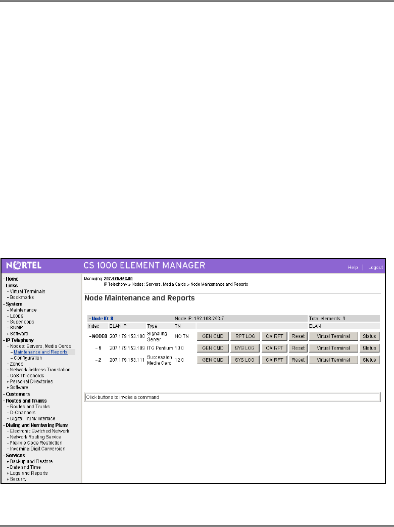
IP Line administration using Element Manager Page 573 of 910
IP Line Description, Installation and Maintenance
• the number of calls completed
• the total holding time for voice calls
To view a single Voice Gateway Media Card’s OM file directly from Element
Manager, follow the steps in Procedure 72 on page 573.
Procedure 72
Retrieving the current OM file from the Voice Gateway Media Card using
Element Manager
1In the Element Manager navigator, click IP Telephony > Nodes:
Servers, Media Cards > Maintenance and Reports.
The Node Maintenance and Reports window opens.
2Expand the node containing the Voice Gateway Media Card by clicking
the plus sign (+) to the left of the Node ID.
See Figure 176.
Figure 176
Node Maintenance and Reports window
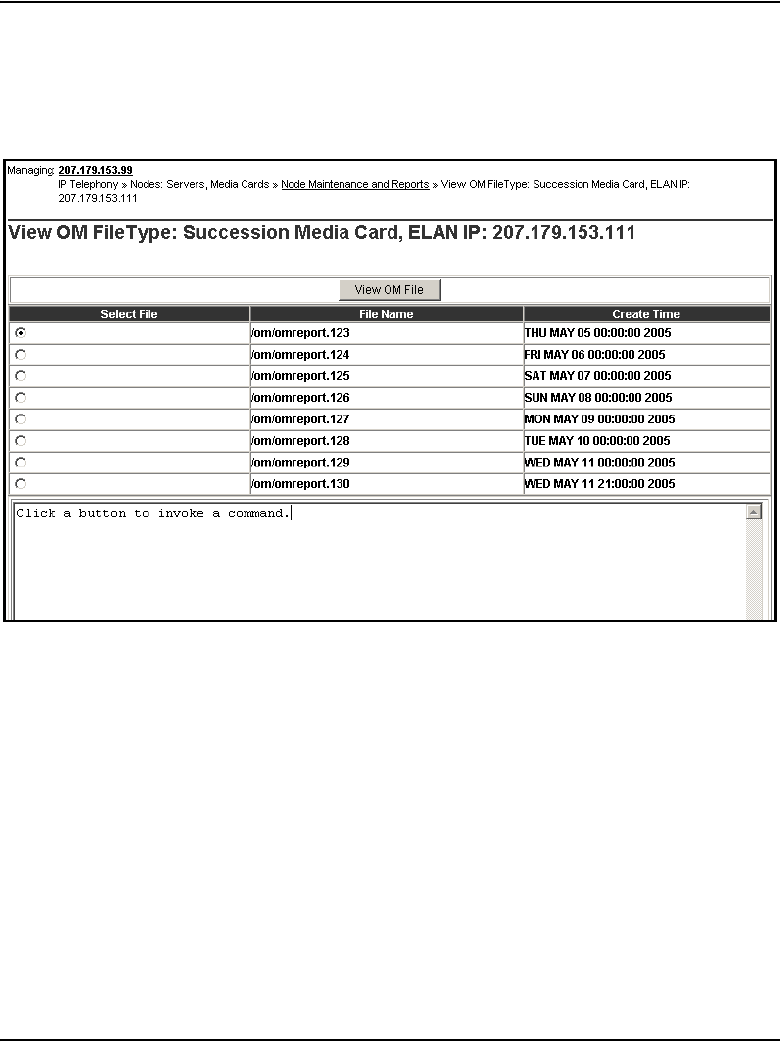
Page 574 of 910 IP Line administration using Element Manager
553-3001-365 Standard 4.00 August 2005
3Click the OM RPT button associated with the Voice Gateway Media Card.
The View OM File window opens. See Figure 177 on page 574.
Figure 177
View OM File window
The eight most recent OM Report files are displayed in chronological
order for that Voice Gateway Media Card.
4To view a OM file, click the radio button for the file to be viewed and then
click View OM File.
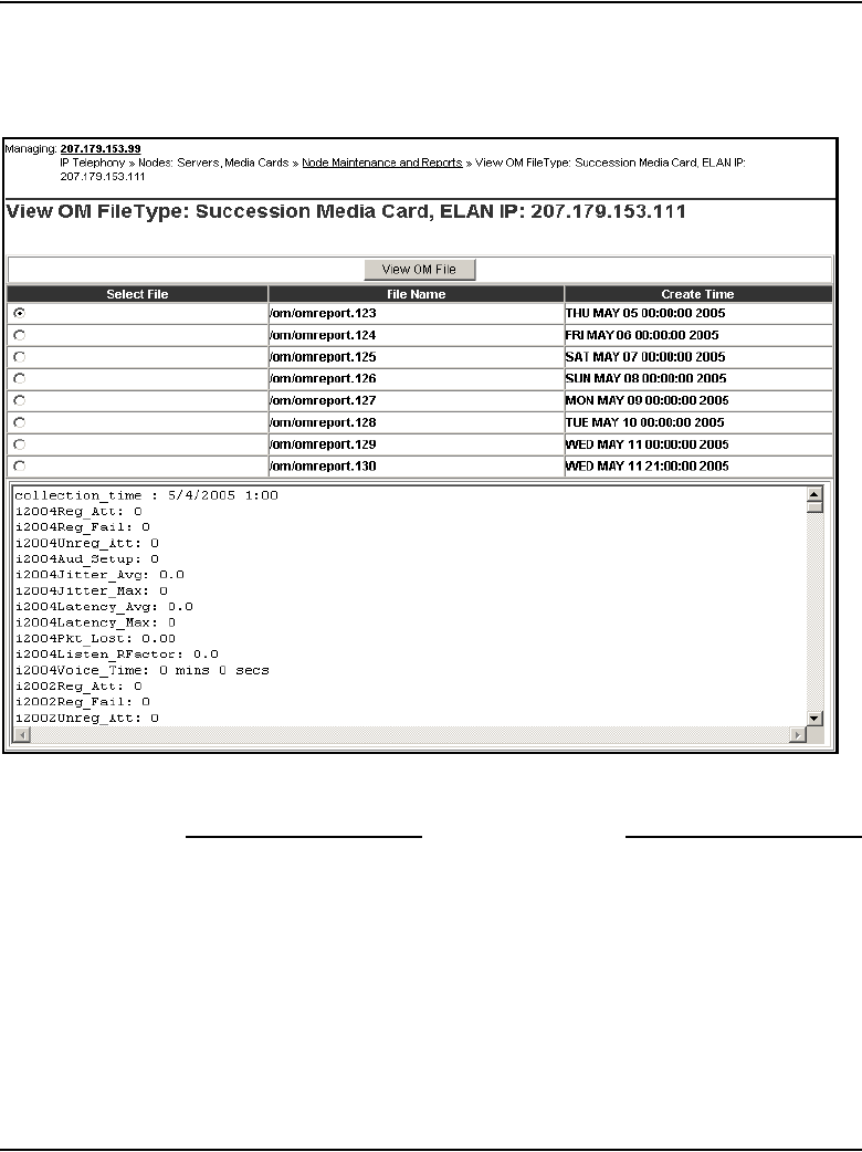
IP Line administration using Element Manager Page 575 of 910
IP Line Description, Installation and Maintenance
The OM report data appears at the bottom of the window. See Figure 178.
Figure 178
OM Report data output
End of Procedure
Collection period
The file contains collection period information for each hour of the day that
the card was running.
The collection periods start with the hour from midnight to 1:00 am. As each
hour passes, a collection period is added to the OM file; therefore, there is a
maximum of 24 collection periods each day.

Page 576 of 910 IP Line administration using Element Manager
553-3001-365 Standard 4.00 August 2005
Output
The OM report output tracks the statistics for each IP Phone type.
Data is first output for the Nortel versions of the set types i2001, i2002, i2004,
and i2050.
Note: The i2050 set type refers to both the IP Softphone 2050 and the
MVC 2050.
That output is followed by data for the 3rd-party IP Phones, labelled:
• 3Pi2001
• 3Pi2002
• 3Pi2004
• 3Pi2050
Finally, the data for the gateway channels is output.

IP Line administration using Element Manager Page 577 of 910
IP Line Description, Installation and Maintenance
Output example
An example of a single hour’s OM report is as follows:
-> ommShow
collection_time : 9/5/2003 1:00
i2004Reg_Att: 0
i2004Reg_Fail: 0
i2004Unreg_Att: 0
i2004Aud_Setup: 0
i2004Jitter_Avg: 0.0
i2004Jitter_Max: 0
i2004Pkt_Lost: 0.00
i2004Voice_Time: 0 mins 0 secs
i2002Reg_Att: 0
i2002Reg_Fail: 0
i2002Unreg_Att: 0
i2002Aud_Setup: 0
i2002Jitter_Avg: 0.0
i2002Jitter_Max: 0
i2002Pkt_Lost: 0.00
i2002Voice_Time: 0 mins 0 secs
i2001Reg_Att: 0
i2001Reg_Fail: 0
i2001Unreg_Att: 0
i2001Aud_Setup: 0
i2001Jitter_Avg: 0.0
i2001Jitter_Max: 0
i2001Pkt_Lost: 0.00
i2001Voice_Time: 0 mins 0 secs

Page 578 of 910 IP Line administration using Element Manager
553-3001-365 Standard 4.00 August 2005
i2050Reg_Att: 0
i2050Reg_Fail: 0
i2050Unreg_Att: 0
i2050Aud_Setup: 0
i2050Jitter_Avg: 0.0
i2050Jitter_Max: 0
i2050Pkt_Lost: 0.00
i2050Voice_Time: 0 mins 0 secs
3Pi2004Reg_Att: 0
3Pi2004Reg_Fail: 0
3Pi2004Unreg_Att: 0
3Pi2004Aud_Setup: 0
3Pi2004Jitter_Avg: 0.0
3Pi2004Jitter_Max: 0
3Pi2004Pkt_Lost: 0.00
3Pi2004Voice_Time: 0 mins 0 secs
3Pi2002Reg_Att: 0
3Pi2002Reg_Fail: 0
3Pi2002Unreg_Att: 0
3Pi2002Aud_Setup: 0
3Pi2002Jitter_Avg: 0.0
3Pi2002Jitter_Max: 0
3Pi2002Pkt_Lost: 0.00
3Pi2002Voice_Time: 0 mins 0 secs
3Pi2001Reg_Att: 0
3Pi2001Reg_Fail: 0
3Pi2001Unreg_Att: 0
3Pi2001Aud_Setup: 0

IP Line administration using Element Manager Page 579 of 910
IP Line Description, Installation and Maintenance
3Pi2001Jitter_Avg: 0.0
3Pi2001Jitter_Max: 0
3Pi2001Pkt_Lost: 0.00
3Pi2001Voice_Time: 0 mins 0 secs
3Pi2050Reg_Att: 0
3Pi2050Reg_Fail: 0
3Pi2050Unreg_Att: 0
3Pi2050Aud_Setup: 0
3Pi2050Jitter_Avg: 0.0
3Pi2050Jitter_Max: 0
3Pi2050Pkt_Lost: 0.00
3Pi2050Voice_Time: 0 mins 0 secs
ChanAud_Setup: 0
ChanJitter_Avg: 0.0
ChanJitter_Max: 0
ChanPkt_Lost: 0.00
ChanVoice_Time: 0 mins 0 secs
Each collection period provides the following information:
• The date and time for the collection period hour.
• LTPS information for IP Phones that are registered to the LTPS on the
Voice Gateway Media Card during that hour. During normal operation,
the LTPS values for the Voice Gateway Media Card can be zeros as the
IP Phones normally register to the LTPS on the Signaling Server.
• Voice Gateway channel information accumulated during the hour. The
Voice Gateway data is prefixed by Chan.
• Notes indicating whether the machine has been rebooted during the hour.
• Virtual Trunk statistics display only for a Signaling Server that has been
running the VTRK H.323 Signaling Server in the last hour.

Page 580 of 910 IP Line administration using Element Manager
553-3001-365 Standard 4.00 August 2005
The OM file relates to the omreport.xxx file on the Voice Gateway Media
Card, where xxx indicates the numbers of days since December 31.
In general, no relationship exists between the IP Phones registered on a Voice
Gateway Media Card and the Voice Gateway channels on the card (if two or
more cards are used) in the node. If only one Voice Gateway Media Card is
used (with multiple IP Phones), a partial correlation might exist between the
IP Phones and the card information. However, even with only one Voice
Gateway Media Card, there still is not a 100% correlation, as an IP Phone can
still call another IP Phone without involving the Voice Gateway channels.
Note: Element Manager supports the ability to view OM files only.
OTM can optionally be used to support other Operational Measurements
tasks such as scheduling reports, generating reports, opening reports, and
viewing reports.
See “Operational Measurement report scheduling and generation” on
page 636 for more information.
View IP Line log files
Element Manager uses RPC to transfer the sysfile from the Voice Gateway
Media Card to the PC. The error log file displays error information, including
error date/time, the originating module (IP Telephony node), and specific
error data.
To view error conditions that are abnormal events, but not severe enough to
raise an alarm, follow the steps in Procedure 73.
Procedure 73
Viewing IP Line log files
1In the Element Manager navigator, click IP Telephony > Nodes:
Servers, Media Cards > Maintenance and Reports.
The Node Maintenance and Reports window opens.
2Expand the node containing the Voice Gateway Media Card by clicking
the plus sign (+) to the left of the Node ID.
See Figure 179 on page 581.
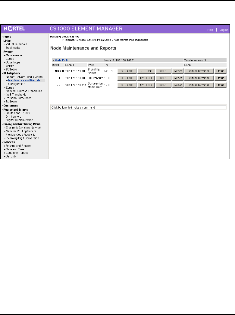
IP Line administration using Element Manager Page 581 of 910
IP Line Description, Installation and Maintenance
Figure 179
Node Maintenance and Reports window
3Click the SYS LOG button associated with the Voice Gateway Media
Card.
The Syslog window appears. See Figure 180 on page 582.
The Syslog window has five buttons to view the log files:
• The LATEST button displays the most recent syslog information for
the Voice Gateway Media Card.
• There are four SYSLOG.# buttons; one for each of the four syslog
files on the Voice Gateway Media Card.
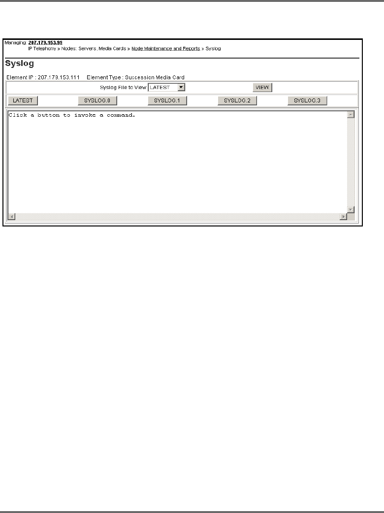
Page 582 of 910 IP Line administration using Element Manager
553-3001-365 Standard 4.00 August 2005
Figure 180
Node Maintenance and Reports > Syslog
4From the Syslog File to View drop-down list, select LATEST to view the
most current syslog information that was written to the Voice Gateway
Media Card and click View.
Alternatively, click the Latest button.
As well, SYSLOG.0, SYSLOG.1, SYSLOG.2, and SYSLOG.3 can be
selected from the drop-down list and viewed by clicking View.
Alternatively, click the SYSLOG.0, SYSLOG.1, SYSLOG.2, or
SYSLOG.3 button to view the associated syslog file.
The syslog file data is displayed in the window below the buttons. The
data can be error messages or information messages. For each
message, the date, timestamp, and the task that is printing the message
is displayed.
Figure 181 on page 583 is an example of syslog file output.
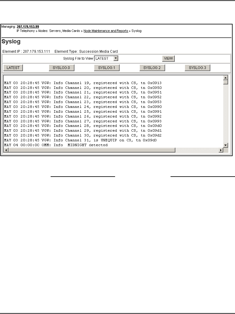
IP Line administration using Element Manager Page 583 of 910
IP Line Description, Installation and Maintenance
Figure 181
Syslog file output example
End of Procedure

Page 584 of 910 IP Line administration using Element Manager
553-3001-365 Standard 4.00 August 2005
Backup and restore data
All data is stored on the Call Server. Element Manager accesses the data for
the elements being maintained. Element Manager does not store data.
There is no Element Manager-specific data that needs to be backed up. All
data is retrieved from the Call Server and elements.
The c:/u/db/node directory is populated on the Call Server when the node
configuration is saved. The BOOTP.TAB and CONFIG.INI files are saved in
this directory as c:/u/db/node/nodexxxx.btp and c:/u/db/node/nodexxxx.cfg
where xxxx is the node ID:
• nodexxxx.btp is the BOOTP.TAB file
• nodexxxx.cfg is the CONFIG.INI.
If a node is removed, the associated files are also removed. For every node
that is created, a nodeyyyy.btp and nodeyyyy.cfg file are created in the
C:/u/db/node directory.
Backup
The Backup command invokes the Equipment Data Dump (EDD) operation
on the Call Server to back up all Call Server data. Within Element Manager,
the Call Server Backup function invokes a data dump and writes the Call
Server data to the primary and internal backup drives.
The backup includes all Call Server data as well as the BOOTP.TAB and
CONFIG.INI files for each node configured in the system. These files are
stored on the Call Server for the IP Telephony nodes configured in the
system.
This Backup function can also be performed on the Call Server by entering
the EDD CLI command using LD 43.
WARNING
Do not manually edit or delete the node files. Manually
editing or deleting these files can cause corruption of
Element Manager.
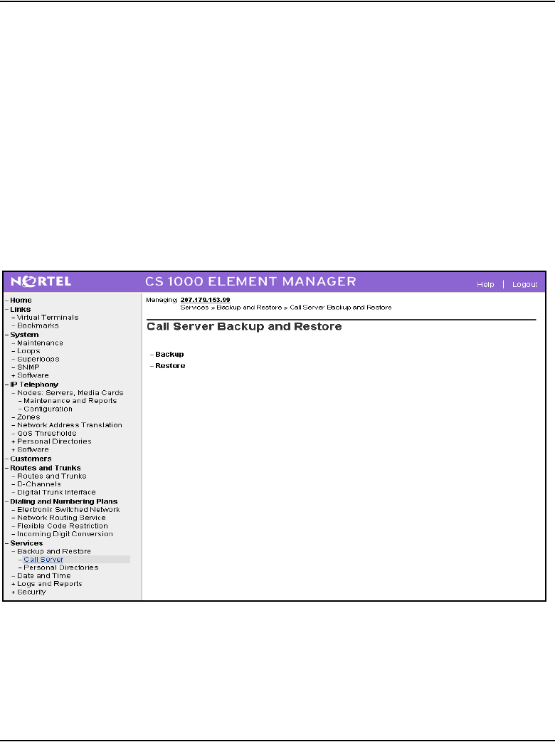
IP Line administration using Element Manager Page 585 of 910
IP Line Description, Installation and Maintenance
During the Backup function, the BOOTP.TAB and CONFIG.INI files of all
registered nodes are copied so that they can be restored in case of system
failure.
Follow the steps in Procedure 74 to back up the Call Server.
Procedure 74
Backing up the Call Server data
1In the Element Manager navigator, click Services > Backup and
Restore > Call Server.
The Call Server Backup and Restore window opens. See Figure 182.
Figure 182
Call Server Backup and Restore window
2Click Backup.
The Call Server Backup window opens. See Figure 183 on page 586.
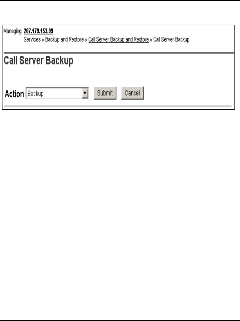
Page 586 of 910 IP Line administration using Element Manager
553-3001-365 Standard 4.00 August 2005
Figure 183
Call Server Backup window
3Select Backup from the Action drop-down list.
4Click the Submit button or click Cancel to cancel the backup.
The window displays messages indicating “Backup in progress. Please
wait...”
5Click OK in the EDD complete dialog box.
See Figure 184 on page 587.
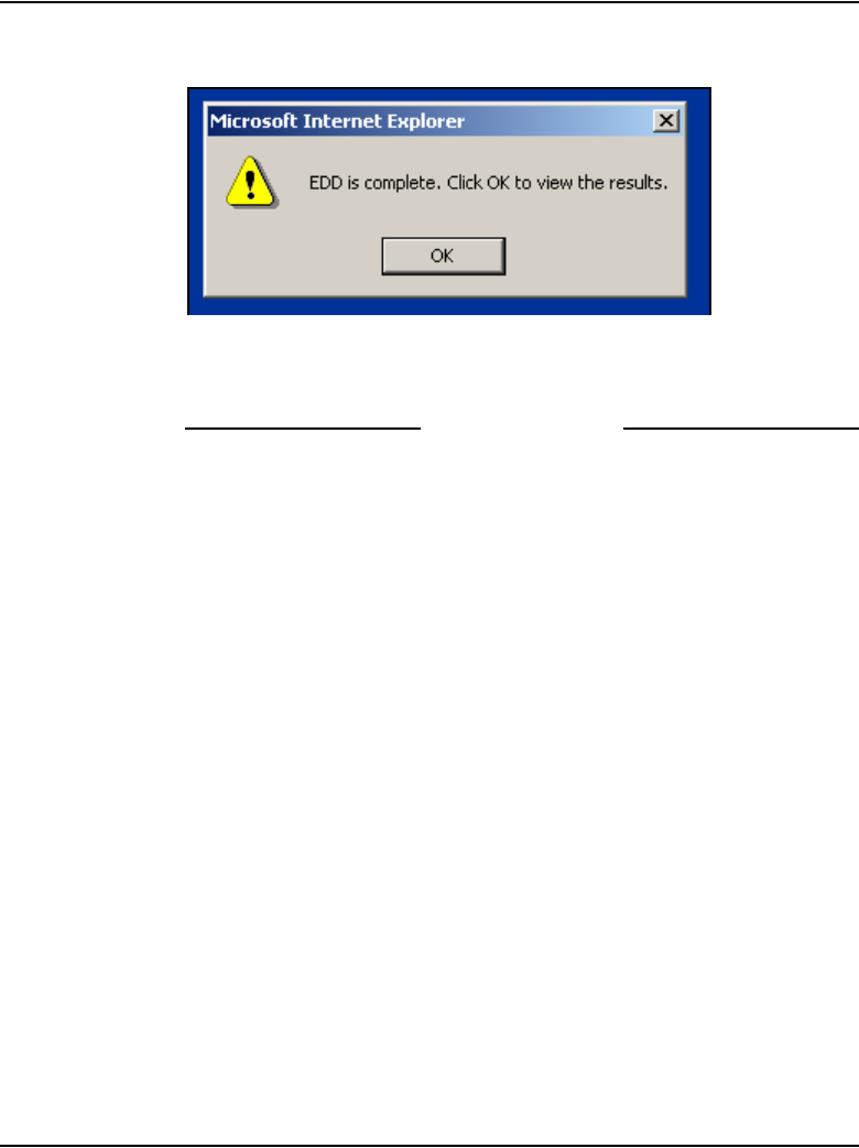
IP Line administration using Element Manager Page 587 of 910
IP Line Description, Installation and Maintenance
Figure 184
EDD complete
The Backup function then displays information in a tabular form
indicating the actions that were performed.
End of Procedure
Restore the backed up files
The Call Server Restore function restores the backed up files from the internal
backup device to the primary device. The Restore function performs the same
task as the RIB CLI command in LD 43.
To restore the Call Server data, follow the steps in Procedure 75.
Procedure 75
Restoring the Call Server data
1In the Element Manager navigator, click Services > Backup and
Restore > Call Server.
1The Call Server Backup and Restore window opens.
2Click Restore.
The Call Server Restore window opens. See Figure 185 on page 588.

Page 588 of 910 IP Line administration using Element Manager
553-3001-365 Standard 4.00 August 2005
Figure 185
System Utility > Restore
3Select Restore from Backup Data (RiB) from the Action drop-down list.
4Click the Submit button.
If the Restore is successful, the message “Restore was done
successfully” is displayed.
End of Procedure
Update IP Telephony node properties
To update the node properties of a Voice Gateway Media Card, follow the
steps in Procedure 76.
Procedure 76
Updating the IP Telephony node properties
1In the Element Manager navigator, click IP Telephony > Nodes:
Servers, Media Cards > Configuration.
The Node Configuration window opens. See Figure 186 on page 589.
2Click the Edit button associated with the node to be updated.
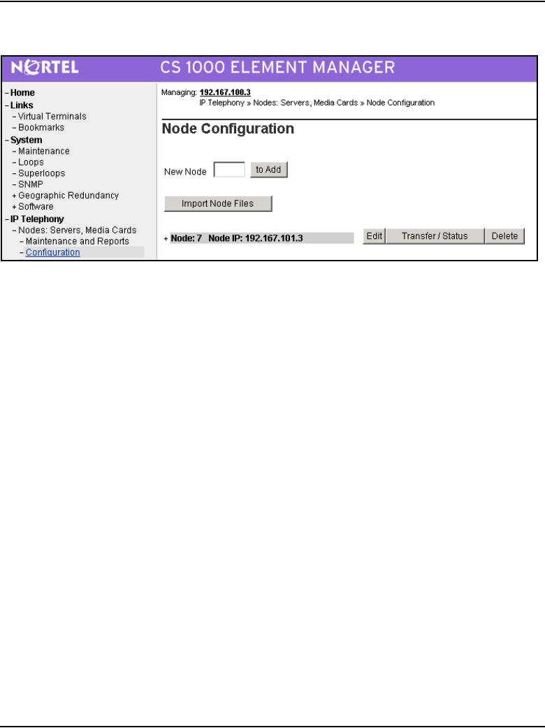
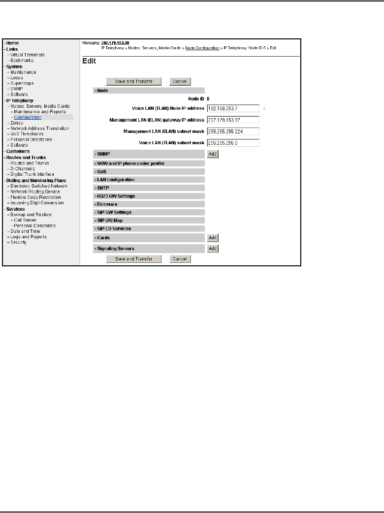
Page 590 of 910 IP Line administration using Element Manager
553-3001-365 Standard 4.00 August 2005
Figure 187
Element Manager – Edit
3Perform all required updates to the parameters in the appropriate
sections.
If Voice Gateway Media Cards are added to, deleted from, or replaced in
the node or a Voice Gateway Media Card is changed, then use one of the
following procedures:
• “Add a Voice Gateway Media Card to the node” on page 591
• “Delete a Follower Voice Gateway Media Card from the node” on
page 602
• “Change the IP addresses of an IP Telephony node in Element
Manager” on page 606
• Refer to the Maintenance chapter for the procedures to replace a
Voice Gateway Media Card. See “Replace a Leader Voice Gateway

IP Line administration using Element Manager Page 591 of 910
IP Line Description, Installation and Maintenance
Media Card” on page 775 or “Replacing a Follower Voice Gateway
Media Card” on page 772
End of Procedure
Add a Voice Gateway Media Card to the node
To add a Voice Gateway Media Card to the node, follow the steps in
Procedure 77.
Procedure 77
Adding a Voice Gateway Media Card to the node
1Choose a card slot for the new card. Note the TN.
2Configure IPTN in LD 14 at the Call Server.
3Install the I/O cables for connection to the ELAN and TLAN network
interfaces on the selected card slot.
4In the Element Manager navigator, click IP Telephony > Nodes:
Servers, Media Cards > Configuration.
The Node Configuration window opens. See Figure 188 on page 591.
Figure 188
Node Configuration window
5Click the Edit button for the node that is receiving the new Voice Gateway
Media Card.
The Edit window opens.
6Click the Add button to the right of the Cards section.

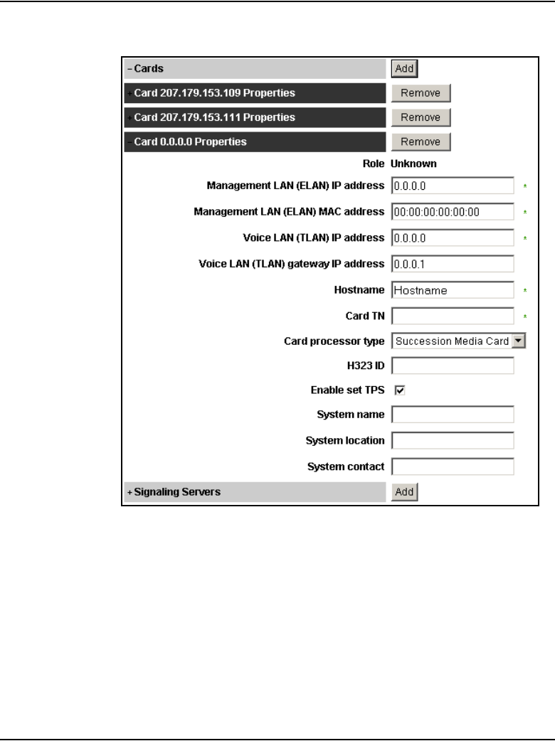
IP Line administration using Element Manager Page 593 of 910
IP Line Description, Installation and Maintenance
Figure 190
Node Configuration > Edit > Add Card
8Enter the Card Properties data:
a. Role: Element Manager reads the role from the card configuration.
b. Management LAN (ELAN) IP address: This is the ELAN network
interface IP address for the card. Element Manager and the system
use this IP address to communicate with the card.
c. Management LAN (ELAN) MAC address: This is the motherboard
Ethernet address from the “Voice Gateway Media Card installation
summary sheet” on page 307.
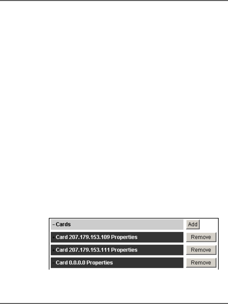
Page 594 of 910 IP Line administration using Element Manager
553-3001-365 Standard 4.00 August 2005
d. Voice LAN (TLAN) IP address: This is the TLAN network interface
IP address for the card.
e. Voice LAN gateway (TLAN) IP address: This is the IP address of
the router interface on the TLAN subnet.
f. Hostname
g. Card TN: Enter the card slot number between 1 – 50.
h. Card processor type: Choose either Pentium or Media Card from
the drop-down list. Select Pentium if using the ITG-P 24-port line card
(dual-slot card), or select Media Card if using the Media Card
single-slot card.
i. H323 ID: The H323 ID in IP Line 4.5 is for the Virtual Office/
MG 1000B feature. Keep the H323 ID the same for all the elements
within one node.
j. Enable set TPS check box: Select this check box.
k. System name: Enter the name of the system.
l. System location: Enter the location where the system resides.
m. System contact: Enter the system contact name and telephone
number.
9To add additional cards to the node, click the Add button again and enter
the new card information. Repeat this step for each card to be added to
the node.
Observe that new cards appear under the Cards section as they are
added. See Figure 191 on page 594.
Figure 191
Added cards
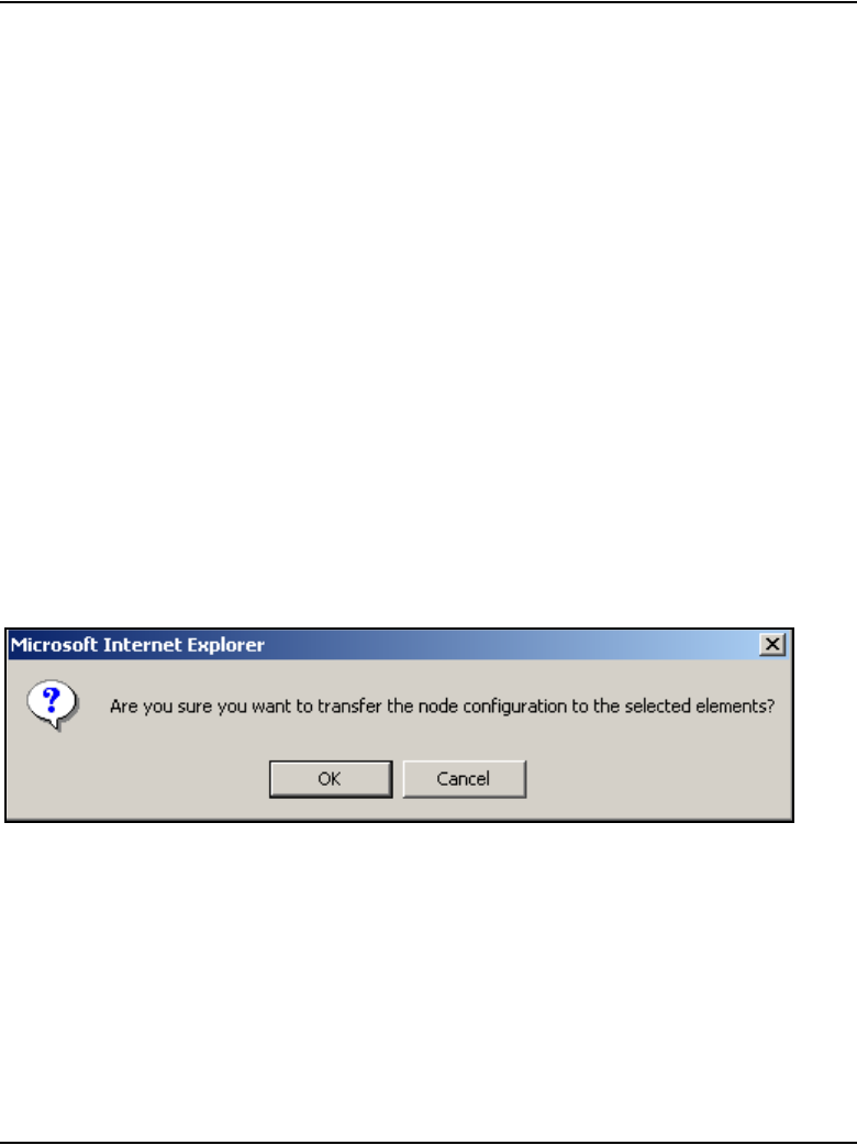
IP Line administration using Element Manager Page 595 of 910
IP Line Description, Installation and Maintenance
10 Click the Save and Transfer button after the card(s) have been added
and configured.
Clicking the Save and Transfer button saves the data to the Call Server.
11 Click OK to confirm.
Note 1: The Save and Transfer button can be clicked after each card is
configured in the Edit window. However, each time the Save and
Transfer button is clicked, the Edit window closes and the Node
Configuration window is displayed. To continue the node configuration,
click the Edit button to return to the Edit window.
Note 2: If the Cancel button is clicked, all information that has been
configured is discarded. The Edit window closes and the Node
Configuration window opens.
The Edit window closes, and the Node Configuration window opens.
12 Click the Transfer/Status button associated with the node where the new
card(s) was added.
13 Click OK to confirm the transfer.
See Figure 192.
Figure 192
Transfer confirmation dialog box
The Transfer Progress window opens and displays each of the Voice
Gateway Media Card in the node.
The Voice Gateway Media Card’s retrieve the CONFIG.INI and
BOOTP.TAB files from the Call Server. A check mark is added to each
field as the card receives its CONFIG.INI and BOOTP.TAB files.
14 When the transfer is complete, click OK in the Progress Check
Complete dialog box.

Page 596 of 910 IP Line administration using Element Manager
553-3001-365 Standard 4.00 August 2005
• If the transfer is successful for a card, the Status column displays
“Complete”.
• If the transfer is unsuccessful, the Status column displays “Fail”.
15 Insert the new card.
The card boots and obtains its IP configuration from the node master. This
process takes several minutes.
The Maintenance faceplate display shows an alarm of T:21 or S009.
• T:21 is displayed if the card is new and there is no CONFIG.INI file.
• S009 is displayed if the card has been used before and has a
CONFIG.INI file that contains an IP address for the Call Server that
is no longer correct.
16 In the Element Manager navigator, click IP Telephony > Nodes:
Servers, Media Cards > Maintenance and Reports.
The Node Maintenance and Reports window opens.
17 Expand the node containing the Voice Gateway Media Card by clicking
the plus sign (+) to the left of the Node ID.
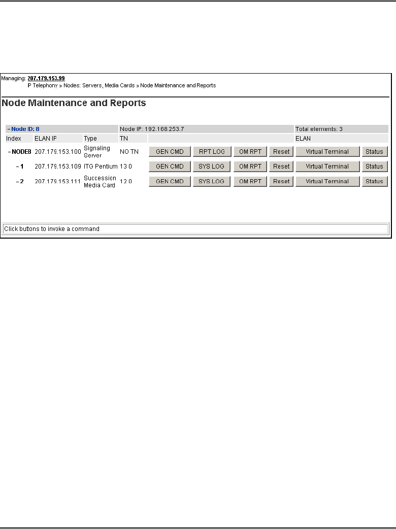
IP Line administration using Element Manager Page 597 of 910
IP Line Description, Installation and Maintenance
18 Click the GEN CMD button associated with the Voice Gateway Media
Card. See Figure 193.
Figure 193
Voice Gateway Media Card and GEN CMD button
The General Commands window opens. See Figure 194 on page 598.
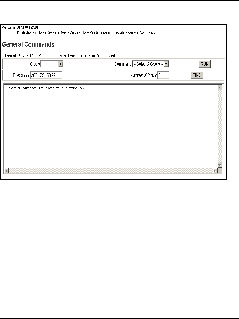
Page 598 of 910 IP Line administration using Element Manager
553-3001-365 Standard 4.00 August 2005
Figure 194
General Commands window
19 From the Group drop-down list, select Misc.
20 From the Command drop-down list, click the cardRoleShow command.
Note: If the card role is not a Follower as expected, Telnet to the card’s
IPL> CLI using Virtual Terminal, and enter the clearLeader command to
remove the clearLeader flag.
21 In the Element Manager navigator, click IP Telephony > Nodes: Servers,
Media Cards > Configuration.
The Node Configuration window opens.
22 Click the Transfer/Status button for the node.
This action downloads the node information to the card.
23 In the Element Manager navigator, click IP Telephony. Nodes: Servers,
Media Cards > Maintenance and Reports.

IP Line administration using Element Manager Page 599 of 910
IP Line Description, Installation and Maintenance
The Node Maintenance and Reports window opens.
24 Expand the node containing the new card(s) that were added by clicking
the plus sign (+) to the left of the Node ID.
25 Click the Status button for each Voice Gateway Media Card that was
added.
The card status should display as “Enabled” or “Disabled”. If the status
message of “WEB3003: Destination IP address cannot be reached; initial
RPC failure” is displayed, then verify the network connection and the
proper configuration of the network equipment.
26 Verify that all the new Voice Gateway Media Cards in the node have a
signaling link to the Call Server.
27 In the Element Manager navigator, click IP Telephony > Nodes:
Servers, Media Cards > Maintenance and Reports.
The Node Maintenance and Reports window opens.
28 Expand the node containing the Voice Gateway Media Card by clicking
the plus sign (+) to the left of the Node ID.
29 Click the GEN CMD button associated with the Voice Gateway Media
Card.
30 In the Group drop-down list, select pbxLink.
31 From the Command drop-down list, select pbxLinkShow.
See Figure 195 on page 600.
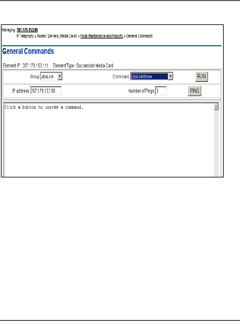
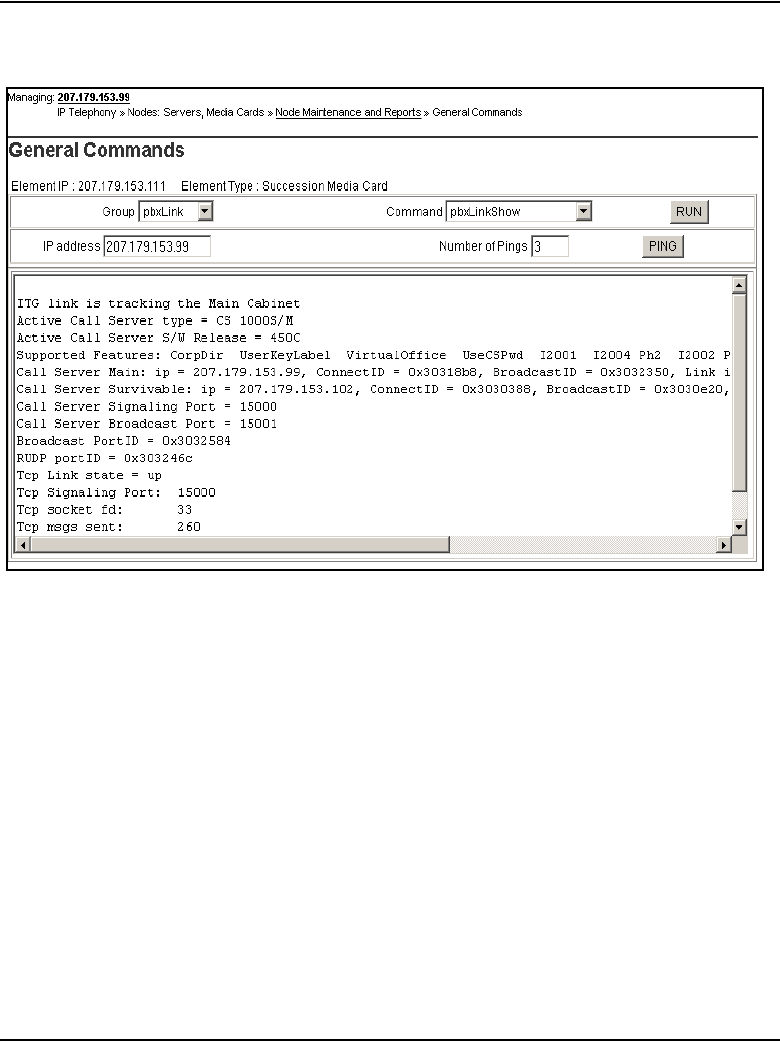
IP Line administration using Element Manager Page 601 of 910
IP Line Description, Installation and Maintenance
Figure 196
pbxLinkShow output
Note: The pbxLinkShow command can also be entered at the IPL>
command line. Telnet to each Voice Gateway Media Card and log in.
Enter the pbxLinkShow command at the IPL> prompt. Alternatively, look
at the display on the card’s faceplate and ensure it is not displaying an
alarm.
33 In the Group drop-down list of the General Commands window, select
Misc.
34 In the Command drop-down list, select cardRoleShow and click RUN.
Note: If the card role is not Follower as expected, Telnet to the card’s
IPL> CLI and enter the clearLeader command to remove the clearLeader
flag.
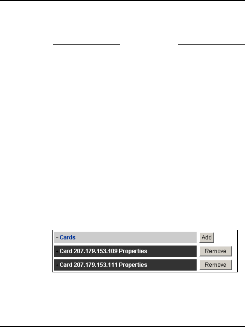
Page 602 of 910 IP Line administration using Element Manager
553-3001-365 Standard 4.00 August 2005
35 Verify the card software and firmware version on the new card and, if
necessary, upgrade the software and the firmware. Use the procedures
outlined in the section “Upgrade the Voice Gateway Media Card software
and IP Phone firmware” on page 415.
End of Procedure
Delete a Follower Voice Gateway Media Card from the node
To delete a Voice Gateway Media Card from the node, follow the steps in
Procedure 78.
Procedure 78
Deleting a follower Voice Gateway Media Card from the node
1In the Element Manager navigator, click IP Telephony > Nodes:
Servers, Media Cards > Configuration.
The Node Configuration window opens.
2Click the Edit button for the node containing the Voice Gateway Media
Card to be deleted.
The Edit window appears.
3Expand the Cards section by clicking the plus sign (+) to the left of Cards.
4Confirm the card to be deleted and then click the Remove button for that
card.
See Figure 197.
Figure 197
Edit > Remove Card
5Confirm the deletion by clicking OK. See Figure 198.
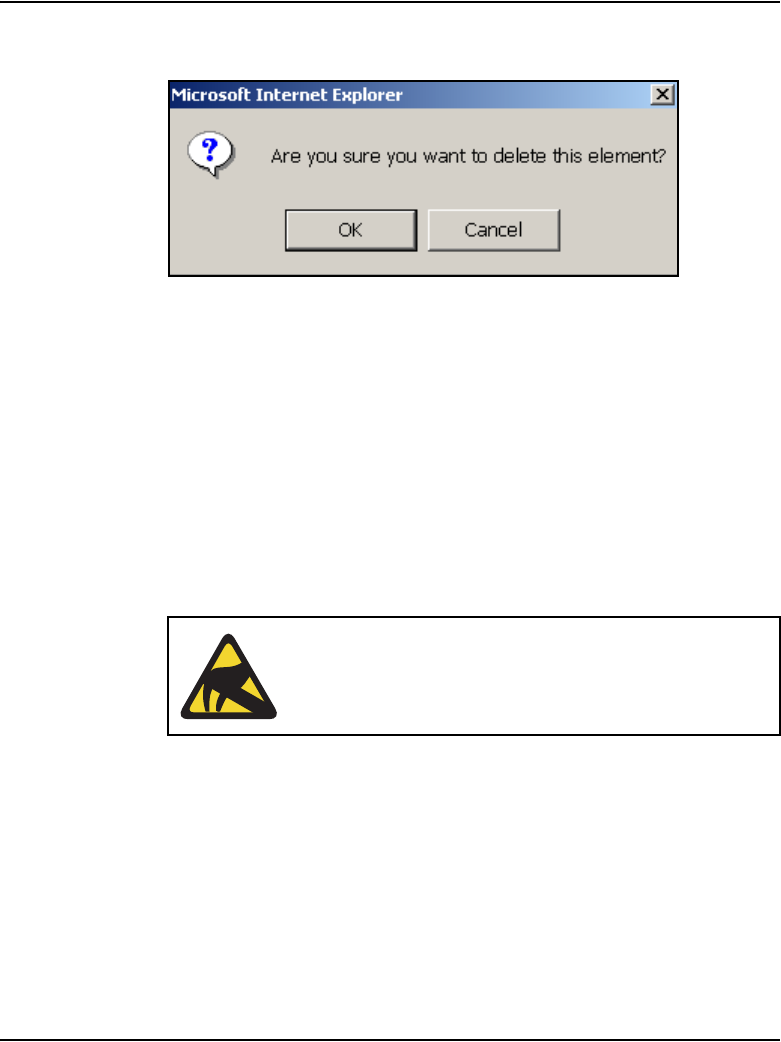
IP Line administration using Element Manager Page 603 of 910
IP Line Description, Installation and Maintenance
Figure 198
Confirm the deletion
6Click Save and Transfer to save the node change.
The Edit window closes, and the Node Configuration window opens.
7Click the Transfer/Status button associated with the node containing the
card that was removed.
8Click OK to confirm the transfer.
The Transfer Progress window opens and the changes are transferred
to the Call Server.
9Click OK in the Progress Check Complete dialog box.
10 Remove the Voice Gateway Media Card.
CAUTION WITH ESDS DEVICES
Follow anti-static procedures and place the Voice
Gateway Media Card in an appropriate anti-static
package.

Page 604 of 910 IP Line administration using Element Manager
553-3001-365 Standard 4.00 August 2005
11 Remove the Voice Gateway Media Card configuration data from the Call
Server.
a. Identify the TN of the Voice Gateway Media Card.
b. In LD 20, enter the LTN (List Terminal Number) command where
TYPE = VGW, to list the TNs on the Voice Gateway Media Card TN.
This returns a list of units equipped on the card. Verify the number of
units that are equipped on the card. Note the first unit equipped on
the card.
c. In LD 14, use the Out n command, where n equals the number of
units that are equipped on the card.
12 At the TN prompt, enter the TN for the first unit that was equipped on the
card. As the units are deleted, verify that the intended units are outed.
End of Procedure
Delete the Leader Voice Gateway Media Card from the node
In the usual system configuration, the Signaling Server is the Leader of the
node. However, if a second or subsequent node is configured on the system,
then a Voice Gateway Media Card is configured as the Leader for that node.
If the Leader card for a second or subsequent node (that is, the card in Element
Manager that displays the card role as Leader) is deleted, then another card in
the node must be selected and the setLeader command must be issued on that
card. A node must have a Leader card for it to operate correctly when the node
is powered up.
Note: The role of a card can be viewed in Element Manager; however,
it cannot be changed there. Element Manager displays the card role based
on the setLeader status of the card.
Follow the steps in the Procedure 79 on page 605 to first select a new Leader
card and then to delete the current Leader Voice Gateway Media Card.

IP Line administration using Element Manager Page 605 of 910
IP Line Description, Installation and Maintenance
Procedure 79
Deleting the Leader Voice Gateway Media Card
1In the Element Manager navigator, click IP Telephony > Nodes:
Servers, Media Cards > Maintenance and Reports.
The Node Maintenance and Reports window opens.
2Expand the node containing the Voice Gateway Media Card that will
become the new Leader by clicking the plus sign (+) to the left of the Node
ID.
3Select a card in the node to become the new Leader.
4Click the Virtual Terminal button to the right of the card and log into the
card.
5Enter the setLeader command.
The card becomes the new Leader.
6In the Node Maintenance and Reports window, expand the node
containing the “old” Leader card which is to be deleted.
7Click the Virtual Terminal button to the right of the card to be deleted and
log into the card.
8Enter the clearLeader command.
This command removes the IP address information from NVRAM and
also clears the Leader flag.
9Remove the “old” Leader card from the Media Gateway.
10 Reboot the new Leader card.
Wait for the card to come up as the Leader.
11 Click IP Telephony > Nodes: Servers, Media cards > Configuration.
12 On the Node Configuration window, click Edit for the node.
13 In the Edit window, click the Remove button for the “old” Leader card that
was removed.
14 Click OK to confirm the deletion of the card.
15 Click Save and Transfer.

Page 606 of 910 IP Line administration using Element Manager
553-3001-365 Standard 4.00 August 2005
16 In the Node Configuration window, click the Transfer/Status button
associated with the node containing the new Leader card and the deleted
Leader card.
End of Procedure
Change the IP addresses of an IP Telephony node in
Element Manager
Before changing any IP address, understand “Codecs” on page 287, and
consult with the IP network administrator.
IP address configuration changes are completed in four sections of the Node
Configuration > Edit window. The four sections are:
• Node – network connections are configured in this section.
See Figure 199 on page 607.
• Cards – card properties are configured in this section.
See Figure 200 on page 609.
• SNMP – SNMP traps are enabled and configured in this section
See Figure 201 on page 611.
• LAN Configuration – ELAN/TLAN network interface configuration and
card routing table entries are configured in this section.
See Figure 202 on page 612.
To change the IP address of an IP Telephony node, follow the steps in
Procedure 80.
Procedure 80
Changing the IP addresses of an IP Telephony node in Element
Manager
1In the Element manager navigator, click IP Telephony > Nodes:
Servers, Media Cards > Configuration.
The Node Configuration window opens.
2Click the Edit button for the node that is having the IP address changes.
The Edit window opens.
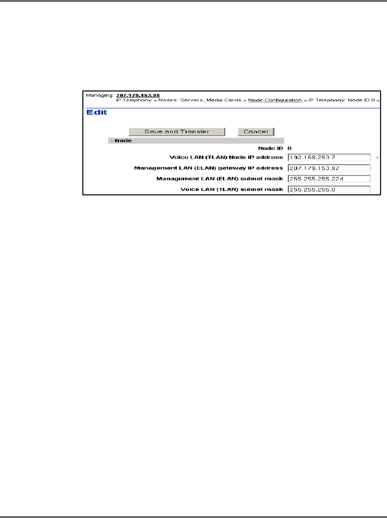
IP Line administration using Element Manager Page 607 of 910
IP Line Description, Installation and Maintenance
3Expand the Node section, if it is not already expanded, by clicking the
plus sign (+) to the left of the Node ID.
See Figure 199 on page 607.
Figure 199
Node properties
a. Node ID: The Node ID appears automatically.
b. Voice LAN (TLAN) Node IP address: Enter the Voice LAN (TLAN)
Node IP address in dotted decimal format. The Voice LAN Node IP
address is on the TLAN subnet. The Node IP address is the IP
address used by the IP Phones to communicate with the Voice
Gateway Media Cards on the TLAN subnet. If a Voice Gateway
Media Card becomes the primary card (Leader) during an election, it
assigns itself the Node IP address.
•If the node IP address is changed, this affects the configuration of
the Connect Server IP address in the DHCP Server for the IP
Phones.
• If the IP Phones are using partial DHCP mode, manually
reconfigure the IP address of each IP Phone.

Page 608 of 910 IP Line administration using Element Manager
553-3001-365 Standard 4.00 August 2005
c. Management LAN (ELAN) gateway IP address: Enter the
Management LAN (ELAN) gateway IP address in dotted decimal
format. This is the IP address of the gateway of the subnet to which
the Voice Gateway Media Card belongs. This is the IP address of the
router interface on the ELAN subnet, if present. If the subnet does not
have a Management LAN gateway, enter 0.0.0.0.
• When a Management LAN gateway is added to the ELAN subnet,
it must restrict access so that only authorized traffic is permitted
on the ELAN subnet.
• The router must disable the BootP relay agent for the ELAN
network interface.
• The router must block all broadcast and multicast traffic from the
ELAN subnet and enable only proper access (that is, only
authorized traffic and users coming through the ELAN gateway).
d. Management LAN (ELAN) subnet mask: Enter the Management
LAN subnet mask address in dotted decimal format. This is the
subnet mask that is used along with the ELAN network interface IP
address to identify to which subnet the Voice Gateway Media Card
belongs. When changing these subnet masks, consider the
possibility of conflict between the ELAN and TLAN network interface
IP addresses. Consult with the network administrator before making
any changes to subnets. Refer to “Codecs” on page 287.
When changing the Management LAN (ELAN) network interface IP
address, this must be coordinated with the IP address on the Call
Server (Active ELNK) network interface. Changes must also be
coordinated with the following:
• Management LAN gateway, and other IP devices on the ELAN
subnet
• any other devices on the ELAN subnet and customer’s enterprise
network subnet that need to communicate with IP Line 4.5
• devices that are looking to receive SNMP traps
e. Voice LAN (TLAN) subnet mask: Enter the Voice LAN subnet mask
address in dotted decimal format. This is the subnet mask that is
used, along with the TLAN network interface IP address, to identify
the subnet to which the Voice Gateway Media Card belongs.
Coordinate with the Voice LAN gateway (router). When changing the
Voice LAN (TLAN) subnet mask, the change must be coordinated
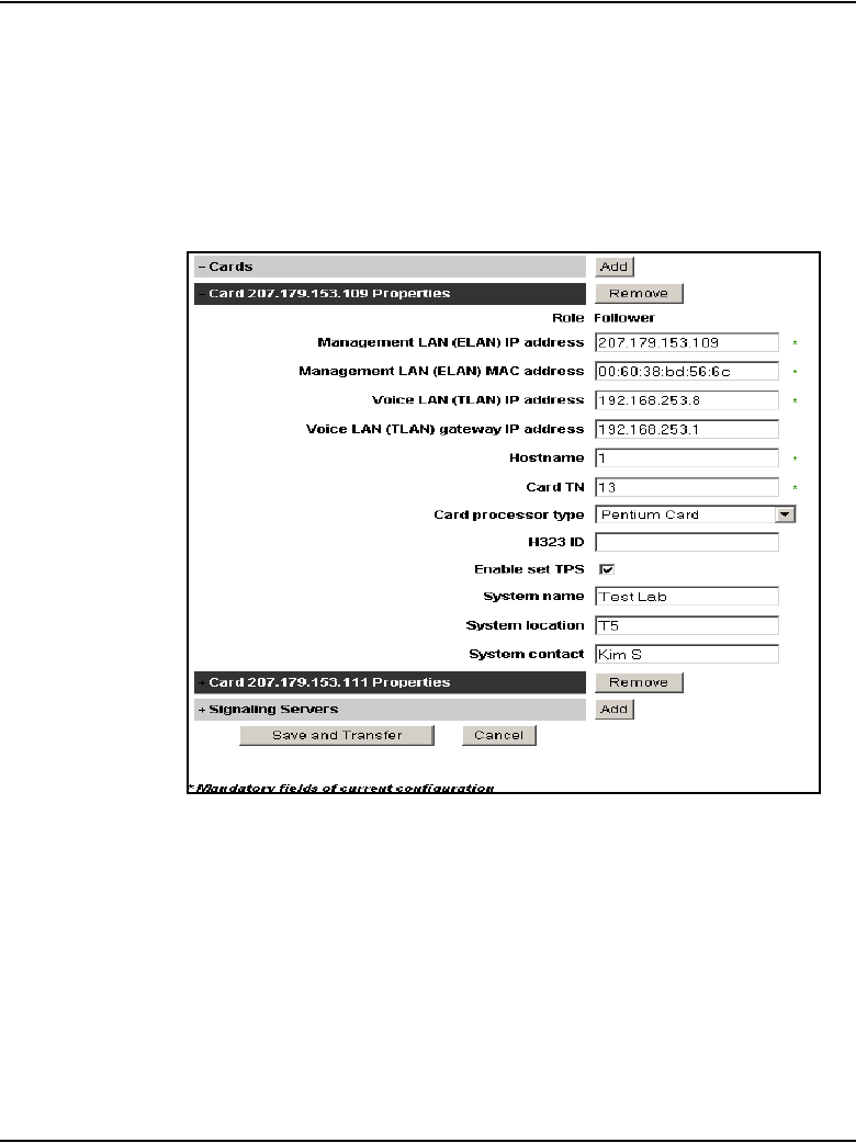
IP Line administration using Element Manager Page 609 of 910
IP Line Description, Installation and Maintenance
with a change to the subnet mask of the Voice LAN (TLAN) gateway
(router) network interface.
4Expand the Cards section and select the card to be changed.
See Figure 200 on page 609.
Figure 200
Cards
5Enter the Card Properties data for the Leader and Follower cards:
a. Role: There must be at least one card in the node. This card is the
Leader. Every IP Telephony node must have only one Leader. All
other cards function as Followers. This field is read-only.

Page 610 of 910 IP Line administration using Element Manager
553-3001-365 Standard 4.00 August 2005
b. Management LAN (ELAN) IP address: This is the ELAN network
interface IP address for the card. Element Manager and the system
use this address to communicate with the card.
If changing the Management LAN network interface IP address of the
Leader card, Telnet to the card and use the setLeader command to
make the same change (new Management IP address) in the
NVRAM of the Leader card.
The Leader card must be reset to resume communication with the
node.
Note: Before resetting the Leader card, unplug all the other cards to
prevent any other card from becoming the Master. When the Leader
restarts, plug the cards back in. These other cards receive their new
configuration from Leader 0.
c. Management LAN (ELAN) MAC address: This is the motherboard
Ethernet address from the “Voice Gateway Media Card installation
summary sheet” on page 307. All other IP address configuration
depends on the accurate configuration of the Management MAC
address. The MAC address is located on the faceplate of the Voice
Gateway Media Card and is labelled as MOTHERBOARD Ethernet
address. The Management MAC address corresponds to the ELAN
address.
d. Voice LAN (TLAN) IP address: This is the card Voice network
interface IP address. This address is also known as the card TLAN
network interface IP address. In an IP Telephony node, all cards
must be assigned an IP address on the same TLAN subnet. The card
Voice network interface IP address must be distinct from the node IP
address.
e. Voice LAN (TLAN) gateway IP address: This is the IP address of
the router interface on the TLAN subnet. All cards in the IP Telephony
node must be on the TLAN subnet; therefore, they all share the same
Voice LAN /TLAN gateway IP address.
6On the Node > Edit window, click SNMP.
See Figure 201 on page 611.
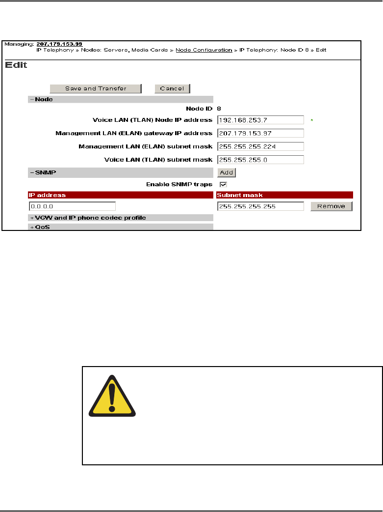
IP Line administration using Element Manager Page 611 of 910
IP Line Description, Installation and Maintenance
Figure 201
Node > Edit > SNMP
7Select the Enable SNMP traps check box, if configuring one or more
SNMP management IP addresses to receive SNMP traps from cards in
the IP Telephony node.
f. IP address: Enter the IP address of the trap destination. If SNMP
traps are enabled, the SNMP traps are sent to the IP address entered
here. More than one IP address can be configured.
g. Subnet mask: the subnet mask for the IP address of the trap
destination must always be configured as 255.255.255.255.
WARNING
Do not enter the actual value of the subnet mask on the
interface of the SNMP trap destination. Doing so can
cause misrouting of RTP media and signaling, leading to
no speech path between the IP Phones and the Voice
Gateway Media Cards or failure of the IP Phones to
register with the LTPS
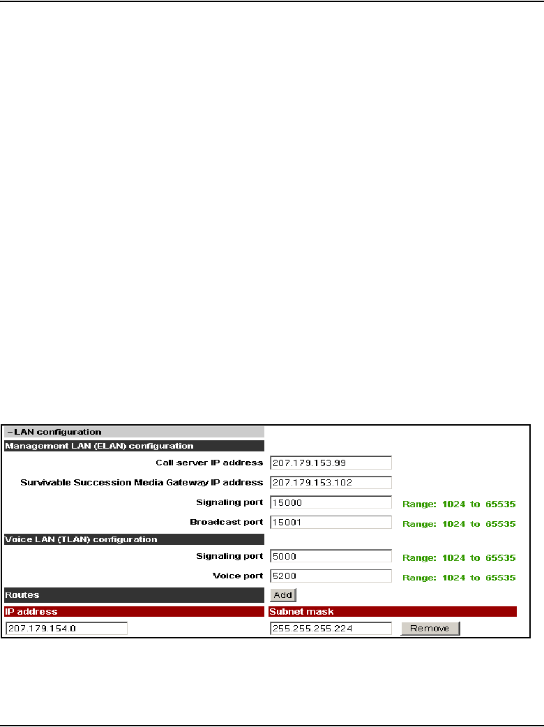
Page 612 of 910 IP Line administration using Element Manager
553-3001-365 Standard 4.00 August 2005
h. Click ADD to enter the IP address for another trap destination.
Add destination SNMP Manager IP addresses for the following:
• local or remote OTM server
• PPP IP address configured in the router on the ELAN subnet
for the remote-support OTM PC
• SNMP manager for remote alarm monitoring.
Note 1: Up to eight SNMP trap destinations can be defined.
Note 2: A net route or host route through the Management (ELAN)
gateway is added to the Voice Gateway Media Cards IP Routing Table for
each SNMP management address that is added to the SNMP traps list.
To remove an SNMP trap destination, click the corresponding Remove
button
Changes can be made to the SNMP trap destinations without affecting
other IP addresses. Change the SNMP trap destinations as required,
based on the trap destination to be reached.
8Expand the LAN Configuration section.
See Figure 202.
Figure 202
LAN configuration

IP Line administration using Element Manager Page 613 of 910
IP Line Description, Installation and Maintenance
9Enter the following Management LAN (ELAN) configuration settings:
a. Call Server IP address: This is the IP address of the Call Server on
the ELAN subnet. Enter the Call Server ELAN network interface IP
address (Active ELNK).
Note: The Call Server ELAN network interface IP address must
correspond to the Active ELNK IP address configured in LD 117. It must
be on the same subnet as the ELAN IP address for the IP Line node.
b. Survivable Media Gateway IP address: This is the IP address of
the Survivable Media Gateway on the ELAN subnet.
Note 1: The Survivable Media Gateway IP address must correspond to
the Active ELNK IP address. If configured, all Voice Gateway Media
Cards in the same node should be in the same Survivable Cabinet.
Note 2: The Survivable Media Gateway associated with the primary
Signaling Server IP Telephony node is called the Alternate Call Server. It
is usually located in the same equipment rack with the Call Server and
Signaling Server. Therefore it is usually connected to the same ELAN
subnet as the Call Server and the primary Signaling Server IP Telephony
node. The Alternate Call Server Media Gateway is equipped with
sufficient trunk cards and Voice Gateway Media Cards, and centralized
CallPilot. This provides a large degree of survivability in case of Call
Server equipment failure for IP Phone users who normally register
through the Signaling Server.
Refer to Communication Server 1000S: Installation and Configuration
(553-3031-210)) for more information about survivability on the
CS 1000S.
Refer to Communication Server 1000M and Meridian 1: Small System
Installation and Configuration (553-3011-210) and Communication
Server 1000M and Meridian 1: Large System Installation and
Configuration (553-3021-210) for more information about survivability on
the Meridian 1 and CS 1000M.
Refer to Communication Server 1000E: Installation and Configuration
(553-3041-210) for more information about survivability on the CS 1000E.
c. Signaling port: The default value is 15000. The range is 1024 to
65535.
d. Broadcast port: The default value is 15001. The range is 1024 to
65535.
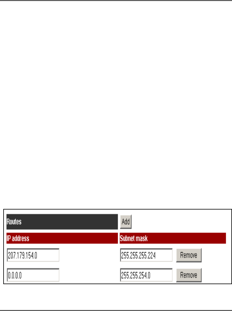
Page 614 of 910 IP Line administration using Element Manager
553-3001-365 Standard 4.00 August 2005
10 Under Voice LAN (TLAN) configuration:
a. Signaling port: The default value is 5000. The range is 1024 to
65535.
Note: The TLAN subnet Signaling occurs on UDP ports 7300, 4100,
5100, and 5000.
b. Voice port: Change the Voice port only as instructed by the IP
network administrator to improve Quality of Service for the
IP Phones. This field displays the range for RTP packets sent to the
IP Phones. For example, if RTP Header compression is used to
reduce voice bandwidth on narrow band WAN links, then the TLAN
voice port range needs to be set to 16384 or higher.
The exact range is provided by the system administrator. In general,
use the default value of 5200. If, however, numerous IP Phones are
working over low bandwidth WAN links using CISCO RTP header
compression, then change the voice port to a number in the range of
16384 to 32767. Coordinate this value change with the IP network
administrator.
Note: The TLAN Voice port range is 1024 to 65535. The default Voice
ports are 5200 – 5295. A check is performed to prevent the TLAN Voice
and signaling UDP ports from having the same range.
11 If entries must be made to the card routing table, click the Add button to
the right of Routes.
The Routes fields expand. See Figure 203.
Figure 203
Routes
IP Line administration using Element Manager Page 615 of 910
IP Line Description, Installation and Maintenance
12 Enter the IP address and Subnet mask for any host that is not on the
ELAN subnet but requires access to the Voice Gateway Media Card
across the ELAN subnet.
A Telnet session for maintenance from a remote PC is an example of
when this would be needed. The address of the remote PC would be
added in the Route list.
The default route on the card causes packets for unknown subnets to be
sent out the TLAN network interface. Packets from an external host arrive
on the ELAN network interface. Responses are sent on the TLAN network
interface. This process can cause one-way communication if the TLAN
subnet is not routed to the ELAN subnet. It is necessary to add an entry
in the Route list to correct the routing so that response packets are sent
on the ELAN subnet. Each entry creates a route entry in the card's route
table that directs packets out the ELAN network interface. See Figure 94
on page 391).
To add additional routes, click the Add button again and enter the route
information. Repeat this step for each route to be added.
13 Click Save and Transfer and then click OK.
14 In the Node Configuration window, click the Transfer/Status button
associated with the node that had the IP address changes.
End of Procedure
CAUTION
Use caution when assigning card routing table entries.
Do not include the IP address of an IP Phone.
Otherwise, voice traffic to these IP Phones is incorrectly
routed through the ELAN subnet and ELAN gateway. To
avoid including the wrong IP address, Nortel
recommends that Host IDs be defined for the card
routing table entries.

Page 616 of 910 IP Line administration using Element Manager
553-3001-365 Standard 4.00 August 2005
Restart a Voice Gateway Media Card
If the IP address of a single Voice Gateway Media Card has changed, it must
be restarted in order for the changes to take effect.
Note: If IP addresses that affect the entire node are changed, all cards in
the node must be restarted. See “Restart all the Voice Gateway Media
Cards” on page 619.
Changes to the SNMP trap destination IP addresses take place immediately
when the transfer occurs; restarting the cards is not required.
If the IP address of a Voice Gateway Media Card has changed, restart only
that card.
Follow the steps in Procedure 81 to restart a specific card using the CLI.
Alternatively, a Voice Gateway Media Card can be restarted from within
Element Manager. Follow the steps in Procedure 82 to restart the card using
Element Manager.
Procedure 81
Restarting a Voice Gateway Media Card at the CLI
1To prevent interruption to the speech path, log into LD 32.
2Type the DISI command.
This command disables the voice gateway channels when they become
idle. DISI removes the call traffic but does not remove the IP Phones that
are registered on that Voice Gateway Media Card. The Graceful TPS
Disable command disiTPS removes the registered IP Phones.
3Type disiTPS at the card’s IPL> prompt to disable the LTPS service on
the Voice Gateway Media Card.
This Graceful TPS Disable command prevents new IP Phones from
registering on the card. All IP Phones registered on the card are
re-directed to another Voice Gateway Media Card when the IP Phone
becomes idle.

IP Line administration using Element Manager Page 617 of 910
IP Line Description, Installation and Maintenance
After the command is entered, an idle IP Phone should be updated with
the Watchdog reset message. However, the LTPS sends a soft reset
message to the IP Phone, re-directing it to the Connect Server. The
disabled LTPS does not accept new registrations, so the IP Phones must
register with another LTPS in the node. Eventually, as all of the LTPS’s IP
Phones become idle, they are registered with other TPSs. The Voice
Gateway Media Card can then be removed with no impact to any users.
End of Procedure
Procedure 82
Restarting a Voice Gateway Media Card in Element Manager
1In the Element Manager navigator, click IP Telephony > Nodes:
Servers, Media Cards > Maintenance and Reports.
The Node Maintenance and Reports window opens.
2Expand the node containing the Voice Gateway Media Card by clicking
the plus sign (+) to the left of the Node ID.
3Click the Reset button associated with the Voice Gateway Media Card.
See Figure 204 on page 618.
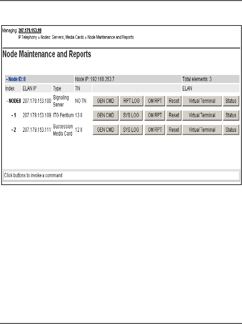

IP Line administration using Element Manager Page 619 of 910
IP Line Description, Installation and Maintenance
Figure 205
Card Reset dialog box
End of Procedure
Restart all the Voice Gateway Media Cards
All the Voice Gateway Media Cards must be restarted if there has been a
change to the following:
• node IP address
• subnet of either the TLAN or ELAN (by changing the subnet mask or the
subnet fields of the IP address)
These changes affect the whole node. As a result, all the cards must be
restarted.
If the Management (ELAN) network interface IP address of the Leader has
changed, all the cards must be restarted. Even though this is a change to a
single card, this change affects all cards, as this IP address is used to transmit
properties to the node.
Follow the steps in Procedure 83 to restart all the Voice Gateway Media
Cards.
Procedure 83
Restarting all Voice Gateway Media Cards
1Telnet to the card.
2Use the setLeader command to configure the new IP address.
The Leader uses this new IP address when it reboots.

Page 620 of 910 IP Line administration using Element Manager
553-3001-365 Standard 4.00 August 2005
3Reboot the Leader using the cardReset command.
The Leader card reads the new IP address from NVRAM.
4Restart all the other cards.
End of Procedure
Update other node properties
Some basic Voice Gateway Media Card configuration must be performed
from the IP Telephony Node Edit window.
To update the node properties in the following sections:
• DSP Profile section – follow the steps in Procedure 29 on page 380
• QoS section – follow the steps in Procedure 30 on page 385
Telnet to a Voice Gateway Media Card using
Virtual Terminal
To access the CLI on a Voice Gateway Media Card using Virtual Terminal
from Element Manager, follow the steps in Procedure 84.
Procedure 84
Accessing a Voice Gateway Media Card using Telnet
1In the Element Manager navigator, click IP Telephony > Nodes:
Servers, Media Cards > Maintenance and Reports.
The Node Maintenance and Reports window opens.
2Expand the node containing the Voice Gateway Media Card.
3Click the Virtual Terminal button associated with the Voice Gateway
Media Card.
See Figure 206 on page 621.
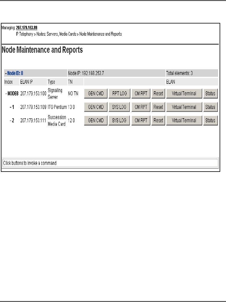
IP Line administration using Element Manager Page 621 of 910
IP Line Description, Installation and Maintenance
Figure 206
Virtual Terminal
The Virtual Terminal window opens and automatically connects to the
Voice Gateway Media Card by using the TLAN or ELAN network interface
IP address. See Figure 207 on page 622.
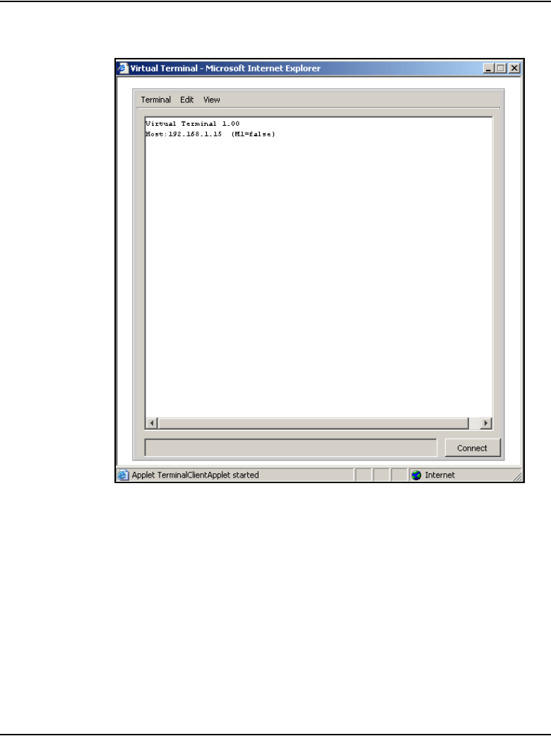
Page 622 of 910 IP Line administration using Element Manager
553-3001-365 Standard 4.00 August 2005
Figure 207
Virtual Terminal window
4Enter a user name and password to access the IPL> CLI.
Note: For Meridian 1 systems, the default user name and password are
both itgadmin. However, for security reasons, the user name and
password should have been changed during installation.
For CS 1000 systems, use the PWD1 user ID and password.
The IPL> prompt appears if the login is successful.
5Type ? at the prompt to display a list of available IPL> CLI commands.

IP Line administration using Element Manager Page 623 of 910
IP Line Description, Installation and Maintenance
See “IP Line CLI commands” on page 710 for a detailed list of commands.
End of Procedure
Check the Voice Gateway Channels
To check the Voice Gateway Channels running on a Voice Gateway Media
Card, follow the steps in Procedure 85.
Procedure 85
Checking the Voice Gateway Channels
1In the navigation tree, click IP Telephony > Nodes: Servers, Media
Cards > Maintenance and Reports.
The Node Maintenance and Reports window opens.
2Expand the node to show all its elements by clicking the plus sign (+) to
the left of the Node ID.
See Figure 208 on page 624.
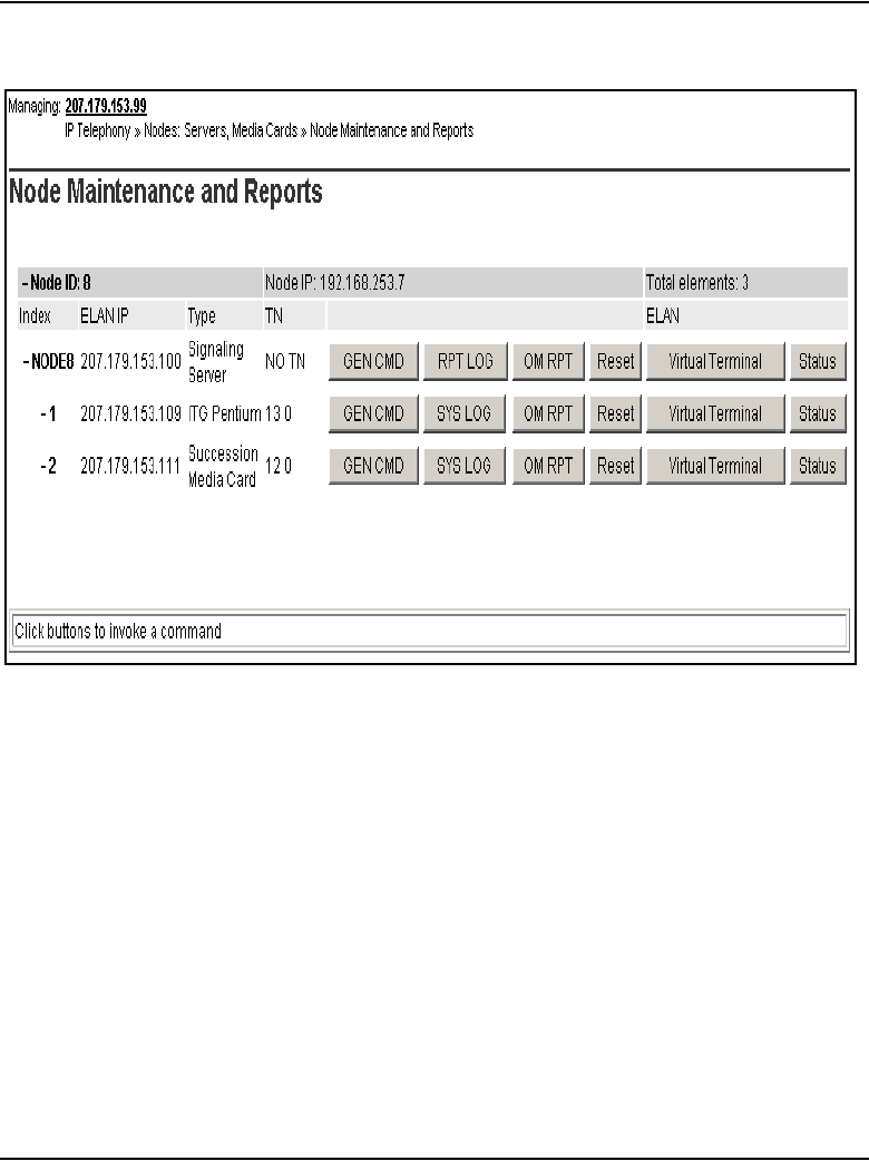
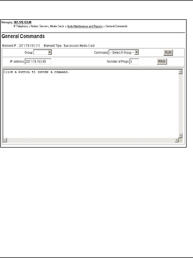
IP Line administration using Element Manager Page 625 of 910
IP Line Description, Installation and Maintenance
Figure 209
General Command
4From the Group drop-down list, select Vgw.
5From the Command drop-down list, select vgwShowAll.
6Click RUN.
The output of the vgwShowAll command is displayed in the text area at
the bottom of the window. See Figure 210 on page 626.
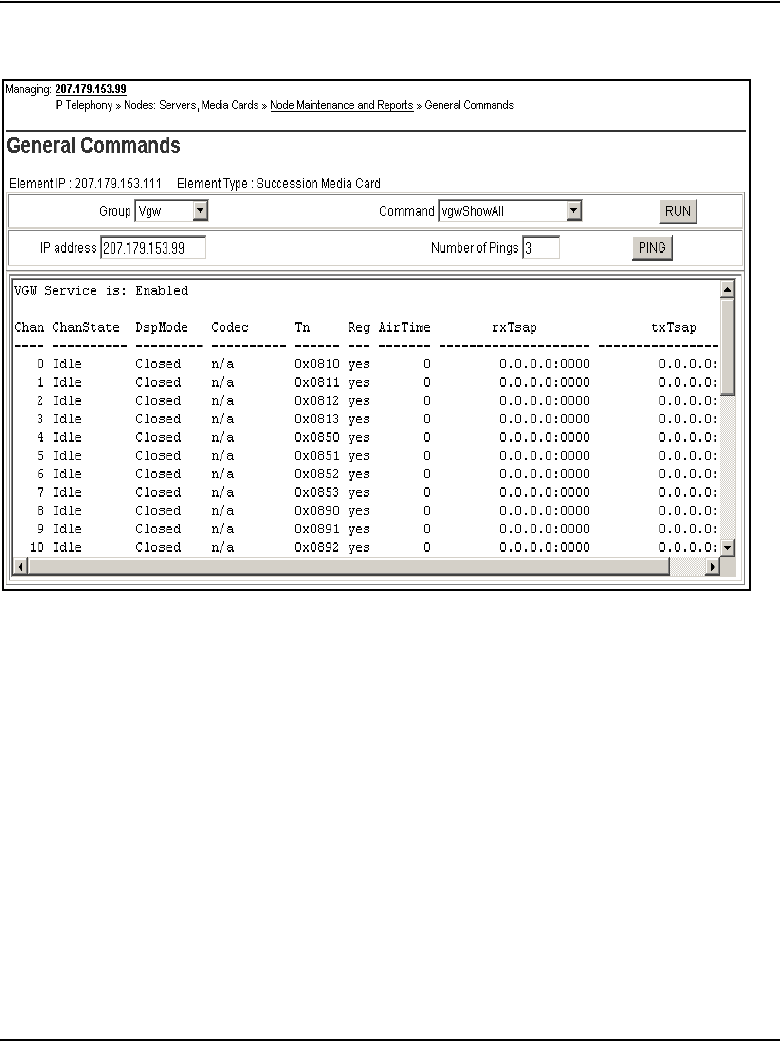
Page 626 of 910 IP Line administration using Element Manager
553-3001-365 Standard 4.00 August 2005
Figure 210
vgwShowAll output
7To view the VGW Channel configuration, from the Command drop-down
list, select Print VGW Channels and click the RUN button.
The output of the Print VGW Channels command is shown in Figure 211
on page 627.
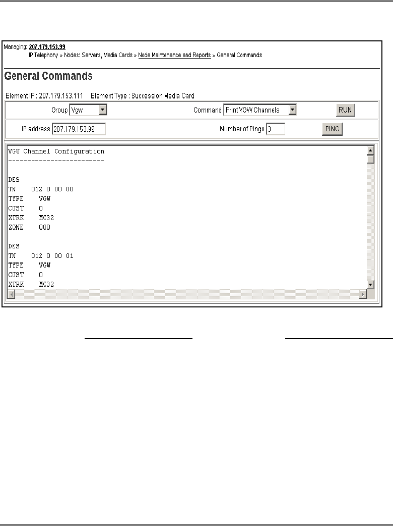
IP Line administration using Element Manager Page 627 of 910
IP Line Description, Installation and Maintenance
Figure 211
Output of Print VGW Channels
End of Procedure
Setting the IP Phone Installer Password
Element Manager includes the CLI commands for setting the administrative
and temporary IP Phone Installer Password. For detailed information about
the IP Phone Installer Password, refer to the section “IP Phone Installer
Password” on page 543.
To set the IP Phone Installer Password in Element Manager, follow the steps
in Procedure 86 on page 628.
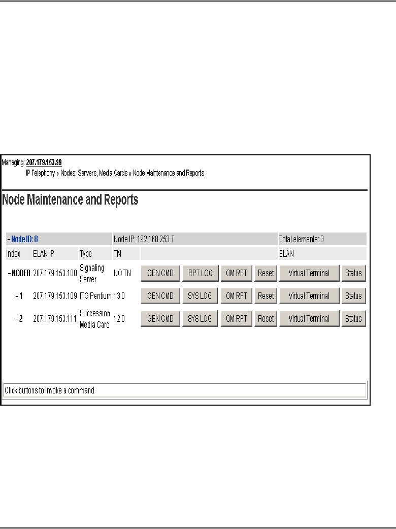
Page 628 of 910 IP Line administration using Element Manager
553-3001-365 Standard 4.00 August 2005
Procedure 86
Setting the administrative and temporary IP Phone Installer Passwords
1Click IP Telephony > Nodes: Servers, Media Cards > Maintenance
and Reports.
The Node Maintenance and Reports window opens.
2Expand the node to show all its elements.
See Figure 212.
Figure 212
IP Telephony Information window
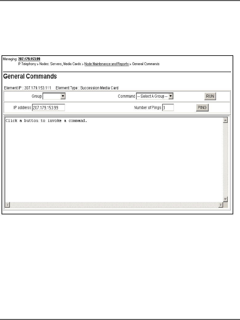
IP Line administration using Element Manager Page 629 of 910
IP Line Description, Installation and Maintenance
3Click the GEN CMD button associated with the Voice Gateway Media
Card.
The General Commands windows opens. See Figure 213.
Figure 213
General Command
4From the Group drop-down list, select nodePwd.
5From the Command drop-down list, select nodePwdShow and click the
RUN button.

Page 630 of 910 IP Line administration using Element Manager
553-3001-365 Standard 4.00 August 2005
The output of the nodePwdShow command is displayed in the text area
at the bottom of the window. If in the default state, the IP Phone Installer
Password has never been set. The nodePwdShow output should display
the following:
where:
NodeID – the IP Phone Installer Password configuration applies to all
Voice Gateway Media Cards on the same TLAN subnet that belong to this
Node ID.
PwdEna – by default the cards should be in disabled state (PwdEna=No).
The PwdEna setting specifies the enabled (Yes) or disabled (No) state of
the IP Phone Installer Password.
Pwd – this is the administrator IP Phone Installer Password. In the default
state, the administrator password is null.
TmpPwd – this is the temporary IP Phone Installer Password. In the
default state, the temporary password is null.
Uses – the Uses parameter applies to the temporary IP Phone Installer
Password. In the default state, this setting is null. If the card is not in the
default state, the Uses parameter is a numeric value from 0 – 1000. This
number specifies the remaining number of uses for the temporary
password. If zero is entered for the Uses parameter when setting the
temporary password, the Time parameter is mandatory. When the Time
parameter is in effect, the password expiration is based on time instead
of the number of uses.
Timeout – the Timeout heading corresponds to the Timeout parameter of
the temporary IP Phone Installer Password. In the default state the
Timeout is null. If the card is not in the default state, this setting specifies
the duration in hours in which the temporary password is valid. The range
is 0 – 240 hours (which is a maximum of 10 days). The number specified
under Timeout indicates the remaining time to expire of the temporary
password. The Timeout parameter is optional if the Uses parameter is
non-zero. The Timeout parameter is mandatory if Uses is set to zero.
NodeID
======
123
PwdEna
=======
No
Pwd
========
TmpPwd
========
Uses
=======
0
Timeout
===========
0d 0h 0m 0s
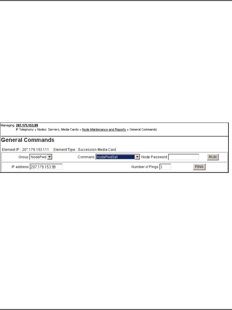
IP Line administration using Element Manager Page 631 of 910
IP Line Description, Installation and Maintenance
If both the Uses and Timeout parameters are entered, the password
expires based on whichever happens first, that is, the number of Uses is
reduced to zero or the Timeout has expired. If both the Uses and Timeout
parameters are entered and are set to zero, it is the same as not setting
the temporary password.
6From the Group drop-down list, select NodePwd.
7From the Command drop-down list, select nodePwdSet and click the
RUN button.
The window refreshes and displays the blank Node Password field. See
Figure 214.
8Enter the administrator IP Phone Installer Password in the Node
Password field and click the RUN button.
Figure 214
Node Password
This enables and configures the administrator password. The “password”
parameter can be null, or 6 to 14 digits in length. The valid characters are
0-9 * #. This command can be entered at any time. The new password
entered overwrites the previous password.
The text area returns the message 'Please run nodePwdShow to verify
the result.”
9From the Command drop-down list, select nodePwdShow and click
RUN.
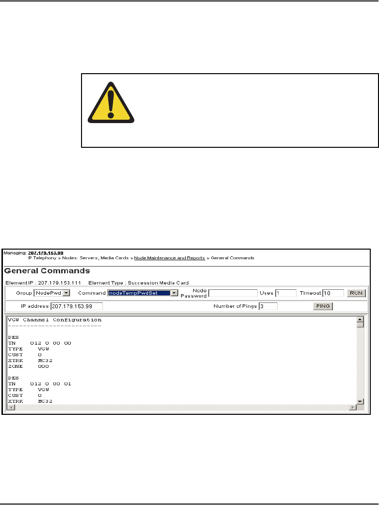
Page 632 of 910 IP Line administration using Element Manager
553-3001-365 Standard 4.00 August 2005
The text area data output is similar to the following:
10 To configure a temporary password, from the Command drop-down list,
select nodeTempPwdSet.
The window refreshes and blank fields are displayed for the following:
Node Password, Uses, and Timeout. See Figure 215.
Figure 215
Temporary password fields
11 Enter the temporary Node Password, the number of uses, and the
Timeout, and click RUN.
NodeID
======
123
PwdEna
=======
Ye s
Pwd
========
1234567
TmpPwd
========
Uses
=======
Timeout
===========
0d 0h 0m 0s
WARNING
If the RUN button in the Node Password field is clicked
and no password is entered in the text box, then the
password is enabled but is null. In the above output, the
PwdEna field displays “Yes” and the Pwd field is blank.

IP Line administration using Element Manager Page 633 of 910
IP Line Description, Installation and Maintenance
The text area returns the message 'Please run nodePwdShow to verify
the result.”
12 From the Command drop-down list, select nodePwdShow from the
drop-down list box and click RUN.
The text area data output is similar to the following:
13 To clear the temporary IP Phone Installer password, select the
nodeTempPwdClear command from the Command drop-down list and
click RUN.
14 Confirm that the temporary password has been cleared.
From the Command drop-down list, select nodePwdShow and click
RUN.
The text area data output is similar to the following:
End of Procedure
NodeID
======
123
PwdEna
=======
Ye s
Pwd
========
1234567
TmpPwd
========
9876543
Uses
=======
2
Timeout
===========
0d 2h 0m 0s
NodeID
======
123
PwdEna
=======
Ye s
Pwd
========
1234567
TmpPwd
========
Uses
=======
Timeout
===========
0d 0h 0m 0s

Page 634 of 910 IP Line administration using Element Manager
553-3001-365 Standard 4.00 August 2005

Page 635 of 910
IP Line Description, Installation and Maintenance
686
IP Line administration using OTM 2.2
Contents
This section contains information on the following topics:
Introduction . . . . . . . . . . . . . . . . . . . . . . . . . . . . . . . . . . . . . . . . . . . . . . 636
OTM administration procedures . . . . . . . . . . . . . . . . . . . . . . . . . . . . . . 636
Operational Measurement report scheduling and generation . . . . . . . . . . . . . . . 636
Viewing the IP Line log files . . . . . . . . . . . . . . . . . . . . . . . . . . . . . . 649
Back up and restore OTM data . . . . . . . . . . . . . . . . . . . . . . . . . . . . . . . 650
Update IP Telephony node properties using OTM . . . . . . . . . . . . . . . . 650
Add a Voice Gateway Media Card to the node . . . . . . . . . . . . . . . . 651
Delete a Voice Gateway Media Card from the node . . . . . . . . . . . . 658
Delete the Leader Voice Gateway Media Card from the node . . . . 660
Change the IP addresses of an IP Telephony node in OTM. . . . . . . 661
Update Voice Gateway Media Card card properties. . . . . . . . . . . . . . . 673
Retrieve command . . . . . . . . . . . . . . . . . . . . . . . . . . . . . . . . . . . . . . 679
Add an IP Telephony node in OTM by retrieving an existing node . . . 681
IP Line CLI access using Telnet or local RS-232 maintenance port . . 685
Telnet to a Voice Gateway Media Card . . . . . . . . . . . . . . . . . . . . . . 685
Page 636 of 910 IP Line administration using OTM 2.2
553-3001-365 Standard 4.00 August 2005
Introduction
This chapter explains how to administer IP Line 4.5 and the Voice Gateway
Media Card on the systems using OTM 2.2.
Optivity Telephony Manager (OTM) provides a graphical user interface to
the Voice Gateway Media Card. OTM can be used to Telnet to the card,
install and upgrade software, configure alarm event reporting, view and
update card property and configuration data, add new cards to a node,
schedule reports and other related tasks.
OTM administration procedures
This section describes the OTM administration procedures using the OTM
IP Line 4.5 application. All references to OTM in the following procedures
assume the latest OTM version.
Operational Measurement report scheduling and generation
Operational Measurement (OM) reports provide important statistical and
traffic information and feedback to the system administrator to better
engineer the system. The information stored in the OM file applies only to the
calls routed over the IP network by way of IP Line 4.5. OM reports give a
quantitative view of system performance, such as jitter.
OTM is used to support Operational Measurements on the systems.
The OM reports are a collection of data from all the Voice Gateway Media
Cards in the network. OM data is written to a file every hour. At midnight, the
OM file is copied to a backup file, and the new day starts with a new file.
WARNING
The only support provided for nodes that reside on a
CS 1000 system is the retrieval of OM reports. Refer to
Procedure 87 on page 638 through Procedure 91 on
page 649.

IP Line administration using OTM 2.2 Page 637 of 910
IP Line Description, Installation and Maintenance
OTM uses the following naming convention for the IP Line 4.5 OM file
names:
ipline31_MM_YYYY_file1.csv
Note: The MM (month) portion of the filename is only one character for
the months of January to September (1-9). The remaining three months
appear as two digit numbers (10, 11, and 12).
An example is ipline40_10_2002_file1.csv. This comma-delimited file
opens in a program that interprets the .csv file, such as Microsoft Excel or any
other comma-delimited file reader.
OM reports are generated on demand or on a pre-selected schedule. When a
report is generated, the application retrieves the latest OM data from each
Voice Gateway Media Card defined in OTM.
Under certain conditions, the OM report is not available, as follows:
• the first hour after a Voice Gateway Media Card reboot
• the first hour after installing a new Voice Gateway Media Card
The following error messages are generated when requesting the OM report
during the first hour:
• on OTM: “fails to transfer the OM file”
• on the Voice Gateway Media Card console: “tfxl: Error File
C:/OM/omreport.xxx not found”
Note: Nortel recommends that report generation be scheduled once a
day.
To schedule a generated OM Report, follow the steps in Procedure 87 on
page 638.
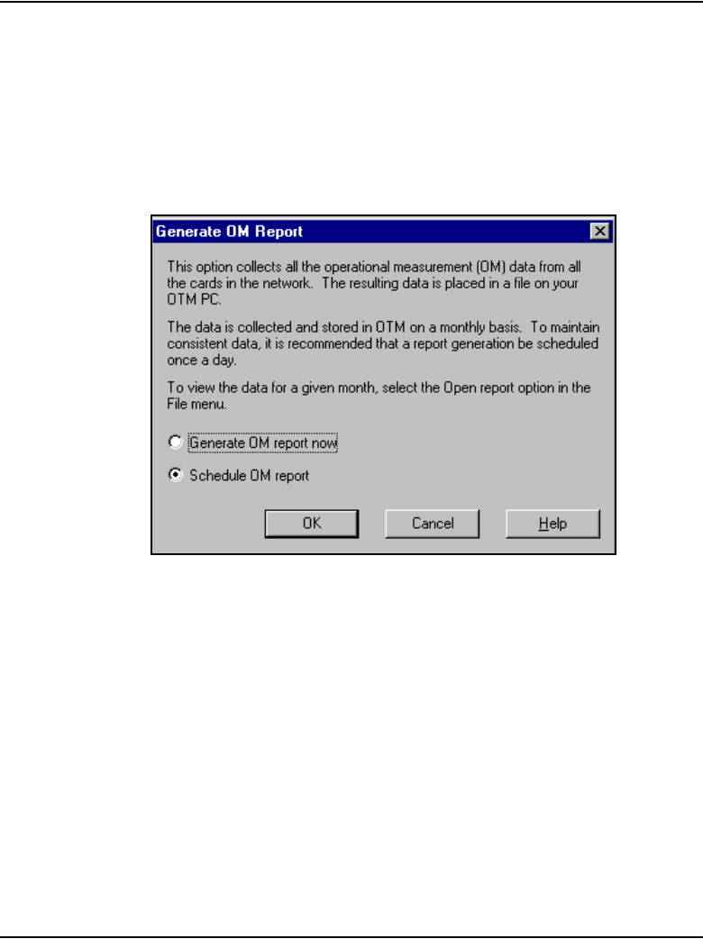
Page 638 of 910 IP Line administration using OTM 2.2
553-3001-365 Standard 4.00 August 2005
Procedure 87
Scheduling Reports
1Select the node in the IP Telephony window. Click File > Report >
Generate.
The Generate OM Report window opens. See Figure 216.
Figure 216
Generate OM Report – Schedule an OM report
In the Generate OM Report window there are two choices, Generate OM
report now and Schedule OM report.
2Select the Schedule OM report radio button. Click OK.
The Scheduling window opens. See Figure 217 on page 639.
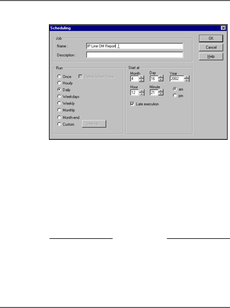
IP Line administration using OTM 2.2 Page 639 of 910
IP Line Description, Installation and Maintenance
Figure 217
Scheduling an OM Report
3Under Job, enter the Name and a Description for the scheduled OM
Report.
4Under Run, select the radio button that indicates the frequency of report
generation.
5Under Start at, enter the date and time of the start of the report period
using the Month, Day, Year, Hour, and Minute list boxes and the am or
pm radio buttons.
6Under Start at, click the Late execution check box if the report is to run
at a later time if the system is busy at the scheduled time.
7Click OK.
End of Procedure
Page 640 of 910 IP Line administration using OTM 2.2
553-3001-365 Standard 4.00 August 2005
The generated OM report includes information for all cards in all the nodes
in the system. The report file accumulates data for the month. The data is
stored in the generated file called ipline_MM_YYYY_file#.csv.
OTM has a report feature called “Generate OM Report now”. This feature
enables an OM Report to be generated immediately.
To generate an OM Report immediately, follow the steps in Procedure 88.
Procedure 88
Generating reports
1In the IP Telephony window, click the node. Click File > Report.
The Generate OM Report window opens. See Figure 218 on page 641.
WARNING
Running the “Generate OM Report now” feature while
the Scheduled OM Reports feature is also running
causes duplicate data to be displayed at the end of the
OM Report. The data for the current day is appended to
the end of the OM file by the “Generate OM Report Now”
option.
Be careful to take into account any duplicate data when
viewing system performance.
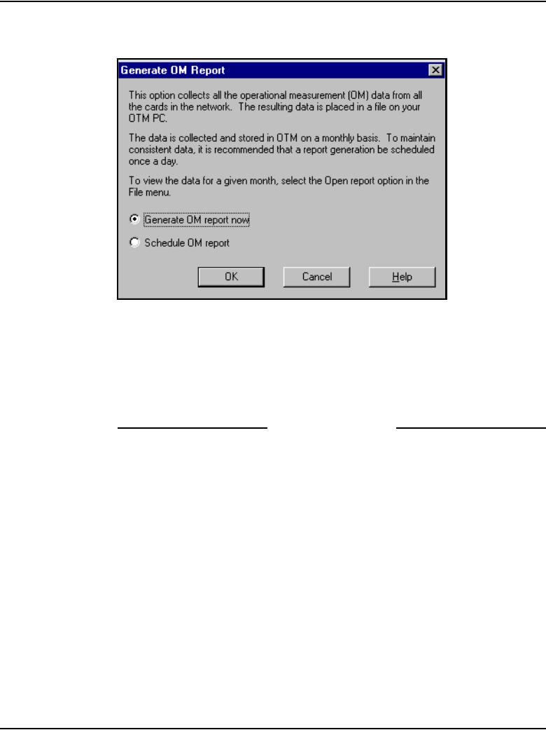
IP Line administration using OTM 2.2 Page 641 of 910
IP Line Description, Installation and Maintenance
Figure 218
Generate OM Report – Generate OM report now
2Click Generate OM report now and then click OK.
OTM creates and displays a report named Operational Measurement
Report. This report is saved as a comma-delimited file (csv):
ipline31_MM_YYYY_file#.csv. The default file that is generated opens in
Microsoft Excel or any other application that can open .csv files.
End of Procedure
To open and view the OM Report file, follow the steps in Procedure 89.
Procedure 89
Opening an Operational Measurement (OM) report
1In the IP Telephony window, select the node in the top of the window.
2Click File > Report > Open.
The Open OM Report window opens. See Figure 219 on page 642.
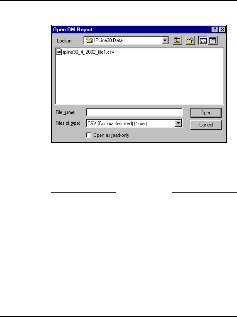
Page 642 of 910 IP Line administration using OTM 2.2
553-3001-365 Standard 4.00 August 2005
Figure 219
Open OM Report
3Select a report file and click Open.
The file opens in a program that interprets .csv (comma-delimited) files
such as Microsoft Excel. If Microsoft Excel is not installed on the PC, then
OTM notifies the user that the file will be opened in Wordpad.
End of Procedure
Operational Measurements (OM) information for a Voice Gateway Media
Card in the node can be viewed using OTM. This OM file is a view of the
LTPS and Voice Gateway channel activity for each model of IP Phone on that
card. (The OTM OM Report Generation feature is an overview of all the cards
in all sites and systems.)
The Voice Gateway Media Card OM file contains the following information
for each model of IP Phone:
• the number of incoming and outgoing calls
• the number of call attempts

IP Line administration using OTM 2.2 Page 643 of 910
IP Line Description, Installation and Maintenance
• the number of calls completed
• the total holding time for voice calls
To view a Voice Gateway Media Card’s OM file from OTM, follow the steps
in Procedure 90.
Procedure 90
Retrieving the current OM file from the Voice Gateway Media Card using
OTM
1In the OTM Navigator window, click the Services folder. Double-click the
IP Telephony icon.
The IP Telephony window opens.
2Select the node in the upper portion of the window.
3Select the Voice Gateway Media Card from the lower portion of the
window.
4Right-click the card and then select Properties from the pop-up menu.
The Card Properties window opens to the Maintenance tab. See
Figure 220 on page 644.
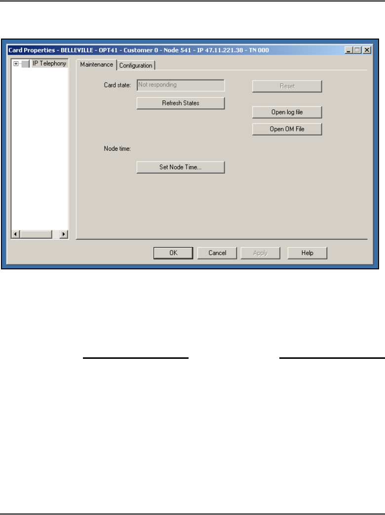
Page 644 of 910 IP Line administration using OTM 2.2
553-3001-365 Standard 4.00 August 2005
Figure 220
Card Properties – Maintenance tab
5Click the Open OM File button.
A file called om.txt opens in the WordPad application. The file contains
collection period information for each hour of the day that the card was
running, broken down for each model of IP Phone.
End of Procedure
The file contains collection period information for each hour of the day that
the card was running.
The collection periods start with the hour from midnight to 1:00 am. As each
hour passes, OTM adds another collection period to the OM file; therefore,
there is a maximum of 24 collection periods each day.

IP Line administration using OTM 2.2 Page 645 of 910
IP Line Description, Installation and Maintenance
Output
The OM report output tracks the statistics for each IP Phone type.
Data is first output for the Nortel versions of the IP Phone 2001,
IP Phone 2002, and IP Phone 2004, and IP Softphone 2050.
Note: The i2050 set type refers to both the IP Softphone 2050 and the
MVC 2050.
The IP Phone 2007 is output as type i2004. The IP Audio Conference
Phone is output as type i2001.
That output is followed by data for the 3rd-party IP Phones, labelled:
• 3Pi2001
• 3Pi2002
• 3Pi2004
• 3Pi2050
Finally, the data for the gateway channels is output.

Page 646 of 910 IP Line administration using OTM 2.2
553-3001-365 Standard 4.00 August 2005
Output example
An example of a single hour’s OM report is as follows:
collection_time : 9/5/2003 1:00
i2004Reg_Att: 0
i2004Reg_Fail: 0
i2004Unreg_Att: 0
i2004Aud_Setup: 0
i2004Jitter_Avg: 0.0
i2004Jitter_Max: 0
i2004Pkt_Lost: 0.00
i2004Voice_Time: 0 mins 0 secs
i2002Reg_Att: 0
i2002Reg_Fail: 0
i2002Unreg_Att: 0
i2002Aud_Setup: 0
i2002Jitter_Avg: 0.0
i2002Jitter_Max: 0
i2002Pkt_Lost: 0.00
i2002Voice_Time: 0 mins 0 secs
i2001Reg_Att: 0
i2001Reg_Fail: 0
i2001Unreg_Att: 0
i2001Aud_Setup: 0
i2001Jitter_Avg: 0.0
i2001Jitter_Max: 0
i2001Pkt_Lost: 0.00
i2001Voice_Time: 0 mins 0 secs
i2050Reg_Att: 0

IP Line administration using OTM 2.2 Page 647 of 910
IP Line Description, Installation and Maintenance
i2050Reg_Fail: 0
i2050Unreg_Att: 0
i2050Aud_Setup: 0
i2050Jitter_Avg: 0.0
i2050Jitter_Max: 0
i2050Pkt_Lost: 0.00
i2050Voice_Time: 0 mins 0 secs
3Pi2004Reg_Att: 0
3Pi2004Reg_Fail: 0
3Pi2004Unreg_Att: 0
3Pi2004Aud_Setup: 0
3Pi2004Jitter_Avg: 0.0
3Pi2004Jitter_Max: 0
3Pi2004Pkt_Lost: 0.00
3Pi2004Voice_Time: 0 mins 0 secs
3Pi2002Reg_Att: 0
3Pi2002Reg_Fail: 0
3Pi2002Unreg_Att: 0
3Pi2002Aud_Setup: 0
3Pi2002Jitter_Avg: 0.0
3Pi2002Jitter_Max: 0
3Pi2002Pkt_Lost: 0.00
3Pi2002Voice_Time: 0 mins 0 secs
3Pi2001Reg_Att: 0
3Pi2001Reg_Fail: 0
3Pi2001Unreg_Att: 0
3Pi2001Aud_Setup: 0
3Pi2001Jitter_Avg: 0.0

Page 648 of 910 IP Line administration using OTM 2.2
553-3001-365 Standard 4.00 August 2005
3Pi2001Jitter_Max: 0
3Pi2001Pkt_Lost: 0.00
3Pi2001Voice_Time: 0 mins 0 secs
3Pi2050Reg_Att: 0
3Pi2050Reg_Fail: 0
3Pi2050Unreg_Att: 0
3Pi2050Aud_Setup: 0
3Pi2050Jitter_Avg: 0.0
3Pi2050Jitter_Max: 0
3Pi2050Pkt_Lost: 0.00
3Pi2050Voice_Time: 0 mins 0 secs
ChanAud_Setup: 0
ChanJitter_Avg: 0.0
ChanJitter_Max: 0
ChanPkt_Lost: 0.00
ChanVoice_Time: 0 mins 0 secs
Each collection period provides the following information:
• The date and time for the collection period hour.
• LTPS information for IP Phones that are registered to the LTPS on the
Voice Gateway Media Card during that hour. The LTPS information is
prefixed by the model number (i2001, i2002, i2004, i2050). During
normal operation, the LTPS values for the Voice Gateway Media Card
can be zeros as the IP Phones normally register to the LTPS on the
Signaling Server.
• Voice Gateway channel information accumulated during the hour. The
Voice Gateway data is prefixed by Chan.
• Notes indicating whether the machine has been rebooted during the hour.

IP Line administration using OTM 2.2 Page 649 of 910
IP Line Description, Installation and Maintenance
The OM file relates to the omreport.xxx file on the Voice Gateway Media
Card, where xxx indicates the numbers of days since December 31.
In general, no relationship exists between the IP Phones registered on a card
and the Voice Gateway channels on the card (if two or more cards are used)
in the node. If only one card is used (with multiple IP Phones), a partial
correlation might exist between the IP Phones and the card information.
However, even with only one card, there still is not a 100% correlation, as an
IP Phone can still call another IP Phone without involving the Voice Gateway
channels.
Viewing the IP Line log files
OTM uses FTP to transfer the log file from the Voice Gateway Media Card
to the PC. The file is opened in WordPad. The IP Line Error log file (syslog)
displays error information, including error date/time, the originating module
(IP Telephony node), and specific error data.
To view IP Line error conditions that are abnormal events, but not severe
enough to raise an alarm, follow the steps in Procedure 91.
Procedure 91
Viewing IP Line info and error log
1In the OTM Navigator window, click the Services folder.
2Double-click the IP Telephony icon.
The IP Telephony window opens.
3Right-click the card and then select Properties from the pop-up menu.
The Card Properties window opens to the Maintenance tab. See
Figure 220 on page 644.
4Click the Open log file button and review the file contents.
End of Procedure
Page 650 of 910 IP Line administration using OTM 2.2
553-3001-365 Standard 4.00 August 2005
Back up and restore OTM data
The OTM Backup Wizard is used to backup and restore any or all OTM
PC-based data, including IP Line OTM data. All IP Line data is stored in an
Access database file on the OTM PC or Server. This file is backed up only
when the “Full OTM Backup” option is selected. This option backs up all
OTM data contained in the PC directory where OTM is installed and can only
be used to restore all data.
For more information on using the OTM Backup Wizard, see the Common
Services section in Optivity Telephony Manager: System Administration
(553-3001-330).
Update IP Telephony node properties using OTM
To update the node properties of a Voice Gateway Media Card, follow the
steps in Procedure 92.
Procedure 92
Updating the IP Telephony node properties
1In the OTM Navigator window, click the Services folder. Double-click the
IP Telephony icon. The IP Telephony window opens.
2Double-click on the node in the upper part of the window. The Node
Properties window appears.
Perform all required updates to the General tab and Configuration tab
parameters. The General and Configuration tabs are used to set the node
properties. The other tabs affect the CONFIG.INI file and are also known
as the card-affecting properties tabs. If any node or card property is
changed, the configuration data must be transmitted to the node or the
card.
CAUTION
This procedure is not supported for a node that resides
on a CS 1000 system.

IP Line administration using OTM 2.2 Page 651 of 910
IP Line Description, Installation and Maintenance
3If Voice Gateway Media Cards are added, deleted or replaced in the node
or if a Voice Gateway Media Card is replaced, then use one of the
following procedures:
• “Add a Voice Gateway Media Card to the node” on page 651
• “Delete a Voice Gateway Media Card from the node” on page 658
• “Delete the Leader Voice Gateway Media Card from the node” on
page 660
• “Change the IP addresses of an IP Telephony node in OTM” on
page 661
• “Replacing a Leader Voice Gateway Media Card” on page 801
End of Procedure
Add a Voice Gateway Media Card to the node
To add a Voice Gateway Media Card to the node, follow the steps in
Procedure 93.
Procedure 93
Adding a Voice Gateway Media Card to the node
1Choose a card slot for the new card. Note the TN.
2Configure IPTN on the system in LD 14 at the Call Server.
3Install the I/O cables for connection to the ELAN and TLAN subnets on
the selected card slot.
4In the OTM Navigator window, click the Services folder.
5Double-click the IP Telephony icon.
The IP Telephony window opens.
6Double-click the node in the upper portion of the window.
The Node Properties window opens.
CAUTION
This procedure is not supported for a node that resides
on a CS 1000 system.
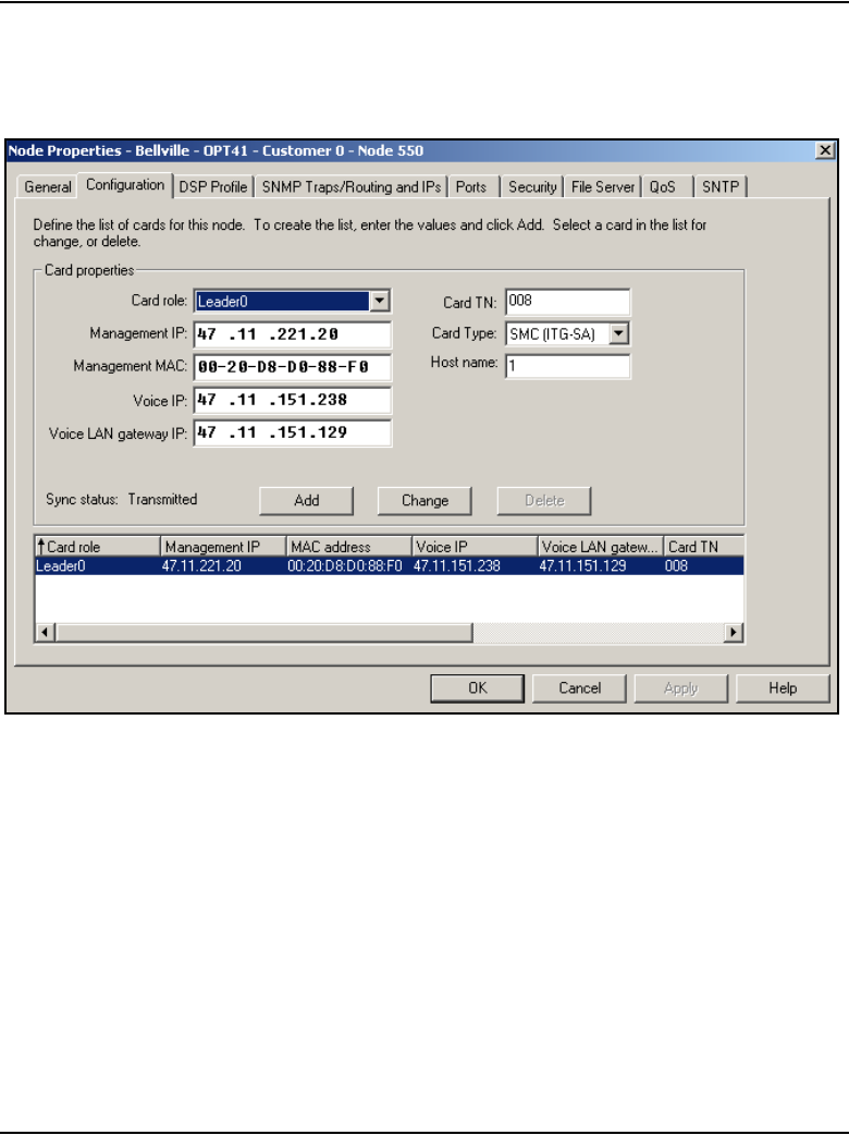
Page 652 of 910 IP Line administration using OTM 2.2
553-3001-365 Standard 4.00 August 2005
7Click the Configuration tab. See Figure 221 on page 652.
Figure 221
Node Properties – Configuration tab
8Enter the Card Properties data for Leader 1 and the Follower cards:
a. Card role: Assign the Card role Leader 0 to the first card configured.
Assign the second card configured as Leader 1. All remaining cards
are assigned as Followers.
b. Management IP: This is the ELAN network interface IP address for
the card. OTM and the system use this address to communicate with
the card.
c. Management MAC: This is the motherboard Ethernet address from
the “Voice Gateway Media Card installation summary sheet” on
page 306.

IP Line administration using OTM 2.2 Page 653 of 910
IP Line Description, Installation and Maintenance
d. Voice IP: This is the TLAN network interface IP address for the card.
e. Voice LAN gateway IP: This is the IP address of the router interface
on the TLAN subnet.
f. Card TN: For Large Systems, enter Card TN (l s c) information. For
Small Systems, enter only the card number between 0 – 50. The card
TN format is determined by the system type that is configured in the
OTM Navigator. Enter the correct system type in the OTM Navigator
before adding the node.
g. Card Type: Select Pentium for the ITG-P 24-port line card or
Strong Arm for the Media Cards.
9Click Add.
The card role and address information appear in a working list at the
bottom of the New Node window.
10 Click Apply to add the Card Properties to the Node.
11 If more cards are to be added, add them by repeating the previous steps.
Click OK when all the cards are added.
Prematurely clicking OK at this point, closes the window and saves any
changes. Double-click the new node in the upper part of the main
IP Telephony window to re-open Node Properties and complete the
configuration procedures.
12 In the OTM Navigator window, click the Services folder.
13 Double-click the IP Telephony icon.
The IP Telephony window opens.
14 From the list of IP Telephony nodes in the upper part of the window, select
the IP Telephony node to which configuration data will be transmitted.
15 Click Configuration > Synchronize > Transmit.
The Transmit Options window opens. Keep the default setting of
Transmit to selected nodes radio button. Select only the Node
Properties to Active Leader check box. See Figure 222 on page 655.
16 Click the Start transmit button.
17 Monitor progress under the Transmit Control window. Confirm that the
node properties are transmitted successfully to Leader 0.
18 When the transmission is complete, click the Close button.

Page 654 of 910 IP Line administration using OTM 2.2
553-3001-365 Standard 4.00 August 2005
19 Choose a card slot for the new card. Note the TN. Configure IPTN in
Meridian 1. See Table 65 on page 342.
20 Install the I/O cables for the connection to the ELAN and TLAN subnets
on the selected card slot.
Ensure that the I/O cables are connected to the ELAN and TLAN subnets.
21 In the OTM Navigator window, click the Services folder. Double-click the
ITG Line 4.5 icon.
The IP Telephony Gateway - IP Line 4.5 window opens.
22 From this list of IP Telephony nodes in the upper part of the window,
select the IP Telephony node to which the configuration data will be
transmitted.
23 Click the Configuration > Synchronize > Transmit.
The Transmit Options window opens.
24 Keep the default setting of Transmit to selected nodes radio button.
Check only the Node Properties to Active Leader check box.
See Figure 222 on page 655.
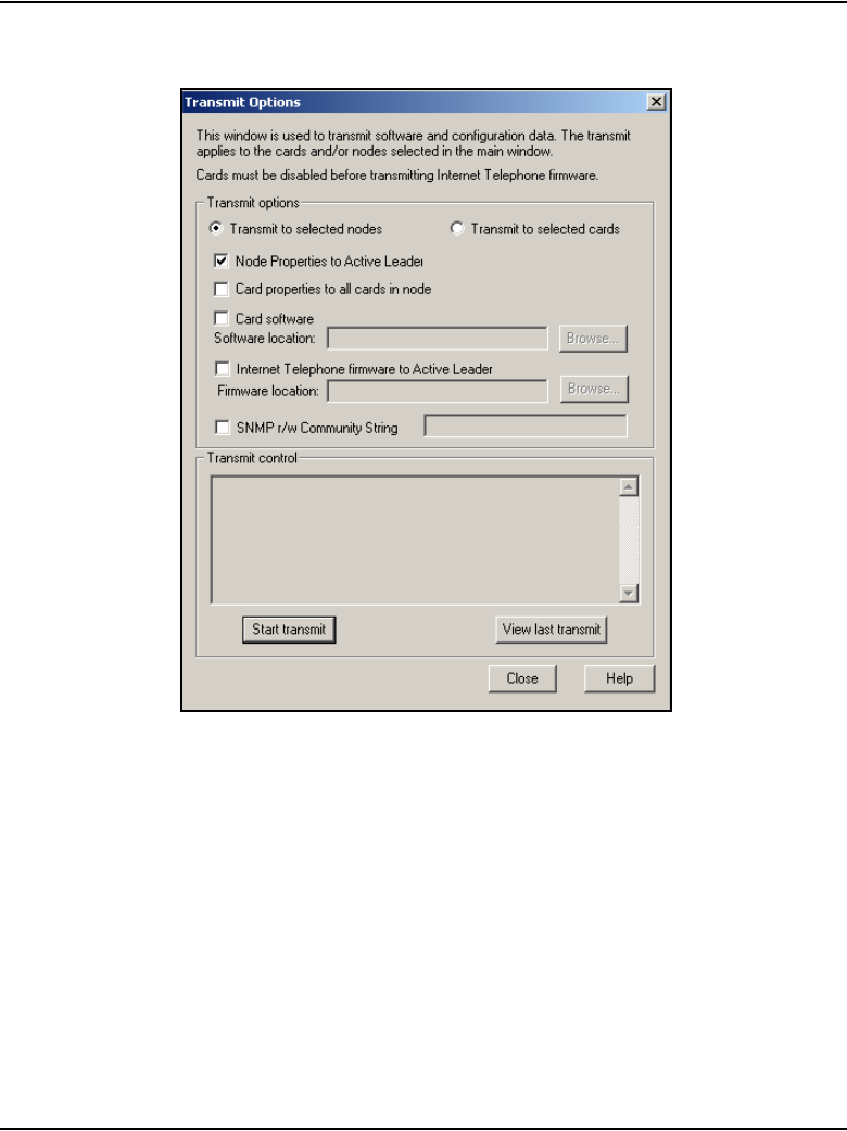
IP Line administration using OTM 2.2 Page 655 of 910
IP Line Description, Installation and Maintenance
Figure 222
Transmit Options
25 Click the Start transmit button.
Monitor the progress in the Transmit Control window. Confirm that the
node properties are transmitted successfully to Leader 0.
26 When the transmission is complete, click the Close button.
27 Insert the new card.
The card starts and obtains its IP configuration from the node master. This
process takes several minutes.

Page 656 of 910 IP Line administration using OTM 2.2
553-3001-365 Standard 4.00 August 2005
The Maintenance faceplate display shows an alarm of T:21 or S009.
• T:21 is displayed if the card is new and there is no CONFIG.INI file.
• S009 is displayed if the card has been used before and has a
CONFIG.INI file that contains an IP address for the Call Server that
is no longer correct.
28 In the OTM IP Line 4.5 application, refresh the view of the card status in
the node.
29 Verify the card is responding to OTM by selecting the IP Telephony node
from the list in the upper part of the main window.
All Voice Gateway Media Cards in the node are displayed in the lower part
of the window. While the node is selected, from the node list, press
function key F5 or View > Refresh > Selection to refresh the card status
of all cards in the selected node.
The card status should display as “Enabled” or “Disabled”. If the status is
“Not responding”, verify the network connection and the proper
configuration of the network equipment.
30 In the OTM Navigator window, click the Services folder.
31 Double-click the IP Telephony icon.
The IP Telephony window opens.
32 Select the IP Telephony node in the upper part of the window.
33 Select the new card(s) in the lower part of the window.
Hold down the Ctrl key to select multiple cards.
34 Click the Configuration menu option and then select Synchronize >
Transmit.
The Transmit Options window appears.
35 Click the Transmit to selected cards radio button.
See Figure 223 on page 657.
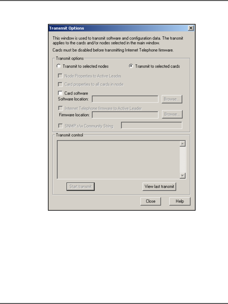
IP Line administration using OTM 2.2 Page 657 of 910
IP Line Description, Installation and Maintenance
Figure 223
Transmit Options – Transmit to selected cards
36 Click the Start transmit button.
Monitor the progress in the Transmit Control window.
37 When the transmission is complete, click the Close button.
38 Verify that all the new Voice Gateway Media Cards in the node have a
signaling link to the Call Server.
39 Telnet to each Voice Gateway Media Card and log in.
40 At the IPL> command line, enter the pbxLinkShow command.
Page 658 of 910 IP Line administration using OTM 2.2
553-3001-365 Standard 4.00 August 2005
Alternatively, observe the display on the card and ensure it is displaying
F000.
41 At this point, verify the card software and firmware version. Upgrade the
software and the firmware, if necessary, using Procedure 64 on
page 507, Procedure 65 on page 512, and Procedure 67 on page 517.
However, apply these procedures only to this card.
End of Procedure
Delete a Voice Gateway Media Card from the node
To delete a Voice Gateway Media Card from the node, follow the steps in
Procedure 94.
To delete the Leader 0 Voice Gateway Media Card from the node, follow the
steps in Procedure 95 on page 660.
Procedure 94
Deleting a Voice Gateway Media Card from the node
1In the OTM Navigator window, click the Services folder. Double-click the
IP Telephony icon.
The IP Telephony window opens.
2Select the node in the upper portion of the window.
3In the IP Telephony window, select Node > Properties from the popup
menu.
The Node Properties window opens.
4Click the Configuration tab.
5Select the Voice Gateway Media Card to be deleted from the working list
at the bottom of the window.
6Click the Delete button.
CAUTION
These procedures are not supported for a node that
resides on a CS 1000 system.
IP Line administration using OTM 2.2 Page 659 of 910
IP Line Description, Installation and Maintenance
7Click OK.
Next, transmit the node properties.
8In the IP Telephony window, click the Configuration > Synchronize >
Transmit.
The Transmit Options window opens.
9Select the Transmit to selected nodes radio button.
10 Select the Node Properties to Active Leader check box.
11 Click the Start transmit button.
Monitor progress in the Transmit Control window. Confirm that the node
properties are transmitted successfully to Leader 0.
12 When the transmission is complete, click the Close button.
13 Remove the Voice Gateway Media Card.
14 Remove the Voice Gateway Media Card configuration data from the Call
Server.
a. Identify the TN of the Voice Gateway Media Card.
b. In LD 20, enter the LTN (List Terminal Number) command where
TYPE = VGW to list the TNs on the Voice Gateway Media Card TN.
This returns a list of units equipped on the card. Verify the number of
units that are equipped on the card. Take note of the first unit
equipped on the card.
c. In LD 14, use the Out n command, where n equals the number of
units that are equipped on the card.
15 At the TN prompt, enter the TN for the first unit that was equipped on the
card, as determined in Step 15 in Procedure 93 on page 651. As the units
are deleted, verify that the intended units are “outed”.
End of Procedure
CAUTION WITH ESDS DEVICES
Follow the anti-static procedures and place the Voice
Gateway Media Card in an appropriate anti-static
package.

Page 660 of 910 IP Line administration using OTM 2.2
553-3001-365 Standard 4.00 August 2005
Delete the Leader Voice Gateway Media Card from the node
A node’s Leader 0 card cannot be deleted using OTM. Telnet to the Leader 0
Voice Gateway Media Card and enter a command to remove the Leader 0
card. Follow the steps in Procedure 95 to delete the Leader 0 card.
Procedure 95
Deleting the Leader 0 Voice Gateway Media Card from the node
1In the OTM Navigator window, click the Services folder. Double-click the
IP Telephony icon.
The IP Telephony window opens.
1Select the node in the upper portion of the window.
2In the lower portion of the window, right-click on the Leader 0 card to be
deleted. Select Telnet from the pop-up window.
3Log into the card.
4Enter the clearLeader command from the IPL> CLI.
This command removes the IP address information from NVRAM and
clears the Leader flag.
End of Procedure
CAUTION
This procedure is not supported for a node that resides
on a CS 1000 system.
IP Line administration using OTM 2.2 Page 661 of 910
IP Line Description, Installation and Maintenance
Change the IP addresses of an IP Telephony node in OTM
Before changing any IP address, understand “Codecs” on page 287, and
consult with the IP network administrator. IP address configuration changes
are completed on four tabs in the Node Properties window as follows:
• General tab – Network connections are configured in this tab.
See Figure 224 on page 662.
• Configuration tab – Card properties are configured in this tab.
See Figure 225 on page 664.
• SNMP Traps/Routing and IPs tab – SMNP traps and card routing table
entries are configured in this tab.
See Figure 226 on page 666.
• Ports tab – ELAN network interface settings are configured in this tab.
See Figure 227 on page 668.
To change the IP address of an IP Telephony node, follow the steps in
Procedure 96.
Procedure 96
Changing the IP addresses of an IP Telephony node in OTM
1In the OTM Navigator window, click the Services folder. Double-click the
IP Telephony icon.
The IP Telephony window opens.
2Select the node in the upper portion of the window.
3Select the card in the lower portion of the window.
4Click Configuration > Node > Properties to update the Voice Gateway
Media Card IP addresses as required.
The Node Properties window opens.
CAUTION
This procedure is not supported for a node that resides
on a CS 1000 system.
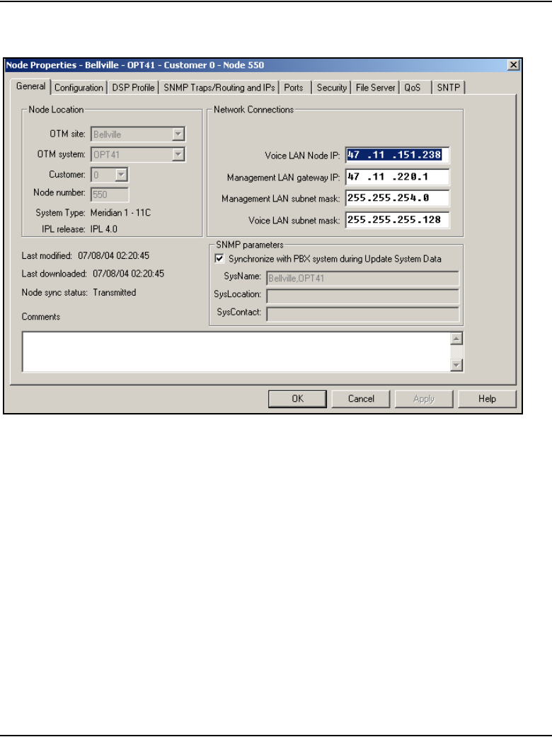
Page 662 of 910 IP Line administration using OTM 2.2
553-3001-365 Standard 4.00 August 2005
Figure 224
Node Properties – General tab
5Select the General tab.
See Figure 224.
Under Network Connections:
a. Voice LAN Node IP: This is also known as the TLAN subnet IP
address.
•Changing the node IP affects the configuration of the Connect
Server IP address in the DHCP Server for the IP Phones.
• If the IP Phones are using partial DHCP mode, manually
reconfigure the IP address in each IP Phone.

IP Line administration using OTM 2.2 Page 663 of 910
IP Line Description, Installation and Maintenance
b. Management LAN gateway IP: This IP address is used to route to
the ELAN subnet. If OTM is not connected to the local ELAN subnet,
then it communicates with this node through the Management LAN
gateway. If changes are made to the gateway IP address and these
changes are not coordinated properly, OTM loses communication
with the node:
• When a Management LAN gateway is added to the ELAN
subnet, the gateway must restrict access so that only authorized
traffic is permitted on the ELAN subnet.
• The router must disable the BootP relay agent for the ELAN
network interface.
• The router must block all broadcast and multicast traffic from the
ELAN subnet and enable only proper access; that is, only
authorized traffic and users can come through the Management
LAN gateway. OTM is one of these users.
c. Management LAN subnet mask: When changing these subnet
masks, consider the possibility of conflict between the ELAN and
TLAN network interface IP addresses. Consult with the IP
administrator before making any changes to network interfaces. See
“Codecs” on page 287.
When changing the Management LAN (ELAN) network interface, the
change must be coordinated with the IP address on the Call Server
(Active ELNK) subnet. Changes must also be coordinated with the
following:
• Management LAN gateway, and other IP devices on the ELAN
subnet (for example, OTM if it is local)
• any other devices on the ELAN subnet and the customer’s
enterprise network that could need to communicate with IP Line
• devices that are looking to receive SNMP traps
d. Voice LAN subnet mask: Coordinate with Voice LAN gateway
(router). When changing the Voice LAN (TLAN) network interface
subnet mask, the change must be coordinated with changing the
subnet mask of the Voice LAN (TLAN) gateway (router) network
interface.
6Click Apply.
7Select the Configuration tab.
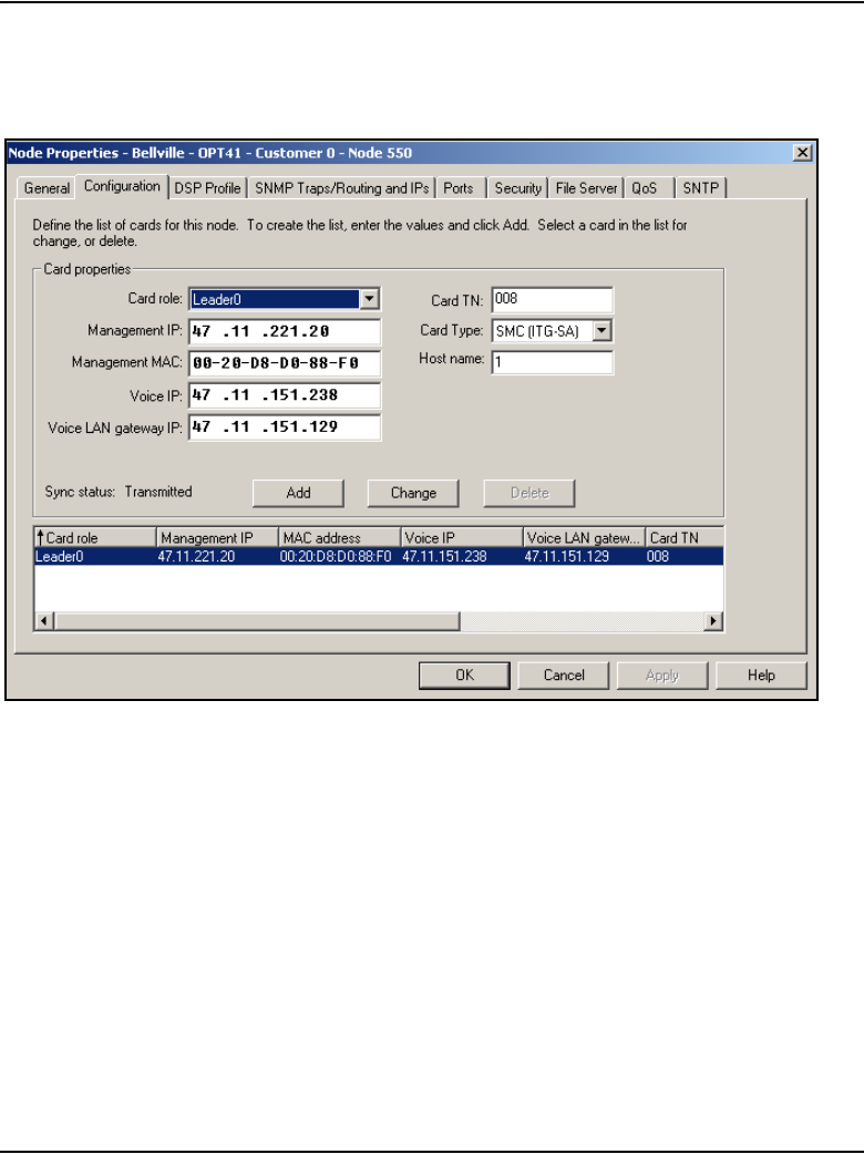
Page 664 of 910 IP Line administration using OTM 2.2
553-3001-365 Standard 4.00 August 2005
See Figure 225.
Figure 225
Node Properties – Configuration tab
8Select the card to be changed from the list at the bottom of the
Configuration tab.
9Under Card Properties:
a. Card Role: The first card in the node must be Leader 0.
Each IP Telephony node can have only one Leader 0. All other cards
function as Followers. OTM, however, requires that the first Follower

IP Line administration using OTM 2.2 Page 665 of 910
IP Line Description, Installation and Maintenance
be configured as Leader 1 even though it has no Leader functions.
The remaining cards are configured as Followers.
b. Management IP: If changing the Management IP address of
Leader 0, it is necessary Telnet to the card and use the setLeader
command to make the same change (new Management IP address)
in the NVRAM of the Leader 0 card.
Leader 0 must be reset for OTM to resume communication with the
node.
Note: Before resetting Leader 0, unplug all the other cards to prevent
any other card from becoming the Master. When Leader 0 restarts, plug
the cards back in. These other cards receive their new configuration from
Leader 0.
c. Management MAC: All other IP configuration depends on the
accurate configuration of the Management MAC address. The MAC
address is located on the faceplate of the Voice Gateway Media Card
and is labelled as MOTHERBOARD Ethernet address. The
Management MAC address corresponds to the ELAN network
interface address.
d. Voice IP: This is the card Voice IP address. This address is also
known as the card TLAN network interface IP address. In an IP
Telephony node, all cards must be assigned an address on the same
TLAN subnet. The card Voice IP address must be distinct from the
node IP address.
e. Voice LAN gateway IP: All cards in the IP Telephony node must be
on the TLAN subnet; therefore they all share the same Voice LAN
(TLAN) gateway IP address.
f. Card TN: The Card TN format must match both the machine type
and the card slot where the card resides. Otherwise, the voice
gateway channels do not function.
If trying to change the card TN format, first record the node
configuration data. Delete the node. Change the card TN format to
the correct machine, and rebuild the node.
For Large Systems, enter Card TN (l s c) information. For Small
Systems, enter only the card slot number between 1 – 50. The card
TN format is determined by the system type which is configured in the
OTM navigator. The correct system type must be entered in the OTM
Navigator before adding the node.
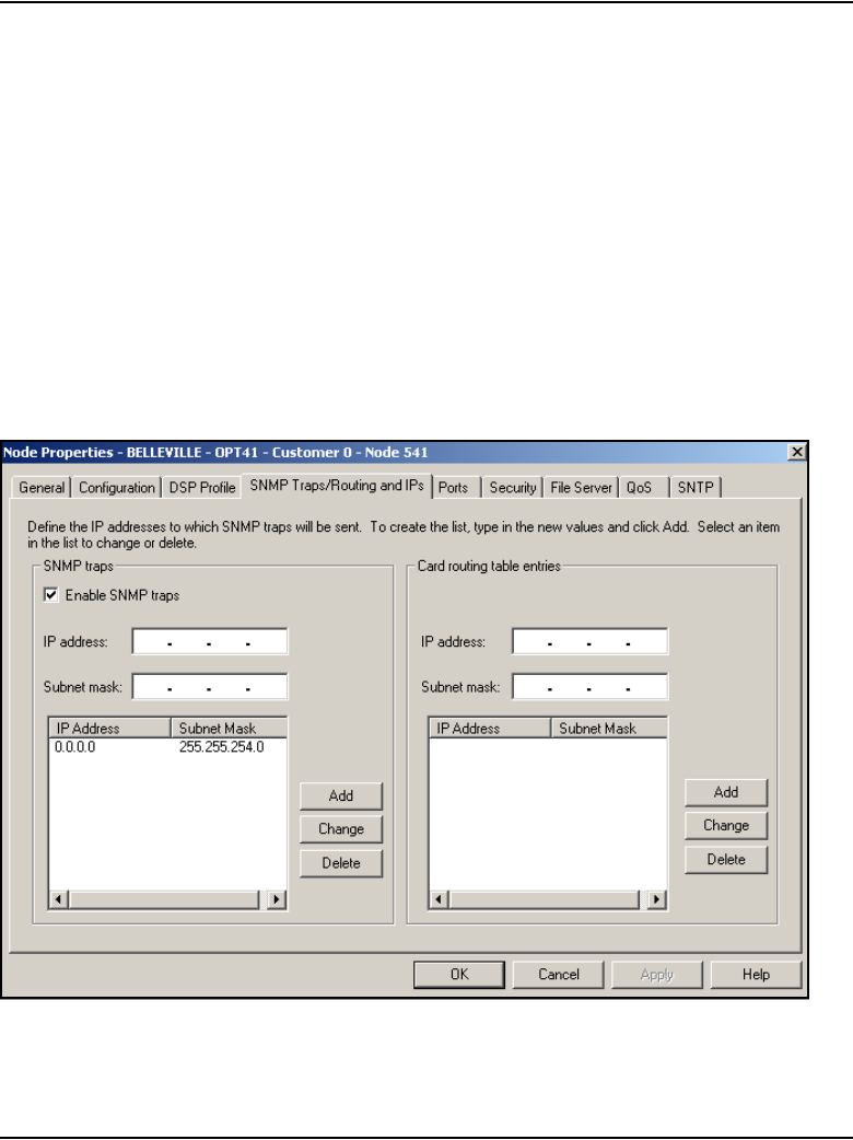
Page 666 of 910 IP Line administration using OTM 2.2
553-3001-365 Standard 4.00 August 2005
g. Card Type: Select Pentium for the ITG-P 24-port line card or
Strong Arm for the Media Cards.
10 For each card:
a. Click the Change button. The changes are reflected in the
working list at the bottom of the tab.
b. Then click Apply to save the changes to the card in the
database.
Select the next card to be changed from the working list at the bottom of
the tab. Make the appropriate changes, and then repeat the previous
steps.
11 Select the SNMP Traps/Routing and IPs tab. See Figure 226.
Figure 226
Node Properties – SNMP Traps/Routing and IPs tab

IP Line administration using OTM 2.2 Page 667 of 910
IP Line Description, Installation and Maintenance
Changes can be made to the SNMP Traps and Card routing table entries
without affecting other IP addresses. Change the SNMP traps and Card
routing table entries as required, based on the trap destination to be
reached.
IP addresses that are added in this tab create special card routing tables
that direct packets out the ELAN network interface and ELAN gateway.
Exercise caution when adding entries as the entry could result in one-way
voice transmission, if a change results in voice packets being streamed
out the ELAN network interface instead of the TLAN network interface.
Under SNMP Traps, up to eight SNMP trap destinations can be defined.
Under Card routing table entries, use caution when assigning card
routing table entries. Do not include the IP address of an IP Phone.
Otherwise, voice traffic to these IP Phones is incorrectly routed through
the ELAN and ELAN gateway. To avoid including the wrong IP address,
Nortel recommends that Host IDs be defined for the card routing table
entries.
12 Click Apply if any changes are made on the SNMP Traps/Routing and
IPs tab.
13 Select the Ports tab. See Figure 227 on page 668.
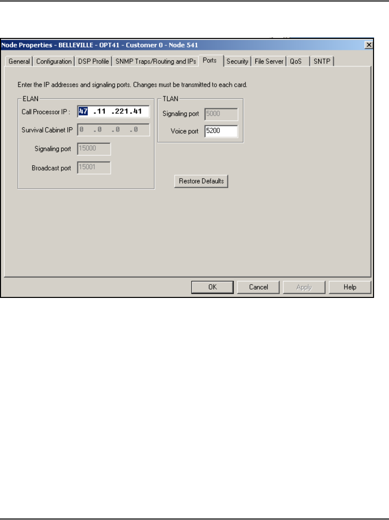
Page 668 of 910 IP Line administration using OTM 2.2
553-3001-365 Standard 4.00 August 2005
Figure 227
Node Properties – Ports tab
Under ELAN:
a. Call Processor ID: A change to this IP address must be coordinated
with the Call Server (Active ELNK) network interface.
b. Survival Cabinet IP: If applicable, enter the Survivable Cabinet
ELAN IP address (Active ELNK). The Survivable Cabinet IP is
enabled only for Small Systems.
Note: For Small Systems, this field is disabled unless at least one
cabinet has been defined in OTM Navigator as a Survivable Cabinet of
the main system. Each node has only one Survivable Cabinet IP address.
The Survivable Cabinet is equipped with sufficient trunk cards and Voice
Gateway Media Cards. In case of Call Server equipment failure, the
Survivable Cabinet provides a large degree of survivability for IP Phone
users.
c. Signaling port: This field is read-only.

IP Line administration using OTM 2.2 Page 669 of 910
IP Line Description, Installation and Maintenance
d. Broadcast port: This field is read-only.
Under TLAN:
a. Signaling port: This field is read-only.
b. Voice port: This field displays the range for RTP packets sent to the
IP Phones. In general, use the default value of 5200. If, however,
numerous IP Phones are working over low bandwidth WAN links
using CISCO RTP header compression, then change the voice port
to a number in the range of 16384 to 32767. Coordinate this value
change with the IP network administrator.
14 Click Apply.
15 When all updates to the IP addresses have been made, click OK in the
Node Properties window.
16 Unplug all the Voice Gateway Media Cards, except Leader 0.
Leader 0 receives its configuration from the BOOTP.TAB file.
17 Plug in all the cards.
Leader 0 forces its configuration to all the other cards.

Page 670 of 910 IP Line administration using OTM 2.2
553-3001-365 Standard 4.00 August 2005
18 Transmit the node or card properties to the Leader 0 card.
Select the Leader 0 Voice Gateway Media Card in the IP Telephony
window.
19 Click the Configuration > Synchronize > Transmit.
20 To transmit to the node, select the Transmit to selected nodes radio
button. Check the Node Properties to Active Leader check box.
21 Click the Start transmit button.
The results of the transmit appear in the box under Transmit control.
Verify that the properties are transmitted successfully. If the transmit is
unsuccessful, click the Start transmit button again.
22 Log into LD 32 and disable the cards using the DISI command.
23 Click the Configuration > Synchronize > Transmit.
24 Select the Transmit to select cards radio button.
25 Click the Start transmit button.
The results of the transmit appear in the box under Transmit control.
Verify that the properties transmitted successfully. If the transmit is
unsuccessful, click the Start transmit button again.
26 Click Close when the properties are successfully transmitted.
End of Procedure
If changes are made to the
__________ tab...
... then transmit
___________ properties.
General tab
Note: If changes are made to the
System Name, System Location, or
System Contact in the Hostname
Config window (Host Names button),
the card properties must be
transmitted.
node properties
Configuration tab node properties
SNMP Traps/Routing and IPs tab card properties
Ports tab card properties

IP Line administration using OTM 2.2 Page 671 of 910
IP Line Description, Installation and Maintenance
If the IP addresses of a single card have changed, the card must be restarted
for the changes to take effect. See “Restart a Voice Gateway Media Card” on
page 671. However, if IP addresses that affect the entire node have been
changed, then all cards in the node must be restarted. See “Restart all Voice
Gateway Media Cards” on page 672.
Restart a Voice Gateway Media Card
If the IP address of a Voice Gateway Media Card has changed, restart that
card only. Follow the steps in Procedure 97.
Procedure 97
Restarting a Voice Gateway Media Card
1To prevent interruption to the speech path, log into LD 32. Type the DISI
command.
This command disables the voice gateway channels when they become
idle. DISI removes the call traffic but does not remove the IP Phones that
are registered on that Voice Gateway Media Card. The Graceful TPS
Disable command disiTPS does that.
2Type disiTPS at the card’s IPL> prompt to disable the LTPS service on
the Voice Gateway Media Card.
This Graceful TPS Disable command prevents new IP Phones from
registering on the card. All IP Phones registered on the card are
re-directed to another Voice Gateway Media Card when the IP Phone
becomes idle.
After the command is entered, an idle IP Phone is supposed to be
updated with the Watchdog reset message. However, the LTPS sends a
soft reset message to the IP Phone, redirecting it to the Connect Server.
The disabled LTPS does not accept new registrations, so the IP Phone
must register with another LTPS in the node. Eventually, as all of the IP
Phones on the LTPS become idle, they are registered with other LTPSs.
The Voice Gateway Media Card can then be restarted with no impact to
any users.
End of Procedure

Page 672 of 910 IP Line administration using OTM 2.2
553-3001-365 Standard 4.00 August 2005
Restart all Voice Gateway Media Cards
All Voice Gateway Media Cards cards have to be restarted if there has been
a change to one of the following:
• node IP address – these changes affect the whole node and, as a result, all
cards must be restarted
• network interface of either the TLAN or ELAN (by changing the subnet
mask or the fields of the IP address) – if the Management (ELAN)
network interface IP address of Leader 0 has changed, all cards have to
be restarted. Even though this is a change to a single card, this change
affects all cards, as OTM uses this address to transmit properties to the
node.
Follow the steps in Procedure 98 to restart all the Voice Gateway Media
Cards.
Procedure 98
Restarting all the Voice Gateway Media Cards
1Telnet to the card from OTM.
2Use the setLeader command to set the new IP address.
Leader 0 uses this new IP address when it reboots.
3Reboot the Leader 0 using the cardReset command.
The Leader 0 card reads the new IP address from NVRAM.
4Restart all the other cards.
End of Procedure

IP Line administration using OTM 2.2 Page 673 of 910
IP Line Description, Installation and Maintenance
Update Voice Gateway Media Card card properties
Some basic Voice Gateway Media Card configuration must be performed
from the Node Properties window. To update the card properties in the DSP
Profile, follow the steps in Procedure 99.
Procedure 99
Updating card properties – DSP Profile tab
1In the OTM Navigator window, click the Services folder. Double-click the
IP Telephony icon.
The IP Telephony window opens.
2Click Configuration > Node > Properties.
3Click the DSP Profile tab.
The DSP Options sub-tab appears.
See Figure 228 on page 674.
CAUTION
This procedure is not supported for a node that resides
on a CS 1000 system.
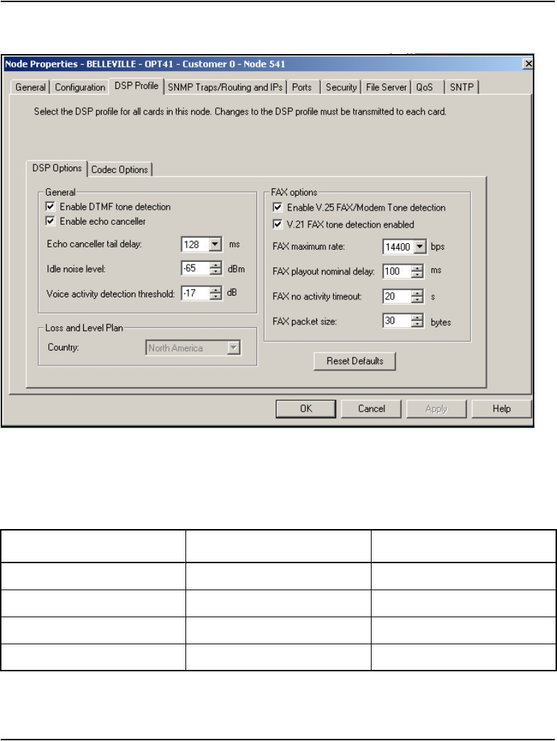
Page 674 of 910 IP Line administration using OTM 2.2
553-3001-365 Standard 4.00 August 2005
Figure 228
Node Properties – DSP Profile tab - DSP Options sub-tab
Table 78 lists the configurable DSP parameters, the range of the values,
and the default values.
Table 78
DSP parameters (Part 1 of 2)
Parameter Range Default value
Enable DTMF tone detection checked or unchecked checked
Enable echo canceller checked or unchecked checked
Echo canceller tail delay 64 or 128 ms 128 ms
Idle noise level –327 to +327 dB –65

IP Line administration using OTM 2.2 Page 675 of 910
IP Line Description, Installation and Maintenance
4Click the Codec Options sub-tab. See Figure 229 on page 677.
Up to four codecs can be selected.
Note: The T.38 Fax and G.711 Clear Channel Fax codecs are not
counted in this limit.
The G.711 codec type is mandatory and is automatically selected.
5Under Codec Options, the following parameters are user-configurable
on a per-codec basis:
Note: Leave the values at their default settings unless directed to change
them as follows or by Nortel Field Support.
a. Law type: The law type is applicable to G.711 only. The default is
mu-law.
b. Voice Activity Detection: The default is VAD disabled.
The VAD value is stored in the Config.ini file under the entry
VadEnabled=
VAD is not supported for G.711.
Voice activity detection
threshold
–20 to +10 dB –17 dB
Enable V.25 FAX/Modem
tone detection
checked or unchecked checked
Enable V.21 FAX tone
detection
checked or unchecked checked
FAX maximum rate 2400, 4800, 7200, 9600,
12000, 14400 bps
14400 bps
FAX playout nominal delay 0 – 300 ms 100 ms
FAX no activity timeout 10 – 32000 seconds 20 seconds
FAX packet size 20 – 48 bytes 30 bytes
Table 78
DSP parameters (Part 2 of 2)
Parameter Range Default value

Page 676 of 910 IP Line administration using OTM 2.2
553-3001-365 Standard 4.00 August 2005
c. Voice payload size: The default is the maximum supported. This
parameter is not configurable for the following:
• G.723.1
•T.38 Fax
• G.711 Clear Channel Fax
The payload size is stored in the Config.ini file under the entry
VxPayload=
d. Voice playout nominal delay (nominal jitter buffer)
Voice playout maximum delay (maximum jitter buffer)
The default values and the range of allowed values are displayed in
the drop-down lists.
6Click OK.
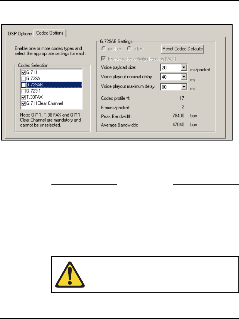
IP Line administration using OTM 2.2 Page 677 of 910
IP Line Description, Installation and Maintenance
Figure 229
ITG Node Properties – DSP Profile tab - Codec Options sub-tab with G.729 AB codec selected
Note: If there are multiple nodes on a system and the same codec is
selected on more than one node, ensure that each node has the same
voice payload size configured for the codec.
End of Procedure
As a result of the Run-time Configuration Change feature, the card does not
have to be restarted if there are changes to the settings on the DSP Profile tab.
For changes to the Codec Options, disable the card, download the card
properties, and then re-enable the card.
If the settings have changed on the DSP Profile tab, follow the steps in
Procedure 100 to disable and then enable the Voice Gateway Media Card.
CAUTION
This procedure is not supported for a node that resides
on a CS 1000 system.

Page 678 of 910 IP Line administration using OTM 2.2
553-3001-365 Standard 4.00 August 2005
Changes to the DSP Profile tab settings are applied immediately when the
card properties are transmitted.
Procedure 100
Disabling and re-enabling the Voice Gateway Media Card
1Log into LD 32 on the Call Server and use the DISI command to disable
the Voice Gateway Media Card.
2In the OTM Navigator window, click the Services folder. Double-click the
IP Telephony icon.
The IP Telephony window opens.
3Select the IP Telephony node from the list in the upper part of the main
window.
All Voice Gateway Media Cards in the node are displayed in the lower part
of the window.
4Select the node from the node list and press function key F5 or View >
Refresh > Selected to refresh the card status of all cards in the selected
node.
5In the IP Telephony window, click the Configuration menu option and
then select Synchronize > Transmit.
The Transmit Options window appears.
6Select the Transmit to selected cards radio button.
7Click the Start transmit button.
Verify that the transmit is successful under Transmit Control and then
click Close.
8Login to the Call Server and go to LD 32.
9Type the ENCL command to enable the Voice Gateway Media Card.
End of Procedure
IP Line administration using OTM 2.2 Page 679 of 910
IP Line Description, Installation and Maintenance
Retrieve command
The Retrieve command sends information from the Voice Gateway Media
Cards to the OTM IP Telephony node. The Retrieve command is used for the
following:
• downloading a node or card configuration by a remote OTM user
Note: This can also be performed by using the “Add Node” command
and selecting the “Retrieve the active configuration from an existing
node” option.
• copying node information from one node to another
• restoring accidentally-changed OTM information, and downloading
information to a fictitious “dummy” node that has been created for this
purpose, in order to view the configuration of the Voice Gateway Media
Card and the IP Telephony node.
Follow the steps in Procedure 101 to use the Retrieve command.
Procedure 101
Using the Retrieve command
1In the OTM Navigator window, click the Services folder. Double-click the
IP Telephony icon.
The IP Telephony window opens.
2Select the card(s) from which to retrieve information.
3Click Configuration > Synchronize > Retrieve.
The Retrieve Options window opens. See Figure 230 on page 680.
CAUTION
This procedure is not supported for a node that resides
on a CS 1000 system.
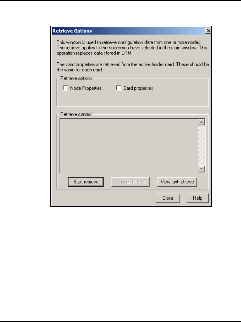
Page 680 of 910 IP Line administration using OTM 2.2
553-3001-365 Standard 4.00 August 2005
Figure 230
Retrieve Options window
4Under Retrieve Options, configure whether to retrieve Node properties
or Card properties by selecting one or more of the check boxes.
5Click Start Retrieve.
The results of the Retrieve command are displayed under Retrieve
control.
Note 1: If the Retrieve command is successful, the current configuration
of the node or card properties in OTM is overwritten by the configuration
data that was retrieved from the node. The new configuration data can be
viewed in the Node Properties window.

IP Line administration using OTM 2.2 Page 681 of 910
IP Line Description, Installation and Maintenance
Note 2: To view the configuration of a node without overwriting the
current node configuration in OTM, retrieve the information to a dummy
node.
End of Procedure
Add an IP Telephony node in OTM by retrieving an
existing node
Use this optional procedure in the following cases:
• to add existing nodes to a particular OTM PC to manage the
IP Telephony network from a single point of view
• to restore the IP Telephony configuration database to an OTM PC whose
hard drive has crashed, as an alternative to restoring the OTM IP
Telephony nodes from the OTM Disaster Recovery Backup
When the IP Telephony node is installed and configured manually, that node
can then be added to another OTM PC by retrieving the configuration data
from the existing IP Telephony node.
Configure the site name, system name, and customer number in the OTM
Navigator before adding a new IP Telephony node. Only one IP Telephony
node can be added in the OTM IP Line application for each system customer.
If multiple OTM PCs are used to manage the same IP Telephony network,
care must be taken to synchronize the different copies of the IP Telephony
database. The OTM Configuration > Synchronize > Retrieve function can
be used to synchronize the OTM IP Telephony database with the database on
the IP Telephony node.
CAUTION
This procedure is not supported for a node that resides
on a CS 1000 system.
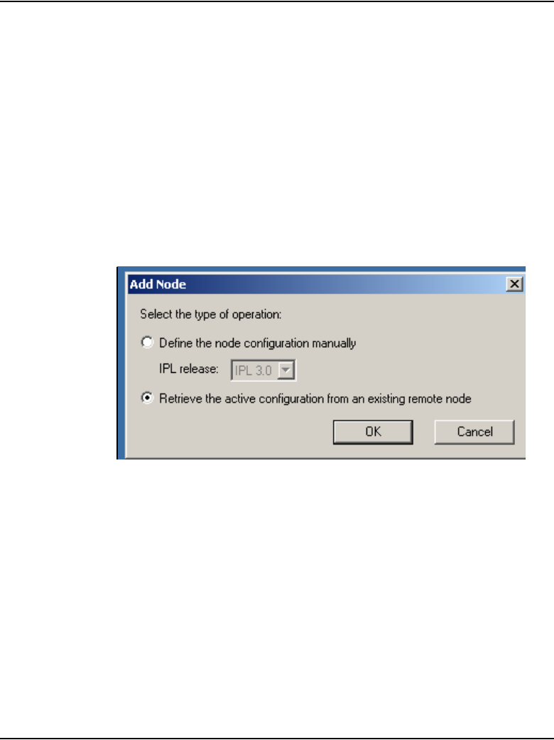
Page 682 of 910 IP Line administration using OTM 2.2
553-3001-365 Standard 4.00 August 2005
Follow the steps in Procedure 102 to add an IP Telephony node by retrieving
an existing node.
Procedure 102
Adding a node by retrieving an existing node
1In the OTM Navigator window, click the Services folder. Double-click the
IP Telephony icon.
The IP Telephony window opens.
2Click Configuration > Node > Add.
The Add Node dialog box opens. See Figure 231.
Figure 231
Add Node – Retrieve configuration from existing node
3Click the Retrieve the active configuration from an existing remote
node radio button, and then click OK.
The Retrieve node window opens. See Figure 232 on page 683.

IP Line administration using OTM 2.2 Page 683 of 910
IP Line Description, Installation and Maintenance
Figure 232
Retrieve node

Page 684 of 910 IP Line administration using OTM 2.2
553-3001-365 Standard 4.00 August 2005
4The OTM site name, OTM system name, and customer number must
exist in the OTM Navigator before a new IP Telephony node can be
added.
Note: Ensure the system type is defined correctly.
Under Node Location in the Retrieve node window:
a. OTM site: Select the OTM Site.
b. OTM system: Select the system.
c. Customer: Select the Customer number.
d. Node Number: Ensure the node number is unique under the
customer number. Also, ensure that all IP Telephony nodes
connected to the same TLAN subnet have a unique node number
regardless of the OTM site, Meridian 1 system, and customer
number.
e. Active leader management (ELAN) IP: Enter the active Leader
management IP address field for the existing node.
f. SNMP community read/write name: Enter the SNMP read/write
community name.
Note: The SNMP read community name cannot be used.
5Click Start retrieve.
The results of the retrieval are shown under Retrieve control. The node
properties are retrieved from the active Leader. The card properties are
retrieved from Leader 0.
6Click Close when the download is complete.
7In the IP Telephony window, select the newly added node in the top part
of the window.
8Refresh the card status (View > Refresh) and verify that the cards in the
newly added node are responding.
A new node has been created by retrieving data from another node
9Double-click on the new node in the IP Telephony window. The Node
Properties window opens for the newly-added node.
10 Inspect each tab in the node properties and verify the data is correct and
consistent with the node from which the data was retrieved.
IP Line administration using OTM 2.2 Page 685 of 910
IP Line Description, Installation and Maintenance
11 Click the Configuration tab and ensure the Host names information, IP
addresses, and TN are consistent.
End of Procedure
IP Line CLI access using Telnet or local RS-232
maintenance port
There are two ways to access the IPL> Command Line Interface (CLI):
1Use the NTAG81CA cable to connect the DIN8 pin connector on the
faceplate, or the NTAG81BA cable to connect the DB9 I/O breakout
cable to the COM port of a local PC. Use a null-modem adapter to
connect a modem for remote dial-up access.
2Telnet to the card from the OTM IP Telephony window. This
automatically Telnets to the IP address of the Management interface
(ELAN) of the card. Alternatively, use the Telnet application on a PC and
manually enter the Management (ELAN) IP address, Voice (TLAN) IP
address, or the node IP address if trying to connect to the active Leader.
Telnet to a Voice Gateway Media Card
To access the CLI on a Voice Gateway Media Card from the OTM PC, follow
the steps in Procedure 103.
Procedure 103
Accessing a Voice Gateway Media Card using Telnet
1Click the Services folder. Double-click the IP Telephony icon.
The IP Telephony window opens.
2Right-click on the Voice Gateway Media Card to be accessed.
3Select Telnet to ITG card from the popup menu.
CAUTION
Do not connect two maintenance terminals to both
the faceplate and I/O panel serial maintenance port
connections at the same time.

Page 686 of 910 IP Line administration using OTM 2.2
553-3001-365 Standard 4.00 August 2005
The OTM PC opens a Telnet window and automatically connects to the
Voice Gateway Media Card by using the Management (ELAN) IP
address.
4Enter a user name and password to access the IPL> CLI.
Both the default user name and password are itgadmin. However, for
security purposes, the user name and password should have been
changed during installation.
The IPL> prompt appears if the login is successful.
5Type ? at the prompt to display a list of available IPL> CLI commands.
See “IP Line CLI commands” on page 710 for a detailed list of commands.
End of Procedure

Page 687 of 910
IP Line Description, Installation and Maintenance
770
Voice Gateway Media Card maintenance
Contents
This section contains information on the following topics:
Introduction . . . . . . . . . . . . . . . . . . . . . . . . . . . . . . . . . . . . . . . . . . . . . . 688
Faceplate maintenance display codes . . . . . . . . . . . . . . . . . . . . . . . . . . 688
System error messages . . . . . . . . . . . . . . . . . . . . . . . . . . . . . . . . . . . . . 693
IP Line and IP Phone maintenance and diagnostics . . . . . . . . . . . . . . . 699
TNs . . . . . . . . . . . . . . . . . . . . . . . . . . . . . . . . . . . . . . . . . . . . . . . . . . 707
Maintenance commands for the IP Phone . . . . . . . . . . . . . . . . . . . . 708
IP Line CLI commands . . . . . . . . . . . . . . . . . . . . . . . . . . . . . . . . . . . . . 710
General purpose commands . . . . . . . . . . . . . . . . . . . . . . . . . . . . . . . 711
File transfer commands . . . . . . . . . . . . . . . . . . . . . . . . . . . . . . . . . . 715
IP configuration commands . . . . . . . . . . . . . . . . . . . . . . . . . . . . . . . 719
Reset commands. . . . . . . . . . . . . . . . . . . . . . . . . . . . . . . . . . . . . . . . 720
DSP commands . . . . . . . . . . . . . . . . . . . . . . . . . . . . . . . . . . . . . . . . 721
Upgrade commands . . . . . . . . . . . . . . . . . . . . . . . . . . . . . . . . . . . . . 721
IPL> shell commands. . . . . . . . . . . . . . . . . . . . . . . . . . . . . . . . . . . . 722
IP Phone Installer Password commands. . . . . . . . . . . . . . . . . . . . . . 723
Voice Gateway commands. . . . . . . . . . . . . . . . . . . . . . . . . . . . . . . . 726
Data Path Capture Tool commands . . . . . . . . . . . . . . . . . . . . . . . . . 727
Translation IP/DN commands . . . . . . . . . . . . . . . . . . . . . . . . . . . . . 728
Graceful TPS commands . . . . . . . . . . . . . . . . . . . . . . . . . . . . . . . . . 736
IP Phone Loss Plan (UK) commands . . . . . . . . . . . . . . . . . . . . . . . . 740
Patch and Patching Tool commands. . . . . . . . . . . . . . . . . . . . . . . . . 742
General trace tool commands . . . . . . . . . . . . . . . . . . . . . . . . . . . . . . 748
Protocol trace tool commands for the Network Connection Service 750

Page 688 of 910 Voice Gateway Media Card maintenance
553-3001-365 Standard 4.00 August 2005
Lamp Audit and Keep Alive functions . . . . . . . . . . . . . . . . . . . . . . . . . 752
Maintenance audit . . . . . . . . . . . . . . . . . . . . . . . . . . . . . . . . . . . . . . 752
Voice Gateway Media Card self-tests . . . . . . . . . . . . . . . . . . . . . . . . . 758
Troubleshoot a software load failure . . . . . . . . . . . . . . . . . . . . . . . . . . 758
Warm reboot of the Voice Gateway Media Card . . . . . . . . . . . . . . 760
Test the Voice Gateway Media Card DSPs . . . . . . . . . . . . . . . . . . . 760
Work with alarm and log files . . . . . . . . . . . . . . . . . . . . . . . . . . . . . 761
Troubleshoot an IP Phone installation . . . . . . . . . . . . . . . . . . . . . . . . . 761
Maintenance telephone . . . . . . . . . . . . . . . . . . . . . . . . . . . . . . . . . . . . . 762
Upgrade Voice Gateway Media Card firmware . . . . . . . . . . . . . . . . . . 763
Upgrade the ITG-P 24-port card firmware . . . . . . . . . . . . . . . . . . . 763
Upgrade the Media Card firmware . . . . . . . . . . . . . . . . . . . . . . . . . 766
Replace the Media Card’s CompactFlash. . . . . . . . . . . . . . . . . . . . . . . 769
Introduction
This chapter provides information on maintenance functions for the Voice
Gateway Media Card.
Note: Check the Nortel web site for information on the latest software,
firmware, and application releases.
Faceplate maintenance display codes
The Voice Gateway Media Card’s maintenance display provides the
diagnostic status of the card during power-up, its operational state when in
service, and error information on the functional state of the card.
• Table 79 on page 689 lists the normal and fault display codes for the
ITG-P 24-port line card.
• Table 80 on page 691 list the normal and fault display codes for the
Media Card 8-port and 32-port line card.

Voice Gateway Media Card maintenance Page 689 of 910
IP Line Description, Installation and Maintenance
During power-up, the card performs multiple self-tests, including an internal
RAM test, ALU test, address mode test, boot ROM test, timer test, and
external RAM test. If any of these tests fail, the card enters a maintenance
loop, and no further processing is possible. A failure message is printed on
the display to indicate which test failed. For example, if the timer test fails on
the ITG-P 24-port line card, F:05 is displayed.
If the other tests fail (up to and including the EEPROM test), a message is
displayed for three seconds. If more than one test fails, the message displayed
indicates the first failure. If verbose mode has been selected (by the test input
pin on the backplane), the three-second failure message is not displayed.
If the maintenance display on the ITG-P 24-port line card shows a persistent
T:20 indicating an IP Line 4.5 software failure, and if this occurs after the
card was reset during a loadware download procedure, call Nortel technical
support for assistance in attempting to download new software onto the card.
Table 79
ITG-P 24-port line card faceplate maintenance display codes
(Part 1 of 2)
Normal code Fault code Message
T:00 F:00 Initialization
T:01 F:01 Testing Internal RAM
T:02 F:02 Testing ALU
T:03 F:03 Testing address modes
T:04 F:04 Testing Boot ROM
T:05 F:05 Testing timers
T:06 F:06 Testing watchdog
T:07 F:07 Testing external RAM
T:08 F:08 Testing Host DPRAM
T:09 F:09 Testing DS30 DPRAM
T:10 F:10 Testing Security Device

Page 690 of 910 Voice Gateway Media Card maintenance
553-3001-365 Standard 4.00 August 2005
T:11 F:11 Testing Flash memory
T:12 F:12 Programming PCI FPGA
T:13 F:13 Programming DS30 FPGA
T:14 F:14 Programming CEMUX FPGA
T:15 F:15 Programming DSP FPGA
T:16 F:16 Testing CEMUX interface
T:17 F:17 Testing EEPROM
T:18 F:18 Booting processor, waiting for response
with self-test information.
T:19 F:19 Waiting for application start-up
messages from processor.
T:20 CardLAN enabled, transmitting BootP
requests. If this display persists, then
the ITG-P 24-port line card is running in
BIOS ROM mode due to card software
failure.
T:00 F:00 Initialization
T:01 F:01 Testing Internal RAM
T:02 F:02 Testing ALU
T:03 F:03 Testing address modes
Table 79
ITG-P 24-port line card faceplate maintenance display codes
(Part 2 of 2)
Normal code Fault code Message

Voice Gateway Media Card maintenance Page 691 of 910
IP Line Description, Installation and Maintenance
If a test fails on the Media Card, F:XX appears on the Hex display for three
seconds after T:13 message (Testing SEEPROM). For example, if the 8051
co-processor test failed, F:05 is displayed on the Media Card faceplate. If
more that one test fails, the message indicates the first failure
Table 80
Media Card faceplate maintenance display codes (Part 1 of 2)
Normal code Fault code Message
T:00 F:00 Initialization
T:01 F:01 Testing Internal RAM
T:02 F:02 Testing ALU
T:03 F:03 Testing address modes
T:04 F:04 Testing watchdog
T:05 F:05 Testing 8051 co-processor
T:06 F:06 Testing timers
T:07 F:07 Testing external RAM
T:08 F:08 Testing dongle
T:09 F:09 Programming timeswitch FPGA
T:10 F:10 Programming ISPDI FPGA
T:11 F:11 Testing host dual port RAM
T:12 F:12 Testing DS-30 dual port RAM
T:13 F:13 Testing SEEPROM
T:14 F:14 Booting Host processor, waiting for
response with selftest information
T:15 F:15 Not used at present
T:16 F:16 Not used at present
T:17 F:17 Not used at present
T:18 F:18 Not used at present

Page 692 of 910 Voice Gateway Media Card maintenance
553-3001-365 Standard 4.00 August 2005
If the IXP encounters any failures during its initialization, an H:XX error code
is displayed. Table 81 shows the list of error codes.
T:19 F:19 Not used at present
T:20 F:20 Waiting for application start-up message
from Host processor
T:21 F:21 CardLAN enabled, waiting for request
configuration message
T:22 F:22 CardLAN operational, A07 enabled,
display now under host control
Table 81
List of error codes for the Media Card
Code Description
H:00 Host Processor not booting
H:01 SDRAM test failure
H:02 SRAM test failure
H:04 PC Card device failure
H:08 Network interface failure
H:10 Meridian 1 interface failure
H:20 DSP interface failure
H:40 NVRAM/EEPROM interface failure
H:80 PCM connector failure
Table 80
Media Card faceplate maintenance display codes (Part 2 of 2)
Normal code Fault code Message

Voice Gateway Media Card maintenance Page 693 of 910
IP Line Description, Installation and Maintenance
System error messages
When an error or specific event occurs, SNMP sends an alarm trap to OTM
or any SNMP manager that is configured in the SNMP Manager’s list in the
ITG Card properties. System error message are also written to the error log
file containing error messages.
View the error log in OTM IP Line 4.5 by clicking the Open Log File button
on the Maintenance tab of the ITG Card Properties. Alternatively, view the
log file in any text browser after uploading it to an FTP host using the
LogFilePut command.
ITG and ITS messages incorporate the severity category of the message in the
first digit of the four digit number. Message numbers beginning with 0 do not
follow this format.
1 = Critical
2 = Major
3 = Minor
4 = Warning
5 = Cleared (Info)
6 = Indeterminate (Info)
Error messages with a severity category of “Critical” are displayed on the
Voice Gateway Media Card’s maintenance faceplate display in the form:
“Gxxx” or “Sxxx”, where xxx is the last three digits of the ITG or ITS
message. The Signaling Server does not have a faceplate display. Alarms
appear in the Signaling Server 's report log or by way of SNMP on an Alarm
browser.

Page 694 of 910 Voice Gateway Media Card maintenance
553-3001-365 Standard 4.00 August 2005
Table 82 lists the critical ITG messages and Table 83 on page 697 lists the
critical ITS messages.
All listed alarms can be sent by a Voice Gateway Media Card. Any alarm that
can be sent by the Signaling Server has an “X” in the column labeled
“Signaling Server.”
For a complete listing of other error messages, see Software Input/Output:
System Messages (553-3001-411).
Table 82
Critical ITG Error messages (Part 1 of 4)
Maintenance
Display
Corresponding
Critical
Error Message
Signaling
Server Description
G000 ITG1000 XCard (re)booted.
G001 ITG1001 XTask spawn failure <name>.
G002 ITG1002 XMemory allocation failure.
G003 ITG1003 XFile IO error <operation> <object>
<errno> <errtext>.
G004 ITG1004 XNetwork IO error <operation> <object>
<errno> <errtext>.
G005 ITG1005 XMessage queue error <operation>
<object> <errno> <errtext>.
G006 ITG1006 XUnexpected state encountered <file>
<line> <state>.
G007 ITG1007 XUnexpected message type <file> <line>
<msg>.
G008 ITG1008 XNull pointer encountered <file> <line>
Name of pointer.
G009 ITG1009 XInvalid block <file> <line> Type of block.

Voice Gateway Media Card maintenance Page 695 of 910
IP Line Description, Installation and Maintenance
G010 ITG1010 XUnable to locate data block <file> <line>
Type of block.
G011 ITG1011 XFile transfer error: <operation> <file>
<host>
G012 ITG1012 XModule initialization failure:
<moduleName>
G013 ITG1013 Ethernet receiver buffer unavailable,
packet(s) discarded.
G014 ITG1014 XEthernet carrier: <ifName> <state>
G015 ITG1015 Ethernet device failure: <ifName>
G017 ITG1017 XInvalid or unknown SSD message:
<ssdType> <TN> <msg>
G019 ITG1019 DSP channel open failure <channel>.
G020 ITG1020 XConfiguration error <param> <value>
<reason>.
G021 ITG1021 DSP successfully reset <dsp>.
G022 ITG1022 DSP channel not responding, channel
disabled <channel>.
G023 ITG1023 DSP device failure: <dsp> <errnum>
<errtext>
G025 ITG1025 DSP download: <dsp> <reason>
G027 ITG1027 DSP memory test: <dsp> <reason>
G028 ITG1028 XVoice packet loss: <channel>
<%packetLoss> <direction> <dstAddr>
Table 82
Critical ITG Error messages (Part 2 of 4)
Maintenance
Display
Corresponding
Critical
Error Message
Signaling
Server Description

Page 696 of 910 Voice Gateway Media Card maintenance
553-3001-365 Standard 4.00 August 2005
G029 ITG1029 Error in DSP task <file> <line> <errno>
<errtext>.
G030 ITG1030 Allocation failure in DSP memory pool.
G031 ITG1031 XInvalid codec number: <Codec>
G032 ITG1032 Attempt to open a DSP that is already
open: <channel>
G033 ITG1033 Failed to send data to DSP channel:
<channel>
G034 ITG1034 DSP channel unexpectedly closed:
<channel>
G035 ITG1035 Encountered and unexpected open DSP
channel, closed it: <channel>
G037 ITG1037 Wrong image downloaded. Binary was
created for <cardType> card.
G038 ITG1038 IPL login protection (login
available/locked)
G039 ITG1039 Bad DSP channel <channel id>
G040 ITG1040 Last reset reason for card:
<reasonString> where the reason String
can be: Reboot command issued (by
software or through CLI); Watchdog
Timer Expired; Manual reset; Internal XA
problem; or Unknown
Table 82
Critical ITG Error messages (Part 3 of 4)
Maintenance
Display
Corresponding
Critical
Error Message
Signaling
Server Description

Voice Gateway Media Card maintenance Page 697 of 910
IP Line Description, Installation and Maintenance
G041 ITG1041 XperceivedSeverity =
alarmSeverityWarning
probableCause =
alarmCauseRemoteTransmissionError
OTM displays the text “F/W file(s) not
received but IP Phones have registered.
May have mixed F/W versions across
phones. When F/W file(s) received, IP
Phones will automatically be updated.”
G042 ITG1042 perceivedSeverity =
alarmSeverityWarning
probableCause =
alarmCauseOutOfMemory
OTM displays the text “Insufficient flash
drive space to store F/W file.”
Table 83
Critical ITS Error messages (Part 1 of 2)
Maintenance
Display
Corresponding
Critical
Error Message
Signaling
Server Description
S000 ITS1000 XVTI function call time-out.
S001 ITS1001 XUser terminal registration failed. <ip>
<hwid> <errno> <errtext>.
S002 ITS1002 XConnect service activation error <reason>.
S003 ITS1003 XDuplicate master <node> <ip1> <ip2>.
Table 82
Critical ITG Error messages (Part 4 of 4)
Maintenance
Display
Corresponding
Critical
Error Message
Signaling
Server Description

Page 698 of 910 Voice Gateway Media Card maintenance
553-3001-365 Standard 4.00 August 2005
S004 ITS1004 XInvalid node ID <ip> <hwid>.
S005 ITS1005 XCorrupted node ID/TN field <ip> <hwid>.
S006 ITS1006 XReceived corrupted UNIStim message
<message dump>.
S007 ITS1007 XReceived unknown UNIStim message
<message dump>.
S008 ITS1008 XTerminal connection status: <ip> <status>.
S009 ITS1009 XCall Server communication link:<state>.
S010 ITS1010 XTerminal doesn't support codec:
<ip><Codec>.
S011 ITS1011 X<IP Address>: Last reset reason for IP
Phone: <reasonID> (<reasonString>)
S012 ITS1012 XUser entered the wrong IP Phone Installer
Password three times during Branch User
Config.The IP Phone is locked out from
doing any User Configuration for one hour.
Action: Wait for the IP Phone to unlock in
one hour, or use the IPL CLI command
clearLockout to unlock the IP Phone.
S013 ITS1013 XUser entered the wrong Craftsperson Node
Level TN Entry Password three times.The
IP Phone is locked out.
Action: To remove the lock, use LD 32 to
disable, and then enable the IP Phone.
Table 83
Critical ITS Error messages (Part 2 of 2)
Maintenance
Display
Corresponding
Critical
Error Message
Signaling
Server Description

Voice Gateway Media Card maintenance Page 699 of 910
IP Line Description, Installation and Maintenance
IP Line and IP Phone maintenance and
diagnostics
LD 32
Table 84 on page 700 summarizes the system maintenance commands
available in LD 32.
The following ECNT commands are also now available in LD 117, as well as
in LD 32:
• ECNT CARD
• ECNT NODE
•ECNT SS
• ECNT ZONE
As well, the following ECNT commands are available in LD 117:
•ECNT FW
• ECNT MODL
•ECNT PEC
For more information on the ECNT commands, refer to “Counting IP
Phones” on page 214 and “LD 117” on page 703.

Page 700 of 910 Voice Gateway Media Card maintenance
553-3001-365 Standard 4.00 August 2005
Table 84
LD 32 – Maintenance commands for the Voice Gateway Media Card (Part 1 of 4)
Command Description
DISC l s c Disable the specified card,
where: l = loop, s = shelf, c = card.
Note 1: Disable the Voice Gateway Media Card before transmitting card
properties from the OTM IP Line 4.5 application.
Note 2: The card reset button is available only in the OTM IP Line 4.5
application when the card is disabled.
Note 3: When the Voice Gateway Media Card is disabled in LD 32, it
does not disable the active Leader or backup Leader functions.
DISI l s c Disable the specified card when idle,
where: l = loop, s = shelf, c = card
Note 1: This temporarily prevents the IP Telephony node from seizing
the port from incoming calls.
Note 2: Use the DISI command to disable the Voice Gateway Media
Card instead of the DISC command. The disabled state of the Voice
Gateway Media Card is indicated by the NPR0011 message.
DISU l s c u Disable the specified unit,
where: l = loop, s = shelf, c = card, u = unit

Voice Gateway Media Card maintenance Page 701 of 910
IP Line Description, Installation and Maintenance
ECNT CARD L S
C <customer>
Counts and prints the number of IP Phones registered for the specified
card.
• If the <customer> parameter is specified, the count is specific to that
customer. A card must be specified to enter a customer; otherwise, the
count is across all customers.
• If no parameters are entered, the count is printed for all zones. A partial
TN can be entered for the card (L or L S) which then prints the count
per that parameter. A customer cannot be specified in this case.
Example:
ECNT CARD 81
<< Card 81 >>
Number of Registered Ethersets: 5
Number of Unregistered Ethersets: 27
ECNT ZONE
zoneNum
<customer>
Counts and prints the number of IP Phones registered for the specified
zone.
• If <customer> parameter is specified, the count is specific to that
customer. A zone must be specified to enter a customer; otherwise, the
count is across all customers.
• If no parameters are entered, the count is printed for all zones.
Example:
ECNT ZONE 0 0
<< Zone 0 Customer 0 >>
Number of Registered Ethersets: 4
Number of Unregistered Ethersets: 17
Table 84
LD 32 – Maintenance commands for the Voice Gateway Media Card (Part 2 of 4)
Command Description

Page 702 of 910 Voice Gateway Media Card maintenance
553-3001-365 Standard 4.00 August 2005
ECNT NODE
nodeNum
Counts and prints the number of IP Phones registered for the specified
node.
• If the nodeNum parameter is not entered, the count is printed for all
nodes.
Example:
ECNT NODE 8765
<< Zone 8765 >>
Number of Registered Ethersets: 3
ECNT SS
<hostName>
Counts and prints the number of IP Phones registered for the specified
Signaling Server.
• If hostName parameter is not entered, the count is printed for all
Signaling Servers.
Example:
ECNT SS
<< Signaling Server: BVWAlphaFox IP 10.10.10.242>>
Number of Register Ethersets: 1000
Note: If the hostName variable contains an underscore (_), then an
NPR001 error message is returned, as an underscore is considered to be
an invalid character.
ENLC l s c Enable the specified card,
where: l = loop, s = shelf, c = card
ENLU l s c u Enable the specified unit,
where: l = loop, s = shelf, c = card, u = unit
IDC l s c Print the Card ID information for the specified card,
where: l = loop, s = shelf, c = card
Note 1: This command displays the PEC (Product Engineering Code)
and serial number for the card. The IP Line PEC is NTZC80AA.
Table 84
LD 32 – Maintenance commands for the Voice Gateway Media Card (Part 3 of 4)
Command Description

Voice Gateway Media Card maintenance Page 703 of 910
IP Line Description, Installation and Maintenance
LD 117
Table 85 on page 704 summarizes the system maintenance commands
available in LD 117.
The following ECNT commands are also maintained in LD 32:
• ECNT CARD <Loop> <Shelf> <Card> <CustomerNumber>
• ECNT NODE <NodeNumber>
• ECNT SS <HostName>
• ECNT ZONE <ZoneNumber> <CustomerNumber>
STAT l s c Print the Meridian 1/CS 1000 software status of the specified card,
where: l = loop, s = shelf, c = card
STAT l s c u Print the Meridian 1/CS 1000 software status of the specified unit,
where: l = loop, s = shelf, c = card, u = unit
Table 84
LD 32 – Maintenance commands for the Voice Gateway Media Card (Part 4 of 4)
Command Description

Page 704 of 910 Voice Gateway Media Card maintenance
553-3001-365 Standard 4.00 August 2005
For more information on the ECNT commands, refer to “Counting IP
Phones” on page 214
Table 85
LD 117 – Count registered IP Phones (Part 1 of 4)
Command Description
ECNT CARD L S C
<customer>
Counts and prints the number of IP Phones registered for the specified
card.
• If the <customer> parameter is specified, the count is specific to that
customer. A card must be specified to enter a customer; otherwise,
the count is across all customers.
• If no parameters are entered, the count is printed for all zones. A
partial TN can be entered for the card (L or L S) which then prints the
count per that parameter. A customer cannot be specified in this
case.
Example:
ECNT CARD 81
<< Card 81 >>
Number of Registered Ethersets: 5
Number of Unregistered Ethersets: 27
ECNT ZONE
zoneNum
<customer>
Counts and prints the number of IP Phones registered for the specified
zone.
• If <customer> parameter is specified, the count is specific to that
customer. A zone must be specified to enter a customer; otherwise,
the count is across all customers.
• If no parameters are entered, the count is printed for all zones.
Example:
ECNT ZONE 0 0
<< Zone 0 Customer 0 >>
Number of Registered Ethersets: 4
Number of Unregistered Ethersets: 17

Voice Gateway Media Card maintenance Page 705 of 910
IP Line Description, Installation and Maintenance
ECNT NODE
nodeNum
Counts and prints the number of IP Phones registered for the specified
node.
• If the nodeNum parameter is not entered, the count is printed for all
nodes.
Example:
ECNT NODE 8765
<< Zone 8765 >>
Number of Registered Ethersets: 3
ECNT SS
<hostName>
Counts and prints the number of IP Phones registered for the specified
Signaling Server.
• If hostName parameter is not entered, the count is printed for all
Signaling Servers.
Example:
ECNT SS
<< Signaling Server: BVWAlphaFox IP 10.10.10.242>>
Number of Register Ethersets: 1000
Note: If the hostName variable contains an underscore (_), then an
NPR001 error message is returned, as an underscore is considered to
be an invalid character.
Table 85
LD 117 – Count registered IP Phones (Part 2 of 4)
Command Description

Page 706 of 910 Voice Gateway Media Card maintenance
553-3001-365 Standard 4.00 August 2005
ECNT FW <XX>
<A> <BB> <FF>
Prints the number of IP Phones with specified firmware ID and running
specified firmware version.
<XX> – firmware ID
<A> – major version designator
<BB> – minor version designator
<FF> – filter to apply on firmware version; can be one of the following:
= – equal to
~ – not equal to
< – less then
> – greater then
Only the XX parameter is mandatory.
ECNT FW <XX> <A> <BB> defaults to
ECNT FW <XX> <A> <BB> =
ECNT FW <XX> <A> counts all registered IP Phones with firmware ID
equal to <XX> and major version designator equal to <A>.
ECNT FW <XX> counts all registered IP Phones with firmware ID equal
to <XX>.
ECNT FW is equivalent to ECNT FW ALL; that is, the list containing
firmware IDs and the quantity of IP Phones with this firmware ID is
printed.
ECNT MODL
<MMMM>
Prints the number of IP Phones of specified model.
<MMMM> – specifies model name.
If this parameter is omitted, then a list of the model names and
associated mnemonics is printed.
Table 85
LD 117 – Count registered IP Phones (Part 3 of 4)
Command Description

Voice Gateway Media Card maintenance Page 707 of 910
IP Line Description, Installation and Maintenance
TNs
For Nortel IP Phones, there are two kinds of TNs to consider:
• physical TN – represents a physical unit of the Voice Gateway Media
Card
• virtual TN – configured on a virtual superloop and represents an IP
Phone
Physical TNs
Physical TNs, that are seen as trunk units, are managed using existing LD 32
commands.
Virtual TNs
Because virtual TNs are configured on a virtual superloop, virtual TN
maintenance has no meaning; that is, what is already provided by the
Meridian 1 and CS 1000 for phantom loops.
In LD 32, any command affecting a phantom loop leads to an NTP665
message because the loop does not physically exist. LD 32 supports STAT,
DISU, ENLU, and IDU commands on an IP Phone Virtual TN. All other
commands generate the NPR047 message.
ECNT PEC <PEC> Prints the number of IP Phones with specified PEC, where:
<PEC> – Product Engineering Code
ECNT PEC is equivalent to ECNT PEC ALL; that is, the list containing
the PECs and the quantity of IP Phones with this PEC is printed.
Table 85
LD 117 – Count registered IP Phones (Part 4 of 4)
Command Description

Page 708 of 910 Voice Gateway Media Card maintenance
553-3001-365 Standard 4.00 August 2005
Maintenance commands for the IP Phone
Table 86 contains the maintenance commands in LD 32 for the IP Phone.
IDU command
Since the system must request the information from the IP Phone, the IDU is
effectively a PING command and can be used to test the end-to-end IP
connectivity of the IP Phone.
An example of the output format of the IDU command in LD 32 is shown i n
Figure 233 on page 709.
Table 86
LD 32 maintenance commands for IP Phones
Command Description
STAT l s c u
STAT cu
Display the IP Phone state.
UNEQ, IDLE, BUSY, and DSBL have the usual meaning.
IDLE and DSBL state are precise by the following information:
• UNREGISTERED identifies an IP Phone that is configured in the
system but that has not yet registered.
• REGISTERED identifies an IP Phone that has registered.
DISU l s c u
DISU cu
Change the IP Phone state to DSBL.
UNREGISTERED/REGISTERED state is not modified.
ENLU l s c u
ENLU cu
Change the IP Phone state to IDLE.
UNREGISTERED/REGISTERED state is not modified.
IDU l s c u
IDU cu
Displays selected IP Phone information.
Displays the TN number, MAC address, device code, NT code,
color code, release code, software code, serial number, IP Phone IP
address, and LTPS IP address.
STAT VTRM <cust#>
<route#> <start_mb#>
<number of members>
Displays the status of the virtual trunks for a customer's route
starting from a specified starting member for the number of
members specified.
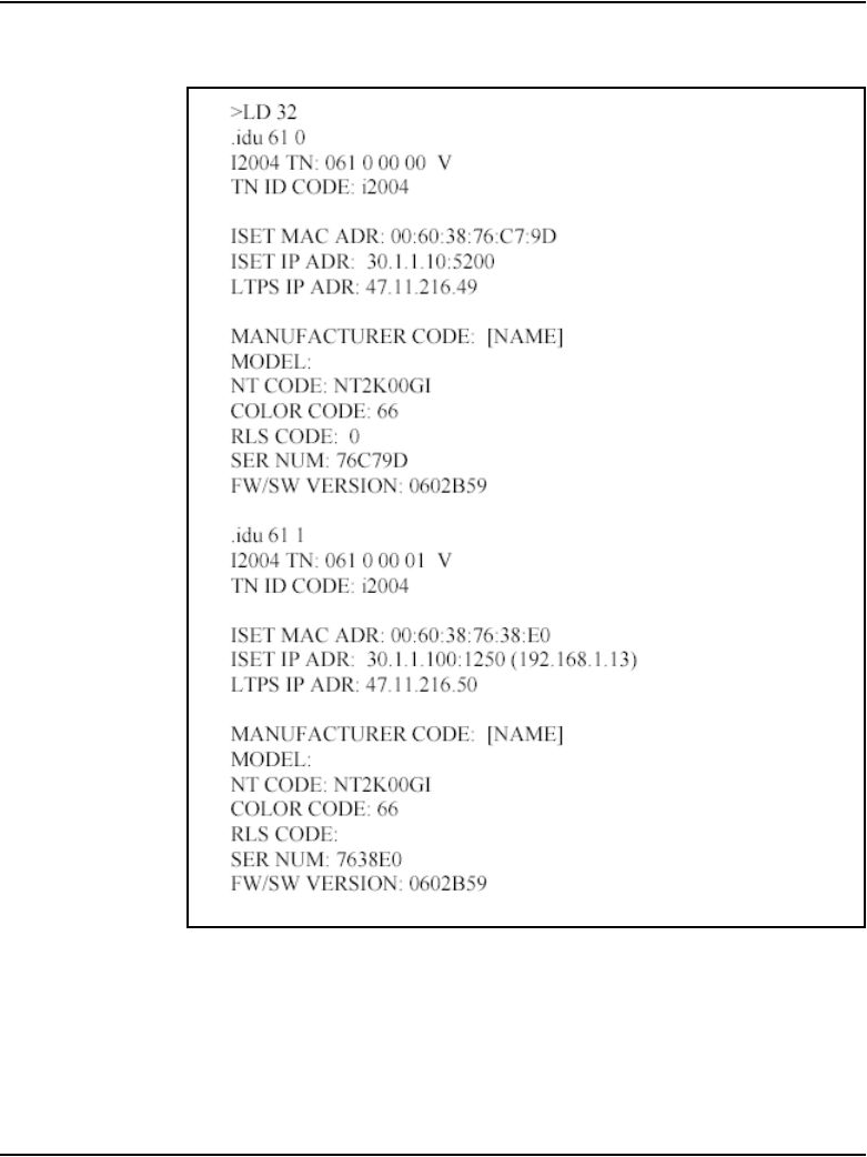
Voice Gateway Media Card maintenance Page 709 of 910
IP Line Description, Installation and Maintenance
Figure 233
IDU command output
Any information about attached IP Phone KEMs is also displayed.

Page 710 of 910 Voice Gateway Media Card maintenance
553-3001-365 Standard 4.00 August 2005
In the example in Figure 233 on page 709, the first IP Phone is not behind a
NAT device; the second IP Phone is behind a NAT device. The ISET IP
ADR field displays the IP Phone’s signaling IP address as seen by the LTPS.
If the IP Phone is behind a NAT device, the ISET IP ADR field displays the
public address (the address seen by the LTPS) followed by the private IP
address (the address configured at the IP Phone) in parenthesis.
This format applies only for IP Phone Virtual TNs.
If the IP Phone is not registered with the Call Server, an NPR0048 message
is generated. If the IP Phone is registered but idle, the system prints the
IP Phone’s IP address and Voice Gateway Media Card’s IP address and
generates an NPR0053 message. As well, if the IP Phone is registered, but the
Call Server is not responding, an NPR0503 message is generated.
IP Line CLI commands
IP Line CLI commands are designed to supplement Overlay commands and
to introduce features specific to the ITG-P 24-port card, Media Cards, and
Signaling Server platform.
All the CLI commands listed in Table 87 to Table 106 are supported on the
ITG-P 24-port card and Media Cards. The CLI commands are also available
on the Signaling Server if an “X” is shown in the Signaling Server column of
the table.
The IP Line CLI commands are accessed by connecting a TTY to the MAINT
port on the Voice Gateway Media Card faceplate. Alternatively, use Telnet to
access the CLI. These IP Line CLI commands are entered at the IPL> prompt.
Instructions for connecting to the maintenance port of the Signaling Server
are described in Communication Server 1000S: Installation and
Configuration (553-3031-210). Refer to the “Signaling Server maintenance
ports” section.
The commands are grouped into the following categories:
• “General purpose commands” on page 711
• “File Transfer commands” on page 715
• “IP Configuration commands” on page 719

Voice Gateway Media Card maintenance Page 711 of 910
IP Line Description, Installation and Maintenance
• “Reset commands” on page 720
• “DSP commands” on page 721
• “Upgrade commands” on page 721
• “IPL> shell command” on page 722
• “IP Phone Installer Password commands” on page 723
• “Voice Gateway commands” on page 726
• “Data Path Capture Tool commands” on page 727
• “Translation IP/DN commands” on page 728
• “Graceful Disable commands” on page 739
• “IP Phone Loss Plan commands” on page 740
• “Patching Tool commands” on page 747
• “General trace tool commands” on page 748
• “Protocol trace tool CLI commands for the NCS” on page 750
• “Maintenance audit commands” on page 756
• “Audit commands” on page 757
General purpose commands
Table 87 lists the general purpose IPL> commands.
Table 87
General purpose commands (Part 1 of 4)
IPL> Command Description
Signaling
Server
iDisplays the current task list. X
itgHelp Displays the complete command list.
? also shows the command list.
logout Exits the IPL> Command Line Interface.
routeAdd Adds a route to the network routing table. X

Page 712 of 910 Voice Gateway Media Card maintenance
553-3001-365 Standard 4.00 August 2005
routeShow Displays the current host and network routing
tables.
X
logPrintOff Turns off logging in the TTY session currently
logged in.
logPrintOn Turns on logging in the TTY session currently
logged in.
chkdsk chkdsk “/C:”
Checks the internal file system for errors.
chkdsk “/C:”, 1
Repairs the file system errors and saves the
damaged cluster in files.
chkdsk “/C:”, 2
Repairs file system errors and returns damaged
clusters to the free pool.
ping “host”,
“numpackets”
Sends an ICMP ECHO_REQUEST packet to a
network host. The host matching the destination
address in the packets responds to the request. If a
response is not returned, the sender times out. This
command is useful to determine if other hosts or
Voice Gateway Media Cards are communicating
with the sender card. The “numpackets” parameter
specifies how many packets to send. If it is not
included, ping runs until it is stopped by Ctrl-C (also
exits the IPL> CLI).
Example:
IPL> ping “47.82.33.123”, 10
X
Table 87
General purpose commands (Part 2 of 4)
IPL> Command Description
Signaling
Server

Voice Gateway Media Card maintenance Page 713 of 910
IP Line Description, Installation and Maintenance
electShow Displays a list of cards in the node and information
about each card. This includes showing all
registered followers to a leader.
The output has two sections:
• cards currently registered
• cards that are in the BOOTP.TAB configuration
but not yet registered.
X
itgCardShow Displays Voice Gateway Media Card information. X
itgMemShow Displays memory usage. X
ifShow Displays detailed IP address information, including
MAC addresses.
X
IPInfoShow Displays IP address information. X
serialNumShow Displays card serial number.
This command displays the same Voice Gateway
Media Card serial number that is displayed in the
LD 32 IDC command.
firmwareVersionShow Displays firmware version number. X
numChannelsShow Displays number of available channels.
swVersionShow Displays software version. X
logFileOn Turns on error logging to the syslog file.
logFileOff Turns off error logging to the syslog file.
logShow Displays information about the current logging
configuration. Indicates whether logging is on or off.
logConsoleOn Turns on error logging to the console.
Table 87
General purpose commands (Part 3 of 4)
IPL> Command Description
Signaling
Server

Page 714 of 910 Voice Gateway Media Card maintenance
553-3001-365 Standard 4.00 August 2005
logConsoleOff Turns off error logging to the console.
isetShow Displays general information for all registered IP
Phones. For example, the command displays the IP
address of the IP Phone, the VTN that the IP Phone
is associated with, indicates the type of IP Phone
such as IP Phone 2001, IP Phone 2002, and
IP Phone 2004, or IP Softphone 2050, and provides
the type of registration and the new registration
status.
X
isetShowByTN Displays general information about all registered IP
Phones, sorted by TN.
X
isetShowByIP Displays general information about all registered IP
Phones, sorted by IP address.
X
pbxLinkShow Displays information about the link to the CPU,
including the configuration and link status.
X
itgAlarmTest Generates ITGxxxx test alarms. X
itsAlarmTest Generates ITSxxxx test alarms.
itgPLThreshold Sets the IP Phone and gateway alarm packet loss
threshold (units 0.1%). An alarm is generated when
the threshold is reached.
elmShow Displays a list of supported languages. X
itgChanStateShow Displays the state for channels; for example, if they
are idle or busy.
Table 87
General purpose commands (Part 4 of 4)
IPL> Command Description
Signaling
Server

Voice Gateway Media Card maintenance Page 715 of 910
IP Line Description, Installation and Maintenance
File transfer commands
Table 88 lists the file transfer commands.
Table 88
File Transfer commands (Part 1 of 4)
IPL> Commands Description
Signaling
Server
swDownload
“hostname”,
“username”,
“password”,
“directory path”,
“filename”
Loads a new version of software from the FTP host to the
Voice Gateway Media Card.
Updates the software on the Voice Gateway Media Card
with the binary file received from an FTP server
corresponding to the hostname IP address. The Voice
Gateway Media Card FTP client performs a Get which
downloads the file to the flash bank. A checksum is
calculated to verify correct delivery. Once the new software
version is successfully downloaded, the Voice Gateway
Media Card must be rebooted with cardReset to run the
new software.
Note: Hostname refers to the either IP address of the FTP
host, or the Voice Gateway Media Card itself or another
Voice Gateway Media Card when a PC Card in the /A:
drive of the Voice Gateway Media Card contains the
software binary file.
Example:
IPL> swDownload “47.82.32.346”, “anonymous”, “guest”,
“/software”, “VxWorks.mms”
X

Page 716 of 910 Voice Gateway Media Card maintenance
553-3001-365 Standard 4.00 August 2005
configFileGet
“hostname”,
“username”,
“password”,
“directory path”,
“filename”
Sends an updated CONFIG.INI file from OTM to the Voice
Gateway Media Card.
Updates the CONFIG.INI file on the Voice Gateway Media
Card with the CONFIG.INI file on the specified host,
account, and path. The configFileGet task on the ITG host
initiates an FTP session with the given parameters and
downloads the file to flash file system. The CONFIG.INI file
also contains the gatekeeper IP address, gateway
password, and gateway DN-port mapping table.
Example:
IPL> configFileGet “ngals042”, “anonymous”, “guest”,
“/configDir”, “config.ini”
X
bootPFileGet
“hostname”,
“username”,
“password”,
“directory path”,
“filename”
Updates the BOOTPtab file on the Voice Gateway Media
Card with the BOOTPtab file on the specified host, account
and path. The bootpFileGet task on the ITG host initiates
an FTP session with the given parameters and downloads
the file to flash file system.
Example:
IPL> bootPFileGet “ngals042”, “anonymous”, “guest”,
“/bootpDir”, “bootptab”
X
Table 88
File Transfer commands (Part 2 of 4)
IPL> Commands Description
Signaling
Server

Voice Gateway Media Card maintenance Page 717 of 910
IP Line Description, Installation and Maintenance
hostFileGet
“hostname”,
“username”,
“password”,
“directory path”,
“filename”,
“ITGFileName”,
listener
Transfers any file from OTM to the Voice Gateway Media
Card. This command gets any file from the host and does a
Get using FTP to the Voice Gateway Media Card.
Note: ITGFileName is the full path AND filename of where
the file is to be placed. The listener parameter indicates
which module to inform of the successful file transfer. It
can be set to –1 to be disabled.
Example:
IPL> hostFileGet “ngals042”, “anonymous”, “guest”,
“/hostfileDir”, “hostFile.txt”,
“/C:ITGFILRDIR/ITGFILE.TXT”, -1
X
currOMFilePut
“hostname”,
“username”,
“password”,
“directory path”,
“filename”
Sends the current Operational Measurements (OM) file to
the specified host.
The OMFilePut task on the ITG host initiates an FTP
session with the given parameters and downloads the
Voice Gateway Media Card’s Operational Measurements
file to the specified location on the host.
Example:
IPL> currOMFilePut “ngals042”, “anonymous”, “guest”,
“/currDir”, “omFile”
X
prevOMFilePut
“hostname”,
“username”,
“password”,
“directory path”,
“filename”
Sends the previous Operational Measurements (OM) file to
the specified host.
The OMFilePut task on the ITG host initiates an FTP
session with the given parameters and downloads the
Voice Gateway Media Card’s Operational Measurements
file to the specified location on the host.
Example:
IPL> prevOMFilePut “ngals042”, “anonymous”, “guest”,
“/prevDir”, “omFile”
X
Table 88
File Transfer commands (Part 3 of 4)
IPL> Commands Description
Signaling
Server

Page 718 of 910 Voice Gateway Media Card maintenance
553-3001-365 Standard 4.00 August 2005
LogFilePut
“hostname”,
“username”,
“password”,
“directory path”,
“filename”
Sends the syslog file from the Voice Gateway Media Card
to OTM.
The LogFilePut task on the ITG host initiates an FTP
session with the given parameters and downloads the
Voice Gateway Media Card’s log file to the specified
location on the host.
Example:
IPL> LogFilePut “ngals042”, “anonymous”, “guest”,
“/currDir”, “logFile”
bootPFilePut
“hostname”,
“username”,
“password”,
“directory path”,
“filename”
Sends the BOOTPtab file from the Voice Gateway Media
Card to OTM.
Example:
IPL> bootPFilePut “ngals042”, “anonymous”, “guest”,
“/bootpDir”, “bootpFile”
X
hostFilePut
“hostname”,
“username”,
“password”,
“directory path”,
“filename”,
ITGFileName
Transfers any file from the Voice Gateway Media Card to
the OTM PC.
Example:
IPL> hostFilePut “ngals042”, “anonymous”, “guest”,
“/hostDir”, “hostFile”, “/C:/CONFIG/CONFIG1.INI”
X
omFilePut
“hostname”,
“username”,
“password”,
“directory path”,
“filename”,
ITGFileName
Sends the current Operational Measurements (OM) file to
the specified host.
Example:
IPL> OMFilePut “ngals042”, “anonymous”, “guest”,
“/hostDir”, “omFile”
X
Table 88
File Transfer commands (Part 4 of 4)
IPL> Commands Description
Signaling
Server

Voice Gateway Media Card maintenance Page 719 of 910
IP Line Description, Installation and Maintenance
IP configuration commands
Table 89 lists the IP configuration IPL> commands.
Table 89
IP Configuration commands
IPL> Command Description Signaling
Server
NVRIPSet Configures the IP address in NVRAM.
NVRGWSet Configures the default gateway address in NVRAM.
NVRSMSet Configures the subnet mask in NVRAM.
NVRIPShow Prints the values of the IP parameters that reside in
NVRAM.
NVRClear Clear IP parameters in NVRAM.
nvramLeaderSet Configures the Leader bit in NVRAM.
nvramLeaderClr Clears the Leader bit in NVRAM, but does not erase
the IP parameters in NVRAM.
setLeader Configures a Leader card, including the IP address,
gateway, subnet mask, boot method to static, and
Leader bit in NVRAM. This one command does all the
necessary actions to make a Leader.
clearLeader Clears the Leader information in NVRAM, sets the boot
method to use BOOTP, and removes the old
configuration files. This command makes a Leader
card into a Follower card.
tLanDuplexSet Configures the TLAN Ethernet duplex mode.
tLanSpeedSet Configures the TLAN Ethernet speed.

Page 720 of 910 Voice Gateway Media Card maintenance
553-3001-365 Standard 4.00 August 2005
Reset commands
Table 90 lists the Reset IPL> commands.
Table 90
Reset commands
IPL> Command Description Signaling
Server
cardReset Resets a Voice Gateway Media Card. This command
performs a warm reboot of the Voice Gateway Media
Card. The card must be in the OOS state to use this
command.
isetReset “tn” l s c u
isetReset “tn” c u
Resets the IP Phone on Option 51C/61C/81/81C.
Resets the IP Phone on Small Systems and CS 1000
systems.
X
isetResetAll Resets all registered IP Phones. X
resetOM Resets the operational measurement file timer. This
command resets all operational measurement
parameters collected since last log dump.
X
lastResetReason Displays the reason for the last card reset.

Voice Gateway Media Card maintenance Page 721 of 910
IP Line Description, Installation and Maintenance
DSP commands
Table 91 lists the DSP IPL> commands applicable to the Voice Gateway
Media Card.
Upgrade commands
Table 92 lists the upgrade IPL> commands.
Table 91
DSP commands
IPL> Command Description Signaling
Server
DSPReset Resets the specified DSP.
DSPNumShow Displays the number of DSPs on the Voice Gateway
Media Card.
Table 92
Upgrade commands
IPL> Command Description Signaling
Server
umsPolicyShow Displays the current upgrade policy. X
umsUpgradeAll Upgrades all registered IP Phones according to
policy and firmware file.
X
umsUpgradeTimerShow Shows the upgrade schedule. X
umsUpgradeTimerCancel Cancels the scheduled upgrade. X

Page 722 of 910 Voice Gateway Media Card maintenance
553-3001-365 Standard 4.00 August 2005
IPL> shell commands
Table 93 lists the command to change the IPL> shell password.
Table 93
IPL> shell command
IPL> command Description Signaling
Server
shellPasswordSet Changes the current user name and password of
the IPL> CLI shell.

Voice Gateway Media Card maintenance Page 723 of 910
IP Line Description, Installation and Maintenance
IP Phone Installer Password commands
Table 94 lists the IP Phone Installer Password commands.
Table 94
IP Phone Installer Password commands (Part 1 of 3)
IPL> command Description
Signaling
Server
nodePwdSet “password” Sets and enables the administrative IP Phone
Installer (node) Password. This is also known as
the node level IP Phone Installer Password.
If a null password (0 characters in length) is
configured, all IP Phones that attempt to register
after this command has been issued display a
prompt for node password before the TN can be
modified.
The “password” parameter must be null or 6 to
14 digits in length; The valid characters are 0 – 9
* #.
The null password causes the Node ID and
Password screen on the IP Phone to be skipped
during restart. This command can be entered at
any time; the new password entered overwrites
the prior password.
X
nodePwdShow Displays the settings of the IP Phone Installer
Password. The command displays the current
password, the state of password entry
(enable/disable), the temporary password, and
the number of uses and time to expiry.
X
nodePwdEnable Enables the administrative IP Phone Installer
Password setting. After this command is
entered, all IP Phones registering display the
password screen.
X

Page 724 of 910 Voice Gateway Media Card maintenance
553-3001-365 Standard 4.00 August 2005
nodePwdDisable Disables both the administrative and the
temporary IP Phone Installer Password settings.
After this command is entered, all IP Phones
display the original Node ID and TN screen
during registration.
X
Table 94
IP Phone Installer Password commands (Part 2 of 3)
IPL> command Description
Signaling
Server

Voice Gateway Media Card maintenance Page 725 of 910
IP Line Description, Installation and Maintenance
nodeTempPwdSet
“tempPwd”, uses, <time>
Configures the temporary IP Phone Installer
Password. This password is disabled by default.
The password must be a string 6 to 14 digits in
length. A null password cannot be entered. The
valid tempPwd characters are 0 – 9 * #.
The uses parameter is a numeric value from
0-1000. This parameter specifies the number of
uses for which the temporary password is valid.
The range for the time parameter is 0 –
240 hours, which is a maximum of 10 days. The
time parameter specifies the duration in hours
that the password is valid.
• If the uses parameter is set to zero, the time
parameter is mandatory. As a result, the
password only expires based on time.
• If the uses parameter is non-zero, the time
parameter is optional.
• If both the uses and time parameters are
entered, the password expires on whichever
comes first, that is, uses is reduced to zero or
the time has expired.
• If both uses and time are entered and both
are set to zero, it is the same as not setting
the temporary password at all.
This command can be entered at any time and
the new parameters overwrite the existing
temporary password’s parameters.
X
nodeTempPwdClear Deletes the temporary IP Phone Installer
Password. It also reset the uses and time
parameters to zero.
X
Table 94
IP Phone Installer Password commands (Part 3 of 3)
IPL> command Description
Signaling
Server

Page 726 of 910 Voice Gateway Media Card maintenance
553-3001-365 Standard 4.00 August 2005
Voice Gateway commands
Table 95 lists the Voice Gateway commands used on the Voice Gateway
Media Card.
vgwShow
The vgwShow command can be issued with no parameters or with the IP
address of an IP Phone using one of the Voice Channels.
vgwShow “x.x.x.x”
where “x.x.x.x” is the IP address of one of the IP Phones.
The IP address “x.x.x.x” is the PUBLIC IP address of the IP Phone. If there
are multiple IP Phones using the same public IP address, the output will be
similar to the example shown in Figure 234 on page 727.
Table 95
Voice Gateway commands
IPL> command Description
Signaling
Server
vgwPLLog Toggles gateway packet loss logging on and off.
vgwShow Displays information about the active (non-idle and
equipped) gateway channels.
Entering this command with the IP address of an IP
Phone at the Command Line Interface of any node’s
Voice Gateway Media Card displays the identification
of the card that has a gateway channel in use by the IP
Phone. This information is useful when there is a need
to identify from which card to collect gateway statistics
(for example, packet loss).
vgwShowALL Displays information about all gateway channels.
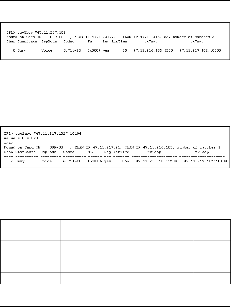
Voice Gateway Media Card maintenance Page 727 of 910
IP Line Description, Installation and Maintenance
Figure 234
vgwShow command sample output
The number of IP Phones that use that public IP address is printed (2 in this
example), but only one of the IP Phones is displayed. To see the other
IP Phone, determine the Public IP address and Public Media Port using the
command isetNATShow. Then enter vgwShow using the Public IP address
and Public Media Port. An example of the output is shown in Figure 235.
Figure 235
vgwShow sample with Public information
Data Path Capture Tool commands
Table 96 lists the commands used with the Data Path Capture Tool.
Table 96
Data Path Capture Tool commands (Part 1 of 2)
IPL> command Description
Signaling
Server
captureStart Begins the capture operation. When the command is
entered, data for the gateway channel <tcid> (0-23 for
ITG-P 24-port card and 0-31 for Media Card) begins
to be captured to the circular queue.
captureStop Stops the audio data capture.

Page 728 of 910 Voice Gateway Media Card maintenance
553-3001-365 Standard 4.00 August 2005
Translation IP/DN commands
Table 97 lists the LD 117 commands to translate an IP Phone’s DN to its IP
address and its IP address to its DN.
Search criteria
If a customer number is entered, only that customer is searched for the
designated DN. If no customer number is entered, the database for all
customers on the system is searched.
captureSaveLocal Dumps the contents of the circular queue to the
specified file on the memory PC Card inserted in the
/A: drive on the Voice Gateway Media Card’s
faceplate.
captureSaveRemote FTPs the contents of the circular queue to the
specified file on the remote server.
captureFree Frees the capture queue.
Table 97
Translation IP/DN commands
IPL> command Description
Signaling
Server
PRT DNIP
<DN>
[<CustomerNo>]
Prints a list of IP addresses for every IP Phone
registered with the specified DN.
PRT IPDN
<IPAddress>
Prints a list of DNs configured for the specified
IP address(es).
Table 96
Data Path Capture Tool commands (Part 2 of 2)
IPL> command Description
Signaling
Server

Voice Gateway Media Card maintenance Page 729 of 910
IP Line Description, Installation and Maintenance
The PRT DNIP command accepts a partially defined DN; that is, a DN
entered with only partial leading digits. For example, entering a DN of 34
with no customer number results in output for any DN in the system starting
with 34.
PRT DNIP output
The PRT DNIP command generally produces the following output:
• an initial line displaying the DN and customer number. If there is output
for multiple customers, this line is repeated before each customer’s
output.
• information for each occurrence of the DN on any IP Phone for that
customer.
—TN
— set type
— key number of DN appearance and type of DN
— current IP address of the IP Phone
— configured zone for the IP Phone
— state of the IP Phone’s registration
If the IP Phone is behind a NAT device, the public IP address is displayed,
with the private IP address underneath in parenthesis.
An example of PRT DNIP output is shown in Figure 236 on page 730.
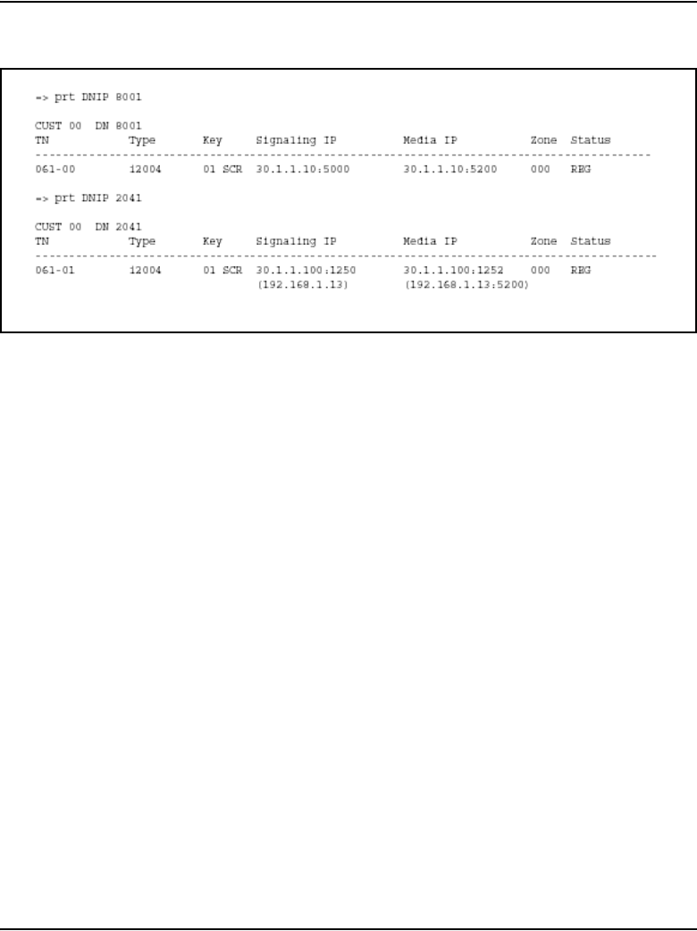
Page 730 of 910 Voice Gateway Media Card maintenance
553-3001-365 Standard 4.00 August 2005
Figure 236
PRT DNIP output
PRT IPDN
The PRT IPDN command produces the following output:
• an initial line displaying the IP address for the search
• a second line displaying the customer number, TN, set type, zone and
registration status of the IP Phone using the specified IP address
• information for all DNs configured on that IP Phone
— key number of DN appearance and type of DN
—DN
— configured CPDN for the DN
If the IP Phone is behind a NAT device, the public IP address is displayed,
followed by the private IP address in parenthesis.
An example of PRT IPDN output is shown in Figure 237 on page 731.
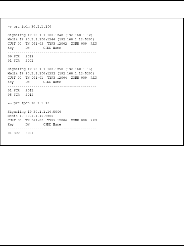
Voice Gateway Media Card maintenance Page 731 of 910
IP Line Description, Installation and Maintenance
Figure 237
PRT IPDN output
Partial IP addresses
Partial IP addresses can be entered. Partial IP addresses can be entered with
only the leading digits of the IP address (for example, 142.10), or as the IP
address with zeroes at the end (for example, 142.10.0.0).
The following examples for “PRT IPDN <IP_ADDR>” shows a partial IP
address of 47.0.0. The zeroes in the <IP_ADDR> are handled as if they are
trimmed off. This means that the output of PRT IPDN 47 is the same as that
of PRT IPDN 47.0.0.

Page 732 of 910 Voice Gateway Media Card maintenance
553-3001-365 Standard 4.00 August 2005
A sample of IP Phones has been configured in the following manner:
IP Address TN DN
47.11.216.138 063-20 4120
47.11.216.140 061-02 4002
47.11.215.39 061-00 4000
47.11.215.38 063-00 4100
47.11.215.41 063-01 4101

Voice Gateway Media Card maintenance Page 733 of 910
IP Line Description, Installation and Maintenance
Example 1
To print the information on the IP Phones whose IP address starts with
47.11.215, enter the following:
=> prt ipdn 47.11.215
The following output is printed:
IP 47.11.215.38
CUST 01 TN 063-00 TYPE i2004 ZONE 001 REG
Key DN CPND Name
---------------------------------------------
00 SCR 4100 I2004_Cust_1 VLN63_00
IP 47.11.215.39
CUST 00 TN 061-00 TYPE i2004 ZONE 000 REG
Key DN CPND Name
---------------------------------------------
00 SCR 4000 I2004_Cust_0 VLN61_00
IP 47.11.215.41
CUST 01 TN 063-01 TYPE i2001 ZONE 001 REG
Key DN CPND Name
---------------------------------------------
00 SCR 4101 I2001_Cust_1 VLN63_01

Page 734 of 910 Voice Gateway Media Card maintenance
553-3001-365 Standard 4.00 August 2005
Example 2
Alternatively, to print the information on the IP Phones whose IP address
starts with 47.11.215, enter the following:
=> prt ipdn 47.11.215.0
The following output is printed:
IP 47.11.215.38
CUST 01 TN 063-00 TYPE i2004 ZONE 001 REG
Key DN CPND Name
---------------------------------------------
00 SCR 4100 I2004_Cust_1 VLN63_00
IP 47.11.215.39
CUST 00 TN 061-00 TYPE i2004 ZONE 000 REG
Key DN CPND Name
---------------------------------------------
00 SCR 4000 I2004_Cust_0 VLN61_00
IP 47.11.215.41
CUST 01 TN 063-01 TYPE i2001 ZONE 001 REG
Key DN CPND Name
---------------------------------------------
00 SCR 4101 I2001_Cust_1 VLN63_01

Voice Gateway Media Card maintenance Page 735 of 910
IP Line Description, Installation and Maintenance
Example 3
To print the information on the IP Phones whose IP address starts with
47.11.216, enter the following:
=> prt ipdn 47.11.216
The following output is printed:
IP 47.11.216.138
CUST 01 TN 063-20 TYPE i2002 ZONE 001 REG
Key DN CPND Name
---------------------------------------------
00 SCR 4120 I2002_Cust_1 VLN63_20
IP 47.11.216.140
CUST 00 TN 061-02 TYPE i2002 ZONE 000 REG
Key DN CPND Name
---------------------------------------------
00 SCR 4002 I2002_Cust_0 VLN61_02

Page 736 of 910 Voice Gateway Media Card maintenance
553-3001-365 Standard 4.00 August 2005
Example 4
Alternatively, to print the information on the IP Phones whose IP address
starts with 47.11.216, enter the following:
=> prt ipdn 47.11.216.0
The following output is printed:
IP 47.11.216.138
CUST 01 TN 063-20 TYPE i2002 ZONE 001 REG
Key DN CPND Name
---------------------------------------------
00 SCR 4120 I2002_Cust_1 VLN63_20
IP 47.11.216.140
CUST 00 TN 061-02 TYPE i2002 ZONE 000 REG
Key DN CPND Name
---------------------------------------------
00 SCR 4002 I2002_Cust_0 VLN61_02
Graceful TPS commands
Table 98 on page 737 and Table 99 on page 739 lists the commands used to
gracefully disable the LTPS and Voice Gateway services and the commands
to enable these services after they have been disabled.

Voice Gateway Media Card maintenance Page 737 of 910
IP Line Description, Installation and Maintenance
The following Graceful TPS CLI commands are available at the IP Line shell.
Table 98
Graceful TPS commands (Part 1 of 2)
Command Description
disiTPS Disables the LTPS service only.
No new IP Phones are registered on the card and all registered IP
Phones are reset when they become idle.
This command applies to both the Voice Gateway Media Card and
Signaling Server. On the Signaling Server, this command affects
only the LTPS. It does not affect the virtual trunks or gatekeeper
components, which means the node mastership is not moved to
another LTPS.
disiVGW Disables the Voice Gateway only.
All Voice Gateways unregister with the Call Server when they
become idle. This command is applicable only to the Voice Gateway
Media Card or the stand-alone IP Line application.
disiAll Disables both the LTPS service and the Voice Gateway channels.
This command is a combination of both disiTPS and disiVGW
commands.
On the Signaling Server, this command affects only the LTPS. It
does not affect the virtual trunks or gatekeeper components, which
means the node mastership is not moved to another LTPS.
enaTPS Enables the LTPS service.
This command is used after the disTPS command to bring the LTPS
back into service.
This command applies to both Voice Gateway Media Cards and the
Signaling Server. On the Signaling Server, this command affects the
LTPS only. It does not affect the virtual trunks or gatekeeper
components.

Page 738 of 910 Voice Gateway Media Card maintenance
553-3001-365 Standard 4.00 August 2005
enaVGW Enables the Voice Gateway.
All gateway channels register with the Call Server. This command is
applicable only to the Voice Gateway Media Card or the stand-alone
IP Line application.
enaAll Enables both the LTPS service and the Voice Gateway channels.
This command is a combination of both enaTPS and enaVGW
commands.
On the Signaling Server, this command affects only the LTPS. It
does not affect the virtual trunks or gatekeeper components.
disableServices Causes the Voice Gateway Media Card or Signaling Server to
gracefully switch the registered resources to the other Voice
Gateway Media Cards or Signaling Servers located in the same
node. This command does not interrupt established calls.
forceDisableServices Forces all registered resources on the Voice Gateway Media Card
or Signaling Server to reregister with the other Voice Gateway
Media Cards or Signaling Servers in the node. This command
interrupts established calls.
enableServices Enables all the Voice Gateway Media Cards or Signaling Servers to
accept registrations of resources.
levelRegistations Causes the Voice Gateway Media Card or Signaling Server to
attempt to balance the registration load between this card/server
and the rest of the node components.
Table 98
Graceful TPS commands (Part 2 of 2)
Command Description

Voice Gateway Media Card maintenance Page 739 of 910
IP Line Description, Installation and Maintenance
Table 99
Graceful Disable commands (Part 1 of 2)
IPL> command Description
Signaling
Server
disServices Causes the Voice Gateway Media Card or Signaling
Server to gracefully switch the registered resources to
the other Voice Gateway Media Cards or Signaling
Servers located in the same node. This command does
not interrupt established calls
X
disiAll Gracefully disables both the LTPS and voice gateway
service on the Voice Gateway Media Card.
Gracefully disables the LTPS on the Signaling Server.
X
disiTPS Gracefully disables the LTPS service on the Voice
Gateway Media Card. Prevents new IP Phones
registering on the card, and all registered IP Phones
are redirected to another card when idle.
X
disiVGW Gracefully disables voice gateway service.
enaAll Enables both the LTPS and voice gateway service on
the Voice Gateway Media Card.
Enables the LTPS on the Signaling Server.
X
enlServices Enables all the Voice Gateway Media Cards or
Signaling Servers to accept registrations of resources
X
enaTPS Enables the LTPS service. X
enaVGW Enables the voice gateway service.
forcedisServices Forces all registered resources on the Voice Gateway
Media Card or Signaling Server to reregister with the
other Voice Gateway Media Cards or Signaling Servers
in the node. This command will interrupt established
calls
X

Page 740 of 910 Voice Gateway Media Card maintenance
553-3001-365 Standard 4.00 August 2005
IP Phone Loss Plan (UK) commands
These commands set and adjust the gains for the UK (or other places where
loss plan adjustment of IP Phones is needed).
For more information on the UK Loss Plan, see “United Kingdom” on
page 394.
loadBalance Causes the Voice Gateway Media Card or Signaling
Server to attempt to balance the registration load
between this card/server and the rest of the node
components.
X
Table 100
IP Phone Loss Plan commands (Part 1 of 2)
IPL> command Description
Signaling
Server
UKLossPlanSet Increases the Tx level of the IP Phone to match the
requirement for the UK.
X
UKLossPlanClr Removes the loss plan adjustment and returns the IP
Phone to the default loss plan levels.
X
lossPlanPrt Prints the current IP Phone loss plan settings. X
Table 99
Graceful Disable commands (Part 2 of 2)
IPL> command Description
Signaling
Server

Voice Gateway Media Card maintenance Page 741 of 910
IP Line Description, Installation and Maintenance
Nortel recommends that the loss plan commands be entered on the node’s
Leader card while it is the node master. This process ensures that the data is
correctly propagated to all cards in the node. When installing a new Leader
card in a node with modified levels, always enter the loss plan command on
the Leader card’s CLI, even if the command was previously entered on
another card’s CLI.
Note: When a node has a modified loss plan (that is, the command
ULKLossPlanSet or lossPlanSet has been used), a new card that is
added to the node is updated with the modified loss plan 30 seconds after
the card has booted. Prior to the modified loss plan being received by the
new card, calls made by IP Phones registered to that new card have the
default loss plan levels.
lossPlanSet
<transducer>
<rlrOffset> <slrOffset>
Allows a variable offset from the default loss plan to
be entered for the specified transducer (handset,
handsfree, or headset).
The rlrOffset adjusts the level heard at the IP Phone.
The slrOffset adjusts the level transmitted from the IP
Phone.
Positive numbers reduce the level (add loss).
Negative numbers increase the level (add gain).
X
lossPlanClr Removes the loss plan adjustment and returns the IP
Phone to the default loss plan levels.
X
CAUTION
Care must be taken when altering the IP Phone’s loss
plan. Increasing the gain increases the possibility of echo
and other audio problems. Only adjust the levels when
instructed by this document or by Nortel support staff.
Table 100
IP Phone Loss Plan commands (Part 2 of 2)
IPL> command Description
Signaling
Server

Page 742 of 910 Voice Gateway Media Card maintenance
553-3001-365 Standard 4.00 August 2005
Patch and Patching Tool commands
A patch is a piece of code that is inserted or patched into an executable
program. The Patching Tool enables loadware on the Voice Gateway Media
Cards to be patched or fixed without having to upgrade the card loadware and
without service interruption. All patch commands on the Voice Gateway
Media Cards and Signaling Server are accessible at the IPL> prompt. These
commands are summarized in Table 101 on page 743 and Table 102 on
page 747.
Note: The parameter string supplied to the command must be enclosed
with double quotes. For example, the syntax for the pload command is
pload “patch1.p”
These commands are used to manage patches on the Voice Gateway Media
Card. Patches must be downloaded from a workstation to the Voice Gateway
Media Card using a modem, an FTP session, or Element Manager. Patch files
are stored in Flash memory and are loaded into DRAM memory. Once a patch
is in DRAM memory it can be activated, deactivated, and its status can be
monitored.
Perform the following tasks before loading a patch:
• Verify that the patch matches the platform’s CPU type.
• Verify the loadware version on the card.
• Block the installation if there is a mismatch.
The installation of a patch is blocked if either the CPU type or the loadware
version of the card is different than the patch. If the installation is blocked, the
reason for blocking the install is printed at the CLI. The CPU type and
loadware version are also verified during a power-up or reboot cycle. This
prevents active patches from being re-installed if the loadware version of the
card is changed.

Voice Gateway Media Card maintenance Page 743 of 910
IP Line Description, Installation and Maintenance
Table 101 lists the patch commands.
Table 101
Patch commands (Part 1 of 3)
Command Description
pload Loads a patch file from the file system in Flash memory into DRAM memory.
The loaded patch is inactive until it is put into service using the pins command.
When a patch is successfully loaded, the pload command returns a patch
handle number. The patch handle number is used as input to other patch
commands (pins, poos, pout, and plis).
Syntax:
pload “[patch-filename]”
where [patch-filename] is the filename or path of the patch file. If a filename
alone is provided, the patch must be in the /C:/u/patch directory; otherwise, the
full or relative path must be provided.
If the pload command is issued without a parameter, enter the patch filename
and other information when prompted.
pins Puts a patch that has been loaded into memory (using the pload command) into
service. This command activates a patch.
If issued successfully, the pins command indicates that global procedures,
functions, or areas of memory are affected by the patch. When prompted,
choose to proceed or not to proceed.
Syntax:
pins “[handle]”
where [handle] is the number returned by the pload command
If the pins command is issued without a parameter, enter a handle when
prompted.

Page 744 of 910 Voice Gateway Media Card maintenance
553-3001-365 Standard 4.00 August 2005
poos Deactivates a patch (takes it out-of-service) by restoring the patched procedure
to its original state.
Syntax:
poos “[handle]”
If the poos command is issued without a parameter, enter a handle when
prompted.
pout Removes a patch from DRAM memory. The patch must be taken out-of-service
(using the poos command) before it can be removed from the system.
Syntax:
pout “[handle]”
If the pout command is issued without a parameter, enter a handle when
prompted.
pstat Gives summary status information for one or all loaded patches.
For each patch, the following information is displayed: patch handle, filename,
reference number, whether the patch is in-service or out-of-service, the reason
why the patch is out-of-service (if applicable), and whether the patch is marked
for retention or not.
Note: Patch retention means that if a reset occurs, then the patch is
automatically reloaded into memory and its state (active or inactive) is restored
to what it was prior to the system going down.
Syntax:
pstat “[handle]”
If the handle is provided, only the information for the specified patch is
displayed. If the pstat is issued without a parameter, information for all the
patches is displayed.
Table 101
Patch commands (Part 2 of 3)
Command Description

Voice Gateway Media Card maintenance Page 745 of 910
IP Line Description, Installation and Maintenance
plis Gives detailed patch status information for a loaded patch.
Syntax:
plis “[handle]”
If the pout command is issued without a parameter, enter a handle when
prompted.
pnew Creates memory patches for the Voice Gateway Media Card.
• The release of the patch is assumed to be the same as that of the current
load.
• The address to be patched is checked to ensure that it is in range.
• For each address that is changed, the “old” contents are assumed to be the
current contents of that memory address.
• If a path is not provided for the new path filename then it is assumed that the
patch is in the /C:/u/patch directory.
Once a memory patch is created using the pnew command, it is loaded and
activated like any other patch.
Syntax:
pnew
Note: The pnew command has no parameter(s).
Table 101
Patch commands (Part 3 of 3)
Command Description

Page 746 of 910 Voice Gateway Media Card maintenance
553-3001-365 Standard 4.00 August 2005
Patch Directories
There are two patch directories on a Voice Gateway Media Card:
1 /C:/u/patch
This is the default directory for patch files. Patch files should be copied
to this directory.
2 /C:/u/patch/reten
Use this directory to store patch retention control files. Do not use this
directory to store patches and do not remove files from this directory.
Patch Synchronization Across a Node
Element Manager provides a mechanism for downloading and putting
patches in service across a node.
Patch synchronization across a node cannot be carried out from the IPL>
prompt.

Voice Gateway Media Card maintenance Page 747 of 910
IP Line Description, Installation and Maintenance
Table 102 lists the Patching Tool commands.
Table 102
Patching Tool commands
IPL> command Description
Signaling
Server
pins Puts a patch into service that has been loaded into
memory using the pload command.
X
plis Gives detailed patch status information for a loaded
patch.
X
pload Loads a patch file from the file system on Flash
memory into DRAM memory.
X
pnew Creates memory patches for the Voice Gateway
Media Card.
X
poos Deactivates a patch by restoring the patched
procedure to its original state.
X
pout Removes a patch from DRAM memory. X
pstat Gives summary status for one or all loaded patches. X

Page 748 of 910 Voice Gateway Media Card maintenance
553-3001-365 Standard 4.00 August 2005
General trace tool commands
Table 103 lists the general trace tool commands applicable to the Voice
Gateway Media Cards. They are issued from the LTPS prompt of the Voice
Gateway Media Cards.
IMPORTANT!
A warm boot of the system causes all tracing to cease. Traces must be
re-entered after the system has restarted.
Table 103
General trace tool commands (Part 1 of 2)
CLI Command Description
Signaling
Server
traceShow Displays the names of active traces in the system. X
traceAllOff Causes all traces that use the monitorLib server to
stop their output. This is a temporary disabling
function.
X
tracePrintOff Blocks all logging of information received by the
monitorLib service to the TTY output. This does not
include traces directed through the monitorLib
service to the RPT.LOG or SYSLOG.n services.
X
traceFileOff Causes the monitorLib server to stop logging to the
log files any and all trace information received by the
service. The log files include syslog.n for the Voice
Gateway Media Card and rpt.log for the Signaling
Server.
X
traceAllOn Clears the blocking of all trace information imposed
on the monitorLib service by the traceAllOff
command, the tracePrintOff command, and the
traceFileOff command. By default, all tracing is on.
X

Voice Gateway Media Card maintenance Page 749 of 910
IP Line Description, Installation and Maintenance
Note 1: If no directory path is supplied with the file name specified, then
the file is written to the C:/U/trace directory on the Voice Gateway Media
Cards and to the /u/trace directory on the Signaling Server.
Note 2: If no file name is given, then no trace file is generated and
output is directed to the TTY. If the file name does not meet the DOS 8.3
restriction, then the file name is rejected and no file is generated. If the
file is deleted, cannot be found, or has a write error, then the output is
directed to the TTY.
Note 3: If the output for the trace cannot be determined, then the output
is directed to the TTY.
tracePrintOn Clears only the TTY output blocking that was
imposed by the traceAllOff and tracePrintOff
commands.
X
traceFileOn Clears only the blocking of logging to files that was
imposed by the traceAllOff and traceFileOff
commands.
X
Table 103
General trace tool commands (Part 2 of 2)
CLI Command Description
Signaling
Server

Page 750 of 910 Voice Gateway Media Card maintenance
553-3001-365 Standard 4.00 August 2005
Protocol trace tool commands for the
Network Connection Service
Table 104 includes the protocol trace tool commands for the Network
Connection Service (NCS) applicable to the Voice Gateway Media Cards.
They are issued from the OAM shell.
IMPORTANT!
A warm boot of the system causes all tracing to cease. Traces must be
re-entered after the system has restarted.
Table 104
Protocol trace tool CLI commands for the NCS (Part 1 of 3)
CLI Command Description
Signaling
Server
tpsARTrace
IP <IP Address>
ID <user ID>
ALL
Allows tracing of the tpsAR protocol, which is used
to determine where an IP Phone should register.
Where:
• IP Address - a string containing the IP Phone’s
IP address
• user UID - the ID of the IP Phone to be traced
(the DN used to log in) or the H323_Alias of
where the IP Phone is trying to register
• ALL - all IP Phones are to be monitored
X
tpsARTraceOff
IP <IP Address>
ID <user ID>
ALL
Removes the specified endpoint from the list of
endpoints to be traced.
X

Voice Gateway Media Card maintenance Page 751 of 910
IP Line Description, Installation and Maintenance
tpsAROutput
<Output_Destination>
<“File Pathname”>
Sets the output for all tpsAR protocol traces.
Where:
• Output_Destination specifies where all the trace
messages for the tpsARTraceSet are to be
directed.
If the command is run from the Voice Gateway
Media Card or the vxshell prompt:
The values are:
1 = TTY
2 = RPTLOG
3 = File
4 =TTY + File
If the command is run from the OAM prompt or
PDT prompt on the Signaling Server:
The values are the actual word, not a number:
TTY
RPTLOG
FILE
TTY+FILE
• “File Pathname” is a string encapsulated in
quotes. It specifies the file to output to if option 3
or 4 was selected.
X
tpsARTraceSettings Displays the trace tool settings, which endpoints
are being traced, and where the trace output is
being directed.
X
Table 104
Protocol trace tool CLI commands for the NCS (Part 2 of 3)
CLI Command Description
Signaling
Server

Page 752 of 910 Voice Gateway Media Card maintenance
553-3001-365 Standard 4.00 August 2005
Lamp Audit and Keep Alive functions
The Lamp Audit function provides a continuous source of heartbeat messages
to ensure the IP Phone is powered and the IP connection is alive. Since there
is a reliable UDP connection from the core through to the IP Phones, any
failure of the IP Phone, the Voice Gateway Media Card, or the IP connection
is detected.
Network Signaling Diagnostics
Network Signaling Diagnostics can be run as part of the midnight routines
defined in LD 30. Fore more information, refer to Software Input/Output:
Maintenance (553-3001-511).
IP Phone Keep Alive
When the Voice Gateway Media Card detects that the IP Phone has been
disconnected, the Voice Gateway Media Card logs the event and sends an
UNREGISTER message to the system for that IP Phone.
Card or ELAN subnet failure
When the Call Server detects a loss of connection with the Voice Gateway
Media Card, the Call Server logs a message and unregisters all the IP Phones
and gateway channels associated with that Voice Gateway Media Card.
Maintenance audit
IP Line 4.5 provides a background audit that watches for tasks that go into a
suspended state. Under normal operation, a task should not go into a
suspended state. However, if it occurs, the card's processing is affected.
tpsARTraceHelp Displays a list of all CLIs used for tracing tpsAR
protocol messages, including usage and
parameters.
X
Table 104
Protocol trace tool CLI commands for the NCS (Part 3 of 3)
CLI Command Description
Signaling
Server

Voice Gateway Media Card maintenance Page 753 of 910
IP Line Description, Installation and Maintenance
If the audit task finds a suspended task, it performs the following actions:
• outputs a stack and register dump to the debug port
• outputs a file on the /C: drive
• resets the card
This function provides an automatic way to return the card to service and
provides critical debug information. The information is output to the
EXCPLOG.n files (where n is a number from 0-3) that are located in the
/C:/LOG directory. The new information is placed in these files where it
cannot be overwritten by the usual information output to the SYSLOG file
when the card reboots.
The auditRebootSet command disables the card reboot if any task is found
in a suspended state.
The maintenance audit enhancement differentiates between tasks that are
critical and non-critical.
• A critical task is any task that the IP Line application needs to function.
When a critical task is not functioning properly, it causes noticeable
degradation in the IP Line application.
• A non-critical task is any other task that does not cause noticeable
degradation to the IP Line application.
If a critical task is found suspended, the stack and register information is
dumped and the card is then reset. If a task on the critical task list disappears,
it is treated as a suspended task. Therefore, a missing critical task triggers a
reboot and a missing non-critical task does not trigger a reboot.
If a non-critical task is found suspended, the information is dumped but the
card is not reset. The card is reset when the Voice Gateway Media Card clock
reaches 2:00 a.m. (default reset time). The reset time is configured from the
CLI. This eliminates card resets that impact service for non-critical tasks by
delaying them to a non-service impacting time.

Page 754 of 910 Voice Gateway Media Card maintenance
553-3001-365 Standard 4.00 August 2005
Additional CLI commands have been added enabling any task to be marked
as critical or non-critical, regardless of its default designation. This could be
used, for example, to mark a “misbehaving” task as non-critical to avoid a
card reset. This would enable the problem to be debugged.
The maintenance audit is available only for the IP Line 4.5 application
running on the ITG-P 24-port and Media Card line cards. It is not available
on the Signaling Server as it does not have the exception handler, stack dump,
and syslog file functions of the other cards.
Critical task list
All application tasks default to the critical task list. These applications
include: TPS, VTM, SET, VTILIB, UMS, UMC, RDP, VGW, RTP, RTCP,
ELC, baseMMintTask, and A07.
The following VxWorks system tasks are also on the critical task list: tShell,
tNetTask, tExcTask, and tTelnetd.
All other tasks are on the non-critical task list. The monitor task is called
tMonTask.
Any data entered at the CLI that deviates the operation from the default is
saved in the /C:/CONFIG/AUDIT.INI text file. The contents of the file are
loaded as the application boots up and provides the required non-volatile
storage for entered settings. It is applicable only to the card on which it
resides. It can be manually copied from one card to all other cards in the node
if desired.
History file
A history file is created when the card starts. The text file is called audit.his
and it is stored in the /C:/LOG directory. This file contains a list of the
problems found and the actions taken by the maintenance audit. The audit.his
file has a fixed size of 4096 bytes.
The most recent records in the file overwrite the oldest records with newer
events appear at the beginning of the file. A record in the file is a one-line
string with maximum size of 256 characters.

Voice Gateway Media Card maintenance Page 755 of 910
IP Line Description, Installation and Maintenance
The format for the records in the history file is:
index : (timeString) TMxx taskName: DescriptionString
where:
• index – monotonically increasing record count; wraps after 9999 events
• (timeString) – the time the event was detected
• TMxx – record type: 0-reboot, 1-Suspend, and 2-TaskDisappear
• taskName – the name of problematic task
• DescriptionString – a description of the action taken
An example of the output follows.
IPL> auditHistoryShow
0001 :(APR 25 12:26:25) TM01 tCSV:Suspend
0002 :(APR 25 12:26:50) TM01 tSET:Suspend
0003 :(APR 25 12:26:50) TM00 tExcTask:Reboot
0004 :(APR 25 12:35:55) TM02 tELC:Disappear
0005 :(APR 25 12:35:55) TM00 tELC:Reboot
0006 :(APR 25 12:48:27) TM01 tUMC:Suspend
0007 :(APR 25 12:48:27) TM00 tExcTask:Reboot
0008 :(APR 25 13:15:56) TM01 tUMC:Suspend
0009 :(APR 25 13:15:56) TM00 tExcTask:Reboot
0010 :(APR 25 13:29:35) TM01 tLogTask:Suspend
0011 :(APR 25 13:45:35) TM01 tLogTask:Suspend

Page 756 of 910 Voice Gateway Media Card maintenance
553-3001-365 Standard 4.00 August 2005
Maintenance audit CLI commands
There are five CLI commands that support the maintenance audit function as
outlined in Table 105.
Table 105
Maintenance audit commands (Part 1 of 2)
Command Description
auditShow Displays the following information:
• whether a card reboot is enabled
• the time a card reboot will occur if a non-critical task
is found suspended
• a list of all tasks being monitored and their
designation (critical or non-critical)
Example:
IPL> auditShow
Reboot when detect a suspended task --- Disabled
Critical Task: tTPS tVTM tSET tVTI tUMS tUMC
tRDP tPBX tVGW tRTP tRTCP tELC baseMMintTask
tA07 tShell tNetTask tExcTask tTelnetd
Non-Critical Task: tTest
auditHistoryShow Displays the contents of the audit.his file.
auditRebootSet 0/1 Globally disables the card reboot from this audit task.
By default, this is set to 1. If it is set to 0, no card reboot
occurs when a suspended task is found for critical or
non-critical tasks.
The debug information is dumped; however, recovery
requires a manual reset of the card.

Voice Gateway Media Card maintenance Page 757 of 910
IP Line Description, Installation and Maintenance
Table 106 lists the Audit commands.
auditRebootTimeSet “timeString” Sets the reset time for non-critical tasks to the value
defined by the timeString parameter.
The timeString is formatted as HH:MM and is in 24-hour
clock format. By default, the time is set to 02:00 (2 AM).
auditTaskSet tTaskName, 0/1 Forces a task to be considered critical or non-critical.
This command overrides the audit’s default setting for
the task. The tTaskName parameter specifies the task
(the VxWorks taskname), as displayed by the “i”
command.
The value of 0 marks the task as non-critical, the value
of 1 marks it as critical.
Table 106
Audit commands
Command Description
Signaling
Server
auditHistoryShow Displays the recent history of the audit task’s activity.
auditRebootSet Distributes globally the audit task from resetting the
card.
auditRebootTimeSet Sets the time of non-critical task triggered card
resets.
auditShow Displays audit task information, such as a list of tasks
and the time for non-critical tasks triggered resets.
auditTaskSet Enables manual setting of a task to critical or
non-critical status.
Table 105
Maintenance audit commands (Part 2 of 2)
Command Description

Page 758 of 910 Voice Gateway Media Card maintenance
553-3001-365 Standard 4.00 August 2005
Voice Gateway Media Card self-tests
During power-up, the Voice Gateway Media Card performs diagnostic tests
to ensure correct operation. The faceplate RS-232 port on the Voice Gateway
Media Card can be used to monitor the progress of these tests. When the
processor responds correctly, the controller switches its serial port to provide
Card LAN communication and connects the processor with the external
RS-232 port.
Troubleshoot a software load failure
Symptoms
OTM cannot establish connection with the Voice Gateway Media Card. The
faceplate LCD display reads “BIOS.”
Problem
The Voice Gateway Media Card has booted the BIOS load.
Diagnosis
In the event of a failure to load and run the IP Line 4.5 software, the Voice
Gateway Media Card defaults to the BIOS load. This load consists of a
prompt that enables commands to reload the IP Line loadware and reboot.
There are three known reasons for the failure to load the IP Line software:
• Not enough memory due to a faulty or missing SIMM.
• Corruption of the IP Line loadware image in flash memory.
• The escape sequence to boot from the BIOS has been inadvertently sent
down the serial line due to noise.
To determine the cause of the IP Line load failure, reboot and monitor the
booting sequence through the serial port. Capture the booting sequence to aid
in communication with technical support personnel.

Voice Gateway Media Card maintenance Page 759 of 910
IP Line Description, Installation and Maintenance
Examples of booting sequences
Case 1
The following excerpt from the booting sequence indicates the amount of
memory onboard.
Memory Configuration
Onboard: 4MB
SIMM: 16MB
Total: 20MB
In the absence or failure of the SIMM, the total memory is 4MB; that is not
enough memory to support the IP Line application.
Case 2
The following excerpt from the booting sequence indicates the Voice
Gateway Media Card locating and loading the IP Line loadware from flash
memory:
Cookie array value: 0x111111100
Checksum Validation at Bank Address: 0xF9800000
Checksum in ROM = 35582602
Length of bank = 0004FEF8
Calculated Checksum = 35582602
Checksum array value: 0x11111100
Loading code from address: F9800010
Verifying ROM to RAM copy...
ROM to RAM copy completed OK
Jumping to VxWorks at 0x00E00000
EIP = 0x00E0011E
Jumping to romStart at 0x00E00300
In the event of a software load failure, the boot sequence indicates that the
BIOS is being loaded:
Cookie array value: 0x11111111
Booting from BIOS ROM

Page 760 of 910 Voice Gateway Media Card maintenance
553-3001-365 Standard 4.00 August 2005
Case 3
The boot sequence indicates that the “xxx” sequence has been entered and the
BIOS is being loaded.
Solutions
Case 1
If a SIMM is missing, install a 16MB SIMM into the SIMM slot which is
underneath the daughterboard. If the SIMM is present, check that the SIMM
is properly seated. Otherwise, the SIMM is faulty and needs replacement.
Case 2
Re-attempt a software download from the OTM host. Use the following
commands:
upgradeErase
upgrade “hostname”,”hostAccount”,”hostPassword”,
“hostDirectoryPath”,”hostSWFilename”
After the software loads to flash, reboot the card:
sysReboot
If the failure to load the IP Line software into RAM persists, then the flash
device is faulty. Replace the Voice Gateway Media Card.
Case 3
The escape sequence “xxx” is rarely transmitted. Reboot the card.
Warm reboot of the Voice Gateway Media Card
The cardReset IP Line CLI command performs a warm reboot of an
out-of-service Voice Gateway Media Card:
Test the Voice Gateway Media Card DSPs
At the IPL> CLI, the following two tests can be performed on the Voice
Gateway Media Card DSPs:
• To run a self-test on the DSP daughterboard: DSPselfTest

Voice Gateway Media Card maintenance Page 761 of 910
IP Line Description, Installation and Maintenance
Note: If the DSP self-test fails, the Voice Gateway Media Card must be
replaced.
• To run a PCM loopback test, a Send loopback test, or a Receive loopback
test on the DSP daughterboard, respectively:
DSPPcmLpbkTestOn (“DSPPcmLpbkTestOff” to stop the test)
DSPSndLpbkTestOn (“DSPSndLpbkTestOff” to stop the test)
DSPRcvLpbkTestOn (“DSPRcvLpbkTestOff” to stop the test)
Note: The DSPs and all associated ports must be disabled before
performing these tests.
Work with alarm and log files
Alarm and log file output is turned on using the IPL> CLI. The following
commands can be performed at the IPL> prompt:
• To turn on or turn off the error log file, type: logFileOn or logFileOff.
• To display the modes of all log files and alarms, type: logFileShow.
Troubleshoot an IP Phone installation
If an IP Phone cannot be installed because the prompt for the node ID or TN
does not display, follow the steps in Procedure 104.
Procedure 104
Troubleshooting an IP Phone installation
1Log into one Voice Gateway Media Card in the node.
2Type the nodePwdShow command at the IPL> prompt.

Page 762 of 910 Voice Gateway Media Card maintenance
553-3001-365 Standard 4.00 August 2005
3If the administrative password is enabled (PwdEna=Yes) and there is a
null (zero-length) password (the Pwd field is blank), then the IP Phone
cannot be installed on that Voice Gateway Media Card.
4Use the nodePwdSet “password” command to set the administrative
password and to enable IP Phones to be installed. Ensure the “password”
parameter is included.
End of Procedure
Maintenance telephone
An IP Phone functions as a maintenance telephone when the CLS is defined
as MTA (Maintenance Telephone Allowed) in the Multi-line Telephone
Administration program (LD 11). A maintenance telephone enables
commands to be sent to the system; however, only a subset of the commands
that can be entered from a system terminal can be used. To access the system
using the maintenance telephone, a Special Service Prefix (SPRE) code
(defined in the Customer Data Block) is entered and followed by “91”. To
enter commands, press the keys that correspond to the letters and numbers of
the command (for example, to enter LD 42 return, key in 53#42##).
The following overlays (LDs) are accessible from an IP Phone operating as a
maintenance telephone: 30, 32, 33, 34, 36, 37, 38, 41, 42, 43, 45, 46, 60,
and 62.
Note: The above maintenance overlay operations are supported on IP
Phones except for the Tone and Digit Switch (TDS) commands of LD 34
and TONE command of LD 46.
NodeI
D
=====
=
123
PwdEn
a
=====
==
Ye s
Pwd
======
==
TmpPw
d
======
==
Uses
=====
==
Timeout
==========
0d 0h 0m 0s

Voice Gateway Media Card maintenance Page 763 of 910
IP Line Description, Installation and Maintenance
Upgrade Voice Gateway Media Card firmware
The minimum versions of IP Line 4.5 firmware for the Voice Gateway Media
Card are:
• Version 6.8 for the NTVQ01AA and NTVQ01BA Media Card hardware
platform
• Version 8.2 for the NTVQ01AB and NTVQ01BB Media Card hardware
platform
• Version 5.7 for the ITG-P 24-port card
Note: Firmware versions 6.x and 8.x can only be used for the specified
Media Card hardware platforms. They cannot be used interchangeably.
Check the Nortel web site for the most current version of the firmware. See
Appendix F on page 903.
Once the most current version of the firmware has been downloaded, follow
the steps in:
• Procedure 105 on page 763 to upgrade the firmware on the ITG-P
24-port line card
• Procedure 106 on page 766 to upgrade the firmware on the Media Card
Upgrade the ITG-P 24-port card firmware
Follow the steps in Procedure 105 on page 763 to upgrade the firmware on
the ITG-P 24-port card. Enter all the upgrade commands at the VxWorks shell
prompt. Copy the F/W binary file (on a PC Card plugged into the card’s
faceplate) to the card’s /C: drive or to a network server accessible by the card.
Procedure 105
Upgrading the ITG-P 24-port card firmware
1Check if the firmware upgrade is required. Check the firmware version by
entering the firmwareVersionShow command:
IPL> firmwareVersionShow
Firmware Version = ITG Firmware Rls 4.5
value = 40 = 0x28 = '('
IPL>

Page 764 of 910 Voice Gateway Media Card maintenance
553-3001-365 Standard 4.00 August 2005
2Depending on the location of the firmware file, enter one of the following
commands as shown in Table 107:
The firmware file name for the ITG-P 24-port line card is ITGPFW57.BIN.
The firmware file name for the NTVQ01AA/BA Media Card is
SMCFW68.BIN, The firmware file name for the NTVQ01AB/BB Media
Card is SMCFW82.BIN.
If the upgrade process is successful, the following is displayed:
Upgrade packet: 0..100..200..300..400..500..600..700..800..
tUpgradeXa: 8051XA Upgrade completed OK
tUpgradeXa: Reboot the pack to run new loadware
Note: If these messages do not display, the upgrade was not successful.
Repeat step 2 again. Do not continue with steps 4 and 5.
3Reboot the card if both of the following are true:
• the download is successful
• the software version on the card that was checked in Step 1 is
version 4.5 or later
Table 107
Upgrade command based on file location
— File is located on the card's /C: drive (The file was previously FTP’d to /C:):
upgradeXa “127.0.0.1","userid”,"password”,"</C:/path>”,"<fw_filename>”
— File is located on a PC Card plugged in the card’s faceplate:
upgradeXa “127.0.0.1”,"userid”,"password”,"</A:/path>”,"<fw_filename>”
— File is located on another card’s /C: drive (The file was previously FTPed to /C:):
upgradeXa “<ITG ELAN IPaddr>”,"userid”,"password”,"<path>”,"<fwfilename>”
— File is located on the OTM PC:
upgradeXa “<PC’s IP addr>”,"itguser”,"itguser”,"“,”<fw_filename>”
— File is located on a network FTP server:
upgradeXa "<server’s IP addr>","<uid>","<pswd>","<path>","<fw_filename>"

Voice Gateway Media Card maintenance Page 765 of 910
IP Line Description, Installation and Maintenance
However, if the software version is prior to version 4.5, enter the following
commands:
xaSend 0,0x11
W 05555,AA
W 02AAA,55
W 05555,80
W 05555,AA
W 02AAA,55
W 05555,30
Note 1: There is a space after xaSend and the letter “W”. No other
spaces are allowed. All letters are in uppercase.
Note 2: Ignore any syntax error messages that print out after the xaSend
command is entered.
After the last command is entered, the card automatically reboots.
4When the card boots up with firmware version x.x, the following messages
are printed:
ITG Firmware Rls x.x
8051XA Firmware Version x.x (Pentium) <date>
(C) Nortel Networks Inc., 1996-2004
32K External RAM detected
All FPGAs are configured
No dongle detected
8K DPRAM detected
Bank 0 Checksum - 54A9H
....
End of Procedure

Page 766 of 910 Voice Gateway Media Card maintenance
553-3001-365 Standard 4.00 August 2005
Upgrade the Media Card firmware
There are two different hardware platforms for the Media Card. Firmware
release 8.x is for the NTVQ01AB/BB Media Card platform Media card
32-port card). Firmware release 6.x is for the NTVQ01AA/BA Media Card
platform (Media Card 8-port card). The firmware releases cannot be used
interchangeably between the two types of cards. However, the upgrade
procedure remains the same for both hardware platforms.
Note: If the Media Card is NTVQ01AA Release 8 vintage or earlier,
firmware cannot be upgraded unless the 8051 OTP part is changed on the
board. NTVQ01AA cards Release 9 and later can be upgraded as
described in this section. The release label is on the faceplate below the
Hex display.
Follow the steps in Procedure 106 to upgrade the Media Card firmware.
Procedure 106
Upgrading the Media Card firmware
1Determine if the firmware upgrade is required and if the card can have its
firmware upgraded by this process.
IPL> firmwareVersionShow
Firmware Version = ITG Firmware Rls 6.5
value = 40 = 0x28 = '('
IPL>
2Check the release label on the faceplate (below the Hex display) and
ensure it is newer than NTVQ01AA Release 8.
3Reboot the card.
4While the card is booting, break into the BIOS by entering jkl when
prompted.
5At the prompt enter the following commands:
-> initMm
value = 0 = 0x0
-> spawnMm
value = 0 = 0x0
6Depending on the location of the software file, enter one of the following
commands as shown in Table 108.

Voice Gateway Media Card maintenance Page 767 of 910
IP Line Description, Installation and Maintenance
Choose the correct firmware version file for the Media Card platform..
If the upgrade process is successful, the following is displayed:
Upgrade packet:
0..100..200..300..400..500..600..700..800..900..100
0..1100..1200..
1300..1400..1500..1600..1700..1800..1900..
tUpgradeXa: 8051XA Upgrade completed OK
tUpgradeXa: Reboot the pack to run new loadware
Note: If the upgrade is not successful, these messages do not display.
Repeat step 5 again.
7Reboot the card.
Table 108
Upgrade command based on file location
— File is located on the card's /C: drive (The file was previously FTPed to /C:):
upgradeXa “127.0.0.1","userid","password","</C:/path>","<fw_filename>"
— File is located on a PC Card plugged in the card’s faceplate:
upgradeXa "127.0.0.1","userid","password","</A:/path>","<fw_filename>"
— File is located on another card’s /C: drive (The file was previously FTPed to /C:):
upgradeXa "<ITG ELAN IPaddr>","userid","password","<path>","<fw_filename>"
— File is located on the OTM PC:
upgradeXa "<PC’s IP addr>","itguser","itguser","","<Fw_filename>"
— File is located on a network FTP server:
upgradeXa "<server’s IP addr>","<uid>","<pswd>","<path>","<Fw_filename>"

Page 768 of 910 Voice Gateway Media Card maintenance
553-3001-365 Standard 4.00 August 2005
When the card boots up with version 8.2 firmware, for instance, the
following messages are printed:
MC Firmware Rls 8.2
8051XA Firmware Version 4.11 22 April 2005
(C) Nortel Inc. 2005
EPLD Version: 1.0
64K External RAM detected
8K DPRAM detected
All FPGAs are configured
No dongle detected
Bank 0 Checksum - B011H
SRAM test okay
End of Procedure

Voice Gateway Media Card maintenance Page 769 of 910
IP Line Description, Installation and Maintenance
Replace the Media Card’s CompactFlash
The Media Card must have the CompactFlash card installed in order to be
used as a Voice Gateway Media Card. If the CompactFlash card is removed
from the Media Card, another CompactFlash card must be installed before
using the Media Card.
If it is necessary to remove the CompactFlash card, follow the steps in
Procedure 107. To re-install a CompactFlash card, see Procedure 15 on
page 318.
Procedure 107
Removing the CompactFlash
1Lift the metal clip that holds the CompactFlash card in the socket on the
Voice Gateway Media Card. See Figure 238.
Figure 238
Lift the metal clip on the CompactFlash card

Page 770 of 910 Voice Gateway Media Card maintenance
553-3001-365 Standard 4.00 August 2005
2Slide the card out of the socket and carefully remove the CompactFlash
card.
3Return the CompactFlash card to an anti-static package.
End of Procedure

Page 771 of 910
IP Line Description, Installation and Maintenance
798
Voice Gateway Media Card maintenance
using Element Manager
Contents
This section contains information on the following topics:
Introduction . . . . . . . . . . . . . . . . . . . . . . . . . . . . . . . . . . . . . . . . . . . . . . 771
Replace a Voice Gateway Media Card . . . . . . . . . . . . . . . . . . . . . . . . . 772
Replace a Follower Voice Gateway Media Card . . . . . . . . . . . . . . . 772
Replace a Leader Voice Gateway Media Card. . . . . . . . . . . . . . . . . 775
Verify Voice Gateway Media Card loadware and firmware . . . . . . 778
Add another Voice Gateway Media Card . . . . . . . . . . . . . . . . . . . . . . . 778
Access CLI commands from Element Manager . . . . . . . . . . . . . . . . . . 781
Sample Output of Element Manager CLI commands . . . . . . . . . . . 788
Access the IPL> CLI from Element Manager. . . . . . . . . . . . . . . . . . . . 798
Introduction
This chapter provides information about the maintenance functions for the
Voice Gateway Media Card performed in Element Manager.

Page 772 of 910 Voice Gateway Media Card maintenance using Element Manager
553-3001-365 Standard 4.00 August 2005
Replace a Voice Gateway Media Card
Replace the Voice Gateway Media Card when the card is removed or when
the following conditions occur:
• The Voice Gateway Media Card displays a code of the form F:xx on the
faceplate LED following a reboot. This code indicates an unrecoverable
hardware failure. The card cannot register with the system. The
exception is the F:10 code, which indicates that the Security Device is
missing from the card.
• The Management (ELAN) network interface or the Voice (TLAN)
network interface on the Voice Gateway Media Card has failed. This is
indicated by failing to show a link pulse on the voice IP interface status
LED or on the switch. It can also be indicated if the maintenance port
continuously prints ‘lnIsa0 Carrier Failure’ messages after determining
that the hub or switch port and ELAN cable are good.
• A voice channel on the Voice Gateway Media Card has a consistent
voice quality fault, such as persistent noise or lack of voice path, even
after resetting the card and re-transmitting the card properties.
Note that there are separate procedures for replacing a Voice Gateway Media
Card, depending on the role it is to play. Be aware of the role the card will
perform and choose the correct procedure. To replace a Follower card, see
“Replace a Follower Voice Gateway Media Card” on page 772. To replace a
Leader card, see “Replace a Leader Voice Gateway Media Card” on
page 775.
Replace a Follower Voice Gateway Media Card
To replace a Follower Voice Gateway Media Card, follow the steps in
Procedure 108.
Procedure 108
Replacing a Follower Voice Gateway Media Card
1Locate the faulty card by the TN, MAC address, and IP address.
2Disable the faulty Voice Gateway Media Card in LD 32 with the DISI
command. The system outputs “NPR0011” when the card has been
completely disabled by the DISI command.

Voice Gateway Media Card maintenance using Element Manager Page 773 of 910
IP Line Description, Installation and Maintenance
3Use the disiTPS command at the IPL> CLI to disable the LTPS on the
faulty Voice Gateway Media Card.
Note: This forces all IP Phones registered on this card to reregister. If
there are sufficient resources, this can take up to several minutes. If there
are not sufficient resources, IP Phones can remain unregistered
indefinitely.
4Use the isetShow command to monitor the status of the card and the
re-registration of the IP Phones.
The Voice Gateway Media Card is completely disabled when there are no
IP Phones registered on the card.
5Remove the faulty Voice Gateway Media Card from the system.
6Install the replacement Voice Gateway Media Card into the card slot in the
system. To do this:
a. Pull the top and bottom locking devices away from the card faceplate.
b. Insert the Voice Gateway Media Card into the card guides and gently
push the card until it makes contact with the backplane connector.
Hook the locking devices.
Note 1: When cards are installed, the red LED on the faceplate remains
lit until the card is configured and enabled in the software, at which point
it turns off. If the LED does not follow the pattern described or operates in
any other manner (such as continually flashing or remaining weakly lit),
replace the card.
Note 2: Observe the faceplate maintenance display to see start-up
self-test results and status messages. A display of the type F:xx indicates
a failure. See Table 79 on page 689 for a listing of the ITG-P 24-port line
card’s display codes and to Table 80 on page 691 for a list of the Media
Card’s display codes.
7In the Element Manager navigator, click IP Telephony > Nodes:
Servers, Media Cards > Configuration.
The Node Configuration window opens.
8Click the Edit button associated with the node containing the card to be
replaced. The Edit window appears.
9Expand the Cards section by clicking the plus sign (+) to the left of Cards.
10 Select the desired Voice Gateway Media Card from the list of cards in the
node.
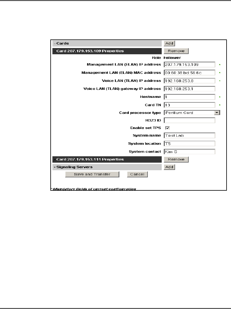
Page 774 of 910 Voice Gateway Media Card maintenance using Element Manager
553-3001-365 Standard 4.00 August 2005
See Figure 239.
Figure 239
Cards
11 Change the Management LAN (ELAN) MAC address field to the MAC
address of the replacement Voice Gateway Media Card.
The MAC address is the Motherboard Ethernet address labeled on the
faceplate of the replacement Voice Gateway Media Card.
12 Click Save and Transfer.
The Node Configuration window opens.
13 Click the Transfer/Status button associated with the node containing the
Voice Gateway Media Card.
14 After the transfer is complete, restart the new card.

Voice Gateway Media Card maintenance using Element Manager Page 775 of 910
IP Line Description, Installation and Maintenance
Restarting the card causes the follower card to obtains its BOOTP
parameters from the Leader, and also establishes ELAN and TLAN
subnet connectivity.
15 Follow the steps in Procedure 38 on page 411 to load the CONFIG.INI file
onto the card.
16 Follow the steps in Procedure 43 on page 427 to download the latest
software to the Voice Gateway Media Card.
17 Follow the steps in Procedure 44 on page 432 to reboot the card and run
the new software.
18 Follow the steps in Procedure 46 on page 438 to update the card’s
firmware.
End of Procedure
Replace a Leader Voice Gateway Media Card
To replace a Leader Voice Gateway Media Card, follow the steps in
Procedure 109.
Procedure 109
Replacing a Leader Voice Gateway Media Card
1Locate the faulty card by the TN, MAC address, and IP address.
2Disable the faulty Voice Gateway Media Card in LD 32 with the DISI
command.
The system outputs “NPR0011” when the card has been completely
disabled by the DISI command.
3Use the disiTPS command at the IPL> CLI to disable the LTPS on the
faulty Voice Gateway Media Card.
This forces all IP Phones registered on this card to reregister. If there are
sufficient resources, this can take up to several minutes. If there are not
sufficient resources, IP Phones can remain unregistered indefinitely.
4Use the isetShow command to monitor the status of the card and the
re-registration of the IP Phones.
The Voice Gateway Media Card is completely disabled when no IP
Phones are registered on the card.
5Remove the faulty Voice Gateway Media Card from the system.

Page 776 of 910 Voice Gateway Media Card maintenance using Element Manager
553-3001-365 Standard 4.00 August 2005
6Install the replacement Voice Gateway Media Card into the card slot in the
system. To do this:
a. Pull the top and bottom locking devices away from the card faceplate.
b. Insert the Voice Gateway Media Card into the card guides and gently
push the card until it makes contact with the backplane connector.
Hook the locking devices.
Note 1: When cards are installed, the red LED on the faceplate remains
lit until the card is configured and enabled in the software, at which point
in turns off. If the LED does not follow the pattern described or operates
in any other manner (such as continually flashing or remaining weakly lit),
replace the card.
Note 2: Observe the faceplate maintenance display to see start-up
self-test results and status messages. A display of the type F:xx indicates
a failure. Refer to Table 79 on page 689 for a listing of the ITG-P 24-port
line card’s display codes and to Table 80 on page 691 for a listing of the
Media Card’s display codes.
7Go to the VxWorks shell. Configure the Voice Gateway Media Card as a
Leader using the ELAN network interface IP address and subnet mask.
8Restart the card.
The card obtains the ELAN network interface IP address and subnet
mask.
9In the Element Manager navigator, click IP Telephony > Nodes:
Servers, Media Cards > Configuration.
The Node Configuration window opens.
10 Click the Edit button associated with the node containing the card to be
replaced.
The Edit window opens.
11 Expand the Cards section by clicking the plus sign (+) to the left of Cards.
12 Select the Voice Gateway Media Card from the list of cards in the node.
See Figure 239 on page 774.
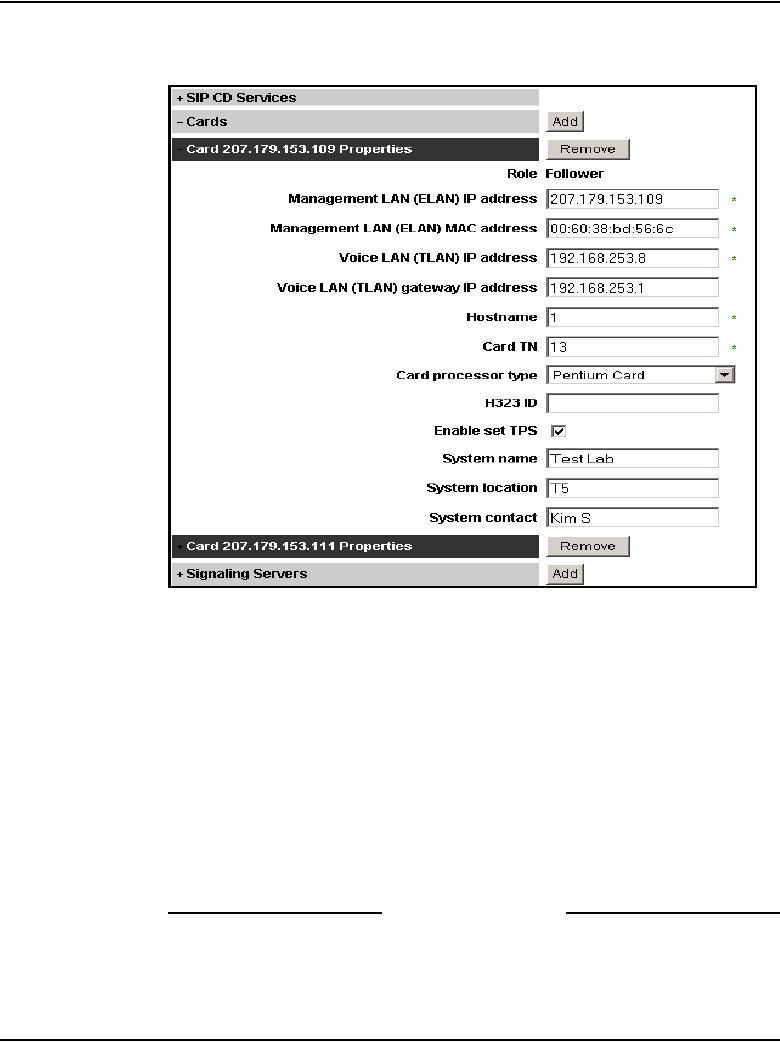
Voice Gateway Media Card maintenance using Element Manager Page 777 of 910
IP Line Description, Installation and Maintenance
Figure 240
Cards
13 Change the Management LAN (ELAN) MAC address field to the MAC
address of the replacement Voice Gateway Media Card. The MAC
address is the Motherboard Ethernet address labeled on the faceplate of
the replacement Voice Gateway Media Card.
14 Follow the steps in Procedure 43 on page 427 to download the latest
software to the Voice Gateway Media Card.
15 Follow the steps in Procedure 44 on page 432 to reboot the card and run
the new software.
16 Follow the steps in Procedure 46 on page 438 to update the card’s
firmware.
End of Procedure

Page 778 of 910 Voice Gateway Media Card maintenance using Element Manager
553-3001-365 Standard 4.00 August 2005
Verify Voice Gateway Media Card loadware and firmware
The following steps are required to verify and upgrade the card loadware and
IP Phone firmware:
1Check the version of the loadware currently installed on the Voice
Gateway Media Card. Refer to Procedure 39 on page 420.
2Check the version of the firmware that is currently running on the Voice
Gateway Media Card. Refer to Procedure 40 on page 423.
3Download the most up-to-date version of the loadware and firmware files
from the Nortel web site. Refer to Procedure 41 on page 424.
4Upload the loadware and firmware files using the File Upload system
utility in Element Manager. Refer to Procedure 42 on page 426.
5Upgrade the Voice Gateway Media Card software. Refer to Procedure 43
on page 427.
6Restart the Voice Gateway Media Card. Refer to Procedure 44 on
page 432.
7Upgrade and distribute the firmware to the IP Phones on the Voice
Gateway Media Card. Refer to Procedure 46 on page 438.
Add another Voice Gateway Media Card
Follow the steps in Procedure 110 to add another Voice Gateway Media Card
to the system.
Procedure 110
Add another Voice Gateway Media Card to the system
1Install and cable the Voice Gateway Media Card, as described in “Install
the hardware components” on page 312.
2Go to the VxWorks shell. Configure the Voice Gateway Media Card as a
Follower using the ELAN network interface IP address and subnet mask.
Restart the card.
The card obtains the ELAN network interface IP address and subnet
mask.
3In the Element Manager navigator, click IP Telephony > Nodes:
Servers, Media Cards > Configuration.
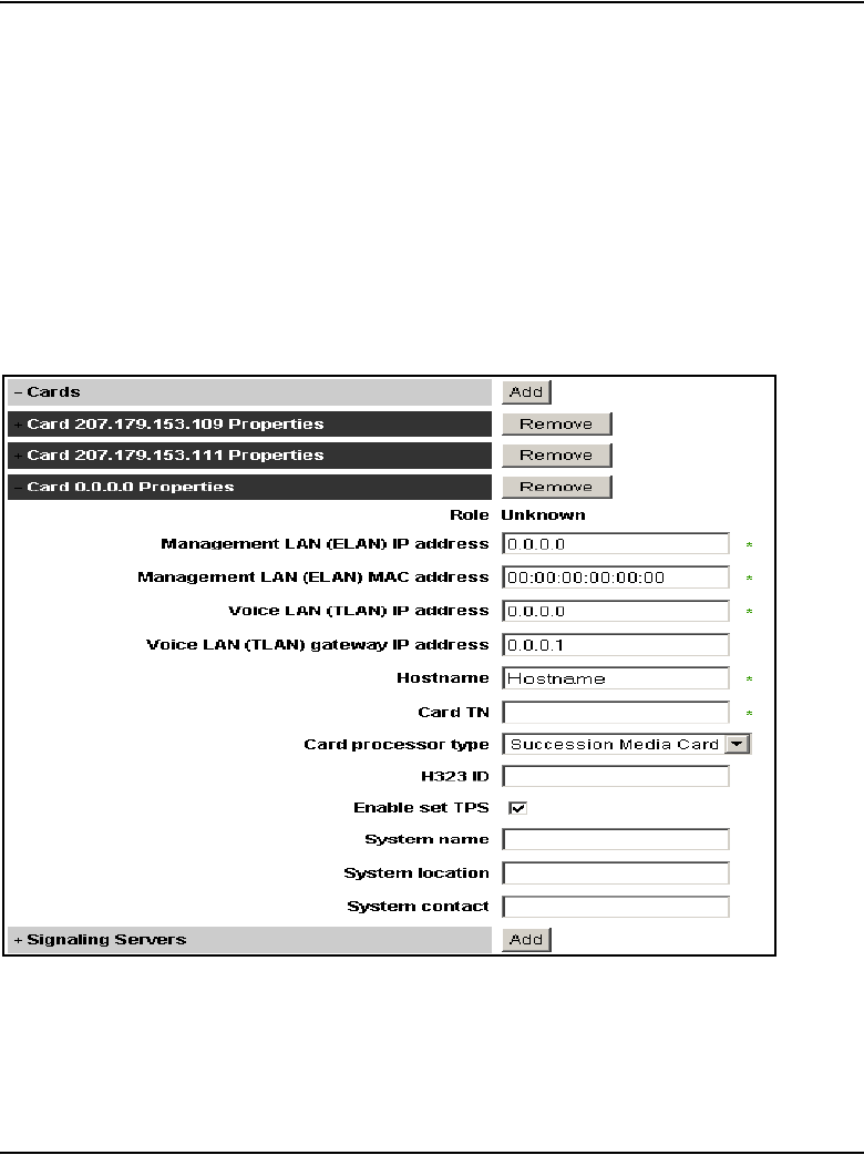
Voice Gateway Media Card maintenance using Element Manager Page 779 of 910
IP Line Description, Installation and Maintenance
The Node Configuration window opens.
4Click the Edit button associated with the node containing the card to be
replaced.
The Edit window opens.
5Expand the Cards section by clicking the plus sign (+) to the left of Cards.
6Click Cards and then click the Add button.
The fields to be configured for the new card are displayed. See
Figure 241.
Figure 241
Configuration > Node Summary > Edit > Cards

Page 780 of 910 Voice Gateway Media Card maintenance using Element Manager
553-3001-365 Standard 4.00 August 2005
7Enter the Card Properties data.
a. Role: The role is assigned based on the information that Element
Manager reads from the card configuration. This is a read-only field.
b. Management LAN (ELAN) IP address: This is the ELAN network
interface IP address for the card. Element Manager and the system
use this address to communicate with the card.
c. Management LAN (ELAN) MAC address: The MAC address is the
Motherboard Ethernet address labeled on the faceplate of the Voice
Gateway Media Card.
d. Voice LAN (TLAN) IP address: This is the TLAN network interface
IP address for the card.
e. Voice LAN (TLAN) gateway IP address: This is the IP address of
the router interface on the TLAN subnet.
f. Hostname: This is the Host name.
g. Card TN: Enter the card slot number between 1 – 50.
h. Card processor type: Choose either Pentium or Media Card. Select
Pentium if using the ITG-P 24-port line card (dual-slot card). Select
Media Card if using the Media Card 32-port or 8-port line card
(single-slot card).
i. H323 ID: The H323 ID within IP Line 4.5 is for the Virtual Office/
Media Gateway 1000B feature. Keep the H323 ID the same for all the
elements within one node.
j. Enable set TPS: Select the check box.
k. System name: Enter the name of the system.
l. System location: Enter the location where the system resides.
m. System contact: Enter a contact name and telephone number.
8Click Save and Transfer.
The Node Configuration window opens.
9Click the Transfer/Status button associated with the node containing the
Voice Gateway Media Card.
10 After the transfer is complete, restart the new card.

Voice Gateway Media Card maintenance using Element Manager Page 781 of 910
IP Line Description, Installation and Maintenance
Restarting the card causes the follower card to obtain its BOOTP
parameters from the Leader, and also establishes ELAN and TLAN
subnet connectivity.
11 Follow the steps in Procedure 38 on page 411 to load the CONFIG.INI file
onto the card.
12 Follow the steps in Procedure 43 on page 427 to download the latest
software to the Voice Gateway Media Card.
13 Follow the steps in Procedure 44 on page 432 to reboot the card and run
the new software.
14 Follow the steps in Procedure 46 on page 438 to update the card’s
firmware.
End of Procedure
Access CLI commands from Element Manager
Table 109 lists the informational CLI commands (by group) available from
Element Manager for the Voice Gateway Media Cards.
Table 109
Informational CLI commands by group for Voice Gateway Media Card (Part 1 of 3)
Group Command
Dsp dspSWVersion Show
dSPNumShow
Election electShow
Iset isetShow
isetNATShow
isetFWShow
isetFWGet
Mam disServices
enlServices

Page 782 of 910 Voice Gateway Media Card maintenance using Element Manager
553-3001-365 Standard 4.00 August 2005
forcedisServices
IPinfoShow
itgCardShow
servicesStatusShow
NodePwd nodePwdDisable
nodePwdEnable
nodePwdShow
nodeTempPwdClear
nodePwdSet
nodeTempPwdSet
pbxLink pbxLinkShow
QoS isetInfoShow
RTPStatShow
rping
rTraceRoute
System i
ifShow
routeShow
rudpShow
Tps disTPS
enlTPS
forcedisTPS
Table 109
Informational CLI commands by group for Voice Gateway Media Card (Part 2 of 3)
Group Command

Voice Gateway Media Card maintenance using Element Manager Page 783 of 910
IP Line Description, Installation and Maintenance
loadBalance
echoServerShow
Ums umsPolicyshow
Vgw vgwShowAll
Print VGW Channels
Misc cardRoleShow
ipstatShow
Table 109
Informational CLI commands by group for Voice Gateway Media Card (Part 3 of 3)
Group Command

Page 784 of 910 Voice Gateway Media Card maintenance using Element Manager
553-3001-365 Standard 4.00 August 2005
Table 110 lists the informational CLI commands (by group) available from
Element Manager for the for the Signaling Server.
Table 110
Informational CLI commands by group for Signaling Server (Part 1 of 3)
Group Command
Election electShow
Iset isetShow
isetNATShow
isetFWShow
isetFWGet
Mam disServices
enlServices
forcedisServices
IPinfoShow
itgCardShow
servicesStatusShow
NodePwd nodePwdDisable
nodePwdEnable
nodePwdShow
nodeTempPwdClear
nodePwdSet
nodeTempPwdSet
pbxLink pbxLinkShow
QoS isetInfoShow
RTPStatShow

Voice Gateway Media Card maintenance using Element Manager Page 785 of 910
IP Line Description, Installation and Maintenance
rping
rTraceRoute
Sip SIPGwShow
SIPGwShowch
SIPGwShownum
System i
ifShow
routeShow
rudpShow
Tps disTPS
enlTPS
forcedisTPS
loadBalance
echoServerShow
Uftp uftpTurboMode
uftpTurboModeShow
uftpTurboModeTimeoutSet
uftpAutoupgradeTimeoutSet
Ums umsPolicyshow
Vtrk vtrkShow
disVTRK
enlVTRK
Table 110
Informational CLI commands by group for Signaling Server (Part 2 of 3)
Group Command

Page 786 of 910 Voice Gateway Media Card maintenance using Element Manager
553-3001-365 Standard 4.00 August 2005
Refer to “IP Line CLI commands” on page 710 for descriptions of these
commands.
To access these commands in Element Manager, follow the steps in
Procedure 111.
Procedure 111
Accessing the CLI commands from Element Manager
1In the Element Manager navigator, click IP Telephony > Nodes:
Servers, Media Cards > Maintenance and Reports.
The Node Maintenance and Reports window opens.
2Expand the node containing the Voice Gateway Media Card by clicking
the plus sign (+) to the left of the Node ID.
3Click the GEN CMD button associated with the Voice Gateway Media
Card.
The General Commands window opens. See Figure 242 on page 787.
forcedisVTRK
Misc cardRoleShow
DCHstatus
help
ipstatShow
Table 110
Informational CLI commands by group for Signaling Server (Part 3 of 3)
Group Command
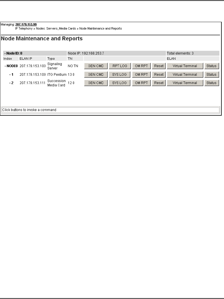
Voice Gateway Media Card maintenance using Element Manager Page 787 of 910
IP Line Description, Installation and Maintenance
Figure 242
General Commands
Note: The line shown on the top of the General Commands window,
under General Commands, displays the IP address of the element and
what the selected element is, as follows:
• ITG Pentium – ITG-P 24-port card
• Media Card – Media Card 8-port or 32-port card
• SS – Signaling Server
See Figure 243 on page 788.

Page 788 of 910 Voice Gateway Media Card maintenance using Element Manager
553-3001-365 Standard 4.00 August 2005
Figure 243
General Commands window
4Select the CLI command group from the Group drop-down list box, select
the CLI command from the Command drop-down list, and click RUN.
The output of the command is displayed in the text area at the bottom of
the General Commands window.
End of Procedure
Sample Output of Element Manager CLI commands
cardRoleShow
Card Role = Follower
dspSWVersionShow
DSP software version R8.01
DSPNumShow
Number of DSPs = 8
electShow
The following is an example of the output on a Signaling Server:
oam> electShow
Node ID : 541
Node Master : No

Voice Gateway Media Card maintenance using Element Manager Page 789 of 910
IP Line Description, Installation and Maintenance
Up Time : 10 days, 3 hours, 5 mins, 30 secs
TN : 10 00
Host Type : SMC
TLAN IP Addr : 47.11.151.148
ELAN IP Addr : 47.11.221.48
Election Duration : 15
Wait for Result time : 35
Master Broadcast period : 30
===== master tps =====
Host Type TN TLAN IP Addr
ISP 1100 00 00 47.11.151.144
Next timeout : 30 sec
AutoAnnounce : 1
Timer duration : 60 (Next timeout in 7 sec)
====== all tps ======
Num TN Host Type ELAN MAC TLAN
IP Addr ELAN IP Addr Up Time NumOfSets
TimeOut
001 10 00 SMC 00:60:38:bd:d1:01
47.11.151.148 47.11.221.48 010 03:05:30 0
0
002 00 00 ISP 1100 00:02:b3:c5:51:2c
47.11.151.144 47.11.221.38 010 05:24:41 0
-73
====== All cards in node configuration are
registered ======
Note: When all cards configured in a node are registered, the last part of
the output displays the following:
====== All cards in node configuration are
registered ======

Page 790 of 910 Voice Gateway Media Card maintenance using Element Manager
553-3001-365 Standard 4.00 August 2005
+master tps
PlatForm TN TLAN
ISP 1100 0000 47.104.39.245
Next timeout = 71 sec
AutoAnnounce: 1
Timer duration : 60 (Next timeout in 25 sec)
all tps
i
Num Platform TN TLAN ELAN TimeOut
0 ITG SA 080c 47.104.39.243 47.104.39.115 0
1 ISP 1100 0000 47.104.39.246 47.104.39.118 0
2 ISP 1100 0000 47.104.39.245 47.104.39.117 0
3 ITG SA 0c04 47.104.39.244 47.104.39.116 1
NAME ENTRY TID PRI STATUS PC SP ERRNO DELAY
tExcTask _excTask 339a824 0 PEND 2aca80 339a758 3006b 0
tShell _shell 2e31e30 1 PEND 231e08 2e316d4 0 0
... ... ... ... ... ... ... ... ...
tSET 19be9c 2b6263c 200 PEND 256d84 2b62518 320001 0
tSyslogd 10a58 3aff168 255 READY 22f6d0 3afeac4 0 0

Voice Gateway Media Card maintenance using Element Manager Page 791 of 910
IP Line Description, Installation and Maintenance
ifShow
ixpMac (unit number 1):
Flags: (0x8863) UP BROADCAST MULTICAST ARP RUNNING
Type: ETHERNET_CSMACD
Internet address: 47.104.39.115
Broadcast address: 47.104.39.127
Netmask 0xff000000 Subnetmask 0xffffff80
Ethernet address is 00:60:38:bd:bb:cd
Metric is 0
Maximum Transfer Unit size is 1500
298604 packets received; 23909 packets sent
278631 multicast packets received
4608 multicast packets sent
0 input errors; 0 output errors
0 collisions; 0 dropped
lo (unit number 0):
Flags: (0x8069) UP LOOPBACK MULTICAST ARP RUNNING
Type: SOFTWARE_LOOPBACK
Internet address: 127.0.0.1
Netmask 0xff000000 Subnetmask 0xff000000
Metric is 0
Maximum Transfer Unit size is 32768
4 packets received; 4 packets sent
0 multicast packets received
0 multicast packets sent
0 input errors; 0 output errors
0 collisions; 0 dropped
ixpMac (unit number 0):
Flags: (0x8863) UP BROADCAST MULTICAST ARP RUNNING
Type: ETHERNET_CSMACD
Internet address: 47.104.39.243
Broadcast address: 47.104.39.255
Netmask 0xff000000 Subnetmask 0xffffff80
Ethernet address is 00:60:38:bd:bb:cc
Metric is 0
Maximum Transfer Unit size is 1500
88686 packets received; 15027 packets sent
78030 multicast packets received
5044 multicast packets sent
0 input errors; 0 output errors
0 collisions; 0 dropped

Page 792 of 910 Voice Gateway Media Card maintenance using Element Manager
553-3001-365 Standard 4.00 August 2005
IPInfoShow
Maintenance Interface = ixpMac1
Maintenance IP address = 47.104.39.115
Maintenance subnet mask = 255.255.255.128
Voice Interface = ixpMac0
Voice IP address = 47.104.39.243
Voice subnet mask = 255.255.255.128
ROUTE NET TABLE
ROUTE HOST TABLE
ipstatShow
total 128099
badsum 0
tooshort 0
toosmall 0
badhlen 0
badlen 0
infragments 0
fragdropped 0
fragtimeout 0
forward 0
cantforward 486
redirectsent 0
unknownprotocol 0
nobuffers 0
reassembled 0
outfragments 0
noroute 0
destination gateway flags Refcnt Use Interface
0.0.0.0 47.104.39.129 3 0 675 ixpMac0
47.104.39.0 47.104.39.115 101 0 0 ixpMac1
47.104.39.128 47.104.39.243 101 0 0 ixpMac0
destination gateway flags Refcnt Use Interface
127.0.0.1 127.0.0.1 5 0 0 lo0

Voice Gateway Media Card maintenance using Element Manager Page 793 of 910
IP Line Description, Installation and Maintenance
isetShow
itgCardShow
Index : 2
Type : EXUT
Role : Follower
Node : 541
Leader IP : 47.11.151.145
Card IP : 47.11.151.148
Card TN : Slot 10
Card State : ENBL
Uptime : 10 days, 3 hours, 11 mins, 24
secs (875484 secs)
Codecs : G711Ulaw(default), G711Alaw,
G711CC, T38FAX
ELAN (ixpMac1) stat: 10 Mbps, Half duplex (Carrier
OK)
TLAN (ixpMac0) stat: 100 Mbps, Full duplex (Carrier
OK)

Page 794 of 910 Voice Gateway Media Card maintenance using Element Manager
553-3001-365 Standard 4.00 August 2005
nodePasswordDisable
Please run nodePwdShow to verify the result.
Run nodePwdShow and get the following results:
nodePasswordEnable
Please run nodePwdShow to verify the result.
Run nodePwdShow and get the following results:
nodePasswordShow
nodeTempPwdClear
Please run nodePwdShow to verify the result.
Run nodePwdShow and get the following results:
pbxLinkShow
Active CS type = CS 1K
Active CS S/W Release = 201R
Supported Features: GetCSVsn TCP ShiftKey I2050
I2002 CorpDir UserKeyLabel VirtualOffice UseCSPwd
CS Main: ip = 47.104.39.112, ConnectID = 0x2bbfb4c,
BroadcastID = 0x2bc059c, Link is up
CS Signaling Port = 15000
NodeID
======
PwdEna
=======
Pwd
====
TmpPwd
=======
Uses
====
TimeOut
========
444 No 0 0d 0h 0m 0s
NodeID
======
PwdEna
=======
Pwd
====
TmpPwd
=======
Uses
====
TimeOut
========
444 No 0 0d 0h 0m 0s
NodeID
======
PwdEna
=======
Pwd
====
TmpPwd
=======
Uses
====
TimeOut
========
444 No 0 0d 0h 0m 0s
NodeID
======
PwdEna
=======
Pwd
====
TmpPwd
=======
Uses
====
TimeOut
========
444 No 0 0d 0h 0m 0s

Voice Gateway Media Card maintenance using Element Manager Page 795 of 910
IP Line Description, Installation and Maintenance
CS Broadcast Port = 15001
Broadcast PortID = 0x2bc06fc
RUDP portID = 0x2bc0684
Tcp Link state = up
Tcp Signaling Port: 15000
Tcp socket fd: 30
Tcp msgs sent: 77
Tcp msgs recd: 47
routeShow
ROUTE NET TABLE
ROUTE HOST TABLE
rudpdShow
RUDP Port Summary
Port ID Src IP Src Port
+----------+---------------+--------+
0x02bcb904 0.0.0.0 15001
0x02bcb878 47.11.221.48 15000
0x02b4b748 47.11.151.148 7300
0x0231d808 47.11.151.148 5100
destination gateway flags Refcnt Use Interface
0.0.0.0 47.104.39.129 3 0 675 ixpMac0
47.104.39.0 47.104.39.115 101 0 0 ixpMac1
47.104.39.128 47.104.39.243 101 0 0 ixpMac0
destination gateway flags Refcnt Use Interface
127.0.0.1 127.0.0.1 5 0 0 lo0

Page 796 of 910 Voice Gateway Media Card maintenance using Element Manager
553-3001-365 Standard 4.00 August 2005
RUDP Connection Summary
umsPolicyShow
Total firmware = 2
Src IP Src Port Connect ID Dst IP Dst
Port
Status Msg rcv Msg sent Retries
0.0.0.0 15001 0x02bcb77c 47.11.221.41 15000 DUDP 1 0 0
47.11.221.48
15000 0x02bcad18 47.11.221.41 15000 Established 2 44305 3075
FirmWare TermType PolicyName Server FileName Limit When Upgrade Protocol Retry
0602B38 i2004 DEFAULT_
I2004
47.104.39.243 /ums/i2004.fw 10 ALWAYS ANY TFTP -1
0603B38 i2002 DEFAULT_
I2002
47.104.39.245 /ums/i2002.fw 10 ALWAYS ANY TFTP -1

Voice Gateway Media Card maintenance using Element Manager Page 797 of 910
IP Line Description, Installation and Maintenance
vgwShowAll
VGW Service is: Enabled
Chan ChanState DspMode Codec Tn Reg AirTime rxTsap txTsap
0 Idle Closed n/a 0x080c yes 0 0.0.0.0:0000 0.0.0.0:0000
1 Idle Closed n/a 0x080d yes 0 0.0.0.0:0000 0.0.0.0:0000
2 Idle Closed n/a 0x080e yes 0 0.0.0.0:0000 0.0.0.0:0000
3 Idle Closed n/a 0x080f yes 0 0.0.0.0:0000 0.0.0.0:0000
4 Idle Closed n/a 0x084c yes 0 0.0.0.0:0000 0.0.0.0:0000
5 Idle Closed n/a 0x084d yes 0 0.0.0.0:0000 0.0.0.0:0000
6 Idle Closed n/a 0x084e yes 0 0.0.0.0:0000 0.0.0.0:0000
7 Idle Closed n/a 0x084f yes 0 0.0.0.0:0000 0.0.0.0:0000
8 Idle Closed n/a 0x088c yes 0 0.0.0.0:0000 0.0.0.0:0000
9 Idle Closed n/a 0x088d yes 0 0.0.0.0:0000 0.0.0.0:0000
10 Idle Closed n/a 0x088e yes 0 0.0.0.0:0000 0.0.0.0:0000
11 Idle Closed n/a 0x088f yes 0 0.0.0.0:0000 0.0.0.0:0000
12 Idle Closed n/a 0x08cc yes 0 0.0.0.0:0000 0.0.0.0:0000
13 Idle Closed n/a 0x08cd yes 0 0.0.0.0:0000 0.0.0.0:0000
14 Idle Closed n/a 0x08ce yes 0 0.0.0.0:0000 0.0.0.0:0000
15 Idle Closed n/a 0x08cf yes 0 0.0.0.0:0000 0.0.0.0:0000
16 Idle Closed n/a 0x090c yes 0 0.0.0.0:0000 0.0.0.0:0000
17 Idle Closed n/a 0x090d yes 0 0.0.0.0:0000 0.0.0.0:0000
18 Idle Closed n/a 0x090e yes 0 0.0.0.0:0000 0.0.0.0:0000
19 Idle Closed n/a 0x090f yes 0 0.0.0.0:0000 0.0.0.0:0000
20 Idle Closed n/a 0x094c yes 0 0.0.0.0:0000 0.0.0.0:0000
21 Idle Closed n/a 0x094d yes 0 0.0.0.0:0000 0.0.0.0:0000
22 Idle Closed n/a 0x094e yes 0 0.0.0.0:0000 0.0.0.0:0000
23 Idle Closed n/a 0x094f yes 0 0.0.0.0:0000 0.0.0.0:0000
24 Idle Closed n/a 0x098c yes 0 0.0.0.0:0000 0.0.0.0:0000
25 Idle Closed n/a 0x098d yes 0 0.0.0.0:0000 0.0.0.0:0000
26 Idle Closed n/a 0x098e yes 0 0.0.0.0:0000 0.0.0.0:0000
27 Idle Closed n/a 0x098f yes 0 0.0.0.0:0000 0.0.0.0:0000
28 Idle Closed n/a 0x09cc yes 0 0.0.0.0:0000 0.0.0.0:0000
29 Idle Closed n/a 0x09cd yes 0 0.0.0.0:0000 0.0.0.0:0000
30 Idle Closed n/a 0x09ce yes 0 0.0.0.0:0000 0.0.0.0:0000
31 Idle Closed n/a 0x09cf yes 0 0.0.0.0:0000 0.0.0.0:0000


Page 799 of 910
IP Line Description, Installation and Maintenance
816
Voice Gateway Media Card maintenance
using OTM 2.2
Contents
This section contains information on the following topics:
Introduction . . . . . . . . . . . . . . . . . . . . . . . . . . . . . . . . . . . . . . . . . . . . . . 799
Replace a Voice Gateway Media Card . . . . . . . . . . . . . . . . . . . . . . . . . 800
Replace a Leader Voice Gateway Media Card. . . . . . . . . . . . . . . . . 801
Replace a Follower Voice Gateway Media Card . . . . . . . . . . . . . . . 803
Verify the Voice Gateway Media Card loadware and firmware . . . 805
Transmit card properties to the cards . . . . . . . . . . . . . . . . . . . . . . . . 807
Access the IPL> CLI from OTM . . . . . . . . . . . . . . . . . . . . . . . . . . . . . 809
Add a “dummy” node for retrieving and viewing IP Telephony node
configuration . . . . . . . . . . . . . . . . . . . . . . . . . . . . . . . . . . . . . . . . . . . . . . . . . . 809
Retrieve IP Line configuration from the IP Telephony node . . . . . . 815
Introduction
This chapter provides information on using Optivity Telephony Management
(OTM) 2.2 to perform maintenance functions on the Voice Gateway Media
Card.

Page 800 of 910 Voice Gateway Media Card maintenance using OTM 2.2
553-3001-365 Standard 4.00 August 2005
Where reference is made to OTM, the latest version, OTM 2.2, is assumed.
Replace a Voice Gateway Media Card
Replace the Voice Gateway Media Card when the card is removed or when
the following conditions occur:
• If the Voice Gateway Media Card displays a code of the form F:xx on the
faceplate LED following a reboot, this indicates an unrecoverable
hardware failure. The card cannot register with the systems. The
exception is the F:10 code, which indicates that the Security Device is
missing from the card.
• If the Management (ELAN) network interface or the Voice (TLAN)
network interface on the Voice Gateway Media Card has failed. This is
indicated by failing to show a link pulse on the voice IP interface status
LED or on the switch. It can also be indicated if the maintenance port
continuously prints ‘lnIsa0 Carrier Failure’ messages after determining
that the hub or switch port and ELAN cable are good.
• If a voice channel on the Voice Gateway Media Card has a consistent
voice quality fault. For example, persistent noise or lack of voice path,
even after resetting the card and retransmitting the card properties.
Note: There are separate procedures for replacing a Leader Voice
Gateway Media Card and a Follower Voice Gateway Media Card. Be
aware of the role the card is to play before replacing the card.
CAUTION
This procedure is not supported for a node that resides
on a CS 1000 system.

Voice Gateway Media Card maintenance using OTM 2.2 Page 801 of 910
IP Line Description, Installation and Maintenance
Replace a Leader Voice Gateway Media Card
To replace a Leader Voice Gateway Media Card, follow the steps in
Procedure 112.
Procedure 112
Replacing a Leader Voice Gateway Media Card
1Locate the faulty card in the OTM IP Telephony database by the TN, MAC
address, and IP address.
2Disable the faulty Voice Gateway Media Card in LD 32 with the DISI
command. The system displays “NPR0011” when the card has been
completely disabled by the DISI command.
3Use the disiTPS command at the IPL> CLI to disable the LTPS on the
faulty Voice Gateway Media Card.
Note: This forces all Internet Telephones registered on this card to
reregister. If there are sufficient resources, this can take up to several
minutes. If there are not sufficient resources, Internet Telephones can
remain unregistered indefinitely.
4Use the isetShow command to monitor the status of the card and the
reregistration of the IP Phone. The Voice Gateway Media Card is
completely disabled when no IP Phones are registered on the card.
5Remove the faulty Voice Gateway Media Card from the system.
6Install the replacement Voice Gateway Media Card into the card slots in
the Meridian 1/ CS 1000M IPE module, Option 11C/CS 1000M Cabinet,
CS 1000E Media Gateway 1000E/Media Gateway 1000E Expander,
CS 1000S Media Gateway 1000S/Media Gateway 1000S Expander. To
do this:
a. Pull the top and bottom locking devices away from the card faceplate.
b. Insert the Voice Gateway Media Card into the card guides and gently
push it until it makes contact with the backplane connector. Hook the
locking devices.
CAUTION
This procedure is not supported for a node that resides
on a CS 1000 system.

Page 802 of 910 Voice Gateway Media Card maintenance using OTM 2.2
553-3001-365 Standard 4.00 August 2005
Note 1: When cards are installed, the red LED on the faceplate remains
lit until the card is configured and enabled in the software, at which point
the red LED turns off. If the LED does not follow the pattern described or
operates in any other manner (such as continually flashing or remaining
weakly lit), replace the card.
Note 2: Observe the faceplate maintenance display to see start-up
self-test results and status messages. A display of the type F:xx indicates
a failure. Refer to Table 79 on page 689 for a listing of the ITG-P 24-port
line card’s display codes and to Table 80 on page 691 for a listing of the
Media Card’s display codes.
7Follow the steps in Procedure 61 “Configuring the Leader 0 IP address”
on page 497 to configure the new card as a Leader card.
8In the OTM Navigator, select the Services folder. Double-click on the IP
Telephony icon. The IP Telephony window opens. Select the node in the
upper part of the window.
9Click on Leader 0 or any Voice Gateway Media Card in the node.
10 Click Configuration > Node > Properties. The Node Properties window
opens.
11 Click the Configuration tab.
12 Select the card to be replaced.
13 Change the Management MAC to the MAC address of the replacement
Voice Gateway Media Card. The MAC address is the Motherboard
Ethernet address labeled on the faceplate of the replacement Voice
Gateway Media Card.
14 Click Change, and then OK.
15 Select Leader 0 or any Voice Gateway Media Card in the node in the
IP Telephony window.
16 Use the Configuration > Synchronize > Transmit. The Transmit
Options window opens.
17 Under Transmit options, select the Transmit to Selected Nodes radio
button and check the Node Properties to Active Leader check box.
18 Click Start transmit. This updates the node properties on the active
Leader card with the MAC Address of the replacement Voice Gateway
Media Card. The results of the transmit are displayed under Transmit
control. When the transmit is successful, click Close.

Voice Gateway Media Card maintenance using OTM 2.2 Page 803 of 910
IP Line Description, Installation and Maintenance
19 In the OTM IP Telephony window, select View > Refresh and verify that
the replacement Voice Gateway Media Card state is showing
“Unequipped.”
End of Procedure
Replace a Follower Voice Gateway Media Card
Follow the steps in Procedure 113 to replace a Follower Voice Gateway
Media Card.
Procedure 113
Replacing a Follower Voice Gateway Media Card
1Locate the faulty card in the OTM IP Telephony database by the TN, MAC
address, and IP address.
2Disable the faulty Voice Gateway Media Card in LD 32 with the DISI
command. The system displays “NPR0011” when the card has been
completely disabled by the DISI command.
3Use the disiTPS command at the IPL> CLI to disable the LTPS on the
faulty Voice Gateway Media Card.
Note: This forces all IP Phones registered on this card to reregister. If
there are sufficient resources, this can take up to several minutes. If there
are not sufficient resources, IP Phones can remain unregistered
indefinitely.
4Use the isetShow command to monitor the status of the card and the
reregistration of the IP Phones. The Voice Gateway Media Card card is
completely disabled when there are no IP Phones registered on the card.
5Remove the faulty Voice Gateway Media Card from the system.
6In the OTM Navigator, select the Services folder. Double-click on the IP
Telephony icon. The IP Telephony window opens. Select the node in the
upper part of the window.
7Click on Leader 0 or any Voice Gateway Media Card in the node.
8Click Configuration > Node > Properties. The Node Properties window
opens.
9Click the Configuration tab.
10 Select the card to be replaced.

Page 804 of 910 Voice Gateway Media Card maintenance using OTM 2.2
553-3001-365 Standard 4.00 August 2005
11 Change the Management MAC to the MAC address of the replacement
Voice Gateway Media Card. The MAC address is the Motherboard
Ethernet address labeled on the faceplate of the replacement Voice
Gateway Media Card.
12 Click Change, and then OK.
13 Select Leader 0 or any Voice Gateway Media Card in the node in the
IP Telephony window.
14 Use the Configuration > Synchronize > Transmit. The Transmit
Options window opens.
15 Under Transmit options, select the Transmit to Selected Nodes radio
button and check the Node Properties to Active Leader check box.
16 Click Start transmit. This updates the node properties on the active
Leader card with the MAC Address of the replacement Voice Gateway
Media Card. The results of the transmit are displayed under Transmit
control. When the transmit is successful, click Close.
17 Install the replacement Voice Gateway Media Card into the card slots in
the Meridian 1/CS 1000M IPE module, Option 11C/CS 1000M Cabinet,
CS 1000E Media Gateway 1000E/Media Gateway 1000E Expander, or
CS 1000S Media Gateway 1000S/Media Gateway 1000S Expander. To
do this:
a. Pull the top and bottom locking devices away from the card faceplate.
b. Insert the Voice Gateway Media Card into the card guides and gently
push it until it makes contact with the backplane connector. Hook the
locking devices.
Note 1: When cards are installed, the red LED on the faceplate remains
lit until the card is configured and enabled in the software, at which point
the red LED turns off. If the LED does not follow the pattern described, or
operates in any other manner (such as continually flashing or remaining
weakly lit), replace the card.
18 Observe the faceplate maintenance display to see start-up self-test
results and status messages. A display of the type F:xx indicates a
failure. Refer to Table 79 on page 689 for a listing of the ITG-P 24-port
line card’s display codes and to Table 80 on page 691 for a listing of the
Media Card’s display codes.
Voice Gateway Media Card maintenance using OTM 2.2 Page 805 of 910
IP Line Description, Installation and Maintenance
19 In the OTM IP Telephony window, select View > Refresh and verify that
the replacement Voice Gateway Media Card state is showing
“Unequipped.”
End of Procedure
Verify the Voice Gateway Media Card loadware and firmware
To verify the loadware on the Voice Gateway Media Card and the firmware
on the IP Phone, follow the steps in Procedure 114.
Procedure 114
Verifying the Voice Gateway Media Card software and firmware
Note: Refer also to Procedure 64, “Verifying card loadware and IP
Phone firmware using OTM 2.2” on page 507.
1Check the Nortel Customer Support web site for the latest IP Line
software and IP Phone firmware releases. Download the appropriate IP
Line 4.5 file. See Appendix F on page 903.
• Download the IP Line 4.5xx.sa.zip for the Media Card. This zipped
file contains the IP Line 4.5 loadware for the Media Card, the IP
Phone firmware, and a readme.txt file.
• Download the IP Line 4.5xx.p2.zip for the ITG-P card. This zipped
file contains the IP Line 4.5 loadware for the ITG-P card, the IP
Phone firmware, and a readme.txt file.
CAUTION
This procedure is not supported for a node that resides
on a CS 1000 system.

Page 806 of 910 Voice Gateway Media Card maintenance using OTM 2.2
553-3001-365 Standard 4.00 August 2005
See Appendix F on page 903 for information on downloading files from
the Nortel web site.
Note: The IP Line software and IP Phone firmware files are contained in
the IP Line 4.5.xx SA file in the Internet Telephony Gateway product
list on the Nortel web site.
The zipped file contains:
•the IPL450xx.p2 and IPL450xx.sa software files. The IPL450xx.p2
file is the IP Line application for the ITG-P 24-port line card and the
IPL450xx.sa is the IP Line 4.5 application for the Media Card.
•the 0602Bxx.BIN (Phase I IP Phone 2004), 0603Bxx.BIN (Phase I
IP Phone 2002), and 0603Dnn. BIN (Phase II IP Phone 2001,
IP Phone 2002, and IP Phone 2004) firmware files.
• For example, a firmware version labeled 0602B75 means IP Phone
firmware version 1.38 where:
— The 02 represents the IP Phone 2004.
— The letter B represents the Version number 1.
— 75 represents the Release number .75.
•A readme.txt file. The readme.txt file explains important
considerations for installing the new software and firmware versions.
The readme file also includes identifying information for the software
and firmware files such as the date and time, size and checksum.
2Locate the saved file and double-click the zipped file.
The zipped file opens in a compression utility program and the
uncompressed files are listed.
3Compare the latest software and firmware versions available from the
Nortel web site with the software and firmware version currently on the
Voice Gateway Media Card.
a. In the IP Telephony window, double-click the replacement Voice
Gateway Media Card in the bottom of the window to open the Card
Properties window.
b. Leave the defaults in the Maintenance tab of the Card Properties
window. Click the Configuration tab.
c. Verify that the S/W version shows the latest recommended Voice
Gateway Media Card software version.

Voice Gateway Media Card maintenance using OTM 2.2 Page 807 of 910
IP Line Description, Installation and Maintenance
d. Verify that the IP Phone firmware version is the latest recommended
release of firmware. Click OK.
4If the card’s software and firmware are not up-to-date, transfer the
downloaded files (*.p2, *.sa, and firmware file(s)) from an
Internet-enabled PC to the OTM PC.
5Upgrade the software and/or firmware, if required. Refer to “Upgrading
Voice Gateway Media Card software from the OTM 2.2 PC” on page 512
and “Upgrading the IP Phone firmware” on page 517.
End of Procedure
Transmit card properties to the cards
To transmit card properties to the Voice Gateway Media Cards, follow the
steps in Procedure 115 on page 807.
Procedure 115
Transmitting card properties
1In the OTM Navigator, select the Services folder. Double-click on the IP
Telephony icon. The IP Telephony window opens.
2Select the replacement Voice Gateway Media Card.
3Click Configuration > Synchronize > Transmit.
The Transmit Options window opens. See Figure 244.
CAUTION
This procedure is not supported for a node that resides
on a CS 1000 system.

Page 808 of 910 Voice Gateway Media Card maintenance using OTM 2.2
553-3001-365 Standard 4.00 August 2005
Figure 244
Transmit Options dialog box
4Select the Transmit to selected cards radio button.
5Click the Start transmit button.
The transmission status is displayed under Transmit control. Confirm
that Card Properties are transmitted successfully.
6When the transmission is successful, click Close.
7Use the LD 32 ENLC command to re-enable the Voice Gateway Media
Card.

Voice Gateway Media Card maintenance using OTM 2.2 Page 809 of 910
IP Line Description, Installation and Maintenance
8Verify that the card is enabled in the IP Telephony window. Locate the
card in the list at the bottom of the screen. Look under the Card state
column and verify that the status of the card is Enabled.
9Update the Installation Summary Sheet with the new MAC address. See
“Voice Gateway Media Card installation summary sheet” on page 306.
10 Verify the TN, management interface MAC address, and IP address for
each Voice Gateway Media Card. Compare the displayed values with
those on the Voice Gateway Media Card Installation Summary Sheet.
End of Procedure
Access the IPL> CLI from OTM
To access the IPL> CLI from OTM, follow the steps in Procedure 103,
“Accessing a Voice Gateway Media Card using Telnet” on page 685.
Add a “dummy” node for retrieving and viewing
IP Telephony node configuration
Follow the steps in Procedure 116 on page 810 to create a “dummy” IP
Telephony node for retrieving and viewing the IP Telephony node
configuration, without overwriting the existing IP Line configuration data for
an existing node in the OTM IP Telephony database.
Retrieving the actual IP Telephony node configuration to the “dummy” node
is useful in the following cases:
• to isolate IP Telephony node configuration faults
• to determine which copy of the database is correct, in order to determine
the desired direction of database synchronization:
— transmit OTM IP Line to an IP Telephony node
or
— retrieve IP Telephony node to OTM IP Line
Add the dummy node manually or by retrieving the IP Telephony node
configuration data from an existing node.

Page 810 of 910 Voice Gateway Media Card maintenance using OTM 2.2
553-3001-365 Standard 4.00 August 2005
The site name, system name, and customer number must exist in the OTM
Navigator before a new IP Telephony node can be added.
Follow the steps in Procedure 116 to create the “dummy” IP Telephony node.
Procedure 116
Creating the “dummy” IP Telephony node to retrieve configuration
1In OTM Navigator, click Sites > Configuration > Add Site.
See Figure 245 on page 811.
CAUTION
This procedure in is not supported for a node that resides
on a CS 1000 system.
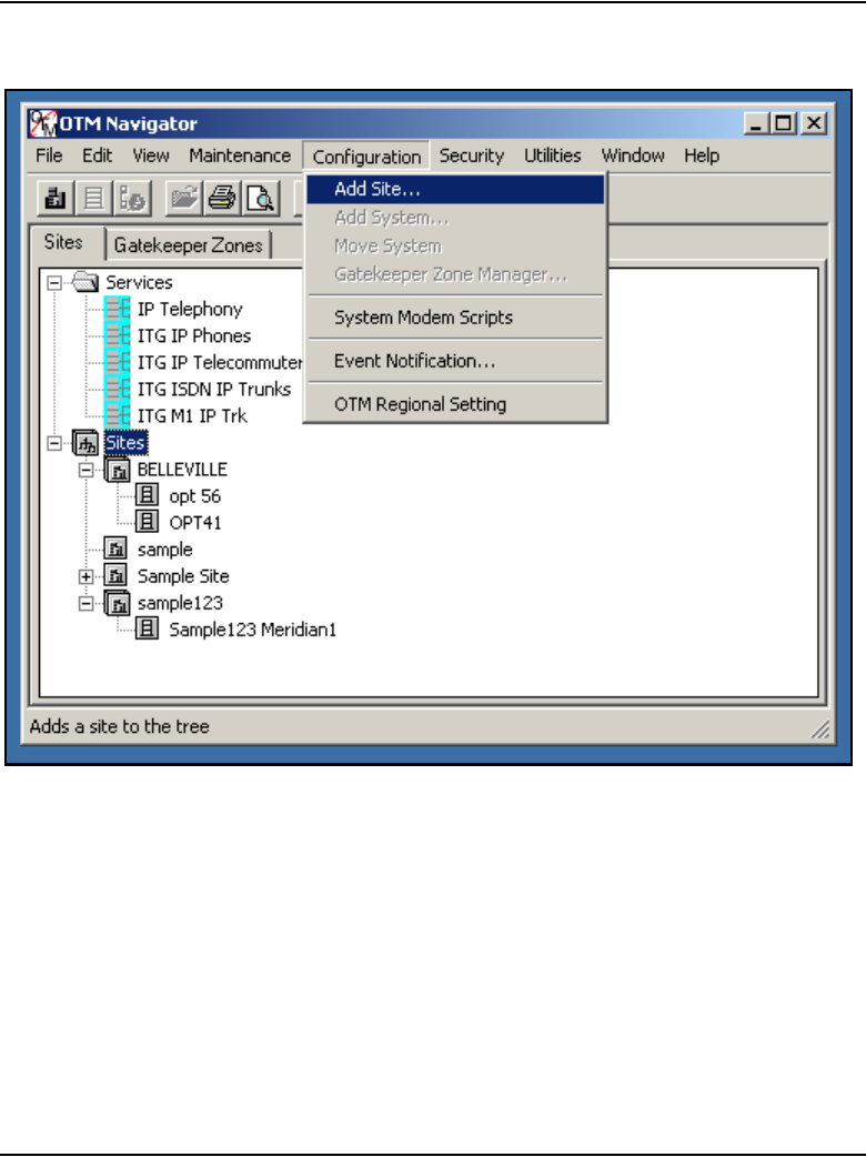
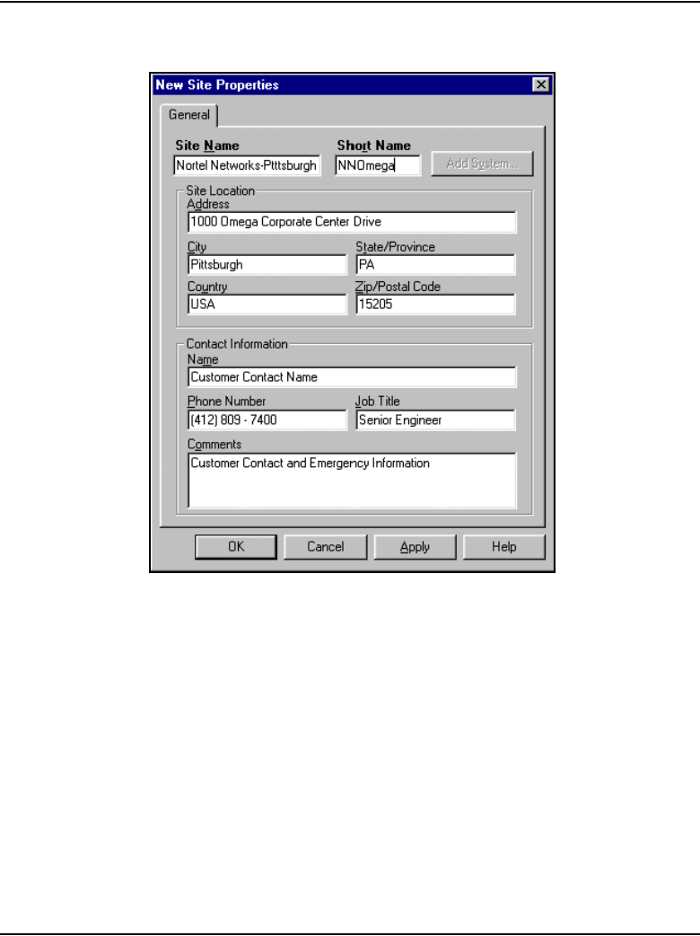
Page 812 of 910 Voice Gateway Media Card maintenance using OTM 2.2
553-3001-365 Standard 4.00 August 2005
Figure 246
New Site Properties
In the New Site Properties window, set the following:
a. Site Name: Add a site named “Retrieve IP Telephony data.”
b. Short Name: Enter a short name for the site.
Under Site Location, add the Address, City, State/Province, Country,
and Zip/Postal Code of the site.
Under Contact Information, add the Name, Phone Number, Job Title,
and any Comments for the site contact person(s).
2Click Apply, and then OK.
3In OTM Navigator, click Configuration > Add System.
The Add System window opens.
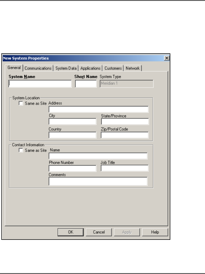
Voice Gateway Media Card maintenance using OTM 2.2 Page 813 of 910
IP Line Description, Installation and Maintenance
4Add a system named “Dummy,” of type “Meridian 1,” under the site
named “Retrieve IP Telephony data.”
Under System Type, click Meridian 1, and then click OK. The New
System Properties window opens. See Figure 247 on page 813.
Figure 247
System Properties – General Tab
5Click the Customers tab. See Figure 248 on page 814.
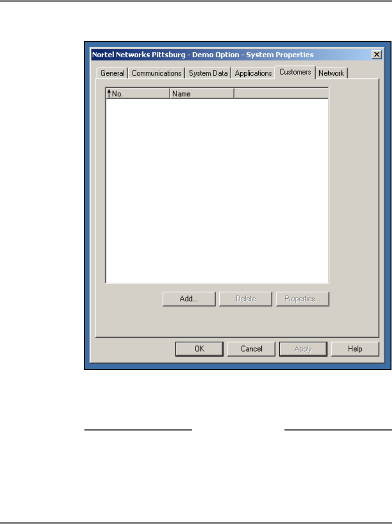
Page 814 of 910 Voice Gateway Media Card maintenance using OTM 2.2
553-3001-365 Standard 4.00 August 2005
Figure 248
System Properties – Customers tab
6Click Add. Add Customer Number “99” on the “dummy” Meridian 1
system.
End of Procedure
Voice Gateway Media Card maintenance using OTM 2.2 Page 815 of 910
IP Line Description, Installation and Maintenance
Retrieve IP Line configuration from the IP Telephony node
Procedure 117 is an optional procedure that can be used in the following
cases:
• when adding an IP Telephony node on OTM by retrieving an existing
node
• when there is a possibility that the IP Telephony node configuration on
the Voice Gateway Media Card differs from the OTM IP Telephony
database (for example, during maintenance and fault isolation
procedures)
• when there are multiple OTM IP Line PCs with multiple instances of the
database (administration)
Use the OTM IP Line Configuration > Synchronize > Retrieve command
to retrieve the IP Line configuration information from the IP Telephony node
as described in Procedure 117.
Procedure 117
Retrieving IP Line configuration data from the IP Telephony node
1In the OTM Navigator, select the Services folder and then double-click
on the IP Telephony icon. The IP Telephony window opens.
2Select Leader 0 or any card from the node.
3In the IP Telephony window, click Configuration > Synchronize >
Retrieve.
The Retrieve Options window opens.
CAUTION
This procedure is not supported for a node that resides
on a CS 1000 system.

Page 816 of 910 Voice Gateway Media Card maintenance using OTM 2.2
553-3001-365 Standard 4.00 August 2005
4Leave the defaulted “Node Properties” option selected, or click the “Card
Properties,” depending upon the situation:
a. Leave the defaulted “Node Properties” in the following situations:
— when the OTM IP Line data is out of date and all OTM IP
Telephony node data will be synchronized with the data from the
Voice Gateway Media Cards on the node
— when adding a node in OTM by retrieving data from an existing
node with more than one card
b. Select “Card Properties” when attempting to isolate a problem with IP
Line configuration on a particular card.
5Select the check boxes for the IP Line configuration data to be retrieved,
depending on the situation:
a. Select Node Properties and Card Properties, if the OTM IP Line
data is out of date and all OTM IP Telephony node data will be
synchronized with the data from the Voice Gateway Media Cards on
the node.
b. Select Card Properties if adding a node on OTM by retrieving data
from an existing node that consists of more than one card.
c. Select any combination of check boxes as indicated by problem
symptoms when attempting to isolate a problem on a particular card.
Use the “dummy” node for this purpose.
6Click the Start retrieve button.
7Monitor the progress of the retrieval under Retrieve control box.
The retrieved Node Properties and Card Properties overwrite the existing
OTM IP Line configuration data for the respective node or card.
End of Procedure

Page 817 of 910
IP Line Description, Installation and Maintenance
848
Convert IP Trunk Cards to Voice Gateway
Media Cards
Contents
This section contains information on the following topics:
Introduction . . . . . . . . . . . . . . . . . . . . . . . . . . . . . . . . . . . . . . . . . . . . . . 818
Before you begin . . . . . . . . . . . . . . . . . . . . . . . . . . . . . . . . . . . . . . . . . . 818
Convert the IP Trunk cards . . . . . . . . . . . . . . . . . . . . . . . . . . . . . . . . . . 819
Obtaining firmware files for the NTVQ01AA/NTVQ01BA Media Card. . . . 820
Obtaining firmware files for the NTVQ01AB/NTVQ01BB Media Card. . . . 826
Obtaining firmware files for the ITG-P 24-port card . . . . . . . . . . . . 832
Add the converted cards to an IP Telephony node . . . . . . . . . . . . . . . . 837
Manually add converted Voice Gateway Media Cards to the existing
IP Telephony node . . . . . . . . . . . . . . . . . . . . . . . . . . . . . . . . . . . . . . 838
Import all converted Voice Gateway Media Cards into a new
IP Telephony node . . . . . . . . . . . . . . . . . . . . . . . . . . . . . . . . . . . . . . 843

Page 818 of 910 Convert IP Trunk Cards to Voice Gateway Media Cards
553-3001-365 Standard 4.00 August 2005
Introduction
Media Card 32-port trunk cards and ITG-P 24-port trunk cards that are no
longer being used as IP Trunk cards can be converted to Voice Gateway
Media Cards running the IP Line 4.5 application.
Post-conversion
After the trunk cards have been converted to run the IP Line 4.5 application,
perform the following actions:
• manually add the converted Voice Gateway Media Cards to an
IP Telephony node
• configure the corresponding Voice Gateway TNs on the Call Server
To perform these actions using OTM 2.2, refer to “Add a Voice Gateway
Media Card to the node” on page 651.
To perform these actions using Element Manager, refer to “Add a Voice
Gateway Media Card to the node” on page 591.
Note: ITG Trunk 2.x nodes that contain Media Cards must be upgraded
to IP Trunk 3.0x and rebooted. This is necessary to enable OTM 2.2 to
transmit the IP Line 4.5 application to the trunk cards that are to be
converted.
Before you begin
Before beginning the conversion procedure, ensure that all IP Trunk 3.0x
cards have received their IP address configuration data from the Active
Leader (Leader 0 or Leader 1) and are functioning in the role of Active
Leader, Backup Leader, or Follower.
Recommendation
Nortel recommends using the OTM 2.2 ITG ISDN trunk service (used to
manage the trunk node) to download the IP Line 4.5 application
loadware to the existing trunk cards.

Convert IP Trunk Cards to Voice Gateway Media Cards Page 819 of 910
IP Line Description, Installation and Maintenance
Convert the IP Trunk cards
Follow the steps in Procedure 118 on page 819 to convert the IP Trunk cards
to Voice Gateway Media Cards.
Procedure 118
Converting IP Trunk card to Voice Gateway Media Cards
1Download the CS 1000 Release 4.5 IP Line 4.5 software (IPL450xx.p2
and IPL450xx.sa) from the Nortel Software Download web page to the
OTM Server. Alternatively, place the Signaling Server Installation CD in
the drive of the OTM Server, or use FTP to obtain the IP Line 4.5 software
from the Signaling Server.
2Use the OTM 2.2 ITG ISDN Trunk service to select the node, or to select
all cards in the node of the same host type (Media Card or ITG-P).
3Right-click and select Configuration > Synchronize > Transmit. Click
the appropriate radio buttons for selected node or selected cards, and for
the card software.
4Click Browse and locate the IP Line 4.5 loadware file for the appropriate
card type (Media Card or ITG-P).
5Click Open > Start Transmit.
Monitor the progress in the Transmit Control window to ensure that the
IP Line 4.5 loadware is transmitted successfully to all selected cards.
6At the Call Server CLI, use the LD 32 DISI command to disable each
IP Trunk card that is being converted.
7In the OTM 2.2 ITG ISDN Trunk service, double-click on each disabled
card that is being converted. Click the Reset button for each card.
8Verify the firmware version of each Media Card and ITG-P 24-port card.
In OTM 2.2 ITG ISDN Trunk service, Telnet to each card and log into the
IPL> shell. Check the firmware version by entering the following:
IPL>firmwareVersionShow
If the Media Card firmware version is not the latest version, follow the
steps in Procedure 119 on page 820 for NTVQ01AA/NTVQ01BA Media
Cards, Procedure 120 on page 826 for NTVQ01AB/NTVQ01BB Media
Cards, or Procedure 121 on page 832 for the ITG-p 24-port cards to
obtain the latest firmware file.

Page 820 of 910 Convert IP Trunk Cards to Voice Gateway Media Cards
553-3001-365 Standard 4.00 August 2005
9If part of the IP trunk node is being retained, then the IP Trunk cards that
are being converted must be deleted from the existing IP Trunk node in
OTM. The IP Trunk node properties must be transmitted from OTM to the
Leader of the IP Trunk node.
If none of the IP Trunk node is being retained, delete the node in OTM 2.2.
End of Procedure
Obtaining firmware files for the NTVQ01AA/NTVQ01BA Media
Card
If the NTVQ01AA/NTVQ01BA Media Card firmware version is less than
version 6.8, follow the steps in Procedure 119.
Procedure 119
Obtain the NTVQ01AA/NTVQ01BA Media Card Release 6.8 firmware
upgrade and instructions
1Access the www.nortel.com web site.
2Select Support & Training > Software Downloads.
The Technical Support window opens. See Figure 249.

Convert IP Trunk Cards to Voice Gateway Media Cards Page 821 of 910
IP Line Description, Installation and Maintenance
Figure 249
Technical Support window
3On the right side of the page, in the Find Products pane, click A–Z.
The Technical Support window with the alphabet links opens.
See Figure 250 on page 822.
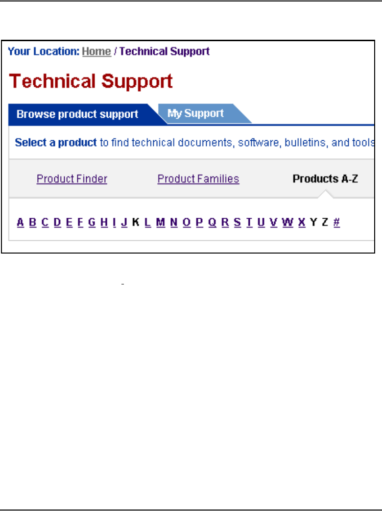

Convert IP Trunk Cards to Voice Gateway Media Cards Page 823 of 910
IP Line Description, Installation and Maintenance
Figure 251
Alphabetic Product Listings window
5Scroll down to IP Line and Voice Gateway Media Cards (VGMC).
See Figure 252.
Figure 252
IP Line and Voice Gateway Media Card (VGMC) listing
6Under IP Line and Voice Gateway Media Cards (VGMC), click
Software.
The IP Line and Voice Gateway Media Cards (VGMC) window opens.
See Figure 253 on page 824.

Page 824 of 910 Convert IP Trunk Cards to Voice Gateway Media Cards
553-3001-365 Standard 4.00 August 2005
Figure 253
IP Line and Voice Gateway Media Cards (VGMC) window
7Scroll down to SMC (Succession Media Card) Release 6.8 Firmware.
See Figure 254.
Figure 254
SMC (Succession Media Card) Release 6.8 Firmware listing and link
8Click SMC (Succession Media Card) Release 6.8 Firmware.
The Software window opens. See Figure 255 on page 825.
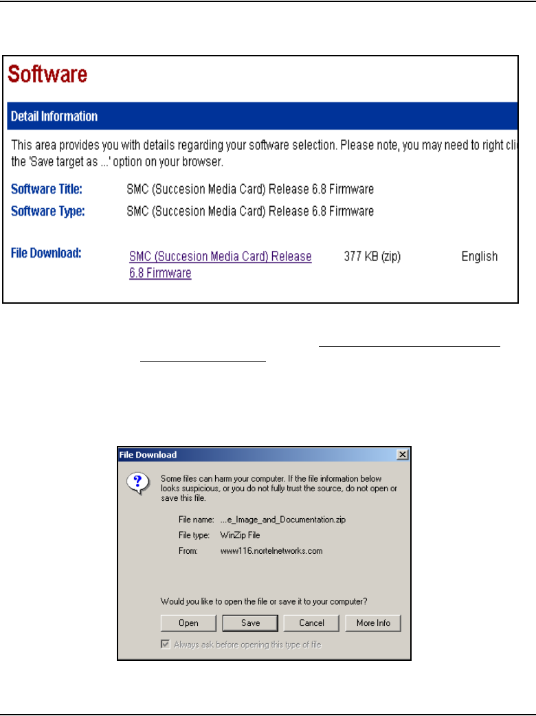
Convert IP Trunk Cards to Voice Gateway Media Cards Page 825 of 910
IP Line Description, Installation and Maintenance
Figure 255
Software window
9In the File Download field, click SMC (Succession Media Card)
Release 6.8 Firmware.
The File Download window opens. See Figure 256.
Figure 256
File Download window

Page 826 of 910 Convert IP Trunk Cards to Voice Gateway Media Cards
553-3001-365 Standard 4.00 August 2005
10 Save the zipped file to the desired location.
11 Return to the IP Line and Voice Gateway Media Cards (VGMC) window.
and scroll down to SMC V6.7 F/W Upgrade Doc 2.1.
12 Click SMC V6.7 F/W Upgrade Doc 2.1.
13 Save the zipped file to the desired location.
14 Unzip the downloaded firmware file and document file.
15 In the document “SMC Firmware Upgrade Procedure”, follow the
instructions in section 5.1 “Firmware upgrade procedures SMC:” to
upgrade the firmware and reboot the Media Card.
16 Disable the IP Trunk cards gracefully, one by one. Upgrade the firmware,
reboot and then enable each card before performing the firmware
upgrade on the next card.
End of Procedure
Obtaining firmware files for the NTVQ01AB/NTVQ01BB Media
Card
If the NTVQ01AB/NTVQ01BB Media Card firmware version is less than
version 8.2, follow the steps in Procedure 119.
Procedure 120
Obtain the NTVQ01AB/NTVQ01BB Media Card Release 8.2 firmware
upgrade and instructions
1Access the www.nortel.com web site.
2Select Support & Training > Software Downloads.
The Technical Support window opens. See Figure 257 on page 827.
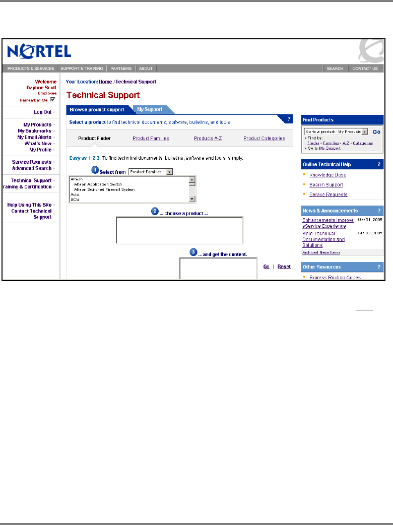
Convert IP Trunk Cards to Voice Gateway Media Cards Page 827 of 910
IP Line Description, Installation and Maintenance
Figure 257
Technical Support window
3On the right side of the page, in the Find Products pane, click A–Z.
The Technical Support window with the alphabet links opens.
See Figure 258 on page 828.

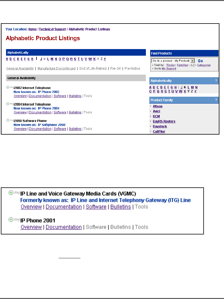
Convert IP Trunk Cards to Voice Gateway Media Cards Page 829 of 910
IP Line Description, Installation and Maintenance
Figure 259
Alphabetic Product Listings window
5Scroll down to IP Line and Voice Gateway Media Cards (VGMC).
See Figure 252.
Figure 260
IP Line and Voice Gateway Media Card (VGMC) listing
6Under IP Line and Voice Gateway Media Cards (VGMC), click
Software.
The IP Line and Voice Gateway Media Cards (VGMC) window opens.
See Figure 261 on page 830.
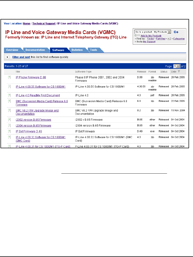
Page 830 of 910 Convert IP Trunk Cards to Voice Gateway Media Cards
553-3001-365 Standard 4.00 August 2005
Figure 261
IP Line and Voice Gateway Media Cards (VGMC) window
7Scroll down to SMC V8.2 F/W Upgrade Image and Documentation.
8Click SMC V8.2 F/W Upgrade Image and Documentation.
The Software window opens. See Figure 262 on page 831.
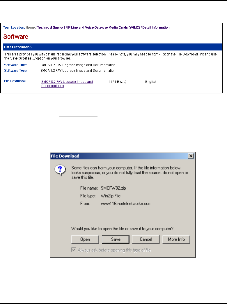
Convert IP Trunk Cards to Voice Gateway Media Cards Page 831 of 910
IP Line Description, Installation and Maintenance
Figure 262
Software window
9In the File Download field, click SMC V8.2 F/W Upgrade Image and
Documentation.
The File Download window opens. See Figure 263.
Figure 263
File Download window
10 Click Save and save the zipped file to the desired location.
11 Unzip the downloaded firmware file and document file.

Page 832 of 910 Convert IP Trunk Cards to Voice Gateway Media Cards
553-3001-365 Standard 4.00 August 2005
12 Follow the instructions in the unzipped document to upgrade the Media
card firmware and reboot the Media Card.
13 Disable the IP Trunk cards gracefully, one by one. Upgrade the firmware,
reboot and then enable each card before performing the firmware
upgrade on the next card.
End of Procedure
Obtaining firmware files for the ITG-P 24-port card
If the ITG-P 24-port card firmware version is less than version 5.7, follow the
steps in Procedure 121.
Procedure 121
Obtain the ITG-P 24-port card Release 5.7 firmware upgrade and
instructions
1Access the www.nortel.com web site.
2Select Support & Training > Software Downloads.
The Technical Support window opens. See Figure 264 on page 833.

Convert IP Trunk Cards to Voice Gateway Media Cards Page 833 of 910
IP Line Description, Installation and Maintenance
Figure 264
Technical Support window
3On the right side of the page, in the Find Products pane, click A–Z.
The Technical Support window with the alphabet links opens.
See Figure 265 on page 834.


Convert IP Trunk Cards to Voice Gateway Media Cards Page 835 of 910
IP Line Description, Installation and Maintenance
Figure 266
Alphabetic Product Listings window
5Scroll down to IP Line and Voice Gateway Media Cards (VGMC).
See Figure 267.
Figure 267
IP Line and Voice Gateway Media Card (VGMC) listing
6Under IP Line and Voice Gateway Media Cards (VGMC), click Software.
The IP Line and Voice Gateway Media Cards (VGMC) window opens.
See Figure 268 on page 836.

Page 836 of 910 Convert IP Trunk Cards to Voice Gateway Media Cards
553-3001-365 Standard 4.00 August 2005
Figure 268
IP Line and Voice Gateway Media Cards (VGMC) window
7Scroll down to ITG-Pentium Release 5.7 Firmware. (It is possible that
the listing may be on the second page of listings.)
8Click ITG-Pentium Release 5.7 Firmware.
9The Software window opens.
See Figure 269 on page 837.
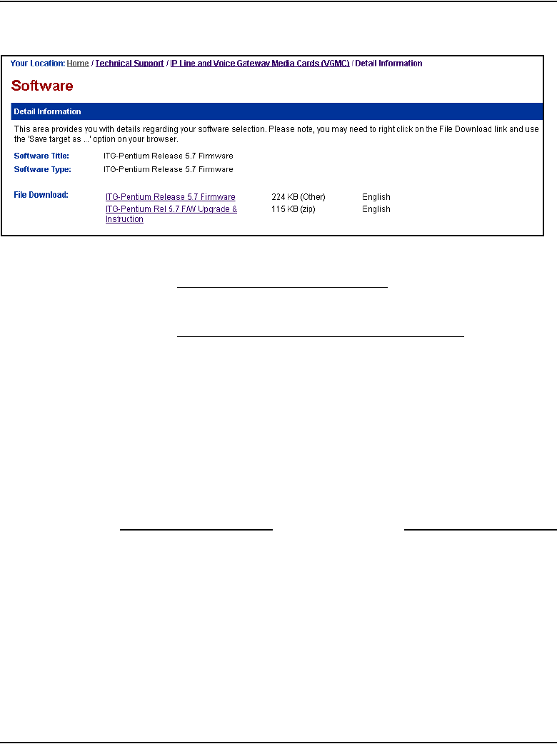
Convert IP Trunk Cards to Voice Gateway Media Cards Page 837 of 910
IP Line Description, Installation and Maintenance
Figure 269
Software window for ITG-P 24-port cards
10 Click ITG-Pentium Release 5.7 Firmware.
11 Save the file to the desired location.
12 Click ITG-Pentium Rel 5.7 F/W Upgrade & Instruction.
13 Save the file to the desired location.
14 Unzip the document file.
15 Follow the procedures in the “ITG-Pentium Rel. 5.7 Firmware Upgrade
and Instruction” document to upgrade the firmware and reboot the ITG-P
card.
Note: Disable the IP Trunk cards, gracefully one by one. Upgrade the
firmware, reboot and then enable each card before performing the
firmware upgrade on the next card.
End of Procedure
Add the converted cards to an IP Telephony node
Before adding the converted cards to an IP Telephony node, ensure the
following:
• the Signaling Server is functioning properly
• the ELAN and TLAN network interfaces are properly configured

Page 838 of 910 Convert IP Trunk Cards to Voice Gateway Media Cards
553-3001-365 Standard 4.00 August 2005
• the Signaling Server is configured as the Leader in the node
• the Call Server software is upgraded to CS 1000 Release 4.5 software
• all unused IP Trunk TNs have been removed from the Call Server
database
• all IP Trunk cards have been converted to Voice Gateway Media Cards
(upgraded to the IP Line 4.5 application)
• a PC is connected to the LAN
Choose one of the following methods:
1“Manually add converted Voice Gateway Media Cards to the existing
IP Telephony node” on page 838.
2“Import all converted Voice Gateway Media Cards into a new
IP Telephony node” on page 843. Use this method if the entire IP Trunk
node has been converted and the converted Voice Gateway Media Cards
do not have to be added to a larger existing node.
Manually add converted Voice Gateway Media Cards to the
existing IP Telephony node
Follow the steps in Procedure 122 to add the converted Voice Gateway Media
Cards to an existing IP Telephony node using Element Manager.
Procedure 122
Adding the converted Voice Gateway Media Cards into an existing
IP Telephony node
1Log in to Element Manager from the web browser by entering the IP
address of the Signaling Server.
2Enter the User ID and password (usually the same as the Call Server
User ID and password).
3In the Element Manager navigator, click IP Telephony > Nodes:
Servers, Media Cards > Configuration.
The Node Configuration window opens.
4Click the Edit button of the node to which the converted cards will be
added as Followers.

Convert IP Trunk Cards to Voice Gateway Media Cards Page 839 of 910
IP Line Description, Installation and Maintenance
The Edit window opens.
5In the Edit window, click the Add button in the Cards field.
The card properties fields are displayed.
6Enter the data for the following fields:
• Management LAN (ELAN) IP address
• Management LAN (ELAN) MAC address
• Voice Lan (TLAN) IP address
• Voice Lan (TLAN) gateway IP address
• Hostname
•Card TN
• Select the card processor type (ITG-P or Media Card)
• H323 ID
• Select the Enable set TPS checkbox
• System name
• System location
• System contact
The following is an example of the card properties data:
Table 111
Example of card properties data (Part 1 of 2)
ELAN IP address 47.11.215.115
ELAN MAC address 00:60:38:bd:fe:80
TLAN IP address 471.11.215.234
TLAN gateway IP address 471.11.215.1
Hostname
Card TN 9
Card Processor Type Media Card
H.323 ID

Page 840 of 910 Convert IP Trunk Cards to Voice Gateway Media Cards
553-3001-365 Standard 4.00 August 2005
7Repeat the previous step for each card that is to be added to the node.
8When the card property data has been entered for all the cards, click the
Save and Transfer button.
This action saves the configuration changes to the Call Server and
transfers the changes to the Signaling Servers and Voice Gateway Media
Cards in the node. The BOOTP and CONFIG.INI files are saved on the
Call Server and transferred to the Signaling Server Leader. The BOOTP
table is updated so that the converted cards can receive their IP address
configuration.
The Transfer Progress window opens.
Note: It might be necessary to press the Reset button on the faceplate of
the converted cards to trigger a new BOOTP request. Do not continue
with this procedure until all converted cards have received their IP
addresses.
9Click the Transfer to Failed Elements button to transfer the bootp.tab
and CONFIG.INI files to the converted cards.
10 Configure the new Voice Gateway TNs on the Call Server using one of
the following methods:
a. Use LD 14 from the Call Server CLI to configure the new Voice
Gateway TNs.
or
b. In the Element Manager navigator, click IP Telephony > Nodes:
Servers, Media Cards > Configuration.
The Node Configuration window opens.
Enable set TPS check mark
System name MGC1
System location BWM system 1
System contact John Smith
Table 111
Example of card properties data (Part 2 of 2)

Convert IP Trunk Cards to Voice Gateway Media Cards Page 841 of 910
IP Line Description, Installation and Maintenance
i. Expand the desired node by clicking the plus sign (+) to the left
of the Node ID.
ii. Click VGW CHANNELS next to the appropriate Voice Gateway
Media Card.
The VGW Channels window opens. See Figure 270 on page 842.
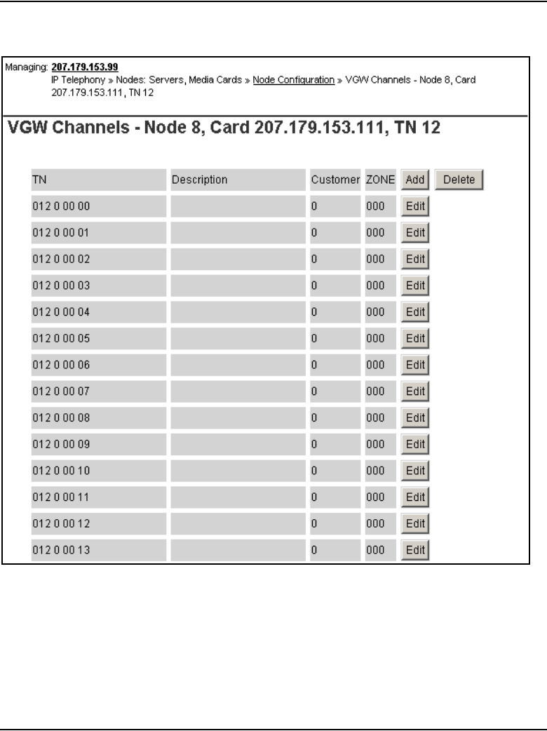
Page 842 of 910 Convert IP Trunk Cards to Voice Gateway Media Cards
553-3001-365 Standard 4.00 August 2005
Figure 270
VGW Channels window
iii. Click Add.
if an Alert Box appears, log into the CLI of the Call Server. Use LD 22
to determine if Package 167 is enabled or restricted by entering 167
as a response to the TYPE prompt.

Convert IP Trunk Cards to Voice Gateway Media Cards Page 843 of 910
IP Line Description, Installation and Maintenance
If Package 167 is restricted, obtain a new keycode to enable GPRI
Package 167.
In LD 73, enter DDB at the TYPE prompt and press <CR> through
the overlay, accepting all the defaults.
End of Procedure
Import all converted Voice Gateway Media Cards into a new
IP Telephony node
Follow the steps in Procedure 123 to import all newly-converted Voice
Gateway Media Cards into a new IP Telephony node using Element Manager.
Procedure 123
Importing all converted Voice Gateway Media Cards into a new IP
Telephony node
1Log into Element Manager from the web browser by entering the
IP address of the Signaling Server.
2Enter the User ID and password (usually the same as the Call Server
User ID and password).
3When logged into Element Manager, click IP Telephony > Nodes:
Servers, Media Cards > Configuration.
The Node Configuration window opens. See Figure 271 on page 844.
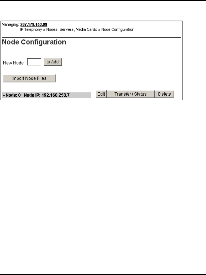

Convert IP Trunk Cards to Voice Gateway Media Cards Page 845 of 910
IP Line Description, Installation and Maintenance
Figure 272
Import Node Files window
5In the box, enter the Leader Management Lan (ELAN) IP address of the
former Leader 0 of the IP Trunk node that has been converted. Click
Import.
The following text is displayed.
The BOOTP.1 and CONFIG1.INI files were retrieved from
Voice Gateway Media Card x.x.x.x.
6As the BOOTP.1 file does not have a node ID, enter the node ID for this
node.
If a Signaling Server has already been installed, the Signaling Server will
be the leader for this node. If IP Phones have been configured to point to
the Signaling Server node ID, use the node ID of that Signaling Server to
create this node. Add the Signaling Server to this node in Step 8.
See Figure 273 on page 846.

Page 846 of 910 Convert IP Trunk Cards to Voice Gateway Media Cards
553-3001-365 Standard 4.00 August 2005
Figure 273
BootP.1 information window
7Enter the node ID.
8Click Continue.
When the new node has been created with the imported data, the
following warning is displayed.
Warning: Call Server address in CONFIG.INI is o.o.o.o.
Please edit the node and update it.
BOOTP.TAB AND CONFIG.INI files for node yyy were
retrieved from Voice Gateway Media Card x.x.x.x. and
stored on Call Server z.z.z.z. The new node will appear
on the Node Summary page (Configuration > IP
Telephony).
9In the Node Configuration window, click the Edit button for the new
node.
The Edit window opens.
10 Expand the LAN section by clicking the plus sign (+) to the left.

Convert IP Trunk Cards to Voice Gateway Media Cards Page 847 of 910
IP Line Description, Installation and Maintenance
11 On the Edit page, in the Management LAN (ELAN) configuration
section, enter the correct IP address of the Call Server:
12 Add the Signaling Server (if it exists and is not already part of a larger IP
Telephony node).
Click Add next to the Signaling Server section.
13 Add any additional Voice Gateway Media Cards.
Click Add next to the Cards section.
14 After all required fields for the card properties have been entered, click
Submit and Transfer.
This action saves the configuration changes to the Call Server and
transfers the changes to the Signaling Servers and Voice Gateway Media
Cards in the node.
The Transfer Progress window is displayed.
The BOOTP.1 and CONFIG.INI file are saved on the Call Server and
transferred to the Signaling Server Leader. The BOOTP table is updated
so that the converted cards can receive their IP addresses.
Note: It might be necessary to press the Reset button on the faceplate of
the converted cards to trigger a new BOOTP request. Do not continue
with this procedure until all converted cards have received their
IP addresses.
15 Configure the new Voice Gateway TNs on the Call Server using one of
the following methods:
a. Use LD 14 from the Call Server CLI to configure the new Voice
Gateway TNs.
or
b. In the Element Manager navigator, click IP Telephony > Nodes:
Servers, Media Cards > Configuration.
The Node Configuration window opens.
i. Expand the node by clicking the plus sign (+) to the left of the
Node ID.
ii. Click the appropriate Voice Gateway Media Card.
iii. Click VGW CHANNELS next to the appropriate Voice Gateway
Media Card.

Page 848 of 910 Convert IP Trunk Cards to Voice Gateway Media Cards
553-3001-365 Standard 4.00 August 2005
The VGW Channels window opens. See Figure 270 on
page 842
iv. if an Alert Box appears, log into the CLI of the Call Server. In LD
22, enter 167 as a response to the TYPE prompt to determine if
Package 167 is enabled or restricted.
If it is restricted, obtain a new keycode to enable GPRI Package
167.
In LD 73, enter DDB at the TYPE prompt.:
Press <CR> through the overlay, accepting all the defaults.
16 If no Signaling Server is added to the imported node, Telnet to the former
IP Trunk Leader 0 card and use the clearLeader command to remove the
Leader Flag from Leader 0.
End of Procedure

Page 849 of 910
IP Line Description, Installation and Maintenance
856
Appendix A: NAT router requirements
for NAT Traversal feature
Contents
This section contains information on the following topics:
Description . . . . . . . . . . . . . . . . . . . . . . . . . . . . . . . . . . . . . . . . . . . . . . 849
Requirements. . . . . . . . . . . . . . . . . . . . . . . . . . . . . . . . . . . . . . . . . . . . . 850
Cone NAT . . . . . . . . . . . . . . . . . . . . . . . . . . . . . . . . . . . . . . . . . . . . 850
Time-out configuration. . . . . . . . . . . . . . . . . . . . . . . . . . . . . . . . . . . 851
Hairpinning. . . . . . . . . . . . . . . . . . . . . . . . . . . . . . . . . . . . . . . . . . . . 851
Unidirectional packet flow . . . . . . . . . . . . . . . . . . . . . . . . . . . . . . . . 852
Firmware versions . . . . . . . . . . . . . . . . . . . . . . . . . . . . . . . . . . . . . . 853
Natcheck output. . . . . . . . . . . . . . . . . . . . . . . . . . . . . . . . . . . . . . . . . . . 854
Description
This appendix describes the requirements of a Network Address Translation
(NAT) router to enable it to support the NAT Traversal feature.
For a NAT device to work correctly between an IP Phone and the CS 1000
system, the following requirements must be met:
1A cone NAT must be used.
2The Private-to-Public mapping should have a long time-out configured.
3If multiple IP Phones will be supported behind the same NAT router,
hairpinning must be supported.

Page 850 of 910 Appendix A: NAT router requirements for NAT Traversal feature
553-3001-365 Standard 4.00 August 2005
4The Private-to-Public mapping created by a NAT router must be kept
alive by packets in only one direction (standard in most NAT routers).
5The IP Phone must be running the correct minimum firmware version
(not a NAT device requirement, but still important).
Most of the issues encountered can be confirmed using either an IP Phone
behind the NAT device or a PC running the third-party tool “natcheck”.
Note: Nortel is not affiliated in any manner with the natcheck tool, and
therefore is not liable or responsible for any problems that may be
encountered with this tool.
The natcheck tool can be downloaded at no cost from the Internet at:
http://midcom-p2p.sourceforge.net/. The natcheck tool runs in Windows on a
PC connected to the internet through a NAT router.
Requirements
Cone NAT
The NAT Traversal feature cannot work unless the NAT device has a cone
NAT implemented.
Confirm using natcheck
Run the natcheck program. Look for the following message:
UDP consistent translation: YES (GOOD for peer-to-peer)
If YES is displayed, then the NAT router uses a cone NAT.

Appendix A: NAT router requirements for NAT Traversal feature Page 851 of 910
IP Line Description, Installation and Maintenance
Confirm using IP Phone
The NAT router uses a cone NAT if no error message is displayed when the
IP Phone registers to the system. The NAT device does not use a cone NAT
if the IP Phone behind it displays the following error message:
NAT Error! ITG3053
Please try upgrading firmware on the NAT device or
replacing it with a different NAT device that has a cone
NAT implemented.
Time-out configuration
Confirm using natcheck
Time-out configuration cannot be performed using natcheck.
Confirm using IP Phone
If the IP Phone connection times out and the IP Phone reboots, use LD 117 to
lower the NAT Keep Alive Timer value on the Call Server. The reboots could
indicate that the NAT device’s address/port mapping is being cleared because
there is no message traffic from the IP Phone. By lowering the NAT Keep
Alive Timer value in the Call Server, keep-alive messages are sent more
frequently to keep the mapping “alive”.
>ld 117
->chg nkt 20
If lowering the NAT Keep Alive Timer value to the minimum value of 20
seconds doesn’t stop the time-outs, try replacing the NAT device.
Hairpinning
Hairpinning occurs when an IP Phone behind a NAT router can send packets
to the Public IP address and Port of another IP Phone connected to the same
NAT router. Determine if hairpinning is supported on the NAT router.
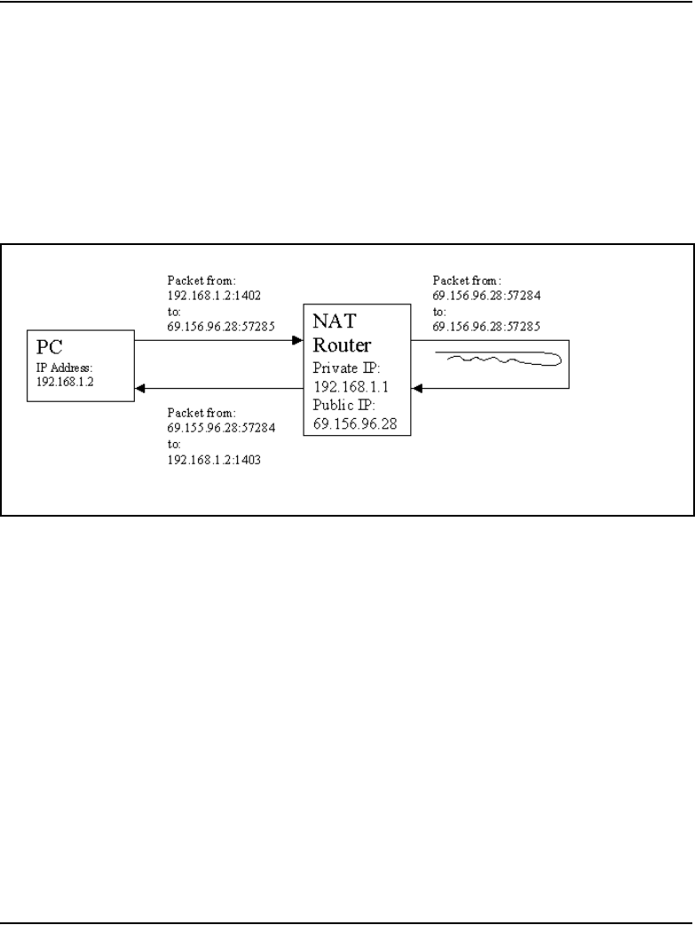
Page 852 of 910 Appendix A: NAT router requirements for NAT Traversal feature
553-3001-365 Standard 4.00 August 2005
Confirm using natcheck
Run the natcheck program. Look for the message:
UDP loopback translation: YES (GOOD for peer-to-peer)
If this messages prints, then a two-way speech path should be available
between two IP Phones behind the NAT device. See Figure 274.
Figure 274
Speech path
Confirm using IP Phone
Connect two IP Phones to the same NAT device and call from one phone to
the other. Confirm that a two-way speech path is achieved during the call.
Unidirectional packet flow
Confirm using natcheck
The natcheck tool cannot be used to determine if the private-to-public
mapping created by the NAT device is being kept alive by a unidirectional
packet flow.

Appendix A: NAT router requirements for NAT Traversal feature Page 853 of 910
IP Line Description, Installation and Maintenance
Confirm using IP Phone
If an IP Phone behind a NAT device has a two-way speech path immediately
after being registered, and continues to have a two-way speech path 2 – 30
minutes later, then the NAT device’s address/port mapping is being kept alive
by the packets. If a one-way speech path occurs after this time period, ensure
that the IP Phone has the latest CS 1000 Release 4.5 firmware version. If the
IP Phone has the latest firmware, then the problem lies with the NAT device.
Try replacing the NAT device with a different model.
If the one-way speech path problem is fixed after rebooting the IP Phone, it
is likely that the NAT device does not meet the requirement of unidirectional
packet flow. As well, ensure that the firmware on the IP Phone has the latest
CS 1000 Release 4.5 firmware version (older firmware versions can be a
possible source of the one-way speech path problem).
Firmware versions
The IP Phone must have the correct minimum firmware version loaded.
Confirm using natcheck
The natcheck tool cannot be used to determine the IP Phone firmware version.
Confirm using IP Phone
On the IP Phone, go to the Services > Telephone Options > Set Info menu
and scroll down to the FW Version menu item. The minimum firmware
versions (based on the vintage of the IP Phone) that support the NAT
Traversal feature are:
• IP Phone 2002 and IP Phone 2004: xxxxB64
• Phase II IP Phone 2002 and IP Phone 2004: xxxxD41
• IP Softphone 2050: xxxx375
Earlier firmware versions do not correctly support the NAT Traversal feature.

Page 854 of 910 Appendix A: NAT router requirements for NAT Traversal feature
553-3001-365 Standard 4.00 August 2005
Natcheck output
A NAT router using CONE NAT will have output similar to the following.
D:\natcheck>natcheck -v
server 1: pdos.lcs.mit.edu at 18.26.4.9:9856
server 2: tears.lcs.mit.edu at 18.26.4.77:9856
server 3: sure.lcs.mit.edu at 18.26.4.29:9856
Local TCP port: 1400
Local UDP port: 1401
Request 1 of 20...
Connection to server 2 complete
Server 1 reports my UDP address as 69.156.96.28:57283
Server 2 reports my UDP address as 69.156.96.28:57283
Server 3 reports my UDP address as 69.156.96.28:57283
Connection to server 1 complete
Server 1 reports my TCP address as 69.156.96.28:57281
Connection from 18.26.4.29:9856
Server 3 reports my TCP address as 69.156.96.28:57281
Request 2 of 20...
Loopback packet from 69.156.96.28 port 57285
Request 3 of 20...
Loopback packet from 69.156.96.28 port 57285
Request 4 of 20...
Loopback packet from 69.156.96.28 port 57285
Request 5 of 20...
Loopback packet from 69.156.96.28 port 57285
Server 2 reports my TCP address as 69.156.96.28:57281
Initiated TCP server 3 connection
Initiated TCP loopback connection
Connection from 69.156.96.28:57289
Loopback received
Request 6 of 20...
Loopback packet from 69.156.96.28 port 57285
Request 7 of 20...
Loopback packet from 69.156.96.28 port 57285
Request 8 of 20...
Loopback packet from 69.156.96.28 port 57285
Request 9 of 20...
Loopback packet from 69.156.96.28 port 57285
Request 10 of 20...
Loopback packet from 69.156.96.28 port 57285
Request 11 of 20...
Loopback packet from 69.156.96.28 port 57285
Request 12 of 20...
Loopback packet from 69.156.96.28 port 57285
Request 13 of 20...
Loopback packet from 69.156.96.28 port 57285

Appendix A: NAT router requirements for NAT Traversal feature Page 855 of 910
IP Line Description, Installation and Maintenance
Request 14 of 20...
Loopback packet from 69.156.96.28 port 57285
Request 15 of 20...
Loopback packet from 69.156.96.28 port 57285
Request 16 of 20...
Loopback packet from 69.156.96.28 port 57285
Request 17 of 20...
Loopback packet from 69.156.96.28 port 57285
Request 18 of 20...
Loopback packet from 69.156.96.28 port 57285
Request 19 of 20...
Loopback packet from 69.156.96.28 port 57285
Request 20 of 20...
Loopback packet from 69.156.96.28 port 57285
TCP RESULTS:
TCP consistent translation: YES (GOOD for peer-to-peer)
TCP simultaneous open: YES (GOOD for peer-to-peer)
TCP loopback translation: YES (GOOD for peer-to-peer)
TCP unsolicited connections filtered: NO (BAD for security)
UDP RESULTS:
UDP consistent translation: YES (GOOD for peer-to-peer)
UDP loopback translation: YES (GOOD for peer-to-peer)
UDP unsolicited messages filtered: NO (BAD for security)
The important information is highlighted in red.
In order for the NAT router to support the NAT Traversal feature, natcheck
must print the following to the screen:
UDP consistent translation: YES (GOOD for peer-to-peer)
YES indicates that Cone NAT is being used. NO indicates that Symmetric
NAT is present. Symmetric NAT is not supported.
Note: Near the beginning of the printout, the PUBLIC port seen by
various servers is printed out. In this case, all three servers receive the
packets from the same PUBLIC port of 57283. This Private-to-Public
port mapping is seen in Figure 275 on page 856.
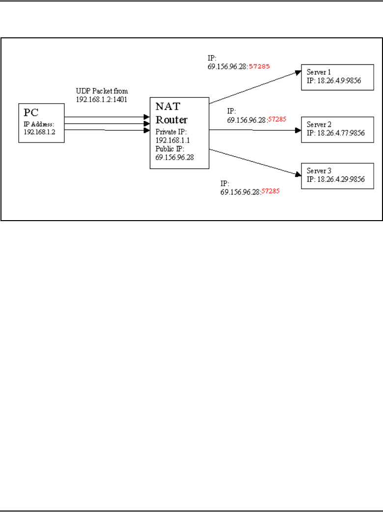
Page 856 of 910 Appendix A: NAT router requirements for NAT Traversal feature
553-3001-365 Standard 4.00 August 2005
Figure 275
Private-to-Public port mapping
Since all three servers see the same PUBLIC port, the NAT router is using
Cone NAT.

Page 857 of 910
IP Line Description, Installation and Maintenance
870
Appendix B: I/O, maintenance, and
extender cable description
Contents
This section contains information on the following topics:
Introduction . . . . . . . . . . . . . . . . . . . . . . . . . . . . . . . . . . . . . . . . . . . . . . 857
NTMF94EA I/O cable. . . . . . . . . . . . . . . . . . . . . . . . . . . . . . . . . . . . . . 858
Connector pin assignments . . . . . . . . . . . . . . . . . . . . . . . . . . . . . . . . . . 860
Prevent ground loops on connection to external customer LAN equipment 863
NTAG81CA maintenance cable description. . . . . . . . . . . . . . . . . . . . . 864
NTAG81BA maintenance extender cable. . . . . . . . . . . . . . . . . . . . . . . 865
Replace the NT8D81BA cable with the NT8D1AA cable and install the
NTCW84JW special IPE filter. . . . . . . . . . . . . . . . . . . . . . . . . . . . . . . . . . . . . . . . 866
Tools list . . . . . . . . . . . . . . . . . . . . . . . . . . . . . . . . . . . . . . . . . . . . . . 868
Remove the NT8D81BA cable. . . . . . . . . . . . . . . . . . . . . . . . . . . . . 868
Install the NTCW84JA filter and NT8D81AA cable . . . . . . . . . . . . 869
Introduction
This appendix describes the NTMF94EA, NTAG81CA, and NTAG81BA
cables and explains how to replace the NT8D81BA backplane ribbon cable
and install the NTCW84JA filter, if required.

Page 858 of 910 Appendix B: I/O, maintenance, and extender cable description
553-3001-365 Standard 4.00 August 2005
NTMF94EA I/O cable
The NTMF94EA cable provides the ELAN and TLAN network interfaces
from the Voice Gateway Media Card to the customer’s network equipment.
This cable also has one DB9 serial port that provides serial connection
between the card and the customer PC or TTY. See Figure 276 on page 859.
It is important to use the mounting screw provided to secure the top of the
NTMF94EA cable 25-pair Amphenol connector to the system. The screw ties
the LAN cable shield to the Meridian 1/CS 1000 frame ground for EMC
compliance.
The NTMF94EA cable provides a factory-installed, shielded, RJ-45-to-RJ-45
coupler at the end of both the ELAN and the TLAN network interfaces. An
unshielded coupler is provided to prevent ground loops (if required). Refer to
“Prevent ground loops on connection to external customer LAN equipment”
on page 863, to determine if the unshielded coupler should be used. Both ends
of the RJ-45 ports of the cables are labeled to distinguish the TLAN network
interface and the ELAN network interface. The ports provide the connection
point to the customer’s ELAN and TLAN equipment. Use shielded CAT5
cable to connect to the customer’s equipment.
To improve EMC performance, use standard cable ties to bundle all LAN
cables as they route out of the system.
Note: To avoid damage to CAT5 cable, do not overtighten cable ties.
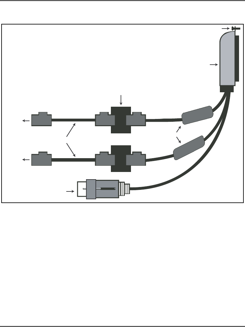
Appendix B: I/O, maintenance, and extender cable description Page 859 of 910
IP Line Description, Installation and Maintenance
Figure 276
NTMF94EA ELAN, TLAN and RS-232 serial maintenance I/O cable
Mounting Screw
Shielded 25-pair
Amphenol Connector
Shielded RJ-45
Mating Coupler
Shielded RJ-45 Cable
Ferrite
9 Pin D-Sub
Female
To Switch
To Switch
553-ITG0006

Page 860 of 910 Appendix B: I/O, maintenance, and extender cable description
553-3001-365 Standard 4.00 August 2005
Connector pin assignments
Table 112 shows the I/O connector pin designations for the Voice Gateway
Media Card.
Table 112
Voice Gateway Media Card I/O Panel Pinout (Part 1 of 2)
Pin
Normal
Assignment
ITG
Assignment Pin
Normal
Assignment
ITG
Assignment
2R1 Not Used 26 T0 Not Used
3R2 Not Used 27 T1 Not Used
4R3 Not Used 28 T2 Not Used
5R4 Not Used 29 T3 Not Used
6R5 AGND 30 T4 AGND
7R6 Not Used 31 T5 Not Used
8R7 Not Used 32 T6 Not Used
9R8 Not Used 33 T7 Not Used
10 R9 AGND 34 T8 AGND
11 R10 PGT0 35 T9 PGT1
12 R11 PGT2 36 T10 PGT3
13 R12 PGT4 37 T11 PGT5
14 R13 PGT6 38 T12 PGT7
15 R14 PGT8 39 T13 PGT9
16 R15 PGT10 40 T14 PGT11
17 R16 SGNDA 41 T15 BDCDA-
18 R17 BSINA- 42 T16 BSOUTA-
19 R18 BDTRA- 43 T17 SGND
20 R19 BDSRA- 44 T18 BRTSA-

Appendix B: I/O, maintenance, and extender cable description Page 861 of 910
IP Line Description, Installation and Maintenance
21 R20 BCTSA- 45 T19 BSINB-
22 R21 BSOUTB- 46 T20 BDCDB-
23 R22 BDTRB- 47 T21 BDSRB-
24 R23 DI+ 48 T22 DI-
25 no connect DO+ 49 T23 DO-
2R1 no connect 50 no connect no connect
Table 112
Voice Gateway Media Card I/O Panel Pinout (Part 2 of 2)
Pin
Normal
Assignment
ITG
Assignment Pin
Normal
Assignment
ITG
Assignment

Page 862 of 910 Appendix B: I/O, maintenance, and extender cable description
553-3001-365 Standard 4.00 August 2005
Table 113
NTMF94EA cable pin description
I/O Panel: P1 Signal Name P2, P3,P4 Color
P1-21 BSOUTB- P2-2 RED
P1-22 BDTRB- P2-4 GREEN
SGRND P2-5 BROWN
P1-45 BSINB- P2-3 BLUE
P1-46 BDCDB- P2-1 ORANGE
P1-47 BDSRB- P2-6 YELLOW
P1-25 SHLD GRND
P1-50 SHLD GRND
P1-18 RXDB+ P4-3 GREEN/WHITE
P1-19 TXDB+ P4-1 ORANGE/WHITE
P1-43 RXDB- P4-6 WHITE/GREEN
P1-44 TXDB- P4-2 WHITE/ORANGE
P1-23 RX+ P3-3 GREEN/WHITE
P1-24 TX+ P3-1 ORANGE/WHITE
P1-48 RX- P3-6 WHITE/GREEN
P1-49 TX- P3-2 WHITE/ORANGE
P1-25 SHLD GRND BARE
P1-50 SHLD GRND BARE
Appendix B: I/O, maintenance, and extender cable description Page 863 of 910
IP Line Description, Installation and Maintenance
Prevent ground loops on connection to external customer
LAN equipment
The shielded RJ-45 coupler is the connection point for the customer’s
shielded CAT5 LAN cable to the hub, switch, or router supporting the TLAN
and ELAN subnets. Use shielded CAT5 RJ-45 cable to connect to the
customer’s TLAN/ELAN equipment. Follow the steps in Procedure 124 to
prevent ground loops when connecting to external customer LAN equipment.
Follow the steps in Procedure 124 to prevent ground loops.
Procedure 124
Preventing ground loops
1Connect the customer-provided shielded CAT5 LAN cable to the external
LAN equipment. Ensure that the external LAN equipment is powered-up.
2Use an ohmmeter to measure resistance to ground between the free end
of the shielded RJ-45 cable and the building ground.
The ohmmeter must measure Open to ground before plugging it into the
shielded RJ-45 coupler on the end of the NTMF94EA.
If the ohmmeter does not measure Open, install the unshielded RJ-45
coupler (provided) on the end of the NTMF94EA to prevent ground loops
to external LAN equipment.
End of Procedure
WARNING
The serial maintenance ports on the faceplate connector
and the DB-9 female connector of the NTMF9DA cable
assembly are identical. Do not connect a serial device to
both access points simultaneously. This results in
incorrect and unpredictable operation of the Voice
Gateway Media Card.

Page 864 of 910 Appendix B: I/O, maintenance, and extender cable description
553-3001-365 Standard 4.00 August 2005
NTAG81CA maintenance cable description
The NTAG81CA maintenance cable is connected between the 9-pin D-type
RS-232 input on a standard PC and the MAINT connector on the NT8R17AB
faceplate or through the I/O cable serial port. See Figure 277.
Figure 277
NTAG81CA Maintenance cable
The NTAG91CA maintenance cable pin description is outlined in Table 114.
Table 114
NTAG81CA maintenance cable pin description
Signals
(MIX Side)
8-pin Mini-DIN
(MIX Side)
Male
9-pin D-Sub
(PC Side)
Female
Signals
(PC Side)
DTRB- 16DSR-
SOUTB- 22SIN-
SINB- 33SOUT-
GND 4 5 GND
SINA- 5nc nc
CTSA- 6nc nc
SOUTA- 7nc nc
DTRA- 8nc nc
DIN-8
DB-9 Female
553-ITG0007

Appendix B: I/O, maintenance, and extender cable description Page 865 of 910
IP Line Description, Installation and Maintenance
NTAG81BA maintenance extender cable
The NTAG81BA maintenance extender (3 m) cable connects the
NTAG81CA cable to a PC or terminal. It has a 9-pin D-type connector at both
ends; one male and one female. See Table 115. The cable can also be used to
extend the serial port presented by the NTMF94EA I/O panel cable. The
extender cable is shown in Figure 278.
Figure 278
NTAG81BA Maintenance Extender cable
Table 115
NTAG81BA Maintenance cable pin description
9-pin D-Sub (Male) 9-pin D-Sub (Female)
11
22
33
44
55
66
77
88
99
DB-9 female
DB-9 male
553-9245

Page 866 of 910 Appendix B: I/O, maintenance, and extender cable description
553-3001-365 Standard 4.00 August 2005
Replace the NT8D81BA cable with the NT8D1AA cable
and install the NTCW84JW special IPE filter
This procedure explains how to replace the NT8D81BA cable with the
NT8D81AA cable and how to install the NTCW84JA special IPE filter in the
IPE module.
Cables are designated by the letter of the I/O panel cutout, such as A, B, and
C, where the 50-pin cable connector is attached. Each cable has three 20-pin
connectors (16 positions are used), designated 1, 2, and 3, that attach to the
backplane. Using the designations described, the backplane ends of the first
cable are referred to as A-1, A-2, and A-3. The locations of the cable
connectors on the backplane are designated by the slot number (L0 through
L9 for NT8D11, L0 through L15 for NT8D37) and the shroud row (1, 2, and
3). Using these designations, the slot positions in the first slot are referred to
as L0-1, L0-2, and L0-3.
In NT8D37BA and NT8D37EC (and later vintage) IPE Modules, all 16 IPE
card slots support 24-pair cable connections. Table 116: “NT8D37 cable
connections” on page 867 shows the cable connections from the backplane to
the inside of the I/O panel.

Appendix B: I/O, maintenance, and extender cable description Page 867 of 910
IP Line Description, Installation and Maintenance
Figure 279 on page 868 shows the designations for the backplane end of the
cables, the backplane slot designations for the cable connections, and the
associated network segments for the backplane slots.
Table 116
NT8D37 cable connections
Backplane slots – shroud rows I/O panel/cable designation
L0–1, 2, 3
L1–1, 2, 3
L2–1, 2, 3
L3–1, 2, 3
L4–1, 2, 3
L5–1, 2, 3
L6–1, 2, 3
L7–1, 2, 3
L8–1, 2, 3
L9–1, 2, 3
L10–1, 2, 3
L11–1, 2, 3
L12–1, 2, 3
L13–1, 2, 3
L14–1, 2, 3
L15–1, 2, 3
A
B
C
D
E
F
G
H
K
L
M
N
R
S
T
U
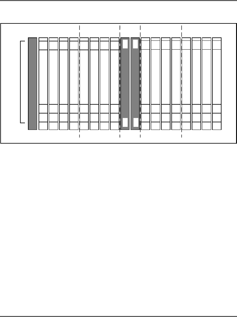
Page 868 of 910 Appendix B: I/O, maintenance, and extender cable description
553-3001-365 Standard 4.00 August 2005
Figure 279
Backplane slot designations
Tools list
The following tools are required to perform this procedure.
• Ty-wrap cutter
• Ty-wraps
• Needle nose pliers
• Slotted screwdriver
Remove the NT8D81BA cable
Follow the steps in Procedure 125 on page 869 to remove the NT8D81BA
cable.
Segment 0
L15 L14 L13 L12 L11 L10 L9 L8 L7 L6 L5 L4 L3 L2 L1 L0
A-1
B-3
C-2
E-3
F-2
E-1 B-1
A-2
A-3
B-2
C-1
C-3
E-2
F-1
F-3
1
2
3
Shroud row
553-5391
L-1R-1S-1T-1 M-1
Segment 1Segment 2Segment 3
SL0
SL1
SL2
SL3
L16
G-1
G-3
G-2L-2
L-3
M-2
M-3
R-1
R-1
K-1
K-2
K-3
S-2
S-3
T-2
T-3
D-1
D-2
D-3
H-1
H-2
H-3
N-1
N-2
N-3
U-1
U-2
U-3

Appendix B: I/O, maintenance, and extender cable description Page 869 of 910
IP Line Description, Installation and Maintenance
Procedure 125
Removing an NT8D81BA cable
1Identify the I/O panel and backplane designation that corresponds to the
LEFT slot of the pair of card slots, viewed from the front, in which the
ITG ISL Trunk card is installed.
2Disconnect the filter from the I/O panel using a screwdriver and needle
nose pliers. Retain the fasteners.
3Power down the IPE shelf.
4Remove the IPE module I/O safety panel.
5To remove the ribbon cables from the IPE backplane, apply gentle
pressure on the tab on the right side of the shroud while pulling on the
connector until it pulls free from the shroud.
Remove connector 1 first, then remove connectors 2 and 3.
6Discard the NT8D81BA cable.
End of Procedure
Install the NTCW84JA filter and NT8D81AA cable
Follow the steps in Procedure 126 to install the NTCW84JA filter and
NT8D81AA cable.
Procedure 126
Installing an NTCW84JA filter and NT8D81AA cable
1Install the NTCW84JA special IPE filter connector in the vacant I/O panel
slot using retained hardware.
2Install the NT8D81AA ribbon cable connectors in the IPE module
backplane shroud. Be sure to install the connector so the label is facing
right with the arrow pointing up and the connector is fully engaged into the
shroud:
a. Install connector 1, (labeled UP1^) into backplane shroud 1.
b. Install connector 2, (labeled UP2^) into backplane shroud 2.
c. Install connector 3, (labeled UP3^) into backplane shroud 3.

Page 870 of 910 Appendix B: I/O, maintenance, and extender cable description
553-3001-365 Standard 4.00 August 2005
3Dress the ribbon cables back individually inside the rear of IPE module
and restore the original arrangement. Start with the cables that are going
to be underneath.
4Attach the NTCW84JA special IPE filter to the NT8D81AA 50-pin
connector using bail clips.
5Restore power to the IPE module.
6Replace the I/O safety panel.
End of Procedure

Page 871 of 910
IP Line Description, Installation and Maintenance
892
Appendix C: RM356 Modem Router
Contents
This section contains information on the following topics:
Introduction . . . . . . . . . . . . . . . . . . . . . . . . . . . . . . . . . . . . . . . . . . . . . . 871
RM356 Modem Router security features . . . . . . . . . . . . . . . . . . . . . . . 872
Install the RM356 Modem Router . . . . . . . . . . . . . . . . . . . . . . . . . . . . 874
Configure the RM356 Modem Router from the manager menu. . . . . . 875
RM356 Modem Router manager menu description . . . . . . . . . . . . . . . 883
Introduction
Management and support of the IP Line network depend on IP networking
protocols including SNMP, FTP, and Telnet. Install a Modem Router on the
Meridian 1/CS 1000 site LAN subnet (called the Embedded LAN or ELAN
subnet as opposed to the customer's data network subnet) in order to provide
remote support access for IP Line and other IP-enabled Nortel products.
WARNING
Nortel strongly recommends that the RM356 Modem
Router be installed for management and support.

Page 872 of 910 Appendix C: RM356 Modem Router
553-3001-365 Standard 4.00 August 2005
The Netgear RM356 Modem Router integrates the functions of a V.90
modem, a PPP remote access server, an IP router, and a 4-port 10BaseT
Ethernet hub, and provides a range of security features configured to comply
with the customer's data network security policy. Do not install a Modem
Router on the ELAN subnet without the explicit approval of the customer's IP
network manager. The RM356 Modem Router is not secure unless it is
configured correctly according to the customer's network security policy and
practices.
Figure 280 on page 873 shows an example of a remote network.
RM356 Modem Router security features
The security features of the RM356 Modem Router include:
• Password Authentication Protocol (PAP) for dial-in PPP connection
• RM356 manager password
• CLID for dial-in user authentication (requires CO line with Calling Line
ID)
• Callback for dial-in user authentication
• Dial-in user profiles
• Static IP routing
• IP packet filtering
• Idle timeout disconnect for dial-in PPP connection
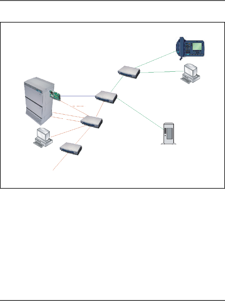
Appendix C: RM356 Modem Router Page 873 of 910
IP Line Description, Installation and Maintenance
Figure 280
Remote support using Netgear RM356 Modem Router
TLAN subnet
Enterprise IP Network
PC
DHCP Server
Switch
Hub
Netgear RM 356
Modem Router
ELAN
PSTN
Netgear RM 356
Modem Router
OTM
Core 1
Core 0
IP Phone 2004
Router
Core 0
subnet

Page 874 of 910 Appendix C: RM356 Modem Router
553-3001-365 Standard 4.00 August 2005
Install the RM356 Modem Router
Follow the steps in Procedure 127 to install the RM356 Modem Router.
Procedure 127
Installing the RM356 Modem Router
1Place the Modem Router at a conveniently visible and physically secure
location near an AC power outlet, an analog telephone line, and a
10BaseT Ethernet cable.
Up to four hosts or hubs can be connected to the integrated 10BaseT hub
in the rear of the RM356 Modem Router.
2Use shielded CAT5 10BaseT Ethernet cables to connect the Modem
Router to the ELAN switch. Other IP-enabled Nortel products on the
ELAN can be connected to the RM356 Modem Router, including the
Meridian 1, CS 1000M, CS 1000, a local Optivity Telephone Manager
(OTM) 2.2 PC, Symposium Call Center Server, and CallPilot.
Note: The up-link connection to an additional ELAN hub or optional
gateway on the customer’s enterprise network requires either a
cross-over 10BaseT Ethernet cable or a special up-link port on the
10BaseT hub to which the RM356 is connected.
3Connect the Modem Router to the AC power source. The power LED
lights. After several seconds, the test LED flashes slowly four times, then
stays off.
For each of the four 10BaseT ports on the integrated hub, there is a
link/data LED that lights steadily to indicate a good link connection (if a
cable is connected to a host or hub) or is flashing to indicate data received
on the LAN.
4Connect the RJ-45 plug end of the local manager cable to the RS-232
Manager port RJ-45 jack on the rear of the Modem Router.
5Connect the other end of the manager cable to an RS-232 terminal or PC
COM port configured for the following communication parameters:
• 9600 baud
• 8 bits
• no parity bit
• 1 stop bit

Appendix C: RM356 Modem Router Page 875 of 910
IP Line Description, Installation and Maintenance
6The local maintenance cable connects directly to Data Terminal
Equipment (DTE).
Note: The analog telephone line must be either a CO line or a PBX
extension with a Direct Inward Dialing (DID) number, whichever complies
with the customer's network security policy.
End of Procedure
Configure the RM356 Modem Router from the
manager menu
This procedure can be performed from a terminal or PC connected to the local
RS-232 manager port on the rear of the Modem Router. Alternatively, the
manager menu can be accessed by Telnet after the IP addressing and routing
have been set up initially from the local manager port.
Use the following keys in the RM356 manager menu:
• the arrow keys to navigate
• the spacebar key to toggle pre-defined configuration values for a field
• the Enter key to save data changes to ROM and exit the current menu
• the Esc key to exit the current menu without saving changes
• enter menu selection number when prompted to display a sub-menu,
configuration form, or command prompts
Follow the steps in Procedure 128 to configure the RM356 Modem Router.
Procedure 128
Configuring the RM356 Modem Router
1Press the Enter key from the terminal or manager menu.
The Enter Password: prompt is displayed for 10 seconds.
2Enter the default RM356 manager password 1234.

Page 876 of 910 Appendix C: RM356 Modem Router
553-3001-365 Standard 4.00 August 2005
The RM356 Main Menu is displayed. See page 883 for a complete view
of the RM356 Modem Router menus.
RM356 Main Menu
3At the Enter Menu Selection Number: prompt, enter menu selection
number 1 to access the General Setup under Getting Started.
The Menu 1 - General Setup sub-menu is displayed.
Menu 1 - General Setup
System Name= Room_304_RCH_Training_Center
Location= Sherman Ave., Richardson, TX
Contact Person's Name= John Smith, 972 555-1212
Press ENTER to Confirm or ESC to Cancel:
4Under General Setup, type in the System Name (19 characters, no
spaces), Location, and Contact Person's Name for the system site.
Use the up and down arrow keys to move the cursor to the prompt Press
ENTER to Confirm or ESC to Cancel: at the bottom of the menu. Press
Enter to confirm and save data to ROM.
5Enter menu selection number 2 to access the MODEM Setup under the
Getting Started section.
Getting Started
1. General Setup
2. MODEM Setup
3. Ethernet Setup
4. Internet Access Setup
Advanced Management
21. Filter Set
Configuration
23. System Password
24. System Maintenance
Advanced Applications
11. Remote Node Setup
12. Static Routing Setup
13. Default Dial-in Setup
14. Dial-in User Setup
99. Exit
Enter Menu Selection Number:

Appendix C: RM356 Modem Router Page 877 of 910
IP Line Description, Installation and Maintenance
The Menu 2 - Modem Setup sub-menu is displayed.
Menu 2 - MODEM Setup
Modem Name= MODEM
Active= Yes
Direction= Incoming
Phone Number=
Advanced Setup= No
Press ENTER to Confirm or ESC to Cancel:
6Use the arrow keys to navigate and space bar to toggle values. Type in
Modem Name. Set Active = Yes and Direction = Incoming. Type in the
Modem Router's Phone Number for reference.
7Press Enter to confirm and save data to ROM.
8Enter menu selection number 3, to access Ethernet Set under the Getting
Started section.
The Menu 3: Ethernet Setup sub-menu is displayed.
Menu 3 - Ethernet Setup
1. General Setup
2. TCP/IP and DHCP Setup
Enter Menu Selection Number:
9Enter menu selection 2, under Ethernet Setup.

Page 878 of 910 Appendix C: RM356 Modem Router
553-3001-365 Standard 4.00 August 2005
The Menu 3.2 - TCP/IP and DHCP Ethernet Setup is displayed.
Menu 3.2 - TCP/IP and DHCP Ethernet Setup
DHCP Setup:
DHCP= None
Client IP Pool Starting Address= N/A
Size of Client IP Pool= N/A
Primary DNS Server= N/A
Secondary DNS Server= N/A
TCP/IP Setup:
IP Address= 47.177.16.254
IP Subnet Mask= 255.255.255.0
RIP Direction= None
Version= RIP-2B
Press ENTER to Confirm or ESC to Cancel:
Press Space Bar to Toggle.
10 Under DHCP Setup, toggle DHCP = None using the space bar.
11 Under TCP/IP Setup, type in the IP Address and the IP Subnet Mask for
the Modem Router's Ethernet interface on the ELAN.
12 Toggle RIP Direction = None.
13 Press Enter to confirm and save data to ROM, then press Esc to return
to the RM356 Main Menu.
14 Enter menu selection number 12, under the Advanced Applications
section.
The Menu 12 - Static Route Setup sub-menu is displayed.
Menu 12 - Static Route Setup
1. DefaultGW
2. ________
3. ________
4. ________
Enter Menu Selection Number:

Appendix C: RM356 Modem Router Page 879 of 910
IP Line Description, Installation and Maintenance
Note 1: If firewall security is properly configured in the customer's
Management GW router, and if the Modem Router is allowed access over
the customer’s enterprise network to other IP Telephony nodes on remote
ELAN subnets, define a default network route pointing to the
Management GW IP address on the local ELAN subnet. Alternatively,
define up to four different static network routes or host routes in the
Modem Router to limit routing access from the Modem Router to the
customer’s enterprise network.
Note 2: To prevent access from the Modem Router to the TLAN subnet
through the Management GW router on the ELAN subnet, disable RIP by
setting RIP Direction = None, and remove all static routes or disable a
particular static route by setting Active = No.
15 Enter menu selection number 1 to edit the first static route.
Menu 12.1 - Edit IP Static Route is displayed.
Menu 12.1 - Edit IP Static Route
Route #: 1
Route Name= DefaultGW
Active= Yes
Destination IP Address= 0.0.0.0
IP Subnet Mask= 0.0.0.0
Gateway IP Address= 47.177.16.1
Metric= 2
Private= No
Press ENTER to Confirm or ESC to Cancel:
16 Type in a descriptive Route Name using no spaces, for example,
DefaultGW. Toggle Active = Yes/No for security purposes.
The Gateway IP Address is the Management GW IP address on the
ELAN where the Modem Router is connected.
17 Press Enter to confirm and save data to ROM, then press Esc to return
from the sub-menu to the RM356 Main Menu.

Page 880 of 910 Appendix C: RM356 Modem Router
553-3001-365 Standard 4.00 August 2005
18 Enter menu selection number 13, under the Advanced Applications
section.
The Menu 13 - Default Dial-in Setup sub-menu is displayed.
Menu 13 - Default Dial-in Setup
Press ENTER to Confirm or ESC to Cancel:
Press Space Bar to Toggle.
19 Under Telco Options, toggle CLIDAuthen = None/Preferred/ Required.
CLID requires a CO line subscribed for CLID service where available.
• Preferred means some dial-in user profiles require CLID, but others
do not.
• Required means no dial-in call is connected unless CLID is provided
and user profiles require CLID for authentication.
20 Under PPP Options, toggle Recv Authen = PAP.
Windows 9x Dial-up Networking (DUN) is not compatible with CHAP/PAP
or CHAP on the Modem Router. Calls are disconnected after a few
minutes.
21 Toggle Compression= No.
Windows 9x DUN is not compatible with software compression on the
Modem Router. Calls are randomly disconnected.
22 Toggle Mutual Authen= No.
Telco Options:
CLID Authen= None
IP Address Supplied By:
Dial-in User= No
IP Pool= Yes
IP Start Addr= 47.177.16.253
PPP Options:
Recv Authen= PAP
Compression= No
Mutual Authen= No
PAP Login= N/A
PAP Password= N/A
Session Options:
Input Filter Sets=
Output Filter Sets=
Idle Timeout= 1200
Callback Budget Management:
Allocated Budget(min)=
Period(hr)=

Appendix C: RM356 Modem Router Page 881 of 910
IP Line Description, Installation and Maintenance
23 Under IP Address Supplied By, toggle Dial-in User= No and
IP Pool = Yes.
24 For IP Start Addr =, type in the ELAN IP address that will be assigned to
the Dial-up Networking (DUN) PPP client on the remote OTM 2.2 PC.
Note: The remote OTM PC receives this ELAN IP address when DUN
makes a dial-in PPP connection to the Modem Router. As long as DUN
remains connected to the Modem Router, IP applications on the remote
OTM PC function as if the PC were located on the customer's ELAN.
25 Under Session Options, configure Input Filter Sets = and Output Filter
Sets = according to the customer's IP network security policy and
practices.
The default setting; however, is no Filter Sets.
26 Set Idle Timeout = 1200.
1200 seconds provides 20 minutes idle timeout disconnect for remote
support purposes.
27 Press Enter to confirm and save data to ROM and then press Esc to
return from the sub-menu to the main menu.
28 Enter menu selection number 14, under the Advanced Applications
section.
The Menu 14 - Dial-in User Setup is displayed.
Menu 14 - Dial-in User Setup
1. itgadmin
2. ________
3. ________
4. ________
5. ________
6. ________
7. ________
8. ________
Enter Menu Selection Number:
Note: Up to eight dial-in user profiles can be defined according to the
customer's network security policy.
29 Enter menu selection 1 to edit the first dial-in user profile.

Page 882 of 910 Appendix C: RM356 Modem Router
553-3001-365 Standard 4.00 August 2005
Menu 14.1 - Edit Dial-in User is displayed.
Menu 14.1 - Edit Dial-in User
User Name= itgadmin
Active= Yes
Password= ********
Callback= No
Phone # Supplied by Caller= N/A
Callback Phone #= N/A
Rem CLID=
Idle Timeout= 500
Press ENTER to Confirm or ESC to Cancel:
30 Type in the User Name, such as itgadmin.
31 Toggle Active = Yes/No for security purposes.
32 Type in a Password for PAP.
The DUN client on the remote OTM 2.2 PC must provide the user name
and password defined here when dialing up the Modem Router.
33 Set Callback = Yes/No according to the customer's network security
policy and practices.
Nortel Customer Technical Services (CTS) does not currently accept
Callback security calls from the Modem Router.
34 Set Rem CLID = to the PSTN Calling Number that is displayed when the
remote OTM 2.2 PC dials up the Modem Router, if CLID authentication is
required for the user profile.
CLID depends on providing a C.O. line subscribed for CLID service for the
Modem Router's telephone line connection.
35 Set Idle Timeout = 1200, where 1200 seconds provides 20 minutes idle
timeout disconnect for Nortel remote support purposes.
36 Press Enter to confirm and save data to ROM, then press Esc to return
from the sub-menu to the RM356 Main Menu.
37 Enter menu selection number 23, under the Advanced Management
section of the RM356 Main Menu.

Appendix C: RM356 Modem Router Page 883 of 910
IP Line Description, Installation and Maintenance
Menu 23 - System Password is displayed.
Menu 23 – System Password
Old Password= ?
New Password= ?
Retype to confirm= ?
Enter here to CONFIRM or ESC to CANCEL:
38 Type in the Old Password.
39 Navigate down and type a New Password.
40 Navigate down to Retype to confirm and then retype the new password.
41 Press Enter to save the save the changes.
Note: Never leave the RM356 system manager password defaulted to
1234 after the Modem Router has been installed and configured on the
ELAN. The Modem Router's security features are ineffective if the
manager password is not changed on a regular basis according to good
network security practices.
End of Procedure
RM356 Modem Router manager menu description
This section displays the various menus of the RM356 Modem Router:
RM356 Main Menu
Getting Started Advanced Management
1. General Setup 21. Filter Set Configuration
2. MODEM Setup
3. Ethernet Setup 23. System Password
4. Internet Access Setup 24. System Maintenance
Advanced Applications
11. Remote Node Setup
12. Static Routing Setup
13. Default Dial-in Setup
14. Dial-in User Setup 99. Exit

Page 884 of 910 Appendix C: RM356 Modem Router
553-3001-365 Standard 4.00 August 2005
Enter Menu Selection Number:
Menu 1 - General Setup
System Name= Room_304_RCH_Training_Center
Location= Sherman Ave., Richardson, TX
Contact Person's Name= John Smith, 972 555-1212
Press ENTER to Confirm or ESC to Cancel:
Menu 2 - MODEM Setup
Modem Name= MODEM
Active= Yes
Direction= Incoming
Phone Number=
Advanced Setup= No
Press ENTER to Confirm or ESC to Cancel:
Menu 3 - Ethernet Setup
1. General Setup
2. TCP/IP and DHCP Setup
Enter Menu Selection Number:
Menu 3.1 - General Ethernet Setup
Input Filter Sets= 2
Output Filter Sets=
Press ENTER to Confirm or ESC to Cancel:
Menu 3.2 - TCP/IP and DHCP Ethernet Setup

Appendix C: RM356 Modem Router Page 885 of 910
IP Line Description, Installation and Maintenance
DHCP Setup:
DHCP= None
Client IP Pool Starting Address= N/A
Size of Client IP Pool= N/A
Primary DNS Server= N/A
Secondary DNS Server= N/A
TCP/IP Setup:
IP Address= 47.177.16.254
IP Subnet Mask= 255.255.255.0
RIP Direction= None
Version= RIP-2B
Press ENTER to Confirm or ESC to Cancel:
Press Space Bar to Toggle.
Menu 12 - Static Route Setup
1. DefaultGW
2. ________
3. ________
4. ________
Enter Menu Selection Number:
Menu 12.1 - Edit IP Static Route
Route #: 1
Route Name= DefaultGW
Active= Yes
Destination IP Address= 0.0.0.0
IP Subnet Mask= 0.0.0.0
Gateway IP Address= 47.177.16.1
Metric= 2

Page 886 of 910 Appendix C: RM356 Modem Router
553-3001-365 Standard 4.00 August 2005
Private= No
Press ENTER to Confirm or ESC to Cancel:
Menu 13 - Default Dial-in Setup
Telco Options: IP Address Supplied By:
CLID Authen= None Dial-in User= No
IP Pool= Yes
PPP Options: IP Start Addr= 47.177.16.253
Recv Authen= PAP
Compression= No Session Options:
Mutual Authen= No Input Filter Sets=
PAP Login= N/A Output Filter Sets=
PAP Password= N/A Idle Timeout= 1200
Callback Budget Management:
Allocated Budget(min)=
Period(hr)=
Press ENTER to Confirm or ESC to Cancel:
Press Space Bar to Toggle.
Menu 14 - Dial-in User Setup
1. itgadmin
2. ________
3. ________
4. ________
5. ________
6. ________
7. ________
8. ________
Enter Menu Selection Number:

Appendix C: RM356 Modem Router Page 887 of 910
IP Line Description, Installation and Maintenance
Menu 14.1 - Edit Dial-in User
User Name= itgadmin
Active= Yes
Password= ********
Callback= No
Phone # Supplied by Caller= N/A
Callback Phone #= N/A
Rem CLID=
Idle Timeout= 500
Press ENTER to Confirm or ESC to Cancel:
Menu 21 - Filter Set Configuration
Filter Filter
Set # Comments Set # Comments
------ ----------------- ------ -----------------
1 NetBEUI_WAN 7 _______________
2 NetBEUI_LAN 8 _______________
3 _______________ 9 _______________
4 _______________ 10 _______________
5 _______________ 11 _______________
6 _______________ 12 _______________
Enter Filter Set Number to Configure= 0
Edit Comments=
Press ENTER to Confirm or ESC to Cancel:

Page 888 of 910 Appendix C: RM356 Modem Router
553-3001-365 Standard 4.00 August 2005
Menu 21.1 - Filter Rules Summary
# A Type Filter Rules M m n
- - ---- ----------------------------------------------- - - -
1 Y IP Pr=17, SA=0.0.0.0, SP=137, DA=0.0.0.0 N D N
2 Y IP Pr=17, SA=0.0.0.0, SP=138, DA=0.0.0.0 N D N
3 Y IP Pr=17, SA=0.0.0.0, SP=139, DA=0.0.0.0 N D N
4 Y IP Pr=6, SA=0.0.0.0, SP=137, DA=0.0.0.0 N D N
5 Y IP Pr=6, SA=0.0.0.0, SP=138, DA=0.0.0.0 N D N
6 Y IP Pr=6, SA=0.0.0.0, SP=139, DA=0.0.0.0 N D F
Enter Filter Rule Number (1-6) to Configure:
Menu 23 - System Password
Old Password= ?
New Password= ?
Retype to confirm= ?
Enter here to CONFIRM or ESC to CANCEL:
Menu 24 - System Maintenance
1. System Status
2. Terminal Baud Rate
3. Log and Trace
4. Diagnostic
5. Backup Configuration
6. Restore Configuration
7. Software Update
8. Command Interpreter Mode
9. Call Control
Enter Menu Selection Number:

Appendix C: RM356 Modem Router Page 889 of 910
IP Line Description, Installation and Maintenance
Menu 24.1 -- System Maintenance - Status
Port Status Speed TXPkts RXPkts Errs Tx B/s Rx B/s Up Time
1 Idle 0Kbps 16206 12790 0 0 0 0:00:00
Total Outcall Time: 0:00:00
Ethernet: Name: Room_304_RCH_Traini
Status: 10M/Half Duplex RAS S/W Version: V2.13 | 9/25/98
TX Pkts: 135579 Ethernet Address:00:a0:c5:e0:5b:a6
RX Pkts: 662866
Collisions: 49
LAN Packet Which Triggered Last Call:
Press Command:
COMMANDS: 1-Drop Port 1 9-Reset Counters ESC-Exit
Menu 24.2 -- System Maintenance - Change Terminal Baud Rate
Terminal Baud Rate: 9600
Press ENTER to Confirm or ESC to Cancel:
Press Space Bar to Toggle.
Menu 24.3 == System Maintenance - Log and Trace
1. View Error Log
2. Syslog and Accounting
Please enter selection:
0 179754 PINI INFO SMT Session End
1 179761 PP09 INFO Password pass
2 179761 PINI INFO SMT Session Begin

Page 890 of 910 Appendix C: RM356 Modem Router
553-3001-365 Standard 4.00 August 2005
3 179763 PINI INFO SMT Session End
4 179772 PP09 INFO Password pass
5 179772 PINI INFO SMT Session Begin
6 179775 PINI INFO SMT Session End
7 179783 PP09 INFO Password pass
8 179783 PINI INFO SMT Session Begin
9 179788 PINI INFO SMT Session End
10 179796 PP09 INFO Password pass
11 179796 PINI INFO SMT Session Begin
12 179798 PINI INFO SMT Session End
13 179812 PP09 INFO Password pass
14 179812 PINI INFO SMT Session Begin
15 179815 PINI INFO SMT Session End
16 179830 PP09 INFO Password pass
17 179830 PINI INFO SMT Session Begin
18 179834 PINI INFO SMT Session End
Menu 24.3.2 -- System Maintenance - Syslog and Accounting
Syslog:
Active= No
Syslog IP Address= ?
Log Facility= Local 1
Press ENTER to Confirm or ESC to Cancel:
Press Space Bar to Toggle.
Menu 24.4 - System Maintenance - Diagnostic
MODEM System
1. Drop MODEM 21. Reboot System
2. Reset MODEM 22. Command Mode
3. Manual Call

Appendix C: RM356 Modem Router Page 891 of 910
IP Line Description, Installation and Maintenance
4. Redirect to MODEM
TCP/IP
11. Internet Setup Test
12. Ping Host
Enter Menu Selection Number:
Manual Call Remote Node= N/A
Host IP Address= N/A
Menu 24.7 -- System Maintenance - Upload Firmware
1. Load RAS Code
2. Load ROM File
Enter Menu Selection Number: 1

Page 892 of 910 Appendix C: RM356 Modem Router
553-3001-365 Standard 4.00 August 2005

Page 893 of 910
IP Line Description, Installation and Maintenance
900
Appendix D: Product integrity
Contents
This section contains information on the following topics:
Introduction . . . . . . . . . . . . . . . . . . . . . . . . . . . . . . . . . . . . . . . . . . . . . . 893
Reliability . . . . . . . . . . . . . . . . . . . . . . . . . . . . . . . . . . . . . . . . . . . . . . . 893
Mean Time Between Failures (MTBF) . . . . . . . . . . . . . . . . . . . . . . 894
Voice Gateway Media Card power consumption. . . . . . . . . . . . . . . 894
Environmental specifications . . . . . . . . . . . . . . . . . . . . . . . . . . . . . . . . 894
Temperature-related conditions . . . . . . . . . . . . . . . . . . . . . . . . . . . . 895
Electrical regulatory standards . . . . . . . . . . . . . . . . . . . . . . . . . . . . . . . 896
Safety . . . . . . . . . . . . . . . . . . . . . . . . . . . . . . . . . . . . . . . . . . . . . . . . 896
Electro-Magnetic Containment . . . . . . . . . . . . . . . . . . . . . . . . . . . . 897
Introduction
This chapter presents information about the Voice Gateway Media Card’s
reliability, environmental specifications, and electrical regulatory standards.
Reliability
Reliability is measured by the Mean Time Between Failures (MTBF).

Page 894 of 910 Appendix D: Product integrity
553-3001-365 Standard 4.00 August 2005
Mean Time Between Failures (MTBF)
The Mean Time Between Failure (MTBF) is 46 years for Voice Gateway
Media Cards. Failures per 106 hours of operation are 2.483, based on
40 degrees C (140 degrees F).
Voice Gateway Media Card power consumption
The worst case current drawn by the Voice Gateway Media Cards from each
Backplane voltage supply is provided in Table 117 on page 894:
Environmental specifications
Table 118 shows the environmental specifications of the Voice Gateway
Media Card. The Voice Gateway Media Card provides external interface
protection to –52 V DC, but does not provide lightning or hazardous voltage
protection.
Table 117
Voice Gateway Media Card power consumption
Card Type Power Consumption
ITG-Pentium 24-port
card
+ 15 volt = 19.3 watts => 0.640 amps
+5 volt = 10.5 watts => 2.1 amps
Media Card + 15 volt = 6 watts => 0.2 amps
+5 volt = 7.25 watts => 1.45amps
Table 118
Voice Gateway Media Card – environmental specifications
Parameter Specifications
Operating temperature 0° to +60° C (+32 to +140° F), ambient
Operating humidity 5 to 95% RH (non-condensing)
Storage temperature –40° to +70° C (–40° to +158° F)

Appendix D: Product integrity Page 895 of 910
IP Line Description, Installation and Maintenance
Measurements of performance in regards to temperature and shock were
made under test conditions as described in Table 119.
Temperature-related conditions
Refer to Table 119 for a display of acceptable temperature and humidity
ranges for the Voice Gateway Media Card.
Table 119
Voice Gateway Media Card – environmental specifications
Specification Minimum Maximum
Normal Operation
Recommended 15° C 30° C
Relative humidity 20% 55% (non-
condensing)
Absolute 10 ° C 45° C
Relative humidity 20% to 80%
(non-condensing)
Short Term
(less than 72 hr)
–40° C 70° C
Rate of change Less than 1° C for every 3 minutes
Storage
Recommended –20° C 60° C
Relative humidity 5% 95%
(non-condensing)
–40° C to 70° C, non-condensing
Temperature Shock
In 3 minutes –40° C 25° C
In 3 minutes 70° C 25° C
–40° to 70° C, non-condensing

Page 896 of 910 Appendix D: Product integrity
553-3001-365 Standard 4.00 August 2005
Electrical regulatory standards
Table 120, Table 121 on page 898, and Table 122 on page 898 list the safety
and Electro-magnetic Compatibility regulatory standards (by geographic
region) for the Voice Gateway Media Card.
Specifications for the Voice Gateway Media Card meet or exceed the
standards listed in these regulations.
Safety
Table 120 provides a list of safety regulations met by the Voice Gateway
Media Card, along with the type of regulation and the country/region covered
by each regulation.
Table 120
Safety regulations
Regulation Identifier Regulatory Agency
UL 1459 Safety, United States, CALA
CSA 22.2 225 Safety, Canada
EN 41003 Safety, International Telecom
EN 60950/IEC 950 Safety, International
BAKOM SR 784.103.12/4.1/1 EMC/Safety (Switzerland)
AS3260, TS001 – TS004, TS006 Safety/Network (Australia)
JATE Safety/Network (Japan)

Appendix D: Product integrity Page 897 of 910
IP Line Description, Installation and Maintenance
Electro-Magnetic Containment
Electro-Magnetic Containment (EMC) compliance requirements depend on
the regulations in effect for the country where the Meridian 1 or CS 1000
system is located. CISPR 22 Class B defines more stringent EMC limits than
CISPR 22 Class A requirements (that is, equipment that meets CISPR 22
Class B exceeds CISPR 22 Class A requirements and can be used globally).
The ITG-P 24-port line card and the Media Cards are approved for CISPR 22
Class A (and FCC Part 15 Class A) limits and approved to CISPR 22 Class B
limits with the following configurations:
• ITG-P 24-port line card
— For Small Systems, there is no limit to the number of ITG-P 24-port
line cards that can be installed on a shelf to meet CISPR 22 Class A
(and FCC Part 15 Class A) limits. However, to meet CISPR 22 Class
B limits, there is a limit of two cards for each shelf.
— For Large Systems, there is no limit to the number of ITG-P 24-port
line cards that can be installed on a shelf to meet CISPR 22 Class A
(and FCC Part 15 Class A) limits and CISPR 22 Class B limits.
•Media Card
— For Small Systems, there is no limit to the number of Media Cards
that can be installed on a shelf to meet CISPR 22 Class A (and FCC
Part 15 Class A) limits and CISPR 22 Class B limits. If the Media
Cards are installed in a shelf that already has ITG-P 24-port line
cards, then the ITG-P 24-port line card’s EMC requirements
supersedes the Media Card EMC requirements.
— For Large Systems, there is no limit to the number of Media Cards
that can be installed on a shelf to meet CISPR 22 Class A (and FCC
Part 15 Class A) limits. To meet CISPR 22 Class B limits, there is a
limit of ten Media Cards that can be installed on one shelf. If the
Media Cards are to be installed in a shelf that already has ITG-P
24-port line cards, then the ITG-P 24-port line card’s EMC
requirements supersedes the Media Card’s EMC requirements.

Page 898 of 910 Appendix D: Product integrity
553-3001-365 Standard 4.00 August 2005
Table 121 lists Electro-magnetic emissions regulations met by the Voice
Gateway Media Card, along with the country’s standard that lists each
regulation.
Table 122 lists Electro-magnetic immunity regulations met by the Voice
Gateway Media Card, along with the country’s standard that lists each
regulation.
Table 121
Electro-Magnetic emissions
Regulation Identifier Regulatory Agency
FCC part 15 Class A United States Radiated Emissions
CSA C108.8 Canada Radiated Emissions
EN50081-1 European Community Generic
Emission Standard
EN55022/CISPR 22 CLASS B Radiated Emissions (Basic Std.)
BAKOM SR 784.103.12/4.1/1 EMC/Safety (Switzerland)
SS-447-20-22 Sweden EMC standard
AS/NZS 3548 EMC (Australia/New Zealand)
NFC 98020 France EMC standard
Table 122
Electro-Magnetic immunity (Part 1 of 2)
Regulation Identifier Regulatory Agency
CISPR 22 Sec. 20 Class B I/O conducted noise
IEC 801-2 (level 4) ESD (Basic Standard)
IEC 801-3 (level 2) Radiated Immunity (Basic Standard)
IEC 801-4 (level 3) Fast transient/Burst Immunity (Basic
Standard)
IEC 801-5 (level 4, preliminary) Surge Immunity (Basic Standard)

Appendix D: Product integrity Page 899 of 910
IP Line Description, Installation and Maintenance
IEC 801-6 (preliminary) Conducted Disturbances (Basic
Standard)
BAKOM SR 784.103.12/4.1/1 EMC/Safety (Switzerland)
SS-447-20-22 Sweden EMC standard
AS/NZS 3548 EMC (Australia/New Zealand)
NFC 98020 France EMC standard
Table 122
Electro-Magnetic immunity (Part 2 of 2)
Regulation Identifier Regulatory Agency

Page 900 of 910 Appendix D: Product integrity
553-3001-365 Standard 4.00 August 2005

Page 901 of 910
IP Line Description, Installation and Maintenance
902
Appendix E: Subnet Mask Conversion
from CIDR to Dotted Decimal Format
Introduction
Subnet masks are expressed in Classless InterDomain Routing (CIDR)
format, appended to the IP address, such as 10.1.1.1/20. The subnet mask
must be converted from CIDR format to dotted decimal format in order to
configure IP addresses.
The CIDR format expresses the subnet mask as the number of bits counting
from the most significant bit of the first IP address field. A complete IP
address consists of 32 bits. Therefore, a typical CIDR format subnet mask is
in the range from /9 to /30. Each decimal number field in the dotted decimal
format has a value from 0 to 255, where decimal 255 represents binary 1111
1111.
Follow the steps in Procedure 129 on page 902 to convert a subnet mask from
CIDR format to dotted decimal format.

Page 902 of 910 Appendix E: Subnet Mask Conversion from CIDR to Dotted Decimal Format
553-3001-365 Standard 4.00 August 2005
Procedure 129
Converting a subnet mask from CIDR format to dotted decimal format
1Divide the CIDR format value by 8. The quotient (the number of times that
eight divides into the CIDR format value) equals the number of dotted
decimal fields containing 255.
In the example above, the subnet mask is expressed as /20. Twenty
divided by eight equals a quotient of two, with a remainder of four.
Therefore, the first two fields of the subnet mask in dotted decimal format
are 255.255.
2If there is a remainder, refer to Table 123 to obtain the dotted decimal
value for the field following the last field containing “255”. In the example
of /20 above, the remainder is four. In Table 123, a remainder of four
equals a binary value of 1111 0000 and the dotted decimal value of the
next and last field is 240. Therefore the first three fields of the subnet
mask are 255.255.240.
3If there are any remaining fields in the dotted decimal format, they have a
value of 0. Therefore, the complete subnet mask in dotted decimal format
is 255.255.240.0.
End of Procedure
Table 123
CIDR format remainders
Remainder of CIDR
format value divided
by eight Binary value Dotted decimal value
11000 0000 128
21100 0000 192
31110 0000 224
41111 0000 240
51111 1000 248
61111 1100 252
71111 1110 254

Page 903 of 910
IP Line Description, Installation and Maintenance
904
Appendix F: Download IP Line 4.5 files
from Nortel web site
Contents
This section contains information on the following topics:
Introduction . . . . . . . . . . . . . . . . . . . . . . . . . . . . . . . . . . . . . . . . . . . . . . 903
Download files from Nortel web site . . . . . . . . . . . . . . . . . . . . . . . . . . 903
Introduction
This appendix provides instruction for downloading files from the Nortel web
site.
Download files from Nortel web site
Follow the steps in Procedure 130 to download IP Line 4.5-related software
and firmware files from the Nortel web site.
Procedure 130
Downloading files from the Nortel web site
1Connect to http://www.nortel.com using any PC with Internet access.
2Click Software Downloads under Support & Training.
The Software Downloads window opens and displays the list Product
Family.
3Select Meridian or CS 1000.

Page 904 of 910 Appendix F: Download IP Line 4.5 files from Nortel web site
553-3001-365 Standard 4.00 August 2005
a. If Meridian was selected, click IP Line and Internet Telephony
Gateway (ITG) Line product, and select Software.
This product list includes the following:
— IP LIne 4.5 for Media Cards (this *.zip file contains the IP Line
4.5 loadware for the Media Cards, the IP Phone firmware, and a
readme.txt file)
— IP Line 4.5 for ITG-P cards (this *.zip file contains the IP Line 4.5
loadware for the ITG-P cards, the IP Phone firmware, and a
readme.txt file)
— Media Card firmware
— ITG-P 24-port line card firmware
— IP Line 4.0 Readmefirst document
b. If CS 1000 was selected, click CS 1000E, CS 1000M, or CS 1000S,
and select Software.
This product list includes the following:
— Signaling Server SSE-4.50.xx CD-ROM Image (this image
contains the IP Line 4.5 loadware for the Media Card and the
ITG-P 24-port card, the IP Phone firmware, and other key
components)
— Media Card firmware
— ITG-P 24-port line card firmware
4Click the file to be downloaded.
5If not already logged into the My Nortel account, enter the User ID and
Password on the Sign In window and then click Sign In.
6If not registered to access this web site, refer to the Meridian 1 or CS 1000
product bulletin for directions on how to register.
7Once logged in, ignore the security alert.
8The Software Downloads: Software Details Information window
appears. Click the link next to File Download.
9In the Save As window, choose the desired path to save the file to local
disk on the PC and click Save.
End of Procedure

Page 905 of 910
IP Line Description, Installation and Maintenance
Index
Numerics
802.1Q Support, 236
911, 536
A
Active Leader, 818
add additional cards to the node, 397
alarm files, 761
Alternate Call Server, 613
B
backplanes
connectors, 866
I/O panel connections, 867
backup, 584, 650
bandwidth used, 214
Basic IP User License, 64
blocked calls, 214
BOOTP, 213
BOOTP parameters, 775, 781
Branch Office, 235
C
caching, 364
call attempts and completions, 214
Call Server configuration using OTM, 485
Call Statistics, 214
Card processor type, 397
Card TN, 397
CHG ES1, 170
CHG ES2, 170
CHG NKT, 171
CISCO RTP header compression, 669
CLI commands, informational, 781, 784
Codec, 249
community name, 375
CompactFlash, 317
CONFIG.INI, 213
CONFIG.INI file, 775, 781
Configuring a virtual Superloop in Element
Manager, 350
connector pin assignments
NT8D02 Digital Line Card, 860
connectors, 866
convert IP Trunk cards, 819
Corporate Directory, 211, 533
CRPA/CRPD, 533
D
Data Path Capture tool, 240
define the physical TNs, 342
DISI, 819
DSP daughterboard self-test, 760

Page 906 of 910 Index
553-3001-365 Standard 4.00 August 2005
E
e911, 536
echo cancellation, 56
Echo Server, 169
echoServerShow, 178
echoServerShow 99, 178
EDD, 543
electro-magnetic compatibility, 897
electro-magnetic emissions, 898
electro-magnetic immunity, 898
electShow, 564, 713
Element Manager, 35, 212
Emergency Services Access, 537
Enable set TPS, 397
environmental specs, 895
ESA, 537
existing Voice Gateway Media Card properties, 397
F
F
10 code, 772
xx, 772, 773, 776
faceplate
LED, 48
fallback configuration data, 213
FIBN, 348
FIBN, Package 365, 348
Firmware
IP Phone, 240
Follower, 213
Follower Voice Gateway Media Card, 772
forgot Community names, 378
forgot community names, 490
forgotten user ID and password, 403
G
GEN CMD button, 786
Graceful Disable, 245
Group maximums, 348
H
H323 ID, 397
hardware, 311
Hardware Watchdog Timer, 248
hex codes
faceplate display, 49
Hold, 166
Hostname, 397
I
informational CLI commands available from
Element Manager, 781, 784
Install the replacement Voice Gateway Media Card,
773, 776
Internet Explorer, 311, 362, 364, 507
Internet Telephone configuration data summary
sheet, 307
Internet Telephone Firmware, 240
I/O panels
backplane connections, 867
IPE modules
cable connections, 866
IP Phone firmware upgrade, 506
IP Trunk 3.0, 818
IP Trunk cards, 818
IP User License, 64
isetGet, 174
isetNATShow, 175, 176
isetReset, 173, 174
isetScpwModify, 174
isetScpwQuery, 174

Index Page 907 of 910
IP Line Description, Installation and Maintenance
isetScpwVerify, 174
isetShow, 173, 773, 775
itgadmin, 403
ITG ISDN Trunk service, 819
ITG ISDN trunk service, 818
ITG-P 24-port line card’s display codes, 773
ITG-P Line Card, 43, 44, 50, 315
ITG Trunk 2.x, 818
K
Keep Alive Time-out setting, 171
L
LD 21 LUU, 350
LD 97, 348
LD 97 PRT TYPE SUPL, 349
Leader, 213
LED on faceplate, 48
License, 64
lnIsa0 Carrier Failure, 772
log files, 761
loopback test, 761
LUC, 350
LUU, 350
M
maintenance
hex display, 49
Maintenance Audit, 752
Mapping, 160
mean time between failures, 894
MICB
regulatory standards, 896
Mute, 164
MVC 205, 535
MVC 2050, 56, 73, 75, 203, 232, 233, 351, 358, 381,
474, 516, 522, 535, 543, 576, 645
MVC 2050, upgrading, 522
MVC 2050 software, upgrading, 522
N
NAT, 161, 163
NAT Keep Alive time-out setting, 168
NAT Mapping Keep Alive, 164
NAT Mapping Keep Alive Time-out setting, 171
Network Address Translation, 159
nodePwdShow, 552
NPR0011, 775
NT8D02 Digital Line Card
connector pin assignments, 860
NT8D37BA IPE Modules, 866
NT8D37EC IPE Modules, 866
NT8D37 IPE Modules
cable connections, 867
NT8D81BA cable, 866
NTCW84JW special IPE filter, 866
O
Operational Measurement report scheduling and
generation, 636
operational parameters, 569
operational report, 572, 636
Optivity Telephony Manager, 35
OTM, 35, 454
overrides, 552
P
Package 365, 348
password, 403
Patching, 742
phantom superloops, 348

Page 908 of 910 Index
553-3001-365 Standard 4.00 August 2005
physical TNs, 342
port 5200, 163
primary Signaling Server, 213
Private Zone, 225
Proactive Voice Quality Management, 176
PRT DNIP, 728
PRT ES1, 170
PRT ES2, 170
PRT ESS, 170
PRT IPDN, 728
PRT TYPE SUPL, 349
PRT ZONE, 339
PRT ZONE ALL, 339
PRT ZONE xxx, 339
PUBLIC RTCP port number, 168
PVQM, 176
PWD1, 403, 543
Q
QoS, 214
Quality of Service, 214
R
reboot, 760
red, 371
red LED on Voice Gateway Media Card, 773
reliability, 893
remove an SNMP trap server, 377, 612
replace a Follower Voice Gateway Media Card, 772
replace a Leader Voice Gateway Media Card, 775
restart a specific card using the CLI., 616
restart the card using Element Manager, 616
RS-232
maintenance port, 49
RTCP, 176
RUDP, 62
Run-time configuration, 229
S
safety regulations (table), 896
schedule a generated OM Report, 637
Security Device is missing, 772
SNMP IP addresses, 616
standalone IP Telephony node, 213
standards, regulatory, 896
status of password, 552
Succession Media Card, 47
superloop, 62, 349
survivability, 613
Survivable Media Gateway, 613
Survivable Succession Media Gateway IP address,
613
System contact, 397
System location, 397
System name, 397
T
temperature specifications, 895
temporary IP Phone Installer Password, 552
Traffic printouts, 214
Transfer/Status button, 371
Transfer/Status button, red, 371
Transfer/Status button, yellow, 371
Type II socket, dual type, 48
U
unrecoverable hardware failure, 772
Upgrading the 12050 MVC, 522
upgrading the 12050 MVC software, 522
user ID, 403

Index Page 909 of 910
IP Line Description, Installation and Maintenance
V
Virtual Office, 231
virtual superloop, 62, 347, 348, 349
virtual Superloop in Element Manager, 350
Virtual Superloops, 348
virtual superloops for IP Phones, 347
Virtual TNs, 63
VLAN ID, 166
VLANs, 166
Voice Gateway Media Card, 43
Voice Gateway Media Card installation summary sheet, 306
Voice LAN (TLAN) gateway IP address, 397
VTNs, 62
VxWorks shell, 776, 778
W
warm reboot, 760
WLAN Handset 2210, 64, 72
WLAN Handset 2210/2211/2212, 232
WLAN Handset 2211, 64, 72
WLAN Handset 2212, 64, 72
WLAN Handsets 2210 2211/2212, 210
WLAN Handsets 2210/2211/2212., 210
Y
yellow, 371
Z
Zones, 65

Page 910 of 910 Index
553-3001-365 Standard 4.00 August 2005

Family Product Manual Contacts Copyright FCC notice Trademarks Document
number Product release Document release Date Publish
Nortel Communication Server 1000
IP Line
Description, Installation and Maintenance
Copyright © Nortel Networks Limited 2005
All Rights Reserved
Information is subject to change without notice.
Nortel Networks reserves the right to make changes in design
or components as progress in engineering and manufacturing
may warrant.
Nortel, Nortel (Logo), the Globemark, This is the Way, This is
Nortel (Design mark), SL-1, Meridian 1, and Succession are
trademarks of Nortel Networks.
Publication number: 553-3001-365
Document release: Standard 4.00
Date: August 2005
Produced in Canada
