Avaya Ip Office 15 601082 Users Manual Wireless Installation And Configuration Guide
15601082 6207b6dc-53ac-4b5b-8c26-916d5f4c614f Avaya IP Phone 15-601082 User Guide |
2014-12-13
: Avaya Avaya-Ip-Office-15-601082-Users-Manual-122136 avaya-ip-office-15-601082-users-manual-122136 avaya pdf
Open the PDF directly: View PDF ![]() .
.
Page Count: 76
- Declaration of Conformity
- Overview
- Introducing the AVPP
- AVPP Configuration
- AVPP Administration
- IP Office Configuration
- Wireless Phone Installation
- Wireless Phone Configuration
- License Management
- Feature Programming
- Testing a Wireless Phone
- Certifying the Installation
- Software Maintenance
- Troubleshooting
- Index

IP Office
Wireless Installation and Configuration
Guide
[15-601082] Issue [1] (1 June 2006)

© 2006 Avaya Inc. All Rights Reserved.
Notice
While reasonable efforts were made to ensure that the information in this document was complete and accurate at the time of
printing, Avaya Inc. can assume no liability for any errors. Changes and corrections to the information in this document may be
incorporated in future releases.
Documentation Disclaimer
Avaya Inc. is not responsible for any modifications, additions, or deletions to the original published version of this documentation
unless such modifications, additions, or deletions were performed by Avaya.
Link Disclaimer
Avaya Inc. is not responsible for the contents or reliability of any linked Web sites referenced elsewhere within this
Documentation, and Avaya does not necessarily endorse the products, services, or information described or offered within
them. We cannot guarantee that these links will work all of the time and we have no control over the availability of the linked
pages.
License
USE OR INSTALLATION OF THE PRODUCT INDICATES THE END USER’S ACCEPTANCE OF THE TERMS SET FORTH
HEREIN AND THE GENERAL LICENSE TERMS AVAILABLE ON THE AVAYA WEBSITE AT
http://support.avaya.com/LicenseInfo/ (“GENERAL LICENSE TERMS”). IF YOU DO NOT WISH TO BE BOUND BY THESE
TERMS, YOU MUST RETURN THE PRODUCT(S) TO THE POINT OF PURCHASE WITHIN TEN (10) DAYS OF DELIVERY
FOR A REFUND OR CREDIT.
Avaya grants End User a license within the scope of the license types described below. The applicable number of licenses and
units of capacity for which the license is granted will be one (1), unless a different number of licenses or units of capacity is
specified in the Documentation or other materials available to End User. “Designated Processor” means a single stand-alone
computing device. “Server” means a Designated Processor that hosts a software application to be accessed by multiple users.
“Software” means the computer programs in object code, originally licensed by Avaya and ultimately utilized by End User,
whether as stand-alone Products or pre-installed on Hardware. “Hardware” means the standard hardware Products, originally
sold by Avaya and ultimately utilized by End User.
License Type(s): Designated System(s) License (DS).
End User may install and use each copy of the Software on only one Designated Processor, unless a different number of
Designated Processors is indicated in the Documentation or other materials available to End User. Avaya may require the
Designated Processor(s) to be identified by type, serial number, feature key, location or other specific designation, or to be
provided by End User to Avaya through electronic means established by Avaya specifically for this purpose.
Copyright
Except where expressly stated otherwise, the Product is protected by copyright and other laws respecting proprietary rights.
Unauthorized reproduction, transfer, and or use can be a criminal, as well as a civil, offense under the applicable law.
Third-Party Components
Certain software programs or portions thereof included in the Product may contain software distributed under third party
agreements (“Third Party Components”), which may contain terms that expand or limit rights to use certain portions of the
Product (“Third Party Terms”). Information identifying Third Party Components and the Third Party Terms that apply to them is
available on Avaya’s web site at: http://support.avaya.com/ThirdPartyLicense/
Avaya Fraud Intervention
If you suspect that you are being victimized by toll fraud and you need technical assistance or support, call Technical Service
Center Toll Fraud Intervention Hotline at +1-800-643-2353 for the United States and Canada. Suspected security vulnerabilities
with Avaya Products should be reported to Avaya by sending mail to: securityalerts@avaya.com.
For additional support telephone numbers, see the Avaya Support web site (http://www.avaya.com/support).
Trademarks
Avaya and the Avaya logo are registered trademarks of Avaya Inc. in the United States of America and other jurisdictions.
Unless otherwise provided in this document, marks identified by “®,” “™” and “SM” are registered marks, trademarks and service
marks, respectively, of Avaya Inc. All other trademarks are the property of their respective owners.
Documentation information
For the most current versions of documentation, go to the Avaya Support web site (http://www.avaya.com/support) or the IP
Office Knowledge Base (http://marketingtools.avaya.com/knowledgebase/).
Avaya Support
Avaya provides a telephone number for you to use to report problems or to ask questions about your contact center. The
support telephone number is 1- 800- 242- 2121 in the United States. For additional support telephone numbers, see the Avaya
Web site: http://www.avaya.com/support.

Wireless Installation and Configuration Guide Page iii
IP Office [15-601082] Issue [1] (1 June 2006)
Table Of Contents
Declaration of Conformity.........................................................................................................1
Overview.....................................................................................................................................2
About this Guide.......................................................................................................................................2
Important Information ...............................................................................................................................3
Safety Information................................................................................................................................3
Shielded Cables...................................................................................................................................3
Avaya Voice Priority Processor (AVPP) ...............................................................................................3
3616/3620/3626 Wireless Phones .......................................................................................................3
Overview of the AVPP..............................................................................................................................4
Front Panel of the AVPP......................................................................................................................4
Multiple AVPP......................................................................................................................................5
The Timing Function ............................................................................................................................5
Internal Gatekeeper .............................................................................................................................5
AVPP Capacity ....................................................................................................................................6
Overview of Wireless Phone.....................................................................................................................7
Requirements ......................................................................................................................................7
Phone Specifications................................................................................................................................8
System Components ................................................................................................................................9
3600 Series Wireless Phones..............................................................................................................9
Avaya Voice Priority Processor............................................................................................................9
IP Office.............................................................................................................................................10
Access Points ....................................................................................................................................10
Ethernet Switch..................................................................................................................................10
Router................................................................................................................................................11
Administrative Computer....................................................................................................................11
TFTP Server ......................................................................................................................................11
IP Multicast Addresses ......................................................................................................................11
The Phone Display.................................................................................................................................12
Introducing the AVPP .............................................................................................................. 13
Overview ................................................................................................................................................13
Required Materials .................................................................................................................................13
Locating the AVPP .................................................................................................................................13
AVPP Configuration.................................................................................................................14
Introduction ............................................................................................................................................14
Connecting to the AVPP.........................................................................................................................14
Connecting via the Serial Port............................................................................................................14
Connecting via Telnet ........................................................................................................................15
AVPP System Menu...............................................................................................................................15
Network Configuration............................................................................................................................16
Send All..................................................................................................................................................17
AVPP Configuration................................................................................................................................18
QoS Configuration..................................................................................................................................20
Change Password..................................................................................................................................21
AVPP Administration............................................................................................................... 22
Introduction ............................................................................................................................................22
Adding an AVPP.....................................................................................................................................22
Removing an AVPP................................................................................................................................22
Changing the Master AVPP....................................................................................................................22
IP Office Configuration............................................................................................................ 23
Introduction ............................................................................................................................................23
Configuring the Wireless Phone with IP Office Manager....................................................................23
IP Office Integration Factors...................................................................................................................26
Voice Messaging Access ...................................................................................................................26

Wireless Installation and Configuration Guide
Wireless Installation and Configuration Guide Page iv
IP Office [15-601082] Issue [1] (1 June 2006)
CODECS ...........................................................................................................................................26
DHCP ................................................................................................................................................26
TFTP..................................................................................................................................................26
DNS...................................................................................................................................................27
Entering an Extension and Password.................................................................................................27
Extension Error..................................................................................................................................27
Password Error..................................................................................................................................28
Extension Override ............................................................................................................................28
Retry/Restart......................................................................................................................................28
Wireless Phone Installation ....................................................................................................29
Introduction ............................................................................................................................................29
System Configuration.............................................................................................................................30
Sample Installation and Configuration ....................................................................................................31
Sample Setup ....................................................................................................................................32
Wireless Phone Configuration................................................................................................ 34
Introduction ............................................................................................................................................34
Opening and Using the Admin Menu......................................................................................................34
IP Address..............................................................................................................................................37
ESSID ....................................................................................................................................................39
License Management .............................................................................................................................40
Restore Defaults.....................................................................................................................................40
Site Survey Mode...................................................................................................................................40
Security ..................................................................................................................................................41
OAI On/Off .............................................................................................................................................42
Admin PW ..............................................................................................................................................43
Extension ...............................................................................................................................................44
Password ...............................................................................................................................................44
User-defined Preferences.......................................................................................................................44
License Management...............................................................................................................48
Introduction ............................................................................................................................................48
Requirements ....................................................................................................................................48
Configuration Process............................................................................................................................48
Feature Programming..............................................................................................................49
Introduction ............................................................................................................................................49
Assigning Functions ...............................................................................................................................49
Testing a Wireless Phone........................................................................................................50
Certifying the Installation........................................................................................................51
Introduction ............................................................................................................................................51
Site Certification .....................................................................................................................................51
Solving Coverage Issues........................................................................................................................51
Site Survey Mode...................................................................................................................................52
Detect dBm Coverage........................................................................................................................52
Detect Overlap or Conflicts ................................................................................................................52
Confirm Supported Data Rates..........................................................................................................53
Software Maintenance ............................................................................................................. 54
Introduction ............................................................................................................................................54
Upgrading Wireless Phones ...................................................................................................................54
Normal Download Messages .............................................................................................................55
Download Failure or Recovery Messages..........................................................................................55
Upgrading the AVPP ..............................................................................................................................56

Table Of Contents
Wireless Installation and Configuration Guide Page v
IP Office [15-601082] Issue [1] (1 June 2006)
Troubleshooting....................................................................................................................... 57
AVPP Troubleshooting ...........................................................................................................................57
Overview............................................................................................................................................57
Error Status........................................................................................................................................58
Network Status ..................................................................................................................................58
Software Version ...............................................................................................................................60
Gatekeeper Database........................................................................................................................60
Wireless Phone Troubleshooting............................................................................................................61
Introduction........................................................................................................................................61
Access Point Problems......................................................................................................................61
Configuration Problems .....................................................................................................................61
Wireless Phone Status Messages......................................................................................................62
Index..........................................................................................................................................69

Wireless Installation and Configuration Guide Page 1
IP Office [15-601082] Issue [1] (1 June 2006)
Declaration of Conformity

Wireless Installation and Configuration Guide Page 2
IP Office [15-601082] Issue [1] (1 June 2006)
Overview
About this Guide
Before you can begin using the 3600 series wireless phones, you will need to:
1. Install, configure and maintain the Avaya Voice Priority Processor (AVPP) within an IP telephony
system.
2. Configure Avaya IP Office.
3. Configure the Access Points.
4. Install and configure the 3616/3620/3626 wireless phone.
To access software updates, go to www.spectralink.com/softwareupdates.
Further information about Wireless Telephony Best Practices is available from
www.spectralink.com/files/literature/NetLink_Best_Practices_122105_01.pdf.
Further information about IP Office is available from www.avaya.com/support and also from
www.avaya.com/ipoffice/knowledgebase.
If you have questions about or problems with your phone that you cannot resolve after reading this
document, contact Avaya Technical Support at 1 800 242-2121 (USA only) or your local authorized
Avaya dealer.
Note
Where SVP is documented in this guide, AVPP applies.

Overview
Wireless Installation and Configuration Guide Page 3
IP Office [15-601082] Issue [1] (1 June 2006)
Important Information
Safety Information
Follow these general precautions when installing phone equipment:
Never install phone wiring during a lightning storm.
Never install phone jacks in wet locations unless the jack is specifically designed for wet
locations.
Never touch uninsulated phone wires or terminals unless the phone line has been disconnected
at the network interface.
Use caution when installing or modifying phone lines.
Shielded Cables
Avaya recommends the use of shielded cables for all external signal connections, in order to maintain
FCC Part 15 emissions requirements.
Avaya Voice Priority Processor (AVPP)
The AVPP 10, 20 and 100 have been tested and found to comply with the limits for a Class A digital
device, pursuant to Part 15 of the FCC Rules. These limits are designed to provide reasonable
protection against harmful interference when the equipment is operated in a commercial environment.
This equipment generates, uses, and can radiate radio frequency energy and, if not installed and used in
accordance with the instruction manual, may cause harmful interference to radio communications.
Operation of this equipment in a residential area is likely to cause harmful interference in which case the
user will be required to correct the interference at his own expense.
3616/3620/3626 Wireless Phones
These devices comply with Part 15 of the FCC Rules. Operation is subject to the following two
conditions:
1. This device may not cause harmful interference
2. This device must accept any interference received, including interference that may cause
undesired operation.
Warning
Changes or modifications to this equipment, not approved by Avaya, may cause this equipment
to be non-compliant with part 15 of the FCC rules and void the user's authority to operate this
equipment.
Warning
Avaya products contain no user-serviceable parts inside. Refer servicing to qualified service
personnel.
Wireless Installation and Configuration Guide
Wireless Installation and Configuration Guide Page 4
IP Office [15-601082] Issue [1] (1 June 2006)
Overview of the AVPP
Before you can begin using the AVPP, you will need to do the following:
1. Install and configure the Avaya Voice Priority Processor (AVPP) within an IP telephony system.
2. Configure IP Office.
3. Configure the Access Points.
4. Configure the 3616/3620/3626 wireless phones.
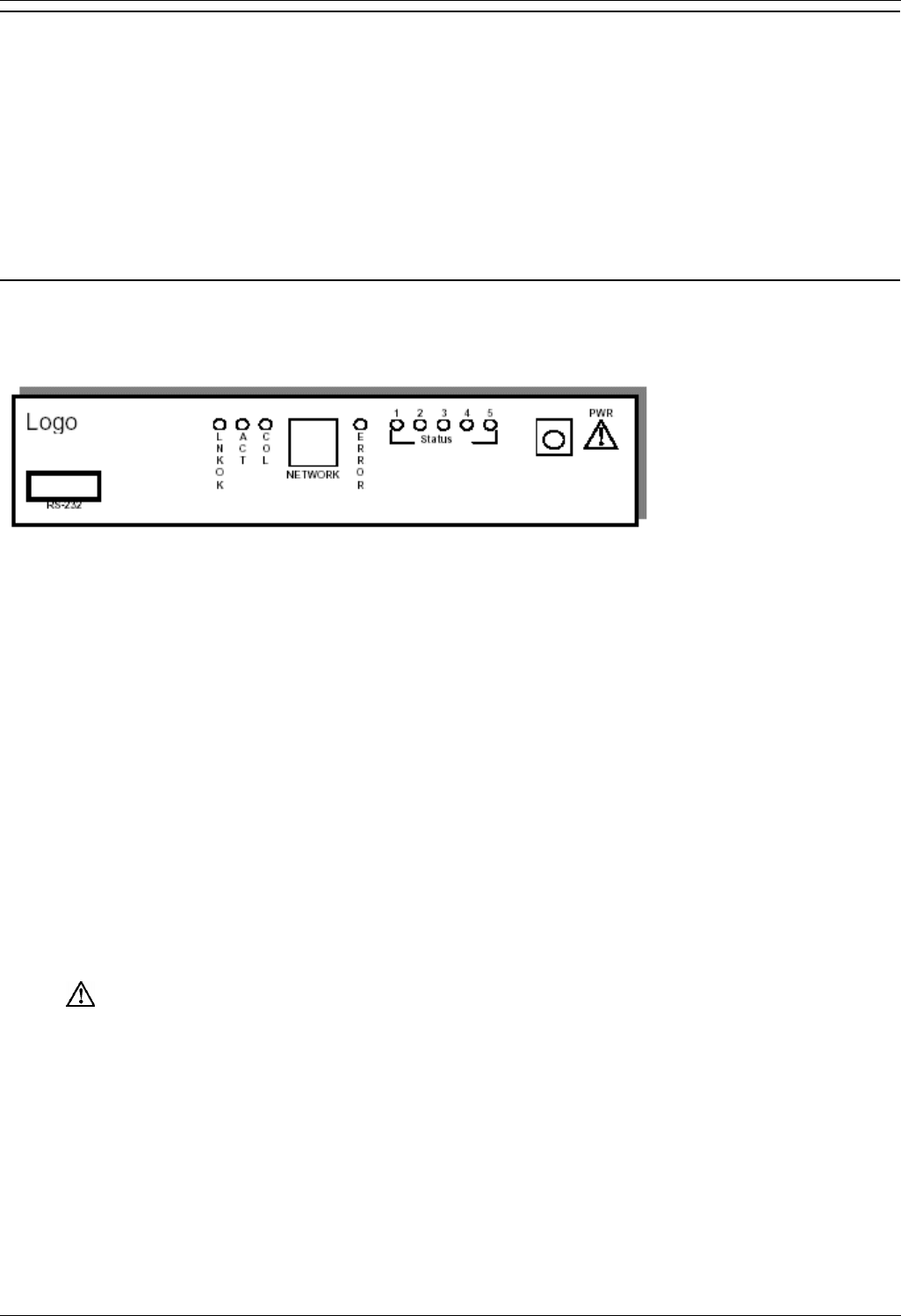
Front Panel of the AVPP
The AVPP’s front panel contains ports to connect to the LAN, and an administrative computer via an RS-
232 port. Status LEDs supply information about the AVPP’s functionality.
RS-232 Port – male DB-9 connector (DTE) used for RS-232 connection to a terminal, terminal
emulator, or modem for system administration.
Link LEDs:
LNKOK – lit when there is a network connection.
ACT – lit if there is system activity.
COL – lit if there are network collisions.
NETWORK – connects to wired (Ethernet) LAN.
ERROR LED – lit when the system has detected an error.
STATUS LEDs – indicate system error messages and status.
1 – heartbeat, indicates gateway is running.
2 – if active calls.
3, 4, 5 – currently unused.
PWR (power jack) – connects to the AC adapter supplying power to the system.
Warning:
Only use the Avaya-provided Class II AC Adapter with output 24VDC, 1A.

Overview
Wireless Installation and Configuration Guide Page 5
IP Office [15-601082] Issue [1] (1 June 2006)
Multiple AVPP
Multiple AVPP environments are those which have more than one AVPP in the same subnet in order to
accommodate larger systems and higher call capacity.
In a system comprised of multiple AVPPs using an IP protocol, a master AVPP must be identified. The
master AVPP server must have a static IP address. The wireless phones and the other AVPPs locate
the master by using a static IP address, DHCP, or DNS.
The loss of a non-master AVPP does not significantly affect the operation of the remaining AVPPs.
However, the loss of the master AVPP results in a loss of all communication between all of the AVPPs.
This also means that the loss of the master AVPP results in the loss of all active calls and wireless
phones cannot check-in until communication with the master is re-established.
Note
10, 20 and 100 AVPPs will not operate together in a network. The network must consist of all 10,
all 20 or all 100 AVPPs.
The Timing Function
In the IP PBX environment, AVPPs provide both the connection or "gateway" to the IP PBX for the
wireless phones and the "timing" function for active calls. This "gateway" function is distributed across
the AVPPs.
The number of active AVPPs is determined dynamically. Whenever AVPPs are added to or removed
from the system, the distribution of "timing" function for active calls, as well as the "gateway" function, is
affected.
Internal Gatekeeper
A gatekeeper is required in certain H.323 protocol systems. Currently, a gatekeeper is not supported.

Wireless Installation and Configuration Guide
Wireless Installation and Configuration Guide Page 6
IP Office [15-601082] Issue [1] (1 June 2006)
AVPP Capacity
The AVPP requires a Cat. 5 cable connection between its network port and the Ethernet switch. The
AVPP auto-negotiates to the type of port on the Ethernet switch and supports 10Base-T, 100Base-T, full-
duplex and half-duplex port types.
The following table shows the capacity of the AVPP010 and AVPP020:
Number of Handsets AVPP
Servers AVPP010 AVPP020
1 10 20
2 20 40
3 30 N/A
4 40 N/A
The following table shows the capacity of the AVPP100:
AVPP
Servers Calls per
Server Total
Calls Erlangs #Wireless
Phones 10%
use
#Wireless
Phones
15% use
Wireless
Phones
20% use
1 80 80 65 500 433 325
2 64 128 111 1000 740 555
3 60 180 160 1500 1067 800
4 58 232 211 2000 1407 1055
5 57 285 262 2500 1747 1310
6 56 336 312 3000 2080 1560
7 56 392 367 3500 2447 1835
8 55 440 415 4000 2767 2075
9 55 495 469 4500 3127 2345
10 55 550 524 5000 3493 2620
11 55 605 578 5500 3853 2890
12 54 648 621 6000 4140 3105
13 54 702 674 6500 4493 3370
14 54 756 728 7000 4853 3640
15 54 810 782 7500 5213 3910
16 54 864 836 8000 5573 4180
Note
These limitations are for AVPPs only. Each IP Office model has its own limitations for supporting
extensions. For example, IP Office 412 does not support more than 360 extensions. For specific
model number extension units, see the IP Office documentation.

Overview
Wireless Installation and Configuration Guide Page 7
IP Office [15-601082] Issue [1] (1 June 2006)
Overview of Wireless Phone
The 3600 series wireless phone is a mobile handset for workplace IP phone systems. The wireless
phone operates over an 802.11b wireless Ethernet LAN providing users with a wireless Voice over IP
(VoIP) extension. By integrating with IP Office, wireless phone users are provided with high-quality
mobile voice communications throughout the workplace. The wireless phone gives users the freedom to
roam throughout the workplace while providing all the features and functionality of an IP desk phone.
The 3600 series wireless phone provides a wireless extension to IP Office. The wireless phone resides
on the wireless LAN with other wireless devices using Direct Sequence Spread Spectrum (DSSS) radio
technology. The handset radio transmits and receives packets at up to 11Mb/s.
A wireless phone must be administered on IP Office for the specific features and lines to be accessed by
the wireless phone. After the handset is registered, it receives its configuration information from IP
Office.
The wireless phone supports Wired Equivalent Privacy (WEP) as defined by the 802.11 specification.
Avaya offers the product with both 40-bit and 128-bit encryption. WEP increases the security of the
wireless LAN to a level similar to a wired Ethernet LAN.
Notes
IP multicast addresses are used by the 3626 wireless phone Push-to-Talk (PTT) feature. This
requires that multicasting be enabled on the subnet used for the wireless phones, Avaya Voice
Priority Processor (AVPP) server, and telephony gateways.
Routers are typically configured with filters to prevent multicast traffic from flowing outside of
specific domains. The wireless LAN can be placed on a separate VLAN or subnet to reduce the
effects of broadcast and multicast traffic from devices in other network segments.
Requirements
1. A wireless LAN must be properly configured and operational through the use of 802.11b wireless
access points.
2. A TFTP server must be available on the network in order to load the appropriate software into the
wireless phones. For detailed instructions for loading software on wireless phones, see License
Management.
3. IP Office must be connected to the customer network and be completely operational.
4. The AVPP, which controls the QoS on the wireless LAN for the wireless phones, must be on the
same subnet as the wireless phone and have the proper versions of software. To download the
latest AVPP software, visit www.spectralink.com/softwareupdates.
5. Add a station on IP Office for each wireless phone. You will need to administer each wireless
phone as a 4606 IP phone.
Note
For IP Office 403, 406V1, 406V2 and 412 the Voice Compression Module (VCM) is required. The
IP Office Small Office Edition (SOE) has built-in VCM Channels for either 3 or 16 simultaneous
VoIP calls (depending on which SOE you have).
Configure your wireless phone to ensure that it is associated with the wireless LAN, has the appropriate
software and is registered to IP Office.
Note
The AVPP and all access points must be on the same subnet.

Wireless Installation and Configuration Guide
Wireless Installation and Configuration Guide Page 8
IP Office [15-601082] Issue [1] (1 June 2006)
Phone Specifications
Radio Frequency 2.4000 - 2.4835 GHz
Transmission Type Direct Sequence Spread Spectrum (DSSS)
Transmit Date Rate Up to 11 Mb/s
Radio QoS Avaya Voice Priority Processor (AVPP)
Wireless Security Wired Equivalent Privacy (WEP), 40bit and 128bit
FCC Certification Part 15.247
Management DHCP, TFTP
Voice Encoding G.711, G.720a/ab
VoIP Protocols CCMS
Transmit Power 100 mW peak, < 10 mW average
Display 2 x 16 character alphanumeric, plus line and status
indicators
3616 Dimensions 5.5" x 2.0" x 0.9"
3620 Dimensions 5.5" x 2.0" x 0.9"
3626 Dimensions 5.9" x 2.2" x 1.0"
3616 Weight 4.2 ounces
3620 Weight 4.2 ounces
3626 Weight 6.0 ounces
3616 Battery
Capacity 4 hours talk time, 80 hours standby
3620 Battery
Capacity 4 hours talk time, 80 hours standby
3626 Battery
Capacity 4 hours talk time, 80 hours standby
If PTT is enabled, the standby battery capacity is
decreased to approximately 30 hours.

Overview
Wireless Installation and Configuration Guide Page 9
IP Office [15-601082] Issue [1] (1 June 2006)
System Components
3600 Series Wireless Phones
As they move throughout the building, users can carry wireless phones to make and receive calls. The
wireless phones are to be used on-premises; they are not cellular or satellite phones. They are
connected to the facility's existing phone system and to the gateway or IP gateway. Just like wired
phones, they can receive calls directly, receive transferred calls, transfer calls to other extensions and
make outside and long distance calls (subject to the restrictions applied in your facility).
The wireless phones can operate on an 802.11b wireless network and can operate at a transmission
rate of up to 11Mb/s.
3616 Wireless Phone
The 3616 wireless phone is a lightweight, durable handset specifically designed for mobile
workplace use within a facility using IP Office and 802.11b access points in a wireless LAN. The
phone supports five predefined feature keys and a mixture of six programmable line and feature
keys. Among other features, the wireless phone can receive calls directly, receive transferred
calls, transfer calls to other extensions, make conference calls, and make outside and long
distance calls (subject to the restrictions applied in your facility.)
3620 Wireless Phone
The 3620 wireless phone is a sturdier version of the 3616 phone and is ideally suited for
healthcare environments. The handset has the same features as the 3616 phone.
3626 Wireless Phone
The 3626 wireless phone offers a durable design with push-to-talk capabilities as well as the
same features as the 3616 phone.
The wireless phones use direct sequence spread spectrum radio technology (DS) to transmit audio
packets over wireless LAN access points that support the Avaya Wireless PC card.
Avaya Voice Priority Processor
Avaya Voice Priority Processor (AVPP) is an Ethernet LAN appliance that works with access points to
provide Quality of Service (QoS) on the wireless LAN. All packets to and from the wireless phones, pass
through the AVPP and are encapsulated for prioritization as they are routed to and from IP Office. AVPP
is fully compliant with the IEEE802.11 and 802.11b standards.
AVPP is required for QoS because the current IEEE802.11b wireless LAN standard does not provide a
mechanism for differentiating audio packets from data packets.
The following AVPP servers are available to meet customer needs:
AVPP100: Serves 80 calls simultaneously.
AVPP020: Serves 20 powered-on handsets.
AVPP010: Serves 10 powered-on handsets.

Wireless Installation and Configuration Guide
Wireless Installation and Configuration Guide Page 10
IP Office [15-601082] Issue [1] (1 June 2006)
IP Office
The call-processing component of the Avaya IP telephony solution.
The following IP Office units (equipped with VCM) are supported:
Avaya IP Office 403
Avaya IP Office 406 V1/V2
Avaya IP Office 412
The following IP Office Small Office Edition units (equipped with built-in VoIP) are supported:
Avaya IP Office - Small Office Edition 3 VoIP
Avaya IP Office - Small Office Edition 16 VoIP
Access Points
Supplied by either Avaya or third party vendors, access points provide the connection between the wired
Ethernet LAN and the wireless (802.11b) LAN. Access points must be positioned in all areas where
wireless phones will be used. The number and placement of access points will affect the coverage area
and capacity of the wireless system. Typically, the requirements for use of wireless phones are similar to
that of wireless data devices.
The wireless phones must connect to access points that use AVPP. For a complete list of access points
supported, go to:
www.spectralink.com/consumer/resources/wifi_compatibility.jsp
Ethernet Switch
Interconnects multiple network devices, including the AVPP, IP Office, IP Phones and the access points.
Ethernet switches provide the highest performance networks, which can handle combined voice and
data traffic, and are required when using the wireless phones.
Although a single Ethernet switch network is recommended, the wireless phones and the AVPP can
operate in larger, more complex networks, including networks with multiple Ethernet switches, routers,
VLANs and/or multiple subnets. However, in such networks, it is possible for the Quality of Service
(QoS) features of the AVPP to be compromised and voice quality may suffer. Any network that consists
of more than a single Ethernet switch should be thoroughly tested to ensure any quality issues are
detected.
Note
The 3600 series wireless phones cannot “roam” from one subnet to another. If routers and
multiple subnets are in use, the wireless phones must only use access points attached to a single
subnet, or be powered off and back on to switch to a different subnet.

Overview
Wireless Installation and Configuration Guide Page 11
IP Office [15-601082] Issue [1] (1 June 2006)
Router
A router is an optional component in the wired Ethernet LAN infrastructure that separates a wired LAN
into segments so that network traffic is restricted to those segments that are directly involved in the
communication. Installation of a network router is recommended in larger networks, where there may be
significant network traffic not related to the wireless LAN. A router will isolate the wireless LAN from the
associated wired LAN so that they are not impacted by each others’ traffic. The gateways, access points
and their associated Ethernet switch must all be on the same “side” of the router.
Administrative Computer
A computer is required for setup and maintenance of the AVPP. This computer can be temporarily
connected directly to the component or to the network, a dedicated computer is not required. Some
installations use a laptop to configure and maintain system components.
TFTP Server
A TFTP server is required in the system to distribute software to the wireless phones and AVPP. TFTP
may be on a different subnet than IP Office, AVPP, access points and/or wireless IP phones. AVPP 10,
20 and 100 do not support IP Office internal TFTP server.
To download Avaya's free TFTP server, go to www.avaya.com/support.
Note
An AVPP is required on each subnet. The access points must be on the same subnet(s) as the
AVPP(s).
IP Multicast Addresses
IP multicast addresses are used by the 3626 wireless phone system. This requires that multicasting be
enabled on the subnet used for the wireless phones and AVPP servers. Routers are typically configured
with filters to prevent multicast traffic from flowing outside of specific domains. The wireless LAN can be
placed on a separate VLAN or subnet to reduce the effects of broadcast and multicast traffic from
devices in other network segments.

Wireless Installation and Configuration Guide
Wireless Installation and Configuration Guide Page 12
IP Office [15-601082] Issue [1] (1 June 2006)
The Phone Display
Alphanumeric
The wireless phone display has two lines capable of displaying 16 alphanumeric characters each.
Display information (provided by IP Office when the wireless phone is off-hook) will be passed directly to
the wireless phone display. The wireless phone will emulate the 4606 phone display handling. Certain
characters may be used by IP Office that are not implemented in the wireless phone such as definable
and special characters.
In IP Office, the MENU key is unavailable. The softkeys operate with a toggle function. To activate a
softkey feature, press the left or right side of the corresponding key.
To display the standby menu, press and briefly hold FCN.
To scroll through the menu, press Up and Down.
To select a menu item, press Select.
Voicemail Icon
The voicemail icon is activated in a similar fashion as the message indicator of the display set.
Ringing and Tones
The ringing types (normal or vibrator) are programmed by the wireless phone user into the wireless
phone and are not accessible or changeable by IP Office. Whenever possible the audible and vibrating
ringer on the wireless phone will follow the cadence provided by IP Office.
Audio Features
The 4606 speakerphone features are not available on the wireless phone.
Line Indicators
The line indicators on the wireless phone will convert to a solid or flashing number to mimic the LEDs
next to Line keys on the 4606 phone.
Note
The wireless phone will indicate line numbers based on the order line assignments are received
from the IP Office, regardless of which button the line is assigned to during system
administration.

Wireless Installation and Configuration Guide Page 13
IP Office [15-601082] Issue [1] (1 June 2006)
Introducing the AVPP
Overview
As shown in the system diagram, the AVPP is connected to the Ethernet switch. The specifications
covered here, allow for flexibility in physical placement of the components within the stated guidelines.
See the Setup and Administration Guide for your vendor's IP system, for information on LAN
requirements, network infrastructure and IP addressing.
Required Materials
The following equipment must be provided by the customer:
Power Outlet – must accept Avaya provided AC adapter.
Backboard space – the AVPP is designed to be wall mounted to ¾” plywood securely screwed
to the wall.
Screws – required to mount the AVPP to the wall. Four #8 - ¾” panhead wood screws (or similar
device) are required.
Cat. 5 Cable – RJ-45 connector at the AVPP. Connection to the Ethernet switch.
Locating the AVPP
The AVPP measures approximately 4 x 12.5 x 7 inches, and weighs about five pounds. The unit can be
wall mounted, vertically or horizontally, over ¾” plywood. The AVPP can also be rack mounted using a
rack mount kit (sold separately).
Locate the AVPP in a space with:
Sufficient backboard mounting space (for wall mount) and proximity to the LAN access device
(switched Ethernet hub) and power source.
Easy access to the front panel, which is used for cabling.
A maximum distance of 325 feet (100 meters) from the Ethernet switch.

Wireless Installation and Configuration Guide Page 14
IP Office [15-601082] Issue [1] (1 June 2006)
AVPP Configuration
Introduction
During initial setup of the AVPP, the IP address is established and the maximum number of active calls
per access point is set. Optionally, you may enter a hostname and a location for software updates via
TFTP.
Note
Where SVP is documented in this section, AVPP applies.
Connecting to the AVPP
The initial connection to the AVPP must be made via a serial connection to establish the AVPP’s IP
address. After the IP address is established, connection to the AVPP can be done via the network using
Telnet. It is recommended that the basic setup actions occur while the serial connection is made.
Connecting via the Serial Port
1. Using a DB-9 female, null-modem cable, connect the AVPP to the serial port of a terminal or PC.
2. Run a terminal emulation program (such as HyperTerminal™) or use a VT-100 terminal with the
following configuration:
Bits per second: 9600
Data bits: 8
Parity: None
Stop bits: 1
Flow control: None
3. To display the AVPP login screen, press Enter.
4. Enter the default login: admin and default password: admin. These are case sensitive. The
NetLink SVP-II System menu is displayed.
AVPP Configuration
Wireless Installation and Configuration Guide Page 15
IP Office [15-601082] Issue [1] (1 June 2006)
Connecting via Telnet
Note
Telnet can only be used after the AVPP’s IP address is configured.
The Telnet method of connection is used for routine maintenance of the Avaya server for both local and
remote administration, depending on your network.
To connect via Telnet, run a Telnet session to the IP address of the AVPP. Once you connect and log in,
the NetLink SVP-II System menu is displayed.
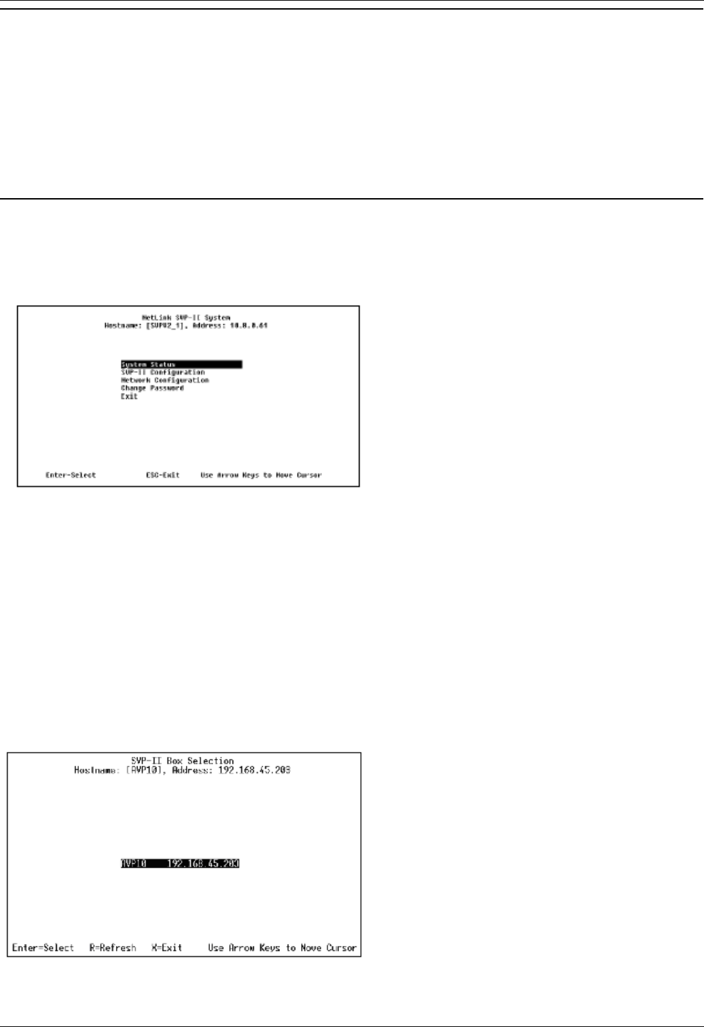
AVPP System Menu
When you connect via the serial port or via Telnet (for the first time) the following main menu is
displayed:
The screen displays:
System Status - menu for viewing error messages, status of operation and software code
version. The 170 series software is required in the Alcatel IP environment. You can check the
version currently installed on AVPP through the System Status menu, see Software Version.
SVP-II Configuration - allows you to set the mode and reset the system.
Network Configuration - allows you to set network configuration options, including IP address
and hostname.
Change Password - allows you to change the password for AVPP access.
After you have configured a name for the AVPP, the following screen is displayed when you first login to
the AVPP:
The screen displays the name and IP address of the AVPP. To display the main menu, press Enter.
Wireless Installation and Configuration Guide
Wireless Installation and Configuration Guide Page 16
IP Office [15-601082] Issue [1] (1 June 2006)
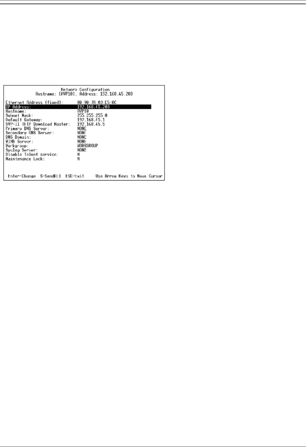
Network Configuration
The IP address and other network settings are established via the Network Configuration screen. This
is also where you may optionally establish a hostname and enter the IP address of the location of any
software updates.
For more information about installing software updates via TFTP, see Software Maintenance.
From the main menu, scroll to Network Configuration and press Enter. A screen similar to the
following is displayed:
The screen displays:
IP Address - enter the IP address of the AVPP, defined by your system administrator.
Hostname (optional) - change the default host name, if desired. This is the name of the AVPP to
which you are connected, for identification purposes only. You cannot enter any spaces in this
field.
SVP-II TFTP Download Master - this entry indicates the source of software updates for the
AVPP. Valid source locations are:
NONE - disables.
IP Address - the IP address of the network TFTP server that will be used to transfer
software updates to the AVPP.
DNS Server and DNS Domain - these settings are used to configure domain name services.
Consult your system administrator for the correct settings. These can also be set to DHCP. This
will cause the DHCP client in the AVPP to attempt to automatically get the correct setting from
the DHCP server. The DHCP setting is only valid when the IP address is also acquired using
DHCP.
WINS servers - these settings are used for Windows Name Services. Consult your system
administrator for the correct settings. These can also be set to DHCP. This will cause the DHCP
client in the AVPP to attempt to automatically get the correct setting from the DHCP server. The
DHCP setting is only valid when the IP address is also acquired using DHCP.
Note
When the name services are set up correctly, the AVPP can translate hostnames to IP
addresses. Using Telnet, it is also possible to access the AVPP using its hostname
instead of the IP address.

AVPP Configuration
Wireless Installation and Configuration Guide Page 17
IP Office [15-601082] Issue [1] (1 June 2006)
Workgroup - as set in WINS.
Syslog Server - logging can be set to Syslog or NONE. If Syslog is set, a message is sent to the
Syslog server when an alarm is triggered.
Disable Telnet service - prevents Telnet access into the AVPP server. Reset the AVPP server
for the change to take effect. Upon reset the Telnet protocol server is not started.
The AVPP must be reset in order to set the configuration options. If the AVPP is in Maintenance Lock
and you press Esc, you will be prompted to reset the AVPP. At the reset prompt, press Y (Yes).
To manually reset AVPP, select Reset in the SVP-II Configuration screen and then press Y (Yes).
Send All
In an IP system with multiple AVPPs, the SendAll option is provided to speed configuration and ensure
identical settings. The S=SendAll option allows you to send that configuration parameter to every AVPP
on the LAN.
SendAll can only be used after the IP address is established on each AVPP via the serial connection. If
you anticipate identical settings across the LAN, set the IP address and custom hostname (if desired) for
each AVPP using the initial serial connection. Connect via the LAN and use SendAll to set identical
configuration options for all AVPPs.
If SendAll is to be utilized in your system, all passwords must be identical.
Warning
Do not change the password at the initial configuration if SendAll is desired.
Use the default password and change it globally, if desired, after a LAN connection is established for all
AVPPs.
If independent administration of each AVPP is desired, the passwords may be set at initial configuration.
Note
The IP address of the master AVPP can be changed in this menu. After rebooting the system,
you can change alias IP addresses in each of the other AVPP servers without error.
Wireless Installation and Configuration Guide
Wireless Installation and Configuration Guide Page 18
IP Office [15-601082] Issue [1] (1 June 2006)
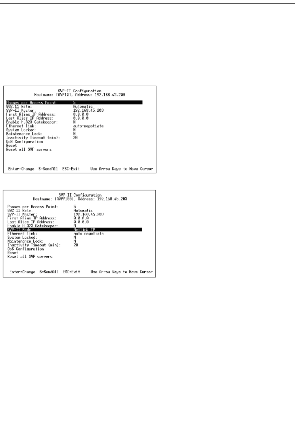
AVPP Configuration
The SVP-II Configuration screen allows you to set the mode of the AVPP for an IP environment. It is
also where you can lock the AVPP for maintenance and reset the AVPP after maintenance.
If the IP address is changed, the AVPP will automatically lock for maintenance. When this Maintenance
Lock occurs, the AVPP must be reset upon exit. All active calls are terminated during a reset.
From the main menu, scroll to SVP-II Configuration and press Enter.
For the AVP 10 or 20, the following screen is displayed:
For the AVP 100, the following screen is displayed:
Complete the configuration changes:
Phones per Access Point - enter the number of simultaneous calls supported for your type.
Access point specifications are detailed in the configuration notes for each brand and type.
802.11 Rate - select 1MB/2MB to limit the transmission rate between the wireless phones and
access points. To allow the wireless phone to determine its rate (up to 11Mb/s), select
Automatic.

AVPP Configuration
Wireless Installation and Configuration Guide Page 19
IP Office [15-601082] Issue [1] (1 June 2006)
SVP-II Master - the master AVPP must be identified in an IP system. Select one of the following
identification options:
To statically configure the IP address of the master AVPP in each of the AVPPs, enter the
IP address.
To statically configure the IP address of the master AVPP in a DHCP server and
configure each of the AVPPs to get the information from the DHCP server, enter DHCP. If
DHCP is used, the IP address of the master AVPP server must be configured in the
DHCP server. For more information about DHCP integration factors, see the wireless
phone interface guide for your IP environment.
To statically configure the IP address of the master AVPP in a DNS server and configure
each of the AVPPs to retrieve this information from the DNS server, enter DNS. If DNS is
used, the IP address of the master AVPP server must be configured in the DNS server.
For an explanation of the master AVPP, see Introduction to AVPP.
First Alias IP Address/Last Alias IP Address - enter the range of IP addresses this AVPP may
use when acting as a proxy for the wireless phones. Alias IP addresses are not necessary in
Avaya systems.
Note
All alias addresses must be on the same subnet as the AVPP server and cannot be duplicated on
other subnets or AVPPs. There is no limit to the number of addresses that can be assigned,
however, the capacity of each AVPP is 500 wireless phones.
Enable H.323 Gatekeeper - the Gatekeeper function is not supported. Enter N (No).
Ethernet link - the AVPP will auto-negotiate unless there is a need to specify a link speed.
System Locked - this option is used to take the system down for maintenance. The default entry
is N (No). To prevent any new calls from starting, set as Y (Yes). To restore normal operation,
return to N.
Maintenance Lock - the system automatically sets this option to Y (Yes), after certain
maintenance activities that require reset (such as changing the IP address). Maintenance Lock
prevents any new calls from starting.
Note
This option is automatically set by the system and cannot be changed by the system
administrator.
To clear the Maintenance Lock, reset the system at exit.
Inactivity Timeout (min) - set the number of minutes the administrative module can be left
unattended before the system closes it. This number can be from 1 to 100. If it is set to zero (0),
the administrative module will not close due to inactivity.
QoS Configuration - select this option to set the DSCP tags and the 802.1p tags. See QoS
Configuration.
Reset System - if this option is selected, you will be prompted to reset the AVPP upon exiting
this screen. Resetting the AVPP will terminate any calls in progress.
Note
The AVPP should be reset at the end of any maintenance procedure that requires a reset either
via Maintenance Lock or manually via Reset System.

Wireless Installation and Configuration Guide
Wireless Installation and Configuration Guide Page 20
IP Office [15-601082] Issue [1] (1 June 2006)
QoS Configuration
If QoS Configuration is selected from the SVP-II Configuration screen. A screen similar to the following
is displayed:
Tags set packet priorities for QoS. Either DSCP or 802.1p tags may be used.
DSCP Tag - DSCP (Differentiated Services Code Point) is a QoS mechanism for setting relative
priorities. In the IP header, packets are tagged with a DSCP field for type of service.
Traffic Class
Administration - tags set the priority for Telnet, TFTP and other administrative traffic.
Administrative traffic can have the lowest priority because it does not require voice quality.
WT (In call)/WT (Standby) - in call traffic requires voice quality and may be set to a
higher priority than standby traffic.
RTP - audio traffic to the IP PBX. It requires voice quality.
PBX - traffic not audio to the PBX.
Inter-SVP2 - the information passing protocol the AVPP servers use to communicate with
each other.

AVPP Configuration
Wireless Installation and Configuration Guide Page 21
IP Office [15-601082] Issue [1] (1 June 2006)
Change Password
The password to access the AVPP may be changed, if desired. From the Main Menu, select Change
Password. A screen similar to the following is displayed:
Enter the information and either select Set Password or press S.
The password parameters are:
More than four characters.
First character must be a letter; other characters may be numbers and letters.
No dashes, spaces or punctuation marks (alphanumeric only).
Caution
Remember to keep the password safe as it cannot be reset remotely.

Wireless Installation and Configuration Guide Page 22
IP Office [15-601082] Issue [1] (1 June 2006)
AVPP Administration
Introduction
Whenever an AVPP is removed from the system, wireless phones that are using the system will be
affected. If the removal of the AVPP is intentional, the administrator should lock and idle the system,
prior to removing an AVPP. Whenever an AVPP is added to the system, the change is seamless and
does not affect the wireless phone calling functionality.
Adding an AVPP
In the IP PBX environment, a new AVPP is detected within two seconds of being added to the system
(booted/configured/connected). When detected, any wireless phone that is not active in a call will
immediately be forced to check out and check in again. Any wireless phone in a call will immediately
switch to the AVPP that should provide its 'timing' function. This switch should not be noticeable to the
user since it is similar to a normal handoff between access points. When the call is ended, the wireless
phone will be forced to checkout and checkin again.
Removing an AVPP
When a AVPP is removed from the system, it is detected within two seconds. Wireless phones not active
on calls are immediately forced to check out and check in again.
For wireless phones active in calls, two possible scenarios can occur:
If the AVPP that was removed was providing the 'gateway' function for the wireless phone, then
the call is lost and the wireless phone is forced to check in again.
If the AVPP that was removed was providing the 'timing' function for the call, then call will switch
to the AVPP that should now provide the 'timing' function.
Note
During the two seconds while the loss of the AVPP is being detected, the audio for the call will be
lost.
Changing the Master AVPP
In the event the master AVPP loses communication with the network, the wireless phone system will fail.
All AVPPs will lock and all calls will be lost and no calls will be able to be placed. Therefore, if the master
AVPP needs replacing, be sure that the system can be brought down with minimal call interruption. Be
sure to reset all AVPPs after the master has been replaced. If the IP address of the master is changed, it
must be changed in all AVPPs.
Wireless Installation and Configuration Guide Page 23
IP Office [15-601082] Issue [1] (1 June 2006)
IP Office Configuration
Introduction
You need to configure the wireless phones as VoIP extensions on IP Office.
Note
The IP Office Manager screen shots below are from IP Office Version 3.1. Depending on the
version of your IP Office, the exact screen displays may differ. However, the steps to cover
should be similar.
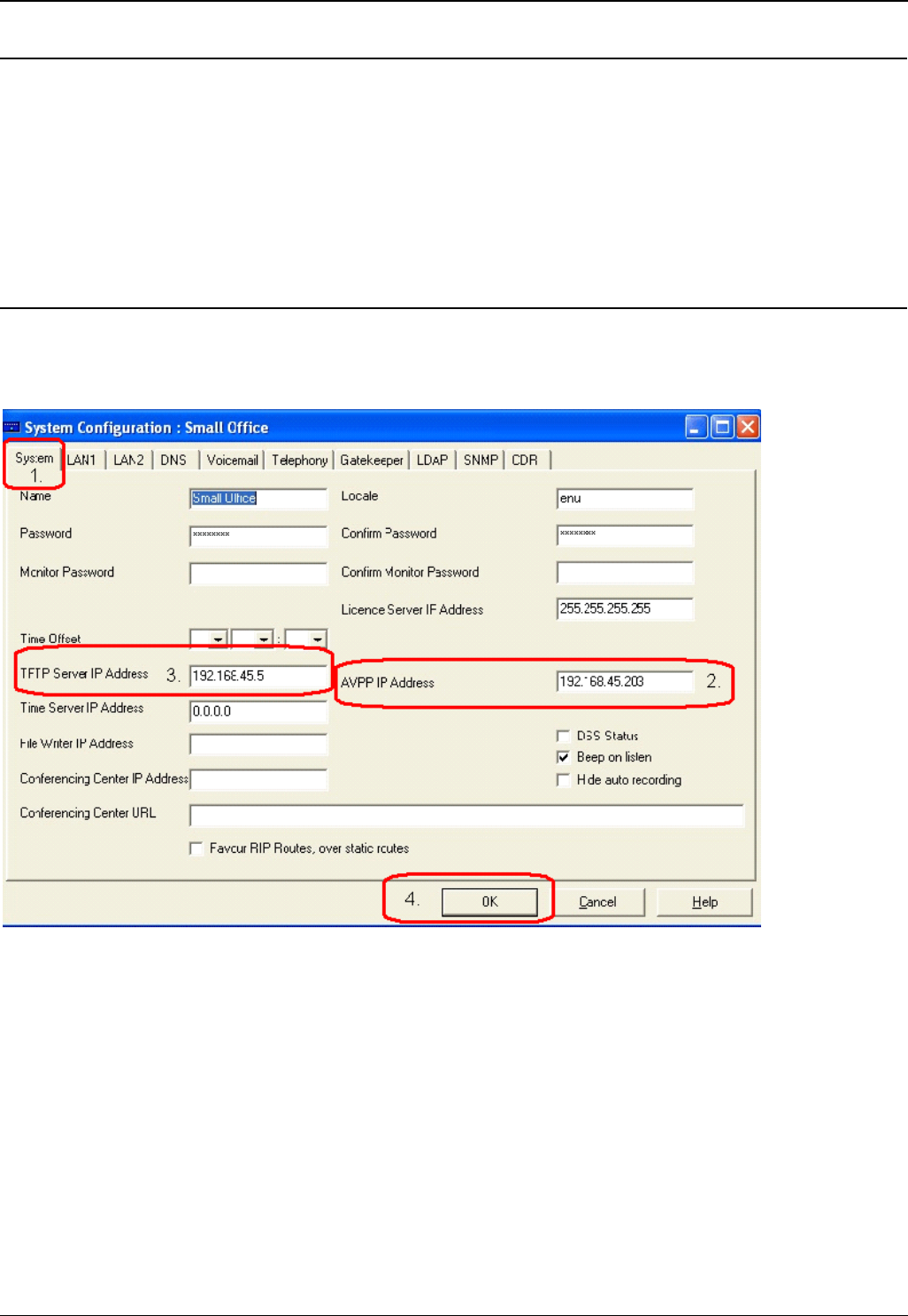
Configuring the Wireless Phone with IP Office Manager
1. Launch IP Office Manager and from the System Configuration screen, click the System tab.
2. Enter the master AVPP IP Address.
3. Enter the FTP Server IP Address.
4. Click OK.
Wireless Installation and Configuration Guide
Wireless Installation and Configuration Guide Page 24
IP Office [15-601082] Issue [1] (1 June 2006)
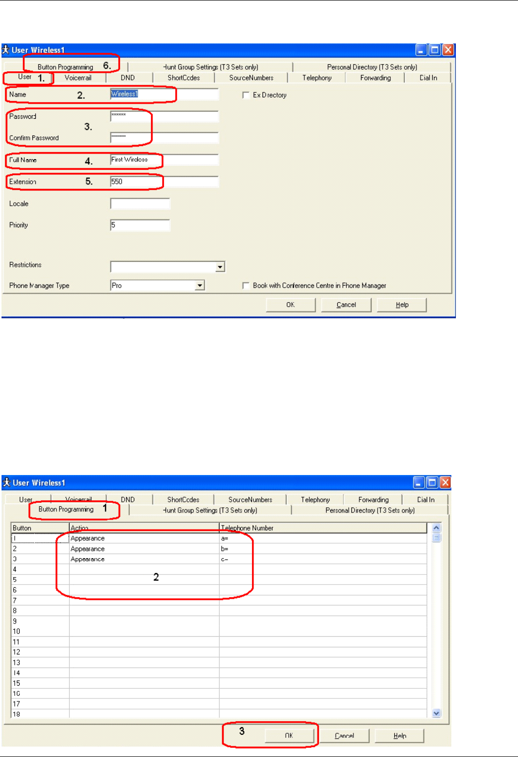
Adding a New User
1. Click the User tab.
2. Enter the Name of the user.
3. Enter the Password and confirm.
4. Enter the Full Name of the user.
5. Enter the Extension number of the user.
6. Click the Button Programming tab.
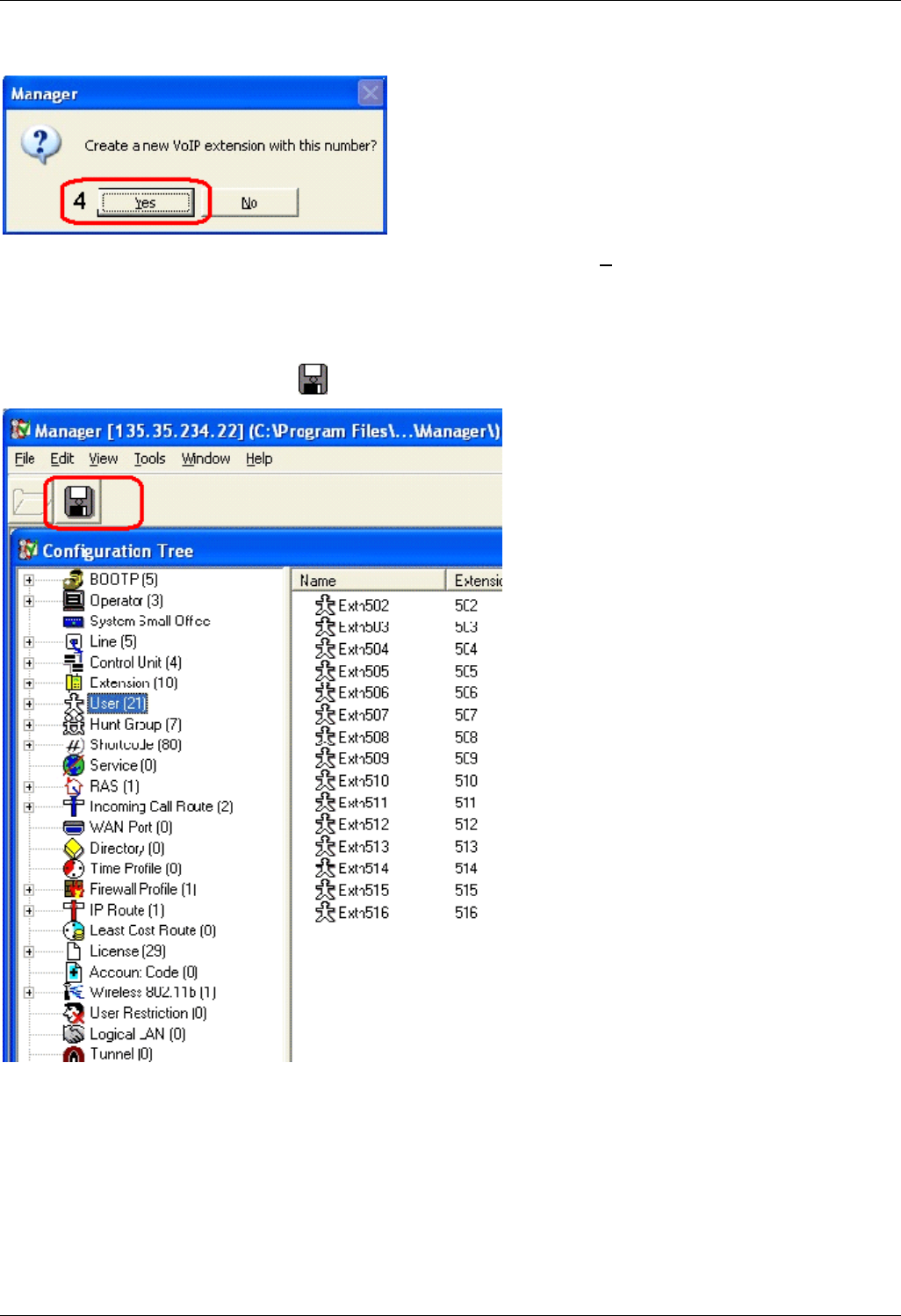
Button Programming
1. Click the Button Programming tab.
IP Office Configuration
Wireless Installation and Configuration Guide Page 25
IP Office [15-601082] Issue [1] (1 June 2006)
2. Enter the 6 line buttons for the user extension.
3. Click OK.
4. When you are prompted to create a new VoIP extension, click Yes. Repeat this process for all
wireless user extensions.
Updating the Configuration
From the Configuration Tree, click to merge the configuration.

Wireless Installation and Configuration Guide
Wireless Installation and Configuration Guide Page 26
IP Office [15-601082] Issue [1] (1 June 2006)
IP Office Integration Factors
Voice Messaging Access
To access voicemail, dial *17. For verification, check with your system administrator.
CODECS
The wireless phones are compatible with the G.711 and G.729a/ab codecs. There is no setting required
on the wireless phone. If the wrong codec is used, there will be no voice path.
DHCP
Dynamic Host Configuration Protocol (DHCP) is a standardized protocol that enables clients to be
dynamically assigned with various configuration parameters, such as an IP address, subnet mask,
default gateway, and other critical network configuration information. DHCP servers centrally manage
such configuration data, and are configured by system administrators with settings that are appropriate
for a given network environment. The wireless phone will use the following DHCP options, if DHCP use
is enabled:
Option Meaning
3 Default Gateway
6 DNS Server
15 Domain Name
66 TFTP Server
151 Avaya Voice Priority
Processor
176 Avaya Specific Options
Note
The above DHCP options are available if you are using a Win2K DHCP server on your network.
TFTP
The wireless phone uses TFTP to update its software over the 802.11 wireless LAN. The 3600 series
wireless phones and the AVPPs, only support an external TFTP server with IP Office.

IP Office Configuration
Wireless Installation and Configuration Guide Page 27
IP Office [15-601082] Issue [1] (1 June 2006)
DNS
Domain Name System (DNS), an industry-standard protocol, locates computers on an IP-based network.
IP networks rely on number-based addresses to move information on the network. However, users are
better at remembering friendly names than number-based addresses, so, it is necessary to translate
user-friendly names into addresses that the network can recognize. The wireless phone will use DNS to
automatically translate names into IP addresses for these components: TFTP server, AVPP and IP
Office.
Entering an Extension and Password
Several conditions (new phone, Extension Error, Password Error, and Extension in use) can result in the
wireless phone asking the user for a new extension and password. The entry process is described
below. When a new extension or password is being entered, the asterisk (*) key can be used to back up
and correct an error.
The wireless phone will display:
Ext. =XXX
#=OK New =
At this point, a new extension can be entered, or if # is pressed, the wireless phone will retain the current
extension.
After a new extension is entered, press # to continue.
The wireless phone will then display:
Password = ********
# = OK
A new password can be entered at this time, or if # is pressed, the wireless phone will continue with its
current password.
After a new password is entered, press # to continue.
Extension Error
If the IP Office unit (or all, if there is more than one) does not recognize the extension that the phone is
trying to register with, the wireless phone will display:
Extension Error
This will last 5 seconds, and then the wireless hone will ask the user to enter a new extension and
password.

Wireless Installation and Configuration Guide
Wireless Installation and Configuration Guide Page 28
IP Office [15-601082] Issue [1] (1 June 2006)
Password Error
If the wireless phone has an incorrect password, the display will show:
Password Error
# to continue
To enter a new extension and password, press # to continue.
Extension Override
IP Office will detect when a wireless phone tries to register with the same extension as any phone that is
already registered to that extension. If this happens, the wireless phone will display:
Extension in use
# to continue
To continue, press #.
If the user chooses to continue on with the override information, the wireless phone will register with the
override bit set. Any phone currently registered with the given extension will be unregistered, and any
activity on the currently registered phone will be stopped. If that phone is in a call, it will be dropped.
If the user does not want to override the existing extension, either enter a different extension and
password, or simply power off the wireless phone.
Note
If two wireless phones are assigned to the same extension, the IP Office unit will not properly
resolve the registration conflict due to the presence of the AVPP. Both wireless phones may fail
to operate properly.
Retry/Restart
Some errors will result in the following display, once # is pressed to continue:
* to Retry
# to Restart
To immediately retry registering with IP Office, press *. To restart the wireless phone, press # (which will
take about 20 seconds)

Wireless Installation and Configuration Guide Page 29
IP Office [15-601082] Issue [1] (1 June 2006)
Wireless Phone Installation
Introduction
This section contains information on the installation and configuration of the wireless phone on IP Office.
IP Office acts as a routing mechanism for all wireless phones on its system. Information is routed from
the phone to IP Office and to the AVPP.
The AVPP is the Quality of Service (QoS) mechanism that is implemented in the wireless phone and
access point to enhance voice quality. AVPP gives preference to voice packets on the wireless medium,
increasing the probability that all voice packets are transmitted efficiently. These voice packets are then
re-routed through IP Office and back to the wireless phone.
The IP Office units currently supported with the wireless phones:
• Avaya IP Office 403
• Avaya IP Office 406 (V1 and V2)
• Avaya IP Office 412
Avaya IP Office – Small Office Edition can be optioned as an 802.11b access point (WiFi pcmcia card
and IP400 ACCESS POINT RFA license, to activate the access point software) but without QoS. The
access point is configurable via IP Office Manager.
Other wireless solutions are available for the IP Office – Small Office Edition.
Notes
The setup for the 3600 series wireless phones requires four major steps:
1. The configuration of the AVPP.
2. The configuration of IP Office.
3. The configuration of the Access Points.
4. The configuration of the 3616/3620/3626 wireless phones.
With IP Office, the access point resides on the LAN and is configured based on the
manufacturer’s guidelines and manuals. For a list of access points supported, go to
www.spectralink.com/consumer/resources/wifi_compatibility.jsp.
Wireless Installation and Configuration Guide
Wireless Installation and Configuration Guide Page 30
IP Office [15-601082] Issue [1] (1 June 2006)
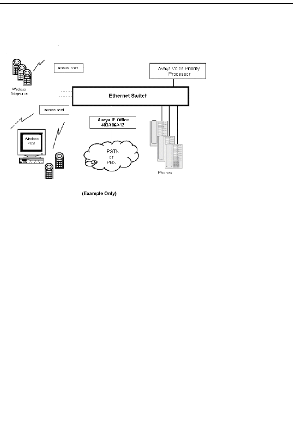
System Configuration
The following diagram shows IP Office residing on a network with a wireless LAN access point, the
AVPP and 3600 series phones:

Wireless Phone Installation
Wireless Installation and Configuration Guide Page 31
IP Office [15-601082] Issue [1] (1 June 2006)
Sample Installation and Configuration
A sample configuration set-up is available following the instructions below.
Note
Before you begin downloading software upgrades, you must create a Spectralink Login and
password.
If you have an IP Office unit, do the following to set-up the wireless phones:
1. To create a VoIP extension on IP Office, you must first download the firmware upgrades for the
phones and the AVPPs from the SpectraLink website: www.spectralink.com/softwareupdates
2. For the 10, 20 or 100 AVPP software, click Infrastructure. In the Product column, locate NetLink
SVP Server, and do the following:
a. Download the .EXE. For the 10 and 20 AVPP, download Netlink SVP Server.exe.
For the 100 AVPP, download Netlink SVP Server_01.exe.
b. Double-click the .EXE file and place the files in the same sub-directory as your
TFTP server is pointed to.
Note
10, 20 and 100 AVPPs will not operate together in a network. The network must consist of
all 10, all 20 or all 100 AVPPs.
For the wireless phone software, click Handsets. In the Product column, locate Netlink-
e340/h340/i640-Avaya and do the following:
a. Download the .EXE.
b. Double-click the .EXE file and place the files in the same sub-directory as your
TFTP server is pointed to.
3. Refer to the manufacturer’s documentation to configure the access point with the following
information:
Access Point IP Address
Individual Access Point Name
Frequency Channel
Security Key Information
4. Using a Cat. 5 Ethernet cable, connect the IP Office unit’s LAN port to the AVPP’s Network port.
5. To configure the AVPP, see AVPP Configuration.
6. Create a VoIP extension for each wireless phone.
7. Configure the wireless phone.

Wireless Installation and Configuration Guide
Wireless Installation and Configuration Guide Page 32
IP Office [15-601082] Issue [1] (1 June 2006)
Sample Setup
Below is a sample configuration designed as a quick reference.
Sample Information
Item IP Address
Avaya Voice Priority Processor
(AVPP) 192.168.42.3
Avaya IP Office 403/406/412 192.168.42.1
PC 192.168.42.10
AVPP Configuration Screen via Hyperterminal
Title State Comment
Error Status Alarms System error display
Network Status Status of networks
Software
Versions Current software version
on the AVPP
AVPP Configuration
Hostname: Sample 1, Address: 192.168.42.3
Title State Comment
Phones per access
point 3 Dependent on the access
point
802.11 Rate: Automatic/1MB
2MB only Data rate speed
AVPP Master: 192.168.42.3 AVPP IP address
AVPP Mode: Netlink IP Leave as default
Ethernet link: Auto-negotiate Leave as default
System locked: N Leave as default
Maintenance lock: N Leave as default
Reset system Y/N Leave as default

Wireless Phone Installation
Wireless Installation and Configuration Guide Page 33
IP Office [15-601082] Issue [1] (1 June 2006)
AVPP Network Configuration
Title State Comment
Ethernet Address
(fixed): 00:90:7A:01:24:93 Leave as default
IP Address: 192.168.42.3 The AVPP unit
Hostname: Sample1 System host
name
Subnet Mask: 255.255.255.0 Leave as default
Default Gateway: 192.168.42.1 IP Office unit
AVPP TFTP
Download Master: 192.168.42.1 PC containing
AVPP software
Primary DNS Server: NONE Leave as default
Secondary DNS
Server NONE Leave as default
DNS Domain: NONE Leave as default
WINS Server: NONE Leave as default
Workgroup: WORKGROUP Leave as default
Syslog Server NONE Leave as default
Maintenance Lock: N Leave as default
Phone Setup
Boot up the phone by simultaneously pressing Power On/Start Call and Power Off/End Call. Release
Power On/Start Call while still holding down Power Off/End Call. The MAC address is displayed.
To edit and access, press Up, Down and Select on the left side of the phone.
To navigate back one screen, press FCN.
To end programming, press Power Off/End Call.
To search for Network Config, press Down. To access configuration parameters, press Select.
Configure the following information on the phone:
Title State Comment
IP Address Static or DHCP Select IP address mode
ESS ID
(SSID) Network Name (SSID) SSID of the access point
License
Mgmt 9 Leave as default
Encryption Match the configuration on
the access point
Ext. Extension Number Use the extension number
created from User
Password Extension Password Enter password for the phone
extension from User

Wireless Installation and Configuration Guide Page 34
IP Office [15-601082] Issue [1] (1 June 2006)
Wireless Phone Configuration
Introduction
The wireless phone can be automatically configured for IP addresses (by enabling DHCP) and/or ESSID
(by enabling ESSID
learning).
If any of the wireless phone's default settings need to be changed, follow the procedures in this section.
Opening and Using the Admin Menu
The Admin menu contains configuration options that are stored locally (on each wireless phone).
Every wireless phone is independent and if the default settings are not desired, the admin options must
be set in each wireless phone that require different settings.
1. With the wireless phone powered off, simultaneously press and hold Power On/Start Call and
Power Off/End Call.
2. After hearing two beeps, release Power On/Start Call, then release Power Off/End Call. The
first option on the Admin menu is displayed.
Note
If an admin password has been set, it must be entered to display the Admin menu. If no
password is set, the Admin menu is displayed.
3. To scroll through the menu options, press Up, Down and Select on the left side of the phone.
4. To change the selected option, press OK or press Up to return to the previous menu level.
5. To exit the menu, press Power Off/End Call.
The default settings are shown below with an * prior to the option.

Wireless Phone Configuration
Wireless Installation and Configuration Guide Page 35
IP Office [15-601082] Issue [1] (1 June 2006)
The following table lists the Admin menu items. Detailed descriptions of each item appear below the
table.
Admin Menu
Items Second Level
Third Level Fourth Level
Fifth Level
Sixth
Level
Phone Config License Option Set Current
Ext.
Password
IP Office IP Ofc Enabled
IP Ofc
Disabled
OAI ON/OFF Enable OAI
Disable OAI
Push-to-Talk
(3626 only) Allowed
Channels *Channel 1
*Channel 2
*Channel 3
*Channel 4
*Channel 5
*Channel 6
*Channel 7
*Channel 8
Allow/Disallow *Allow PTT
Disallow PTT
Admin
Password
Network
Config IP Address *Use DHCP
Static IP Phone IP
TFTP Server
IP
Default
Gateway
Subnet Mask
Syslog Server
IP
Call Server IP
Call Server
Port
AVPP IP
OAI Server IP
ESS ID Learn Once
Learn Always

Wireless Installation and Configuration Guide
Wireless Installation and Configuration Guide Page 36
IP Office [15-601082] Issue [1] (1 June 2006)
Admin Menu
Items Second Level
Third Level Fourth Level
Fifth Level
Sixth
Level
Static Entry
Security *None
WEP Authentication Open
System
Shared Key
WEP On/Off *WEP Off
WEP On
Key
Information Default Key
Key Length
40-Bit
128-Bit
Key #1
Key #2
Key #3
Key #4
Rotation
Secret
Cisco FSR Username
Password
WPA-PSK Passphrase
Pre-shared
Key
WPA2-PSK Passphrase
Pre-shared
Key
Reg Domain:
None
Transmit
Power *Maximum
50mW
30mW
20mW
15mW
10mW
5mW
Diagnostics Run Site
Survey
Diagnostics
mode Diagnostics
On

Wireless Phone Configuration
Wireless Installation and Configuration Guide Page 37
IP Office [15-601082] Issue [1] (1 June 2006)
Admin Menu
Items Second Level
Third Level Fourth Level
Fifth Level
Sixth
Level
*Diagnostics
Off
Syslog mode *Disabled
Errors
Events
Full
Restore
Defaults
IP Address
There are two modes in which the wireless phone can operate: DHCP enabled or static IP. Select the
mode for operation from the IP Address menu:
* Use DHCP
Will use Dynamic Host Configuration Protocol (DHCP) to assign an IP address each time the wireless
phone is turned on. If DHCP is enabled, the wireless phone also receives all other IP address
configurations from the DHCP server.
Static IP
A static IP address allows you to manually set a fixed IP address. If selected, the wireless phone will
prompt for the IP address of each of the configurable network components. When entering addresses,
enter the digits only, including leading zeroes. No periods are required.
Regardless of the mode in which the wireless phone is operating, the following components must be
configured.
Phone IP
Phone IP refers to the IP address of the wireless phone. This is automatically assigned if DHCP is used.
If using static IP configuration, you must obtain a unique IP address for each phone from your network
administrator.
AVPP IP
AVPP IP refers to the IP address of the AVPP. If using static IP configuration, this is simply the IP
address of the AVPP.
Note
The AVPP must be statically configured to have a permanent IP address. If DHCP is being used,
the wireless phone will try the following, in order: the DHCP option 151, then a DNS lookup of
“SLNKSVP2” if the DHCP options 6 (DNS Server) and 15 (Domain Name) are configured.
The following components may be configured optionally:

Wireless Installation and Configuration Guide
Wireless Installation and Configuration Guide Page 38
IP Office [15-601082] Issue [1] (1 June 2006)
TFTP Server IP
TFTP Server refers to the IP address of a TFTP server on the network that holds software images for
updating the wireless phones. If this feature is configured (not set to 0.0.0.0 or 255.255.255.255) with
either static IP configuration or using DHCP option 66 (TFTP server), or the Boot server/next server
(siaddr) field, the wireless phone will check for newer software each time it is powered on or comes back
into range of your network. This check takes only a second and ensures that all wireless phones in your
network are kept up-to-date with the same version of software.
OAI Server IP
OAI Server refers to the IP address of the NetLink OAI gateway. If using static IP configuration, this is
the IP address of the NetLink OAI Gateway. If DHCP is being used, the wireless phone will try the DHCP
option 152.
Default Gateway and Subnet Mask
Default Gateway and Subnet Masks are used to identify subnets, when using a complex network which
includes routers. Both of these must be configured (not set to 0.0.0.0 or 255.255.255.255) for the
wireless phone to contact any network components on a different subnet. They can be set using either
static IP configuration or via DHCP options 3 (default gateway) and 1 (subnet mask) respectively.
Contact your network administrator for the proper settings for your network.
Note
The wireless phones cannot “roam” across subnets, since they cannot change their IP address
while operational. Ensure that all your access points are attached to the same subnet for proper
operation. The wireless phone can change subnets if DHCP is enabled, and the wireless phone
is powered off then back on when within range of access points on the new subnet.
Call Server IP
The IP address of the IP Office unit. If using static IP configuration, this is the IP address of the IP Office
unit.

Wireless Phone Configuration
Wireless Installation and Configuration Guide Page 39
IP Office [15-601082] Issue [1] (1 June 2006)
ESSID
Select the option that will enable the wireless phone to acquire access points with the correct ESSID
(Extended Service Set ID) each time it is turned on.
Note
Broadcast ESSID must be enabled in the access points for ESSID learning to function. Refer to
the configuration note for your access point or call your access point vendor for specifics.
Overlapping wireless systems complicate the use of ESSID learning as the wireless phone in an
overlapping area could receive conflicting signals. If this is the situation at your site, use Static
Entry or Learn Once in an area with overlapping ESSIDs.
* Learn Once
The Learn Once option allows the wireless phone to scan all ESSIDs for a DHCP server and/or TFTP
server. Once either is found, the wireless phone retains the ESSID from whichever access point it
associates with at that point. When overlapping wireless systems exist, the Learn Once feature allows
the wireless phone to use only the ESSID established at first learn at all subsequent power on. This
ESSID is retained by the wireless phone until the ESSID option is re-selected.
Learn Always
The Learn Always option allows the wireless phone to automatically learn the ESSID at each power on
or loss of contact with the wireless LAN (out of range). This may be useful if the wireless phone will be
used at more than one site.
Static Entry
If your access points do not accept broadcast ESSID or if there are overlapping wireless systems in use
at the site, enter the correct ESSID manually:
1. On the keypad, press the first digit/letter of the ESSID. The digit is displayed.
2. Press the first digit/letter of the ESSID again, to scroll through the letters associated with that key.
For example:
If you press 2 repeatedly, you will see 2, A, B, and C, a, b, and c.
The following table shows keys that you use to enter non-numeric characters or other characters
not represented on the keypad.
To Enter Press
. - _ ! # $ % & ‘ ( ) , : ; / \ = @ ~
1 1
Space 0
Q q 7
Z z 9
3. When the correct entry is displayed, press Up or Down to move on to the next character. Repeat
for each digit/letter of the ESSID.
4. To save the entry and return to the menu, press Select. To abort and return to the menu without
saving any changes, press FCN.

Wireless Installation and Configuration Guide
Wireless Installation and Configuration Guide Page 40
IP Office [15-601082] Issue [1] (1 June 2006)
License Management
License Management lets you select the VoIP protocol that your site is licensed to download and run.
The IP Office Protocol to use for the wireless phones is 009. Any other protocol will cause the wireless
phone to malfunction.
To view the current selection, press Select. The protocol number is displayed.
To change the protocol, press Select.
To scroll through the options, press Up or Down.
To select the displayed protocol number, press Select.
After selecting the correct protocol for your site, you should upgrade the software for the phones. See
Upgrading Wireless Phones for more information.
Restore Defaults
This option will set all user and administrative parameters to their factory defaults.
Site Survey Mode
This option is used to check the signal strength from access points. When Site Survey Mode is selected,
the phone will remain in this mode until it is powered off. For more information on this mode, see
Certifying the Wireless Phone.

Wireless Phone Configuration
Wireless Installation and Configuration Guide Page 41
IP Office [15-601082] Issue [1] (1 June 2006)
Security
*None
Disables any 802.11 encryption or security authentication mechanisms.
WEP (Wired Equivalent Privacy)
A wireless encryption protocol that scrambles wireless signals allowing for greater security in the
wireless network. If WEP/Encryption is required at this site, you must configure each wireless phone to
correspond with the encryption protocol set up in the access points. Select the entries from the options
below to enable the wireless phone to acquire the system.
Notes
Set each of these options to match exactly the settings in your access points.
Encryption codes display as they are entered. For security reasons, codes will not display
when a user returns to the Admin menu, Encryption options.
WEP may be set to “optional” at the access point if there are wireless devices in use that
do not have WEP capability. All wireless devices must be upgraded to WEP capability for
a fully secured WEP environment.
Authentication
Select either Open System or Shared Key.
WEP On/Off
Select either WEP On or WEP Off.
Key Information
To scroll through the options, press Up and Down:
Default Key: Enter the key # specified for use by the wireless phones. This will be 1
through 4.
Key Length: Select either 40-bit or 128-bit depending on the key length specified for use
at this location.
Key 1-4: Scroll to the key option that corresponds to the default key that was entered
above. Press 0 and enter the encryption key as a sequence of hexadecimal characters.
(Use the 2 and 3 keys to access hexadecimal digits A-F, use the right arrow key to
advance to the next digit, and the left arrow key to backspace). For 40-bit keys you will
need to enter 10 digits, for 128-bit keys you will need to enter 26 digits. The display will
scroll as needed.
Rotation Secret
This is used for proprietary WEP key rotation. Refer to your custom document if this feature is
supported in your system.

Wireless Installation and Configuration Guide
Wireless Installation and Configuration Guide Page 42
IP Office [15-601082] Issue [1] (1 June 2006)
Cisco FSR (Fast Secure Roaming)
A proprietary security mechanism devised by Cisco Systems to overcome some shortcomings in the
802.11 Standard WEP encryption, without impacting the ability of the wireless phones to roam from one
access point to another with seamless voice. Cisco FSR requires advanced configuration of the Cisco
access points in your site. See your Cisco representative for detailed WEP documentation on configuring
your access points and other required security services on your wired network. To configure Cisco FSR
on your wireless phone, you must enter a Radius server username and password into each phone.
Username
Enter a username that matches an entry on your Radius server. Usernames are alphanumeric
strings, and can be entered using the same technique as described above for ESSID entry.
Password
Enter the password that corresponds to this username.
OAI On/Off
The Open Application Interface (OAI) enables third-party computer applications to display alphanumeric
messages on the wireless phone display and take input from the wireless phone's keypad. Refer to the
Open Application Interface (OAI) Specification (Version 1.2) documentation for information about
administering the OAI gateway and the services it can provide.
If you have an OAI gateway installed in your system, OAI may be optionally enabled in each wireless
phone. You may select whether the wireless phone should attempt to connect to the OEM OAI gateway
by choosing either Enable or Disable in this menu.
If OAI is enabled, and an OAI IP address is available to the phone (either via DHCP or static IP
configuration), the phone will communicate with the OAI server at power on, and periodically while it is
powered on. If you do not have an OEM OAI gateway installed at your site, you should disable the OAI
feature to preserve network bandwidth and battery life.

Wireless Phone Configuration
Wireless Installation and Configuration Guide Page 43
IP Office [15-601082] Issue [1] (1 June 2006)
Admin PW
The Admin PW (password) controls access to the administration functions in the Admin menu. A
password must be set in each wireless phone if controlled access is desired. Wireless phones are
shipped without any Admin menu password.
1. To change the password, press OK.
2. Enter the password. Press the first digit/letter of the password. The digit is displayed. Press the
key again to scroll through the letters associated with that key. For example:
If you press 2 repeatedly, you will see 2, A, B, and C, a, b, and c.
The following table shows keys that you use to enter non-numeric characters or other characters
not represented on the keypad:
To Enter Press
. - _ ! # $ % & ‘ ( ) , : ; / \ = @ ~ 1 1
Space 0
Q q 7
Z z 9
3. When the correct entry is displayed, press Up or Down to move on to the next character. Repeat
for each digit/letter of the password.
4. To save the entry and return to the menu, press OK. To abort and return to the menu without
saving any changes, press Up.
Note
If you press OK with no entry, the password is erased. The display does not require a password
before displaying the Admin menu.

Wireless Installation and Configuration Guide
Wireless Installation and Configuration Guide Page 44
IP Office [15-601082] Issue [1] (1 June 2006)
Extension
Each wireless phone must have an extension assigned to it, as well as having the same extension
administered in IP Office. This extension is used to register the wireless phone with IP Office.
1. To enter a new extension, press the number keys.
2. When done, press OK.
3. To quit without changes, press Up.
Password
A password must be entered in to the wireless phone, that matches the password administered in IP
Office. This password can be up to seven digits. If the IP Office unit has no password, leave this option
blank.
1. To enter a new password, press the number keys.
2. When done, press OK.
3. To quite without changes, press Up.
User-defined Preferences
The following user-defined preferences are also covered in the 3600 Series Wireless IP Phone User
Guide. Refer to this list for more information about customizing wireless phone settings.
To configure the following options, the phone must acquire the system (no error message may display)
and be at the extension display. To open the user options menu, press and hold FCN briefly. Use the
following keys to display and select options:
Up - return to the previous menu item.
Down - display the next menu item.
Select - select the menu item.
Power Off/End Call - exit menus.

Wireless Phone Configuration
Wireless Installation and Configuration Guide Page 45
IP Office [15-601082] Issue [1] (1 June 2006)
Standby Menu Item Second Level Third Level Fourth Level
Lock Keys
Ring Options Telephone Rings Ring Cadence Off
*PBX
Continuous
Short Pulse
Long Pulse
Ring Tone *Tone 1
Tone 2
Tone 3
Tone 4
Tone 5
Vibrate Cadence *Off
*PBX
Continuous
Short Pulse
Long Pulse
Auxiliary Ring 1 Ring Cadence Off
*PBX
Continuous
Short Pulse
Long Pulse
Ring Tone *Tone 1
Tone 2
Tone 3
Tone 4
Tone 5
Vibrate Cadence *Off
*PBX
Continuous
Short Pulse
Long Pulse
Auxiliary Ring 2 Ring Cadence Off
*PBX
Continuous
Short Pulse
Long Pulse
Ring Tone *Tone 1
Tone 2
Tone 3
Tone 4
Tone 5
Vibrate Cadence *Off
*PBX
Continuous
Short Pulse

Wireless Installation and Configuration Guide
Wireless Installation and Configuration Guide Page 46
IP Office [15-601082] Issue [1] (1 June 2006)
Standby Menu Item Second Level Third Level Fourth Level
Long Pulse
Phone Options Noise Mode *Normal
High
Severe
Key Tones *Enable Tones
Disable Tones
Warning Tones *Enable Warnings
Disable Warnings
Display Contrast
Keypad Autolock *Autolock Disable
Autolock 5 sec
Autolock 10 sec
Autolock 20 sec
System Info Phone IP Addr
Server IP Addr
Firmware Version
Call Server IP
Call Server Port
Push-to-Talk (3626 only) Channel Current Chan:01
123456789
New chan = ?
Enable/Disable PTT Enabled
*PTT Disabled
Audio Volume Curr Audio Vol:
Tone Volume Curr Tone Vol:

Wireless Phone Configuration
Wireless Installation and Configuration Guide Page 47
IP Office [15-601082] Issue [1] (1 June 2006)
To change the standard ring used for normal operation:
1. Select Ring Type and then select Telephone Ring.
2. From the Telephone Ring menu, select either Normal Ring (an audible alert), Vibrator Ring, or
Vib/Norm Ring (vibrate for five seconds and then audible alert for subsequent rings). The
Auxiliary Ring modes are reserved for future use. Vibrator ring works only if this wireless phone
has the optional vibrating ringer. The ring type currently in use displays with an asterisk (*).
To select an option that describes the noise level in your environment, select High Noise Mode from the
menu. Selecting the correct option will adjust the wireless phone to account for background noise.
Select:
Normal: for most office environments.
High: for moderate background noise.
Severe: for extremely noisy conditions.
Use of the non-Normal Noise modes is not recommended unless you are in a loud environment, or you
may find it difficult to be heard on your wireless phone.
Current IP Address: displays the IP address currently assigned to the wireless phone. The IP
address is not set here, it is merely displayed.
Call Server IP: displays the IP address of the IP Office unit with which the wireless phone is
registered.
Call Server Port: displays the UDP port number used when registering with IP Office.
Push-to-talk (3626 only): displays the menu for the two way radio feature in the 3626 wireless
phone. The Channel option allows you to select a channel 1-8 to send and receive radio messages.
The Enable/Disable option allows you to enable or disable the radio feature.

Wireless Installation and Configuration Guide Page 48
IP Office [15-601082] Issue [1] (1 June 2006)
License Management
Introduction
The wireless phone system supports a number of different IP protocol integrations. All wireless phones
are shipped from Avaya with generic software loaded, which allows the phones to associate to a wireless
LAN and download their functional software from a TFTP server.
Note
The wireless phone will not function properly without downloading appropriate software.
Requirements
A wireless LAN must be properly configured and operational through the use of 802.11b.
IP Office must also be connected to your network and completely operational.
A TFTP server must be available on the network in order to load the appropriate software in to.
Ensure that the battery pack on the wireless phone is fully charged.
Configuration Process
1. Download the latest 3600 series wireless IP phone – IP software from:
www.spectralink.com/softwareupdates
2. Load the latest version of the 3600 series wireless phone code and place it on the TFTP server
and ensure the TFTP server is started. Ensure the files are unzipped in the root directory of the
TFTP server.
3. If statically assigning IP addresses, ensure that the IP Address, TFTP Server IP, Subnet Mask,
and Default Gateway information are accurate in the Admin menu. If using a DHCP server,
ensure that the DHCP option is set. See Wireless Phone Configuration for detailed instructions.
4. Ensure the wireless phone has properly configured ESSID and Reg Domain information within
the Admin menu. If you are accepting broadcast ESSIDs at your access points, the handset will
automatically learn the ESSID information when powering on.
5. Using the Admin menu on the wireless phone, ensure the License Mngt menu option is set to
009. This ensures the handset will check for the proper software files each time it powers on.
6. Power cycle the wireless phone.
The code will now download to the handset. The status bar will increment fully across the display
for each function that is being performed in the download process. Upon completion of the
update process, the handset will re-boot with the new firmware.
7. After code has been downloaded for the first time, the wireless phone will ask for an extension
and password. Once these have been entered, the phone will register with IP Office.
Note
For future software upgrades, simply update the files that are stored on the TFTP server. Each
time the wireless phone is powered up, it will check with the TFTP server to ensure it has the
proper software version. If a new version of code is downloaded, the currently entered extension
and password will be preserved.

Wireless Installation and Configuration Guide Page 49
IP Office [15-601082] Issue [1] (1 June 2006)
Feature Programming
Introduction
The 3600 series wireless phone emulates the 4606 phone. This phone supports line appearances and
has the following keys:
Six programmable keys.
Dedicated Mute, Hold, Transfer, Conference and Redial softkeys.
Adjustable speaker volume control.
Adjustable ringer volume control.
All phone functions and messaging features are supported if possible. Functions that require the use of
the volume keys are not supported, nor are Speakerphone functions.
Assigning Functions
The first five feature keys are available as softkeys. FCN keys can be programmed as features (e.g. Call
Park, Call Ride etc.) via IP Office. If the wireless phone is associated with a desk station, the button
features administered for the desk station are assigned to the remaining FCN keys.
The keypad mapping for each wireless phone is administered through the IP Office administration
software (for example, Avaya MultiVantage Configuration Manager). Programmable keys are accessed
by pressing LINE on the wireless phone, followed by the appropriate digit key.
Assigned lines can be accessed by the key sequence LINE + a digit, where the digit is the order
in which the line has been received from the IP Office unit. This is true regardless of which button
is associated with the line.
For example:
If line 1 is assigned to Programmable Key 1, LINE + 1 will access line 1. If line 2 is then assigned
to Programmable Key 4, LINE + 2 will access line 2.
Change to feature programming will take effect after the wireless phone is powered off and back
on again.
If an Open Application Interface (OAI) is operational, one or more function key sequences will be
assigned in the OAI configuration and they will override any function sequence established here.

Wireless Installation and Configuration Guide Page 50
IP Office [15-601082] Issue [1] (1 June 2006)
Testing a Wireless Phone
Verify proper registration and operation of each wireless phone by performing the following tests on each
wireless phone in an active wireless area.
1. To power on the wireless phone, press Power On/Start Call. A series of messages are
displayed as the wireless phone acquires the system. The wireless phone should display the user
extension. Any error messages should clear.
2. Press Power On/Start Call. The extension number should be replaced by information from the
IP Office unit and you should hear a dial tone. Place a call and listen to the audio quality. To end
the call, press Power Off/End Call.
3. Place a call to the wireless phone and verify ring, answer, clear transmit and clear receive audio.
4. Press Power On/Start Call.
5. To verify all programmed features on the wireless phone, press FCN and then press Power
Off/End Call when finished.
6. To verify the programmed line appearances, press LINE and then press Power Off/End Call
when finished.
7. Press Power Off/End Call. Any line indicators should turn off and the extension number display
will return.

Wireless Installation and Configuration Guide Page 51
IP Office [15-601082] Issue [1] (1 June 2006)
Certifying the Installation
Introduction
Conduct a preliminary Site Survey Mode test according to the directions given in this section. Note any
areas where coverage is conflicting or inadequate. Note any system difficulties and work with your
wireless LAN and/or LAN system administrator to determine the cause and possible remedy. For
information on possible sources of difficulties, see Troubleshooting.
Site Certification
Note
The installer should not leave the site before performing installation verification.
These tests must be performed in typical operating conditions, especially if heavy loads occur. Testing
sequence and procedure is different for every installation. Generally, you should organize the test
according to area and volume, placing numerous calls to others who can listen while you perform
coverage tests. Note any areas with excessive static or clarity problems and report it to an Avaya
engineer.
The coverage test will also require you to put the wireless phone in Site Survey mode and walk the
entire coverage area to verify all access points.
Important Note
The installation is not complete until these certification steps have been performed. Do NOT hand
out wireless phones at a site that has not been certified.
Solving Coverage Issues
Coverage issues are best resolved by adding and/or relocating access points.
Overlap issues may be resolved by re-assigning channels to the access points or by relocating the
access points.

Wireless Installation and Configuration Guide
Wireless Installation and Configuration Guide Page 52
IP Office [15-601082] Issue [1] (1 June 2006)
Site Survey Mode
Test signal strength in the covered area by performing a Site Survey. Put a wireless phone in Site
Survey Mode (see Wireless Phone Configuration) and walk the entire coverage area while viewing the
display.
The FCN key toggles between the three coverage modes described below. The wireless phone will
remain in Site Survey Mode until it is powered off. When testing is complete, and to power off the
wireless phone, press Power Off/End Call.
Numbers racing across the wireless phone display indicate access point information is being obtained. A
Waiting message indicates the system is not configured properly and the wireless phone cannot find any
access points.
Detect dBm Coverage
As you walk the perimeter, the two-line display will show the top four access points that the wireless
phone can contact in a code as illustrated below.
XXX1 YY XXX2 YY
XXX3 YY XXX4 YY
-dBm
XXX1 through XXX4 are the last four digits of the access point's MAC address. The primary
access point (the access point which had the strongest signal to this wireless phone) displays
first, followed by the three access points with the next strongest signals.
YY is the power level in dBm at which this wireless phone heard the associated access point.
Although shown as a positive number, YY represents negative dBm and lower numbers
represent stronger signals. For example, a displayed value of 40 indicates 40dBm, and is
therefore a stronger signal then a display of 50 (which indicates –50dBm). At least one access
point’s reading should be stronger than -70 dBm in all areas.
Note any areas that have inadequate dBm readings.
Detect Overlap or Conflicts
To toggle to the Site Survey function that shows the channel number of the access points, press FCN.
Use this information to detect overlaps or conflicts in access point signaling.
XXX1 YY XXX2 YY
XXX3 YY XXX4 YY
Chnl
XXX1 through XXX4 are the last four digits of the access points’ MAC address.
ZZ is the channel number that the access point is using.
Note any areas that have access points that are in contention for the same channel.
It is preferable that no overlaps exist anywhere in your facility. If that is not possible, then any location
that shares two access points with the same channel should also show at least two access points with
stronger signals that do not conflict.

Certifying the Installation
Wireless Installation and Configuration Guide Page 53
IP Office [15-601082] Issue [1] (1 June 2006)
Confirm Supported Data Rates
To toggle to the Detail function, press FCN. Use this information to confirm signal strength and
supported data rates.
#: Full
MAC
dB Ch
1b2b5b11b
Detl
#: the number (1-4) of the access point.
Full MAC: the MAC address of the access point.
dB: the signal strength of the access point.
Ch: the channel of the access point.
1b2b5b11b is an example of the data rates that may be displayed.
Walk around the site to determine supported data rates, one access point at a time. In any location you
may use the right arrow key to display the second best access point, arrow again to the third best, and
so on to the fourth best. The left arrow key steps you back to the first best.
Each data rate (1,2,5.5, or 11Mbit/sec) that is supported by the access point is shown. Those rates that
are in the Basic Rate set (sometimes referred to as “required” rates) are indicated by a ‘b’ following the
rate number. The Supported and Basic data rate(s) should be the same on all access points as is
appropriate for your environment.

Wireless Installation and Configuration Guide Page 54
IP Office [15-601082] Issue [1] (1 June 2006)
Software Maintenance
Introduction
3600 Series Wireless Phones
The wireless phones use proprietary software programs. The software versions that are running on the
wireless phones can be displayed during power on by holding down Power On/Start Call.
Avaya or its authorized dealer will provide information about software updates and how to obtain the
software (for example, downloading from a web site).
AVPP
The AVPP uses proprietary software programs. The software versions that are running on the system
components can be displayed via the System Status screen.
Avaya, or it authorized dealer, will provide information about software updates and how to obtain
software, for example; downloading from a web site.
At startup, the AVPP uses TFTP to check the software version it is running against the version in the
TFTP location. If there is a discrepancy, the AVPP will download the version in the TFTP location. For
more information about using TFTP, see the Setup and Administration guide for your vendor's IP system.
Upgrading Wireless Phones
After software updates are obtained, they must be transferred to the appropriate location in the LAN to
update the code used by the wireless phones.
The wireless phones allow over-the-air transfer of software updates from the designated TFTP server to
the wireless phones. The downloading function in the wireless phone checks its software version every
time the wireless phone is turned on. If there is any discrepancy the wireless phone immediately begins
to download the update.

Software Maintenance
Wireless Installation and Configuration Guide Page 55
IP Office [15-601082] Issue [1] (1 June 2006)
Normal Download Messages
When the wireless phone is powered on, it displays a series of messages indicating that it is searching
for new software, checking the versions, and downloading. The table below shows the normal message
progression:
Message Download
Checking Code The wireless phone is contacting the TFTP server to determine
if it has a newer version of software that should be
downloaded.
Erasing Memory The wireless phone has determined that a download should
occur and is erasing the current software from memory. This
message also displays a progress bar. When the progress bar
fills the display line the erase operation is complete.
Updating Code The wireless phone is downloading new software into memory.
The number icons at the bottom of the display indicate which
file number is currently being downloaded. This message also
displays a progress bar. When the progress bar fills the display
line the update operation is complete on that file.
When the update is complete, the wireless phone displays the extension number and is ready to use.
Download Failure or Recovery Messages
The table below shows the display messages which indicate a failure or recovery situation during the
download process.
Message Download
Server Busy The wireless phone is attempting to download from a TFTP
server that is busy downloading other phones and refusing
additional downloads. The wireless phone will automatically
retry the download every few seconds.
TFTP
ERROR(x):yy A failure has occurred during the TFTP download of one of the
files. (x) = The file number which was being downloaded; yy is
an error code describing the particular failure. Possible error
codes are:
01 = TFTP server did not find the requested file.
02 = Access violation (reported from TFTP server).
07 = TFTP server reported "No such user" error. Check the
TFTP server configuration.
81 = File put into memory did not CRC. The wireless phone will
attempt to download the file again.
FF = Timeout error. TFTP server did not respond within a
specified period of time.
Erase Failed Download process failed to erase the memory in the wireless
phone. This operation will retry.
Warning The wireless phone has attempted some operation several
times and failed, and is now waiting for a period of time before
attempting that operation again.

Wireless Installation and Configuration Guide
Wireless Installation and Configuration Guide Page 56
IP Office [15-601082] Issue [1] (1 June 2006)
Upgrading the AVPP
The AVPP uses proprietary software programs. The software versions that are running on the system
components can be displayed via the System Status screen.
Avaya, or it authorized dealer, will provide information about software updates and how to obtain
software, for example; downloading from a web site.
At startup, the AVPP uses TFTP to check the software version it is running against the version in the
TFTP location. If there is a discrepancy, the AVPP will download the version in the TFTP location. For
more information about using TFTP, see the Setup and Administration guide for your vendor's IP system.
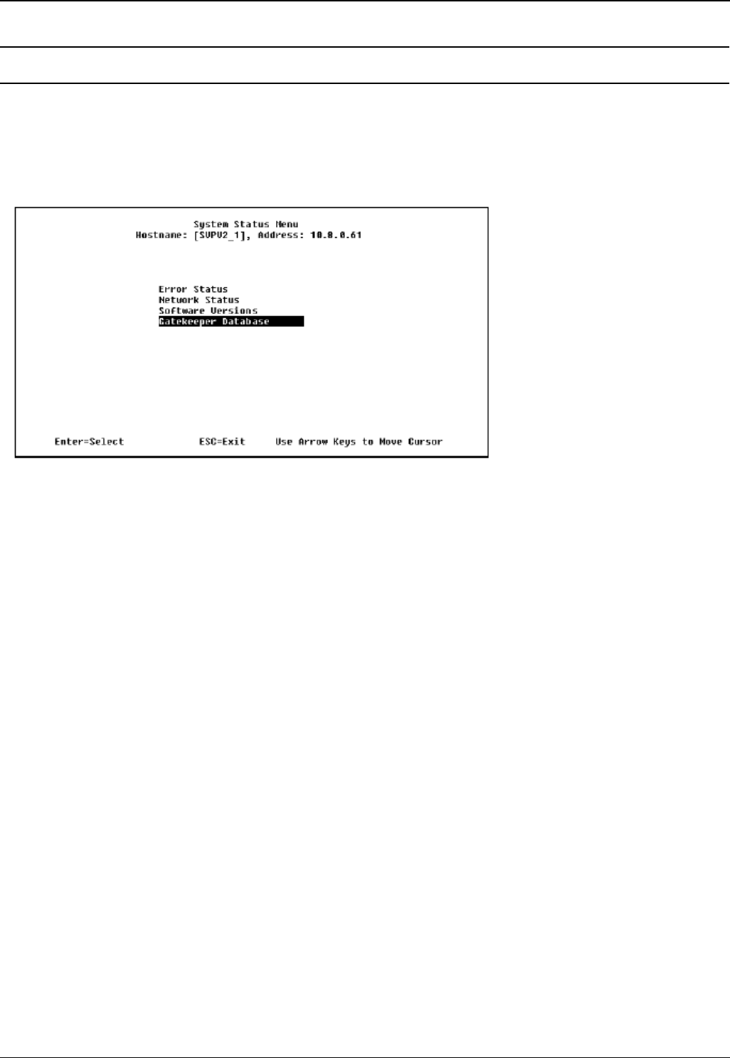
Wireless Installation and Configuration Guide Page 57
IP Office [15-601082] Issue [1] (1 June 2006)
Troubleshooting
AVPP Troubleshooting
Overview
Information about system alarms and network status are displayed on various screens, which can be
accessed via the System Status Menu. From the main menu, select System Status. A screen similar
to the following is displayed:
The screen displays:
Error Status - displays alarm and error message information.
Network Status - displays information about the Ethernet network to which the AVPP is
connected.
Software Versions - lists the software version for the Avaya component.
Gatekeeper Database - not used.
Options on the System Status menu provide a window into the real time operation of the components of
the system. Use this data to determine system function and to troubleshoot areas that may be
experiencing problems.
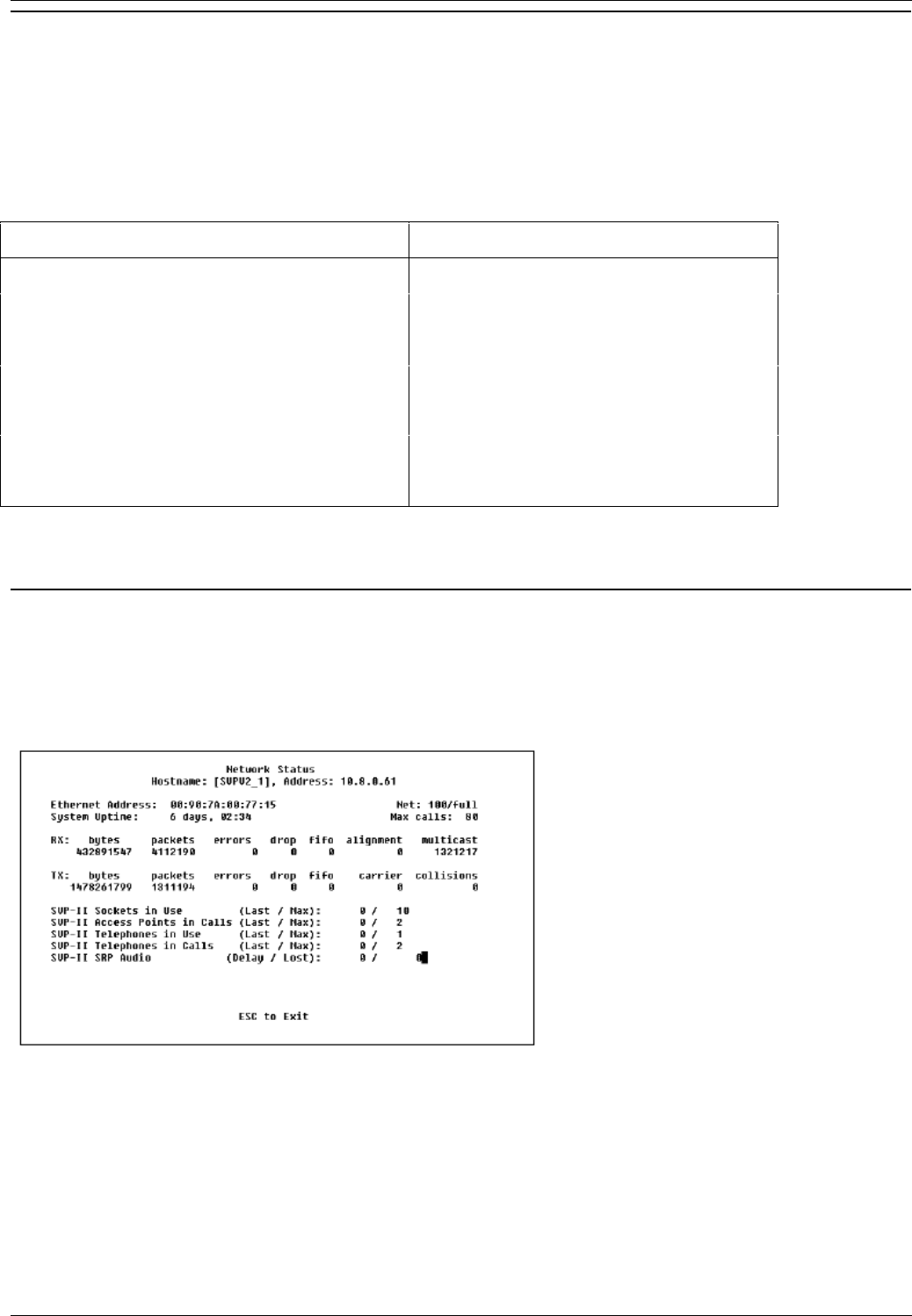
Wireless Installation and Configuration Guide
Wireless Installation and Configuration Guide Page 58
IP Office [15-601082] Issue [1] (1 June 2006)
Error Status
The Error Status screen displays any alarms that indicate some system malfunction. Some of these
alarms are easily remedied and others require a call to Avaya's Customer Support.
From the System Status Menu, select Error Status. The screen displays active alarms on the AVPP.
The following table displays the list of alarms and a description of the action to take to eliminate the
alarm:
Alarm Text Action
Maximum payload usage reached Reduce usage, clear alarm
Maximum telephone usage reached Reduce usage, clear alarm
Maximum access point usage reached Reduce usage, clear alarm
Maximum call usage reached Reduce usage, clear alarm
SRP audio delayed Reduce usage, clear alarm
SRP audio lost Reduce usage, clear alarm
No IP address Configure an IP address
To clear all clearable alarms, press C.
Network Status
The AVPP is connected to the Ethernet network, referred to as the LAN or Local Area Network. The
information about that connection is provided through the Network Status screen.
From the System Status Menu, select Network Status. A screen similar to the following is displayed:

Troubleshooting
Wireless Installation and Configuration Guide Page 59
IP Office [15-601082] Issue [1] (1 June 2006)
The screen displays information about the Ethernet network which can help troubleshoot network
problems:
Ethernet Address - MAC address of the AVPP (hexadecimal).
System Uptime - the number of days, hours and minutes since the AVPP was last reset.
Net - the type of connection to the Ethernet switch currently being utilized.
Note
Data is transmitted over Avaya components by proprietary technology developed by
Avaya. The Avaya Radio Protocol (ARP) packets and bytes can be differentiated from
other types of transmissions and are used to evaluate system functioning by Avaya
customer support and engineering personnel.
RX - Ethernet statistics concerning the received packets during System Uptime.
bytes - bytes received.
packets - packets received.
errors - sum of all receive errors (long packet, short packet, CRC, overrun, alignment).
drop - packets dropped due to insufficient memory.
fifo - overrun occurred during reception.
alignment - nonoctet-aligned packets (number of bits NOT divisible by eight).
multicast - packets received with a broadcast or mulitcast destination address.
TX - Ethernet statistics concerning the transmitted packets during System Uptime.
bytes - bytes transmitted.
packets - packets transmitted.
errors - sum of all transmit errors (heartbeat, late collision, repeated collision, underrun,
carrier).
drop - packets dropped due to insufficient memory.
fifo - underrun occurred during transmission.
carrier - carrier lost during transmission.
collisions - packets deferred (delayed) due to collision.
SVP-II Access Points in Use - access points in use by wireless phones, either in standby or in a
call. 'Last' is current, 'Max' is the maximum number in use at one time.
SVP-II Access Points in Calls - access points with wireless phones in a call.
SVP-II Telephone in Use - wireless phone in standby or in a call.
SVP-II Telephone in Calls - wireless phone in a call.
SVP-II ARP Audio (Delay) - ARP audio packets whose transmission was momentarily delayed.
SVP-II ARP Audio (Lost) - ARP audio packets dropped due to insufficient memory resources.
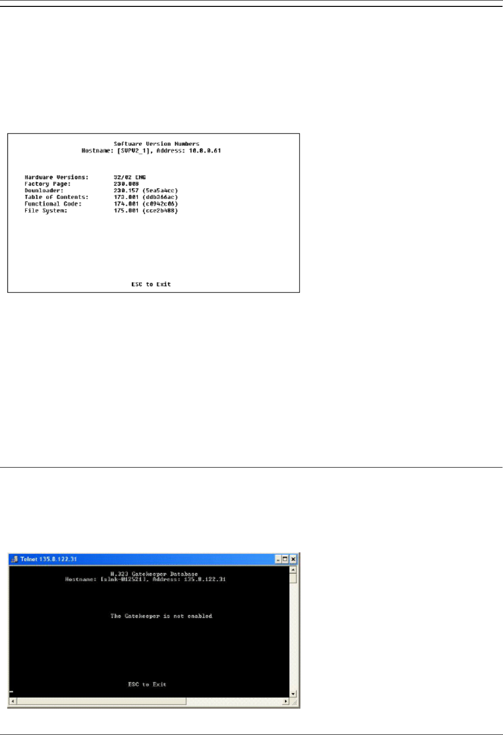
Wireless Installation and Configuration Guide
Wireless Installation and Configuration Guide Page 60
IP Office [15-601082] Issue [1] (1 June 2006)
Software Version
The AVPP and wireless phones, utilize Avaya's proprietary software that is controlled and maintained
through software versions. The Software Version screen provides information about the version
currently running on the AVPP. This information will help you determine if you are running the most
recent version and will assist Avaya engineering and/or customer support in troubleshooting software
problems.
From the System Status Menu, select Software Version. A screen similar to the following is displayed:
Note
The software versions on your system will be different from the versions displayed in the above
sample screen.
The 170 series software is required in certain IP environments.
Name Major Version Number Filename
Table of Contents 173 svp100.toc
Functional Code 174 zvmlinux
File System 175 flashfs
Gatekeeper Database
The Gatekeeper Database screen lists the registered extension numbers and the IP address currently
being used by each extension. The Gatekeeper is not enabled. If this option is selected a screen similar
to the following is displayed:

Troubleshooting
Wireless Installation and Configuration Guide Page 61
IP Office [15-601082] Issue [1] (1 June 2006)
Wireless Phone Troubleshooting
Introduction
Wireless phones can exhibit transmission problems in several ways. They can cease functioning
properly, display error messages, or display incorrect data. When using and troubleshooting wireless
phones, consider the problem sources described in this section, to determine the best method of
approaching any specific situation.
Access Point Problems
Most, but not all, wireless phone audio problems have to do with access point range, positioning and
capacity. Performing a Site Survey as described in the Setup and Maintenance document can isolate the
access point causing these types of problems. If the wireless phone itself is suspected, conduct a
parallel Site Survey with a wireless phone that is known to be properly functioning.
In Range/Out of Range
Service will be disrupted if a user moves outside the area covered by the wireless LAN access points.
Service is restored if the user moves back within range. If a call drops because a user moves out of
range, the wireless phone will recover the call if the user moves back into range within a few seconds.
Capacity
In areas of heavy use, the call capacity of a particular access point may be filled. If this happens, the
user will hear three chirps from the wireless phone. The user can wait until another user terminates a
call, or move within range of another access point and try the call again. If a user is on a call and moves
into an area where capacity is full, the system attempts to find another access point. Due to range
limitations, this may be the same as moving out of range.
Transmission Obstructions
Prior to system installation, the best location for access points for optimum transmission coverage was
determined. However, small pockets of obstruction may still be present, or obstructions may be
introduced into the facility after system installation. This loss of service can be restored by moving out of
the obstructed area, or by adding access points.
Configuration Problems
Certain problems are associated with improper configuration of either IP Office or the wireless phone.
Configuration problems are generally corrected by changing the configuration on IP Office or on the
wireless phone. See IP Office Configuration and Wireless Phone Configuration for specific configuration
steps.
There may also be incorrect programming of the access point. See the Configuration Note for the access
point in use at the site.
If IP Office registration fails, note any error messages on the display including which line icons are
active. This information will help with the problem resolution.

Wireless Installation and Configuration Guide
Wireless Installation and Configuration Guide Page 62
IP Office [15-601082] Issue [1] (1 June 2006)
Wireless Phone Status Messages
Wireless phone status messages provide information about the wireless phone's communication with the
access point and host phone system. The following table summarizes the status messages, in
alphabetical order.
Message Description Action
3 chirps The wireless phone is not able
to communicate with the best
access point, probably
because that access point has
no bandwidth available.
None. This is only a warning, the
call will handoff to the best access
point once it becomes available.
ASSERTxxx.c
Line yyy The wireless phone has
detected a fault from which it
cannot recover.
Record the error code so it can be
reported. Turn the wireless phone
off then on again. If error persists,
try registering a different wireless
phone to the phone port. If error
still persists, contact Technical
Support and repeat the error.
Bad Config Some needed configuration
parameter has not been set. Check all required wireless phone
configuration parameters for valid
settings.
Bad ESSID The wireless phone is
configured for “static ESSID”
(as opposed to “Learn once”
or “Learn always” and no ESS
ID has been entered.
Enter an ESSID in the
configuration settings or change to
one of the "Learn” modes.
Charging... The wireless phone is
charging in the desktop
charger.
No action needed.
Charge Complete The wireless phone is now
fully charged. No action needed.
Checking Code The wireless phone is
contacting the TFTP Server to
determine if it has a newer
version of software that should
be downloaded.
None, this message should only
last for approximately one second.
If message remains displayed,
power off and contact customer
support for a replacement phone.
Checking DHCP IP The wireless phone is
retrieving DHCP information
from the DHCP server.
None. This is information only.
CRC Code Error The software which has been
TFTP downloaded has a bad
redundancy code check.
Try the download again, it is
possible the software was
corrupted during download. If the
error repeats, check that the
download image on the TFTP
server is not corrupted.
Code Mismatch! The software loaded into the
wireless phone is incorrect for
this model phone
Replace the software image on
the TFTP server with software that
is correct for the phone model.

Troubleshooting
Wireless Installation and Configuration Guide Page 63
IP Office [15-601082] Issue [1] (1 June 2006)
DHCP Error 1 The wireless phone cannot locate
a DHCP server. It will try every 4
seconds until a server is located.
DHCP Error 2 The wireless phone has not
received a response from the
server for a request to an IP
address. It will retry until a server
is found.
DHCP Error 3 The server refuses to lease the
wireless phone an IP address. It
will keep trying.
DHCP Error (1-4)
DHCP Error 4 The server offered the wireless
phone a lease that is too short.
The minimum lease time is 10
minutes but Spectralink
recommend at least one hour
minimum lease time. The wireless
phone will stop trying. Re-
configure the server and power
cycle the wireless phone.
DHCP Lease Exp The wireless phone’s DHCP
lease has expired, and the call
(if any)cannot continue.
The wireless phone failed to
renew its DHCP lease, either
because the DHCP server is not
running, or because the
configuration has been changed
by the administrator. The wireless
phone will attempt to negotiate a
new lease, which will either work,
or change to one of the above
DHCP errors (1-4).
DHCP NACK error A NACK (Negative
ACKnowledge)was received
from the DHCP server.
The DHCP lease currently in use
by the wireless phone is no longer
valid, which forces the wireless
phone to restart. This problem
should resolve itself on the restart.
If it does not, the problem is in the
DHCP server.
DO NOT POWER
OFF The wireless phone is in a
critical section of the software
update.
None. Do not remove the battery
or attempt to power off the phone
while this is displayed. Doing so
may require the phone to be
returned to Avaya to be
recovered.
Duplicate IP The wireless phone has
detected another device with
its same IP address.
If using DHCP, check that the
DHCP server is properly
configured to avoid duplicate
addresses. If using static IP,
check that the wireless phone was
assigned a unique address.
Erase Failed Download process failed to
erase the memory in the
wireless phone.
Operation will retry but may
eventually report the error “int.
error: 0F” Power cycle the phone.

Wireless Installation and Configuration Guide
Wireless Installation and Configuration Guide Page 64
IP Office [15-601082] Issue [1] (1 June 2006)
Erasing Memory The wireless phone has
determined that a download
should occur and is erasing
the current software from
memory.
None. When the progress bar fills
the display line the erase
operation is complete.
Extension Error Displayed for 5 seconds when
all of the IP Offices contacted
indicate that they do not
recognize the current
extension as valid.
The user will be asked to enter a
valid extension and password.
Extension in use The phone is trying to register
with an extension that is
already registered on IP
Office.
See Avaya IP Office Integration
Factors.
Incompatible The switch is rejecting the
software version presented by
the phone.
If this condition persists, contact
the system administrator.
Initializing... The wireless phone is
performing power on
initialization.
None. This is information only.
Internal Err. ## The wireless phone has
detected a fault from which it
cannot recover.
Record the error code so that it
can be reported. Turn the wireless
phone off and then on again. If the
error persists, try registering a
different wireless phone to the
phone port. If error still persists,
contact Avaya Technical Support
and report the error.
Low Battery, and
beep
Low battery On call: the battery icon displays
and a soft beep will be heard
when the user is on the wireless
phone and the battery charge is
low. User has 15–30 minutes of
battery life left.
Not on call: The battery icon
displays whenever the battery
pack charge is low The message
Low Battery and a beep sound
indicate a critically low battery
charge when user is not on the
wireless phone. The wireless
phone will not work until the
battery pack is charged.
Multiple GW Res More than one SVP server
has responded. Caused by two or more wireless
phones sharing the same IP
address. Assign unique IP
addresses to each wireless
phone.
Network Busy All access points are full or
busy. Try calling again later.

Troubleshooting
Wireless Installation and Configuration Guide Page 65
IP Office [15-601082] Issue [1] (1 June 2006)
The wireless phone is not
administered on IP Office. The wireless phone is not properly
configured. Verify that the
extension and password in the
wireless phone match those
administered on the IP Office unit.
IP Office is not working. Verify that IP Office is operational.
If so, follow standard
troubleshooting procedures for IP
Office.
No LAN connection at the
access point or the IP Office. Verify the IP Office connection to
LAN and all access points.
No IP Office
or
No IP Office
(when apparently
valid IP, but no
response to the
GRQ/RRQ process)
The No IP Office
message may
include an error
indication
The wireless phone cannot
locate the IP Office. IP address configuration of IP
Office is wrong or missing.
No Host IP The wireless phone is
configured for “static IP” (as
opposed to “use DHCP”) and
no valid host IP address (the
wireless phone’s IP address)
has been entered.
Enter a valid IP address in the
configuration settings or change to
“use DHCP”.
No IP Address Invalid IP. Check the IP address in the
configuration settings or change to
"use DHCP".
Cannot authenticate/associate
with access point. Verify the access point
configuration
No Net Access
Incorrect WEP settings. Verify that all the WEP settings in
the wireless phone, match those
in the access points.
This indicates on of the
following:
No radio link Verify that the access point is
turned on.
No ESSID - Autolearn not
supported (or) incorrect
ESSID.
Verify that the ESSID of the
wireless LAN and enter or
Autolearn it again if required.
No Net Found
Out of range Try getting close to an access
point. Check to see if other
wireless phones are working
within the same range of an
access point. If so, check the
ESSID of this wireless phone.
No Reg Domain Regulatory Domain not set. Configure the Regulatory Domain
of the wireless phone.
No AVPP IP The wireless phone is
configured for “static IP” (as
opposed to “use DHCP”) and
no valid AVPP address has
been entered.
Enter a valid AVPP IP address in
the configuration setting or change
to "use DHCP".

Wireless Installation and Configuration Guide
Wireless Installation and Configuration Guide Page 66
IP Office [15-601082] Issue [1] (1 June 2006)
No AVPP
Response The AVPP is not responding
to requests from the wireless
phone.
This may be caused by bad radio
reception or a problem with AVPP.
The wireless phone will keep
trying to fix the problem for 20
seconds, and the message may
clear by itself. If it does not, the
wireless phone will restart. Report
this problem to the system
administrator if it keeps
happening.
No AVPP Server The wireless phone cannot
locate AVPP. IP address configuration of the
AVPP is wrong or missing.
AVPP is not working. Check error status screen on the
AVPP.
No LAN connection at the
AVPP. Verify the AVPP connection to
LAN.
Not Installed! A required software
component is missing. Check that all required software
files are on the TFTP server, if
over-the-air downloading is being
used. If the error repeats, contact
Avaya Technical Support.
Password Error The phone is not encrypting
the challenge string correctly.
This indicates that the
password set in the phone
disagrees with the password
administered in IP Office.
Enter the correct password in the
phone.
Press End Call Your call has ended. To return to standby mode, press
Power Off/End Call
Restarting... The wireless phone is in the
process of rebooting. There
will be a 20 second delay in
an attempt to let potential
network/system errors clear.
None.
Retry/Restart The wireless phone is waiting
for user input, prior to retrying
the registration process or
restarting after a delay.
See Avaya IP Office Integration
Factors.
Select License The correct protocol has not
been selected from the license
set.
Using the administrative menus,
select one license from the set to
allow the phone to download the
appropriate software.
Server Busy The wireless phone is
attempting to download from a
TFTP server that is busy
downloading other devices
and refusing additional
downloads.
None, the wireless phone will
automatically retry the download
every few seconds.

Troubleshooting
Wireless Installation and Configuration Guide Page 67
IP Office [15-601082] Issue [1] (1 June 2006)
AVPP Service Rej. The AVPP has rejected a
request from the wireless
phone.
The wireless phone will restart
and attempt to re-register with the
AVPP, which should fix the
problem. Report this to your
system administrator if it keeps
happening.
System Busy AVPP is busy or out of
resources. All call paths are in use, try calling
again in a few minutes.
System Error An internal failure has
occurred in AVPP. If this condition persists, contact
the system administrator.
System Locked
(with Busy Tone) AVPP is locked. Try calling again later.
TFTP
ERROR(x):yy A failure has occurred during
a TFTP software download.
(x) = The file number which
was being downloaded; yy is
an error code describing the
particular failure. Possible
error codes are:
01 = TFTP server did not find
the requested file.
02 = Access violation
(reported from TFTP server).
07 = TFTP server reported
"No such user" error.
81 = File put into memory did
not CRC.
FF = Timeout error. TFTP
server did not respond within
a specified period of time.
Error code 01, 02 or 07 - check
the TFTP server configuration.
Error code 81 - the wireless phone
will attempt to download the file
again.
For other messages, power off the
wireless phone, then turn it on
again to retry the download. If the
error repeats, note it and contact
Technical Support.
Trying
xxx.xxx.xxx.xxx The phone is attempting to
register with IP Office at IP
xxx.xxx.xxx.xxx
None. The display is a progress
indicator and may not appear long
enough to recognize during a
normal check-in.
Undefined Error The system is rejecting the
registration of the wireless
phone with an unrecognized
error code.
If this condition persists, contact
the Avaya system administrator.
Updating Code... The wireless phone is
downloading new software
into memory. The number
icons at the bottom of the
display indicate which file
number is currently being
downloaded.
None. When the progress bar fills
the display line, the update
operation is complete on that file.
Updating... The wireless phone is
internally updating its software
images.
None. The wireless phone may do
this briefly after a download. This
is information only.

Wireless Installation and Configuration Guide
Wireless Installation and Configuration Guide Page 68
IP Office [15-601082] Issue [1] (1 June 2006)
Waiting... The wireless phone has
attempted some operation
several times and failed.
None. The wireless phone is
waiting for a specific period of time
before attempting that operation
again.
Wrong Code Type Internal consistency check
failure. Check that the license type is set
to 9 and that the slnk_cfg.cfg file
indicates the proper bode .bin.
Wrong Set Type The set type administered on
IP Office disagrees with the
set type for the wireless
phone.
Make sure that the set type 4606
is used for the wireless phone.
(No message
shown) There is no voice path. Verify that the CODEC is G.711.
(No message
shown) Messages are left at the
principal station but the MSG
icon is not lit on the wireless
phone.
Verify that "Message Lamp Ext",
on the station form for the wireless
phone, is set to the extension of
the principal station.

Wireless Installation and Configuration Guide Page 69
IP Office [15-601082] Issue [1] (1 June 2006)
Index
A
about this guide..........................................................2
access point.........................................................9, 61
admin menu .............................................................34
admin PW ................................................................43
assigning functions ..................................................49
associated station ....................................................23
AVPP
adding .................................................................22
connecting ..........................................................14
front panel.............................................................4
locating ...............................................................13
master.................................................................22
multiple .................................................................4
network status.....................................................58
password ............................................................21
removing .............................................................22
upgrading............................................................56
AVPP .......................................................................31
AVPP .......................................................................37
B
button programming.................................................23
C
call server IP ............................................................37
capacity....................................................................61
Cisco FSR................................................................41
configuration
associated station...............................................23
AVPP ..................................................................31
network ...............................................................16
problems.............................................................61
process ...............................................................48
QoS.....................................................................20
standalone station...............................................23
system ................................................................30
coverage ..................................................................51
D
data rates.................................................................52
dBm..........................................................................52
declaration of conformity............................................1
DHCP.................................................................23, 37
display......................................................................12
DNS .........................................................................23
E
error status...............................................................58
ESSID ......................................................................39
ethernet switch...........................................................9
extension..................................................................44
G
gatekeeper...............................................................60
I
in range/out of range................................................61
IP address................................................................37
IP Office Manager ....................................................23
L
license management................................................40
M
messages...........................................................54, 62
O
OAI.....................................................................37, 42
overview.....................................................................7
P
password..................................................................44
R
required materials ....................................................13
requirements ........................................................7, 48
restore defaults ........................................................40
retry/restart...............................................................23
S
security.....................................................................41
shielded cables ..........................................................3
site certification ........................................................51
site survey mode......................................................40
software version.......................................................60
standalone station....................................................23
SVPP-II ..............................................................15, 18
system
components ..........................................................9
configuration .......................................................30
status ..................................................................57
T
testing ......................................................................50
TFTP ..............................................................9, 23, 37
troubleshooting
coverage issues..................................................51
U
upgrading .................................................................54
user-defined preferences.........................................44
V
voice messaging ......................................................23
voice priority processor..............................................9
W
WEP.........................................................................41
wireless phone
certification..........................................................51
display.................................................................12
installation and configuration ..............................31
IP.........................................................................37
specifications ........................................................8
status messages.................................................62
testing .................................................................50
upgrading............................................................54

Wireless Installation and Configuration Guide
Wireless Installation and Configuration Guide Page 70
IP Office [15-601082] Issue [1] (1 June 2006)
Performance figures and data quoted in this document are typical, and must be specifically
confirmed in writing by Avaya before they become applicable to any particular order or contract.
The company reserves the right to make alterations or amendments to the detailed
specifications at its discretion. The publication of information in this document does not imply
freedom from patent or other protective rights of Avaya or others.
Intellectual property related to this product (including trademarks) and registered to Lucent
Technologies have been transferred or licensed to Avaya.
All trademarks identified by the ® or ™ are registered trademarks or trademarks, respectively,
of Avaya Inc. All other trademarks are the property of their respective owners.
This document contains proprietary information of Avaya and is not to be disclosed or used
except in accordance with applicable agreements.
Any comments or suggestions regarding this document should be sent to
"wgctechpubs@avaya.com".
© 2006 Avaya Inc. All rights reserved.
Avaya
Unit 1, Sterling Court
15 - 21 Mundells
Welwyn Garden City
Hertfordshire
AL7 1LZ
England
Tel: +44 (0) 1707 392200
Fax: +44 (0) 1707 376933
Web: http://www.avaya.com/ipoffice/knowledgebase
