Avaya Vf 3000 Users Manual Application Notes
VF 3000 to the manual fcb9aed2-d66d-4805-9d2e-1436bcf10354
2014-12-13
: Avaya Avaya-Vf-3000-Users-Manual-122158 avaya-vf-3000-users-manual-122158 avaya pdf
Open the PDF directly: View PDF ![]() .
.
Page Count: 61

Avaya Solution & Interoperability Test Lab
Avaya Hosted IP Telephony R3.0 Solution LSP
Configuration with the Juniper VF 3000 SBC – Issue 1.0
Abstract
These Application Notes describe the configuration of Avaya Communication Manager,
Juniper NetScreen Firewall and Juniper VF 3000 Session Border Controller (SBC) and other
network components in an Avaya Hosted IP Telephony R3.0 Local Survivable Processor
(LSP) environment. These Application Notes were written at the request of the Avaya Hosted
Solutions team.
TC; Reviewed:
PV 04/24/2006 Avaya – Proprietary
Use as authorized only pursuant to your signed agreement or
Avaya policy. No other disclosure is permitted or authorized.
1 of 61
HT3-LSP-VF.doc
TC; Reviewed:
PV 04/24/2006 Avaya – Proprietary
Use as authorized only pursuant to your signed agreement or
Avaya policy. No other disclosure is permitted or authorized.
2 of 61
HT3-LSP-VF.doc
Table of Contents
1. Introduction............................................................................................................................. 3
2. Background............................................................................................................................. 3
2.1. On Demand Solutions..................................................................................................... 3
2.2. Including LSPs in the Solution....................................................................................... 6
3. Configuration Overview ......................................................................................................... 8
3.1. Private-Public-Private Architecture................................................................................ 9
3.2. Private-Private Architecture............................................................................................ 9
3.3. Private-Public-Public architecture ................................................................................ 10
4. Equipment and Software Validated ...................................................................................... 11
5. Avaya HIPT R3.0 Environment............................................................................................ 12
5.1. Service Provider Data Center........................................................................................ 13
5.2. MPLS Core ................................................................................................................... 13
5.3. Customer Enterprise Sites............................................................................................. 13
5.3.1. PC-LAN based (Private-Private) Avaya Communication Manager..................... 14
5.3.2. G650/C-LAN based (Private-Public-Private) Avaya Communication Manager.. 14
6. Avaya Hosted IP Telephony Release 3.0 LSP Configuration .............................................. 15
6.1. PC-LAN Configuration (Private-Private)..................................................................... 15
6.1.1. Configure Avaya Communication Manager......................................................... 15
6.1.2. Configure Avaya Local Survivable Processors (LSP).......................................... 18
6.1.3. Configuring the Juniper NetScreen-25 Firewall................................................... 20
6.1.4. Configure the Juniper VF 3000 SBC.................................................................... 35
6.2. G650/C-LAN Configuration (Private-Public-Private).................................................. 37
6.2.1. Configure Avaya Communication Manager......................................................... 37
6.2.2. Configure Avaya Local Survivable Processors (LSP).......................................... 40
6.2.3. Configuring the Juniper NetScreen-25 Firewall................................................... 42
6.2.4. Configure the Juniper VF 3000 SBC.................................................................... 54
6.2.5. Enterprise Customer Checkpoint Firewall Configuration .................................... 56
7. Verification ........................................................................................................................... 59
8. Conclusion ............................................................................................................................ 60
9. References............................................................................................................................. 60
10. Glossary ............................................................................................................................ 60
TC; Reviewed:
PV 04/24/2006 Avaya – Proprietary
Use as authorized only pursuant to your signed agreement or
Avaya policy. No other disclosure is permitted or authorized.
3 of 61
HT3-LSP-VF.doc
1. Introduction
These Application notes provide instructions on how to configure Local Survivable Processor
(LSP) with the Juniper VF 3000 SBC in an Avaya Hosted IP Telephony (HIPT) R3.0 Solution
Environment. The solution described in this document requires the addition of an extra network
element, a Network Address Translation (NAT) device at the edge of the service provider’s data
center if customers with LSPs are to be supported. This document covers the configuration of
the NAT device, as well as the other components of the solution.
2. Background
2.1. On Demand Solutions
The Session Border Controller (SBC) function is an essential component of the two Avaya On
Demand/Hosted offers. The base offers for the Avaya HIPT R3.0/3.1 and Hosted Contact Center
(HCC) R3.0 will make use of the Juniper VF 3000 SBC from the Juniper VF-Series product line.
The Juniper VF 3000 SBC provides the Application Layer Gateway (ALG) and Network
Address Translation (NAT) functions for the Avaya VoIP network components. The Juniper VF
3000 SBC is deployed at the service provider’s data center and is shared amongst multiple
enterprise customers. The Juniper VF 3000 SBC segregates incoming traffic from different
customers and forwards the traffic to the associated Avaya Communication Manager. All
communication from components (i.e. endpoints, and media gateways) that passes through the
Juniper VF 3000 SBC will appear to Avaya Communication Manager as having a Juniper VF
3000 SBC IP address. These components also see Avaya Communication Manager as having a
Juniper VF 3000 SBC IP address. The Juniper VF 3000 SBC acts as a proxy in both directions.
The side of the Juniper VF 3000 SBC that is exposed to the Wide Area Network (WAN) is often
referred to as the “outside” interface – the untrusted side. The other side, the “inside” interface,
is the trusted side and is exposed to Avaya Communication Manager and the data center
network.
Figure 1 shows the high-level network architecture for a typical Avaya On Demand/Hosted
solution. The data center is owned and operated by the service provider. In this case the hosts in
the data center are in a private address space owned and managed by the service provider. The
individual customer networks include Avaya G250, G350 and G700 H.248 Media Gateways and
H.323 phones at the enterprise sites. The media gateways may include a Local Survivable
Processor (LSP) to support local survivability. The enterprise site is characterized by a private
IP address space owned and managed by the enterprise customer. Although not shown in the
diagram, each enterprise customer could have multiple, diversely located sites, any or all of
which may have MGs and LSPs in addition to endpoints. The IP address spaces in these sites are
independent, and could overlap. Transport between the enterprise sites and the data center in this
example occurs over the public addressed WAN. A NAT function is therefore required at the
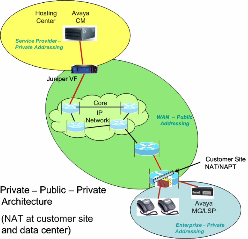
data center edge and at the edge of each enterprise site. Note that the Juniper VF 3000 SBC can
provide this NAT function.
Figure 1 - Private-Public-Private Architecture
Another method for WAN connectivity between the enterprise sites and the data center is via a
VPN configuration. Figure 2 illustrates this case. The Juniper VF 3000 SBC here must support
private-private NAT functionality, where the data center equipment is in a private IP address
space and the customer also uses a private IP address space. In this architecture, all the
enterprise customer’s sites, as well as the VPN that interconnects and extends to the edge of the
data center, are part of one private IP address space.
TC; Reviewed:
PV 04/24/2006 Avaya – Proprietary
Use as authorized only pursuant to your signed agreement or
Avaya policy. No other disclosure is permitted or authorized.
4 of 61
HT3-LSP-VF.doc
Next to the data center, the WAN edge router maps the incoming VPN traffic from the WAN
into an 802.1Q trunk. Each VPN maps to a different VLAN. Note that each VPN belongs to a
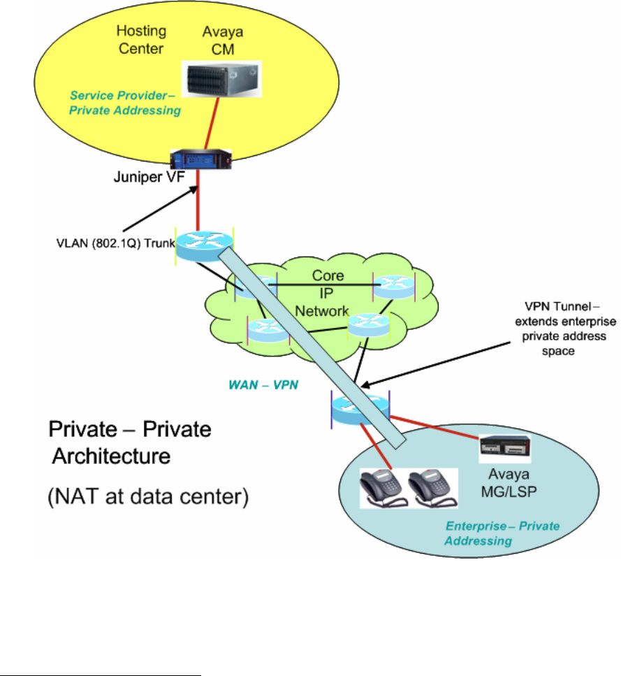
different enterprise customer. The Juniper VF 3000 SBC in the data center can make use of this
VLAN information to resolve overlapping IP address issues1. The Juniper VF 3000 SBC
segregates the access traffic into separate customer streams and routes the traffic to the
respective Avaya Communication Managers based on the destination IP address. Figure 2 shows
only one enterprise network containing only a single site, but multiple sites (and multiple
enterprises using multiple Avaya Communication Manager instances) should be considered the
norm.
Figure 2 - Private-Private Architecture
Initial deployments of the Avaya On Demand/Hosted solutions using the Juniper VF 3000 SBC
will use the architectures specified in Figure 1 or Figure 2. However, there is a third
TC; Reviewed:
PV 04/24/2006 Avaya – Proprietary
Use as authorized only pursuant to your signed agreement or
Avaya policy. No other disclosure is permitted or authorized.
5 of 61
HT3-LSP-VF.doc
1 Different enterprises could use overlapping IP private addresses.
TC; Reviewed:
PV 04/24/2006 Avaya – Proprietary
Use as authorized only pursuant to your signed agreement or
Avaya policy. No other disclosure is permitted or authorized.
6 of 61
HT3-LSP-VF.doc
architecture that may occur. This is similar to Figure 1, except that the data center uses public
IP addressing. There is no need for a NAT function between the WAN and the data center in this
case.
2.2. Including LSPs in the Solution
The Juniper VF 3000 SBC proxies the VoIP traffic for the components located at the enterprise
sites and presents all the VoIP traffic to the Avaya Communication Manager with the same IP
address – that of the Juniper VF 3000 SBC inside interface. The Juniper VF 3000 SBC maps all
enterprise IP addresses to this one IP address, and uses different transport layer port numbers to
distinguish between each IP address. The Juniper VF 3000 SBC is not capable of using multiple
inside IP addresses. This means that if all the LSPs in a given enterprise network are presented
to Avaya Communication Manager through the Juniper VF 3000 SBC, the LSPs will all have the
same IP address. However, Avaya Communication Manager is not designed to distinguish LSPs
by port number – but only by unique IP addresses. Therefore, with the current releases of Juniper
VF 3000 SBC and Avaya Communication Manager using the architectures shown in Figures 1-
2, LSP registration must bypass the Juniper VF 3000 SBC.
An Avaya Communication Manager Green feature (“SA8853 – Support of LSPs behind NAT”)
has been developed to allow the registration of LSPs to Avaya Communication Manager in a
way that does not require the ALG function of the Juniper VF 3000 SBC. Figure 3 depicts the
solution architecture when applied to the architecture shown in Figure 1. Note that a separate
NAT/FW device (FW is firewall) has been added to the edge of the data center for LSP-related
traffic only. Also, the NAT function for the LSP in the enterprise site is being handled differently
than for the other components there. A static NAT entry is needed for each LSP.
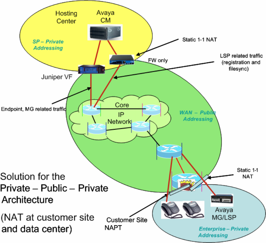
Figure 3 - Supporting LSPs in the Private-Public-Private Architecture
Figure 4 shows the architecture for a corresponding solution applied to the architecture of
Figure 2. As in Figure 3, an extra NAT/FW device has been placed at the data center edge. This
FW device must be VLAN supported in order to support overlapping address spaces for different
LSPs in different enterprises. However, unlike Figure 3, no changes are needed to the equipment
at the edge of the enterprise site since there is no change in address space at that point.
TC; Reviewed:
PV 04/24/2006 Avaya – Proprietary
Use as authorized only pursuant to your signed agreement or
Avaya policy. No other disclosure is permitted or authorized.
7 of 61
HT3-LSP-VF.doc
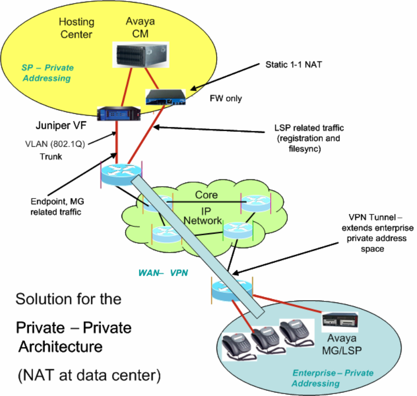
Figure 4 - Supporting LSPs in the Private-Private Architecture
3. Configuration Overview
This section gives a high-level overview of how to configure enterprise sites and data center
networks and how to administer the Avaya Communication Manager servers and LSPs for LSP
functionality to work in HIPT R3.0/3.1 and HCC R3.0 solutions. The basic configuration of the
solution without LSPs is assumed to already be in place. The remainder of this document will
provide the details for what is summarized here for the private-public-private and private-private
architectures. (The private-public-public architecture is expected to work as well, but has not
been certified.)
TC; Reviewed:
PV 04/24/2006 Avaya – Proprietary
Use as authorized only pursuant to your signed agreement or
Avaya policy. No other disclosure is permitted or authorized.
8 of 61
HT3-LSP-VF.doc

TC; Reviewed:
PV 04/24/2006 Avaya – Proprietary
Use as authorized only pursuant to your signed agreement or
Avaya policy. No other disclosure is permitted or authorized.
9 of 61
HT3-LSP-VF.doc
3.1. Private-Public-Private Architecture
In order to build components in Figure 3 use the following:
Enterprise site network configuration:
• On the FW/NAT device, configure a static 1-to-1 NAT mapping for each LSP.
Data center network configuration:
• Add a FW/NAT device, if one is not yet present. On the NAT device, configure static 1-
to-1 NAT mapping for each C-LAN/PE2 IP address.
• On the Juniper VF 3000 SBC, for each VF 3000 Session Routing Policy (SRP) used by a
set of IP phones, configure the native IP address of each LSP.
Avaya Communication Manager server administration:
• SA8853 Support of LSPs Behind Nat Green feature must be installed.
• Add two IP node names for each LSP, one for the statically mapped NAT WAN IP
address of each enterprise LSP and the other for its native private IP address.
• Administer the “lsp” form with the statically mapped NAT WAN IP address of each LSP.
• Administer the LSP list on the “ip-network-region” form, page 2 with the native (private)
IP address of each LSP.
LSP configuration:
• Enter the corresponding NAT WAN IP addresses of Avaya Communication Manager
servers/C-LANs/PEs in the “primary controller” and “C-LAN IP address of the primary
controller” fields on the LSP configuration web page.
3.2. Private-Private Architecture
In order to build components in Figure 4 use the following:
Enterprise site network configuration:
• None.
Data center network configuration:
• Add a VLAN supported FW/NAT device, if one is not yet present. On the FW/NAT
device, set up static NAT mappings so that enterprise site address space is converted to
data center address space, and vice versa, for IP addresses of LSPs in enterprise sites
address spaces and CM servers/C-LANs/PEs in the data center address space.
• On the Juniper VF 3000 SBC, for each VF session routing policy (SRP) used by a set of
IP phones, configure the native IP address of each LSP.
2 PE is an acronym for Processor Ethernet, an interface to CM that was formerly known as PC-LAN.
TC; Reviewed:
PV 04/24/2006 Avaya – Proprietary
Use as authorized only pursuant to your signed agreement or
Avaya policy. No other disclosure is permitted or authorized.
10 of 61
HT3-LSP-VF.doc
Avaya Communication Manager server administration:
• SA8853 Support of LSPs Behind NAT Green feature must be installed.
• Add two IP node names for each LSP, one for the statically mapped NAT IP address in
the data center IP address space of each enterprise LSP and the other for its native private
IP address.
• Administer the “lsp” form with the statically mapped NAT IP address in the data center
address space of each LSP.
• Administer the LSP list on the “ip-network-region” form, page 2 with the native (private)
IP address of each LSP.
LSP configuration:
• Enter the corresponding IP addresses of Avaya Communication Manager servers/C-
LANs/PEs in the enterprise site IP address space in the “primary controller” and “C-LAN
IP address of the primary controller” fields on the LSP configuration web page.
3.3. Private-Public-Public architecture
Note: This configuration was not validated.
Enterprise site network configuration:
• On the FW/NAT device, configure static 1-to-1 mapping for each LSP.
Data center network configuration:
• Provide a firewall to allow LSP registration and filesync traffic to pass (or reconfigure an
existing firewall).
• On the Juniper VF 3000 SBC, for each VF 3000 Session Routing Policy (SRP) used by a
set of IP phones, configure the native IP address of each LSP.
Avaya Communication Manager server administration:
• SA8853 Support of LSPs Behind Nat Green feature must be installed.
• Add two IP node names for each LSP. One for the statically mapped NAT WAN IP
address of each enterprise LSP and the other for its native private IP address.
• Administer the “lsp” form with the statically mapped NAT WAN IP address of each LSP.
• Administer the LSP list on the “ip-network-region” form, page 2 with the native (private)
IP address of each LSP.
LSP configuration:
• No change from traditional LSP configuration. Enter the corresponding IP addresses of
CM servers/C-LANs/PEs in the “primary controller” and “C-LAN IP address of the
primary controller” fields.

TC; Reviewed:
PV 04/24/2006 Avaya – Proprietary
Use as authorized only pursuant to your signed agreement or
Avaya policy. No other disclosure is permitted or authorized.
11 of 61
HT3-LSP-VF.doc
4. Equipment and Software Validated
This application note details one way to set up the LSP solution. The table below provides the
versions used in the verification of the described configurations.
Equipment Version
Avaya S8300B Media Servers (LSPs) HW4 FW 1
Avaya G650 Media Gateway
• TN799DP C-LAN
• TN2312AP IPSI
• TN2302AP Prowler
15
21
93
Avaya G700 Media Gateways
MGP
VoIP
DS1 MM710
4.1.4
24.21
54
13
Avaya G350 Media Gateway
DS1 MM710 24.21
13
Avaya 4610SW & 4620SW IP Telephones 2.2
Avaya 4602SW & 4601 IP Telephones 1.82
Avaya Secure Services Gateway 2.1
Avaya SBS3000 1.0
Juniper NetScreen-25 Firewall 4010(0) 5.1.0r3.0
Juniper VF 3000 SBC 6.0.3 (v603038G)
IBM Blade Center R1.0
Cisco 3660 Routers 12.2(8)T5
Cisco 3640 Routers 12.2(8)T4
Cisco 3620 Routers 12.2(12)
Cisco Catalyst 2948 Switches 4.5(9)
Cisco Catalyst 3500 Switches 12.0(5.2)XU
Table 1: Avaya Hosted IP Telephony Equipment
Software Version
Avaya IP SoftPhone 5.2.3.6
Avaya Communication Manager 3.0.1 (load 346)
Patch (Red Feature)
Microsoft DHCP Server Windows 2000 (SP4)
Checkpoint Firewall-1 (NG with Application Intelligence) R55 091
Avaya Integrated Management 3.0
IBM Director 4.2
Avaya Hosted Solution Element Manager (HSEM) 1.0
Table 2: Avaya Hosted IP Telephony Software
5. Avaya HIPT R3.0 Environment
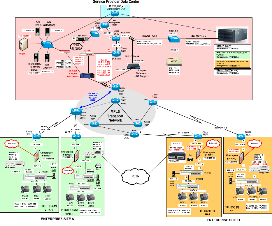
The overview of the HIPT R3.0 solution with LSP Support is shown in Figure 5.
Figure 5 – Avaya Hosted IP Telephony Release 3.0 LSP Solution
TC; Reviewed:
PV 04/24/2006 Avaya – Proprietary
Use as authorized only pursuant to your signed agreement or
Avaya policy. No other disclosure is permitted or authorized.
12 of 61
HT3-LSP-VF.doc
TC; Reviewed:
PV 04/24/2006 Avaya – Proprietary
Use as authorized only pursuant to your signed agreement or
Avaya policy. No other disclosure is permitted or authorized.
13 of 61
HT3-LSP-VF.doc
5.1. Service Provider Data Center
The Data Center simulates two customers, PC-LAN (Private-Private) and C-LAN (Private-
Public-Private). These customers each have their own image of Avaya Communication Manager.
These Avaya Communication Manager images both run on the same blade (HT1) in the Avaya
SBS3000 environment. The Data Center is privately addressed.
The PC-LAN based Avaya Communication Manager image has VPN based enterprise sites (A1
and A2).
The C-LAN based Avaya Communication Manager image has NAT based enterprise sites (B1
and B2).
One LSP is configured for each customer site. To configure additional LSP enterprise sites refer
to Section 6.1 for PC-LAN configuration and Section 6.2 for G650/C-LAN configuration.
The Data Center contains a network based Juniper VF 3000 SBC Session Border Controller. The
Juniper VF 3000 SBC provides H.323 and H.248 NAT processing to the WAN. The Juniper VF
3000 SBC also provides firewall functionality.
The Data Center also contains a Juniper NetScreen-25 Firewall VLAN supported device. The
NetScreen-25 Firewall provides NAT processing and firewall functionality to the WAN for the
LSP Solution.
5.2. MPLS Core
An MPLS core WAN network is used between the Data Center and the Enterprise sites. The
MPLS core network is composed of Cisco routers. MPLS IP VPNs are configured between the
Data Center and enterprise sites.
5.3. Customer Enterprise Sites
The Distributed Service Model enterprise sites access the Data Center via a public WAN. The
remote sites use local private IP addressing. The enterprise sites may use either private-to-private
VPN tunnels, or private-to-public NAT addressing, to access the Data Center via the public
WAN.
All of the enterprise sites contain a Checkpoint firewall for security. The Checkpoint also
provides IP NAT functionality for those sites that use private-to-public NAT addressing to
access the Data Center.
Enterprise sites contain Avaya Media Gateways with Local Survivable Processors (LSPs). Local
Survivable Processors (LSPs) provide local IP telephony in case connectivity to Avaya
TC; Reviewed:
PV 04/24/2006 Avaya – Proprietary
Use as authorized only pursuant to your signed agreement or
Avaya policy. No other disclosure is permitted or authorized.
14 of 61
HT3-LSP-VF.doc
Communication Manager in the Data Center is lost. All enterprise Local Survivable Processors
(LSPs) will achieve registration and File Sync via the data center NetScreen-25 Firewall device
to the appropriate Avaya Communication Manager image in the Data Center.
All enterprise site IP telephones register to the Juniper VF 3000 SBC in the Data Center (which
forwards the registration requests on to the appropriate Avaya Communication Manager image).
5.3.1. PC-LAN based (Private-Private) Avaya Communication Manager
Customer HTSITEB has remote enterprise sites (A1 and A2). These sites use local private
addressing, contain Avaya IP Telephones, and contain Avaya Media Gateways for local VoIP
resources. These sites will access the Data Center via a private-to-private VPN tunnel over the
WAN.
5.3.2. G650/C-LAN based (Private-Public-Private) Avaya Communication
Manager
Customer HTG650 has remote enterprise sites (B1 and B2). These sites use local private
addressing, contain Avaya IP Telephones, and contain Avaya Media Gateways for local VoIP
resources. These sites will access the Data Center via private-to-public NAT provided by the
Checkpoint firewall.
6. Avaya Hosted IP Telephony Release 3.0 LSP Configuration
6.1. PC-LAN Configuration (Private-Private)
6.1.1. Configure Avaya Communication Manager
The following Avaya Communication Manager provisioning is required to support the LSP
Configuration. This provisioning is performed via the SAT interface. In the following example,
the Avaya Communication Manager for LSP support is provisioned for site A1. Refer to [3] for
additional configuration information for Avaya Communication manager.
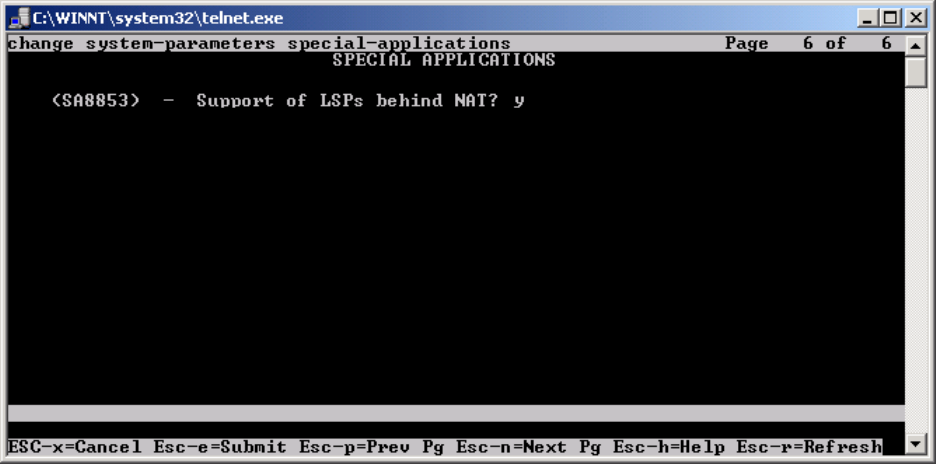
6.1.1.1. License Avaya Communication Manager
Avaya Communication Manager must be licensed to enable the special application “SA8853
Support of LSPs behind NAT”.
Step 1. Use the “change system-parameters special-applications” command to enable the
special application “SA8853 Support of LSPs behind NAT”. Select Esc-n to page for SA8853,
select y and submit the changes as shown in Figure 6.
Figure 6
Note: If this feature is installed as a patch (red feature) the feature will not show up on the Avaya
Communication Manager SA form as shown above. In a subsequent GA release, the feature
(green feature) will be part of the SA form, which can be enabled based on licensing.
TC; Reviewed:
PV 04/24/2006 Avaya – Proprietary
Use as authorized only pursuant to your signed agreement or
Avaya policy. No other disclosure is permitted or authorized.
15 of 61
HT3-LSP-VF.doc
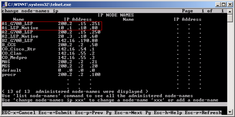
6.1.1.2. Configure Avaya Communication Manager for LSP Support
Step 1. Use the “change node-names ip” command to add the name and IP Address of the LSP
Native IP Address and static 1-to-1 NAT LSP IP address configured in the NetScreen-25
Firewall (Figure 20) to the node-names form shown in Figure 7. Submit the changes.
Figure 7
TC; Reviewed:
PV 04/24/2006 Avaya – Proprietary
Use as authorized only pursuant to your signed agreement or
Avaya policy. No other disclosure is permitted or authorized.
16 of 61
HT3-LSP-VF.doc
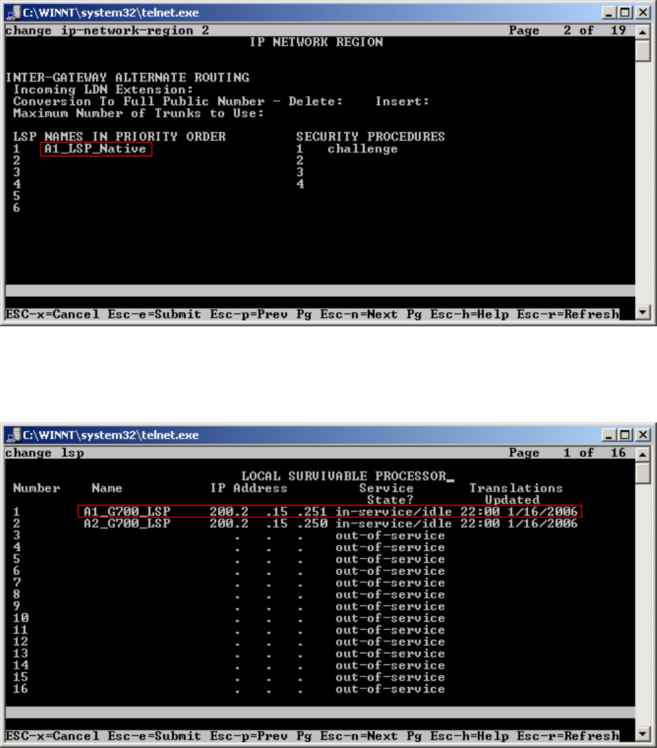
Step 2. Use the “change ip-network-region <region number>” command to add the LSP Native
IP Address to the appropriate Network Region shown in Figure 8. Submit the changes.
Figure 8
Step 3. Use the “change lsp” command to add the static 1-to-1 LSP IP address configured in the
NetScreen-25 Firewall (Figure 20) to the LSP form shown in Figure 9. Submit the changes.
Figure 9
TC; Reviewed:
PV 04/24/2006 Avaya – Proprietary
Use as authorized only pursuant to your signed agreement or
Avaya policy. No other disclosure is permitted or authorized.
17 of 61
HT3-LSP-VF.doc
TC; Reviewed:
PV 04/24/2006 Avaya – Proprietary
Use as authorized only pursuant to your signed agreement or
Avaya policy. No other disclosure is permitted or authorized.
18 of 61
HT3-LSP-VF.doc
6.1.2. Configure Avaya Local Survivable Processors (LSP)
Local Survivable Processors (LSP) are normally configured to register directly to Avaya
Communication Manager. In the Avaya Hosted IP Telephony environment, the LSPs must be
provisioned to register to Avaya Communication Manager via the static 1-to-1 NAT IP address
of the NetScreen-25 Firewall (Figure 18) serving the VPN enterprise site. This provisioning is
performed via the LSP web GUI interface. In the following example, the LSP for site A1 is
provisioned. Each LSP must be licensed to enable the special application “SA8853 Support of
LSPs behind NAT”. Refer to section 6.1.1.1 for instructions on the configuration.
1. Connect to the services port of the LSP and log into the web GUI.
2. From the GUI select “Launch Maintenance Web Interface”.
3. From the Maintenance page select “Configure Server” from the menu in the left hand
column.
4. Select “Continue”, and then “Continue” again.
5. Select “Configure Individual Services” and select “Continue”.
6. Select “Configure LSP” and the window shown in Figure 10 will open.
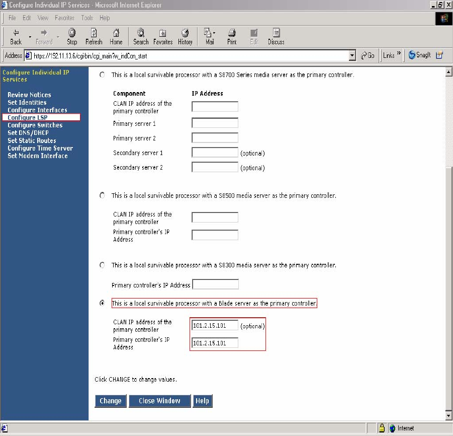
Figure 10 - LSP Configuration Web Page
7. Select “This is a local survivable processor with a Blade server as the primary
controller”. This option was selected for the Avaya SBS3000 shared blade server.
8. In the “CLAN IP address of the primary controller” and “Primary controller’s IP
address” fields, enter the IP address of the data center NetScreen-25 Firewall Untrusted side
Static 1-to-1 NAT IP address. In this example, the LSP is associated with IP address
101.2.15.101, which is the NAT IP address for the Avaya Communication Manager in the
Data Center and associated with Customer A1 VPN site.
TC; Reviewed:
PV 04/24/2006 Avaya – Proprietary
Use as authorized only pursuant to your signed agreement or
Avaya policy. No other disclosure is permitted or authorized.
19 of 61
HT3-LSP-VF.doc
6.1.3. Configuring the Juniper NetScreen-25 Firewall
This Section assumes that Juniper NetScreen-25 Firewall basic provisioning has been performed.
Refer to [1] for more information.
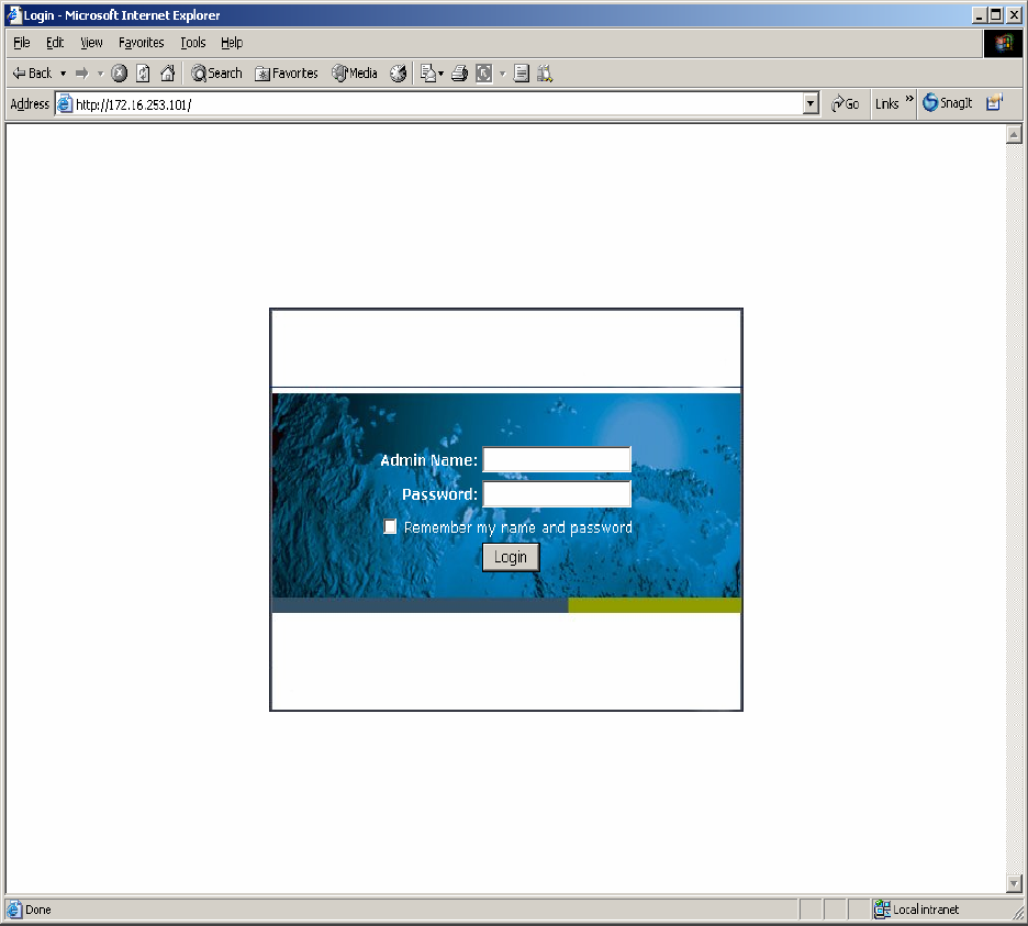
Step 1. From a PC, connect to the Juniper Networks NetScreen-25 Firewall using a web browser,
by typing https://<IP_address_NetScreen-25>. Login using a user name with administrative
credentials. See Figure 11.
Figure 11
TC; Reviewed:
PV 04/24/2006 Avaya – Proprietary
Use as authorized only pursuant to your signed agreement or
Avaya policy. No other disclosure is permitted or authorized.
20 of 61
HT3-LSP-VF.doc
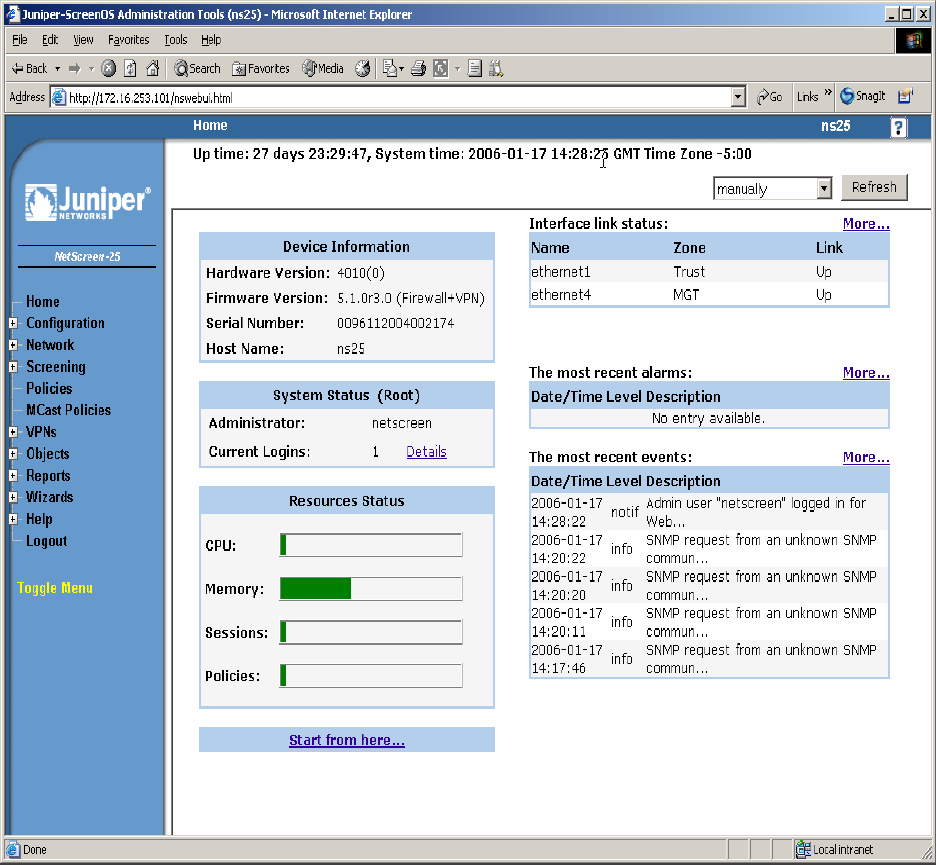
Step 2. The following WEB Admin screen appears upon successful login as shown in Figure 12.
Figure 12
Note: Virtual Router (trust-vr) has common configuration parameters for both PC-LAN (VR-A)
and G650/C-LAN (VR-B). The configuration for (trust-vr) settings are covered in this section.
TC; Reviewed:
PV 04/24/2006 Avaya – Proprietary
Use as authorized only pursuant to your signed agreement or
Avaya policy. No other disclosure is permitted or authorized.
21 of 61
HT3-LSP-VF.doc
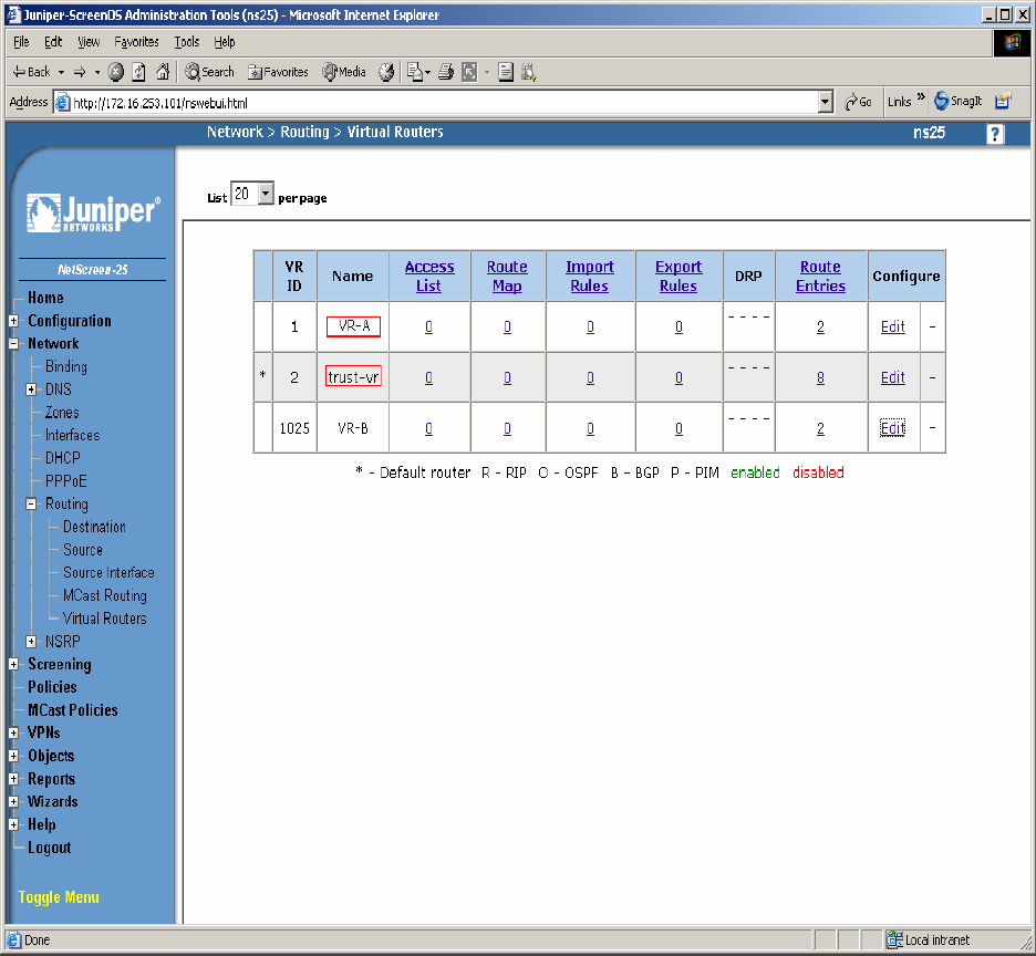
Step 3. Create a Virtual Router for enterprise site A (VR-A) and Data Center (trust-vr). From the
left pane click on Network Æ Routing Æ Virtual Routers. On the right pane, click the New
button on the top right hand corner to create a new Virtual Router. Set Virtual Router Name and
leave all other options as default values and click OK. Figure 13 shows the result of the
configured Virtual Router (VR-A) and (trust-vr). Refer to [1] for additional configuration
information.
Figure 13
TC; Reviewed:
PV 04/24/2006 Avaya – Proprietary
Use as authorized only pursuant to your signed agreement or
Avaya policy. No other disclosure is permitted or authorized.
22 of 61
HT3-LSP-VF.doc
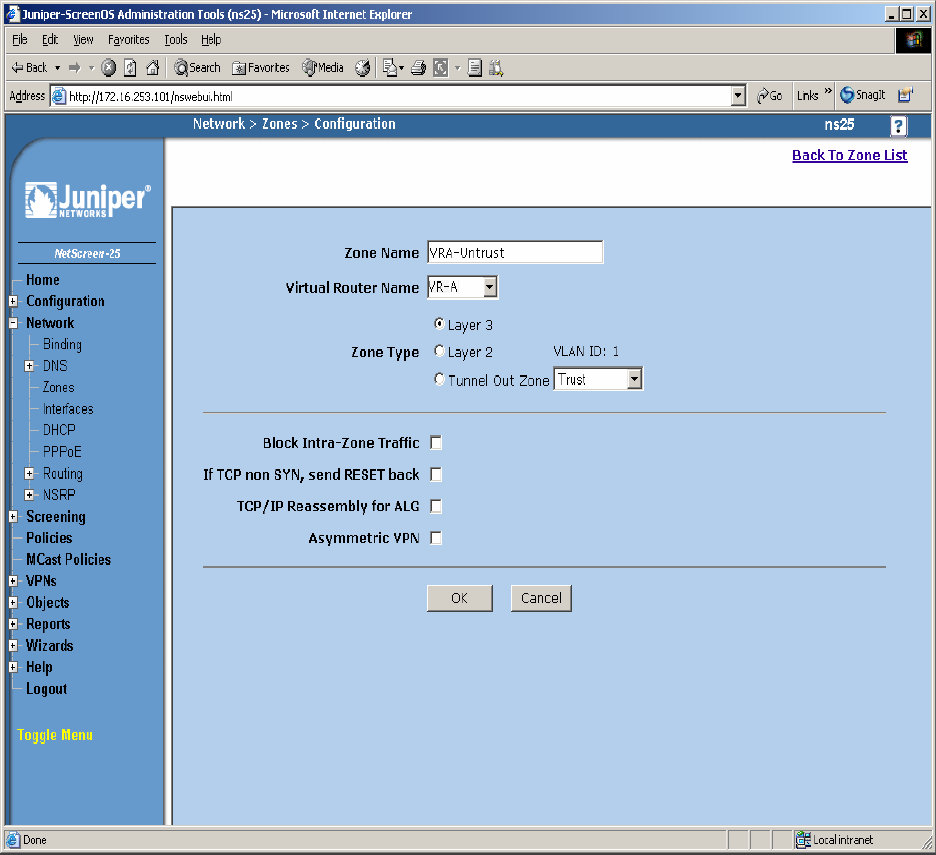
Step 4. Create security zones and assign the zone to the appropriate Virtual Routers. From the
left hand panel of the NetScreen-25 Firewall Web admin screen, click on Network Æ Zones.
From the right hand pane, click the New button to create a new zone. Create security zones for
the Virtual Router untrusted side (VR-A), zone name “VRA-Untrust” as shown in Figure 14 and
leave all other options as default values and click OK.
Figure 14
TC; Reviewed:
PV 04/24/2006 Avaya – Proprietary
Use as authorized only pursuant to your signed agreement or
Avaya policy. No other disclosure is permitted or authorized.
23 of 61
HT3-LSP-VF.doc
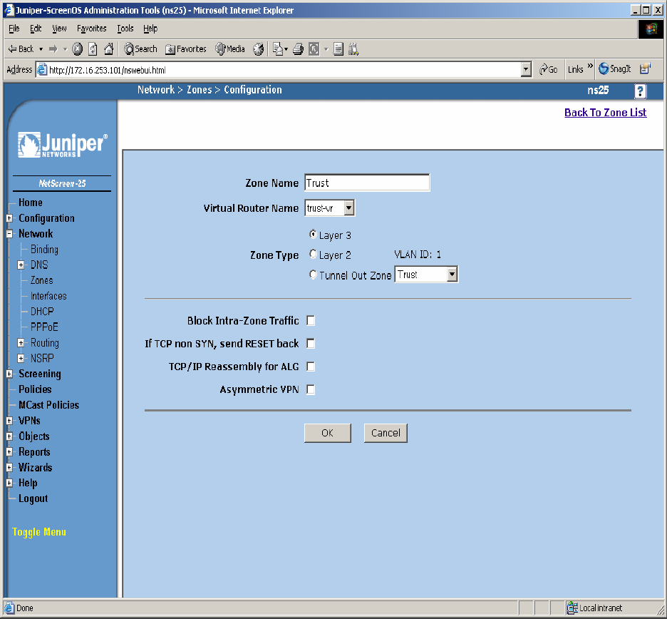
Step 5. Create security zones and assign the zone to the appropriate Virtual Routers. From the
left hand panel of the NetScreen-25 Firewall Web admin screen, click on Network Æ Zones.
From the right hand pane, click the New button to create a new zone. Create security zones for
the Virtual Router trusted side (trust-vr), zone name “Trust” as shown in Figure 15 and leave all
other options as default values and click OK.
Figure 15
TC; Reviewed:
PV 04/24/2006 Avaya – Proprietary
Use as authorized only pursuant to your signed agreement or
Avaya policy. No other disclosure is permitted or authorized.
24 of 61
HT3-LSP-VF.doc
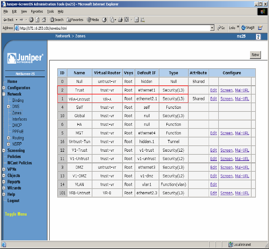
Step 6. Select Network Æ Zones in the left pane to view the list of configured zones as shown
in Figure 16. Additional Zones are shown that are not related to this Application Note.
Figure 16
TC; Reviewed:
PV 04/24/2006 Avaya – Proprietary
Use as authorized only pursuant to your signed agreement or
Avaya policy. No other disclosure is permitted or authorized.
25 of 61
HT3-LSP-VF.doc
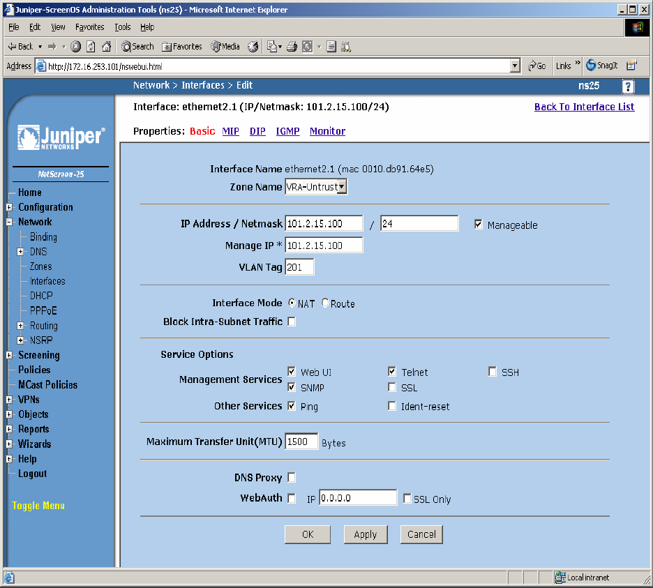
Step 7. Configure Interface with Mapped IP (MIP). The physical interface toward enterprise site
A is configured using sub-interfaces. The physical interface toward the Data Center does not use
sub-interfaces. From the NetScreen-25 Firewall Web Admin screen, click on Network Æ
Interfaces, and select Sub-IF on drop down menu then click the New button from the right hand
window pane. Create Sub-Interface ethernet2.1, zone VRA-Untrust. Configure Interface for
Zone Name, IP Address, VLAN Tag, Interface Mode and Service Options as shown in Figure 17
and leave all other options as default values and click OK.
Figure 17
TC; Reviewed:
PV 04/24/2006 Avaya – Proprietary
Use as authorized only pursuant to your signed agreement or
Avaya policy. No other disclosure is permitted or authorized.
26 of 61
HT3-LSP-VF.doc
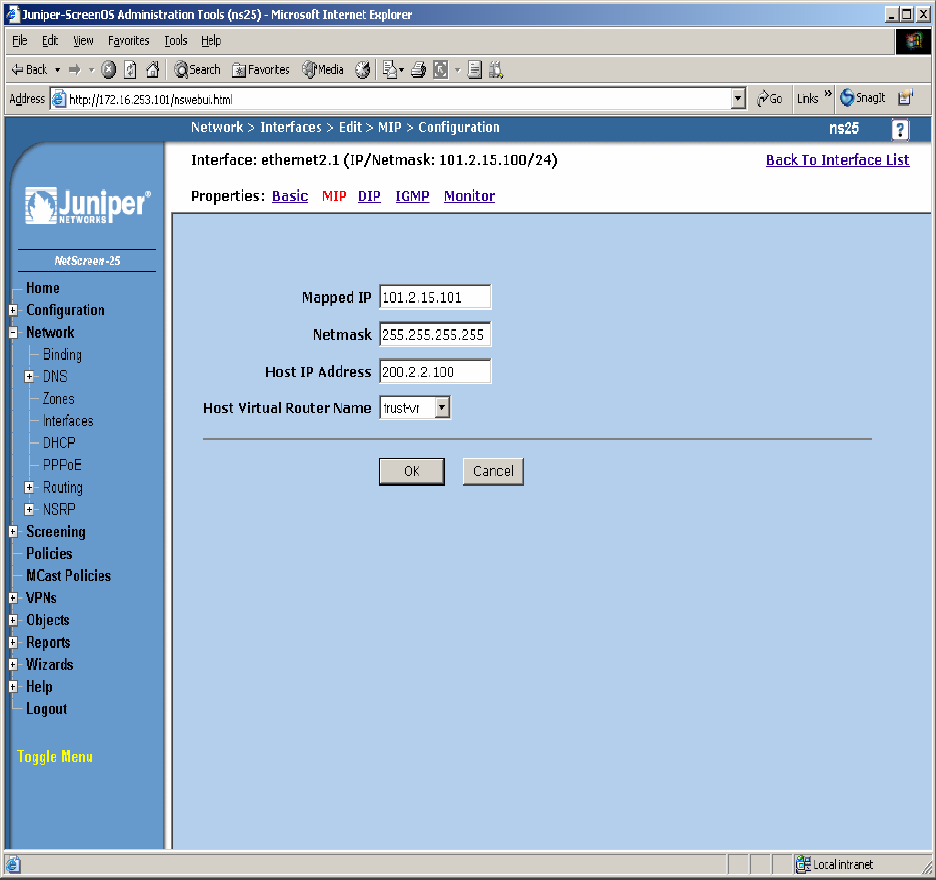
Step 8. Configure Sub-Interface ethernet2.1 MIP for LSP to Avaya Communication Manager
Static 1-to-1 NAT. From the NetScreen-25 Firewall Sub-IF screen, select MIP, and click the
New button from the right hand window pane. Configure MIP as shown in Figure 18 and click
OK.
Figure 18
TC; Reviewed:
PV 04/24/2006 Avaya – Proprietary
Use as authorized only pursuant to your signed agreement or
Avaya policy. No other disclosure is permitted or authorized.
27 of 61
HT3-LSP-VF.doc
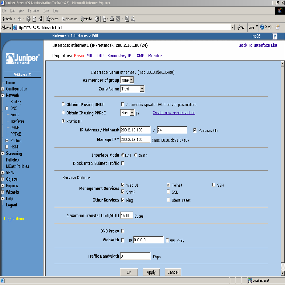
Step 9. Configure Interface with Mapped IP (MIP). The physical interface toward the Data
Center does not use sub-interfaces. From the NetScreen-25 Firewall Web Admin screen, click on
Network Æ Interfaces and then click the New button from the right hand window pane. Create
Interface ethernet1, zone Trust. Configure Interface for Zone Name, IP Address, Interface Mode
and Service Options as shown in Figure 19 and leave all other options as default value and click
OK.
Figure 19
TC; Reviewed:
PV 04/24/2006 Avaya – Proprietary
Use as authorized only pursuant to your signed agreement or
Avaya policy. No other disclosure is permitted or authorized.
28 of 61
HT3-LSP-VF.doc
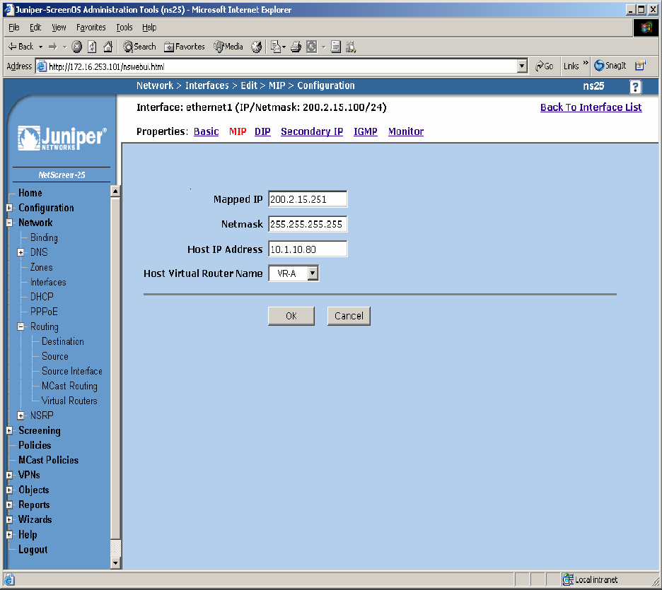
Step 10. Configure Sub-Interface ethernet1 MIP for Avaya Communication Manager to LSP
Static 1-to-1 NAT. From the NetScreen-25 Firewall Sub-IF screen, select MIP, and click the
New button from the right hand window pane. Configure MIP as shown in Figure 20 and click
OK.
Figure 20
TC; Reviewed:
PV 04/24/2006 Avaya – Proprietary
Use as authorized only pursuant to your signed agreement or
Avaya policy. No other disclosure is permitted or authorized.
29 of 61
HT3-LSP-VF.doc
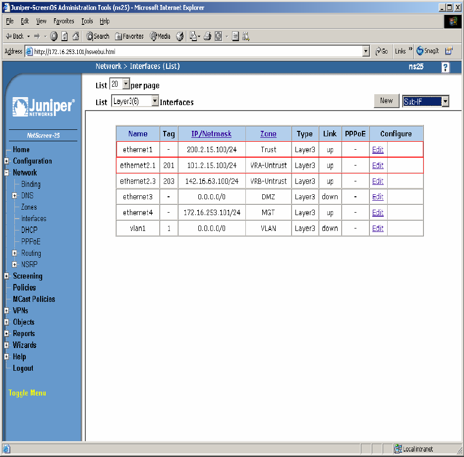
Step 11. Select Network Æ Interfaces in the left pane again to view the list of configured
Interfaces shown in Figure 21. Additional Interfaces are shown that are not related to this
Application Note.
Figure 21
TC; Reviewed:
PV 04/24/2006 Avaya – Proprietary
Use as authorized only pursuant to your signed agreement or
Avaya policy. No other disclosure is permitted or authorized.
30 of 61
HT3-LSP-VF.doc
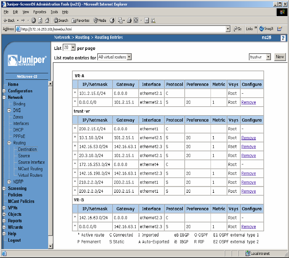
Step 12: In this network environment Static routing is used. The screen capture below is a list of
all routes required for end-to-end LSP connectivity to Avaya Communication Manager. Select
Routing Æ Destination in the left pane to view the list of all routes as shown in Figure 22.
Refer to [1] for more information.
Figure 22
TC; Reviewed:
PV 04/24/2006 Avaya – Proprietary
Use as authorized only pursuant to your signed agreement or
Avaya policy. No other disclosure is permitted or authorized.
31 of 61
HT3-LSP-VF.doc
Step 13. Policies decide what traffic and protocols are permitted from one security zone to
another. Policies for specific protocols and applications were not configured. Any to MIP
policies were configured from one zone to another to verify LSP to Avaya Communication
Manager Registration and File Sync. From the NetScreen-25 Firewall Web Admin screen, select
Policies in the left window pane. Create a Policy for permitting traffic from VRA-Untrust Zone
to Trust Zone as shown in Figure 23. From the Destination Address Book Entry pull down menu
select the MIP entry added in Figure 18 and leave all other options as default values and click
OK.
Figure 23
TC; Reviewed:
PV 04/24/2006 Avaya – Proprietary
Use as authorized only pursuant to your signed agreement or
Avaya policy. No other disclosure is permitted or authorized.
32 of 61
HT3-LSP-VF.doc
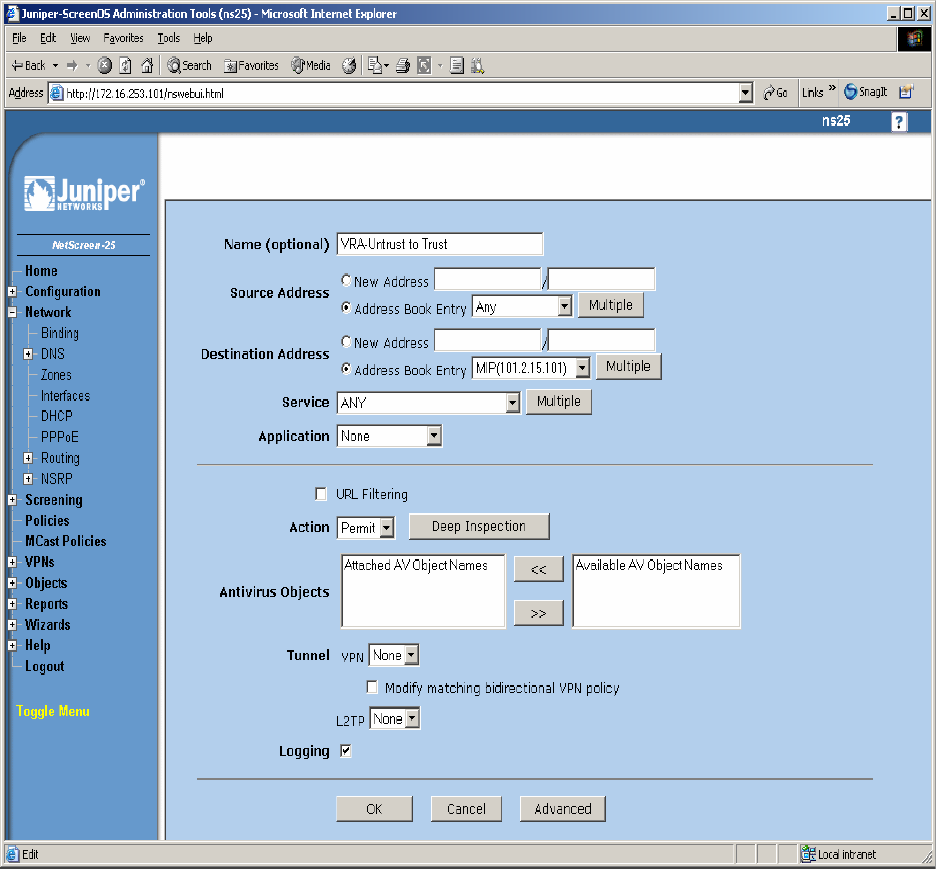
Step 14. From the NetScreen-25 Firewall Web Admin screen, select Policies in the left window
pane. Create a Policy for permitting traffic from Trust Zone to VRA-Untrust Zone as shown in
Figure 24. From the Destination Address Book Entry pull down menu select the MIP entry
added in Figure 20 and leave all other options as default values and click OK.
Figure 24
TC; Reviewed:
PV 04/24/2006 Avaya – Proprietary
Use as authorized only pursuant to your signed agreement or
Avaya policy. No other disclosure is permitted or authorized.
33 of 61
HT3-LSP-VF.doc
Step 15. Select Policies in the left pane to view the list of configured policies as shown in
Figure 25.
Figure 25
TC; Reviewed:
PV 04/24/2006 Avaya – Proprietary
Use as authorized only pursuant to your signed agreement or
Avaya policy. No other disclosure is permitted or authorized.
34 of 61
HT3-LSP-VF.doc
6.1.4. Configure the Juniper VF 3000 SBC
The following section describes how to configure the Juniper VF 3000 SBC for LSP enterprise
sites. Only the Signaling Card (SC) needs to be updated, not the Media Card (MC). In a High
Reliability (HA) configuration, both the master and backup (SC) needs to be updated. This
document assumes that Juniper VF 3000 SBC basic provisioning has been performed. Refer to
[2] for more information. The steps below are for enterprise site A1.
Connect to the (SC) interface of the Juniper VF 3000 SBC via the console port or telnet to the
management interface, which should already be administered.
Step 1. Enter “privileged” mode to input configuration and management commands. Enter the
“privilege” mode password. Enter command blade session-routing Æ then sr-policy (policy to
be modified) then option Æ and then lsp-address <IP address> to add the Native LSP IP
address to the sr-policy defined for enterprise site A1 as shown in Figure 26.
Figure 26
TC; Reviewed:
PV 04/24/2006 Avaya – Proprietary
Use as authorized only pursuant to your signed agreement or
Avaya policy. No other disclosure is permitted or authorized.
35 of 61
HT3-LSP-VF.doc
Step 2. Enter command exit Æ and then show to verify sr-policy configuration as shown in
Figure 27.
Figure 27
TC; Reviewed:
PV 04/24/2006 Avaya – Proprietary
Use as authorized only pursuant to your signed agreement or
Avaya policy. No other disclosure is permitted or authorized.
36 of 61
HT3-LSP-VF.doc

6.2. G650/C-LAN Configuration (Private-Public-Private)
6.2.1. Configure Avaya Communication Manager
The following Avaya Communication Manager provisioning is required to support the LSP
Configuration. This provisioning is performed via the SAT interface. In the following example,
the Avaya Communication Manager for LSP support is provisioned for site B1. Refer to [3] for
additional configuration information for Avaya Communication manager.
6.2.1.1. License Avaya Communication Manager
Avaya Communication Manager must be licensed to enable the special application “SA8853
Support of LSPs behind NAT”.
Step 1. Use the “change system-parameters special-applications” command to enable the
special application “SA8853 Support of LSPs behind NAT”. Select Esc-n to page for SA8853,
select y and submit the changes as shown in Figure 28.
Figure 28
Note: If this feature is installed as a patch (red feature) the feature will not show up on the Avaya
Communication Manager SA form as shown above. In a subsequent GA release, the feature
(green feature) will be part of the SA form, which can be enabled based on licensing.
TC; Reviewed:
PV 04/24/2006 Avaya – Proprietary
Use as authorized only pursuant to your signed agreement or
Avaya policy. No other disclosure is permitted or authorized.
37 of 61
HT3-LSP-VF.doc
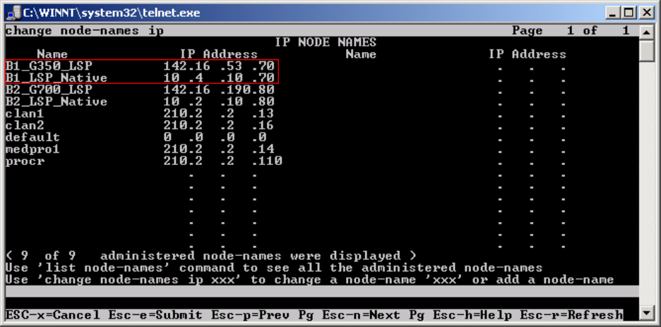
6.2.1.2. Configure Avaya Communication Manager for LSP Support
Step 1. Use the “change node-names ip” command to add the name and IP Address of the LSP
Native IP Address and static 1-to-1 NAT LSP IP address configured in the Checkpoint Firewall
(Figure 49) to the node-names form shown in Figure 29. Submit the changes.
Figure 29
TC; Reviewed:
PV 04/24/2006 Avaya – Proprietary
Use as authorized only pursuant to your signed agreement or
Avaya policy. No other disclosure is permitted or authorized.
38 of 61
HT3-LSP-VF.doc
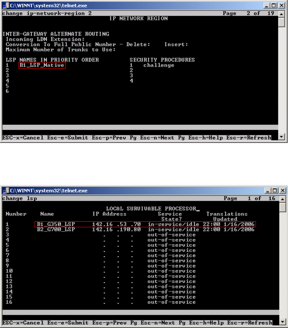
Step 2. Use the “change ip-network-region <region number>” command to add the LSP Native
IP Address to the appropriate Network Region shown in Figure 30. Submit the changes.
Figure 30
Step 3. Use the “change lsp” command to add the static 1-to-1 LSP IP address configured in the
Checkpoint Firewall (Figure 49) to the LSP form shown in Figure 31. Submit the changes.
Figure 31
TC; Reviewed:
PV 04/24/2006 Avaya – Proprietary
Use as authorized only pursuant to your signed agreement or
Avaya policy. No other disclosure is permitted or authorized.
39 of 61
HT3-LSP-VF.doc
TC; Reviewed:
PV 04/24/2006 Avaya – Proprietary
Use as authorized only pursuant to your signed agreement or
Avaya policy. No other disclosure is permitted or authorized.
40 of 61
HT3-LSP-VF.doc
6.2.2. Configure Avaya Local Survivable Processors (LSP)
Local Survivable Processors (LSP) are normally configured to register directly to Avaya
Communication Manager. In the Avaya Hosted IP Telephony environment, the LSPs must be
provisioned to register to Avaya Communication Manager via the static 1-to-1 NAT IP address
of the NetScreen-25 Firewall (Figures 37 and 38) serving the NAT enterprise site. This
provisioning is performed via the LSP web GUI interface. In the following example, the LSP for
site B1 is provisioned. Each LSP must be licensed to enable the special application “SA8853
Support of LSPs behind NAT”. Refer to section 6.2.1.1 for instructions on the configuration.
1. Connect to the services port of the LSP and log into the web GUI.
2. From the GUI select “Launch Maintenance Web Interface”.
3. From the Maintenance page select “Configure Server” from the menu in the left hand
column.
4. Select “Continue”, and then “Continue” again.
5. Select “Configure Individual Services” and select “Continue”.
6. Select “Configure LSP” and the window shown in Figure 32 will open.
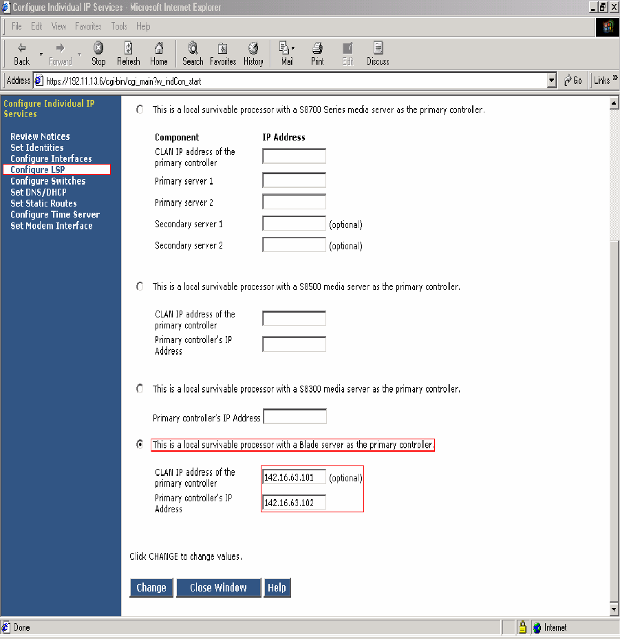
Figure 32 - LSP Configuration Web Page
7. Select “This is a local survivable processor with a Blade server as the primary
controller”. This option was selected for the Avaya SBS3000 shared blade server.
8. In the “CLAN IP address of the primary controller” and “Primary controller’s IP
address” fields, enter the IP address of the data center NetScreen-25 Firewall Untrusted
side Static 1-to-1 NAT Address. In this example, the LSP is associated with IP address
142.16.63.101, which is the NAT IP address for C-LAN in the Data Center and IP address
142.16.63.102, which is the NAT IP address for the Avaya Communication Manager in the
Data Center and associated with Customer B1 NAT site.
TC; Reviewed:
PV 04/24/2006 Avaya – Proprietary
Use as authorized only pursuant to your signed agreement or
Avaya policy. No other disclosure is permitted or authorized.
41 of 61
HT3-LSP-VF.doc
6.2.3. Configuring the Juniper NetScreen-25 Firewall
This Section assumes that Juniper NetScreen-25 Firewall basic provisioning has been performed.
Refer to [1] for more information. Refer to section 6.1.3 for Netscreen-25 Firewall login
procedures and for common configuration parameters for Virtual Router (trust-vr).
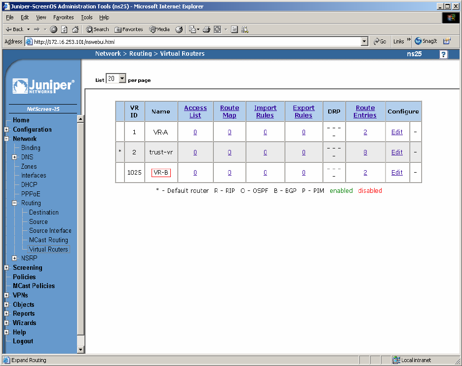
Step 1. Create a Virtual Router for enterprise site B (VR-B). From the left pane click on
Network Æ Routing Æ Virtual Routers. On the right pane, click the New button on the top
right hand corner to create a new Virtual Router. Set Virtual Router Name and leave all other
options as default values and click OK. Figure 33 shows the result of the configured Virtual
Router (VR-B). Refer to [1] for additional configuration information.
Figure 33
TC; Reviewed:
PV 04/24/2006 Avaya – Proprietary
Use as authorized only pursuant to your signed agreement or
Avaya policy. No other disclosure is permitted or authorized.
42 of 61
HT3-LSP-VF.doc

Step 2. Create security zones and assign the zone to the appropriate Virtual Routers. From the
left hand panel of the NetScreen-25 Firewall Web admin screen, click on Network Æ Zones.
From the right hand pane, click the New button to create a new zone. Create security zones for
the Virtual Router untrusted side (VR-B), zone name “VRB-Untrust” shown in Figure 34 and
leave all other options as default values and click OK.
Figure 34
TC; Reviewed:
PV 04/24/2006 Avaya – Proprietary
Use as authorized only pursuant to your signed agreement or
Avaya policy. No other disclosure is permitted or authorized.
43 of 61
HT3-LSP-VF.doc
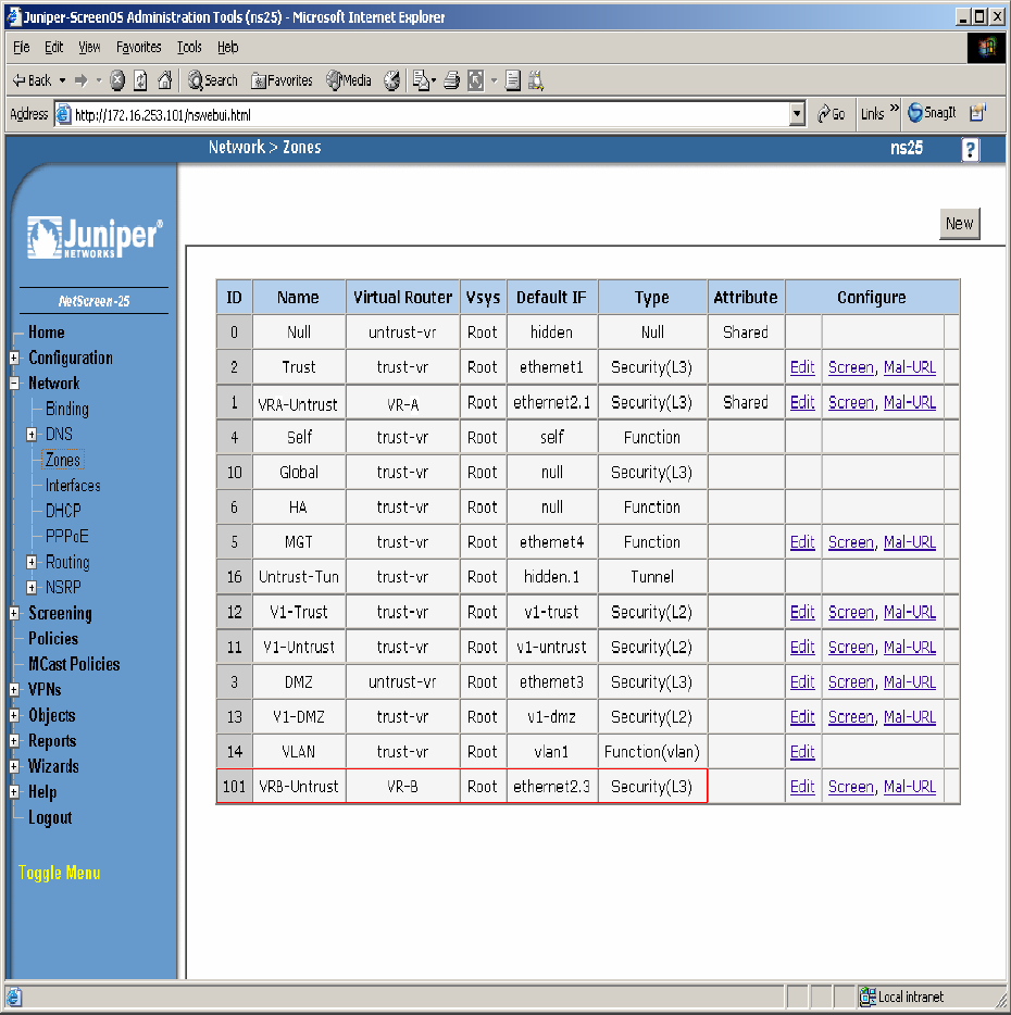
Step 3. Select Network Æ Zones in the left pane to view the list of configured zones as shown
in Figure 35 and click OK. Additional Zones are shown that are not related to this Application
Note.
Figure 35
TC; Reviewed:
PV 04/24/2006 Avaya – Proprietary
Use as authorized only pursuant to your signed agreement or
Avaya policy. No other disclosure is permitted or authorized.
44 of 61
HT3-LSP-VF.doc
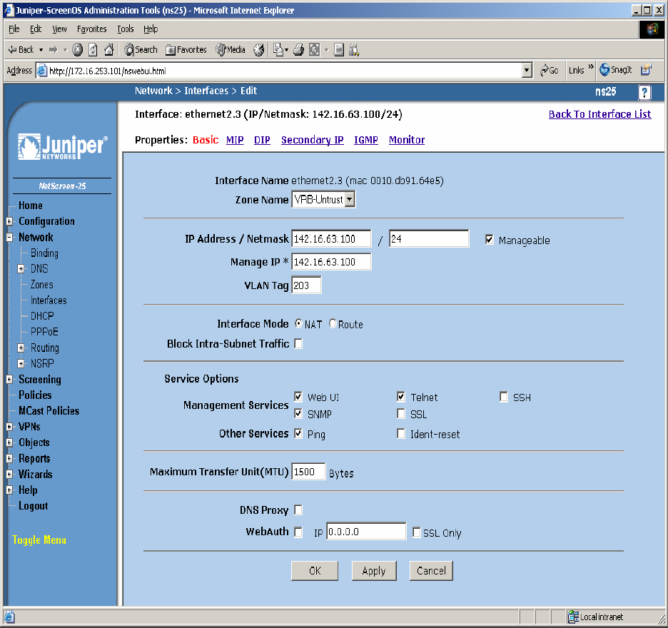
Step 4. Configure Interface with Mapped IP (MIP). The physical interface toward enterprise site
B is configured using sub-interfaces. The physical interface toward the Data Center does not use
sub-interfaces. From the NetScreen-25 Firewall Web Admin screen, click on Network Æ
Interfaces, and select Sub-IF on drop down menu then click the New button from the right hand
window pane. Create Sub-Interface ethernet2.3, zone VRB-Untrust. Configure Interface for
Zone Name, IP Address, VLAN Tag, Interface Mode and Service Options as shown in Figure 36
and leave all other options as default values and click OK.
Figure 36
TC; Reviewed:
PV 04/24/2006 Avaya – Proprietary
Use as authorized only pursuant to your signed agreement or
Avaya policy. No other disclosure is permitted or authorized.
45 of 61
HT3-LSP-VF.doc
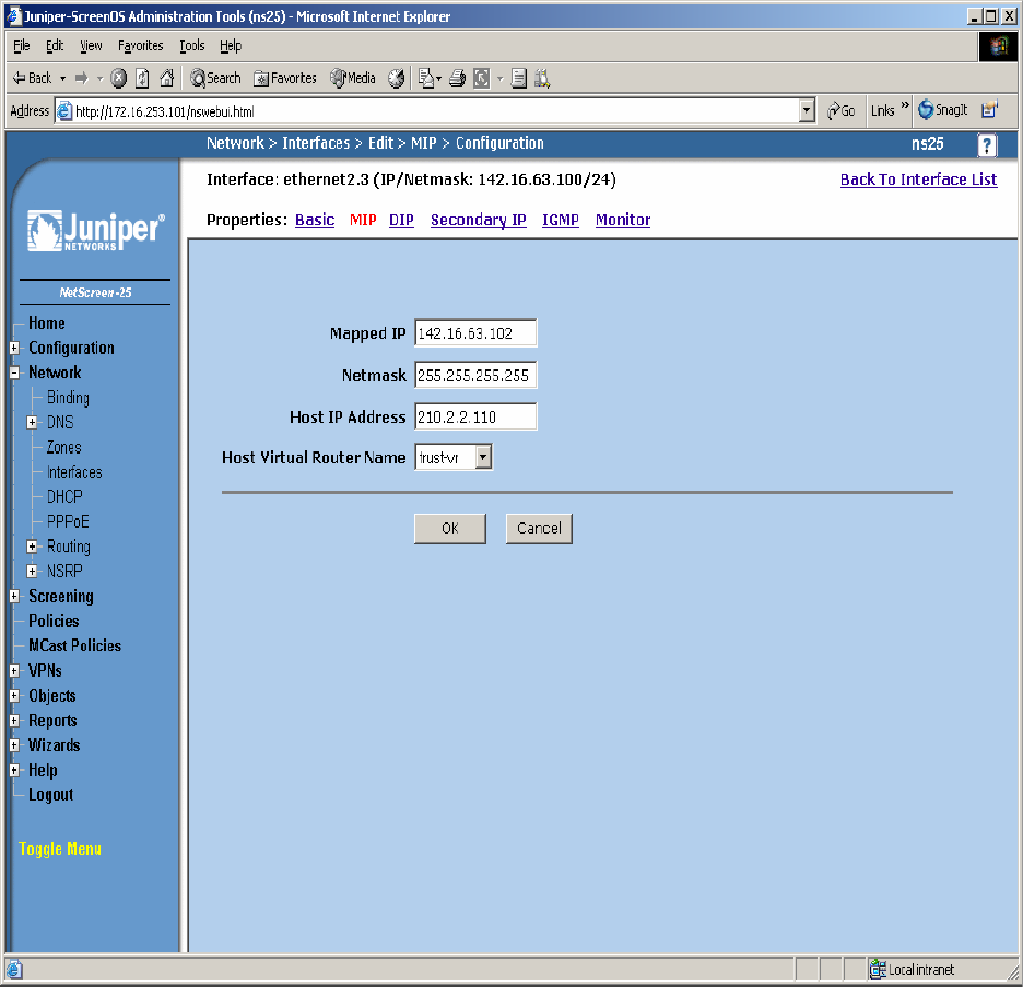
Step 5. Configure Sub-Interface ethernet2.3 MIP for LSP to Avaya Communication Manager
Static 1-to-1 NAT. From the NetScreen-25 Firewall Sub-IF screen, select MIP, and click the
New button from the right hand window pane. Configure MIP as shown in Figure 37 and click
OK.
Figure 37
TC; Reviewed:
PV 04/24/2006 Avaya – Proprietary
Use as authorized only pursuant to your signed agreement or
Avaya policy. No other disclosure is permitted or authorized.
46 of 61
HT3-LSP-VF.doc
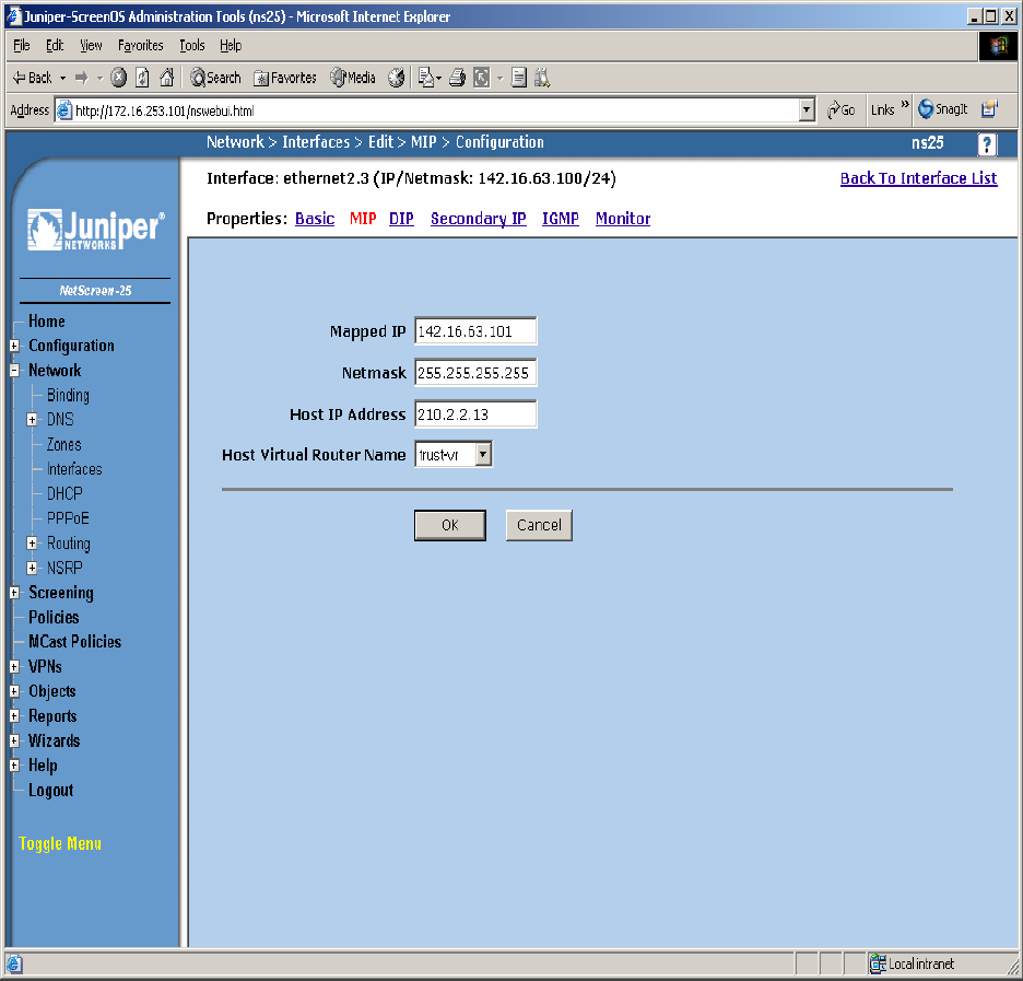
Step 6. Configure Sub-Interface ethernet2.3 MIP for LSP to C-LAN Static 1-to-1 NAT. From
the NetScreen-25 Firewall Sub-IF screen, select MIP, and click the New button from the right
hand window pane. Configure MIP as shown in Figure 38 and click OK.
Figure 38
TC; Reviewed:
PV 04/24/2006 Avaya – Proprietary
Use as authorized only pursuant to your signed agreement or
Avaya policy. No other disclosure is permitted or authorized.
47 of 61
HT3-LSP-VF.doc
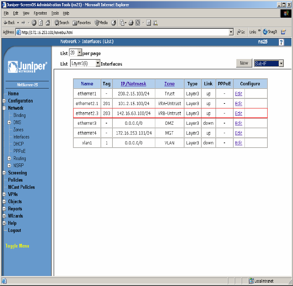
Step 7. Select Network Æ Interfaces in the left pane again to view the list of configured
Interfaces shown in Figure 39. Additional Interfaces are shown that are not related to this
Application Note.
Figure 39
TC; Reviewed:
PV 04/24/2006 Avaya – Proprietary
Use as authorized only pursuant to your signed agreement or
Avaya policy. No other disclosure is permitted or authorized.
48 of 61
HT3-LSP-VF.doc

Step 8. In this network environment Static routing is used. In the screen capture below is a list of
all routes required for end-to-end LSP connectivity to Avaya Communication Manager. Select
Routing Æ Destination in the left pane to view the list of all routes shown in Figure 40. Refer
to [1] for more information.
Figure 40
TC; Reviewed:
PV 04/24/2006 Avaya – Proprietary
Use as authorized only pursuant to your signed agreement or
Avaya policy. No other disclosure is permitted or authorized.
49 of 61
HT3-LSP-VF.doc

Step 9. Policies decide what traffic and protocols are permitted from one security zone to
another. Policies for specific protocols and applications were not configured. Any to MIP
policies were configured from one zone to another to verify LSP to Avaya Communication
Manager Registration and File Sync. From the NetScreen-25 Firewall Web Admin screen, select
Policies in the left window pane. Create a Policy for permitting traffic from VRB-Untrust Zone
to Trust Zone as shown in Figure 41. From the Destination Address Book Entry pull down menu
select the MIP entry added in Figure 37 and leave all other options as default values and click
OK.
Figure 41
TC; Reviewed:
PV 04/24/2006 Avaya – Proprietary
Use as authorized only pursuant to your signed agreement or
Avaya policy. No other disclosure is permitted or authorized.
50 of 61
HT3-LSP-VF.doc

Step 10. From the NetScreen-25 Firewall Web Admin screen, select Policies in the left window
pane. Create a Policy for permitting traffic from VRB-Untrust Zone to Trust Zone shown in
Figure 42. From the Destination Address Book Entry pull down menu select the MIP entry
added in Figure 38 and leave all other options as default values and click OK.
Figure 42
TC; Reviewed:
PV 04/24/2006 Avaya – Proprietary
Use as authorized only pursuant to your signed agreement or
Avaya policy. No other disclosure is permitted or authorized.
51 of 61
HT3-LSP-VF.doc

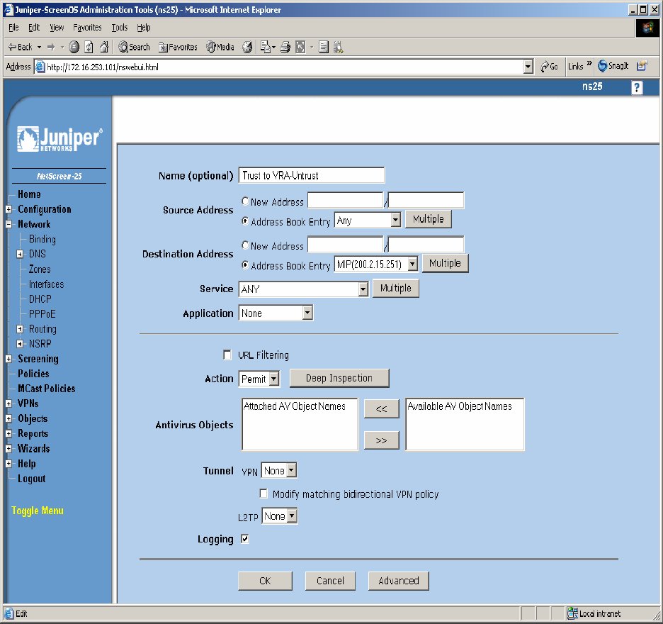
Step 11. From the NetScreen-25 Firewall Web Admin screen, select Policies in the left window
pane. Create a Policy for permitting traffic from Trust Zone to VRB-Untrust Zone as shown in
Figure 43 and leave all options as default values and click OK.
Figure 43
TC; Reviewed:
PV 04/24/2006 Avaya – Proprietary
Use as authorized only pursuant to your signed agreement or
Avaya policy. No other disclosure is permitted or authorized.
52 of 61
HT3-LSP-VF.doc
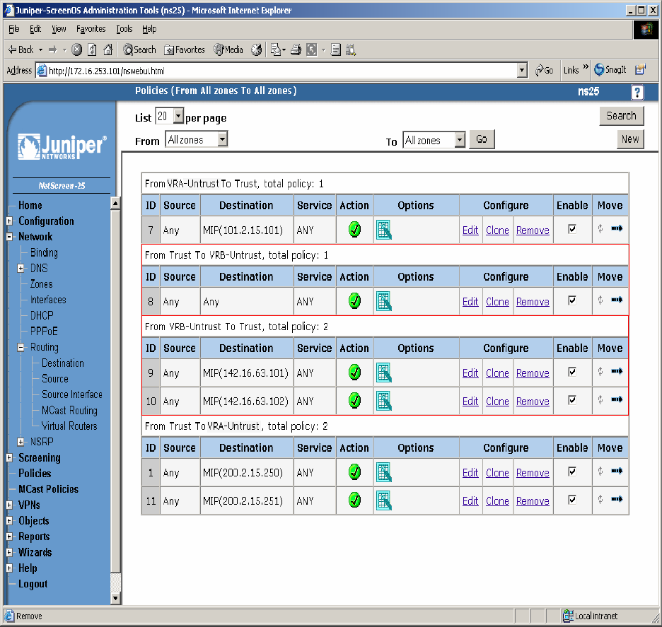
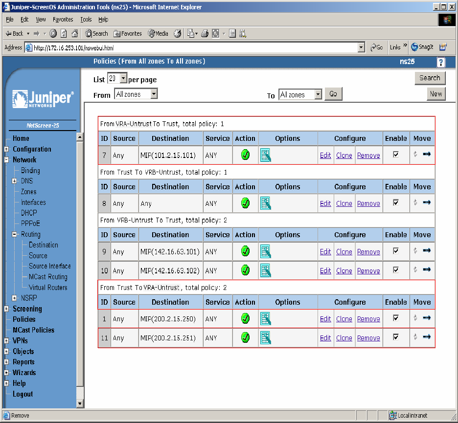
Step 12. Select Policies in the left pane to view the list of configured policies as shown in
Figure 44.
Figure 44
TC; Reviewed:
PV 04/24/2006 Avaya – Proprietary
Use as authorized only pursuant to your signed agreement or
Avaya policy. No other disclosure is permitted or authorized.
53 of 61
HT3-LSP-VF.doc
6.2.4. Configure the Juniper VF 3000 SBC
The following section describes how to configure the Juniper VF 3000 SBC for LSP enterprise
sites. Only the Signaling Card (SC) needs to be updated, not the Media Card (MC). In a High
Reliability (HA) configuration, both the master and backup (SC) needs to be updated. This
document assumes that Juniper VF 3000 SBC basic provisioning has been performed. Refer to
[2] for more information. The steps below are for enterprise site B1.
Connect to the (SC) interface of the Juniper VF 3000 SBC via the console port or telnet to the
management interface, which should already be administered.
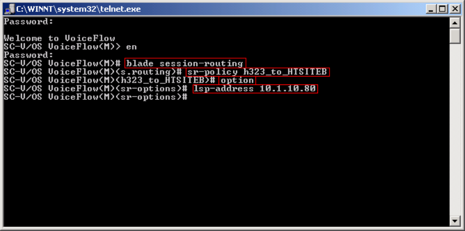
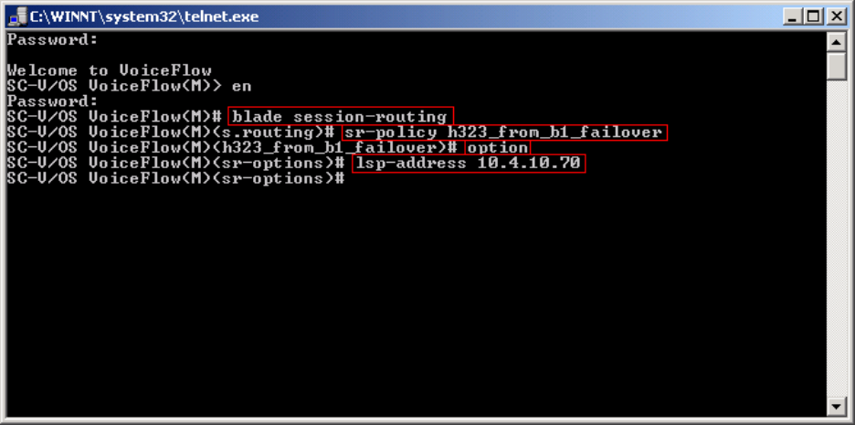
Step 1. Enter “privileged” mode to input configuration and management commands. Enter the
“privilege” mode password. Enter command blade session-routing Æ then sr-policy (policy to
be modified) then option Æ and then lsp-address <IP address> to add the Native LSP IP
address to the sr-policy defined for enterprise site B1 as shown in Figure 45.
Figure 45
TC; Reviewed:
PV 04/24/2006 Avaya – Proprietary
Use as authorized only pursuant to your signed agreement or
Avaya policy. No other disclosure is permitted or authorized.
54 of 61
HT3-LSP-VF.doc
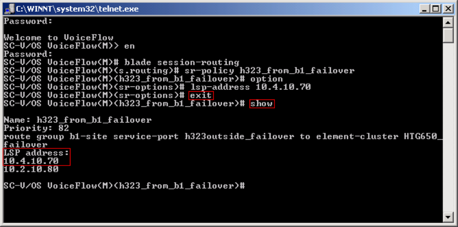
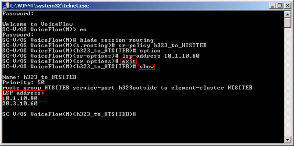
Step 2. Enter command exit Æ and then show to verify sr-policy configuration as shown in
Figure 46.
Figure 46
TC; Reviewed:
PV 04/24/2006 Avaya – Proprietary
Use as authorized only pursuant to your signed agreement or
Avaya policy. No other disclosure is permitted or authorized.
55 of 61
HT3-LSP-VF.doc
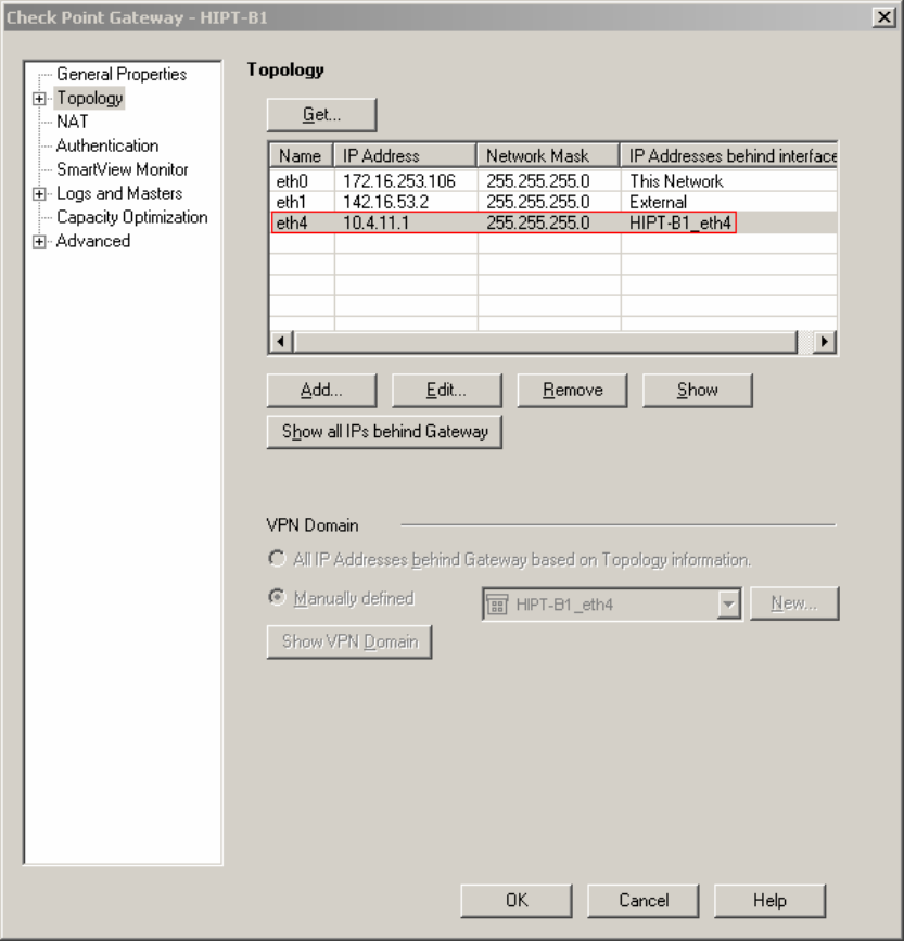
6.2.5. Enterprise Customer Checkpoint Firewall Configuration
The firewall at the enterprise sites must be configured to provide static 1-to-1 NAT for LSP to
Avaya Communication Manager connectivity. The following example in Figure 47 is shown for
Checkpoint Firewall HIPT-B1 located in enterprise site B1. The Group HIPT-B1_eth4 is made
up of several defined networks: one for the outside Checkpoint address (142.16.53.0), one for the
B1 Private Data LAN (10.4.11.0).
Step 1. From Checkpoint Smart Dashboard application, Select Network Objects Æ Checkpoint
Æ HIPT-B1Æ Topology as shown in Figure 47.
A static 1-to-1 NAT will be added to the HIPT-B1_eth4 topology in steps 2-4.
Figure 47: Checkpoint Topology Configuration
TC; Reviewed:
PV 04/24/2006 Avaya – Proprietary
Use as authorized only pursuant to your signed agreement or
Avaya policy. No other disclosure is permitted or authorized.
56 of 61
HT3-LSP-VF.doc
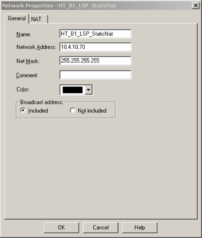
Step 2. From Checkpoint Smart Dashboard application, Select Network Objects, right click
mouse on Networks and select New Networks. At the General tab, add the private Network IP
Address as shown in Figure 48 and click OK.
Figure 48: General Properties of B1 LSP Static NAT
TC; Reviewed:
PV 04/24/2006 Avaya – Proprietary
Use as authorized only pursuant to your signed agreement or
Avaya policy. No other disclosure is permitted or authorized.
57 of 61
HT3-LSP-VF.doc
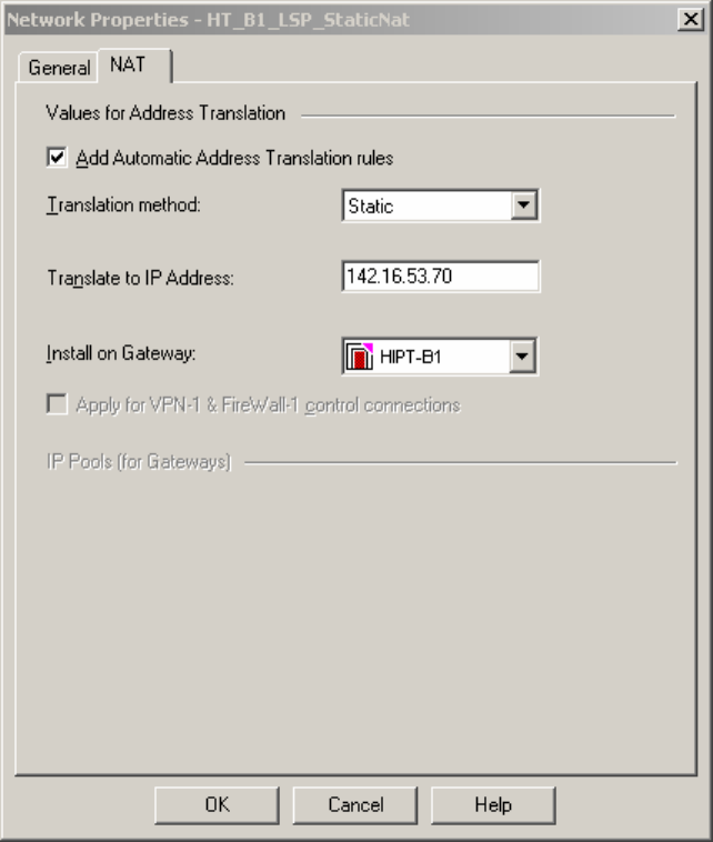
Step 3. Select the NAT tab, then add a static 1-to-1 NAT. The Translate to IP address is the
public WAN IP address and then select HIPT-B1 from the Install on Gateway pull down menu as
shown in Figure 49 and click OK.
Figure 49: NAT Properties of B1 LSP Static NAT
TC; Reviewed:
PV 04/24/2006 Avaya – Proprietary
Use as authorized only pursuant to your signed agreement or
Avaya policy. No other disclosure is permitted or authorized.
58 of 61
HT3-LSP-VF.doc
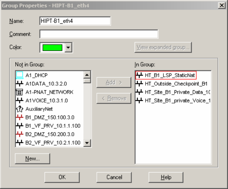
Step 4. From Checkpoint Smart Dashboard application, Select Network Objects Æ Group Æ
HIPT-B1_eth4. Add the static 1-to-1 NAT called “HT_B1_LSP_StaticNat” from the Not in
Group table to the In Group table and click OK as shown in Figure 50. To activate changes
made to HIPT-B1, select Policy Æ Install from the Checkpoint SmartDashboard menu. Select
HIPT-B1 Æ OK for policy changes to be activated.
Figure 50: Group Properties
7. Verification
The following are steps that can be used to verify the configuration described in these
Application notes are correct.
• Verify the Media Gateway in the enterprise site is registered with Avaya Communication
Manager by running the “list media gateway” command from the SAT interface. The
Media Gateway form will show a “y” to the right of the screen for each Media Gateway
that is registered.
• Verify LSP IP connectivity from the enterprise site to Avaya Communication Manager.
To verify, run command “ping” from Avaya Communication Manager and Local
Survivable Processor (LSP) enterprise site. The results should have no packet loss.
• Verify the LSP in the enterprise site is registered with Avaya Communication Manager
by running the “disp lsp”command from the SAT interface. The lsp form will show
Service State (In Service) for each LSP registered to Avaya Communication Manager.
TC; Reviewed:
PV 04/24/2006 Avaya – Proprietary
Use as authorized only pursuant to your signed agreement or
Avaya policy. No other disclosure is permitted or authorized.
59 of 61
HT3-LSP-VF.doc

TC; Reviewed:
PV 04/24/2006 Avaya – Proprietary
Use as authorized only pursuant to your signed agreement or
Avaya policy. No other disclosure is permitted or authorized.
60 of 61
HT3-LSP-VF.doc
• Verify the Avaya Communication Manager is updating the LSP by running command
“save trans lsp” from the SAT interface. Use command “disp lsp” to verify the
translation updated the time and date.
8. Conclusion
These Application Notes describe the procedures for provision the Local Survivable Processor
(LSP) in an Avaya Hosted IP Telephony R3.0 environment. The steps provided should be helpful
for implementing most deployments, but do not address all possible configuration scenarios.
9. References
[1] Configuring the Juniper NetScreen-25 Firewall, User Manual, Release 5.1.0.
Available from Juniper Networks at http://www.juniper.net/
[2] VF Series, JUNIPER VF 3000 SBC, Installation and User Manual, Release 6.0.3.
Available from Juniper Networks at http://www.juniper.net/
[3] Administration Guide for Avaya Communication Manager, Doc ID 03-30050.
10. Glossary
Technical Term Definition as it pertains to this document
HIPT Hosted IP Telephony
HCC Hosted Contact Center
LSP Local Survivable Processor
CM Communication Manager
PE Processor Ethernet
SBC Session Boarder Controller
MIP Mapped IP
SRP Session Routing Policy
FW Firewall
NAT Network Address Translation

TC; Reviewed:
PV 04/24/2006 Avaya – Proprietary
Use as authorized only pursuant to your signed agreement or
Avaya policy. No other disclosure is permitted or authorized.
61 of 61
HT3-LSP-VF.doc
©2006 Avaya Inc. All Rights Reserved.
Avaya and the Avaya Logo are trademarks of Avaya Inc. All trademarks identified by ® and ™
are registered trademarks or trademarks, respectively, of Avaya Inc. All other trademarks are the
property of their respective owners. The information provided in these Application Notes is
subject to change without notice. The configurations, technical data, and recommendations
provided in these Application Notes are believed to be accurate and dependable, but are
presented without express or implied warranty. Users are responsible for their application of any
products specified in these Application Notes.
Please e-mail any questions or comments pertaining to these Application Notes along with the
full title name and filename, located in the lower right corner, directly to the Avaya Solution &
Interoperability Test Lab at interoplabnotes@list.avaya.com
