Avery Dennison Retail Information Services WJSX2000 RFID Printer Transmitter Module User Manual CERTIFICATE OF COMPLIANCE
Avery Dennison Retail Information Services, LLC RFID Printer Transmitter Module CERTIFICATE OF COMPLIANCE
Manual

Rhein Tech Laboratories Client: Paxar Americas, Inc.
360 Herndon Parkway FCC: Part 15.247
Suite 1400 IC: RSS-210
FCC ID: GU6WJSX2000 Herndon, VA 20170
http://www.rheintech.com Model : AlienC1915 RFID Module
Page 45 of 64
APPENDIX I: MANUAL
Please refer to the following pages.
Monarch
9855 RFID
Printer
TC9855RFIDQR Rev. AA 3/04 ©2004 Paxar Americas, Inc. All rights reserved.
BETA

Each product and program carries a respective written warranty, the only warranty
on which the customer can rely. Paxar reserves the right to make changes in the
product, the programs, and their availability at any time and without notice.
Although Paxar has made every effort to provide complete and accurate information
in this manual, Paxar shall not be liable for any omissions or inaccuracies. Any
update will be incorporated in a later edition of this manual.
2004 Paxar Americas, Inc. All rights reserved. No part of this publication may be
reproduced, transmitted, stored in a retrieval system, or translated into any
language in any form by any means, without the prior written permission of Paxar
Americas, Inc.
WARNING
This equipment has been tested and found to comply with the limits for a Class A digital device,
pursuant to Part 15 of the FCC Rules. These limits are designed to provide reasonable protection
against harmful interference when the equipment is operated in a commercial environment. This
equipment generates, uses, and can radiate radio frequency energy and, if not installed and used in
accordance with the instruction manual, may cause harmful interference to radio communications.
Operation of this equipment in a residential area is likely to cause harmful interference in which case
the user will be required to correct the interference at his own expense.
CANADIAN D.O.C. WARNING
This digital apparatus does not exceed the Class A limits for radio noise emissions from digital
apparatus set out in the Radio Interference Regulations of the Canadian Department of
Communications.
Le présent appareil numérique n'émet pas de bruits radioélectriques dépassant les limites
applicables aux appareils numériques de la classe A prescrites dans le Réglement sur le brouillage
radioélectrique édicte par le ministère des Communications du Canada.
Regulatory Compliance
Paxar RF products are designed to be compliant with the rules and regulations in
the locations into which they are sold and will be labeled as required. The majority
of Paxar RF devices are type approved and do not require the user to obtain
license or authorization before using the equipment. Any changes or modifications
to Paxar equipment not expressly approved by Paxar could void the user authority
to operate the equipment.
FCC RF Exposure Guidelines
To comply with FCC exposure requirements, antennas that are mounted externally
at remote locations or operating near users at stand-alone desktop of similar
configurations must operate with a minimum separation distance of 20 cm from all
persons.
Declaration of Conformity for RF Exposure:
The radio module has been evaluated under FCC Bulletin OET 65C and found
compliant to the requirements as set forth in CFR 47 Sections 2.1091, 2.1093, and
15.247 (b) (4) addressing RF Exposure from radio frequency devices.
Radio Frequency Interference Requirements
This device complies with Part 15 of the FCC Rules. Operation is subject to the
following two conditions: 1) this device may not cause harmful interference, and 2)
this device must accept any interference that may cause undesired operations.
CAUTION:
The Part 15 radio device operates on a non-interference basis with other devices
operating at this frequency when using the listed antenna.
Collocation Statement:
This device must not be collocated with any other antenna or transmitters.
Radio Frequency Interference Requirements - Canada
This device complies with RSS 210 of Industry Canada. Operation is subject to the
following two conditions: (1) this device may not cause harmful interference and (2)
this device must accept any interference received, including interference that may
cause undesired operation.
This Class A digital apparatus meets the requirements of the Canadian
Interference-Causing Equipment Regulations.
Cet appareil numérique de la Classe A especte toutes les exigencies du Reglement
sur le Materiél Brouilleur du Canada.
Trademarks
Monarch is a registered trademark of Paxar Americas, Inc.
9855 is a trademark of Paxar Americas, Inc.
Paxar is a trademark of Paxar Corporation.
Paxar Americas, Inc.
170 Monarch Lane
Miamisburg, OH 45342
Visit www.paxar.com for sales, service, supplies, information, and telephone
numbers for our locations throughout the world.
TOLL FREE:
1-800-543-6650 (U.S.A.)
1-800-363-7525 (Canada)
1
This
Quick Reference
contains supply loading and general care and maintenance
procedures. For more detailed information, the
Operator’s Handbook
is on the
optional
Tabletops Documentation CD-ROM
or can be downloaded from our Web
site. Check the Web site for the latest release/addendum information.
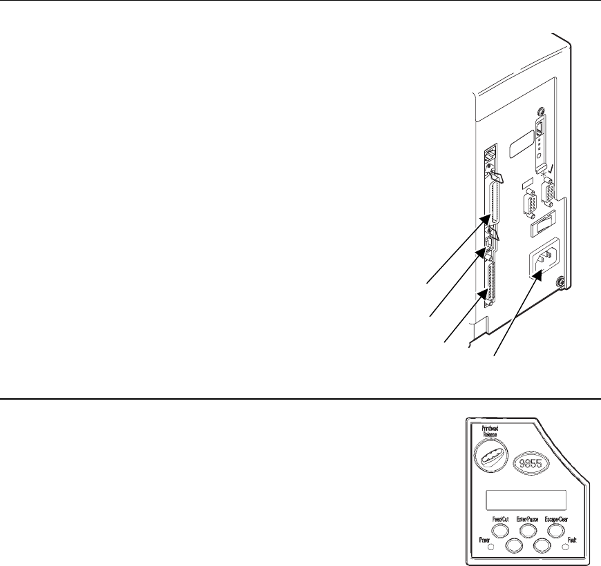
Connecting the Cables
The power supply automatically switches between 115V or 230V. There are no
operator settings required.
1. Plug the power cable into the socket. Plug the other end
of the cable into a grounded electrical outlet.
2. Connect the communication cable into the appropriate port.
Secure the cable with the connecting screws (serial) or
spring clips (parallel).
If you are communicating with the host through the serial
port, make sure the printer's communication values match
those at the host. The factory default values are 9600
Baud, 8 bit data frame, 1 stop bit, no parity, and DTR flow
control. Set the communication values on the printer to
match those at the host.
The printer also has a USB (Universal Serial Bus) Version
1.1 communications port.
Drivers are available on our Web site
for a variety of operating systems.
3. Turn on the printer. Press ( I ) to turn on
and ( O ) to turn off the printer.
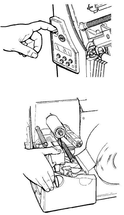
Using the Control Panel
The control panel has a two-line LCD display, 2 status lights,
and five buttons. The control panel displays error
codes/messages, and allows you to setup/configure the
printer.
Power: The printer shows a steady green light when
it is on.
Fault: The printer shows a steady amber light when
it is out of labels or ribbon, or when you have
a supply jam.
Power Cable Goes Here
Serial Port
Parallel Port
USB Port
2
Feed/Cut: Prints a label in the on-demand mode, feeds a blank label if there
is no print job, prints a label with error information that is useful
to your System Administrator if an error is displayed, cuts the
supply when pressed and held for two seconds if a knife is
installed.
Enter/Pause: Pauses the current print job or resumes a paused print job.
Selects the displayed menu item.
Escape/Clear: When an error is present, clears the error. When a job (batch) is
printing, cancels the print job (batch). Enters the offline menu
mode or returns the display to the next higher menu.
ÅDisplays the previous menu item.
Æ Displays the next menu item.
Å and Æ Prints a test label when you press the buttons at the same time.
Hold for one second and release.
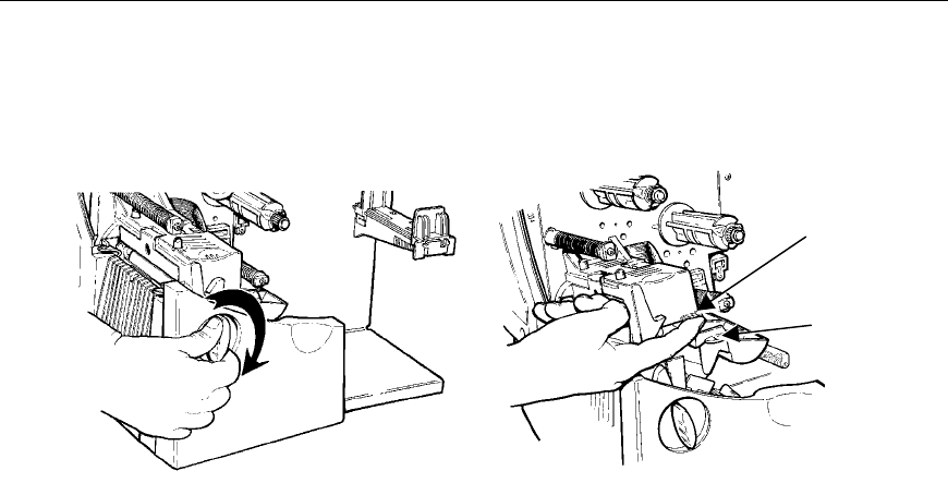
Loading Labels or Tags
1. Open the cover.
2. Unlock the printhead by turning the retaining latch.
3. Lift printhead assembly using the printhead tab until the assembly locks into
place.
4. Place the roll of supply on the supply holder. For labels, the supply unrolls
from the top or the bottom. For tags, make sure the supply unrolls from the
bottom, because tag rolls are wound face in. Do not pick up the printer by
the supply holder.
Printhead
Tab
Deflector
Tab
3
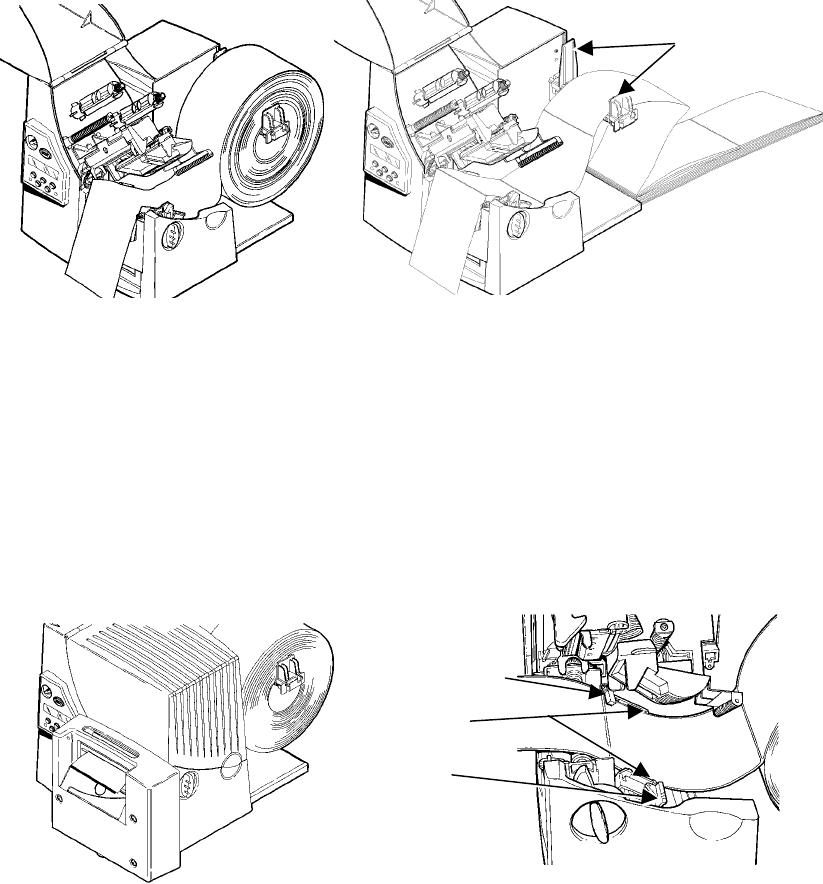
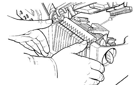
5. Adjust the supply holder guides so the sides barely touch the roll. Make sure
the supply roll turns freely. If you are using fan-fold supplies, place the
supply stack behind the printer, label side facing up.
6. Push down on the supply lever to unlock the supply guides.
7. Lay the label strip across the supply guide so that a few inches extend past the
front of the printer. Tuck the supply under the nibs and in between the die cut
sensor.
For fan-fold supplies, lay the label strip over the supply holder and
across the supply guide so that a few inches extend past the front of the
printer. Tuck the supply under the nibs and in between the die cut sensor.
For tag supplies using the optional knife, feed the supply through the
knife. Make sure at least 0.5 inches of supply is past the knife.
8. Adjust the supply guides so they touch the supply. Push up on the supply lever
to lock the supply guides into place.
Die Cut Sensor
Supply
Lever
Nibs
Supply
Holder
Guides
4
9. Hold the printhead assembly by the printhead tab while pressing down on the
printhead release.
10. Close the printhead by pressing down on the thumb well until you hear it click
into place.
11. Close the cover.
12. Press Feed/Cut to position the supply under the printhead.
5
Loading Labels for the Optional Peel Mode
Peel mode must be purchased separately. In peel mode, the printer separates the
backing paper from the label. The next label is not printed until the completed one
is removed from the printer. Make sure the printer is configured for on-demand
mode and the correct supply type. The minimum feed length is 1.5 inches for peel
mode. Hold the leading edge of peeled labels when printing on stock longer than
six inches. You must use non-perforated supplies for peel mode. Follow the steps
for loading supplies from the previous section. Then, follow these steps after you
close the printhead.
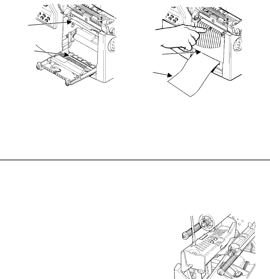
1. Remove the labels from the first 10 inches of the backing paper.
2. Press down on the exit cover tabs to open the exit cover on the front of the
printer.
3. Feed the backing paper over the peel bar.
6
4. Feed the backing paper through the lower opening of the exit cover. Close the
exit cover. Pull down on the backing paper to remove any slack.
When removing the backing paper, pull up across the saw-toothed tear
edge. Make sure the backing paper tears at the edge.
5. Close the printer's cover.
6. Press Feed/Cut to position the supply under the printhead.
To load and use linerless or string tag supplies, refer to the
Operator’s Handbook
.
Adjusting the Wide/Narrow Knobs
You may need to adjust the two wide/narrow knobs according to the width of your
supply. For supply that is more than two inches, adjust the knobs to the wide
setting. For supply that is two inches or less, adjust the knobs to the narrow
setting. For linerless supply, use the narrow setting (knobs are up). For string tag
supplies, use the wide setting (knobs are down).
You must adjust both of the knobs to the same position.
If you experience ribbon smudging in cold, dry
environments, adjust the wide/narrow knobs to the
wide setting.
For wide supplies, push down and turn the
wide/narrow knobs clockwise with a screwdriver.
For narrow supplies, turn the wide/narrow knobs
counter-clockwise with a screwdriver until it pops
back up.
The adjustment is shown in the wide position.
Peel
Bar
Lower
Opening
Tear
Edge
Backing
Paper
7
Loading Ribbon
1. Open the cover.
2. Unlock the printhead by turning the
retaining latch.
3. Lift printhead assembly using the
printhead tab until the assembly locks
into place.
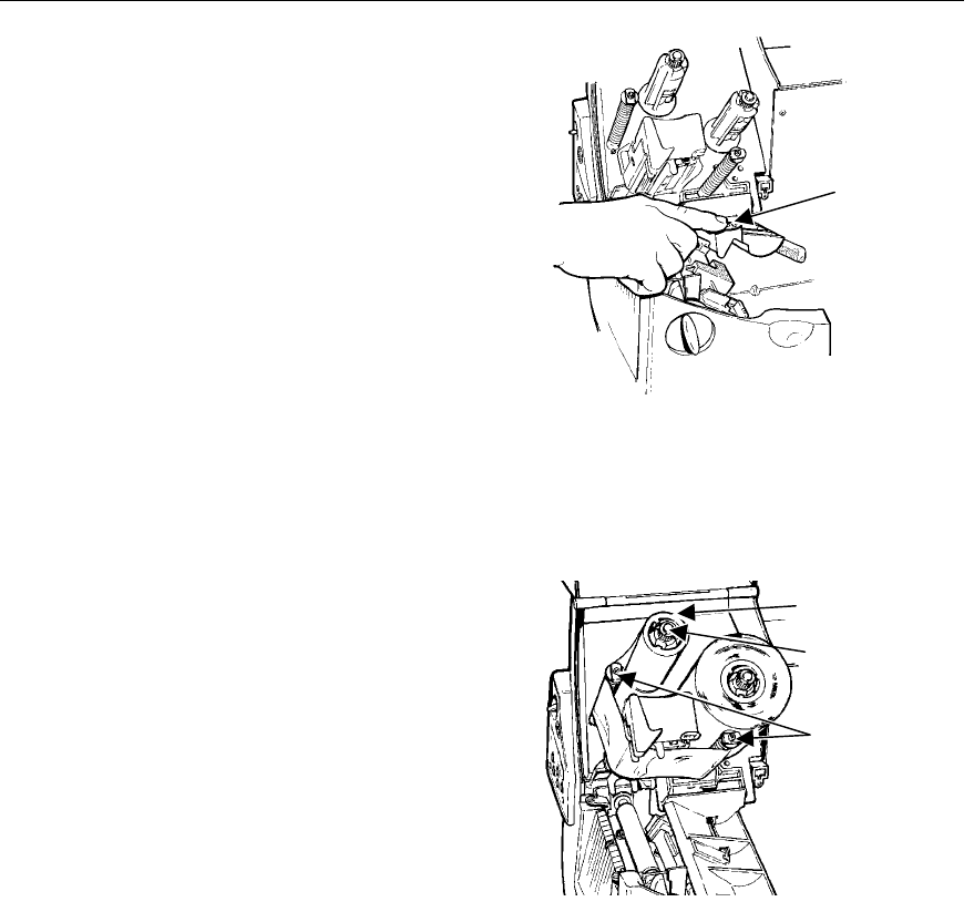
4. Push the deflector tab down.
5. Slide the extra ribbon core on the take-up
reel as far as it will go with the "This End
Out" writing facing out. Use your empty
ribbon core as the take-up core. The
take-up core only fits on the take-up reel
one way.
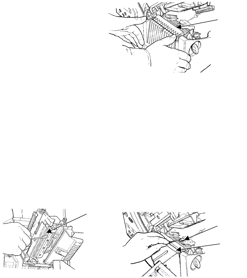
6. Remove the new ribbon from the package. Do not wrinkle or crush the new
ribbon.
7. Slide the ribbon onto the back reel as far as it will go. The ribbon roll only fits
on the reel one way. Carefully unwind a few inches of ribbon from the bottom
of the roll.
8. Carefully feed the ribbon under both
ribbon rollers and printhead.
9. Align the ribbon and make sure it is
straight and centered throughout the
path.
10. Tape the ribbon to the take-up core. Do
not tape the ribbon to the take-up reel.
11. Rotate the take-up core until the leader
is past the printhead.
12. Remove any slack in the ribbon by
turning the take-up reel clockwise.
13. Hold the printhead assembly by the printhead tab while pressing down on the
printhead release.
Deflector
Tab
Take-up Core
Take-up Reel
Ribbon
Rollers

8
14. Close the printhead by pressing down on the thumb well until you hear it click
into place. Close the cover.
Printing
Before you print, make sure the printer is connected and ready to receive data.
1. Turn on the printer. Your printer is ready to receive and print batches when
you see
PRINT MODE
Ready
2. Download a format and a batch. Refer to the optional
Packet Reference
Manual
for information on downloading print jobs.
3. The printer prints a strip of labels.
4. Remove the printed labels. If the printer will be unused for extended periods of
time, we recommend leaving the printhead unlatched.
Universal Serial Bus (USB) Information
This printer has a USB Version 1.1 communications port. Drivers are available for
a variety of operating systems. These drivers provide a Virtual Communications
Port (VCP), which looks like a normal serial port (for example, COM1-4). After
installing the drivers, change the communications port to the one allocated by the
VCP driver. For these drivers, go to our Web site (www.servisource1.com).
Clearing Jams
When you are printing and a jam occurs, the Fault light on the printer's front panel
blinks.
1. Turn off the printer and open the cover and printhead assembly.
2. If necessary, remove the label roll and ribbon.
3. Remove the jammed labels and reload the label roll.
4. Close the printhead assembly and turn on the printer.
5. Press Feed/Cut to position the supply under the printhead.

9
Voids
Streaks
Cleaning
CAUTION: Do not use sharp objects to clean the printhead or touch the printhead.
This may damage the printhead and require a service charge.
NOTE: You must clean the printhead as described below to maintain printhead
life.
The rate and frequency at which you print determines how often you must clean the
printer. You may need to clean the printhead, sensor, and platen roller:
♦ if there is any adhesive build-up in the supply path.
♦ after printing approximately 3 rolls of thermal transfer/thermal
direct/linerless supplies or after each ribbon.
♦ daily if your printer is in an excessively dirty, hot, or humid
environment.
♦ if you frequently receive supply error codes or when you see
voids or streaking in the print as shown.
1. Turn off the printer and open the cover and printhead assembly.
2. Remove the label roll and ribbon (when cleaning the printhead).
3. Press down on the exit cover tabs to open the exit cover on the front of the
printer.
10
4. Clean the platen roller when you see significant adhesive build-up or a label is
wrapped around the platen
roller. Use a dry, soft-bristle
brush, such as a toothbrush, to
clean either the standard
(black) or linerless (red/orange
textured) platen roller.
If the brush does not remove
all the adhesive
♦ use isopropyl alcohol
ONLY on the standard (black) platen roller.
Moisten a cotton swab with isopropyl alcohol and run the cotton
swab across the platen roller. Turn the platen roller with your
finger to make sure the platen roller is clean all the way around.
After cleaning, feed several inches of supply through without
printing to remove any remaining isopropyl alcohol.
♦ call Service to clean the linerless (red/orange textured) platen
roller.
NOTE: DO NOT use alcohol or solvents on linerless (red/orange textured)
platen rollers.
5. Rub the cotton swab moistened with isopropyl alcohol across the peel bar and
remove any build-up.
6. Moisten another cotton swab with isopropyl alcohol. Rub the cotton swab
across the printhead and remove any build-up. You may need to use a
printhead CLEAN-STRIP if the printhead is extremely dirty or you see streaks
on the supply.
7. Rub the cotton swab across the supply sensor and die cut sensor and remove
any build-up.
8. Clean the build-up in the supply path.
Printhead
Supply
Sensor
Peel
Bar
Platen
Roller

11
9. Let the printer dry before you reload supplies.
10. Close the exit cover by pushing firmly on it. Both latches will click into place.
11. Close the cover and printhead assembly.
12. Turn on the printer and press Feed/Cut to position the supply under the
printhead. Resend your format, batch, and check digit packets.
Troubleshooting
This section provides solutions to minor printing problems.
Problem Action
Error message appears during
startup
Turn off the printer, wait fifteen seconds and
then turn on the printer. Call Technical
Support if the error message reappears.
Does not print. Check supply.
Check ribbon.
Send a corrected format and batch packet.
Does not feed. Set wide/narrow knobs correctly.
Partially printed data. Clean the printhead.
Send a corrected format packet.
Printing shadows or smears. Clean the printhead.
Change supply.
Check ribbon.
Light Printing. Change supply.
Adjust the print contrast.
Check wide/narrow knobs.
Check ribbon.
Heavy Printing. Clean the printhead.
Change supply. Adjust the print contrast.
Check wide/narrow knobs.
Check ribbon.

12
Problem Action
Voids in printing. Clean the printhead.
Change supply type.
Check ribbon.
Serial bar codes do not scan. Leave printhead unlatched when not in use.
Use a print speed of 2.5 IPS.
Adjust the print contrast.
Backing paper is wrapped
around platen or peel roller.
Carefully remove the backing paper. Make
sure the backing paper tears at the saw-
toothed tear edge when using backfeed and
peel mode.
Blank labels print or 750 series
errors.
Clean supply sensors.
Common Errors
Error Description/Action
002 Name must be 1 to 8 characters inside quotes.
005 Supply width is invalid.
018 Code page selection defined in the field is invalid.
025 Data length is too long.
101 Format referenced by batch not in memory.
400 Invalid character following {.
403 Field separator was not found.
409 Printer memory is full. Delete unnecessary formats or graphics from
memory.
410 Parity mismatch.
411 Framing error (baud rate mismatch).
412 Flow control mismatch.
413 Online receive buffer is full. Check for a flow control problem.
611 Font, bar code, or density in the batch does not fit the format.
612 The data in this line of the batch is either missing or does not match the
format.
613 Reference point off supply.

13
614 Portion of field off supply or there may be an invalid character in the
packet.
703 The printer sensed a calibration of different-sized black marks. Make
sure the correct supply type is loaded.
704 Printer has not sensed a supply mark when expected or is out of
supplies. Press Escape/Clear and try to continue printing. Change
supply.
751 Printer did not sense a black mark when expected. Press Escape/Clear
and try to continue printing. Change supply.
752 Printer sensed a mark in the wrong place.
753 Printer sensed a mark that is too long.
754 Check for a ribbon jam or remove any slack in the ribbon by turning the
take-up reel clockwise. Load a new ribbon.
755 Printhead is open. Close the printhead.
756 Load supplies.
757 Load supplies (supply length mismatch). Press Feed/Cut.
758 Either the supply is not seen, the on-demand sensor is broken, or a label
was removed too quickly. Check for a label jam or reload supplies.
763 Waiting to dispense label. Press Feed/Cut.
765 The printhead has less than 8 bad dots and can shift bar code fields to
avoid bad dots. Press Escape/Clear to continue printing.
768 Printhead has more than 8 bad dots within the format area or is not
connected. Connect printhead.
Printer Specifications
Height: 12.5 inches (318 mm)
Width: 12 inches (305 mm)
Depth: 13 inches (330 mm)
Weight: 21 lb. (9.5 kg)
Shipping Weight: 25 lb. (11.4 kg)
Power Source: 90-264 VAC with autoselect 50/60Hz
Printhead: Thermal at 4 inches (1012 mm) wide
203 dpi (8.0 dots per mm)
Optional 300 dpi (11.8 dots per mm)

14
Speed: 2.5, 4.0, 6.0, 8.0, and 10.0 ips (inches per second) (2.5 is
default for serial bar codes). 12.0 ips printing is an option
that must be purchased separately.
Maximum Print
Area:
4.0 inches x 16.0 inches (102 mm x 406 mm) with 203 dpi
4.0 inches x 13.0 inches (102 mm x 330 mm) with 300 dpi
Operating Temperature
Direct: 40° F to 104° F (4°C to 40°C)
Transfer: 40°F to 95°F (4°C to 35°C)
Storage: 15°F to 120°F (-9°C to 49°C)
Humidity: 5% to 90% non-condensing
Supply Specifications
Linerless and string tag supplies are also available. For more detailed information,
the
Operator’s Handbook
is on the optional
Tabletops Documentation CD-ROM
or
can be downloaded from our Web site.
Supply Types: Thermal Transfer or Direct
Supply Widths: 0.75 inches (19 mm) minimum
4.25 inches 9108 mm) maximum
Supply Lengths: 0.32 inches (8 mm) minimum
17.5 inches (445) maximum
Supply Thickness: 7 to 12 mils
Ribbon Specifications
Ribbon Widths: Use with Max. Supply Width
1.5 inches (38 mm) 1.3 inches (33 mm)
1.8 inches (46 mm) 1.5 inches (38 mm)
2.3 inches (58 mm) 2.0 inches (51 mm)
3.3 inches (84 mm) 3.0 inches (76 mm)
4.3 inches (110 mm) 4.0 inches (102 mm)
RF Specifications
The radio operates at the 915 Ghz range, frequency hopping.