Aviat Networks 3ECJ68B3E PTP Radio User Manual 862 01881 12c
Aviat Networks PTP Radio 862 01881 12c
Contents
- 1. Manual 1 revised
- 2. Manual 2 revised
Manual 1 revised

MDR2400/5800-SR, Orion2410/5810-SRi and Orion 5825-SR
862-01881 Issue 12c Page 1
MDR2400/5800-SR,
Orion2410/5810-SRi and
Orion5825-SR
Digital Radios
User Manual
Document Number: 862-01881

MDR2400/5800-SR, Orion2410/5810-SRi and Orion 5825-SR
862-01881 Issue 12c Page 2
Issue Status
Issue Revised Pages/Amendments
1 1
2 31
3 2
4 General – terminology definition PER used instead of BER to remove interpretation ambiguity
between Block Error Rate and Bit Error Rate. Note Block (equivalent to packet) concept is still
maintained within sections describing G.826 parameters to maintain consistency with G.826
terminology.
5 MIB Description chapter added, RESET Button Additions, chapter on setup of a serial connection
between a PC/Laptop and the Element Management Port, IP network address description diagrams.
6 Amendments related to customer furnished equipment, RF Unit temperature range update,
Maintenance and Ordering section updates, Appendix added regarding Antennas.
7 Update on RESET Button functionality description, MIB definition additions, product receive sensitivity
level adjustment, FCC notice updates (Warning – this page, Antenna Information – Appendix E), NMS
picture update. Appendix D Digital Indoor Unit firmware Upgrade Notice added. Appendix B MIB
Elements ResetAllRFPerfomanceData and ResetAllG826 deprecated.
8 Added detail for new MDR2400 RF Unit
Added detail for new Digital Indoor Unit – balanced and unbalanced connectors
9 Added detail for Orion 5825 – SR radio (16 QAM radio), 1+1 system. Changed to American English.
Updated MIB as well as NMS, now JAVA based. Support for Windows XP, 2000 added.
Added ftp firmware upload, Appendix G
Added text required by the ATCB with regards to the Orion 5825 – SR.
10 Added additional text required by the ATCB to adhere to FCC requirements.
11 Added description of per trib line code selectivity for T1 interfaces. See Section 2.3.1.
Added Appendix describing the Orion5810i and Orion2410i Indoor RF units.
12 Add text to describe the Orion5810-SRi and Orion2410-Sri and changes requested by Rheintech.
12c Add changes requested by ATCB. (Tx power of +25dBm for Orion5810i)
MDR2400/5800-SR, Orion2410/5810-SRi and Orion 5825-SR
862-01881 Issue 12c Page 3
FEDERAL COMMUNICATIONS COMMISSION NOTICE
The equipment has been tested and found to comply with the limits for a Class A digital devices, pursuant to Part 15 of the
FCC Rules.
These limits are designed to provide reasonable protection against harmful interference when the equipment is operated in
a commercial environment. This equipment generates, uses, and can radiate radio frequency energy and, if not installed
and used in accordance with the instruction manual, may cause harmful interference to radio communications.
Operation of this equipment in a residential area is likely to cause harmful interference in which case the user will be
required to correct the interference at his own expense.
The manufacturer is not responsible for any radio or TV interference caused by unauthorized modifications to this
equipment. Such modifications could void the user's authority to operate the equipment.
This device complies with Part 15 of the FCC Rules. Operation is subject to the following two conditions: (1) this device may
not cause interference, and (2) this device must accept any interference, including interference that may cause undesired
operation of the device.
WARNING- To comply with FCC RF exposure
limits, the antennas for this transmitter must be
fix-mounted to provide a separation distance of 2
meters (6.6 ft) or more from all persons to satisfy
RF exposure requirements.
Equipment installation and use
This equipment must be professionally installed. The operator of the spread spectrum or digitally modulated intentional
radiator, or the installer if the equipment is professionally installed, is responsible for ensuring that the system is used
exclusively for fixed, point-to-point operations.
NOTE 1 The MDR2400 frequency output must be limited to between 2412MHz and 2458MHz and the power to a maximum
of +22dBm (2412-2426MHz) and +18dBm (2458MHz) for the required antennas for compliance to FCC standards, U.S.
only.
NOTE 2 The center frequencies of the ORION5850 radio is limited by firmware between 5731MHz and 5844MHz as
outlined in Sections 2.2.1.4 and 2.2.1.5 and the transmit power is limited to +24dBm. The device must be used with one of
the antennas listed below to comply with FCC standards:
1) Gabriel Electronics parabolic antenna, model number SSP2-52B
2) Harris Corporation flat panel antenna, model number MT-20004.
NOTE 3 The center frequencies of the ORION5810i radio is limited by firmware between 5735MHz and 5840MHz as
outlined in Section 2.2.1.1 and the transmit power is limited to +25dBm. The device must only be used with the antenna
listed below to comply with FCC standards:
1) Gabriel Electronics parabolic antenna, model number SSP2-52B
INDUSTRY CANADA NOTICE
This device has been designed to operate with an antenna having a maximum gain of 33 dBi. Antenna having a higher gain
is strictly prohibited per regulations of Industry Canada. The required antenna impedance is 50 ohms.
Operation is subject to the following two conditions: (1) this device may not cause interference, and (2) this device must
accept any interference, including interference that may cause undesired operation of the device.
Exposure of Humans to RF Fields
The installer of this radio equipment must ensure that the antenna is located or pointed such that it does not emit RF field in
excess of Health Canada limits for the general population; consult Safety Code 6, obtainable from Health Canada's website:
www.hc-sc.gc.ca/rpb

MDR2400/5800-SR, Orion2410/5810-SRi and Orion 5825-SR
862-01881 Issue 12c Page 4
Publication Number: 862-01881
Issue 12
March 2003
© 2003 Tellumat (Pty) Limited
The information contained herein is the property of Tellumat (Pty) Limited and is supplied
without liability for errors or omissions. No part may be reproduced, used or disclosed
except as authorised by contract or other written permission. The copyright and the
foregoing restriction on reproduction, use and disclosure extend to all media in which this
information may be embodied, including magnetic or electronic storage etc.

MDR2400/5800-SR, Orion2410/5810-SRi and Orion 5825-SR
862-01881 Issue 12c Page 5
Table of Contents
Page
1 INTRODUCTION 10
1.1 Radio Description 10
2 TECHNICAL DESCRIPTION 12
2.1 System Overview 12
2.2 RF Unit 12
2.2.1 Frequency plans 13
2.2.2 RF Power Output Options 16
2.2.3 MDR2400, MDR5800, Orion2410i, Orion5810i and Orion 5850 RF Units 17
2.3 MDRMTE, MDRMETU, Orion10 and Orion25 Digital Indoor Unit 17
2.3.1 Payload Interface Options 18
2.3.2 1+1 Redundancy Protected Payload System 19
2.3.3 Digital Indoor Unit Status LEDs 19
2.3.4 Reset / Configuration Button 19
2.3.5 Service (Wayside) Serial Data Channel 21
2.3.6 Element Manager Port 21
2.3.7 10BaseT Ethernet RJ45 Port 22
2.3.8 DIU/RFU Link LED 22
2.3.9 DIU/RFU Data Interconnect RJ45 22
2.3.10 DIU/RFU Power Interconnect 22
2.3.11 Auxiliary In/Out Port 22
2.3.12 DIU DC Power Input 23
2.3.13 Fuse Holder 23
2.3.14 ON/OFF Switch 23
2.3.15 Ground Terminal 23
3 PLANNING 24
3.1 System Type Selection 24
3.1.1 Antenna selection 24
3.2 Site Evaluation 26
3.3 Multipath Effects 26
3.4 Interference Considerations 27
3.5 Microcell Backhaul Applications of MDR / Orion Digital Radios 28
3.5.1 Setting the Transmitted Power Levels 28
3.5.2 Frequency Multiplexing 28
3.5.3 Antenna Isolation 28
4 INSTALLATION 29

MDR2400/5800-SR, Orion2410/5810-SRi and Orion 5825-SR
862-01881 Issue 12c Page 6
4.1 Customer Furnished Tools and Equipment 30
4.2 Digital Indoor Unit 31
4.2.1 Introduction 31
4.2.2 Installing the Digital Indoor Unit in a Rack 31
4.2.3 Connecting a DC Power Supply 32
4.2.4 Balanced Payload Data : DB25 33
4.2.5 Balanced Payload Data : RJ48 34
4.2.6 Unbalanced Payload Data : BNC 34
4.2.7 Connecting Auxiliary In/Out (Optional) 34
4.2.8 Connecting the Service (Wayside) Serial Channel (Optional) 35
4.2.9 Connecting the Element Manager Port 36
4.3 RF Unit 36
4.3.1 RF Connection 36
4.4 Interconnection Cable Installation 37
4.4.1 INTERCONNECTION CABLE WIRING DESCRIPTION 39
5 ANTENNA ALIGNMENT AND SOFTWARE SETUP 40
5.1 Installation Equipment Required 40
5.2 Information Required 40
B.1 Antenna Alignment 40
5.2.1 Introduction 40
5.2.2 Alignment Procedure 40
5.2.3 Set Transmitted Power Level 42
5.3 Software Setup 43
5.4 Functional Test 43
5.4.1 Link Bit Error Rate Performance Test 43
5.5 MDR / Orion Installation Record 44
5.6 MDR / Orion Test Record 45
6 NMS SOFTWARE 46
6.1 Scope 46
6.2 Introduction 46
6.3 System requirements 47
6.4 Installing the NMS 47
6.4.1 JRE Installation 47
6.4.2 NMS Installation 47
6.4.3 NMS Un-Installation 48
6.5 Help documentation 48
7 MAINTENANCE INFORMATION 49
8 TECHNICAL DATA 50
8.1 Environmental Requirements 50

MDR2400/5800-SR, Orion2410/5810-SRi and Orion 5825-SR
862-01881 Issue 12c Page 7
8.1.1 Outdoor Equipment 50
8.1.2 Indoor Equipment 50
8.2 Mechanical Information for Outdoor Equipment 50
8.3 Mechanical Information for Indoor Equipment 50
8.4 Power Supply Requirements 50
8.5 Electrical Performance 51
8.5.1 General Characteristics 51
8.5.2 Transceiver Characteristics 53
8.5.3 RF Interface 54
8.5.4 Payload Data Interfaces 54
8.5.5 Ethernet Traffic Interface 55
8.5.6 Auxiliary Input Interface (CONTACT CLOSURE) 55
8.5.7 Auxiliary Output Interface 55
8.5.8 Wayside channel interface 55
8.5.9 Element Manager Port Interface 55
8.5.10 Indoor/RF Unit Interface 55
8.6 Ordering Information 57
A APPENDIX: ELEMENT MANAGER PORT POINT-TO-POINT SERIAL
COMMUNICATIONS SETUP 66
A.1 Adding a Modem : Windows NT 66
A.2 Adding Dial-up Networking : Windows NT 71
A.2.1 To add dial-up networking 71
A.3 Adding a Modem : Windows 95/98 76
A.4 Adding Dial-up Networking : Windows 95/98 78
A.5 Adding Dial-up Networking : Windows 2000 / Windows XP 80
A.5.1 To add dial-up networking 80
B APPENDIX: MANAGEMENT OF THE MDR2400-SR MDR5800-SR AND THE ORION
5825-SR 87
B.1 SNMP and the MDR / Orion 87
B.2 The MIB Elements – OID (Object ID) DESCRIPTIONS 89
B.3 The MIB elements – TRAP DESCRIPTIONS 104
C APPENDIX: SETUP OF A PC (WIN 95, 98, NT) TO ALLOW PINGING OF A ‘REMOTE’-
CONFIGURED DIGITAL INDOOR UNIT 106
C.1 IP CONFIGURATION OF THE MDR / Orion – ROUTING CONFIGURATION 106
C.2 IP CONFIGURATION OF THE MDR / Orion – BRIDGING CONFIGURATION 108
D APPENDIX: MDR5800 HARDWARE VERSION 1, 2.X DIFFERENCES, COMPATIBILITY
SUMMARY 109
E APPENDIX: FIXED ANTENNAS 112
E.1 MDR5800 112

MDR2400/5800-SR, Orion2410/5810-SRi and Orion 5825-SR
862-01881 Issue 12c Page 8
E.2 Orion5810i 112
E.3 Orion5850 112
E.4 MDR2400 and Orion2410i 112
F APPENDIX: USEFUL WEB LINKS 113
G APPENDIX: MDR / ORION SCALABLE 1-TO-4/8 E/T1 / 10 BASE-T ETHERNET
FUNCTIONALITY 114
H APPENDIX: MDR / ORION FTP FIRMWARE UPLOAD 115
I APPENDIX: GETTING STARTED GUIDE 117
I.1 Checklist for Bench Testing (without a PC) 117
I.2 Interpretation 118
I.3 Action 118
I.4 One Page Set-up for T1/E1 Bench Test (without a PC) 119
J APPENDIX: 1+1 PROTECTION SYSTEM OPERATION 121
J.1 Introduction 121
J.1.1 System Description 121
J.2 Technical Description 121
J.2.1 System Overview 121
J.2.2 System Configuration 122
J.3 System functional description 124
J.4 Installation 125
J.4.1 Hardware Installation 125
J.4.2 Radio Software Configuration 126
J.5 System Verification 127
K APPENDIX: INDOOR RF UNITS ORION2410I, ORION5810I 128
K.1 Description 128
K.2 Steps to install the Indoor RF Unit: 128
K.3 RF Connection 129
K.4 Interconnection Cable Installation 129

MDR2400/5800-SR, Orion2410/5810-SRi and Orion 5825-SR
862-01881 Issue 12c Page 9
List of Abbreviations
BIT Built-in-Test
AIS Alarm Indication Signal
PER Packet (or Block) Error Rate
DC Direct Current
DCE Data Communications Equipment
DIU Digital Indoor Unit
DRL Digital Radio Link
DRS Digital Radio Station
DTE Data Terminal Equipment
GUI Graphical User Interface
ISM Industrial, Scientific and Medical
LED Light Emitting Diode
LOS Loss of signal
Mbps Megabits per second
N.C Normally-closed
N.O Normally-open
NMS Network Management System
PC Personal Computer
RF Radio Frequency
RFU RF Unit (Prefix I or O for Indoor or Outdoor type)
RSSI Received Signal Strength Indication
SNMP Simple Network Management Protocol

MDR2400/5800-SR, Orion2410/5810-SRi and Orion 5825-SR
862-01881 Issue 12c Page 10
1 Introduction
1.1 Radio Description
The MDR2400-SR, MDR5800-SR, Orion2410-SRi and Orion5810-SRi are ISM band
digital radio systems that provide short to medium range, point-to-point digital
communication with high data security at rates of T1, 2T1 or 4T1. Alternatively, the
radio can be software configured to convey E1, 2E1 or 4E1. The radio can also be
configured to bridge or route IP via a 10BaseT port. The data rates scale depending
on the number of enabled T1/E1 tributaries and whether the data is being bridged or
routed. The products make use of spread spectrum technology and may be operated
license-free in the 2.4GHz and 5.8GHz ISM bands.
The Orion 5825-SR is a similar radio also operating in the 5.8GHz ISM band.
Modulation can be switched between 16 and 32 QAM with digital output scalable up to
8T1/E1.
The radios are ideal for applications such as:
• Cellular/PCS base station interconnects.
• Telecommunications companies, cellular operators and private carriers.
• State Local and Federal Government communication systems.
• Video surveillance data distribution.
• Power utilities.
• Petroleum/gas collection companies.
• Rural communications.
• Emergency/disaster telephone service restoration.
• Internet distribution.
The radio consists of two main parts:
• An RF Unit operating in the 2.4 GHz or 5.8 GHz ISM frequency bands.
This could be an MDR2400ET, MDR5800, Orion2410i, Orion5810i or an Orion
5850 unit. The units with an “i” suffix is 1U Indoor RFUs.
• An Digital Indoor Unit, available with a Telecommunications (1, 2 or 4T1/E1 and up
to 8T1/E1 on the Orion 5825) interface and a Data interface (10BaseT Ethernet).
This could be an MDRTE, an MDRETU (75 Ohm BNC), Orion10 or an Orion25
unit. All DIUs operate with the MDR2400ET, MDR5800 and Orion10i RFUs.
Only the Orion type DIUs operate with the Orion type RFUs.
Interconnection between the RF Unit and Digital Indoor Unit is achieved using a low-
cost UV-protected STP (Screened Twisted Pair: 4 pairs) data cable and a UV-
protected 2-core power cable. The split Digital Indoor Unit and RF Unit configuration
is used for the lowest loss between the antenna and the transceiver, thereby ensuring
optimal long-range performance.
The RF Units use a Type-N RF (female) output connector for connection to a coaxial
cable jumper when co-located with a 2.4 GHz or a 5.8 GHz antenna for applications
where long range is required.

MDR2400/5800-SR, Orion2410/5810-SRi and Orion 5825-SR
862-01881 Issue 12c Page 11
The RF Unit can also be located remote from the antenna (tower base or indoor
mounted). The RF connector is then connected to the antenna via a coaxial
transmission line. An optional indoor rack mounting adapter is available for mounting
the RFU, indoors.
The system is available for use in FCC regulated countries.
Model variants
Table 1. MDR2400-SR- and Orion2410-SRi
model variants
Model
Number
Interfaces Antenna
Coupling
MDR2400-ETNor
Orion2410-SRi-
ETN
N x T1/E1
10BaseT Ethernet
(N = 1, 2 or 4)
N-type Female
Table 2. MDR5800-SR and Orion5810-Sri
model variants
Model
Number
Interfaces Antenna
Coupling
MDR5800-ETN or
Orion5810-SRi-
ETN
N x T1/E1
10BaseT Ethernet
(N = 1, 2 or 4)
N-type Female
Table 3. Orion 5825-SR model variants
Model
Number
Interfaces Antenna
Coupling
Orion 5825-ET8
currently only:
8 x T1 / 8 x E1
10BaseT Ethernet
N-type Female
Refer to section 8.6, page 57 for ordering details.
The Network Management System provides control and management of the product.
SNMP support via an SNMP agent in the Digital Indoor Unit ensures open network
management compatibility.
Comprehensive data and RF loop-back functions ensure that the system is easy to
install and maintain.

MDR2400/5800-SR, Orion2410/5810-SRi and Orion 5825-SR
862-01881 Issue 12c Page 12
2 Technical Description
2.1 System Overview
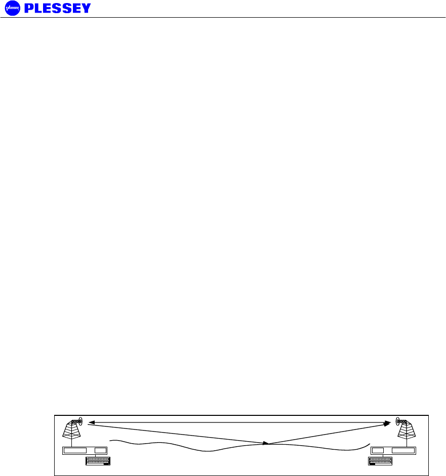
A digital radio link (DRL) consists of a pair of MDR / Orion radio stations.
The radio stations consists of two main parts:
• An RF Unit operating in the 2.4GHz or 5.8 GHz ISM frequency bands. The RF
Unit provides the radio transceiver functionality by accepting radio link data from
the Digital Indoor Unit and converting it to the 2.4GHz or 5.8 GHz ISM frequency
band using spread spectrum or QAM modulation. The received signal is de-
modulated and transmitted to the Digital Indoor Unit in a digital format.
• An Digital Indoor Unit, available with 1, 2, 4 or 8 T1 and 1, 2, 4 or 8 E1 data
interfaces (choice of T1 or E1 is software selectable). The Digital Indoor Unit
combines nT1 or nE1 data with Wayside Service Channel serial data and link IP
data to be transmitted across the radio link. The Digital Indoor Unit also provides
power to the RF Unit.
Interconnection between RF Unit and Digital Indoor Unit is achieved using low cost
data and power cables.
2.2 RF Unit
The MDR2400, MDR5800, Orion2410i and Orion5810i RF Units make use of Spread
Spectrum modulation technology for license-free operation in the 2.4GHz and 5.8 GHz
ISM bands. The Orion5850 RF Unit uses three software selectable bandwidths for
license-free operation in the 5.8 GHz ISM band.
The Orion2410i and Orion5810i RFUs are MDR2400 and MDR5800 RFUs
respectively, that have been repackaged into 1U units that should be used in indoor
unit applications only. Please refer to Appendix K for more detail.
For operation, the ISM bands are divided into upper and lower frequency sub-bands.
A ‘High Band’ RF Unit transmits in the higher frequency sub-band and receives in the
lower frequency sub-band, while a ‘Low Band’ RF Unit transmits in the lower sub-band
and receives in the higher sub-band. An MDR / Orion radio link will use a ‘Low Band’
RF Unit on one end of the link to communicate with a ‘High Band’ RF Unit on the other
end.
The RF Units use a Type-N RF output connector for connection to suitable 2.4GHz
and 5.8GHz antennas for applications where long range is required.
The system is available for use in FCC regulated countries.
User Data
MDR2400, MDR5800 or
Orion 5850 OU
MDR / Orion IU
User Data
MDR2400, MDR5800 or
Orion 5850 OU
MDR / Orion IU
MDR2400/5800-SR, Orion2410/5810-SRi and Orion 5825-SR
862-01881 Issue 12c Page 13
2.2.1 Frequency plans
The MDR5800, Orion5810i and the Orion 5850 RF Units operate in the 5.725 GHz to
5.850 GHz ISM frequency band with predefined frequency channel plans (termed A, B,
C and D). Channel plan D is user selectable / adjustable.
The MDR2400 and Orion2410i RF Units operate in the 2.400 GHz to 2.4835 GHz ISM
frequency band with predefined frequency channel plans (termed A, B and D).
Channel plan D is user selectable / adjustable.
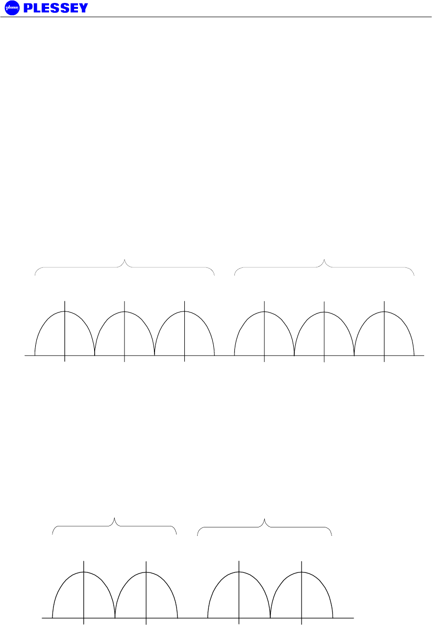
2.2.1.1 MDR5800 and Orion5810i Frequency Channel Plan A, B and C
The channel spacing is based on the bandwidth occupied by the spread spectrum
signal (approximately 17 MHz) and is used to optimise link performance. In the case
of plan A, plan B and C, note that both RF Units of a link must be set up to the same
frequency channel plan (i.e. A, B or C).
C
H
B
H
Frequency (MHz)
LOW BAND TRANSMIT HIGH BAND TRANSMIT
A
H
A
L
B
L
C
L
5735 5753 5771 5804 5822 5840
Figure 1. MDR5800 and Orion5810i Frequency channel plans A, B and C
2.2.1.2 MDR2400 and Orion2410i Frequency Channel Plan A, B (non-FCC)
The channel spacing is based on the bandwidth occupied by the spread spectrum
signal (approximately 17 MHz) and is used to optimise link performance. In the case
of plan A and B, note that both RF Units of a link must be set up to the same frequency
channel plan (i.e. A or B).
A
H
B
H
Frequency (MHz)
LOW BAND
TRANSMIT
HIGH BAND
TRANSMIT
A
L
B
L
2410 2426 2458 2474
Figure 2. MDR2400 and Orion2410i Frequency channel plans A and B
MDR2400/5800-SR, Orion2410/5810-SRi and Orion 5825-SR
862-01881 Issue 12c Page 14
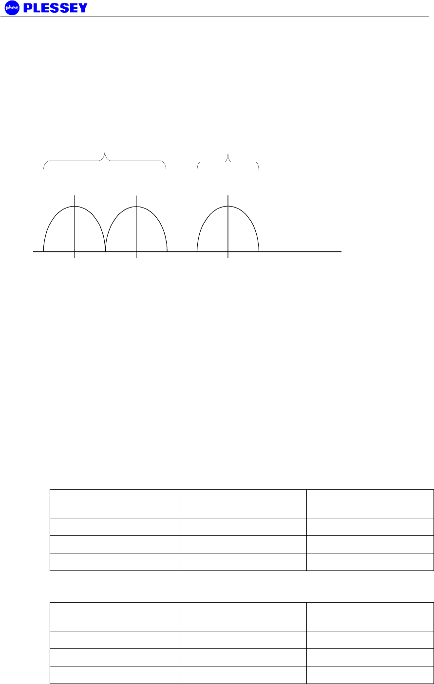
2.2.1.3 MDR2400 FCC Compliant Frequency Channels for the U.S. only
In countries where FCC compliance is required, only the following frequencies may be
used:
Low band RF Unit – 2412MHz to 2426MHz,
High band RF Unit – 2458MHz.
Use frequency plan D (variable frequency) to set the RF Unit.
DH
Frequency (MHz)
LOW BAND TRANSMIT HIGH BAND
TRANSMIT
DLDL
2412 2426 2458
Figure 3. MDR2400 FCC Compliant Frequency Channels for the U.S. only
2.2.1.4 Orion 5850 Frequency Channels Plan A, B and C (FCC Compliant)
The channel spacing is based on the transmit bandwidth, either 3 MHz, 6 MHz, or 10
MHz, software selectable. Different bandwidths can be selected dependent on the
optimum link performance; required system sensitivity versus data transfer rate.
Only channel frequencies that are FCC compliant can be selected through the
configuration software. The channel frequency ranges are programmed into the radio
firmware and cannot be adjusted by the user.
The radios were tested and approved for FCC compliance with the frequency ranges
below, see Figure 4.
Low band RF Unit:
Modulation Type Lowest Center Freq.
(MHz)
Highest Center Freq.
(MHz)
8464kbps / 16-QAM 5731 5774
16928 kbps / 16-QAM 5732 5773
25392 kbps / 16-QAM 5734 5771
High band RF Unit:
Modulation Type Lowest Center Freq.
(MHz)
Highest Center Freq.
(MHz)
8464kbps / 16-QAM 5801 5844
16928 kbps / 16-QAM 5802 5843
25392 kbps / 16-QAM 5804 5841
MDR2400/5800-SR, Orion2410/5810-SRi and Orion 5825-SR
862-01881 Issue 12c Page 15
NOTE 1 Both RF Units in a link must be set to the same frequency channel plan (i.e.
A, B, C or D) and modulator type. Also note that the frequencies differ for different
transmit bandwidths, i.e. the frequency of channel A changes according to the transmit
bandwidth.
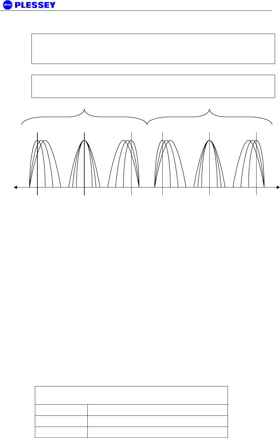
NOTE 2 Figure 4 reflects all the frequency bands that could be obtained with the
ORION5850 RFU. Pre-programmed frequency ranges in the radio firmware prevent
the user from selecting transmission options that will not meet FCC requirements.
Frequency [MHz]
5731 5774 5801 5844
ABCABC
Low Transmit Band High Transmit Band
Figure 4. Orion 5850 Frequency channel plans A, B and C. Refer to NOTE 2 above with
regards to FCC standards compliance of the different band plans.
2.2.1.5 Frequency Channel Plan D (FCC Compliant)
Frequency plan D allows independent control of transmit and receive frequencies.
This allows a flexible frequency plan and can be used to overcome interference in the
2.4GHz and 5.8 GHz ISM bands.
The frequencies that can be used in the lower or upper sub-bands can be selected in
1 MHz increments. Performance degradation can be expected when operating using
channel plan D mode with the chosen frequencies close to the sub-band edges i.e. a
choice of one of the high frequencies in the lower sub-band and one of the lower
frequencies in the upper sub-band.
The allocation of Channel plan D frequencies is shown in Table 4, Table 5 and Table
6.The Orion 5825 has up to three different sets of minimum and maximum
frequencies, which are determined by the data rate setting of the RFU.
Only channel frequencies that are FCC compliant can be selected through the
configuration software. The channel frequency ranges are programmed into the radio
firmware and cannot be adjusted by the user.
The radios ware tested and approved for FCC compliance with the frequency ranges
below, see Figure 4.
Table 4. MDR2400 and Orion2410i Channel plan D channel
frequencies
Sub-band Center Frequency (MHz)
L 2410-2426
H 2458-2474

MDR2400/5800-SR, Orion2410/5810-SRi and Orion 5825-SR
862-01881 Issue 12c Page 16
NOTE the allowable operation range in FCC countries, page 14.
Table 5. MDR5800 and Orion5810i Channel plan D channel
frequencies
Sub-band Center Frequency (MHz)
L 5735-5771
H 5804-5840
Table 6. Orion 5850 Channel plan D channel frequencies
Center Frequency (MHz)
RF BW [MHz] /
Data Rate
[kbps] Lower Sub-band Upper / Higher Sub-band
2.6 / 8464 5731-5774 5801-5844
5.4 / 16928 5732-5773 5802-5843
8.0 / 25392 5734-5771 5804-5841
2.2.1.6 Orion 5850 Modulator Types
The Orion 5850 can operate with different modulator types, the trade-offs being better
radio performance versus higher data throughput. The changes can be made via
software, using either the Orion NMS / GUI or an SNMP client application.
Modulator types and frequency bands that were tested and approved for compliance
with FCC regulations are specified in Sections 2.2.1.4 and 2.2.1.5.
Table 7. Orion 5850 Modulator Types
Data Rate
[kbps]
Modulation
type
Raw data
throughpu
t [bit/sec]
Typical
Payload
Approx. RFU
output spectrum
BW
8464 16-QAM 8 464 052 4T1/E1 +
150kbit
Ethernet
2.6 MHz
16928 16-QAM 16 928 105 8T1/E1 +
150kbit
Ethernet
5.4 MHz
25392 16-QAM 25 392 157 8T1/E1 +
9.5Mbit
Ethernet
8 MHz
NOTE 1: Changing the modulator type of an Orion 5850 RF Unit may take up to 30
seconds. During this period, the link will not be available. Changing the RFU
modulator type does not support Auto Recovery thus; the modulator type of the remote
station must be changed before the modulator type of the local station is changed.
2.2.2 RF Power Output Options
The RF Unit is designed for use in countries that have adopted FCC standards. It is
possible to adjust the output power on the RFU using the supplied NMS software or a
MDR2400/5800-SR, Orion2410/5810-SRi and Orion 5825-SR
862-01881 Issue 12c Page 17
SNMP Management application. The FCC standards for the MDR2400 unit require a
limited output power as stated on page 2, U.S. only.
NOTE 1 The firmware on the Orion and MDR type RFUs will not accept power level
settings that fall outside the FCC compliant levels.
2.2.3 MDR2400, MDR5800, Orion2410i, Orion5810i and Orion 5850 RF Units
The RF Units transmit and receive RF signals through a diplexer interfaced via an RF
cable to an external antenna. The unit has a type-N connector for connection to the
RF cable used between the RFU and the antenna.
The RF Unit houses the following main parts:
a. Transmit/Receive Modules
b. Baseband Modulator/Demodulator Circuitry
c. Microcontroller/Framing & Buffering Circuitry
d. Power Amplifier
e. Diplexer
2.3 MDRMTE, MDRMETU, Orion10 and Orion25 Digital Indoor Unit
The Digital Indoor Unit is designed for mounting in a 19” rack, occupying a 1U slot. It
can also be used as a table-top system.
The Digital Indoor Unit accepts n x T1/nE1 user payload channels and combines it
with Wayside Service Serial Data and IP data to be transmitted across the radio link.
The Digital Indoor Unit is fitted with a DC power supply.
There are four types of Digital Indoor Units:
An MDR 120 Ohm (scalable up to 4 T1/E1),
an MDR 75 / 120 Ohm (scalable up to 4 T1/E1),
an Orion 10 Digital Indoor Unit (Orion 25 with only up to 4 T1/E1)
and an Orion 25 Digital Indoor Unit (scalable up to 8 T1/E1).
The MDRMTE and MDRMETU Digital Indoor Units can operate with the MDR2400,
MDR5800, Orion2410i and Orion5810i RF Units.
The Orion 10 and Orion 25 Digital Indoor Unit is used with the Orion 5850 RF Unit, but
can also support the MDR2400, MDR5800, Orion2410i and Orion5810i RFUs if the
appropriate firmware version is loaded on the Digital Indoor Unit.
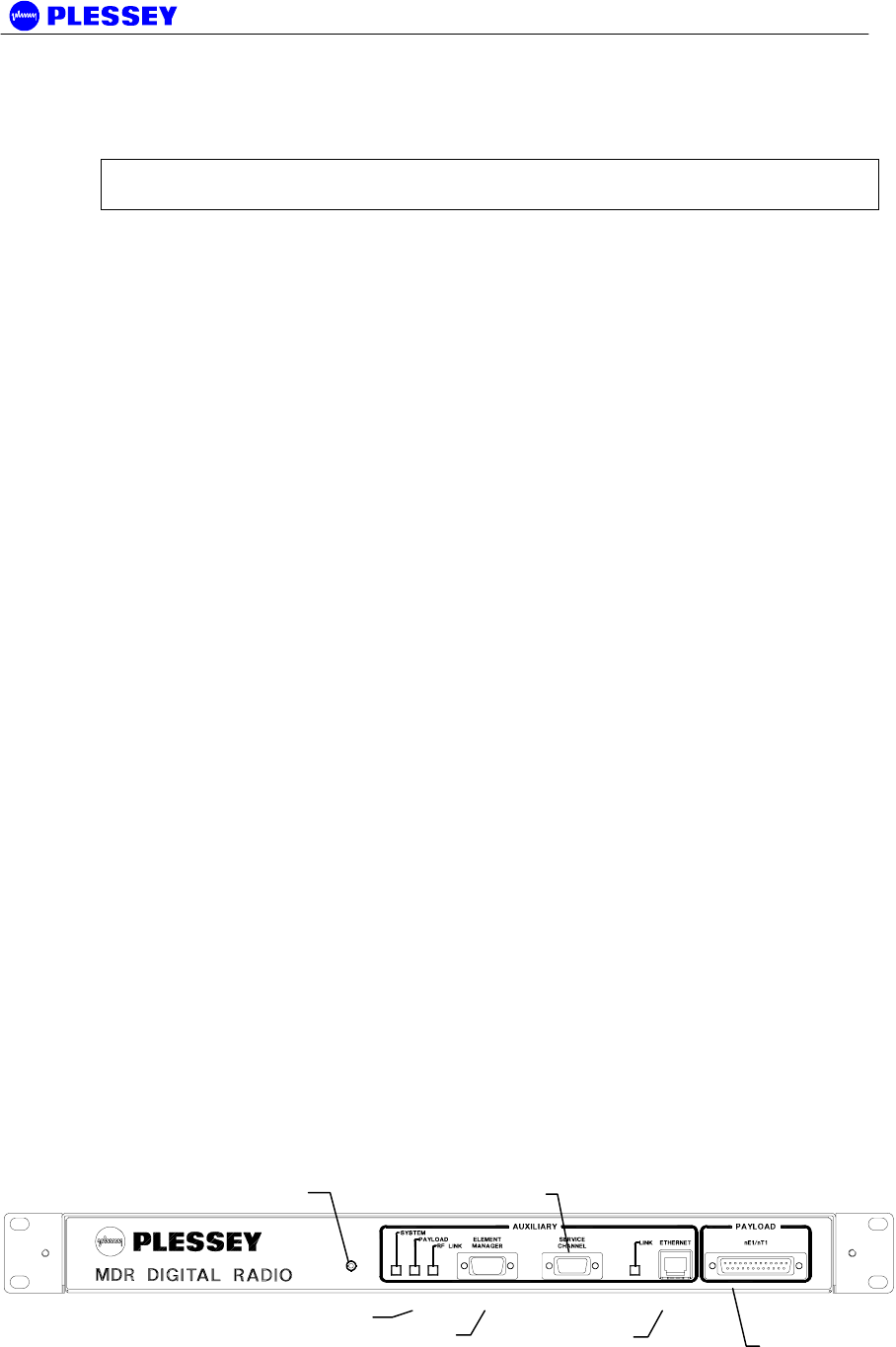
MDR MTE DIGITAL INDOOR UNIT V2, 120 OHM 651-03810-02.1, front panel
1 Payload
T1/E1
2 DIU
Status
LED
3 Reset
button 4
56 10BaseT
RJ45 Socke
t
MDR2400/5800-SR, Orion2410/5810-SRi and Orion 5825-SR
862-01881 Issue 12c Page 18
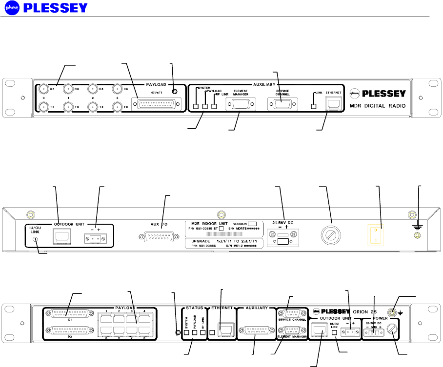
MDR MTE 75/120 OHM DIGITAL INDOOR UNIT 651-04008-02, front panel
MDR MTE 120 OHM and 75/120 OHM DIGITAL INDOOR UNIT, rear panel
Orion 25 DIGITAL INDOOR UNIT 651-04189-01 (front panel – no rear panel connectors)
Figure 5. Digital Indoor Unit Connector Panels.
2.3.1 Payload Interface Options
The Digital Indoor Unit can be configured for nT1 or nE1 operation.
• 1, 2, 4 or 8(Orion 25) x T1 (1.544 Mbps)
• 1, 2, 4 or 8(Orion 25) x E1 (2.048 Mbps)
For T1 connectivity, bipolar AMI or B8ZS line coding is software selectable.
For E1 connectivity, bipolar AMI or HDB3 line coding is software selectable.
Line coding on the Orion 25 DIU may be selected separately for tributary channels 1 to
4 and 5 to 8 when used with an Orion 5850 RFU.
The payload can be connected on:
• Unbalanced 75 Ohm BNC connectors, 75/120 Ohm DIU only (RX= In, TX= Out).
• Balanced 120 Ohm, 25 way D-type connectors (refer to paragraph 4.2.4 for the
pin outs).
• Balanced RJ48C connectors (refer to paragraph 4.2.5 for the pin outs).
1 Payload
T1/E1
2 DIU
Status
LEDs
2 DIU Status
LEDs
3 Reset
button
3 Rese
t
button
9 RFU
DC Out
9 RFU DC
Out
4
4
5
56 10BaseT
RJ45 Socket
6 10BaseT
RJ45 Socket
7
7
8 DDIU/RFU
Data RJ45
8 DDIU/RFU
Data RJ45
10 Auxiliary IO
10 Auxiliary IO
11
DIU
D
CIn
11 DIU DC In
12
Fuse
12
Fuse
13 ON/OFF
Switch
14 Ground
Terminal
14 Ground
Terminal
1 Payload
T1/E1

MDR2400/5800-SR, Orion2410/5810-SRi and Orion 5825-SR
862-01881 Issue 12c Page 19
NOTE A special version of the MDR Digital Indoor Unit exists that allows the user to
select AMI or B8ZS line encoding on a per-trib basis for T1 connectivity. These Digital
Indoor Units are marked as Version 2.1AT and are identified by an “Individual Line
Code” label between the ON/OFF switch and the ground terminal on the rear panel of
the DIU.
Line codes can be selected on a per-trib basis using the Orion NMS software
application. In the Payload Configuration window:
1. Set the Digital Indoor Unit Payload interface to T1 mode and Apply.
2. Refresh the information displayed in the window.
3. Select the desired Line Code next to each trib and Apply.
Hardware modified to implement this feature can ONLY work with special DIU
firmware – contact the distributor for details.
2.3.2 1+1 Redundancy Protected Payload System
The MDR and Orion radios can be used in a 1+1 redundant mode system to protect
the tributary payload data carried over a radio link. This system detects the quality of
the link over which it is receiving data and allows switching between two parallel radio
links to protect the user data against link failures.
Please refer to Appendix I, or the Protection Kit user manual, doc. no. 862-02236 for
detail on the functioning of this system.
2.3.3 Digital Indoor Unit Status LEDs
The Digital Indoor Unit LED functionality is described as follows:
SYSTEM
Green OK, Orange (RFU/DIU Comms Error), Red (RFU/DIU Comms Down)
PAYLOAD
Green OK, Orange (AIS Detected), Red (LOS Detected)
RF LINK
Green OK, Orange (FEC Correcting Errors), Red (FEC unable to correct errors)
In ALL cases flashing red and orange LEDs imply historic alarm conditions (The alarm
can be cleared using the front panel button ‘position 1’ : see next section).
Flashing LED’s and yellow indicators (Orion NMS) may also be cleared by clicking on
the “Clear Alarms” button in the Orion NMS Main Radio Window.
2.3.4 Reset / Configuration Button
The functionality of the Reset Button is described below. These functions are used to
set up the radio. A paper clip or similar “probe” can be used to push the “reset /
configuration button”. The count value / LED count at which the button is released, will
be the "new" configuration / state of the DIU.

MDR2400/5800-SR, Orion2410/5810-SRi and Orion 5825-SR
862-01881 Issue 12c Page 20
The count value is determined by the different LEDs lighting up. ‘Position 1’ being RF
Link LED (Green), 2 being Payload LED (Green), 3 being System LED (Green), 4
being RF Link LED (Orange), 5 being Payload LED (Orange) and 6 being System LED
(Orange) etc.
Reset button functions (according to "LED reset" number)
1. Clear Front Panel LEDs (and associated alarms in DIU)
2. Clear Event Log in the Digital Indoor Unit
3. Reset the Digital Indoor Unit (does not reset the non-volatile memory storing the
DIU’s configuration parameters)
4. Routed Configuration: Reset the DIU configuration parameters that are stored in
non-volatile memory (BATTERY-BACKED STATIC RAM) and configure as a ‘Far
Side DIU’ : i.e. for a ROUTED IP configuration, set the Ethernet IP address as
10.11.1.2, Element Manager IP address to 10.12.1.2
5. Routed Configuration: Reset the DIU configuration parameters that are stored in
non-volatile memory and configure as a ‘Near Side DIU’ : i.e. for a ROUTED IP
configuration set the Ethernet IP address as 10.2.1.2, Element Manager IP
address to 10.13.1.2
6. Routed Configuration: If you are not sure how the DIU is configured (NEAR or FAR
side DIU), reset it AS IS i.e. reset the ‘Near Side DIU’ or ‘Far Side DIU’
configuration parameters depending on how the DIU is currently configured.
7. Bridged Configuration: Reset the DIU configuration parameters that are stored in
non-volatile memory (BATTERY-BACKED STATIC RAM) and configure as a ‘Far
Side DIU’ For a BRIDGED IP configuration, see Appendix C of this document for a
description of the default IP addresses.
8. Bridged Configuration: Reset the DIU configuration parameters that are stored in
non-volatile memory and configure as a ‘Near Side DIU’. For a BRIDGED IP
configuration, see Appendix C of this document for a description of the default IP
addresses.
9, 10, 11 RESERVED
12. Set up Digital Indoor Unit with E1 tributaries.
13. Set up Digital Indoor Unit with T1 tributaries.
14. Deactivate buttons 4 onwards.
15. Toggle SNMP and FTP Servers ON/OFF (V3.00+ firmware)
16. DHCP ON (V3.00+ firmware)
17. DHCP OFF (V3.00+ firmware)
18. Ethernet MAC learning enabled via front panel
19. Transparent ethernet mode enabled via front panel
20. EEprom erased via front panel (MDR Only)
21. RFU back-to-back enable / disabled toggle via front panel
NOTE All buttons can be REACTIVATED (i.e. undoing a 14 'reset') by doing a power-
on reset while holding the front-panel Reset Button in for 1 LED count.
MDR2400/5800-SR, Orion2410/5810-SRi and Orion 5825-SR
862-01881 Issue 12c Page 21
NOTE
POSITIONS 4, 5, 6, 7 and 8 RESET THE DIGITAL INDOOR UNIT TO FACTORY DEFAULTS –
THESE RESETS ARE TYPICALLY ONLY USED ONCE (THESE CHOICES RESET CERTAIN
ADJUSTABLE PARAMETERS IN NON-
V
OLATILE MEMORY IN THE DIGITAL INDOOR UNITS).
IF CHANGES ARE MADE TO THE CONFIGURATION PARAMETERS AND THE USER DOES
NOT WANT THESE TO CHANGE WHEN A UNIT IS RESET, THE DIGITAL INDOOR UNIT CAN
BE POWER-CYCLED OR POSITION ‘3’ MUST BE USED E.G. THIS TECHNIQUE IS USED IF
THE IP ADDRESSES ASSOCIATED WITH THE NETWORK INTERFACES ARE ADJUSTED –
THE PROCESSOR NEEDS TO BE RESET TO ALLOW THE CHANGE/S TO BE IMPLEMENTED.
IF YOU OVER-RUN THE SELECTION YOU REQUIRE, CONTINUE UNTIL THE LEDs GO
BLANK – THEN, START AGAIN (OPTION AVAILABLE WITH RELEASE 2+ OF DIU
FIRMWARE).
2.3.5 Service (Wayside) Serial Data Channel
This port supports asynchronous full duplex, serial data transfer at a speed of 115200
bps.
The interface type is RS-232 configured as DCE (Data Communications Equipment).
Handshaking can be None, Hardware.
2.3.6 Element Manager Port
This port is used for communication with the NMS software or with an SNMP manager
to control the MDR system. The port must be connected to a serial port (configured
for a speed of 115200 bps) on a personal computer to use the NMS software.
The interface type is RS-232 configured as DTE (Data Terminal Equipment).
Hardware handshaking is used.

MDR2400/5800-SR, Orion2410/5810-SRi and Orion 5825-SR
862-01881 Issue 12c Page 22
2.3.7 10BaseT Ethernet RJ45 Port
This port is used for communications with the NMS / GUI software from a laptop / PC
or with an SNMP manger to control the system. It can also be connected to a hub for
10BaseT wayside Ethernet throughput.
The interface type is DTE (Data Terminal Equipment) and can support Full and Half
Duplex Ethernet connections. Select the Ethernet Duplex mode from the following
MIB element: 1.3.6.1.4.1.1316.1.1.1.4.16 mdrmteEthernetFullDuplex.
Take note that connecting the radio to an Ethernet hub requires the Ethernet interface
to operate in Half Duplex mode.
2.3.8 DIU/RFU Link LED
This LED indicates if there is a suitable electrical connection between the Indoor and
RF Units1.
2.3.9 DIU/RFU Data Interconnect RJ45
This receptacle accepts an RJ45 plug that connects to UV-protected STP (Screened
twisted pair) cable used between the DIU and the RFU.
2.3.10 DIU/RFU Power Interconnect
This connector (socket) is used for power interconnection between the DIU and the
RFU. The connection is made using UV-protected 2-core cable. The cable is
connected to a GREEN, two-pin connector, a plug.
CAUTION
The polarity sense (labelled) must be maintained between the DIU and the RFU.
2.3.11 Auxiliary In/Out Port
The auxiliary in/out port is used for remote monitoring and control. The following are
provided
• Two inputs (for sensing contact closure or opening) are provided to sense site
alarm inputs. The states of these alarm inputs can be monitored with NMS, as
well as from an SNMP Management Station.
• Two relay contact outputs, normally-open and normally-closed contacts, are
provided as alarm / auxiliary outputs. Output states are software customised and
controlled. The outputs are used to indicate alarm or other states selected by the
operator via the NMS or a SNMP Management Station.
1 NOTE that on V1 hardware only the Ethernet Physical interface is checked with this LED, not the
RS232/485 interface. The integrity of the RS232/485 interface is checked using the front panel
“System LED”. On later versions the RS232/485 interface is no longer used.

MDR2400/5800-SR, Orion2410/5810-SRi and Orion 5825-SR
862-01881 Issue 12c Page 23
2.3.12 DIU DC Power Input
This connector (socket) is used for power input to the DIU. The connection is made
using 2 or 3-core cable. The cable is connected to a two pin GREY connector on the
MDR radio and a THREE pin GREEN connector on the Orion unit - both are plugs.
The polarity-sense (labelled) must be observed and implemented. A ground
connection is available on the three-pin connector. This ground connection is not
required if the ground terminal is connected (2.3.15).
2.3.13 Fuse Holder
This holder is used to hold a fuse (2A, slow blow fuse).
2.3.14 ON/OFF Switch
This switch is used to control power input to the Digital Indoor Unit (and indirectly the
RF Unit). No switch is fitted to the Orion DIU. The unit will start up as soon as the
required DC voltage is applied.
2.3.15 Ground Terminal
This is used to accept connection to an earth strap, terminated with a crimped earth
lug. Refer to the installation chapter for details on wire/earth lug requirements. A
ground connection is also available on the three-pin DIU DC power connector.
MDR2400/5800-SR, Orion2410/5810-SRi and Orion 5825-SR
862-01881 Issue 12c Page 24
3 Planning
This chapter is aimed at management and planning staff to enable them to assess the
requirements for installing an MDR / Orion digital radio link.
3.1 System Type Selection
The system uses an RF Unit with a type-N RF output for connection to a range of
antennas.
The MDR / Orion is aimed at FCC regulated markets.
Antenna polarization can used to co-locate multiple systems.
Antenna polarization can be used to overcome interference.
3.1.1 Antenna selection
The antenna type must be selected before the system is to be installed. The chosen
antenna must enable the system to operate with sufficient link fade margin without
excessive cost and allow the user’s ‘link availability requirements’ to be met.
The main consideration when selecting an antenna is antenna gain measured in dBi.
A path loss analysis is highly recommended to determine the antenna gain needed for
adequate fade margin. The table below shows antenna selection guidelines for some
configurations. The distances are calculated for a 20 dB link fade margin.
To reduce potential radio interference to other users, the antenna type and its gain
should be so chosen that the equivalent isotropically radiated power (EIRP) is not
more than that required for successful communication.
Table 8 MDR5800 Antenna Selection
Antenna Type Gain (dBi) MDR RFU
Typical
Distance (Km)
Power level (dBm)
0.15 m Flat panel 18 9 24
0.3 m Flat panel 24 30 24
0.6 m Flat panel 28 80 24
Table 9 Orion5810i Antenna Selection
Antenna Type Gain
(dBi)
MDR RFU
Typical Distance
(Km)
Power level
(dBm)
Gabriel Parabolic
Antenna
(SSP 52B)
29 80 25

MDR2400/5800-SR, Orion2410/5810-SRi and Orion 5825-SR
862-01881 Issue 12c Page 25
Table 10 Orion5850 Antenna Selection
Antenna Type Gain (dBi) MDR RFU
Typical
Distance (Km)
Power level (dBm)
0.6 m Flat panel
(MT-20004)
28 80 24
Table 11 MDR2400 and Orion2410i Antenna Selection
Antenna Type Gain (dBi) Distance (Km) Power level (dBm)
1.2 m Parabolic
Antenna
27 80 18
MDR2400/5800-SR, Orion2410/5810-SRi and Orion 5825-SR
862-01881 Issue 12c Page 26
3.2 Site Evaluation
When planning a site for a digital radio link, it is of the utmost importance that you take
the operational environment of the proposed site into account.
The combined effect of atmospheric environmental factors such as rain and lightning,
atmospheric attenuation, signal path obstruction, propagation fading, air temperature
gradients, ice build-up, wind and solar radiation can contribute towards reducing the
level of performance of the system. The 2.4 GHz and 5.8 GHz bands are not adversely
affected by rain, ice or snow. Severely cold and excessively warm climatic conditions
outside the scope of the operating temperature range can affect the function of the
system, especially the outdoor equipment (see Environmental Characteristics on page
50 of this manual).
Also, if masts are not sufficiently rigid, very strong winds can affect the antenna beam
alignment and Outdoor equipment reliability due to wind force build-up and/or vibration
of the mast-mounted equipment.
3.3 Multipath Effects
The effects of multipath propagation can influence the radio. Understanding these
effects will help when installing a radio link and maximise the reliability of the link.
Multipath fading occurs when the receiving antenna receives not only the direct signal
from the transmitting antenna but also a signal from the transmitting antenna that has
reflected off the ground or nearby obstacles. The reflected signal takes a longer path to
reach the receiver and acts as interference since it is not in-phase with the direct path
signal. The amplitude of the interference can be almost equal to that of the direct path
signal, thus degrading the performance of the link.
Multipath propagation is dependent on transmit frequency and the specific geometry of
the link such as antenna heights, distance between the antennas and the local terrain.
To counteract multipath propagation, the installer can change the frequency at which
the link operates or adjust the height of one or both of the antennas.
Figure 6. Multipath Effects.
User Data
MDR / Orion OU
M D R / O rion IU
U s e r D a ta
MDR / Orion OU
MDR / Orion IU
D ire c t R F P a th
R e fle c tio n P a th

MDR2400/5800-SR, Orion2410/5810-SRi and Orion 5825-SR
862-01881 Issue 12c Page 27
3.4 Interference Considerations
The ISM frequency bands are used by other devices that can cause interference to the
MDR / Orion radio systems. Interference can be avoided by careful planning of the
system installation. The available methods for providing isolation from interfering
radiators are the following:
• Frequency diversity
• Antenna polarization
It is recommended to scan the proposed installation areas with a spectrum analyzer
prior to installation to establish the presence of interference. The spectrum analyzer
feature available on the NMS / GUI may also be used. If interference is detected on
the path, the GUI, via laptop connection, can be used to select a new channel plan (A,
B, or C) to “steer around the interferer, or to create a new custom channel plan (Plan
D) to avoid the interference. SNMP network architecture, if employed, may also be
used to make the frequency plan changes. The frequency spectrum should be
scanned over a sufficient time period to ensure that periodic transmissions are
recorded.
Interferers will cause problems if their amplitudes are not more than 20 dB below the
intended receive power level. A link path loss calculation should be performed to
determine the expected receive power level.
The procedure for selecting the optimum antenna polarization and system frequency
plan is the following:
• Perform a spectral analysis at each site in the link direction using a high gain
antenna.
• Repeat the spectral analysis for vertical and horizontal polarization.
• Select the polarization with the lowest interfering levels as the system antenna
polarization.
• Consult the MDR / Orion frequency channel plans as shown in section 2.2.1 and
select the frequency plan that would operate in an interference-free band.
• Install the ‘High Band’ and ‘Low Band’ RF Units at the sites where they would
experience the lowest interference in their respective receive bands.

MDR2400/5800-SR, Orion2410/5810-SRi and Orion 5825-SR
862-01881 Issue 12c Page 28
3.5 Microcell Backhaul Applications of MDR / Orion Digital Radios
In applications where more than one independent and separate links, need to radiate
from a central site, a number of parameters can be taken advantage of, to provide
isolation and minimise interference between these links:
• Frequency multiplexing
• Antenna polarization
• Choice of High Antenna Gain
It is important to note that these methods only provide isolation between two radio
Systems, and that power levels in the separate systems should be balanced to ensure
correct operation.
3.5.1 Setting the Transmitted Power Levels
To minimise interference, received power levels should be balanced between separate
radio links. This means that transmit power levels should be set to provide similar
levels of received power, as indicated by the RSSI values of the adjacent receivers at
the central site. Power levels are easily adjusted via point and click selection utilizing
the provided NMS / GUI, installed on your laptop or via SNMP network architecture.
3.5.2 Frequency Multiplexing
The MDR2400 and Orion2410i offers three frequency channel plans, the MDR5800
and Orion5810i four and the Orion 5850 also four. Refer to paragraph 2.2.1 for more
detail on the frequency channel plans. A radio link requires two channels (one for
transmit and one to receive) to provide full duplex operation. Each radio has a high
and a low sub-band, one that it uses for transmission and another for reception.
Terminology definition: the ‘High-band RF Unit’ of a system transmits on the higher of
the two sub-bands. The ‘Low-band RF Unit’ of a system transmits on the lower of the
two sub-bands. A system (link) always has one High Band and one Low Band RF
Unit. It is important to note that unwanted transmitted signals in adjacent frequency
bands can affect other receivers operating in an adjacent band if insufficient antenna
isolation is provided. A solution is to group high-band or low-band RF Units at the
central site, rather than group high and low-band RF Units together.
3.5.3 Antenna Isolation
Separate links at a central site will have sufficient isolation when radio systems
operate outside the radiation beamwidth or side lobes of the system antenna. The
achievable isolation can be established by examining the measured radiation patterns
of the system antennas. Directional isolation can be used if the antenna radiation is
15 dB or lower relative to the adjacent main beam. Antennas with high directionality
will allow reduced angular separation of adjacent systems. Antenna cross-polarization
isolation can be used for adjacent radio links, radiating in the same direction. Typical
isolation of 30 dB can be achieved using high quality antennas.

MDR2400/5800-SR, Orion2410/5810-SRi and Orion 5825-SR
862-01881 Issue 12c Page 29
4 Installation
This chapter describes a recommended installation procedure for the MDR2400,
MDR5800, Orion2410i, Orion5810i and the Orion 5850.
Before installation / departure to site
1. Carefully open all shipping boxes and look for any obvious damage that might
have resulted during shipment.
2. Do an operational bench test to verify the functionality of the system.
3. Confirm that both radios have the correct IP configuration (refer to page 108,
paragraph C.2) for "local" and "remote" sites. Use the provided NMS / GUI
installed on a laptop / PC to configure / analyze the radio via a serial / ethernet
connection to the DIU element manager port. Local and remote IP addresses
labels may be fitted to the DIU’s and can be verified with those listed in the GUI.
4. Both radios should be on the same channel plan (paragraph 2.2.1) and power
should be set to an appropriate test level (not muted).
5. NOTE Use at least 60dB attenuation when directly connecting two RFU RF ports.
6. After initial power up and a minute or so of “settle time”, clear any flashing LEDs
via the front panel reset button (paragraph 2.3.4) or the GUI. The DIU status
LEDs should be green with no errors indicated and remain green for an
appropriate time span (at least 1-2 minutes).
7. After satisfactory results, disconnect the units and transfer to the installation site
for permanent installation.
NOTE It is recommended that the installer have previous experience in installing radio
communication equipment or has attended a training course from the supplier for the
purpose of understanding how to set-up and configure an MDR / Orion radio.
Recommended installation procedure
1. Install the Digital Indoor Unit.
2. Prepare and connect the cables to the Digital Indoor Unit.
3. Install the RF Unit and antenna.
4. Install the Indoor-to-RF Unit interconnection cables (the power and data cables).
5. Turn the Digital Indoor Unit power on.
6. Perform the initial software setup using the supplied NMS application
7. Repeat item 1-5 for the remote site.
8. Align the antennas (use the RSSI voltage on the RFU or the RSSI value from the
MIB or the NMS Graphic User Interface to assist with the setup).
9. Perform a functional test and commission the link.
10. Connect to user data.
11. Start the system.
Installation of the MDR / Orion elements are described in the following sections:
• Installing the Digital Indoor Unit
• Installing the RF Unit and Antenna
• Installing the interconnection cables

MDR2400/5800-SR, Orion2410/5810-SRi and Orion 5825-SR
862-01881 Issue 12c Page 30
4.1 Customer Furnished Tools and Equipment
The following table lists tools and equipment required to install the MDR2400-SR,
MDR5800-SR, Orion2410-SRi, Orion5810-SRi and the Orion 5825-SR system.
General, DIU-to-RFU Interconnect
• Cable cutting and stripping tools.
• Ground lug crimp tools.
• 3 mm flat screwdriver - DIU to RFU power cable.
• RJ45 crimp tool - DIU to RFU data cable.
• Soldering iron.
• Ground cable or strap rated at 45A with 5 mm ground lug for grounding the Indoor
and RF Units.
• Cable ties, used to secure the cables to the mast at regular intervals.
DIU
• Pozi #2 screwdriver - DIU mounting in a 19" rack and the ground lug.
• 7mm Spanner – Attaching the earth cable to the DIU.
• 2.5mm Allen key - To change the position of the DIU mounting brackets.
• DC power supply cable: minimum 2.5 mm square conductor, rated for 10 A. For
connection between the power supply and the Digital Indoor Unit DC connector on
the rear panel. (The DC connector is on the front panel of the Orion DIU.)
• DIU ground lug: 10-4 (10 square mm for wire and hole big enough for M4 thread)
Outdoor RFU
• 13 mm wrench / spanner – used for attachment of RFU to mounting bracket and
mounting bracket to pole. Also used to close RFU with hinge type connection box.
• 2.5 mm Allen key - used to tighten RFU connection box cover fasteners.
• RFU ground lug: 10-8 (10 square mm for wire and hole big enough for M8 thread)
• Multimeter (recommended) to measure RSSI at RFU during antenna panning.
The RSSI level may also be read from the NMS / GUI via laptop connection to the
DIU, indoors
Indoor RFU
• Pozi #2 screwdriver - DIU mounting in a 19" rack and the ground lug.
• 7mm Spanner – Attaching the earth cable to the DIU.
• 2.5mm Allen key - To change the position of the DIU mounting brackets.
• RFU ground lug: 10-8 (10 square mm for wire and hole big enough for M8 thread)
• Multimeter (recommended) to measure RSSI at RFU during antenna panning.
The RSSI level may also be read from the NMS / GUI via laptop connection to the
DIU, indoors

MDR2400/5800-SR, Orion2410/5810-SRi and Orion 5825-SR
862-01881 Issue 12c Page 31
Please refer to paragraphs 4.3.1 and 8.5.10 for details on the RF and data cables,
which are also customer furnished equipment.
4.2 Digital Indoor Unit
4.2.1 Introduction
This section describes the recommended installation procedure for the Digital Indoor
Unit. The Digital Indoor Unit is designed for mounting in the DIN 41494 (19") racking
standard and occupies a 1U high slot. Desktop mounting is also possible.
The Digital Indoor Unit’s payload (nT1, nE1 and 10BaseT Ethernet) and Service
Channel (‘Wayside serial’) data interfaces and Element Management interface are
located on the front panel. Input Power, Auxiliary alarm and ‘DIU/RFU Interconnect’
interfaces are located on the rear panel for the MDR DIU, suitable for rack installations
and on the front panel for the Orion DIU, simplifying accessibility.
The recommended installation procedure for the Digital Indoor Unit is the following:
1. Install the Digital Indoor Unit in the rack.
2. Ground the Digital Indoor Unit. This is required for safety and to minimise radiated
emissions.
3. Connect the DC power supply. There is no ON/OFF switch on the Orion DIU, thus
connecting the DC power supply will start up the radio.
4. Connect Payload data ports (front panel).
5. Connect Auxiliary In/Out port (optional).
6. Connect Service Channel (Wayside) serial port (optional).
7. Connect the Element Manager port using the supplied cable (front panel).
4.2.2 Installing the Digital Indoor Unit in a Rack
1. Slide the Digital Indoor Unit into the 19" rack and secure to the rack using four (4)
APPROPRIATELY sized bolts for size and rack threads provided. M6 x 18 mm
screws are recommended.
2. Ground the Digital Indoor Unit by connecting the ground cable or strap between
the station ground and the ground terminal on the Digital Indoor Unit rear / front
(Orion) panel.
MDR2400/5800-SR, Orion2410/5810-SRi and Orion 5825-SR
862-01881 Issue 12c Page 32
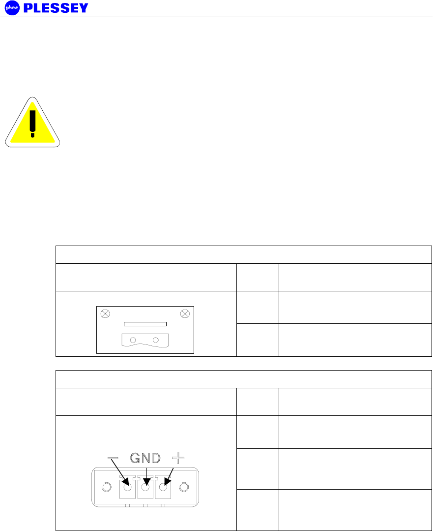
4.2.3 Connecting a DC Power Supply
WARNING – See section 8.4 for specification of the power
supply.
1. Observing the polarity of the supply, wire up the supplied power connector cable
plug and connect it to the DC supply (Voltage range as indicated on the Digital
Indoor Unit) through a minimum 2 A slow blow circuit breaker.
2. Check the supply voltage using a multimeter.
3. Secure the connector screws to the unit.
DC Power Connector Pinouts (MDR DIU)
Digital Indoor Unit connector:
GREY
Pin
No
Signal
+
DC POWER
2-pin Wieland Type 8213 Socket
-+
DC
-
DC POWER RETURN
DC Power Connector Pinouts (Orion DIU)
Digital Indoor Unit connector:
GREEN
Pin
No
Signal
+
DC POWER
GND GROUND PIN
3-pin Phoenix Type 18.27.87.1
Socket
-
DC POWER RETURN
MDR2400/5800-SR, Orion2410/5810-SRi and Orion 5825-SR
862-01881 Issue 12c Page 33
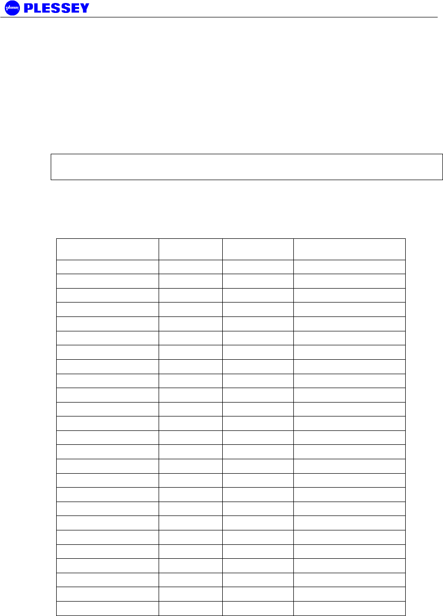
4.2.4 Balanced Payload Data : DB25
1. Assemble the (nE1) / (nT1) payload data input and output cable. See the table
below for Digital Indoor Unit connector pin assignments.
2. Connect the payload data cable to the DB25 connector on the front panel of the
Digital Indoor Unit.
Standard termination of this port is 120 Ohms. On the Orion 25, 75 Ohms termination
is available on request (please contact the factory).
NOTE Rx implies IN (signal expected to go INTO the interface), Tx implies RFUT
(signal coming out of the interface)
Tribs 1-4 are connected on D1 on the Orion10, Orion25 and MDR DIU. In a similar
fashion tribs 5-8 are connected on D2 for the Orion 25 radio, that is pin 2 = RTIP6, pin
10 = RTIP5 and so on.
D-Type Payload Data
Connector Pin #
Pin Name Tributary Direction
1 GND / Earth N/A
2 RTIP2 2 RX +
3 RRING2 2 RX -
4 GND / Earth N/A
5 TTIP2 2 TX -
6 TRING2 2 TX +
7 GND / Earth N/A
8 GND / Earth N/A
9 RRING1 1 RX +
10 RTIP1 1 RX -
11 GND / Earth N/A
12 TRING1 1 TX -
13 TTIP1 1 TX +
14 TRING3 3 TX -
15 TTIP3 3 TX +
16 GND / Earth N/A
17 RRING3 3 RX+
18 RTIP3 3 RX-
19 GND / Earth N/A
20 TTIP4 4 TX-
21 TRING4 4 TX+
22 GND / Earth N/A
23 RTIP4 4 RX+
24 RRING4 4 RX-
25 GND / Earth N/A
MDR2400/5800-SR, Orion2410/5810-SRi and Orion 5825-SR
862-01881 Issue 12c Page 34
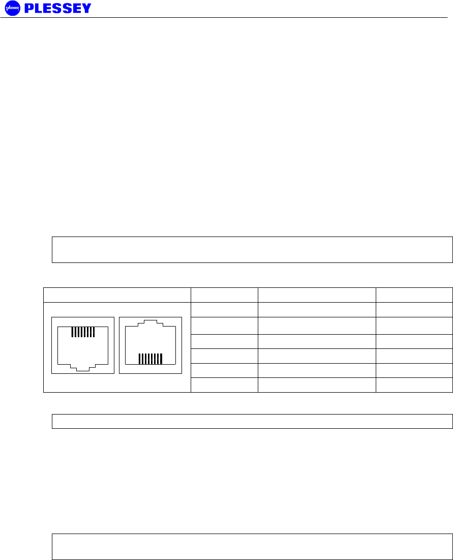
4.2.5 Balanced Payload Data : RJ48
1. Assemble the T1 / E1 payload data input and output cable. See the table below
for Digital Indoor Unit connector pin assignments.
2. Connect the payload data cables to the RJ48 connectors (numbered 1-8 for tribs
1-8) on the front panel of the Digital Indoor Unit.
Standard termination of this port is 110 Ohms. On the Orion10 and Orion25, 75 Ohms
termination is available on request (please contact the factory).
It is recommended to use a cable that connects to pin 1,2,4, and 5 only since the other
pins on the RJ48 are not used to transfer data.
NOTE Rx implies IN (signal expected to go INTO the interface), Tx implies RFUT
(signal coming out of the interface)
RJ48C Socket Pin Description Direction
1 R (Ring 1) TX
2 T (Tip 1) TX
3,6 50 Ohm terminated N/A
4 R1 (Ring) RX
5 T1 (Tip) RX
1 8
1 8
7,8 No Connection N/A
NOTE Use Twisted Pair Cable conductors for pins: 1 & 2, 3 & 6 and 4 & 5.
4.2.6 Unbalanced Payload Data : BNC
One of the variants of the MDR Digital Indoor Unit has a set of 75 Ohm BNC’s on the
front panel as well as the DB25 connector.
• Rx implies IN (signal expected to go INTO the interface)
• Tx implies RFUT (signal coming RFUT of the interface)
NOTE Tribs are numbered 0-3 on the front panel, but are called 1-4/1-8 in the NMS /
GUI.
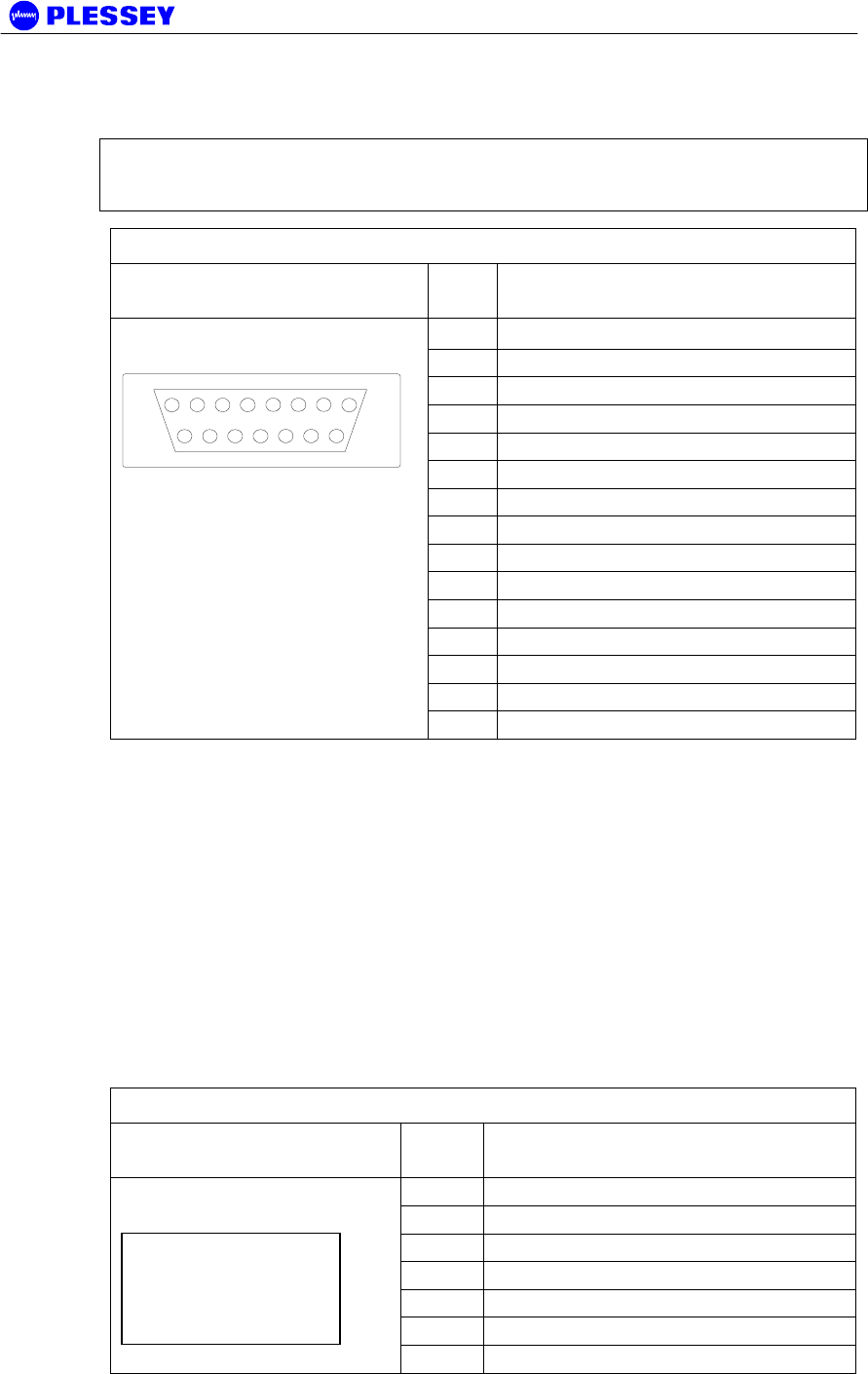
4.2.7 Connecting Auxiliary In/Out (Optional)
The auxiliary in/out port is used to:
• Monitor switch-closure events using two isolated inputs.
• Control line connections using normally-open and normally-closed relay outputs.
Connect the port:
1. Assemble an auxiliary in/out cable using a 15 way D-type male connector
according to connector pin assignments shown in Table 12.
MDR2400/5800-SR, Orion2410/5810-SRi and Orion 5825-SR
862-01881 Issue 12c Page 35
2. Connect to the cable Digital Indoor Unit auxiliary in/out connector.
3. Secure the connector using locking screws.
NOTE The Orion and MDR Digital Indoor Units are equipped with only two relays.
The Normally-Open and Normally-Closed output for each of the two relays are
however provided on the Auxiliary Connector for convenience.
Table 12. Auxiliary In/Out Connector Pin Outs
Digital Indoor Unit
connector
Pin
No
Signal
1 OUTPUT 1 COMMON
2 OUTPUT 1 NORMALLY-OPEN
3 OUTPUT 1 NORMALLY-OPEN
4 OUTPUT 1 NORMALLY-CLOSED
5 OUTPUT 1 NORMALLY-CLOSED
6 OUTPUT 1 COMMON
7 OUTPUT 2 COMMON
8 OUTPUT 2 COMMON
9 OUTPUT 2 NORMALLY-OPEN
10 OUTPUT 2 NORMALLY-OPEN
11 OUTPUT 2 NORMALLY-CLOSED
12 INPUT 1
13 INPUT 1 RETURN
14 INPUT 2
15-pin D-type female
1
8
9
15
15 INPUT 2 RETURN
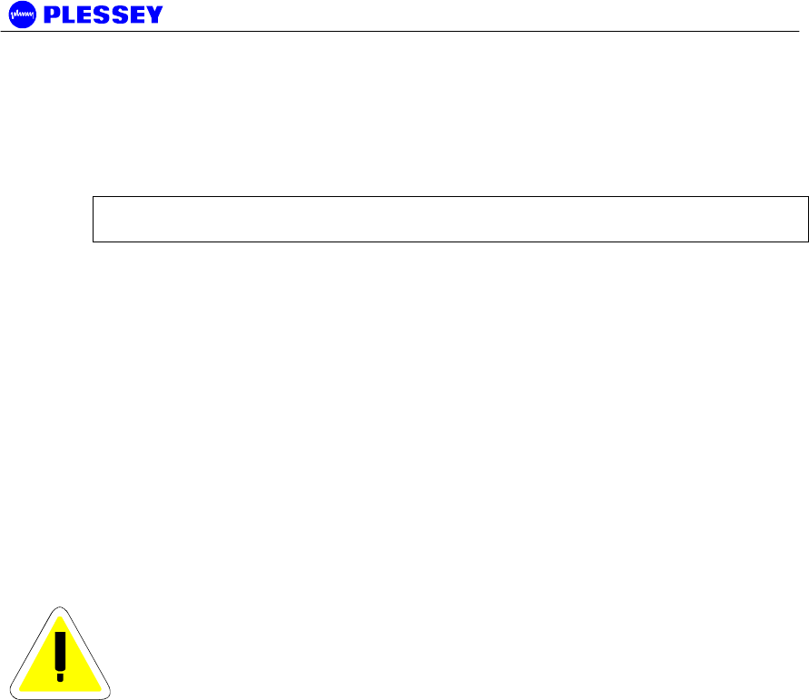
4.2.8 Connecting the Service (Wayside) Serial Channel (Optional)
This ‘clear’ serial channel can transport up to 115,200 bps across the radio link. This
channel does not interfere with the payload data channels. The port is configured as
DCE.
1. Connect the serial data interface cable to the Service channel connector on the
Digital Indoor Unit rear panel. The supplied serial data cable can be used to
connect to this port after the software setup is completed.
2. See the table below for Digital Indoor Unit connector pin assignments when a
custom cable needs to be assembled.
3. Secure the connector using locking screws.
Service Channel Connector Pinouts
Digital Indoor Unit
connector
Pin
No
Signal
2 TD
3 RD
4 DTR
5 GROUND
6 DSR
7 RTS
9-pin D-type Female
Connector
8 CTS
MDR2400/5800-SR, Orion2410/5810-SRi and Orion 5825-SR
862-01881 Issue 12c Page 36
4.2.9 Connecting the Element Manager Port
The Element Manager port is used to connect the Digital Indoor Unit to a PC/Laptop
serial port. This enables the Digital Indoor Unit to be configured using the supplied
NMS / GUI software or controlled via a PPP-dialup connection. The port can be
connected to using the supplied serial data cable. The port is configured as DTE.
NOTE The Ethernet 10BaseT port can also be used to control the DIU via the GUI /
SNMP software.
4.3 RF Unit
The MDR2400 and MDR5800 outdoor RF Units are also available as 1U indoor RF
Units, Orion2410i and Orion5810i, that can be rackmounted in a 1U rack.
Before installing the Orion or MDR RF Unit, ensure that a suitable mast is used for the
antenna and that the RF Unit installation is firmly in position. The pole diameter must
be between 50 and 102 mm or between 2" and 4½".
The outdoor unit type RF Unit may also be mounted indoors, utilizing an optional rack
mount adapter (not included as a standard item) at the base of a tower for convenient
access. However, this as not recommended as a long and expensive RF cable would
then be required, compromising system sensitivity and increasing link costs.
CAUTION – ENSURE THAT THE POLE IS EARTHED FOR
LIGHTNING PROTECTION.
Follow these steps to install the RF Unit:
1. Install the system antenna.
2. Adjust the mounting bracket to be slightly bigger than the pole diameter.
3. Secure the mounting bracket to the pole.
4. Secure the RF Unit to the bracket using the screws on each bracket.
5. Connect the RF Unit to the pole electrically by connecting the earth cable or strap
between the pole earth and the RF Unit earth point.
6. Connect the type-N RF output connector to the system antenna through an in-line
lightning protection unit in areas with lightning activity.
7. Cover the connectors using an ultra violet protective, self-vulcanising tape.
4.3.1 RF Connection
1. The RF port is an N-type female connector.
2. The N-Type connector is used to connect to the antenna, typically using coaxial
transmission line.
3. 1/2" or 5/8” coaxial cables are recommended. Coaxial cable that is 7/8” or larger
can exhibit moding at 5.8 GHz and is not recommended for 5.8 GHz radios.
MDR2400/5800-SR, Orion2410/5810-SRi and Orion 5825-SR
862-01881 Issue 12c Page 37
4. Do not use right angle N-type connectors with the radios: they may present high
loss.
5. Do not use low quality cables. Some cable types, such as RG-8, may have too
high a loss at 5.8 GHz.
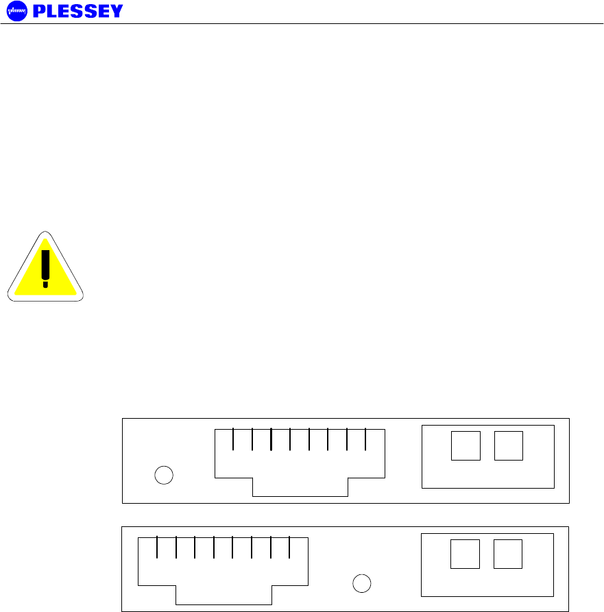
4.4 Interconnection Cable Installation
Follow these steps to install the Digital Indoor Unit to RF Unit interconnection cables.
CAUTION
- DO NOT OVER TIGHTEN THE CABLE STRAPS ON THE
CABLES AND DO NOT FASTEN THE STRAP LOCKING
MECHANISM OF THE CABLE STRAP ONTO THE CABLES.
1. On the RFU side, connect an RJ45 plug to the data cable. Place the RJ45 plug
into the RJ45 socket in the RF Unit connection box / Indoor RF Unit front panel.
2. On the RFU side, connect the DC power leads within the RF Unit Connection
Box / on the Indoor RF Unit front panel. Use the + and - connections.
18
-+
RJ45 Socket
IU/OU
LINK
18
-+
RJ45 Socket
IU/OU
LINK
Rear Panel
Front Panel
LOOKING AT THE "RF Unit" CONNECTION BOX
(Located on the rear panel of the MDR DIU, front panel of the Orion DIU)
3. If applicable: Close the RF Unit Connection Box Cover using a 2.5mm Allen key.
Make sure the rubber gaskets seal correctly over the power and data cables.
4. If applicable: Using cable ties, secure the cable to the pole at regular intervals.
5. On the DIU side, connect an RJ45 plug to the data cable. Place the RJ45 plug
into the RJ45 socket in the "RF Unit" connection box.
6. On the DIU side, connect the DC power leads to the supplied GREEN Phoenix
plug. Insert this plug into the green socket in the "RF Unit" connection box.
7. The user can see that there is a suitable DIU/RFU data interconnection if the
‘DIU/RFU Link’ LED of the DIU is lit up green.

MDR2400/5800-SR, Orion2410/5810-SRi and Orion 5825-SR
862-01881 Issue 12c Page 38
CAUTION
- UNDO THE SCREWS OF THE “CONNECTION BOX” IN A
UNIFORM MANNER. THIS ENSURES THAT THE
“CONNECTION BOX” GASKET MATERIAL RELEASES
STRESS UNIFORMLY AND DOES NOT LEAD TO THE
SECURING SCREWS BEING BENT DUE TO THE PRESSURE
PLACED ON THE CONNECTION BOX LID.
MDR2400/5800-SR, Orion2410/5810-SRi and Orion 5825-SR
862-01881 Issue 12c Page 39
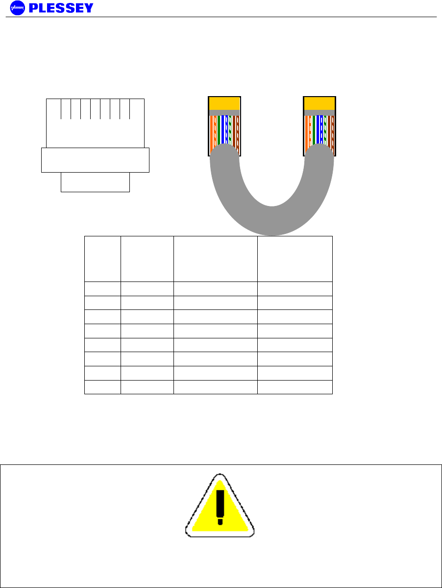
4.4.1 INTERCONNECTION CABLE WIRING DESCRIPTION
18
TOP VIEW (LOCKING
TAB UNDERNEATH)
RJ-45 PLUG
Pin DTE (on
DIGITAL
INDOOR
UNIT)
DCE (on RF
UNIT)
Wiring
1 TxD+ RxD- Orange/White
2 TxD- RxD+ White/Orange
3 RxD+ TxD+ Green/White
4† TxC+ RxC+ Blue/White
5† TxC- RxC- White/Blue
6 RxD- TxD- White/Green
7† RxC+ TxC+ Brown/White
8† RxC- TxC- White/Brown
NOTE
† VERSION 1 AND 2 RELEASES OF THE HARDWARE (INDOOR AND RF UNITS) CANNOT BE
USED INTERCHANGEABLY. FOR VERSION 2 DIU & RFU HARDWARE, USE OF TxC+, TxC-,
RxC+, RxC- FALLS AWAY AND ONLY TWO (2) TWISTED PAIRS ARE REQUIRED.

MDR2400/5800-SR, Orion2410/5810-SRi and Orion 5825-SR
862-01881 Issue 12c Page 40
5 Antenna Alignment and Software Setup
This chapter describes the procedure for software setup and antenna alignment. The
setup is done with a laptop / PC running the supplied NMS Graphical User Interface
(GUI) software. See chapter 6 for details on using the NMS / GUI.
5.1 Installation Equipment Required
The following tools and instruments are required for software setup and aligning the
antenna:
• RSSI test cable
• Voltmeter
• Wrench / spanner (see appropriate details in installation chapter depending on the
antenna being used)
• PC with NMS software and supplied serial data cable.
• Binoculars (optional) used for locating the far end site. This will assist in the
antenna alignment operation.
• GPS or Standard Compass (optional) used for locating the far end site. This will
assist in the antenna alignment operation.
• Bit Error Rate Tester and connecting leads.
5.2 Information Required
You should know:
• the proposed frequency channel plan for each station.
• the expected receive level based on the chosen system configuration and a path
loss analysis.
B.1 Antenna Alignment
5.2.1 Introduction
The RFU should be installed on both sites before alignment starts. Perform the
following steps at both stations:
1. Switch the Digital Indoor Unit power ON.
2. Install and run the NMS Software application.
3. Configure the radio channel plan as required.
4. Set the transmitted power to maximum.
5. Perform a RF loopback test at each site before starting the alignment
procedure.
5.2.2 Alignment Procedure
1. Locate the far site and point the antenna to the antenna at the far site, as
accurately as possible using binoculars or a compass.
2. Connect the multimeter to the RSSI connector on the RFU using the supplied
RSSI test cable and set the multimeter to measure volts.
3. Check the RSSI level and refer to the figure below for received power level.
4. Align the antenna until the maximum RSSI is attained.

MDR2400/5800-SR, Orion2410/5810-SRi and Orion 5825-SR
862-01881 Issue 12c Page 41
5. Secure the antenna.
6. Measure the RSSI level and record the value (see section 5.6).
7. Compare with the value with that calculated for the link i.e. using the path loss
calculation done when planning the link.
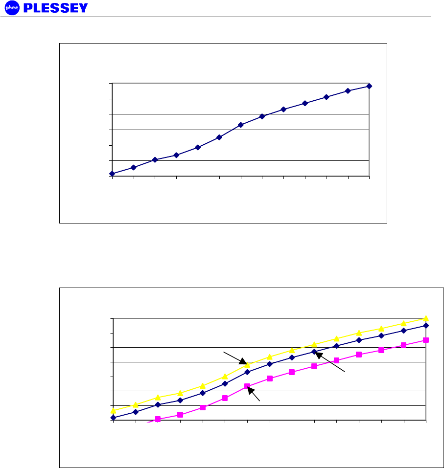
Typical Version 2 MDR OU RSSI Voltage vs Received
Signal Power (5.8GHz)
0.4
0.6
0.8
1
1.2
1.4
-80 -75 -70 -65 -60 -55 -50 -45 -40 -35 -30
Received Signal Power [dBm]
Outdoor Unit RSSI
Voltage
Figure 7. Typical Version 2 MDR5800 and Orion5810i RFU RSSI Voltage as a
function of RF input power level
-80 dBm Average 0.436 ± 0.029 V : MIB RSSI 95 ± 1 dBm (see comment below)
-30 dBm Average 1.333 ± 0.047 V : MIB RSSI 54 ± 2 dBm (see comment below)
The front panel RF Link LED, the Received Signal Strength Indicators (RSSI : on
NMS, via SNMP or as an Electrical signal on the RF Unit), Carrier-detect (NMS,
SNMP) and Frame Lock (NMS, SNMP) indicators are available to assist with link
installation and alignment.
NOTE 1 The MIB lists a value representative of the received signal level in [-dBm].
This value corresponds to the signal power measured in a 200 kHz BW centred at the
receive frequency of the radio.
When not in spectrum analyser mode, the Orion RFU translates the measured signal
power to a value corresponding to the wanted signal power in the receiver bandwidth.
NOTE 2 For the MDR and Orion10i RFUs, the RSSI values displayed in the MIB are
representative of the signal level measured over a 200kHz BW. Add ~20dB to the MIB
value for a wanted spread spectrum signal. The NMS / GUI will do this adjustment
automatically and will therefore always display the correct RSSI value.
NOTE 3 Due to the technique used to calculate the RSSI level of a wanted signal, the
measured RSSI level can differ from the actual value with up to ±3 dB.
MDR2400/5800-SR, Orion2410/5810-SRi and Orion 5825-SR
862-01881 Issue 12c Page 42
Typical MDR2400 OU RSSI Voltage vs Received
Signal Power
0.6
0.8
1
1.2
1.4
1.6
1.8
-100 -95 -90 -85 -80 -75 -70 -65 -60 -55 -50 -45 -40
Received Signal Power [dBm]
Outdoor Unit RSSI
Voltage
Figure 8. Typical MDR2400 and Orion2410i RFU RSSI Voltage as a function of RF
input power level
(See comment above.)
Typical Orion OU RSSI Voltage vs Received Signal Power
0.6
0.8
1
1.2
1.4
1.6
1.8
2
-100 -95 -90 -85 -80 -75 -70 -65 -60 -55 -50 -45 -40 -35 -30
Received Signal Power [dBm]
Outdoor Unit RSSI
Voltage
Figure 9. Typical Orion 5850 RFU RSSI Voltage as a function of RF input power level
(note the different bandwidths)
5.2.3 Set Transmitted Power Level
It is good practice to match received power levels by adjusting transmitted powers if
co-located systems are being installed. This is important to avoid interference
between co-located systems. An attenuator can be fitted between the RF Unit and the
antenna if the power level cannot be sufficiently reduced. The dBm output at the RFU
N-type connector (socket) levels are set via the NMS or using a SNMP Management
application.

MDR2400/5800-SR, Orion2410/5810-SRi and Orion 5825-SR
862-01881 Issue 12c Page 43
5.3 Software Setup
Refer to chapter 6, for setting up the following:
• Payload interface.
• Service Channel (Wayside) serial port.
• Auxiliary in/out port.
• General link parameters.
5.4 Functional Test
After completing the physical installation of the Digital Indoor Units, antennas, RF
Units and the interconnection cables, you need to commission the system. This
procedure describes how to set up the minimum requirements for successful MDR /
Orion system operation.
5.4.1 Link Bit Error Rate Performance Test
To start : when the link is setup correctly, the RF Link LEDs on both DIUs on both
sides of the RF link should be GREEN.
When the link has been setup and is running error-free:
1. Clear the Digital Indoor Unit Log using Reset Button Position ‘2’
2. Clear the Digital Indoor Unit Errors using Reset Button Position ‘1’
Perform a link bit error rate performance test as follows:
• Connect a bit error rate tester to the payload interface of the link.
• Run data over the link for a period of 24 hours.
• Record the BER.
• Record the LED statuses.
Check the Digital Indoor Unit Packet Error Results via the NMS or via SNMP access to
the Digital Indoor Unit MIB – for the NMS, right-click on the antennas in the NMS for
either side of the link and select the “Diagnostic/Error Monitor” option. Record the
results by saving the data to a file. For SNMP access, use a MIB Browser and check
the mdrmteRFLinkPerf and mdrmteG826 Performance groups.
Record all results on a test record. See MDR / Orion Test Record, section 5.6 for an
example.

MDR2400/5800-SR, Orion2410/5810-SRi and Orion 5825-SR
862-01881 Issue 12c Page 44
5.5 MDR / Orion Installation Record
Parameter Unit Site A Site B
Site Name
Antenna Type
RF cable length Meters
Lightening protection unit Yes/No
Interconnecting cable length Meters
RF Unit serial number
Digital Indoor Unit serial
number
RF Unit earthed Yes/No
Digital Indoor Unit earthed Yes/No
Power Supply Volts DC/AC
Date Name Signature
Performed by
Approved by

MDR2400/5800-SR, Orion2410/5810-SRi and Orion 5825-SR
862-01881 Issue 12c Page 45
5.6 MDR / Orion Test Record
Parameter Unit Site A Site B
Frequency channel plan:
Transmit
Receive
NOTE 1 : C is NOT used for
the MDR2400.
NOTE 2 : FCC requirements
(U.S. only), page 2.
A/B/C/D
A/B/C/D
If D – List
Transmit and
Receive
Frequencies
[MHz]
Transmitter output power
(NOTE 2)
dBm
Receiver input level (ON) Volts
Receiver input level (ON) dBm
Receiver input level (OFF) Volts
Receiver input level (OFF) dBm
Calculated input level dBm
Fade margin dB
Frame Lock indicator Colour
Fixed attenuator DB
BER-test
Hours
BER
Alarm Indicators Clear (Yes/No)
Date Name Signature
Performed by
Approved by

MDR2400/5800-SR, Orion2410/5810-SRi and Orion 5825-SR
862-01881 Issue 12c Page 46
6 NMS Software
6.1 Scope
This section provides minimal information required to install the Orion NMS. A detailed
HTML-based help document can be found on the NMS installation CD supplied with
new radios.
6.2 Introduction
The purpose of the Network Management System, hereafter called the NMS, is to
allow you to configure, manage or interrogate the following primary functional
elements of a Digital Radio Link:
• Digital Indoor Unit
• RF Unit
A Digital Radio Link consists of two Indoor-RF Unit stations connected through a radio
link.
The Orion NMS is designed to auto-detect the radio type it is connected to and can
support the following radio types:
• Orion XX
• MDR XXXX
Since the firmware and software for the MDR XXXX and the Orion XX10i RFUs are
exactly the same, the NMS has no means to detect the difference between these
units. The NMS will therefore always display the radio type as MDR XXXX.
The NMS is a PC-based software package that provides you with a graphical interface
that is used to perform on-site element management of a digital radio system. It
allows you to configure, manage and interrogate the system by selecting various
menus and options.
The hardware as well as the software constituting the NMS is collectively called the
NMS Terminal.
The NMS Terminal is the principal system support equipment associated with the radio
for system installation and commissioning.
The NMS connects to a designated NMS Terminal port (labelled Element Manager) on
the front panel of the Digital Indoor Unit, by means of a serial data interface (this cable
is supplied in the DIU box). It can also connect to any number of Digital Indoor Units
interconnected through an IP network.
The NMS communicates with SNMP agent software that is contained in each Digital
Indoor Unit. The NMS communicates with the agent’s software: the software enables
a unit to interpret MIB (Management Information Base) commands via SNMP (Simple
Network Management Protocol).

MDR2400/5800-SR, Orion2410/5810-SRi and Orion 5825-SR
862-01881 Issue 12c Page 47
NOTE The NMS application supplied with older MDR radios have been replaced with
the Java-based Orion NMS. The older NMS does not support the Orion series radios
and it is highly recommended to replace this NMS with the Orion NMS.
6.3 System requirements
The following PC system requirements apply for the Orion NMS:
• P III 450 MHz or higher CPU
• 128 MB RAM
• 20 MB Free Hard disk space
• CD-ROM Drive
• Win 98, 2000, NT or XP Operating System (Linux optional)
6.4 Installing the NMS
The NMS have been developed on the Java platform from Sun Micro Systems. This
requires the installation of a Java Runtime Environment (JRE) on the PC from where
the NMS will be used.
The installation files for the NMS and the JRE are provided on the installation CD that
is shipped with each radio.
The supplied installation files allows the NMS to be set up on any WIN32 system
(Windows 98, NT, 2000, XP). If required, a special installation can also be provided
which would allow the NMS to be installed on a system using a Linux operating
system.
6.4.1 JRE Installation
Complete the following steps to set up the required JRE on the required PC:
• Browse to the //OrionNMS/JRE folder in the root of the installation CD
• Execute the j2re-1_3_1_02-win.exe installation application
• Follow the user prompts in the JRE installation application to set up the JRE in the
preferred folder on the PC
6.4.2 NMS Installation
After installing the JRE on the PC, complete the following steps to install the NMS on
the PC:
• If a previous version of the Orion NMS have been installed on the target PC, first
uninstall the older version
• Browse to the //OrionNMS/Setup folder in the root of the installation CD
• Execute the Plessey_OrionNMS_vXpXX.exe installation application
• Follow the user prompts in the NMS installation application to set up the NMS in
the preferred folder on the PC
The NMS should now be installed on the target PC and should be available for
selection through the Start Programs menu option.

MDR2400/5800-SR, Orion2410/5810-SRi and Orion 5825-SR
862-01881 Issue 12c Page 48
6.4.3 NMS Un-Installation
Select the Uninstall menu item in the Orion NMS menu group from the Start Programs
menu to uninstall the NMS form the PC. This action removes all installed files, menu
items and register entries from the PC.
6.5 Help documentation
The HTML based help documents for the Orion NMS application is available on the
installation CD at the following path: //OrionNMS/help/Orion NMS Help.htm. The
help document can be accessed by opening it with an Internet browser of your choice.
The help documents can also be opened from the Windows Start Menu folder created
for the Orion NMS or through the Help|Contents menu in the Orion NMS application.

MDR2400/5800-SR, Orion2410/5810-SRi and Orion 5825-SR
862-01881 Issue 12c Page 49
7 Maintenance Information
1. The user is advised to refer to the Technical Data section (paragraph 8.5.10) for
details on DIU/RFU interconnection cables (customer-furnished).
2. The “Ordering Information” paragraph in the Technical Data section (paragraph
8.6) provides details on part numbers for items that can be ordered.
3. Paragraph 4 of this manual lists customer furnished equipment that should be
used for installing the MDR / Orion product.
4. There are two options to control the MDR / Orion products via SNMP.
a. One uses any open-standard-compliant SNMP Management package (HP
OpenView, SNMPc etc): in this case, one has access to the full compliment of
the product's MIB elements.
b. The NMS application package supplied with the product accesses a subset of
the MIB. It has a graphical user interface carefully designed to assist
installation and maintenance staff.

MDR2400/5800-SR, Orion2410/5810-SRi and Orion 5825-SR
862-01881 Issue 12c Page 50
8 Technical Data
8.1 Environmental Requirements
8.1.1 Outdoor Equipment
This specification applies to the outdoor type RFUs only.
Operating temperature: -30°C to +60°C
Relative humidity: 8-100%
Atmospheric pressure: 0.7 to 1.06 kPa
Lightning protection ITU-T K.20
8.1.2 Indoor Equipment
This specification applies to all indoor mounted units.
Operating temperature: 0°C to +50°C
Relative humidity: 5-90%
Lightning protection: ITU-T K.20
8.2 Mechanical Information for Outdoor Equipment
Dimensions (HxWxD): 335mm x 231mm x 124mm
Weight: ~ 5.9 Kg
8.3 Mechanical Information for Indoor Equipment
Dimensions (HxWxD): 45mm x 480 mm x 265mm
Mounting: 19” Rack, 1U high or Table top
Weight: ~ 2.9 Kg
8.4 Power Supply Requirements
DC power supply: 21 to 56 VDC (58 VDC when indicated as such)
DC power supply grounding: Positively or negatively grounded
Power consumption
(MDR2400/5800/
Orion2410i/Orion5810i)
35 W typical, 45 W maximum.
Power consumption
(Orion 5825):
35 W typical, 45 W maximum – standard power
42 W typical, 52 W maximum – high power

MDR2400/5800-SR, Orion2410/5810-SRi and Orion 5825-SR
862-01881 Issue 12c Page 51
8.5 Electrical Performance
8.5.1 General Characteristics
MDR2400-SR and Orion2410-SRi
Frequency Range: 2400 to 2483.5 MHz
Payload Data Capacity: T1 (1.544 Mbps/s) / E1 (2.048 Mbps)
2T1 / 2E1
4T1 / 4E1
RF Channel Bandwidth: 17 MHz
Go/Return spacing: Can be adjusted as fixed go-return spacing.
NOT mandatory in the ISM licence-free bands.
Modulation: CCK
Processing Gain: 11 dB
Frequency Channel Plan A: 2410 and 2460 MHz
Frequency Channel Plan B: 2426 and 2476 MHz
Transmission Delay: 600 us maximum for radios only (one-way)
MDR5800-SR and Orion5810-SRi
Frequency Range: 5731 to 5844 MHz
Payload Data Capacity: T1 (1.544 Mbps/s) / E1 (2.048 Mbps)
2T1 / 2E1
4T1 / 4E1
RF Channel Bandwidth: 17 MHz
Go/Return spacing: Can be adjusted as fixed go-return spacing.
NOT mandatory in the ISM licence-free bands.
Modulation: CCK
Processing Gain: 11 dB
Frequency Channel Plan A: 5735 and 5804 MHz
Frequency Channel Plan B: 5753 and 5822 MHz
Frequency Channel Plan C: 5771 and 5840 MHz
Transmission Delay: 600 us maximum for radios only (one-way)

MDR2400/5800-SR, Orion2410/5810-SRi and Orion 5825-SR
862-01881 Issue 12c Page 52
Orion 5825-SR
Frequency Range: 5731 to 5844 MHz
Payload Data Capacity: • 1 - 4T1 (1.544 Mbps/s) /
1 - 4E1 (2.048 Mbps) (2.6MHz BW)
• 1 - 8T1 (1.544 Mbps/s) /
1 - 8E1 (2.048 Mbps) (5.4MHz, 8.0MHz
BW)
RF Channel Bandwidth:
(Selectable)
2.6MHz
5.4MHz
8.0MHz
Go/Return spacing: Can be adjusted as fixed go-return spacing.
NOT mandatory in the ISM licence-free bands.
Modulation: 16-QAM
Frequency Channel Plan A: 5731 and 5801 MHz (2.6MHz BW)
5732 and 5802 MHz (5.4MHz BW)
5734 and 5804 MHz (8.0MHz BW)
Frequency Channel Plan B: 5752 and 5822 MHz (all bandwidths)
Frequency Channel Plan C: 5774 and 5844 MHz (2.6MHz BW)
5773 and 5843 MHz (5.4MHz BW)
5771 and 5841 MHz (8.0MHz BW)
Transmission Delay: 600 us maximum for radios only (one-way)

MDR2400/5800-SR, Orion2410/5810-SRi and Orion 5825-SR
862-01881 Issue 12c Page 53
8.5.2 Transceiver Characteristics
8.5.2.1 Frequency Band: MDR2400 and Orion2410i Lowband RF Units
Transmit band: 2410 – 2426 MHz (Centre frequency)
Receive band: 2458 – 2474 MHz (Centre frequency)
8.5.2.2 Frequency Band: MDR2400 and Orion2410i Highband RF Units
Transmit band: 2458 – 2474 MHz (Centre frequency)
Receive band: 2410 – 2426 MHz (Centre frequency)
8.5.2.3 Frequency Band: MDR5800 and Orion5810i Lowband RF Units
Transmit band: 5725 – 5787 MHz (Band edge)
Receive band: 5787 – 5850 MHz (Band edge)
8.5.2.4 Frequency Band: MDR5800 and Orion5810i Highband RF Units
Transmit band: 5787 – 5850 MHz (Band edge)
Receive band: 5725 – 5787 MHz (Band edge)
8.5.2.5 Frequency Band: Orion 5850 Lowband RF Units
Transmit band: 5731 – 5774 MHz (Center frequency)
Receive band: 5801 – 5844 MHz (Center frequency)
8.5.2.6 Frequency Band: Orion 5850 Highband RF Units
Transmit band: 5801 – 5844 MHz (Center frequency)
Receive band: 5731 – 5774 MHz (Center frequency)

MDR2400/5800-SR, Orion2410/5810-SRi and Orion 5825-SR
862-01881 Issue 12c Page 54
8.5.3 RF Interface
Transmitted Power +2 to+24 dBm – MDR2400, MDR5800, Orion2410i
+2 to+25 dBm – Orion5810i
+2 to +24 dBm – Orion 5850 high output power,
software adjustable (incl. mute)
Receiver Sensitivity: Up to 4T1/4E1 :
-88dBm for BER = 10-6 (MDR2400)
-86dBm for BER = 10-6 (MDR5800)
Up to 8T1/E1 : Orion 5850, 16 QAM
-88dBm for BER = 10-6 (2.6 MHz BW)
-85dBm for BER = 10-6 (5.4 MHz BW)
-83dBm for BER = 10-6 (8 MHz BW)
Maximum Receive Level: -30dBm
8.5.4 Payload Data Interfaces
8.5.4.1 1, 2, 4 or 8 (i.e. nE1) Interface
Data Rate: Full duplex E1 (2.048Mbit/s), 2E1, 4E1 or 8E1
Digital Interface: ITU-T G.703
Connectors: Balanced 110 ohm on DB25
Balanced 110 ohm on RJ45 (Orion DIU only)
Unbalanced 75 ohm on BNC’s
(Available on one of the MDR DIU variants)
Line code: HDB3 or AMI selectable, refer to Section 2.3.1
Jitter and Wander: ITU-T G.823
8.5.4.2 1, 2, 4 or 8 (i.e. nT1) Interface
Data Rate: Full duplex T1 (1.544Mbit/s), 2T1, 4T1 or 8T1
Digital Interface: DSX-1, G.703 compliant
Connectors: Balanced 110 ohm on DB25
Balanced 110 ohm on RJ45 (Orion DIU only)
Unbalanced 75 ohm on BNC’s
(Available on one of the MDR DIU variants)
Line code: AMI or B8ZS selectable, refer to Section 2.3.1
Jitter and Wander: ITU-T G.823

MDR2400/5800-SR, Orion2410/5810-SRi and Orion 5825-SR
862-01881 Issue 12c Page 55
8.5.5 Ethernet Traffic Interface
Data Rate: < 8 Mbps Half / full duplex software selectable
(Refer to Chapter G, page 114)
Digital Interface: 10 BaseT, Half / full duplex, DTE
Connector: RJ45
8.5.6 Auxiliary Input Interface (CONTACT CLOSURE)
Number of Inputs: 2
Maximum voltage: 12V
Logical zero: Short from input to return pin
Logical one: Open input to return pin
8.5.7 Auxiliary Output Interface
Number of outputs: 2
States: Normally-open and normally-closed
Contact rating: DC: 220 V, 1 A, 60 W
AC: 250 V, 1 A, 125 VA
8.5.8 Wayside channel interface
Interface standard: RS232, DCE
Handshaking: None, Hardware
Port rate: 115,200 bps
8.5.9 Element Manager Port Interface
Interface standard: RS232, DTE
Handshaking: Hardware
Data rate: 115,200 bps
8.5.10 Indoor/RF Unit Interface
The physical interface between the Indoor and RF Unit is IEEE802.3 Ethernet. As
such, the same considerations that apply between standard routers/switches/hubs and
PC LAN cards should be adhered to when selecting lengths of cables between the
RFU and the DIU. Cable lengths of up to 120 meters have been tested in a laboratory
environment.

MDR2400/5800-SR, Orion2410/5810-SRi and Orion 5825-SR
862-01881 Issue 12c Page 56
The following table lists information to assist the user to select cables to be used
between the Indoor and RF Units.
Interconnecting cable
Data
South Africa
STP (FTP) 4 Pairs Solid Cat 5, PVC FR UV protected Polifin
H2/J263/904 Outer Black. Outer diameter of cable : 7.3mm ± 0.5mm.
(this is an “upjacketed” STP 4 Pair cable).
This is a standard FTP
Cat 5 cable that is
‘upjacketed’ with suitable
plastic for FR/UV (Flame
retardant/Ultra Violet)
protection.
Other cables:
1. Superior Essex BBDN CAT 5 cable P/N 04-0010-34 (7.8mm)
2. Superior Essex CAT 5 P/N 18-241-31 18-241-11 (5.1mm)
3. General Cable CAT 5 P/N 2137113 2137114 (5.6mm)
4. Belden CAT 5 P/N BC1002 (6.0mm)
Option 1 is the preferred choice. For the cables that have diameters
less the required OD, one can use one or two pieces of heatshrink on
the cable where it passes through the gasket.
Interconnecting cable
Power
South Africa
Power 1.5mm sq stranded PVC Insulated, PVC FR UV protected Polifin
H2/J263/904 Outer Black 300/500V Temp -20°C to +85°C. Cable outer
diameter: between 7.4mm and 9mm i.e. 8.2mm ± 0.8mm.
Other cables:
Superior Essex type SJOOW flexible cable P/N 441821* (7.4mm)
Carol Cable (General Cable) SJOW/SJO P/N 02001 18 gauge 2
conductor (7.8mm)

MDR2400/5800-SR, Orion2410/5810-SRi and Orion 5825-SR
862-01881 Issue 12c Page 57
8.6 Ordering Information
To confirm the correct order numbers, please visit www.plesseybbw.com/download.htm to download an "Order Number
Generator" utility.
Part No Model Number Description
651-03994-01-H1 or
651-03994-01-L1 MDR2400-ET1
MDR2400 Radio: Digital Indoor Unit (DB25 balanced
payload) and High or Low Band RF Unit, Type-N RF
output, high power output, Full T1/E1, 2Mbps or
1.5Mbps data interface
651-04106-01-H1 or
651-04106-01-L1
As above with 75 Ohm, BNC unbalanced payload
also available.
651-03994-01-H2 or
651-03994-01-L2 MDR2400-ET2
MDR2400 Radio: Digital Indoor Unit (DB25 balanced
payload) and High or Low band RF Unit, Type-N RF
output, high power output, Full 2xT1/2xE1, 2x2Mbps
or 2x1.5Mbps data interface
651-04106-01-H2 or
651-04106-01-L2
As above with 75 Ohm, BNC unbalanced payload
also available.
651-03994-01-H4 or
651-03994-01-L4 MDR2400-ET4
MDR2400 Radio: Digital Indoor Unit (DB25 balanced
payload) and High or Low band RF Unit, Type-N RF
output, high power output, Full 4xT1/4xE1, 4x2Mbps
or 4x1.5Mbps data interface
651-04106-01-H4 or
651-04106-01-L4
As above with 75 Ohm, BNC unbalanced payload
also available.
The MDR2400 operates from 21-56VDC (58VDC if indicated as such), optional 110-220VAC power
supply available below.
A complete link requires two radios, one must be High Band (HB) and the other a Low Band (LB).
Part No Model Number Description
651-04318-02-H1 or
651-04318-02-L1 Orion5810-SRi
ET1
Orion5810-SRi Radio: Digital Indoor Unit (DB25
balanced payload) and High or Low band RF Unit,
Type-N RF output, high power output, Full
1xT1/4xE1, 1x2Mbps or 1x1.5Mbps data interface
651-04318-02-H2 or
651-04318-02-L2 Orion5810-SRi
ET2
Orion5810-SRi Radio: Digital Indoor Unit (DB25
balanced payload) and High or Low band RF Unit,
Type-N RF output, high power output, Full
2xT1/4xE1, 2x2Mbps or 2x1.5Mbps data interface
651-04318-02-H4 or
651-04318-02-L4 Orion5810-SRi
ET4
Orion5810-SRi Radio: Digital Indoor Unit (DB25
balanced payload) and High or Low band RF Unit,
Type-N RF output, high power output, Full
4xT1/4xE1, 4x2Mbps or 4x1.5Mbps data interface
The Orion5810-SRi operates from 21-56VDC (58VDC if indicated as such), optional 110-220VAC
power supply available below.
A complete link requires two radios, one must be High Band (HB) and the other a Low Band (LB).
Part No Model Number Description
651-04317-01-H1 or
651-04317-01-L1 Orion2410-SRi
ET1
Orion2410-SRi Radio: Digital Indoor Unit (DB25
balanced payload) and High or Low band RF Unit,
Type-N RF output, high power output, Full
1xT1/4xE1, 1x2Mbps or 1x1.5Mbps data interface

MDR2400/5800-SR, Orion2410/5810-SRi and Orion 5825-SR
862-01881 Issue 12c Page 58
651-04317-01-H2 or
651-04317-01-L2 Orion2410-SRi
ET2
Orion2410-SRi Radio: Digital Indoor Unit (DB25
balanced payload) and High or Low band RF Unit,
Type-N RF output, high power output, Full
2xT1/4xE1, 2x2Mbps or 2x1.5Mbps data interface
651-04317-01-H4 or
651-04317-01-L4 Orion2410-SRi
ET4
Orion2410-SRi Radio: Digital Indoor Unit (DB25
balanced payload) and High or Low band RF Unit,
Type-N RF output, high power output, Full
4xT1/4xE1, 4x2Mbps or 4x1.5Mbps data interface
The Orion2410-SRi operates from 21-56VDC (58VDC if indicated as such), optional 110-220VAC
power supply available below.
A complete link requires two radios, one must be High Band (HB) and the other a Low Band (LB).
Part No Model Number Description
651-04253-01-H08
or
651-04253-01-L08
Orion5825-ET8
High Power (24 dBM) Orion5825 Radio: Digital
Indoor Unit and High or Low Band RF Unit, Type-N
RF output, Full 8xT1/8xE1, 8x2Mbps or 8x1.5Mbps
data interface
The Orion 5825 operates from 21-56VDC (58VDC if indicated as such), optional 110-220VAC
power supply available below.
A complete link requires two radios, one must be High Band (HB) and the other a Low Band (LB).
Accessories & Upgrades
Part Number Description
651-04226 MDR2400SR, MDR5800SR, Orion2410SRi and Orion5810SRi
1+1 hot standby combiner/splitter (4-tribs)
651-04227 ORION 5825 1+1 hot standby combiner/splitter (8-tribs)
651-03864 Bench Power Supply 110-220VAC to 24VDC
651-07865 19" Rack Mount for Outdoor RF Unit (4u high)
651-03865 MDR Digital Indoor Unit Upgrade 1xT1/E1 to 2xT1/E1
651-03866 MDR Digital Indoor Unit Upgrade 2xT1/E1 to 4xT1/E1
651-03867 MDR Digital Indoor Unit Upgrade 1xT1/E1 to 4xT1/E1
651-04251 MDR / Orion NMS Software CD - Spare Part
651-03809 RFU Pole Mounting Kit - Spare Part
862-01881 MDR / Orion Digital Radio System User Manual - Spare Part
660-03405 MDR / Orion Cable Assembly: RSSI Test Loom - Spare Part
660-03770 Digital Indoor Unit to Indoor RF Unit power and data cable –
Spare Part

MDR2400/5800-SR, Orion2410/5810-SRi and Orion 5825-SR
862-01881 Issue 12c Page 59
The MDR and Orion systems use standard CAT5 Ethernet cable and RJ-45 connectors for
connecting the Digital Indoor Unit to the RF Unit. A two-wire power cable is also required between
the Digital Indoor Unit and the RF Unit.
NOTE Screened CAT-5 cable (for noise immunity) and UV resistant cables (for long-
term outdoor use) are required to meet FCC EMC emission standards for this type of
product.

MDR2400/5800-SR, Orion2410/5810-SRi and Orion 5825-SR
862-01881 Issue 12c Page 60
Spare Parts for MDR2400, MDR5800, Orion2410i, Orion5810i and Orion 5825
radios
Part Number Description
651-04104-02-1 MDR MTE Digital Indoor Unit 1xT1/E1 - Spare Part
651-04104-02-2 MDR MTE Digital Indoor Unit 2xT1/E1 - Spare Part
651-04104-02-4 MDR MTE Digital Indoor Unit 4xT1/E1 - Spare Part
651-04105-02-1 MDR MTE 75/120 OHM Digital Indoor Unit (BNC) 1xT1/E1 -
Spare Part
651-04105-02-2 MDR MTE 75/120 OHM Digital Indoor Unit (BNC) 2xT1/E1 -
Spare Part
651-04105-02-4 MDR MTE 75/120 OHM Digital Indoor Unit (BNC) 4xT1/E1 -
Spare Part
651-04316-01-1 Orion 10 Digital Indoor Unit 1xT1/E1
651-04316-01-2 Orion 10 Digital Indoor Unit 2xT1/E1
651-04316-01-4 Orion 10 Digital Indoor Unit 4xT1/E1
651-04231-01-08 Orion 25 Digital Indoor Unit 8xT1/E1
651-03806-02L MDR5800 Low Band Outdoor RF Unit - Spare Part
651-03806-02H MDR5800 High Band Outdoor RF Unit - Spare Part
651-03905-01L MDR2400 Low Band Outdoor RF Unit - Spare Part
651-03905-01H MDR2400 High Band Outdoor RF Unit - Spare Part
651-04299-02.1L Orion5810i Low Band Indoor RF Unit - Spare Part
651-04299-02.1H Orion5810i High Band Indoor RF Unit - Spare Part
651-04307-01.1L Orion2410i Low Band Indoor RF Unit - Spare Part
651-04307-01.1H Orion2410i High Band Indoor RF Unit - Spare Part
651-04255-01L Orion 5850 Low Band RF Unit - Spare Part
651-04255-01H Orion 5850 High Band RF Unit - Spare Part

MDR2400/5800-SR, Orion2410/5810-SRi and Orion 5825-SR
862-01881 Issue 12c Page 61
MDR2400 Ordering Information:
Part no’s:
1T1/E1 Radio: 651-03994-01-H1 or 651-03994-01-L1
2T1/E1 Radio: 651-03994-01-H2 or 651-03994-01-L2
4T1/E1 Radio: 651-03994-01-H4 or 651-03994-01-L4
Each MDR2400 radio includes the following:
Part No Description QTY
651-04104-02-1 or
651-04104-02-2 or
651-04104-02-4
MDR Digital Indoor Unit: 1xT1/E1or 2xT1/E1 or 4xT1/E1, 120
Ohm
1
651-03905-01H or
651-03905-01L MDR2400 ET4 RF Unit 1
651-03809 MDR 5800 RFU Pole Mounting Kit 1
862-01881 MDR / Orion Digital Radio System User Manual 1
651-04252 NMS Software CD 1
660-03405 RSSI Cable 1
It is possible to purchase upgrades for T1/E1 Digital Indoor Units (upgrades to 2T1/E1
or 4T1/E1). The user contacts the factory or distributor and provides the Digital
Indoor Unit Bar Code number details. The factory then supplies a “Tributary Code”,
unique to the Digital Indoor Unit, which is entered using the MIB (MDR v.1 & 2+ and
Orion products) or using the NMS (v. 2+ and Orion products).

MDR2400/5800-SR, Orion2410/5810-SRi and Orion 5825-SR
862-01881 Issue 12c Page 62
MDR5800 Ordering Information:
Part no’s:
1T1/E1 Radio: 651-03853-02-H1 or 651-03853-02-L1
2T1/E1 Radio: 651-03853-02-H2 or 651-03853-02-L2
4T1/E1 Radio: 651-03853-02-H4 or 651-03853-02-L4
Each MDR5800 radio includes the following:
Part No Description QTY
651-04104-02-1 or
651-04104-02-2 or
651-04104-02-4
MDR Digital Indoor Unit: 1xT1/E1or 2xT1/E1 or 4xT1/E1, 120
Ohm
1
651-03806-02H or
651-03806-02L MDR5800 RF Unit 1
651-03809 MDR 5800 RFU Pole Mounting Kit 1
862-01881 MDR / Orion Digital Radio System User Manual 1
651-04252 NMS Software CD 1
660-03405 RSSI Cable 1
It is possible to purchase upgrades for T1/E1 Digital Indoor Units (upgrades to 2T1/E1
or 4T1/E1). The user contacts the factory or distributor and provides the Digital
Indoor Unit Bar Code number details. The factory then supplies a “Tributary Code”,
unique to the Digital Indoor Unit, which is entered using the MIB (MDR v.1 & 2+ and
Orion products) or using the NMS (v. 2+ and Orion products).

MDR2400/5800-SR, Orion2410/5810-SRi and Orion 5825-SR
862-01881 Issue 12c Page 63
ORION5810-SRi Ordering Information:
Part no’s:
1T1/E1 Radio: 651-04318-02-H1 or 651-04318-02-L1
2T1/E1 Radio: 651-04318-02-H2 or 651-04318-02-L2
4T1/E1 Radio: 651-04318-02-H4 or 651-04318-02-L4
Each Orion5810-SRi radio includes the following:
Part No Description QTY
651-04104-02-1 or
651-04104-02-2 or
651-04104-02-4
MDR Digital Indoor Unit: 1xT1/E1or 2xT1/E1 or 4xT1/E1, 120
Ohm
1
651-04299-02H or
651-04299-02L Orion5810i Indoor RF Unit 1
862-01881 MDR / Orion Digital Radio System User Manual 1
651-04252 NMS Software CD 1
660-03405 RSSI Cable 1
660-03770 Digital Indoor Unit to Indoor RF Unit power and data cable 1
It is possible to purchase upgrades for T1/E1 Digital Indoor Units (upgrades to 2T1/E1 or 4T1/E1).
The user contacts the factory or distributor and provides the Digital Indoor Unit Bar Code number
details. The factory then supplies a “Tributary Code”, unique to the Digital Indoor Unit, which is
entered using the MIB (MDR v.1 & 2+ and Orion products) or using the NMS (v. 2+ and Orion
products).

MDR2400/5800-SR, Orion2410/5810-SRi and Orion 5825-SR
862-01881 Issue 12c Page 64
ORION2410-SRi Ordering Information:
Part no’s:
1T1/E1 Radio: 651-04317-01-H1 or 651-04317-01-L1
2T1/E1 Radio: 651-04317-01-H2 or 651-04317-01-L2
4T1/E1 Radio: 651-04317-01-H4 or 651-04317-01-L4
Each Orion2410-SRi radio includes the following:
Part No Description QTY
651-04104-02-1 or
651-04104-02-2 or
651-04104-02-4
MDR Digital Indoor Unit: 1xT1/E1or 2xT1/E1 or 4xT1/E1, 120
Ohm
1
651-04307-01H or
651-04307-01L Orion2410i Indoor RF Unit 1
862-01881 MDR / Orion Digital Radio System User Manual 1
651-04252 NMS Software CD 1
660-03405 RSSI Cable 1
660-03770 Digital Indoor Unit to Indoor RF Unit power and data cable 1
It is possible to purchase upgrades for T1/E1 Digital Indoor Units (upgrades to 2T1/E1 or 4T1/E1).
The user contacts the factory or distributor and provides the Digital Indoor Unit Bar Code number
details. The factory then supplies a “Tributary Code”, unique to the Digital Indoor Unit, which is
entered using the MIB (MDR v.1 & 2+ and Orion products) or using the NMS (v. 2+ and Orion
products).

MDR2400/5800-SR, Orion2410/5810-SRi and Orion 5825-SR
862-01881 Issue 12c Page 65
Orion 5825-SR Ordering Information:
Part no’s:
8T1/E1 Radio: 651-04253-01-H08 or 651-04253-01-L08
Each Orion 5825 radio includes the following:
Part No Description QTY
651-04231-01-08 Orion 25 Digital Indoor Unit: 8xT1/E1 1
651-04255-01H or
651-04255-01L Orion 5850 RF Unit 1
651-03809 MDR / Orion RFU Pole Mounting Kit 1
862-01881 MDR / Orion Digital Radio System User Manual 1
651-04252 NMS Software CD 1
660-03405 RSSI Cable 1
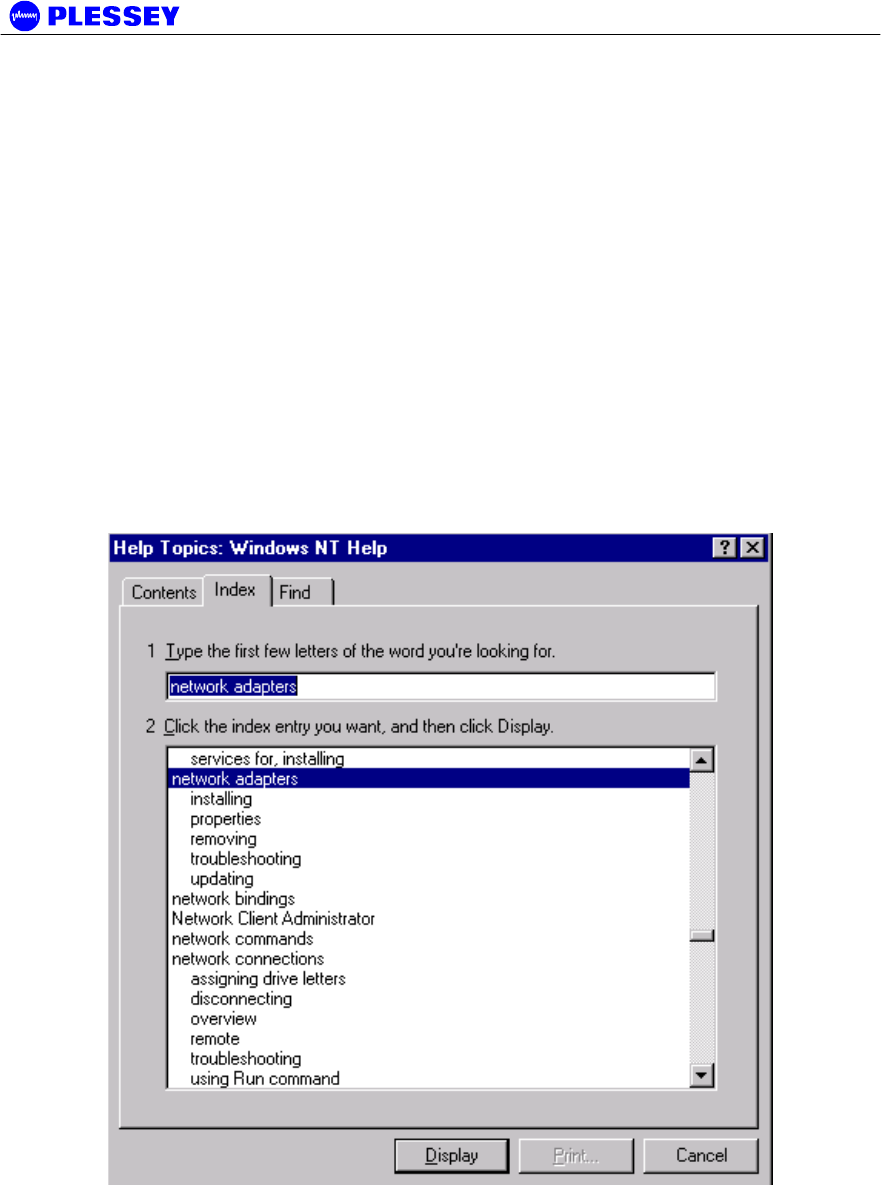
MDR2400/5800-SR, Orion2410/5810-SRi and Orion 5825-SR
862-01881 Issue 12c Page 66
A Appendix: Element Manager Port Point-to-Point Serial
Communications Setup
This appendix summarises how to set up a network connection (using PPP) between
a computer and the MDR / Orion DIU’s Element Manager port. It lists how the
connection can be setup and configured to allow data transfer and SNMP-based
control of the MDR / Orion DIU.
Note : For both NT and Win 95 or 98 machines, check
that a Network Adapter is installed.
The following screen capture shows the Windows help available to assist setting up a
serial comms network adapter.
A.1 Adding a Modem : Windows NT
1. When working with a PC running a Windows NT, add a modem using the following
screen as a guideline.

MDR2400/5800-SR, Orion2410/5810-SRi and Orion 5825-SR
862-01881 Issue 12c Page 67
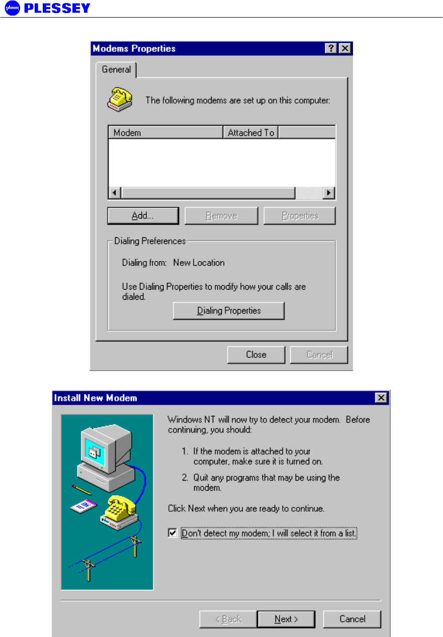
MDR2400/5800-SR, Orion2410/5810-SRi and Orion 5825-SR
862-01881 Issue 12c Page 68
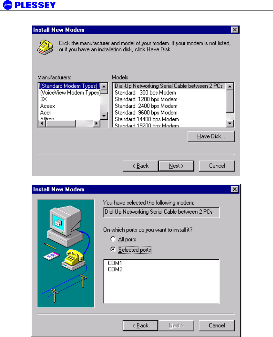
MDR2400/5800-SR, Orion2410/5810-SRi and Orion 5825-SR
862-01881 Issue 12c Page 69
2. Select the COM port to use – push the Next when the COM port has been
selected.
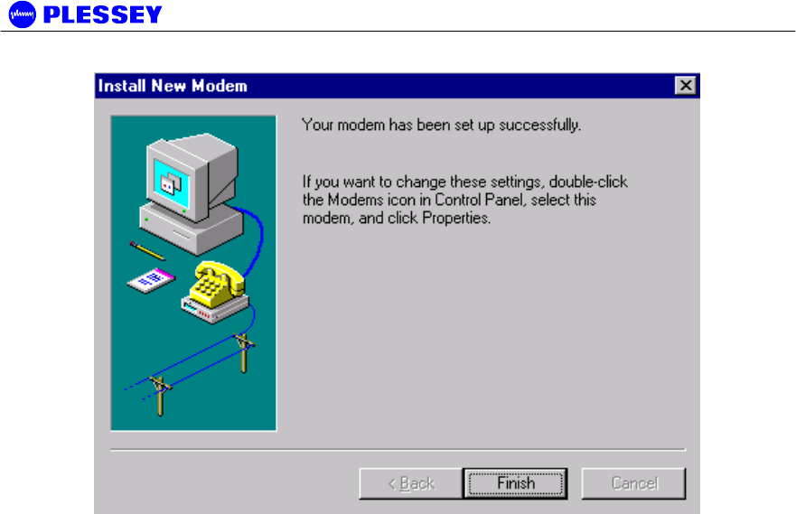
MDR2400/5800-SR, Orion2410/5810-SRi and Orion 5825-SR
862-01881 Issue 12c Page 70
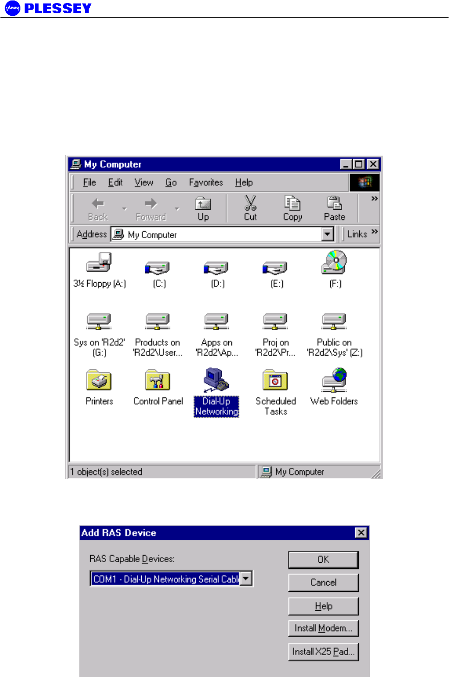
MDR2400/5800-SR, Orion2410/5810-SRi and Orion 5825-SR
862-01881 Issue 12c Page 71
A.2 Adding Dial-up Networking : Windows NT
A.2.1 To add dial-up networking
1. From the desktop, open the My Computer icon and double-click the Dial-up
Networking icon.
2. The following windows are displayed:
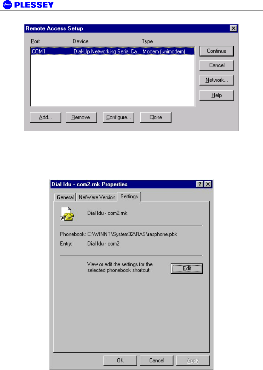
MDR2400/5800-SR, Orion2410/5810-SRi and Orion 5825-SR
862-01881 Issue 12c Page 72
3. Whether COM1 or COM2 is selected, setup the connection using the following screens as
a guideline. This allows establishment of a PPP connection between the computer and the
DIU’s Element Manager port.
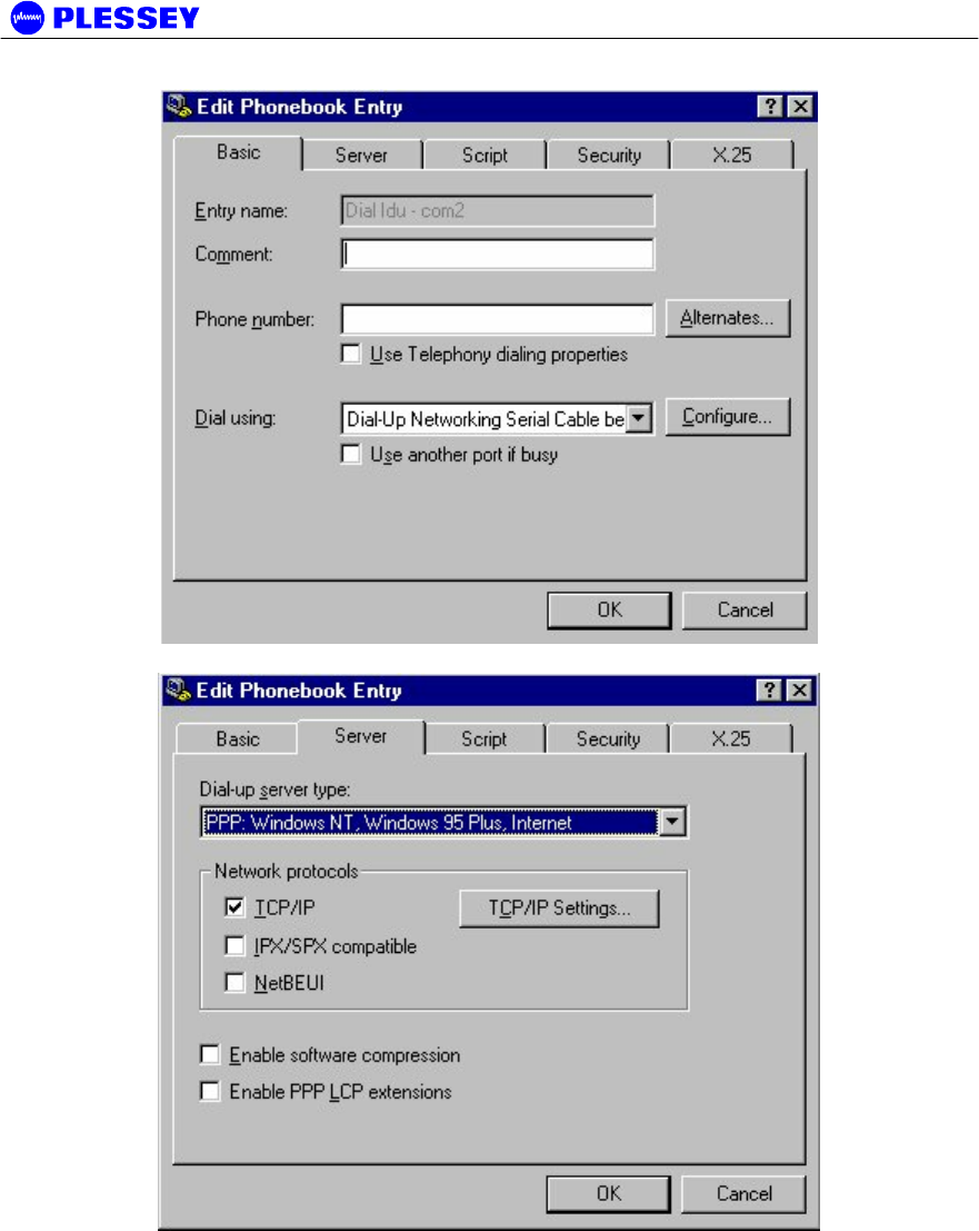
MDR2400/5800-SR, Orion2410/5810-SRi and Orion 5825-SR
862-01881 Issue 12c Page 73
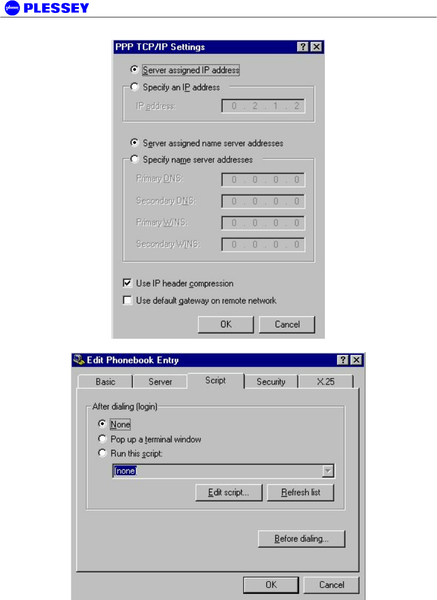
MDR2400/5800-SR, Orion2410/5810-SRi and Orion 5825-SR
862-01881 Issue 12c Page 74
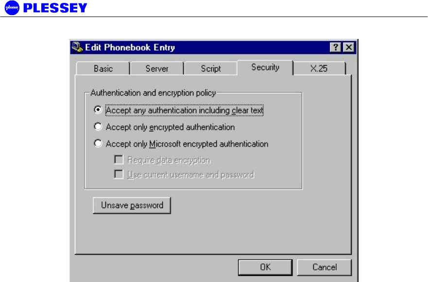
MDR2400/5800-SR, Orion2410/5810-SRi and Orion 5825-SR
862-01881 Issue 12c Page 75

MDR2400/5800-SR, Orion2410/5810-SRi and Orion 5825-SR
862-01881 Issue 12c Page 76
A.3 Adding a Modem : Windows 95/98
1. When working with a PC running a Windows 95/98, add a modem using the
following screen as a guideline.
3. Use the mdrnull.inf to add a serial cable modem connection capability to the PC or laptop.