Aviat Networks 3ECJ68B3E PTP Radio User Manual 862 01881 12c
Aviat Networks PTP Radio 862 01881 12c
Contents
- 1. Manual 1 revised
- 2. Manual 2 revised
Manual 2 revised
MDR2400/5800-SR, Orion2410/5810-SRi and Orion 5825-SR
862-01881 Issue 12c Page 77
4. Once setup, use the following screens to set up the COM port’s parameters.
MDR2400/5800-SR, Orion2410/5810-SRi and Orion 5825-SR
862-01881 Issue 12c Page 78
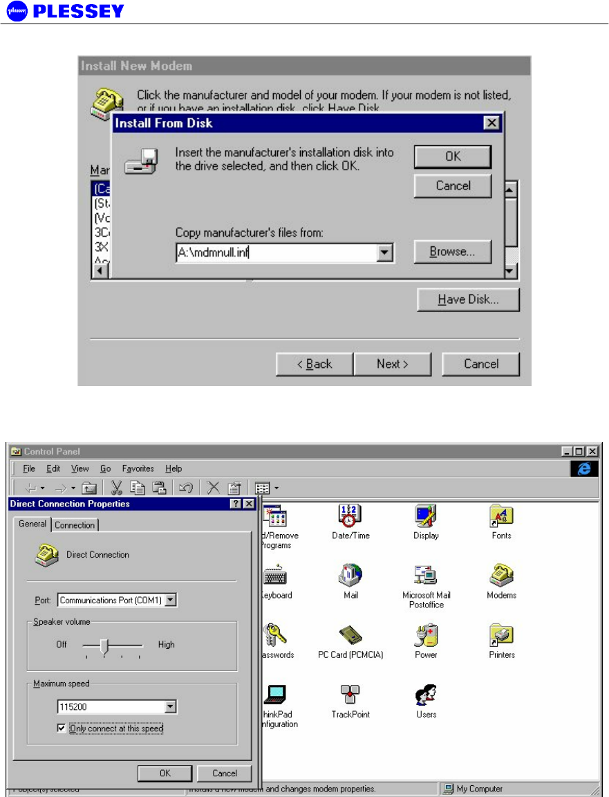
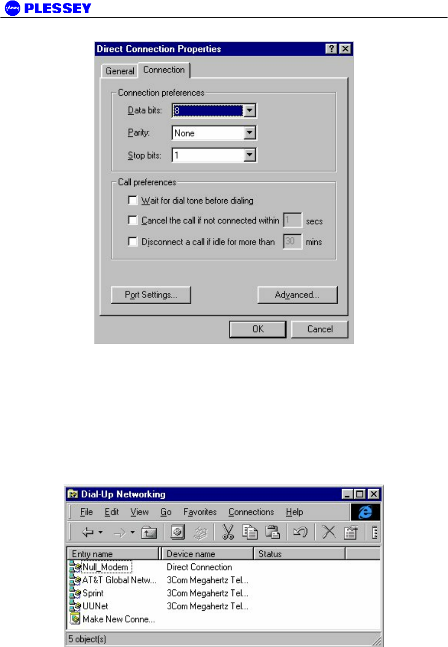
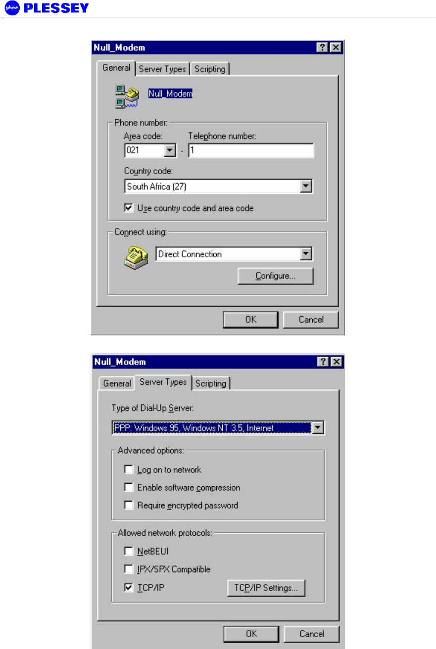
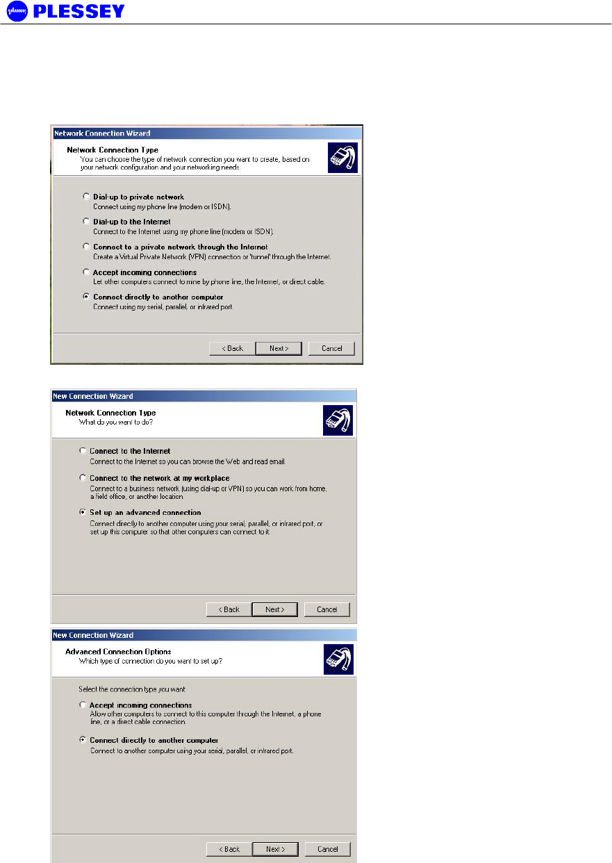
A.4 Adding Dial-up Networking : Windows 95/98
1. After adding the modem, set up the connection properties using the following screens as a
guideline. This will allow establishment of a PPP connection between the computer and
the DIU’s Element Manager port. A Null_Modem connection option as shown below will be
created. If one doesn’t exist, double click on the “Make New Connection” icon.
MDR2400/5800-SR, Orion2410/5810-SRi and Orion 5825-SR
862-01881 Issue 12c Page 79
MDR2400/5800-SR, Orion2410/5810-SRi and Orion 5825-SR
862-01881 Issue 12c Page 80
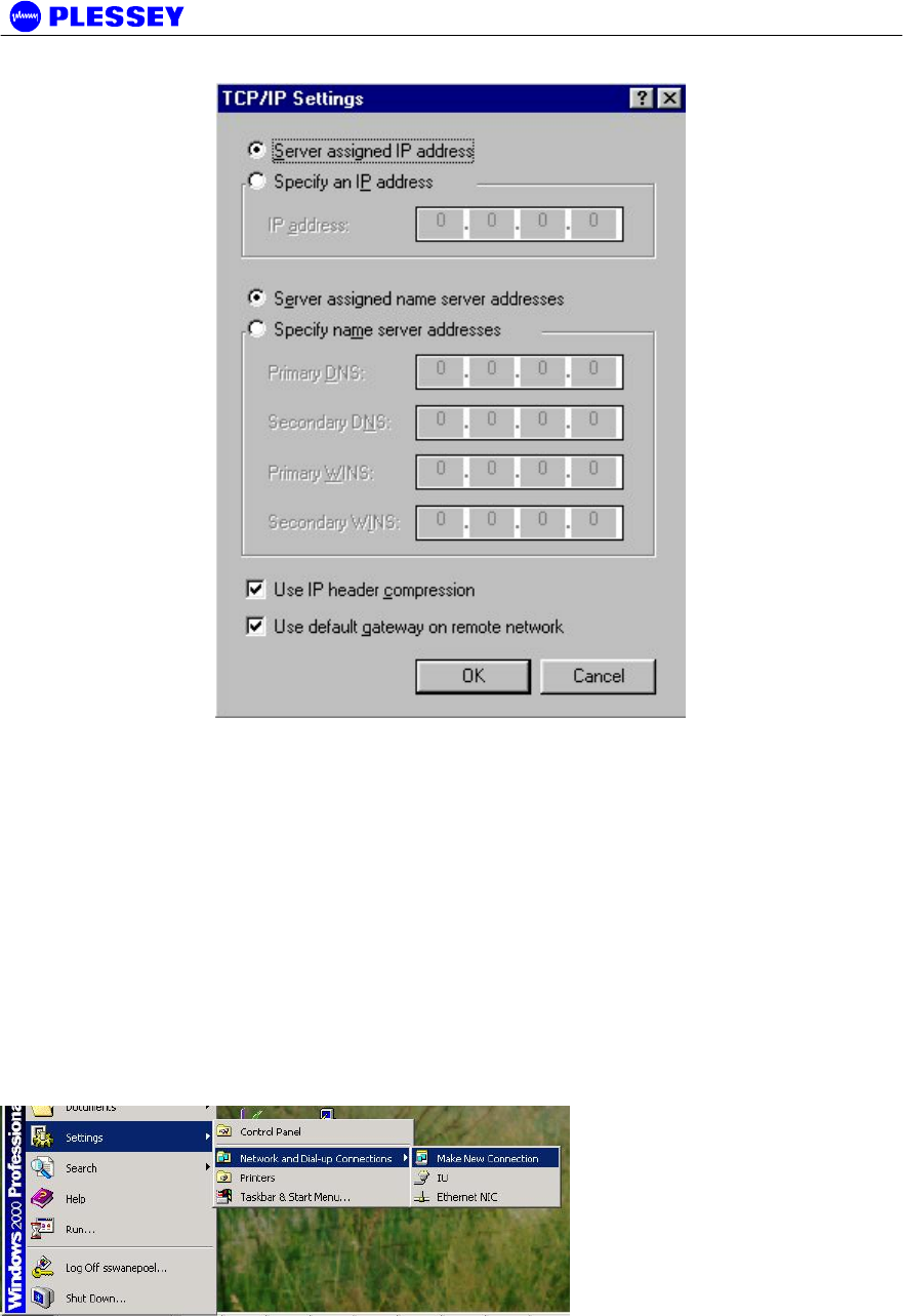
A.5 Adding Dial-up Networking : Windows 2000 / Windows XP
A.5.1 To add dial-up networking
The installation procedure documented here is based on the procedure that should
be followed for Windows 2000. Some of the configuration windows for Windows
XP may look slightly different, and may appear in a different order, but the basic
procedure are the same as for Windows 2000 and are therefore not repeated in an
attempt to reduce the size of this user manual.
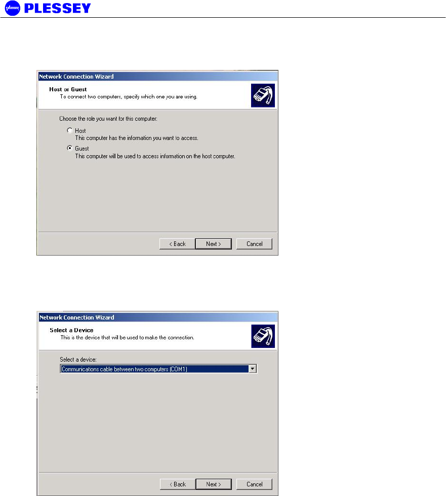
1. Select the Make New Connection menu item.
Win2000 & Win-XP
MDR2400/5800-SR, Orion2410/5810-SRi and Orion 5825-SR
862-01881 Issue 12c Page 81
2. Select the Connect directly to another computer and press the Next button.
Win2000
Win-XP
MDR2400/5800-SR, Orion2410/5810-SRi and Orion 5825-SR
862-01881 Issue 12c Page 82
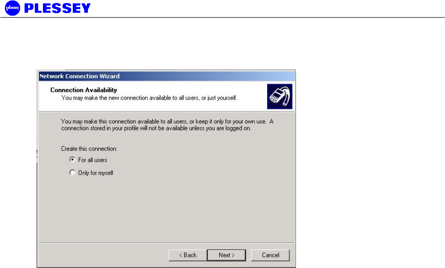
3. Set the dialup connection to connect as Guest and press the Next button.
Win2000 & Win-XP
4. Select the COM port you intend to use to connect to the radio from the Select Device
dropdown box and press the Next button. In Windows XP, this window is preceded by Step 6
below.
Win2000 & Win-XP
MDR2400/5800-SR, Orion2410/5810-SRi and Orion 5825-SR
862-01881 Issue 12c Page 83
5. Select the users that must be able to use this dialup connection and press the Next button.
Win2000 & Win-XP
MDR2400/5800-SR, Orion2410/5810-SRi and Orion 5825-SR
862-01881 Issue 12c Page 84
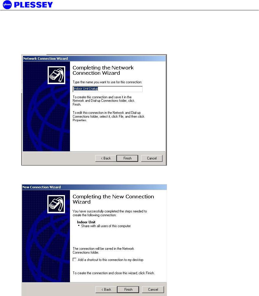
6. Enter the name of this dialup connection and press the Finish button. This name may be any
name of your choice. The connection is now installed, but its properties must still be configured.
This window is displayed earlier in Windows XP.
Win2000 & Win-XP
7. Finish installing the connection (Windows XP only)
Win-XP
MDR2400/5800-SR, Orion2410/5810-SRi and Orion 5825-SR
862-01881 Issue 12c Page 85
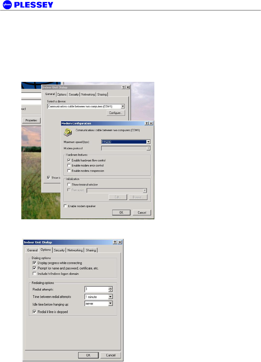
8. Browse to the newly added connection under the Network and Dial-Up connections menu
item of Windows, and right-click on the connection with your mouse. Select the Properties item
from the pop-up menu to bring up the properties window below. Now click on the Configure
button below the Select a Device combo box in the General properties tab window to bring up the
Modem Configuration box below. Make sure that all the settings on your PC are the same is in
this window (Maximum speed: 115200 bps & hardware flow control enabled). Now press the OK
button.
Win2000 & Win-XP
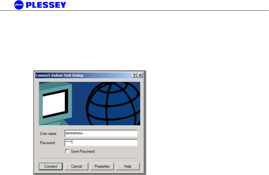
9. In the Options properties box below, select Redial if line is dropped and press the OK button.
Win2000 & Win-XP
MDR2400/5800-SR, Orion2410/5810-SRi and Orion 5825-SR
862-01881 Issue 12c Page 86
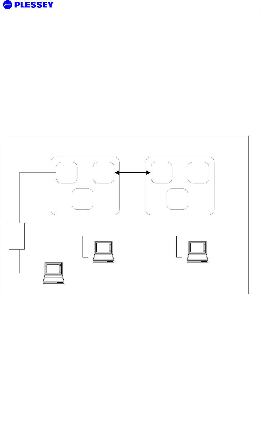
10. Browse to the newly added connection under the Network and Dial-Up connections menu
item of Windows, and left-click on the connection with your mouse. This will bring up the
connection window below. The values of the Username and Password fields does not matter,
press Connect to dial into the radio once the dialup cable has been plugged into the Digital Indoor
Unit and the PC.
Win2000 & Win-XP

MDR2400/5800-SR, Orion2410/5810-SRi and Orion 5825-SR
862-01881 Issue 12c Page 87
B Appendix: MANAGEMENT OF THE MDR2400-SR MDR5800-SR
and the Orion 5825-sr
All management of the MDR and Orion products are implemented using SNMP (Simple
Network Management Protocol), an open standard. The products can be managed by:
1. Standard SNMP managers such as HP OpenView or SNMPc i.e. there is Open Network
Management compatibility.
2. For rapid product installation, the NMS GUI Application (hereafter referred to as the
NMS-GA) provides extensive management functions on site and, via the microwave
radio link, can be used to access the MDR / Orion station on the opposite side of the
link. The NMS-GA is a software application that runs on a PC workstation such as a
laptop or notebook computer that is connected to an MDR / Orion Digital Indoor Unit
serial port (DB9 DTE) or an Ethernet connection (10BaseT DTE), both accessed via the
DIU front-panel.
B.1 SNMP and the MDR / Orion
Use of SNMP within the product allows remote: configuration, monitoring of performance,
notification of alarms and firmware upgrades via an IP-network. Within an IP network
supporting routing of IP data, the radios can be supported from any remote location. The
product can be accessed via the Internet if the necessary gateways are provided. A
GSM/PCS modem dial-up capability provides another remote management option.
The Digital Indoor Units have built-in SNMP agents and an extensive MIB (Management
Information Base). The MDR /Orion product uses SNMP V1 (RFC1155, 1157). The user
has access to an Enterprise MIB (obtainable though customer services) and MIB II (RFC
1213).
Access to the MIB via the DIU SNMP agent is via Ethernet (10BaseT interface on the
product's front panel) or PPP (RFC 1661) via the product's serial channel Element Manager
port. The use of SNMP provides flexibility for operators with central equipment monitoring.
It provides management access to radio configuration (all data interfaces), interface status
and statistics, fault and maintenance information.
SNMP security (if enabled) is ensured by using a login and password to give the user
"administrator" or "standard user" rights. The "standard user rights" option limits the ability
to SET MIB variables.
NOTE Secure SNMP is not longer supported.
The product has threshold-based alarm generation (there is an extensive SNMP trap list
with a trap filter that is adjustable via SNMP). Network access (wired or wireless i.e.
GSM/PCS Modem) allows over-the-air remote firmware uploading (FTP) with a load
verification (and reversion) capability.
There are three principle requirements to use SNMP with the MDR / Orion Radio Stations.

MDR2400/5800-SR, Orion2410/5810-SRi and Orion 5825-SR
862-01881 Issue 12c Page 88
1. A Management Station that runs a SNMP Management Software package that is
installed on a networked or stand-alone PC that can be connected to an Digital Indoor
Unit either using a serial connection or an Ethernet connection. From the Management
station, the agents within the Digital Indoor Units can be configured or polled for
information.
2. Agent: The agent accepts SNMP GET, SET or GET-NEXT commands from the
Management Application software and collects or adjusts information from the Digital
Indoor Unit's MIB.
3. Management Information Base (MIB): the MIB is a database that is accessed based on
the OID (object ID) the SNMP Manager has chosen. The Digital Indoor Unit uses an
Enterprise MIB and a standard MIB (MIB II) to store or allow access to information
relevant to the MDR / Orion link.

MDR2400/5800-SR, Orion2410/5810-SRi and Orion 5825-SR
862-01881 Issue 12c Page 89
B.2 The MIB Elements – OID (Object ID) DESCRIPTIONS
Object ID Object name Object Type
Access
Rights Description
.1316 plessey
.1316.1 products
.1316.1.1 digitalradio
.1316.1.1.1 mdrmte
.1316.1.1.1.1 mdrmtePerformance
.1316.1.1.1.2 mdrmteConfiguration
.1316.1.1.1.3 mdrmteFault
.1316.1.1.1.4 mdrmteAccess
.1316.1.1.1.5 mdrmteRelayOutputs
.1316.1.1.1.6 mdrmteOptoInputs
.1316.1.1.1.1.1 mdrmtePayloadPerf
.1316.1.1.1.1.1.1 mdrmtePpTable SEQUENCE not-accessible
.1316.1.1.1.1.1.1.1 mdrmtePpEntry MdrmtePpEntry not-accessible
.1316.1.1.1.1.1.1.1.1 mdrmtePpIndex INTEGER read-only
.1316.1.1.1.1.1.1.1.2 mdrmtePpLOS INTEGER read-only
A Loss of Signal has been
detected on the input to a
tributary - there is one for
each tributary (0, 1, 2, 3,
...)
.1316.1.1.1.1.1.1.1.3 mdrmtePpAIS INTEGER read-only
An Alarm Indication Signal
has been detected on the
input to a tributary - there
is one for each tributary (0,
1, 2, 3, ...)
.1316.1.1.1.1.1.2 mdrmteCrcErrors INTEGER read-only
The number of CRC4 or
CRC6 errors seen on the
selected tributary since the
last time errors were
cleared.
.1316.1.1.1.1.1.3 mdrmteCrcTribSelect INTEGER read-write
The tributary selected for
CRC checking.
.1316.1.1.1.1.1.4 mdrmteCrcLock INTEGER read-only
Indication of whether the
CRC checking algorithm
has locked onto a CRC
frame signature in the
payload data.
.1316.1.1.1.1.1.5 mdrmteCrcEbitCnt INTEGER read-only
Reflects the number of
assertions of the 'E' bits in
selected tributary.
.1316.1.1.1.1.2 mdrmteRFLinkPerf
.1316.1.1.1.1.2.1 mdrmteCarrierDetect INTEGER read-only
Indicates if a RF Carrier
has been detected by the
RF Unit - if so, the header
in the RF Packet has been
identified as a potential
valid packet - note
however, that it could be
received from another
transmitter that uses the
same header format
.1316.1.1.1.1.2.2 mdrmteRSSI Gauge read-only
A dBm value
representative of the
received signal level. The
value detected is
representative of the level
that would be measured
should a spread spectrum
signal be input at the RF
Unit's Diplexer RF Port - a
CW (Continuous Wave)
signal will appear to be 20
dB higher

MDR2400/5800-SR, Orion2410/5810-SRi and Orion 5825-SR
862-01881 Issue 12c Page 90
Object ID Object name Object Type
Access
Rights Description
.1316.1.1.1.1.2.3 mdrmteCurrentPER DisplayString read-only
This is the current Packet
Error Rate and is based
on the number of
uncorrectable
packets/blocks being
detected by the FEC
(Forward Error Correction)
circuitry within the Digital
Indoor Unit (based of the
number of errored packets
divided by the total
number of packets
transmitted in a
measurement period of
250msec)
.1316.1.1.1.1.2.4 mdrmteMaximizedPER DisplayString read-only
This is the maximum
Packet Error Rate
detected during the last
measurement period,
based number of
maximum number
.1316.1.1.1.1.2.5 mdrmteLinkUnavailable INTEGER read-only
Based on G.826 criteria,
this MIB element indicates
RF Link Availability/Non-
availability
.1316.1.1.1.1.2.6 mdrmteFrameUnlock INTEGER read-only
The data that is
transmitted across the RF
Link is conveyed in a
frame, compiled within
.1316.1.1.1.1.2.7 mdrmteRemoteFrameUnlock INTEGER read-only
Frame-lock
(mdrmteFrameUnlock) as
seen by the other end of
the link is fed back here.
.1316.1.1.1.1.2.8 mdrmteErrSecRatioExceeded INTEGER read-only
The ESR is a ratio of the
number of Errored
seconds (one second
periods within
.1316.1.1.1.1.2.9 mdrmteSevErrSecRatioExceeded INTEGER read-only
The SESR is a ratio of the
number of Severely
Errored seconds (one
second periods within
.1316.1.1.1.1.2.10 mdrmteBkgrndBlkErrRatioExceeded INTEGER read-only
The BBER is a ratio of the
number of uncorrectable
blocks/packets received
.1316.1.1.1.1.2.11 mdrmteMinorPERExceeded INTEGER read-only
This parameter indicates if
the minor packet
(uncorrectable by FEC)
error rate has been
exceeded based on the
defined
.1316.1.1.1.1.2.12 mdrmteMajorPERExceeded INTEGER read-only
This parameter indicates if
the major packet
(uncorrectable by FEC)
error rate has been
exceeded based on the
defined
.1316.1.1.1.1.2.13 mdrmteCriticalPERExceeded INTEGER read-only
This parameter indicates if
the critical packet
(uncorrectable by FEC)
error rate has been
exceeded based on the
defined
.1316.1.1.1.1.2.14 mdrmtePrevParamsRestored INTEGER read-only
Indicates if autorecovery
for the RF Unit settings
had to be invoked
.1316.1.1.1.1.2.15 mdrmteAveragePER DisplayString read-only
This is the current Average
Packet Error Rate and is
based on the number of
.1316.1.1.1.1.2.16 mdrmteStartSweep INTEGER read-write
This is used to start the
spectral RSSI sweep.
.1316.1.1.1.1.2.17 mdrmteRssiSpectrum DisplayString read-only
This contains the results of
the sweep through the
spectum of
.1316.1.1.1.1.3 mdrmteG826

MDR2400/5800-SR, Orion2410/5810-SRi and Orion 5825-SR
862-01881 Issue 12c Page 91
Object ID Object name Object Type
Access
Rights Description
.1316.1.1.1.1.3.1 mdrmteStatus INTEGER read-only
Indicates if 'G.826-like'
errored, severely errored
and unavailable
.1316.1.1.1.1.3.2 mdrmteTotalSeconds Counter read-only
Indicates the total number
of seconds, both available
and unavailable
.1316.1.1.1.1.3.3 mdrmteAvailableSeconds Counter read-only
A period of unavailable
time begins at the onset of
ten consecutive SES
events.
.1316.1.1.1.1.3.4 mdrmteUnavailableSeconds Counter read-only
A period of unavailable
time begins at the onset of
ten consecutive SES
events.
.1316.1.1.1.1.3.5 mdrmteErroredSeconds Counter read-only
A one second period with
one or more errored
packets(uncorrectable
packets) or at least one
defect
.1316.1.1.1.1.3.6 mdrmteSeverelyErroredSeconds Counter read-only
A one-second period
which contains > 30%
errored blocks or at least
one defect. SES is a
subset of ES.
.1316.1.1.1.1.3.7 mdrmteErroredBlocks Counter read-only
A packet which has been
identified as containing
uncorrectable bits by the
FEC circuitry
.1316.1.1.1.1.3.8 mdrmteBackgroundBlockErrors Counter read-only
An errored block not
occurring as part of a
SES.
.1316.1.1.1.1.3.9 mdrmteErroredSecondsRatio DisplayString read-only
The ratio of ES to total
seconds in available time
during a fixed
measurement interval.
.1316.1.1.1.1.3.10
mdrmteSeverelyErroredSecondsRat
io DisplayString read-only
The ratio of SES to total
seconds in available time
during a fixed
measurement interval.
.1316.1.1.1.1.3.11 mdrmteBackgroundBlockErrorRatio DisplayString read-only
The ratio of Background
Block Errors (BBE) to total
blocks in available time
.1316.1.1.1.1.3.12 mdrmteDeprecated2 INTEGER write-only Deprecated
.1316.1.1.1.1.3.13 mdrmteCorrectedSymbols INTEGER read-only
This parameter lists the
number of corrected
symbols i.e. those
corrected by the FEC
.1316.1.1.1.1.4 mdrmteCounters
.1316.1.1.1.1.4.1 mdrmteLostEthRxPkts Counter read-only
Indicates the total number
of times an ethernet
packet could not be
buffered
.1316.1.1.1.1.4.2 mdrmteLostLinkRxPkts Counter read-only
Indicates the total number
of times a link packet
could not be buffered
.1316.1.1.1.1.4.3 mdrmteLostWaySideTxPkts Counter read-only
Indicates the total number
of times a wayside packet
could not be buffered
.1316.1.1.1.1.4.4 mdrmteScc1FullCnt Counter read-only
Indicates the total number
of times SCC1 was full to
capacity
.1316.1.1.1.1.4.5 mdrmteScc2FullCnt Counter read-only
Indicates the total number
of times SCC2 was full to
capacity
.1316.1.1.1.1.4.6 mdrmteScc1UnderrunCnt Counter read-only
Indicates the total number
of times SCC1 ran out of
BDs
.1316.1.1.1.1.4.7 mdrmteScc2UnderrunCnt Counter read-only
Indicates the total number
of times SCC2 ran out of
BDs
.1316.1.1.1.1.4.8 mdrmteScc2RxBdAbortCnt Counter read-only
Indicates the total number
of times SCC2 received an
aborted frame

MDR2400/5800-SR, Orion2410/5810-SRi and Orion 5825-SR
862-01881 Issue 12c Page 92
Object ID Object name Object Type
Access
Rights Description
.1316.1.1.1.1.4.9 mdrmteScc2RxBdNonOctCnt Counter read-only
Indicates the total number
of times SCC2 received a
Non octet aligned frame
.1316.1.1.1.1.4.10 mdrmteScc2RxBdCrcCnt Counter read-only
Indicates the total number
of times SCC2 received a
frame with a CRC error
.1316.1.1.1.1.4.11 mdrmteEtherTxRetries Counter read-only
Indicates the total number
of (collisions) packets that
were retransmitted on
ethernet
.1316.1.1.1.1.4.12 mdrmteEtherTxDeferCnt Counter read-only
Indicates the total number
of frames deferred due to
early collisions on ethernet
.1316.1.1.1.1.4.13 mdrmteEtherTxHeartBeatCnt Counter read-only
Indicates the total number
of times the collision inup
was not asserted on
ethernet
.1316.1.1.1.1.4.14 mdrmteEtherTxLateCollisions Counter read-only
Indicates the total number
of late collisions on
ethernet
.1316.1.1.1.1.4.15 mdrmteEtherReTxLimit Counter read-only
Indicates the total number
of times the retransmission
limit was reached on
ethernet
.1316.1.1.1.1.4.16 mdrmteEtherTxUnderrun Counter read-only
Indicates the total number
of buffer underruns on
ethernet
.1316.1.1.1.1.4.17 mdrmteEtherTxCarrierLost Counter read-only
Indicates the total number
of times carrier was lost on
ethernet
.1316.1.1.1.1.4.18 mdrmteEtherRxLenErr Counter read-only
Indicates the total number
of frame length violations
received on ethernet
.1316.1.1.1.1.4.19 mdrmteEtherRxNonOctet Counter read-only
Indicates the total number
of non-octet aligned
frames received on
ethernet
.1316.1.1.1.1.4.20 mdrmteEtherRxShort Counter read-only
Indicates the total number
of (too) short frames
received on ethernet
.1316.1.1.1.1.4.21 mdrmteEtherRxCRCerr Counter read-only
Indicates the total number
of CRC errored frames
received on ethernet
.1316.1.1.1.1.4.22 mdrmteEtherRxOverrun Counter read-only
Indicates the total number
of receiver overruns
received on ethernet
.1316.1.1.1.1.4.23 mdrmteEtherRxCollision Counter read-only
Indicates the total number
of collisioned frames
received on ethernet
.1316.1.1.1.1.4.24 mdrmteEtherJunkFrames Counter read-only
Indicates the total number
of invalid frames received
on ethernet
.1316.1.1.1.1.4.25 mdrmteEtherShortFrames Counter read-only
Indicates the total number
of times the Ethernet
frame received was too
short.
.1316.1.1.1.1.4.26 mdrmteEtherTxBdsFull Counter read-only
Indicates the total number
of times the ethernet Tx
BD queue was too full to
insert data
.1316.1.1.1.1.4.27 mdrmteEtherRxPauseCnt Counter read-only
Indicates the total number
of times the ethernet
receiver was disabled due
to lack of buffers.
.1316.1.1.1.1.4.28 mdrmteIdma1InUse Counter read-only
Indicates the total number
of times IDMA controller 1
was already in use.
memcpy() was used
instead.

MDR2400/5800-SR, Orion2410/5810-SRi and Orion 5825-SR
862-01881 Issue 12c Page 93
Object ID Object name Object Type
Access
Rights Description
.1316.1.1.1.1.4.29 mdrmteIdma2InUse Counter read-only
Indicates the total number
of times IDMA controller 2
was already in use.
memcpy() was used
instead.
.1316.1.1.1.1.4.30 mdrmteLinkKnQueueFull Counter read-only
Indicates the total number
of times a Kwiknet frame
was deferred due to a lack
of space in the AMX link
queue.
.1316.1.1.1.1.4.31 mdrmteLinkTxBdsFull Counter read-only
Indicates the total number
of times the Rf Link Tx BD
queue was too full to insert
data
.1316.1.1.1.1.4.32 mdrmteKnEtherFramesLost Counter read-only
Indicates the total number
of times the Kwiknet
queue was too full to insert
Ethernet data
.1316.1.1.1.1.4.33 mdrmteKnCraftFramesLost Counter read-only
Indicates the total number
of times the Kwiknet
queue was too full to insert
SCC4 data
.1316.1.1.1.1.4.34 mdrmteKnLinkFramesLost Counter read-only
Indicates the total number
of times the Kwiknet
queue was too full to insert
SCC2 data
.1316.1.1.1.1.4.35 mdrmteKnFramesTooShort Counter read-only
Indicates the total number
of times the Kwiknet buffer
allocated was too short.
.1316.1.1.1.1.4.36 mdrmteLinkVoidFrames Counter read-only
Indicates the total number
of overwritten frames
received on the wireless
PPP link
.1316.1.1.1.1.4.37 mdrmteLinkRxPauseCnt Counter read-only
Indicates the total number
of times the link receiver
was disabled due to lack
of buffers.
.1316.1.1.1.1.4.38 mdrmteRelayServerRestarts Counter read-only
Indicates the total number
of times the Relay
scripting server restarted.
.1316.1.1.1.1.4.39 mdrmteRelayClientRestarts Counter read-only
Indicates the total number
of times the Relay
scripting client restarted.
.1316.1.1.1.1.4.40 mdrmteMuxEtherErrors Counter read-only
The number of Ethernet
errors reported by the
FPGA
.1316.1.1.1.1.4.41 mdrmteMuxBlockErrors Counter read-only
The number of Block
errors reported by the
FPGA
.1316.1.1.1.1.4.42 mdrmteOuRxEtherCRCerrors Counter read-only
The number of Ethernet
errors reported by the
FPGA on the RFU
.1316.1.1.1.1.5 mdrmteResetAllPerfData INTEGER write-only
Reset all parameters
associated with Packet
Error and G.826
measurements for the RF
Link
.1316.1.1.1.2.1 mdrmtePayloadConf
.1316.1.1.1.2.1.1 mdrmteDataRate INTEGER read-write
Configure the tributary
data interface rate - either
E1 or T1
.1316.1.1.1.2.1.2 mdrmteLineCodeType INTEGER read-only Deprecated
.1316.1.1.1.2.1.3 mdrmtePcTable SEQUENCE not-accessible
.1316.1.1.1.2.1.3.1 mdrmtePcEntry MdrmtePcEntry not-accessible
.1316.1.1.1.2.1.3.1.1 mdrmtePcIndex INTEGER read-only
.1316.1.1.1.2.1.3.1.2 mdrmtePcLabel DisplayString read-write
E1/T1 Payload
configuration tributary
label
.1316.1.1.1.2.1.3.1.3 mdrmtePcActive INTEGER read-write
Defines whether tributaries
are active or inactive
.1316.1.1.1.2.1.4 mdrmteLineEncodingTable SEQUENCE not-accessible

MDR2400/5800-SR, Orion2410/5810-SRi and Orion 5825-SR
862-01881 Issue 12c Page 94
Object ID Object name Object Type
Access
Rights Description
.1316.1.1.1.2.1.4.1 mdrmteLineEncodingEntry
MdrmteLineEncoding
Entry not-accessible
.1316.1.1.1.2.1.4.1.1 mdrmteLineEncodingIndex INTEGER read-only
.1316.1.1.1.2.1.4.1.2 mdrmteLineEncodingTribSelect INTEGER read-only
Selects the trib, or group
of tributaries to which
encoding applies
.1316.1.1.1.2.1.4.1.3 mdrmteLineEncoding INTEGER read-write
Defines the line code
types for the tributaries,
either HDB3 or AMI for E1
.1316.1.1.1.2.2 mdrmteRFLinkConf
.1316.1.1.1.2.2.1 mdrmteTxPower INTEGER read-write
Allows setup of the output
power available at the
diplexer port of the RF Unit
.1316.1.1.1.2.2.2 mdrmteBandPlan INTEGER read-write
The MDR5800 RF Units
operate in the 5.725 GHz
to 5.850 GHz ISM
frequency band.
.1316.1.1.1.2.2.3 mdrmteTxFrequencyPlanD INTEGER read-write
Frequency plan D allows
independent control of
transmit and receive
frequencies.
.1316.1.1.1.2.2.4 mdrmteRxFrequencyPlanD INTEGER read-write
Refer to the
mdrmteTxFrequencyPlanD
description
.1316.1.1.1.2.2.5 mdrmteTransmitBand INTEGER read-only
This value is read from the
RF Unit via the Digital
Indoor Unit and defines
whether it transmits in the
.1316.1.1.1.2.2.6 mdrmteReserved2 INTEGER read-write
.1316.1.1.1.2.2.7 mdrmteRegulations INTEGER read-only
This parameter is read
from the RF Unit via the
Digital Indoor Unit and
defines regulatory
compliance of the RF Unit
.1316.1.1.1.2.2.8 mdrmteAutoRecovery INTEGER read-write
This feature is used if the
user is installing a link
from one side and there is
no assistance on the
opposite side of the link. It
mitigates against the link
failing and not being able
to be
.1316.1.1.1.2.2.9 mdrmteOURateOverride INTEGER read-write Depracated
.1316.1.1.1.2.2.10 mdrmteOUDataRate INTEGER read-write
A setable rate that allows
a reduced transfer data
rate over the RF Link
.1316.1.1.1.2.2.11 mdrmteTxFrequencyCurrent INTEGER read-only
This value [MHz] is read
back from the RF Unit and
defines the transmit
frequency of the RF Unit
.1316.1.1.1.2.2.12 mdrmteRxFrequencyCurrent INTEGER read-only
This value [MHz] is read
back from the RF Unit and
defines the receive
frequency of the RF Unit
.1316.1.1.1.2.2.13 mdrmteNonAutoBandPlan INTEGER read-write
Same as
mdrMTEBandPlan setting
in this MIB group except
Autorecovery is not
enabled - this allows
control of the Outdoor
.1316.1.1.1.2.2.14 mdrmteNonAutoTxFreqPlanD INTEGER read-write
Same as
mdrTxFrequencyPlanD
setting in this MIB group
except autorecovery is not
enabled - this allows
control of the Outdoor

MDR2400/5800-SR, Orion2410/5810-SRi and Orion 5825-SR
862-01881 Issue 12c Page 95
Object ID Object name Object Type
Access
Rights Description
.1316.1.1.1.2.2.15 mdrmteNonAutoRxFreqPlanD INTEGER read-write
Same as
mdrRxFrequencyPlanD
setting in this MIB group
except autorecovery is not
enabled - this allows
control of the Outdoor
.1316.1.1.1.2.2.16 mdrmteNonAutoTxPower INTEGER read-write
Same as mdrTxPower
setting in this MIB group
except autorecovery is not
enabled - this allows
control of the Outdoor
.1316.1.1.1.2.2.17 mdrmteRadioType INTEGER read-only
This value is read from the
RF Unit via the Digital
Indoor Unit and defines
.1316.1.1.1.2.2.18 mdrmteSevereErrorMargin INTEGER read-write
Defines the percentage
threshold (1-99) used
when calculating in a one
second period
.1316.1.1.1.2.2.19 mdrmteTimedMute INTEGER write-only
Initiates muting of
transmitted signal for a
short period to facilitate
spectral analysis.
.1316.1.1.1.2.3 mdrmteServiceChannel
.1316.1.1.1.2.3.1 mdrmteScDataRate INTEGER read-write
Bit rate used across the
wayside service channel
link
.1316.1.1.1.2.3.2 mdrmteScDataBits INTEGER read-write
The data width - can be 7
or 8 bits
.1316.1.1.1.2.3.3 mdrmteScParity INTEGER read-write
Serial channel - set to
none, odd or even
.1316.1.1.1.2.3.4 mdrmteScStopBits INTEGER read-write
The nuber of stop bits can
be set to 1 or 2
.1316.1.1.1.2.3.5 mdrmteScFlowControl INTEGER read-write
Either hardware or no flow
control is used
.1316.1.1.1.2.3.6 mdrmteScStatusDump INTEGER read-write
Allows the wayside service
(serial) channel to be used
as a diagnostics port
.1316.1.1.1.2.4 mdrmteGeneral
.1316.1.1.1.2.4.1 mdrmteStationName DisplayString read-write
The station name is stored
in the Digital Indoor Unit in
nonvolatile memory
.1316.1.1.1.2.4.2 mdrmteIUSerialNumber DisplayString read-only
An electronic serial
number is read from the
Digital Indoor Unit - this
number is unique
.1316.1.1.1.2.4.3 mdrmteIUFirmwareVersion DisplayString read-only
The Digital Indoor Unit
firmware number is the
version of application
firmware that is loaded
into
.1316.1.1.1.2.4.4 mdrmteIUBootkernelVersion DisplayString read-only
The Digital Indoor Unit
bootkernel version is the
version of boot firmware
that is loaded into
.1316.1.1.1.2.4.5 mdrmteOUBarCode INTEGER read-only
The RF Unit bar-code
number is programmed
into the RFU at time of
manufacture and is read
via the
.1316.1.1.1.2.4.6 mdrmteOUPICFirmwareVersion DisplayString read-only
The RF Unit PIC firmware
number is programmed
into the RFU at time of
manufactute and is read
via the
.1316.1.1.1.2.4.7 mdrmteOUPayloadSupport INTEGER read-only Deprecated
.1316.1.1.1.2.4.8 mdrmteDate DisplayString read-write
This is a date record that
is recovered from the
Digital Indoor Unit's Real
Time Clock

MDR2400/5800-SR, Orion2410/5810-SRi and Orion 5825-SR
862-01881 Issue 12c Page 96
Object ID Object name Object Type
Access
Rights Description
.1316.1.1.1.2.4.9 mdrmteTime DisplayString read-write
This is a time record that is
recovered from the Digital
Indoor Unit's Real Time
Clock
.1316.1.1.1.2.4.10 mdrmteNOVRAMInit INTEGER read-write
If activated, the
Nonvolatile memory is
initialised to a set of
default parameters
.1316.1.1.1.2.4.11 mdrmteFECBypass INTEGER read-write
This is primarily a
laboratory test entry used
to control whether the FEC
circuitry within the
.1316.1.1.1.2.4.12 mdrmteFECCorrectableSymbols INTEGER read-write
This is primarily a
laboratory test entry used
to control the FEC
correction power - 20
parity symbols
.1316.1.1.1.2.4.13 mdrmteTribCode DisplayString read-write
This is a text entry code
(80 characters ie 40 bytes)
used to allow activation of
tributaries on the Digital
Indoor Units.
.1316.1.1.1.2.4.14 mdrmteIndoorUnitBarCodeNumber DisplayString read-write
This is a text entry code
used to allow storage of
the Digital Indoor Unit's
bar code serial number (as
seen on the outside of the
.1316.1.1.1.2.4.15 mdrmteIndoorUnitPCBrevision INTEGER read-write
This is a numeric entry
code used to reflect the
PCB revision number and
modification status.
.1316.1.1.1.2.4.16 mdrmteLocation DisplayString read-write
The station location is
stored in the Digital Indoor
Unit in nonvolatile memory
.1316.1.1.1.2.4.17 mdrmteOnePlusOne INTEGER read-write
Enables 'one-plus-one'
dual-redundant (non-
hitless) operation
.1316.1.1.1.2.4.18 mdrmteMaxTribs INTEGER read-only
How many tribs can be
used with the current trib
code.
.1316.1.1.1.2.4.19 mdrmteDefaultConfig INTEGER write-only
Allows one to set one of
four default-configurations.
.1316.1.1.1.2.4.20 mdrmteTotalTribs INTEGER read-only
How many tribs in total on
this version of IDU
motherboard.
.1316.1.1.1.2.4.21 mdrmteCustomConfigSet INTEGER read-write
Changes the way in which
the default configurations
work by pre-loading
.1316.1.1.1.2.4.22 mdrmteFpgaVersion INTEGER read-only
Firmware version of the
FPGA.
.1316.1.1.1.2.4.23 mdrmteOuCommsRate INTEGER read-write
Data-rate of the ethernet
link between the DIU and
the RFU.
.1316.1.1.1.2.4.24 mdrmteHdlcRateCap INTEGER read-write
Maximum Data-rate of the
HDLC link between the
DIU's (Mbit/sec + 1)
.1316.1.1.1.2.4.25 mdrmteOUSerialNo DisplayString read-only
The RF Unit serial number
is programmed into the
RFU at time of
manufacture and is read
via the
.1316.1.1.1.2.4.26 mdrmteApVersion DisplayString read-only
The Firmware version
number of the Atmel
processor
.1316.1.1.1.2.5 mdrmteFirmware
.1316.1.1.1.2.5.1 mdrmteFTPServerStatus INTEGER read-write
This allows
activation/deactivation of
the FTP server that runs in
the Digital Indoor Unit and
is
.1316.1.1.1.2.5.2 mdrmteFlashNewFirmware INTEGER read-write
This entry determines the
time when the new version
of firmware will be
activated

MDR2400/5800-SR, Orion2410/5810-SRi and Orion 5825-SR
862-01881 Issue 12c Page 97
Object ID Object name Object Type
Access
Rights Description
.1316.1.1.1.2.5.3 mdrmtePlatformSupport DisplayString read-only
This indicates the
hardware types supported
by the firmware:
.1316.1.1.1.2.6 mdrmteOutdoorUnit
.1316.1.1.1.2.6.1 mdrmteOuPersonalityTable SEQUENCE not-accessible
.1316.1.1.1.2.6.1.1 mdrmteOuPersonalityEntry
MdrmteOuPersonality
Entry not-accessible
.1316.1.1.1.2.6.1.1.1 mdrmteOuPersonalityIndex INTEGER read-only
.1316.1.1.1.2.6.1.1.2 mdrmteOuPersonalityActive INTEGER read-write
Indicates whether this
particular RFU personality
is selected.
.1316.1.1.1.2.6.1.1.3 mdrmteOuPersonalityDataRate INTEGER read-only
Maximum raw data rate of
the personality.
.1316.1.1.1.2.6.1.1.4 mdrmteOuPersonalityModulation INTEGER read-only Modulation type.
.1316.1.1.1.2.6.1.1.5 mdrmteOuPersonalityFpgaVersion INTEGER read-only FPGA version.
.1316.1.1.1.2.6.1.1.6 mdrmteOuPersonalityRssiComp INTEGER read-only
RSSI compensation factor
used by the RFU
.1316.1.1.1.2.6.1.1.7 mdrmteOuPersonalityMinTxFreq INTEGER read-only
Lowest allowed Tx
frequency
.1316.1.1.1.2.6.1.1.8 mdrmteOuPersonalityMaxTxFreq INTEGER read-only
Highest allowed Tx
frequency
.1316.1.1.1.2.6.1.1.9 mdrmteOuPersonalityMinRxFreq INTEGER read-only
Lowest allowed Rx
frequency
.1316.1.1.1.2.6.1.1.10 mdrmteOuPersonalityMaxRxFreq INTEGER read-only
Highest allowed Rx
frequency
.1316.1.1.1.2.6.1.1.11 mdrmteOuPersonalityPlanATxFreq INTEGER read-only Band plan A Tx frequency
.1316.1.1.1.2.6.1.1.12 mdrmteOuPersonalityPlanARxFreq INTEGER read-only Band plan A Tx frequency
.1316.1.1.1.2.6.1.1.13 mdrmteOuPersonalityPlanBTxFreq INTEGER read-only Band plan B Tx frequency
.1316.1.1.1.2.6.1.1.14 mdrmteOuPersonalityPlanBRxFreq INTEGER read-only Band plan B Rx frequency
.1316.1.1.1.2.6.1.1.15 mdrmteOuPersonalityPlanCTxFreq INTEGER read-only Band plan C Rx frequency
.1316.1.1.1.2.6.1.1.16 mdrmteOuPersonalityPlanCRxFreq INTEGER read-only Band plan C Rx frequency
.1316.1.1.1.2.6.1.1.17 mdrmteOuPersonalityMaxTxPower INTEGER read-only
Maximum allowed
Transmit Power
.1316.1.1.1.2.6.1.1.18 mdrmteOuPersonalityMinTxPower INTEGER read-only
Minimum allowed Transmit
Power
.1316.1.1.1.2.6.1.1.19 mdrmteOuPersonalityDefTxPower INTEGER read-only Default Transmit Power
.1316.1.1.1.2.6.1.1.20 mdrmteOuPersonalityDescription DisplayString read-only
Verbal description of this
personality
.1316.1.1.1.2.6.2 mdrmteOuPersonalities INTEGER read-only
The number of FPGA
personalities that the RFU
has programmed
.1316.1.1.1.2.6.3 mdrmteOuActivePersonality INTEGER read-write
The currently active FPGA
personality
.1316.1.1.1.3.1 mdrmteInfo
.1316.1.1.1.3.1.1 mdrmteLEDTable SEQUENCE not-accessible
A group of LEDs on the
front panel of the Digital
Indoor Unit.
.1316.1.1.1.3.1.1.1 mdrmteLEDEntry MdrmteLEDEntry not-accessible
A LED entry containing
objects describing a
particular LED.
.1316.1.1.1.3.1.1.1.1 mdrmteLEDIndex INTEGER read-only
A unique value for each
LED in the Digital Indoor
Unit. Its value
.1316.1.1.1.3.1.1.1.2 mdrmteLEDLabel DisplayString read-only
SYSTEM Green OK,
Orange (RFU/DIU Comms
Error), Red (RFU/DIU
Comms Down).
.1316.1.1.1.3.1.1.1.3 mdrmteLEDState INTEGER read-only
The current state of the
LED - for a detailed
description of functionality,
see the mdrmteLEDLabel
entry

MDR2400/5800-SR, Orion2410/5810-SRi and Orion 5825-SR
862-01881 Issue 12c Page 98
Object ID Object name Object Type
Access
Rights Description
.1316.1.1.1.3.1.1.1.4 mdrmteLEDColour INTEGER read-only
The current colour of the
LED - for a detailed
description of functionality,
see the mdrmteLEDLabel
entry
.1316.1.1.1.3.1.1.1.5 mdrmteLEDHistoricAmberWarning INTEGER read-only
The number of Amber
'blips' that the LED is
flashing
.1316.1.1.1.3.1.1.1.6 mdrmteLEDHistoricRedError INTEGER read-only
The number of Red 'blips'
that the LED is flashing
.1316.1.1.1.3.1.2 mdrmteOutdoorUnitComms INTEGER read-only
Describes the state of
Digital Indoor Unit
communication with the
RF Unit.
.1316.1.1.1.3.1.3 mdrmteOutdoorUnitResetType INTEGER read-only
This message is read from
the RF Unit and identifies
the last reason for a reset
within the
.1316.1.1.1.3.1.4 mdrmteOutdoorUnitLockDetect INTEGER read-only
The transmit RF
synthesizer, receive RF
synthesizer and IF phased
locked loop lock detect
signals
.1316.1.1.1.3.1.5 mdrmtePayloadDrive INTEGER read-only
In a One-Plus-One
configuration, this tells you
if this DIU is driving the
.1316.1.1.1.3.1.6 mdrmteLock INTEGER read-only
In a One-Plus-One
configuration, this tells you
if this DIU is driving the
.1316.1.1.1.3.1.7 mdrmtePeerPayloadDrive INTEGER read-only
In a One-Plus-One
configuration, this tells you
if the peer (standby) is
driving the
.1316.1.1.1.3.1.8 mdrmtePeerLock INTEGER read-only
In a One-Plus-One
configuration, this tells you
if the peer (standby) is
driving the
.1316.1.1.1.3.1.9 mdrmteOuEtherRate INTEGER read-only
The current (actual) Data-
rate of the ethernet link
between the DIU and the
RFU.
.1316.1.1.1.3.2 mdrmteSelfTest
.1316.1.1.1.3.2.1 mdrmteFlash INTEGER read-only
Identifies pass/fail status
of the Digital Indoor Unit's
application flash
.1316.1.1.1.3.2.2 mdrmteDRAM INTEGER read-only
Identifies pass/fail status
of the Digital Indoor Unit's
Dynamic RAM
.1316.1.1.1.3.2.3 mdrmteSRAM INTEGER read-only
Identifies pass/fail status
of the Digital Indoor Unit's
Static RAM
.1316.1.1.1.3.2.4 mdrmteLineInterface INTEGER read-only
Identifies pass/fail status
of the Digital Indoor Unit's
Line Interface IC
.1316.1.1.1.3.2.5 mdrmteFPGA INTEGER read-only
Identifies pass/fail status
of the Digital Indoor Unit's
FPGA interface registers
to the microprocessor
.1316.1.1.1.3.2.6 mdrmteFEC INTEGER read-only
Identifies pass/fail status
of the Digital Indoor Unit's
FEC IC electrical interface
.1316.1.1.1.3.2.7 mdrmteRealTimeClock INTEGER read-only
Identifies pass/fail status
of the Digital Indoor Unit's
Real Time Clock
.1316.1.1.1.3.2.8 mdrmteIndoorUnitResetType INTEGER read-only
This message is read from
the Digital Indoor Unit and
identifies the last reason
for a reset within the
.1316.1.1.1.3.2.9 mdrmteLoopbackMode INTEGER read-write
Entry defines the loopback
mode of a radio station in
terms of loopback at either
.1316.1.1.1.3.2.10 mdrmteLoopbackTimeOut INTEGER read-write
This is the number of
seconds the loopback will
run for until it times out

MDR2400/5800-SR, Orion2410/5810-SRi and Orion 5825-SR
862-01881 Issue 12c Page 99
Object ID Object name Object Type
Access
Rights Description
.1316.1.1.1.3.2.11 mdrmteOuTemperature DisplayString read-only
This is the measured
temperature in the Out-
door unit (if supported) in
degrees Celcius
.1316.1.1.1.3.2.12 mdrmteOuEtherPhy INTEGER read-only
Identifies pass/fail status
of the ethernet phy to the
RFU
.1316.1.1.1.3.2.13 mdrmteEEprom INTEGER read-only
Identifies pass/fail status
of the Digital Indoor Unit's
EEPROM
.1316.1.1.1.3.3 mdrmteTrapManagement
.1316.1.1.1.3.3.1 mdrmteTrapFilter INTEGER read-write
Alarms within the MDR
product are classfied as
critical, major, minor or
informational. The trap
.1316.1.1.1.3.3.2 mdrmteNumberTrapManagers INTEGER read-only
This entry shows the
number of trap managers
allowed
.1316.1.1.1.3.3.3 mdrmteTrapManagerTable SEQUENCE not-accessible
.1316.1.1.1.3.3.3.1 mdrmteTrapManagerEntry
MdrmteTrapManager
Entry not-accessible
.1316.1.1.1.3.3.3.1.1 mdrmteTrapManagerIndex INTEGER read-only
.1316.1.1.1.3.3.3.1.2 mdrmteTrapManagerIP IpAddress read-write
This is the IP address of
the management station
that is set up to detect and
act upon
.1316.1.1.1.3.3.3.1.3 mdrmteTrapManagerComm DisplayString read-write
This is the 'SNMP
community name' used for
dispatch of traps
.1316.1.1.1.3.3.3.1.4 mdrmteTrapManagerActive INTEGER read-write
Defines whether a
particular Trap Manager is
active or inactive
.1316.1.1.1.3.4 mdrmtePerfTrapThreshold
.1316.1.1.1.3.4.1 mdrmteMinorPERThreshold DisplayString read-write
Defines the threshold used
as a checking criterion for
the Minor PER (Packet
Error Rate)
.1316.1.1.1.3.4.2 mdrmteMajorPERThreshold DisplayString read-write
Defines the threshold used
as a checking criterion for
the Major PER (Packet
Error Rate)
.1316.1.1.1.3.4.3 mdrmteCriticalPERThreshold DisplayString read-write
Defines the threshold used
as a checking criterion for
the Critical PER (Packet
Error Rate)
.1316.1.1.1.3.4.4 mdrmteErrSecRatioThreshold DisplayString read-write
Defines the threshold used
as a checking criterion for
the Errored Second Ratio
.1316.1.1.1.3.4.5 mdrmteSevErrSecRatioThreshold DisplayString read-write
Defines the threshold used
as a checking criterion for
the Severely Errored
Second Ratio
.1316.1.1.1.3.4.6 mdrmteBkgrndBlkErrRatioThreshold DisplayString read-write
Defines the threshold used
as a checking criterion for
the Background Block
Error Ratio
.1316.1.1.1.3.5 mdrmteEventLogTable SEQUENCE not-accessible
.1316.1.1.1.3.5.1 mdrmteEventLogEntry
MdrmteEventLogEntr
y not-accessible
.1316.1.1.1.3.5.1.1 mdrmteEventIndex INTEGER read-only
.1316.1.1.1.3.5.1.2 mdrmteEventDate DisplayString read-only
Lists the date on which the
event occurred
.1316.1.1.1.3.5.1.3 mdrmteEventTime DisplayString read-only
Lists the time when the
event occurred
.1316.1.1.1.3.5.1.4 mdrmteEventType INTEGER read-only
Lists the type of event -
informational, minor, major
or critical
.1316.1.1.1.3.5.1.5 mdrmteEventDescription DisplayString read-only
Textual description of the
logged event

MDR2400/5800-SR, Orion2410/5810-SRi and Orion 5825-SR
862-01881 Issue 12c Page 100
Object ID Object name Object Type
Access
Rights Description
.1316.1.1.1.3.6 mdrmteClearEventLog INTEGER write-only
This entry is used to clear
the Event Log
.1316.1.1.1.3.7 mdrmteResetAllFaults INTEGER write-only This entry is used to
.1316.1.1.1.3.8 mdrmteEnableDebug INTEGER read-write
This entry is used to
enable test and debugging
features
.1316.1.1.1.3.9 mdrmteErrorWindow INTEGER read-write
This entry is used to set
the time period in minutes
during
.1316.1.1.1.3.10 mdrmteTrapData DisplayString read-only
Textual description or data
relating to a trap
.1316.1.1.1.3.11 mdrmteLogCorrectedSymbols INTEGER read-write
Enable or disable periodic
logging of corrected
sybmols
.1316.1.1.1.3.13 mdrmteHideHistoricLeds INTEGER read-write
Enable or disable the
'historic' flashing on the
LEDs
.1316.1.1.1.3.12 mdrmteEngineering
.1316.1.1.1.3.12.1 mdrmteDataStreamStatus INTEGER read-only
Status bits for the RF Unit
and tribs during during
production tests.
.1316.1.1.1.3.12.2 mdrmteFramingSchedule INTEGER read-only
The current framing
schedule selected on the
FPGA
.1316.1.1.1.3.12.3 mdrmteFrameTribCnt INTEGER read-only
The number of tribs
supported by the framing
structure in use
.1316.1.1.1.3.12.4 mdrmteIuBackToBack INTEGER read-write
Loop one Digital Indoor
Unit to another without RF
Units for production tests
.1316.1.1.1.3.12.5 mdrmteWaysideFeedsOu INTEGER read-write
Feed the Wayside channel
to the RF Unit for
production tests
.1316.1.1.1.4.1 mdrmteEthernetIPAddress IpAddress read-write
The IP address associated
with product's Ethernet
port.
.1316.1.1.1.4.2 mdrmteEthernetNetMask IpAddress read-write
The netmask associated
with the Ethernet port
.1316.1.1.1.4.3 mdrmteMaxNumUsers INTEGER read-only
If the firmware is compiled
with the security feature
.1316.1.1.1.4.4 mdrmteMaxNumActiveUsers INTEGER read-only
If the firmware is built with
the security feature
switched on, users
.1316.1.1.1.4.5 mdrmteNumActiveUsers Gauge read-only
If the firmware is built with
the security feature
switched on, users
.1316.1.1.1.4.6 mdrmteUserTable SEQUENCE not-accessible Deprecated
.1316.1.1.1.4.6.1 mdrmteUserEntry MdrmteUserEntry not-accessible Deprecated
.1316.1.1.1.4.6.1.1 mdrmteUserIndex INTEGER read-only Deprecated
.1316.1.1.1.4.6.1.2 mdrmteUserName DisplayString read-write
If the firmware is built with
the security feature
switched on, users
.1316.1.1.1.4.6.1.3 mdrmteUserPassword DisplayString write-only
If the firmware is built with
the security feature
switched on, users
.1316.1.1.1.4.6.1.4 mdrmteUserAccessLevel INTEGER read-write
If the firmware is built with
the security feature
switched on, users
.1316.1.1.1.4.6.1.5 mdrmteUserActive INTEGER read-write
Indicates if a user is active
or not based on password
entry
.1316.1.1.1.4.6.1.6 mdrmteUserAdd INTEGER write-only
In security-enabled mode,
allows an administrator to
add users
.1316.1.1.1.4.6.1.7 mdrmteUserDelete INTEGER write-only
In security-enabled mode,
allows an administrator to
delete users

MDR2400/5800-SR, Orion2410/5810-SRi and Orion 5825-SR
862-01881 Issue 12c Page 101
Object ID Object name Object Type
Access
Rights Description
.1316.1.1.1.4.7 mdrmteRFLinkIPAddress IpAddress read-write
PPP IP address for the RF
Link. The user need not
adjust this parameter
.1316.1.1.1.4.8 mdrmteRFLinkNetMask IpAddress read-write
PPP IP netmask for the
RF Link. The user need
not adjust this parameter
.1316.1.1.1.4.9 mdrmteRemoteIPAddress IpAddress read-write
Default PPP IP address
for the other end of the
link. The user need not
adjust this parameter
.1316.1.1.1.4.10 mdrmteElementManagerIPAddress IpAddress read-write
Default PPP IP address
for the the element
manager port - 10.13.1.1
.1316.1.1.1.4.11 mdrmteElementManagerNetMask IpAddress read-write
IP netmask for the
Element Manager PPP
port
.1316.1.1.1.4.12 mdrmteIPNegotiable INTEGER read-write
Determines if the local
PPP IP address is
negotiable or not - does
not need to be adjusted by
.1316.1.1.1.4.13 mdrmtePPPisDefaultRoute INTEGER read-write
Determines if PPP
interface is the default
route - does not need to
be adjusted by
.1316.1.1.1.4.14 mdrmteStaticRouteTable SEQUENCE not-accessible
Manually added static
routes. (Only activated
after system reset)
.1316.1.1.1.4.14.1 mdrmteStaticRouteEntry
MdrmteStaticRouteEn
try not-accessible
.1316.1.1.1.4.14.1.1 mdrmteStaticRouteIndex INTEGER read-only
.1316.1.1.1.4.14.1.2
mdrmteStaticRouteIPAddressDestin
ation IpAddress read-write Ultimate destination
.1316.1.1.1.4.14.1.3 mdrmteStaticRouteIPAddressMask IpAddress read-write
net mask,
255.255.255.255 if
destination is host address
.1316.1.1.1.4.14.1.4
mdrmteStaticRouteIPAddressNextH
op IpAddress read-write Where to forward to
.1316.1.1.1.4.14.1.5
mdrmteStaticRouteInterfaceForNext
Hop INTEGER read-write Interface (net) for nexthop
.1316.1.1.1.4.15 mdrmteBridgeEnable INTEGER read-write
Determines if the system
is to act as a transparent
bridge for all ethernet
packets received.
.1316.1.1.1.4.16 mdrmteEthernetFullDuplex INTEGER read-write
Determines if the ethernet
interface is full- or half-
duplex.
.1316.1.1.1.4.17 mdrmteDefaultGateway IpAddress read-write
Default Gateway (Only
activated after system
reset)
.1316.1.1.1.4.18 mdrmteDefaultGWInterface INTEGER read-write Default Gateway interface
.1316.1.1.1.4.19 mdrmteElementManagerPeerIP IpAddress read-write
Default PPP IP address
for the the PC connected
to the element manager
serial port.
.1316.1.1.1.4.20 mdrmteMacLearning INTEGER read-write
Enable or disable the
ability to learn what MAC
addresses are present
locally.
.1316.1.1.1.4.21 mdrmteEnableDHCP INTEGER read-write
Enable or disable the
DHCP client on ethernet. If
enabled, the locally stored
IP
.1316.1.1.1.4.22 mdrmteClearArpCache INTEGER read-write
Delete all cached MAC
addresses in the ARP
table
.1316.1.1.1.4.23 mdrmteMacAddress DisplayString read-write
3-octet substring of the
ethernet MAC address
excluding the Plessey
RFUI.
.1316.1.1.1.4.24 mdrmteSnmpSetCommunity DisplayString write-only
Up to 31 octets defining
the SNMP Write
community string for
READ/WRITE access.

MDR2400/5800-SR, Orion2410/5810-SRi and Orion 5825-SR
862-01881 Issue 12c Page 102
Object ID Object name Object Type
Access
Rights Description
.1316.1.1.1.4.25 mdrmteSnmpGetCommunity DisplayString write-only
Up to 31 octets defining
the SNMP Read
community string for
READ access.
.1316.1.1.1.5.1 mdrmteRelay1
.1316.1.1.1.5.1.1 mdrmteRelay1Label DisplayString read-write
A short, descriptive name
indicating the primary
funtion of the relay,
.1316.1.1.1.5.1.2 mdrmteRelay1OpenStateLabel DisplayString read-write
A short, descriptive name
indicating the primary
funtion of the relay
.1316.1.1.1.5.1.3 mdrmteRelay1ClosedStateLabel DisplayString read-write
A short, descriptive name
indicating the primary
funtion of the relay
.1316.1.1.1.5.1.4 mdrmteRelay1Reserved INTEGER read-write Reserved.
.1316.1.1.1.5.1.5 mdrmteRelay1CurrentState INTEGER read-write
The current state of the
relay. Used to
activate/deactivate a relay.
.1316.1.1.1.5.1.7 mdrmteRelay1Latching INTEGER read-write
Indicates whether the
relay will be latched by
Scripting events, or will
follow the state.
.1316.1.1.1.5.1.6 mdrmteRelay1ScriptTable SEQUENCE not-accessible
.1316.1.1.1.5.1.6.1 mdrmteRelay1ScriptEntry
MdrmteRelay1ScriptE
ntry not-accessible
.1316.1.1.1.5.1.6.1.1 mdrmteRelay1ScriptIndex INTEGER read-only
.1316.1.1.1.5.1.6.1.2 mdrmteRelay1ScriptID INTEGER read-only
Defines which of the listed
alarms can cause a relay
to activate
.1316.1.1.1.5.1.6.1.3 mdrmteRelay1ScriptActiveLocal INTEGER read-write
Defines if the script is
active or not for local relay
activation
.1316.1.1.1.5.1.6.1.4 mdrmteRelay1ScriptActiveRemote INTEGER read-write
Defines if the script is
active or not for remote
relay activation
.1316.1.1.1.5.2 mdrmteRelay2
.1316.1.1.1.5.2.1 mdrmteRelay2Label DisplayString read-write
A short, descriptive name
indicating the primary
funtion of the relay.
.1316.1.1.1.5.2.2 mdrmteRelay2OpenStateLabel DisplayString read-write
A short, descriptive name
indicating the primary
funtion of the relay
.1316.1.1.1.5.2.3 mdrmteRelay2ClosedStateLabel DisplayString read-write
A short, descriptive name
indicating the primary
funtion of the relay
.1316.1.1.1.5.2.4 mdrmteRelay2Reserved INTEGER read-write Reserved.
.1316.1.1.1.5.2.5 mdrmteRelay2CurrentState INTEGER read-write
The current state of the
relay. Used to
activate/deactivate a relay.
.1316.1.1.1.5.2.7 mdrmteRelay2Latching INTEGER read-write
Indicates whether the
relay will be latched by
Scripting events, or will
follow the state.
.1316.1.1.1.5.2.6 mdrmteRelay2ScriptTable SEQUENCE not-accessible
.1316.1.1.1.5.2.6.1 mdrmteRelay2ScriptEntry
MdrmteRelay2ScriptE
ntry not-accessible
.1316.1.1.1.5.2.6.1.1 mdrmteRelay2ScriptIndex INTEGER read-only
.1316.1.1.1.5.2.6.1.2 mdrmteRelay2ScriptID INTEGER read-only
Defines which of the listed
alarms can cause a relay
to activate
.1316.1.1.1.5.2.6.1.3 mdrmteRelay2ScriptActiveLocal INTEGER read-write
Defines if the script is
active or not for local relay
activation
.1316.1.1.1.5.2.6.1.4 mdrmteRelay2ScriptActiveRemote INTEGER read-write
Defines if the script is
active or not for remote
relay activation

MDR2400/5800-SR, Orion2410/5810-SRi and Orion 5825-SR
862-01881 Issue 12c Page 103
Object ID Object name Object Type
Access
Rights Description
.1316.1.1.1.5.3 mdrmteRelayScriptServerPort INTEGER read-write
This specifies the IP port
number to be used by the
Relay scripting server
.1316.1.1.1.5.4 mdrmteRelayClientComms INTEGER read-only
This indicates the state of
the Relay Scripting client-
server socket.
.1316.1.1.1.5.5 mdrmteRelayScriptRemotePollTime INTEGER read-write
This specifies the poll
interval for remote
scripting updates in
seconds.
.1316.1.1.1.5.6 mdrmteActiveEventsTable SEQUENCE not-accessible
Shows all the currently
active events (even if
scripting on the event is
disabled.)
.1316.1.1.1.5.6.1 mdrmteActiveEventsEntry
MdrmteActiveEvents
Entry not-accessible
.1316.1.1.1.5.6.1.1 mdrmteActiveEventsIndex INTEGER read-only Index
.1316.1.1.1.5.6.1.2 mdrmteActiveEventsLabel INTEGER read-only Name of the event
.1316.1.1.1.5.6.1.3 mdrmteActiveEvents INTEGER read-only
Defines whether events
are active or inactive
.1316.1.1.1.5.6.1.4 mdrmteActiveRemoteEvents INTEGER read-only
Defines whether remote
events are active or
inactive
.1316.1.1.1.5.7 mdrmteRelayScriptingEnable INTEGER read-write
This enables or disables
relay scripting. Both near
and far units must have
the same setting.
.1316.1.1.1.6.1 mdrmteOptoInput1
.1316.1.1.1.6.1.1 mdrmteOptoInput1Label DisplayString read-write
A short, descriptive name
indicating the primary
funtion of the contact-
closure input
.1316.1.1.1.6.1.2 mdrmteOptoInput1State INTEGER read-only
Indicates if the opto input
contact-closure input is
active (on) or not (off)
.1316.1.1.1.6.2 mdrmteOptoInput2
.1316.1.1.1.6.2.1 mdrmteOptoInput2Label DisplayString read-write
A short, descriptive name
indicating the primary
funtion of the contact-
closure input
.1316.1.1.1.6.2.2 mdrmteOptoInput2State INTEGER read-only
Indicates if the opto input
contact-closure input is
active (on) or not (off)

MDR2400/5800-SR, Orion2410/5810-SRi and Orion 5825-SR
862-01881 Issue 12c Page 104
B.3 The MIB elements – TRAP DESCRIPTIONS
1 mdrmteTrapUndefined : Informational
2 mdrmteTrapPayloadLOS : Critical Indicates a Loss of Signal identified on the INPUT TO a tributary
3 mdrmteTrapPayloadAIS : Critical Indicates an Alarm Indication Signal ' all 1's ' identified/sensed on the
INPUT TO a tributary
4 mdrmteTrapLinkUnavailable : Critical Indicates, based on G.826 criteria if the RF Link has become
unavailable
5 MdrmteTrapLinkFrameUnlock : Critical Indicates a Frame Unlock condition associated with the Digital Indoor
Unit
6 mdrmteTrapLinkOuSynthUnlock : Critical Indicates if a synthesizer unlock condition was identified in the RF
Unit
7 mdrmteTrapLinkMinorPERExceeded : Minor Indicates the minor packet error rate threshold was exceeded
8 mdrmteTrapLinkMajorPERExceeded : Major Indicates the major packet error rate threshold was exceeded
9 mdrmteTrapLinkCriticalPERExceeded : Critical Indicates the critical packet error rate threshold was exceeded
10 mdrmteTrapLinkESRExceeded : Minor Indicates the Link Errored Second Ratio Threshold limit was
exceeded
11 mdrmteTrapLinkSESRExceeded : Critical Indicates the Link Severely Errored Second Ratio threshold limit was
exceeded
12 mdrmteTrapLinkBBERExceeded : Minor Indicates the Link Background Block Error Rate threshold limit was
exceeded
13 mdrmteTrapFTPUploadDone : Informational Indicates FTP Upload done
14 mdrmteTrapFlashEraseFail : Informational Indicates failure to erase Application flash
15 mdrmteTrapFirmwareUpgradePass : Informational Indicates that firmware was uploaded successfully
16 mdrmteTrapFirmwareUpgradeFail : Informational Indicates that there was a firmware upload failure
17 mdrmteTrapInterstationCommsTimeOut : Major Indicates an interstation communications timeout
18 mdrmteTrapInterstationCommsInvalidResponse : Minor Indicates a communications error on the interstation overhead link
19 mdrmteTrapOUCommsTimeOut : Major Indicates an RF Unit communications timeout
20 mdrmteTrapOUCommsInvalidResponse : Minor Indicates an RF Unit communications error - an invalid response was
received
21 MdrmteTrapOUCommsTxFail Indicates RF Unit communications transmit failure
22 mdrmteTrapSSPCRCError : Minor Simple Serial Protocol CRC error identified
23 mdrmteTrapSSPLengthError : Minor Simple Serial Protocol Length error identified
24 mdrmteTrapOptoInput1Off : Major Contact closure input off state detected - Opto 1
25 mdrmteTrapOptoInput1On : Major Contact closure input off state detected- Opto 1
26 mdrmteTrapOptoInput2Off : Major Contact closure input off state detected - Opto 2
27 mdrmteTrapOptoInput2On : Major Contact closure input on state detected - Opto 2
28 mdrmteTrapUserLoginFailed : Informational With security MODE ON - indicates a user attempted to log on and
the attempt failed
29 mdrmteTrapUserLogoutFailed : Informational With security MODE ON - indicates a user attempted to log out and
the attempt failed
30 MdrmteTrapUserAddFailed : Informational With security MODE ON - indicates there was an attempt to add a
user, but the attempt failed.
31 mdrmteTrapUserDeleteFailed : Informational With security MODE ON - indicates there was an attempt to
remove/delete a user, but the attempt failed.
32 mdrmteTrapUserLogIn : Informational With security MODE ON - indicates a user logged in.
33 mdrmteTrapUserLogOut : Informational With security MODE ON - indicates a user logged out.
34 mdrmteTrapUserAdd : Informational With security MODE ON - indicates a user was added successfully.
35 mdrmteTrapUserDelete : Informational With security MODE ON - indicates a user was deleted successfully.
36 mdrmteTrapOUSetBandPlan : Informational Indicates the RF Unit channel/band plan was changed.
37 mdrmteTrapOUSetTxChannel : Informational Indicates the RF Unit transmit frequency was changed.
38 mdrmteTrapOUSetRxChannel : Informational Indicates the RF Unit receive frequency was changed.

MDR2400/5800-SR, Orion2410/5810-SRi and Orion 5825-SR
862-01881 Issue 12c Page 105
39 mdrmteTrapOUEepromWrite : Minor Indicates there was an attempt to write to the RF Unit EEPROM.
40 MdrmteTrapOUSetTxPower : Informational Indicates there was an attempt to change the transmit power.
41 MdrmteTrapOUSetPNCode Deprecated
42 MdrmteTrapOUSetAutoRecovery Indicates there was an attempt to change the 'auto recovery' setting.
43 MdrmteTrapOUProgramConfig Deprecated
44 mdrmteTrapOUChangeRFLoopback : Informational Indicates a change the RFU RF Loopback setting was implemented.
45 mdrmteTrapOUChangeBBPLoopback : Informational Indicates a change the Baseband Processor Loopback setting was
implemented.
46 mdrmteTrapOUWriteBBP : Minor Indicates there was an attempt to write to the Baseband Processor.
47 mdrmteTrapSetDate : Informational Indicates the Digital Indoor Unit date was adjusted.
48 mdrmteTrapSetTime : Informational Indicates the Digital Indoor Unit time was adjusted.
49 mdrmteTrapSynchronizeSwRTC : Informational Indicates the Digital Indoor Unit's time was synchronized with its real-
time clock.
50 MdrmteTrapSetRelayLabel A relay label was changed.
51 MdrmteTrapSetRelayOpenStateLabel A relay open-state label was changed.
52 MdrmteTrapSetRelayClosedStateLabel A relay closed-state label was changed.
53 mdrmteTrapSetRelayDefaultState : NA Deprecated
54 mdrmteTrapSetRelayCurrentState : Informational Relay's current state has changed
55 MdrmteTrapRelayScriptEnable Relay scripting is enabled.
56 MdrmteTrapRelayScriptDisable Relay scripting is disabled.
57 mdrmteTrapGetEventLog : Informational Digital Indoor Unit's event log is being accessed.
58 mdrmteTrapClearEventLog : Informational Digital Indoor Unit's event log is being cleared.
59 mdrmteTrapSelfTestFailure : Major Digital Indoor Unit's self test failed.
60 mdrmteTrapProcessorReset : Critical There was an Digital Indoor Unit processor reset.
61 MdrmteTrapEtherRx There was an Digital Indoor Unit Receive Ethernet buffer error.
62 mdrmteTrapTest : Informational Test trap
63 MdrmteTrapGenericText Test trap
64 mdrmteTrapGenericText_Data Test trap
65 mdrmteTrapGenericText_DecData Test trap
66 mdrmteTrapSocket_Error Test trap
67 mdrmteLog_Link_Status : Informational The Event Log was cleared, so a summary of the status has been
logged.
68 mdrmteLog_Link_Errors : Informational One or more packet errors occurred in the last error window.
69 mdrmteLog_Link_Corrections : Informational One or more corrected symbols occurred in the last error window.
70 mdrmteLocRelayScriptOpen : Minor A relay opened as a result of a local relay scripting event.
71 mdrmteLocRelayScriptClose : Minor A relay closed as a result of a local relay scripting event.
72 mdrmteRemRelayScriptOpen : Minor A relay opened as a result of a remote relay scripting event.
73 MdrmteRemRelayScriptClose : Minor A relay closed as a result of a remote relay scripting event.
74 mdrmteRemScriptEvent : Minor A remote event occurred which will be processed by relay scripting.
75 MdrmteTrapLinkFrameUnlockAgain Indicates a Frame Unlock condition associated with the Digital Indoor
Unit
76 MdrmteTrapOUSetFrequencies Indicates the RF Unit receive frequencies were changed.
77 MdrmteTrapOUSetPersonality Indicates the RF Unit FPGA personality was changed.
MDR2400/5800-SR, Orion2410/5810-SRi and Orion 5825-SR
862-01881 Issue 12c Page 106
C Appendix: SETUP OF A PC (WIN 95, 98, NT) TO ALLOW
PINGING OF A ‘REMOTE’-CONFIGURED DIGITAL INDOOR
UNIT
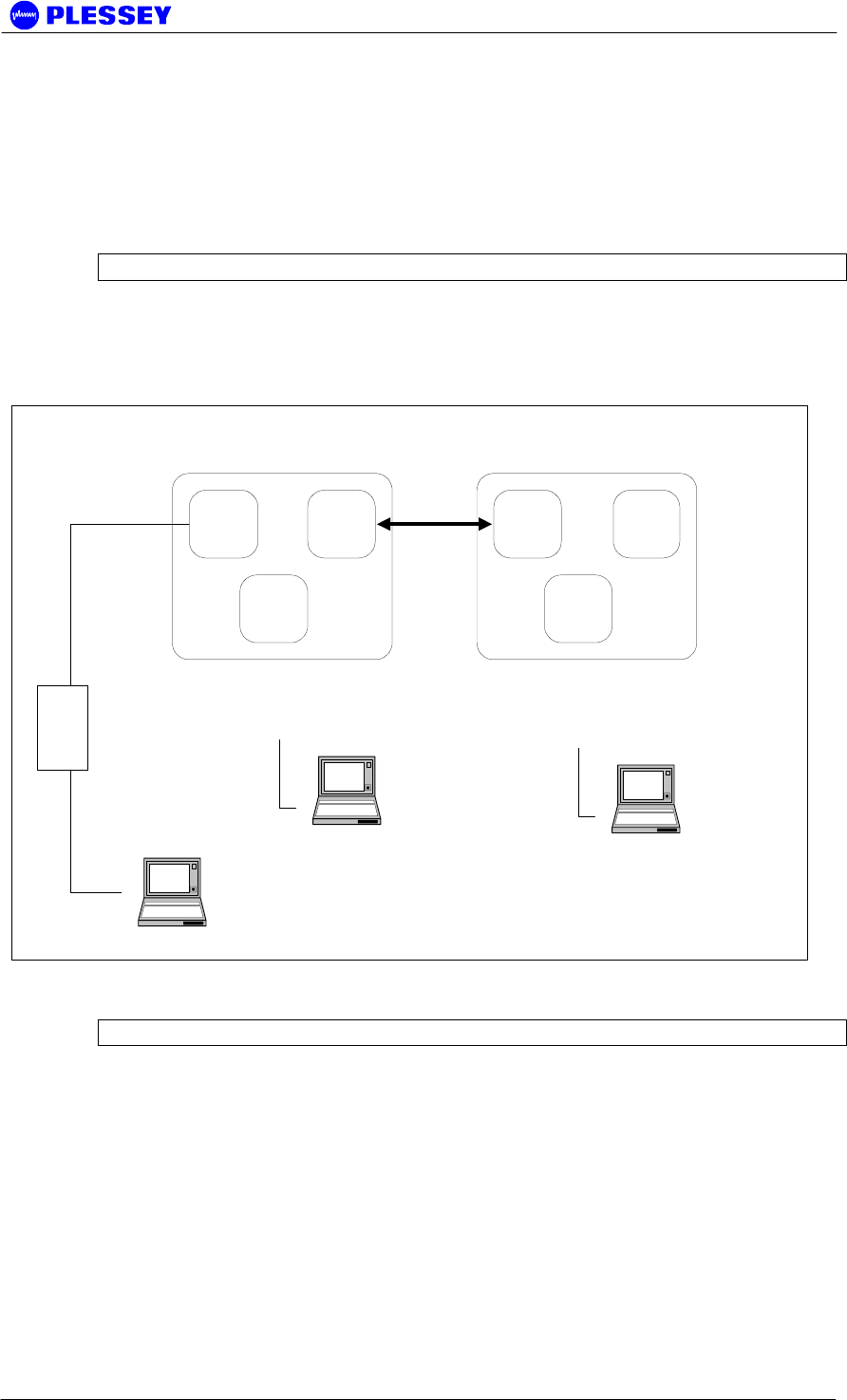
The following diagram shows the default (factory) network IP addresses assigned to
the various network ports on the MDR / Orion System: ROUTING CONFIGURATION
C.1 IP CONFIGURATION OF THE MDR / Orion – ROUTING
CONFIGURATION
10.2.1.2 10.10.9.9
10.13.1.1
10.10.9.10 10.11.1.2
10.12.1.1
Ethernet
10-BaseT
PPP
RS232
PPP
WIRELESS
PPP
RS232
Ethernet
10-BaseT
"NEAR" "FAR"
Laptop computer
Browser/NMS
10.2.1.3
(IP User assigned)
Hub
MDR / Orion - ROUTING CONFIGURATION
Laptop computer
Browser/NMS
10.12.1.2
(IP Auto assigned)
"Server assigned"
Laptop computer
Browser/NMS
10.13.1.2
(IP Auto assigned)
"Server assigned"
To allow pinging of a DIU configured as a "remote unit" i.e. with an IP address of
(10.11.1.2) when the PC has a 10.2.1.3 IP address, 10.2.1.2 default gateway and
netmask 255.255.0.0, create batch files.
Batch file 1 - addroute.bat
route add 10.11.0.0 mask 255.255.0.0 10.2.1.3
Batch file 1 adds a route so that the IP stack on the PC "knows" where to send IP
packets destined for the net 10.11.0.0

MDR2400/5800-SR, Orion2410/5810-SRi and Orion 5825-SR
862-01881 Issue 12c Page 107
If you want to delete the route, use
Batch file 2 - delroute.bat
route delete 10.11.0.0
If you want a screen printout of the routes the PC is using, use the command line
entry:
route print
NOTE
DO NOT ALLOW AN RF LINK TO ESTABLISH BEFORE DOING A PING on the
remote DIU (with 10.11.1.2 as an IP address) - if the RF link was established
before, use the front panel button "position 3" to reset the DIU before
attempting to ping.
MDR2400/5800-SR, Orion2410/5810-SRi and Orion 5825-SR
862-01881 Issue 12c Page 108
C.2 IP CONFIGURATION OF THE MDR / Orion – BRIDGING
CONFIGURATION
The following diagram shows the default (factory) network IP addresses assigned to
the various network ports on the MDR / Orion System: BRIDGING CONFIGURATION.
NOTE For most networks, bridging is the preferred IP configuration.
192.168.1.2 192.168.4.2
192.168.2.2
192.168.4.3 192.168.1.3
192.168.3.3
Ethernet
10-BaseT
PPP
RS232
PPP
WIRELESS
PPP
RS232
Ethernet
10-BaseT
"NEAR" "FAR"
Laptop computer
Browser/NMS
192.168.1.4
(IP User assigned)
Hub
MDR / Orion - BRIDGING CONFIGURATION
Laptop computer
Browser/NMS
192.168.3.2
(IP Auto assigned)
"Server assigned"
Laptop computer
Browser/NMS
192.168.2.3
(IP Auto assigned)
"Server assigned"
NOTE The netmask for all the 192.168.x.x addresses is 255.255.255.0

MDR2400/5800-SR, Orion2410/5810-SRi and Orion 5825-SR
862-01881 Issue 12c Page 109
D Appendix: MDR5800 hardware VERSION 1, 2.x
DIFFERENCES, COMPATIBILITY SUMMARY
Version 1 hardware (Indoor and RF Units) is incompatible with Version 2.x hardware.
The Digital Indoor Unit /RF Unit Twisted Pair Data Interconnection for Version 2
hardware uses 2 twisted pair cables to convey payload and RF Unit control signals
whereas Version 1 hardware uses 4 twisted pair cables.
Notes :
Version 2.x firmware (can be uploaded into the Digital Indoor Unit using the NMS’s
Maintenance option) that can be used in Version 1.x hardware must be obtained from
the product manufacturer. The file is not the same file that is used with Version 2.x
hardware.
Updated RSSI and Power control functionality have been added to Version 2.x
hardware and firmware.
Version 2.x firmware has
1. FTP upload functionality (needs to be activated via the MIB)
2. IP Bridging functionality (half and full duplex – selectable via the MIB).
Appropriate DIU hardware must be used.
3. Band Plan C
4. Refer to the MIB section of this manual and look for the † symbol to see what MIB-
related functionality is in place/activated/planned for Version 2.x + firmware.
5. Functional RF Loopback built-in test feature.
6. Ethernet packet error monitoring and buffer monitoring added to MIB
7. E1 CRC4 payload monitoring added to MIB (only applicable for a single tributary)
8. Digital Indoor Unit PCB hardware revision added to MIB
9. Periodic reporting of RF Link packet errors (adjustable in time, defaulted to 10
minutes) added to MIB.
Version 2.x NMS has
1. Ability to allow the user to connect to the Digital Indoor Unit using PPP (via a serial
cable interface to the DIU’s front panel Element Manager RS232 port) or via
Ethernet (via the front panel RJ45 connector: 10BaseT).
2. Graphical Spectrum Analyzer display
By default, firmware provided for the Digital Indoor Units does not provide a secure
login feature (thereby limiting a user’s ability to ‘set’ MIB variables). Suitably adapted
firmware versions (dependent on hardware version) need to be requested from the
product manufacturer to allow activation of this feature.

MDR2400/5800-SR, Orion2410/5810-SRi and Orion 5825-SR
862-01881 Issue 12c Page 110
MDR / ORION DIGITAL INDOOR UNIT FIRMWARE
UPGRADE NOTICE
MDR Version 2 hardware Digital Indoor Units are identified as having 200+ serial
numbers, RF Units have 250+ serial numbers.
If upgrading Digital Indoor Units to use V2.02+ DIU firmware, upgrade the DIU
firmware on BOTH sides of the RF Link.
Note that firmware upgrades of Version 1 MDR Digital Indoor Unit hardware do not
require setting up of the PCB Issue in the MIB i.e. mdrmteIndoorUnitPCBrevision
element. Upgrade to DIU firmware Version 2+ of Version 1 hardware will NOT give
improved RSSI functionality. This is only achieved with Version 2 hardware or
modified version 1 hardware.
Full Duplex Ethernet Capability on MDR DIUs
As a standard setting for mdrmteIndoorUnitPCBrevision, use MIB selection Issue_2.
HOWEVER, if an appropriate Indoor PCB modification (made at the factory) has been
made to allow Full Duplex Ethernet operation, the Issue_2_Mod_A selection option in
the MIB MUST be used.
Per trib line code selectivity on MDR DIUs
MDR Digital Indoor Units that are modified to allow T1 line codes to be selected
uniquely on a per trib basis are identified by a hardware version number of 2.1AT.
These Digital Indoor Units must only be operated with firmware version 4.09 and
higher. The PCB revision of these units should also be set to 5.
Table 13 indicates the compatibility between different indoor and RF Unit types. The
DIU firmware types required to provide the compatibility between different hardware
types are listed in.
NOTE Different Digital Indoor Unit firmware versions may be required to provide
compatibility between different indoor and RF Unit types.
Table 13 Indoor - RF Unit compatibility matrix.
Hardware Type MDR DIU ORION 10 DIU ORION 25 DIU
MDR2400 RFU
Orion2410i RFU X X X
MDR5800 RFU
Orion5810i RFU X X X
MDR5850 RFU X X
Older versions (up to version 3.08) of the firmware are only suitable for MDR Digital
Indoor Units and are identified by the following filename:
IDU_X_XX.CVF, WHERE THE X_XX IS THE NUMERIC VERSION NUMBER.
Newer firmware versions (version 4 upwards) are identified by the following filename:
abcddeeefghI_x_xx.cvf, where x_xx is the numeric version number of the firmware.
The other fields in the name has the following meaning:
a: M or O = Digital Indoor Unit PCB (MDR or Orion)
b: C=100 X=10 Ethernet to RFU (or - if both are supported)

MDR2400/5800-SR, Orion2410/5810-SRi and Orion 5825-SR
862-01881 Issue 12c Page 111
c: 2=v2 framing 3=v3 framing structure (3 is programmable, 2 is used on MDR)
dd: tt = 04=4 tribs 08=8 tribs E3, T3, etc
eee: 2.4 5.8 if it's specifically limited, not in name if not used
f: T or E for T1/E1 if it's specifically limited, not in name if not used
ghi: Reserved, not in number if not used
Examples:
oc308_4_04.cvf = Orion 100M v3 framing 8 tribs (Normal 8e1)
ox204_4_04.cvf = Orion 10M v2 framing 4 tribs (CCK-compatible 8e1)
mx204_4_09.cvf = MDR type DIU firmware.
MDR2400/5800-SR, Orion2410/5810-SRi and Orion 5825-SR
862-01881 Issue 12c Page 112
E Appendix: FIXED Antennas
The table below identifies the distances where the 1mW/cm2 exposure limits may be
exceeded during continuous transmission using the proposed fixed antennas.
E.1 MDR5800
Manufacturer Type Model Gain
(dBi)
Numeric
gain
Peak
Power
(mW)
Calculated
Distance (m)
Minimum RF
Exposure
Separation
Distance (m)
Gabriel Dish SSP2 52B 29.0 794.3 239.9 1.2 2
Gabriel Flat panel DFPD1-52 23.9 245.5 239.9 0.7 2
MTI Flat panel MT-20004 28.0 631.0 239.9 1.1 2
E.2 Orion5810i
Manufacturer Type Model Gain
(dBi)
Numeric
gain
Peak
Power
(mW)
Calculated
Distance (m)
Minimum RF
Exposure
Separation
Distance (m)
Gabriel Dish SSP2 52B 29.0 794.3 239.9 1.2 2
E.3 Orion5850
Manufacturer Type Model Gain
(dBi)
Numeric
gain
Peak
Power
(mW)
Calculated
Distance (m)
Minimum RF
Exposure
Separation
Distance (m)
Gabriel Dish SSP2 52B 29.0 794.3 239.9 1.2 2
MTI Flat panel MT-20004 28.0 631.0 239.9 1.1 2
E.4 MDR2400 and Orion2410i
Manufacturer Type Model Gain
(dBi)
Numeric
gain
Peak
Power
(mW)
Calculated
Distance (m)
Minimum RF
Exposure
Separation
Distance (m)
Gabriel Parabolic SSG4-23 26.7 467.7 63 0.5 2
WARNING: It is the responsibility of the professional installer to ensure that when
using the outdoor antenna kits in the United States (or where FCC rules apply), only
these antenna configurations shown in the table above are used. The use of any
antenna other than those listed is expressly forbidden in accordance to FCC rules
CFR47 part 15.204.
FCC Radiation Exposure Statement
This equipment complies with FCC radiation exposure limits set forth for an
uncontrolled environment when installed as directed.
This equipment should be installed and operated with fix-mounted antennas that are
installed with a minimum separation distance of 2 meters (6.6 ft) or more from all
persons during normal operation to satisfy RF exposure requirements.

MDR2400/5800-SR, Orion2410/5810-SRi and Orion 5825-SR
862-01881 Issue 12c Page 113
F Appendix: Useful web links
The URL http://www.plesseyinc.com/ provides information on current products
as well as some FAQ.
For any other questions, the latest firmware or software, contact your local
distributor, customer support on the above web site or customer support at
mdrsupport@tellumat.com.

MDR2400/5800-SR, Orion2410/5810-SRi and Orion 5825-SR
862-01881 Issue 12c Page 114
G Appendix: MDR / Orion SCALABLE 1-to-4/8 E/T1 / 10 Base-
T Ethernet functionality
Depending on the radio model and RFU configuration, the MDR / Orion radio can
simultaneously support 1 to 8 E1 or T1 tributary channels, with the balance of the
available user BW made up by Ethernet packet data, up to a maximum aggregate
Ethernet throughput no greater than 9.5 Mbps (Combined up- and downstream
throughput). The unidirectional Ethernet throughput of the radios is limited to a
maximum of 8 Mbps, which decreases as more tributary channels are activated.

MDR2400/5800-SR, Orion2410/5810-SRi and Orion 5825-SR
862-01881 Issue 12c Page 115
H Appendix: MDR / Orion FTP Firmware Upload
Firmware can be uploaded to MDR and Orion DIUs using FTP uploads as well as by
using the "CVF Loader" or NMS software, available on the software CD or from the
distributor.
Note the following:
Username : anonymous
Password : guest
The relevant MIB info is in the "mdrmteConfiguration" GROUP
1.3.6.1.4.1.1316.1.1.1.2.5 mdrmteFirmware
1.3.6.1.4.1.1316.1.1.1.2.5.1 mdrmteFTPServerStatus
1.3.6.1.4.1.1316.1.1.1.2.5.2 mdrmteFlashNewFirmware
By Default for mdrmteFTPServerStatus : the Digital Indoor Unit FTP server is active
By Default for mdrmteFlashNewFirmware : the upgrade is immediate (it can also be
timed)
We recommend that the user ALWAYS verify that the new version has indeed been
uploaded and is being used by the DIU. In this case one checks the following
element:
1.3.6.1.4.1.1316.1.1.1.2.4.3 mdrmteIUFirmwareVersion
This OID (object ID) is part of:
1.3.6.1.4.1.1316.1.1.1.2.4 mdrmteGeneral, part of the "mdrmteConfiguration" GROUP
When updating the Digital Indoor Unit firmware by means of FTP, please note that the
choice of IP address is very important. You must always choose the IP address of the
interface "closest" to you. In other words if you are using Ethernet to connect, then use
the IP address of the Ethernet Interface.
NOTE If you are updating the firmware on the remote unit, use the IP address of the
"overhead" PPP link - NOT the Ethernet interface of the remote unit. For example use
192.168.4.3 when uploading to the far side and using the bridging configuration. If by
mistake you use the wrong address, you will create a "half-established" FTP session,
and NO FURTHER SESSIONS will be permitted until the session times out after some
minutes.

MDR2400/5800-SR, Orion2410/5810-SRi and Orion 5825-SR
862-01881 Issue 12c Page 116
Setup for Full Duplex mode on the MDR: Max Transfer Rate
Follow the steps outlined below to setup the MDR radio in Full Duplex mode:
• Upload the radio Firmware by following the aforementioned procedure. Full
duplex Ethernet operation is supported from version 2 of the firmware.
• Setup default configuration of the radio to the required configuration. Refer to
Section 2.3.4 for a description of the different default configurations.
• Ensure that the PCB revision of the DIU is issue_2_mod_a(3) by reading the
following MIB element: 1.3.6.1.4.1.1316.1.1.1.2.4.15
mdrmteIndoorUnitPCBrevision. If the PCB revision is issue_2(2) the radio
hardware does not support Full Duplex Ethernet mode.
• Disable all tributary channels to make the maximum user bandwidth available for
Ethernet traffic.
• Enable Full Duplex mode via the MIB using element: 1.3.6.1.4.1.1316.1.1.1.4.16
mdrmteEthernetFullDuplex.
• Set the data rate to T1 if required using MIB element: 1.3.6.1.4.1.1316.1.1.1.2.1.1
mdrmteDataRate.

MDR2400/5800-SR, Orion2410/5810-SRi and Orion 5825-SR
862-01881 Issue 12c Page 117
I Appendix: Getting started guide
I.1 Checklist for Bench Testing (without a PC)
You will need the following: Chec
k
Additional Information
1 1 MDR / Orion User Manual
(Issue 11)
2 2 Digital Indoor Units
3 2 RF Units 1 low and 1 high band - see L/H
stamp near serial number
4 1 or 2 Power supplies User Manual par. 4.2.3 and 8.4
5 2 Digital Indoor Unit power
cables
User Manual par. 4.2.3
6 2 Indoor to RF Unit power
cables
Specifications - User Manual par.
8.5.10
7 2 Indoor to Outdoor RJ45 Data
cables
Connections - User Manual par.
4.4.1
8 N-type male to N-type male (6
GHz) RF cable
Type and connection - User
Manual par. 4.3.1
9 60 - 90 dB of N-type attenuators Note Max input is -30 dBm, default
output power is +24 dBm
10 2.5 mm Allen Key Required to open the connector lid
on the RF Unit.
11 3 mm terminal screwdriver Required to connect the power
cables
Recommended items:
12 T1 or E1 BER Tester
13 T1/E1 Payload cable User Manual par. 4.2.4, 4.2.5,
4.2.6
14 Payload Loopback Connector User Manual par. 4.2.4, 4.2.5,
4.2.6
You will need to know:
15 How to use the reset button:
When you press and hold down the reset button on the front panel with a suitable
tool,the 3 LEDs on the front panel will change state depending on the duration that
the button is held down for:
Count the number of state changes and let go of the reset button when the desired
count is reached: It starts off with one green LED in the right most position,
"moving" to the left:
Numb
er
Left
(System)
Middle(Payloa
d)
Right (RF
Link)
1 off off Green

MDR2400/5800-SR, Orion2410/5810-SRi and Orion 5825-SR
862-01881 Issue 12c Page 118
2 off Green off
3 Green off off
Then an Orange LED "moving" from right to left (for 4-6), then Red, then Green
again etc.
NOTE If you accidentally overshoot, keep on holding the reset button until all the LEDs
eventually go off. Then release the button and try again.
See User Manual - par. 2.3.4 for more detail.
16 How to interpret the status of
the LEDs:
Interpreting Rear Panel LED (Front Panel on Orion DIU)
DIU/RFU Link LED - OFF: No communication between Indoor and RF Units
Check cables between Digital Indoor Unit and RF Unit
Interpreting Front Panel LEDs
Continually Lit LEDs
LED COLOR I.2 Interpretation I.3 Action
System RED There is a problem with the
communication to the RF Unit
Check cables between
Digital Indoor Unit and
RF Unit
RF Link RED Continually running bit errors
on tributaries
If System LEDs are
green then check RF
Units
Payload RED The is no Payload signal
present (LOS) on one or more
tributaries
Check connections to
the BER Tester
System ORANGE There is a problem with the
communication to the RF Unit
Check cables between
Digital Indoor Unit and
RF Unit
RF Link ORANGE FEC is correcting errors - no
problem
No problem unless the
LED stays orange
Payload ORANGE The incoming payload signal
is AIS
Check BER tester
Flashing/Blinking LEDs
A blinking LED indicates that a particular error condition from the table above
(same colour coding) occurred at some time in the past.
You can clear this memory of past errors by applying a "1 LED"-reset.
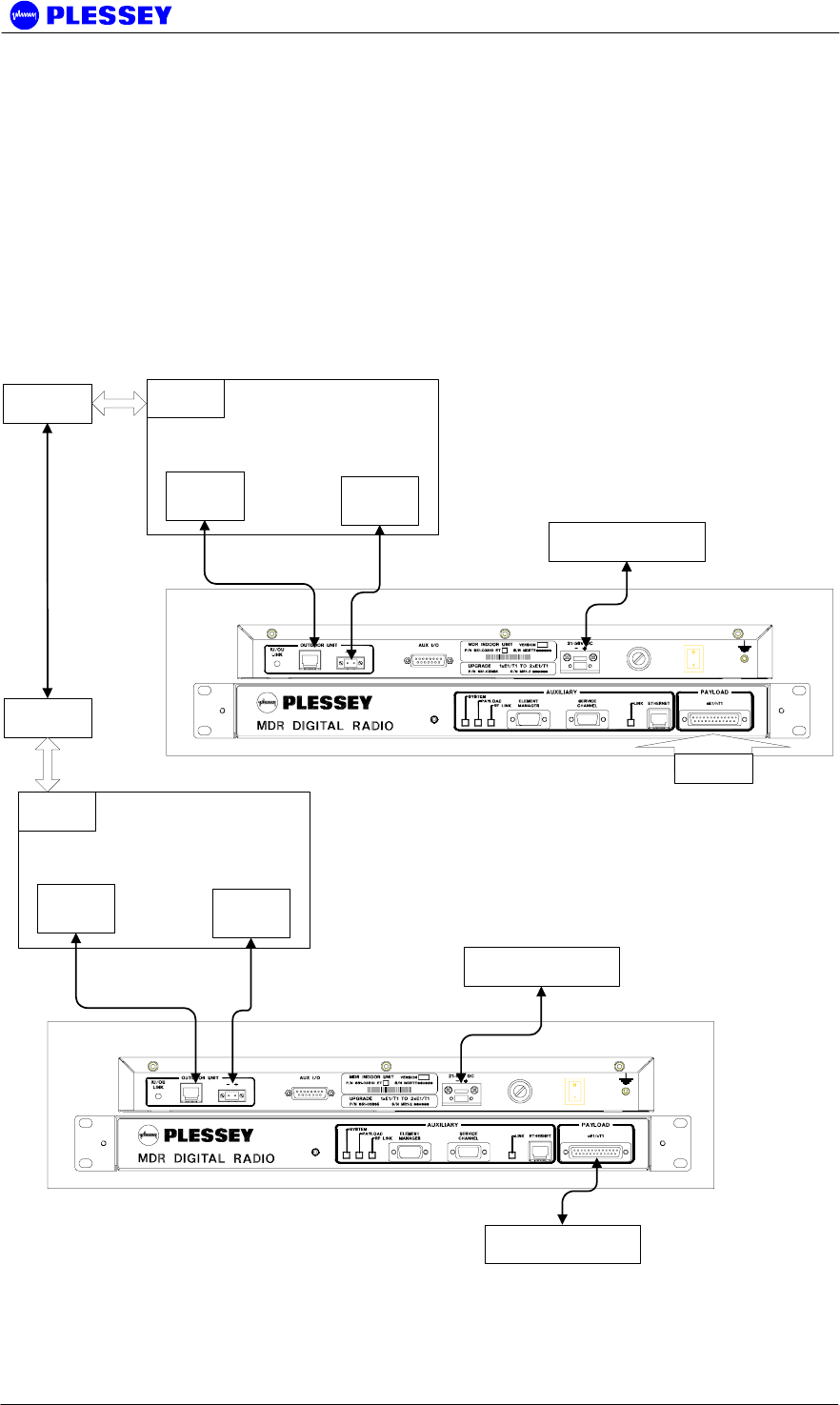
MDR2400/5800-SR, Orion2410/5810-SRi and Orion 5825-SR
862-01881 Issue 12c Page 119
I.4 One Page Set-up for T1/E1 Bench Test (without a PC)
1. PREPARATION: Complete the attached check list
This section applies to the MDR and Orion radio series with the only
difference being the location of the interface connectors on the MDR and
Orion DIUs.
Complete the attached checklist (above section) to ensure that you have the
required equipment and information to continue.
Do not continue until you have read the checklist in the above section!
2. CONNECT AS SHOWN, THEN SWITCH POWER ON
Far Side Indoor Unit
Outdoor Unit
Near Side Indoor Unit
DC Power Supply
BER Tester
Power
Data
RF
Attenuator
DC Power Supply
Outdoor Unit
Power
Data
RF
Attenuator
Loopback
Connector

MDR2400/5800-SR, Orion2410/5810-SRi and Orion 5825-SR
862-01881 Issue 12c Page 120
3. CONFIGURE USING THE RESET BUTTON
Be sure that you know how to use the reset button before continuing!
See note "How to use the reset button" on the checklist, above section.
Configure your payload type to T1 or E1:
For E1: Do a 12-reset on both Digital Indoor Units
For T1: Do a 13-reset on both Digital Indoor Units
Configure Near and Far side Digital Indoor Units:
For Near: Do an 8-reset on the Digital Indoor Unit you would like as the
"Near" side unit
Note that this clears all stored parameters to factory defaults
For Far: Do a 7-reset on the Digital Indoor Unit you would like as the
"Far" side unit
Note that this clears all stored parameters to factory defaults
4. CLEAR ERRORS
Apply a 1-reset to Clear the Historical errors on the Front Panel LEDs
See note "Interpreting LED Status" on the checklist
Apply a 2-reset to Clear the Event Log in the Digital Indoor Unit
This is required if you wish to view the Event Log using a PC.
Reset your BER Tester.
5. MONITOR STATUS
Be sure that you know how to interpret the status of the LEDs before continuing!
See note "Interpreting LED Status" on the checklist
If all is well, then:
BER Tester should run with no errors
All 3 Front Panel LEDs should be green.
(The RF Link LED may flash orange without the need to worry.)
If you have not connected a BER Tester, then the Payload LED will be Red,
indicating LOS i.e. no payload signal.
NOTE Make sure to deactivate all unused tribs to ensure that the Payload LED stays
GREEN for the tribs used. That is: if only two tribs are used, but all four are active, a
RED Payload LED will be indicated as the two unused tribs have LOS. Deactivating
the two unused tribs through the NMS / GUI, will result in the Payload LED only
indicating information for two active tribs – i.e. are there a valid signals on the two
tribs, regardless of the two other, unused tribs.

MDR2400/5800-SR, Orion2410/5810-SRi and Orion 5825-SR
862-01881 Issue 12c Page 121
J APPENDIX: 1+1 PROTECTION SYSTEM OPERATION
J.1 Introduction
J.1.1 System Description
When a single radio link is used to convey user data, any number of unexpected
events may cause the link to fail resulting in user data being lost. This would require
immediate corrective actions from the network operator responsible for maintaining the
radio link. Since such a failure may occur at any time and possibly at a remote
location, corrective actions may be very costly, both in terms of downtime and human
resources. Common reasons for radio links to fail are:
• Signal fading on the radio link
• The presence of strong in-band interference
• Equipment failure
One possible solution to this problem is to install a second redundant radio link that
can automatically take over the function of the primary radio link. This not only
reduces the downtime of the link, but also provides the network operator with the
opportunity to repair the faulty link at a convenient time.
This document describes the one-plus-one redundancy system that can be used with
the radio products of Plessey BBW. Radio systems that are currently supported by the
system are:
• MDR2400-SR
• MDR5800-SR
• Orion 2410-SRi
• Orion 5810-SRi
• Orion 5825-SR
The remainder of this document is aimed at giving a detailed technical description of
the redundancy system and the installation thereof.
J.2 Technical Description
J.2.1 System Overview
The functionality required to establish a protected radio link is already built into the
MDR- and Orion-type Software Radios. This implies that the user can set up a
protected radio link by interconnecting the equipment for two parallel radio links
through a 1U protection panel and a dedicated communications cable.
Each Digital Indoor Unit in a protected radio system continuously monitors the status
of the radio link it uses, as well as the radio link provided through the redundant
system running in parallel. Digital Indoor Units forming part of a redundant link at each
end of the radio link share status information through a cable connecting the two
Auxiliary ports of the Digital Indoor Units.

MDR2400/5800-SR, Orion2410/5810-SRi and Orion 5825-SR
862-01881 Issue 12c Page 122
Only the tributary payload data channels are protected by the redundant link i.e. there
is no protection for Ethernet data. Tributary payload data is split and combined
between links through a 1U protection panel that connects to the user network
equipment as well as the two Digital Indoor Units used at each end of the redundant
link. Although both radio links are functioning continuously, only one of the Digital
Indoor Units is actively driving the tributary channels of the user network at any given
time.
Each Digital Indoor Unit continuously monitors the level of the Packet Error Ratio
(PER) for the radio link on which it is receiving user data. When the PER exceeds a
predefined ratio of 10 consecutive seconds, the Digital Indoor Unit driving the tributary
channels of the user network will signal the redundant Digital Indoor Unit to take over
processing the data it receives over the radio link.
The value of the PER threshold is configurable and can be changed through the Orion
NMS if required. The default value is set at 30%.
There is no notion of a primary and secondary link in this redundancy system. The
first link to be configured successfully will start driving the tributary payload channels.
Switch over will only take place when the aforementioned condition occurs. In the
event where the link to which the data was switched over fails at a later stage, the
system will attempt to switch the data back to the original link.
NOTE 1 A situation can arise where the up- and downstream user tributary data is
carried by separate radio links, i.e. link A carries the upstream data, and link B carries
the downstream data.
NOTE 2 Due to the architecture of the redundancy system, the process of switching
over from one link to another is not hitless and user tributary data will be lost for a few
seconds (< 10)
J.2.2 System Configuration
The block diagram in Figure 10 illustrates a typical redundancy system configuration.
Note that this system is managed over an Ethernet LAN, where the two local Digital
Indoor Units are connected to the LAN using a hub. It is important to note that the IP
addresses for each Digital Indoor Unit should be unique. It is however possible to
configure each link in the redundant system separately through the Element-Manager
port of each local Digital Indoor Unit, in which case it is not necessary to assign unique
IP addresses to the Digital Indoor Units.
The block diagram in Figure 10 also clearly illustrates the following important
interfaces:
• DIU A to DIU B connection through the respective Auxiliary ports of the four
Digital Indoor Units
• The Protection Panel interfaces on each side of the link that combines and splits
the tributary payload channels between the two radio links
• The single user network interfaces provided by the Protection Panel
• The two radio links that provide the redundancy required for user data
protection
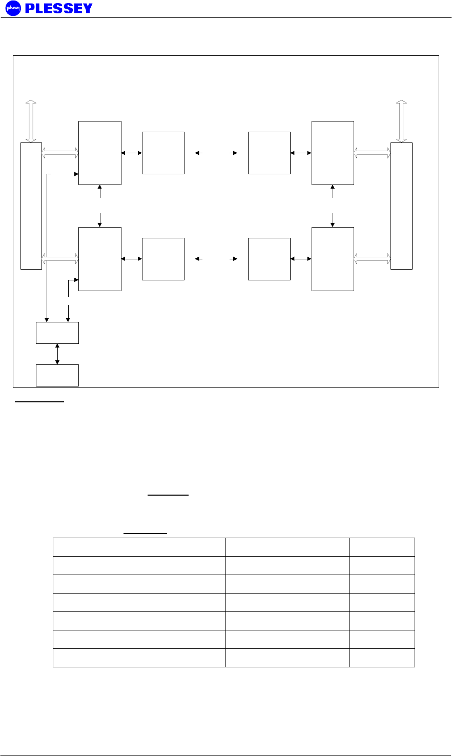
MDR2400/5800-SR, Orion2410/5810-SRi and Orion 5825-SR
862-01881 Issue 12c Page 123
IDU 1 A
IDU 1 B
IDU 2 A
IDU 2 B
ODU ODU
ODU ODU
RF Link A
RF Link B
HUB
Ethernet
Tributries
AUX Port
Cross Connect
Ethernet
Network Port IP Addr
192.168.1.2
Network Port IP Addr
192.168.1.4
Network Port IP Addr
192.168.1.3
Network Port IP Addr
192.168.1.5
Config PC
Tributries
AUX Port
Cross Connect
One-Plus-One Redundancy System
Protection Panel
Splitter/Combiner
Protection Panel
Splitter/Combiner
Figure 10: Block diagram of a typical redundancy protected system where the radio links
are managed through an Ethernet network.
J.2.2.1 1U Protection Panel
There are two types of protection panels: a four and an eight tributary channel panel.
They operate in the same way and perform the signal splitting and combination
functions for the tributary channels taking part in the redundancy protected radio
system. Note from Table 14: Protection Kit connector interfaces. that the Protection
Kit is currently only provided in 110-ohm as a compromise to make provision for E1
and T1 mode.
Table 14: Protection Kit connector interfaces.
Description Connector Impedance
Orion Protection Panel
Payload Network Interface 2xDB-25 or 8xRJ-48 110 ohm
Digital Indoor Unit Interface 2x2xDB-25 110 ohm
Orion Protection Panel
Payload Network Interface DB-25 or 4xRJ-48 110 ohm
Digital Indoor Unit Interface 2xDB-25 110 ohm
The cables required to connect the Patch Panel to the two Digital Indoor Units are
provided with the Patch Panel. The DB-25 pinouts used for each DB-25 connector on
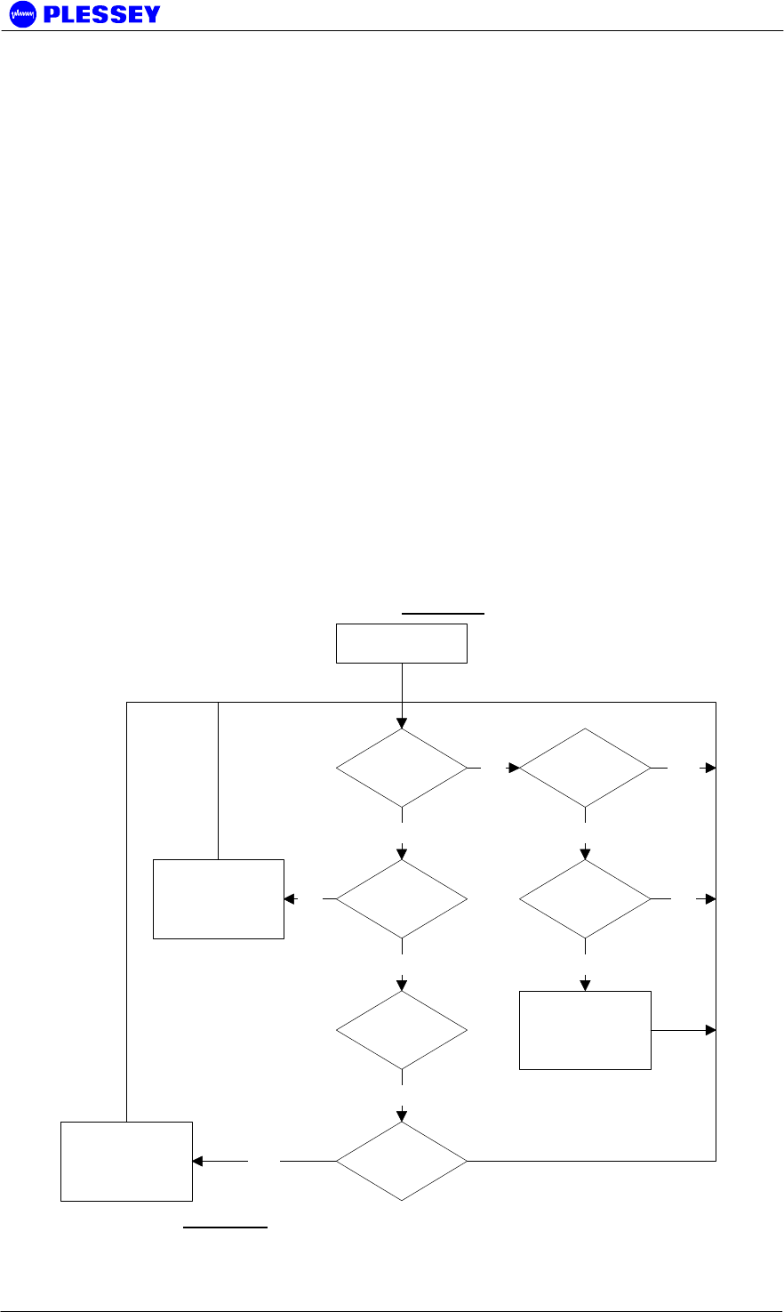
MDR2400/5800-SR, Orion2410/5810-SRi and Orion 5825-SR
862-01881 Issue 12c Page 124
the patch panel are exactly the same as that of the MDR and Orion Digital Indoor Units
respectively.
J.2.2.2 Auxiliary port communication
The two Digital Indoor Units on each side of the radio link share status information
through the two relay outputs and OPTO inputs on the Auxiliary (AUX) port of each
Digital Indoor Unit. Information shared by each of these:
• Indication if the Digital Indoor Unit is currently driving the tributary channels on
the user network
• The current Frame Lock status detected by the Digital Indoor Unit for the radio
link it is using
J.3 System functional description
Each Digital Indoor Unit taking part in a protected radio link continuously monitors the
PER of the radio link it is receiving tributary data over. If the PER for the link increases
above the Sever Error Margin for more than 10 consecutive seconds, the Digital
Indoor Unit will request the second Digital Indoor Unit to take over the driving of the
tributary channels if the second Digital Indoor Unit sees a frame lock.
Once the second Digital Indoor Unit has started driving the tributary channels, the first
Digital Indoor Unit becomes the redundant link.
The flow diagram for the algorithm that governs the protection switch-over process in
each Digital Indoor Unit is illustrated in Figure 11.
Is IU driving the
Tribs
PER >
Threshold
YES
YES
Timer >= 10sec
Redundant IU
has frame lock
YES
Start Driving Tribs
& Signal
Redundant IU
Is Redundant
IU driving Tribs
IU has frame
lock
Reset Timer
Stop Driving Tribs
& Signal
Redundant IU
NO
NO
YES
YES
NO NO
YES
Reset
Figure 11: Redundant system switch-over algorithm.
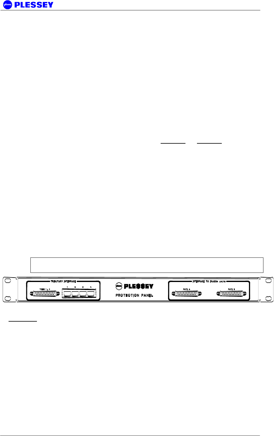
MDR2400/5800-SR, Orion2410/5810-SRi and Orion 5825-SR
862-01881 Issue 12c Page 125
J.4 Installation
J.4.1 Hardware Installation
The following list of equipment is required to set up a protected radio link:
• Four MDR / Orion Digital Indoor Units
• Four MDR / Orion RF Units
• Two MDR / Orion Protection Kit 1U panels (Supplied with protection kit)
• Four / Eight DIU interface loom cables (Supplied with protection kit)
• Tributary channel interface cables to connect to the user network
• Two DIU auxiliary communications cables (Supplied with protection kit)
• Standard tools and cabling required to set up a MDR / Orion radio link
Illustrations of the Protection Kits can be seen in Figure 12and Figure 13. Note from
the drawings that the Orion Protection Kit offers the ability to protect eight E1/T1
tributary channels. Thus, the latter could be used with either the MDR or Orion radios.
Follow the steps below at each site to interconnect and set up the protected radio
systems:
• Install each DIU-RFU system as described in the MDR / Orion User Manual
• Install the four / eight tributary channel Protection Kit panel in the rack mount
• Connect tributary paths A and B on the Protection Kit panel to the two installed
Digital Indoor Units using the provided DB-25 interface cables
• Link the two Digital Indoor Unit auxiliary ports of the Digital Indoor Units through
the DIU auxiliary communications cable
• Switch on the two units and configure the radios as explained in Section J.4.2
• Connect the tributary interface of the Protection Kit panel to the user network
through the preferred interface (DB-25 / RJ48)
NOTE Be sure to acquire the correction protection kit that matches the Digital Indoor
Unit type you intend to use.
Figure 12: MDR Protection Kit front panel.
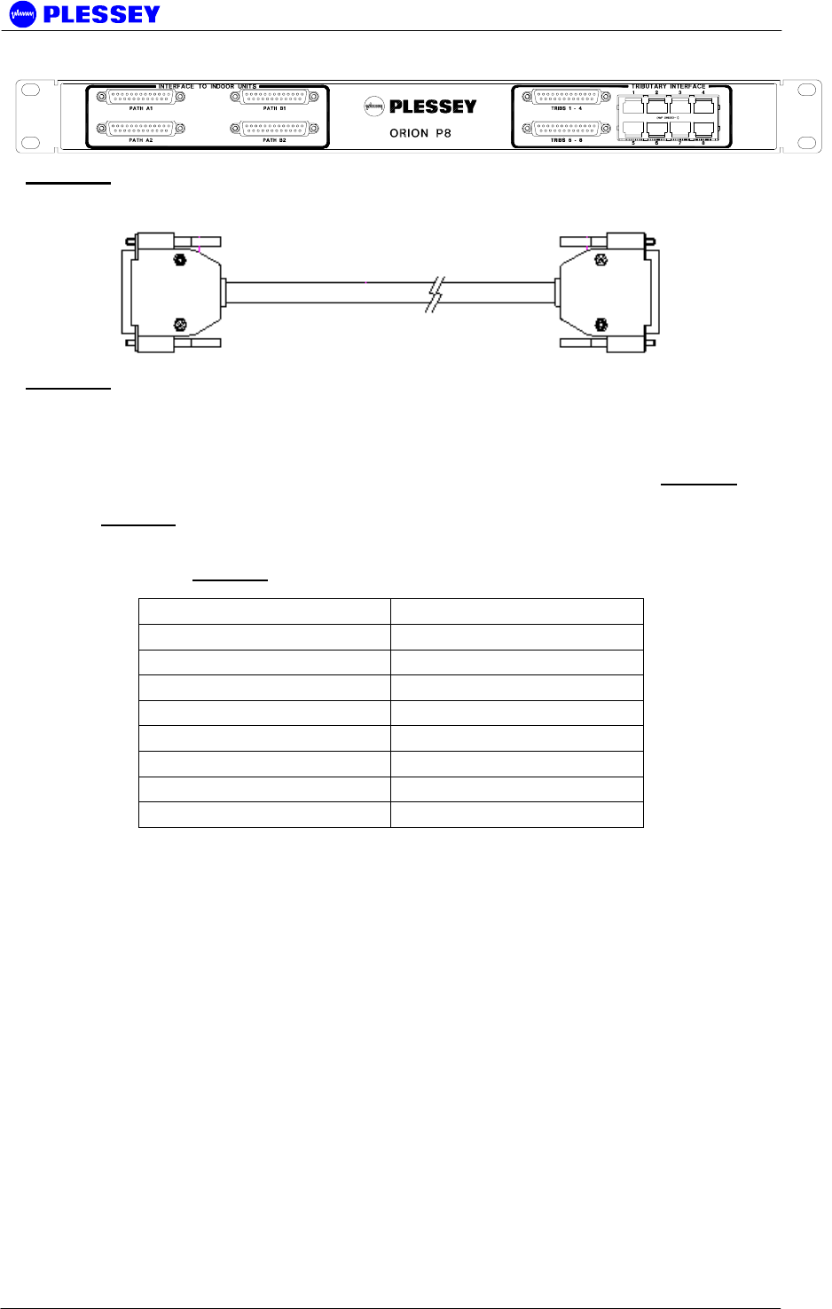
MDR2400/5800-SR, Orion2410/5810-SRi and Orion 5825-SR
862-01881 Issue 12c Page 126
Figure 13: Orion Protection Kit front panel.
Figure 14: Tributary channel interface cable used to connect Protection Kit Paths A & B
to the two Digital Indoor Units.
DIU auxiliary communications cables are supplied with the Protection Kit and are used
to connect the auxiliary ports of the two Digital Indoor Units according to Table 15.
The system diagram when using the two radio pairs in bridging mode is shown in
Figure 10.
Table 15: Auxiliary Port cross connection.
J.4.2 Radio Software Configuration
Two MIB elements are used to configure the radios taking part in the protected radio
link. These MIB elements can be set using any SNMP element manager application,
or through the Orion NMS application. Please refer to the following user manuals for
details on using the above applications:
• MDR / Orion – SR user manual
• Orion NMS HTML user manual
• 3rd party user manual (If a 3rd party SNMP element manager / MIB browser is
used.
Set the following MIB element in all IDUs taking part in the protected radio link to 1
(Yes). mdrmteOnePlusOne (OID: 1.3.6.1.4.1.1316.1.1.1.2.4.17, Parent:
mdrmteGeneral)
Radio 1A Pin No Radio 1B Pin No
1 12
2 13
8 14
9 15
12 1
13 2
14 8
15 9

MDR2400/5800-SR, Orion2410/5810-SRi and Orion 5825-SR
862-01881 Issue 12c Page 127
The MIB element controlling the switch-over threshold, mdrmteSevereErrorMargin
(OID: 1.3.6.1.4.1.1316.1.1.1.2.2.18, Parent: mdrmteRFLinkConf), is set to 30% by
default. This value is a percentage and represents the switch-over threshold for the
Packet Error Ratio (PER). When the PER exceeds 30%, the switch-over will occur.
The value of this MIB element can be adjusted to meet the exact user requirements. It
is advisable to set the switch-over threshold on all Digital Indoor Units to the same
value.
J.5 System Verification
Since most of the functionality of the protected system is hidden from the user, it may
be difficult to monitor the status at times. It can however be determined by monitoring
the MIB elements listed below.
The status of the protected link can also be monitored through the Orion NMS. Please
refer to the Orion NMS user manual for more information on this option.
• Name: mdrmteOnePlusOne – shows if the protected mode is active (OID:
1.3.6.1.4.1.1316.1.1.1.2.4.17, Parent: mdrmteGeneral)
• Name: mdrmtePayloadDrive – shows if the Digital Indoor Unit is driving the
tributary channels of the user network (OID: 1.3.6.1.4.1.1316.1.1.1.3.1.5,
Parent: mdrmteInfo)
• Name: mdrmteLock – shows if frame lock is present (OID:
1.3.6.1.4.1.1316.1.1.1.3.1.6, Parent: mdrmteInfo)
• Name: mdrmtePeerPayloadDrive – shows if the Auxiliary port connected Digital
Indoor Unit (Peer) is driving the tributary channels. This element is the inverse
(opposite) of mdrmtePayloadDrive (OID: 1.3.6.1.4.1.1316.1.1.1.3.1.7, Parent:
mdrmteInfo)
• Name: mdrmtePeerLock - shows if the Auxiliary port connected Digital Indoor
Unit (Peer) has frame lock (OID: 1.3.6.1.4.1.1316.1.1.1.3.1.8, Parent:
mdrmteInfo)
• Name: mdrmteSevereErrorMargin – the threshold percentage value for link
unavailable to switch over (OID: 1.3.6.1.4.1.1316.1.1.1.2.2.18, Parent:
mdrmteRFLinkConf)
• Name: mdrmteAveragePER – average Packet Error Ratio (OID:
1.3.6.1.4.1.1316.1.1.1.1.2.15, Parent: mdrmteRFLinkPerf)
• Name: mdrmteCurrentPER – real time Packet Error Ratio. For example a PER
of 1e-1 (10%) corresponds to a SevereErrorMargin value of 10. The Current
PER has to exceed the Severe Error Margin for 10 seconds continuously for the
link to become unavailable and switch over to its peer Digital Indoor Unit. (OID:
1.3.6.1.4.1.1316.1.1.1.1.2.3, Parent: mdrmteRFLinkPerf)
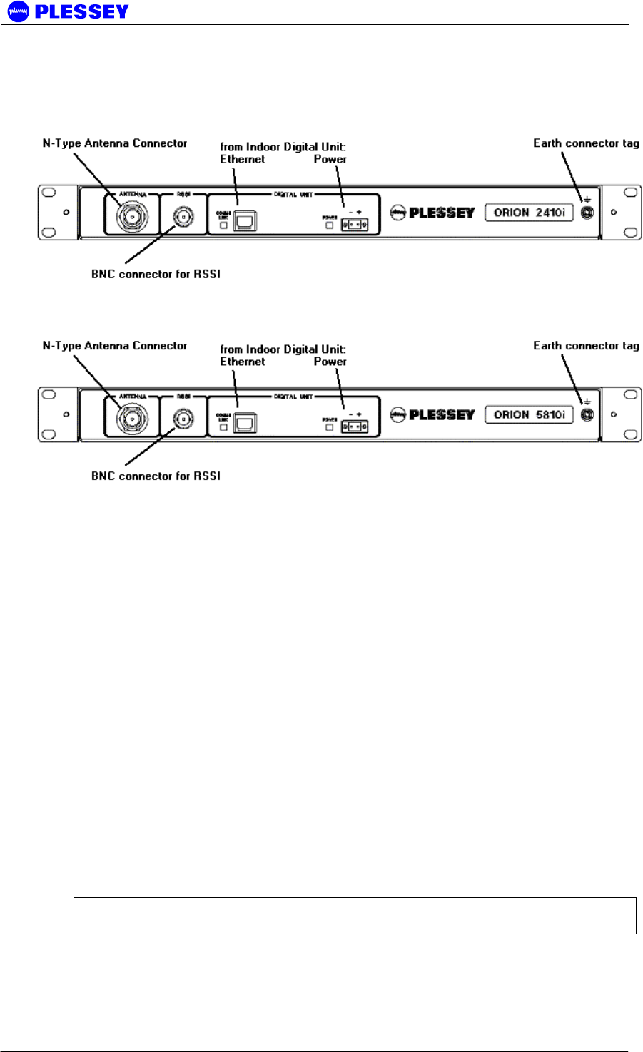
MDR2400/5800-SR, Orion2410/5810-SRi and Orion 5825-SR
862-01881 Issue 12c Page 128
K APPENDIX: Indoor RF Units Orion2410i, Orion5810i
K.1 Description
The Indoor RF Units are functionally similar to the MDR2400 and MDR5800 RF Units
referred to in the body of this manual. All connections and functional indicators are on
the front panel.
Combinations:
Orion2410-SRi = Orion10 (Digital Indoor Unit) + Orion2410i (Indoor RFU)
Orion5810-SRi = Orion10 (Digital Indoor Unit) + Orion5810i (Indoor RFU)
K.2 Steps to install the Indoor RF Unit:
1. Install the Indoor RF Unit similar to description in 4.2.2 not forgetting earthing.
2. Install the system antenna with reference to Section 5. The RSSI BNC connector
is on the front panel.
3. Connect the RF cable or wave guide outer conductor to the pole lightning earth
electrically before it enters the equipment shelter.
4. Connect the type-N RF output connector to the system antenna through an inline
lightning protection unit in areas with lightning activity.
5. Cover the connectors using an ultra violet protective, self-vulcanising tape.
CAUTION – ENSURE THAT THE POLE IS EARTHED FOR LIGHTNING
PROTECTION.

MDR2400/5800-SR, Orion2410/5810-SRi and Orion 5825-SR
862-01881 Issue 12c Page 129
K.3 RF Connection
1. The RF port is an N-type female connector on the front panel.
2. The N-Type connector is used to connect to the antenna, typically using coaxial
transmission line or flexible wave guide via a launch/N-type adaptor.
3. Elliptical wave guide is recommended for longer feeder runs to minimize losses.
4. Also refer to 4.3.1.
K.4 Interconnection Cable Installation
Refer to 4.4 and follow the steps to install the interconnection cables between Indoor
(Digital) Unit and Indoor (RF) Unit. All connections to the Indoor (Digital) Unit are on
the front panel.

MDR2400/5800-SR, Orion2410/5810-SRi and Orion 5825-SR
862-01881 Issue 12c Page 130
Index
A
Add Modem Windows 2000 and XP · 80
auxiliary port · 18, 34
C
cables
IU to OU
connections · 37
IU to OU (RJ45 + power)
cable type · 10, 56
recommended · 56
RF · 36
commissioning · See installation
configuration button · See reset button
connectors
location on IU · 18
customer support · See web links
D
dial-up networking
add
Windows 95/98 · 78
Windows NT · 71, 80
E
element manager
dial-up connection · See modem
PPP RS232 connection · See modem
F
firmware
compatibility · 109
upload
ftp · 115
fuse · 23
G
getting started · 117
I
installation
before radio installation · 29
commissioning record · 44
outdoor unit mechanical · 36
recommended procedure · 29
L
LED reset · See reset button
LEDs
interpreting on front panel · 19
M
modem
add
Windows 95/98 · 76
Windows NT · 66
modulation
different types
MDR2400 · 51
MDR5800 · 51
Orion 5850 · 16
O
outdoor unit
connection to IU · See cables, IU to OU (RJ45
+ power)
P
payload (T1/E1)
BNC · 34
DB25 · 33
location · 18
RJ45 · 34
power
IU DC connector · 23, 32
IU DC requirement · 50

MDR2400/5800-SR, Orion2410/5810-SRi and Orion 5825-SR
862-01881 Issue 12c Page 131
R
reset button · 19
W
web links · 113
www · See web links