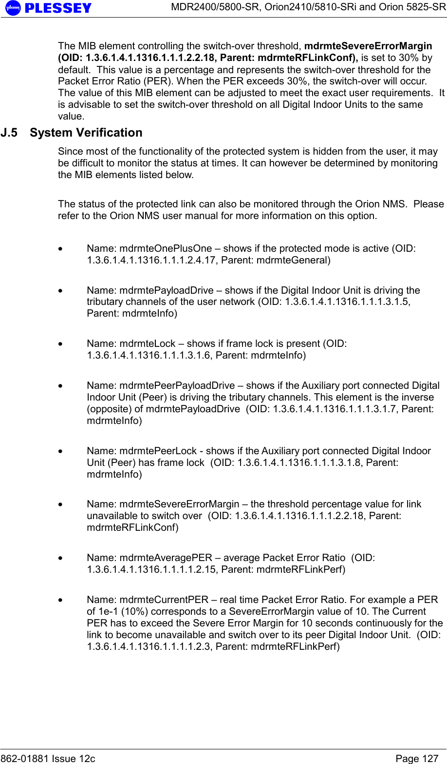
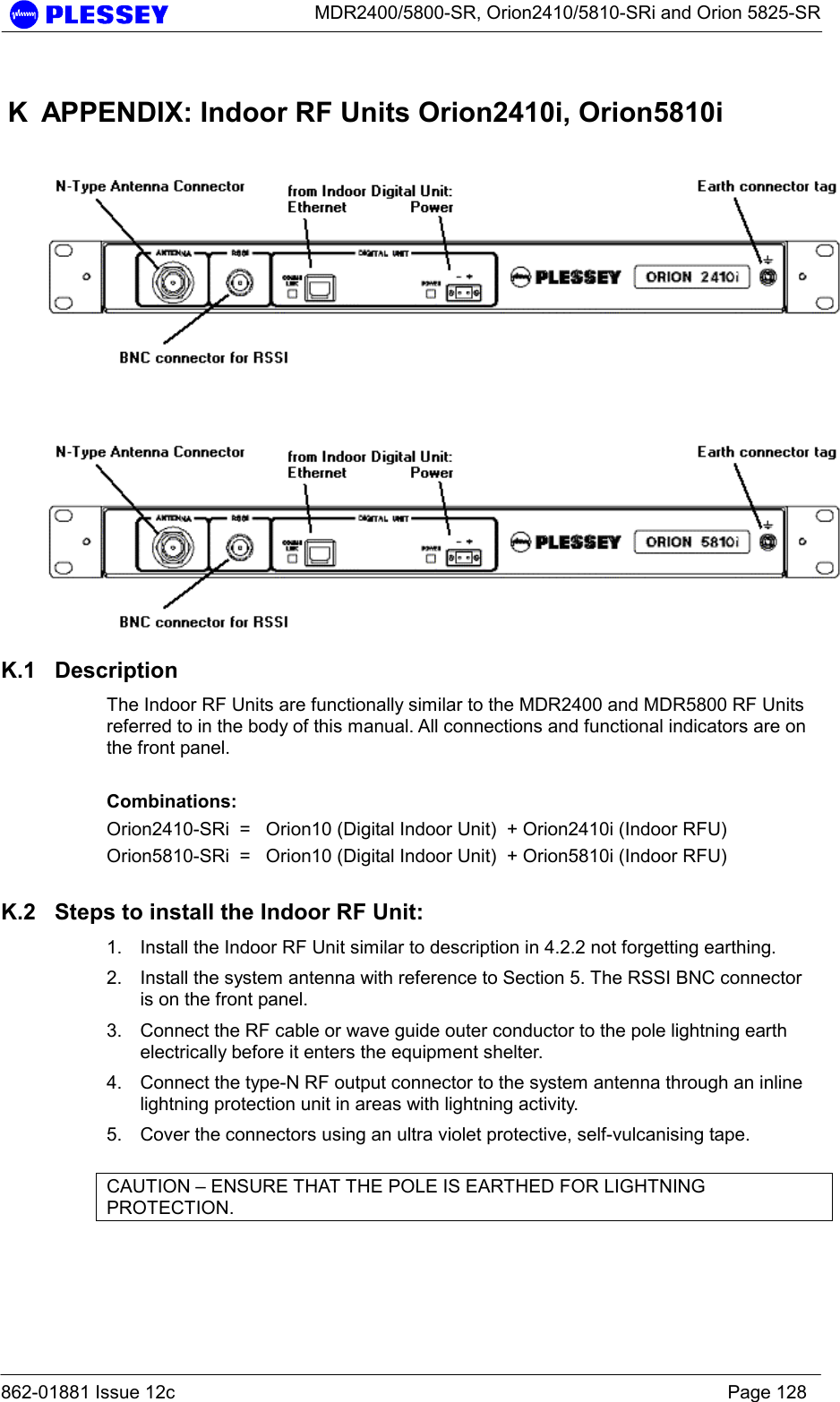
Aviat Networks 3ECJ68B3E PTP Radio User Manual 862 01881 12c
Aviat Networks PTP Radio 862 01881 12c
UserManual.wiki
>
Aviat Networks
>
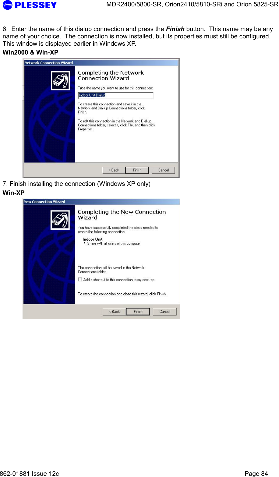
3ECJ68B3E User Manual
>
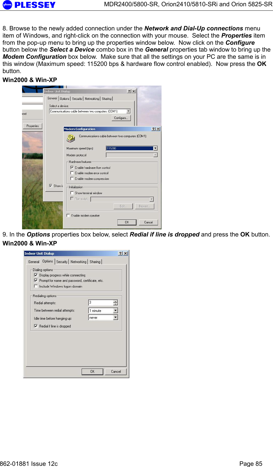
Manual 2 revised
Contents
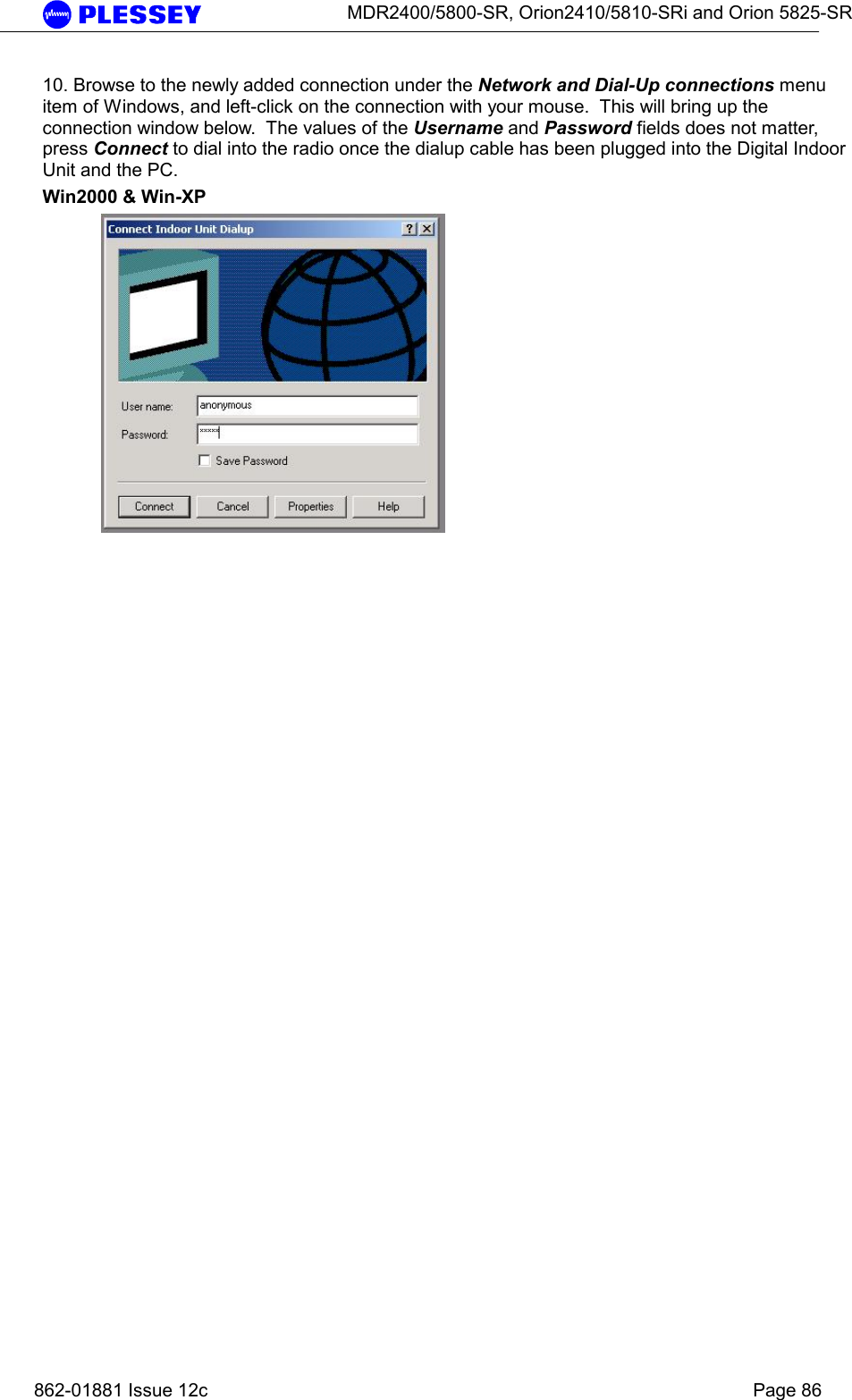
1.
Manual 1 revised
2.
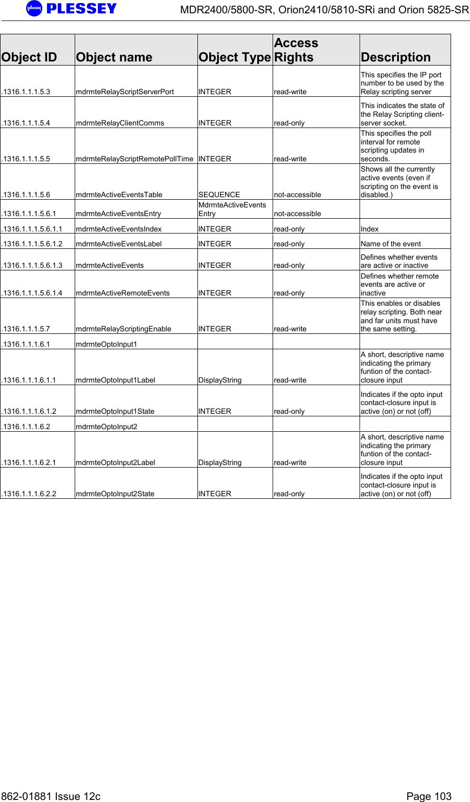
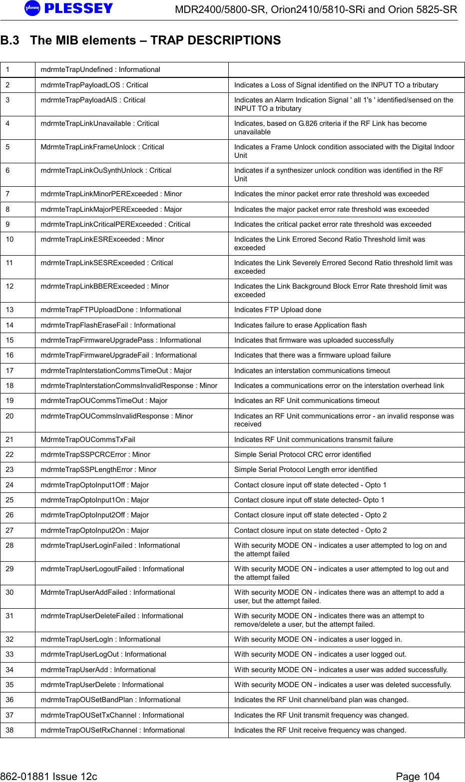
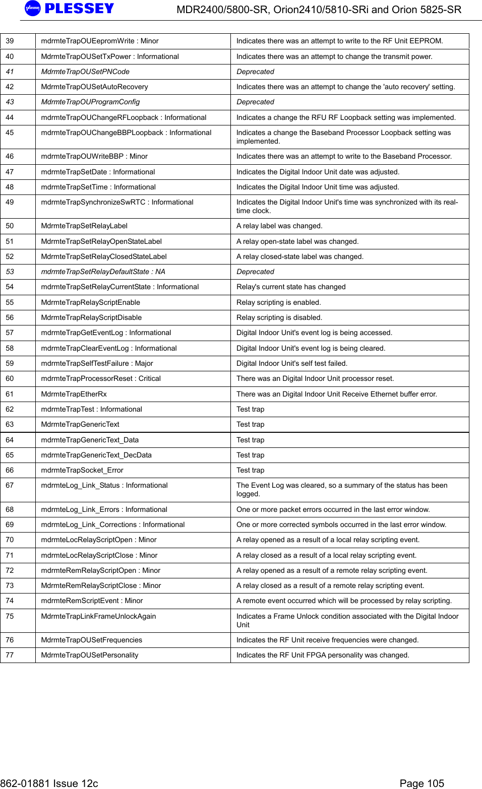
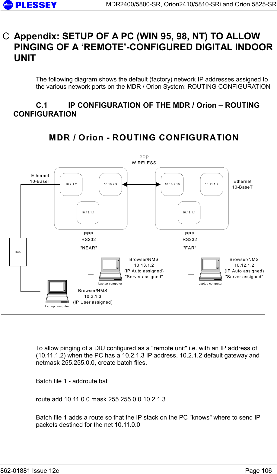
Manual 2 revised
Manual 2 revised
Navigation menu
Upload a User Manual
Namespaces
Wiki Guide
HTML
PDF
Info
Views
User Manual
Discussion / Help
Navigation
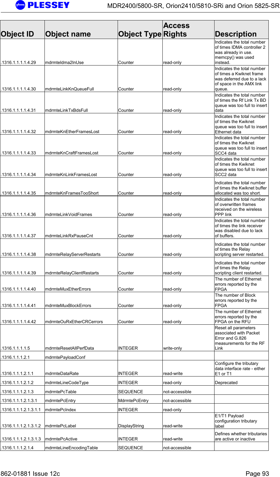
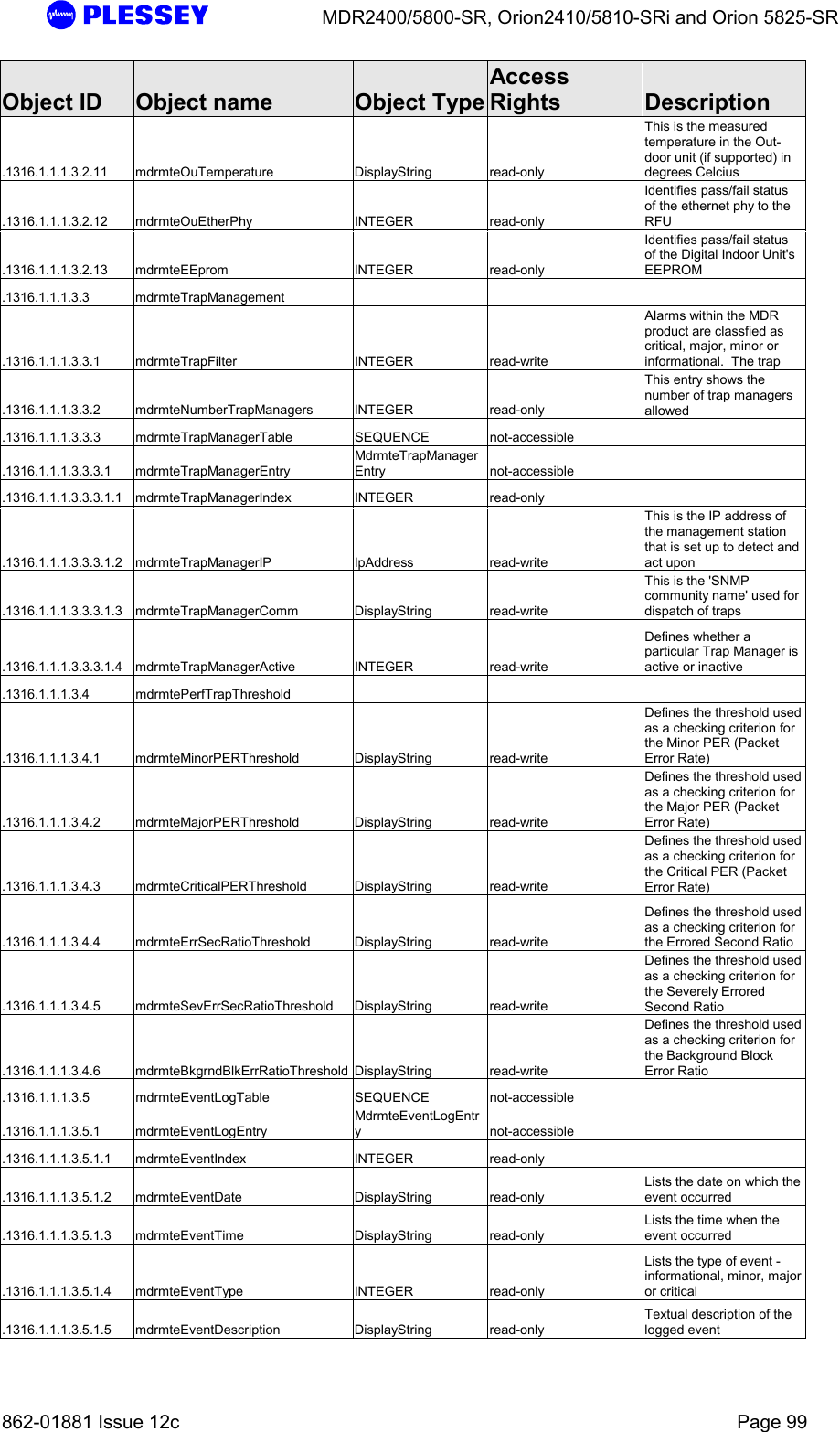
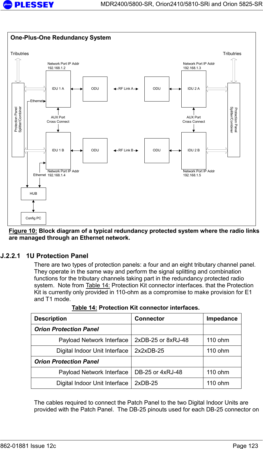
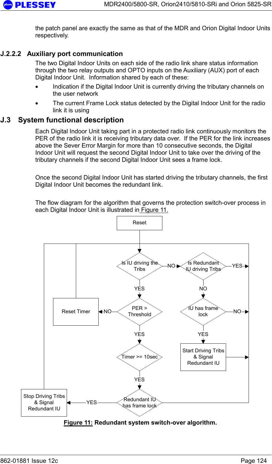
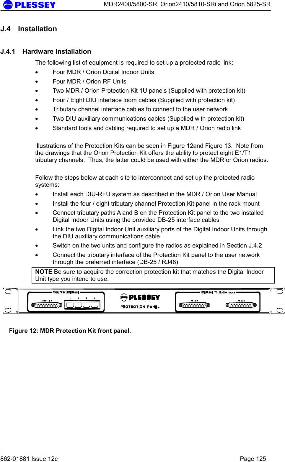
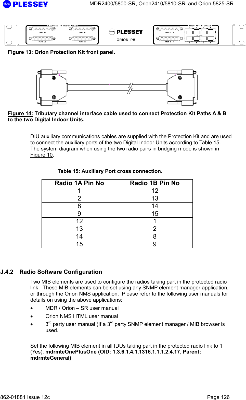
![MDR2400/5800-SR, Orion2410/5810-SRi and Orion 5825-SR 862-01881 Issue 12c Page 94 Object ID Object name Object TypeAccess Rights Description .1316.1.1.1.2.1.4.1 mdrmteLineEncodingEntry MdrmteLineEncodingEntry not-accessible .1316.1.1.1.2.1.4.1.1 mdrmteLineEncodingIndex INTEGER read-only .1316.1.1.1.2.1.4.1.2 mdrmteLineEncodingTribSelect INTEGER read-only Selects the trib, or group of tributaries to which encoding applies .1316.1.1.1.2.1.4.1.3 mdrmteLineEncoding INTEGER read-write Defines the line code types for the tributaries, either HDB3 or AMI for E1 .1316.1.1.1.2.2 mdrmteRFLinkConf .1316.1.1.1.2.2.1 mdrmteTxPower INTEGER read-write Allows setup of the output power available at the diplexer port of the RF Unit .1316.1.1.1.2.2.2 mdrmteBandPlan INTEGER read-write The MDR5800 RF Units operate in the 5.725 GHz to 5.850 GHz ISM frequency band. .1316.1.1.1.2.2.3 mdrmteTxFrequencyPlanD INTEGER read-write Frequency plan D allows independent control of transmit and receive frequencies. .1316.1.1.1.2.2.4 mdrmteRxFrequencyPlanD INTEGER read-write Refer to the mdrmteTxFrequencyPlanD description .1316.1.1.1.2.2.5 mdrmteTransmitBand INTEGER read-only This value is read from the RF Unit via the Digital Indoor Unit and defines whether it transmits in the .1316.1.1.1.2.2.6 mdrmteReserved2 INTEGER read-write .1316.1.1.1.2.2.7 mdrmteRegulations INTEGER read-only This parameter is read from the RF Unit via the Digital Indoor Unit and defines regulatory compliance of the RF Unit .1316.1.1.1.2.2.8 mdrmteAutoRecovery INTEGER read-write This feature is used if the user is installing a link from one side and there is no assistance on the opposite side of the link. It mitigates against the link failing and not being able to be .1316.1.1.1.2.2.9 mdrmteOURateOverride INTEGER read-write Depracated .1316.1.1.1.2.2.10 mdrmteOUDataRate INTEGER read-write A setable rate that allows a reduced transfer data rate over the RF Link .1316.1.1.1.2.2.11 mdrmteTxFrequencyCurrent INTEGER read-only This value [MHz] is read back from the RF Unit and defines the transmit frequency of the RF Unit .1316.1.1.1.2.2.12 mdrmteRxFrequencyCurrent INTEGER read-only This value [MHz] is read back from the RF Unit and defines the receive frequency of the RF Unit .1316.1.1.1.2.2.13 mdrmteNonAutoBandPlan INTEGER read-write Same as mdrMTEBandPlan setting in this MIB group except Autorecovery is not enabled - this allows control of the Outdoor .1316.1.1.1.2.2.14 mdrmteNonAutoTxFreqPlanD INTEGER read-write Same as mdrTxFrequencyPlanD setting in this MIB group except autorecovery is not enabled - this allows control of the Outdoor](https://usermanual.wiki/Aviat-Networks/3ECJ68B3E.Manual-2-revised/User-Guide-348151-Page-18.png)