Aviat Networks IRU600V4 IRU 600v4 MP User Manual
Aviat Networks (S) Pte. Ltd IRU 600v4 MP
User Manual

Eclipse
User Manual
Version 8.04.02
260-668066-001

USER MANUAL
260-668066-001 JULY 2018 III
Copyright & Terms of Use
July 2018
This documentation incorporates features and functions provided with Eclipse User Manual,
version 8.04.02.
Copyright © 2018 by Aviat Networks, Inc.
All rights reserved.
No part of this publication may be reproduced, transmitted, transcribed, stored in a retrieval
system, or translated into any language or computer language, in any form or by any means,
electronic, magnetic, optical, chemical, manual, or otherwise, without the prior written
permission of Aviat Networks Inc.
To request permission, contact techpubs@aviatnet.com.
Warranty
Aviat Networks makes no representation or warranties with respect to the contents hereof
and specifically disclaims any implied warranties or merchantability or fitness for any
particular purpose.
Further, Aviat Networks reserves the right to revise this publication and to make changes
from time to time in the content hereof without obligation of Aviat Networks to notify any
person of such revision or changes.
Safety Recommendations
The following safety recommendations must be considered to avoid injuries to persons
and/or damage to the equipment:
1. Installation and Service Personnel: Installation and service must be carried out by
authorized personnel who have the technical training and experience necessary to be
aware of any hazardous operations during installation and service, and of measures to
avoid any danger to themselves, to any other personnel, and to the equipment.
2. Access to the Equipment: Access to the equipment in use must be restricted to service
personnel only.
3. Safety Norms: Recommended safety norms are detailed in the Health and Safety
sections of the Eclipse User Manual.
4. Service Personnel Skill: Service personnel must have received adequate technical
training on telecommunications and in particular on the equipment and capabilities this
addendum refers to.
Trademarks
All trademarks are the property of their respective owners.
USER MANUAL
IV AVIAT NETWORKS

USER MANUAL
260-668066-001 JULY 2018 V
Aviat NetworksTechnical Support
Service and Technical Support:
For customer service and technical support, contact one of the regional Technical Help
Desks listed below.
Americas Technical Help Desk EMEA Technical Help Desk Asia Pacific Technical Help Desk
Aviat Networks, Inc.
San Antonio, TX
U.S.A.
Aviat Networks
Blantyre, Glasgow, Scotland
G72 0FB
United Kingdom
Aviat Networks
Clark Freeport Zone
Philippines 2023
Phone:+1 210 526 6345
Toll Free (USA):
+1 800 227 8332
Fax:+1 210 526 6315
Phone: +1 210 526 6345
Fax:
+44 16 9871 7204 (English)
+33 1 5552 8012 (French)
Phone: +1 210 526 6345
Fax: +63 45 599 5196
Email: TAC.AM@aviatnet.com Email: TAC.EMEA@aviatnet.com Email: TAC.APAC@aviatnet.com
Global Support Hotline: +1 210 526 6345
Call this phone number for support from anywhere in the world. Aviat Networks' Global
Support Hotline is available 24 hours a day, 7 days a week, providing uninterrupted support
for all our customers.
When you call our Global Support Hotline:
lYou will be greeted by an automated response that will ask you for your PIN#.
Request a PIN# here: http://aviatnetworks.com/contact-us/technical-
assistance/pin-request-form/.
lAs soon as you enter your PIN#, you will be transferred to our Global Technical
Helpdesk that will assist you with your technical issue.
lIf you do not have a PIN# your call will be answered by our Support Assurance
Desk. Your call will be supported and prioritized accordingly.
Or you can contact your local Aviat Networks office. Contact information is available on our
website at: http://www.aviatnetworks.com/services/customer-support/technical-
assistance/

USER MANUAL
VI AVIAT NETWORKS
Sales and Sales Support:
For sales information, contact one of the Aviat Networksheadquarters, or find your regional
sales office at: HTTP://WWW.AVIATNETWORKS.COM/.
Corporate Headquarters
California, USA
International Headquarters
Singapore
Aviat Networks, Inc.
860 N. McCarthy Blvd., Suite 200
Milpitas, CA 95035
U.S.A.
Phone: + 1 408 941 7100
Fax: + 1 408 941 7110
Toll Free for Sales Inquiries:
+ 1 888 478 9669
Aviat Networks (S) Pte. Ltd.
51 Changi Business Park Central 2
#04-10 The Signature
Singapore 486066
Phone: + 65 6496 0900
Fax: + 65 6496 0999>
Sales Inquiries:
+1-321-674-4252

USER MANUAL
260-668066-001 JULY 2018 VII
Product Compliance Notes
Eclipse EMC testing was completed using screened cable; if any other type of cable is used, it
may violate compliance.
Eclipse is a Class A product. In a domestic environment this product may cause radio
interference in which case the user may be required to take adequate measures. This
equipment is intended to be used exclusively in telecommunications centers.
Regulatory Information for 5.8 GHz Band
Eclipse IRU 600
The following regulatory information applies to license-free operation on the 5.8 GHz band of
IRU 600v2, IRU 600v3 and IRU 600v4.
FCC Notices
IRU 600v2/v3
lIRU 600, 5.8GHz, must be professionally installed and maintained.
lThis equipment has been tested and found to comply with the limits for a Class A
digital device, pursuant to Part 15 of the FCC rules. These limits are designed to
provide reasonable protection against harmful interference when the equipment
is operated in a commercial environment. This equipment generates, uses and
can radiate radio frequency energy and, if not installed and used in accordance
with the instruction manual, may cause harmful interference to radio
communications. Operation of this equipment in a residential environment is
likely to cause harmful interference in which case the user will be required to
correct the interference at their own expense.
lIRU 600, 5.8GHz, is compliant with the relevant parts of FCC CFR47, Part 15.407.
lTo ensure compliance with the FCC RF exposure requirements, a minimum
distance of 18 meters must be maintained between the antenna and any persons
whilst the unit is operational. This calculation is based on the maximum
conducted power and maximum antenna gain.
lIRU600, 5.8GHz, has been certified for use with a parabolic antenna with a
maximum gain of 45.9dBi or a flat panel antenna with a maximum gain of 28dBi.
lThe filters and software provided with this product allow for transmission only in
the frequency range 5725 – 5850 MHz to ensure compliance with Part 15.407.
lAccording to the conducted power limit in FCC CFR 47, Part 15.407, the power for
this device has been limited to 1W (30dBm) at the antenna port.
lFCC CFR47, Part 15.407 excludes the use of point-to-multipoint systems,

USER MANUAL
VIII AVIAT NETWORKS
omnidirectional applications and multiple co-located intentional radiators. This
system is only for fixed, point-to-point operation.
IRU 600v4
lIRU 600 , 5.8GHz, must be professionally installed and maintained.
lThis equipment has been tested and found to comply with the limits for a Class A
digital device, pursuant to Part 15 of the FCC rules. These limits are designed to
provide reasonable protection against harmful interference when the equipment
is operated in a commercial environment. This equipment generates, uses and
can radiate radio frequency energy and, if not installed and used in accordance
with the instruction manual, may cause harmful interference to radio
communications. Operation of this equipment in a residential environment is
likely to cause harmful interference in which case the user will be required to
correct the interference at their own expense.
lIRU 600 , 5.8GHz, is compliant with the relevant parts of FCC CFR47, Part 15.407.
lTo ensure compliance with the FCC RF exposure requirements, a minimum
distance of 18 meters must be maintained between the antenna and any persons
whilst the unit is operational. This calculation is based on the maximum
conducted power and maximum antenna gain.
lIRU 600, 5.8GHz, has been certified for use with a parabolic or a flat panel
antenna with a maximum gain of 43dBi.
lThe filters and software provided with this product allow for transmission only in
the frequency range 5725 – 5850 MHz to ensure compliance with Part 15.407. The
minimum transmit frequency settable in software is 5742.5MHz and the
maximum settable transmit frequency is 5832.5MHz.
lAccording to the conducted power limit in FCC CFR 47, Part 15.407, the power for
this device has been limited to 1W (30dBm) at the antenna port.
lFCC CFR47, Part 15.407 excludes the use of point-to-multipoint systems,
omnidirectional applications and multiple co-located intentional radiators. This
system is only for fixed, point-to-point operation.
lThis device complies with Part 15 of the FCC Rules. Operation is subject to the
following two conditions:
(1) this device may not cause harmful interference, and
(2) this device must accept any interference received, including interference that may
cause undesired operation.
lNo changes shall be made to the equipment without the manufacturer’s permission
as this may void the user’s authority to operate the equipment.
ISED (Canada) Notices
IRU 600v2/v3
lIRU600, 5.8GHz, must be professionally installed and maintained.
lIRU600, 5.8GHz, is compliant with Industry Canada RSS-210.

USER MANUAL
260-668066-001 JULY 2018 IX
lTo ensure compliance with the Industry Canada RF exposure requirements in
RSS-102, a minimum distance of 18 meters must be maintained between the
antenna and any persons whilst the unit is operational. This calculation is based
on the maximum conducted power and maximum antenna gain.
lIRU600, 5.8GHz, has been certified for use with a parabolic antenna with a
maximum gain of 45.9dBi or a flat panel antenna with a maximum gain of 28dBi.
lThe filters and software provided with this product allow for transmission only in
the frequency range 5725 – 5850 MHz to ensure compliance with the Canadian
band edges.
lAccording to the conducted power limit in RSS-210 Annex 8, the power for this
device has been limited to 1W (30dBm) at the antenna port.
IRU 600v4
lIRU 600, 5.8GHz, must be professionally installed and maintained.
lIRU 600, 5.8GHz, is compliant with Industry Canada RSS-247.
lTo ensure compliance with the Industry Canada RF exposure requirements in RSS-
102, a minimum distance of 18 meters must be maintained between the antenna
and any persons whilst the unit is operational. This calculation is
lbased on the maximum conducted power and maximum antenna gain.
lThe filters and software provided with this product allow for transmission only in
the frequency range 5725 – 5850MHz to ensure compliance with the Canadian band
edges.
lAccording to the conducted power limit in RSS-247 the power for this device has
been limited to 1W (30dBm) at the antenna port.
lThis device complies with ISED’s license-exempt RSSs. Operation is subject to the
following two conditions:
(1) This device may not cause interference; and
(2) This device must accept any interference, including interference that may cause
undesired operation of the device.
lThis radio transmitter (IC: 4469A-IRU600v4) has been approved by ISED to operate
with the antenna types listed below with the maximum permissible gain indicated.
Antenna types not included in this list, having a gain greater than the maximum gain
indicated for that type, are strictly prohibited for use with this device. IRU 600v4,
5.8GHz, has been certified for use with a parabolic or flat panel antenna with a
maximum gain of 43dBi. Please see Antennas certified for use with IRU 600v4 at
5.8GHz on page 125 for a list of the antennas approved for use with this radio.
lUnder ISED regulations, this radio transmitter may only operate using an antenna
of a type and maximum (or lesser) gain approved for the transmitter by ISED. To
reduce potential radio interference to other users, the antenna type and its gain
should be so chosen that the equivalent isotropically radiated power (e.i.r.p.) is not
more than that necessary for successful communication.

USER MANUAL
X AVIAT NETWORKS
ISDE (Canada)
IRU 600v2/v3
lL’IRU600, 5.8 GHz, doit être mis en oeuvre et maintenu par des professionnels.
lL’IRU600, 5.8 GHz, est conforme à la spécification RSS-210 d’Industrie Canada.
lPour assurer la conformité aux exigences d’exposition de la spécification RSS-
102 d’Industrie Canada, une distance minimum de 18 mètres entre l’antenne et
toute personne doit être assurée quand l’équipement est en fonctionnement. Ce
calcul est basé sur la puissance émise maximum et le gain maximum de
l’antenne.
lL’IRU600, 5.8 GHz, a été homologué avec utilisation d’une antenne parabolique
de gain maximum 45.9 dBi ou d’une antenne plane de gain maximum 28 dBi.
lLes filtres et le logiciel fournis avec ce produit permettent la transmission dans
la bande de fréquences 5725 – 5850 MHz seulement, pour assurer la conformité
avec les limites de bande canadiennes.
lEn conformité avec la limite de puissance émise de la spécification RSS-210
Annexe 8, la puissance de cet équipement a été limitée à 1 W (30dBm) à l’accès
de l’antenne.
IRU 600v4
lL’IRU 600, 5.8 GHz, doit être installé et maintenu par des professionnels.
lL’IRU 600, 5.8 GHz, est conforme à la spécification RSS-247 de l’Industrie du
Canada.
lPour assurer la conformité aux exigences d’exposition de la spécification RSS-102
de l’Industrie du Canada, une distance minimum de 18 mètres doit être assurée
entre l’antenne et une personne, quand l’équipement est en fonctionnement. Ce
calcul est basé sur la puissance émise maximum et le gain maximum de l’antenne.
lLes filtres et le logiciel fournis avec ce produit permettent la transmission dans la
bande de fréquences 5 725 – 5 850 MHz seulement, pour assurer la conformité
avec les limites de bande canadiennes.
lEn conformité avec la limite de puissance émise de la spécification RSS-247 la
puissance de cet équipement a été limitée à 1 W (30 dBm) à l’accès de l’antenne.
lCet appareil est conforme aux notre RSS exemptes de licence de l'ISED. Son
utilisation est soumise aux deux conditions suivantes:
(1) Cet appareil ne doit pas causer d'interférence; et
(2) Cet appareil doit accepter tout type d’interférence, y compris les interférences
susceptibles de provoquer un fonctionnement indésirable de l'appareil.
lCet émetteur radio (IC: 4469A-IRU600v4) a été approuvé par l’ISED pour
fonctionner avec les types d'antenne listés ci-dessous avec le gain maximum
admissible indiqué. Les types d'antennes non inclus dans cette liste, ayant un gain
supérieur au gain maximal indiqué pour ce type, sont strictement interdits pour une
utilisation avec cet appareil. L'IRU 600v4, 5,8 GHz, a été certifié pour une utilisation

USER MANUAL
260-668066-001 JULY 2018 XI
avec une antenne parabolique ou à une antenne plate d’un gain maximum de 43 dBi.
Se référer à la Antennas certified for use with IRU 600v4 at 5.8GHz on page 125
pour une liste d’antennes approuvée pour l’utilisation avec cette radio.
lEn vertu des règlements de l'ISED, cet émetteur radio ne peut fonctionner qu'avec
une antenne de type et un gain maximum (ou inférieur) approuvé pour l'émetteur
par l'ISED. Pour réduire les interférences radio potentielles avec d'autres
utilisateurs, le type d'antenne et son gain doivent être choisis de manière à ce que
la puissance isotrope rayonnée équivalente (eirp) ne soit pas supérieure à celle
nécessaire à établissement de la liaison.
International Use of 5.8 GHz
IRU600, 5.8 GHz, does not employ DFS, and as such the equipment cannot be deployed within
Europe or any country where DFS is a regulatory requirement for protection of radars.
Networking Devices in Electric Power Substations
For IEEE 1613 compliant products, category 7 Ethernet cables must be used in order to
ensure compliance.
NEBS Compliance
The Eclipse Node comprising the INU/ INUe and IRU 600 complies with the relevant NEBS
requirements under GR-1089-CORE and GR-63-CORE.
Such compliance requires installation of the Fan Air Filter option in the INUs, and adherence
to the health and safety and equipment installation practices described herein.
WEEE Directive
In accordance with the WEEE Directive (2012/19/EU), Eclipse is marked with the following
symbol:
This symbol indicates that this equipment should be collected separately for the purposes of
recovery and/or recycling.
For information about collection and recycling of Aviat Networks equipment please contact
your local Aviat Networks sales office. If you purchased your product via a distributor please
contact the distributor for information regarding collection and recovery/recycling.

USER MANUAL
XII AVIAT NETWORKS
More information on the WEEE Directive is available at our website:
http://www.aviatnetworks.com/products/compliance/weee/.
(WEEE is the acronym for Waste Electrical and Electronic Equipment)
RoHS Directive
Eclipse meets the requirements of ROHS directive 2011/65/EU.
Declaration of Conformity, Radio Equipment Directive
(RED), 2014/53/EU
Bulgaria
С настоящото Aviat Networks декларира,че този тип
радиосъоръжение Eclipse A600/Eclipse A600sp/Eclipse LL/STR 600 е
в съответствие с Директива 2014/53/ЕС.Цялостният текст на ЕС
декларацията за съответствие може да се намери на следния
интернет адрес:www.aviatnetworks.com
Czech Republic
Tímto Aviat Networks prohlašuje, že typ rádiového zařízení Eclipse
A600/Eclipse A600sp/Eclipse LL/STR 600 je v souladu se směrnicí
2014/53/EU. Úplné znění EU prohlášení o shoděje k dispozici na této
internetové adrese: www.aviatnetworks.com
Denmark
Hermed erklærer Aviat Networks, at radioudstyrstypen Eclipse
A600/Eclipse A600sp/Eclipse LL/STR 600 er i overensstemmelse med
direktiv 2014/53/EU. EU-overensstemmelseserklæringens fulde tekst
kan findes på følgende internetadresse: www.aviatnetworks.com
Germany Austria Switzerland Belgium
Luxembourg Netherlands Liechtenstein
Hiermit erklärt Aviat Networks, dass der Funkanlagentyp Eclipse
A600/Eclipse A600sp/Eclipse LL/STR 600 der Richtlinie 2014/53/EU
entspricht. Der vollständige Text der EU-Konformitätserklärung ist
unter der folgenden Internetadresse verfügbar:
www.aviatnetworks.com
Estonia
Käesolevaga deklareerib Aviat Networks, et käesolev raadioseadme
tüüp Eclipse A600/Eclipse A600sp/Eclipse LL/STR 600 vastab direktiivi
2014/53/EL nõuetele. ELi vastavusdeklaratsiooni täielik tekst on
kättesaadav järgmisel internetiaadressil: www.aviatnetworks.com
United Kingdom Ireland Malta
Hereby, Aviat Networks declares that the radio equipment type Eclipse
A600/Eclipse A600sp/Eclipse LL/STR 600 is in compliance with
Directive 2014/53/EU. The full text of the EU declaration of conformity is
available at the following internet address:
www.aviatnetworks.com
Spain
Por la presente, Aviat Networks declara que el tipo de equipo
radioeléctrico Eclipse A600/Eclipse A600sp/Eclipse LL/STR 600 es
conforme con la Directiva 2014/53/UE. El texto completo de la
declaración UE de conformidad está disponible en la dirección Internet
siguiente: www.aviatnetworks.com

USER MANUAL
260-668066-001 JULY 2018 XIII
Greece Cyprus
Με την παρούσα ο/ηAviat Networks, δηλώνει ότι ο ραδιοεξοπλισμός
Eclipse A600/Eclipse A600sp/Eclipse LL/STR 600 πληροί την οδηγία
2014/53/ΕΕ.Το πλήρες κείμενο της δήλωσης συμμόρφωσης ΕΕ
διατίθεται στην ακόλουθη ιστοσελίδα στο διαδίκτυο:
www.aviatnetworks.com
France Luxembourg Switzerland Belgium
Le soussigné, Aviat Networks, déclare que l'équipement
radioélectrique du type Eclipse A600/Eclipse A600sp/Eclipse LL/STR
600 est conforme à la directive 2014/53/UE. Le texte complet de la
déclaration UE de conformité est disponible à l'adresse internet
suivante: www.aviatnetworks.com
Italy Switzerland
Il fabbricante, Aviat Networks, dichiara che il tipo di apparecchiatura
radio Eclipse A600/Eclipse A600sp/Eclipse LL/STR 600 è conforme alla
direttiva 2014/53/UE. Il testo completo della dichiarazione di
conformità UE è disponibile al seguente indirizzo Internet:
www.aviatnetworks.com
Latvia
Ar šo Aviat Networks deklarē, ka radioiekārta Eclipse A600/Eclipse
A600sp/Eclipse LL/STR 600 atbilst Direktīvai 2014/53/ES. Pilns ES
atbilstības deklarācijas teksts ir pieejams šādāinterneta vietnē:
www.aviatnetworks.com
Lithuania
Aš, Aviat Networks, patvirtinu, kad radijo įrenginiųtipas Eclipse
A600/Eclipse A600sp/Eclipse LL/STR 600 atitinka Direktyvą
2014/53/ES. Visas ES atitikties deklaracijos tekstas prieinamas šiuo
interneto adresu: www.aviatnetworks.com
Netherlands Belgium
Hierbij verklaar ik, Aviat Networks, dat het type radioapparatuur
Eclipse A600/Eclipse A600sp/Eclipse LL/STR 600 conform is met
Richtlijn 2014/53/EU. De volledige tekst van de EU-
conformiteitsverklaring kan worden geraadpleegd op het volgende
internetadres: www.aviatnetworks.com
Croatia
Aviat Networks ovime izjavljuje da je radijska oprema tipa Eclipse
A600/Eclipse A600sp/Eclipse LL/STR 600 u skladu s Direktivom
2014/53/EU. Cjeloviti tekst EU izjave o sukladnosti dostupan je na
sljedećoj internetskoj adresi: www.aviatnetworks.com
Malta
B'dan, Aviat Networks, niddikjara li dan it-tip ta' tagħmir tar-radju
Eclipse A600/Eclipse A600sp/Eclipse LL/STR 600 huwa konformi mad-
Direttiva 2014/53/UE. It-test kollu tad-dikjarazzjoni ta' konformità tal-
UE huwa disponibbli f'dan l-indirizz tal-Internet li ġej:
www.aviatnetworks.com
Hungary
Aviat Networks igazolja, hogy a Eclipse A600/Eclipse A600sp/Eclipse
LL/STR 600 típusú rádióberendezés megfelel a 2014/53/EU irányelvnek.
Az EU-megfelelőségi nyilatkozat teljes szövege elérhetőa következő
internetes címen: www.aviatnetworks.com
Poland
Aviat Networks niniejszym oświadcza, że typ urządzenia radiowego
Eclipse A600/Eclipse A600sp/Eclipse LL/STR 600 jest zgodny z
dyrektywą2014/53/UE. Pełny tekst deklaracji zgodności UE jest
dostępny pod następującym adresem internetowym:
www.aviatnetworks.com

USER MANUAL
XIV AVIAT NETWORKS
Portugal
Aviat Networks niniejszym oświadcza, że typ urządzenia radiowego
Eclipse A600/Eclipse A600sp/Eclipse LL/STR 600 jest zgodny z
dyrektywą2014/53/UE. Pełny tekst deklaracji zgodności UE jest
dostępny pod następującym adresem internetowym:
www.aviatnetworks.com
Slovenia
Aviat Networks potrjuje, da je tip radijske opreme Eclipse A600/Eclipse
A600sp/Eclipse LL/STR 600 skladen z Direktivo 2014/53/EU. Celotno
besedilo izjave EU o skladnosti je na voljo na naslednjem spletnem
naslovu: www.aviatnetworks.com
Slovakia
Aviat Networks týmto vyhlasuje, že rádiové zariadenie typu Eclipse
A600/Eclipse A600sp/Eclipse LL/STR 600 je v súlade so smernicou
2014/53/EÚ. Úplné EÚ vyhlásenie o zhode je k dispozícii na tejto
internetovej adrese: www.aviatnetworks.com
Finland
Aviat Networks vakuuttaa, että radiolaitetyyppi Eclipse A600/Eclipse
A600sp/Eclipse LL/STR 600 on direktiivin 2014/53/EU mukainen. EU-
vaatimustenmukaisuusvakuutuksen täysimittainen teksti on saatavilla
seuraavassa internetosoitteessa: www.aviatnetworks.com
Sweden
Härmed försäkrar Aviat Networks att denna typ av radioutrustning
Eclipse A600/Eclipse A600sp/Eclipse LL/STR 600 överensstämmer med
direktiv 2014/53/EU. Den fullständiga texten till EU-försäkran om
överensstämmelse finns på följande webbadress:
www.aviatnetworks.com
Iceland
Hér með lýsir Aviat Networks yfir því aðEclipse A600/Eclipse
A600sp/Eclipse LL/STR 600 er í samræmi við grunnkröfur og aðrar
kröfur, sem gerðar eru í tilskipun 2014/53/EU.
Norway
Aviat Networks erklærer herved at utstyret Eclipse A600/Eclipse
A600sp/Eclipse LL/STR 600 er i samsvar med de grunnleggende krav og
øvrige relevante krav i direktiv 2014/53/EU.
România
Prin prezenta, Aviat Networks declarăcătipul de echipamente radio
Eclipse A600/Eclipse A600sp/Eclipse LL/STR 600 este în conformitate
cu Directiva 2014/53/UE. Textul integral al declarației UE de
conformitate este disponibil la următoarea adresăinternet:
www.aviatnetworks.com
Full declarations of conformity are available at:
http://aviatnetworks.com/doc/EclipseA600.pdf
http://aviatnetworks.com/doc/EclipseA600sp.pdf
http://aviatnetworks.com/doc/EclipseLL.pdf
http://aviatnetworks.com/doc/STR60011.pdf
http://aviatnetworks.com/doc/STR600L6U678.pdf
Country Availability Matrix
Aviat’s radios are classified under the Radio Equipment Directive (2014/53/EU) as Class 2
products. For details of where the equipment is intended to be used, see the country matrix
below.Aviat Networks intends to market this equipment where a cross (X) is shown.

USER MANUAL
260-668066-001 JULY 2018 XV
Band (GHz) L6 U6 07 08 10 11 13 15 18 23 26 28 32 38 42
Austria XXXXXXXXXXXXXXX
Belgium XXXX XXXXXXXXX
Bulgaria XXXXXXX XXXXXX
Cyprus XXXXXXXXXXXXXX
Czech Republic X X X X X X X X X X X
Denmark X X X X X X X X X X X X
Estonia XXXXXXXXXXXXXXX
Finland XXXXX XXXXXXXXX
France XXXXXXXXXXXXXX
Germany XXXXXXXXXXXXXXX
Greece X X X X X X X X
Hungary X X X X X X X X X X X
Iceland XXXXXXXXXXXX X
Ireland X X X X X X X X X X X
Italy XXXXXXXXXXX XX
Latvia X X X X X X X X X X X
Lithuania XXXXXXXXXXXXXX
Luxembourg X X X X X X X X X X X X X
Malta XXXXXXXXXX XXX
Netherlands X X X X X X X X X X X
Norway XXXX XXXXXXX XX
Poland XXXX XXXXXXXXXX
Portugal X X X X X X X X X X X X
Romania XXXXXXXXXXXXXXX
Slovak Republic X X X X X X X X X X X X X
Slovenia XXXX XXXXXXXXXX
Spain XX XXXXXXXXX X
Sweden X X X X X X X X X X X
Switzerland X X X X X X X X X X X X X X
United Kingdom X X X X X X X X X X X X X
IT SHOULD BE NOTED THAT A LICENSE TO OPERATE THIS EQUIPMENT WILL BE
REQUIRED AND THE RELEVANT REGULATOR MUST BE CONTACTED PRIOR TO
INSTALLATION AND COMMISSIONING.

USER MANUAL
XVI AVIAT NETWORKS
Contents
Copyright & Terms of Use iii
Aviat NetworksTechnical Support v
Product Compliance Notes vii
Regulatory Information for 5.8 GHz Band vii
Networking Devices in Electric Power Substations xi
NEBS Compliance xi
WEEE Directive xi
RoHS Directive xii
Declaration of Conformity, Radio Equipment Directive (RED), 2014/53/EU xii
Contents xvi
CHAPTER 1. ABOUT ECLIPSE 19
What Is Eclipse? 20
Installation and User Prerequisites 21
About the Eclipse Documentation 22
Conventions and Terminology 23
CHAPTER 2. HEALTH AND SAFETY 25
General Health and Safety 26
Operator Health and Safety 27
General Hazards 28
RF Exposure Guidelines 32
ODU 600 32
STR 600 33
ODU 300 Series 33
Routine Inspection and Maintenance 37
Routine Inspections 37
Trend Analysis 37
Fault Analysis 38
Training 38
Spares 38
CHAPTER 3. SYSTEM OVERVIEW 39
Eclipse Node and Packet Node 40
Node Indoor Units 41
INU 41
INUe 42
Plug-in Cards 42
Plug-in Cards Overview 43
Protection Options 53

USER MANUAL
260-668066-001 JULY 2018 XVII
Link/Path Protection 53
Interface Protection 53
Network/Data Protection 54
Platform Protection 55
Eclipse Packet Node and Data Packet Plane 55
Data Packet Plane 55
Advanced Adaptive Coding and Modulation (ACM) 56
Platforms 57
Platform Layout 57
Slot Assignments 58
Eclipse Terminals 60
300 Series Indoor Units 60
IDU 300 Series Overview 61
Eclipse Radio Frequency Units 67
IRU 600 67
IRU 600 Variants 68
5.8 GHz Unlicensed Band 74
Eclipse Licensing 76
Eclipse Configuration and Management 80
Eclipse Antennas 81
Eclipse Power Supply 82
CHAPTER 4. INTRODUCTION TO ECLIPSE INSTALLATION 83
Installation Overview 84
Before Going On Site 85
Installation Tools and Materials 85
Unpacking the Eclipse Equipment 86
CHAPTER 5. IRU 600 INSTALLATION 87
IRU 600 Compatibility 88
IRU 600 Installation Procedure 90
Chassis Installation 90
Chassis Grounding 93
NEBS Compliant Grounding 93
Safety Requirements for Equipment Grounding 94
Waveguide Installation 94
Waveguide Connection to ACU 94
Power Supply Connection 95
Insertion Loss Labels 97
Expansion Port Use 97
FAN Module 97
Chassis Adapter Kit for IRU 600v3 and IRU 600v4 RFUs 98
Next Steps 100
CHAPTER 6. INSTALLING THE INU AND INUE101
INU/INUe Description 102
INU Front Panel Layout 102

USER MANUAL
XVIII AVIAT NETWORKS
INU Power Supply 103
Power Consumption and INU Load Maximums 103
PCC +24 Vdc Operation 111
Power Cables 112
Fuses 113
FAN Air Filter Option 113
Fan Air Filter Installation 113
Power Line Filter Option 114
INU/INUe Installation Requirements 115
Installation 118
Plug-in Installation Requirements 121
APPENDIX A. ANTENNAS CERTIFIED FOR USE WITH IRU
600V4AT 5.8GHZ125


CHAPTER 1ABOUT ECLIPSE
What Is Eclipse?
The Eclipse Microwave Radio System comprises the indoor mounted Node or Terminal, and
asscociated indoor or outdoor radio frequency units.
lEclipse Node supports multiple point-to-point radios for Ethernet, PDH, SDH, on a
single rack-mounted platform, to form a complete network node for star or ring
configurations on frequency bands 5 to 42 GHz. Plug-in modules provide the
customization for link and user interface requirements.
lEclipse Terminal is optimized for single-link installations or where back-to-back
network connection of terminals is preferred. Terminals may also be used on
spur links from an Eclipse Node. Different versions are available for Ethernet,
PDH, SDH, on frequency bands 5 to 42 GHz.
20 JULY 2018 AVIAT NETWORKS

ABOUT ECLIPSE CHAPTER 1
Installation and User Prerequisites
To install, commission, and maintain Eclipse, we recommend you have the following
knowledge and skills:
lA basic understanding of the principles of microwave transmission.
lInstallation and maintenance experience on Ethernet, PDH and SDH digital
microwave radio systems.
lFamiliarity with Ethernet and/or SDH multiplexing where these traffic options are
to be employed on Eclipse.
lFamiliarity with the operation of a PC using the Windows operating system.
lA thorough understanding of Eclipse systems, configuration, and diagnostics
from attendance of an Aviat Networks training course on Eclipse.
WARNING: Follow health and safety procedures at all times! See Health and Safety
on page 25 for complete details.
AVIAT NETWORKS JULY 2018 21

CHAPTER 1ABOUT ECLIPSE
About the Eclipse Documentation
This documentation provides information on installing, configuring, commissioning, and
troubleshooting an Eclipse Microwave Radio system. Technical descriptions are at a
module and system level.
Intended Audience
This information is for use by trained technicians or engineers. It does not provide
information or instruction on basic technical procedures. Aviat Networks recommends you
read the relevant sections of this manual thoroughly before beginning any installation or
operational procedures.
Organization
This manual is divided into five volume-level sections:
lHealth and Safety Requirements
lSystem Overview
lInstallation
lConfiguration and Diagnostics
lCommissioning and Troubleshooting
lAppendices
Additional Resources
The resources identified below contain additional information.
lEclipse Platform Product Description. Operational and application data for
Eclipse Packet Node.
lIDU GE3 16x Product Description. Operational and application data for
Eclipse IDU GE3 16x.
lVarious White Papers.
lAviat Networks Microwave Radio System Best Practices Guide. (PN 260-
668029-001). Use to assist in installing, commissioning, and
troubleshooting Eclipse and other microwave radio products.
Contact Aviat Networks or your supplier for availability.
22 JULY 2018 AVIAT NETWORKS

ABOUT ECLIPSE CHAPTER 1
Conventions and Terminology
This document uses the following conventions and terminology.
Graphic Cues
The following items have graphic cues to identify important supporting information.
NOTE: Anote item identifies additional information about a procedure or
function.
CAUTION: Acaution item identifies important information pertaining to actions that may
cause damage to equipment, loss of data, or corruption of files.
WARNING: Awarning item identifies a serious physical danger or major possible
problem.
Font Changes
Bold font is used for the names of on-screen elements such as; fields, buttons, and drop-
down selection lists, keywords, commands and for keys on the keyboard.
Courier font in blue text is used to indicate commands that the user needs to type in.
WTM4100# show radio-carrier status Carrier1/1
Any responses or report output from a command is shown as brown text and indented.
radio-carrier status Carrier1/1
oper-status up
Italic font is used to emphasize words and phrases, to introduce new terms, and for the
titles of printed publications.
Common Terminology
Click or Select: Point the mouse pointer at the item you want to select, then quickly press and
release the left mouse button.
Right-Click: Point the mouse pointer at the item you want to select, then quickly press and
release the right mouse button.
AVIAT NETWORKS JULY 2018 23

HEALTH AND SAFETY CHAPTER 2
Chapter 2. Health and Safety
This section includes the following health and safety information:
lGeneral Health and Safety on page 26
lOperator Health and Safety on page 27
lGeneral Hazards on page 28
lRF Exposure Guidelines on page 32
All personnel must comply with the relevant health and safety practices when working on or
around Eclipse radio equipment.
The Eclipse system has been designed to meet relevant US and European health and safety
standards as outlined in IEC Publication 60950-1.
Eclipse is a Class A product. It is intended to be used exclusively in telecommunications
centers.
Local safety regulations must be used if mandatory. Safety instructions in this Volume
should be used in addition to the local safety regulations. In the case of conflict between
safety instructions stated herein and those indicated in local regulations, mandatory local
norms will prevail. Should not local regulations be mandatory, then safety norms herein
will prevail.
WARNING: Hot Surfaces - the external surfaces of an ODU 600v2 can be hot to touch,
especially at high ambient temperatures. A hot surfaces warning icon is displayed on
the product:
AVIAT NETWORKS JULY 2018 25

CHAPTER 2HEALTH AND SAFETY
General Health and Safety
This table describes general health and safety information about the Eclipse radio.
Topic Information
Flammability Eclipse is designed and constructed to minimize the risk of smoke and fumes during
a fire.
Hazardous
Materials
No hazardous materials are used in the construction of the equipment.
Hazardous
Voltage
Eclipse meets global product safety requirements for safety extra-low voltage (SELV)
rated equipment where the input voltage must be 48V nominal, 60V maximum.
Safety Signs External warning signs or other indicators on the equipment are not required.
Surface
Temperatures
The external equipment surfaces do become warm during operation due to heat
dissipation. However, the temperatures reached are not considered hazardous.
26 JULY 2018 AVIAT NETWORKS

HEALTH AND SAFETY CHAPTER 2
Operator Health and Safety
The following table describes the precautions that relate to installing or working on an
Eclipse radio.
Topic Information
Equipment
Protrusions
Eclipse has been designed to be free of unnecessary protrusions or sharp surfaces
that may catch or otherwise cause injury during handling. However, always take
care when working on or around the equipment.
Laser and Fiber
Optic Cable Hazards
Eclipse fiber optic transmitters are IEC60825-1 / 21CFR1040-1 Class I compliant
and present no danger to personnel in normal use. However:
Do not look into active unterminated optical ports or fibers. If visual inspection is
required ensure the equipment is turned off or, if a fiber cable, disconnect the far
end.
Follow the manufacturer's instructions when using an optical test set. Incorrect
calibration or control settings could result in hazardous levels of radiation.
Protect/cover unconnected optical fiber connectors with dust caps.
Place all optical fiber cuttings in a suitable container for safe disposal. Bare fibers
and fiber scraps can easily penetrate the skin and eyes.
Lifting Equipment Be careful when hoisting or lifting an antenna or ODU during installation or
maintenance. A large antenna with its mounting hardware can weigh in excess of
100kg (220 lb) and require specialized lifting equipment and an operator trained
and certified in its use.
Protection from RF
Exposure: Eclipse
Eclipse radio transceivers do not generate RF fields intense enough to cause RF
burns. However, when installing, servicing or inspecting an antenna always comply
with the Protection from RF Exposure guidelines under General Hazards on
page 28.
Safety Warnings When a practice or procedure poses implied or potential harm to the user or to the
Eclipse equipment, a warning is included in this manual.
AVIAT NETWORKS JULY 2018 27

CHAPTER 2HEALTH AND SAFETY
General Hazards
The following table describes the general hazards that must be addressed when planning
and installing an Eclipse system.
For more information on health and safety when using Aviat Networks products, refer to the
Best Practices Guide.
Topic Information
Airflow Requirements Rack installations must be made so the airflow required for safe and correct
operation of Eclipse is not compromised. For the fan-cooled Eclipse INUs
and fan-cooled Eclipse IDUs, unobstructed air passage must be maintained
to each side of the chassis, which requires a minimum of 50 mm (2 inches)
of side spacing to any rack panels, cable bundles or similar. Unused slots on
the INU/INUe must be fitted with a blanking panel.
Where a Fan Air Filter is installed in an INU it must not be allowed to
become clogged with dust. Replace when necessary.Inspection must be at
not more than 12 monthly intervals when installed in telecommunications
equipment room controlled-air environments. Otherwise, inspection is
required at more frequent intervals.
EMC Eclipse has been tested for and meets EMC Directive 89/336/EEC. The
equipment was tested using screened cable; if any other type of cable is
used, it may violate compliance.
Eclipse is a Class A product. In a domestic environment this product may
cause radio interference in which case the user may be required to take
adequate measures. This equipment is intended to be used exclusively in
telecommunications centers.
ESD ESD (electrostatic discharge) can damage electronic components. Even if
components remain functional, ESD can cause latent damage that results in
premature failure. Always wear proper ESD grounding straps when
changing or handling the plug-in cards and avoid hand contact with the
PCB back-plane and top-plane. Connect your ESD grounding strap to the
combined ESD and ground connector on the INU rack ear. Spare plug-in
cards or cards to be returned for service must be enclosed in an anti-static
bag. When removing a card from the anti-static bag for installation in an
INU, or placing a card in a bag, do so at the INU and only when connected to
the INU via your ESD grounding strap.
Circuit Overloading When connecting an Eclipse terminal, determine the effect this will have on
the power supply circuit protection devices, and supply wiring. Check
Eclipse power consumption specifications and the supply capability of the
power supply system. This check of capacity must extend to the dc power
supply and not just to an intermediate connection point.
28 JULY 2018 AVIAT NETWORKS

HEALTH AND SAFETY CHAPTER 2
Topic Information
Eclipse Indoor Unit and
DC Supply Grounding
The ground for Eclipse indoor unit(s) must be connected directly to the dc
supply system ground conductor, or to a bonding jumper from a grounding
terminal bar, or bus to which the dc supply system grounding is connected.
Intrabuilding interfaces
and cabling for NEBS
compliance
Intrabuilding connections to/from Eclipse ports must only be connected via
intrabuilding or unexposed wiring or cabling.
Intrabuilding ports MUST NOT be metallically connected to interfaces that
connect to the OSP or its wiring. These interfaces are designed for use as
intrabuilding interfaces only (Type 2 or Type 4 ports as described in GR-
1089-CORE, Issue 4) and require isolation from the exposed OSP cabling.
The addition of Primary Protectors is not sufficient protection in order to
connect these interfaces metallically to OSP wiring.
Shielded and grounded cables must be used for intrabuilding cabling
to/from Eclipse ports. Cables must be grounded at both ends.
Protection from RF
Exposure
When installing, servicing or inspecting an antenna always comply with the
following:
Locate the antenna such that it does not infringe the RF exposure
guidelines for general public. Refer to General Public Compliance
Boundary in RF Exposure Guidelines on page 32.
Stay aware of the potential risk of RF exposure and take appropriate
precautions. Refer to Occupational Compliance Boundary in RF
Exposure Guidelines on page 32.
Do not stand in front of or look into an antenna without first ensuring the
associated transmitter or transmitters are switched off.
Do not look into waveguide or into the waveguide port of an RFU without
first ensuring the associated transmitter or transmitters are switched off.
At a multi-antenna site ask the site owner or operator for details of other
radio services active at the site and for their
requirements/recommendations for protection against potentially
harmful exposure to RF radiation.
When it is not possible to switch transmitters off at a multi-antenna site
and there is potential for exposure to harmful levels of RF radiation, wear
a protective suit.
Fiber Optic Cables Handle optical fibers with care. Keep them in a safe and secure location
during installation.
Do not attempt to bend them beyond their minimum bend radius.
Protect/cover unconnected optical fiber connectors with dust caps.
Ground Connections Reliable grounding of the Eclipse system must be maintained. Refer to
instructions in the manual for grounding of waveguide, ODU cable, lightning
surge suppressor, ODU, and indoor unit.
There must be no switching or disconnecting devices fitted in ground
conductors.
Lightning Surge
Suppressor
Eclipse ODU cables must be fitted with the specified surge suppressor at
the ODU unless the ODU has a built-in suppressor.
AVIAT NETWORKS JULY 2018 29

CHAPTER 2HEALTH AND SAFETY
Topic Information
Mains Power Supply
Routing
Eclipse dc power, IF, tributary, auxiliary and NMS cables are not to be routed
with any AC mains power lines. They are also to be kept away from any
power lines which cross them.
Maximum Ambient
Temperature
The maximum ambient temperature (Tmra) for Eclipse indoor units and
outdoor units is +55° C (131° F). Special conditions apply to the INUs - for
more information see Power Consumption within INU Power Supply on
page 103. To ensure correct operation and to maximize long term
component reliability, ambient temperatures must not be exceeded.
Operational specification compliance is not guaranteed for higher ambients.
Mechanical Loading When installing an indoor unit in a rack, ensure the rack is securely
anchored. Ensure that the additional loading of an Eclipse indoor unit or
units will not cause any reduction in the mechanical stability of the rack.
Power Supply
Connection
The Eclipse INU/INUe and IDUs have the +ve pin on their dc power supply
connector connected to chassis ground. It must be used with a
-48Vdc power supply which has a +ve ground; the power supply ground
conductor is the +ve supply to the radio. For NEBS compliance the battery
return connection is to be treated as a common DC return (DC-C), as defined
in GR-1089-CORE.
For IRU 600 variants that require a separate wide-mouth +/-21 to
+/-60 Vdc power supply connection, both pins on its power supply connector
are isolated from chassis ground. For NEBS compliance the battery return
connection is to be treated as an isolated DC return (DC-I), as defined in GR-
1089-CORE.
The d.c. supply source must be located within the same premises as the
equipment.
Connection to D.C. Supply
Ground
CAUTION: The Eclipse INU/INUe and IDUs have a connection
between the earthed conductor of the d.c. supply circuit and the
earthing conductor.
This equipment must be connected directly to the d.c. supply system
grounding electrode conductor or to a bonding jumper from a grounding
terminal bar or bus to which the d.c. supply system grounding electrode is
connected.
Switching or disconnecting devices must not be in the grounded circuit
conductor between the d.c. source and the point of connection of the
grounding electrode conductor.
This equipment must be located in the same immediate area (such as,
adjacent cabinets) as any other equipment that has a connection between
the grounded conductor of the same d.c. supply circuit and the grounding
conductor, and also the point of grounding of the d.c. system. The d.c.
system shall not be grounded elsewhere.
Power Supply
Disconnect
An appropriate disconnect device for the -48 Vdc or +24 Vdc power supply
unit must be provided as part of the building installation.
30 JULY 2018 AVIAT NETWORKS

HEALTH AND SAFETY CHAPTER 2
Topic Information
Rack Mount Temperature
Considerations
If the Eclipse indoor unit is installed in a closed or multi-unit rack assembly,
the operating ambient temperature of the rack environment may be greater
than room ambient. The maximum ambient temperature applies to the
immediate operating environment of the Eclipse indoor unit, which, if
installed in a rack, is the ambient within the rack.
Restricted Access The Eclipse system must be installed in restricted access sites. The indoor
unit and associated power supply must be installed in restricted areas, such
as dedicated equipment rooms, closets, cabinets, or the like. Access to the
tower and antenna location must be restricted
NOTE: F or U S A:
In restric ted acc ess areas install the E clips e s ys tem in ac c ordance with
articles 110-26 and 110-27 of the 2002 National Elec tric al Code
ANSI/NFPA 70, or to any subs equent update to this c ode for the rel evant
articles.
AVIAT NETWORKS JULY 2018 31

CHAPTER 2HEALTH AND SAFETY
RF Exposure Guidelines
Data is provided for Eclipse ODU 600, STR 600 and ODU 300.
ODU 600
The following MPE (maximum permissible exposure) calculations have been produced in
accordance with the guidelines of EN 50383/EN 50385 and Section 1.1310 of the FCC’s
rules. These calculations represent the maximum conducted output power and the
maximum antenna gain, by frequency range. These calculations are based on the exposure
requirements for the general public. If the antennas used with this device exceed the gain
values stated below, the installer must take additional precautions and re-calculate the
minimum compliance boundary.
Table 1. MPE Guidelines for ODU 600
Frequency Range
(GHz)
Minimum Com-
pliance Distance
(m)
TX conducted
power (dBm)
Antenna Gain
(dBi)
4.4 – 5.0 15.86 +30.0 45.0
5.925 - 7.11 9.78 +31 39.8
7.125 – 7.9 12.75 +32 41.1
7.725 - 8.5 11.36 +31 41.1
10.7 – 11.7 10.48 +27 44.4
12.75 – 13.25 11.23 +26.5 45.5
14.4 – 15.35 12.61 +26.5 46.5
17.7 – 19.7 10.49 +23 48.4
21.2 - 23.632 13.2 +23.5 49.9
24.25 – 26.483 12.31 +25 47.8
27.5 – 29.5 7.09 +25 43.0
31.8 – 33.4 6.18 +23 43.8
37.0 – 39.46 7.78 +23 45.8
40.5 - 43.5 6.54 +21 46.3
Operation of ODU 600 on 5.8 GHz Unlicensed Band, USA and Canada
To ensure compliance with FCC and Industry Canada RF exposure requirements, a
minimum distance of 18 meters must be maintained between the ODU 600 antenna and any
persons whilst the unit is operational. This calculation is based on the maximum conducted
power and maximum antenna gain permitted by FCC and Industry Canada RF for this band.
32 JULY 2018 AVIAT NETWORKS

HEALTH AND SAFETY CHAPTER 2
STR 600
The following MPE (maximum permissible exposure) calculations have been produced in
accordance with the guidelines of EN 50383/EN 50385 and Section 1.1310 of the FCC’s
rules. These calculations represent the maximum conducted output power and the
maximum antenna gain, by frequency range. These calculations are based on the exposure
requirements for the general public. If the antennas used with this device exceed the gain
values stated below, the installer must take additional precautions and re-calculate the
minimum compliance boundary.
Table 2. MPE Guidelines for STR 600
Frequency Range
(GHz)
Minimum Com-
pliance Distance
(m)
TX conducted
power (dBm)
Antenna Gain
(dBi)
4.4 – 5.0 17.80 +31.0 45.0
5.925 - 7.11 13.04 +33.5 39.8
7.125 – 7.9 15.15 +33.5 41.1
7.725 -8.5 13.50 +32.5 41.1
10.0 – 11.7 15.69 +30.5 44.4
ODU 300 Series
The following MPE (maximum permissible exposure) calculations for the Eclipse ODU 300
series have been produced in accordance with the guidelines of EN 50383/EN 50385. These
calculations represent examples only and do not include every possible combination of
output power and antenna gain.
Occupational is defined as: “The occupationally exposed population consists of adults who
are generally exposed under known conditions and are trained to be aware of potential risk
and to take appropriate precautions”.
Table 3. MPE Guidelines for ODU 300
5 GHz (4.4 - 5.0 GHz)
Transmit Power
(dBm)
Antenna Gain (dBm) Compliance Boundary
General Public (m)
Compliance Boundary
Occupational (m)
30.5 39.3 8.77 3.91
30.5 32.6 4.06 1.81
0.5 39.3 0.28 0.12
0.5 32.6 0.13 0.06
L6/U6 GHz (5.925 - 7.11 GHz)
AVIAT NETWORKS JULY 2018 33

CHAPTER 2HEALTH AND SAFETY
Transmit Power
(dBm)
Antenna Gain (dBm) Compliance Boundary
General Public (m)
Compliance Boundary
Occupational (m)
30.5 41.5 11.30 5.03
30.5 31.2 3.45 1.54
0.5 41.5 0.36 0.16
0.5 31.2 0.11 0.05
7/8 GHz (7.125 - 8.5 GHz)
Transmit Power
(dBm)
Antenna Gain (dBm) Compliance Boundary
General Public (m)
Compliance Boundary
Occupational (m)
30.5 42.9 13.28 5.91
30.5 30.24 3.15 1.40
5.0 42.9 0.71 0.31
5.0 30.4 0.17 0.07
10 GHz (10.0 - 10.68 GHz)
Transmit Power
(dBm)
Antenna Gain (dBm) Compliance Boundary
General Public (m)
Compliance Boundary
Occupational (m)
26.0 34.3 2.94 1.31
26.0 33.7 2.74 1.22
-4.0 34.3 0.09 0.04
-4.0 33.7 0.09 0.04
11 GHz (10.7 - 11.7 GHz)
Transmit Power
(dBm)
Antenna Gain (dBm) Compliance Boundary
General Public (m)
Compliance Boundary
Occupational (m)
25.0 46.2 10.31 4.59
25.0 27.7 1.23 0.55
2.5 46.2 0.77 0.34
2.5 27.7 0.09 0.04
13 GHz (12.75- 13.25 GHz)
Transmit Power
(dBm)
Antenna Gain (dBm) Compliance Boundary
General Public (m)
Compliance Boundary
Occupational (m)
28.0 47.3 16.53 7.36
28.0 29.6 2.15 0.96
0.0 47.3 0.66 0.29
0.00 47.3 0.66 0.29
0.00 29.6 0.09 0.04
15 GHz (14.4- 15.35 GHz)
Transmit Power
(dBm)
Antenna Gain (dBm) Compliance Boundary
General Public (m)
Compliance Boundary
Occupational (m)
34 JULY 2018 AVIAT NETWORKS

HEALTH AND SAFETY CHAPTER 2
27.0 46.4 13.28 5.91
27.0 30.8 2.20 0.98
-1.0 46.4 0.53 0.24
-1.0 30.8 0.09 0.04
18 GHz (17.7-19.7 GHz)
Transmit Power
(dBm)
Antenna Gain (dBm) Compliance Boundary
General Public (m)
Compliance Boundary
Occupational (m)
21.5 48.0 8.48 3.77
21.5 32.8 1.47 0.66
-3.0 48.0 0.50 0.22
-3.0 32.8 0.09 0.04
23 GHz (21.2-23.632 GHz)
Transmit Power
(dBm)
Antenna Gain (dBm) Compliance Boundary
General Public (m)
Compliance Boundary
Occupational (m)
21.5 49.2 9.73 4.33
21.5 34.4 1.77 0.79
-3.0 49.2 0.58 0.26
-3.0 34.4 0.11 0.05
26 GHz (24.52- 26.483 GHz)
Transmit Power
(dBm)
Antenna Gain (dBm) Compliance Boundary
General Public (m)
Compliance Boundary
Occupational (m)
15.5 46.0 3.37 1.50
15.5 35.9 1.05 0.47
-4.5 46.0 0.34 0.15
-4.5 35.9 0.11 0.05
28 GHz (27.5- 29.5GHz)
Transmit Power
(dBm)
Antenna Gain (dBm) Compliance Boundary
General Public (m)
Compliance Boundary
Occupational (m)
15.0 48.1 4.06 1.81
15.0 36.5 1.07 0.48
-5.0 48.1 0.41 0.18
-5.0 36.5 0.11 0.05
32 GHz (31.8- 33.4 GHz)
Transmit Power
(dBm)
Antenna Gain (dBm) Compliance Boundary
General Public (m)
Compliance Boundary
Occupational (m)
17.5 43.5 3.19 1.42
17.5 37.5 1.60 0.71
AVIAT NETWORKS JULY 2018 35

CHAPTER 2HEALTH AND SAFETY
-5.0 43.5 0.24 0.11
-5.0 37.5 0.12 0.05
38 GHz (37.0- 39.46 GHz)
Transmit Power
(dBm)
Antenna Gain (dBm) Compliance Boundary
General Public (m)
Compliance Boundary
Occupational (m)
17.5 48.1 5.41 2.41
17.5 39.3 1.96 0.87
-5.0 48.1 0.41 0.18
-5.0 39.3 0.15 0.07
36 JULY 2018 AVIAT NETWORKS

HEALTH AND SAFETY CHAPTER 2
Routine Inspection and Maintenance
This section overviews required and recommended inspection and maintenance practices to
ensure health and safety of installed equipment is maintained to highest levels. For more
information, refer to the Aviat Networks publication: Best Practices.
Routine Inspections
All sites must be inspected annually, or more frequently if subject to abnormal operating
conditions such as particularly exposed sites, or sites subject to salt-spray or heavy
snow/ice loading over winter months.
The inspection should cover the physical installation including the antenna, antenna feeder
or IDU/ODU cable, cable grounding, equipment grounding, tower and building grounds,
weatherproofing, lightning surge suppressors, and general site integrity.
Where a Fan Air Filter is installed in an INU (for NEBS compliance) it must be inspected
annually, or more frequently if the INU is installed in an environment that is not controlled
for dust exclusion.
Selected ground wires should be resistance checked and then compared with previous
checks to ensure there has been no significant change.
The operational performance of the radio and associated equipment should be checked
against their as-built figures using the Portal or ProVision alarm and performance
indicators.
Trend Analysis
Use available current and historical Eclipse alarm and performance data to determine any
trend that may lead to a failure - if allowed to continue.
Check for the following trends:
lReducing receive signal levels
lGradually increasing bit errors or an increasing errored seconds count
lChanges in transmit power
lIncreased frequency of rain fade or other fade conditions
lIncreasing occurrence of other weather related changes in performance
lIncreasing occurrence of a particular hardware failure
Time spent in conducting such analysis is time well spent. Catching a problem before it
brings down the network is good network management.
AVIAT NETWORKS JULY 2018 37

CHAPTER 2HEALTH AND SAFETY
Fault Analysis
All faults, once cleared, should be the subject of a fault report. The data presented in these
reports should be analyzed from time to time to check for any common threads, which may
point to a particular weakness in the design, installation, or maintenance of the network or
to a specific component.
The time taken to restore service and the parts used should also be analyzed to see if
improvements are possible in the maintenance procedures, maintenance training and
spares holdings.
Training
Properly trained and experienced planning and installation personnel are essential for
establishing and maintaining high integrity in a new network. Similarly, properly trained
network management and service personnel are essential for the continued good health of a
network.
The training needs for personnel should be reviewed from time-to-time to ensure they
maintain expertise in their area of work, and on the installed base.
Spares
Spares holdings should be reviewed on a regular basis to ensure the correct quantity and
type are held, and held at the most appropriate locations.
Analysis of spares usage will show any trend for excessive use of spares, which may point
to a weakness in the deployment or manufacture of the item.
Spares holdings should also be checked from time to time and if necessary brought up to
the current hardware and/or software revision level.
38 JULY 2018 AVIAT NETWORKS

SYSTEM OVERVIEW CHAPTER 3
Chapter 3. System Overview
Eclipse is available on two platform types, Node, and Terminal.
This section overviews their features and capabilities. Refer to:
lEclipse Node and Packet Node on page 40
lEclipse Terminals on page 60
lEclipse Radio Frequency Units on page 67
lEclipse Licensing on page 76
lEclipse Strong Security on page 1
lEclipse Configuration and Management on page 80
lEclipse Antennas on page 81
lEclipse Power Supply on page 82
AVIAT NETWORKS JULY 2018 39

CHAPTER 3SYSTEM OVERVIEW
Eclipse Node and Packet Node
Eclipse Node supports multiple radio links from a common indoor unit with airlink
throughput capacities to 366 Mbit/s Ethernet, 100xE1, 127xDS1, 4xDS3, STM1+1E1, or
2xSTM1/OC3.
Eclipse Packet Node adds a data packet plane (DPP) to support Gigabit Ethernet
throughputs, plus the traffic and capacity options provided on Eclipse Node.
Both Eclipse Node and Packet Node use common rack-mounted indoor units, the INU and
INUe, and either ODUs for split-mount operation, or an IRU 600 for all-indoor operation.
Operation on licensed bands extends from 4 to 38 GHz. Operation on the license-free 5.8
GHz ISM band is supported for North America and Canada.
Path, equipment, and data protection options support comprehensive link, network and data
redundancy.
Plug-in cards on the INU and INUe provide a wide choice of user interfaces and link
operation. Options include:
lIP/Ethernet
lSynchronous Ethernet
lE1/DS1
lE3/DS3
lSTM1/OC3
lFixed or adaptive modulation
lHot-standby, space diversity, frequency diversity, dual diversity
lCCDP/XPIC (co-channel dual polarized with cross-pol interference cancellation)
The node-based concept eliminates most ancillary equipment and external cabling, and
offers smooth upgrade paths for next generation networks.
Operation is supported by Portal and ProVision. Portal is a PC-based craft tool, ProVision is
the element management system (EMS).
See:
lNode Indoor Units on page 41
lPlug-in Cards on page 42
lProtection Options
lEclipse Packet Node and Data Packet Plane on page 55
lPlatforms on page 57
40 JULY 2018 AVIAT NETWORKS
SYSTEM OVERVIEW CHAPTER 3
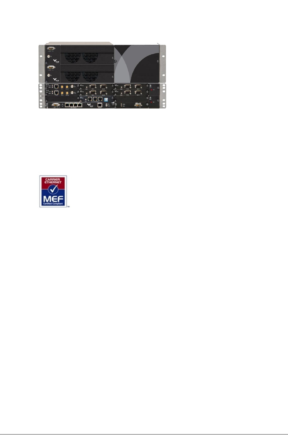
Figure 1. INUe with High-Power 3RU IRU 600
MEF Certified. Eclipse Node and Packet Node meet MEF 9 and MEF 14 requirements for
carrier-class Ethernet inter-operability and performance.
lMEF 9 specifies the User Network Interface (UNI)
lMEF 14 specifies Quality of Service (QoS)
Aviat Networks is ISO90001:2008 and TL9000 Certified. Full certification means all
departments and business units within Aviat Networks have been strictly assessed for
compliance to both standards. It testifies that Aviat Networks is a certified supplier of
products, services and solutions to the highest ISO and Telecommunication standards
available.
Node Indoor Units
There are two indoor units, the INU, and INUe (extended INU). The INU is a 1RU chassis, the
INUe 2RU chassis.
Mandatory plug-ins are the NCC (Node Control Card) and FAN (Fan card). The optional plug-
ins include RAC (Radio Access Card), DAC (Digital Access Card), AUX (Auxiliary), NPC (Node
Protection Card), and PCC (Power Converter Card).
INU
The INU requires one NCC and one FAN, and has provision for four option plug-ins. It
supports a maximum of three RFUs for three non-protected links, or one
protected/diversity link and one non-protected link.
AVIAT NETWORKS JULY 2018 41
CHAPTER 3SYSTEM OVERVIEW
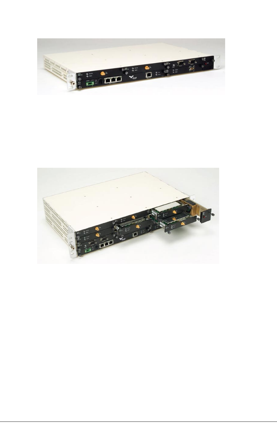
Figure 2. INU
INUe
The INUe requires one NCC and one 2RU FAN, and has provision for ten option cards. It
supports a maximum of six RFUs for six non-protected links, or up to three
protected/diversity links.
Figure 3. INUe
Plug-in Cards
Plug-in cards for the INU or INUe enable quick and easy customization on Eclipse
configurations. All cards are hot-pluggable.
RACs support the radio modem function. In the transmit direction they take the digital traffic
from the backplane or data packet plane and convert it to an IF signal for connection to an
RFU (ODU or IRU 600). The reverse occurs in the receive direction.
lOne RAC/ODU or RAC/IRU 600 combination is used for a 1+0 link.
lTwo RAC/ODUs or two RACs with one 1+1 IRU 600 are used for 1+1 hot-standby
or diversity links.
lRACs control TX switching and RX voting on protected / diversity links. Different
RACs support different capacity and modulation options.
42 JULY 2018 AVIAT NETWORKS

SYSTEM OVERVIEW CHAPTER 3
lXPIC (cross polarization interference cancellation) RACs support CCDP (co-
channel dual polarization) operation.
DACs support the user interface.
lDifferent DACs support Ethernet, E1/DS1, E3/DS3, and STM1/OC3 connections.
lMultiplexer DACs support transport of STM1/OC3 or E3/DS3 with NxE1/DS1
rates.
lEthernet DACs support a L2 switch function. DAC GE3 supports advanced options
for Synchronous Ethernet, ring/mesh protection, QoS, buffer management, link
aggregation, VLAN tagging, and OAM.
lMost DACs can be protected using a stacked (paired) configuration.
lE1/DS1, DS3, and STM1/OC3 DACs support Ethernet-over-TDM options to enable
Ethernet transport over legacy TDM radio or leased-line links.
NCM (Network Convergence Module) provides an E1/DS1 loopswitch capability.
AUX (Auxiliary card) supports async or sync service-channel connections, and alarm I/O
options for connection to external devices.
NCC (Node Controller Card) provides Node management and DC-DC converter functions.
NCC is a mandatory card.
lIt manages Node operation and event collection and management.
lIt incorporates a router function for local and remote network management
interconnection.
lNode configuration and licensing data is held in flash-memory.
lPower supply: -48 Vdc (SELV -40.5 to -60 Vdc).
FAN (Fan card) provides forced-air cooling. FAN is a mandatory card.
NPC (Node Protection Card) provides 1+1 protection functions for the NCC power supply and
backplane management.
PCC (Power Conversion Card) supports operation from a +24 Vdc power supply.
The figure below illustrates the nodal concept and the wide range of plug-in cards.
See Plug-in Cards Overview on page 43 for an introduction to the cards and their functions.
Plug-in Cards Overview
NOTE: RAC 60, RAC 6X, RAC 3X, RAC 30A, RAC 40, RAC 4X, DAC GE, DAC
ES, DAC 16x are legacy plug-ins - they are no longer manufactured.
NOTE: For more detailed information on plug-ins refer to the Eclipse
Platform Product Description.
AVIAT NETWORKS JULY 2018 43
CHAPTER 3SYSTEM OVERVIEW
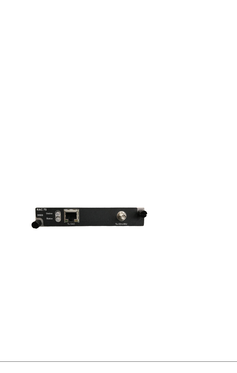
RAC 70
RAC 70 supports DPP (Data Packet Plane) and ACM (Adaptive Coding and Modulation)
options. RAC 70 additionally supports airlink recovered timing (ART) for high accuracy radio
transport of a SyncE clock.
There are ten dynamically switched modulation rates; QPSK, 16 QAM, 32 QAM, 64 QAM, 128
QAM, 256 QAM, 512 QAM, 1024 QAM, 2048 QAM and 4096 QAM, (2048 QAM and 4096 QAM
are only available with the ODU 600v2 or IRU 600v4).
lAll of the modulation states offered with ACM can be selected for use.
lModulation switching (state change) is errorless for priority traffic.
A DPP port enables direct routing of Ethernet traffic to a DAC GE3.
Payload encryption is a licensed option (this is the same license as for the RAC
60/6x/60E/6xE).
Individual ACM modulations can be set as fixed rates. These are complemented by fixed-
only rates for TDM capacities (DS1). DS3 and OC3 are not supported by the RAC 70.
Channel bandwidths range from 10 to 80 MHz ANSI. Air-link capacities for Ethernet, or for
Ethernet+TDM, extend to 715 Mbit/s. TDM options extend to 127xDS1.
ART operation is designed to meet G.8262 synchronization mask requirements for SyncE
clock transport.
RAC 70 interfaces to an ODU 600, or to the IRU 600.
Figure 4. RAC 70
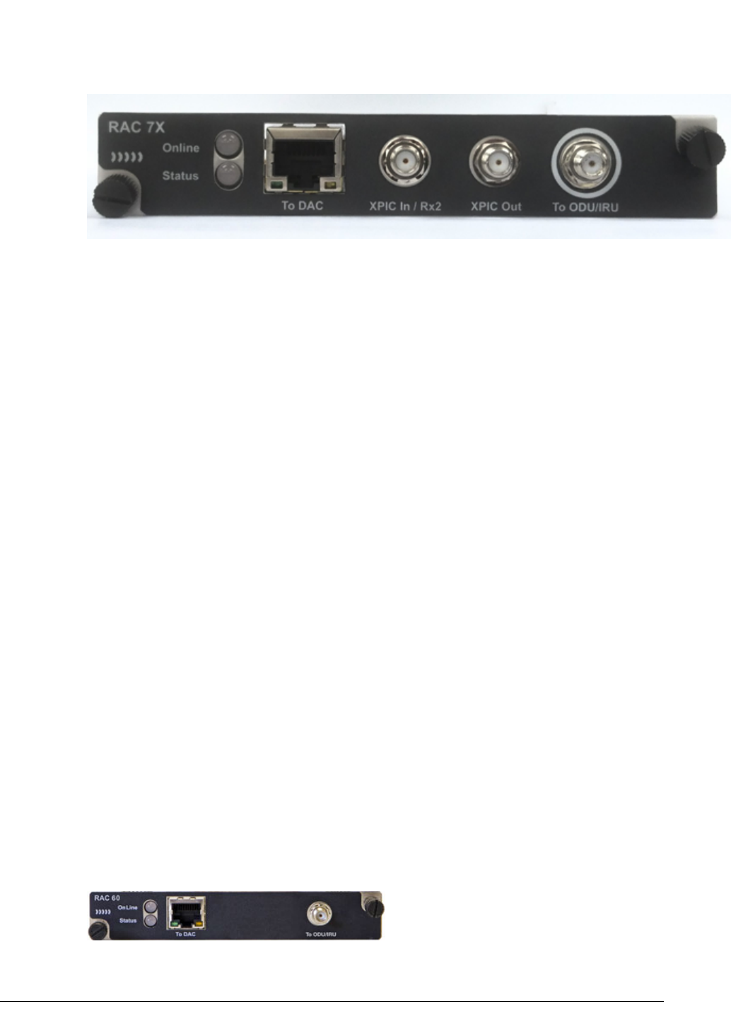
RAC7X
RAC 7X adds CCDP operation to RAC 70 capabilities.
Two RAC 7X cards are operated as a CCDP pair, either in the same INU, or in separate co-
located INUs to provide double the capacity over one channel, using both the horizontal and
vertical polarizations. An XPIC function between the RACs ensures cross-polarization
interference is eliminated.
44 JULY 2018 AVIAT NETWORKS
SYSTEM OVERVIEW CHAPTER 3
Figure 5. RAC 7X
RAC 60 and RAC 60E
RAC 60 supports DPP (Data Packet Plane) and ACM (Adaptive Coding and Modulation)
options. RAC 60E additionally supports airlink recovered timing (ART) for high accuracy
radio transport of a SyncE clock.
There are four dynamically switched modulation rates; QPSK, 16 QAM, 64 QAM, 256 QAM.
Coding options additionally apply on each of these modulations, one for maximum
throughput, one for maximum gain, to provide an effective total of eight modulation states.
lMaximum throughput delivers maximum data throughput - at the expense of some
system gain.
lMaximum gain delivers best system gain - at the expense of some throughput.
lUp to four of the eight modulation states offered with ACM can be selected for use.
lModulation switching (state change) is errorless for priority traffic.
A DPP port enables direct routing of Ethernet traffic to a DAC GE/GE3.
Individual ACM modulations can be set as fixed rates. These are complemented by fixed-
only rates for TDM capacities (E1/DS1, DS3, STM1/OC3) .
Channel bandwidths range from 5 to 56 MHz ETSI, and 3.5 to 80 MHz ANSI.
Air-link capacities for Ethernet, or for Ethernet+TDM, extend to 366 Mbit/s.
TDM options extend to 100xE1, 127xDS1, 4xDS3, 2xSTM1/OC3.
Payload encryption is a licensed option.
RAC 60E ART operation is designed to meet G.8262 synchronization mask requirements for
SyncE clock transport.
RAC 60/60E interfaces to an ODU 600, ODU 300hp, or to the IRU 600.
A RAC 60 can link to a RAC 6X in non-CCDP mode, or to a RAC 6XE in non-CCDP, non ART
modes.
Figure 6. RAC 60
AVIAT NETWORKS JULY 2018 45
CHAPTER 3SYSTEM OVERVIEW
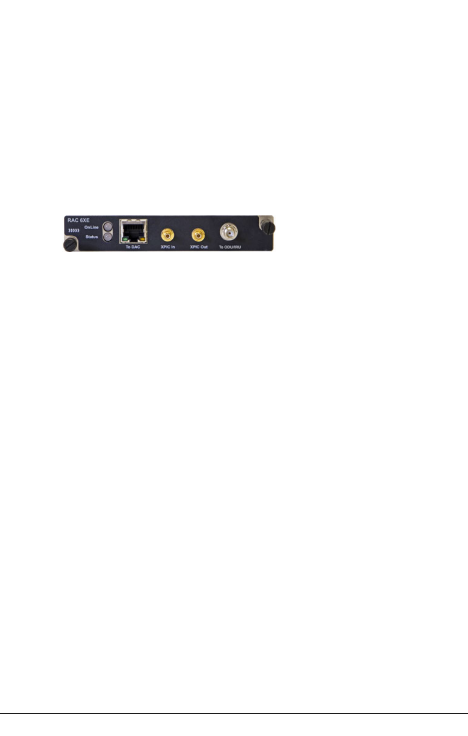
RAC 6X and RAC 6XE
RAC 6X/6XE adds CCDP operation to RAC 60/60E capabilities. RAC 6XE additionally supports
ART.
Two RAC 6X/6XE cards are operated as a CCDP pair, either in the same INU, or in separate
co-located INUs to provide double the capacity over one channel, using both the horizontal
and vertical polarizations. An XPIC function between the RACs ensures cross-polarization
interference is eliminated.
A RAC 6X can link to a RAC 6XE where ART capability is not required.
Figure 7. RAC 6XE
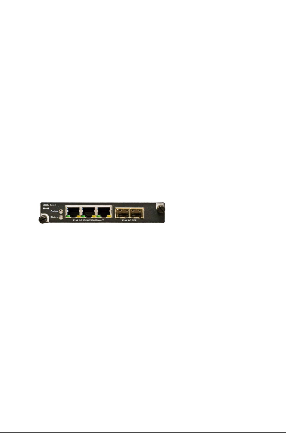
DAC GE3
DAC GE3 capabilities include Synchronous Ethernet, link aggregation, policing, ring/mesh
protection and Ethernet service OAM.
lThree RJ-45 10/100/1000Base-T ports
lTwo multi-purpose SFP ports with plug-ins for:
oOptical LC, 1000Base-LX, 1310 nm single-mode
oOptical LC, 1000Base-SX, 850 nm multi-mode
oElectrical RJ-45 10/100/1000Base-T
lSix transport channel (TC) ports
lComprehensive QoS traffic prioritization and scheduling options:
o802.1p mapping
oDiffServ mapping (IPv4, IPv6)
oMPLS Exp bits mapping
oStrict priority scheduling
oDeficit Weighted-Round-Robin (DWRR) scheduling
oHybrid strict + DWRR scheduling
oEight transmission queues
lTraffic policing using TrTCM (two rate, three color metering) with remarking
options
lL2 LAG (IEEE 802.1AX), static and LACP
lL1LA (Layer 1 link aggregation)
lAdvanced options for VLAN tagging, including Q (802.1Q), QinQ (802.1ad),
Filtering, Translation
46 JULY 2018 AVIAT NETWORKS
SYSTEM OVERVIEW CHAPTER 3
lSynchronous Ethernet with Stratum 3 hold-over performance on timing
subsystem
lRSTP (IEEE 802.1w)
lERP (ITU-T 8032v2)
lEthernet service OAM (IEEE 802.1ag/IYU-T Y.1731: ETH-CC, ETH-LB, ETH-LT)
lData packet plane (DPP) and/or backplane traffic interconnection to RACs
lAdvanced traffic shaping for fixed and adaptive modulation links
lSuperior burst management with 1500 Kbytes shared memory across active
ports
lStorm control
lJumbo frames to 10 Kbytes bi-directional
lFlow control (IEEE 802.3x)
l1+1 port and card protection
lInter-frame gap (IFG) and preamble stripping and re-insertion
lRMON stats per port, channel, and queue
lCompatibility with DAC GE, DAC ES, IDU ES, IDU GE 20x, IDU GE3 16x
Figure 8. DAC GE3
For DPP traffic a DAC GE3 must be operated with a RAC 70/7X, RAC 60/60E or RAC 6X/6XE.
RAC 60E/6XE/70/7X is required for Synchronous Ethernet links.
DAC GE
DAC GE interfaces three 10/100/1000Base-T electrical ports and one 1000Base-LX optical
port, to one or two transport channels. Features include:
lTraffic prioritization options
o802.1p mapping
oDiffServ mapping (IPv4)
oFour transmission queues
lTransparent, VLAN and mixed modes of operation
lEnhanced, fast-switched RSTP
lLayer 1 or Layer 2 link aggregation
lVLAN tagging, for Q and QinQ
lDPP and backplane traffic connections
lInter-frame gap (IFG) and preamble stripping and re-insertion
lFrame sizes to 9600 bytes
lAssignment to radio or fiber links
AVIAT NETWORKS JULY 2018 47
CHAPTER 3SYSTEM OVERVIEW
lSFP optical port options for 1310nm single-mode, or 850nm multi-mode
lCompatibility with DAC GE3, DAC ES, IDU ES, IDU GE 20x, IDU GE3 16x
Figure 9. DAC GE
For DPP traffic a DAC GE must be operated with a RAC 60/60E or RAC 6X/6XE.
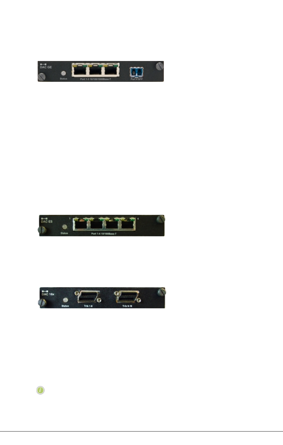
DAC ES
DAC ES interfaces four 10/100Base-T Ethernet ports to one or two radio and/or fiber
transport channels. Features include:
lAdvanced QoS settings
lTransparent, VLAN and mixed modes of operation.
lThroughputs to 100 Mbit/s per transport channel
lAssignment to radio or fiber links
lInter-frame gap (IFG) and preamble stripping and re-insertion
lCompatibility with DAC GE3, DAC GE, IDU ES, IDU GE 20x, IDU GE3 16x
Figure 10. DAC ES
DAC 16X
DAC 16x supports 16xE1 or 16xDS1 tributaries on Mini RJ-21 connectors.
Figure 11. DAC 16x
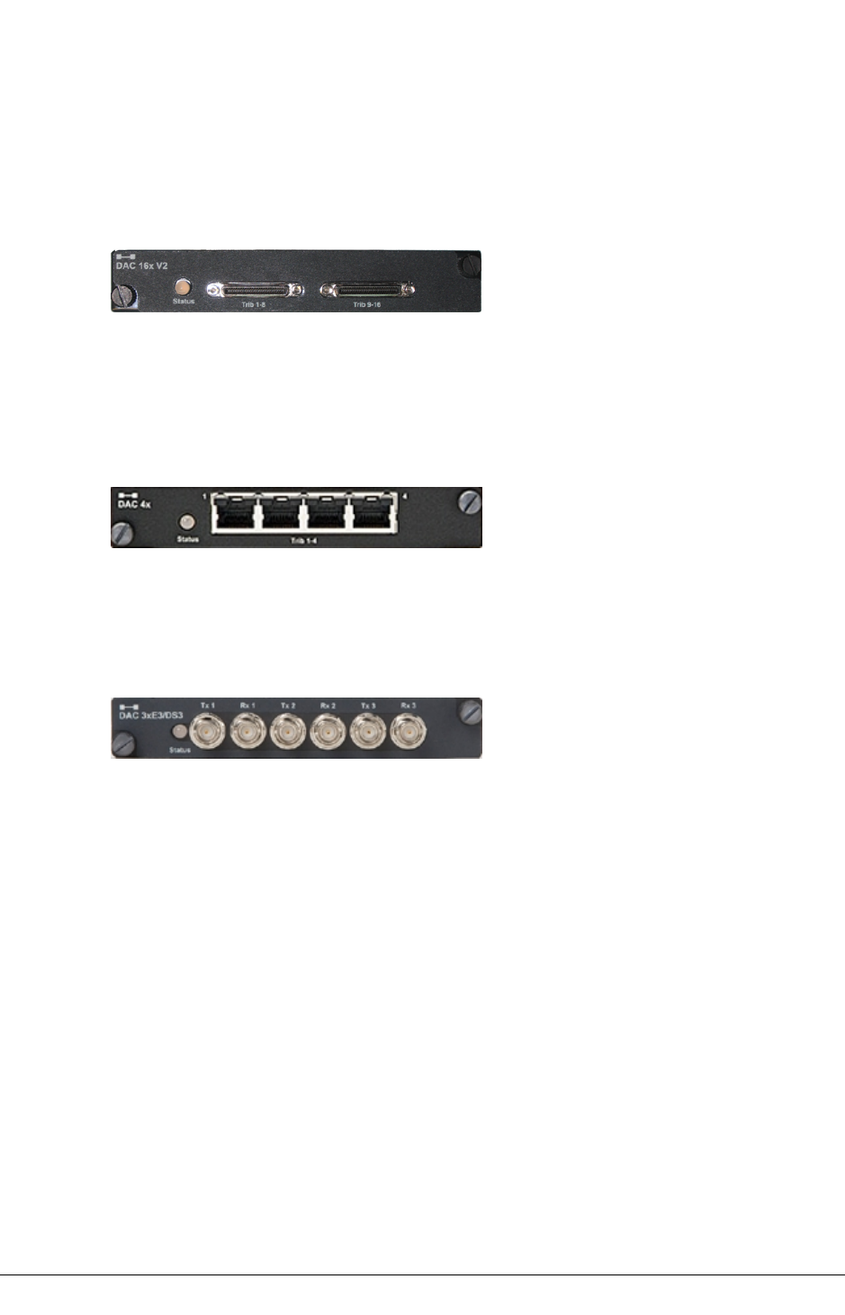
DAC 16xV2/V3
DAC 16xV2/V3 supports 16xE1 or 16xDS1 tributaries on compact HDR connectors.
The DAC 16xV3 is compatible with and can be safely used in all cases with the DAC 16xV2,
over the air, and in applications like NCM/SPDH/NTU, where a same DS1 can be inserted
via a DAC16Xv3 card(s) in one INU and then dropped on the facing side of the hop (or at an
INU further down in the network) via DACxV2 card(s), and vice-versa.
NOTE: An INU with a protected pair of DAC16xV3 cards can interface over
the air with an INU equipped with a protected pair DAC16xV2 to carry the
same DS1’s.
48 JULY 2018 AVIAT NETWORKS
SYSTEM OVERVIEW CHAPTER 3
Features additional to those provided by DAC 16x include:
lTributary protection
lEthernet over E1/DS1 tribs
lIndividual line code selection for AMI or B8ZS on DS1 tribs
Figure 12. DAC 16xV2
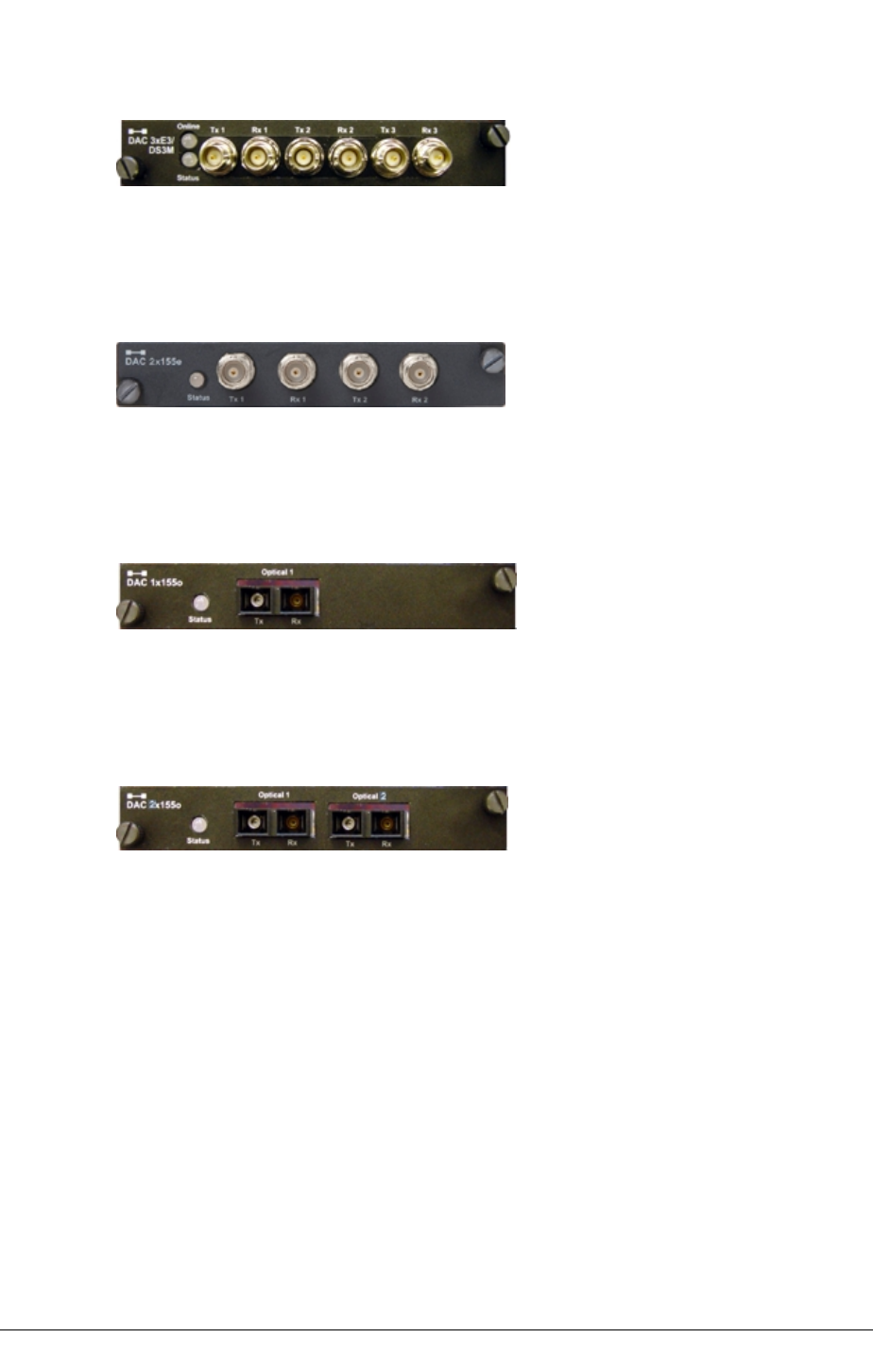
DAC 4X
DAC 4x supports 4xE1 or 4xDS1 tributaries on individual RJ-45 connectors. It also supports
E1 waysides on the STM1+1E1 link option.
Figure 13. DAC 4X
DAC 3xE3/DS3
DAC 3xE3/DS3 supports 3xE3 or 3xDS3 tributaries on paired mini-BNC connectors.
Figure 14. DAC 3xE3/DS3
DAC 3xE3/DS3M
DAC 3xE3/DS3M supports four operational modes:
lNormal E3/DS3 tributary operation (as for DAC 3xE3/DS3)
lE13 multiplexer mode. One or two E3 interfaces are multiplexed to an NxE1
backplane.
lM13 multiplexer mode. One or two DS3 interfaces are multiplexed to an NxDS1
backplane.
l34 Mbit/s transparent E3 mode for video (MPEG) transport. One or two
transparent E3 tributaries are each mapped to a 34xE1 backplane.
lDS3 Ethernet mode to enable up to 43 Mbit/s Ethernet over legacy TDM radio or
leased-line links (links must support transparent DS3).
Tribs are supported on paired mini-BNC connectors.
AVIAT NETWORKS JULY 2018 49
CHAPTER 3SYSTEM OVERVIEW
Figure 15. DAC 3xE3/DS3M
DAC 2x155e
DAC 2x155e supports two STM1 electrical tributaries on paired BNC connectors.
Figure 16. DAC 2x155e
DAC 1x155o
DAC 1x155o supports one STM1/OC3 single-mode optical tributary on SC connectors.
Figure 17. DAC 1x155o
DAC 2x155o
DAC 2x155o supports two STM1/OC3 single-mode optical tributaries on SC connectors.
Figure 18. DAC 2x155o
DAC 155oM
DAC 155oM multiplexes an STM1/OC3 optical tributary to an NxE1 or NxDS1 backplane. The
user interface is provided on an SFP optical transceiver. Different SFPs support 1310nm
single-mode, or 850nm multi-mode.
It functions as a terminal multiplexer; it terminates or originates the STM1/OC3 frame. It
does not support interconnection of ADMs as there is no provision to transport STM1/OC3
overheads for ADM to ADM synchronization.
In virtual tributary mode it transports up to 130 Mbit/s Ethernet over an STM1/OC3 link.
Options are provided for external/recovered, or internal clock sourcing.
50 JULY 2018 AVIAT NETWORKS
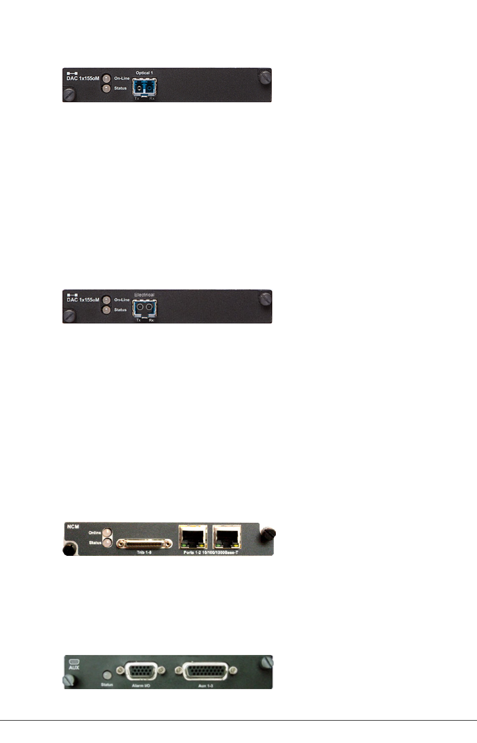
SYSTEM OVERVIEW CHAPTER 3
Figure 19. DAC 155oM
DAC 155eM
DAC 155eM multiplexes an STM1/OC3 electrical tributary to an NxE1 or NxDS1 backplane.
The user interface is provided on an SFP electrical transceiver.
It functions as a terminal multiplexer; it terminates or originates the STM1/OC3 frame. It
does not support interconnection of ADMs as there is no provision to transport STM1/OC3
overheads for ADM to ADM synchronization.
In virtual tributary mode it transports up to 130 Mbit/s Ethernet over an STM1/OC3 link.
Options are provided for external/recovered, or internal clock sourcing.
Figure 20. DAC 155oM
NCM
NCM provides an NxE1/DS1 loop switch capability. At ring nodes it is configured to access
redundant east and west traffic streams for data input (insert) and output (drop).
lTraffic inserted into a local tributary is transmitted on both east and west facing
streams to create a bi-directional ring.
lA local drop selection is made on these east and west streams on the receive
direction to use.
lOperation applies on either framed or unframed E1/DS1 tributaries.
lThe operational mode is low latency, non-hitless.
Figure 21. NCM
AUX
AUX provides synchronous and/or asynchronous auxiliary data channels, NMS porting, and
alarm input and output functions. Data options are sync at 64 kbps or async to 19.2 kbps.
Figure 22.
AVIAT NETWORKS JULY 2018 51
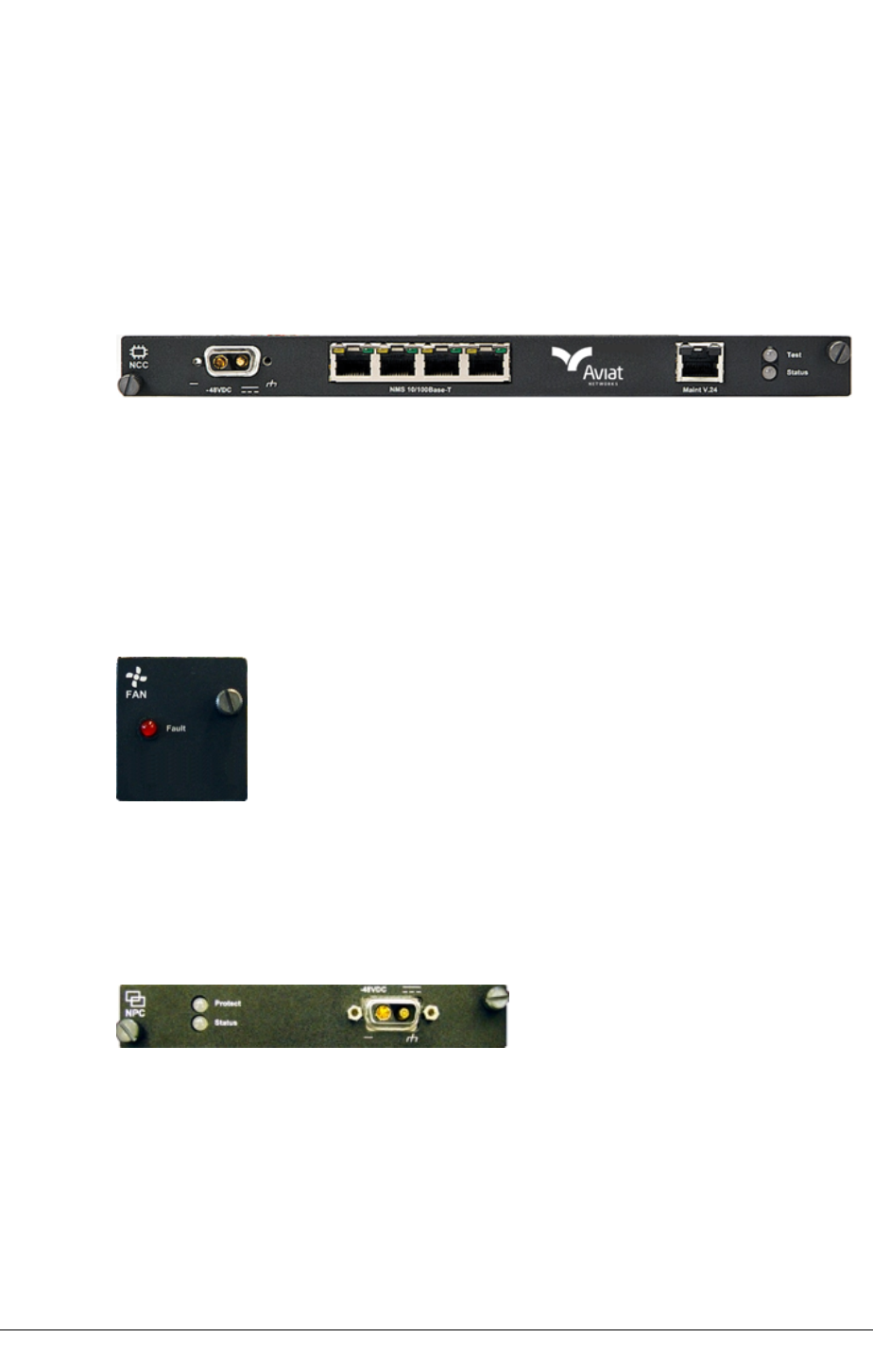
CHAPTER 3SYSTEM OVERVIEW
NCC
The NCC is a mandatory plug-in for an INU/INUe. It performs key node management and
control functions, and provides various dc rails from the -48 Vdc input. It also incorporates
a plug-in flash card, which holds Node configuration and license data.
Power input limits are -40.5 to -60 Vdc. The power connector is a D-Sub M/F 2W2. The
+ve dc return pin is connected to chassis ground.
Figure 23. NCC
FAN
The FAN is a mandatory plug-in. There are two variants, 2RU and 1RU. Each is fitted with
two long-life axial fans plus monitoring and control circuits.
One 1RU FAN is fitted in an INU.
One 2RU FAN or two 1RU FANs are fitted in the INUe. The 2RU FAN is standard.
Figure 24. FAN (1RU)
NPC
NPC provides redundancy for the NCC backplane bus management and power supply
functions.
Figure 25. NPC
PCC
The PCC provides a voltage conversion function for use at locations where the power supply
is +24 Vdc. It converts +24 (19 to 36) Vdc to -56 Vdc for connection to the INU -48Vdc input. -
56 Vdc represents the typical float voltage for a battery-backed -48 Vdc supply.
One PCC supports:
52 JULY 2018 AVIAT NETWORKS
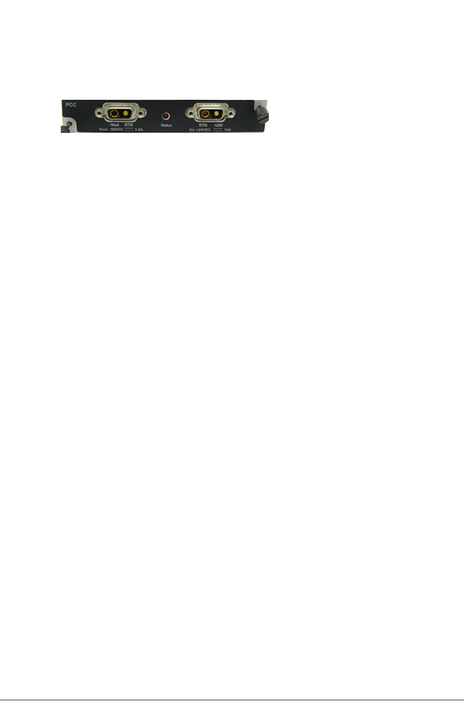
SYSTEM OVERVIEW CHAPTER 3
lUp to a 200W in air-conditioned installations (ambient max 250C / 770F).
lUp to a 150W in non-air-conditioned installations (ambient max 450C / 113oF).
Figure 26. PCC
Protection Options
The Nodes offer link, interface, network, and platform protection options:
Link/Path Protection
Hot-standby, space diversity, frequency diversity, or dual protection options are available.
All RACs and their companion ODU or IRU 600 are protectable.
RAC 70/7X does not support frequency diversity protection.
Rx path switching (voting) is hitless/errorless; Tx switching is not hitless.
A remote Tx switch is forced in the event of a silent Tx failure.
Interface Protection
Ethernet, E1/DS1, E3/DS3 and STM1/OC3 interfaces can be hot-standby protected using
paired (stacked) DACs.
The protectable DACs are DAC GE3, DAC 16x V2/V3, DAC E3/DS3, DAC 3xE3/DS3M, DAC
155o, DAC 2x155o, DAC 2x155e, DAC 155oM, DAC 155eM.
The NCM is also protectable using paired NCMs.
TDM Interfaces
For TDM DACs and for NCM front panel tributaries two interface protection configurations
are supported, tributary protection and always-on:
Tributary Protection
lY-cables connect the paired DACs/NCMs to customer equipment. (Y-cable
protection is not supported for DAC 155eM).
lIn the Rx direction (from the customer) both DACs/NCMs receive data, but only
the online Rx DAC/NCM sends this data to the backplane bus.
lIn the Tx direction, the online Tx DAC/NCM sends data to customer equipment, the
other mutes its Tx line interface.
lThe connected equipment is not involved in the protection process.
AVIAT NETWORKS JULY 2018 53

CHAPTER 3SYSTEM OVERVIEW
Tributary Always-On
lSeparate cables connect each DAC/NCM to customer equipment.
lIn the Rx direction (from the customer) both DACs/NCMs receive data, but only
the online Rx DAC/NCM sends this data to the backplane bus.
lIn the transmit direction both DACs/NCMs send data to customer equipment, and
the customer equipment switches between these two always-on tributaries.
lProtection switching is not hitless. Typical restoration times are between 80 ms
and 120 ms.
Network/Data Protection
Ethernet ring and ladder network protection is provided using RSTP or ERP options.
Ethernet data redundancy is provided on link-aggregated links using L1 or L2 options.
PDH ring network protection is provided using Eclipse E1/DS1 Loopswitch or Super PDH
(SPDHTM) configurations.
Ethernet Ring and Ladder Networks
Eclipse DAC GE3 supports two ring protection mechanisms, Ethernet Ring Protection (ERP,
ITU-T G.8032v2) and RSTP (IEEE 802.1w).
ERP is a fast-acting automatic protection switching (APS) protocol for Ethernet ring
topologies. Features include:
Ethernet Link Aggregation Protection
Traffic redundancy is supported on co-channel Ethernet links using L1 or L2 link
aggregation options. If one link fails, its traffic is recovered on the remaining link or links.
While the reduced bandwidth may result in some traffic loss for low-priority traffic,
appropriate QoS settings can be used to ensure security for all higher priority traffic.
Loop Switch Ring Protection
Loop switch operation employs the NCM for ring capacities to 50xE1 or 63xDS1, with traffic
switching at the local node level.
Operation is based on redundant east/west facing rings.
lTraffic inserted into a local tributary is transmitted in east and west directions to
create a bi-directional ring.
lAt a drop site traffic is selected from either the east or west direction. If the
selected direction fails, the opposite direction is automatically switched into
service.
lOne or more radio paths can be replaced by a fiber or coax span using the DAC
54 JULY 2018 AVIAT NETWORKS

SYSTEM OVERVIEW CHAPTER 3
155oM or DAC 3xE3/DS3M.
lThe operational mode is low latency, non-hitless.
Super PDH Ring Protection
Super PDHTM supports ring capacities to 64xE1 or 84xDS1, with traffic switching at the node
level using a ring wrapping technique.
Operation is based on east/west facing rings, one nominated as clockwise, the other anti-
clockwise.
lUnder normal no-fault conditions, all traffic is passed on the clockwise primary
ring.
lWhen a fault occurs, the secondary, anti-clockwise ring, provides the protection
capacity needed. Traffic is looped onto the secondary ring at one side of the break
point, and off at the other side, to bypass the break.
lOne or more radio paths can be replaced by a fiber span using the DAC 155oM.
lOperation is not hitless.
Platform Protection
Platform management functions provided by the NCC are protected using the NPC option to
protect essential backplane bus and power supply functions.
lBus protection protects all circuit/tributary traffic (alarm I/O is not protected).
lPower supply protection protects against an NCC power supply failure. If the NCC
converter or one of its supply rails fails, the NPC will take over without
interruption - and vice versa.
Eclipse Packet Node and Data Packet Plane
Data Packet Plane
DPP operation is enabled via direct cable connection between the front panel packet data
port on a RAC 70, RAC 60/60E, RAC 6X/6XE, and a front-panel port on a DAC GE3/GE.
Customer traffic connected to the DACs is bridged to the RACs, and then to the RF
transceiver; the split-mount ODU 300hp or ODU 600, or the all-indoor IRU 600.
Where required, customer data can also be sourced via the circuit-switched backplane,
meaning both the DPP and backplane can be used to source/send traffic. This has special
relevance where native mixed-mode IP + TDM traffic is to be sent over a Packet Node
wireless link; GigE IP traffic via the DPP, and TDM traffic via the backplane.
AVIAT NETWORKS JULY 2018 55

CHAPTER 3SYSTEM OVERVIEW
Advanced Adaptive Coding and Modulation (ACM)
Advanced ACM options are provided using RAC 70, RAC 60/60E or RAC 6X/6XE plug-ins.
lAdaptive modulation maximizes use of available channel bandwidth.
lCoding is used to extend throughput granularity by providing maximum throughput
or maximum system gain options on each adaptive modulation rate.
lACM operation requires a 2.048 or 1.544 Mbps Bus Connection Size.
RAC 70 Adaptive Modulation (AM)
AM uses one of ten automatically and dynamically switched modulations - QPSK, 16 QAM,
32 QAM, 64 QAM, 128 QAM, 256 QAM, 512 QAM, 1024 QAM, 2048 QAM or 4096 QAM. For a
given RF channel bandwidth a two-fold improvement in data throughput is provided for a
change from QPSK to 16 QAM, a three-fold improvement to 64 QAM, and a four-fold
improvement to 256 QAM.
The adaptive modulation engine ensures that the highest modulation and hence highest
throughput is always provided based on link quality.
Modulation switching is hitless/errorless.
Ethernet connections enjoy real synergy through the QoS awareness on the DAC GE3 GigE
switch, and the service provisioning provided by any MPLS or PBB-TE network overlay.
lAll high priority traffic, such as voice and video, continues to get through when
path conditions are poor and modulation/capacity is reduced.
lWhen path conditions are normal (good) best-effort lower priority traffic, such as
email and file transfers, enjoy data bandwidths that can be up to four times the
guaranteed (QPSK) bandwidth.
While adaptive modulation can also be used on PDH links and combined PDH and Ethernet
links, unlike Ethernet there is no QoS synergy on PDH connections.
lE1/DS1 connections are dropped in user-specified order when link capacity is
reduced, and restored when capacity is increased.
Coding
Modulation code options provide two sets of modulation states, one for maximum
throughput, the other for maximum gain. These apply on each of the modulation rates
(QPSK, 16 QAM, 64 QAM, 256 QAM) to provide a total of eight modulation states.
Maximum throughput delivers maximum data throughput - at the expense of some
system gain.
Maximum gain delivers best system gain - at the expense of some throughput.
56 JULY 2018 AVIAT NETWORKS

SYSTEM OVERVIEW CHAPTER 3
Up to four of the eight modulation states offered with ACM can be selected for use. For
example:
lWith four modulation rates, each can be set for maximum throughput or
maximum gain.
lWith three modulation rates, such as 16 QAM, 64 QAM, 256 QAM, one rate (any)
can be set for maximum gain and additionally for maximum throughput, to provide
four step AM operation.
lWith two modulation rates, such as 16 QAM (or 64 QAM) with 256 QAM, each can
be set for maximum gain and additionally for maximum throughput, to provide
four step AM operation.
This feature provides a practical trade-off between capacity and system gain to fine-tune
link performance. It provides best balance on AM operation.
lThe four modulation rates support near-linear 2x, 3x, 4x capacity steps.
lThe coding options allow capacity/gain variations on these rates to always support
up to four steps, even when just two of the possible four modulation rates are in
use, or are permitted.
lEven where just one modulation rate is required/permitted, the coding option
supports two-step AM operation, one for maximum throughput, one for maximum
gain.
Platforms
Eclipse supports flexible customization of traffic type, traffic capacity, and traffic protection
for up to three links using the INU, and to six links using the INUe.
For slot location and usage, cross-connects, capacity, and RAC/RFU parameters see:
Platform Layout on page 57
Slot Assignments on page 58
Platforms on page 57
Platform Layout
The following table lists INU and INUe platform support for:
lNon-protected and protected/diversity links
lSlot availability for option plug-ins
lOver-air data types supported
lODU and IRU 600 options
AVIAT NETWORKS JULY 2018 57
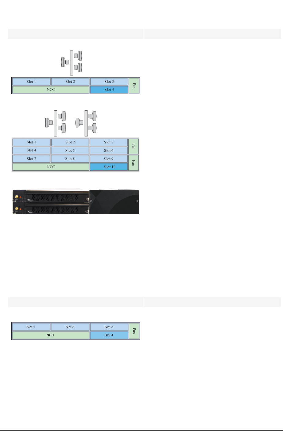
CHAPTER 3SYSTEM OVERVIEW
INU Supports 3 non-protected links or 1 protected/diversity
and 1 non-protected link.
INUe Supports up to 6 non-protected links for:
1 protected/diversity and 4 non-protected links, or
2 protected/diversity and 2 non-protected links, or
3 protected/diversity links.
IRU 600 IRU 600:
QPSK to 256 QAM, 4 to 11 GHz ANSI licensed bands,
5.8 GHz ISM band (USA and Canada).
Requires RAC 60/RAC 6X or RAC 60E/6XE. Fixed or
adaptive modulation rates.
1+1 optimized.
Extra-high Power, high-power, standard power RFU
options.
Three variants: V1, V2, V3. V1 and V2 are 3RU. V3 is
2RU. V2 and V3 incorporate a Tx coaxial switch for
HSB and MHSB/SD operation. (V1 is discontinued).
Slot Assignments
INU/INUe Slots
INU Slots 1, 2, 3, 4 are universal: any RAC, DAC, NCM, or
AUX plug-in
Slot 4 is NPC or universal: NPC or any RAC, DAC,
NCM, AUX
NCC and FAN slots are dedicated
For protected operation the RAC/RAC, RAC/DAC
155oM, NCM/NCM, or DAC/DAC pairings can be
installed in any of the universal slots
58 JULY 2018 AVIAT NETWORKS

SYSTEM OVERVIEW CHAPTER 3
INU/INUe Slots
INUe Slots 1, 2, 3, 4, 5, 6 are universal: any RAC, DAC,
NCM, or AUX plug-in
Slots 7, 8, 9 are restricted: any DAC, NCM, or AUX,
except DAC 155oM/eM and AUX where NMS access is
required1
Slot 10 is restricted: NPC option only
NCC and FAN slots are dedicated - the INUe is
supplied standard with a single 2RU FAN, though
accepts two 1RU FANs
RAC/RAC, or RAC/DAC 155oM/eM protected pairings
must be installed in the positions indicated by the
arrows
For protected DACs or NCMs, the protection
partners can be installed in slots 1 to 9, except for
the DAC 155oM/eM where NMS access is needed, in
which case install only in slots 1 to 6
1Internal (backplane bus) NMS access is only provided on slots 1 to 6. Do not install DAC
155oM, DAC 155eM, or AUX in slots 7 to 9 if an NMS connection is required in their
configuration.
AVIAT NETWORKS JULY 2018 59
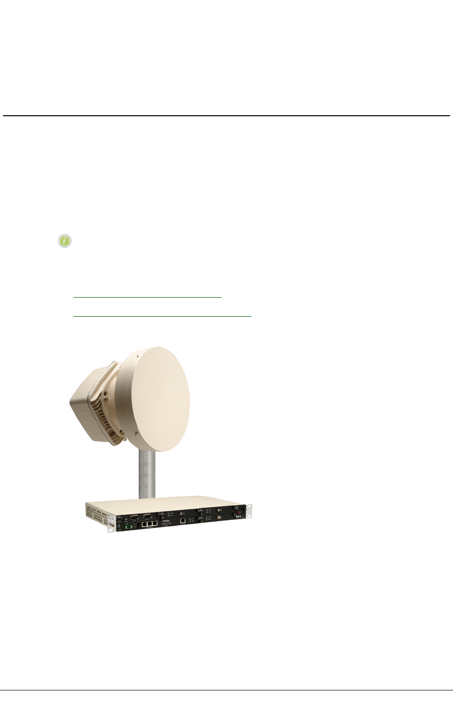
CHAPTER 3SYSTEM OVERVIEW
Eclipse Terminals
Eclipse Terminals (IDUs) are single-link radios. For network (multi-link) applications they
are back-to-back connected via their tributary ports at intermediate sites. Most can be
paired for protected link operation.
IDUs may also be over-air interfaced to like IDUs of higher or lower ultimate capacity and,
with the exception of the IDUsp, to Eclipse Node.
All IDUs support split-mount installation; only IDU GE3 16x supports split-mount or all-
indoor.
NOTE: All IDUs with the exception of IDU GE3 16x and IDU 155o are
legacy IDUs (no longer manufactured).
Refer to:
300 Series Indoor Units on page 60
Eclipse Radio Frequency Units on page 67
Figure 27. Eclipse Terminal
300 Series Indoor Units
IDU 300 variants support Ethernet, PDH, SDH, on ETSI and ANSI bands.
60 JULY 2018 AVIAT NETWORKS

SYSTEM OVERVIEW CHAPTER 3
Table 4. Current IDU 300 Variants
Application Variant Capacities Modulation
E1/DS1 only IDU 300
20xV2
5x, 10x, 20x, 32x, 40xE1, or
4x, 8x, 16x, 28x, 32xDS1
QPSK to 128QAM
IDUsp 4x 4xE1 QPSK
IDUsp 16x 4x, 8x, 16xE1 QPSK
STM1/OC3 IDU 155o STM1/OC3 16/64/128QAM
Ethernet with
E1/DS1
tributary options
IDU ES Airlink capacities to 200 Mbps with up to 8xE1/DS1
tribs.
Ethernet interfaces: 4x 10/100Base-T.
QPSK to 256QAM
IDU GE 20x Airlink capacities to 360 Mbps and up to 20xE1/DS1
tribs.
Ethernet interfaces: 2x 10/100/1000Base-T plus
2x SFP slots for 1000Base-LX optical 1310nm,
1000Base-SX optical 850nm, or 1000Base-T
electrical.
QPSK to 256QAM
IDU GE3 16x Airlink capacities to 366 Mbps and to 16xE1/DS1 tribs.
Ethernet interfaces: 4x 10/100/1000Base-T plus 2x SFP
slots for optical or electrical transceiver options.
QPSK to 256QAM with
fixed or adaptive
modulation
Split-mount ODU options support operation on bands 5 to 38 GHz.
All-indoor IRU 600 options support operation on ANSI bands L6 to 11 GHz, or 5.8 GHz
unlicensed band (USA and Canada only), with IDU GE3 16x only.
IDU 300 Series Overview
IDUs, except for IDUsp, can be over-air interfaced to an Eclipse Node. This applies only to
non-protected 1+0 link operation. Where 1+1 IDU operation is required, protected IDUs
must be installed at both link ends.
IDU GE3 16x
IDU GE3 16x is a state-of-art sub-compact radio terminal for all-IP and hybrid wireless
backhaul. Its internal modules comprise relevant RAC 60E, DAC GE3, DAC 16xV2, AUX and
NCC functions of Eclipse Node. Features include:
lSplit-mount with ODU 300 or ODU 600 on licensed bands 5 to 38 GHz
lAll-indoor with IRU 600 on ANSI licensed bands 4 to 11 GHz
lAll-indoor with IRU 600 on license-free 5.8 GHz ISM band (USA, Canada, only)
l256 QAM adaptive modulation
lExtensive IP traffic management and monitoring capabilities
lPacket-synchronization options
lFlexible IP or hybrid IP+PDH link operation
lBroad diagnostic functions
lSub-compact, 1/2RU rack-print
AVIAT NETWORKS JULY 2018 61

CHAPTER 3SYSTEM OVERVIEW
lLow power consumption (less than 30W) for simplified power supply and cooling
management
lAuxiliary data and alarm I/O options
lInter-operation with Eclipse Packet Node
lOptional NEBS compliance
RFU options are the ODU 300hp or ODU 300sp for split-mount operation, or the IRU 600 for
all-indoor.
Figure 28. IDU GE3 16x
Capacity is licensed. Feature licenses apply to adaptive modulation, synchronous Ethernet,
TDM tributary access, advanced QoS.
Adaptive or Fixed Modulation
Fixed and adaptive modulation options are available.
Adaptive modulation enables automatic adjustment of modulation and/or coding so that the
most data efficient (highest possible) modulation is used over the prevailing path conditions.
lAdaptive modulation refers to the dynamic adjustment of modulation rate.
lCoding refers to an ability to set individual modulation rates for maximum
throughput, or maximum system gain.
IDG GE3 supports four modulation rates, QPSK, 16 QAM, 64 QAM, or 256 QAM, plus a
coding option on each for a total of eight modulation states. Plus any of the modulation states
can be separately selected for fixed operation.
Hot Standby or Diversity Protection
Paired IDUs support 1+1 hot standby or space diversity operation.
Ethernet and E1/DS1 interface protection options are enabled with protected IDUs.
Carrier Class Ethernet Features
The Gigabit L2 switch capabilities include Synchronous Ethernet, 1+1 interface protection,
and superior packet buffering and queuing.
l6 user ports; 4x RJ-45; 2x SFP with optical or electrical transceiver options
l8 priority queues per port
l1+1 interface protection on protected IDUs
lPort and protocol-based priority assignment (MPLS Exp, DSCP, 802.1p)
lTrTCM traffic policing
lStrict, DWRR (Deficit Weighted Round Robin), and Hybrid scheduling modes
lVLAN tagging, untagging, filtering, and translation
lSynchronous Ethernet
62 JULY 2018 AVIAT NETWORKS
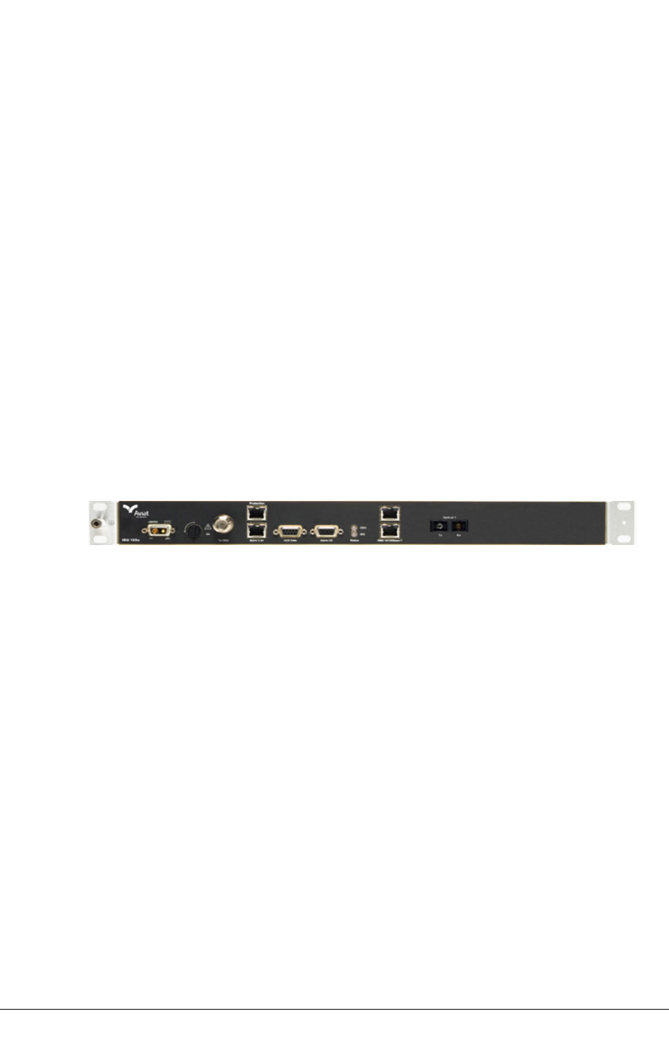
SYSTEM OVERVIEW CHAPTER 3
lLayer 2 link aggregation, IEEE 802.1AX static and dynamic (LACP)
lRing/mesh Protection, ERP (ITU-T G.8032v2) and RSTP (IEEE 802.1w)
lEthernet Service OAM (IEEE 802.1ag, and ITU-T under Y.1731)
lStorm control
lFlexible allocation of 1500 Kbytes of buffer memory.
lJumbo frames to 10 Kbytes bi-directional
lFlow control
lIFG and Preamble suppression
An IDU GE3 16x 1+0 terminal can be over-air interfaced to an Eclipse Packet Node
comprising the INU, RAC 60/60E, DAC GE3 (or DAC GE, DAC ES) with ODU 600, ODU 300hp
or IRU 600. Where E1 or DS1 side channels are required, a DAC 16xV2 should be installed in
the INU. Similarly an AUX is installed where external Alarm I/O interfaces are required.
For protected IDU GE3 16x operation, both ends of the link must be IDU GE3 16x.
IDU 155o
IDU 155o supports a single 155 Mbps STM1/OC3 tributary on optical SC connectors.
Modulations options are 16, 64 or 128 QAM.
Figure 29. IDU 155o
IDUs are paired to support 1+1 hot-standby or space diversity operation. Optical Y cables
are used to provide common Tx and Rx interfaces.
Tx switching is not hitless.
Rx switching (voting) is hitless (errorless).
Synchronous or asynchronous auxiliary data and alarm I/O options are included.
Requires ODU 300hp or ODU 300ep.
IDU 155o can be over-air interfaced to an Eclipse Node comprising the INU, DAC 155o,
2x155o, or 2x155e, and ODU 300. An AUX is installed where auxiliary channel services are
also required. This applies only to non-protected 1+0 link operation. Where 1+1 IDU
operation is required, protected IDUs must be installed at both link ends.
IDU300 20xV2
IDU 300 20xV2 supports 20 tributaries on individual RJ-45 connectors for E1 or DS1
operation, modulation options to 128 QAM, and over-air capacities to 40xE1 or 32xDS1.
Features include:
Capacities to 20xE1 / 16xDS1 for single link non-protected operation.
Capacities to 20xE1 or 16xDS1 for hot-standby or space diversity operation.
AVIAT NETWORKS JULY 2018 63
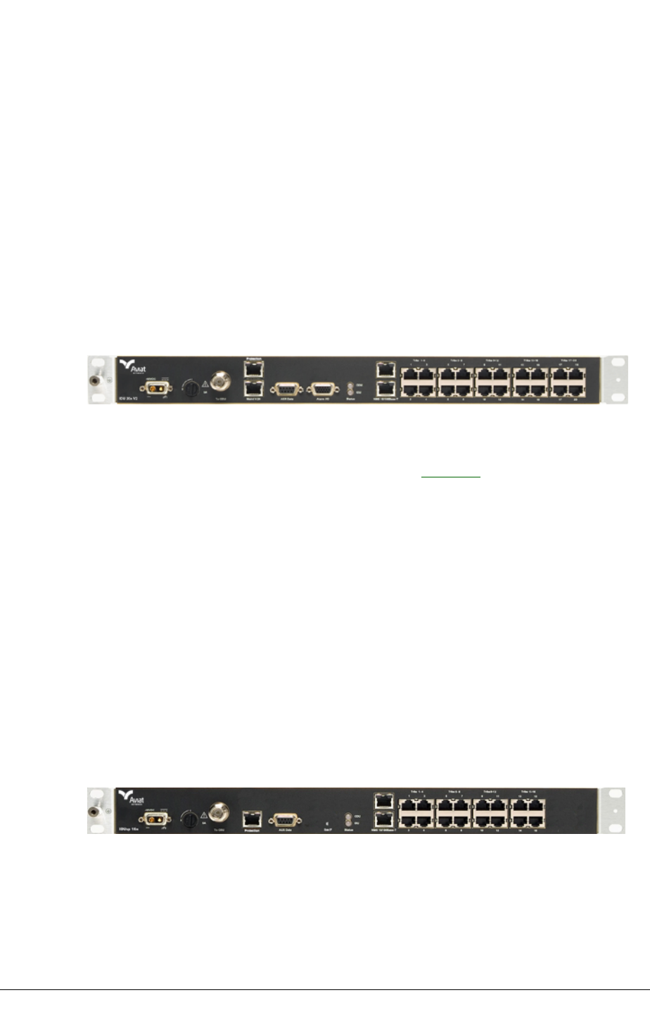
CHAPTER 3SYSTEM OVERVIEW
Capacities to 40xE1 or 32xDS1 for hot-standby operation.
IDUs are paired for protected/diversity operation.
For capacities to 20xE1 / 16xDS1 normal IDU equipment and path protection applies,
with Y cables used on the tribs.
For higher capacities, traffic from the standby IDU is routed to the online IDU to support
termination of up to 40xE1 or 32xDS1 tribs. In this configuration tributary and PSU
protection is not supported, however RAC/ODU and path protection functions are
retained.
Tx switching is not hitless.
Rx path switching (voting) is hitless (errorless) for capacities to 20xE1 /16xDS1. It is not
hitless when configured for 40xE1 / 32xDS1 operation.
Figure 30. IDU 300 20xV2
IDU 300 20xV2 is capacity licensed. The base configuration supports 20xE1/16xDS1, with
capacities to 40xE1 or 32xDS1 obtained by requesting additional capacity upgrades at time of
order or as field-downloadable software licenses. See Licensing.
Synchronous or asynchronous auxiliary data and alarm I/O options are included.
Requires ODU 300hp, ODU 300ep, or ODU 300sp.
IDU 300 20xV2 can be over-air interfaced to an Eclipse Node comprising the INU, DAC 16x
and ODU 300. An AUX is installed where auxiliary channel services are also required. This
applies only to non-protected 1+0 (20xE1 / 16xDS1 max) link operation. Where 1+1 IDU
operation is required, protected IDUs must be installed at both link ends.
IDUsp 16x and IDUsp 4x
These IDUs are cost optimized for basic E1 services:
IDUsp 4x: 4xE1 with QPSK modulation.
IDUsp 16x: 4x, 8x, 16xE1 with QPSK modulation.
Figure 31. IDUsp 16x
Paired IDUsp 16x IDUs support hot-standby operation; Tx and Rx switching is not hitless.
The IDUsp 4x is not protectable.
A single 64 kb synchronous auxiliary data connection is included; there is no alarm I/O.
IDUsp requires an ODU 300sp or ODU 300hp; ODU 300ep is not supported.
64 JULY 2018 AVIAT NETWORKS
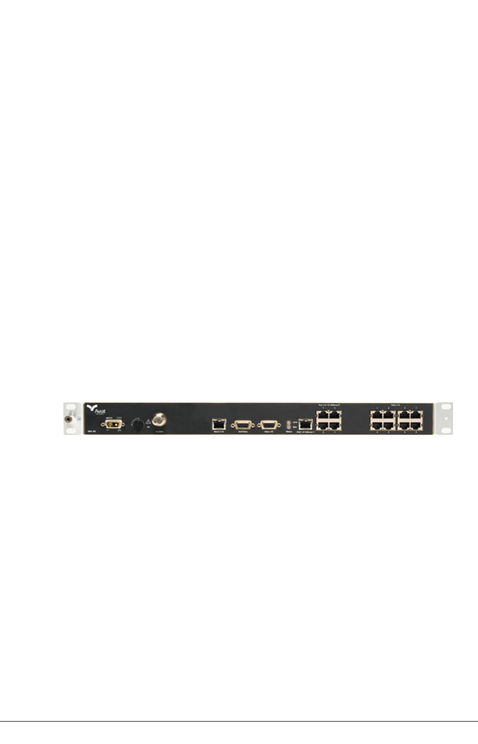
SYSTEM OVERVIEW CHAPTER 3
NMS connection is Ethernet-only; there is no serial interface for Portal PC connection.
Instead the IDU is configured as a DHCP (Dynamic Host Configuration Protocol) server and
the Portal PC as a client.
IDU ES
IDU ES supports Fast Ethernet to 200 Mbps to provide an uncomplicated and cost effective
alternative to fiber. Its Layer 2 switch supports four customer 10/100base-T ports, two
over-air transport channels and comprehensive QoS options.
Data throughput options range from 20 to 200 Mbps, and depending on the selected
throughput, channel bandwidth ranges from 7 to 56 MHz, with modulation options from
QPSK to 256 QAM.
Link capacity may be fully assigned to Ethernet traffic, or between Ethernet and up to 8
wayside E1/DS1 circuits.
Inter-frame gap (IFG) and preamble stripping and re-insertion is used across the link to
maximize Ethernet throughputs.
Capacity is licensed. The base configuration supports a 20 Mbps data throughput, with
higher capacities to 200 Mbps obtained by requesting additional capacity upgrades at time of
order, or as field-downloadable software licenses.
Protected 1+1 operation is not supported.
Figure 32. IDU ES
IDU ES is included in Aviat Networks’ Connect ES link package; a package comprising two
terminals, each with one IDU ES, and one ODU 300 outdoor unit, which depending on the
required throughput can be ODU 300sp, hp or ep.
Synchronous or asynchronous auxiliary data and alarm I/O options are included.
Requires ODU 300hp, ODU 300ep, or ODU 300sp.
IDU ES can be over-air interfaced to an Eclipse Node comprising the INU, DAC ES and ODU
300. Where E1/DS1 side channels are required a DAC 4x or DAC 16x is also installed.
Similarly an AUX is installed where auxiliary channel services are required.
IDU GE 20x
IDU GE 20x supports Gigabit Ethernet plus up to 20xE1 or 20xDS1 waysides.
Its Layer 2 switch supports two customer 10/100/1000base-T electrical ports, and an
optional SFP port for either 1000Base-X optical or 1000Base-T electrical. These interface to
one or two transport (link) channels using transparent, VLAN or mixed operational modes.
AVIAT NETWORKS JULY 2018 65
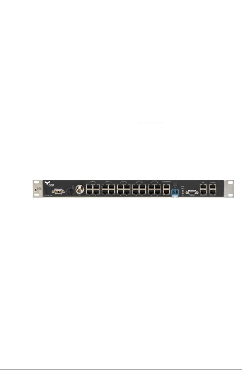
CHAPTER 3SYSTEM OVERVIEW
Switch features include RWPR (Resilient Wireless Packet Ring), layer 2 link aggregation,
and comprehensive QoS options with VLAN tagging and jumbo frame support.
Depending on the required Ethernet throughput, channel bandwidth ranges from 7 to 56 MHz
ETSI, and 5 to 80 MHz ANSI, with modulation options from QPSK to 256 QAM. Maximum
Ethernet throughput is 360 Mbps using one or both transport channels.
Configured link capacity may be assigned to Ethernet, or between Ethernet and up to 20xE1
or 20xDS1 side circuits, or to E1 or DS1 circuits only to a maximum of 20xE1 or 16xDS1.
Inter-frame gap (IFG) and preamble stripping and re-insertion is used to maximize data
throughput.
Capacity is licensed. The base configuration (no license required) supports 20xE1 or 20xDS1
circuits. The licensed extensions enable Ethernet in steps to 50, 100, 150, 200, or 360 Mbps,
each with up to 20xE1 or 20xDS1 waysides. See Licensing.
Protected 1+1 hot-standby or space diversity operation is configured by adding a second IDU
GE 20x. Ethernet traffic is supported on a single interface to one of the IDUs. E1/DS1 traffic
is supported on interfaces to both IDUs using Y-cables.
The 1RU IDU GE 20x complies with ETSI half-rack mechanical specifications with a rack
depth of 240 mm (9.4”).
Figure 33. IDU GE 20x
IDU GE 20x is also available in a ‘Connect’ link package, where a package comprises two
terminals, each with one IDU GE 20x, and one ODU 300 outdoor unit, which depending on the
required throughput and band, can be ODU 300sp, hp or ep.
Alarm I/O options are included.
An IDU GE 20x 1+0 terminal can be over-air interfaced to an Eclipse Node comprising the
INU, RAC 30 or RAC 3X, DAC GE or DAC ES, and ODU 300. Where E1 or DS1 side channels
are required, a DAC 4x or DAC 16x is also installed. Similarly an AUX is installed where
external Alarm I/O interfaces are required.
For protected IDU GE 20x operation, both ends of the link must be IDU GE 20x.
66 JULY 2018 AVIAT NETWORKS

SYSTEM OVERVIEW CHAPTER 3
Eclipse Radio Frequency Units
ODUs support split-mount installations. A rack-mounting IRU 600 is installed for all-indoor
installation.
IRU 600
The IRU 600 is a rack-mounted transceiver unit for co-location with an INU/INUe as an all-
indoor installation.
lIRU 600 is 1+1 optimized. It comprises one or two RFUs (radio frequency units),
and a filter-based ACU (antenna coupler unit).
oThe ACU design supports paired and unpaired Tx/Rx frequency splits and
incorporates an optional expansion port to allow other radio links onto its
waveguide feed for co-path operation.
oProtected/diversity options include:
n1+1 hot-standby
n1+0 hot-standby-ready
nSpace diversity (dual antennas) with common or split Tx
nFrequency diversity (single antenna) or frequency diversity with space
diversity (dual antennas)
o1+0 repeater (back-to-back) single chassis operation is supported. The links
may be in the same or different bands.
o2+0 (or 2+2 using dual IRU 600 chassis) single antenna.
lOperation encompasses ANSI 4/L6/U6/UU6, 7/8, 10, 11 GHz licensed bands, and
the FCC / Industry Canada 5.8 GHz unlicensed (ISM) band.
oIRU 600v2 has been supplied for the 4/L6/U6, 7/8, 10 and 11 GHz licensed
bands, and 5.8 GHz unlicensed band.
oWith the introduction of IRU 600v3/v4:
nIRU 600v3/v4 is supplied on bands 5.8, L6/U6/UU6, 11 GHz.
nIRU 600v2 is supplied on all bands 7/8, 10 GHz.
lFixed or adaptive modulation profiles are supported.
lIRU 600 is only supported from a RAC 70, RAC 60/6X, or RAC 60E/6XE.
lWhen multiple IRU 600 links are combined onto a single waveguide feed for ACCP
operation, required minimum Tx to Tx and Rx to Rx spacings, and minimum Tx to
Rx separations must be strictly maintained. For information on ACCP operation
AVIAT NETWORKS JULY 2018 67
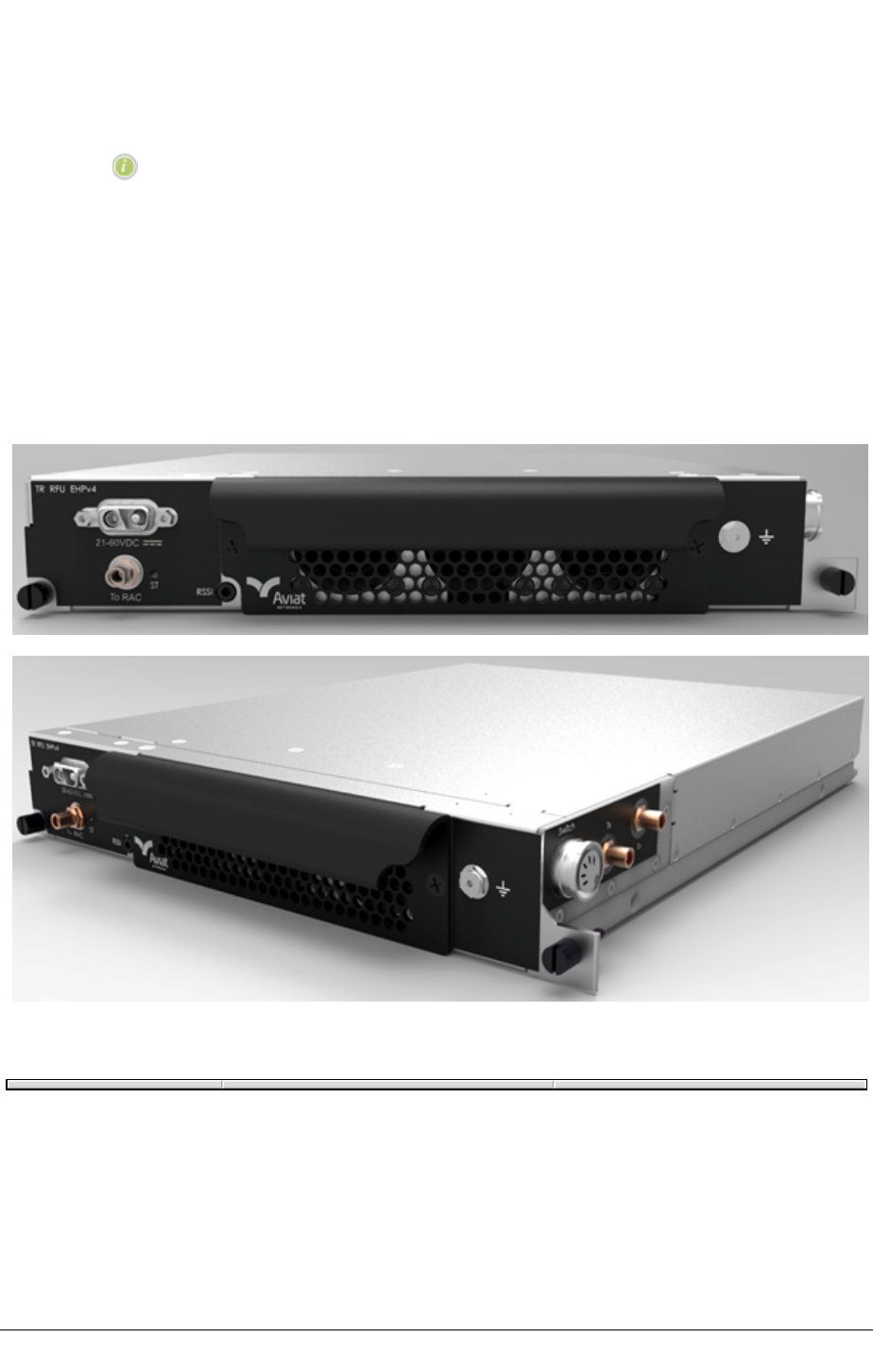
CHAPTER 3SYSTEM OVERVIEW
and limitations contact Aviat Networks or your supplier.
lEMI filtering is NEBS compliant.
NOTE: Unless otherwise stated, reference to IRU 600 refers to all IRU
600 variants.
IRU 600 Variants
There are four variants: IRU 600v4, IRU 600v3, IRU 600v2, IRU 600(v1). IRU 600(v1) is
discontinued.
IRU 600v4
Figure 34. IRU 600v4 Front and Side Views
IRU 600v4 is available with two RFU variants, one for Standard Tx power (SP) or High Tx
power (HP), and one for Extra High Tx power (EHP).
IRU 600v3/v4
IRU 600v3/v4 is available with two RFU variants, one for standard Tx power (Std) or high Tx
power (HP), and one for extra high Tx power (EHP).
68 JULY 2018 AVIAT NETWORKS

SYSTEM OVERVIEW CHAPTER 3
IRU 600v2 and IRU 600(v1)
Both support two RFU variants, a standard Tx power (Std) RFU, and a high Tx power (HP)
RFU.
Tx Coaxial Switch: IRU 600v4, IRU 600v3 and IRU 600v2
Primary benefits of the Tx coaxial switch are reduced power loss and faster Tx protection
switch times.
lIt avoids the losses associated with a Tx coupler/combiner.
oWith the Tx coaxial switch (relay) there is no A-side versus B-side
consideration required as the loss is not more than 0.5 dB on both. See ACU
Losses, IRU 600 on page 1.
lFor details on average recovery times, see Appendix G.
MHSB mode increases power consumption as both transmitters are fully active - both
online and offline Tx status is captured in real time. Where lower power consumption is the
priority, an option is provided to mute the offline Tx. For power consumption data See INU
Power Supply.
lWith MHSB operation both A-side and B-side transmit are fully monitored in real
time.
lWith a Tx mute configured on the offline Tx, its Tx status can be monitored though a
health monitoring facility whereby the Tx is turned on, checked and turned off
again. The turn-on period is adjustable between 0 (no health monitoring) and 240 in
1 hour increments.
lThe Mute Tx Offline selection is made in the RAC 70, RAC 60/60E/6x/6XE plug-ins
screen.
RFUs
RFUv4 (IRU 600v4)
lThere are two RFU variants, standard/high Tx power (SP/HP), and extra high Tx
power (EHP):
oAn HP feature license is required to enable high Tx power on the SP/HP RFU.
oNo feature license is required for the EHP RFU, the EHP capability is inclusive.
lThe DC supply for the SP/HP RFU is provided via the INU cable.
lThe EHP RFU is additionally powered via a front-panel D-Sub M/F 2W2 connector
for wide-mouth +/- 21 to 60 VDC supply. Both +ve and -ve pins are isolated from
ground.
oThe power connector (D-Sub M/F 2W2) and cable is identical to that used for
the INU.
oThe integral DC/DC converter provides polarity protection, under/over voltage
AVIAT NETWORKS JULY 2018 69

CHAPTER 3SYSTEM OVERVIEW
shutdown, over-current limit, and thermal shutdown.
oFor operation from +24 VDC supplies, the associated INU/INUe can be fitted
with a PCC to convert +24 VDC to - 48 VDC. Otherwise a suitable external
converter can be used - contact Aviat Networks for details.
lProtected operation for MHSB and MHSB/SD configurations uses a Tx coaxial
switch and an Rx coupler. Switch connection is via a DIN5 connector.
oThe DIN5 connector is located on the right side of the RFUs together with the
SMA connector for RF cable connection to the ACU/Coax switch.
lINU (RAC 70, RAC 60E/6XE) connection is via a front panel SMA connector. An
SMA-to-SMA cable is included with each RFU.
lRSSI access is provided on the front panel as meter test-probe points. Metal dot
on right of RFU for ground.
lThe RFU is 1RU, half-width.
lA front panel tri-color status LED indicates:
oRed flashing during boot-up
oGreen for normal operation
oRed when in an alarmed state
oOrange when in standby mode (standby Tx RFU in an MHSB or MHSB/SD
pairing)
lIncludes three software-controlled, individually alarmed, cooling fans.
RFUv3 (IRU 600v3/v4)
lThere are two RFU variants, standard/high Tx power (Std/HP), and extra high Tx
power (EHP):
oAn HP feature license is required to enable high Tx power on the Std/HP RFU.
oNo feature license is required for the EHP RFU, the EHP capability is inclusive.
lThe DC supply for the Std/HP RFU is provided via the INU cable.
lThe EHP RFU is additionally powered via a front-panel D-Sub M/F 2W2 connector
for wide-mouth +/- 21 to 60 Vdc supply. Both +ve and -ve pins are isolated from
ground.
oThe power connector (D-Sub M/F 2W2) and cable is identical to that used for
the INU.
oThe integral DC/DC converter provides polarity protection, under/over voltage
shutdown, over-current limit, and thermal shutdown.
oFor operation from +24 Vdc supplies, the associated INU/INUe can be fitted
with a PCC to convert +24 Vdc to - 48 Vdc. Otherwise a suitable external
converter can be used - contact Aviat Networks for details.
lProtected operation for HSB and HSB/SD configurations employs a Tx coaxial
switch and an Rx coupler. Switch connection is via a DIN5 connector.
70 JULY 2018 AVIAT NETWORKS

SYSTEM OVERVIEW CHAPTER 3
oThe DIN5 connector is located on the right side of the RFUs together with the
SMA connector for RF cable connection to the ACU/Coax switch.
lINU (RAC 70, RAC 60E/6XE) connection is via a front panel SMA connector. An
SMA-to-SMA cable is included with each RFU.
lRSSI access is provided on the front panel as meter test-probe points.
lPower consumption is reduced when Tx power output is lowered. Applies to both
ATPC and manual control of Tx power.
lThe RFU is 1RU, half-width.
lA front panel tri-color status LED indicates:
oRed flashing during boot-up
oGreen for normal operation
oRed when in an alarmed state
oOrange when in standby mode (standby Tx RFU in a HSB or HSB/SD pairing)
lIncludes four SW-controlled, individually alarmed, cooling fans.
RFUv2 (IRU 600v2)
lThe standard (Std) Tx power RFU is powered via its INU cable.
lThe high Tx power (HP) RFU is additionally powered via a front-panel D-Sub M/F
2W2 connector for wide-mouth +/- 21 to 60 Vdc supply. Both +ve and -ve pins are
isolated from ground.
oThe power connector (D-Sub M/F 2W2) and cable is identical to that used for
the INU.
oThe integral DC/DC converter provides polarity protection, under/over voltage
shutdown, over-current limit, and thermal shutdown.
oFor operation from +24 Vdc supplies, the associated INU/INUe can be fitted
with a PCC to convert +24 Vdc to - 48 Vdc. Otherwise a suitable external
converter can be used - contact Aviat Networks for details.
lProtected operation for HSB and HSB/SD configurations employs a Tx coaxial
switch and an Rx coupler. Switch connection is via a DIN5 connector.
oThe DIN5 connector is located on the right side of the RFUs together with the
SMA connector for RF cable connection to the ACU/Coax switch.
lINU (RAC 60E/6XE) connection is via a front panel SMA connector. An SMA-to-
SMA cable is included with each RFU.
lRSSI access is provided on the front panel as meter test-probe points.
lThe RFU is 1.5 RU, half-width.
lIncludes two cooling fans, individually alarmed.
AVIAT NETWORKS JULY 2018 71

CHAPTER 3SYSTEM OVERVIEW
IRU 600 Compatibility
IRU 600(v1) and IRU 600v2 share a common 3RU chassis. Dimensions and mounting points
for V1 and V2 RFUs and ACUs are identical.
IRU 600v3/v4 is housed in a compact 2RU chassis. While the ACU is unique to the V3, the V3
RFUs (Std/HP or EHP) can be used in V1 and V2 chassis using an adapter kit (Part No. 179-
530112-001).
The following use guidelines apply:
lV1 and V2 RFUs are compatible sparing partners EXCEPT for HSB configurations
where the ACU incorporates a coaxial relay Tx switch (IRU 600v2/v3 ACUs). RFU
V1 cannot control the Tx coaxial switch. This means that:
oV1, V2 RFUs are interchangeable for configurations not using a Tx switch eg.
FD, 2+0, SD split Tx, 1+0. Applies to V1 and V2 ACUs.
oIn protected HSB or HSB-ready systems with a V1 ACU (Tx combining), a V2
RFU can spare for a V1.
oOn V2 ACUs configured to use a Tx switch, the V1 RFU cannot spare for a V2
RFU.
oV2 HP RFUs require installation of a separate power supply connection (+/- 21
to 60 Vdc) to its front panel 2W2 power connector. A power cable is supplied
with the RFU.
lV3 RFUs can be installed in an IRU 600(v1) or IRU 600v2 chassis using an adapter
kit, which increases V3 RFU unit height to match the mounting points provided for
V1 and V2 RFUs.
oThe V3 RFU (with adapter kit installed) can be used in non-protected and
protected (HSB or HSB/SD) V1 and V2 chassis.
nIf installed in a V1 chassis Tx combining applies for HSB and HSB/SD
configurations.
nIf installed in a V2 chassis (with Tx protection switch) Tx switching applies
for HSB and HSB/SD configurations.
nIf a V3 Std/HP RFU is installed, an HP license must also be installed to
enable the high Tx power option on the RFU.
nIf a V3 EHP RFU is installed, a separate power supply connection (+/- 21 to
60 Vdc) to its front panel 2W2 power connector is required. A power cable
is supplied with the RFU.
oV1 or V2 RFUs cannot be installed in a V3 chassis.
lV1 and V2 ACUs are interchangeable. The V3 ACU is not.
oA V1 ACU can be installed in a V2 chassis, and vice-versa.
oV1 and V2 ACUs cannot be installed in a V3 chassis. Similarly a V3 ACU cannot
be installed in a V1 or V2 chassis.
72 JULY 2018 AVIAT NETWORKS

SYSTEM OVERVIEW CHAPTER 3
lAll IRUs are over-air compatible. For example, a 1+0 IRU 600(v1) may be linked
to a 1+0 IRU 600v2 or IRU 600v3. Similarly, 1+1 HSB IRU 600(v1) may be linked to
a 1+1 HSB IRU 600v2 or IRU 600v3. Hybrid configurations are also supported,
such as FD linked to SD split Tx.
IRU 600v1 and IRU 600v2 share a common 3 RU chassis. Dimensions and mounting points
for V1 and V2 RFUs and ACUs are identical.
IRU 600v3 and IRU 600v4 are housed in a compact 2 RU chassis. While the ACU is unique to
each of the V3 and V4, the V3 and V4 RFUs (SP/HP or EHP) can be used in V1 and V2 chassis
with existing v1 or v2 ACU using an adapter kit (Part N° 179- 530112-002) for V3 and (Part
179-530508-001) for V4.
The following use guidelines apply:
lV1 and V2 RFUs are compatible sparing partners EXCEPT for HSB configurations
where the ACU incorporates a coaxial relay Tx switch (IRU 600v2 ACUs). RFU V1
cannot control the Tx coaxial switch. This means that:
oV1, V2 RFUs are interchangeable for configurations not using a Tx switch eg.
FD, 2+0, SD split Tx, 1+0. Applies to V1 and V2 ACUs.
oIn protected HSB or HSB-ready systems with a V1 ACU (Tx using mute/unmute
instead of using an RF Tx switch), a V2 RFU can spare for a V1 by alternatively
using mute/unmute instead of attempting to control an RF Tx switch like a v2
RFU normally does.
oOn V2 ACUs configured to use a Tx switch, the V1 RFU cannot spare for a V2
RFU.
oV2 HP RFUs require installation of a separate power supply connection (+/- 21
to 60 Vdc) to its front panel 2W2 power connector. A power cable is supplied
with the RFU.
lV3 and V4 RFUs can be installed in an IRU 600v1 or IRU 600v2 chassis using an
adapter kit, which increases the V3 or V4 RFU unit height to match the mounting
points provided for V1 and V2 RFUs.
oThe V3 or V4 RFU (with adapter kit installed) can be used in non-protected and
protected (HSB or HSB/SD) V1 and V2 chassis.
lIf installed in a 3 RMS chassis equipped with a V1 RFU, Tx combining applies for
MHSB and MHSB/SD configurations.
lIf installed in a 3 RMS chassis equipped with a V2 RFU, (with Tx protection switch)
Tx switching applies for MHSB and MHSB/SD configurations.
lIf a V3 or V4 SP/HP RFU is installed, an HP license must also be installed to
enable the high Tx power option on the RFU.
lIf a V3 or V4 EHP RFU is installed, a separate power supply connection (+/- 21 to
60 VDC) to its front panel 2W2 power connector is required. A power cable is
supplied with the RFU.
lV1 or V2 RFUs cannot be installed in a V3 chassis.
AVIAT NETWORKS JULY 2018 73

CHAPTER 3SYSTEM OVERVIEW
lV1 and V2 ACUs are interchangeable. The V3 or V4 ACU is not.
oA V1 ACU can be installed in a V2 chassis, and vice-versa.
oV1 and V2 ACUs cannot be installed in a V3 or V4 chassis. Similarly, a V3 or V4
ACU cannot be installed in a V1 or V2 chassis.
lAll IRUs are over-air compatible when used with a same RAC on both sides of the
hop. For example, a 1+0 IRU 600v1 may be linked to a 1+0 IRU 600v2 or IRU
600v3, or IRU 600v4. Similarly, 1+1 HSB IRU 600v1 may be linked to a 1+1 HSB
IRU 600v2 or IRU 600v3, or IRU 600v4. Hybrid configurations are also supported,
such as FD linked to SD
5.8 GHz Unlicensed Band
The RFU for the 5.8 GHz unlicensed band is common to the L6 licensed band for easy
transition and sparing (from unlicensed to licensed and vice-versa). Links can be rapidly
deployed using 5.8 GHz unlicensed, and subsequently transitioned to L6 on license approval.
lThe RFU is a high-power (HP) variant
oWith IRU 600v2 the HP RFU is used.
oWith IRU 600v3 the Std/HP RFU is used (the V3 EHP RFU is not presently
available for use on the 5.8 GHz unlicensed band).
nTo operate the V3 Std/HP RFU at high Tx power, an HP license must be
installed.
lThe 5.8 GHz unlicensed band is designed to support easy and fast deployment.
With a suitable antenna, installation can be 'immediate'.
lThe common 5.8 GHz / L6 RFU design means subsequent conversion to L6
licensed operation only requires replacement of the ACU.
NOTE: 5.8 GHz operation supports fast turn-up for new link
requirements. On receipt of a license, operation can be converted to L6
licensed band by replacing the ACU.
Eclipse IDUs and INUs with IRU 600 are compliant with the relevant parts of FCC CFR47,
Part 15.407, and Industry Canada RSS-210 Annex 8, on ISM frequency band 5725 to 5850
MHz. International use is not supported; the system does not employ DFS and as such
cannot be deployed within Europe or any country where DFS is a regulatory requirement for
protection of radars.
Features and Capabilities:
lACU filters are tuned 30 MHz wide.
oFilters are spot tuned (pre-tuned) on 5740.5/5805.5 MHz or 5769.5/5834.5
MHz.
oWith 30 MHz filters just two Tx/Rx pairs can be used to provide full coverage of
the band.
74 JULY 2018 AVIAT NETWORKS

SYSTEM OVERVIEW CHAPTER 3
oOperation is designed to meet all regulatory requirements associated with 47
CFR Part 15.407. As such, deployment is precluded within 0.5 Mhz of the band
edges to comply with band edge emission requirements.
lBandwidths 5, 10, 20, or 30 MHz.
lTx and Rx can be paired on different sub-bands (Tx on one 30 MHz sub-band, RX on
the other).
lModulation can be adaptive (QPSK to 256 QAM), or fixed.
lSupports Ethernet and/or NxDS1, NxDS3, or OC3 payloads, with air-link
capacities to 189 Mbit/s (30 MHz Ch BW).
lThe common 5.8 GHz and L6 RFU supports easy migration from one band to the
other (from unlicensed to licensed and vice-versa).
oRFUs can be retained during migration, but ACU must be replaced (not re-
tuned).
lExtensive protection and diversity options.
lOutput power (at 5.8 GHz) is limited to 29 dBm at the antenna port to ensure
compliance with the FCC 1 Watt rule.
lFor Tx power, power control, and system gain figures, see the Eclipse Packet
Node ANSI Datasheet.
Operational Limitations and Restrictions
Unlicensed band operation means sharing the air-space with other operators of unlicensed
band links. interference is possible.
lIRU 600 5.8 GHz operation is narrow-band (max 30 MHz) high-power; it
competes/shares spectrum with other narrow-band links and with spread-
spectrum links.
lPerformance could deteriorate over time with the introduction of other links in the
same geographical area.
lAntennas must be approved (FCC or Industry Canada) for the 5.8 GHz unlicensed
band.
oEclipse 5.8 GHz is certified for use with a parabolic antenna with a maximum
gain of 45.9 dBi or a flat panel antenna with a maximum gain of 28 dBi.
AVIAT NETWORKS JULY 2018 75

CHAPTER 3SYSTEM OVERVIEW
Eclipse Licensing
Eclipse Node, IDU GE3 16x, IDU GE 20x, IDU ES, and IDU 300 20xV2 are subject to capacity
licensing. Eclipse Node and IDU GE3 16x are additionally subject to feature licensing on
advanced features.
Feature license operation is software release dependent. Ensure you have the relevant
software release installed. Refer to Licensing Requirements and Options on page 1.
INUs:
lFlexible Node-based Licensing applies for Eclipse Node and Packet Node to
replace/complement RAC-based licensing.
lNode-based licensing requires SW release 5.0 or later. (SW 5.0 or later must be
installed in a Node before installing or upgrading to Node-based licensing).
lNode-based licensing is required for DPP operation and for feature licensing.
lFeature Licensing applies on selected Node features. The licensed features are:
oEZF-01: Layer 1 Link Aggregation (DAC GE). Traffic is between the links on a
byte-by-byte basis, based on the capacity of the links. Unlike L2, it is fully
effective for just one active session, such as between routers, or where there
are only a few concurrent sessions.
oEZF-02: Adaptive Modulation (RAC 70, RAC 60/60E, RAC 6X/6XE). Packet Node
adaptive coding and modulation (ACM) dynamically switches between
modulation selections.QPSK, 16 QAM, 64 QAM, 256 QAM, 512 QAM, or 1024
QAM (2048 QAM, and 4096 QAM also on the RAC 70/7X). For the RAC
60/6X/60E/6XE, code settings additionally provide two sets of rates for each
modulation; one for maximum-throughput, the other for maximum-gain, to
provide eight modulation states in total.
oEZF-03: Secure Management (NMS). Applies to Eclipse NMS access over the
network, and to local access via the Portal craft tool. It also enables secure
management access to Eclipse over an unsecured network, and protects
Eclipse configurations from accidental or intentional modification by
unauthorized personnel.
oEZF-04: Payload Encryption (RAC 70, RAC 60/60E, 6X/6XE). Encrypts all traffic
and management data over the wireless link to prevent eavesdropping.
oEZF-05: Ethernet over TDM (DS3, E1, DS1). Enables mapping of Ethernet data
to DS3, E1, or DS1 PDH interfaces using the DAC 3xDS3M or DAC 16x V2/V3.
Supports transport of Ethernet data over existing DS3 or NxE1/DS1 radio or
leased-line circuits.
oEZF-06: RADIUS Client. Enables connection validation to a radius server for
76 JULY 2018 AVIAT NETWORKS

SYSTEM OVERVIEW CHAPTER 3
centralized account management.
oEZF-09: Synchronous Ethernet. Enables Synchronous Ethernet operation on
the DAC GE3.
oEZF-10: Ethernet OAM. Enables access to Ethernet Service OAM capabilities.
oEZF-14 and EZF-1408: TDM Loop Switch
nEZF-1408 supports up to 8xE1/DS1 circuits (the max number of
drop/insert tributaries supported on the NCM front panel).
nEZF-14 supports up to 50xE1 or 63xDS1 tributary circuits (the max number
of drop/insert tributaries supported on an INU/INUe - requires NCM
together with DXR 16xV2 plug-ins).
oEZF-42: FIPS 140-2 Secure Operation. Enables secure management of Eclipse
in compliance with the Federal Information Processing Standard (FIPS)
Publication 140-2. Applies to the INUe only.
oEZF-48: FIPS 140-2 + UC-APL Secure Operation. Enables secure management
of Eclipse in compliance with the Federal Information Processing Standard
(FIPS) Publication 140-2, also includes Unified Capabilities (UC) Approved
Products List (APL) compliance. Applies to the INUe only.
oEZF-43: Enables IPv6 operation. Includes OSPF IPv6 and RIPNG. Automatically
enabled in software 8.1 or later.
NOTE: When ODU 300 EP is present in the terminal, IPv4 address is
required for software loading.
oEZF-51 to EZF-56: ODU 600 high Tx power. Unlocks an additional 3dB of
transmit power over standard power. Applies to ODU 600 only, on all
modulations, on all bands. It also increases the manual and ATPC transmit
power control range by 3dB.
nEZF-51: ODU 600 High power option 1 x ODU
nEZF-52: ODU 600 Nodal High power option 2 x ODU
nEZF-53: ODU 600 Nodal High power option 3 x ODU
nEZF-54: ODU 600 Nodal High power option 4 x ODU
nEZF-55: ODU 600 Nodal High power option 5 x ODU
nEZF-56: ODU 600 Nodal High power option 6 x ODU
oEZF-61 to EZF-66: IRU 600v3/v4 high Tx power. Unlocks an additional 3dB of
transmit power over standard power. Applies on all modulations, on all IRU
600v3/v4 bands. It also increases the manual and ATPC transmit power
control range by 3dB.
nEZF-61 EZG-61 IRU 600 High power option 1 x RFU
nEZF-62 EZG-62 IRU 600 Nodal High power option 2 x RFU
nEZF-63 EZG-63 IRU 600 Nodal High power option 3 x RFU
nEZF-64 EZG-64 IRU 600 Nodal High power option 4 x RFU
AVIAT NETWORKS JULY 2018 77

CHAPTER 3SYSTEM OVERVIEW
nEZF-65 EZG-65 IRU 600 Nodal High power option 5 x RFU
nEZF-66 EZG-66 IRU 600 Nodal High power option 6 x RFU
lIDU licensing for all IDUs except IDU GE3 16x is unchanged.
NOTE: You can upgrade to SW release 5.0 or higher and still continue to
use RAC-based licensing but you will not have access to the benefits
provided under Node-based licensing (DPP operation and licensed
features).
All new Nodes ordered are default installed with the most recent SW
release version. From SW release 5.0, can elect to use (order) a Node-
based or RAC-based license.
IDU GE3 16x:
Capacity-based licensing and feature licensing applies on selected features.
Capacity Licenses:
lEZE-10020: 20 Mbit/s
lEZE-10050: 50 Mbit/s
lEZE-10100: 100 Mbit/s
lEZE-10150: 150 Mbit/s
lEZE-10200: 200 Mbit/s
lEZE-10400: 400 Mbit/s
Feature Licenses:
lEZF-10002: Adaptive Modulation
lEZF-10003: Secure Management
lEZF-10006: RADIUS
lEZF-10009: Synchronous Ethernet
lEZF-10010: Ethernet OAM
lEZF-10019: Enable TDM Ports
lEZF-10020: Advanced QoS
lEZF-10043: Enables IPv6 operation. Includes OSPF IPv6 and RIPNG.
Automatically enabled in software 8.1 or later.
NOTE: When ODU 300 EP is present in the terminal, IPv4 address is
required for software loading.
lEZF-10051: ODU 600 high Tx power option 1 x ODU. Unlocks an additional 3dB of
transmit power over standard power. Applies to ODU 600 only, on all
modulations, on all bands. It also increases the manual and ATPC transmit power
control range by 3dB.
lEZF-10061: IRU 600v3/v4 high Tx power option 1 x RFU. Unlocks an additional 3dB
of transmit power over standard power. Applies on all modulations, on all IRU
78 JULY 2018 AVIAT NETWORKS

SYSTEM OVERVIEW CHAPTER 3
600v3/v4 bands. It also increases the manual and ATPC transmit power control
range by 3dB.
AVIAT NETWORKS JULY 2018 79

CHAPTER 3SYSTEM OVERVIEW
Eclipse Configuration and Management
Eclipse is a software-driven product; there are no manual controls. Configuration and
management is achieved via Portal and ProVision.
Portal is a PC based configuration and diagnostics tool for Eclipse.
ProVision is the Eclipse network element manager. ProVision also supports other Aviat
Networks products, including legacy products.
Portal is supported in the Eclipse system software, such that once installed on a PC, it
automatically downloads support from the radio as needed to ensure Portal always
matches the version of system software supplied, or subsequently downloaded in any radio
upgrade.
Portal has the look and feel of a Windows environment with screen-based views and
prompts for all configuration and diagnostic attributes.
A Portal PC connects to an INU/INUe/IDU using Ethernet or V.24 options.
For more information see Introduction to Portal.
ProVision is the network element manager for all Aviat Networks radios (current and
legacy). ProVision also supports partner products, including multiplexors, switches,
routers, and power systems.
ProVision is installed on a Windows or Solaris server, typically at a network operating
center, and communicates with network elements using standard LAN/WAN IP addressing
and routing; each radio has its own unique IP address.
For more information about ProVision, refer to the Aviat Networks ProVision User Guide.
Secure Access from Portal and ProVision is enabled through the Secure Management and
RADIUS Client strong security options.
80 JULY 2018 AVIAT NETWORKS

SYSTEM OVERVIEW CHAPTER 3
Eclipse Antennas
Antennas for operation on the 5.8GHz unlicensed band are (must be) FCC approved.
lParabolic antennas for the 5.8 GHz unlicensed band must not exceed a maximum
gain of 45.9 dBi.
lFlat panel antennas for the 5.8 GHz unlicensed band must not exceed a maximum
gain of 28 dBi.
Antenna mounts are designed for use on industry-standard 115 mm OD (4.5 inch) pipe-
mounts.
AVIAT NETWORKS JULY 2018 81

CHAPTER 3SYSTEM OVERVIEW
Eclipse Power Supply
Eclipse is designed to operate from a -48Vdc power supply (+ve earth) but will operate to
specification over a voltage range of -40.5 to -60Vdc.
A plug-in PCC option for the INU provides a voltage conversion function for locations where
the power supply is +24 Vdc. It converts +24 (19 to 36) Vdc to -56 Vdc for connection to the
INU -48Vdc input. -56 Vdc represents the typical float voltage for a battery-backed -48 Vdc
supply.
The PCC supports:
lUp to a 200W in air-conditioned installations (ambient max 250C / 770F).
lUp to a 150W in non-air-conditioned installations (ambient max 450C / 113oF).
NOTE: An external +24 Vdc to -48 Vdc converter can be used instead of
the PCC. Contact Aviat Networks for details.
The dc power supply must be UL or IEC compliant for SELV (Safety Extra Low Voltage)
output (60Vdc maximum limited).
82 JULY 2018 AVIAT NETWORKS

INTRODUCTION TO ECLIPSE INSTALLATION CHAPTER 4
Chapter 4. Introduction to Eclipse Installation
This section covers installation procedures for Eclipse devices, from unpacking and
checking the equipment to completion of the physical installation and antenna alignment.
This section includes:
lInstallation Overview on page 84
lBefore Going On Site on page 85
For information on installing the Portal software to configure Eclipse, see Installing and
Connecting Portal on page 1.
NOTE: Eclipse has been tested for and meets EMC Directive 89/336/EEC.
The equipment was tested using screened cable; if any other type of
cable is used, it may violate compliance.
CAUTION: Eclipse is a Class A product. In a domestic environment it may cause radio
interference: be prepared to resolve this. Eclipse equipment is intended to be used
exclusively in telecommunications centers.
WARNING: You must comply with the relevant health and safety practices when
working on or around Eclipse radio equipment. Refer to the section on Health and
Safety on page 25.
AVIAT NETWORKS JULY 2018 83

CHAPTER 4INTRODUCTION TO ECLIPSE INSTALLATION
Installation Overview
This section provides a basic guide, in order, of an Eclipse hardware installation process.
Installation can be completed up to antenna alignment without the use of Eclipse Portal, the
PC based craft tool. Portal is required to check and configure an Eclipse Node or Terminal.
Hardware installation typically proceeds as follows:
1. Pre-Installation
lUnpack equipment - see Unpacking the Eclipse Equipment on page 86
lVerify system configuration:
lCheck basic components
lCheck kits and accessories
2. Installation
lAntenna - see See "Installing the Antenna"
lODU - see ODU Installation on page 1
lIRU 600 - see IRU 600 Installation on page 87
lINU / IDU chassis - see Installing the INU and INUe on page 101 or See "Installing
the IDU".
lINU plug-in cards - see Plug-in Installation Requirements on page 121
lTraffic and NMS cables - as required
84 JULY 2018 AVIAT NETWORKS

INTRODUCTION TO ECLIPSE INSTALLATION CHAPTER 4
Before Going On Site
This section includes:
lInstallation Tools and Materials on page 85
lUnpacking the Eclipse Equipment on page 86
Installation Tools and Materials
Ensure you have the following tools and material before going to site. These are items to be
sourced/supplied by the installer.
The items are indicative for standard installations. For non-standard installations additional
materials and tools may be required.
Table 5. Required Tools and Material
Equipment Tool/Material Description
Antenna As required by the
manufacturer
Refer to the manufacturer’s data supplied with each antenna
for required and recommended installation tools and
equipment. (Aviat Networks offers antennas from several
suppliers).
Eclipse Radios Basic electrician’s toolkit The kit must include a crimp lugs, a crimp tool for attaching
the lugs to stranded copper cable, a multimeter, and for ODU
polarization rotator bolts, a set of metric Allen keys.
Open-ended spanners 19mm (3/4 inch) open-ended spanner for attaching the ODU
to the mounting collar.
Torque wrench Capable of 66 N-m or 50 ft-lb, with a selection of sockets for
antenna mount fastening
Crimp tool(s) for ODU
cable connectors
The correct crimp and cut-off tools must be used to avoid
damage to the cable outer and to ensure correct crimping of
the connectors.
Hot-air gun For use on the heat-shrink tubing that may be supplied with
some brands of TypeN connector.
Protective grease and
zinc-rich paint
For weather-protecting grounding attachment points on
towers and grounding bars.
BNC cable To access the RSSI voltage at the ODU for antenna alignment.
This could be a BNC to banana-plugs cable for connection to a
multimeter. Such a cable is available as an optional accessory
Refer to Accessories in the Eclipse Product Ordering Guide.
4mm2(#12) green PVC
insulated strand copper
wire and grounding lugs
For grounding the indoor unit to the rack/frame
16 mm2(#6) green PVC
insulated strand copper
wire and grounding lugs
For grounding the rack to the station ground.
16mm is also required for chassis grounding for NEBS
compliance.
AVIAT NETWORKS JULY 2018 85

CHAPTER 4INTRODUCTION TO ECLIPSE INSTALLATION
Unpacking the Eclipse Equipment
To unpack Eclipse equipment:
1. Open the shipping boxes, carefully remove the equipment and place it on a clean, flat
working surface.
2. Ensure all the basic components and accessories for your system have been included
in the shipment by comparing the packaging, component part numbers and product
descriptions against the packing list, and cross-checking against the installation
datapack for the system to be installed.
3. If there has been shipping damage or there are discrepancies between the equipment
expected and the equipment received, contact an Aviat Networks Help Desk or your
supplier.
86 JULY 2018 AVIAT NETWORKS

IRU 600 INSTALLATION CHAPTER 5
Chapter 5. IRU 600 Installation
NOTE: Before commissioning an IRU 600 and companion INU, its
antenna, waveguide, and waveguide pressurization equipment must
be installed according to manufacturer’s instructions.
For an overview of IRU 600 features and function, see IRU 600 on page 67.
For information on installing an INU, see Installing the INU and INUe on page 101.
For guidance on installing antennas, waveguide, and pressurization equipment, see the Best
Practices Guide from Aviat Networks.
IRU 600 (v1), IRU 600v2, and IRU 600v3/v4 RFU Sparing Compatibility
For information on sparing compatibility see IRU 600 Compatibility on page 72.
AVIAT NETWORKS JULY 2018 87

CHAPTER 5IRU 600 INSTALLATION
IRU 600 Compatibility
IRU 600v1 and IRU 600v2 share a common 3 RU chassis. Dimensions and mounting points
for V1 and V2 RFUs and ACUs are identical.
IRU 600v3 and IRU 600v4 are housed in a compact 2 RU chassis. While the ACU is unique to
each of the V3 and V4, the V3 and V4 RFUs (SP/HP or EHP) can be used in V1 and V2 chassis
with existing v1 or v2 ACU using an adapter kit (Part N° 179-530112-002) for V3 and (Part N°
179-530508-001) for V4.
The following use guidelines apply:
lV1 and V2 RFUs are compatible sparing partners EXCEPT for HSB configurations
where the ACU incorporates a coaxial relay Tx switch (IRU 600v2 ACUs). RFU V1
cannot control the Tx coaxial switch. This means that:
oV1, V2 RFUs are interchangeable for configurations not using a Tx switch e.g.
FD, 2+0, SD split Tx, 1+0. Applies to V1 and V2 ACUs.
oIn protected HSB or HSB-ready systems with a V1 ACU (Tx using mute/unmute
instead of using an RF Tx switch), a V2 RFU can spare for a V1 by alternatively
using mute/unmute instead of attempting to control an RF Tx switch like a v2
RFU normally does.
oOn V2 ACUs configured to use a Tx switch, the V1 RFU cannot spare for a V2
RFU.
oV2 HP RFUs require installation of a separate power supply connection (+/- 21
to 60 Vdc) to its front panel 2W2 power connector. A power cable is supplied
with the RFU.
lV3 and V4 RFUs can be installed in an IRU 600v1 or IRU 600v2 chassis using an
adapter kit, which increases the V3 or V4 RFU unit height to match the mounting
points provided for V1 and V2 RFUs.
oThe V3 or V4 RFU (with adapter kit installed) can be used in non-protected and
protected (HSB or HSB/SD) V1 and V2 chassis.
lIf installed in a 3 RMS chassis equipped with a V1 RFU, Tx combining applies for
MHSB and MHSB/SD configurations.
lIf installed in a 3 RMS chassis equipped with a V2 RFU, (with Tx protection switch)
lTx switching applies for MHSB and MHSB/SD configurations.
lIf a V3 or V4 SP/HP RFU is installed, an HP license must also be installed to
enable the high Tx power option on the RFU.
lIf a V3 or V4 EHP RFU is installed, a separate power supply connection (+/- 21 to
60 VDC) to its front panel 2W2 power connector is required. A power cable is
supplied with the RFU.
88 JULY 2018 AVIAT NETWORKS

IRU 600 INSTALLATION CHAPTER 5
lV1 or V2 RFUs cannot be installed in a V3 chassis.
lV1 and V2 ACUs are interchangeable. The V3 or V4 ACU is not.
oA V1 ACU can be installed in a V2 chassis, and vice-versa.
oV1 and V2 ACUs cannot be installed in a V3 or V4 chassis. Similarly, a V3 or V4
ACU cannot be installed in a V1 or V2 chassis.
lAll IRUs are over-air compatible when used with a same RAC on both sides of the
hop.
oFor example, a 1+0 IRU 600v1 may be linked to a 1+0 IRU 600v2 or IRU 600v3,
or IRU 600v4. Similarly, 1+1 HSB IRU 600v1 may be linked to a 1+1 HSB IRU
600v2 or IRU 600v3, or IRU 600v4. Hybrid configurations are also supported,
such as FD linked to SD.
Table 6. RAC Compatibility Over-Air Links Guidelines and Examples:
IRU 600 RAC Link Direction IRU 600 RAC
V3 or V4 60/6X Same V4 or V3 60/6X
V4 or V3 70/7X Same V3 or V4 70/7X
V3 or V4 60/6X Independent V4 or V3 70/7X
V4 or V3 70/7X Independent V3 or V4 60/6X
AVIAT NETWORKS JULY 2018 89

CHAPTER 5IRU 600 INSTALLATION
IRU 600 Installation Procedure
This procedure applies to IRU 600v4, IRU 600v3, IRU 600v2, and IRU 600(v1).
lUnless otherwise stated, reference to IRU 600 refers to all IRU 600 variants.
lUnless otherwise stated, reference to a V2 RFU refers to standard power (Std)
and high-power (HP) variants.
lUnless otherwise stated, reference to a V3/V4 RFU refers to standard power
(Std), high-power (HP), and extra high-power (EHP) variants.
The IRU 600v3/v4 Std/HP RFU is SW configured for standard or high-power. The HP option
requires installation of HP feature license EZF-61 to 66, or EZG-61 to 66. See Node Feature
Licensing on page 1.
See:
lChassis Installation on page 90
lChassis Grounding on page 93
lWaveguide Installation on page 94
lWaveguide Connection to ACU on page 94
lPower Supply Connection on page 95
lInsertion Loss Labels on page 97
lIRU 600 Installation on page 87
lExpansion Port Use on page 97
lFAN Module on page 97
lIRU 600 Installation on page 87
lChassis Adapter Kit for IRU 600v3 and IRU 600v4 RFUs on page 98Chassis
Adapter Kit for IRU 600v3 and IRU 600v4 RFUs on page 98Chassis Adapter Kit for
IRU 600v3 and IRU 600v4 RFUs on page 98
Chassis Installation
1. Fit the rack mounting brackets onto the chassis.
oBrackets can be mounted in either a forward mount or a flush mount position.
oBrackets can be mounted such that the grounding stud is to the left or right
side.
2. Install the chassis. If installing multiple chassis:
oFor IRU 600(v1) and IRU 600v2 install with a 3RU space between the chassis to
permit installation of an expansion or extension kit. This space can be used to
90 JULY 2018 AVIAT NETWORKS
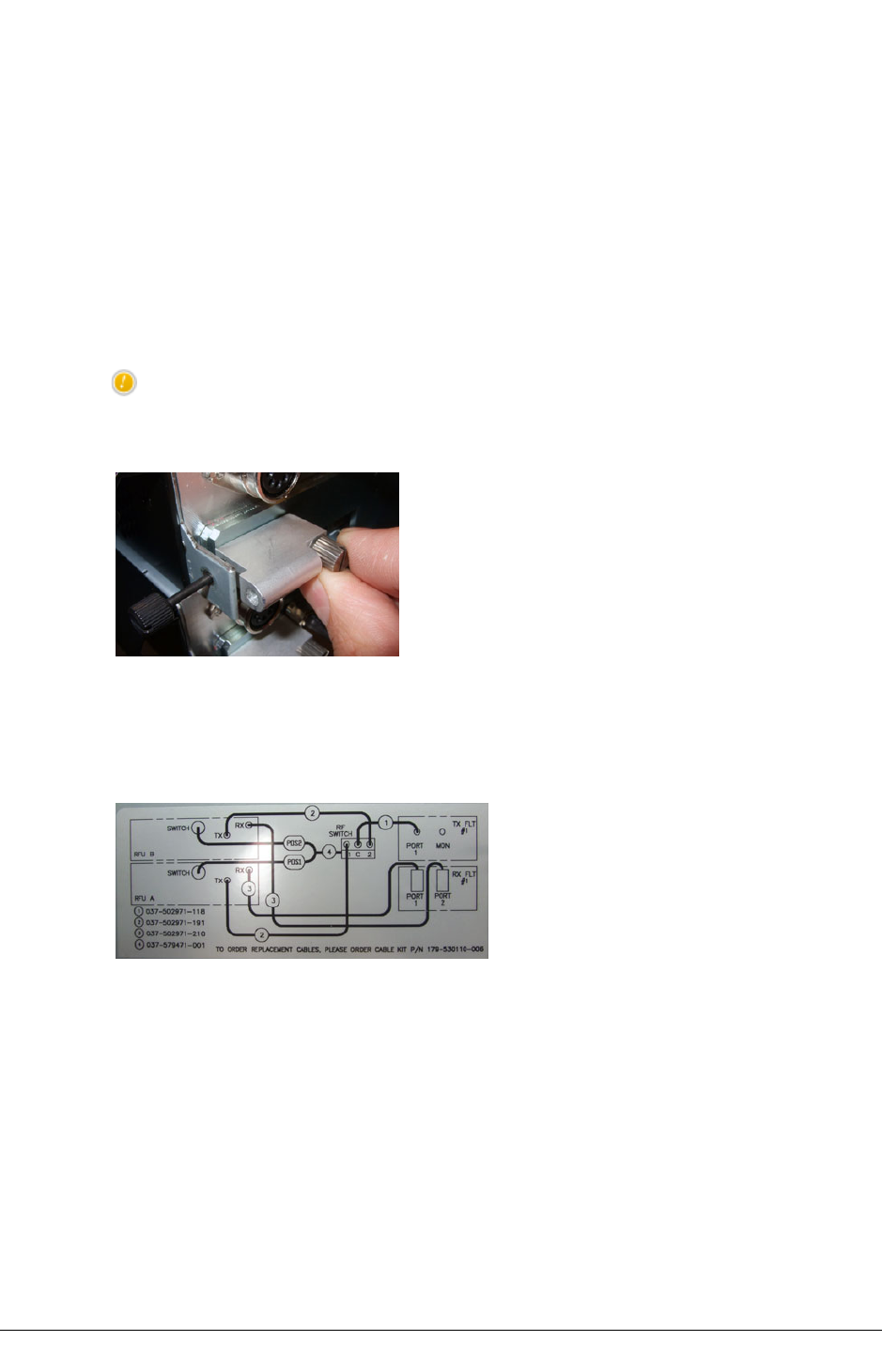
IRU 600 INSTALLATION CHAPTER 5
install an INU/INUE/IDU GE3 16x.
oFor IRU 600v3/v4 no chassis spacing is required, but a 1RU space should be
retained above the top and below the bottom of the chassis stack to ease hand
access to RFU - ACU cable installation.
3. Locate and secure RFU(s) and ACU in the IRU 600 chassis.
oFor IRU 600v3/v4 the chassis-mounted post fitted to secure the right side of
the RFU / left side of the ACU front cover is removable.
oThis is to assist connection/dis-connection of the RFU SMA connectors, and
the DIN5 connector on 1+1 configurations.
CAUTION: When re-fitting the IRU 600v3/v4 removable post do not over-tighten. Thumb-
tighten only to avoid thread-striping.
Figure 35. IRU 600v3 Removable Post
4. Connect the RFU(s) to the ACU using the supplied RF cables. Refer to the cabling
diagram on the rear side of the ACU front panel. The lower RFU is A-side, the top B-side.
A-side is the default online RFU in a 1+1 protected pairing.
Figure 36. Example Cabling Diagram on Rear of ACU Front Panel
lFor IRU 600v2 and IRU 600v3/v4 ACUs fitted with a Tx coaxial switch, fit the
RFU-to-switch cable assembly.
oFor IRU 600v3/v4 the fixing post in front of the RFU connectors can be removed
to aid connector access. See step 3 above.
oEnsure cables connect to the correct RFU. Refer to the cabling diagram on the
rear side of the ACU front cover.
oEnsure DIN5 RFU cable connectors are correctly inserted and locked using
the connector locking ring - turn the ring clockwise until clicked into its locked
position.
oEnsure the switch connector is held secure using its screw fasteners.
AVIAT NETWORKS JULY 2018 91
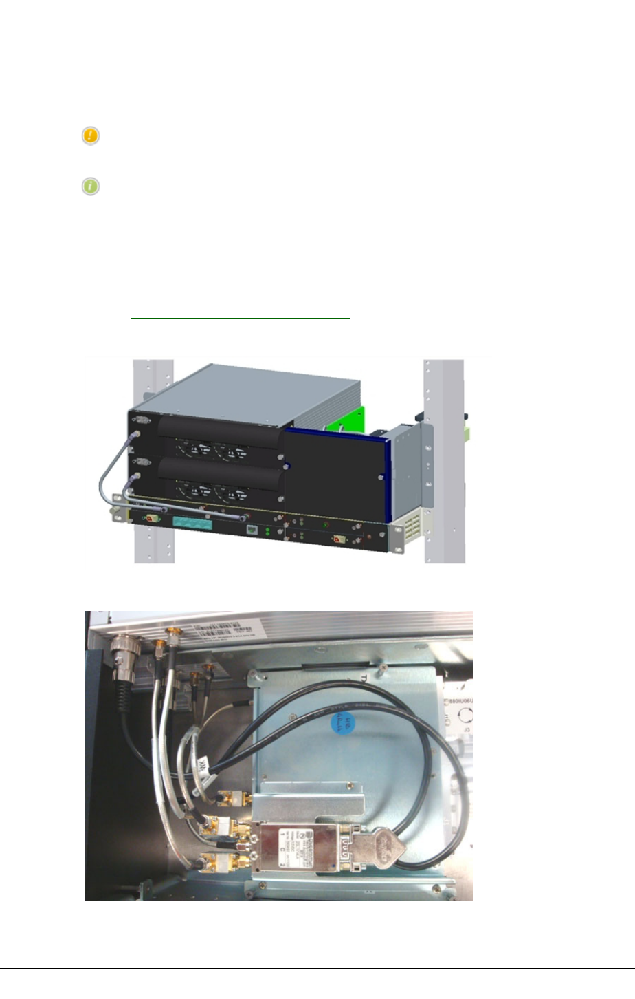
CHAPTER 5IRU 600 INSTALLATION
oThe Tx switch cable must remain securely connected at all times. Incorrect
communication between the RFU and Tx switch may result in mismatched A-
side and B-side operation and loss of standby.
CAUTION: Check installation of DIN5 RFU cable connectors. The lock ring should home
with an audible click.
NOTE: Multiple voltage pules are used to energize the Tx switch relay.
lConnect the RFU(s) to the INU/INUe RAC 70, RAC 60/60E or RAC 6X/6XE card(s)
using the supplied IF cable(s). The minimum bend radius of the IF cable is 25
mm.
lFor the IRU 600v2 HP RFU and for the IRU 600v3/v4 EHP RFU, which are
additionally powered using a separate DC input on their front panel, refer to
Power Supply Connection on page 95 for DC power installation.
Figure 37. IRU 600 and INU
Figure 38. IRU 600v2 Tx Switch and RFUv2 Connections
92 JULY 2018 AVIAT NETWORKS

IRU 600 INSTALLATION CHAPTER 5
Figure 39. IRU 600v3/v4 Tx Switch and RFUv3 Connections
CAUTION: Ambient temperatures must not exceed 550C (1310F). If installed in a rack cabinet, it is
the ambient within the cabinet.
Chassis Grounding
The chassis grounding stud accommodates ground cables up to 16 mm2(AWG 6).
The stud also provides jack plug connection for a wrist strap.
lGround the IRU 600 from the grounding stud to the rack/frame ground bar using
4 mm2(AWG 12) green PVC insulated stranded copper wire with a suitably sized
crimp lug at the ground bar end (supplied by the installer). For NEBS grounding
compliance, see below.
lIf the equipment rack/frame requires grounding, use 16 mm2(AWG 6) wire
from its ground bar to the station ground.
NEBS Compliant Grounding
These grounding requirements apply for a NEBS compliant installation.
lGround the IRU 600 from the grounding stud to the rack/frame ground bar using
16 mm2 (AWG 6) green PVC insulated stranded copper ground wire (not 4 mm2)
together with a star washer under the grounding screw at the ground-bar end.
Torque the grounding post screw to 1.2-1.5 Nm (10-13 in-lbs).
lCoat all bare conductors with an appropriate antioxidant compound before
crimp connectors are fitted.
lEnsure all unplated connectors, braided strap, and bus bars are brought to a
bright finish and then coated with an antioxidant before they are connected. This
does not apply to tinned, solder-plated, or silver-plated connectors and other
plated connection surfaces – but all must be clean and free of contaminants.
AVIAT NETWORKS JULY 2018 93

CHAPTER 5IRU 600 INSTALLATION
lWhere metallic raceway fittings are installed ensure all fittings are tightened to
provide a permanent low-impedance path.
Safety Requirements for Equipment Grounding
lDo not assume that an existing rack or mounting frame is correctly grounded.
Always check the integrity of the ground connections, which must include a check
through to the master ground for the station, which should be located at the point
of cable entry to the equipment building. Ground wires must provide a direct, low
impedance path to the master ground bar.
lDo not connect other equipment to the same grounding cable as the INU. Each
item of equipment in a rack must be separately grounded to the rack ground bar.
lThe INU / IRU 600 must be located in the same immediate area (adjacent
racks/cabinets) as all other equipment with a (ground) connection to a common
DC supply source.
lAll intra-building signal cabling must be shielded, and both ends of each shield
must be grounded.
lThere must be no switching or disconnecting devices in the grounded circuit
conductor between the DC source and the point of connection of the grounding
electrode conductor.
Waveguide Installation
For instructions on waveguide installation and associated pressurization and grounding
requirements, refer to the relevant documentation from the waveguide supplier. General
guidance can be found in Aviat Networks Best Practices Guide.
Waveguide Connection to ACU
Connect ACU antenna port(s) to waveguide(s) using flexible waveguide.
lInformation on required waveguide flanges and recommended waveguide types
are listed in the following table.
lRemove and discard any protective flange/port covers before installation.
94 JULY 2018 AVIAT NETWORKS
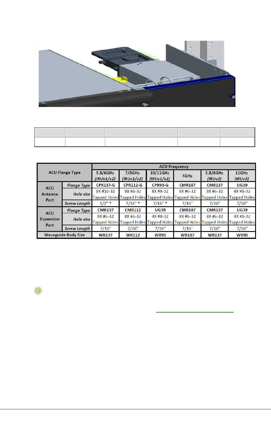
IRU 600 INSTALLATION CHAPTER 5
Figure 40. ACU and Waveguide Connection
Table 7. ACU Flange Data
Freq, GHz Flange Type Holes Screw Length Waveguide
5.8/6 CPR 137 G 8 x #10-32 tapped holes 1/2" WR 137
* The screw length assumes a flex twist mating flange thickness of 1/4”.
Power Supply Connection
NOTE: The DC power supply must be SELV compliant (maximum limited
60 Vdc).
For IRU 600 power consumption figures refer to INU Power Supply on page 103.
Power Supply Requirements
RFUs not fitted with a front-panel D-Sub M/F 2W2 power connector are powered via the IF
cable from their associated INU/INUe. These are:
lStandard power IRU 600(v1) and IRU 600v2 RFUs
lStandard/High power IRU 600v3/v4 RFUs
RFUs fitted with a front-panel D-Sub M/F 2W2 power connector are additionally powered by
a front panel connector. These are:
AVIAT NETWORKS JULY 2018 95

CHAPTER 5IRU 600 INSTALLATION
lHigh power IRU 600(v1) and IRU 600v2 RFUs
lExtra high-power (EHP) IRU 600v3/v4 RFUs
lThe power connector and cable are identical to that used for the INU/INUe.
-48 Vdc and +24 Vdc Operation
The associated INU/INUe requires a -48Vdc power input. For operation from a +24 Vdc
power supply a +24 to -48 Vdc converter is required.
lThe plug-in PCC (Power Converter Card) can be installed to convert +24 Vdc to -48
Vdc for connection to the -48 Vdc connector on the NCC. Two PCCs are required if
an NPC is also installed.
oA PCC supports power consumption for the INU/INUe plus a maximum of
three V1 or V2 RFUs, or a maximum of two V3/V4 RFUs. See PCC +24 Vdc
Operation on page 1
lOtherwise a suitable external converter can be used - contact Aviat Networks for
details.
RFUs fitted with the front-panel D-Sub M/F 2W2 power connector support a wide-mouth +/-
21 to 60 Vdc connection.
lBoth +ve and -ve pins are isolated from ground. They can be powered from +24
Vdc or -48 Vdc supplies.
lThe integral DC/DC converter provides polarity protection, under/over voltage
shutdown, over-current limit, and thermal shutdown. There are no serviceable
fuses.
lRun the supplied power cable through to a dedicated circuit breaker on the rack
power connect panel.
oFor a -48 Vdc supply, connect the blue wire to -48 Vdc (live), and the black wire
to ground/+ve. The circuit breaker should have rating of 3 A.
oFor a +24 Vdc supply, connect the blue wire to +24 Vdc (live), and the black
wire to ground/-ve. The circuit breaker should have rating of 5 A.
oFor NEBS compliance the battery return connection is to be treated as an
isolated DC return (DC-I), as defined in GR-1089-CORE.
CAUTION: Use the RFU circuit breaker as the power connect/disconnect device - do not
use the front-panel 2W2 DC connector for live power connect/disconnect.
IRU 600(v1) and IRU 600v2
Standard power RFUs are powered over the IF cable from its INU/INUe.
High power RFUs (HP) are additionally powered using a separate DC input on their front
panel.
IRU 600v3
lThe Std/HP RFU is powered over the IF cable from its INU/INUe.
oThe RFU is SW configured for standard or high-power. High power operation
96 JULY 2018 AVIAT NETWORKS

IRU 600 INSTALLATION CHAPTER 5
requires installation of a feature license (EZF-61 to 66, or EZG-61 to 66).
lA feature license is not required for the EHP RFU.
Insertion Loss Labels
Labels on the ACU provide factory-measured insertion loss data. These list the loss for
each filter and circulator, and the total loss through the ACU (filters, circulators, cables,
plus any protection components, such as Tx switch and couplers). Total (combined) loss
figures are entered into Portal to enable computation of Tx power and RSL figures at the
ACU antenna waveguide port(s) based on the RFU measured values of Tx power and RSL.
For IRU 600v2 and IRU 600v3/v4 an additional label shows the insertion loss of the Tx
monitoring port. The value must be considered when measuring output power with a power
meter.
Expansion Port Use
The expansion port allows system expansion through the addition of co-located IRU 600
radios, or external radio equipment.
When multiple carriers are deployed on a common branching network (same antenna), the
selection and installation of branching network components must be such that threshold
degradation caused by intermodulation products is avoided.
lWhile the IRU 600 ACUs are specified to avoid placing undue constraints on
frequency planning for multiple carrier systems, the following conditional
requirements are intended to provide guidelines on the selection and installation
of branching frequencies and components.
oThe intermodulation frequency products that result from combining two or
more transmitter frequencies on a common antenna feeder should be 48 MHz
or more above or below each of the receiver frequencies present on the same
antenna feeder.
oSystems employing carrier frequencies with potential to cause
intermodulation products within 48 MHz of any of the receiver frequencies
present on the same antenna branching network (feeder) must be designed
and installed to mitigate the effects of such intermodulation products.
FAN Module
The fan units in an RFU are removable for service/replacement. Fan module replacement
is non-traffic affecting.
CAUTION: Fan module hazard - keep away from moving fan blades.
AVIAT NETWORKS JULY 2018 97
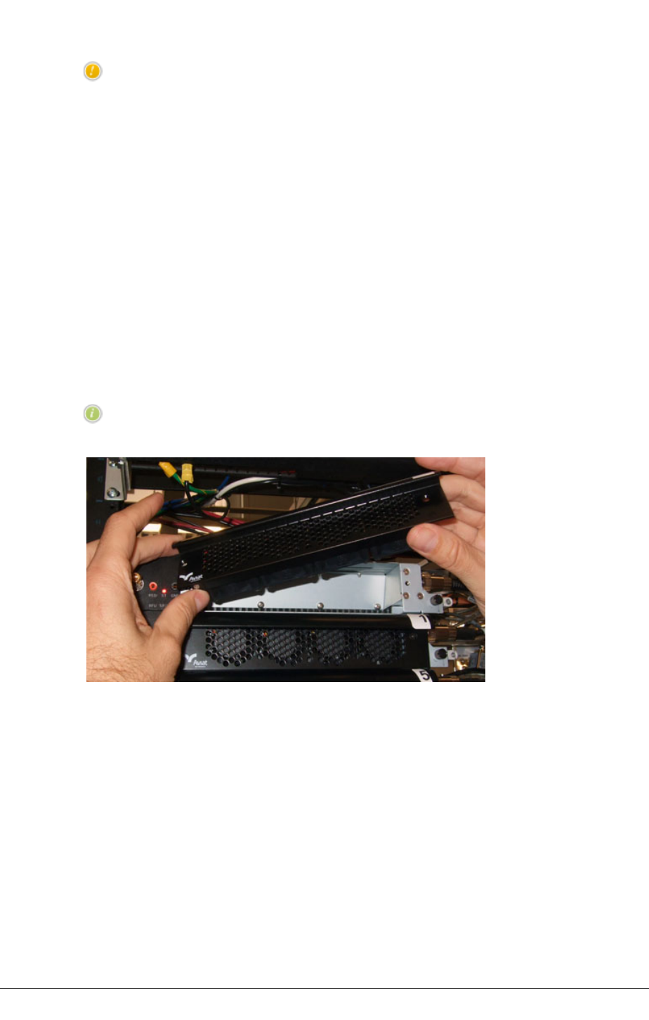
CHAPTER 5IRU 600 INSTALLATION
CAUTION: Handle the FAN module with care. Do not physically shock the module or touch
the fan impeller blades. Doing so can move the impeller off-center and cause premature
fan failure.
lFor IRU 600(v1) and IRU 600v2 a fan cover is removed to expose the two fans.
Removal and replacement is per-fan.
lFor the IRU 600v3 the four fans are located on a removable/replaceable front-
cover fan tray.
oTo remove, unscrew the fan tray fasteners, ease outwards, and carefully dis-
connect the rear cable connector. Fan replacement is per-tray.
oWhen replacing the fan tray ensure the supply cable is routed so it is not pinched
when the tray is fastened, and that during operation it cannot come into contact
with a fan.
lFan operation is monitored. Each fan has a matching alarm.
lFor IRU 600(v1) and IRU 600v2 both fans are operated at a fixed speed.
lIRU 600v3 fan speed is temperature-dependent.
NOTE: If one fan needs to be replaced, replace all fans.
Figure 41. IRU 600v3 Fan Tray Removal
Chassis Adapter Kit for IRU 600v3 and IRU 600v4
RFUs
An adaptor kit (part No. 179-530112-002) is available to enable installation of an IRU 600v3
RFU into an IRU 600v2 or IRU 600v1 chassis.
Aadaptor kits to enable installation into an IRU 600v2 or IRU 600v1 chassis are as follows:
l(Part No. 179-530112-002) is available to enable installation for an IRU 600v3
RFU, and
l(Part No. 179-530508-001) for an IRU 600v4 RFU.
98 JULY 2018 AVIAT NETWORKS

IRU 600 INSTALLATION CHAPTER 5
The kit is used where an existing V2 or V1 chassis is to be upgraded to V3/V4 capabilities –
the existing V2 or V1 RFU is replaced by a V3/V4 Std/HP RFU, or EHP RFU.
One kit is required per IRU 600v3/v4 RFU.
NOTE: For the IRU 600v3 or v4 to be recognized the installed Eclipse SW
must be 07.03.56, or later compatible release.
The kit, comprises:
lA riser plate that properly locates the physically smaller IRU 600v3/v4 RFU
within the V2 or V1 chassis.
lExtension plate for the V3 or V4 Fan Tray to provide a neat and integrated
appearance in its V2 or V1 host chassis. The extension plate is designed for use
with all V3 or V4 Fan Tray types.
lVarious screws and an overlay to mask an unused screw hole.
lInstallation instructions.
NOTE:
lWhere the V3 or V4 Std/HP RFU is installed an HP feature license (EZF-61 to 66,
or EZG-61 to 66) must be installed to enable the HP option.
lWhere the V3 or V4 EHP RFU is installed a feature license is not required – the
EHP capability is inclusive.
lWhere a V3 or V4 RFU (or V2) RFU is used in a system with a V1 ACU, the 'Mute
Offline Tx Power' tab on the IRU 600v3/v4 (or IRU 600v2) plug-ins RAC/RFU
screen may be retained until Break/Create protection is toggled. In the Protection
screen, break protection and click Send, followed by create protection and Send,
after which the 'Mute Offline Tx Power' tab will be removed to reflect that it is
operating in a V1 environment.
For information on V4, V3, V2, V1 compatibility see IRU 600 Compatibility on page 72.
Procedure
lInstall the adapter kit on the V3 or V4 RFU according to the adapter kit
instruction sheet.
lIf the V3 or V4 RFU is Std/HP and the HP capability is required, install the
relevant HP feature license. (A feature license is not required for the EHP RFU).
lInstall the V3 or V4 RFU in the IRU 600 V1 or V2 chassis according to the
instruction sheet.
lFor the V3 or V4 EHP RFU install the supplied DC power cable. Ensure it is
terminated onto a correctly sized circuit breaker. See Power Supply Connection
on page 95.
lConfigure the IRU 600 with V3 or V4 RFU according to the instructions provided
in the Portal Chapter of this manual. See Configuration Procedures for RAC
70/7X, RAC 60/6X and RAC 60E/6XE on page 1.
AVIAT NETWORKS JULY 2018 99


INSTALLING THE INU AND INUE CHAPTER 6
Chapter 6. Installing the INU and INUe
The INU and the INUe are the indoor units for the Eclipse Node.
This chapter includes:
lINU/INUe Description on page 102
lCompact Flash Card on page 1
lINU/INUe Installation Requirements on page 115
lInstallation on page 118
lPlug-in Slot Configuration
lPlug-in Installation Requirements on page 121
For a description of the plug-ins, refer to the Eclipse Platform Product Description.
For information on user-interface connector and cable data, refer to INU/INUe and IDU
Connector and Cable Data on page 1.
CAUTION: With the increase in the capabilities and complexity of some new plug-in
modules, such as RAC 60E, RAC 6XE, DAC GE3, Compact Flash cards with increased
capacity are required. See Compact Flash Card on page 1.
CAUTION: Do not turn power off within 10 minutes of initial INU/INUe turn-on, or initial
turn-on after a new compact flash card is installed.
CAUTION: There must be a minimum of 50 mm (2”) of side spacing from the INU/INUe to
any rack panels, cable bundles or similar, and 50 mm (2”) of space to the front and back
of the RF section to ensure proper ventilation.
AVIAT NETWORKS JULY 2018 101
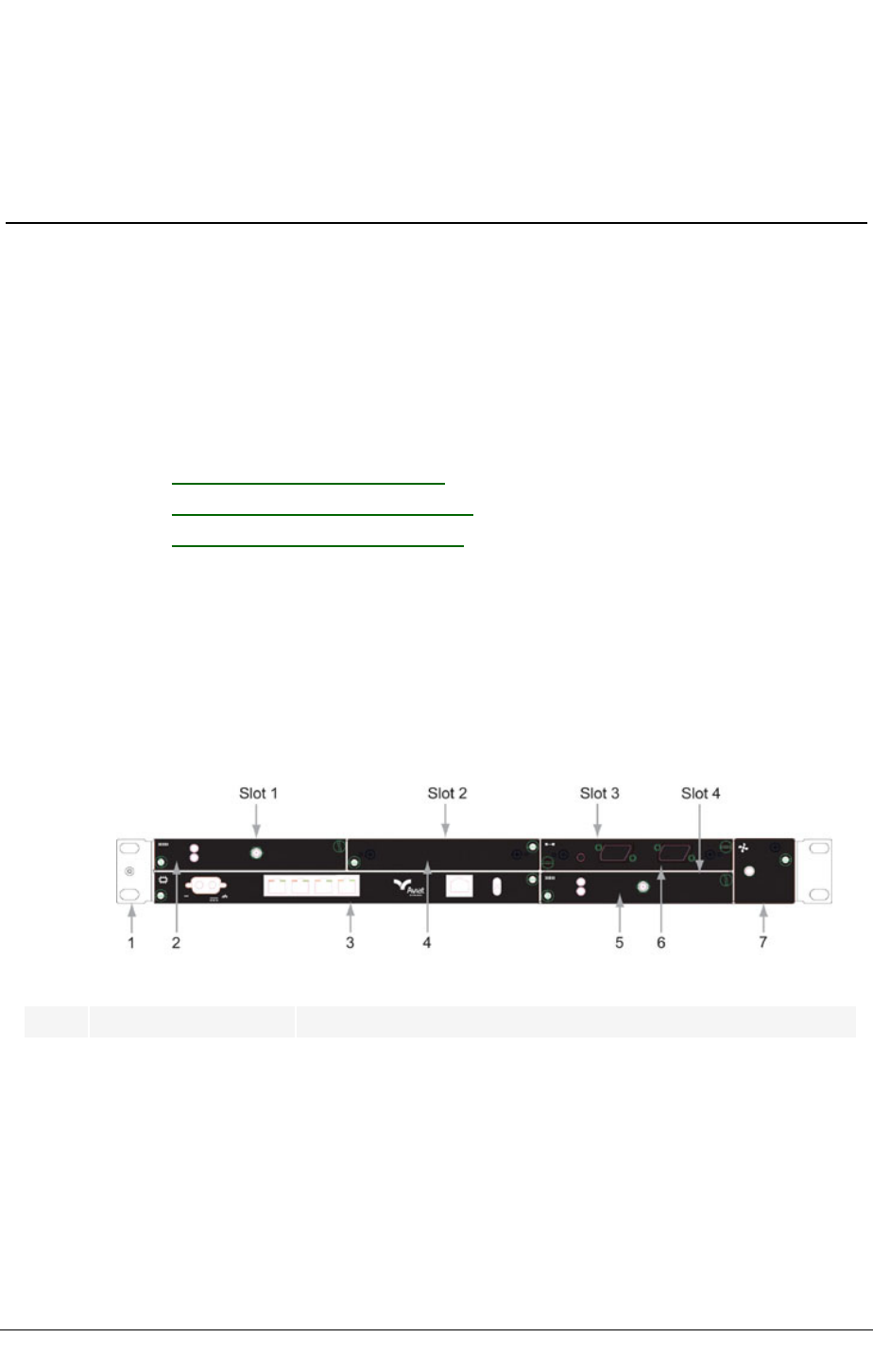
CHAPTER 6INSTALLING THE INU AND INUE
INU/INUe Description
The INU/INUe is a rack-mounted unit that pairs with one or more ODUs or one or more IRU
600s to make an Eclipse Node.
An INU/INUe comprises a chassis (IDC/IDCe) and plug-ins.
The IDC/IDCe has dedicated slots for the NCC and FAN plug-ins, and either four slots (IDC)
or ten slots (IDCe) available for optional RAC, DAC, AUX and NPC plug-ins.
Refer to:
lIDC V1 and IDC V2 and INU Front PanelLayout in this section
lFAN Air Filter Option on page 113
lPower Line Filter Option on page 114
lPlug-in Slot Configuration on page 1
INU Front Panel Layout
This figure is an example of an INU front panel, with one DAC x16, two RAC30s, and a
blanking panel over the unused slot. For a full description of all plug-ins and their front
panel layouts, refer to the Eclipse System Description.
Figure 42. Typical INU Front Panel Layout
No Item/Label Description
1Rack Ear and
grounding stud
Rack attachment bracket for the IDC. One ear has a combined ESD and
IDC grounding stud. The ears can be fitted either side, which provide
flush-with-rack-front mounting.
2RAC 30 RAC 30 fitted in slot 1
3NCC Mandatory Node Control Card (dedicated slot)
4Blank Panel Blanking panel fitted to slot 2
5RAC 30 RAC 30 fitted in slot 4
102 JULY 2018 AVIAT NETWORKS

INSTALLING THE INU AND INUE CHAPTER 6
No Item/Label Description
6DAC 16x 16xE1/DS1 DAC fitted in slot 3
7FAN Mandatory fan plug-in (dedicated slot)
INU Power Supply
INUs require a -48Vdc power supply (+ve earth) but will operate to specification over a
voltage range of -40.5 to -60Vdc.
The return (+ve) pin on the NCC and NPC power supply connectors is clamped to chassis
ground via polarity-protecting power FETs.
lNCC and NPC power inputs are reverse polarity protected (the input fuse will not
blow if polarity is reversed).
For NEBS compliance the battery return connection is to be treated as a common DC return
(DC-C), as defined in GR-1089-CORE.
Where operation from a +24 Vdc PSU is required, the plug-in PCC option provides voltage
conversion from + 24 (19 to 36) Vdc to -56 Vdc for connection to the NCC -48Vdc input. -56
Vdc represents a typical (maximum) float voltage for a battery-backed -48 Vdc supply.
Otherwise an external +24 to -48 Vdc converter can be used - contact Aviat Networks for
details.
The dc power supply must be UL or IEC compliant for SELV (Safety Extra Low Voltage)
output (60Vdc maximum limited).
Voltage changes due to the regulation of the power supply must not exceed a change-rate
(linear variation slope) of 7 V/ms, as specified in TSI EN 300 132-2 V2.4.6. Applies over
variations between -40.5 Vdc to -57 Vdc.
Power Consumption and INU Load Maximums
Total power consumed is dependent on the number and type of plug-in cards, the number
and type of ODU(s) or IRU 600, plus for the ODUs, the frequency band.
INU loading maximums, the number and type of RACs and DACs that can be installed in an
INU, are determined by the load capacity and temperature limits of the DC converter in the
NCC and NPC, which supply various DC rails to the plug-in cards. Load maximums are also
dependent on the SW release in use, and the version of NCC and NPC installed. For more
information see Node Card Maximums below.
lODUs, IRU 600s and FANs are not powered via the NCC converter, meaning the
ODU and IRU 600 type does not impact INU link loading. Their DC supply is taken
from the -48 Vdc power supply input connector.
lHowever, if a PCC is installed for +24 Vdc operation, the INU cards and associated
ODUs or IRU 600s are supplied from the PCC, meaning PCC power limits are
AVIAT NETWORKS JULY 2018 103

CHAPTER 6INSTALLING THE INU AND INUE
determined by the INU cards and by the number and type of ODUs or IRU 600s
fitted.
lA PCC should always be installed to receive maximum FAN cooling. This means it
should be installed in the immediate FAN-side slots in an INU/INUe.
NOTE: A suitable external +24 Vdc to -48 Vdc converter can be used
instead of the PCC. Contact Aviat Networks for details.
Power Consumption
Power consumption figures are for a -48 Vdc supply voltage at normal room ambients.
Plug-in Cards
The table below lists nominal power consumption figures for Eclipse plug-ins.
lUse these together with the ODU or IRU600 consumption figures in the following
tables to determine total nodal power consumption.
lWhen operated with an ODU, cable power dissipation should be considered.
Table 8. Typical Plug-in Power Consumptions
Item Consumption W
RAC30v3, RAC 30A 8
RAC40 10
RAC 4X 15
RAC 3x 11
RAC 60/60E 12
RAC 6X/6XE 17
RAC 70 13
DAC ES, 16x, 16xV2, 4x, 3xE3/DS3, 3xE3/DS3M 2.5
DAC GE, 155o, 2x155o, 2x155e, 155oM, 155eM 4
DAC GE3 13
NCM 10
NCC 11
NPC 8
AUX 1
FAN 1RU* 2
FAN 2RU* 2
* FANs are not powered via the NCC/NPC converter.
104 JULY 2018 AVIAT NETWORKS

INSTALLING THE INU AND INUE CHAPTER 6
IRU 600(v1) and IRU 600v2
The table below lists nominal figures.
lFor a standard power RFU, DC power is provided from its INU/INUe via its RAC -
RFU cable (in the same way as an ODU).
lFor a high-power RFU, power is supplied via its RAC cable and additionally by a
front-mounted DC connector to an external DC power source. High power is
enabled through feature licensing. See Licensing on page 1.
Table 9. Typical IRU 600(v1) and IRU 600v2 Power Consumption
Configuration Band Power
Sourced
from INU
Power Sourced
from External
DC Connector
Total DC
Power
1+0 Configurations Std Power – Normal Operation L6/U6 52W N/A 52W
1+0 Configurations Std Power –All Tx Muted L6/U6 30W N/A 30W
1+0 Configurations High-Power – Normal Operation 5.8/L6/U6
/7/8/10/1
1
52W 38W 90W
4GHz N/A 80W 80W
1+0 Configurations High-Power – All Tx Muted 5.8/L6/U6
/7/8/10/1
1
30W 4W 34W
4GHz N/A 25W 25W
1+1 Configurations Std Power – Normal Operation L6/U6 82W N/A 82W
1+1 Configurations Std Power – All Tx Muted L6/U6 60W N/A 60W
1+1 Configurations High-Power – Normal Operation 5.8/L6/U6
/7/8/10/1
1
82W 42W 124W
4GHz N/A 105W 105W
1+1 Configurations High-Power – All Tx Muted 5.8/L6/U6
/7/8/10/1
1
60W 8W 68W
4GHz N/A 50W 50W
1+1 Configurations employing FD Std Power – Normal
Operation
L6/U6 104W N/A 104W
1+1 Configurations employing FD Std Power – All Tx
Muted
L6/U6 60W N/A 60W
1+1 Configurations employing FD High-Power –
Normal Operation
5.8/L6/U6
/7/8/10/1
1
104W 76W 180W
4GHz N/A 160W 160W
AVIAT NETWORKS JULY 2018 105

CHAPTER 6INSTALLING THE INU AND INUE
Configuration Band Power
Sourced
from INU
Power Sourced
from External
DC Connector
Total DC
Power
566651+1 Configurations employing FD High-Power –
All Tx Muted
5.8/L6/U6
/7/8/10/1
1
60W 8W 68W
4GHz N/A 50W 50W
1+1 Configurations Std Power – MHSB (IRU 600v2
Only)
L6/U6 104W N/A 104W
1+1 Configurations High-Power – MHSB (IRU600v2
Only)
5.8/L6/U6
/7/8/10/1
1
104W 76W 180W
4GHz N/A 160W 160W
1+1 Configurations Std Power – MHSB (IRU 600v2
Only)
L6/U6 82W (avg)
104W
(peak)
N/A 82W
(avg)
104W
(peak)
1+1 Configurations High-Power – MHSB (IRU600v2
Only)
5.8/L6/U6
/7/8/10/1
1
82W (avg)
104W
(peak)
42W (avg)
76W (peak)
124W
(avg)
180W
(peak)
4GHz N/A 105W (avg)
160W (peak)
105W
(avg)
160W
(peak)
IRU 600v3
The table below lists typical and maximum power consumption figures at maximum Tx
power settings.
lA common RFU is used for standard (SP) and high-power (HP) modes. High
power is enabled through feature license. See Licensing on page 1.
oFor both standard power and high-power operation DC power to the RFU(s) is
provided from its INU/INUe via the RAC - RFU cable.
lThe EHP RFU power is supplied via its INU/INUe RAC cable and additionally by a
front-mounted DC connector to an external DC power source.
Table 10. Typical and Maximum IRU 600v3 Power Consumption
Configuration Typical
INU/INUe
Source
Pwr
Max
INU/INU
eSource
Pwr
Typical
External
DC
Source
Pwr
Max
External
DC Source
Pwr
1+0 Configurations IRU 600SPv3 – Normal Operation 58W 63W N/A N/A
1+0 Configurations IRU 600SPv3 – All TX Muted 42.5W 46.5W N/A N/A
106 JULY 2018 AVIAT NETWORKS

INSTALLING THE INU AND INUE CHAPTER 6
1+0 Configurations IRU 600HPv3 – Normal Operation 63W 68W N/A N/A
1+0 Configurations IRU 600HPv3 – All TX Muted 42.5W 46.5W N/A N/A
1+0 Configurations IRU 600EHPv3 L6 – Normal
Operation
58W 63W 56W 60W
1+0 Configurations IRU 600EHPv3 U6 – Normal
Operation
61.5W 65.5W 60W 63.5W
1+0 Configurations IRU 600EHPv3 11GHz – Normal
Operation
58W 63W 43W 46W
1+0 Configurations IRU 600EHPv3 L6/U6/11– All TX
Muted
42.5W 46.5W 3.5W 4W
1+1 Configurations IRU 600SPv3 – HSB Mode 100.5W 109.5W N/A N/A
1+1 Configurations IRU 600SPv3 – All TX Muted 85W 93W N/A N/A
1+1 Configurations IRU 600HPv3 – HSB Mode 105.5W 114.5W N/A N/A
1+1 Configurations IRU 600HPv3 – All TX Muted 85W 93W N/A N/A
1+1 Configurations IRU 600EHPv3 – L6 - HSB Mode 100.5W 109.5W 59.5W 64W
1+1 Configurations IRU 600EHPv3 – U6 - HSB Mode 104W 112W 63.5W 67.5W
1+1 Configurations IRU 600EHPv3 – 11 - HSB Mode 104W 112W 43W 46W
1+1 Configurations IRU 600EHPv3 – L6 - All TX Muted 85W 93W 7W 8W
1+1 Configurations IRU 600EHPv3 – U6 - All TX
Muted
85W 93W 7W 8W
1+1 Configurations IRU 600EHPv3 – 11 - All TX
Muted
85W 93W 7W 8W
1+1 FD Configurations IRU 600SPv3 – Normal
Operation
116W 126W N/A N/A
1+1 FD Configurations IRU 600SPv3 – All TX Muted 85W 93W N/A N/A
1+1 FD Configurations IRU 600HPv3 – Normal
Operation
126W 136W N/A N/A
1+1 FD Configurations IRU 600HPv3 – All TX Muted 85W 93W N/A N/A
1+1 FD Configurations IRU 600EHPv3 – L6 - Normal
Operation
116W 126W 112W 120W
1+1 FD Configurations IRU 600EHPv3 – U6 - Normal
Operation
123W 131W 120W 127W
1+1 FD Configurations IRU 600EHPv3 – 11GHz -
Normal Operation
116W 126W 86W 92W
1+1 FD Configurations IRU 600EHPv3 L6/U6/11– All
TX Muted
85W 93W 7W 8W
1+1 Configurations IRU 600SPv3 – MHSB Mode 116W 126W N/A N/A
1+1 Configurations IRU 600HPv3 – MHSB Mode 126W 136W N/A N/A
1+1 Configurations IRU 600EHPv3 – L6-MHSB Mode 116W 126W 112W 120W
1+1 Configurations IRU 600EHPv3 – U6-MHSB Mode 123W 131W 120W 127W
1+1 Configurations IRU 600EHPv3 – 11-MHSB Mode 116W 126W 86W 92W
1+1 Configurations IRU 600SPv3 – P-MHSB Mode 100.5W
Avg
116W Peak
109.5W
Avg
126W Peak
N/A N/A
AVIAT NETWORKS JULY 2018 107

CHAPTER 6INSTALLING THE INU AND INUE
1+1 Configurations IRU 600HPv3 – P-MHSB Mode 105.5W
Avg
126W Peak
114.5W
Avg
136W Peak
N/A N/A
1+1 Configurations IRU 600EHPv3 –L6 - P-MHSB
Mode
100.5W
Avg
116W Peak
109.5W
Avg
126W Peak
59.5W Avg
112W Peak
64W Avg
120W Peak
1+1 Configurations IRU 600EHPv3 –U6 - P-MHSB
Mode
104W Avg
123W Peak
112W Avg
131W Peak
63.5W Avg
120W Peak
67.5W Avg
127W Peak
1+1 Configurations IRU 600EHPv3 –11 - P-MHSB
Mode
100.5W
Avg
116W Peak
109.5W
Avg
126W Peak
46.5W Avg
86W Peak
50W Avg
92W Peak
IRU 600v4
The table below lists maximum power consumption figures at maximum Tx power settings.
lA common RFU is used for standard (SP) and high-power (HP) modes. High
power is enabled through feature license.
lFor both SP and HP operation, DC power to the RFU(s) is provided from its
INU/INUe via the RAC - RFU cable.
lThe EHP RFU power is supplied via its INU/INUe RAC cable and additionally by a
front-mounted DC connector to an external DC power source.
Table 11. Maximum Power Consumption (W) - IRU 600v4 with RAC 70
Maximum Output Power (dBm)
SP/HP Configuration,
1+0 unit (Typical)
31.5 27.0 22.0 Tx Muted
11 GHz 64.3 47.5 39.8 23
NOTE:
lFor an EHP Configuration, 1+0 unit, the Maximum Power Consumption
is 100 W.
lTX power values at RFM port, under ambient temperature of +30 °C.
lTX power level shown is referenced at the 1+0 ACU antenna port.
lThe power consumption is channel bandwidth independent and is the
same for any given TX power.
lThe delta between TX output power at 1+0 ACU antenna port and the
RFM port is the 1+0 ACU loss. For 11 GHz, ACU loss is 2.0 dB.
Node Card Maximums
From SW release 5.04 improvements in the cooling fan operating logic allow higher card
loadings coupled with maximum ambients to 55oC (131oF), or 45oC (113oF).
lFrom software release 5.04 fan logic improvements allow higher INUe loading
when an NPC is installed.
lAn NPC must be fitted in an INUe where specified below. The NPC provides power
108 JULY 2018 AVIAT NETWORKS

INSTALLING THE INU AND INUE CHAPTER 6
supply load sharing with the NCC, allowing the overall loading to be increased.
Should the NPC fail, airflow from the 2RU FAN is increased to compensate.
lExtended FAN failure/impairment detection is included. For example, an alarm
will be raised on a reduction in fan speed (RPM), such as can occur as a result of
bearing wear/friction.
lThe loading maximums are designed to ensure systems will continue to operate
correctly in the event of failure of either the NCC or NPC.
From November 2012 new card maximums (loading rules) apply with the availability of
updated high-output NCC and NPC cards. These new cards have part numbers of EXN-003
and EXS-002 respectively.
lThe updated NCC and NPC cards are required where node loading exceeds 120W.
lThe prior NCC and NPC cards, those with part numbers EXN-002 and EXS-001
respectively, must only be retained where node loadings do not exceed 120W.
CAUTION: When planning the number and type of cards to be installed in an INUe or INU,
the following rules must be observed. These rules apply retrospectively (back to
software release 5.04).
CAUTION: The loading rules below must be observed by the installer - there is no built-in
mechanism to report or limit an incorrect dimensioning of power supply consumption.
INUe Loading Rules for Operation up to 55ºC (131ºF)
The following loading rules must be followed when dimensioning the total power
consumption of an INUe that is required to operate in ambient temperatures up to 55ºC
(131ºF):
lIf the total power consumption of all cards installed exceeds 85W, an NPC must
be fitted, a 2RU FAN card must be fitted, and 5.04 or later SW loaded.
lWith this configuration confirmed (NPC + 2RU FAN + 5.04 SW or later) the
maximum INUe loading enabled is:
o120W with NCC EXN-002 and NPC EXS-001.
o125W with high-output NCC EXN-003 and NPC EXS-002.
oThe installed total of DAC GE3 cards must not exceed four.
lIf an earlier version of SW is loaded, the maximum INUe loading allowed is 85
Watts. This applies whether or not an NPC and 2RU FAN are fitted.
CAUTION: 55ºC (131ºF) operation does not apply to the PCC. Operational ambient
temperatures with a PCC installed must not exceed 450C (1130F).
Install a suitable external +24 Vdc to -48 Vdc converter to avoid the PCC
operational ambient temperature limits. Contact Aviat Networks for details.
AVIAT NETWORKS JULY 2018 109

CHAPTER 6INSTALLING THE INU AND INUE
INUe Loading Rules for Operation up to 45ºC (113ºF)
The following loading rules must be followed when dimensioning the total power
consumption of an INUe that is operating in ambient temperatures that do not exceed 45ºC
(113ºF):
lIf the total power consumption of all cards installed exceeds 85W, an NPC must
be fitted, a 2RU FAN card must be fitted, and 5.04 or later SW loaded.
lWith this configuration confirmed (NPC + 2RU FAN + 5.04 SW or later) the
maximum INUe loading enabled is:
o120W with NCC EXN-002 and NPC EXS-001.
o146W with high-output NCC EXN-003 and NPC EXS-002.
oThe installed total of DAC GE3 cards must not exceed four.
lIf an earlier version of SW is loaded, the maximum INUe loading permitted is
100W. This applies whether or not an NPC and 2RU FAN are fitted.
Typical compliant loading examples are shown below with 5.04 SW or later (48Vdc power
source).
Table 12. NCC EXN-002 with EXS-001, 45ºC (113ºF)
Total Watts: 119 118 120 120
Qty RAC 60E 6 0 0 6
Qty RAC 6x 0 4 4 0
Qty DAC 16xV2 0 1 2 0
Qty AUX 0 1 0 1
Qty NPC 1 1 1 1
Qty NCC 1 1 1 1
Qty FAN 1 1 1 1
Qty DAC GE3 2 2 2 2
Table 13. NCC EXN-003 with EXS-002, 45ºC (113ºF)
Total Watts 139 135 132 146
Qty RAC 60E 2 4 4 0
Qty RAC 6XE 4 2 0 4
Qty DAC 16xV2 0 2 4 2
Qty AUX 0 1 1 0
Qty NPC 1 1 1 1
Qty NCC 1 1 1 1
Qty FAN 1 1 1 1
Qty DAC GE3 2 2 4 4
INU Loading Rules
The INU (1RU) chassis should not be loaded above the follow limits:
l65 watts total for operation up to 45ºC
l50 watts total for operation up to 55ºC
110 JULY 2018 AVIAT NETWORKS

INSTALLING THE INU AND INUE CHAPTER 6
lA maximum of two DAC GE3 cards.
No improvements are introduced for the INU with 5.04 SW due to its use of smaller, lower
volume cooling fans.
NOTE: Elevated ambient temperatures should be avoided. The ambient
temperature is the air temperature in the immediate operating
environment of the chassis, which if installed in a rack, is the ambient
applying to its location within the rack.
CAUTION: The ambient temperature maximums must not be exceeded. Over-
temperature operation is a primary factor affecting long term component reliability.
PCC +24 Vdc Operation
The PCC is for use with standard +24 Vdc (-ve grounded) battery-backed power supply
systems.
lOne PCC supports:
oUp to 200W in air-conditioned installations (ambient max 250C / 770F)
oUp to 150W in non-air-conditioned installations (ambient max 450C / 113oF).
oRefer to power consumption figures above to determine a load maximum for a
particular configuration.
lThe PCC +ve and -ve input terminals are isolated from chassis (ground). The -ve
input is grounded by the -ve grounded power supply connection.
lThe PCC 20A fuse is fitted in the +ve input. It is a PCB mount type and is not field
replaceable.
lReverse polarity protection is provided. The PCC will automatically recover from
a reverse polarity connection - the fuse will not blow. Over temperature thermal
protection is included.
lThe PCC conversion efficiency is nominally 10%. To determine the power
consumed by the PCC, use a figure of 10% of the power consumed by the
INU/INUe cards and RFUs (ODU / IRU 600).
lWhen installed in an INUe the INUe must be fitted with the 2RU FAN module as it
provides almost double the air flow of the 1RU FAN modules.
lThe PCC must be connected to the NCC before applying power to the PCC to avoid
a current-inrush trip (overload) on the PCC.
lThe PCC can be plugged into any INU/INUe option slot. It is not connected to the
backplane and its function is not monitored within Portal.
oThe PCC should be installed next to the FAN card to get best air-flow cooling.
lWhere an NPC is fitted, two PCCs are required for +24 Vdc operation, one for the
NCC, the other for the NPC. This means an INUe must be used for NCC + NPC
AVIAT NETWORKS JULY 2018 111

CHAPTER 6INSTALLING THE INU AND INUE
operation.
lIf the PCC front-panel LED is not lit, it indicates the existence of abnormal
conditions such as output under-voltage, output over-voltage, loss of input power,
output over-current, or open input fuse.
NOTE: The PCC function can be replaced by a suitable external +24 Vdc to
-48 Vdc converter. Contact Aviat Networks for details.
Power Cables
The INU power cable is supplied in the IDC Installation Kit. It is supplied with a D-sub M/F
2W2 connector fitted at one end and wire at the other. The cable is nominally 5m (16ft), and
the wires are 4mm2 (AWG12).
The cable is used for -48 Vdc connections to an NCC or NPC, or for +24 Vdc connections to a
PCC.
The blue wire must be connected to live (-48 Vdc or +24 Vdc); the black wire to ground (+48
Vdc or -24 Vdc).
Figure 43. Power Cable and Connector
CAUTION: Use the INU circuit breaker as the power connect/disconnect device - do not
use the front-panel 2W2 DC connector for live power connect/disconnect.
The PCC is supplied with a power cable to connect to an NCC or NPC.
Similarly, the optional NEBS power line filter unit is supplied with a power cable to connect
to an NCC, NPC, or PCC.
This cable is fitted with a D-sub M/F 2W2 connector at each end. Note that a standard power
cable is not included for the reason the cable supplied with an NCC (or NPC) is not used
when powered from a PCC, or via a power line filter, so the cable is re-used as the power
input cable for the PCC or filter unit.
112 JULY 2018 AVIAT NETWORKS

INSTALLING THE INU AND INUE CHAPTER 6
Fuses
The NCC and NPC are fitted with a fast-acting 25A fuse fitted on the PCB behind the power
cable connector. (Early production NCCs were fitted with a front panel fuse/switch with a
12.5A slow-blow fuse).
The PCC is fitted with a fast-acting PCB-mounted 20A fuse.
NCC, NPC and PCC fuses are not field-replaceable.
FAN Air Filter Option
A fan air filter option is available for installation with the FAN module in an INU, and with the
2RU FAN module in an INUe. Where Eclipse is required to be NEBS (Network Equipment-
Building System) compliant, the fan air filter must be installed.
NOTE: The fan air filter must be inspected regularly and replaced when
dust laden. In normal telecommunications equipment-room
environments inspection must be at not more than 12 monthly intervals.
In other environments where air quality is not controlled, more frequent
inspection is required.
CAUTION: A heavily dust-laden filter will severely restrict fan air flow and may lead to
over-heating.
NOTE: Excessive heat is the number one cause of premature equipment
aging and failure.
To maximize long term component reliability, the fan air filter must not
be allowed to become clogged, and ambient temperature limits must not
be exceeded.
Fan Air Filter Installation
For the INUe a fan air filter kit is supplied, comprising a filter frame, filter element, and
fastening screw. For the INU the filter it is a single-piece element. It is installed in the
INU/INUe to the right side of the FAN module, as illustrated below for an INUe.
Remove the FAN module and slide the air filter into the chassis so that it locates to the right
side of the FAN module backplane connector, and up against the chassis side. FAN module
removal and replacement does not affect traffic.
Installation instructions are included with the fan filter kit.
AVIAT NETWORKS JULY 2018 113
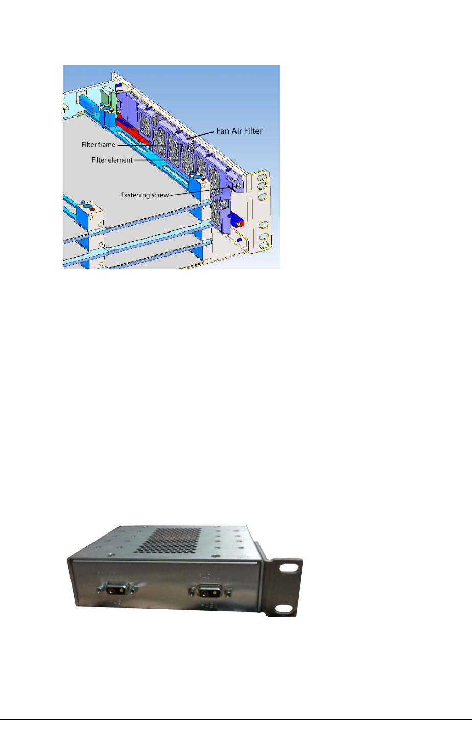
CHAPTER 6INSTALLING THE INU AND INUE
Figure 44. Location of Fan Air Filter in INUe
Power Line Filter Option
An external DC power line filter option is available and must be installed with an INU/INUe
for NEBS compliance. It ensures Eclipse meets EMI requirements specified within
Telcordia GR-1089-CORE, Issue 4, June 2006.
It is IRU tall and 140 mm wide (5.5”) and is supplied as a kitset comprising the filter unit,
bracket for left or right-side rack mounting, and a short 2W2 to 2W2 cable for connecting
the filter unit to the NCC or NPC -48 Vdc inputs.
Where an NPC is fitted, two filter units are required, one for the NCC, the other for the
NPC.
The standard power cable supplied with an INU or NPC is re-used as the power input
cable for the filter unit.
Figure 45. Power Line Filter with Bracket
114 JULY 2018 AVIAT NETWORKS
INSTALLING THE INU AND INUE CHAPTER 6
INU/INUe Installation Requirements
Table 14. INU/INUe Installation Requirements
Function/Requirement Priority Details
Restricted access The INU/INUe and its associated dc power supply must be installed in a
restricted access area such as a secure equipment room, closet, or cabinet.
For NEBS compliance this equates to installation of the INU/INUe in a secure,
restricted access central office (CO) or customer premises (CP) location.
Required Rack Space The INU requires 44.5mm (1RU) of vertical rack space and 300mm rack
depth. The INUe requires 89mm (2RU) vertical rack space and 300mm rack
depth.
Ventilation INU/INUe requires unobstructed air passage to each side for ventilation
purposes. There must be a minimum of 50mm (2”) of side spacing to any rack
panels, cable bundles or similar. No space above or below is required for
ventilation purposes.
Maximum Ambient
Temperature
The INU/INUe is specified for a maximum ambient temperature (Tmra) of
+55°Celsius (131° Fahrenheit). Conditions apply - see INU Power Supply on
page 103. The maximum ambient temperature (Tmra) applies to the
immediate operating environment of the INU, which if installed in a rack, is the
ambient applying to its location within the rack.
Physical stability Ensure that adding an INU/INUe to a rack does not adversely impact the
physical stability of the rack.
Power Supply -48 Vdc The INU/INUe PWR modules have the +ve pin on their dc power supply
connector connected to the chassis.
It must be used with a -48Vdc power supply which has a +ve ground; the
power supply ground conductor is the +ve supply to the INU.
The power supply must have an accessible power disconnect device (main
switch).
Power Supply +24 Vdc A PCC is required to provide a +24 Vdc to -48 VDC conversion. The dc power
supply supplying the PCC must be -ve grounded.
There must be no switching or disconnecting devices in the ground conductor
between the dc power supply and the point of connection to a PCC.
D.C. Supply Ground Con-
nection
The INU/INUe has a connection between the earthed conductor of the d.c.
supply circuit and the earthing conductor.
The INU/INUe must be connected directly to the d.c. supply system grounding
electrode conductor or to a bonding jumper from a grounding terminal bar or
bus to which the d.c. supply system grounding electrode is connected.
Switching or disconnecting devices must not be in the grounded circuit
conductor between the d.c. source and the point of connection of the
grounding electrode conductor.
AVIAT NETWORKS JULY 2018 115
CHAPTER 6INSTALLING THE INU AND INUE
Function/Requirement Priority Details
Equipment Location INU/INUe must be located in the same immediate area (such as, adjacent
cabinets) as any other equipment that has a connection between the
grounded conductor of the same d.c. supply circuit and the grounding
conductor, and also the point of grounding of the d.c. system. The d.c. system
shall not be grounded elsewhere.
Location of D.C. Power Sup-
ply
The d.c. supply source for INU/INUe must be located within the same
premises as the INU/INUe.
D.C. Supply Compliance,
Loading and Protection
The dc power supply must be UL or IEC compliant for a SELV output (60Vdc
maximum).
Check to ensure that connection of an INU/INUe to a new or existing dc
supply does not overload the supply, circuit protection devices and wiring.
The INU/INUe and optional NPC module must each be supported from a
dedicated circuit breaker located on their rack power distribution panel.
The circuit breaker(s) should have a rating of:
12A for the INU, and for optional NPC
25A for the INUe, and for optional NPC
15A for the PCC
The circuit breaker(s) must be used as the INU/INUe power
connect/disconnect devices - do not use the front panel connectors as
connect/disconnect devices.
For NEBS compliance the battery return connection is to be treated as a
common DC return (DC-C), as defined in GR-1089-CORE.
Cable routing INU/INUe Cat5, tributary, auxiliary and NMS cables are not to be routed with
any AC mains power lines. They are also to be kept away from any power
lines which cross them.
Chassis Grounding The INU/INUe chassis must be grounded to the station or master ground,
which must be the same ground as used for the dc power supply. Normally
this is achieved by grounding the INU/INUe to the ground bar in its equipment
rack or frame. This bar is most often located to one side of the rack or at rack
top or bottom. In turn, the ground bar is grounded to the station ground.
Fan Air Filter The fan air filter must be installed where the INU/INUe is required to be
NEBS compliant. The filter must be inspected regularly and replaced
when dust laden. Inspection must be at not more than 12 monthly inter-
vals in controlled air environments, or more frequently otherwise.
Power Line Filter The power line filter must be installed where the INU/INUe is required
to be NEBS compliant.
Compact Flash Card
Compatibility
Where plug-in cards such as RAC 60E, RAC 6XE , DAC GE3, are to be
installed into an existing INU, first ensure the Compact Flash card fitted
in the NCC will support the required capacity. See Compact Flash Card
on page 1.
NCC Compatibility Where a higher capacity Compact Flash Card is to be installed into an existing
INU/NCC (NCC V2) to support RAC 60E, RAC 6XE, DAC GE3 operation, first
ensure NCC compatibility with higher capacity Compact Flash cards. See
Compact Flash Card on page 1.
For information on NCC V1 / NCC V2 compatibility refer to Plug-in Installation
Requirements on page 121.
116 JULY 2018 AVIAT NETWORKS

INSTALLING THE INU AND INUE CHAPTER 6
Function/Requirement Priority Details
Intrabuilding
interfaces and cabling
(NEBS Compliance)
Intrabuilding connections to/from Eclipse ports must only be connected via
intrabuilding or unexposed wiring or cabling.
Intrabuilding ports MUST NOT be metallically connected to interfaces that
connect to the OSP or its wiring. These interfaces are designed for use as
intrabuilding interfaces only (Type 2 or Type 4 ports as described in GR-1089-
CORE, Issue 4) and require isolation from the exposed OSP cabling. The
addition of Primary Protectors is not sufficient protection in order to connect
these interfaces metallically to OSP wiring.
Shielded and grounded cables must be used for intrabuilding cabling to/from
Eclipse ports. Cables must be grounded at both ends.
AVIAT NETWORKS JULY 2018 117

CHAPTER 6INSTALLING THE INU AND INUE
Installation
Procedure
lFit the rack mounting ears to the chassis with the grounding stud to left or right
side for the most direct ground wire path to the rack ground bar.
lLocate the INU/INUe in the equipment rack and secure it using four No.12
Phillips dome-head screws from the IDC installation kit.
lGround the INU/INUe from the grounding stud to the rack/frame ground bar
using a length of 4mm2 (AWG12) green PVC insulated stranded copper wire
with a suitably sized ground lug at the ground bar end (supplied by the installer).
The grounding stud accommodates ground cables up to 16 mm2(AWG
6). The stud also provides jack plug connection for a wrist strap.
lIf the equipment rack/frame requires grounding, use 16mm2 (AWG6) wire
from its ground bar to the station ground.
Grounding Safety:
oDo not assume that an existing rack or mounting frame is correctly grounded.
Always check the integrity of the ground connections, which must include a
check through to the master ground for the station, which should be located at
the point of cable entry to the equipment building. Ground wires must provide a
direct, low impedance path to the master ground bar.
oDo not connect other equipment to the same grounding cable as the INU. Each
item of equipment in a rack must be separately grounded to the rack ground
bar.
oThe INU must be located in the same immediate area (adjacent
racks/cabinets) as all other equipment with a (ground) connection to a
common DC supply source.
For NEBS compliance:
oInstall the fan air filter option. Options are available for the IRU INU and IRU
INUe. See FAN Air Filter Option on page 113.
oInstall the NEBS power line filter unit. Install immediately below or above the
INU. Separate filter units are required for the NCC and, where fitted, the NPC.
Use the supplied 2w2 to 2w2 cable to connect the output of the filter unit to the
input of the NCC or NPC.
oTo ground the INU use 16 mm2 (AWG 6) green PVC insulated stranded copper
wire together with a star washer under the grounding screw at the ground-bar
end. Torque the INU grounding post screw to 1.2-1.5 Nm (10-13 in-lbs).
118 JULY 2018 AVIAT NETWORKS

INSTALLING THE INU AND INUE CHAPTER 6
oAll bare conductors must be coated with an appropriate antioxidant compound
before crimp connectors are fitted.
oAll unplated connectors, braided strap, and bus bars must be brought to a
bright finish and then coated with an antioxidant before they are connected. This
does not apply to tinned, solder-plated, or silver-plated connectors and other
plated connection surfaces – but all must be clean and free of contaminants.
oAll raceway fittings must be tightened to provide a permanent low-impedance
path.
lInstall the plug-ins in their assigned slot positions, and check that their front
panels are flush-fitted (not protruding) and held secure by their fasteners.
Ensure unused slots are covered by blanking panels. See See "Plug-in Slot
Configuration", and Plug-in Installation Requirements on page 121.
oIf a FAN air filter is required, fit it prior to inserting the FAN.
oInstall the CompactFlash card in the NCC; insert in the socket on the right
side of the PCB.
lFor an ODU, fit the supplied jumper cable between the RAC and ODU cable, or
where required to a lightning surge arrestor. See Arrestor Installation at
Building Entry on page 1. Secure the cable within the rack/frame using cable
ties or similar. If the jumper cable is too short, make an extension cable. See
Jumper Cables on page 1.
lFor an IRU 600, fit the supplied jumper cable between the RAC and companion
IRU 600 RFU.
lFit the DAC tributary cables. For information on the tributary cable sets, refer to
See "INU/INUe and IDU Connector and Cable Data"
NOTE: For a DAC 16x, ensure correct orientation of the Mini RJ-21
connector before pushing it home. This can be checked by the scalloped
key to one side of the connector. Additionally, a tributary cable supplied
by Aviat Networks will have the cable exiting to the right side when
viewed from the front. Do NOT over-tighten the Mini RJ-21 retaining
screws.
The following steps describe the procedure for installing the power cable and preparing for
power-on. Do not connect the power until all steps have been completed.
lRun the supplied power cable through to the power pick up point, which will
normally be at a circuit breaker panel in the rack. A circuit breaker (or fuse)
should have a capacity of 12A for the INU and a 25A for the INUe, however
these ratings can be adjusted in line with the number of cards installed, and
hence power consumption. For power consumption data, see INU Power
Supply on page 103.
lFor a -48 Vdc supply, connect the blue wire to -48Vdc (live), and the black wire
to ground/+ve. (Power input on the NCC and NPC is polarity protected).
lFor a +24 Vdc supply, connect the blue wire to +24Vdc (live), and the black wire
AVIAT NETWORKS JULY 2018 119

CHAPTER 6INSTALLING THE INU AND INUE
to ground/-ve. (Power input on the PCC is polarity protected).
lMeasure the voltage on the dc power connector.
oFor -48 Vdc operation the voltage should be -48Vdc, +/-2Vdc for a non-battery
floated supply, and nominally -56 Vdc for a battery floated supply. (Limits are -
40.5 to - 60 Vdc).
oFor +24 Vdc operation the voltage should be 24 +/- 2Vdc for a non-battery
floated supply, and nominally 30 Vdc for a battery floated supply. (Operating
limits are 20 to 36 Vdc).
NOTE: This product meets the global product safety requirements for
SELV (safety extra low voltage) rated equipment and the input voltage
must be guaranteed to remain within the SELV limits (60V maximum) in
the event of a single internal fault.
Always check the integrity of the dc power supply to an INU/INUe right to
its source. Never assume that the supply provided to the pick-up point in
a rack is correct.
Eclipse dc power, IF, tributary, auxiliary and NMS cables are not to be
routed with any AC mains power lines. They are also to be kept away
from any AC power lines which cross them.
lCarry out a complete check of the installation. When all is checked and correct,
the INU is ready for power-on.
oIf a PCC is installed, ensure the PCC to NCC/NPC cable is correctly fitted
before power-on.
CAUTION: Once powered up the radio frequency units will be transmitting with the pre-
configured or ex-factory frequency and power settings unless the start-up transmit mute
option has been invoked. (All ODUs/RFUs shipped ex-factory have the transmit-mute set
as the default unless otherwise specified).If frequency and power settings are not
correct, interference can be caused to other links in the same geographical area.
lTurn power on. For -48 Vdc connect the power cable to the NCC, and to the NPC
where fitted. For +24 Vdc operation, connect to the PCC input.
oWhere a power line filter is installed (for -48 Vdc), connect to the filter input.
CAUTION: Do not turn off an INU/INUe within 10 minutes of initial turn-on, or initial turn-
on after a new compact flash card is installed.
CAUTION: 2W2 DC power connectors can be shorted inadvertently if applied at an angle.
Always insert with correct alignment.
CAUTION: Ambient temperatures must not exceed 550C (1310F). If installed in a rack
cabinet, it is the ambient within the cabinet.
The Eclipse INU is ready for configuration and antenna alignment.
120 JULY 2018 AVIAT NETWORKS
INSTALLING THE INU AND INUE CHAPTER 6
Plug-in Installation Requirements
The table below details the plug-in requirements at installation. Unless specified by the
customer, plug-ins will not be installed in an INU/INUe at shipment. Instead, each is
individually packed within the shipping box.
For a description of the plug-ins, see the Eclipse Platform Product Description. For
configuring plug-ins, see Node and Terminal Plug-ins on page 1.
For information on user-interface connector and cable data, refer to INU/INUe and IDU
Connector and Cable Data on page 1.
Table 15. Plug-in Requirements
Function/Requirement Priority Details
Slot Assignment
All slots filled All slots must be filled with either a plug-in or a blanking panel.
Failure to do so will compromise EMC integrity and distribution of
FAN cooling air.
Universal slots
1-4 on an INU
1-6 on an INUe
RAC, DAC, NCM, and AUX plug-ins can be fitted in any universal
slot.
Restricted slots
7-9 on an INUe
DAC, NCM, and AUX plug-ins can be fitted in any restricted slot.
The exceptions are the DAC 155oM, DAC 155eM, and AUX, which
must only be installed in slots 1 to 6 when they are to be configured
to carry/access Eclipse NMS, otherwise they can be installed in
slots 7 to 9.
Dedicated slots The NCC, FAN, and NPC plug-ins have dedicated slots.
Protected RACs INUe Protected RACs (or ring-protected RAC with DAC 155oM) must
only be installed in ‘above and below’ slots as indicated by the red
arrows.
AUX Multiple AUX plug-ins can be installed per INU/INUe.
NPC Only one NPC is required to provide the NCC protection option. An
NPC must be installed in slot 4 of an INU, or slot 10 of an INUe. If
an NPC is not installed in an INU, slot 4 is available as a universal
slot.
Installing / Changing Plug-ins
ESD grounding strap Always connect yourself to the INU/INUe with an ESD grounding
strap before changing or removing a plug-in. Failure to do so can
cause ESD damage to the plug-ins. Avoid hand contact with the
PCB top and bottom.
AVIAT NETWORKS JULY 2018 121
CHAPTER 6INSTALLING THE INU AND INUE
Function/Requirement Priority Details
Finger-grip fasteners Plug-ins must be withdrawn and inserted using their finger-grip
fasteners/pulls. Never withdraw or insert using attached cables,
as damage to the plug-in connector and its PCB attachment can
occur. If not complied with, the Aviat Networks warranty may be
voided.
Do not over-tighten fasteners. Hand-tighten or use only light
screwdriver pressure.
Hot-swappable Plug-ins are hot-swappable.
Removal of an in-service payload plug-in will interrupt its
traffic.
Removal of the NCC will affect all traffic - unless protected by
an NPC.
Removal / replacement of the FAN does not affect traffic.
Engaging backplane
connector
When installing a plug-in, ensure its backplane connector is
correctly engaged before applying sufficient pressure to bring the
plug-in panel flush with the front panel.
Revision time lag When swapping or installing plug-ins, up to 60 seconds can be
required for the INU/INUe to show its revised status via the front
panel LEDs, or via Portal.
EMC integrity Plug-ins and blanking panels are held in place by captive finger-
screws. Ensure the finger-screws are fastened as failure to do so
may compromise EMC integrity and fan cooling.
NCCs
NCC Versions There are two NCC versions: V1 and V2.
NCC V2 is recognized by the 4-port Ethernet NMS assembly, no
front panel fuse holder, and a 2W2C D-series power connector.
NCC V1 (obsolete) has a three port Ethernet NMS assembly, a
front panel fuse holder, and a small two-pin power connector.
The latest software version to support NCC V1 is 5.01.44. If
attempts are made to upgrade an INU with an NCC V1 to 6.0
software, the action will not be executed; the software load will
fail and the NCC will remain at the version it was originally
loaded with.
Operation and inter-operation parameters for these two versions
are as follows:
NCC V1 and NCC V2 can be used within the same network.
NCC V1 is only suitable for the INU. It will not operate in the
INUe. NCC V2 supports both INU and INUe.
NCC V1 only supports the power supply redundancy capability
of the NPC plug-in option. It does not support NPC redundancy
for backplane bus management (bus clock). NCC V2 supports
NPC redundancy for power supply and backplane bus
management.
RACs
122 JULY 2018 AVIAT NETWORKS
INSTALLING THE INU AND INUE CHAPTER 6
Function/Requirement Priority Details
Connecting and
disconnecting the ODU cable
at the RAC
Never disconnect or reconnect an ODU or IRU 600 RFU cable to a
RAC without first turning the power off to the INU or withdrawing
the RAC from the backplane.
NOTE: The ODU /RF U c able provides the power feed to the
ODU /RF U . A rc ing dur ing c onne ction a nd dis co nnec tion at the
RAC on a live RAC can c ause damage to c onnec tor contact
surfaces . Power spikes c aus ed by live connec tion and
disconnec tion may al so c aus e errors on other traffic passing
thro ugh the I NU /I NU e. The onl y ex c eption to l ive
disconnec tion and c onnec tion s hould be for c hecks of
protec ted operation at link c ommis sioning.
Removing RAC from a
powered INU
When removing a RAC from a powered INU, always the disengage
the RAC from the backplane before disconnecting its ODU cable.
Similarly, before inserting an RAC, always reconnect the ODU
cable before engaging the backplane.
RAC combinations for INUe An INUe can be fitted with a maximum of six RACs for one of the
following combinations:
Six non-protected links
One protected/diversity link plus four non-protected links
Two protected/diversity links plus four non-protected links
Three protected/diversity links
Before installing more than four RACs refer to the Power
Consumption and INU Load Maximums in INU Power Supply on
page 103.)
DACs
DAC combinations DACs can be fitted singly or in combination to provide a mix of
interface types and capacities provided they have a common
backplane configuration. The backplane can be set for:
- 2 Mbit/s / E1
- 1.5 Mbit/s / DS1
- 8 Mbit/s / E3
- 3 Mbit/s / DS3
- 155 Mbit/s / STM1/OC3
Mux version DACs allow a mix of interfaces from a common E1 or
DS1 backplane configuration.
Increasing node capacity To achieve a greater node capacity, two or more INUs can be
interconnected via a DAC option.
DAC 16x Mini RJ-21 tributary
cable connector, or DAC
16xV2/V3 HDR tributary cable
connector
Ensure correct orientation of the Mini RJ-21 connector on DAC 16x
before pushing it home. This can be checked by the scalloped key
to one side of the connector. Additionally, a tributary cable
supplied by Aviat Networks will have the cable exiting to the right
side when viewed from the front.
Ensure the connector retaining screws are not over-tightened -
hand tighten or use only light screwdriver pressure.
AVIAT NETWORKS JULY 2018 123

CHAPTER 6INSTALLING THE INU AND INUE
Function/Requirement Priority Details
Line Protection (electrical
DACs)
Line (interface) protection is supported for paired E1/DS1, E3/DS3
and STM1 electrical DACs.
Line Protection (optical
DACs)
Line (interface) / card protection is supported for paired
STM1/OC3 optical DACs.
Interface Protection, Ethernet
DAC GE3
Interface / card protection is supported for paired DAC GE3 cards.
NCM
Installed for E1 or DS1 loop switch operation.
Two are installed for protected operation.
One NCM (1+0 or 1+1) supports up to 8 E1 or DS1 tributaries
directly on HDR connectors.
One or more DAC 16xV2/V3s are additionally installed at sites
requiring access to more than 8 tribs.
Ensure the tributary connector retaining screws are not over-
tightened - hand tighten or use only light screwdriver pressure.
General
Maximum Single Link
Capacity via Eclipse Node
backplane
The maximum drop, through plus drop, or through capacity of an
Eclipse Node comprising one INU/INUe is one of the following,
depending on the backplane setting:
200 Mbit/s / 100x E1
196 Mbit/s / 127xDS1
4xDS3
310 Mbit/s / 2xSTM1/OC3
Maximum Single Link Capa-
city via DPP (RAC
60/60E/6X/6XE DPP con-
nected to DAC GE or DAC
GE3)
366 Mbps for Ethernet traffic or mixed-mode Ethernet with
TDM, using a 256 QAM maximum throughput modulation
profile. This is the link (air) capacity. If all traffic is Ethernet,
the nominal L2 throughput maximum is 365 Mbps (1518
byte frames); the nominal L1 throughput maximum is 465
Mbps (64 byte frames).
Antistatic bags Enclose spare plug-ins, or plug-ins to be returned for service, in
an antistatic bag. When handling a plug-in to or from an antistatic
bag, do so at the INU/INUe and only when you are connected to the
INU/INUe via an ESD ground strap.
Spare blank panels Keep any removed blanking panels for future use.
124 JULY 2018 AVIAT NETWORKS

USER MANUAL
Appendix A. Antennas certified for use
with IRU 600v4 at 5.8GHz
The following table lists all the antennas certified for use with IRU 600v4 at 5.8GHz.
Manufacturer Part Number Antenna Gain
(dBi)
Antenna Size ft
(meters) Antenna Type
RFS MA0528-19AN 19 0.5 Flat panel
RFS MA0528-23AN 23 1 Flat panel
RFS MA0528-28AN 28 2 Flat panel
RFS SPF2-52CN1S 28.5 2 (0.6) Parabolic
RFS SPF3-52CN1S 32 3 (0.9) Parabolic
RFS SPF4-52CN1S 34.4 4 (1.2) Parabolic
RFS SPF6-52CN1S 38.1 6 (1.8) Parabolic
RFS SDF3-52CN1S1 32 3 (0.9) Parabolic
RFS SDF4-52CN1S1 34.4 4 (1.2) Parabolic
RFS SDF6-52CN1S1 38.1 6 (1.8) Parabolic
RFS UXA6-U57AC 39 6 (1.8) Parabolic
RFS UXA8-U57AC 41.6 8 (2.4) Parabolic
RFS PADX6-U57AC1S1R 38.9 6 (1.8) Parabolic
RFS PADX8-U57AC1S1R 41.4 8 (2.4) Parabolic
RFS PAD6-59BC1S1R 38 6 (1.8) Parabolic
RFS PAD8-59AC1S1R 40.7 8 (2.4) Parabolic
RFS SU6-59By 38.1 6 (1.8) Parabolic
RFS SU4-59By 34.7 4 (1.2) Parabolic
RFS DA6-59BC 38.4 6 (1.8) Parabolic
RFS DA8-59Ay 40.9 8 (2.4) Parabolic
RFS UA8-59Ay 40.9 8 (2.4) Parabolic
RFS SUX6-59By 37.8 6 (1.8) Parabolic
RFS SUX4-59Ay 33.8 4 (1.2) Parabolic
RFS DAX4-59AC 33.8 4 (1.2) Parabolic
RFS DAX6-59BC 38 6 (1.8) Parabolic
RFS DAX8-59Ay 40.7 8 (2.4) Parabolic
RFS UXA4-59Ay 33.8 4 (1.2) Parabolic
RFS UXA6-59Cy 38 6 (1.8) Parabolic
260-668066-001 JULY 2018 125

APPENDIX A, ANTENNAS CERTIFIED FOR USE WITH IRU 600V4 AT 5.8GHZ
Manufacturer Part Number Antenna Gain
(dBi)
Antenna Size ft
(meters) Antenna Type
RFS UXA8-59By 40.6 8 (2.4) Parabolic
RFS PADX6-W59BC1S1R 37.9 6 (1.8) Parabolic
RFS PADX8-W59AC1S1R 40.4 8 (2.4) Parabolic
RFS UXA6-W59BC 38.1 6 (1.8) Parabolic
RFS UXA8-W59AC 40.6 8 (2.4) Parabolic
RFS SC3-W60y 31.5 3 (0.9) Parabolic
RFS SB4-W60y 34.3 4 (1.2) Parabolic
RFS SB6-W60y 38.2 6 (1.8) Parabolic
RFS SCX3-W60y 31.5 3 (0.9) Parabolic
RFS SBX4-W60y 34.3 4 (1.2) Parabolic
RFS SBX6-W60y 38.2 6 (1.8) Parabolic
RFS PA4-W57BC1S1 35.5 4 (1.2) Parabolic
RFS PA6-W57BC1S1 39 6 (1.8) Parabolic
RFS PA8-W57AC1S1 41.5 8 (2.4) Parabolic
RFS PAD6-W57BC1S1R 38.9 6 (1.8) Parabolic
RFS PAD8-W57AC1S1R 41.4 8 (2.4) Parabolic
RFS PADX6-W57AC1S1R 38.7 6 (1.8) Parabolic
RFS PADX8-W57AC1S1R 41.2 8 (2.4) Parabolic
RFS DA6-W57BC 39 6 (1.8) Parabolic
RFS DA6-W57BC 41.5 8 (2.4) Parabolic
RFS UXA6-W57AC 38.9 6 (1.8) Parabolic
RFS UXA8-W57AC 41.4 8 (2.4) Parabolic
CommScope P4F-52/A 34.9 4 Parabolic
CommScope P6F-52/A 37.6 6 Parabolic
CommScope PX4F-52/A 34.9 4 Parabolic
CommScope PX6F-52/A 37.6 6 Parabolic
CommScope P4F-57W/A 35 4 Parabolic
CommScope P6F-57W/A 38.5 6 Parabolic
CommScope P8F-57W 41.2 8 Parabolic
CommScope P10F-57W 42.9 10 Parabolic
CommScope P4-57W/A 35 4 Parabolic
CommScope PL6-57W/A 38.5 6 Parabolic
CommScope PL8-57W 41.2 8 Parabolic
CommScope PL10-57W 42.9 10 Parabolic
CommScope HP4F-57W/A 35 4 Parabolic
126 AVIAT NETWORKS

USER MANUAL
Manufacturer Part Number Antenna Gain
(dBi)
Antenna Size ft
(meters) Antenna Type
CommScope HP6F-57W/A 38.5 6 Parabolic
CommScope HP8F-57W 41.2 8 Parabolic
CommScope HP10F-57W 42.9 10 Parabolic
CommScope HP4-57W/A 35 4 Parabolic
CommScope HP6-57W/A 38.5 6 Parabolic
CommScope HP8-57W 41.2 8 Parabolic
CommScope HP10-57W 42.9 10 Parabolic
CommScope PAR8-59 40.2 8 Parabolic
CommScope PARX8-59 40.2 8 Parabolic
CommScope HX6-6W 39.1 6 Parabolic
CommScope USX6-6W 38.4 6 Parabolic
CommScope HP6-59 37.9 6 Parabolic
CommScope HP8-59 40.8 8 Parabolic
CommScope HP10-59 42.3 10 Parabolic
CommScope HP12-59 44.4 12 Parabolic
CommScope PARX8-59 40.1 8 Parabolic
CommScope PARX10-59 42.4 10 Parabolic
CommScope UHX6-59 38.1 6 Parabolic
CommScope UHX8-59 40.6 8 Parabolic
CommScope UHX10-59 42.6 10 Parabolic
CommScope UHX12-59 44.1 12 Parabolic
CommScope HPX4-59 34.1 4 Parabolic
CommScope HPX6-59 38.1 6 Parabolic
CommScope HPX8-59 40.6 8 Parabolic
CommScope HPX10-59 42.4 10 Parabolic
CommScope PAR8-59 40.1 8 Parabolic
CommScope PAR10-59 42.7 10 Parabolic
260-668066-001 JULY 2018 127

260-668066-001
WWW.AVIATNETWORKS.COM