Aviat Networks ODU600HB Eclipse ODU 600 User Manual Eclipse
Aviat Networks (S) Pte. Ltd Eclipse ODU 600 Eclipse
UserManual.wiki
>
Aviat Networks
>
ODU600HB User Manual
>
Installation Manual
Contents
1.
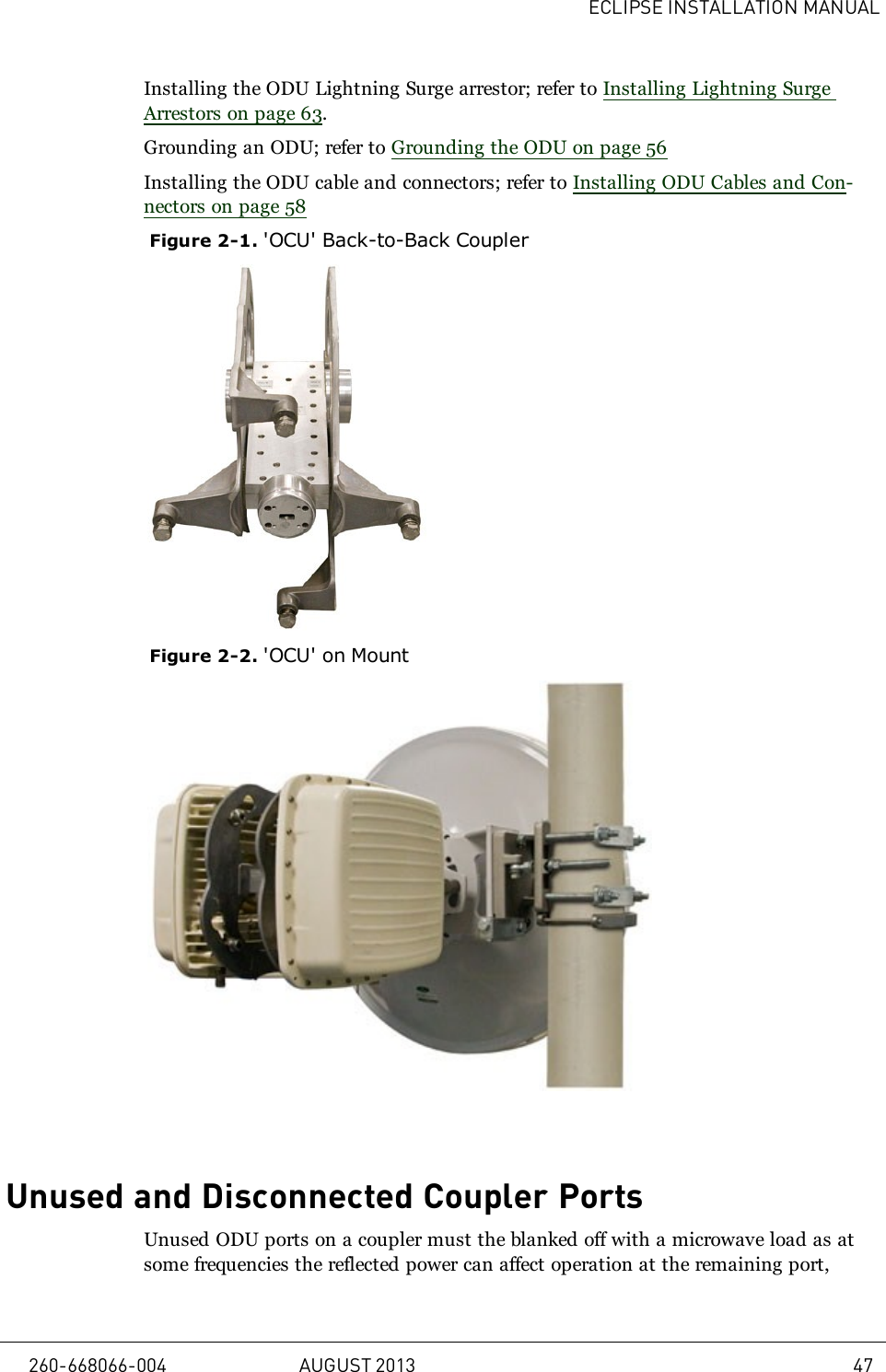
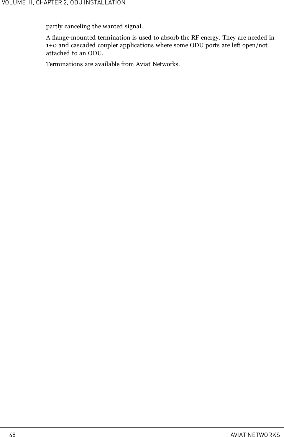
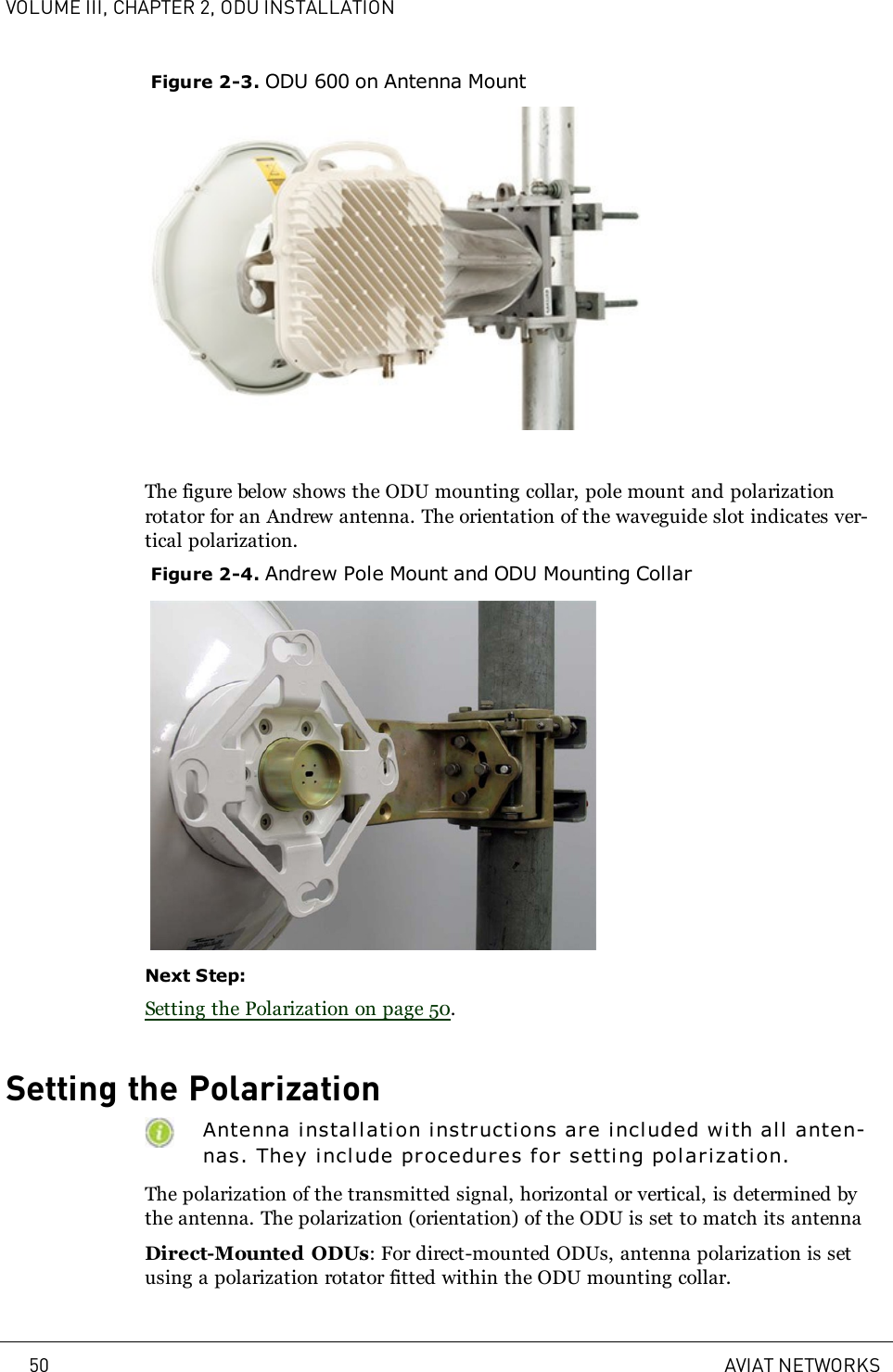
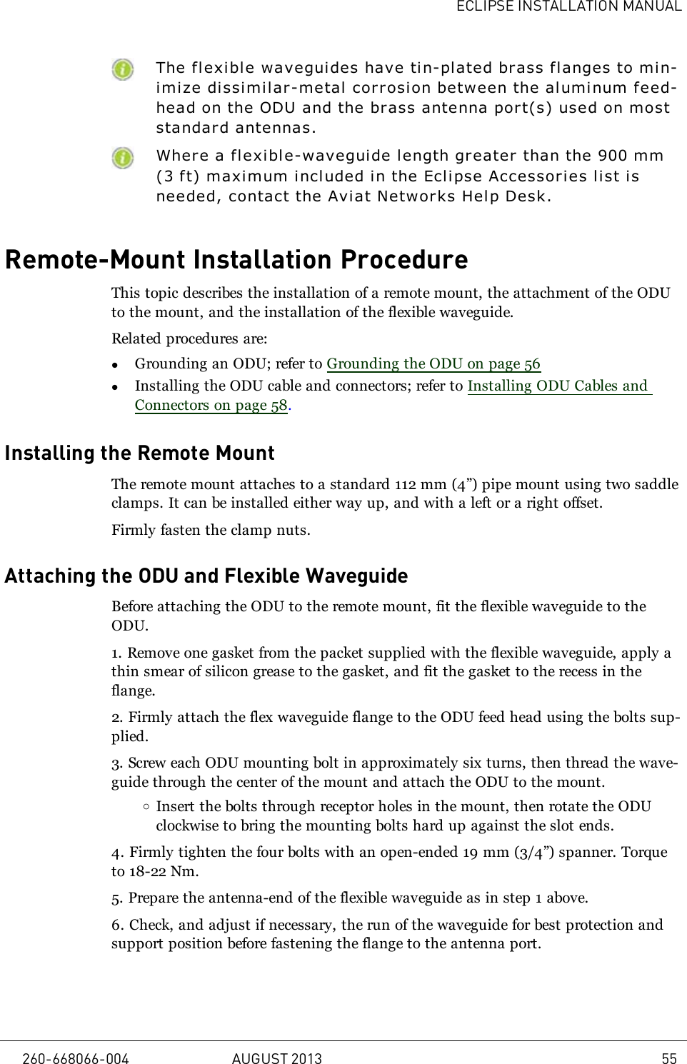
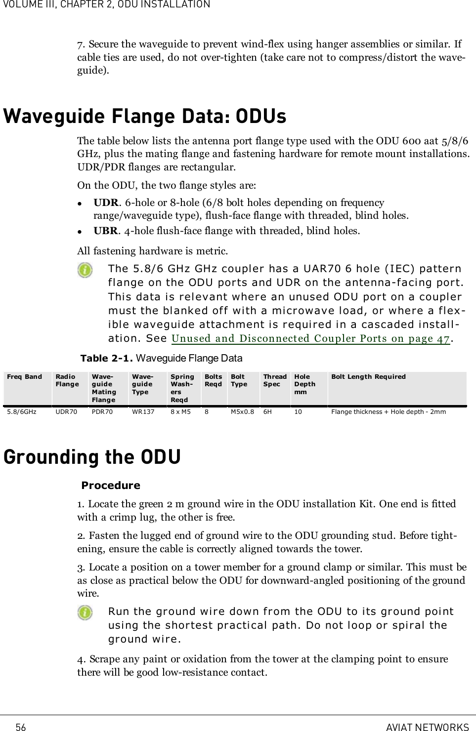
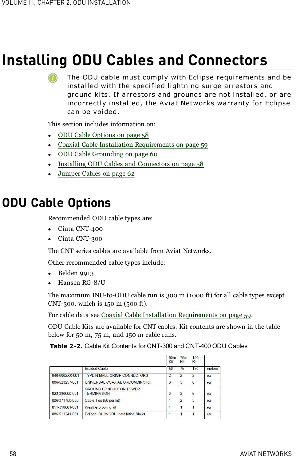
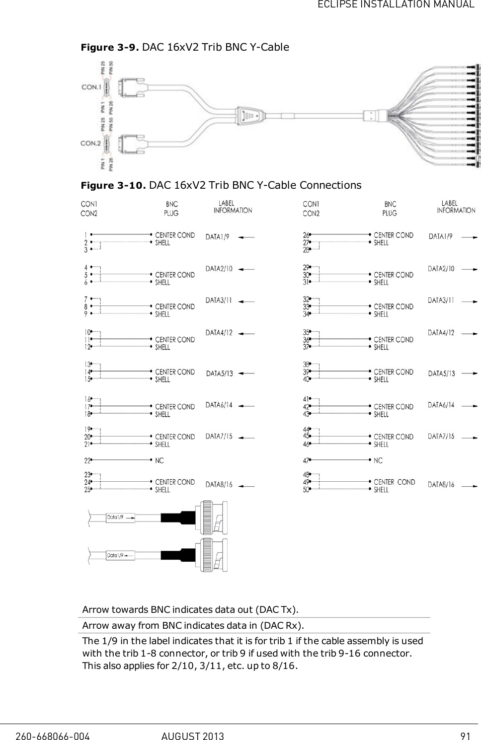
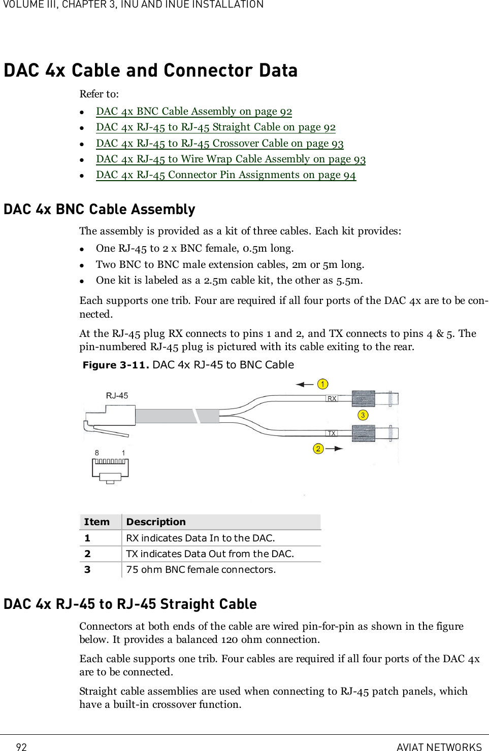
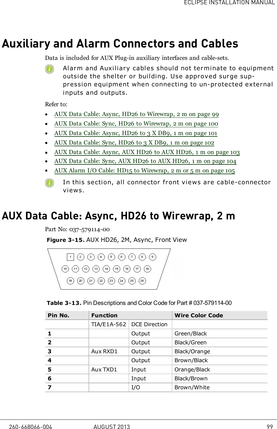
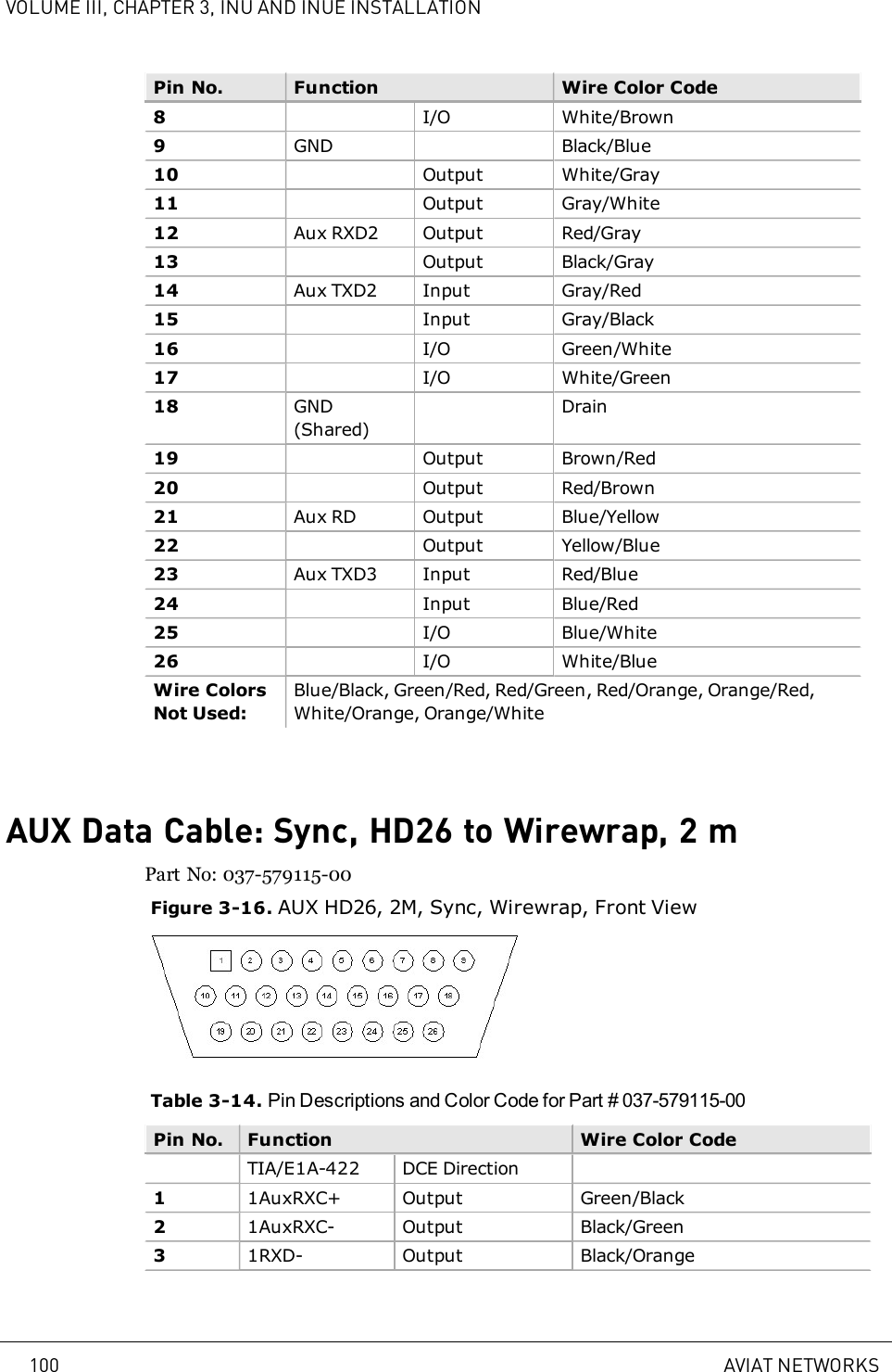
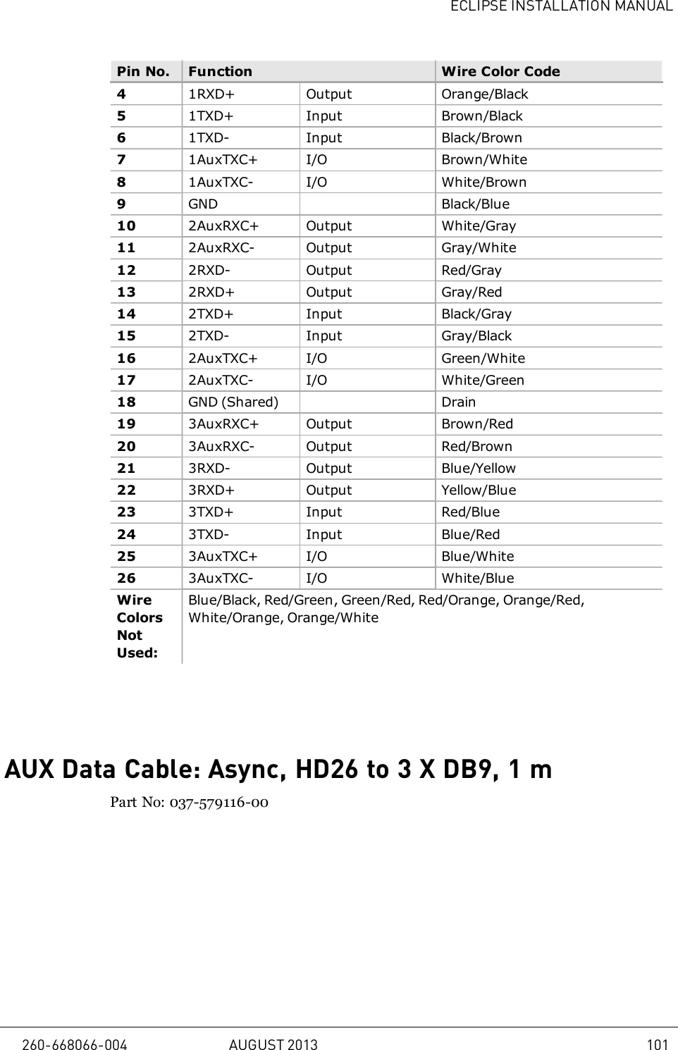
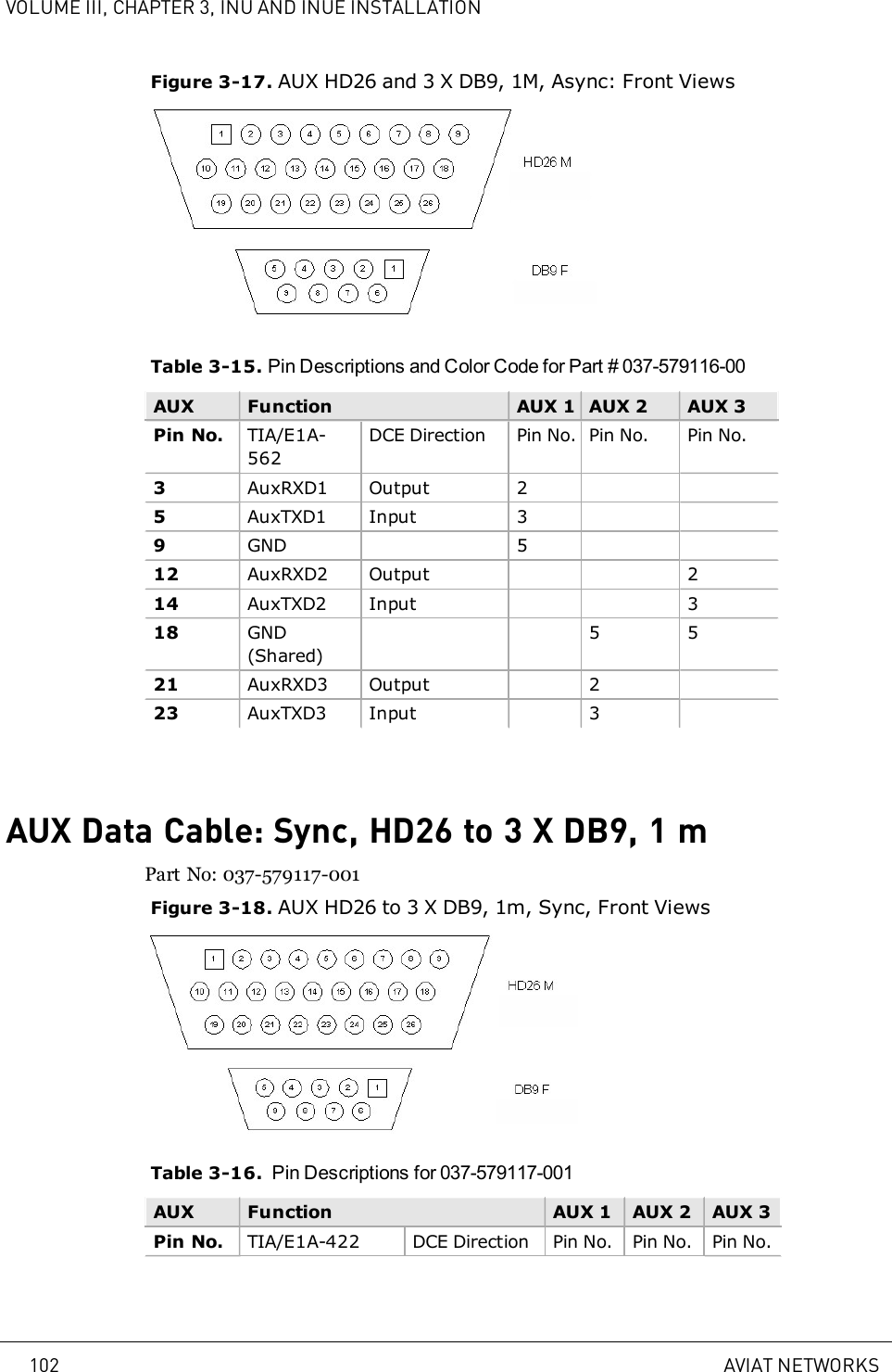
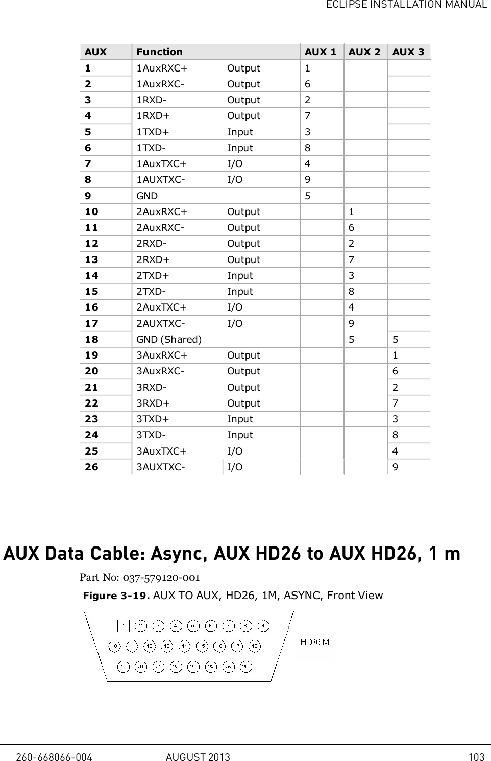
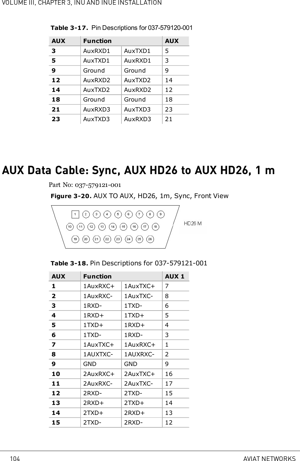
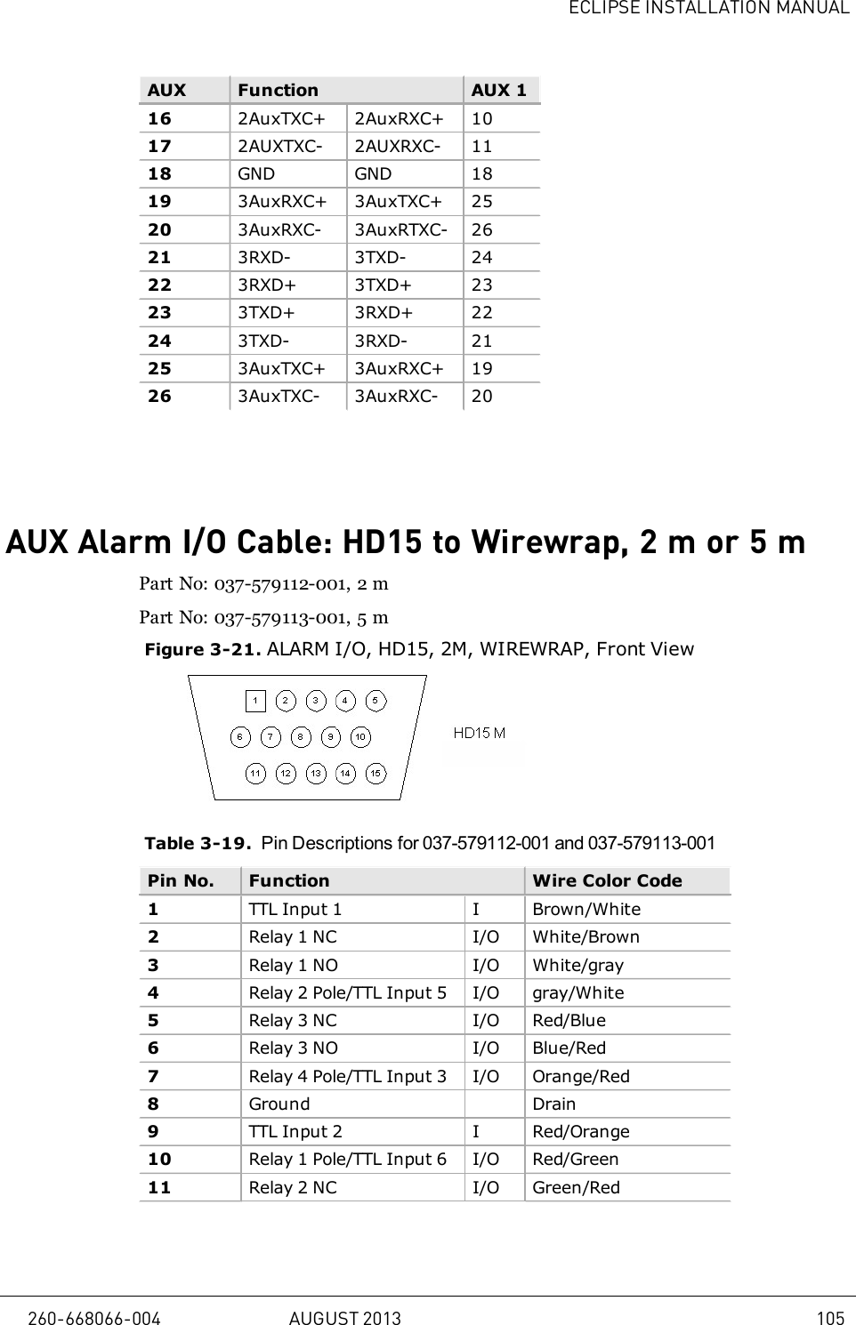
Installation Manual
2.
User Manual
Installation Manual
Navigation menu
Upload a User Manual
Namespaces
Wiki Guide
HTML
PDF
Info
Views
User Manual
Discussion / Help
Navigation