Aviat U S 3160-37A WiMAX CPE User Manual HSX StarMAX 3100 User
Aviat U.S., Inc. WiMAX CPE HSX StarMAX 3100 User
User manual

Microwave Digital Radios
260-668104-001
StarMAX™
3100 SERIES SUBSCRIBER STATION USER MANUAL

StarMAX™ 3100 Series
Subscriber Station User
Manual
Release 4.1.1

ii Harris Stratex Networks
StarMAX™ 3100 Series Subscriber Station User Manual
260-668104-001 December 2009
This manual incorporates features and functions provided with the StarMAX™ 3100 Series, Release
4.1.1, (GA Preliminary Draft).
Copyright © 2009 by Harris Stratex Networks, Inc.
All rights reserved. No part of this publication may be reproduced, transmitted, transcribed, stored in a
retrieval system, or translated into any language or computer language, in any form or by any means,
electronic, magnetic, optical, chemical, manual or otherwise, without the prior written permission of
Harris Stratex Networks Inc. To request permission, contact techpubs@hstx.com.
Warranty
Harris Stratex Networks makes no representation or warranties with respect to the contents hereof and
specifically disclaims any implied warranties or merchantability or fitness for any particular purpose.
Further, Harris Stratex Networks reserves the right to revise this publication and to make changes from
time to time in the content hereof without obligation of Harris Stratex Networks to notify any person of
such revision or changes.
Safety Recommendations
The following safety recommendations must be considered to avoid injuries to persons and/or damage
to the equipment:
1. Installation and Service Personnel: Installation and service must be carried out by authorized
personnel who have the technical training and experience necessary to be aware of any hazardous
operations during installation and service, and of measures to avoid any danger to themselves, to
any other personnel, and to the equipment.
2. Access to the Equipment: Access to the equipment in use must be restricted to service personnel
only.
3. Safety Norms: Local safety regulations must be used if mandatory. Safety instructions in this
document should be used in addition to the local safety regulations. In the case of conflict between
safety instructions stated in this manual and those indicated in local regulations, mandatory local
norms will prevail.
4. Service Personnel Skill: Service personnel must have received adequate technical training on
telecommunications and in particular on the equipment this manual refers to.
Trademarks
All trademarks are the property of their respective owners.

260-668104-001 December 2009 iii
StarMAX™ 3100 Series Subscriber Station User Manual
Contact Information
Sales and Sales Support:
For sales information, contact one of the Harris Stratex Networks headquarters, or find your regional
sales office at http://www.harrisstratex.com/contact.
Customer Service:
For customer service, contact one of the regional Technical Help Desks listed below.
Or you can contact your local Harris Stratex Networks office. Contact information is available on our
website at: www.harrisstratex.com/support/customer/.
Corporate Headquarters
North Carolina, USA International Headquarters
Singapore
Harris Stratex Networks, Inc.
Research Triangle Park
637 Davis Drive
Morrisville, North Carolina 27560
United States
Phone: + 1 919-767-3230
Fax: + 1 919-767-3233
Toll Free for Sales Inquiries:
+ 1 888-HSTX-NOW (888-478-9669)
Harris Stratex Networks (S) Pte. Ltd.
17, Changi Business Park Central 1
Honeywell Building, #04-01
Singapore 486073
Phone: +65 6496 0900
Fax: + 65 6496 0999
Sales Inquiries:
+1-321-674-4252
Americas Technical Help
Desk EMEA Technical Help Desk Asia Pacific Technical Help
Desk
Harris Stratex Networks
120 Rose Orchard Way
San Jose, CA 95134
U.S.A.
Harris Stratex Networks
4 Bell Drive
Hamilton International
Technology Park
Blantyre, Glasgow, Scotland
G72 0FB
United Kingdom
Harris Stratex Networks
Bldg 10, Units A&B
Philexcel Industrial Park
M. Roxas Hi-way
Clark Freeport Zone
Philippines 2023
Phone:+1 210 561 7400
Toll-free in US:
+1 800 227 8332
Fax: +1 408 944 1683
Phone:+44 1698 714 073
Fax: +44 1698 717 204
Phone:+63 45 599 5192
Fax: +63 45 599 5196
TAC.AM@hstx.com TAC.EMEA@hstx.com TAC.APAC@hstx.com

iv Harris Stratex Networks
FCC Notices
1. The StarMAX Subscriber Station must be professionally installed and maintained.
2. This equipment has been tested and found to comply with the limits for a Class B digital device,
pursuant to Part 15 of the FCC rules.
3. Notes specific to the 3.65 – 3.675GHz band:
•The StarMAX 3160-37 Subscriber Station complies with FCC CFR47, Part 90, Subpart Z.
•For FCC CFR47, Part 90, Subpart Z, StarMAX operation is restricted to the 25MHz band 3.65GHz
– 3.675GHz.
•To ensure compliance with the FCC RF exposure requirements, a minimum distance of 25cm must
be maintained between the subscriber station antenna and any persons whilst the unit is
operational at 5MHz and 34cm for 10MHz operation. This calculation is based on the EIRP limits
within Part 90, Subpart Z.
•The 3160-37 Subscriber Station has been tested and certified to FCC CFR47, Part 90, Subpart Z
with an integral antenna with a gain of 14dBi.
•FCC CFR47, Part 90, Subpart Z, applies strict limitations on EIRP. 5MHz operation has an EIRP
limit of 5W and 10MHz operation has an EIRP limit of 10W. The StarMAX Subcriber Station is not
field programmable so the power is set during production. Model 3160-37-14-05 should be used for
all installations within the United States.
260-668104-001 December 2009 v
StarMAX™ 3100 Series Subscriber Station User Manual
WARNING
Making adjustments and/or modifications to this equipment that are not in
accordance with the provisions of this instruction manual or other
supplementary documentation may result in personal injury or damage to
the equipment, and may void the equipment warranty.
AVERTISSEMENT
Tout réglage ou modification faits à cet équipement hors du cadre édicté
par ce guide d’utilisation ou par toute autre documentation supplémentaire
pourraient causer des blessures ou endommager l’équipement et peut
entraîner l’annulation de sa garantie.
WARNUNG
Die an diesen Geräten gemachte Einstellungen und/oder Änderungen,
welche nicht gemäß dieser Bedienungsanleitung, oder gemäß anderen
zusätzlichen Anleitungen, ausgeführt werden, können Verletzungen oder
Materialschäden zur Folge haben und eventuell die Garantie ungültig
machen.
ATENCIÓN
Llevar a cabo ajustamientos y/o modificaciones a este equipo, sin seguir
las instrucciones provistas por este manual u otro documento adicional,
podría resultar en lesiones a su persona o daños al equipo, y anular la
garantía de este último.

vi Harris Stratex Networks

260-668104-001 December 2009 v
Contents
CHAPTER 1, OVERVIEW OF THE STARMAX™ 3100 SERIES SUB-
SCRIBER STATIONS
Abbreviations & Definitions ............................................................................ 1-1
Conventions................................................................................................. 1-3
Introducing the StarMAX™ 3100 Series............................................................ 1-4
About the StarMAX™ 3100 Series Stationary Subscriber Stations ........................ 1-5
Subscriber Station Features ....................................................................... 1-6
Subscriber Station HTML GUI Manager......................................................... 1-6
CHAPTER 2, QUICK INSTALLATION OF THE STARMAX™ 3100 SE-
RIES STATIONARY SUBSCRIBER STATIONS
Installation of the StarMAX™ 3120 Subscriber Station ....................................... 2-1
Installation of the StarMAX™ 3160 Subscriber Station ....................................... 2-3
Mounting the Subscriber Station on a Pole.................................................... 2-3
Mounting the StarMAX™ 3160 on a Wall ...................................................... 2-4
Connecting the Equipment ......................................................................... 2-5
PoE Injector/Splitter.................................................................................. 2-6
Sealing the StarMAX™ 3160 PoE Injector ..................................................... 2-9
CHAPTER 3, ANTENNA ALIGNMENT
CHAPTER 4, SUBSCRIBER COMMISSIONING
Required Information .................................................................................... 4-1
Configuring Basic Parameters ......................................................................... 4-1
Aligning the Subscriber Unit Antenna............................................................... 4-2
Operational Verification of the Subscriber Station .............................................. 4-2
Verifying Data connectivity......................................................................... 4-3
CHAPTER 5, CONFIGURING YOUR COMPUTER (MS WINDOWS)
Setting the IP Address................................................................................... 5-1
Verifying the Connection ................................................................................ 5-3
Setting the Password..................................................................................... 5-5
CHAPTER 6, SUBSCRIBER STATION HTML GUI
Ethernet Link Down....................................................................................... 6-1
HTML GUI Introduction .................................................................................. 6-2
Authentication (Login/Password)................................................................. 6-2
System Info Tab ....................................................................................... 6-2
Basic Settings .......................................................................................... 6-4
Advanced Settings Tab .............................................................................. 6-5
Antenna Status Tab................................................................................. 6-10

vi
Harris Stratex Networks
Interface Statistics Tab............................................................................ 6-11
Rebooting Tab........................................................................................ 6-12
CHAPTER 7, NETWORK ADDRESS TRANSLATION (NAT)
Enabling NAT................................................................................................ 7-2
Operating Modes (L2, 1:N, N:N) ..................................................................... 7-2
Operating Mode Switching.............................................................................. 7-3
L2 to NAT Operating Mode ......................................................................... 7-3
NAT to L2 Operating Mode ......................................................................... 7-3
Provisioning Server Changes .......................................................................... 7-4
Interfaces and IP Address Assignment ............................................................. 7-4
N:N NAT Translations..................................................................................... 7-4
DHCP Server Configuration ............................................................................ 7-5
Access Control.............................................................................................. 7-5
DMZ ........................................................................................................... 7-6
VLAN traffic ................................................................................................. 7-6
INDEX
260-668104-001 December 2009 1-1
Chapter 1. Overview of the
StarMAX™ 3100 Series
Subscriber Stations
This chapter gives you an overview of the StarMAX™ 3100 Series Stationary
Subscriber Stations. It covers the following topics:
• Introducing the StarMAX™ 3100 Series
• Brief description of the StarMAX™ 3100 Series Stationary Subscribers
• Subscriber Station HTML GUI management
Abbreviations & Definitions
Abbreviations Description
ACB ATCA carrier board
BE Best Effort
BS Base Station
CINR Carrier-to-Interface plus Noise Ratio
CIR Committed Information Rate
CLI Command Line Interface
CPE Customer Premises Equipment
DC Direct Current
DHCP Dynamic Host Configuration Protocol
DMZ De-Militarized Zone
EIRP Equivalent Isotropic Radiated Power
EMS Element Management System
FEC Forward Error Correction
GND Ground
GPS Global Positioning System
IDU Indoor Unit
IF Intermediate Frequency
IPMI Intelligent Platform Management Interface

1-2 Harris Stratex Networks
Chapter 1. Overview of the StarMAX™ 3100 Series Subscriber Stations
LED Light Emitting Diode
LVDS Low Voltage Data Signal
MAC Medium Access Control
MIB Management Information Base
MPU Main Processor Unit
NAPT Network Address Port Translation
NAT Network Address Translation
NMS Network Management System
Nrt-PS Non Real Time Polling Services
ODU Outdoor Unit
PLL Phase Locked Loop
PMP Point To Multipoint
POE Power Over ethernet
POST Power On Self Test
PPS Pulses Per Second
PS Provisioning Server
PSU Power Supply
RF Radio Frequency
RO Read Only
R/W Read/Write
RSSI Receive Signal Strength Indicator
SELV Safety Extra Low Voltage
SFP Small Form-factor Pluggable
SNMP Simple Network Management Protocol
SoC System on Chip
SS Subscriber Station
STC/MRC Space Time Coding / Max. Ratio Combining
TDM Time Division Multiplexing
TTL Transistor-Transistor Logic
VEE Virtual End-to-End
VLAN Virtual Local Area Network
WEEE Waste Electronic Electric Equipment
Abbreviations Description
260-668104-001 December 2009 1-3
StarMAX™ 3100 Series Subscriber Station User Manual
Conventions
The following conventions are used in the document to help you to identify special
terms.
The Note format is used for clarification or to point out specific text or
instructions in the procedure or description.
The Caution format is used for a Warning or a Caution. The
information that follows alerts personnel to possible damage to
equipment or interruption of service, or a violation of a legal
requirement.
Convention Usage Example
Bold The following screen
elements:
Button
List
Drop-down menu
Click OK.
Courier
New Computer output text HSX_bs#configure access-list 2
permit 11:22:33:44:55:66
00:00:00:00:00:00 22:33:44:55:66:77
00:00:00:00:00:00
Courier
Bold User input text >HSX_bs#exit
Courier
Italic Variable in command that
you may replace with other
values, as required
To make a new directory, enter:
prompt> mkdir new_directory_name
Italic Description of figures and
tables, Book title and
emphasis, Cross References
ProductCodes
Refer to User Manual for more information.
< > Mandatory parameters HSX_bs# show card <unit number>
[ ] Optional parameters HSX_bs# configure ip address <ip-address>
[subnet mask]
| Mutually exclusive choices in
a command or a code
HSX_bs#reboot 1|2|3
1-4 Harris Stratex Networks
Chapter 1. Overview of the StarMAX™ 3100 Series Subscriber Stations
The Stop format indicates a pause in the procedure to perform some
other task. The procedure continues once you have completed the other
task.
Introducing the StarMAX™ 3100 Series
Harris Stratex Networks' StarMAX™ 3100 Series Subscriber Stations (SS) are fully
compliant and certified with the IEEE 802.16e-2005 standards and conform to
WiMAX forum Wave 2 inter-operability specifications. They are matched to the
frequencies and WiMAX enhanced features supported by the Harris Stratex Networks
Base Station (BS) system. When deployed in networks based on the StarMAX™ Base
Station, they provide optimal performance in line-of-sight (LOS), near line-of-sight
(NrLOS) as well as non-line-of-sight (NLOS) applications. The Subscriber Station
offers market leading performance through the use of intelligent antenna systems and
advanced WiMAX features.
The system uses S-OFDMA radio technology, which is robust in adverse channel
conditions and enables NLOS operation. This helps in easy installation, improves
coverage, and maintains a high level of spectral efficiency. Modulation and coding can
be adapted per burst, helping to achieve the balance of robustness and efficiency, based
on the prevailing link conditions.
StarMAX™ 3100 Series Subscriber Stations support a wide range of network services,
including Internet Access and Voice over IP. A variety of other choices are also available
to meet the requirements of different environments, including residential, SOHO,
SME, large enterprise and multi-tenant customers while able to support fixed, nomadic
and mobile services.
The StarMAX™ 3100 Series of Subscriber Stations is currently available in the 2.3-2.4,
2.5-2.7 GHz, 3.4-3.6 GHz, and 3.6-3.8 GHz frequency bands, and also of various signal
send/receive strengths. The actual operating frequencies used by the system can be
configured by software according to the applicable radio regulations, license conditions
and specific deployments.
3160 CPE must be professionally installed. It is up to the installer to set
the Frequency of the CPE (frequency scanning list). For NA market, we
do not have to define a SKU that limits the frequency but we do need a
FRU that limits the power. In Canada, we need to limit both the
frequency and power. Both NA and Canada follow the same EIRP limits
across the 50 MHz frequency band (1 watt per MHz).
260-668104-001 December 2009 1-5
StarMAX™ 3100 Series Subscriber Station User Manual
About the StarMAX™ 3100 Series Stationary
Subscriber Stations
The Subscriber Station installed at the customer premises provides data connectivity
through the Base Station. Equipment provides high reliability and provides a platform
for wide range services. Subscriber side WiMAX functionality on PHY and MAC layer
is implemented. The Subscriber Station provides the data bridging functionality, traffic
shaping and classification through the 10/100 BaseT Ethernet ports.
Figure 1-1. Model of SS
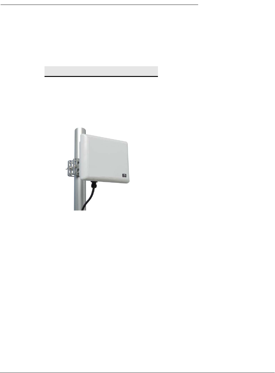
•The StarMAX™ 3160 Subscriber Station is an outdoor version, designed for a
full outdoor operation. It comes with an integrated antenna which is located under
the cover of the unit. The Subscriber Station has an installed beeper and only a
CAT5e cable to the rooftop outdoor unit for effortless installation and alignment. The
Subscriber Station is cost-effective and high performance solution for business and
residential users, requiring a longer range and throughput of an outdoor unit.
StarMAX™ 3160
WiMAX 16e outdoor SS with an
integrated antenna

1-6 Harris Stratex Networks
Chapter 1. Overview of the StarMAX™ 3100 Series Subscriber Stations
Subscriber Station Features
• IEEE 802.16e Wave 2 ready, MIMO 2x2 A/B Mobile WiMAX compliant Subscriber
Station.
• DHCP – IP address assignment for Subscriber Station for remote provisioning.
• Automatic Scanner Channel application. This feature helps the Subscriber Station to
connect to the Base Station with the best RSSI and CINR values among the available
Base Stations.
• Over-the-air fail-safe download of software upgrades.
• Automatic Software upgrade over the TFTP and FTP server on a Subscriber Station
synchronizing with the Base Station after a reboot, software running on the
Subscriber Station is checked with the software available on the TFTP server.
Software upgrade is done if the TFTP server software is different.
• Remote Software upgrade over the TFTP or FTP. Subscriber station software
upgrade can be performed from the CLI over the TFTP. The Subscriber Station
software is obtained from the TFTP server.
• Post-Power on Self test is done to check the basic Subscriber Station system integrity
in terms of on-board hardware components (e.g. memory).
• Packet classification (data, voice) based on VLANs. Subscriber Station provides
functionality to classify the traffic based on a Virtual LAN for Security, QoS etc.
•Packet Filtering based on L2, L3 and L4 parameters.
• CLI (via Telnet) access for debugging and configuration. Command Line Interface
provides standard system command parsing and execution for configuration and
monitoring purposes.
• Transparent VLAN tagging at the Subscriber station in the uplink direction to the
base station and untagging in the downlink direction to the CPE devices.
• Subscriber Station HTML GUI provides the Web service for the Subscriber Station
configuration with respect to the scanner channel, the IP address, a display of the
Subscriber Station radio parameters, and the antenna status.
Subscriber Station HTML GUI Manager
The Subscriber Stations with software revisions 4.0 and newer can be managed
through a web based application called the Subscriber Station HTML GUI (see
Subscriber Station HTML GUI on page 6-1 for details). It enables management of
the Subscriber Station as well as monitoring of the RF signal levels (RSSI and CINR).
260-668104-001 December 2009 2-1
Chapter 2. Quick Installation of
the StarMAX™ 3100 Series
Stationary Subscriber Stations
This chapter covers the quick installation of the StarMAX™ 3100 Series Subscriber
Stations:
•StarMAX™ 3160
To install and start using the StarMAX™ 3100 Series Subscriber Station quickly you,
will need the following items:
• A StarMAX™ 3100 Series Subscriber Station.
• A longer Ethernet cable (straight) in cases where the enclosed cable is too short.
• For the StarMAX™ 3160 - a screwdriver, a pair of tongs, a spanner, a pole, drilling
equipment and other accessories.
• A PC that is configured with the following:
• An Ethernet interface
• Microsoft Windows®
Unit must be supplied by Power over Ethernet adapter complying with
Limited Power Source requirements according IEC 60950-1 with rated
output voltage 48Vdc.
2-2 Harris Stratex Networks
Chapter 2. Quick Installation of the StarMAX™ 3100 Series Stationary Subscriber Stations
Installation of the StarMAX™ 3160
Subscriber Station
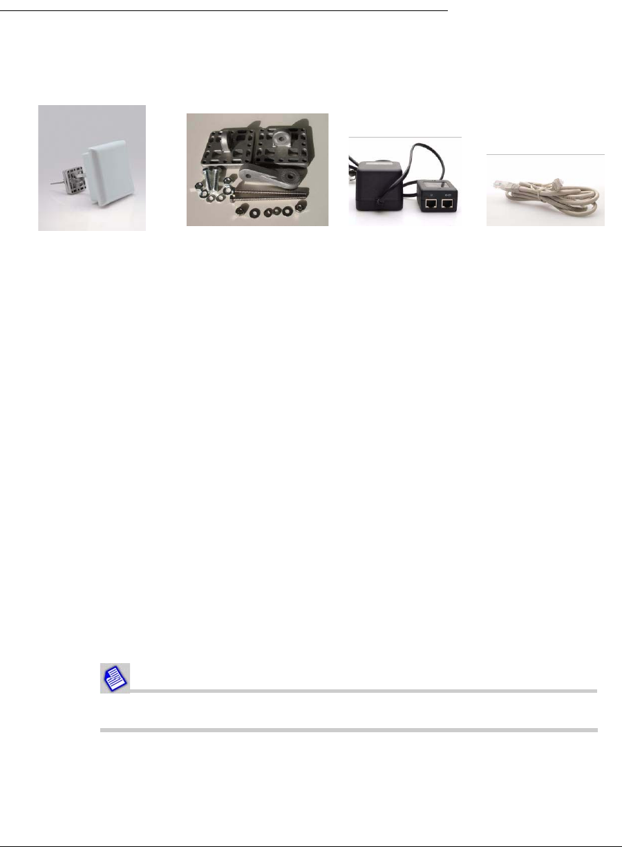
Ensure that the package contains the items shown in the following figure:
Figure 2-1. The StarMAX™ 3160 Package Contents
Mounting the Subscriber Station on a Pole
This section provides the installation process guidelines for the existing pole
installation outside of the customer premises. The most suitable location for a pole is
such that the Subscriber Station can be rotated 360 degrees in a horizontal direction
and aligned for about +/- 5 degrees in the vertical direction (when the pole is vertical
and vice versa when the pole is horizontal), to be able to align the antenna correctly. If
the best direction towards the closest Base Station is already known, such a wide angle
for the alignment is not needed. Recommended pole diameter is 40 mm and the
required pole length is 1.25 m.
There are two possibilities of mounting a Subscriber Station on a pole:
• Vertical mounting on a pole (two diameters)
• Horizontal mounting on a pole (two diameters)
Make sure that the pole is mounted firmly enough. If the pole is mounted at the highest
point of the building, a proper grounding must be installed for the pole and at least 30
cm of the pole should be left above the top of the Subscriber Station. That ensures that
in case of a lightning strike electric discharge hits the pole and is taken directly to the
ground.
The antenna can be mounted on a pole with a diameter of 40-65 mm.
a) The 3160 outdoor
Subscriber Station
b) Mounting kit c) Power over
Ethernet Injector
(PHIHONG PSA
16U-480)
d) RJ-45 Network
Cable
260-668104-001 December 2009 2-3
StarMAX™ 3100 Series Subscriber Station User Manual
Mounting Bracket Attachment
There are several options of mounting the Subscriber Station (wall mounting, thick and
thin pole mounting, grid mounting etc.). For installing the Subscriber Station on a pole,
please follow the steps described below.
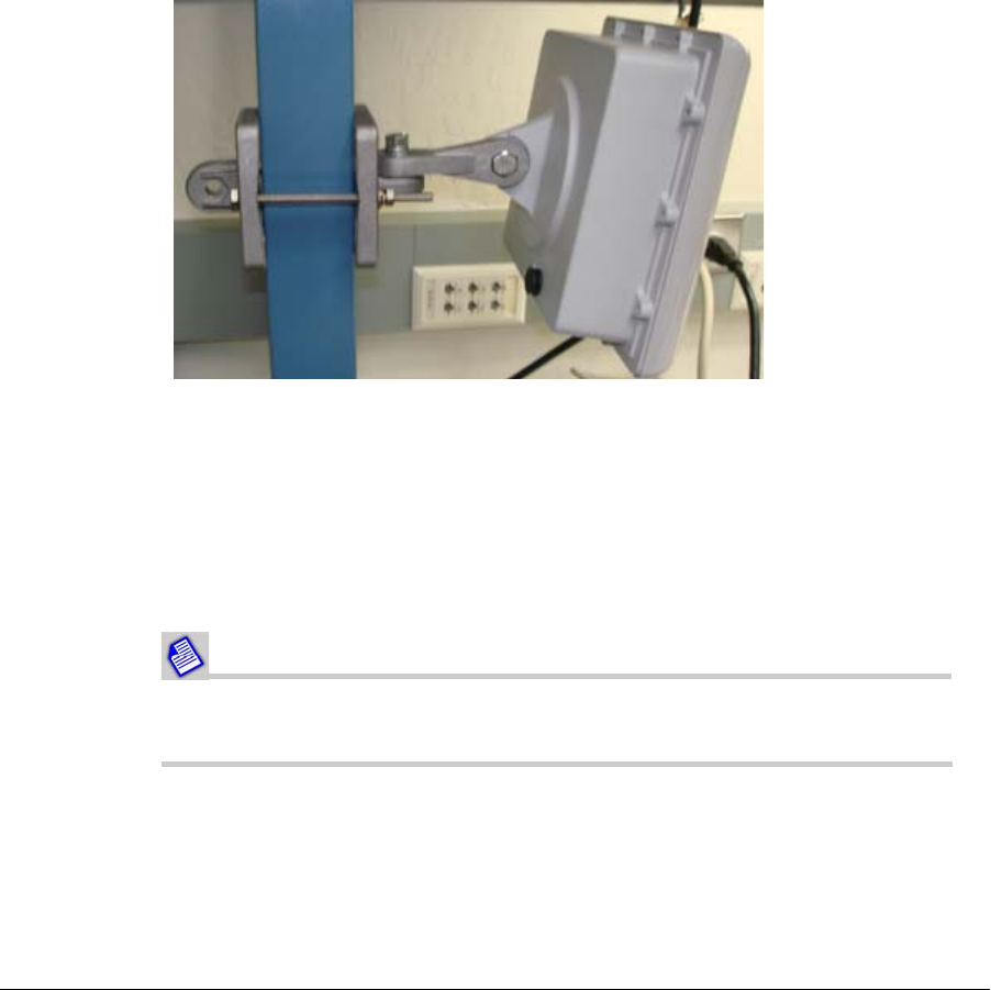
1. Attach the bracket transition to the base bracket of the enclosure as shown in
Figure 2-2.
2. Mate the knurled surfaces so that both items are tightened together.
3. The bolt head should be positioned in the socket of the base bracket, while the nut,
the spring washer and the flat washer should be placed on the flat surface of the
bracket transition. Tighten up the screw with a torque of 24 Nm. Attach the wall
mounting flange on the other side of the transition bracket by using the same
method as the above.
Figure 2-2. Subscriber Station mounting assembly
Mounting the StarMAX™ 3160 on a Wall
This section provides guidelines for the installation of the Subscriber Station on a wall
outside of the customer premises. At first an appropriate location on a wall has to be
chosen. It has to be easily accessible and located as high as possible, the surface has to
be flat and firm, and orientated approximately in the direction of the base station.
Usually the vertical movement of a SS on a wall is very limited.
When mounted on the wall, the mounting kit provides the antenna with
up to a 40° tilting possibility in a horizontal and in a vertical direction.
The procedure for fixing the Subscriber Station on a wall is similar to the procedure
described above, except that the upper part is not necessary.
2-4 Harris Stratex Networks
Chapter 2. Quick Installation of the StarMAX™ 3100 Series Stationary Subscriber Stations
Connecting the Equipment
The unit should be mounted with the female RJ45 connector pointed
downwards and never upwards. If it is necessary to mount the ODU
where the RJ45 connector has to be mounted parallel to the ground, a
service loop needs to be added when attaching the cable to the RJ45
connector.
1. Connect the Network Cable to the RF+DC port on the POE Module.
2. Connect the RJ-45 Network Cable to the RF port on the POE Injector.
3. Connect the other end of the RJ-45 Network Cable to the RJ-45 port of your
computer's Ethernet card or adapter or the network equipment.
4. Connect the POE Injector to a standard electrical outlet.
The POE cable is not provided with the Subscriber Station so you
should take care of the proper connector pinout when preparing
the cable.
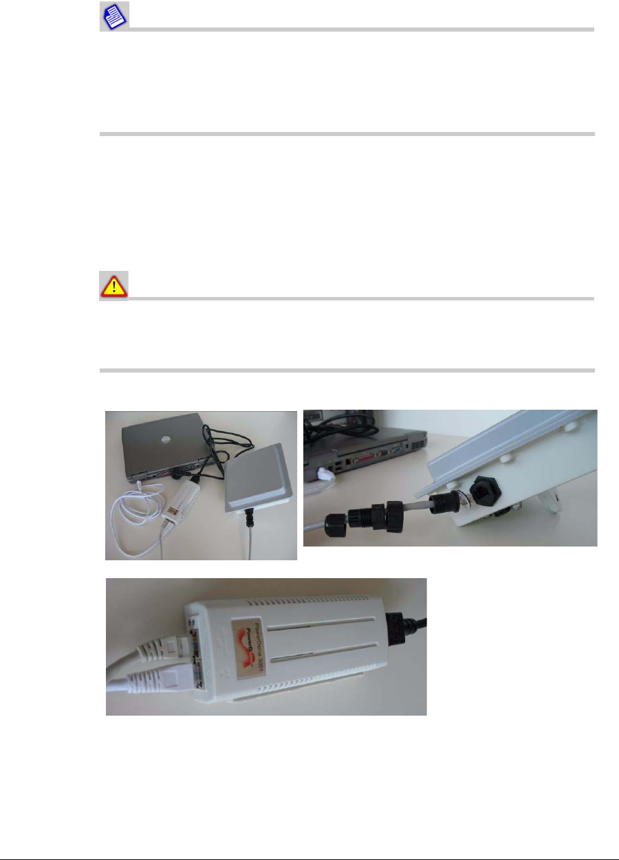
Figure 2-3. Connecting the Equipment
Take care of the proper order of the sealing parts.
POE Injector (POE upper
left cable is data & power
leads to the Subscriber
Station; lower left RF cable
leads to the computer, the
right cable goes to the
electric outlet).
260-668104-001 December 2009 2-5
StarMAX™ 3100 Series Subscriber Station User Manual
When assembling the connector part, it should be ensured that the
gaskets are aligned correctly before tightening the whole assembly and
attaching it to the ODU RJ45 connector to prevent any water ingress
problems.
2-6 Harris Stratex Networks
Chapter 2. Quick Installation of the StarMAX™ 3100 Series Stationary Subscriber Stations
POE Injector/Splitter
The StarMAX™ 3160 Subscriber Station is powered via a POE device, consisting of a
POE Injector and a POE Splitter. The Injector takes 110-240V AC power and converts
it to a DC voltage to transfer it through the CAT5 cable along with data. The Injector is
typically installed in the “wiring closet” near a CPE or Ethernet switch/hub. The POE
Splitter takes the output of the Injector (data + electric current), picks-off the DC
Voltage that has been injected into the Ethernet cable by the Injector and makes it
available to the equipment through the regular DC power jack. The data separated from
the DC voltage is forwarded to the device through a separate data jack. The splitters are
typically installed near the equipment running on a POE supply.
You have to ensure a proper grounding for all installations!
To prevent damage of the equipment it is recommended to use
splitters and injectors of the same make!
The POE should be placed in a cool and dry place. The 110-240V
AC power connector should be connected firmly to the socket!
The grounding point and the POE connector of the Full Outdoor
Subscriber Station have to be oriented downwards to avoid any
water leakage into the unit!
The network (Cat5) cable must have both ends terminated with
properly crimped RJ45 connectors by using one type of the T658A
or T568B wiring standard, tested with the Network (Cat5) tester/
analyzer. The LTW cap must be installed as well. The POE
circuitry at the Subscriber Station might fail or the Ethernet port
might fail as well or it might not work properly. Additionally the
POE injector would detect an error and wouldn't establish any
voltage.
Precaution Guidelines
In order to prevent damage of the equipment please follow the precautions described
below before powering the equipment on.
• Test the Subscriber Station on the ground before installation (connect both cables to
the Ethernet ports by using short Cat5 cables.
• Turn the notebook on.

260-668104-001 December 2009 2-7
StarMAX™ 3100 Series Subscriber Station User Manual
• Connect the 110-240V power voltage to the POE injector (this should be connected
the last. Wait for a few seconds and check whether the green lights from the POE are
coming up: first the power green light next to the POE green light. If the LED is
blinking there is no voltage delivered and something is wrong).
• Verify that the modem is reaching Operational status (that means it is connected to
the Base Station and it can pass the ping traffic); if operational status has been
reached then proceed to the next step. If not then check once more the steps
described above; in case of failure for the second time, send the modem back to the
factory.
• For modems that have reached the Operational status ping and start short traffic
tests to verify the web connectivity.
• For modems that have reached the web connectivity, continue with the field unstable
Cat5 cable testing.
Important! It is essential that the main voltage (110-240V ) is
disconnected before disconnecting any other cable!
• Disconnect the power first!
• Remove the Cat5 cable from the SS-ODU to the POE injector;
• Replace with the Cat5 cable that the Subscriber Station is going to be installed with
(since this cable may be crimped in the field, the Cat5 cable must have both ends
terminated with properly crimped RJ45 connectors by using one type T568A or
T568B wiring standards and tested with Cat5 tester/analyzer; the LTW cap must be
installed as well – see the description in the table below).
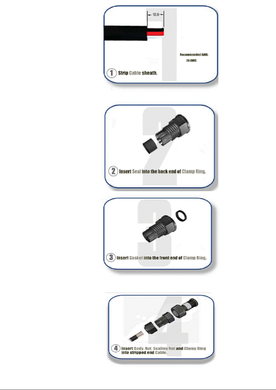
Figure 2-4. LTW Parts
2-8 Harris Stratex Networks
Chapter 2. Quick Installation of the StarMAX™ 3100 Series Stationary Subscriber Stations
Step by step istructions:
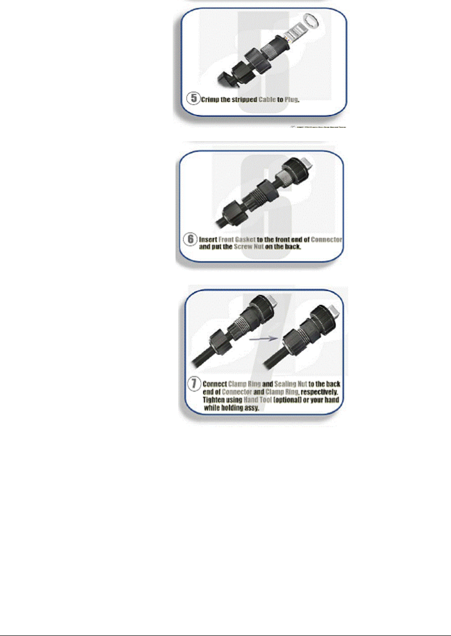
260-668104-001 December 2009 2-9
StarMAX™ 3100 Series Subscriber Station User Manual
2-10 Harris Stratex Networks
Chapter 2. Quick Installation of the StarMAX™ 3100 Series Stationary Subscriber Stations
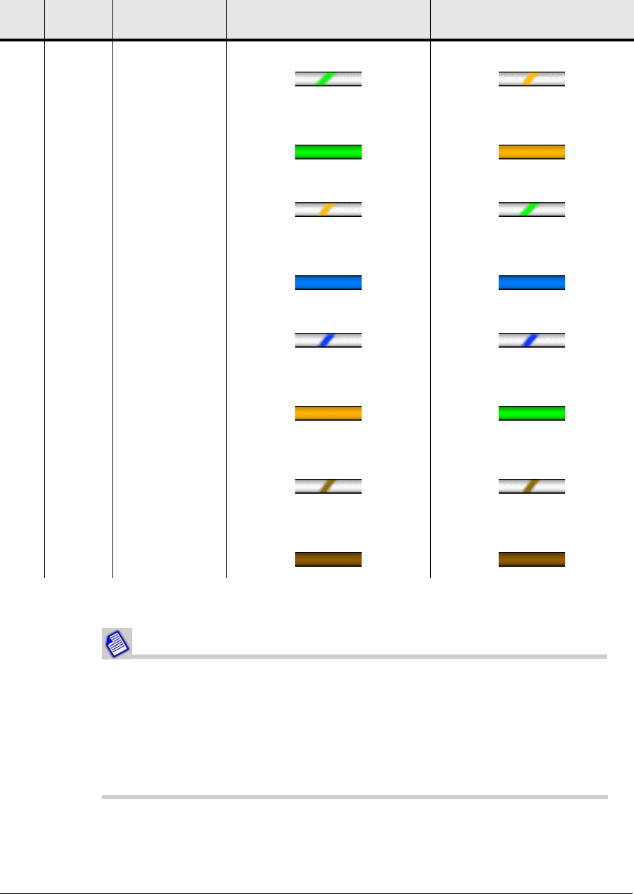
Table 2-1. EIA/TIA 568B connector pinout
It is better that the Cat5 cables are properly prepared and tested before
going into the field!
If the Cat5 cable that is crimped in the field is not properly wired or the
wires are not following one of the T568A or T568B wiring standards, the
POE circuitry at the SS-outdoor unit may fail or the Ethernet port might
fail as well or might not work properly. Additionally, the POE injector will
detect an error and won't establish voltage.
Pin Name Description EIA/TIA 568A cable colors EIA/TIA 568B or AT&T
258A cable colors
1TX+ Tranceive
Data+
White with green stripe White with orange stripe
2TX- Tranceive
Data-
Green with white stripe or
solid green
Orange with white stripe or
solid orange
3 RX+ Receive Data+ White with orange stripe White with green stripe
4 n/c Not connected Blue with white stripe or solid
blue
Blue with white stripe or solid
blue
5 n/c Not connected White with blue stripe White with blue stripe
6 RX- Receive Data- Orange with white stripe or
solid orange
Green with white stripe or
solid green
7 n/c Not connected White with brown strip or
solid brown
White with brown strip or
solid brown
8 n/c Not connected Brown with white stripe or
solid brown
Brown with white stripe or
solid brown
260-668104-001 December 2009 2-11
StarMAX™ 3100 Series Subscriber Station User Manual
Troubleshooting Guidelines
For Subscriber Stations that have already been installed and fail to work properly check
the following:
• Are the POE lights both green? If yes, the POE is working properly; if not disconnect
the 110-240V and reconnect then wait for a few seconds and check that the green
lights are on.
• If no green lights are present, then the POE circuitry is detecting a failure in the Cat5
cabling or the SS-ODU circuitry. Check the Cat5 first for proper connection or
damage. Eventually test with a new Cat5 cable.
• If the green lights are on, test that the modem reaches Operational Status: ping and
make a traffic test. If this is failing, then remove the SS-ODU.
• If one or the other green lights is not on, then replace the POE injector and repeat the
procedure to check for green lights, operation, ping, traffic; if OK, then the POE
injector is failing.
• If still failing with the new POE injector, then remove the SS-ODU, the original Cat5
cable, and the original POE injector; pack them all and ship all of the items
TOGETHER for failure analysis to RMA and describe the failure.
Sealing the StarMAX™ 3160 POE Injector
The sealing on the bottom side of the Subscriber Station should be closed tightly to
prevent any water leakage into the unit. For details see Figure 2-3.
The StarMAX™ 3160 Subscriber Station has a built-in panel antenna. Use
the 4-LED display to see the measured signal strength in order to place
the unit in the optimal position.

2-12 Harris Stratex Networks
Chapter 2. Quick Installation of the StarMAX™ 3100 Series Stationary Subscriber Stations
260-668104-001 December 2009 3-1
Chapter 3. Antenna Alignment
Using wireless data communications involves signal transmission and reception in
various environments, where building configurations can sometimes interfere with the
transmitted signals. Therefore you have to optimize the placement and the direction of
the StarMAX™ Subscriber Station and/or its optional external antenna.
It is advisable that you try to find the optimal location for placing the Subscriber Station
and/or the antenna prior to fixing the Subscriber Station and/or antenna to any fixed
objects, such as poles or walls (installations described in Chapter 2).
To do this you can use the built-in SS HTML GUI, described in Chapter 6 of this
manual. Under the Antenna Graph option you can read out the CINR and RSSI values
and you can read out the signal quality and strength parameters. RSSI and CINR
thresholds are specified as RSSI/CINR @ 3MHz: - 84dB/12dB; RSSI/CINR @ 6MHz:
- 82dB/12dB. CINR values lower than 12 dB should not be acceptable.
For professional installations a specialized Alignment Tool application can be used to
evaluate the receive signal strength values (RSSI) and to adjust the Subscriber Station
accordingly.
If using the SS HTML GUI to find the optimal space for positioning the SS,
please refresh the Antenna Graph every time you reposition the
equipment.
When finding the optimal position for your outdoor antennas please follow these
guidelines:
• Ensure that the outdoor unit of the antenna provides direct line of sight (LOS) or
near line of sight (NrLOS) conditions to the Base Station antenna.
• In the no line of sight (NLOS) conditions direct the antenna to the open space and
not directly towards the nearest obstructions such as tall buildings, hills, trees etc.
• To achieve a better link quality, place the Subscriber Station antenna as high as
possible.
• Ensure that the location of the antenna is easily accessible for a safe installation and
testing.
• When deciding about the location of the Subscriber Station, take into account the
location of the power outlet and of your data equipment.
To make a fine antenna alignment in the horizontal direction (left-right) or in the
vertical direction (up-down), you should slightly loosen the corresponding nut to
enable the movement of the antenna in the desired direction.
3-2 Harris Stratex Networks
Chapter 3. Antenna Alignment
When precise positioning is required (with the Outdoor units), there is
also an optional Alignment Tool available, which enables optimal location
search. More information on obtaining the Alignment Tool is available at
the Harris Stratex Networks Customer Support site -
www.support.harrisstratex.com.
260-668104-001 December 2009 4-1
Chapter 4. Subscriber
Commissioning
This section covers the following topics:
•Required Information
•Configuring Basic Parameters
•Aligning the Subscriber Unit Antenna
•Operational Verification of the Subscriber Station
Required Information
Tabl e 4-1 lists the parameters required for bringing the Subscriber Station to the
minimal operational state.
Table 4-1. Information needed to get Subscriber Station operational
Configuring Basic Parameters
During the Subscriber Station power-up, the following stages occur before the
Subscriber Station is synchronized with the Base Station:
1. Complete Power On Self Test.
2. The Subscriber Station scans the configured connection channel and synchronizes
with the Base Station with the best RSSI or CINR values. To configure new
channels, refer to Subscriber Station HTML GUI on page 6-1.
Item Parameters What should be updated
Management Port
(mandatory)
IP Address 192.168.1.1
Subnet Mask 255.255.255.0
RF Interface
(mandatory)
Frequency (in kHz) Sample 2500000, 2585000
Bandwidth (in kHz) 10000
4-2 Harris Stratex Networks
Chapter 4. Subscriber Commissioning
Aligning the Subscriber Unit Antenna
This section is applicable only to the Outdoor Subscriber Station.
The link quality measurement can be obtained using the web based SS HTML GUI
management interface (see Subscriber Station HTML GUI on page 6-1 for
details). The Signal LED on the Subscriber Station flashes when the registration
process is in progress and is on when the Subscriber Station is registered.
To align the outdoor antenna, please follow these steps:
1. Point the antenna towards the general direction of the base station.
2. Verify that the power LED of the Subscriber Station is on.
3. Check the signal LED- flashing indicates that the Subscriber Station is
synchronized with the Base Station. If the signal LED is off, check the basic
configuration of the Subscriber Station.
4. Check whether the Signal LED is on after flashing green for few seconds. If the
signal LED continues to flash, try to change the direction of the antenna or position
the antenna at a higher or an alternate location.
5. Use the SS HTML GUI to ascertain the best link quality (see Subscriber Station
HTML GUI on page 6-1 for details).
Verifying Data connectivity
To verify data connectivity, try to connect to the Internet from the end-user's PC (see
Configuring Your Computer (MS Windows) on page 5-1 for details).

260-668104-001 December 2009 5-1
Chapter 5. Configuring Your
Computer (MS Windows)
This chapter describes how to configure computers for the StarMAX™ 3100 Series
Subscriber Station. Topics include:
•Setting the IP Address on page 5-1
•Verifying the Connection on page 5-3
•Setting the Password on page 5-5
Setting the IP Address
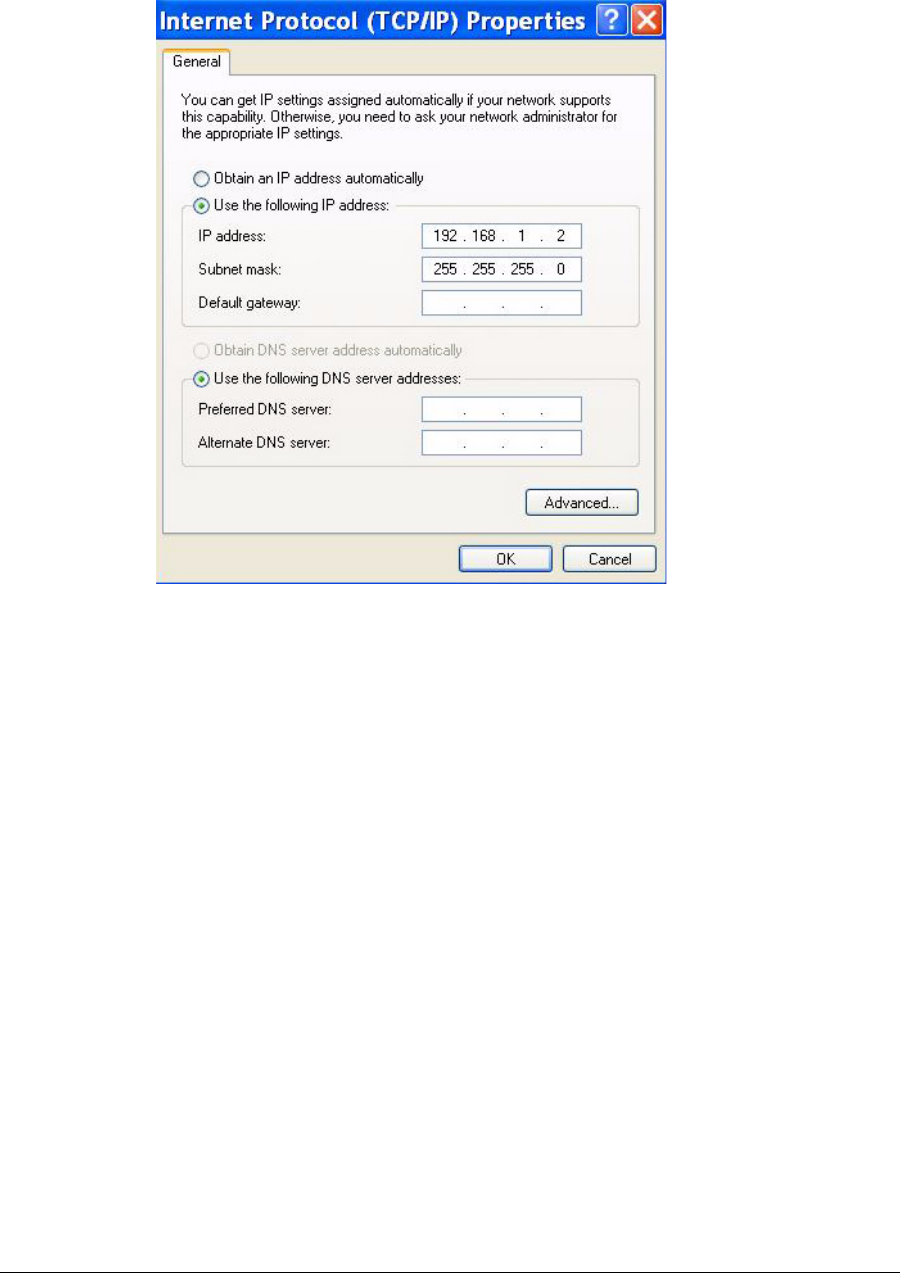
The quickest way to start using the correctly installed StarMAX™ 3100 Series
Subscriber Station is to configure your computer network port for a fixed IP address
that is in the same subnet as the default IP address of the Subscriber Station which is
192.168.1.1. The computer’s IP address should be in the range 192.168.1.2. through
192.168.1.254. Follow these steps to configure a computer for a static IP:
1. Click on Start > Settings > Control Panel.
2. Double click Network Connections.
3. Find the LAN connection that is connected to the Subscriber Station, right-click the
connection and check the Status. It should be connected.
4. Then right-click on the Properties/General tab and select Internet Protocol
(TCP/IP) and click Properties.
5. As shown in Figure 5-1, select the following options:
a. Use the following IP address
b. Subnet mask
5-2 Harris Stratex Networks
Chapter 5. Configuring Your Computer (MS Windows)
Figure 5-1. Fixed IP address
After the IP address of the computer has been set you can configure the scanning
conditions by the web based application described in Subscriber Station HTML GUI
on page 6-1 and start scanning for the best signal. The Subscriber Station is usually
able to connect to the Base Station of the network in a couple of minutes (it usually
takes about 0.5-2 minutes, which depends on the configuration of the Subscriber
Station) after the Subscriber Station has been powered on. Once the Subscriber Station
is operational (as shown in Subscriber Station HTML GUI on page 6-1), you
should configure your computer in accordance with the settings of the operator (DHCP,
PPPoE or static IP). Please follow the instructions given by the operator.
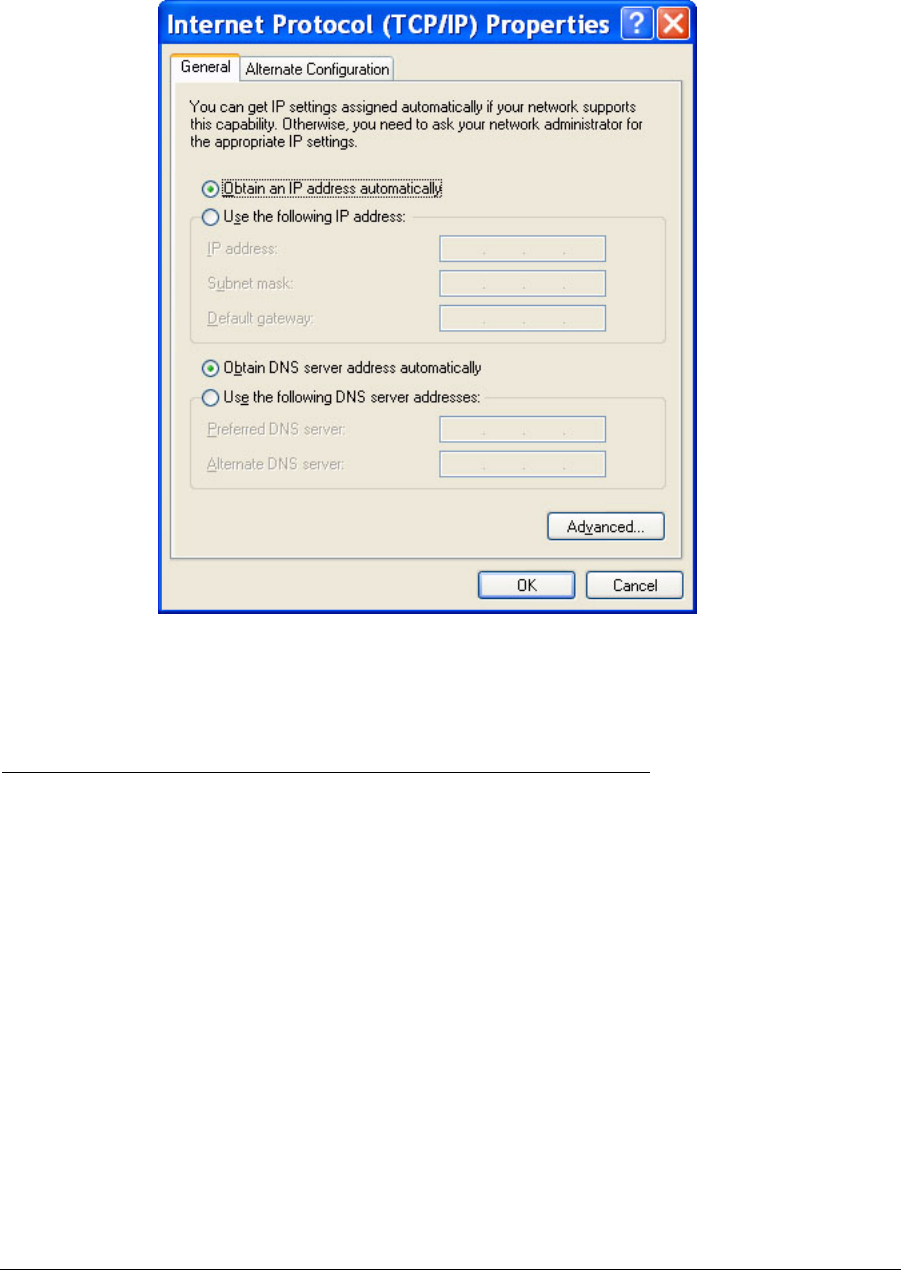
The following example shows the case of dynamic IP address assignment.
1. Click on Start > Settings > Control Panel.
2. Double click Network Connections.
3. Find the LAN connection that is connected to the Subscriber Station, right-click the
connection and select Properties.
4. In the General tab, select Internet Protocol (TCP/IP) and click Properties.
5. As shown in Figure 5-2, select the following options:
a. Obtain IP address automatically
b. Obtain DNS server address automatically
260-668104-001 December 2009 5-3
StarMAX™ 3100 Series Subscriber Station User Manual
Figure 5-2. Automatic IP assignment
Verifying the Connection
To check whether the PC is connected to the WiMAX network, check the status of the
LAN interface which is connected to the Subscriber Station.
Dynamic IP address and 1:N NAT
1. Click on Start > Settings > Control Panel.
2. Double click Network Connections.
3. Find the LAN connection that is connected to the Subscriber Station.
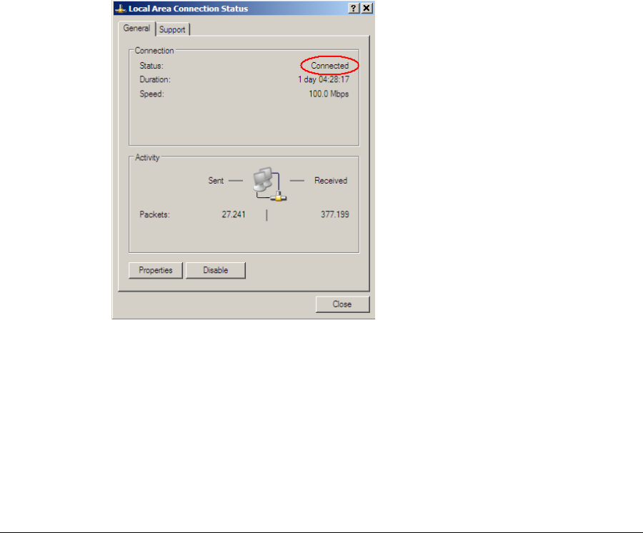
4. Right-click the connection and select Status; it should be Connected.
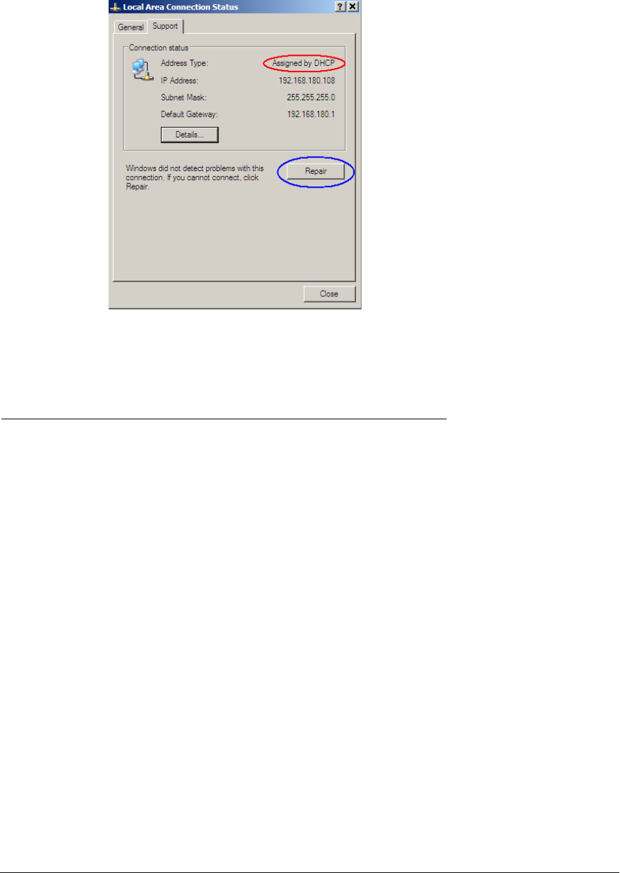
5. In the same window select the Support tab; it should be Assigned by DHCP.
If another status is observed, then right-click the connection and select the Repair
option. Perform the upper check if any change. Check the cabling.
5-4 Harris Stratex Networks
Chapter 5. Configuring Your Computer (MS Windows)
Static IP address and N:N NAT
To check whether the PC is connected to the WiMAX network, check the status of the
LAN interface which is connected to the Subscriber Station.
1. Click on Start > Settings > Control Panel.
2. Double click Network Connections.
3. Find the LAN connection that is connected to the Subscriber Station.
4. Right-click the connection and select Status; it should be Connected.
5. In the same window select the Support tab; it should be Manually Configured.
6. Use the Details button to check if the IP settings are the same as given by the
operator.
If another status is observed, check the cabling; if wrong IP settings are defined, change
the IP settings under the TCP/IP settings.
PPPoE
Check the documentation given by the Operator. In most cases the physical state of the
interface will be as mentioned above (1 or 2) with additional Dial-Up connection
defined in the Network Connections window.
Figure 5-3. Connection Status
260-668104-001 December 2009 5-5
StarMAX™ 3100 Series Subscriber Station User Manual
Figure 5-4. Support Tab
Setting the Password
You can login to a Subscriber Station by using the telnet and the IP address of the
Subscriber Station.
Example: telnet 192.168.185.61
A login and password dialog appears. There are different privileges with respect to
the user logged in. A password can also be set when logged on the Subscriber Station.
The support password logic has been changed to provide better security for the
Subscriber Station. There are several options to login to the Subscriber Station.
• For users with limited access you can use the following combination:
Login: root
Password: telsimawl
• For advanced users dynamic password logic has been created:
•If the startupconfig is not present in the SS (modem), the default password for the
Login: support is starmax<SS>TS<D><HH> where
<SS> is the last two digits of the box’s serial # (if the FRU is not in the Subscriber
Station, then the serial number will be “TW”)
TS are just letters that stand for Telsima
<D> is the first letter of the day of the week
<HH> is the two digit hour in military time

5-6 Harris Stratex Networks
Chapter 5. Configuring Your Computer (MS Windows)
•If the startupconfig is present in the Subscriber Station (modem) and no user
has modified the support user password (default generated for the
startupconfig), the password in the startupconfig for the Login: support is
support<SS>TS<D><HH>.
•If the startupconfig has got any other password set for the user: support, then
the password for the user: support will be that. If the password is Telsima, then
the password would be: telsima<SS>TS<D><HH>.
The following logic has been applied for the default/user changed password for support
user:
Example: starmaxTWTSW05
<actual password> <SS>TS<D><HH>
<actual password> is the current support password starmax
To assist the user to arrive to the <SS> serial number, <D> day of the week and <HH>
hour, the telnet logic for the Subscriber Station has been modified as below:
System Time and Date: THU DEC 27 00:00:20 1990
Serial Number: Z00000000
Login:
Password:
Telsima_ss#
Telsima_ss#

260-668104-001 December 2009 6-1
Chapter 6. Subscriber Station
HTML GUI
The Subscriber Station HTML GUI is a web based application, designed for
management of the StarMAX™ Subscriber Stations and for monitoring the incoming
RF signal levels (RSSI, CINR). HTTP servers basically provide access to monitoring
and configuration of the device. The HTTP server is supported by both the Base
Stations and the Subscriber Stations. The Subscriber Station HTTP server supports
HTML pages mainly for configuration and monitoring of various aspects of the
Subscriber Station. The following functionalities can be configured and/or monitored
at the Subscriber Station:
• IP address related configuration
• Downlink radio measurement information
• Scanner channel configuration
• Miscellaneous configuration, such as Subscriber Station reset etc.
• Network Address Translation information and configuration
• IP and MAC filtering information and configuration
The HTTP server in the Subscriber Station consists of standalone modules that are
primarily used for enabling the JAVA Web Start technology. They access the JAVA Web
Start files present in the system, and send them back to the HTTP Client when they are
requested.
The HTTP Server in the Subscriber Station is serving traditional HTML pages to the
web browser, and is used for configuring and monitoring the system.
Ethernet Link Down
During the Subscriber Station power-up process the Ethernet link can be enabled or
disabled by default, thus enabling/disabling the user of the station to access the
Subscriber Station while the station is in the RF offline mode. The administrators can
modify the behavior of the Ethernet link when the Subscriber Station goes from
non-operational state to the operational state and vice-versa on the RF link.
By default, this feature is disabled to provide Ethernet access to the Subscriber Station
for configuration and management reasons.
This feature is active only when the Ethernet link is configured for power down mode.
The Subscriber Station will bring up the Ethernet interface and the link will be active
during the power cycle. The Ethernet will not be in power down mode by default.
The power down mode can be enabled or disabled (see the StarMAX™ 3100 Series
Subscriber Station Support Manual for details).
6-2 Harris Stratex Networks
Chapter 6. Subscriber Station HTML GUI
HTML GUI Introduction
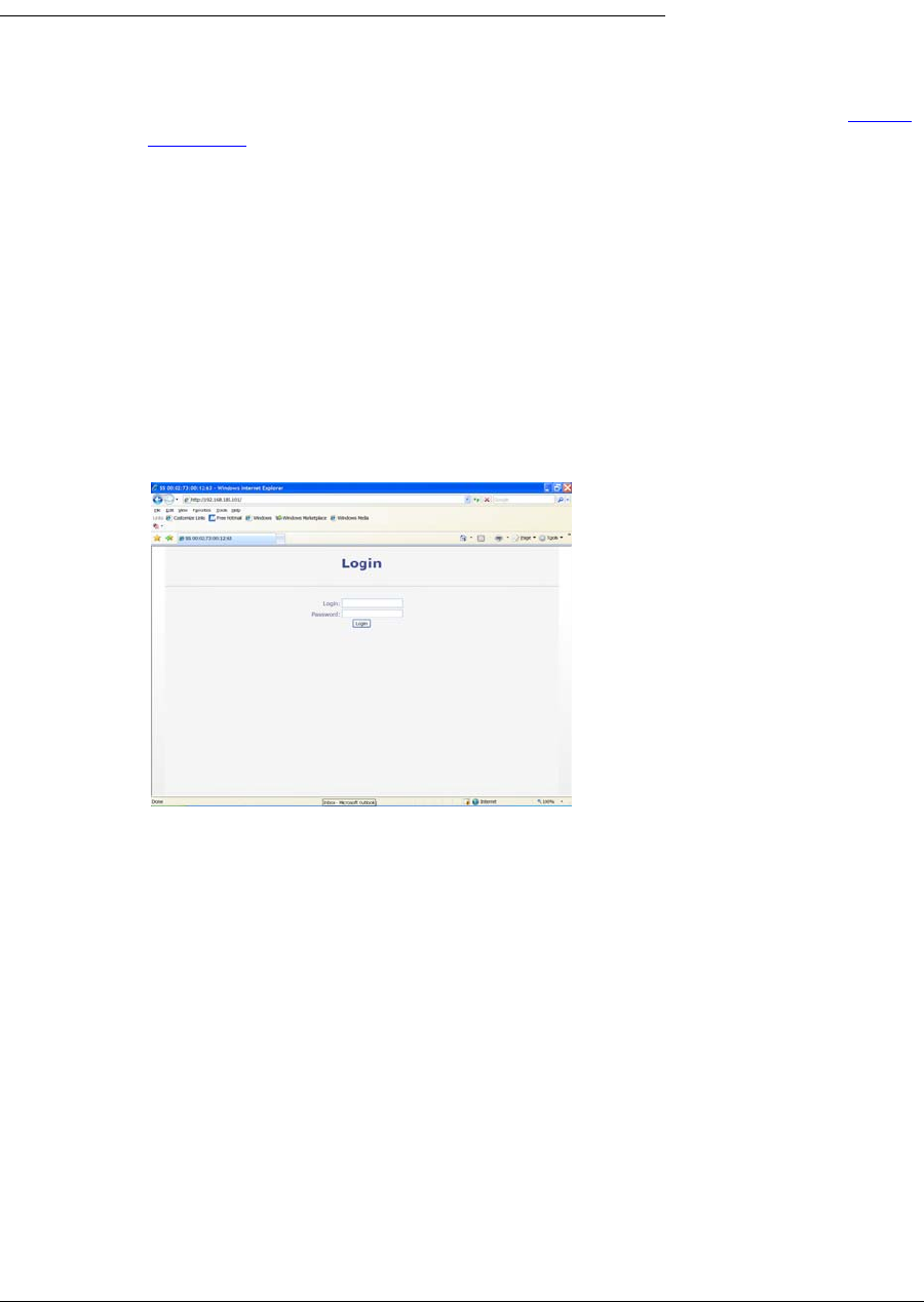
The Subscriber Station HTML GUI is accessed through the web browser at the default
address of the Subscriber Station. The user/administrator needs to open the web
browser and type in the Subscriber Station’s default IP address (default IP is: http://
192.168.1.1); then the username and password need to be provided to access the
configuration and management options of the StarMAX™ 3100 Series Subscriber
Station through the Subscriber Station HTML GUI.
Authentication (Login/Password)
The authentication tab is used to accept the HTML client user name and password and
validate further access to the user for the Subscriber Station configuration. The default
username/password pair for an ordinary user is admin/admin. The administrator’s
username/password will be delivered by the operator for security reasons. The
administrator has more privileges then an ordinary user. This manual is intended for
both kinds of users, so some screenshots presented in the manual can be seen only by
an administrator who has full privileges.
Figure 6-1. Login to the Subscriber Station HTML GUI
System Info Tab
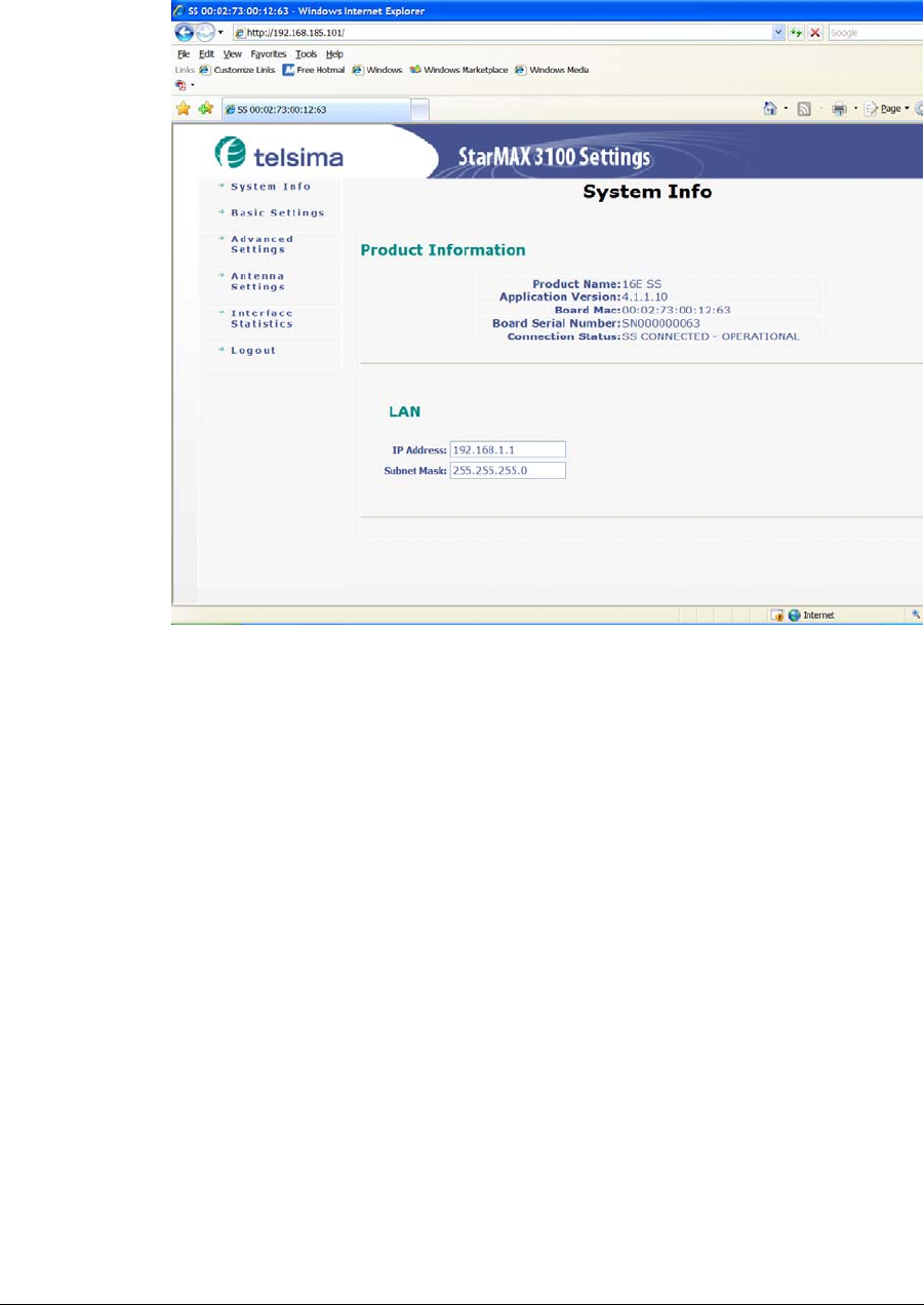
The System Info tab contains the key information about the Subscriber Station
including the Ethernet connection, the IP Address of the Subscriber Station, the Subnet
mask, the WiMAX acquired IP Address, Gateway and Subnet IP. The Ethernet Power
down mode can be enabled/disabled in this tab (see Ethernet Link Down on
page 6-1 for a description). The current Running Configuration can be shown in this
tab as well as the application version, MAC address of the board and serial number of
the board. An administrator can modify the Ethernet IP address whereas the WiMAX
IP address is read only.
260-668104-001 December 2009 6-3
StarMAX™ 3100 Series Subscriber Station User Manual
Figure 6-2. The System Info tab
6-4 Harris Stratex Networks
Chapter 6. Subscriber Station HTML GUI
Basic Settings
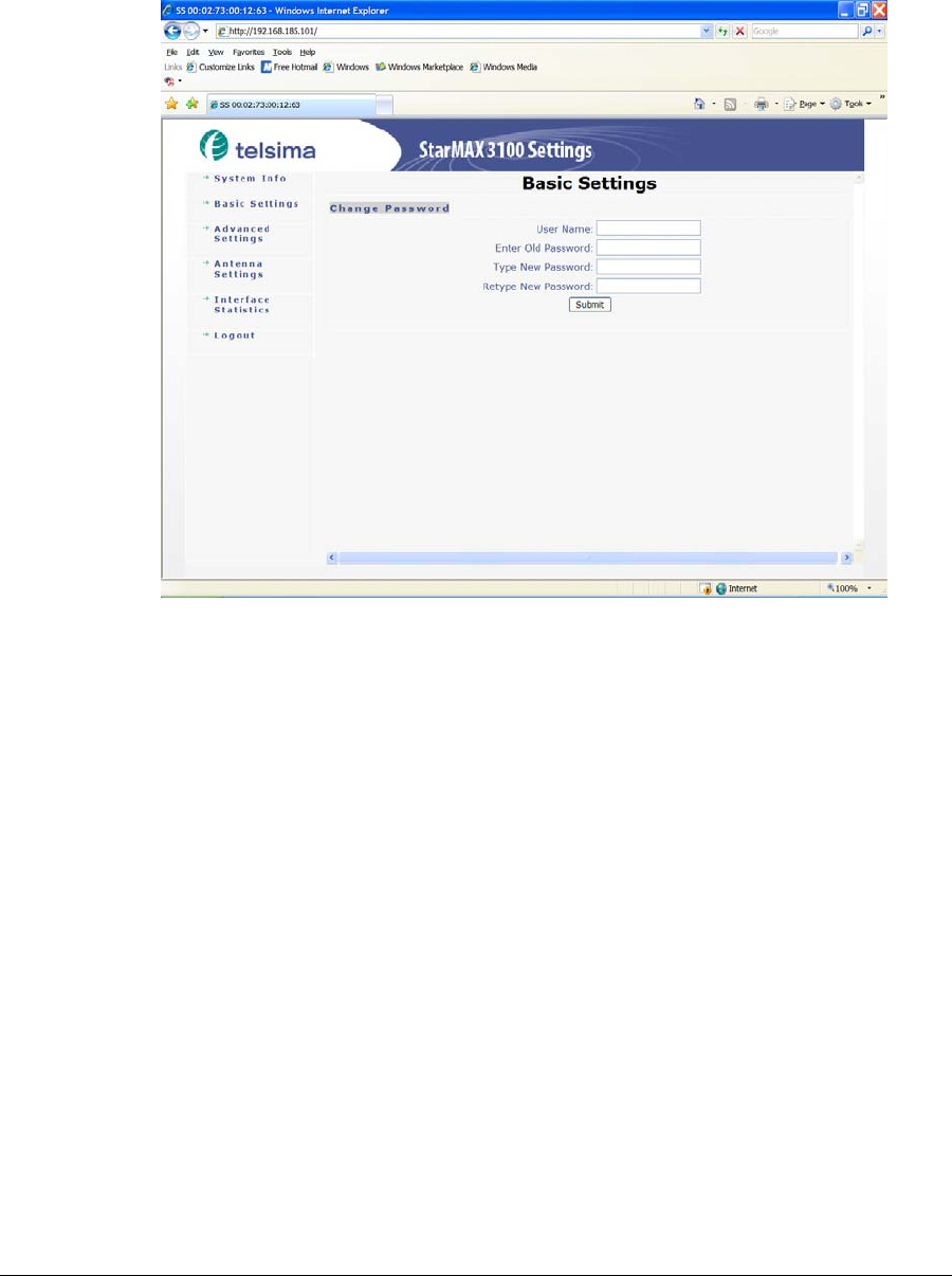
In this tab the password can be changed for a different user name.
Figure 6-3. The Basic Settings tab
Advanced Settings Tab
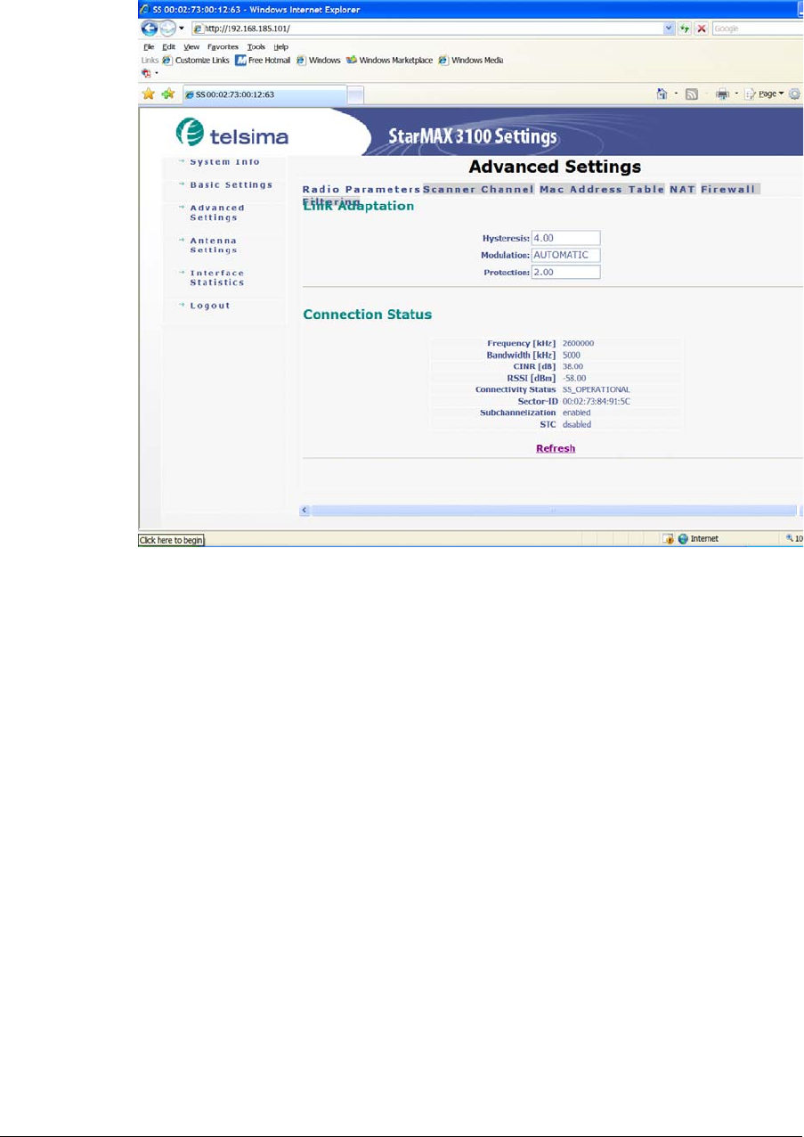
The Advanced Setting tab displays the following sub-tabs: Radio Parameters, Scanner
Channel, Mac Address Table, NAT and Firewall Filtering. The Radio Parameters
sub-tab displays information on the radio connection status and working attributes.
The Subscriber Station administrator can set values for Hystersis, Modulation and
Protection and see the active Connection status – the Frequency, Bandwidth, CINR,
RSSI, Connectivity Status, Sector-ID, Subchannelization and STC values.
260-668104-001 December 2009 6-5
StarMAX™ 3100 Series Subscriber Station User Manual
Figure 6-4. Radio Parameters sub-tab
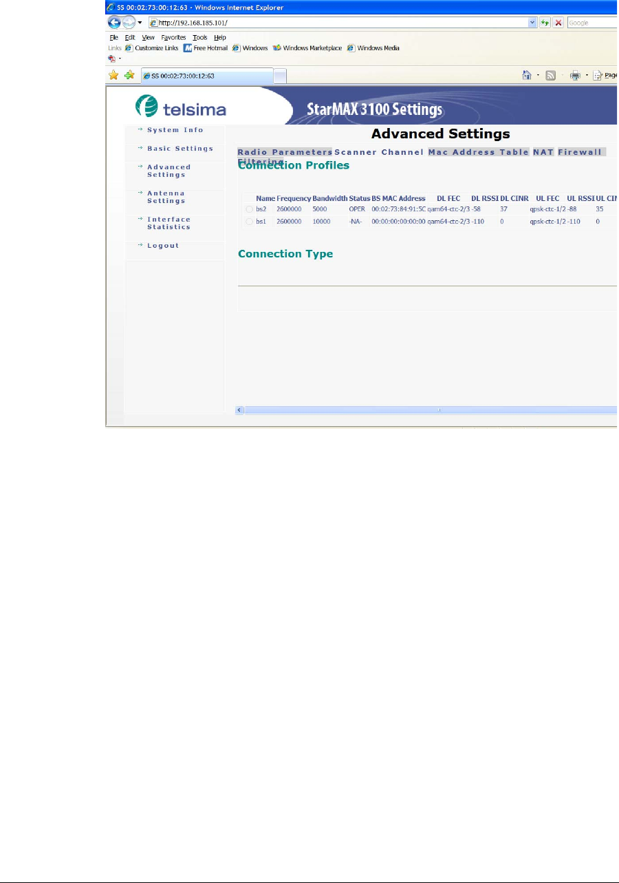
In the Scanner Channel sub-tab scanner information can be added or removed by
clicking on the Add-Scanner or Remove-Scanner button (first selecting the
Scanner to be removed). This tab also enables connecting, disconnecting and
re-synchronizing of the connection and setting it to the automatic or manual
connection. All these options as permitted only to an administrator.
6-6 Harris Stratex Networks
Chapter 6. Subscriber Station HTML GUI
Figure 6-5. Scanner channel sub-tab
The Mac Address Table sub-tab enables listing of the Subscriber Station from the
MAC address table (Dynamic entries and Static entries) (press the clearMAC
Address Table button to clear the table) or adding a new MAC Address (addMAC
button) to give the network administrator a better overview of the connected users.
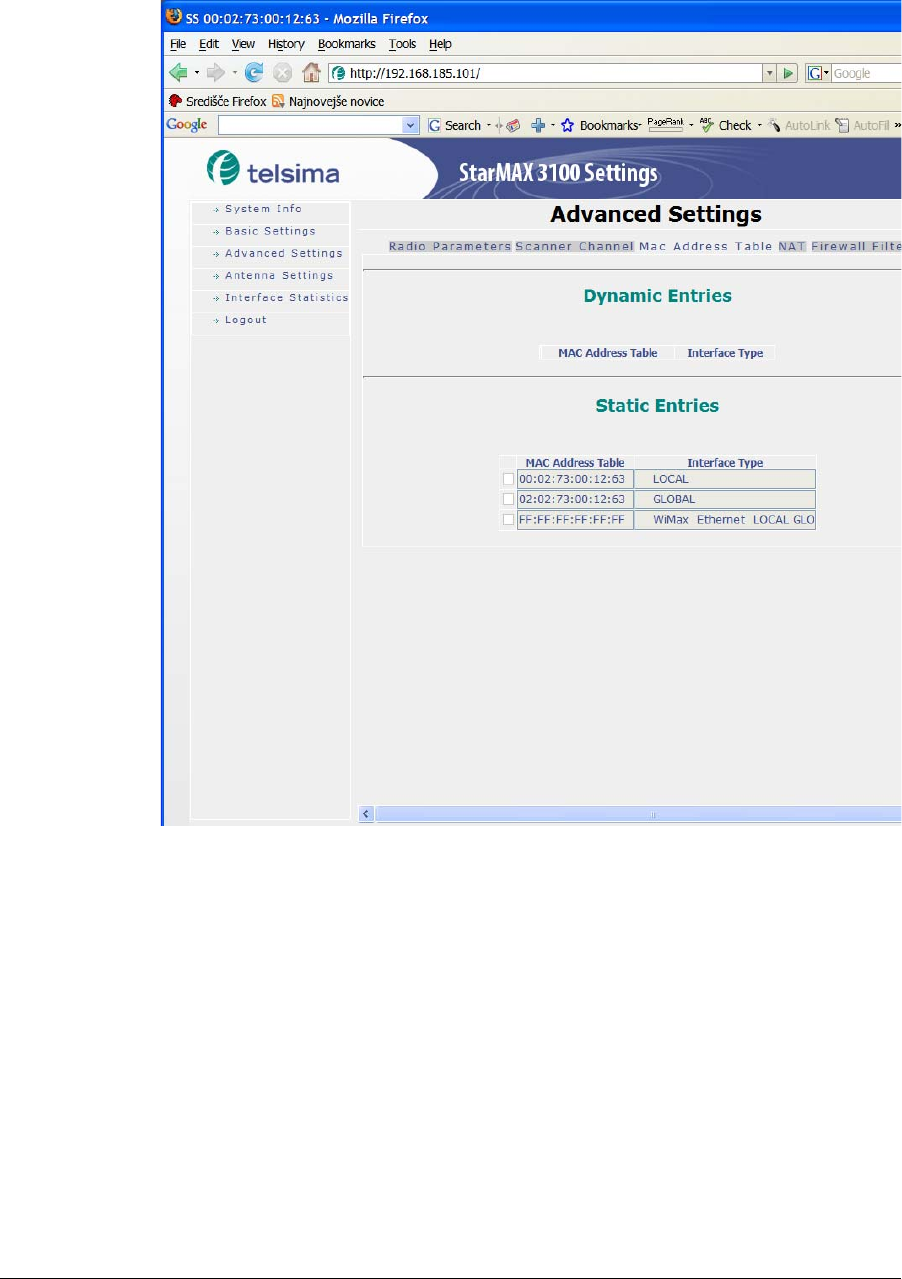
260-668104-001 December 2009 6-7
StarMAX™ 3100 Series Subscriber Station User Manual
Figure 6-6. MAC Address Table sub-tab
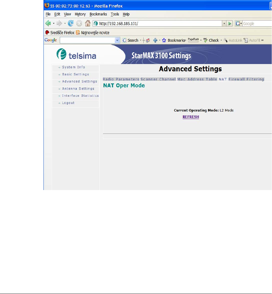
The NAT sub-tab shows the current operation mode. The Network Address
Translation (NAT, also known as Network Masquerading, Native Address Translation
or IP Masquerading) method enables the Subscriber Station to act as a traditional layer
3 NAT device, possibly in conjunction with an external or an internal Ethernet switch.
With NAT enabled the Subscriber Station will not forward the VLAN tagged packets.
Tagged packets received at any interface will be dropped by the Subscriber Station,
thus allowing greater security of the network users and the network itself. MVLAN and
VoIP classifications are not supported in the NAT mode. (see the Network Address
Translation (NAT) on page 7-1 for details).
NAT N:N related parameter configurations – Primarily the N:N entry has to be added
with a local IP address and local subnet mask, global IP address and global subnet
mask, and gateway before setting the NAT operation mode to N:N.
6-8 Harris Stratex Networks
Chapter 6. Subscriber Station HTML GUI
NAT 1: N Global IP address set to Static IP scenario – DHCP server configuration with
Base and End IP address and DHCP lease time are necessary. The Global IP address,
Global IP address subnet mask, Global IP gateway address and Global IP DNS address
are required before configuring the 1:N NAT mode. The 1:N entry is dynamically
configured by the NAT module. If DMZ (see Chapter 7) is enabled then the DMZ IP
address must be configured. These are the configurations provided from the Subscriber
Station HTML GUI for the 1:N NAT scenario.
NAT 1:N Global IP address set to the DHCP scenario – DHCP server configuration with
a Base and End IP address and DHCP lease time are required before configuring the 1:
N NAT mode. If DMZ is enabled then the DMZ IP address must be configured. These
are the configurations provided from the Subscriber Station HTML GUI for the 1:N
NAT scenario.
Figure 6-7. Nat Oper Mode
260-668104-001 December 2009 6-9
StarMAX™ 3100 Series Subscriber Station User Manual
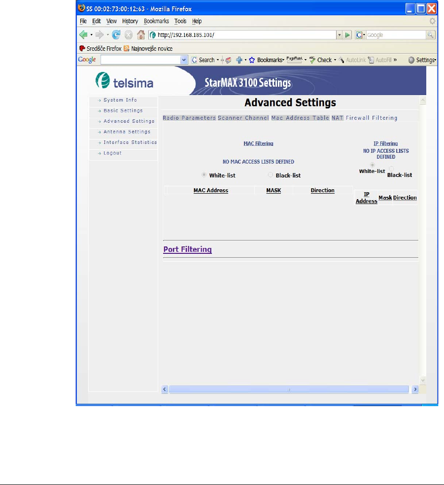
The Firewall Filtering sub-tab enables the administrator to set the firewall
protection and traffic filtering settings. The white-list can include explicitly allowed
MAC Addresses or obtained IP addresses of the network interfaces and the black-list is
used to exclude the network interfaces from the network. MAC/IP addresses can be
filtered in both ways or separately as a source or destination or both (Src, Dest, Both).
IP Filters – Maximum of 16 IP firewall filter entries can be added from the Subscriber
Station HTML GUI specifying the IP address, IP subnet mask and the direction of the
firewall filtering (Ingress or Egress).
MAC filters – Maximum of 16 MAC firewall filter entries can be added from the
Subscriber station HTML GUI specifying the MAC address, MAC netmask and the
direction of the MAC firewall filters (Ingress or Egress).
Figure 6-8. Firewall Filtering sub-tab
6-10 Harris Stratex Networks
Chapter 6. Subscriber Station HTML GUI
Antenna Status Tab
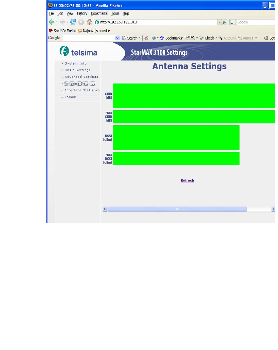
This tab shows the actual antenna transmission/reception signal parameters. The
CINR, MAX CINR, RSSI and MAX RSSI graphs can be seen. The image is not
dynamically updated – to update the new value (when repositioning the unit/antenna
for optimal reception, for example) press the Refresh button.
Figure 6-9. The Antenna reception signal quality status
260-668104-001 December 2009 6-11
StarMAX™ 3100 Series Subscriber Station User Manual
Interface Statistics Tab
This tab enables viewing the counters for Subscriber Station WiMAX and Subscriber
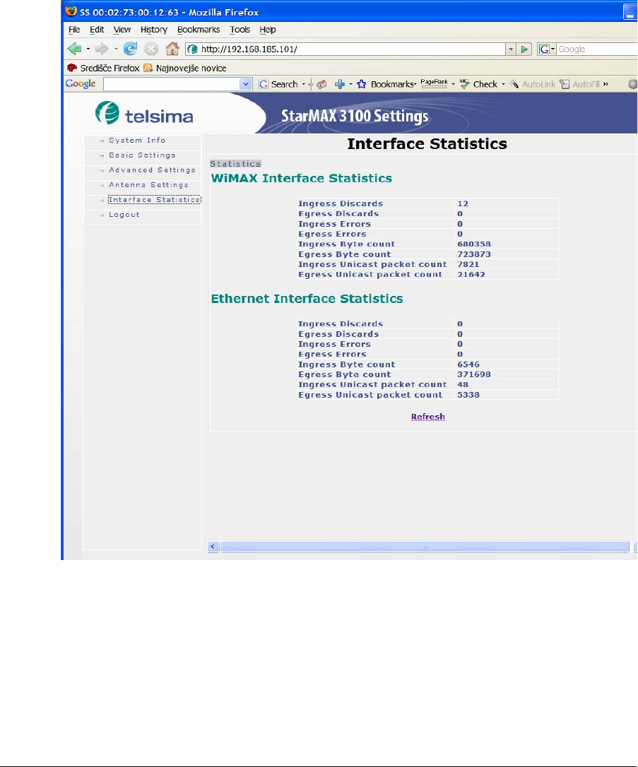
Station Ethernet Interfaces. The following counters are displayed: InOctets, OutOctets,
InUCastPkts, OutUCastPkts, InDiscards, OutDiscards, InErrors and OutErrors for
WiMAX and Ethernet interfaces respectively. All these counters show real-time values
when refresh is clicked or the first time the page is open, except the WiMax OutErrors.
The WiMax OutErrors displays the last 15 minutes total count.
Figure 6-10. Interface Statistics
6-12 Harris Stratex Networks
Chapter 6. Subscriber Station HTML GUI
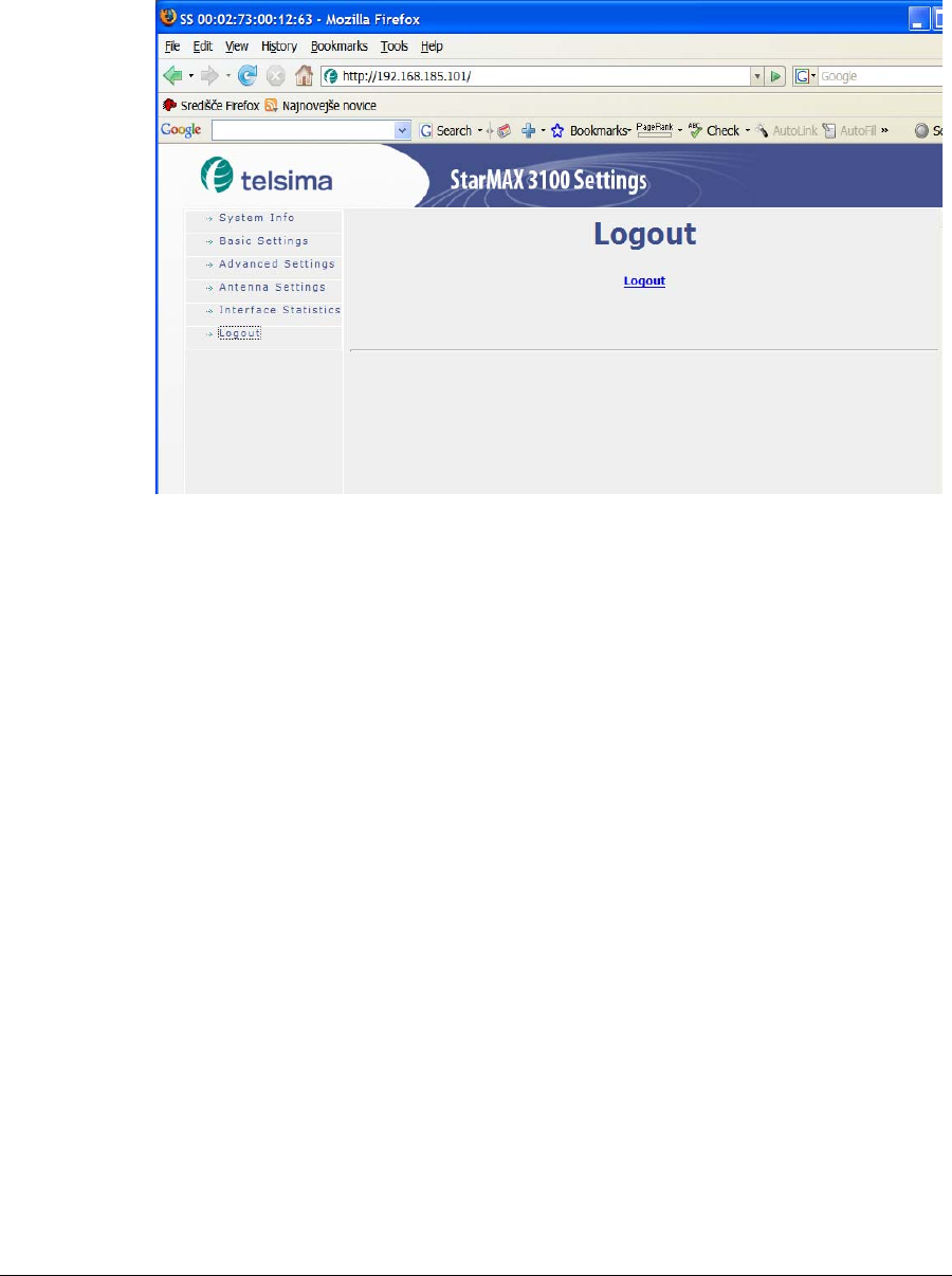
Logout Tab
This tab enables to logout from the HTML GUI.
Figure 6-11. Logout tab
260-668104-001 December 2009 7-1
Chapter 7. Network Address
Translation (NAT)
The Network Address Translation (NAT, also known as Network Masquerading, Native
Address Translation or IP Masquerading) method enables the Subscriber Station to act
as a traditional layer 3 NAT device, possibly in conjunction with an external or internal
Ethernet switch. With NAT enabled the Subscriber Station will not forward VLAN
tagged packets. Tagged packets received at any interface will be dropped by the
Subscriber Station, thus allowing greater security of the network users and the network
itself. MVLAN and VOIP classifications are not supported in NAT mode.
The various VLAN features do not interact with the L3 forwarding of the NAT module
otherwise.
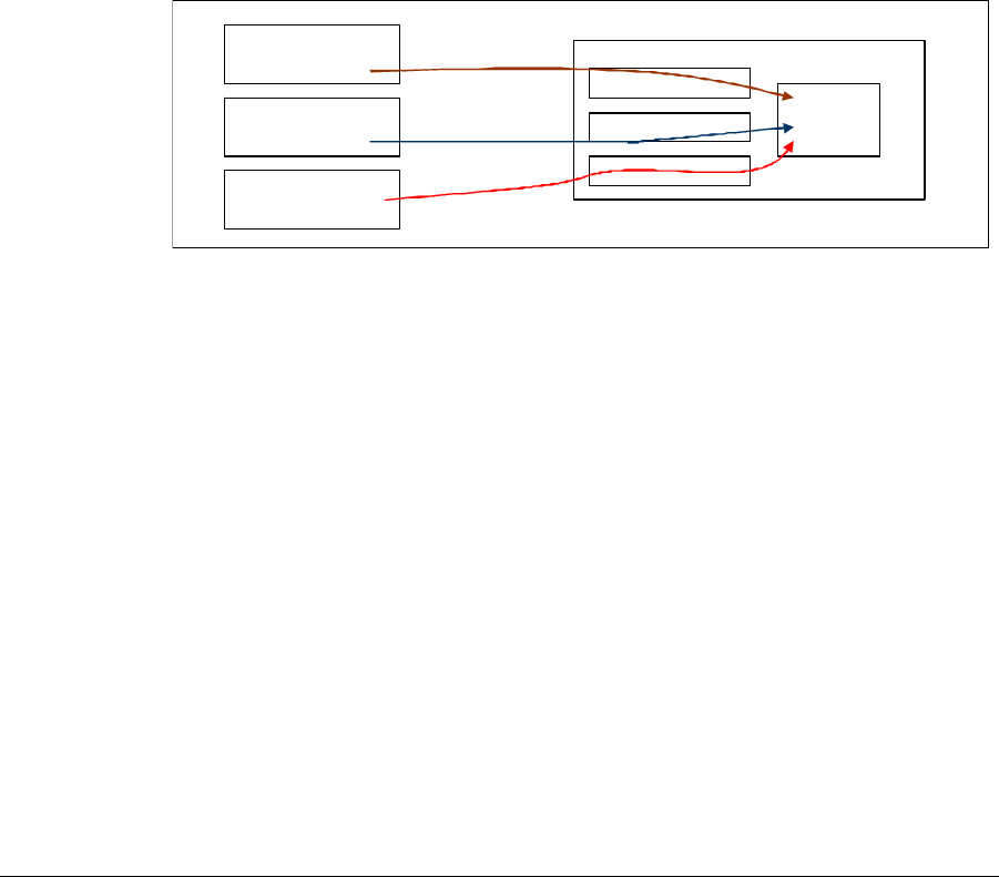
The Subscriber Station NAT module can be configured through the following modules:
• Command Line interface
• Subscriber Station HTML GUI
• SNMP agent for communication with remote NMS servers
Figure 7-1. NAT management options
This chapter includes the following topics:
• Enabling NAT on page 7-2
• Operating Modes (L2, 1:N, N:N) on page 7-2
• Operating Mode Switching on page 7-3
• Provisioning Server Changes on page 7-4
• Interfaces and IP Address Assignment on page 7-4
• N:N NAT Translations on page 7-4
• DHCP Server Configuration on page 7-5
• Access Control on page 7-5
• DMZ on page 7-6
• VLAN traffic on page 7-6
Command Line
Interface
Subscriber Station
HTML GUI
Remote NMS/PS
server
Subscriber Station
C
LI h
a
n
d
l
e
r
s
SS
HTML
Server
SNMP Agen
t
NAT
Managed
Object
7-2 Harris Stratex Networks
Chapter 7. Network Address Translation (NAT)
Enabling NAT
If the Subscriber Station is configured for NAT operation, then once the public IP
address mode has been configured (DHCP or static) the NAT module is initialized.
Operating Modes (L2, 1:N, N:N)
The Provisioning Server configures the Subscriber Station for its network operating
mode: L2, 1:N NAT, or N:N NAT. The Subscriber Station must first obtain its
management IP address; this is assigned via DHCP unless you manually configure a
static IP address, network mask and gateway IP address for the station.
After the management IP has been established, the Provisioning Server configures the
network operating mode. Note that the Subscriber Station will operate in L2 mode until
this configuration is received (the provisioning server cannot configure the Subscriber
Station until after the management IP has been established).
L2 Mode
The L2 Mode is the default mode of operation. This is the mode currently supported in
the Subscriber Station.
1:N NAT
In 1:N NAT mode (also referred to as NAPT - Network Address and Port Translation),
the Provisioning Server will also configure the global IP allocation mode, one of DHCP
or static. In the case of static addressing, the Provisioning Server will also configure the
global IP address, network mask and gateway IP address.
PPPoE is not supported for global IP in this release.
N:N NAT
In N:N NAT mode, the Provisioning Server will configure a set of address translation
pairs (local IP, global IP): the global network mask and gateway IP, and the local IP
address and local network mask.
260-668104-001 December 2009 7-3
StarMAX™ 3100 Series Subscriber Station User Manual
The Subscriber Station’s local IP address will be the gateway for the
network side PCs. All local IP addresses must belong to the network
defined by the local IP address and network mask. All global IP addresses
must belong to the same network defined by the gateway IP address and
global network mask.
Operating Mode Switching
The StarMAX™ supports switching of operating modes between L2 or 1:N or N:N. The
Subscriber Station comes up by default in the L2 mode and then, during the
initialization process, switches from L2 to NAT mode. The other mode changes (NAT
to L2, or 1:N to N:N) require a reboot of the Subscriber Station.
L2 to NAT Operating Mode
The Subscriber Station will always begin operation in L2 mode. If the provisioning
server configures the Subscriber Station for NAT operation, the second interface
seqnet1 must be configured. In the interest of simplicity, the seqnet1 interface can be
enabled and registered with no IP address established. Only when NAT operating mode
is requested should an IP address be assigned to it.
If the CPE has already received a global IP address from the DHCP server
while in L2 mode, then the CPE IP address has to be renewed manually
once the mode is changed to NAT.
NAT to L2 Operating Mode
When the Subscriber Station is in NAT mode and you change the mode of operation to
L2, the Subscriber Station will reset/reboot and start operating in the newly set mode.
The reset/reboot will be initiated in the Subscriber Station when it receives the new
configuration information from the PS.
If the CPE has already received a local IP address while in NAT mode,
then the CPE IP address has to be renewed manually once the mode is
changed to L2.
7-4 Harris Stratex Networks
Chapter 7. Network Address Translation (NAT)
Provisioning Server Changes
Any change to a Subscriber Station’s operating mode in the provisioning server (an
operator may switch an account and hence a particular modem from L2 to NAT mode)
causes the modem to reset its network interfaces. Any existing IP connections are
broken and the Subscriber Station user needs to reestablish them. The Subscriber
Station user may also be required to re-initialize any attached PC’s network
connections to acquire a new IP address. (See Configuring Your Computer (MS
Windows) on page 5-1 for details).
Interfaces and IP Address Assignment
The Subscriber Station in NAT mode has 3 (or more) IP addresses: the management IP,
local IP and global IP(s). The management IP and local IP are the same as used when
in L2 mode (configured to seqnet0). When the Subscriber Station is in NAT mode,
seqnet1 is configured with the global IP address(es).
When operating in 1:N NAT mode there is just one global IP address
assigned and in the case of N:N NAT there are be multiple global IP
addresses assigned to the seqnet1 interface.
N:N NAT Translations
In N:N NAT mode (also called “basic NAT”), the local/global translations can be set in
the NAT configuration string. The entries are labeled “NAT Static Entry Local Address”
and “NAT Static Entry Global Address”. Dynamic changing of the N:N mappings is not
a requirement.
Incoming connections are supported for N:N NAT mode as this is simple IP translation
and the mapping from global IP addresses to local IP addresses is one-to-one.
260-668104-001 December 2009 7-5
StarMAX™ 3100 Series Subscriber Station User Manual
DHCP Server Configuration
Enabling and disabling the local DHCP server (for using in NAPT mode) is done via the
Subscriber Station HTML GUI (see Subscriber Station HTML GUI on page 6-1)
or via the CLI (See the StarMAX™ 3100 Series Support Manual). By default the DHCP
server is enabled.
The range of addresses can be specified by a starting and ending IP address, or by a
starting IP address and count of the number of addresses. The manner used can be
selected through the Subscriber Station HTML GUI (see Subscriber Station HTML
GUI on page 6-1).
The Subscriber Station in NAT mode supports up to 50 DHCP clients.
The default local IP address of the Subscriber Station is 192.168.1.1/24,
with a DHCP range of 192.168.1.100 to 192.168.1.150.
DHCP can technically change an interface IP upon renewal. In practice
this is quite rare, but it is possible. In such case the NAT module must be
reconfigured (e.g. any existing NAT connections will no longer be valid).
Access Control
The StarMAX™ 3100 Series Subscriber Station utilizes an IP forwarding logic which
does not NAT-translate any packets with the source IP addresses that do not belong to
the local subnet; however, it forwards any packet with a valid source IP address for the
local subnet.
Specifically, the Subscriber Station will not limit access to just those IP addresses
handed out by the DHCP server - a subscriber may always connect CPE devices with
static IP addresses as long as they belong to the local subnet.
Additionally, the DHCP server performs duplicate address detection when handing out
leases.
7-6 Harris Stratex Networks
Chapter 7. Network Address Translation (NAT)
DMZ
The Demilitarized Zone (DMZ) entry creates a forwarding rule in 1:N NAT mode for
forwarding of any packets addressed to the global IP address to a single local IP
address. This is essentially the same as an entry for a static Global to Local translation
as used in N:N mode.
Any port forwarding rules or dynamic NAT translation entries take priority
over a DMZ configuration.
DMZ mode does not apply until DMZ has been enabled and a local DMZ
IP address has been configured.
VLAN traffic
Forwarding of VLAN-tagged packets incoming to or outgoing from the Subscriber
Station is not supported when the Subscriber Station is operating in NAT mode. The
typical use case for the VLAN-tagged traffic is deployed in enterprises with QinQ
support and this usage case normally does not require NAT operation.
VLAN packets received by the Subscriber Station are dropped and the interface
dropped packet counter is incremented.

260-668104-001 December 2009 A-1
Appendix A. Specifications
Subscriber Station Specifications
General
Table A-1. General Specifications
Frequency Range 2300-2400 MHz (StarMAX3160-23)
2496-2690 MHz (StarMAX3160-25)
Frequency Setting Step Size 125 kHz
Duplexing Method TDD/HFDD
Modulation S-ODFMA with adaptive subcarrier modulation:
QPSK-CTC-1/2, QPSK-CTC-3/4, QAM16-CTC-3/4,
QAM16-CTC-1/2, QAM64-CTC-2/3, QAM64-CTC-3/4,
QAM64-CTC-5/6
Air Interface Standard Compliance IEEE 802.16 - 2005
Bandwidth 3,5 MHz, 5 MHz; 7 MHz; 10 MHz
Frame Length 5ms
Emission Designation 3M50X7W, 5M00X7W, 7M00X7W, 10M0X7W

A-2 Harris Stratex Networks
Appendix A. Specifications
Transmit
Table A-2. Transmit Specifications
Receive
Table A-3. Receive Specifications
Maximum Output Power at Antenna Porta
a. RMS power of data symbols regardless of the modulation used.
+25dBm
Output Power Dynamic Range 45dB
Output Power Setting Step Size 1dB
Output Power Tolerance + -2dB
TX Signal EVM at Maximum Output Power < -30dB
Spectrum Emission Mask EN 302 544-2
Adjacent Channel Leakage Power Ratio EN 302 544-2
Spurious Emissions at Antenna Port EN 302 544-2
Receive
Sensitivity@BER<1E-6
[dBm]
QPSK-
1/2
QPSK-
3/4
QAM16
-1/2
QAM16
-3/4
QAM64
-1/2
QAM64
-2/3
QAM64
-3/4
QAM
64-5
/6
3.5MHz
5MHz -99 -96 -93 -89 -88 -85 -84 -82
7MHz
10MHz -94 -91 -88 -84 -80 -80 -79 -77
Interference Rejection for
3dB
Degradation @ BER<1E-6
[dB]
Adjacent Channel C/I 30 27 24 20 19 16 15 13
Alternate Channel C/I 56 53 50 46 45 42 41 39
Receiver Blocking and
Intermodulation EN 302 544-2
Noise Figure <6dB
Max. Level at Antenna Port,
BER<1E-6 -30dBm
Max. Tolerable Level at
Antenna Port 0dBm
Spurious Emissions at
Antenna Port EN 302 544-2

260-668104-001 December 2009 A-3
StarMAX™ 3100 Series Subscriber Station User Manual
Integrated Antenna
Table A-4. Integrated Antenna
Interface Specifications
Table A-5. Interface Specifications
Gain 12.5 ± 0.5 dBi @ 2.3-2.4GHz / 13.0 ± 0.5
dBi @ 2.5-2.7GHz
3dB Beamwidth (E/H) 35°/35° (±5°)
Cross Polarisation Meets ETSI DN2, DN3 and DN4
Front-to-Back ratio ≤30 dB
VSWR (Typ or less than) ≤1.5:1 typ., ≤1.7:1 max.
Polarization Dual linear Polarization
Power Supply AC USA Socket on POE adapter; cable shipped
per region requirements.
Power over Ethernet
Adapter Via RJ-45, Meets IEEE.802.3af
Ethernet Interface Single RJ-45
Data Port 10/100BT (RJ-45)

A-4 Harris Stratex Networks
Appendix A. Specifications
Mechanical and Electrical Specifications
Table A-6. Mechanical & Electrical Specifications
Environmental Specifications
Table A-7. Environmental Specifications
Standard Compliance
Table A-8. Standard Compliance
Dimensions
(HxWxD) [mm] 190x190x65
Weight (max) [kg] 1.3 With bracket
Power Supply
Voltage 36V ÷ 57V DC 400mA (IEEE802.3af)
Power
Consumption,
max.
11W
Operating Temperature Range -40°C ÷ +55°C
Operating Humidity Range 10% ÷ 100%
EN 300 019 reference EN 300 019-2-4, Class 4.1
Storage Temperature Range -45C ÷ +70C
Storage Humidity Range 5% ÷ 95%
Spectrum Usage EN 302 544-2; FCC CFR 47 Part 27
EMC EN 301 489-1, EN 301 489-17 FCC CFR 27 Part
15 Class A
Safety EN 60950-1; UL 60950-1
Other EN 300 019-2-1 (storage, Class 1.2); EN 300
019-2,-2 (transportation, Class 2.3); IEC 529
class IP67 (environment protection); RoHS &
WEEE

260-668104-001 December 2009
1
Index
Numerics
2100 Series
introduction 1-4
overview 1-4
A
abbreviations 1-1
about i-ii
Advanced Settings in the HTML GUI 6-5
Antenna Alignment
Subscriber Unit 4-2
Antenna Alignment 3-1
Antenna Status in the HTML GUI 6-10
B
Basic Settings in the HTML GUI 6-4
C
Configuration
password 5-5
setting the IP address 5-1
verifying the connection 5-3
contact data
Harris Stratex Networks i-iii
E
Ethernet Link Down 6-1
H
Harris Stratex Networks
contact data i-iii
HTML GUI
advanced settings tab 6-5
antenna status tab 6-10
basic settings tab 6-4
description 6-2
interface statistics tab 6-11
overview 1-6
reboot tab 6-12
system info tab 6-2
I
Installation
2120 Subscriber Station 2-1
2160 Subscriber Station 2-3
Interface Statistics in the HTML GUI 6-11
N
NAT 7-1
enabling 7-2
Operating Mode Switching 7-3
Operating Modes 7-2
O
OFDM radio technology, use of 1-4
P
Pole Mounting
2160 2-3
Q
Quick Installation 2-1
R
Rebooting in the HTML GUI 6-12
S
Sealing the POE Injector
2160 2-9
Subscriber Station
Features 1-6
LED verification 4-3
Models 1-5
Subscriber Stations
features 1-6
overview 1-5
types 1-5
System Info in the HTML GUI 6-2
T
trademarks i-ii

260-668104-001
www.harrisstratex.com
