Aviation Communications and Surveillance Systems NXTXPONDER ATCRBS/Mode S Transponder User Manual System Description Installation Manual SDIM
Aviation Communications and Surveillance Systems (ACSS), LLC. ATCRBS/Mode S Transponder System Description Installation Manual SDIM
System Description & Installation Manual (SDIM)

SYSTEM DESCRIPTION AND INSTALLATION MANUAL
NXT-600 Mode S/ADS-B Transponder/Part No. 9006000
TO HOLDERS OF SYSTEM DESCRIPTION AND INSTALLATION MANUAL, PUB. NO
8600600-001, DATED 03 FEB 2014, NXT-600 MODE S/ADS-B TRANSPONDER
REVISION 001 DATED 26 MAR 2014
HIGHLIGHTS
This revision replaces all of the pages in the manual. All pages have a new date and pages with changed
data are identified in the List of Effective Pages. Pages with changed data are identified with revision
bars. Replace all pages in this document and discard all previous pages.
Page
Description of Change
All
All pages have been revised to indicate the latest revision and revision date.
All
All pages have been reviewed for spelling and grammar changes. ATA numbers
have been changed from 23-80-02 to 34-52-13.
1-1
Removed reference to JAA LEAFLET NO 13, added compliance statement for
CS-ACNS Subpart D. Removed second paragraph referring to A718A-4.
1-2
Added BDS 6,1, BDS 6,2 and BDS 6,5 to the DF17 Extended Squitters list.
1-3
Added Operational and XIC FPGA part numbers to Table 1-2.
1-4 Updated wording of Deviation 2 in Table 1-3.
1-6 Added F. GPS Interface description. All other letters incremented up.
1-8, 1-9
Added K. Failure Classifications description and Table 1-5. All other tables
incremented up.
1-11
Updated first paragraph in section 5. A.
1-13
Table 1-6 added information to Power Consumption Specifications.
1-16
Table 1-7 Changed Section 13 Category from X to F and add reference to
analysis document. Section 22 added Category A4. Section 26 added reference
to analysis document.
1-32, 1-33
Updated Figure 1-7 and description below to include BDS 6,1, BDS 6,2 and BDS
6,5.
1-37, 1-39
Table 1-15 and 1-16, updated description for Bits 38-46.
1-40
Table 1-17 updated to remove references to legacy product.
1-47 thru 1-51
Added Tables 1-24 thru 1-27. All others incremented up.
4-6
Updated J1-42/43 in Table 4-1 to remove reference to legacy product.
4-9
Updated J1-59 in Table 4-1 to add a note for clarification.
4-19
Updated description for (2), removed lines that were not used in Table 4-7.
4-20 Updated description for (4).
4-27 Added Table 4-20, all others incremented up.
4-28 thru 4-29 Updated Table 4-21 and Figure 4-1.
6-7
Updated Table 6-2 to include Control L350 BIT/FAULT Codes.
Pub. No. 8600600-001, Revision 001 34-52-13 HL-1
26 Mar 2014
Use or disclosure of information on this page is subject to the restrictions in the proprietary notice of this document.

SYSTEM DESCRIPTION AND INSTALLATION MANUAL
NXT-600 Mode S/ADS-B Transponder/Part No. 9006000
Blank Page
HL-2
26 Mar 2014 34-52-13 Pub. No. 8600600-001, Revision 001
Use or disclosure of information on this page is subject to the restrictions in the proprietary notice of this document.

Aviation Communication &
Surveillance Systems
19810 North 7th Avenue
Phoenix, Arizona 85027-4741
U.S.A
System Description and Installation
Manual
NXT-600
Mode S/ADS-B Transponder System
This document contains technical data and is subject to U.S export regulations.
These commodities, technology, or software were exported from the United States in accordance with the
export administration regulations. Diversion contrary to U.S. law is prohibited.
Pub. No. 8600600-001, Revision 001 34-52-13 T-1
26 Mar 2014
Printed in U.S.A

SYSTEM DESCRIPTION AND INSTALLATION MANUAL
NXT-600 Mode S/ADS-B Transponder/Part No. 9006000
PROPRIETARY NOTICE
This document and the information disclosed herein are proprietary data of ACSS. Neither this document
nor the information contained herein shall be used, reproduced, or disclosed to others without the written
authorization of ACSS, except to the extent required for installation or maintenance of the recipient's
equipment.
NOTICE - FREEDOM OF INFORMATION ACT (5 USC 552) AND DISCLOSURE OF CONFIDENTIAL
INFORMATION GENERALLY (18 USC 1905)
This document is being furnished in confidence by ACSS. The information disclosed herein falls within
exemption (b) (4) of 5 USC 552 and the prohibitions of 18 USC 1905.
S2014
Copyright 2014 ACSS
All Rights Reserved
ACSS is a U.S. registered trademark.
All other marks are owned by their respective companies.
T-2
26 Mar 2014 34-52-13
Pub. No. 8600600-001, Revision 001
Use or disclosure of information on this page is subject to the restrictions in the proprietary notice of this document.
SYSTEM DESCRIPTION AND INSTALLATION MANUAL
NXT-600 Mode S/ADS-B Transponder/Part No. 9006000
RECORD OF REVISIONS
For each revision, put the revised pages in your manual and discard the superseded pages. Write the
revision number and date, date put in manual, and the incorporator's initials in the applicable columns on
the Record of Revisions. The initial A shows ACSS is the incorporator.
Revision Number
Revision Date
Date Put in Manual
By
–
03 Feb 2014
03 Feb 2014
A
1
26 Mar 2014
26 Mar 2014
A
Pub. No. 8600600-001, Revision 001 34-52-13 RR-1
26 Mar 2014
Use or disclosure of information on this page is subject to the restrictions in the proprietary notice of this document.

SYSTEM DESCRIPTION AND INSTALLATION MANUAL
NXT-600 Mode S/ADS-B Transponder/Part No. 9006000
Blank Page
RR-2
26 Mar 2014 34-52-13 Pub. No. 8600600-001, Revision 001
Use or disclosure of information on this page is subject to the restrictions in the proprietary notice of this document.

SYSTEM DESCRIPTION AND INSTALLATION MANUAL
NXT-600 Mode S/ADS-B Transponder/Part No. 9006000
RECORD OF TEMPORARY REVISIONS
Read the location instructions on each temporary revision page to know where to put the pages in your
manual. Remove temporary revision pages only when discard instructions are given. For each
temporary revision, give the correct data in the applicable columns.
Temporary
Revision No.
Temporary
Revision Date
Date Put
in Manual
By*
Date Removed
from Manual
By*
1
12 Feb 2014
26 Mar 2014
A
26 Mar 2014
A
*The initial A in this column shows ACSS has done this task.
Pub. No. 8600600-001, Revision 001 34-52-13 RTR-1
26 Mar 2014
Use or disclosure of information on this page is subject to the restrictions in the proprietary notice of this document.

SYSTEM DESCRIPTION AND INSTALLATION MANUAL
NXT-600 Mode S/ADS-B Transponder/Part No. 9006000
Blank Page
RTR-2
26 Mar 2014 34-52-13 Pub. No. 8600600-001, Revision 001
Use or disclosure of information on this page is subject to the restrictions in the proprietary notice of this document.

SYSTEM DESCRIPTION AND INSTALLATION MANUAL
NXT-600 Mode S/ADS-B Transponder/Part No. 9006000
SERVICE BULLETIN LIST
Service Bulletin Identified
Mod Date Included
in this manual Description
Pub. No. 8600600-001, Revision 001 34-52-13 SBL-1
26 Mar 2014
Use or disclosure of information on this page is subject to the restrictions in the proprietary notice of this document.

SYSTEM DESCRIPTION AND INSTALLATION MANUAL
NXT-600 Mode S/ADS-B Transponder/Part No. 9006000
Blank Page
SBL-2
26 Mar 2014 34-52-13 Pub. No. 8600600-001, Revision 001
Use or disclosure of information on this page is subject to the restrictions in the proprietary notice of this document.

SYSTEM DESCRIPTION AND INSTALLATION MANUAL
NXT-600 Mode S/ADS-B Transponder/Part No. 9006000
LIST OF EFFECTIVE PAGES
Original
–
03 Feb 2014
Revision
1
26 Mar 2014
Subheading and Page Revision Subheading and Page Revision
Title
T-1
▪
1
T-2
▪
1
Record of Revisions
RR-1
▪
1
RR-2
▪
1
Record of Temporary Revisions
RTR
▪
1
RTR
▪
1
Service Bulletin
SBL-1
▪
1
SBL-2
▪
1
List of Effective Pages
LEP-1
▪
1
LEP-2
▪
1
LEP-3
▪
1
LEP-4
▪
1
Table of Contents
TC-1
▪
1
TC-2
▪
1
TC-3
▪
1
TC-4
▪
1
TC-5
▪
1
TC-6
▪
1
Introduction
INTRO-1
▪
1
INTRO-2
▪
1
INTRO-3
▪
1
INTRO-4
▪
1
INTRO-5
▪
1
INTRO-6
▪
1
System Description
1-1
▪
1
1-2
▪
1
1-3
▪
1
1-4
▪
1
1-5
▪
1
1-6
▪
1
1-7
▪
1
1-8
▪
1
1-9
▪
1
1-10
▪
1
1-11
▪
1
1-12
▪
1
1-13
▪
1
1-14
▪
1
1-15
▪
1
1-16
▪
1
1-17
▪
1
1-18
▪
1
1-19
▪
1
1-20
▪
1
1-21
▪
1
1-22
▪
1
1-23
▪
1
1-24
▪
1
1-25
▪
1
1-26
▪
1
1-27
▪
1
1-28
▪
1
1-29
▪
1
1-30
▪
1
1-31
▪
1
1-32
▪
1
▪ indicates changed, added, or deleted pages.
F indicates right foldout page with blank backs.
Pub. No. 8600600-001, Revision 001 34-52-13 LEP-1
26 Mar 2014
Use or disclosure of information on this page is subject to the restrictions in the proprietary notice of this document.

SYSTEM DESCRIPTION AND INSTALLATION MANUAL
NXT-600 Mode S/ADS-B Transponder/Part No. 9006000
Subheading and Page Revision Subheading and Page Revision
1-33
▪
1
1-34
▪
1
1-35
▪
1
1-36
▪
1
1-37
▪
1
1-38
▪
1
1-39
▪
1
1-40
▪
1
1-41
▪
1
1-42
▪
1
1-43
▪
1
1-44
▪
1
1-45
▪
1
1-46
▪
1
1-47
▪
1
1-48
▪
1
1-49
▪
1
1-50
▪
1
1-51
▪
1
1-52
▪
1
1-53
▪
1
1-54
▪
1
1-55
▪
1
1-56
▪
1
1-57
▪
1
1-58
▪
1
1-59
▪
1
1-60
▪
1
Mechanical Installation
2-1
▪
1
2-2
▪
1
F
2-3
▪
1
F
2-4
▪
1
F
2-5
▪
1
F
2-6
▪
1
F
2-7
▪
1
F
2-8
▪
1
2-9
▪
1
2-10
▪
1
F
2-11
▪
1
F
2-12
▪
1
2-13
▪
1
2-14
▪
1
Electrical Installation
3-1
▪
1
3-2
▪
1
3-3
▪
1
3-4
▪
1
3-5
▪
1
3-6
▪
1
3-7
▪
1
3-8
▪
1
3-9
▪
1
3-10
▪
1
Loading/Gradient Specifications
4-1
▪
1
4-2
▪
1
4-3
▪
1
4-4
▪
1
4-5
▪
1
4-6
▪
1
4-7
▪
1
4-8
▪
1
4-9
▪
1
4-10
▪
1
4-11
▪
1
4-12
▪
1
4-13
▪
1
4-14
▪
1
4-15
▪
1
4-16
▪
1
4-17
▪
1
4-18
▪
1
▪ indicates changed, added, or deleted pages.
F indicates right foldout page with blank backs
LEP-2
26 Mar 2014 34-52-13 Pub. No. 8600600-001, Revision 001
Use or disclosure of information on this page is subject to the restrictions in the proprietary notice of this document.

SYSTEM DESCRIPTION AND INSTALLATION MANUAL
NXT-600 Mode S/ADS-B Transponder/Part No. 9006000
Subheading and Page Revision Subheading and Page Revision
4-19
▪
1
4-20
▪
1
4-21
▪
1
4-22
▪
1
4-23
▪
1
4-24
▪
1
4-25
▪
1
4-26
▪
1
4-26
▪
1
4-27
▪
1
4-28
▪
1
4-29
▪
1
4-30
▪
1
Adjustment/Test
5-1
▪
1
5-2
▪
1
5-3
▪
1
5-4
▪
1
Fault Isolation
6-1
▪
1
6-2
▪
1
6-3
▪
1
6-4
▪
1
6-5
▪
1
6-6
▪
1
6-7
▪
1
6-8
▪
1
Maintenance Practices
7-1
▪
1
7-2
▪
1
7-3
▪
1
7-4
▪
1
7-5
▪
1
7-6
▪
1
Inspection/Check
8-1
▪
1
8-2
▪
1
Cleaning/Painting
9-1
▪
1
9-2
▪
1
Repairs
10-1
▪
1
10-2
▪
1
▪ indicates changed, added, or deleted pages.
F indicates right foldout page with blank backs
Pub. No. 8600600-001, Revision 001 34-52-13 LEP-3
26 Mar 2014
Use or disclosure of information on this page is subject to the restrictions in the proprietary notice of this document.

SYSTEM DESCRIPTION AND INSTALLATION MANUAL
NXT-600 Mode S/ADS-B Transponder/Part No. 9006000
Blank Page
LEP-4
26 Mar 2014 34-52-13 Pub. No. 8600600-001, Revision 001
Use or disclosure of information on this page is subject to the restrictions in the proprietary notice of this document.

SYSTEM DESCRIPTION AND INSTALLATION MANUAL
NXT-600 Mode S/ADS-B Transponder/Part No. 9006000
Table of Contents
Subject
Page
INTRODUCTION ............................................................................................................................... INTRO-1
1. Proprietary, Export, and Precautionary Data ......................................................................... INTRO-1
A Proprietary Notice ........................................................................................................... INTRO-1
B Export Notice ................................................................................................................... INTRO-1
C Special Precautions ........................................................................................................ INTRO-1
2. Content Data .......................................................................................................................... INTRO-2
A How to Use This Manual ................................................................................................. INTRO-2
B Export Notice ................................................................................................................... INTRO-3
C Special Precautions ........................................................................................................ INTRO-3
3. Customer Assistance ............................................................................................................. INTRO-5
A Whom to Contact ............................................................................................................ INTRO-5
SYSTEM DESCRIPTION ........................................................................................................................... 1-1
1. General ........................................................................................................................................... 1-1
2. System Components ...................................................................................................................... 1-2
3. System Description ......................................................................................................................... 1-4
A. Radio Frequency (RF) Transmitter and Receiver .................................................................... 1-5
B. TCAS ll Interface ...................................................................................................................... 1-5
C. ADLP Interface, ADLP Function and Transponder Level ........................................................ 1-6
D. Altimeter Interface .................................................................................................................... 1-6
E. Controller Interface ................................................................................................................... 1-6
F. Discrete Interfaces and Configuration Interfaces ..................................................................... 1-6
G. Built-In Test Functions ............................................................................................................. 1-8
H. RS-232 Data Loader Interface ................................................................................................. 1-8
I. Navigation Data ARINC 429 Interfaces ................................................................................... 1-8
J. Navigation Data ARINC 429 Interfaces ................................................................................... 1-8
K. Reserved I/O for Future Features ............................................................................................ 1-8
L. Failure Classifications .............................................................................................................. 1-8
4. General Description ........................................................................................................................ 1-9
A. Purpose of System ................................................................................................................... 1-9
5. Component Descriptions .............................................................................................................. 1-11
A. NXT-600 Mode S/ADS-B Transponder .................................................................................. 1-11
B. NXT-600 Front Panel Description .......................................................................................... 1-17
C. ACSS Control Panel Figure ................................................................................................... 1-18
D. Gables Dual Mode and Control Panel Figures ...................................................................... 1-19
6. Functional Description and Operation .......................................................................................... 1-22
A. Functional Operation .............................................................................................................. 1-22
B. Mode S/ATCRBS Interrogations and Replies ........................................................................ 1-24
C. Mode S ELS/EHS and ADS-B OUT ....................................................................................... 1-30
D. Mode S Message Format and Data Field Definition .............................................................. 1-51
7. System Software Upload/Fault Log Download ............................................................................. 1-54
A. Software Program Description and Configuration ................................................................. 1-54
B. WebEDDIT Interface Description ........................................................................................... 1-55
8. Software Data Uploading and Part Number Verification Procedures ........................................... 1-56
A. Software Loading Using a Stand-Alone PC with WebEDDIT ................................................ 1-56
B. Software Verification Using a Stand-Alone PC with WebEDDIT ........................................... 1-57
9. Fault Log Downloading Procedures ............................................................................................. 1-58
A. Fault Log Downloading Using a Stand-Alone PC with WebEDDIT ....................................... 1-58
Pub. No. 8600600-001, Revision 001 34-52-13 TC-1
26 Mar 2014
Use or disclosure of information on this page is subject to the restrictions in the proprietary notice of this document.

SYSTEM DESCRIPTION AND INSTALLATION MANUAL
NXT-600 Mode S/ADS-B Transponder/Part No. 9006000
10. Mode S/ADS-B Configuration Verification Procedures ................................................................ 1-58
A. Configuration Verification Using a Stand-Alone PC with WebEDDIT .................................... 1-58
MECHANICAL INSTALLATION ................................................................................................................. 2-1
1. General ............................................................................................................................................. 2-1
2. Equipment and Materials .................................................................................................................. 2-1
3. Mechanical Installation Design ....................................................................................................... 2-1
A. Transponder Provisions ........................................................................................................... 2-1
B. Controller Provisions ................................................................................................................ 2-9
C. Transponder Antenna Provisions ........................................................................................... 2-13
D. Antenna Coaxial Cable Requirements ................................................................................... 2-13
E. Strap Assembly ...................................................................................................................... 2-14
ELECTRICAL INSTALLATION .................................................................................................................. 3-1
1. General ........................................................................................................................................... 3-1
2. Equipment and Materials ................................................................................................................ 3-1
3. Electrical Installation Procedure ..................................................................................................... 3-1
4. Electrical Installation ....................................................................................................................... 3-1
A. NXT-600 Mode S/ADS-B Transponder .................................................................................... 3-1
B. Control Panel ........................................................................................................................... 3-7
C. ATC Antennas .......................................................................................................................... 3-9
LOADING/GRADIENT SPECIFICATIONS ................................................................................................ 4-1
1. General ........................................................................................................................................... 4-1
2. Loading and Gradient Specifications .............................................................................................. 4-1
3. Mode S/ADS-B OUT Configuration Data...................................................................................... 4-16
A. Configuration Data Program Pin Strapping ............................................................................ 4-17
B. Configuration Data Program Pin States ................................................................................. 4-18
C. Configuration Data Program Inputs Parity Check .................................................................. 4-19
D. Configuration Data Discrete Decoding ................................................................................... 4-19
ADJUSTMENT/TEST ................................................................................................................................. 5-1
1. General ........................................................................................................................................... 5-1
2. Equipment and Materials ................................................................................................................ 5-1
3. Initial Harness Checkout (New Installations Only) ......................................................................... 5-1
A. Transponder and Control Panel Harness Checkout ................................................................ 5-1
B. LRU Pre-installation Power Check ........................................................................................... 5-1
C. Initial System Installation Operational Test .............................................................................. 5-2
4. Transponder Self-Test .................................................................................................................... 5-2
5. Return-To-Service .......................................................................................................................... 5-3
FAULT ISOLATION .................................................................................................................................... 6-1
1. General ........................................................................................................................................... 6-1
2. Equipment ....................................................................................................................................... 6-1
3. Monitor Fault Logging ..................................................................................................................... 6-1
4. Power-On Test ................................................................................................................................ 6-1
5. Self-Test Monitor ............................................................................................................................ 6-1
A. Self-Test Initiation from Test Button ......................................................................................... 6-4
B. Front Panel Lamp Display ........................................................................................................ 6-4
6. Continuous Performance Monitor ................................................................................................... 6-5
A. Fault Indications ....................................................................................................................... 6-6
TC-2
26 Mar 2014 34-52-13 Pub. No. 8600600-001, Revision 001
Use or disclosure of information on this page is subject to the restrictions in the proprietary notice of this document.

SYSTEM DESCRIPTION AND INSTALLATION MANUAL
NXT-600 Mode S/ADS-B Transponder/Part No. 9006000
Subject Page
MAINTENANCE PRACTICES ................................................................................................................... 7-1
1. General ........................................................................................................................................... 7-1
2. Equipment and Materials ................................................................................................................ 7-1
3. Procedure for the NXT-600 Mode S/ADS-B Transponder ............................................................. 7-1
A. Removal and Installation Procedure ........................................................................................ 7-1
B. Adjustment Procedure .............................................................................................................. 7-2
C. Repair Procedure ..................................................................................................................... 7-2
D. Return to Service Procedures .................................................................................................. 7-2
4. Procedure for the Omnidirectional Antenna ................................................................................... 7-2
A. Removal and Installation Procedure ........................................................................................ 7-2
B. Adjustment Procedure .............................................................................................................. 7-3
C. Repair Procedure ..................................................................................................................... 7-3
D. Return to Service ..................................................................................................................... 7-3
5. Procedure for the Control Panel ..................................................................................................... 7-3
A. Removal and Installation Procedure ........................................................................................ 7-3
B. Adjustment Procedure .............................................................................................................. 7-4
C. Repair Procedure ..................................................................................................................... 7-4
D. Return to Service Procedures .................................................................................................. 7-4
6. Instruction for Continued Airworthiness, CFR Part 25.1529 ............................................................ 7-4
INSPECTION/CHECK ................................................................................................................................ 8-1
1. General ........................................................................................................................................... 8-1
2. Procedure ....................................................................................................................................... 8-1
A. Check Transponder .................................................................................................................. 8-1
B. Check Antenna ......................................................................................................................... 8-1
C. Check Control Panel ................................................................................................................ 8-1
CLEANING/PAINTING ............................................................................................................................... 9-1
1. General ........................................................................................................................................... 9-1
2. Equipment and Materials ................................................................................................................ 9-1
3. Cleaning .......................................................................................................................................... 9-2
A. Clean Transponder and Mounting Tray ................................................................................... 9-2
B. Clean Antenna ......................................................................................................................... 9-2
C. Clean Control Panel ................................................................................................................. 9-2
4. Painting ........................................................................................................................................... 9-2
REPAIRS.................................................................................................................................................. 10-1
1. General ......................................................................................................................................... 10-1
Pub. No. 8600600-001, Revision 001 34-52-13 TC-3
26 Mar 2014
Use or disclosure of information on this page is subject to the restrictions in the proprietary notice of this document.

SYSTEM DESCRIPTION AND INSTALLATION MANUAL
NXT-600 Mode S/ADS-B Transponder/Part No. 9006000
List of Illustrations
Figure
Page
Figure 1-1: NXT-600 System Configuration ............................................................................................... 1-5
Figure 1-2: Basic Mode S System Interconnection .................................................................................. 1-10
Figure 1-3: Switch Transponder Antennas .............................................................................................. 1-11
Figure 1-4: NXT-600 Mode S/ADS-B Transponder ................................................................................. 1-12
Figure 1-5: NXT-600 Front Panel ............................................................................................................. 1-17
Figure 1-6: Gables G7130 Series Control Panel ..................................................................................... 1-18
Figure 1-7: NXT-600 Transponder DAPS Data Processing .................................................................... 1-32
Figure 2-1: (Sheet 1): NXT-600 Mode S Transponder Outline and Installation Diagram .......................... 2-3
Figure 2-2: ACSS Control Panel (Dual Mode S Outline and Installation Diagram) ................................. 2-11
Figure 4-1: Example of Configuration Encoding Pinout (N6754H) .......................................................... 4-29
Figure 6-1: NXT-600 Transponder Front Panel ......................................................................................... 6-2
TC-4
26 Mar 2014 34-52-13 Pub. No. 8600600-001, Revision 001
Use or disclosure of information on this page is subject to the restrictions in the proprietary notice of this document.

SYSTEM DESCRIPTION AND INSTALLATION MANUAL
NXT-600 Mode S/ADS-B Transponder/Part No. 9006000
List of Tables
Table
Page
Table INTRO-1: Related Publications ............................................................................................... INTRO-2
Table INTRO-2: Acronyms and Abbreviations .................................................................................. INTRO-3
Table 1-1: NXT-600 Configurations ........................................................................................................... 1-3
Table 1-2: NXT-600 Unit Configurations .................................................................................................... 1-3
Table 1-3: NXT-600 Unit Deviation Notes .................................................................................................. 1-4
Table 1-4: Control Panel Configurations .................................................................................................... 1-4
Table 1-5: NXT-600 Failure Classifications ............................................................................................... 1-9
Table 1-6: NXT-600 Mode S/ADS-B Transponder Leading Particulars .................................................. 1-13
Table 1-7 NXT-600 Transponder DO-160G Categories .......................................................................... 1-16
Table 1-8: Front Panel Lamp Definition ................................................................................................... 1-18
Table 1-9: Gables G7130 Control Panel Leading Particulars .................................................................. 1-19
Table 1-10: Typical ATCRBS Reply Code Numbers ............................................................................... 1-25
Table 1-11: BDS 0,5 Airborne Position .................................................................................................... 1-34
Table 1-12: BDS 0,6 Surface Position ..................................................................................................... 1-35
Table 1-13: BDS 0,7 Status ..................................................................................................................... 1-36
Table 1-14: BDS 0,8 Aircraft ID and Category ......................................................................................... 1-36
Table 1-15: BDS 0,9 Airborne Velocity Subtypes 1 & 2 – Velocity Over Ground .................................... 1-37
Table 1-16: BDS 0,9 Airborne Velocity Subtypes 3 & 4 – Airspeed and Heading ................................... 1-38
Table 1-17: BDS 1,0 Data Link Capability ............................................................................................... 1-39
Table 1-18: BDS 1,7 Common Usage GICB Capability ........................................................................... 1-41
Table 1-19: BDS 2,0 Aircraft Identification ............................................................................................... 1-43
Table 1-20: BDS 3,0 ACAS Active Resolution Advisory .......................................................................... 1-44
Table 1-21: BDS 4,0 Selected Vertical Intent .......................................................................................... 1-45
Table 1-22: BDS 5,0 Track and Turn ....................................................................................................... 1-46
Table 1-23: BDS 6,0 Heading and Speed ................................................................................................ 1-47
Table 1-24: BDS 6,1 Extended Squitter, Emergency/Priority Status ....................................................... 1-47
Table 1-25: BDS 6,2 Extended Squitter, Target State and Status ........................................................... 1-48
Table 1-26: BDS 6,5 Extended Squitter, Aircraft Operational Status, Airborne ....................................... 1-49
Table 1-27: BDS 6,5 Extended Squitter, Aircraft Operational Status, Surface ........................................ 1-50
Table 1-28: Uplink Format Messages ...................................................................................................... 1-51
Table 1-29: Downlink Format Messages ................................................................................................. 1-52
Table 1-30: Uplink Format Fields ............................................................................................................. 1-52
Table 1-31: Downlink Format Fields ........................................................................................................ 1-53
Table 1-32: WebEDDIT User Commands ................................................................................................ 1-55
Table 3-1: NXT-600 Mode S/ADS-B Transponder Interconnect Data ....................................................... 3-3
Table 3-2: Gables G7130-XX ATC/TCAS Control Panel Interconnect Data ............................................. 3-7
Table 4-1: NXT-600 Mode S/ADS-B Transponder Loading/Gradient Specifications ................................ 4-1
Table 4-2 Gables ATC/TCAS Control Panel Interface Description.......................................................... 4-13
Table 4-3: Mode S Configuration Data Program Inputs ........................................................................... 4-17
Table 4-4: ADS-B OUT Configuration Data Program Inputs ................................................................... 4-18
Table 4-5: Configuration Data Program Outputs ..................................................................................... 4-18
Table 4-6: SDI Encoding .......................................................................................................................... 4-19
Table 4-7: Baro Correction Type/Alt Source ............................................................................................ 4-19
Table 4-8: Max True Airspeed (TAS) ....................................................................................................... 4-20
Table 4-9: Mode S Address ..................................................................................................................... 4-20
Table 4-10: Antenna Cable Delay ............................................................................................................ 4-21
Table 4-11: Antenna BITE/RMS 555/GAMA ............................................................................................ 4-21
Table 4-12: Aircraft/Vehicle Length/Width Encoding ............................................................................... 4-22
Pub. No. 8600600-001, Revision 001 34-52-13 TC-5
26 Mar 2014
Use or disclosure of information on this page is subject to the restrictions in the proprietary notice of this document.

SYSTEM DESCRIPTION AND INSTALLATION MANUAL
NXT-600 Mode S/ADS-B Transponder/Part No. 9006000
Table
Page
Table 4-13: Antenna Longitudinal Offset Encoding ................................................................................. 4-23
Table 4-14: Navigation Accuracy Category for Velocity (NACV) Encoding ............................................. 4-24
Table 4-15: System Design Assurance (SDA) Encoding ......................................................................... 4-25
Table 4-16: ADS-B OUT Fail Disable Encoding ...................................................................................... 4-25
Table 4-17: Aircraft Category Encoding ................................................................................................... 4-26
Table 4-18: ADS-B Receive Capability Encoding .................................................................................... 4-26
Table 4-19: Vertical Figure of Merit (VFOM) Adjust Encoding ................................................................. 4-27
Table 4-20: Configuration Setting Parity Encoding .................................................................................. 4-27
Table 4-21: Example of Configuration Encoding (N6754H) ..................................................................... 4-28
Table 5-1: Equipment and Materials .......................................................................................................... 5-1
Table 6-1: Interface/LRU Possible Corrective Actions ............................................................................... 6-3
Table 6-2: XPDR Failure Indications .......................................................................................................... 6-7
Table 9-1: Equipment and Materials .......................................................................................................... 9-1
Table 10-1: ACSS Component Maintenance Manual Reference ............................................................ 10-1
TC-6
26 Mar 2014 34-52-13 Pub. No. 8600600-001, Revision 001
Use or disclosure of information on this page is subject to the restrictions in the proprietary notice of this document.

SYSTEM DESCRIPTION AND INSTALLATION MANUAL
NXT-600 Mode S/ADS-B Transponder/Part No. 9006000
INTRODUCTION
1. Proprietary, Export, and Precautionary Data
A Proprietary Notice
(1) This document and the information disclosed herein are proprietary data of
ACSS. Neither this document nor the information contained herein shall be
used, reproduced, or disclosed to others without written authorization of ACSS,
except to the extent required for installation or maintenance of the recipient’s
equipment.
FREEDOM OF INFORMATION ACT (5 USC 552) AND DISCLOSURE OF
CONFIDENTIAL INFORMATION GENERALLY (18 USC 1905).
(2) This document is being furnished in confidence by ACSS. The information
disclosed herein falls within exemption (b) (4) of 5 USC 552 and the prohibitions
of 18 USC 1905. Copyright 2014 ACSS. All Rights Reserved.
(3) ACSS is a U.S. registered trademark of ACSS. All other marks are owned by
their respective companies.
B Export Notice
(1) This document contains unrestricted technical data and is being exported under
license exception TSU/OTS in accordance with EAR Section 740.13(a).
(2) These commodities, technology, or software were exported from the United
States in accordance with the export administration regulations. Diversion
contrary to U.S. law is prohibited. ECCN: 7E994 Schedule B#4901.99.0050.
C Special Precautions
(1) Warnings, cautions, and notes in this manual give the data that follows:
• A WARNING is an operation or maintenance procedure or condition that, if
not obeyed, can cause injury or death.
• A CAUTION is an operation o r maintenance procedure or condition that, if
not obeyed, can cause damage to the equipment.
• A NOTE gives data to make the work easier or gives directions to go to a
procedure.
(2) All personnel who operate equipment and do maintenance specified in this
manual must know and obey the safety precautions. The warnings and cautions
that follow apply to all parts of this manual.
Pub. No. 8600600-001, Revision 001 34-52-13 INTRO-1
26 Mar 2014
Use or disclosure of information on this page is subject to the restrictions in the proprietary notice of this document.

SYSTEM DESCRIPTION AND INSTALLATION MANUAL
NXT-600 Mode S/ADS-B Transponder/Part No. 9006000
WARNING: BEFORE YOU USE A MATERIAL, REFER TO THE
MANUFACTURERS’ MATERIAL SAFETY DATA SHEETS FOR
SAFETY INFORMATION. SOME MATERIALS CAN BE DANGEROUS.
CAUTION: DO NOT USE MATERIALS THAT ARE NOT EQUIVALENT TO
MATERIALS SPECIFIED BY ACSS. MATERIALS THAT ARE NOT
EQUIVALENT CAN CAUSE DAMAGE TO THE EQUIPMENT AND CAN
VOID WARRANTY.
CAUTION: THE MODE S TRANSPONDER SYSTEM CONTAINS ITEMS THAT
ARE ELECTROSTATIC DISCHARGE SENSITIVE (ESDS). IF YOU DO
NOT OBEY THE NECESSARY CONTROLS, A FAILURE OR
UNSATISFACTORY OPERATION OF THE UNIT CAN OCCUR FROM
ELECTROSTATIC DISCHARGE. USE APPROVED INDUSTRY
PRECAUTIONS TO KEEP THE RISK OF DAMAGE TO A MINIMUM
WHEN YOU TOUCH, REMOVE, OR INSERT PARTS OR ASSEMBLIES.
2. Content Data
A How to Use This Manual
(1) This manual gives general system description and installation information for the
NXT-600 Mode S/ADS-B Transponder System. It also gives block diagram and
interconnect information to permit a general understanding of the overall system.
(2) The purpose of this manual is to help you install, operate, maintain, and
troubleshoot the transponder in the aircraft. Common system maintenance
procedures are not presented in this manual. The best established shop and
flight line practices should be used.
(3) Related publications that are referred to in this manual are identified in Table
INTRO-1.
Table INTRO-1: Related Publications
Publication
Publication No.
Handling, Storage, and Shipping Procedures
Instruction Manual for ACSS Avionics Equipment
A09-1100-001
NOTES:
1. You can order an ACSS Publication from ACSS as follows:
Telephone No. 623-445-7040
Fax No. 623-445-7004
For publications please visit www.acsscustomerservices.com
INTRO-2
26 Mar 2014 34-52-13 Pub. No. 8600600-001, Revision 001
Use or disclosure of information on this page is subject to the restrictions in the proprietary notice of this document.

SYSTEM DESCRIPTION AND INSTALLATION MANUAL
NXT-600 Mode S/ADS-B Transponder/Part No. 9006000
B Weights and Measurements
(1) All weights and measurements are in U.S. and S. I. (metric) values.
(2) The letter symbols for units of measurement are the same as shown in
ANSI/IEEE Std 260.
C Acronyms and Abbreviations
(1) The acronyms and abbreviations that follow help the reader identify terms and
definitions used in this document.
(2) The letter symbols for units of measurement are the same as shown in
ANSI/IEEE Std 260.
Table INTRO-2: Acronyms and Abbreviations
Term
Definition
ABV
Above
AC
Advisory Circular
ac
Alternating Current
ACSS
Aviation Communication & Surveillance Systems
ADLP
Airborne Data Link Processor
ALT
Altitude
ADS-B
Automatic Dependent Surveillance-Broadcast
ANSI
American National Standards Institute
ARINC
Aeronautical Radio, Incorporated
ASCII
American Standard Code for Information Interchange
ATC
Air Traffic Control
ATCRBS
Air Traffic Control Radar Beacon System
AUTO
Automatic
AWG
American Wire Gauge
BIT
Built-In Test
BITE
Built-In Test Equipment
BLW
Below
CFR
Code of Federal Regulations
CRC
Cyclic Redundancy Code
CS-ACNS
Certification Specification-Airborne Communications, Navigation, and
Surveillance
DADS
Digital Air Data System
DAPS
Downlink of Aircraft Parameters
dc
Direct Current
DF
Downlink Format
DLP
Data Link Processor
DPSK
Digital Phase Shift Keying
E/W
East/West
EAR
Export Administration Regulations
EASA
European Aviation Safety Agency
ELM
Extended Length Message
Pub. No. 8600600-001, Revision 001 34-52-13 INTRO-3
26 Mar 2014
Use or disclosure of information on this page is subject to the restrictions in the proprietary notice of this document.

SYSTEM DESCRIPTION AND INSTALLATION MANUAL
NXT-600 Mode S/ADS-B Transponder/Part No. 9006000
Table INTRO-2: Acronyms and Abbreviations
Term
Definition
ELS/EHS
Elementary and Enhanced Surveillance
ERR
Error
ESDS
Electrostatic Discharge Sensitive
ETSO
European Technical Standard Order
FAA
Federal Aviation Administration
FL
Flight Level
FMS
Flight Management System
GICB
Ground Initiated Comm-B
GND
Ground
GNSS
Global Navigation Satellite System
HAE
Height Above Ellipsoid
HIL
Horizontal Integrity Limit
HPL
Horizontal Protection Limit
ICAO
International Civil Aviation Organization
ID, IDENT
Identification
IEEE
Institute of Electrical and Electronic Engineers
IPC
Illustrated Parts Catalog
kts
Knots
LCD
Liquid Crystal Display
LRU
Line Replaceable Unit
MAN
Manual
MCP
Mode Control Panel
MEL
Minimum Equipment List
MSL
Mean Sea Level
MTL
Minimum Trigger Level
N/A
Not Available
N/S
North/South
NACV
Navigation Accuracy Category for Velocity
NAV
Navigation
NIC
Navigation Integrity Category
NM
Nautical Mile
NXT
NXT Mode S/ADS-B Transponder
OTS
Organized Track System
PAM
Pulse Amplitude Modulation
PAST
Pilot-Activated Self-Test
PN
Part Number
PPM
Pulse Position Modulation
PWR
Power
RA
Resolution Advisory
RF
Radio Frequency
RMU
Radio Management Unit
RPTG
Reporting
RTCA
Radio Technical Commission for Aeronautics, Inc
RTN
Return
S.I.
International System of Units
SDA
System Design Assurance
INTRO-4
26 Mar 2014 34-52-13 Pub. No. 8600600-001, Revision 001
Use or disclosure of information on this page is subject to the restrictions in the proprietary notice of this document.

SYSTEM DESCRIPTION AND INSTALLATION MANUAL
NXT-600 Mode S/ADS-B Transponder/Part No. 9006000
Table INTRO-2: Acronyms and Abbreviations
Term
Definition
SDI
Source Destination Identifier
SEL
Select
SIL
Source Integrity Level
SLS
Side Lobe Suppression
SPI
Special Position Identifier
SPR
Sync Phase Reversal
SRC
Source
STBY
Standby
TA
Traffic Advisory
TCAS
Traffic Alert and Collision Avoidance System
TSO
Technical Standard Order
TSU
Technical Services Unit
TST
Test
UAT
Universal Access Transceiver
UELM
Uplink Extended Length Message
UF
Uplink Format
UTC
Coordinated Universal Time
VFOM
Vertical Figure of Merit
VSWR
Voltage Standing Wave Ratio
WGS-84
World Geodetic System 1984
XPDR
Transponder
3. Customer Assistance
For assistance with installation, operation or maintenance of the transponder, contact your local
ACSS Dealer or ACSS Customer Services Representative. Additional assistance can be
obtained from:
ACSS
19810 N. 7th Ave.
Phoenix, AZ. 85027-4741
Tel: 623-445-7070
Fax: 623-445-7001
Pub. No. 8600600-001, Revision 001 34-52-13 INTRO-5
26 Mar 2014
Use or disclosure of information on this page is subject to the restrictions in the proprietary notice of this document.

SYSTEM DESCRIPTION AND INSTALLATION MANUAL
NXT-600 Mode S/ADS-B Transponder/Part No. 9006000
Blank Page
INTRO-6
26 Mar 2014 34-52-13 Pub. No. 8600600-001, Revision 001
Use or disclosure of information on this page is subject to the restrictions in the proprietary notice of this document.

SYSTEM DESCRIPTION AND INSTALLATION MANUAL
NXT-600 Mode S/ADS-B Transponder/Part No. 9006000
SYSTEM DESCRIPTION
1. General
The NXT-600 Mode S/ADS-B Transponder supplies surveillance functions to both ground-based
and airborne interrogators and communication functions to onboard systems. The transponder
contains data link functions that allow it to function as part of the Aeronautical
Telecommunications Network (ATN). The data link functions allow communication with a
Communication Management Unit (CMU) through a Mode S Airborne Data Link Processor
(ADLP). The transponder replies to Air Traffic Control (ATC) Secondary Surveillance Radar
(SSR) ground based interrogations with Mode 3/A (aircraft identification or 4096 code) and Mode
C (barometric altitude reporting). The transponder also contains Mode S specific transmissions,
which are selective interrogations and replies directly to onboard systems with a unique 24-bit
code (Mode S address) assigned to each aircraft. The transponder can be upgraded to supply an
internal ADLP function.
The NXT-600 Transponder is compliant with the applicable requirements in EASA CS-ACNS
Subpart D initial issue 17 December 2013.
ELS Reports:
• Data Link Capability (BDS 1,0)
• GICB (BDS 1,7)
• Flight Identification (BDS 2,0)
• ACAS Active Resolution Advisory (BDS 3,0).
EHS Reports:
• Aircraft Intent (BDS 4,0)
• Track and Turn (BDS 5,0)
• Speed and Heading (BDS 6,0).
The NXT-600 Transponder also provides Automatic Dependent Surveillance-Broadcast (ADS-B)
“OUT” support using the Mode S DF17 Extended Squitter. This is a function for airborne and
surface aircraft which transmits horizontal and vertical position and velocity as well as other
pertinent surveillance information. The NXT-600 Transponder will automatically transmit DF17
information based on onboard navigation sensors with or without an interrogation from a ground
station or aircraft.
The FAA Final Rule for Automatic Dependent Surveillance–Broadcast (ADS-B) OUT, effective on
August 11, 2010, adds requirements for aircraft operating in the following areas of the National
Airspace System (NAS) to meet 14 CFR Part 91.225 by January 01, 2020:
Pub. No. 8600600-001, Revision 001 34-52-13 1-1
26 Mar 2014
Use or disclosure of information on this page is subject to the restrictions in the proprietary notice of this document.

SYSTEM DESCRIPTION AND INSTALLATION MANUAL
NXT-600 Mode S/ADS-B Transponder/Part No. 9006000
• Class A, B, and C
• Class E within the 48 contiguous states and the District of Columbia at and above 10,000 feet
MSL, excluding the airspace at and below 2,500 feet above the surface.
• Class E airspace at and above 3,000 feet MSL over the Gulf of Mexico from the coastline of
the United States out to 12 nautical miles.
• Around those airports identified in 14 CFR Part 91, Appendix D.
A set of specific aircraft parameters are required in order for the transponder to transmit correct
Mode S Extended Squitters. Refer to SYSTEM DESCRIPTION Section for Mode S, ELS/EHS,
and ADS-B OUT for a list of required inputs. ARINC 718A-4 defines a method to strobe
transponder inputs for DO-260B compliant units in order to set values and thresholds for the
required parameters. Refer to Section 4 Loading/Gradient Specifications for more information.
DF17 Extended Squitter Reports:
• Airborne Position (BDS 0,5)
• Surface Position (BDS 0,6)
• Extended Squitter Status (BDS 0,7)
• Identity and Category (BDS 0,8)
• Airborne Velocity (BDS 0,9)
• Emergency/Priority Status (BDS 6,1)
• Target State and Status (BDS 6,2)
• Aircraft Operational Status, Airborne (BDS 6,5)
• Aircraft Operational Status, Surface (BDS 6,5).
ADS-B functionality supports improved use of airspace, improved surface surveillance, and
enhanced safety.
2. System Components
Table 1-1: NXT-600 Configurations and Table 1-4: Control Panel Configurations give the
components that are necessary to do an installation and are either supplied by ACSS or are
available from the manufacturer.
1-2
26 Mar 2014 34-52-13 Pub. No. 8600600-001, Revision 001
Use or disclosure of information on this page is subject to the restrictions in the proprietary notice of this document.

SYSTEM DESCRIPTION AND INSTALLATION MANUAL
NXT-600 Mode S/ADS-B Transponder/Part No. 9006000
Table 1-1: NXT-600 Configurations
Components
Model
ACSS Part No.
Mode S/ADS-B Out Transponder
NXT-600
9006000-55YYY1
NXT-600 Tray Assembly
MT-600
9516000-001
Tray Connector Kit (Contains 106-pin ARINC 404
mating connector and required hardware)
7510359-910
Components
Comments
Gables G7130 Series ATC/TCAS Dual Transponder
Control Panel
2
.
General aviation type controller that operates
from +28 V dc aircraft power
3
.
Omnidirectional ATC Antennas4.
ATC blade antenna, dc shorted, TSO-C112
compliant, 1030 to 1090 MHz. Installer to
supply antennas.
NOTES:
1. The part number for the NXT-600 Mode S/ADS-B Transponder is 9006000-55YYY, where
the five digit dash number corresponds to the hardware/software version. The last three digits
of the five digit dash number (YYY) correspond to the unit software version.
2. Refer to Table 1-4 for individual part number descriptions.
3. For additional information, pricing, and availability contact:
Gables Engineering, Inc., 247 Greco Avenue, Coral Gables, Florida 33146
Telephone: (305) 774-4400
Fax: (305) 774-4465
4. A diversity transponder installation requires both a top and bottom ATC antenna.
Table 1-2: NXT-600 Unit Configurations
Transponder
Identification
Description
Applicable TSO/ETSO
& Deviations
Level/Class
NXT Release 1
Model NXT-600
PN 9006000-55000
This Transponder operates
from 28 V dc aircraft power.
Operational Software –
PN 9002000-001
XIC FPGA Firmware –
PN 9008060-001
TSO-C112d –
Deviation 2
TSO-C166b –
Deviations 1 and 2
Level 3adens Class 1
Class A3 - Transmit
Only
NOTE: For deviations refer to Table 1-3.
Pub. No. 8600600-001, Revision 001 34-52-13 1-3
26 Mar 2014
Use or disclosure of information on this page is subject to the restrictions in the proprietary notice of this document.

SYSTEM DESCRIPTION AND INSTALLATION MANUAL
NXT-600 Mode S/ADS-B Transponder/Part No. 9006000
Table 1-3: NXT-600 Unit Deviation Notes
Deviation 1: TSO-C166b, Section 4(a)(b)(e) part marking.
This deviation is in regards to the part marking requirements of TSO-C166b, Sections 4(a), 4(b) and
4(e). This deviation allows these specific TSO-C166b part marking details to be listed in this installation
manual instead of on the article.
Deviation 2: TSO-C112d and TSO-C166b: DO-160G 21.5 Radiated RF Emissions
The NXT-600 Processor has a high power RF transmitter which is used to generate the 1090 MHz
waveforms required to perform the Mode S Transponder and ADS-B OUT functions. Due to the high RF
power requirement and inherent non-linearity in RF transmitters, three of the harmonics of the
transmitter exceed the RF radiated emissions limit in DO-160G Category M. The NXT-600 exceeds the
Category M Radiated RF Emissions by the indicated levels in the following frequency bands when the
transmitter is active:
2180MHz ± 78MHz (2nd Transmitter Harmonic) Exceeds Cat M limits by 27dB
4360MHz ± 78MHz (4th Transmitter Harmonic) Exceeds Cat M limits by 5dB
5450MHz ± 78MHz (5th Transmitter Harmonic) Exceeds Cat M limits by 10dB
The avionics installer must conduct the appropriate testing required to ensure that other aircraft systems
are not adversely affected in the above frequency bands when the NXT-600 transmitter is active.
Although the NXT-600 does not exceed the Category M limits at any other frequency, the installer
should also conduct non-interference testing in the 3rd transponder harmonic frequency band (3270
±78MHz) due to emissions in these bands approaching the specified limits.
Table 1-4: Control Panel Configurations
Control Panel
Part Number
Description
Gables Control Panels
G7130-02
Control Panel, Dual Mode S/TCAS, Rotary knob 4096 code entry,
Black Bezel, Operates from +28 V dc aircraft power
G7130-05
Control Panel, Dual Mode S/TCAS, Rotary knob 4096 code entry,
Gray Bezel, Operates from +28 V dc aircraft power
G7130-06
Control Panel, Dual Mode S/TCAS, Rotary knob 4096 code entry,
Black Bezel, Extended Range (80, 120 NM), Operates from +28 V
dc aircraft power
G7130-07
Control Panel, Dual Mode S/TCAS, Rotary knob 4096 code entry,
Gray Bezel, Extended Range (80, 120 NM), Operates from +28 V
dc aircraft power
3. System Description
System description gives a general overview and summary of the features and interfaces that the
NXT-600 Transponder implements. Figure 1-1 shows a block diagram of the NXT-600
Transponder as part of an installed aircraft system.
1-4
26 Mar 2014 34-52-13 Pub. No. 8600600-001, Revision 001
Use or disclosure of information on this page is subject to the restrictions in the proprietary notice of this document.
SYSTEM DESCRIPTION AND INSTALLATION MANUAL
NXT-600 Mode S/ADS-B Transponder/Part No. 9006000
Figure 1-1: NXT-600 System Configuration
A. Radio Frequency (RF) Transmitter and Receiver
The NXT-600 Transponder receives interrogations on 1030 MHz, and transmits replies to
interrogations and transmits squitters on 1090 MHz. The transponder has optional
antenna diversity, which means it has two RF antenna ports connected to antennas on
the top and bottom of the aircraft. When an interrogation is received, the transponder
monitors the signal on the top and bottom antenna ports, and chooses the best port,
based on signal strength and time of arrival. The transponder then replies to the
interrogation on the port that contained the best interrogation. The transponder contains
two independent RF receiver channels, which allow both top and bottom interrogations to
be monitored simultaneously.
The NXT-600 Transponder also contains data link capability, which lets it receive COMM-
A (UF=20/21) uplink messages and transmit COMM-B (DF 20/21) downlink messages.
The NXT-600 Transponder can receive COMM-C (UF=24, 16 Segment) Uplink Extended
Length Messages (UELM) when interfaced to an external Mode S Airborne Data Link
Processor (ADLP), which is defined functionally by RTCA DO-218B.
B. TCAS ll Interface
The NXT-600 Transponder has an interface that allows it to work with an onboard TCAS
II system. The interface consists of two ARINC 429 high speed data buses: an XT
Coordination bus that is an output from the transponder to TCAS and a TX Coordination
bus that is an output from TCAS to the transponder. The data bus data word format and
protocol used is the industry defined ARINC 718A-4/ARINC 735B interface standard.
Pub. No. 8600600-001, Revision 001 34-52-13 1-5
26 Mar 2014
Use or disclosure of information on this page is subject to the restrictions in the proprietary notice of this document.

SYSTEM DESCRIPTION AND INSTALLATION MANUAL
NXT-600 Mode S/ADS-B Transponder/Part No. 9006000
Since interface requirements are often interpreted differently by equipment manufacturers
when they are implemented, the transponder has been designed to interface with the
ACSS TCAS II systems, as well as major competitors' TCAS II systems.
C. ADLP Interface, ADLP Function, and Transponder Level
The initial implementation of the NXT-600 Transponder is a Level 3 transponder
according to the definitions in DO-181E and ICAO Annex 10. It can process COMM-A/B
Data Link messages and it interfaces to an external Mode S Airborne Data Link
Processor (ADLP) to process COMM C Data Link messages, which is defined
functionally by RTCA DO-218B. The NXT-600 Transponder contains four High Speed
ARINC 429 Data Buses, a COMM-A/B Input and Output Bus, and a COMM-C Input and
Output Bus. COMM-A Data received by the transponder in an interrogation is transferred
to the ADLP on the COMM-A/B data bus; COMM-B data received from the ADLP is
transmitted in replies to interrogations. In a similar manner, COMM-C Data received by
the transponder in an UELM interrogation is transferred to the ADLP on the COMM-C
data bus.
D. Altimeter Interface
The NXT-600 Transponder can accept uncorrected pressure altitude inputs from
altimeter or air data systems. The transponder has dual interfaces for ARINC 429 Air
Data and ARINC 575 Air Data Systems. The transponder contains two independent
inputs for each source and a discrete input for source selection.
E. Controller Interface
The NXT-600 Transponder is controlled from a standard Mode S or Mode S/TCAS
control panel through an ARINC 429 input data bus and discrete inputs and outputs. The
control panel interface is defined in ARINC 718A-4. However, several variations exist for
different customers and airlines. The NXT-600 Transponder interfaces to all commonly
used Mode S and Mode S/TCAS control panels.
The NXT-600 Transponder has a dedicated low speed ARINC 429 data input for
receiving the Aircraft Identification Subfield (AIS) Flight Identification from another aircraft
system (i.e., a Flight Management System [FMS] or Onboard Maintenance System
[OMS]). The flight ID can also be received on any one of the five DAPS buses (high or
low speed) or from the control panel on the control data bus (low speed). The flight
identification can be the aircraft’s flight identifier or registration.
F. GPS Interface
The NXT-600 Transponder has two dedicated ARINC 429 data inputs for receiving the
required GPS parameters to support the ADS-B OUT functionality. These ARINC 429
buses must be used to input (high or low speed) GPS label information directly from a
qualified source, as specified in FAA AC 20-165A, for ADS-B OUT enabled aircraft.
1-6
26 Mar 2014 34-52-13 Pub. No. 8600600-001, Revision 001
Use or disclosure of information on this page is subject to the restrictions in the proprietary notice of this document.

SYSTEM DESCRIPTION AND INSTALLATION MANUAL
NXT-600 Mode S/ADS-B Transponder/Part No. 9006000
(1) Source Selection
If two valid GPS sources are available the one with the best reported integrity
(HIL at least 0.01 NM lower than the other source) value in label 130 for 10
seconds or more will be used as the priority position source. The difference in
HIL must be greater than 0.01 NM in order for a source to be considered better
integrity. If two valid GPS sources are reporting the integrity (HIL) from label 130
within 0.01 NM of each other, then GNSS source 1 will be selected as the priority
source. Integrity is considered equivalent if HIL is within 0.01 NM. If only one
GPS source is valid it will immediately be used as the priority position source.
(2) HAE Altitude Processing
Since not all GPS units output Height Above Ellipsoid (HAE) Altitude, conversion
may need to be done to convert the geometric altitude from Mean Sea Level
(MSL) to HAE. AC 20-165A Section 3-3.c.8 requires that all Geometric Altitude
transmitted for ADS-B be based on Height Above Ellipsoid.
The Transponder will process HAE Altitude based on the following priority:
● Use HAE Altitude input, (Label 370 per ARINC 743A), if available from the
selected ADS-B Position Source
● Use HAE converted from GPS MSL Altitude input, (Label 076), if available
from the selected ADS-B Position Source.
Appendix 6 of NATO STANAG 4294 provides a method using lookup tables and
interpolation to convert HAE Altitude from MSL Altitude. This method is referred
to as WGS84/NATO. Per AC 20-165A the same algorithm that the GPS uses to
calculate MSL from HAE must be used by the transponder to recover HAE from
MSL. Some GPS units do not use the WGS84/NATO conversion. In this case
the WGS84/NATO conversion will be used and VFOM, (the GPS Altitude
Accuracy Parameter), will be adjusted to make up for the maximum differences
between the conversion algorithms. Pin Programming is provided to determine if
the VFOM Adjustment is required, reference J1-52 pin description in the
Loading/Gradient Specifications section.
(3) Horizontal Protection Limit (HPL) Limiting
The NXT-600 limits the HPL to 80 meters. AC 20-165A states “If the position
source does not limit the HPL output in non-augmented modes, the position
source manufacturer should provide guidance to the ADS-B system installer to
ensure the ADS-B equipment limits the NIC to ≤ 8 in non-augmented modes.”
Further industry work since the release of AC 20-165A has indicated that using
the GPS indication of augmentation mode is not a reliable method of determining
if limiting can be disabled, therefore the transponder will always limit the HPL.
Due to HPL limiting, the maximum reported NIC is 8, when HPL is 80 meters, the
Type Code is set to 11 and the NIC Supplements A and B are set to 0.
The NXT-600 does not inflate the HPL by 3% when in LPV/LNAV approach
modes.
Pub. No. 8600600-001, Revision 001 34-52-13 1-7
26 Mar 2014
Use or disclosure of information on this page is subject to the restrictions in the proprietary notice of this document.

SYSTEM DESCRIPTION AND INSTALLATION MANUAL
NXT-600 Mode S/ADS-B Transponder/Part No. 9006000
G. Discrete Interfaces and Configuration Interfaces
The NXT-600 Transponder has discrete inputs for configuration and control of Mode S
transponder functions and interfaces, and discrete outputs for annunciating transponder
status information. The NXT-600 Transponder implements the discrete inputs and
outputs defined by ARINC 718A-4. The input/output discretes default to an open state
when power is removed.
H. Built-In Test Functions
The NXT-600 Transponder contains built-in test functions that supply power-on and
continuous monitoring of internal transponder circuitry and external interfaces. Detected
failures of circuitry that are critical to continued transponder operation are announced on
the Mode S Control Panel with a fail light. Failures are logged in a non-volatile fault log
that can be recalled through the transponder’s front panel lamps, maintenance computer
interface, or through the front panel RS-232 RJ-45 connector.
I. RS-232 Data Loader Interface
The NXT-600 Transponder has a front panel connector that interfaces to WebEddit
through an RS-232 connection. The operational software for the transponder can be
updated via this connection without removing the unit from the aircraft.
J. Navigation Data ARINC 429 Interfaces
The NXT-600 Transponder has ARINC 429 input bus circuitry for extended squitter and
enhanced DAPS capability in addition to ELS/EHS requirements.
K. Reserved I/O for Future Features
The NXT-600 Transponder has reserved Input/Output (I/O) interface circuitry that can be
used for future upgrades to the transponder. The hardware supplied in the existing unit
allows these functions to be added through a software upgrade.
L. Failure Classifications
The following table summarizes the failure classification of each NXT-600 function and
the rigor that the NXT-600 was developed to support (which in some cases exceeds the
requirements):
1-8
26 Mar 2014 34-52-13 Pub. No. 8600600-001, Revision 001
Use or disclosure of information on this page is subject to the restrictions in the proprietary notice of this document.

SYSTEM DESCRIPTION AND INSTALLATION MANUAL
NXT-600 Mode S/ADS-B Transponder/Part No. 9006000
Table 1-5: NXT-600 Failure Classifications
Function
No.
Function Description
Hazard
Classification
NXT-600
Development
Level/Rigor
1
Transponder Mode S Operation:
Incorrect Transponder Response to SSR
Major
TSO-C112d
Hazardous
2
Transponder to TCAS Coordination:
Incorrect Transponder Response to TCAS
Interrogation
Hazardous
Hazardous
3
ADS-B OUT: Incorrect Transponder ADS-B
Message Output
Major
AC 20-165A
Hazardous
NOTE 1:
NOTE 2:
Hazards with classifications less than Major are not listed in this table.
Due to the above Hazard Classifications, the NXT-600 software and airborne electronic
hardware were developed to Design Assurance Level B.
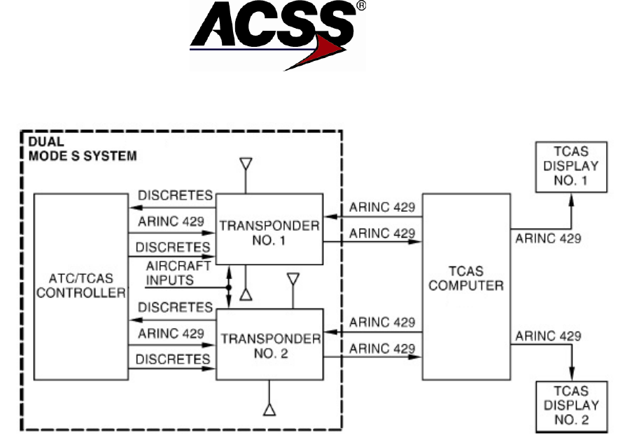
4. General Description
The Line Replaceable Units (LRUs) of the Mode S/ADS-B System include control panels, an
ATCRBS transponder or a second Mode S transponder and antennas. The system complies with
ARINC Characteristic 718A-4 (Mode S) functionality and meets the requirements of TSO-C112d,
Air Traffic Control Radar Beacon System/Mode S (ATCRBS/Mode S) Airborne Equipment.
The Mode S/ADS-B system is made up of a Mode S/ADS-B transponder accompanied by an
ATCRBS transponder or a second Mode S/ADS-B transponder, a control panel, and antennas. If
the transponder is used with the TCAS, top and bottom omnidirectional antennas are required. If
the transponder is used alone as surveillance, a bottom omnidirectional antenna is sufficient.
Figure 1-2 details the signals and overall interconnects associated with the NXT-600 Transponder
installation. Figure 1-3 shows a high-level interconnect (optional) used to switch between the
single pair of antennas in a dual Mode S installation.
A. Purpose of System
Mode S is a cooperative surveillance and communication system for air traffic control. It
employs ground-based sensors (interrogators) and airborne transponders. Ground-air-
ground data link communications can be accommodated integrally with the surveillance
interrogations and replies. Mode S has been designed as an evolutionary addition to the
ATCRBS to supply the enhanced surveillance and communication capability required for
air traffic control automation.
To facilitate the introduction of Mode S into the ATCRBS, both ground and airborne Mode
S installations include full ATCRBS capability. Mode S interrogators supply surveillance
of ATCRBS-equipped aircraft and Mode S transponders reply to ATCRBS interrogators.
The data link capability of Mode S allows it to serve as an essential element of the Traffic
Alert and Collision Avoidance System (TCAS) II. All TCAS II avoidance maneuvers are
coordinated through the Mode S System. In addition, the Mode S transponder is
responsible for reporting pressure altitude data and, through its control panel, supplies
manual control of the TCAS unit.
Pub. No. 8600600-001, Revision 001 34-52-13 1-9
26 Mar 2014
Use or disclosure of information on this page is subject to the restrictions in the proprietary notice of this document.

SYSTEM DESCRIPTION AND INSTALLATION MANUAL
NXT-600 Mode S/ADS-B Transponder/Part No. 9006000
A principal feature of the Mode S system that differs from ATCRBS is that each aircraft is
assigned a unique address code. Using this unique code, interrogations can be directed
to a particular aircraft and replies can be positively identified. Channel interference is
minimized because a sensor can limit its interrogations to targets of interest. By proper
timing of interrogations, replies from closely spaced aircraft can be received without
mutual interference. The unique address in each interrogation and reply also permits the
inclusion of data-link messages to or from a particular aircraft.
For the purpose of Automatic Dependant Surveillance-Broadcast, the NXT-600
transponder will transmit a set of squitters including Airborne Position (BDS 0,5), Surface
Position (BDS 0,6), Status (BDS 0,7), Aircraft ID and Category (BDS 0,8), and Airborne
Velocity (BDS 0,9).
Figure 1-2: Basic Mode S System Interconnection
1-10
26 Mar 2014 34-52-13 Pub. No. 8600600-001, Revision 001
Use or disclosure of information on this page is subject to the restrictions in the proprietary notice of this document.
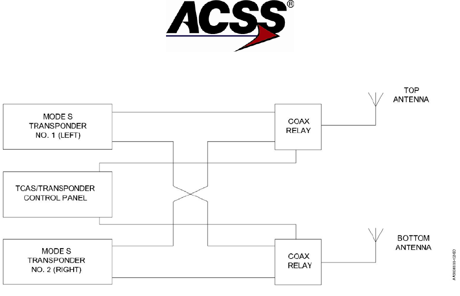
SYSTEM DESCRIPTION AND INSTALLATION MANUAL
NXT-600 Mode S/ADS-B Transponder/Part No. 9006000
Figure 1-3: Switch Transponder Antennas
5. Component Descriptions
A. NXT-600 Mode S/ADS-B Transponder
The NXT-600 transponder is mounted remotely in the aircraft and electrically interfaces to the
aircraft systems via three connectors on the rear of the unit. J1 is a 106-pin ARINC 404
connector that interfaces to +28 V dc power, a mode controller, program pin strapping,
pressure altitude source(s), and optionally to a TCAS computer, selected altitude source,
GPS source(s), aircraft heading source(s), and onboard maintenance computer(s). J2 and
J3 are RF connectors through which the transponder receives interrogations at 1030 MHz
and transmits replies and squitters at 1090 MHz via two coaxial cable interfaces to top and
bottom mounted omni directional antennas.
Figure 1-4 shows a graphical view of the NXT-600 Mode S/ADS-B Transponder. Table 1-6
lists leading particulars for the transponder.
Pub. No. 8600600-001, Revision 001 34-52-13 1-11
26 Mar 2014
Use or disclosure of information on this page is subject to the restrictions in the proprietary notice of this document.
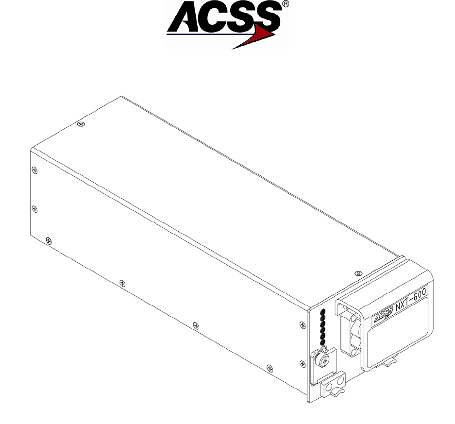
SYSTEM DESCRIPTION AND INSTALLATION MANUAL
NXT-600 Mode S/ADS-B Transponder/Part No. 9006000
Figure 1-4: NXT-600 Mode S/ADS-B Transponder
1-12
26 Mar 2014 34-52-13 Pub. No. 8600600-001, Revision 001
Use or disclosure of information on this page is subject to the restrictions in the proprietary notice of this document.

SYSTEM DESCRIPTION AND INSTALLATION MANUAL
NXT-600 Mode S/ADS-B Transponder/Part No. 9006000
Table 1-6: NXT-600 Mode S/ADS-B Transponder Leading Particulars
Item Specification
Dimensions (maximum):
● Length
14.09 in. (355.85 mm)
● Width
4.15 in. (104.14 mm)
● Height
3.44 in. (86.36 mm)
Weight (maximum)
5.2 lbs (2.36 kg)
Power Requirements:
● Operating Voltage +18.0 V to +30.3 V dc (+27.5 V dc nominal)
● Current
Receive mode: 1 A nominal at 27.5 V dc
Transmit mode: 2 A nominal at 27.5 V dc
● Power Consumption:
- Standby Mode (No Replies)
28 Watts nominal at +27.5 V dc
- Active Mode (Maximum Load)
55 Watts maximum at +27.5 V dc
● External Circuit Breaker Rating 5 A at +27.5 V dc
Cooling Requirements
Fan installed on unit
Tray Connector Kit
ACSS Part No. 7510359-910
Mounting MT-600 Tray Assembly, Part No. 9516000-001
TSO
Refer to Table 1-2 for Part Numbers & Applicable
TSO.
ETSO
Refer to Table 1-2 for Part Numbers & Applicable
ETSO.
Environmental Specifications
DO-160G, Refer to Table 1-7
Operating Modes:
● STANDBY
Ready but not replying
● ATC ON
Transponder Modes A, C, and S; no altitude reporting
● ATC ALT
Transponder Modes A, C, S, and ADS-B; altitude
reporting is enabled
Transmitter Frequency
1090 ±0.5 MHz
Transmitter Power
500 Watts peak pulse maximum, 250 Watts minimum
Receiver Frequency
1030 MHz
Minimum Trigger Level (MTL)
-77 ±3 dBm
Mutual Suppression
Bidirectional, accepts +18 to +70 V dc pulse input,
provides +28 V dc nominal output
Controller Interface:
● Circuit Configuration
Two ARINC 429 control data input ports. 12.5k
bits/sec (low-speed).
● Bus Protocol
Bus protocol meets requirements defined in ARINC
718A-4 for receiving transponder and TCAS control
information.
Pub. No. 8600600-001, Revision 001 34-52-13 1-13
26 Mar 2014
Use or disclosure of information on this page is subject to the restrictions in the proprietary notice of this document.

SYSTEM DESCRIPTION AND INSTALLATION MANUAL
NXT-600 Mode S/ADS-B Transponder/Part No. 9006000
Table 1-6: NXT-600 Mode S/ADS-B Transponder Leading Particulars (cont)
Item Specification
TCAS II Interface:
● Circuit Configuration
ARINC 429 input and output bus. 100k bits/sec (high-
speed).
● Bus Protocol
Bus protocol meets requirements defined in ARINC
718A-4 and ARINC 735B for Standard transponder to
TCAS bus interface.
Airborne Data Link Processor (ADLP)
Interface:
● Circuit Configuration
COMM-A/B messages have an ARINC 429 input and
output bus. COMM-C messages have an ARINC 429
input and output bus. Both sets of buses are 100k
bits/sec (high-speed).
● Bus protocol
Bus protocol meets requirements defined in ARINC
718A-4 for Standard transponder to ADLP bus
interface.
Elementary Surveillance (ELS) Function:
When the transponder is connected to the
appropriate onboard sources (e.g., ADC, ADIRU,
control panel, FMS, etc.) specific data is extracted by
the transponder (e.g., uncorrected pressure altitude
in 25 ft increments, flight ID, flight status (in air/on
ground), etc.). The ELS function transmits replies
with this data along with the strapped/strobed 24-bit
aircraft address and the transponder's capability
report to ground-based interrogators.
● Digital Air Data Interface
ARINC 429 and ARINC 575 label 203 uncorrected
pressure altitude are accepted. ARINC 429 or ARINC
575 data format, 12.5k bits/sec (low-speed). Two
redundant digital air data inputs are provided. A
discrete input to switch to the second digital air data
source is provided.
● Flight Identification (Flight ID) Interface
ARINC 429 labels 233, 234, 235, 236, and 360 are
accepted. ARINC label 237 if present is ignored. The
interface to the transponder can be with a
FID/ATC/TCAS or FID control panel or from a FMS.
ARINC 429 data format, 12.5k bits/sec (low-speed).
● Aircraft Air/Ground Status Interface
Two open/ground discrete inputs are provided to
indicate to the transponder the aircraft's air/ground
status.
● 24-bit Aircraft Address Interface
Eight open/ground/strobed program pins wired to
either one common (ground), or six strobed ouputs
are provided to indicate to the transponder the
aircraft's unique 24-bit aircraft address.
1-14
26 Mar 2014 34-52-13 Pub. No. 8600600-001, Revision 001
Use or disclosure of information on this page is subject to the restrictions in the proprietary notice of this document.

SYSTEM DESCRIPTION AND INSTALLATION MANUAL
NXT-600 Mode S/ADS-B Transponder/Part No. 9006000
Table 1-6: NXT-600 Mode S/ADS-B Transponder Leading Particulars (cont)
Item Specification
Downlink Airborne Parameters (DAPS) / EHS
Function:
When the transponder is connected to the
appropriate onboard sources (e.g., GNSS, ADC,
LRU, ADIRU, MCP/FCU, etc.) specific data is
extracted by the transponder (e.g., lat/long position,
E/W and N/S velocities, track angle rate, selected
altitude, etc.). The DAPS function transmits replies
with this data to ground-based and airborne
interrogators (EHS) and also broadcasts to ground-
based and airborne receivers with 1090 Extended
Squitters.
● Mode Control Panel/Flight Control Unit
(MCP/FCU) Interface
ARINC 429 labels 101, 102, 233, 234, 235, 235 are
accepted. 102 is accepted as long as the
configuration discrete do not indicate GAMA. ARINC
429 data format, 12.5k bits/sec (low-speed) or 100 k
bits/sec (high-speed). The transponder automatically
detects whether the data is low-speed or high-speed
format.
● ARINC 743 Global Positioning System
(GPS) Interface
ARINC 429 labels 076, 103, 110, 111, 112, 120, 121,
130, 136, 140, 145, 150, 165, 166, 174, 247, and 370
are accepted. ARINC 429 data format, 12.5k bits/sec
(low-speed) or 100k bits/sec (high-speed). The
transponder automatically detects whether the data is
low-speed or high-speed format.
● Inertial Reference System/Flight
Management System (IRS/FMS) Interface
ARINC 429 labels 101, 102, 312, 313, 314, 320, 325,
335 and 365 are accepted. ARINC 429 data format,
12.5k bits/sec (low-speed) or 100k bits/sec (high-
speed). The transponder automatically detects
whether the data is low-speed or high-speed format.
● Digital Air Data Computer (ADC) Interface
ARINC 429 and ARINC 575 low-speed labels 203,
204, 205, 206, 210, 212, 234 and 236 are accepted.
Two redundant digital air data inputs are provided. A
discrete input to switch to the second digital air data
source is provided.
● Extended Squitter Disable Interface
A discrete input to disable the transmission extended
squitters/DO-260B is provided.
Onboard Software Uploading/
Fault Log Downloading:
● Circuit Configuration
Data Loading/Maintenance Interface through RJ-45
front panel connector.
● Bus Protocol
The data transfer protocol for the RJ-45 RS-232 front
panel connection is XMODEM 1K.
Pub. No. 8600600-001, Revision 001 34-52-13 1-15
26 Mar 2014
Use or disclosure of information on this page is subject to the restrictions in the proprietary notice of this document.

SYSTEM DESCRIPTION AND INSTALLATION MANUAL
NXT-600 Mode S/ADS-B Transponder/Part No. 9006000
Table 1-7: NXT-600 Transponder DO-160G Categories
Condition
Category
Description of Conducted Test
4 Temperature and Altitude
In-Flight Loss of Cooling
CAT A2F2
CAT Y
Partial temperature control
pressurized location, pressures no
lower than 15,000 feet MSL,
unpressurized locations with
altitude not to exceed 15,000 MSL
Sea level to 70,000 feet
+70 degrees C for 300 minutes
5 Temperature Variation
CAT B
-55 to +70 degrees C
6 Humidity
CAT B
Severe Humidity Environment
7 Operational Shocks and
Crash Safety
CAT E
Low frequency operational shock
and low frequency crash safety.
8 Vibration
CAT RBB1
Fixed Wing, Zone 2-
Robust Vibration – Curve B and
B1
SM
Standard – Curve M
9 Explosion Proofness
CAT E
10 Waterproofness CAT W
11 Fluids Susceptibility CAT X
12 Sand and Dust
CAT X
13 Fungus Resistance
CAT F
Analysis Doc. 8010042-001
14 Salt Fog
CAT X
15 Magnetic Effect CAT Z
16 Power Input CAT BXX
B for DC Power Inputs
X for DC Current Ripple, alternate
test
X for DC Inrush Current Test,
alternate test
17 Voltage Spike
CAT A
18 Audio Frequency
Conducted Susceptibility
– Power Inputs
+28 V dc: CAT Z
19 Induced Signal
Susceptibility
CAT CC
20 Radio Frequency
Susceptibility
CAT M
CAT R
Radiated Susceptibility
Conducted Susceptibility
1-16
26 Mar 2014 34-52-13 Pub. No. 8600600-001, Revision 001
Use or disclosure of information on this page is subject to the restrictions in the proprietary notice of this document.
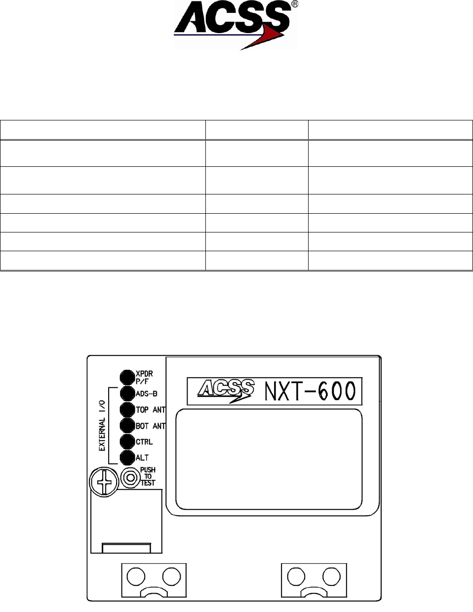
SYSTEM DESCRIPTION AND INSTALLATION MANUAL
NXT-600 Mode S/ADS-B Transponder/Part No. 9006000
Table 1-7: NXT-600 Transponder DO-160G Categories (cont)
Condition
Category
Description of Conducted Test
21 Emission of Radio
Frequency Energy
CAT M
22 Lightning Induced
Transient Susceptibility
CAT A3H3L3
A4
23 Lightning, Direct Effects
CAT X
No test required
24 Icing
CAT X
No test required
25 Electrostatic Discharge
CAT A
26 Flammability
CAT C
Analysis Doc. 8010037-001
B. NXT-600 Front Panel Description
The NXT-600 front panel includes connections to the front panel test switch, access door
to RS-232 Connector (RJ-45) and status lamps. Figure 1-5 shows front panel layout, and
Table 1-8 defines the purpose of each status lamp.
Figure 1-5: NXT-600 Front Panel
Pub. No. 8600600-001, Revision 001 34-52-13 1-17
26 Mar 2014
Use or disclosure of information on this page is subject to the restrictions in the proprietary notice of this document.
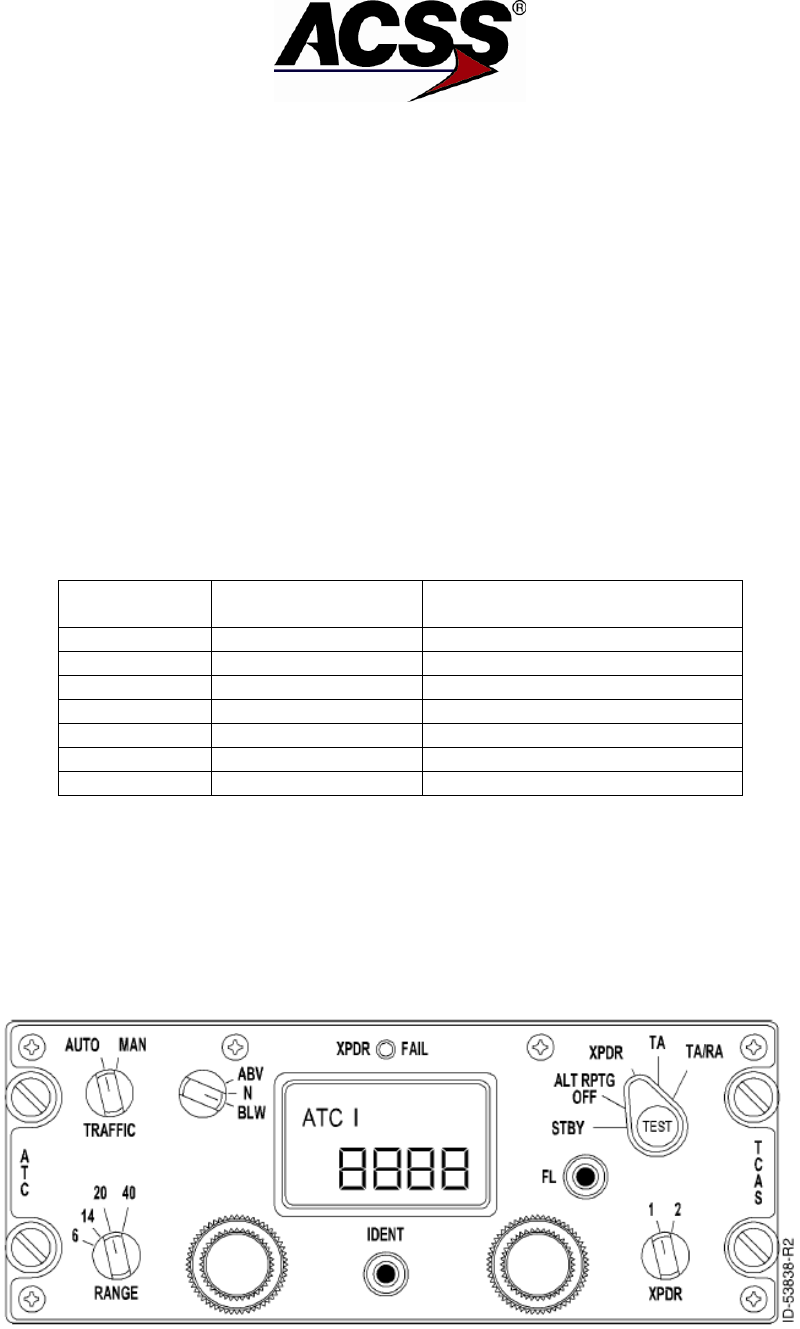
SYSTEM DESCRIPTION AND INSTALLATION MANUAL
NXT-600 Mode S/ADS-B Transponder/Part No. 9006000
On power-up, or if self-test is initiated by PUSH TO TEST button, all lamps default to
“ON” state (Green for XPDR P/F, Red for the rest). After successfully passing Power-on
Test, all lamps switch OFF. See Section 6 of this Manual for detailed lamp fault
diagnostic.
”PUSH TO TEST” momentary button initiates self-test, and can be activated ON
GROUND only.
Access door to RS-232 Connector (RJ-45) is attached to the Front Panel, and opens by
loosening a screw. No tools are required to open the access door.
The front panel is equipped with a handle for safe convenient handling while inserting,
removing or, carrying the NXT-600 Transponder. There is a cooling fan mounted
underneath the handle, so it is advised not to put fingers under the handle until
Transponder powers down.
Table 1-8: Front Panel Lamp Definition
Position
Name
(Labeled)
LED or Switch Type
1
XPDR P/F
Green/Red, Bi-Color
2
ADS-B
Red Lamp, single color
3
TOP ANT
Red Lamp, single color
4
BOT ANT
Red Lamp, single color
5
CTRL
Red Lamp, single color
6
ALT
Red Lamp, single color
Below Lamp’s
PUSH TO TEST
Momentary Switch
C. Gables Dual Mode and Control Panel Figures
The Gables control panel for the transponder and TCAS systems supply mode control for
dual or single ATC Mode S transponder and TCAS II system.
For more information on Gables G7130 Control Panels, refer to the applicable Gables
Installation Manual.
Figure 1-6: Gables G7130 Series Control Panel
1-18
26 Mar 2014 34-52-13 Pub. No. 8600600-001, Revision 001
Use or disclosure of information on this page is subject to the restrictions in the proprietary notice of this document.

SYSTEM DESCRIPTION AND INSTALLATION MANUAL
NXT-600 Mode S/ADS-B Transponder/Part No. 9006000
Table 1-9: Gables G7130 Control Panel Leading Particulars
Item
Specification
Dimensions (maximum):
● Height
2.25 in. (57.2 mm)
● Weight
5.75 in. (146.1 mm)
● Length
5.80 in. (147.3 mm)
Weight (maximum)
2.0 lb (0.907 kg) (Gables units)
Power Requirements:
● Primary
+28 ±4 V dc, 0.25 A maximum
current
● Lighting
5 V, 400 Hz, 2.3 A maximum
Mating Connectors:
● J1
M83723/75R16247 or equivalent
● J2 (Dual Mode S transponder Version)
M83723/75R16248 or equivalent
Mounting
Unit Dzus Fasteners
D. Gables Control Panel Functions
The G7130 for the Mode S System supplies mode control for the ATC transponders, as
well as TCAS commands to the TCAS computer and displays. Figure 1-6 shows only
one of the numerous variants for the G7130 series of ATC/TCAS control panels.
Communication with the Mode S transponders is accomplished via an ARINC 429 bus as
defined in ARINC characteristic 718A-4. Control panel functions include 4096 ident code
selection and display, altitude source and reporting inhibit selection, and selection
between two onboard transponders. A listing of the possible control panel functions
follow.
(1) ALT RPTG OFF, Altitude Source 1-2 Selection
On the Mode Select knob, a position defined as ALT OFF disables altitude
reporting in transponders replies. Other selections to the right of this position will
enable altitude reporting. Altitude source can be selected from the control panel
using different methods. Capabilities within the control panel allow users to use
a two position rotary switch, or a dedicated ALT key. Using a push button key
basically toggles between ADC 1 and ADC 2. Selection is displayed in the
control panel.
Pub. No. 8600600-001, Revision 001 34-52-13 1-19
26 Mar 2014
Use or disclosure of information on this page is subject to the restrictions in the proprietary notice of this document.

SYSTEM DESCRIPTION AND INSTALLATION MANUAL
NXT-600 Mode S/ADS-B Transponder/Part No. 9006000
(2) XPDR FAIL Front Panel Indicator
The XPDR FAIL annunciator displays the functional status of the active
transponder. The fail annunciator lights during one of three situations:
(a) When a failed transponder is selected on the XPDR 1-2 switch.
(b) When own-aircraft navigation and position information from a GPS
(utilized for ADS-B transmissions) is not available for the selected
transponder.
(c) When the antenna diversity required by TCAS II cannot be guaranteed
due to a failure in the antenna BITE monitor.
NOTE: For (a) above, TCAS functionality is affected and results in a
TCAS FAIL message on the TCAS display, as well as a TCAS
FAIL annunciation during self-test.
For (b) above, all other XPDR functionality is not affected.
ADS-B transmissions continue but will be without GPS position
data. TCAS functionality is not affected and will remain
available. Refer to Section 6 Fault Isolation for troubleshooting
prior to removing the transponder for a XPDR FAIL indication.
Installations with EFBs and/or OMS pages will have a separate
fault annunciation.
For (c) above, a TCAS FAIL and ATC FAIL is indicated.
Selecting TCAS STBY or TA Only will clear the FAIL
indications. During this case the NXT-600 is still functioning
through the non-FAIL antenna.
(3) ATC Front Panel Indicator
The ATC/TCAS control panel shall have a dead front white ATC indicator
controlled by the ATC mode key to annunciate activation of the ATC mode.
(4) ALT Front Panel Indicator (Operations)
The ATC/TCAS control panel shall have a dead front amber ALT indicator
controlled by the transponder to annunciate an altitude failure condition.
(5) Mode Control Knob
The mode control knob disables reply capability in the STANDBY mode. It
enables Mode S transponder in the XPDR position. TA and TA/RA modes
support the operation of a TCAS system providing traffic and resolution
advisories.
(6) XPNDR 1-2 Select Knob
The XPDR knob selects which transponder (1 or 2) is used for reporting replies.
(7) TRAFFIC Display Mode Selection – AUTO-ON
TRAFFIC displays can be set in two modes. In the AUTO mode the VSI/TCAS
displays are in the pop up mode. Should a nearby traffic create a threat
condition, then the displays will be turned ON. In the ON mode, all traffic within
the range capabilities will be displayed. The G7130s provides the capability of
selection TRAFFIC modes by using a rotary switch or a dedicated TFC push
button switch.
1-20
26 Mar 2014 34-52-13 Pub. No. 8600600-001, Revision 001
Use or disclosure of information on this page is subject to the restrictions in the proprietary notice of this document.

SYSTEM DESCRIPTION AND INSTALLATION MANUAL
NXT-600 Mode S/ADS-B Transponder/Part No. 9006000
(8) TCAS Test Button
The TCAS TEST button activates a system functional test as well as an internal
test in the control panel. During this test, the control panel displays BIT
information for each electronic module within the control panel.
(9) IDENT Button
The IDENT key is a momentary button. Upon activation, the Special Position
Identifier (SPI) pulse shall be transmitted to ground controllers, in accordance
with ARINC 718A-4, when replying to ATCRBS Mode A or Mode S UF-4 and UF-
5 interrogations for a period of 18 ±1 seconds. The SPI pulse can be reinitiated
at any time.
(10) 4096 Code
The 4096 code can be entered by means of a front panel controls. 4096 code
entry can be described as follows:
● Use the rotary dials to select the ATC code. The ATC indicator is illuminated
and display shows the last 4-digit ATC code entered when the ATC mode is
selected.
● The ATC code can be set to any values from 0000 to 7777. To set an ATC
code, use the keypad buttons 0 thru 7 to enter a 4-digit code.
NOTE: Do not use codes 7500, 7600 or 7700 these codes are reserved for
emergency operation.
● The new ATC code will be transmitted after 5 seconds. If you press the
IDENT button before 5 seconds has elapsed, the new code will be
transmitted immediately.
● If you press the IDENT button while the code entered is incomplete (if the
code has less than 4 digits), the incomplete code is not transmitted and the
previously transmitted code will re-appear on the display.
(11) ABV/N/BLW Function
The G7490 series provides capabilities to select the ABV/N/BLW function via a
rotary switch, or a dedicated push button switch defined as A/N/B.
ABV (Above) Mode – The TCAS system will only display and provide traffic
information for targets located between 9900 feet above and 2700 feet
below your aircraft (+9900 ft and -2700 ft relative to your aircraft).
N (Normal Mode) – In the Normal mode, the TCAS system will only display and
provide traffic information for targets located between 2700 feet above
and 2700 feet below your aircraft (+2700 ft and -2700 ft relative to your
aircraft).
BLW (Below) – The TCAS system will only display and provide traffic
information for targets located between 2700 feet above and 9900 feet
below your aircraft (+2700 ft and -9900 ft relative to your aircraft).
(12) Flight Level Function
The G7130 series has the capability of selecting the Flight Level function. A
dedicated push button switch “FL” operates as follows:
Pub. No. 8600600-001, Revision 001 34-52-13 1-21
26 Mar 2014
Use or disclosure of information on this page is subject to the restrictions in the proprietary notice of this document.

SYSTEM DESCRIPTION AND INSTALLATION MANUAL
NXT-600 Mode S/ADS-B Transponder/Part No. 9006000
● FL key not pressed: Flight Level bit is transmitted as 0 commanding the
displays to show Relative Flight Level.
● FL key pressed: Flight Level bit is transmitted as 1 commanding the displays
to show Absolute Flight Level. Absolute mode will be transmitted from the
control panel for as long as the FL push button is pressed.
(13) Range Selection
The G7130 is capable of providing a combination of range values based on
specific installation provided. For this purpose range can be selected via a rotary
switch, two push button keys defined as RNG+ and RNG-, or by means of a
dedicated range key defined as RANGE.
Possible range selections from the control panel are:
● 6-14-20-40-80-120
6. Functional Description and Operation
The Mode S Data Link System can be configured with either one or two Mode S transponders. The
system provides air traffic information to Mode S and ATCRBS ground stations to aid in air traffic
control. The Mode S System does all of the following:
● Receives ATCRBS interrogations (ground-to-air) and transmits ATCRBS replies (air-to-
ground)
● Receives Mode S interrogations (ground-to-air) and transmits Mode S replies (air-to-ground)
● Receives TCAS interrogations (air-to-air) and transmits Mode S replies (air-to-air).
● Receives ELS/EHS interrogations (ground-to-air) and transmits ELS/EHS replies (air-to-
ground).
● Receives and processes onboard navigation data and transmits Extended Squitters (air-to-
air, air-to-ground).
Although TCAS is beyond the scope of this manual, it is mentioned to further clarify the capability of
the Mode S System.
A. Functional Operation
(1) Mode A and Mode C
An ATCRBS transponder responds to ATCRBS interrogations with a Mode A
(4096 code) reply or Mode C (altitude status) reply contingent upon the type of
interrogation received. Interrogations are received by the transponder on 1030
MHz and replies are transmitted by the transponder on 1090 MHz. All ATCRBS
transmissions are between the ground station and aircraft.
(2) Stand-Alone Mode S or Mode S in Conjunction with TCAS
A Mode S transponder receives and transmits on the same frequencies as the
ATCRBS transponder and can receive and transmit ATCRBS interrogations and
replies. However, the Mode S transponder was developed for Mode S operation
and can function alone as Mode S or in conjunction with TCAS. When
functioning alone as Mode S, all Mode S transmissions are between the ground
1-22
26 Mar 2014 34-52-13 Pub. No. 8600600-001, Revision 001
Use or disclosure of information on this page is subject to the restrictions in the proprietary notice of this document.

SYSTEM DESCRIPTION AND INSTALLATION MANUAL
NXT-600 Mode S/ADS-B Transponder/Part No. 9006000
station and aircraft. When functioning in conjunction with TCAS, transmissions
may also be from aircraft to aircraft.
(3) Transponder Self-Test
Mode S System operation begins when aircraft power is applied. Initial self-test is
performed automatically upon power-up and is completed in approximately 1
second. Self-testing of the system occurs continuously while in the power-on
mode. If a transponder failure occurs, it is indicated on the control panel. Other
failures are indicated via front panel-mounted lamps on the transponder;
however, these failure indications are not available to the pilot. All failures,
whether hard or intermittent, are recorded in the transponder non-volatile fault log
for analysis by maintenance personnel.
(4) 4096 Code and Mode S Address
After power-up, the pilot enters the assigned 4096 code via the control panel.
This code is the ATC identification code for that aircraft and is used during
ATCRBS (Mode A) interrogations and replies. Mode S interrogations and replies
use a 24-bit address code entered into transponder memory automatically upon
power-up. Each aircraft has its own unique address that is permanently
programmed to the airframe. No manual entry of this address is available.
(5) Reply Capability Disabled
The system can be placed in STANDBY mode. When the STANDBY mode is
selected, the transponder reply transmit capability (Mode S or ATCRBS) is
disabled. The remainder of the transponder functions are operational, including
Built-In Test (BIT). STANDBY mode is typically engaged while on the ground to
prevent unnecessary RF radiation. The STANDBY mode is disengaged just prior
to takeoff and engaged again upon landing. In addition, an air/ground switch,
which functions as part of the Weight-On-Wheels (WOW) circuitry, can disable
ATCRBS transponder reply capability while the aircraft is on the ground if this
feature has been enabled. To disable ATCRBS or ground replies with the
air/ground switch, the appropriate air/ground transponder discrete must be
connected. Refer to Section 4 Loading/Gradient of this manual for details on this
interface. Mode S transponder replies and squitters, however, are not disabled
by the air/ground switch, and aircraft status (on ground or airborne) is included in
the Mode S reply and squitter data.
(6) Transponder Selection
In a dual Mode S transponder installation, the pilot can choose either
transponder from the control panel. Only one transponder is enabled at a time. If
a transponder failure occurs, the XPDR FAIL indicator on the control panel lights;
however, the failed transponder must be the one selected on the control panel for
the indicator to light. Switching between the transponders occurs without loss of
system function.
(7) Special Position Identifier Transmission
A Special Position Identifier (SPI) is added to the ATCRBS and Mode S replies
when the control panel IDENT button is pressed and released. The SPI is
enabled for approximately 18 seconds and supplies the ground station with a
more positive aircraft identification capability. This function is typically activated
upon verbal command from the ground station.
Pub. No. 8600600-001, Revision 001 34-52-13 1-23
26 Mar 2014
Use or disclosure of information on this page is subject to the restrictions in the proprietary notice of this document.

SYSTEM DESCRIPTION AND INSTALLATION MANUAL
NXT-600 Mode S/ADS-B Transponder/Part No. 9006000
(8) Altitude Switching
Dual altitude input ports are supplied for each transponder; the capability to
switch between the two is supplied by a switch on the control panel. This
function lets the pilot select an alternate altitude source if the first fails. It also
lets the ground station verbally verify one source against the other.
B. Mode S/ATCRBS Interrogations and Replies
(1) Identification Code and Baro Altitude
The Air Traffic Control Radar Beacon System (ATCRBS) has been in operation
for several decades. Its purpose is to ensure safe separation and operation of
aircraft, especially in busy terminal areas. ATCRBS transponder-equipped
aircraft transmit replies to interrogations from ground-based sensors
(interrogators). Depending on the type of interrogation, the reply contains either
the identification code currently assigned to the aircraft by ATC (Mode A) or
uncorrected barometric altitude with 100-foot resolution (Mode C).
(2) Range and Relative Bearing
The ground station uses reply delay time to compute range to within
approximately 500 feet. The current angle of the rotating ground antenna
determines azimuth. There is an 18 ±2 second duration SPI pulse to aid in
identifying specific aircraft. Thus, ATC is provided with the information required
to ensure safe separation of aircraft.
(3) Assigned Code Number - ATCRBS
The digits of the assigned code number indicate the code groups to be used and
the pulse coding within each group. The assigned code is a four-digit octal
number (any of 4096) in which the first or left-most digit designates the A group;
the second digit designates the B group; the third digit designates the C group;
and the last or right-most digit designates the D group. Typical information
pulses present in assigned reply codes are given in Table 1-10.
1-24
26 Mar 2014 34-52-13 Pub. No. 8600600-001, Revision 001
Use or disclosure of information on this page is subject to the restrictions in the proprietary notice of this document.

SYSTEM DESCRIPTION AND INSTALLATION MANUAL
NXT-600 Mode S/ADS-B Transponder/Part No. 9006000
Table 1-10: Typical ATCRBS Reply Code Numbers
4096 Code Number
Information Pulses
4096 Code Number
Information Pulses
0000
0001
0002
0003
0004
0005
0006
0007
None
D1
D2
D1, D2
D4
D1, D4
D2, D4
D1, D2, D4
3000
3100
3200
3300
3400
3500
3600
3700
A1, A2
A1, A2, B1
A1, A2, B2
A1, A2, B1, B2
A1, A2, B4
A1, A2, B1, B4
A1, A2, B2, B4
A1, A2, B1, B2, B4
0010
0020
0030
0040
0050
0060
0070
C1
C2
C1, C2
C4
C1, C4
C2, C4
C1, C2, C4
4000
4100
4200
4300
4400
4500
4600
4700
A4
A4, B1
A4, B2
A4, B1, B2
A4, B4
A4, B1, B4
A4, B2, B4
A4, B1, B2, B4
0100
0200
0300
0400
0500
0600
0700
B1
B2
B1, B2
B4
B1, B4
B2, B4
B1, B2, B4
5000
5100
5200
5300
5400
5500
5600
5700
A1, A4
A1, A4, B1
A1, A4, B2
A1, A4, B1, B2
A1, A4, B4
A1, A4, B1, B4
A1, A4, B2, B4
A1, A4, B1, B2, B4
1000
1100
1200
1300
1400
1500
1600
1700
A1
A1, B1
A1, B2
A1, B1, B2
A1, B4
A1, B1, B4
A1, B2, B4
A1, B1, B2, B4
6000
6100
6200
6300
6400
6500
6600
6700
A2, A4
A2, A4, B1
A2, A4, B2
A2, A4, B1, B2
A2, A4, B4
A2, A4, B1, B4
A2, A4, B2, B4
A2, A4, B1, B2, B4
2000
2100
2200
2300
2400
2500
2600
2700
A2
A2, B1
A2, B2
A2, B1, B2
A2, B4
A2, B1, B4
A2, B2, B4
A2, B1, B2, B4
7000
7100
7200
7300
7400
7500
7600
7700
A1, A2, A4
A1, A2,A4, B1
A1, A2, A4, B2
A1, A2,A4, B1, B2
A1, A2, A4, B4
A1, A2,A4, B1, B4
A1, A2,A4, B2, B4
A1, A2,A4, B1, B2,
B4
Pub. No. 8600600-001, Revision 001 34-52-13 1-25
26 Mar 2014
Use or disclosure of information on this page is subject to the restrictions in the proprietary notice of this document.

SYSTEM DESCRIPTION AND INSTALLATION MANUAL
NXT-600 Mode S/ADS-B Transponder/Part No. 9006000
1) Mode Select
Air traffic density has significantly increased since the inception of ATCRBS.
Aircraft within the same approximate range and azimuth from the interrogator
may interfere with each other's replies. Much verbal communication is also
needed to coordinate ATC, creating more traffic on communication channels.
This also places a heavier burden on the air traffic controllers.
Mode Select (Mode S) has been designed as an evolutionary addition to
ATCRBS to supply enhanced surveillance as well as data communication
capability for ATC, with greater degree of automation in mind. Ground-air-ground
data link communications can be accommodated with the surveillance
interrogations and replies, permitting use of the transponder for a number of
different ATC functions. Messages can be either 56 or 112 bits in length. The
same transmit and receive frequencies are used as for ATCRBS.
(a) Ground and Airborne Installations
1. Mode S Compatibility with ATCRBS
To facilitate the introduction of Mode S into ATCRBS, both ground
and airborne Mode S installations include full ATCRBS capability.
Mode S interrogators supply surveillance of older ATCRBS-equipped
aircraft, and Mode S transponders reply to ATCRBS interrogators.
Mode S interrogators are able to command Mode S transponders not
to reply to compatible ATCRBS-only interrogations. They are also
able to solicit only Mode S replies from Mode S transponders which
minimizes RF transmissions.
2. Mode S Address
Another unique aspect of Mode S is that each aircraft equipped with
a Mode S transponder is assigned a unique 24-bit address. This
address appears in either a coded or clear form in every Mode S
reply. This not only improves aircraft identification by ATC, but also
permits selective interrogation once the aircraft has been acquired by
an ATCRBS/Mode S or Mode S-only All-Call interrogation.
3. Minimizing RF Channel Loading
Selective interrogation is aimed toward reducing RF channel loading.
Another way to minimize RF traffic is the capability of locking out the
transponder from replying to All-Calls, from either all interrogators or
from specific ones, for 18-second intervals. Including the station's
identity code in the interrogation message enables this lockout.
Probability-based replies make it possible to separate transmissions
from aircraft that would otherwise be garbled when a group of aircraft
might answer a single interrogation.
4. Uplink/Downlink Transmission CRC
All transmissions for surveillance or data communications, from the
ground up to the aircraft (uplink) and from the aircraft down to the
ground (downlink), are protected by a 24-bit Cyclic Redundancy
Code (CRC) error detection scheme, also referred to as parity. In
addition, ground interrogators can perform error correction on
received downlink messages.
1-26
26 Mar 2014 34-52-13 Pub. No. 8600600-001, Revision 001
Use or disclosure of information on this page is subject to the restrictions in the proprietary notice of this document.

SYSTEM DESCRIPTION AND INSTALLATION MANUAL
NXT-600 Mode S/ADS-B Transponder/Part No. 9006000
(b) Traffic Alert and Collision Avoidance System
Mode S transponders are an integral part of the Traffic Alert and
Collision Avoidance System (TCAS). TCAS-equipped aircraft are
airborne interrogators, communicating with other TCAS-equipped aircraft
through their Mode S transponders for coordination of collision
avoidance maneuvers. TCAS aircraft acquire other Mode S
transponder-equipped aircraft by receiving squitter transmissions
(unsolicited All-Call type replies, transmitted pseudo-randomly every 0.8
to 1.2 seconds with aircraft Mode S address), and thereafter by specific
addressed interrogations. Although either Mode S or ATCRBS Mode C
transponders aid TCAS-equipped aircraft in avoiding collisions,
coordination of collision avoidance maneuvers is possible between two
aircraft only if both are Mode S and TCAS equipped.
(c) Mode S Message
1. Interrogation and Reply Formats
Mode S features have been added to the ATCRBS already in place.
This procedure ensures that the older airborne transponders and the
ground-based interrogators used in the ATCRBS are still functional.
The Mode S signal formats used for this combined system operation
include ATCRBS/Mode S All-Call [Mode A, Mode C, and Mode S],
Mode S interrogation, Mode S SLS and Mode S reply.
2. Interrogation Pulses and Timing
The uplink Mode S format for the interrogation pulse group consists
of pulses designated P1, P2, and P3. The time spacing between the
P1 and P3 pulses determines the type of interrogation (Mode A
aircraft identification or Mode C altitude reporting). Pulse P2, which
follows P1 by 2 microseconds, is used for Side Lobe Suppression
(SLS) in the ATCRBS. The amplitude of P2 is recognized by the
airborne transponder as either a main beam or SLS interrogation.
With Mode S interrogation, the basic P1 and P3 pulse system is
extended to include a P4 pulse, which follows P3 by 2 microseconds.
The P4 pulse uses the same spacing as between P1 and P2.
However, P4 has an additional feature in that its pulse width can be
either 1.6 microseconds or 0.8 microsecond, whereas the P1 and P3
pulse widths are always 0.8 microsecond.
3. Replies to All-Call Interrogations and Pulse Width
In operation, when a standard ATCRBS transponder receives this
interrogation of P1, P3, and P4 pulses, it responds with the ATCRBS
reply, which consists of 14 pulses that carry the identity code or the
altitude code. The P4 pulse is ignored since the ATCRBS
transponder circuit is designed so that it does not recognize the P4
pulse. The response is dependent upon the presence and length of
P4. When a standard P1 and P3 interrogation is received from an
ATCRBS interrogator (no P4), the Mode S transponder responds
with a standard ATCRBS reply. An uplink interrogation pulse group,
which includes a P4 pulse, makes the Mode S transponder prepare
to measure the P4 pulse width. As soon as the Mode S transponder
detects the rising edge of the P4 pulse, it disables its ATCRBS reply.
Pub. No. 8600600-001, Revision 001 34-52-13 1-27
26 Mar 2014
Use or disclosure of information on this page is subject to the restrictions in the proprietary notice of this document.

SYSTEM DESCRIPTION AND INSTALLATION MANUAL
NXT-600 Mode S/ADS-B Transponder/Part No. 9006000
It then looks for a pulse width of 0.8 or 1.6 microseconds. A pulse
width of 0.8 microsecond is recognized by the Mode S transponder
as an uplink ATCRBS-only All-Call, and it does not respond at all. In
this case, the ground station is looking for all the aircraft in the
vicinity that are equipped with ATCRBS only. In the case of a 1.6-
microsecond pulse width, the Mode S interrogator wants the Mode S
transponder to respond with the Mode S All-Call coded reply. In this
case, the interrogator receives the aircraft's identity, which is the
unique number that is given to the Mode S-equipped aircraft. The
1.6-microsecond pulse width is in fact an All-Call interrogation for
both ATCRBS and Mode S transponders, eliciting both ATCRBS and
Mode S replies. There is no interrogation addressing in this case as
each system responds within its own capability.
4. Mode S Interrogation
The final type of uplink interrogation is made up of P1 and P2 pulses
of equal amplitude followed by a long pulse of constant amplitude
called P6. This is a Mode S interrogation pulse (P6) that occurs 1.5
microseconds after P2. When the P1 and P2 pulses are of equal
amplitude, the standard ATCRBS transponders see the P2 pulse and
do not respond, since they interpret this as a side lobe interrogation.
5. Mode S Short/Long Interrogation Messages
The Mode S transponder sees the P1 and P2 pulses and prepares to
receive P6 and the uplink Mode S message. There are two types of
messages that are defined in terms of length. The first type of
interrogation is a short message and is 56 bits long; the second is a
long message and is 112 bits long.
(d) Mode S Reply Timing
1. Reply Trigger Point
For the ATCRBS/Mode S All-Calls, the timing reference, or trigger
point, for the Mode S reply is from the leading edge of pulse P4.
From pulse P4, the response time for a Mode S reply is 128 ±0.5
microseconds. When responding to a standard ATCRBS
interrogation, the timing reference is the leading edge of pulse P3
and the ATCRBS response time is 3 microseconds.
2. P6 Phase Encoding
The Mode S Interrogation signal contains equal amplitude P1 and P2
pulses, in addition to the video pulse P6 that contains the Mode S
uplink message phase encoded information.
3. Sync Phase Reversal
Inside the P6 pulse, the first phase change occurs 1.25
microseconds into the pulse. This phase change is called the Sync
Phase Reversal (SPR), and it is used to synchronize the transponder
with the ground station. The SPR is used as the timing reference for
the Mode S reply for uplink messages. Response time is 128 ±0.25
microseconds.
1-28
26 Mar 2014 34-52-13 Pub. No. 8600600-001, Revision 001
Use or disclosure of information on this page is subject to the restrictions in the proprietary notice of this document.

SYSTEM DESCRIPTION AND INSTALLATION MANUAL
NXT-600 Mode S/ADS-B Transponder/Part No. 9006000
4. Differential Phase Shift Keying
All the possible phase changes (chips), corresponding to the data
bits, are inside the P6 pulse and occur after the SPR. Since the
uplink message consists of 4 megabits per second, it means that
there is a possible phase change (chip) every 0.25 microsecond.
This process is called Differential Phase Shift Keying (DPSK). If
there is a one in the data stream, the phase changes. However, if
there is a zero in the data stream, it does not change.
5. Short Message Interrogations
All of the short 56-bit Mode S uplink messages have the following
two things in common:
● The first five bits are always the Uplink Format (UF) number. For
example, in a UF=0, the first five bits are all zero (00000); in a
UF=5, the first five bits are 00101. Downlink messages are
identified by the abbreviation DF for Downlink Format.
● The last 24 bits are an address/parity field. This is a means of
addressing the uplink message (interrogation) and it is also a
means of error detection. The last 24 bits do not carry data, but
rather the unique address of the aircraft overlaid with the parity
bits. A CRC system is actually used for the entire uplink
message. The transponder starts to handle the uplink message
only when it ensures that the message is intended for the aircraft
in which the transponder is installed.
6. Mode S All-Call
The uplink message can be a broadcast-type message intended for
all aircraft in range of the ground station. This is the Mode S-only
All-Call message, which is a special format (UF=11) that contains an
all-ones address.
7. Side Lobe Suppression
Mode S SLS is handled by a P5 pulse, which has a pulse width of
0.8 microsecond. P5 is transmitted simultaneously with the P6 Sync
Phase Reversal (SPR); the P5 pulse subsequently covers the SPR.
When this occurs, the decoder in the receiver cannot see the SPR
and, therefore, does not process the uplink message. This decoding
procedure is different from the ATCRBS method where the amplitude
of the P2 pulse must actually be detected for SLS.
8. Mode S Reply Pulses
The Mode S reply is then generated either in response to a Mode S
interrogation or by one of the ATCRBS/Mode S All-Calls. The reply
includes a preamble made up of two pairs of pulses that occur 8
microseconds before the first Mode S downlink pulse. The preamble
precedes the actual data on the downlink message, much like the
P1, P2, and P6 pulses precede the uplink message.
Pub. No. 8600600-001, Revision 001 34-52-13 1-29
26 Mar 2014
Use or disclosure of information on this page is subject to the restrictions in the proprietary notice of this document.

SYSTEM DESCRIPTION AND INSTALLATION MANUAL
NXT-600 Mode S/ADS-B Transponder/Part No. 9006000
9. UF and DF Messages
There are two fundamental differences between the uplink message
and the downlink message, as follows:
● The uplink burst is at 4 megabits per second, while the downlink
is at 1 megabit per second.
● The uplink uses DPSK, while the downlink uses Pulse Position
Modulation (PPM). Using PPM, there is one pulse for every bit,
either in the first half or the second half of the bit interval
(window). The first half of the window represents a 1; the
second half of the window represents a 0.
10. Mode S Reply Delay
The reply delay time for Mode S is 128 microseconds with respect to
the P6 SPR. This is true for both long and short messages.
However, the downlink message data cannot be prepared until the
uplink message is complete. There is an additional derived timing
specification that indicates how much time is available from the end
of an interrogation until the reply starts. For a short message, it is
113 microseconds; for a long message, it is 99 microseconds. The
basic Mode S transponder handles only the short messages, but this
timing shows that a data link transponder, which handles long
messages, has more data to process and a shorter time to prepare
the message.
C. Mode S ELS/EHS and ADS-B OUT
Traditional Secondary Surveillance Radar (SSR) includes Mode 3/A (aircraft identification
or 4096 code) and Mode C (uncorrected barometric altitude reporting). Then to increase
ATC capacity which included implementing TCAS operation, Mode S was developed
which made transponder interrogations addressable and transponder replies more
accurate and reliable. Basic Mode S requires the aircraft to be;
● equipped with a Mode S capable transponder
● equipped with a means for the operator to enter the ATC assigned 4096 code that
then provides standard ARINC 429 label 016 Mode S Control
● equipped with a source of uncorrected barometric altitude with at least 25 feet
resolution via one of the following:
- standard ARINC 429 label 203 Uncorrected Barometric Altitude
- standard ARINC 575 label 203 Uncorrected Barometric Altitude
● strapped/strobed with the aircraft's unique 24-bit ICAO aircraft address.
Mode S Elementary Surveillance (ELS) was the first step of down linking additional
aircraft derived data. In addition to the Mode S aircraft requirements listed above,
minimally Mode S ELS requires the aircraft to be:
● equipped with a Mode S ELS capable transponder
● equipped with a means for the operator to enter Flight Identification that then
provides standard ARINC 429 labels:
- 233, 301 Characters 1 and 2
- 234, 301 Character 3
1-30
26 Mar 2014 34-52-13 Pub. No. 8600600-001, Revision 001
Use or disclosure of information on this page is subject to the restrictions in the proprietary notice of this document.

SYSTEM DESCRIPTION AND INSTALLATION MANUAL
NXT-600 Mode S/ADS-B Transponder/Part No. 9006000
- 234, 302 Character 4
- 235. 302 Characters 5 and 6
- 236 Characters 7 and 8.
Mode S Enhanced Surveillance (EHS) was the second step of down linking additional
aircraft derived data. In addition to the Mode S and Mode S ELS requirements listed
above, minimally Mode S EHS requires the aircraft to be:
● equipped with a Mode S ELS/EHS capable transponder
● equipped with sources of standard ARINC 429 labels;
- 102 Selected Altitude
- 325 Roll Angle
- 103 True Track Angle or 312 Ground Speed
- 335 Track Angle Rate (if available)
- 210 True Airspeed (TAS)
- 320 Magnetic Heading
- 365 Inertial Vertical Velocity
- 205 MACH
- 206 Indicated Airspeed (IAS)
- 212 Barometric Rate
Automatic Dependent Surveillance-Broadcast (ADS-B OUT) is the next step of down
linking additional aircraft derived data. In addition to the Mode S, Mode S ELS, and
Mode S EHS requirements listed above, minimally ADS-B OUT requires the aircraft to
be:
● equipped with a Mode S ELS/EHS and ADS-B OUT capable transponder
● equipped with sources of standard ARINC 429 labels:
- 076 GNSS Altitude (MSL)
- 103 GNSS True Track Angle
- 110 GNSS Latitude, Coarse
- 111 GNSS Longitude, Coarse
- 112 GNSS Ground Speed or else 312 Ground Speed
- 120 GNSS Latitude, Fine
- 121 GNSS Longitude, Fine
- 130 GNSS Horizontal Protection Limit or else 112 Ground Speed or 312 Ground
Speed or else 133 VIL or else 203 Uncorrected Barometric Altitude or 370 GNSS
HAE
- 136 GNSS Vertical Figure of Merit
- 140 GNSS UTC, Fine (binary, “0.200 sec”)
- 150 GNSS UTC (binary, e.g., “12 h 23 m 12 s”)
- 165 GNSS Vertical Velocity
- 166 GNSS N/S Velocity
- 174 GNSS E/W Velocity
- 247 GNSS Horizontal Figure of Merit
- 314 True Heading or else 103 GNSS Track Angle or else 313 True Track Angle
Pub. No. 8600600-001, Revision 001 34-52-13 1-31
26 Mar 2014
Use or disclosure of information on this page is subject to the restrictions in the proprietary notice of this document.
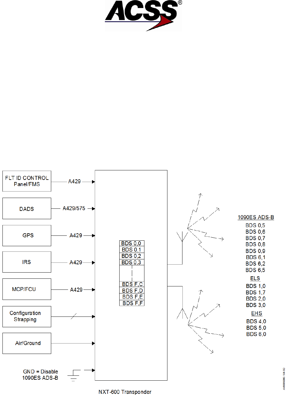
SYSTEM DESCRIPTION AND INSTALLATION MANUAL
NXT-600 Mode S/ADS-B Transponder/Part No. 9006000
- 370 GNSS Geodetic Height (above WGS-84 ellipsoid).
(1) BDS Registers
The transponder assembles data into Binary Data Store (BDS) registers. These
registers are also referred to as GICB registers since they can be down linked via
Ground Initiated Comm B transactions.
The transponder's 256 BDS registers are commonly notated in hexadecimal
format with the first register notated as BDS 0,0 (0016 or 0 decimal) and the last
register notated as BDS F, F (FF16 or 255 decimal). Each BDS register consists
of 56 bits as specified in the ICAO Manual of Mode S Specific Services and
Mode S Standard and Recommended Practices (SARPs). Each BDS register
contains the data payload of a specific Mode S reply or extended squitter.
Registers not updated within a fixed time are cleared, i.e. filled with 0's.
Refer to Figure 1-7 for a simplified block diagram of DAPS Data Processing.
Figure 1-7: NXT-600 Transponder DAPS Data Processing
1-32
26 Mar 2014 34-52-13 Pub. No. 8600600-001, Revision 001
Use or disclosure of information on this page is subject to the restrictions in the proprietary notice of this document.

SYSTEM DESCRIPTION AND INSTALLATION MANUAL
NXT-600 Mode S/ADS-B Transponder/Part No. 9006000
BDS registers currently specific to 1090 ES ADS-B are:
● 0,5 Airborne Position
● 0,6 Surface Position
● 0,7 Status
● 0,8 Aircraft ID and Category
● 0,9 Airborne Velocity
● 6,1 Emergency/Priority Status
● 6,2 Target State and Status
● 6,5 Aircraft Operational Status, Airborne
● 6,5 Aircraft Operational Status, Surface
NOTE: 1090 ES ADS-B BDS data is transmitted in the ME field of DF 17.
BDS registers currently specific to Elementary Surveillance (ELS) are:
● 1,0 Data Link Capability
● 1,7 Common Usage GICB Capability
● 2,0 Aircraft Identification
● 3,0 ACAS Active Resolution Advisory
NOTE: ELS BDS data is transmitted in the ME field of DF 20 or DF 21.
BDS registers currently specific to Enhanced Surveillance (EHS) are:
● 4,0 Selected Vertical Intent
● 5,0 Track and Turn
● 6,0 Heading and Speed
NOTE: EHS BDS data is transmitted in the MB field of DF 20 or DF 21.
(2) Detailed BDS Register Descriptions
This section provides a detailed description of the BDS register data currently
specific to 1090 ES ADS-B, ELS, and EHS. The first column in each of the BDS
register tables that follow provides the number of bits allocated for each
parameter listed that is listed in the second column. The third column provides
typical transponder ramp tester parameter data. The fourth and last column
provides the external sources and details that are required by the transponder to
effectively assemble each parameter into the BDS register.
Refer to ICAO Annex 10, Vol III, Part 1, Chapter 5 and RTCA DO-260B for more
details.
Pub. No. 8600600-001, Revision 001 34-52-13 1-33
26 Mar 2014
Use or disclosure of information on this page is subject to the restrictions in the proprietary notice of this document.

SYSTEM DESCRIPTION AND INSTALLATION MANUAL
NXT-600 Mode S/ADS-B Transponder/Part No. 9006000
Table 1-11: BDS 0,5 Airborne Position
Bits
Parameter
Parameter Data
External Source(s)
1-5
Format Type Code
0, 9-18, 20-22
See NOTE:
6-7
Surveillance Status
NO INFO
PERM ALERT
TEMP ALERT
SPI
Label 016 from ATC/TCAS control
panel.
8
Single Antenna Flag (SAF)
SINGLE
DUAL
9-20
Barometric altitude
or
GNSS Altitude
Decoded Barometric
Altitude in feet
Decoded HAE in feet.
Label 203 uncorrected pressure
altitude from ADC.
Label 370 HAE from GPS
21
Time
N/UTC (Not UTC)
UTC
Time mark from GPS.
22
CPR Format
EVEN
ODD
Label 150 UTC Coarse, Label 140
UTC Fine, and Label 141 UTC
Fine Fraction from GPS
23-39
Encoded
Latitude
Decoded CPR format in
degrees, minutes, and
seconds
Label 110 Latitude (coarse) and
Label 120 Latitude (fine) from GPS
1 or 2 (Best HIL value)
40-46
Encoded
Longitude
Decoded CPR format in
degrees, minutes, and
seconds
Label 111 Longitude (coarse) and
Label 121 Longitude (fine) from
GPS 1 or 2 (best HIL value)
NOTE: Label 130 HIL from GPS or Label 171 RNP from FMS or IRS,
or else Label 112 Ground Speed from GPS or Label 312 Ground Speed from FMS or IRS,
or else Label 133 VIL from GPS,
or else Label 203 Baro Altitude from ADC or label 370 HAE from GPS.
1-34
26 Mar 2014 34-52-13 Pub. No. 8600600-001, Revision 001
Use or disclosure of information on this page is subject to the restrictions in the proprietary notice of this document.

SYSTEM DESCRIPTION AND INSTALLATION MANUAL
NXT-600 Mode S/ADS-B Transponder/Part No. 9006000
Table 1-12: BDS 0,6 Surface Position
Bits
Parameter
Parameter Data
External Source(s)
1-5
Format Type Code
0, 5-8
See NOTE:
6-12
Movement
NO INFO
STOPPED
Speed in Knots
DECELERATING
ACCELERATING
BACKING UP
Label 112 Ground Speed from
GPS 1 or 2 (best HIL value) or
else Label 312 Ground Speed
from IRS or FMS or else derived
from Label 174 E/W and Label
166 N/S velocities.
13
Status Heading
14-20
Heading
N/A
Decoded Heading in
degrees.
Label 314 True Heading from IRS
or else
Label 103 Ground Track from
GPS 1 or 2 (best HIL value) - only
if GS >20 kts or
Label 313 True Track Angle from
IRS only if GS >20 kts.
21
Time
N/UTC (Not UTC)
UTC
22
CPR Format
EVEN
ODD
Label 150 UTC Coarse, Label
140 UTC Fine, and Label 141
UTC Fine Fraction from GPS
23-39
Encoded
Latitude
Decoded CPR format in
degrees, minutes, and
seconds.
Label 110 Latitude (coarse) and
Label 120 Latitude (fine) from
GPS 1 or 2 (best HIL value)
40-56
Encode
Longitude
Decoded CPR format in
degrees, minutes, and
seconds.
Label 111 Longitude (coarse) and
Label 121 Longitude (fine) from
GPS 1 or 2 (best HIL value)
NOTE: Label 130 HIL from GPS or Label 171 RNP from FMS or IRS,
or else Label 112 Ground Speed from GPS or Label 312 Ground Speed from FMS or IRS,
or else Label 133 VIL from GPS,
or else Label 203 Baro Altitude from ADC or label 370 HAE from GPS.
Pub. No. 8600600-001, Revision 001 34-52-13 1-35
26 Mar 2014
Use or disclosure of information on this page is subject to the restrictions in the proprietary notice of this document.

SYSTEM DESCRIPTION AND INSTALLATION MANUAL
NXT-600 Mode S/ADS-B Transponder/Part No. 9006000
Table 1-13: BDS 0,7 Status
Bits
Parameter
Parameter Data
External Source(s)
1-2
Transition Rate
No capability to
determine surface
squitter rate
High surface squitter
rate selected
Low surface squitter
rate selected
Unassigned
Label 110 Latitude (coarse),
Label 111 Longitude (coarse),
Label 120 Latitude (fine), and
Label 121 Longitude (fine) from
GPS.
3
Altitude Type
Barometric Altitude GPS
height above ellipsoid (HAE)
4-56
Reserved
Table 1-14: BDS 0,8 Aircraft ID and Category
Bits
Parameter
Parameter Data
External Source(s)
1-5
Format Type Code
1-4
6-8
Aircraft Category
A, B, C, D
9-14
Character 1
ICAO Character
Label 233 Flight Identifier from
control panel.
15-20
Character 2
ICAO Character
Label 233 Flight Identifier from
control panel.
21-26
Character 3
ICAO Character
Label 234 Flight Identifier from
control panel.
27-32
Character 4
ICAO Character
Label 234 Flight Identifier from
control panel.
33-38
Character 5
ICAO Character
Label 235 Flight Identifier from
control panel.
39-44
Character 6
ICAO Character
Label 235 Flight Identifier from
control panel.
45-50
Character 7
ICAO Character
Label 236 Flight Identifier from
control panel.
51-56
Character 8
ICAO Character
Label 236 Flight Identifier from
control panel.
1-36
26 Mar 2014 34-52-13 Pub. No. 8600600-001, Revision 001
Use or disclosure of information on this page is subject to the restrictions in the proprietary notice of this document.

SYSTEM DESCRIPTION AND INSTALLATION MANUAL
NXT-600 Mode S/ADS-B Transponder/Part No. 9006000
Table 1-15: BDS 0,9 Airborne Velocity Subtypes 1 & 2 – Velocity Over Ground
Bits
Parameter
Parameter Data
External Source(s)
1-5
Format Type Code
19
6-8
Sub Type
1 (Ground Speed Normal)
Label 166 N/S velocity and Label
174 E/W velocity from GPS.
9
Intent Change Flag
10
IFR Capability Flag
11-13
NACv
0, 1, 2, 3, 4.
Label 247 HFOM from GPS.
Label 136 VFOM from GPS.
14
Direction E/W
E
W
15-24
E/W Velocity
N/A
Knots
Label 174 E/W Velocity from GPS
1 or 2 (best HIL value) or
calculated from Label 112 Ground
Speed from GPS, or Label 367
E/W velocity from FMS or IRS.
25
Direction N/S
N
S
26-35
N/S Velocity
N/S
Knots
Label 166 N/S Velocity from GPS
1 or 2 (best HIL value) or
calculated from Label
112 Ground Speed from GPS, or
Label 366 N/S velocity from FMS
or IRS.
36
Source of Vertical
Rate
N/A
BARO
GEO
37
Sign for Vertical Rate
+
-
38-46
Vertical Rate
N/A
Feet per minute
Blended Inertial Vertical Rate
(Label 365) from selected NAV
source or
Barometric Vertical Rate (Label
212) from selected ADC source or
Geometric Vertical Rate (165)
from selected ADS-B Position
Source
Pub. No. 8600600-001, Revision 001 34-52-13 1-37
26 Mar 2014
Use or disclosure of information on this page is subject to the restrictions in the proprietary notice of this document.

SYSTEM DESCRIPTION AND INSTALLATION MANUAL
NXT-600 Mode S/ADS-B Transponder/Part No. 9006000
Table 1-15: BDS 0,9 Airborne Velocity Subtypes 1 & 2 – Velocity Over Ground (cont)
Bits
Parameter
Parameter Data
External Source(s)
47-48
Reserved
49
Difference Sign
+
-
50-56
Difference from
Geo and Baro
Altitudes
Feet
Label 370 Height Above Ellipsoid
(HAE) from GPS 1 or 2 (best HIL
value) or
Label 076 Altitude (MSL) from
GPS 1 or 2 (best HIL value) or
Label 203 Uncorrected
Barometric Altitude from ADC.
NOTE: Subtype 1 is used when NS and EW velocities are valid and both are less than 1022 knots.
Subtype 2 is used when NS and EW velocities are valid and both are greater than 1022 knots.
Table 1-16: BDS 0,9 Airborne Velocity Subtypes 3 & 4 – Airspeed and Heading
Bits
Parameter
Parameter Data
External Source(s)
1-5
Format Type Code
19
6-8
Sub Type
1 (Ground Speed Normal)
Label 166 N/S velocity and Label
174 E/W velocity from GPS.
9
Intent Change Flag
10
IFR Capability Flag
11-13
NACv
0, 1, 2, 3, 4.
Label 247 HFOM from GPS.
Label 136 VFOM from GPS.
14
Status
N/A
Available
15-24
Magnetic
Heading
Degrees
Label 320 Magnetic Heading from
FMS or IRS.
14
Status
N/A
Available
15-24
Magnetic
Heading
Degrees
Label 320 Magnetic Heading from
FMS or IRS.
25
Airspeed Type
IAS
TAS
26-35
Airspeed
N/A
0 to >1021 Knots
0 to >4084 Knots
Label 206 Indicated Airspeed or
Label 210 True Airspeed from
ADC.
1-38
26 Mar 2014 34-52-13 Pub. No. 8600600-001, Revision 001
Use or disclosure of information on this page is subject to the restrictions in the proprietary notice of this document.

SYSTEM DESCRIPTION AND INSTALLATION MANUAL
NXT-600 Mode S/ADS-B Transponder/Part No. 9006000
Table 1-16: BDS 0,9 Airborne Velocity Subtypes 3 & 4 – Airspeed and Heading (cont)
Bits
Parameter
Parameter Data
External Source(s)
36
Source of Vertical
Rate
N/A
BARO
GEO
37
Sign of Vertical Rate
+
-
38-46
Vertical Rate
N/A
Feet per minute
Blended Inertial Vertical Rate
(Label 365) from selected NAV
source or
Barometric Vertical Rate (Label
212) from selected ADC source or
Geometric Vertical Rate (165)
from selected ADS-B Position
Source
47-48
Reserved
49
Difference Sign
+
-
50-56
Difference from
Geo and Baro
Altitudes
Feet
Label 370 Height Above Ellipsoid
(HAE) from GPS 1 or 2 (best HIL
value) or
Label 076 Geometric Altitude from
GPS 1 or 2 (best HIL value) or
Label 203 Baro Altitude from
ADC.
NOTE: Subtype 3 is used when NS and EW velocities are Not valid and Airspeed is less than 1022
knots.
Subtype 4 is used when NS and EW velocities are Not valid and Airspeed is greater than 1022
knots.
Table 1-17: BDS 1,0 Data Link Capability
Bits
Parameter
Parameter Data
External Source(s)
1-8
BDS 1,0 Code
9
Continuation
Flag
0
10-14
Reserved
15
Overlay Command
Capability
0 = No OCC
1 = Transponder has OCC
16
Reserved for
TCAS/ACAS
Pub. No. 8600600-001, Revision 001 34-52-13 1-39
26 Mar 2014
Use or disclosure of information on this page is subject to the restrictions in the proprietary notice of this document.

SYSTEM DESCRIPTION AND INSTALLATION MANUAL
NXT-600 Mode S/ADS-B Transponder/Part No. 9006000
Table 17: BDS 1,0 Data Link Capability (cont)
Bits
Parameter
Parameter Data
External Source(s)
17-23
Mode S Sub
Network Version
Number
0 = Mode S
sub network not
available
1-5 = Version No. 1-5
respectively
6-127 = Not Assigned
24
Transponder
Enhanced
Protocol
Indicator
0 = Level 2-4
1 = Level 5
25
Mode S Specific
Services
Capability
0 = No services available
1 = At least 1 service is
available and valid
26-28
Uplink ELM
Capability
(Comm C)
NO UELM
16/5 ms
16/500 ms
16/250 ms
16/128 ms
16/60 ms
16/30 ms
29-32
Downlink ELM
Capability
NO DELM
4/15
8/15
16/15
16/500 ms
16/250 ms
16/125 ms
33
Aircraft
Identification
Capability
34
Squitter
Capability
Subfield (SCS)
0, 1
35
Surveillance
Identifier (SI)
0, 1
36
Common Usage
GICB Capability
0
1
37-40
Reserved for
ACAS
41-56
DTE
YES
NO
1-40
26 Mar 2014 34-52-13 Pub. No. 8600600-001, Revision 001
Use or disclosure of information on this page is subject to the restrictions in the proprietary notice of this document.

SYSTEM DESCRIPTION AND INSTALLATION MANUAL
NXT-600 Mode S/ADS-B Transponder/Part No. 9006000
Table 1-18: BDS 1,7 Common Usage GICB Capability
Bits
Parameter
Parameter Data
External Source(s)
1
0,5 Extended
Squitter Airborne
Position
0,5
2
0,6 Extended
Squitter Surface
Position
0,6
3
0,7 Extended
Squitter Status
0,7
4
0,8 Extended
Squitter
Identification and
Category
0,8
5
0,9 Extended
Squitter Airborne
Velocity
0,9
6
0,A Extended
Squitter Event
Driven
Information
0,A
7
2,0 Aircraft
Identification
2,0
8
2,1 Aircraft
Registration
9
4,0 Aircraft
Intention
4,0
10
4,1 Next Way- Point
Identifier
11
4,2 Next Way- Point
Position
12
4,3 Next Way-
Point Information
13
4,4
Meteorological
Routine Report
14
4,5
Meteorological
Hazard Report
15
4,8 VHF Channel
Report
Pub. No. 8600600-001, Revision 001 34-52-13 1-41
26 Mar 2014
Use or disclosure of information on this page is subject to the restrictions in the proprietary notice of this document.

SYSTEM DESCRIPTION AND INSTALLATION MANUAL
NXT-600 Mode S/ADS-B Transponder/Part No. 9006000
Table 1-18: BDS 1,7 Common Usage GICB Capability (cont)
Bits
Parameter
Parameter Data
External Source(s)
16
5,0 Track and
Turn Report
5,0
17
5,1 Position
Coarse
5,1
18
5,2 Position Fine
5,2
19
5,3 Air-
Referenced
State Vector
20
5,4 Way-Point 1
21
5,5 Way-Point 2
22
5,6 Way-Point 3
23
5,F Quasi-Static
Parameter
Monitoring
5,F
24
6,0 Heading and
Speed Report
6,0
25-56
Reserved
1-42
26 Mar 2014 34-52-13 Pub. No. 8600600-001, Revision 001
Use or disclosure of information on this page is subject to the restrictions in the proprietary notice of this document.

SYSTEM DESCRIPTION AND INSTALLATION MANUAL
NXT-600 Mode S/ADS-B Transponder/Part No. 9006000
Table 1-19: BDS 2,0 Aircraft Identification
Bits
Parameter
Parameter Data
External Source(s)
1-8
BDS Code 2,0
9-14
Character 1
ICAO Character
Label 233 Flight Identifier from
control panel, or Label 301 Tail
Number from CDFIU.
15-20
Character 2
ICAO Character
Label 233 Flight Identifier from
control panel, or Label 301 Tail
Number from CDFIU.
21-26
Character 3
ICAO Character
Label 234 Flight Identifier from
control panel, or Label 301 Tail
Number from CDFIU.
27-32
Character 4
ICAO Character
Label 234 Flight Identifier from
control panel, or Label 302 Tail
Number from CDFIU.
33-38
Character 5
ICAO Character
Label 235 Flight Identifier from
control panel, or Label 302 Tail
Number from CDFIU.
39-44
Character 6
ICAO Character
Label 235 Flight Identifier from
control panel, or Label 302 Tail
Number from CDFIU.
45-50
Character 7
ICAO Character
Label 236 Flight Identifier from
control panel, or Label 303 Tail
Number from CDFIU.
51-60
Character 8
ICAO Character
Label 236 Flight Identifier from
control panel, or Label 303 Tail
Number from CDFIU.
Pub. No. 8600600-001, Revision 001 34-52-13 1-43
26 Mar 2014
Use or disclosure of information on this page is subject to the restrictions in the proprietary notice of this document.

SYSTEM DESCRIPTION AND INSTALLATION MANUAL
NXT-600 Mode S/ADS-B Transponder/Part No. 9006000
Table 1-20: BDS 3,0 ACAS Active Resolution Advisory
Bits
Parameter
Parameter Data
External Source(s)
1-8
BDS Code 3,0 or 0,0
3,0 = TCAS Bus Valid
0,0 = TCAS Bus Invalid
9-22
Active
Resolution
Advisories
23-26
Resolution
Advisory
Compliment
27
RA Terminated
(RAT)
0
1
28
Multiple Threat
Encounter
0
1
29-30
Threat Type
Indicator (TTI)
0
1
2
31-56
Threat Identity
Data (TID)
Mode S Address of the
threat
1-44
26 Mar 2014 34-52-13 Pub. No. 8600600-001, Revision 001
Use or disclosure of information on this page is subject to the restrictions in the proprietary notice of this document.

SYSTEM DESCRIPTION AND INSTALLATION MANUAL
NXT-600 Mode S/ADS-B Transponder/Part No. 9006000
Table 1-21: BDS 4,0 Selected Vertical Intent
Bits
Parameter
Parameter Data
External Source(s)
1
Status
N/A
Available
2-13
MCP/FCU Selected
Altitude
N/A
Feet
Label 102 Selected Altitude from
MCP/FCU
14
Status
N/A
Available
15-26
FMS Selected Altitude
N/A
Feet
Label 102 Selected Altitude from
FMS.
27
Status
N/A
Available
28-39
Barometric Pressure
Altitude
N/A
Label 203 Baro Alt or Label 234
Baro Alt Correction from ADC or
else Label 273 Baro Pressure
Setting Ref from MCP/ FCU.
40-47
Reserved
48
Status of MCP/FCU
Mode Bits
49
Vertical
Navigation(VNAV)
Mode
YES
NO
50
Altitude Hold Mode
YES
NO
51
Approach Mode
YES
NO
52-53
Reserved
54
Status of Target
Altitude Source
YES
NO
55-56
Target Altitude
Source
N/A
UNKNOWN
AIRCRAFT ALT
FCU/MCP SEL ALT
FMS SEL ALT
Pub. No. 8600600-001, Revision 001 34-52-13 1-45
26 Mar 2014
Use or disclosure of information on this page is subject to the restrictions in the proprietary notice of this document.

SYSTEM DESCRIPTION AND INSTALLATION MANUAL
NXT-600 Mode S/ADS-B Transponder/Part No. 9006000
Table 1-22: BDS 5,0 Track and Turn
Bits
Parameter
Parameter Data
External Source(s)
1
Status
N/A
Available
2
Sign
+
-
3-11
Roll Angle
Degrees
Label 325 Roll Angle from IRS.
12
Status
N/A
Available
13
Sign
+
-
14-23
True Track Angle
Degrees
Label 103 True Track Angle from
GPS or else
Label 313 True Track Angle from
IRS.
24
Status
N/A
Available
25-34
Ground Speed
Knots
Label 112 Ground Speed from
GPS or else
Label 312 Ground Speed from
IRS.
35
Status
N/A
Available
36
Sign
+
-
37-45
Track Angle Rate
Degrees per second
Label 335 Track Angle Rate from
IRS.
46
Status
N/A
Available
47-56
True Airspeed
Knots
Label 210 True Airspeed from
ADC.
1-46
26 Mar 2014 34-52-13 Pub. No. 8600600-001, Revision 001
Use or disclosure of information on this page is subject to the restrictions in the proprietary notice of this document.

SYSTEM DESCRIPTION AND INSTALLATION MANUAL
NXT-600 Mode S/ADS-B Transponder/Part No. 9006000
Table 1-23: BDS 6,0 Heading and Speed
Bits
Parameter
Parameter Data
External Source(s)
1
Status
NA
Available
2
Sign
East
West
3-12
Magnetic
Heading
Degrees
Label 320 Magnetic Heading from
IRS or FMS.
13
Status
NA
Available
14-23
Indicated
Airspeed
Knots
Label 206 Indicated Airspeed
from ADC.
24
Status
NA
Available
25-34
MACH
MACH Number
Label 205 MACH from ADC.
35
Status
NA
Available
36
Sign
+
-
37-45
Barometric
Altitude
Feet per minute
Label 212 Barometric Rate from
ADC.
46
Status
NA
Available
47-
Sign
+
-
48-56
Inertial Vertical
Velocity
Feet per minute
Label 365 Inertial Vertical Velocity
from IRS or FMS.
Table 1-24: BDS 6,1 Extended Squitter, Emergency/Priority Status
Bits
Parameter
Parameter Data
External Source(s)
1-5
Type Code
28
6-8
Subtype Code
1
9-11
Emergency/Priority
Status
0-7
12-24
Mode A Code
Label 016 from Control Panel
25-56
Reserved
Pub. No. 8600600-001, Revision 001 34-52-13 1-47
26 Mar 2014
Use or disclosure of information on this page is subject to the restrictions in the proprietary notice of this document.

SYSTEM DESCRIPTION AND INSTALLATION MANUAL
NXT-600 Mode S/ADS-B Transponder/Part No. 9006000
Table 1-25: BDS 6,2 Extended Squitter, Target State and Status
Bits
Parameter
Parameter Data
External Source(s)
1-5
Type Code
29
6-7
Subtype Code
1
8
SIL Supplement
0, 1
9
Selected Altitude Type
0, 1
10-20
Selected Altitude
0 – 2047
Label 102 Selected Altitude from
MCP/FCU or FMS
21-29
Barometric Altitude
0 – 511
Label 234 Baro Correction (mb)
#1 or Label 236 Baro Correction
(mb) #2
30
Selected Heading
Status
0, 1
31
Selected Heading
Sign
0, 1
32-39
Selected Heading
Label 101 from MCP/FCU or FMS
40-43
NAC
P
0-11
Label 247 Horizontal Figure of
Merit
44
NIC
BARO
0, 1
45-46
SIL
0-3
Label 120 GNSS Latitude Fine,
Label 121 GNSS Longitude, Fine
47
Status of MCP/FCU
Modes
0, 1
48
Autopilot Engaged
0
49
VNAV Mode
0
50
Altitude Hold
0
51
Reserved
52
Approach Mode
0
53
TCAS Operational
0, 1
Label 274 from TCAS
54
LNAV Mode
0
55-56
Reserved
1-48
26 Mar 2014 34-52-13 Pub. No. 8600600-001, Revision 001
Use or disclosure of information on this page is subject to the restrictions in the proprietary notice of this document.

SYSTEM DESCRIPTION AND INSTALLATION MANUAL
NXT-600 Mode S/ADS-B Transponder/Part No. 9006000
Table 1-26: BDS 6,5 Extended Squitter, Aircraft Operational Status, Airborne
Bits
Parameter
Parameter Data
External Source(s)
1-5
Type Code
31
6-8
Subtype Code
0 ,1
9-10
CC Type
0, 1
11
TCAS Operational
0, 1
Label 274 from TCAS
12
1090ES In
0, 1
13-14
Reserved
15
ARV
0, 1
16
TS
0, 1
17-18
TC
0-3
19
UAT In
0, 1
20-24
Reserved
25-26
OM Type
27
TCAS RA Active
0, 1
Label 270 TCAS RA or Label 273
TCAS RA
28
Ident Active
0, 1
Label 016 ATC Control
29
Reserved
30
Single Antenna Flag
0, 1
31-32
SDA
0-3
33-40
Reserved
41-43
Version Number
0-2
44
NIC Supplement A
0-11
Label 130 GPS HIL
45-48
NAC
P
0-11
Label 247 Horizontal Figure of
Merit
49-50
GVA
0-3
Label 136 Vertical Figure of Merit
51-52
SIL
0-3
Label 120 GNSS Latitude Fine,
Label 121 GNSS Longitude, Fine
53
NIC
BARO
0, 1
54
HRD
0, 1
55
SIL Supplement
0, 1
56
Reserved
Pub. No. 8600600-001, Revision 001 34-52-13 1-49
26 Mar 2014
Use or disclosure of information on this page is subject to the restrictions in the proprietary notice of this document.

SYSTEM DESCRIPTION AND INSTALLATION MANUAL
NXT-600 Mode S/ADS-B Transponder/Part No. 9006000
Table 1-27: BDS 6,5 Extended Squitter, Aircraft Operational Status, Surface
Bits
Parameter
Parameter Data
External Source(s)
1-5
Type Code
31
6-8
Subtype Code
0 ,1
9-10
CC Type
0, 1
11
Reserved
12
1090ES In
0, 1
13-14
Reserved
15
B2 Low
0, 1
16
UAT In
0, 1
17-19
NAC
V
0-3
Label 145 Horizontal Velocity
Figure of Merit
20
NIC Supplement C
0, 1
Label 130 GPS HIL
21-24
Length/Width Codes
0-15
25-26
OM Type
27
TCAS RA Active
0, 1
Label 270 TCAS RA or Label 273
TCAS RA
28
Ident Active
0, 1
Label 016 ATC Control
29
Reserved
30
Single Antenna Flag
0, 1
31-32
SDA
0-3
33-40
GPS Antenna Offset
0 ,
41-43
Version Number
0-2
44
NIC Supplement A
0-11
Label 130 GPS HIL
45-48
NAC
P
0-11
Label 247 Horizontal Figure of
Merit
49-50
Reserved
51-52
SIL
0-3
Label 120 GNSS Latitude Fine,
Label 121 GNSS Longitude, Fine
53
Track Angle/Heading
0 = Track Angle
1 = Valid Heading
54
HRD
0 = True
1 = Mag
Type of heading in BDS 0,9
1-50
26 Mar 2014 34-52-13 Pub. No. 8600600-001, Revision 001
Use or disclosure of information on this page is subject to the restrictions in the proprietary notice of this document.

SYSTEM DESCRIPTION AND INSTALLATION MANUAL
NXT-600 Mode S/ADS-B Transponder/Part No. 9006000
Table 1-27: BDS 6,5 Extended Squitter, Aircraft Operational Status, Surface (cont)
Bits
Parameter
Parameter Data
External Source(s)
55
SIL Supplement
0, 1
56
Reserved
D. Mode S Message Format and Data Field Definition
Refer to RTCA DO-181E, DO-185B, DO-218B, and DO-260B for further details of Mode
S Message Formats and Field definitions.
Table 1-28 defines the Mode S interrogation UF (Uplink Format) messages and Table
1-29 defines the Mode S reply DF (Downlink Format) messages. The first 5 bits of the
message indicate the UF/DF type. The message structure including the number of bits
per subfield is included in Table 1-28 and Table 1-29. For example, UF=0 [Binary 00000]
is composed of X:3 (3 bits assigned as padding), RL:1 (1 bit assigned to Reply Length)
etc. The Uplink Format message field descriptions are listed in Table 1-30 and the
Downlink Format message field descriptions are listed in Table 1-31.
Table 1-28: Uplink Format Messages
Uplink Format
Field Description
Message Format with Number of Bits
UF=0 [00000]
Short Air-Air Surveillance
X:3, RL:1, X:4, AQ:1, DS:8, X:10 AP:24
X:Pad
UF=4 [00100]
Surveillance, Altitude Request
PC:3, RR:5, DI:3, SD:16, AP:24
UF=5 [00101]
Surveillance, Identity Request
PC:3, RR:5, DI:3, SD:16, AP:24
UF=11 [01011]
Mode S Only All-Call
PR:4, II/IC:4, CL:3, X:16, AP:24 X:Pad
UF=16 [10000]
Long Air-Air Surveillance
X:3, RL:1, X:4, AQ:1, X:18, MU:56,
AP:24 X:Pad
UF=20 [10100]
Comm-A, Altitude Request
PC:3, RR:5, DI:3, SD:16, MA:56, AP:24
UF=21 [10101]
Comm-A, Identity Request
PC:3, RR:5, DI:3, SD:16, MA:56, AP:24
NOTE: PC, RR, DI, and SD subfields are undefined for UF=20/21 broadcast interrogations.
Pub. No. 8600600-001, Revision 001 34-52-13 1-51
26 Mar 2014
Use or disclosure of information on this page is subject to the restrictions in the proprietary notice of this document.

SYSTEM DESCRIPTION AND INSTALLATION MANUAL
NXT-600 Mode S/ADS-B Transponder/Part No. 9006000
Table 1-29: Downlink Format Messages
Downlink Format
Field Description
Message Format with Number of Bits
DF 0 [00000]
Short Air-Air Surveillance
VS:1, CC:1, X:1, SL:3, X:2, RI:4, X:2,
AC:13, AP:24 X:Pad
DF 4 [00100]
Surveillance, Altitude Reply
FS:3, DR:5, UM:6, AC:13, AP:24
DF 5 [00101]
Surveillance, Identity Reply
FS:3, DR:5, UM:6, ID:13, AP:24
DF 11 [01011]
All-Call Reply
CA:3, AA:24, PI:24
DF 16 [10000]
Long Air-Air Surveillance
VS:1, X:2, SL:3, X:2, RI:4, X:2, AC:13,
MV:56, AP:24 X:Pad
DF 17 [10001]
Extended Squitter (ADS-B)
CA:3, AA:24, ME:56, PI:24
DF 20 [10100]
Comm-B, Altitude Reply
FS:3, DR:5, UM:6, AC:13, MB:56, AP:24
DF 21 [10101]
Comm-B, Identity Reply
FS:3, DR:5, UM:6, ID:13, MB:56, AP:24
Table 1-30: Uplink Format Fields
Designator
Field
Description
AP
Address Parity
24-bit discrete address with parity check
bits overlaid
AQ
Acquisition
Designates formats UF=0, 16 as
acquisition transmissions or non-
acquisition.
CL
Code Label
Identifies the contents of the IC field
DI
Designator Identification
Identifies the coding contained in the SD
field
DS
COMM-B Data Selector
Contains the identity of the ground-
initiated COMM-B register
IC
Interrogator Code
Contains either the II Code or SI Code
II
Interrogator Identification
Identifies the interrogator
MA
Message COMM-A
56-bit uplink field contains messages
directed to the aircraft
MU
Message COMM-U
56-bit uplink field contains information
used in air-to-air exchanges part of the
long special surveillance interrogation
NC
Number of C Segments
Number of segments transmitted in ELM
mode and part of a COMM-C
interrogation
PC
Protocol
Operating commands to the transponder
1-52
26 Mar 2014 34-52-13 Pub. No. 8600600-001, Revision 001
Use or disclosure of information on this page is subject to the restrictions in the proprietary notice of this document.

SYSTEM DESCRIPTION AND INSTALLATION MANUAL
NXT-600 Mode S/ADS-B Transponder/Part No. 9006000
Table 1-30: Uplink Format Fields (cont)
Designator
Field
Description
PR
Probability of Reply
Contains commands to the transponder
which specify the reply probability to the
Mode S only All-Call interrogations
RC
Reply Control
Designates the transmitted segment as
initial, intermediate or final
RL
Reply Length
Commands a reply of DF 0 Short
Message or DF 16 Long Message
RR
Reply Request
Contains length and content of the reply
requested by the interrogators
SD
Special Designator
Contains control codes affecting
transponder protocol
SI
Surveillance Identifier
Defines the surveillance identifier code
Table 1-31: Downlink Format Fields
Designator
Field
Description
AA
Address Announced
Contains the aircraft address
AC
Altitude Code
Field contains the aircraft altitude
AP
Address Parity
24-bit field contains the parity overlaid on
the address
CA
Transponder Capability
Reports transponder communication
capability
CC
Crosslink Capability
Indicates the transponder’s ability to
support crosslink capability
DR
Downlink Request
Requests extraction of downlink
messages from the transponder by the
interrogator
FS
Flight Status
Reports flight status of the aircraft
ID
Identification
Contains the Mode A identification code
reporting the numbers as set by the pilot
MB
Message COMM-B
56-bit MB field contains messages
transmitted to the interrogator
ME
Message Extended Squitter
56-bit downlink field used to broadcast
messages
MV
Message COMM-V
Contains information used in air-to-air
exchanges and is part of the long special
surveillance reply
Pub. No. 8600600-001, Revision 001 34-52-13 1-53
26 Mar 2014
Use or disclosure of information on this page is subject to the restrictions in the proprietary notice of this document.

SYSTEM DESCRIPTION AND INSTALLATION MANUAL
NXT-600 Mode S/ADS-B Transponder/Part No. 9006000
Table 1-31: Downlink Format Fields (cont)
Designator
Field
Description
PI
Parity/Interrogator Identity
24-bit field contains the parity overlaid on
the interrogator’s identity code
RI
Reply Information
4-bit field reports airspeed capability and
the type of reply to the interrogating
aircraft
SL
TCAS Sensitivity Level
This field reports the sensitivity level at
which the TCAS unit is currently
operating
UM
Utility Message
Contains the transponder status
readouts
VS
Vertical Status
Reports the aircraft airborne or on-
ground state
7. System Software Upload/Fault Log Download
The NXT-600 Mode S/ADS-B Transponder has a RJ-45 connector on its front panel. This
connector provides a means to connect to the WebEDDIT software for Software Loading and
Maintenance.
The following functions are supported by the RJ-45 interface:
●Operational Software Upload
●Fault Log Download.
●Software Part Number Verification
A. Software Program Description and Configuration
The NXT-600 transponder's part number contains a 5-digit dash number (9006000-
XXYYY). The first two digits (XX) correspond to the unit's hardware configuration and
functionality. The last three digits (YYY) correspond to the operational software load in
the unit. The unit's label also has a separate hardware and software modification status
table. Changes to the boot software are reflected by a change to either the hardware
portion of the dash number or the hardware modification status. Changes to the
operational software are reflected by a change to either the software portion of the dash
number or the software modification status.
Once software is loaded into the transponder, it is necessary to verify that the correct
software version is loaded in the unit and that the unit's label is remarked with the correct
part number or modification status. The transponder's operational product software part
number uniquely identifies the software load. The following methods may be used to
verify that the correct software part number has been loaded.
●If the aircraft is configured with an ACSS TCAS Computer Unit 4066010-905 or
higher dash number, or an ACSS 7517900-XXXXX and an ACSS 4067241-XXX
VSI/TRA, or a Thales 457400XX-1900, -1901, or -2000 dash number VSI/TCAS unit,
the software part number is displayed on the extended test maintenance pages.
1-54
26 Mar 2014 34-52-13 Pub. No. 8600600-001, Revision 001
Use or disclosure of information on this page is subject to the restrictions in the proprietary notice of this document.

SYSTEM DESCRIPTION AND INSTALLATION MANUAL
NXT-600 Mode S/ADS-B Transponder/Part No. 9006000
● If the aircraft contains an OMS that is connected to the transponder, the software part
number may be displayed on a Multifunction Control Display Unit (MCDU) controller
for the OMS system.
● The software part number may be displayed by connecting a PC with the WebEDDIT
software to the RS-232 port on the transponder's front panel RJ-45 DATA LOADER
connector.
B. WebEDDIT Interface Description
RS-232 PC Interface Description
The RJ-45 connector contains an RS-232 input and output bus interface that may be
connected to a standard serial port on a PC. The RS-232 bus has a Baud Rate of
115,200 Baud, a data size of 8 data bits with 1 stop bit and no parity. ACSS WebEDDIT
software can be used to perform all data transfer functions.
The transponder then expects the software to be transferred in blocks using an
XMODEM 1K communication protocol. The protocol allows for error detection and block
re-transmission during block transfer operations. After a successful software load is
completed, the XPDR PASS indicator on the transponder's front panel is on. A failed
load is annunciated by the XPDR FAIL indicator on the front panel.
The fault log is downloaded by issuing a WebEDDIT download command through the RJ-
45 port. The fault log is then downloaded through an ASCII file transfer.
The WebEDDIT software can capture the data and write it to a file for analysis.
The software part number for the software that is loaded in the unit can be displayed on
the WebEDDIT software. The command displays the part number for the boot and
operational programs, as well as CRCs, the unit part number, and unit serial number.
See Table 1-32 for WebEDDIT user interface commands.
Table 1-32: WebEDDIT User Commands
Test
Input
Output
Software CRC
CR
BOOT xxxx
OPER xxxx
DL xxxx
XIC xxxx
Unit Part Numbers
PN
BOOT S/W x..x
OPER S/W x..x
DL S/W x..x
XIC F/W x..x
COMPAT NUM x..x
UNIT H/W x..x
UNIT SER x..x
Start Software Upload ( on
ground only)
UL
None if the command succeeded,
otherwise an appropriate error
message is displayed.
Start download of maintenance
log
DL
Maintenance Log Downloaded
Pub. No. 8600600-001, Revision 001 34-52-13 1-55
26 Mar 2014
Use or disclosure of information on this page is subject to the restrictions in the proprietary notice of this document.

SYSTEM DESCRIPTION AND INSTALLATION MANUAL
NXT-600 Mode S/ADS-B Transponder/Part No. 9006000
Table 1-32: WebEDDIT User Commands
Test
Input
Output
Start Data Output for Recording
DR
ARINC, Extended Squitter, and
Discrete Data
Stop Data Output for Recording
“ESC” key
Display Configuration Data
DC
CONFIG VALID Note: For Valid
Configurations
**** CONFIG INVALID **** Note:
For Invalid Configurations
GPS ANT OFF = d
AC L/W = d Note: (Display LSB-
MSB)
NACV = d
SDA = d
ADS-B FAIL DISABLE = d
AC CAT = d
PARITY = d Note: Validity
ADS-B RCV CAP = d
VFOM ADJ = d
SDI = d
BARO CORRECT/ALT TYPE = d
TAS = d
MODE S ADDR =aaaaaa
ANT CBL DELAY = d
ANT BITE/RMS 555/GAMA = d
Invalid command
any not
listed above
(including a
blank line)
“INVALID COMMAND”
8. Software Data Uploading and Part Number Verification Procedures
The following paragraphs give the methods and procedures to do a software upload and
verification that the upload was performed correctly. Prior to uploading software, verify the
current Operational software loaded on the transponder unit. Refer to Software Part Number
Verification procedures described in this section. Doing this will help compare the Part Numbers
before and after the new software upload.
A. Software Loading Using a Stand-Alone PC with WebEDDIT
Verify the updated software part number using a stand-alone PC with WebEDDIT
according to the following procedure:
1) Obtain WebEDDIT software Part No. 9000679-007 or later and install the software
on the PC.
2) Obtain a commercially available RJ-45 to serial cable.
3) Shut off the PC.
1-56
26 Mar 2014 34-52-13 Pub. No. 8600600-001, Revision 001
Use or disclosure of information on this page is subject to the restrictions in the proprietary notice of this document.

SYSTEM DESCRIPTION AND INSTALLATION MANUAL
NXT-600 Mode S/ADS-B Transponder/Part No. 9006000
4) Remove power from the NXT-600 Transponder.
5) Connect the serial cable from the PC to the RJ-45 front connector on the NXT-600
Transponder.
6) Apply power to the NXT-600 Transponder.
7) Power on the PC to Microsoft Windows operation.
8) Select WebEDDIT maintenance tool from the desktop.
9) Select “Connect with NXT Transponder” from the Menu Page.
10) Select “Select Upload File” Button
11) Choose the location of the software file to be loaded
12) Click “Open”
13) Select “Upload OP S/W File (UL)”
14) Once upload has completed and NXT has restarted, perform steps 10-16 in section
B below.
B. Software Verification Using a Stand-Alone PC with WebEDDIT
Verify the updated software part number using a stand-alone PC with WebEDDIT
according to the following procedure:
1) Obtain WebEDDIT software Part No. 9000679-007 or later and install the software
on the PC.
2) Obtain a commercially available RJ-45 to serial cable.
3) Shut off the PC.
4) Remove power from the NXT-600 Transponder.
5) Connect the serial cable from the PC to the RJ-45 front connector on the NXT-600
Transponder.
6) Apply power to the NXT-600 Transponder.
7) Power on the PC to Microsoft Windows operation.
8) Select WebEDDIT maintenance tool from the desktop.
9) Select “Connect with NXT Transponder” from the Menu Page.
10) Select “Part Number”.
11) Verify displayed part numbers match what was loaded.
12) Select “S/W CRC”.
13) Verify S/W CRC’s match what was loaded.
14) Shut down the PC and remove power.
15) Remove power from the NXT-600 Transponder.
16) Disconnect the RJ-45 cable from the front connector on the NXT-600 Transponder.
Pub. No. 8600600-001, Revision 001 34-52-13 1-57
26 Mar 2014
Use or disclosure of information on this page is subject to the restrictions in the proprietary notice of this document.

SYSTEM DESCRIPTION AND INSTALLATION MANUAL
NXT-600 Mode S/ADS-B Transponder/Part No. 9006000
9. Fault Log Downloading Procedures
Fault log downloading procedures are used for saving the contents of fault memory for analysis at a
later time, or for aircraft maintenance personnel. Downloading the fault log has no effect on the
operational software load.
A. Fault Log Downloading Using a Stand-Alone PC with WebEDDIT
Verify the updated software part number using a stand-alone PC with WebEDDIT
according to the following procedure:
1) Obtain WebEDDIT software Part No. 9000679-007 or later and install the software
on the PC.
2) Obtain a commercially available RJ-45 to serial cable.
3) Shut off the PC.
4) Remove power from the NXT-600 Transponder.
5) Connect the serial cable from the PC to the RJ-45 front connector on the NXT-600
Transponder.
6) Apply power to the NXT-600 Transponder.
7) Power on the PC to Microsoft Windows operation.
8) Select WebEDDIT maintenance tool from the desktop.
9) Select “Connect with NXT Transponder” from the Menu Page.
10) Select “Dump BITE Log (DL)”.
11) Locate BITE Log file in WebEDDIT_SESSIONS folder on C: drive.
12) Provide to ACSS Customer Service for analysis.
13) Shut down the PC and remove power.
14) Remove power from the NXT-600 Transponder.
15) Disconnect the RJ-45 cable from the front connector on the NXT-600 Transponder.
10. Mode S/ADS-B Configuration Verification Procedures
Mode S/ADS-B Configuration Verification procedures are used for ensuring the installation specific
aircraft parameters are set correctly via the strapping/strobing aircraft wiring.
A. Configuration Verification Using a Stand-Alone PC with WebEDDIT
Verify the configuration strapping/strobing using a stand-alone PC with WebEDDIT
according to the following procedure:
1) Obtain WebEDDIT software Part No. 9000679-007 or later and install the software
on the PC.
2) Obtain a commercially available RJ-45 to serial cable.
3) Shut off the PC.
1-58
26 Mar 2014 34-52-13 Pub. No. 8600600-001, Revision 001
Use or disclosure of information on this page is subject to the restrictions in the proprietary notice of this document.

SYSTEM DESCRIPTION AND INSTALLATION MANUAL
NXT-600 Mode S/ADS-B Transponder/Part No. 9006000
4) Remove power from the NXT-600 Transponder.
5) Connect the serial cable from the PC to the RJ-45 front connector on the NXT-600
Transponder.
6) Apply power to the NXT-600 Transponder.
7) Power on the PC to Microsoft Windows operation.
8) Select WebEDDIT maintenance tool from the desktop.
9) Select “Connect with NXT Transponder” from the Menu Page.
10) Select “Dump Config (DC)”
11) Verify configuration settings match installation requirements
12) Shut down the PC and remove power.
13) Remove power from the NXT-600 Transponder.
14) Disconnect the RJ-45 cable from the front connector on the NXT-600 Transponder.
Pub. No. 8600600-001, Revision 001 34-52-13 1-59
26 Mar 2014
Use or disclosure of information on this page is subject to the restrictions in the proprietary notice of this document.

SYSTEM DESCRIPTION AND INSTALLATION MANUAL
NXT-600 Mode S/ADS-B Transponder/Part No. 9006000
Blank Page
1-60
26 Mar 2014 34-52-13 Pub. No. 8600600-001, Revision 001
Use or disclosure of information on this page is subject to the restrictions in the proprietary notice of this document.

SYSTEM DESCRIPTION AND INSTALLATION MANUAL
NXT-600 Mode S/ADS-B Transponder/Part No. 9006000
MECHANICAL INSTALLATION
1. General
This section contains information on how and where to mount each component of the NXT-600
Mode S/ADS-B Transponder System. For new installations, plan the installation in two stages.
First, determine the location of the line replaceable units (LRU) in the aircraft. Next, determine
the length of RF and electrical interconnections for the selected locations.
2. Equipment and Materials
For new transponder installations, refer to Table 1-1 for Mounting Tray information. For all other
components, refer to the applicable Outline and Installation Diagram in this section for mounting
and mating connector information.
Refer to the Aircraft Maintenance Manual (AMM) for materials necessary to install the
omnidirectional antennas.
3. Mechanical Installation Design
A. Transponder Provisions
Mechanical installation data for the NXT-600 Mode S/ADS-B Transponder is shown in
Figure 2-1. The transponder can be mounted in any convenient location in the aircraft.
The exact location should allow the cabling between the unit, control panel, and antennas
to be as short as possible.
This unit is mounted in an MT-600 Mounting Tray, ACSS Part No. 9516000-001.
Locate the mounting tray to allow adequate space for installation of the transponder and
provide reasonable accessibility for servicing. Allow space on the top, sides, and rear of
the transponder for adequate ventilation. Provide a solid mechanical mount to prevent
vibration amplification. In addition, the location must provide protection from rain,
condensation, solvents, and hydraulic fluid.
Electrically bond the mounting tray to the aircraft airframe by a low resistance path of less
than 2.5 milliohms.
Pub. No. 8600600-001, Revision 001 34-52-13 2-1
26 Mar 2014
Use or disclosure of information on this page is subject to the restrictions in the proprietary notice of this document.

SYSTEM DESCRIPTION AND INSTALLATION MANUAL
NXT-600 Mode S/ADS-B Transponder/Part No. 9006000
Blank Page
2-2
26 Mar 2014 34-52-13 Pub. No. 8600600-001, Revision 001
Use or disclosure of information on this page is subject to the restrictions in the proprietary notice of this document.
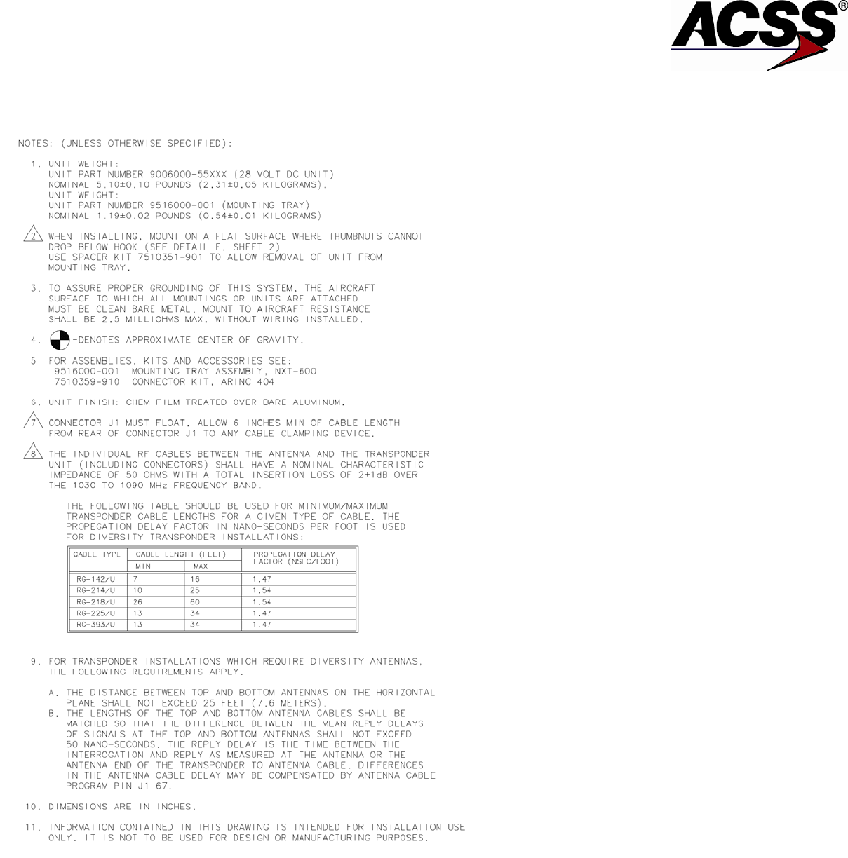
SYSTEM DESCRIPTION AND INSTALLATION MANUAL
NXT-600 Mode S/ADS-B Transponder/Part No. 9006000
Figure 2-1: (Sheet 1): NXT-600 Mode S Transponder Outline and Installation Diagram
Pub. No. 8600600-001, Revision 001 34-52-13 2-3/(2-4 blank)
26 Mar 2014
Use or disclosure of information on this page is subject to the restrictions in the proprietary notice of this document.
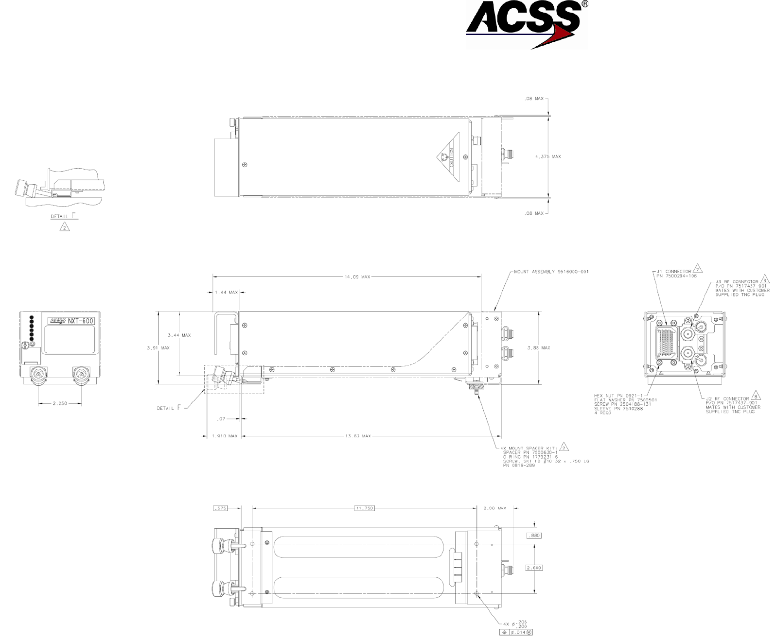
SYSTEM DESCRIPTION AND INSTALLATION MANUAL
NXT-600 Mode S/ADS-B Transponder/Part No. 9006000
Figure 2-1: (Sheet 2) NXT-600 Mode S Transponder Outline and Installation Diagram
Pub. No. 8600600-001, Revision 001 34-52-13 2-5/(2-6 blank)
26 Mar 2014
Use or disclosure of information on this page is subject to the restrictions in the proprietary notice of this document.
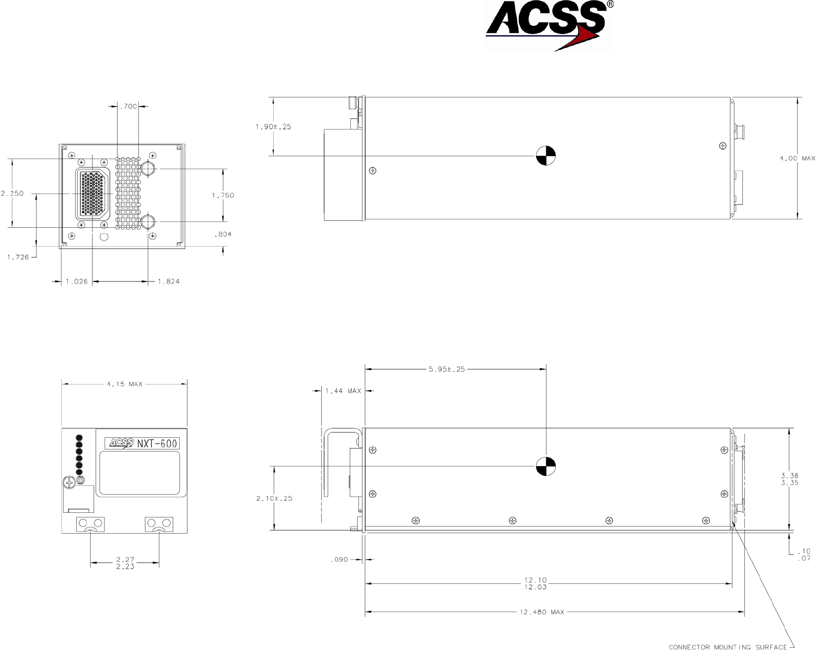
SYSTEM DESCRIPTION AND INSTALLATION MANUAL
NXT-600 Mode S/ADS-B Transponder/Part No. 9006000
Figure 2-1: (Sheet 3) NXT-600 Mode S Transponder Outline and Installation Diagram
Pub. No. 8600600-001, Revision 001 34-52-13 2-7/(2-8 blank)
26 Mar 2014
Use or disclosure of information on this page is subject to the restrictions in the proprietary notice of this document.

SYSTEM DESCRIPTION AND INSTALLATION MANUAL
NXT-600 Mode S/ADS-B Transponder/Part No. 9006000
B. Controller Provisions
An illustration of the mechanical installation data for the ACSS Control Panel is shown in
Figure 2-2. The Control Panel can be purchased in either a dual Mode S transponder
configuration (when two Mode S transponders are to be included in the installation) or a
Mode S/ATCRBS configuration (when only one of the existing ATCRBS transponders is
to be replaced).
Various types of controllers (Radio Management Units or FMS Controllers) can also be
used to control the transponder. The Gables G7491 is a dedicated Flight ID control panel
that can be added to meet ELS requirements without replacing the existing ATC/TCAS
control panel. Refer to that particular unit's Installation Manual for installation data.
Pub. No. 8600600-001, Revision 001 34-52-13 2-9
26 Mar 2014
Use or disclosure of information on this page is subject to the restrictions in the proprietary notice of this document.

SYSTEM DESCRIPTION AND INSTALLATION MANUAL
NXT-600 Mode S/ADS-B Transponder/Part No. 9006000
Blank Page
2-10
26 Mar 2014 34-52-13 Pub. No. 8600600-001, Revision 001
Use or disclosure of information on this page is subject to the restrictions in the proprietary notice of this document.
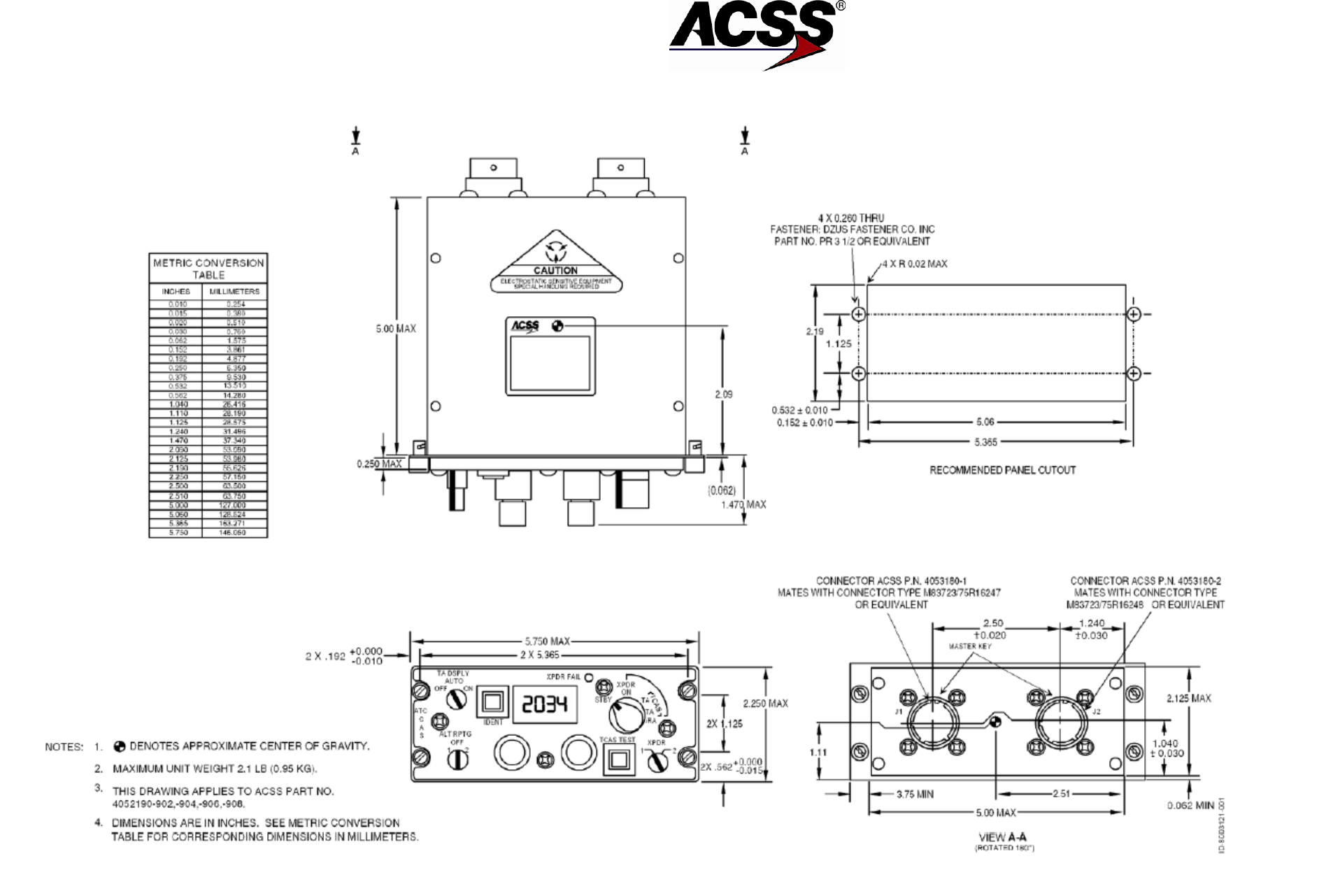
SYSTEM DESCRIPTION AND INSTALLATION MANUAL
NXT-600 Mode S/ADS-B Transponder/Part No. 9006000
Figure 2-2: ACSS Control Panel (Dual Mode S Outline and Installation Diagram)
Pub. No. 8600600-001, Revision 001 34-52-13 2-11/(2-12 blank)
26 Mar 2014
Use or disclosure of information on this page is subject to the restrictions in the proprietary notice of this document.

SYSTEM DESCRIPTION AND INSTALLATION MANUAL
NXT-600 Mode S/ADS-B Transponder/Part No. 9006000
C. Transponder Antenna Provisions
When installing the transponder antennas, a TSO-C112 antenna should be selected. The
antenna must be vertically polarized and operate in the frequency range of 960 to 1220
MHz. Antenna impedance must be 50 ohms. Selection of a grounded or lightning-
protected type antenna is required to pass the transponder bite continuity detection
circuitry, if enabled.
In dual transponder antenna installations, it is important to provide adequate isolation
from each other to prevent receiver front-end damage. A 30-inch desired, 20-inch
minimum, separation of Mode S antennas from other L-band antennas (including TCAS
antennas) must be maintained. The maximum cable length for RG-214/U is 30 feet
(9.144 meters). Allow adequate cable length so bends in the cable have a minimum 3-
inch (76 mm) radius. Selection of coax cable assemblies with moisture barrier protection
is highly recommended to minimize the effects of humidity and corrosion.
When air traffic control (ATC) antennas are installed, the mounting area must provide a
solid mechanical base for the antenna and clearance for the connector. A doubler plate is
usually required when the antenna is mounted on an unsupported large fuselage area.
The aircraft structure should never be weakened for the sake of a good location. Refer to
the aircraft manufacturer’s specifications; reinforcements for antennas are often built into
the aircraft structure.
Doubler plates or shims (if used) must be metallic and shaped to interface the antenna
base with the contour of the aircraft fuselage. All antenna installations should be in
accordance with the manufacturer’s installation instructions.
A weather sealing compound should be applied around the perimeter of the antenna
base to prevent seepage of water and condensation, and to prevent corrosion. If a
sealant or aerodynamic smoother is used, it should be applied after the antenna has
been secured to the fuselage.
D. Antenna Coaxial Cable Requirements
RG-214/U was the classic coaxial cable for transponder applications. However, new
technology coaxial cables are now available that have less signal attenuation per foot,
are smaller in diameter, have a smaller bending radius, weigh less, and are less
flammable.
It is very important that the connectors are correctly installed on the cable to ensure
reliable performance. For this reason, ACSS recommends that installers purchase
antenna cable assemblies, with connectors attached, from reputable cable specialty
suppliers. The cable assemblies are tested for loss and Voltage Standing Wave Ratio
(VSWR) at the operating frequency to ensure proper operation.
Diversity transponder antenna cables have the following requirements:
• The individual RF cables between the antenna and the transponder mounting tray
(including connectors) must have a nominal characteristic impedance of 50 ohms
with a total insertion loss of 2.0 ±1.0 dB at 1030 MHz.
• Maximum antenna cable length is 30 feet.
Pub. No. 8600600-001, Revision 001 34-52-13 2-13
26 Mar 2014
Use or disclosure of information on this page is subject to the restrictions in the proprietary notice of this document.

SYSTEM DESCRIPTION AND INSTALLATION MANUAL
NXT-600 Mode S/ADS-B Transponder/Part No. 9006000
• Top and bottom antenna cable lengths do not have to be equal in length. However,
the distance between top and bottom antennas on the horizontal plane cannot
exceed 25 feet (7.6 meters).
• Coaxial cable must be double shielded.
• A male equivalent of the antenna connector must be attached to the antenna end
and a TNC coax connector must be attached to the transponder mounting tray end.
E. Aircraft Configuration Requirements
The NXT-600 Mode S/ADS-B Transponder has 14 Mode S and 11 ADS-B configuration
pins that must be set to either OPEN, GROUND or 1 of 6 STROBE states specific to
each aircraft. One means of accomplishing this requirement is to use a remotely located,
32 pin or more, connector. Refer to the aircraft AMM/IPL for an approved connector
series to be used. Refer to Section 4 Loading/Gradient of this SDIM for a definition of
these pins.
2-14
26 Mar 2014 34-52-13 Pub. No. 8600600-001, Revision 001
Use or disclosure of information on this page is subject to the restrictions in the proprietary notice of this document.

SYSTEM DESCRIPTION AND INSTALLATION MANUAL
NXT-600 Mode S/ADS-B Transponder/Part No. 9006000
ELECTRICAL INSTALLATION
1. General
This section gives electrical installation procedures, power distribution, and interconnect
information for each component of the NXT-600 Mode S/ADS-B Transponder System installation.
2. Equipment and Materials
Refer to the Outline and Installation Diagrams in Section 2 for mating connector part number
information when doing a new installation.
3. Electrical Installation Procedure
The information necessary to supply the electrical interconnects is shown in Table 3-1 and Table
3-2. Refer to Section 4, Loading/Gradient Specifications, for a list of all the signal names used in
the interconnect diagrams and tables.
NOTE: Refer to ACSS Technical Newsletter 8001227-001, Rev 1 if antenna BITE program
implementation is required for functionality.
4. Electrical Installation
A. NXT-600 Mode S/ADS-B Transponder
The various installation options require different electrical connections as described on
the interconnect diagram and the paragraphs that follow.
The transponder uses air data supplied in one of the following formats:
ARINC 429/575 Air Data
● J1-32/33
● J1-46/47
Air data from one of these source types must be connected to the transponder.
All Mode S transponders require a unique 24-bit code (Mode S address) that is assigned
to each aircraft. The aircraft Mode S (ICAO) address for US (N) registered can be
obtained from the Federal Aviation Administration, Mike Monroney Aeronautical Center,
Aircraft Registration Information, AVN-450, PO Box 25082, Oklahoma City, OK 73125,
Telephone: (405) 680-3116.
If the aircraft is registered in a country other than the United States, contact the aviation
authority of the country in which the aircraft is registered.
Pub. No. 8600600-001, Revision 001 34-52-13 3-1
26 Mar 2014
Use or disclosure of information on this page is subject to the restrictions in the proprietary notice of this document.

SYSTEM DESCRIPTION AND INSTALLATION MANUAL
NXT-600 Mode S/ADS-B Transponder/Part No. 9006000
The Mode S address is usually issued as an 8-digit octal number. To strap the address
code correctly, each digit must be converted to a corresponding binary number. (For
example: 7 octal = 111 binary, 1 octal = 001 binary.)
Once the 8-digit octal code is converted to a 24-bit binary number, the address pins must
be grounded, left open, or strobed according to this binary number representation. Refer
to Section 4, Loading/Gradient Specifications for a definition of these settings.
An example of an octal code number being converted to a binary number is shown
below:
Octal address code = 1 2 3 4 5 6 7 0
In binary this number is: (MSB) 001 010 011 100 101 110 111 000 (LSB)
The assignment of the correct Mode S address is CRITICAL to the proper operation of
the ATC System. If dual Mode S transponders are installed, both transponders must be
programmed to the same Mode S address.
The transponder also uses programming pins to select or deselect various functions and
settings for Mode S and ADS-B functionality. Refer to Section 4, Loading/Gradient
Specifications section to determine applicable installation wiring.
Where more than one pin is shown for 28 volts input, these pins should be connected in
parallel. Also, handle dc ground in the same manner.
3-2
26 Mar 2014 34-52-13 Pub. No. 8600600-001, Revision 001
Use or disclosure of information on this page is subject to the restrictions in the proprietary notice of this document.

SYSTEM DESCRIPTION AND INSTALLATION MANUAL
NXT-600 Mode S/ADS-B Transponder/Part No. 9006000
Table 3-1: NXT-600 Mode S/ADS-B Transponder Interconnect Data
I/O Description Connector Pin Connects To Notes
Spare
J1-1
Spare
J1-2
I/O Mutual Suppression
J1-3 (22) ----S ------S-------
| |
GND
-- ---
GND
L-Band Suppression
Bus 1
(I)
ADS-B Receive Capability
J1-4 (22)----------------------
Gnd/Open/Strobe
4
(I)
A/V Length/Width A
J1-5 (22)----------------------
Gnd/Open/Strobe
4
(I)
A/V Length/Width B
J1-6 (22)----------------------
Gnd/Open/Strobe
4
(I)
XPDR +28 V RTN
J1-7 (22)----------------------
Acft dc Ground
(I)
XPDR +28 V PWR
J1-8 (22)----------------------
Acft 28 V Supply
(I)
XPDR +28 V PWR
J1-9 (22)----------------------
Acft 28 V Supply
(I)
Reserved Discrete #1
J1-10
(I)
GPS Antenna Longitudinal
Offset A
J1-11 (22)----------------------
Gnd/Open/Strobe 4
(I)
GPS Antenna Longitudinal
Offset B
J1-12 (22)---------------------- Gnd/Open/Strobe 4
(I)
Navigation Accuracy
Category for Velocity
(NACV)
J1-13 (22)---------------------- Gnd/Open/Strobe 4
(I)
System Design Assurance
(SDA)
J1-14 (22)---------------------- Gnd/Open/Strobe 4
(I)
ADS-B FAIL Disable
J1-15 (22)----------------------
Gnd/Open
4
(I)
Aircraft Category
J1-16 (22)----------------------
Gnd/Open/Strobe
4
(I)
+28 V dc Return
J1-17 (22)----------------------
Acft dc Ground
(I)
+28 V dc Return
J1-18 (22)----------------------
Acft dc Ground
(I)
Ground
J1-19 (22)----------------------
Acft dc Ground
(I)
Ground
J1-20 (22)----------------------
Acft dc Ground
(I)
Configuration Program Pin
Common
J1-21 (22)---------------------- dc Ground
Spare
J1-22
(O)
XPDR Fail Discrete Output
#1
J1-23 (22)----------------------
Control Panel
(28V/Open)
(I)
Reserved Discrete #2
J1-24
Spare
J1-25
(O) XT Coordination
XPDR to TCAS
429 (A)
J1-26 (22)--------S--T—S----
| |
GND-- --GND
| |
TCAS Computer 2
(O)
XT Coordination
XPDR to TCAS
429 (B)
J1-27 (22)--------
S--T—S----
| |
GND
-- --
GND
TCAS Computer 2
(O)
MSP/ATSU/CMU Out #1 or
Comm A/B
429 (A)
J1-28 (22)--------S--T—S----
| |
Airborne Data Link
Processor 2
Pub. No. 8600600-001, Revision 001 34-52-13 3-3
26 Mar 2014
Use or disclosure of information on this page is subject to the restrictions in the proprietary notice of this document.

SYSTEM DESCRIPTION AND INSTALLATION MANUAL
NXT-600 Mode S/ADS-B Transponder/Part No. 9006000
Table 3-1: NXT-600 Mode S/ADS-B Transponder Interconnect Data (cont)
I/O Description Connector Pin Connects To Notes
(O)
MSP/ATSU/CMU Out #1 or
Comm A/B
429 (B)
J1-29 (22)--------
S--T—S----
| |
GND
-- --
GND
Airborne Data Link
Processor 2
(O)
General Output #1 or
Comm C/D
429 (A)
J1-30 (22)--------S--T—S----
| |
Airborne Data Link
Processor 2
(O)
General Output #1 or
Comm C/D
429 (B)
J1-31 (22)--------S--T—S----
| |
GND
-- --
GND
Airborne Data Link
Processor 2
(I)
Air Data Input #1
429 (A)
J1-32 (22)--------S--T—S----
| |
ARINC 429 or 575
ADC#1
2
(I) Air Data Input #1
429 (B)
J1-33 (22)--------S--T—S----
| |
GND
-- --
GND
ARINC 429 or 575
ADC#1 2
(I)
Control Panel
429 (A)
J1-34 (22)--------S--T—S----
| |
Control Panel 2
(I) Control Panel
429 (B)
J1-35 (22)--------S--T—S----
| |
GND
-- --
GND
Control Panel 2
(I)
FMC #1
429 (A)
J1-36 (22) )-------
S--T—S----
| |
Communication
Management Unit
2
(I) FMC #1
429 (B)
J1-37 (22) )-------
S--T—S----
| |
GND
-- --
GND
Communication
Management Unit 2
(I)
FCC/MCP #1
420 (A)
J1-38 (22) )-------
S--T—S----
| |
Flight Management
System
2
(I) FCC/MCP #1
429 (B)
J1-39 (22) )-------S--T—S----
| |
GND
-- --
GND
Flight Management
System 2
(I) TX Coordination
429 (A)
J1-40 (22)--------S--T—S----
| | TCAS Computer 2
(I) TX Coordination
429 (B)
J1-41 (22) )-------S--T—S----
| |
GND
-- --
GND
TCAS Computer 2
(I) FMC/GNSS #1 In #1 or Comm
A/B
429 (A)
J1-42 (22)--------S--T—S----
| | Airborne Data Link
Processor 2
(I) FMC/GNSS #1 In #1 or Comm
A/B
429 (B)
J1-43 (22)--------S--T—S----
| |
GND-- --GND
Airborne Data Link
Processor 2
(I) IRS/FMS/Data Concentrator In
#1 or Comm C/D
429 (A)
J1-44 (22)--------S--T—S----
| |
Airborne Data Link
Processor 2
(I) IRS/FMS/Data Concentrator In
#1 or Comm C/D
429 (B)
J1-45 (22)--------S--T—S----
| |
GND-- --GND
Airborne Data Link
Processor 2
3-4
26 Mar 2014 34-52-13 Pub. No. 8600600-001, Revision 001
Use or disclosure of information on this page is subject to the restrictions in the proprietary notice of this document.

SYSTEM DESCRIPTION AND INSTALLATION MANUAL
NXT-600 Mode S/ADS-B Transponder/Part No. 9006000
Table 3-1: NXT-600 Mode S/ADS-B Transponder Interconnect Data (cont)
I/O Description Connector Pin Connects To Notes
(I) Air Data Input #2
429 (A)
J1-46 (22) )------S--T—S----
| |
ARINC 429/575
Digital ADC 2
(I) Air Data Input #2
429 (B)
J1-47 (22) )------S--T—S----
| |
GND
-- --
GND
ARINC 429/575
Digital ADC 2
(I) Control Data Port B
429 (A)
J1-48 (22)--------S--T—S----
| | Control Panel 2
(I) Control Data Port B
429 (B)
J1-49 (22)--------S--T—S----
| |
GND
-- --
GND
Control Panel 2
(0)
Control Data Out
429 (A)
J1-50 (22)--------S--T—S----
| |
Control Panel 2, 3
(0) Control Data
429 (B)
J1-51 (22)--------S--T—S----
| |
GND
-- --
GND
Control Panel 2, 3
(I)
VFOM Adjust
J1-52 (22)----------------------
Gnd/Open
4
(I)
Reserved Discrete #3
J1-53
(I)
Reserved Discrete #4
J1-54
(I)
Reserved Discrete #5
J1-55
(I)
Reserved Discrete #6
J1-56
(I)
Reserved Discrete #7
J1-57
(I)
DLP
J1-58 (22) ----------------------
(I)
Extended Squitter Disable
J1-59 (22) ----------------------
Gnd/Open
4
(I) Alt Data Source Select
Discrete Input
J1-60 (22) ---------------------- Gnd/Open 4
(I) Control Data Port Select
Discrete Input
J1-61 (22) ---------------------- Gnd/Open 4
I/O
RS-232 A
J1-62
I/O
RS-232 B
J1-63
(I)
FMC/GNSS #2 In #1
429 (A)
J1-64 (22) )-------
S--T—S----
| |
Flight Management
System
2
(I) FMC/GNSS #2 In #1
429 (B)
J1-65 (22) )-------
S--T—S----
| |
GND
-- --
GND
Flight Management
System 2
(I)
Configuration Parity (2 states)
J1-66 (22) ----------------------
Gnd/Open
4
(I)
Ant Cable / Reserved (8
states)
J1-67 (22) ---------------------- Gnd/Open/Strobe 4
(I)
Antenna BITE/RMS
555/GAMA (8 states)
J1-68 (22) ---------------------- Gnd/Open/Strobe 4
(I)
Reserved Discrete #13
J1-69
(I)
Reserved Discrete #8
J1-70
(I)
Reserved Discrete #9
J1-71
(I)
Standby/On Discrete Input
J1-72 (22) ----------------------
Control Panel
(I) Air/Ground Discrete Input #1 J1-73 (22) ----------------------
Control Panel or Acft
Air/Ground Switch
(I)
Transponder OFF
J1-74 (22) ----------------------
Gnd/Open
Pub. No. 8600600-001, Revision 001 34-52-13 3-5
26 Mar 2014
Use or disclosure of information on this page is subject to the restrictions in the proprietary notice of this document.

SYSTEM DESCRIPTION AND INSTALLATION MANUAL
NXT-600 Mode S/ADS-B Transponder/Part No. 9006000
Table 3-1: NXT-600 Mode S/ADS-B Transponder Interconnect Data (cont)
I/O Description Connector Pin Connects To Notes
(I) Air/Ground Discrete Input #2 J1-75 (22) ----------------------
Control Panel or Acft
Air/Ground Switch
I/O GPS Time Mark #2A
(Provisioned)
J1-76 ----------------------NC
I/O GPS Time Mark #2B
(Provisioned)
J1-77 ----------------------
NC
I/O GPS Time Mark #1A
(Provisioned)
J1-78 ----------------------
NC
I/O GPS Time Mark #1B
(Provisioned)
J1-79 ----------------------
NC
(I)
Mode S Addr A13-A15
J1-80 (22) ----------------------
Gnd/Open/Strobe
4
(I)
Mode S Addr A16-A18
J1-81 (22) ----------------------
Gnd/Open/Strobe
4
(I)
Mode S Addr A19-A21
J1-82 (22) ----------------------
Gnd/Open/Strobe
4
(I)
Mode S Addr A22-A24
J1-83 (22) ----------------------
Gnd/Open/Strobe
4
(I)
Squat Switch / Alt Source
J1-84 (22) ----------------------
Gnd/Open/Strobe
4
(I)
Tuning Source / Parity
J1-85 (22) ----------------------
Gnd/Open/Strobe
4
(I)
Reserved Discrete #10
J1-86
(I)
Reserved Discrete #11
J1-87
(I)
Reserved Discrete #12
J1-88
(I) Range Trigger (NO) – RMS
555 Controller Only
J1-89 (22) ---------------------- Gnd/Open 4
Spare
J1-90
Spare
J1-91
Spare
J1-92
Spare
J1-93
(I)
Max TAS
J1-94 (22) ----------------------
Gnd/Open/Strobe
4
(I)
Mode S Addr A1-A3
J1-95 (22) ----------------------
Gnd/Open/Strobe
4
(I)
Mode S Addr A4-A6
J1-96 (22) ----------------------
Gnd/Open/Strobe
4
(I)
Mode S Addr A7-A9
J1-97 (22) ----------------------
Gnd/Open/Strobe
4
(I)
Mode S Addr A10-A12
J1-98 (22) ----------------------
Gnd/Open/Strobe
4
(O) XPDR Active (Strobe Output
Discrete #1)
J1-99 (22) ----------------------
Antenna Switching
Relay
4
(O) XPDR Fail Discrete Output #2
(Strobe Output Discrete #2)
J1-100 (22) ---------------------- Control Panel/Strobe 4
(O) ADS-B Function Fail Output
(Strobe Output Discrete #3)
J1-101 (22) ---------------------- Control Panel/Strobe 4
(O) Altitude Valid Discrete Output
(Strobe Output Discrete #4)
J1-102 (22) ---------------------- Control Panel/Strobe 4
Spare
J1-103
(O)
Strobe Output Discrete #5
J1-104 (22) ----------------------
Strobe
4
(O)
Strobe Output Discrete #6
J1-105 (22) ----------------------
Strobe
4
-
J1-106
3-6
26 Mar 2014 34-52-13 Pub. No. 8600600-001, Revision 001
Use or disclosure of information on this page is subject to the restrictions in the proprietary notice of this document.

SYSTEM DESCRIPTION AND INSTALLATION MANUAL
NXT-600 Mode S/ADS-B Transponder/Part No. 9006000
Table 3-1: NXT-600 Mode S/ADS-B Transponder Interconnect Data (cont)
I/O Description Connector Pin Connects To Notes
(I)
Bottom Antenna RF Input
J2 coax -------------------------
Bottom Antenna
(I)
Top Antenna RF Input
J3 coax -------------------------
Top Antenna
NOTES:
1. Use single conductor, shielded wire coax. Connect the shield to aircraft ground.
2. Two-wire shielded cable. Connect shields to aircraft ground.
3. This ARINC 429 output is required on some Collins Control Panels that require a feedback loop
to make sure the transponder is working properly.
4. Refer to interface descriptions in Section 4, LOADING/GRADIENT SPECIFICATIONS.
B. Control Panel
(1) Table 3-2 contains the interconnect data for the Gables G7130 series control
panels.
Table 3-2: Gables G7130-XX ATC/TCAS Control Panel Interconnect Data
I/O
Description
Connector Pin
Connects To
Notes
(I)
5 V ac Pnl Lighting
(H)
J1-1 (20) ----------------------
Acft Lighting Source
(I)
5 V ac Pnl Lighting
(L)
J1-2 (20) ----------------------
Acft Lighting Source
(I)
+28 V dc Input Power
(H)
J1-3 (20) ----------------------
Acft +28 V dc Power
(I)
+28 V dc Return
(L)
J1-4 (20) ----------------------
Acft dc Ground
(O)
Antenna Transfer
Discrete
J1-5 (22) ----------------------
Antenna Relay
1., 2.
(I)
dc Ground
J1-6 (22) ----------------------
Acft dc Ground
(O)
Standby/On Output
Disc
J1-7 (22) ----------------------
Transponder No. 1
(I)
Chassis Ground
J1-8 (22) ----------------------
Airframe Ground
3.
(I)
Functional Test
J1-9 (22) ----------------------
Remote Test Switch
(O)
Warning & Caution
J1-10 (22) ----------------------
Remote Warning Sys
2.
Reserved
J1-11
(I)
XPDR Fail Logic No. 2
J1-12 (22) ----------------------
Transponder No. 1
(I)
Ident Input
J1-13 (22) ----------------------
Remote IDENT
Switch
2.
(I)
XPDR Fail (high Level)
J1-14 ------NC
2., 4.
(O)
Air/Gnd Switched Discrete
J1-15 ------NC
(O)
Alt Source Select Discrete
J1-16 (22) ----------------------
Transponder No. 1
2.
Reserved
J1-17
(I)
Monitor Lamp Power
J1-18 (20) ----------------------
Acft 28 V dc Power
Reserved
J1-19
(I)
XPDR Configuration
J1-20 NC
2.
(I)
Lamp Test
J1-21 (22)
Rmt Lamp Test SW
2.
Pub. No. 8600600-001, Revision 001 34-52-13 3-7
26 Mar 2014
Use or disclosure of information on this page is subject to the restrictions in the proprietary notice of this document.

SYSTEM DESCRIPTION AND INSTALLATION MANUAL
NXT-600 Mode S/ADS-B Transponder/Part No. 9006000
Table 3-2: Gables G7130-XX ATC/TCAS Control Panel Interconnect Data
I/O
Description
Connector Pin
Connects To
Notes
(O)
ARINC 429 (A) Out
J1-22 (22)-------
S--T—S----
| |
Transponder No. 1
5.
(O)
ARINC 429 (B) Out
J1-23 (22)-------S--T—S----
| |
GND
-- --
GND
Transponder No. 1
5.
(I)
Air/Gnd Discrete
J1-24 (22) ----------------------
Air/Gnd Switch
2.
Reserved
J2-1
Reserved
J2-2
(I)
+28 V dc Input Power
(H)
J2-3 (20) ----------------------
Acft 28 V dc Power
(I)
+28 V dc Return (L)
J2-4 (20) ----------------------
Acft dc Ground
(O)
Antenna Transfer Discrete
J2-5 (22) ----------------------
Antenna Relay
1., 2.
(I)
dc Ground
J2-6 (22) ----------------------
Acft dc Ground
(O)
Standby/On Discrete
J2-7 (22) ----------------------
Transponder No. 2
J2-8 (22) ----------------------
(I)
Functional Test
J2-9 (22) ----------------------
Remote Test SW
(O)
Warning & Caution
J2-10 (22) ----------------------
Remote Warning Sys
2.
Reserved
J2-11
(I)
XPDR Fail Logic No. 2
J2-12 (22) ----------------------
Transponder No. 2
(I)
Ident Input
J2-13 (22) ----------------------
Remote Ident SW
(I)
XPDR Fail (High Level)
J2-14 -------NC
2., 4.
(O)
Air/Gnd Switched Discrete
J2-15 (22)-------NC
(O)
Alt Source Select Discrete
J2-16 (22) ----------------------
Transponder No. 2
2.
Reserved
J2-17
(I)
Monitor Lamp Power
J2-18 (20) ----------------------
Acft 28 V dc Power
2.
Reserved
J2-19
(I)
XPDR Configuration
J2-20 (22)-------NC
Gnd/Open
2.
(I)
Lamp Test
J2-21 (22) ----------------------
Rmt Lamp Test SW
2.
(O)
ARINC 429 (A) Out
J2-22 (22) -------S--T—S----
| |
Transponder No. 2
5.
(O)
ARINC 429 (B) Out
J2-23 (22)-------S--T—S----
| |
GND
-- --
GND
Transponder No. 2
5.
(I)
Air/Gnd Discrete
J2-24 (22) ----------------------
Acft Air/Gnd Switch
2.
NOTE:
1. Connect either J1-5 or J2-5 to an antenna switching relay if one set of ATC antennas is used in a
dual transponder installation.
2. Refer to Section 4, LOADING/GRADIENT SPECIFICATIONS.
3. Connect chassis ground to aircraft frame.
4. 28 V dc discrete input from Collins TDR-94D Transponder.
5. Two-wire shielded cable. Connect shields to aircraft dc ground.
3-8
26 Mar 2014 34-52-13 Pub. No. 8600600-001, Revision 001
Use or disclosure of information on this page is subject to the restrictions in the proprietary notice of this document.

SYSTEM DESCRIPTION AND INSTALLATION MANUAL
NXT-600 Mode S/ADS-B Transponder/Part No. 9006000
C. ATC Antennas
(1) Refer to the manufacture’s documentation for electrical installation information for
the antennas.
Pub. No. 8600600-001, Revision 001 34-52-13 3-9
26 Mar 2014
Use or disclosure of information on this page is subject to the restrictions in the proprietary notice of this document.

SYSTEM DESCRIPTION AND INSTALLATION MANUAL
NXT-600 Mode S/ADS-B Transponder/Part No. 9006000
Blank Page
3-10
26 Mar 2014 34-52-13 Pub. No. 8600600-001, Revision 001
Use or disclosure of information on this page is subject to the restrictions in the proprietary notice of this document.

SYSTEM DESCRIPTION AND INSTALLATION MANUAL
NXT-600 Mode S/ADS-B Transponder/Part No. 9006000
LOADING/GRADIENT SPECIFICATIONS
1. General
This section contains the loading and gradient specifications for the input and output signals of
each component of the system. The input/output discrete; default to an open state when power is
removed.
2. Loading and Gradient Specifications
Component
Table No.
ACSS NXT-600 Mode S/ADS-B Transponder Loading/Gradient Specifications
Table 4-1
Gables ATC/TCAS Control Panel Loading/Gradient Specifications
Table 4-2
Mode S Configuration Data Program Inputs Table 4-3
ADS-B OUT Configuration Data Program Inputs Table 4-4
Example of Mode S/ADS-B OUT Configuration Encoding
Table 4-21
Table 4-1: NXT-600 Mode S/ADS-B Transponder Loading/Gradient Specifications
Connector
Pin
Designation
Functional Description
J1-1, 2
XPDR +28 V FAN PWR AND +28V FAN RTN: (J1-1 RTN, J1-2 PWR)
The fan discrete outputs supply a switched, filtered +28 volts for a dc fan. The NXT-600
Transponder has an internal fan built into the unit, so external cooling is not required.
Pins J1-1 and J1-2 should not be connected.
J1-3
MUTUAL SUPPRESSION BUS I/O:
This bus is a single conductor, shielded bidirectional line that connects to all aircraft
L-Band equipment. It is used to desensitize the associated receiver inputs while
transmitting.
J1-7
XPDR +28 V RTN:
See pins 8, 9, and 20.
J1-8
J1-9
XPDR +28 V PWR:
These pins along with two return lines (J1-7 and J1-20) provide the +28 volt power
requirements for the transponder.
Pub. No. 8600600-001, Revision 001 34-52-13 4-1
26 Mar 2014
Use or disclosure of information on this page is subject to the restrictions in the proprietary notice of this document.

SYSTEM DESCRIPTION AND INSTALLATION MANUAL
NXT-600 Mode S/ADS-B Transponder/Part No. 9006000
Table 4-1: NXT-600 Mode S/ADS-B Transponder Loading/Gradient Specifications (cont)
Connector
Pin
Designation
Functional Description
J1-11, 12, 21
Configuration Data Program Inputs:
Reference subsection 3 for the functional descriptions.
J1-17 thru
J1-20
DC GROUND:
To be connected to aircraft dc ground.
J1-23
XPDR VALID (PO) OUTPUT:
This discrete outputs the status of the transponder continuous monitor tests. A +28 V dc
(200 mA maximum) is provided when the transponder is operational and an active
transponder mode is selected. An OPEN (>100k ohms resistance to GROUND) output is
provided when the transponder has failed. This pin should be connected to the control
panel XPDR FAIL input for installations requiring a positive/open logic.
J1-26, J1-27
ARINC 429 XT Coordination Bus Output: (J1-26 [A], J1-27 [B])
See pins J1-40/41 for ARINC 429 TX Coordination Bus Input. The following labels are
outputs to TCAS:
Label Description
013
TCAS Display Mode and Range Control
015
TCAS Altitude Limit Control
016
Transponder and TCAS Control
203
Pressure Altitude
204
Baro Corrected Altitude
270
BDS Register Data
271
TCAS Coordination Data Word 1
272
TCAS Coordination Data Word 2
273
Mode S Ground Uplink
274
TCAS Coordination Data Word 3
275
Mode S Address Word 1
276
Mode S Address/Max TAS Word 2
277
ACK/NAK of Non-Periodic Message
350
TCAS Bit Mapped Error Word
356
TCAS Text Data
4-2
26 Mar 2014 34-52-13 Pub. No. 8600600-001, Revision 001
Use or disclosure of information on this page is subject to the restrictions in the proprietary notice of this document.

SYSTEM DESCRIPTION AND INSTALLATION MANUAL
NXT-600 Mode S/ADS-B Transponder/Part No. 9006000
Table 4-1: NXT-600 Mode S/ADS-B Transponder Loading/Gradient Specifications (cont)
Connector
Pin
Designation
Functional Description
J1-28, 29
ARINC 429 XPDR to DLP A/B Output: (J1-28 [A], J1-29[B])
This differential pair output is a high speed ARINC 429 bus (100k bits/second nominal)
that sends data to an airborne data link processor (ADLP) system. The data bus is used
to transfer COMM-A and COMM-B messages between the two systems and conforms to
the ARINC 718A-4 standard for ADLP to transponder interface.
J1-30, 31
ARINC 429 XPDR to DLP C/D Output: (J1-30 [A], J1-31 [B])
This differential pair output is a high speed ARINC 429 bus (100k bits/second nominal)
that sends data to an airborne data link processor (ADLP) system. The data bus is used
to transfer COMM-C messages between the two systems and conforms to the ARINC
718A-4 standard for ADLP to transponder interface.
J1-32, 33
ARINC 429/575 Air Data Computer #1 Input: (J1-32 [A], J1-33 [B])
This ARINC 429 bus can be used to input (low speed) the following labels used by the
transponder to transmit the EHS Heading and Speed Report:
Label Description Type
203
Uncorrected Barometric Altitude
A429/A575
204 Corrected Barometric Altitude A429/A575
205
MACH No.
A429/A575
206
Indicated Airspeed A429/A575
210
True Airspeed
A429/A575
212
Barometric Vertical Rate
A429/A575
234 Barometric Correction A429
The standards for this interface are defined in ARINC 706. The input accepts either
ARINC 429 or 575 data format, which is selected by the altitude type program pin J1-84.
The ALT SRC SEL2 (NO) discrete, pin 60, selects either ADC1 or ADC2.
Pub. No. 8600600-001, Revision 001 34-52-13 4-3
26 Mar 2014
Use or disclosure of information on this page is subject to the restrictions in the proprietary notice of this document.

SYSTEM DESCRIPTION AND INSTALLATION MANUAL
NXT-600 Mode S/ADS-B Transponder/Part No. 9006000
Table 4-1: NXT-600 Mode S/ADS-B Transponder Loading/Gradient Specifications (cont)
Connector
Pin
Designation
Functional Description
J1-34, 35
ARINC 429 Control Data Port A Bus Input: (J1-34 [A], J1-35 [B])
Control data can be input into the transponder on either of two low-speed ARINC 429
buses (Ports A and B). The port is selected by the Control Data Port Select Input (pin J1-
61). This ARINC 429 bus can be used to input (low speed) control and flight identification
information contained in the following labels. Also reference pins J1-48/49 for ARINC
429 Control Data Port B Bus Input.
Label
Description
013
TCAS Display Mode and Range Control
015
TCAS Altitude Limit Control
016
Transponder and TCAS Control
031
Mode S Control Panel Data
233
Flight ID Characters 1 and 2
234
Flight ID Characters 3 and 4
235
Flight ID Characters 5 and 6
236
Flight ID Characters 7 and 8
J1-36/37
ARINC 429 FMC Input: (J1-36 [A], J1-37 [B])
This ARINC 429 bus can be used to input (high or low speed) the following labels from an
FMC:
Label
Description
101
FMS Selected Heading
102
FMS Selected Altitude
377
Equipment ID
233
Flight ID Characters 1 and 2
234
Flight ID Characters 3 and 4
235
Flight ID Characters 5 and 6
236
Flight ID Characters 7 and 8
NOTE:
FMS Selected Altitude (Label 102) will only be accepted on the IRS/FMS bus if
the Equipment Id (Label 377) is valid and not indicating IRS (04H).
4-4
26 Mar 2014 34-52-13 Pub. No. 8600600-001, Revision 001
Use or disclosure of information on this page is subject to the restrictions in the proprietary notice of this document.

SYSTEM DESCRIPTION AND INSTALLATION MANUAL
NXT-600 Mode S/ADS-B Transponder/Part No. 9006000
Table 4-1: NXT-600 Mode S/ADS-B Transponder Loading/Gradient Specifications (cont)
Connector
Pin
Designation
Functional Description
J1-38/39
ARINC 429 FCC/MCP Input: (J1-36 [A], J1-37 [B])
This ARINC 429 bus can be used to input (high or low speed) the following labels from an
FCC/MCP:
Label
Description
101
MCP Selected Heading
102
MCP Selected Altitude
233
Flight ID Characters 1 and 2
234
Flight ID Characters 3 and 4
235
Flight ID Characters 5 and 6
236
Flight ID Characters 7 and 8
J1-40/41
ARINC 429 TX Coordination Bus Input: (J1-40 [A], J1-41 [B])
This high speed ARINC 429 input bus is provided to interface with a TCAS computer.
The standards for this interface are defined in ARINC 735. This input bus also processes
label 354 per ARINC 718A-4. See pins J1-26/27 for ARINC 429 XT Coordination Bus
Output. The following TCAS labels are inputs to the transponder:
Label Description
270
TCAS RA Segment 2
270
TCAS RA Segment 3
270
TCAS Data Link Capability Segment 0
270
TCAS Data Link Capability Segment 1
270
TCAS Data Link Capability Segment 2
270
TCAS Request for BDS Register Data
276
Mode S Address/Max TAS Word 2
305
Version 1, 260B Config Word 0
305
Version 1, 260B Config Word 1
305
Version 1, 260B Config Word 2
273
TCAS Resolution Advisory
274
TCAS Output
275
TCAS ACK / NAK
Pub. No. 8600600-001, Revision 001 34-52-13 4-5
26 Mar 2014
Use or disclosure of information on this page is subject to the restrictions in the proprietary notice of this document.

SYSTEM DESCRIPTION AND INSTALLATION MANUAL
NXT-600 Mode S/ADS-B Transponder/Part No. 9006000
Table 4-1: NXT-600 Mode S/ADS-B Transponder Loading/Gradient Specifications (cont)
Connector
Pin
Designation
Functional Description
J1-42/43
ARINC 429 GPS #1 Input: (J1-42 [A], J1-43 [B])
This ARINC 429 bus must be used to input (high or low speed) GPS label information
directly from a qualified source, as specified in FAA AC 20-165A, for ADS-B OUT
enabled aircraft (J1-59 open). When dual qualified GPS sources are available in a dual
NXT-600 transponder installation connect the GPS 1 ARINC 429 bus to J1-42/43 on both
transponders and connect the GPS 2 ARINC 429 bus to J1-64/65 on both transponders.
Reference pins J1-64/65 for ARINC 429 GPS #2 input. Reference the table below for the
list of required GPS labels.
Label
Description
76
GPS MSL Altitude
103
GPS Track Angle
110
GPS Latitude Coarse
111
GPS Longitude Coarse
112
GPS Ground Speed
120
GPS Latitude Fine
121
GPS Longitude Fine
130
GPS HPL
136
GPS Vertical Figure of Merit (VFOM)
140
UTC Fine
145
Horizontal Velocity Figure of Merit
150
UTC Time
165
GPS Vertical Velocity
166
GPS N/S Velocity
174
GPS E/W Velocity
247
GPS Horizontal Figure of Merit (HFOM)
273
GPS Sensor Status
370
Height Above Ellipsoid
4-6
26 Mar 2014 34-52-13 Pub. No. 8600600-001, Revision 001
Use or disclosure of information on this page is subject to the restrictions in the proprietary notice of this document.

SYSTEM DESCRIPTION AND INSTALLATION MANUAL
NXT-600 Mode S/ADS-B Transponder/Part No. 9006000
Table 4-1: NXT-600 Mode S/ADS-B Transponder Loading/Gradient Specifications (cont)
Connector
Pin
Designation
Functional Description
J1-44, 45
ARINC 429 IRS/FMS Input: (J1-44 [A], J1-45 [B])
This ARINC 429 bus can be used to input (high or low speed) the following labels used
by the transponder to transmit the EHS Heading and Speed Report:
Label
Description
101
FMS Selected Heading
102
FMS Selected Altitude
104
Selected Vertical Speed
233
Flight ID Characters 1 and 2
234
Flight ID Characters 3 and 4
235
Flight ID Characters 5 and 6
236
Flight ID Characters 7 and 8
237
Flight ID Characters 9 and 10
312
Ground Speed
313
True Track Angle
314
True Heading
320
Magnetic Heading
325
Roll Angle
335
Track Angle Rate
365
Vertical Velocity
377
Equipment ID
NOTE:
FMS Selected Altitude (Label 102) will only be accepted on the IRS/FMS bus if
the Equipment ID (Label 377) is valid and not indicating IRS (04H).
J1-46,47
ARINC 429/575 Air Data Computer #2 Input: (J1-46 [A], J1-47 [B])
See pins J1-32, 33.
J1-48, 49
ARINC 429 Control Data Port B Bus Input: (J1-48 [A], J1-49 [B])
See pins J1-34, 35.
Pub. No. 8600600-001, Revision 001 34-52-13 4-7
26 Mar 2014
Use or disclosure of information on this page is subject to the restrictions in the proprietary notice of this document.

SYSTEM DESCRIPTION AND INSTALLATION MANUAL
NXT-600 Mode S/ADS-B Transponder/Part No. 9006000
Table 4-1: NXT-600 Mode S/ADS-B Transponder Loading/Gradient Specifications (cont)
Connector
Pin
Designation
Functional Description
J1-50, 51
ARINC 429 Control Data Port A Bus Output: (J1-50 [A], J1-51 [B])
This low speed ARINC 429 bus (12.5k bits/second) transmits control panel input data
back to the control panel for verification purposes. These output pins are connected only
on some Collins control panels that require feedback from the transponder to make sure
it is operating properly. The following labels are sent:
Label
Description
013
TCAS Display Mode and Range Control
015
TCAS Altitude Limit Control
016
Transponder and TCAS Control
031
ATCRBS Control
200
Mode C Code Feedback
203
Pressure Altitude
233
Flight ID Characters 1 and 2
234
Flight ID Characters 3 and 4
235
Flight ID Characters 5 and 6
236
Flight ID Characters 7 and 8
350
Maintenance Label
J1-53 thru
57,
J1-69 thru 71
Reserved
4-8
26 Mar 2014 34-52-13 Pub. No. 8600600-001, Revision 001
Use or disclosure of information on this page is subject to the restrictions in the proprietary notice of this document.

SYSTEM DESCRIPTION AND INSTALLATION MANUAL
NXT-600 Mode S/ADS-B Transponder/Part No. 9006000
Table 4-1: NXT-600 Mode S/ADS-B Transponder Loading/Gradient Specifications (cont)
Connector
Pin
Designation
Functional Description
J1-58
DLP Installed
The DLP Installed program pin specifies whether the transponder is connected to an
airborne data link processor system. The pin is set as follows:
Ground = DLP is installed
Open = DLP is not installed
J1-59
Extended Squitter Disable Discrete Input:
This discrete is used to disable extended squitters, that is, disable the ADS-B OUT
function. When this pin is grounded, ADS-B OUT is disabled, and when it is open, ADS-
B OUT is enabled.
Note : If replacing an existing RCZ-852 and activating ADS-B functionality, ensure this pin
is open.
J1-60
Air Data Source Select Discrete Input:
This discrete input specifies which of the two air data sources is used to obtain altitude
information. Reference the ARINC 429 and ARINC 575 digital air data inputs.
Ground = Altitude Source No. 2
Open = Altitude Source No. 1.
J1-61
Control Data Port Select Input:
See pins J1-34/35. This discrete input is used to select which port is used to input control
data to the transponder. This input uses a ground/open logic as follows:
Ground = Port A
Open = Port B
J1-64, 65
ARINC 429 GPS #2 Input: (J1-64 [A], J1-65 [B])
See J1-42/43.
J1-66 thru 68
Configuration Data Program Inputs:
Reference subsection 3 for the functional descriptions.
J1-72
STANDBY/ON Discrete Input:
This discrete input is connected to the Control Panel STANDBY/ON output. The input
selects the active or standby status of the transponder. A ground causes the transponder
to be in standby and an open causes the transponder to be active.
Pub. No. 8600600-001, Revision 001 34-52-13 4-9
26 Mar 2014
Use or disclosure of information on this page is subject to the restrictions in the proprietary notice of this document.

SYSTEM DESCRIPTION AND INSTALLATION MANUAL
NXT-600 Mode S/ADS-B Transponder/Part No. 9006000
Table 4-1: NXT-600 Mode S/ADS-B Transponder Loading/Gradient Specifications (cont)
Connector
Pin
Designation
Functional Description
J1-73
Air/Ground #1 Discrete Input:
This pin and Air/Ground #2 Discrete Input (pin J1-75) provide a method for the
transponder to automatically determine the Air/Ground status of the aircraft. Only one
air/ground input is required. The status is used in replies to Mode S interrogations and to
inhibit replies to certain types of interrogations. Both inputs use ground/open logic, the
polarity is determined by J1-84. Reference subsection 3 for the functional description of
J1-84.
When this pin is connected to the Air/Ground Relay (Squat Switch), the transponder does
not reply to ATCRBS, ATCRBS/Mode S All Call, or Mode S All Call when the input is set
for On the Ground. This input should be connected to the Air/Ground Relay for normal
operation. The Air/Ground discrete On the Ground condition is overridden and set to In
Air if the Ground Speed (Label 112) from Selected ADS-B Position Source or Indicated
Airspeed (Label 206) from selected Altitude Source >100 knots.
J1-74
XPDR OFF (NO) Input:
This discrete input is used to turn the transponder power supply OFF. It should not be
connected in aircraft installations.
J1-75
Air/Ground #2 Discrete Input:
See pin 73.
J1-76 thru 79
Reserved
J1-80 thru 85
Configuration Data Program Inputs:
Reference subsection 3 for the functional descriptions.
J1-86 thru 88
Reserved
J1-89
Range Trigger (NO):
The Range Trigger discrete (J1-89) is used to toggle the range data sent in Label 013
when an RMS-555 Control Panel is installed.
J1-94 thru 98
Configuration Data Program Inputs:
Reference subsection 3 for the functional descriptions.
J1-99
XPDR Active (NO) Output/Strobe Output #1:
This discrete output can be connected to an RF relay for systems that use a single
antenna connected to two transponders for the purpose of switching the antenna to the
active transponder. A GROUND (200 mA maximum) output is provided when an Active
transponder mode is selected. An OPEN (>100k ohms to GROUND) output is provided
when Standby mode is selected.
This pin also functions as a strobe discrete output for configuration data on unit power up.
Reference subsection 3 for the functional description.
4-10
26 Mar 2014 34-52-13 Pub. No. 8600600-001, Revision 001
Use or disclosure of information on this page is subject to the restrictions in the proprietary notice of this document.

SYSTEM DESCRIPTION AND INSTALLATION MANUAL
NXT-600 Mode S/ADS-B Transponder/Part No. 9006000
Table 4-1: NXT-600 Mode S/ADS-B Transponder Loading/Gradient Specifications (cont)
Connector
Pin
Designation
Functional Description
J1-100
XPDR Valid (NO) Output/Strobe Output #2:
This discrete outputs the status of the transponder continuous monitor tests. A GROUND
(200 mA maximum) output is provided when the transponder is operational and an active
transponder mode is selected. An OPEN (>100k ohms resistance to GROUND) output is
provided when the transponder has failed. This pin should be connected to the control
panel XPDR FAIL input for installations requiring a ground/open logic.
This pin also functions as a strobe discrete output for configuration data on unit power up.
Reference subsection 3 for the functional description.
J1-101
ADS-B OUT Function Fail Discrete Output/ Strobe Output #3:
This output discrete is used to annunciate that the GPS position input that is required by
the ADS-B OUT function is failed. A discrete ground signal capable of sinking 200 mA is
output when the ADS-B OUT GPS position source is operating normally and a discrete
open signal is output when failed.
This pin also functions as a strobe discrete output for configuration data on unit power up.
Reference subsection 3 for the functional description.
J1-102
ALT Valid (NO) Output/Strobe Output #4:
This discrete outputs the status of the altitude source when the transponder is in an
active mode and altitude reporting is enabled. A GROUND (200 mA maximum) is output
when the selected altitude source is valid and the transponder is in an altitude reporting
mode. An OPEN (>100k ohms resistance to GROUND) output is provided when the
selected altitude source is invalid or the transponder is in standby or not in an altitude
reporting mode. This pin should be connected to the control panel ALT FAIL input, if
applicable.
This pin also functions as a strobe discrete output for configuration data on unit power up.
Reference subsection 3 for the functional description.
J1-103
Spare
J1-104
Strobe Output #5:
This pin functions as a strobe discrete output for configuration data on unit power up.
Reference subsection 3 for the functional description.
J1-105
Strobe Output #6:
This pin functions as a strobe discrete output for configuration data on unit power up.
Reference subsection 3 for the functional description.
Pub. No. 8600600-001, Revision 001 34-52-13 4-11
26 Mar 2014
Use or disclosure of information on this page is subject to the restrictions in the proprietary notice of this document.

SYSTEM DESCRIPTION AND INSTALLATION MANUAL
NXT-600 Mode S/ADS-B Transponder/Part No. 9006000
Table 4-1: NXT-600 Mode S/ADS-B Transponder Loading/Gradient Specifications (cont)
Connector
Pin
Designation
Functional Description
J2
Bottom Antenna RF Port:
Maintain coax cable insertion loss of 2 ±1 dB in the 1030 to 1090 MHz frequency band
per RTCA DO-181E. See J1-67 for top and bottom coax cable propagation delay
difference program pin strapping.
J3
Top Antenna RF Port:
Maintain coax cable insertion loss of 2 ±1 dB in the 1030 to 1090 MHz frequency band
per RTCA DO-181E. See J1-67 for top and bottom coax cable propagation delay
difference program pin strapping.
4-12
26 Mar 2014 34-52-13 Pub. No. 8600600-001, Revision 001
Use or disclosure of information on this page is subject to the restrictions in the proprietary notice of this document.

SYSTEM DESCRIPTION AND INSTALLATION MANUAL
NXT-600 Mode S/ADS-B Transponder/Part No. 9006000
Table 4-2: Gables ATC/TCAS Control Panel Interface Description
Connector Pin
Designation
Functional Description
J1-1
Panel and Display Lighting Input: (J1-1 HIGH, J1-2 LOW):
J1-2
5 V ac 400 Hz lighting input for front panel and display lighting control. Lighting is
provided by LEDs
J1-3
115 V ac Input Power (J1-3 HIGH, J1-4 LOW):
J1-4
The control panel is powered from a 115 V ac power bus. Two identical but
isolated power supplies supply the power requirements to each individual
electronic module that independently controls transponder 1 and 2.
J1-5
Antenna Transfer Discrete Output:
These discrete outputs are used to switch a RF relay for a dual transponder
installation that have one set of antennas. The outputs from J1 and J2 are lined
to the XPNDR1-2 switch. The output is OPEN when the transponder is in
STANDBY (Inactive) mode and GROUND when the transponder is in an active
operational mode.
J1-6
dc Ground Input:
Reference for all discrete inputs/outputs. Connected to aircraft dc ground.
J1-7
STANDBY/ON Output: (J1-7 and J2-7):
These discrete outputs (STANDBY/ON) mimic the XPNDR switch position,
placing one transponder in STANDBY and the other in the ON (active) mode.
Both transponders are never in the ON mode simultaneously. This output can
sink 100 mA maximum. Connect pin to transponder STANDBY/ON Discrete
Input.
J1-8
Chassis Ground Input:
Connected to airframe. Also used to connect ARINC 429 cable shields to the
chassis.
J1-9
Functional Test Input/FCDE:
Functional test can also be initiated by this discrete input. When J1-9 or J2-9 is
grounded, a functional test similar to pushing the TCAS TEST button on the front
panel is initiated. If this input is grounded while cycling power to the control
panel, then the Fault Code Display Enable mode is enabled. This mode
provides failure codes should a failure be detected in the control panel. It also
provides software version and revision number.
Pub. No. 8600600-001, Revision 001 34-52-13 4-13
26 Mar 2014
Use or disclosure of information on this page is subject to the restrictions in the proprietary notice of this document.

SYSTEM DESCRIPTION AND INSTALLATION MANUAL
NXT-600 Mode S/ADS-B Transponder/Part No. 9006000
Table 4-2: Gables Flight ID/ATC/TCAS Control Panel Interface Description (cont)
Connector Pin
Designation
Functional Description
J1-10
Warning and Caution Output:
This discrete output supplies a low signal to a remote master warning system
when the control panel receives a Monitor Lamp fault indication from the active
transponder. Otherwise it supplies +7 to +30 V dc or a resistance of >100k
ohms to ground. This output can sink 20 mA maximum.
J1-11
AIR/GND SWITCH #1 Discrete Output
J1-12
TRANSPONDER FAIL LOGIC #2 input (J1-12 and J2-12)
The control panel transponder fail annunciator is controlled by this input. When
a transponder is operating normally, this input remains grounded. Otherwise
the transponder opens this input to indicate a transponder failure. The control
panel turns the annunciator ON to alert the user of a transponder malfunction.
The transponder fail annunciator turns on only when the failed transponder is
selected by the XPNDR 1-2 switch. It is turned OFF when STANDBY is
selected. Connect this pin to the XPNDR FAIL #2 Discrete Output.
J1-13
5 V ac HI Indicator Lighting (AIRBUS) (J1-13 HIGH, J1-14 LOW)
J1-14
5 V ac 400 Hz lighting input for front panel annunciators. These inputs are used
for control panels installed in Airbus aircraft.
J1-15
AIR/GND SWITCH #2 Output (J1-15 and J2-15)
This output is directly connected to J1-24 Air/Ground input. J1-15 is connected
to J1-24, and J2-15 is connected to J2-24. Ground/Open signal is directly
routed to J1-15 or J2-15.
J1-16
Air Data Source Output (J1-16 and J2-16)
Ground/Open output is dependent on the front panel ALT RPTG, XPNDR and
ALT SOURCE (air data source) selection. This discrete output is enabled when
altitude reporting is selected in the On mode. When altitude reporting is
selected OFF, the J1/J2-16 outputs remains in the OPEN state. When ALT
RPTG is ON, then altitude source output is dependent on the altitude source
selection in the control panel. If ADC 1 is selected, then J1-16 is Open and J2-
16 is Ground. If ADC 2 is selected, then J1-16 is Ground and J2-16 is Open.
This discrete output is connected to the transponder AIR DATA SOURCE
SELECT discrete input.
J1-17
Flight ID Disable Input (J1-17 only)
A ground in this input disables the Flight ID mode of operation. The control
panel displays INOP when the Flight ID mode is selected. An Open in this input
enables the Flight ID mode which allows the Flight ID code to be entered and
transmitted to the transponder.
4-14
26 Mar 2014 34-52-13 Pub. No. 8600600-001, Revision 001
Use or disclosure of information on this page is subject to the restrictions in the proprietary notice of this document.

SYSTEM DESCRIPTION AND INSTALLATION MANUAL
NXT-600 Mode S/ADS-B Transponder/Part No. 9006000
Table 4-2: Gables Flight ID/ATC/TCAS Control Panel Interface Description (cont)
Connector Pin
Designation
Functional Description
J1-18
Monitor Light Power:
This input is used as the input power source for the XPNDR FAIL, ATC, and
FID annunciators on the front of the control panel. The input supply voltage is
used for control purpose only, and the supply voltage is dimmable 26 V dc at
200 mA maximum.
J1-19
ALT Fail Input
J1-20
Transponder FAIL Logic #1 Discrete Input: (J1-20 and J2-20)
The control panel FAIL indicator can also be controlled by this input which is
mainly used in Airbus installations. When this input is Open, then the
transponder fail annunciator should be OFF. If 5 V dc is provided to this
Discrete Input by the transponder, then the transponder fail annunciator should
be turned On.
J1-21
Lamp Test: J1-21 and J2-21)
To initiate a lamp test, J1 or J2-21 must be grounded through a remote test
switch. All segments in the control panel LCD display, as well as the
annunciators, are ON for as long as this input is grounded. ARINC 429 labels
are not affected by the activation of the lamp test mode.
J1-22, -23
ARINC 429 Bus Output: J1-22 (A), J1-23 (B)
Communication between the control panel and the transponder is done over a
two-wire low speed, odd parity, ARINC 429 compatible bus. Selected ATC,
Flight ID codes, operating mode, and system parameters are communicated to
the transponder over these lines. Transmission of labels 013, 015, 016, 031,
233, 234, 235, and 236 is done every 150 milli-seconds. Connect these pins to
one of the two transponder ARINC 429 CONTROL DATA input Ports.
J1-24
Air/Ground Discrete Input (J1-24 and J2-24)
The weight-on-wheels switch output is connected to this input which is directly
connected to J1/J2-15 Discrete Output. When weight-on-wheels is grounded,
then this signal is transmitted to the transponder to inhibit replies while on
ground. If this input is Open, then aircraft is airborne.
J2-1
Reserved (ARINC 429 RX Input Port A)
J2-2
Reserved (ARINC 429 RX Input Port B)
J2-3
115 V ac HI Power Input
J2-4
115 V ac LO Power Input
J2-5
Antenna transfer Output Discrete
J2-6
Chassis Ground
Pub. No. 8600600-001, Revision 001 34-52-13 4-15
26 Mar 2014
Use or disclosure of information on this page is subject to the restrictions in the proprietary notice of this document.

SYSTEM DESCRIPTION AND INSTALLATION MANUAL
NXT-600 Mode S/ADS-B Transponder/Part No. 9006000
Table 4-2: Gables Flight ID/ATC/TCAS Control Panel Interface Description (cont)
Connector Pin
Designation
Functional Description
J2-7
STBY/ON Discrete Output
J2-8
DC Ground
J2-9
Functional Test Input/FCDE
J2-10
Warning and Caution Output Discrete
J2-11
Air/Ground #1 Discrete Output
J-12
Transponder Fail Logic #2 Input
J2-13
Reserved (ARINC 429 RX Input Port A)
J2-14
Reserved (ARINC 429 RX Input Port B)
J2-15
Air/Ground #2 Discrete Output
J2-16
Air Data Source Output Discrete
J2-17
Reserved
J2-18
ATC Fail Indicator Power Input
J2-19
ALT Fail Input
J2-20
Transponder Fail Logic #1 Input
J2-21
Lamp Test Input
J2-22
ARINC 429 TX Output Port A
J2-23
ARINC 429 TX Output Port B
J2-24
Air/Ground Discrete Input
3. Mode S/ADS-B OUT Configuration Data
This section contains aircraft parameters that are required to be populated in order for the
transponder to send correct Mode S and ADS-B data. ARINC 718A-4 defines a method to strobe
transponder inputs in order to set values for the required parameters.
When available, the NXT-600 transponder can receive the necessary ADS-B OUT Configuration
Data from the Surveillance Processor via A429 Label 305 on the TX bus.
Table 4-21 and Figure 4-1 provide an example of ADS-B OUT Configuration Encoding.
4-16
26 Mar 2014 34-52-13 Pub. No. 8600600-001, Revision 001
Use or disclosure of information on this page is subject to the restrictions in the proprietary notice of this document.

SYSTEM DESCRIPTION AND INSTALLATION MANUAL
NXT-600 Mode S/ADS-B Transponder/Part No. 9006000
A. Configuration Data Program Pin Strapping
The NXT-600 configuration program inputs are listed in Table 4-3 and Table 4-4.
Table 4-3: Mode S Configuration Data Program Inputs
Connector Pin
Designation
Function State
J1-85
SDI
Ground/Open/Strobed
J1-84
Baro Correction Type /Alt Source
Ground/Open/Strobed
J1-94
Max True Airspeed (TAS)
Ground/Open/Strobed
J1-95
Mode S Address A1-A3
Ground/Open/Strobed
J1-96
Mode S Address A4-A6
Ground/Open/Strobed
J1-97
Mode S Address A7-A9
Ground/Open/Strobed
J1-98
Mode S Address A10-A12
Ground/Open/Strobed
J1-80
Mode S Address A13-A15
Ground/Open/Strobed
J1-81
Mode S Address A16-A18
Ground/Open/Strobed
J1-82
Mode S Address A19-A21
Ground/Open/Strobed
J1-83
Mode S Address A22-A24
Ground/Open/Strobed
J1-67
Antenna Cable Delay
Ground/Open/Strobed
J1-68
Antenna BITE/RMS 555/GAMA
Ground/Open/Strobed
Pub. No. 8600600-001, Revision 001 34-52-13 4-17
26 Mar 2014
Use or disclosure of information on this page is subject to the restrictions in the proprietary notice of this document.

SYSTEM DESCRIPTION AND INSTALLATION MANUAL
NXT-600 Mode S/ADS-B Transponder/Part No. 9006000
Table 4-4: ADS-B OUT Configuration Data Program Inputs
Connector Pin
Designation
Function State
J1-11
GPS Antenna Longitudinal Offset A
Ground/Open/Strobed
J1-12
GPS Antenna Longitudinal Offset B
Ground/Open/Strobed
J1-5
Aircraft/Vehicle Length/Width A
Ground/Open/Strobed
J1-6
Aircraft/Vehicle Length/Width B
Ground/Open/Strobed
J1-13
Navigation Accuracy Category_Velocity (NAC
V
)
Ground/Open/Strobed
J1-14
System Design Assurance (SDA)
Ground/Open/Strobed
J1-15
ADS-B FAIL Disable
Ground/Open
J1-16
Aircraft Category
Ground/Open/Strobed
J1-66
Configuration Parity
Ground/Open
J1-4
ADS-B Receive Capability
Ground/Open/Strobed
J1-52
VFOM Adjust
Ground/Open
B. Configuration Data Program Pin States
The Configuration Data Program Inputs can be in one of three states: Ground, Open, or
Strobed. The Configuration Data Program Inputs are connected to one of the following
NXT-600 program pin outputs:
Table 4-5: Configuration Data Program Outputs
Connector Pin
Designation
Function
J1-21
Program Pin Common (ground)
J1-99
Strobe Output #1
J1-100
Strobe Output #2
J1-101 Strobe Output #3
J1-102 Strobe Output #4
J1-104
Strobe Output #5
J1-105
Strobe Output #6
4-18
26 Mar 2014 34-52-13 Pub. No. 8600600-001, Revision 001
Use or disclosure of information on this page is subject to the restrictions in the proprietary notice of this document.

SYSTEM DESCRIPTION AND INSTALLATION MANUAL
NXT-600 Mode S/ADS-B Transponder/Part No. 9006000
C. Configuration Data Program Inputs Parity Check
Pin J1-66 provides the means to program strap each transponder's parity. Valid parity is
even and is determined by the number of Configuration Data Program Inputs that are
grounded. If an even number of discretes are grounded then the Configuration Parity
Discrete (J1-66) is left open. If an odd number of discretes are grounded then the
Configuration Parity Discrete (J1-66) is connected to ground. Refer to Tables 4-3 and 4-
4 for the list of Configuration Data Program Inputs to be counted.
D. Configuration Data Discrete Decoding
The transponder decodes the Configuration Data Program Inputs per ARINC 718A-4 and
DO-260B. Reference the following tables:
(1) Source Destination Identifier (SDI)
Pin J1-85 provides the means to program strap each transponder's SDI. Refer to
Table 4-6.
Table 4-6: SDI Encoding
J1-85
SDI
Definition
State
Open
0
No SDI Encoded (SDI = 00)
J1-21
1
LRU System #1 (SDI = 01)
J1-99
2
LRU System #2 (SDI = 10)
J1-100
3
LRU System #3 (SDI = 11)
(2) Baro Correction Type/Alt Source
Pin J1-84 provides the means to program strap each transponder's Baro
Correction Type and Air Data Type. The Baro Correction Type is used to identify
the processing of Label 234 SSM as either a BCD or BNR type. BCD is standard
per ARINC 706. Refer to Table 4-7.
Table 4-7: Baro Correction Type/Alt Source
J1-84
State
Baro Correction Type Alt Type
J1-21
0
429
J1-99
0
575
J1-102
1 - (Label 234 is BNR)
429
J1-104
1 - (Label 234 is BNR)
575
Pub. No. 8600600-001, Revision 001 34-52-13 4-19
26 Mar 2014
Use or disclosure of information on this page is subject to the restrictions in the proprietary notice of this document.
SYSTEM DESCRIPTION AND INSTALLATION MANUAL
NXT-600 Mode S/ADS-B Transponder/Part No. 9006000
(3) Max True Airspeed (TAS)
Pin J1-94 provides the means to program strap each transponder's Max True
Airspeed. Refer to Table 4-8.
Table 4-8: Max True Airspeed (TAS)
J1-94
Definition
Open
No Max Airspeed Available
J1-21
Max Airspeed <75 knots
J1-99
Max Airspeed >75 and <150 knots
J1-100
Max Airspeed >150 and <300 knots
J1-101
Max Airspeed >300 and <600 knots
J1-102
Max Airspeed >600 and <1200 knots
J1-104
Max Airspeed >1200
(4) Mode S Address
Pins J1-80 through J1-83 and J1-95-98 provide the means to program strap each
transponder's Mode S Address. Ax, Ay, and Az comprise a 3-bit group that
corresponds to 3 of the 24 Mode S address bits depending on the input pin as
defined in the below table. A1 is the Most Significant Bit (MSB), A24 is the Least
Significant Bit (LSB). Refer to Table 4-9.
Table 4-9: Mode S Address
Pin State
Ax
Ay
Az
Pin
Ax
Ay
Az
State
Open
0
0
0
J1-95
A1
A2
A3
J1-21
0
0
1
J1-96
A4
A5
A6
J1-99
0
1
0
J1-97
A7
A8
A9
J1-100
0
1
1
J1-98
A10
A11
A12
J1-101
1
0
0
J1-80
A13
A14
A15
J1-102
1
0
1
J1-81
A16
A17
A18
J1-104
1
1
0
J1-82
A19
A20
A21
J1-105
1
1
1
J1-83
A22
A23
A24
(5) Antenna Cable Delay
Pin J1-67 provides the means to program strap each transponder's Antenna
Cable Delay. Cable delay is the difference between the top antenna and bottom
antenna cables. States 0 and 4 are redundant. If there was a difference in
antenna cable length leading to a 100ns delay on the bottom antenna, then state
1 would be applied to the top antenna to compensate. Refer to Table 4-12.
4-20
26 Mar 2014 34-52-13 Pub. No. 8600600-001, Revision 001
Use or disclosure of information on this page is subject to the restrictions in the proprietary notice of this document.

SYSTEM DESCRIPTION AND INSTALLATION MANUAL
NXT-600 Mode S/ADS-B Transponder/Part No. 9006000
Table 4-10: Table 4-10
J1-67
State
Delay
(nsec)
Transponder
Adjustment
Open
0-50
Dual Antenna, No Change
J1-21
51-150
Add Delay to Top Channel
J1-99
151-250
Add Delay to Top Channel
J1-100
251-350
Add Delay to Top Channel
J1-101
0-50
Single (Bottom) Antenna, No Change
J1-102
51-150
Add Delay to Bottom Channel
J1-104
151-250
Add Delay to Bottom Channel
J1-105
251-350
Add Delay to Bottom Channel
(6) Antenna BITE/RMS 555/GAMA
Pin J1-66 provides the means to program strap each transponder's Antenna
BITE/RMS 555/GAMA settings. Refer to Table 4-11.
Table 4-11: Antenna BITE/RMS 555/GAMA
J1-68
State
Antenna BITE
(Note 1)
RMS 555
(Note 2)
GAMA Installation
(Note 3)
Open
0
0
0
J1-21
0
0
1
J1-99
0
1
0
J1-100
0
1
1
J1-101
1
0
0
J1-102
1
0
1
J1-104
1
0
1
J1-105
1
1
1
Note 1: A “0” (no bite) will not log a fault if the continuity check of the antenna, cabling and
connectors has failed by indicating a resistance to ground >500 ohms. A “1” (bite enabled) will
log a fault if the continuity check of the antenna, cabling and connectors has failed. This check is
performed on ground and in air. If TCAS II equipment is installed, a failure of the continuity check
on one antenna will drive a TCAS FAIL and ATC FAIL if the sensitivity level is equal to something
other than standby or TA ONLY. Anytime both antennas fail the continuity check, the ATC FAIL
discrete will be set to FAIL. Failures are also indicated on the front panel lamps when on ground.
Note 2: The RMS-555 installed setting allows the transponder to accept control from an RMS-555
control panel. A “1” indicates that RMS-555 is installed (perform control label feedback and range
control discrete).
Note 3: The GAMA installed strap controls the usage of label 335 as Track Angle Rate. The strap
also controls the usage of label 102 Selected Altitude on the ADC buses (J1-32/33 and J1-46/47)
when accompanied by a valid GAMA Equipment ID Label 371. A “1” indicates that GAMA is
installed.
Pub. No. 8600600-001, Revision 001 34-52-13 4-21
26 Mar 2014
Use or disclosure of information on this page is subject to the restrictions in the proprietary notice of this document.

SYSTEM DESCRIPTION AND INSTALLATION MANUAL
NXT-600 Mode S/ADS-B Transponder/Part No. 9006000
(7) Aircraft/Vehicle Length/Width
Pins J1-5 and J1-6 provide the means to program strap each transponder's
length and width. Refer to Table 4-12.
Table 4-12: Aircraft/Vehicle Length/Width Encoding
J1-6
J1-5
Aircraft Length/Width Code Value
Upper bound
Length (meters)
Upper bound
Width (meters)
Open
Open
0
No Data or Unknown
Open
J1-21
1
≤15
≤23
Open
J1-99
2
≤25
≤28.5
Open
J1-100
3
≤34
Open
J1-101
4
≤35
≤33
Open
J1-102
5
≤38
Open
J1-104
6
≤45
≤39.5
Open
J1-105
7
≤45
J1-21
Open
8
≤55
≤45
J1-21
J1-21
9
≤52
J1-21
J1-99
10
≤65
≤59.5
J1-21
J1-100
11
≤67
J1-21
J1-101 12
≤75
≤72.5
J1-21
J1-102 13
≤80
J1-21
J1-104 14
≤85
≤80
J1-21
J1-105 15
≤90
NOTE:
If the Aircraft / Vehicle is longer than 85 meters, or wider than 90 meters, then the
pin configuration and bit encoding shall be set to that indicated for State 15.
(8) GPS Antenna Longitude Offset Encoding
Pin J1-11 and J1-12 provide the means to program strap each transponder's
GPS Antenna Offset from the nose of the aircraft.
Aircraft manufacturers and operators have indicated that dual GPS antennas are
typically installed such that there is not more than 2 to 3 meters distance
between the two antennas. Therefore, the midpoint distance between the two
antennas along the longitudinal axis of the aircraft should be used to encode the
antenna position from the aircraft's nose in accordance with Table 4-13.
4-22
26 Mar 2014 34-52-13 Pub. No. 8600600-001, Revision 001
Use or disclosure of information on this page is subject to the restrictions in the proprietary notice of this document.

SYSTEM DESCRIPTION AND INSTALLATION MANUAL
NXT-600 Mode S/ADS-B Transponder/Part No. 9006000
Table 4-13: GPS Antenna Longitudinal Offset Encoding
J1-11
J1-12
GPS Antenna Longitudinal
Offset Value
Upper Bound of the GPS Antenna Offset
along Longitudinal Axis Aft from Aircraft
Nose (meters)
Open
Open
0
0 or No Data
Open
J1-21
1
Position Offset Applied by Sensor
Open
J1-99
2
2
Open
J1-100
3
4
Open
J1-101
4
6
Open
J1-102
5
8
Open
J1-104
6
10
Open
J1-105
7
12
J1-21
Open
8
14
J1-21
J1-21
9
16
J1-21
J1-99
10
18
J1-21
J1-100
11
20
J1-21
J1-101
12
22
J1-21
J1-102
13
24
J1-21
J1-104
14
26
J1-21
J1-105
15
28
J1-99
Open
16
30
J1-99
J1-21
17
32
J1-99
J1-99
18
34
J1-99
J1-100
19
36
J1-99
J1-101
20
38
J1-99
J1-102
21
40
J1-99
J1-104
22
42
J1-99
J1-105
23
44
J1-100
Open
24
46
J1-100
J1-21
25
48
J1-100
J1-99
26
50
NOTE:
If the GPS Antenna Longitudinal Offset from the nose of the aircraft is in excess of 50
meters, then the Pin Configuration and bit encoding shall be set to 50 meters.
Pub. No. 8600600-001, Revision 001 34-52-13 4-23
26 Mar 2014
Use or disclosure of information on this page is subject to the restrictions in the proprietary notice of this document.
SYSTEM DESCRIPTION AND INSTALLATION MANUAL
NXT-600 Mode S/ADS-B Transponder/Part No. 9006000
(9) Navigation Accuracy Category for Velocity (NACV) Encoding
Pin J1-13 provides the means to program strap each transponder's the
Navigation Accuracy Category for Velocity (NACV) of the installation in
accordance with Table 4-14. NACv is set dynamically from label 145 from GPS,
if it is not received, then the program pin is read.
Set the NACV encoding based on the design data provided by the position
source manufacturer.
Table 4-14: Navigation Accuracy Category for Velocity (NACV) Encoding
J1-13 State
NACv
Value
Horizontal Velocity Error
Open
0
Unknown or ≥10 meters/sec
J1-21
1
<10 meters/sec
J1-99
2
<3 meters/sec
NOTES:
1. Encoding is only provided through State 2 as it will be well into the future before
navigation sources will be capable of providing NACV values approaching 1
meter/second.
2. If the NACV value to be encoded is less than 1 meter/second or better, then the
Pin Configuration and bit encoding shall be set to <3 meters/sec.
(10) System Design Assurance (SDA) Encoding
Pin J1-14 provides the means to program strap each transponder's System
Design Assurance (SDA) of the installation in accordance with Table 4-15.
4-24
26 Mar 2014 34-52-13 Pub. No. 8600600-001, Revision 001
Use or disclosure of information on this page is subject to the restrictions in the proprietary notice of this document.
SYSTEM DESCRIPTION AND INSTALLATION MANUAL
NXT-600 Mode S/ADS-B Transponder/Part No. 9006000
Table 4-15: System Design Assurance (SDA) Encoding
J1-14 State
SDA Value
Supported Failure
Condition (Note 3)
Probability of Undetected Fault
causing transmission of False or
Misleading Information (Note 4, 5)
Open
0
Unknown / No Safety
Effect
>1x10
-3
per flight hour or unknown
J1-21
2
Major
>1x10
-5
per flight hour
J1-99
3
Hazardous
>1x10
-7
per flight hour
NOTES:
1. It is expected that all GPS/GNSS and ADS-B OUT transmitting equipment
associated with DO-260B will support a minimum design assurance of 10-5.
Therefore, the 10-3 case having an SDA = “1” is NOT allowed and there is no
encoding provision made with J1-14.
2.
Software Design Assurance per RTCA DO-178B (EUROCAE ED-12B). Airborne
Electronic Hardware Design Assurance per RTCA DO-254 (EUROCAE ED-80).
3.
Supported Failure Classification defined in AC 23.1309-1E, AC 25.1309-1A, and AC
29-2C.
4.
Because the broadcast position can be used by any other ADS-B OUT equipped
aircraft or by ATC, the provisions in AC 23-1309-1C that allow reduction in failure
probabilities and design assurance level for aircraft under 6,000 pounds do not
apply.
5.
Includes probability of transmitting false or misleading latitude, longitude, velocity, or
associated accuracy and integrity metrics.
(11) ADS-B OUT Fail Disable Encoding
J1-15 provides the means to program strap the annunciation of an ADS-B OUT
function fail via the Fail Warn Discrete outputs (J1-100 and J1-101) in
accordance with Table 4-16.
Table 4-16: ADS-B OUT Fail Disable Encoding
J1-15 State
ADS-B FAIL Disable Value
Open
0 (Note 1)
J1-21
1 (Note 2)
NOTES:
1. Failures of the ADS-B Function are declared via the Fail Warn Discrete outputs (J1-
100 and J1-23) as well as via any output 429 diagnostic words, (diagnostic words
are not implemented in this release of the Transponder for the ADS-B Function
Fail).
2.
Failures of the ADS-B Function are NOT be declared via the Fail Warn Discrete
outputs (J1-100 and J1-23) but are declared via any output 429 diagnostic words,
(diagnostic words are not implemented in this release of the Transponder for the
ADS-B Function Fail).
Pub. No. 8600600-001, Revision 001 34-52-13 4-25
26 Mar 2014
Use or disclosure of information on this page is subject to the restrictions in the proprietary notice of this document.
SYSTEM DESCRIPTION AND INSTALLATION MANUAL
NXT-600 Mode S/ADS-B Transponder/Part No. 9006000
(12) Aircraft Category Encoding
Pin J1-16 provides the means to program strap each transponder's Aircraft
Category information in accordance with Table 4-17.
Table 4-17: Aircraft Category Encoding
J1-16
Aircraft
Category Value
Aircraft Category Selection
Open
0
No Ads-B Emitter Category Information
J1-21
1
Light (<15,5000 lbs.)
J1-99
2
Small (15,500 -to- 75,000 lbs.)
J1-100
3
Large (75,000 -to- 300,000 lbs.)
J1-101
4
High-Vortex Large
J1-102
5
Heavy (>300,000 lbs.)
J1-104
6
High Performance (>5G acceleration and >400 knots)
J1-105
7
Rotorcraft
(13) ADS-B Receive Capability Encoding
Pin J1-4 provides the means to program strap each transponder's ADS-B
Receive Capability in accordance with Table 4-18.
Table 4-18: ADS-B Receive Capability Encoding
J1-4
State
1090-In
Value
UAT-In
Value
Selection / Meaning
Open
0
0
Aircraft installation has no capability to receive either 1090-IN or UAT-IN
J1-21
1
0
Aircraft installation has capability to receive 1090-IN ONLY
J1-99
1
1
Aircraft installation has capability to receive both 1090-IN and UAT-IN
NOTE:
It is expected that future implementations with TCAS or the Traffic Function will have additional
capability to communicate the state of 1090 ES IN and UAT IN. Presently, no such method is
identified.
(14) Vertical Figure of Merit (VFOM) Adjust Encoding
Pin J1-52 provides the means to program strap each transponder's VFOM adjust
status in accordance with Table 4-19.
The VFOM adjust discrete should be set to ground, when the installed GPS (in
support of ADS-B OUT) does not provide Height Above Ellipsoid (HAE)
geometric attitude on ARINC Label 370 (As defined in ARINC 743A-5), and does
provide Mean Sea Level GNSS Altitude on ARINC Label 076 using something
other than the WGS84 Ellipsoid in its altitude algorithm.
4-26
26 Mar 2014 34-52-13 Pub. No. 8600600-001, Revision 001
Use or disclosure of information on this page is subject to the restrictions in the proprietary notice of this document.
SYSTEM DESCRIPTION AND INSTALLATION MANUAL
NXT-600 Mode S/ADS-B Transponder/Part No. 9006000
Table 4-19: Vertical Figure of Merit (VFOM) Adjust Encoding
J1-52
State
VFOM Adjust
Value
Selection / Meaning
Open
0
Installed GPS provides Height Above Ellipsoid (HAE) geometric attitude on
ARINC Label 370
J1-21
1
Installed GPS provides Mean Sea Level (MSL) GNSS Altitude Label 076
using something other than the WGS84 Ellipsoid in its altitude algorithm
(15) Configuration Settings Parity
Pin J1-66 provides the means to program strap each transponder's Configuration
Data Program Pin Parity in accordance with Table 4-20.
The Parity is calculated based on the total of all ADS-B and Mode S program
pins connected to J1-21. Refer to Tables 4-3 and 4-4 for a list of Configuration
Program Inputs.
Table 4-20: Configuration Setting Parity Encoding
J1-66
State
Parity Value
Selection / Meaning
Open
0
The number of Configuration Data Program Pins connected to J1-21 is
even.
J1-21
1
The number of Configuration Data Program Pins connected to J1-21 is odd.
Pub. No. 8600600-001, Revision 001 34-52-13 4-27
26 Mar 2014
Use or disclosure of information on this page is subject to the restrictions in the proprietary notice of this document.
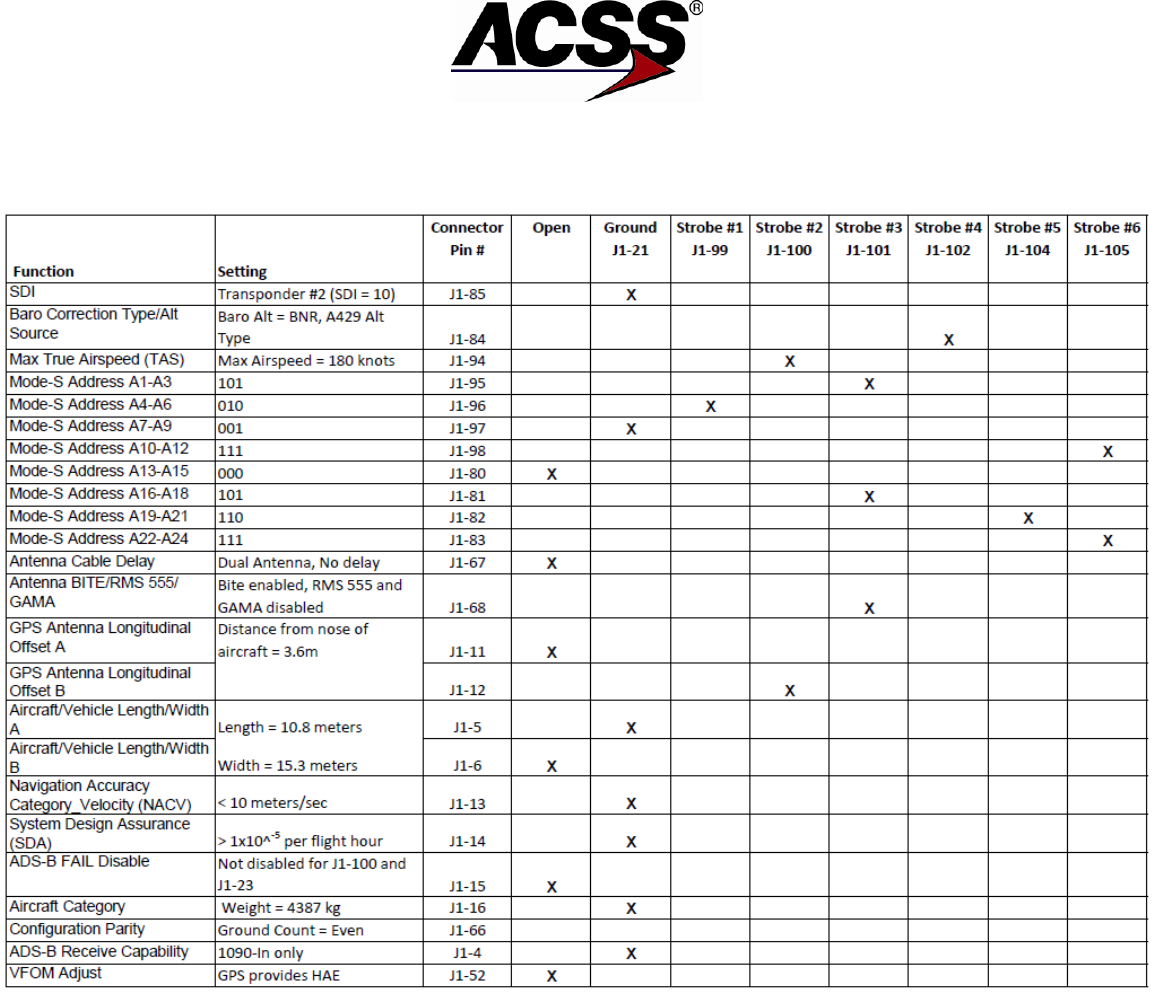
SYSTEM DESCRIPTION AND INSTALLATION MANUAL
NXT-600 Mode S/ADS-B Transponder/Part No. 9006000
Table 4-21: Example of Configuration Encoding (N6754H)
4-28
26 Mar 2014 34-52-13 Pub. No. 8600600-001, Revision 001
Use or disclosure of information on this page is subject to the restrictions in the proprietary notice of this document.
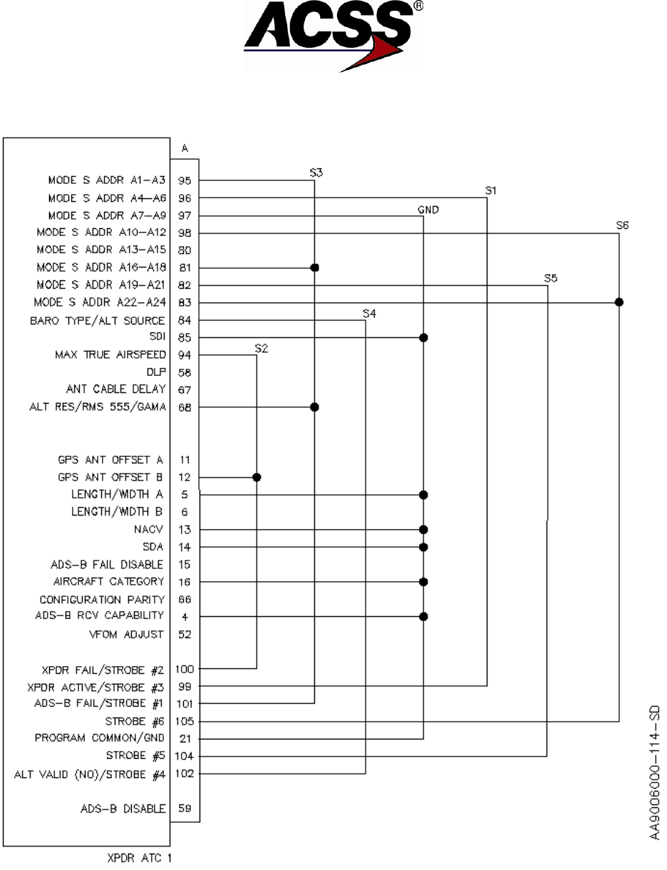
SYSTEM DESCRIPTION AND INSTALLATION MANUAL
NXT-600 Mode S/ADS-B Transponder/Part No. 9006000
Figure 4-1: Example of Configuration Encoding Pinout (N6754H)
Pub. No. 8600600-001, Revision 001 34-52-13 4-29
26 Mar 2014
Use or disclosure of information on this page is subject to the restrictions in the proprietary notice of this document.

SYSTEM DESCRIPTION AND INSTALLATION MANUAL
NXT-600 Mode S/ADS-B Transponder/Part No. 9006000
Blank Page
4-30
26 Mar 2014 34-52-13 Pub. No. 8600600-001, Revision 001
Use or disclosure of information on this page is subject to the restrictions in the proprietary notice of this document.
SYSTEM DESCRIPTION AND INSTALLATION MANUAL
NXT-600 Mode S/ADS-B Transponder/Part No. 9006000
ADJUSTMENT/TEST
1. General
The procedures that follow are designed to check for proper operation and satisfactory installation
of the NXT-600 Transponder System while the aircraft is on the ground. These procedures
describe a single and/or a dual Mode S transponder installation. For dual transponder
installations, the same procedure can be used to check each transponder individually.
2. Equipment and Materials
Equipment and materials required to test and checkout the transponder are given in Table 5-1.
Table 5-1: Equipment and Materials
Equipment
Description
Source
Digital Multimeter
Fluke Model 29 Digital Multimeter
John Fluke Mfg Co Inc, Everett,
WA
Transponder Ramp Tester
IFR-601 Transponder Test Set
Aeroflex Inc., Plainview, NY
IFR 6000 ATC/TCAS/DME Test
Set
Aeroflex Inc., Plainview, NY
TB-2100 ATC/DME Test Set
Tel-Instrument Electronics Corp,
Carlstadt, NJ
APM-424 Transponder Test Set
JcAir Test Systems, New Century, KS
Air Data Test Set
Pilot/static test set
Any Commercial Source
NOTE: Equivalent alternatives are permitted for equipment in this list.
3. Initial Harness Checkout (New Installations Only)
A. Transponder and Control Panel Harness Checkout
Refer to the applicable transponder and control unit interconnect diagrams to do
continuity measurements and to ensure confidence in wiring for these units.
B. LRU Pre-installation Power Check
Before doing any operational tests, a power-on check is recommended to reduce the
possibility of damage to newly installed system components, due to miswired power
leads.
(1) Make sure all transponder components are removed from their mounting tray or
that their aircraft mating connector(s) are disconnected.
(2) Connect external power to aircraft.
(3) Close all transponder 28 V dc circuit breakers, if applicable, and check for 28 V
dc at the appropriate LRU mating connector pins. Refer to the applicable
interconnect diagrams for LRU pin numbers.
Pub. No. 8600600-001, Revision 001 34-52-13 5-1
26 Mar 2014
Use or disclosure of information on this page is subject to the restrictions in the proprietary notice of this document.

SYSTEM DESCRIPTION AND INSTALLATION MANUAL
NXT-600 Mode S/ADS-B Transponder/Part No. 9006000
(4) If power is misapplied on any connector pin, open the circuit breaker and rework
miswired harness.
(5) Remove aircraft power.
C. Initial System Installation Operational Test
The initial checkout of a newly installed system should start with a system self-test and
then be followed by a ramp test. The system self-test procedures are referenced in
paragraph 4. The ramp tests should include an altitude reporting on/off test, a power and
frequency test, an ATCRBS-only test, and a test to check the 4096 codes. For ADS-B
installations ensure an ADS- B capable ramp tester is used to test the ADS-B registers.
Refer to the applicable transponder ramp tester operation manual for procedures to do
these tests.
4. Transponder Self-Test
A. With all power off, reinstall the transponder in its mounting tray. Make sure the control
panel is also installed.
B. Apply aircraft power and close all applicable transponder circuit breakers.
C. Set control unit mode switch to STANDBY mode.
D. Press and release the PUSH TO TEST button on the transponder front panel. The test
sequence that follows should occur.
● All transponder front panel annunciators come on for a 3-second lamp test.
● If the transponder is operational, the green XPDR PASS annunciator comes on for a
10-second display period and then goes off.
● If the transponder is not operational, one or more of the red fault annunciators comes
on for a 10-second display period.
E. Make sure that transponder is operational. If failures are indicated, refer to the FAULT
ISOLATION section of this manual; otherwise, proceed.
F. For a dual Mode S installation, repeat steps D. and E. for second transponder. Make sure
the second transponder is selected on the control panel before repeating test.
NOTE: When the aircraft is on the ground, the lamps on the front panel of the
transponder are active and represent the current status of subsystems. While
in the air, all intermittent and hard failures are logged in the internal fault
memory and are displayed for that flight leg when fault data is reviewed on the
ground. This means while in the air, if an antenna fails for a short time and
recovers for an unknown reason that particular flight leg results in an antenna
fault that displays on the front lamps of the transponder. The exception is the
off-side transponder (stand-by) does not run antenna BITE on the top/bottom
antenna, so antenna failures are not recorded in the fault log of the off-side
(stand-by) transponder.
5-2
26 Mar 2014 34-52-13 Pub. No. 8600600-001, Revision 001
Use or disclosure of information on this page is subject to the restrictions in the proprietary notice of this document.

SYSTEM DESCRIPTION AND INSTALLATION MANUAL
NXT-600 Mode S/ADS-B Transponder/Part No. 9006000
5. Return-To-Service
Any time a transponder LRU has been removed and replaced following repair or maintenance, a
return-to-service test is required. Refer to Section 7, MAINTENANCE PRACTICES, for
applicable procedures.
Pub. No. 8600600-001, Revision 001 34-52-13 5-3
26 Mar 2014
Use or disclosure of information on this page is subject to the restrictions in the proprietary notice of this document.

SYSTEM DESCRIPTION AND INSTALLATION MANUAL
NXT-600 Mode S/ADS-B Transponder/Part No. 9006000
Blank Page
5-4
26 Mar 2014 34-52-13 Pub. No. 8600600-001, Revision 001
Use or disclosure of information on this page is subject to the restrictions in the proprietary notice of this document.

SYSTEM DESCRIPTION AND INSTALLATION MANUAL
NXT-600 Mode S/ADS-B Transponder/Part No. 9006000
FAULT ISOLATION
1. General
The NXT-600 Mode S/ADS-B Transponder has a Built-In Test function that contains a continuous
performance monitor and self-test monitor. The continuous performance monitor function
monitors critical system parameters and records faults found during normal operation.
The self-test monitor function is activated upon command from the system controller, external
discrete input, front test panel switch, maintenance computer, or a power-on cold start. The self-
test function will annunciate active failures of the system, and provide historical data from
previous flight legs.
The faults recorded by the performance monitor or self-test monitor are contained in a non-
volatile fault log, which may be downloaded to a file using the WebEDDIT software tool.
Additionally, the NXT-600 Transponder has self-test capability that is activated and displayed on
its front panel. This self-test function also indicates subsystem failures. For instance, if a control
panel failure is annunciated, that specific unit can be replaced instead of unnecessarily removing
a the NXT-600 Transponder.
2. Equipment
None.
3. Monitor Fault Logging
Faults detected by either the performance monitor or self-test monitor are logged in nonvolatile
memory, and may be extracted from the transponder by maintenance personnel by downloading
it to the WebEDDIT software tool.
4. Power-On Test
Power-On Test is always executed on a cold start, on ground only. When the transponder is
powered on, all lamps on a front panel lit up (XPDR P/F- Green, all others - Red). After Power-On
Test finishes successfully, all lamps turn off. If there is any failure diagnosed during Power-On
Test, lamps indicate the failure for 10 seconds per Table 6-1.
5. Self-Test Monitor
The self-test monitor function is activated upon command from the system controller, external
discrete input, front panel test switch, maintenance computer, or a power-on cold start.
There are no specific monitors exercised during self-test. The self-test function will annunciate
active failures of the system, and provide recorded data from previous flight legs.
Pub. No. 8600600-001, Revision 001 34-52-13 6-1
26 Mar 2014
Use or disclosure of information on this page is subject to the restrictions in the proprietary notice of this document.
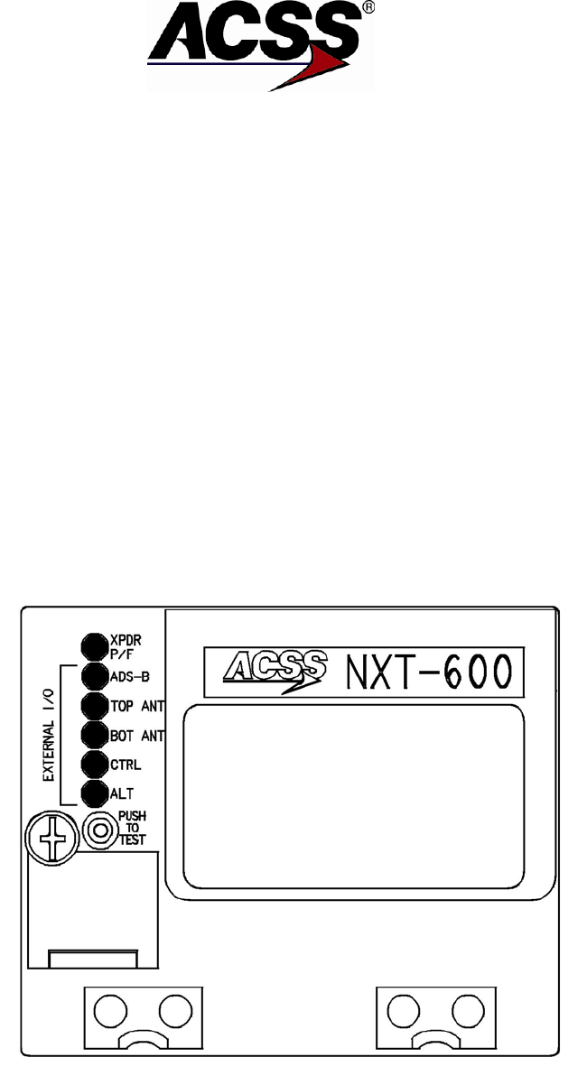
SYSTEM DESCRIPTION AND INSTALLATION MANUAL
NXT-600 Mode S/ADS-B Transponder/Part No. 9006000
Functions that are monitored are as follows:
● Memory integrity
● Hardware, Firmware, and Software health and integrity
● ARINC 429 Transmitter and Receiver
● Discrete I/O
● Weight-On-Wheels Discrete Monitor
● RF Transmitter and Receiver
While on the ground, the status of the front panel test switch (Figure 6-1), is checked every 200
milliseconds by software. Front panel lamps do not come on if the transponder is in the air mode.
Upon sensing a single momentary switch activation, all front panel lamps come on for a period of
2 to 3 seconds to test lamp function. The next available performance monitor results are then
used to drive the front panel lamps for the next 10 seconds.
Table 6-1 indicates the interface or LRU that is invalid when the indicated lamp is lit, and possible
corrective actions to be taken to solve the problem.
Figure 6-1: NXT-600 Transponder Front Panel
6-2
26 Mar 2014 34-52-13 Pub. No. 8600600-001, Revision 001
Use or disclosure of information on this page is subject to the restrictions in the proprietary notice of this document.

SYSTEM DESCRIPTION AND INSTALLATION MANUAL
NXT-600 Mode S/ADS-B Transponder/Part No. 9006000
Table 6-1: Interface/LRU Possible Corrective Actions
Lamp
Failure
Possible Action
XPDR P/F
A green lamp indicates no failures.
A red lamp indicates the transponder's
internal performance monitors and BITE
circuitry has detected a failure.
None
Remove and replace transponder
(See note).
ADS-B
This lamp is used to annunciate that the
GPS position input that is required by the
ADS-B OUT function is failed or
unavailable.
Check GPS position source.
TOP ANT
Top antenna, or cabling and connectors to
top antenna, has failed by indicating a
resistance to ground >500 ohms.
Verify antenna cabling and
connections (after removing
transponder). Repair cabling or
replace antenna as required.
BOT ANT
Bottom antenna, or cabling and connectors
to bottom antenna, has failed by indicating
a resistance to ground >500 ohms.
Verify antenna cabling and
connections (after removing
transponder). Repair cabling or
replace antenna as required.
CTRL
Control panel has failed.
Select correct control panel source.
Verify control panel cabling and signal
presence. Replace control panel, if
necessary.
ALT
The transponder systems ARINC 429 or
575 digital altitude sources SSM may be
indicating FAIL WARNING or the bus may
be inactive.
Verify altitude source is selected.
Check altitude source.
NOTE: If the Mode S address is all 1's or all 0's, the XPDR P/F lamp will indicate red.
Pub. No. 8600600-001, Revision 001 34-52-13 6-3
26 Mar 2014
Use or disclosure of information on this page is subject to the restrictions in the proprietary notice of this document.

SYSTEM DESCRIPTION AND INSTALLATION MANUAL
NXT-600 Mode S/ADS-B Transponder/Part No. 9006000
A. Self-Test Initiation from Test Button
The transponder front panel test button initiates a self-test and retrieves data from past
flight legs for display on the panel. The self-test monitor has the following requirements
when initiated by the front panel test button.
(1) The self-test monitor is initiated when the test button is pushed when the aircraft
is on the ground.
(2) The self-test monitor completes the self-test sequence once initiated, even if the
test button is released. All front panel lamps come on and remain on while the
self-test sequence is running.
(3) After the self-test sequence has completed, the transponder displays the results
of the test on the front panel lamps for approximately 10 seconds. Any faults that
become active during this time are displayed.
(4) If the button is released and then pushed after the self-test sequence has been
completed, but before the 10 seconds have timed out, the transponder turns on
all lamps for approximately 1 second, then displays the results for all failures
(whether currently active or not) for the current flight leg.
(5) Continuing to push and release the test button displays contents for previous
flight legs, as described in step (4), for up to 10 flight legs, or the maximum
number of stored flight legs (if less than 10). If the button is pushed on the tenth
or last flight leg, the lamps flash at a 5 Hz rate for 3 seconds. The flight leg
display mode then terminates.
(6) If 10 seconds expire without the test button being pushed, the front panel lamps
go off and the self-test display mode or the flight leg display mode terminates.
(7) The self-test monitor cannot be initiated if the aircraft is in the air.
B. Front Panel Lamp Display
The front panel lamp display annunciates failures in the transponder unit or failures of
systems that are connected to the transponder as follows.
(1) Faults that are annunciated are a result of the continuous performance monitor
and the self-test monitor.
(2) Faults that are displayed as a result of self-test are combined with faults that
have been detected by the performance monitor. These faults are currently
active. Faults that were detected previously by the performance monitor and
have been cleared at the time the test is initiated are not annunciated.
(3) Faults that are displayed for the current or previous flight leg are faults detected
as a result of self-test or the performance monitor. Faults that were intermittent
are displayed.
(4) These results are only displayed following a self-test initiated by the front panel
self-test button. There is no display during or following a self-test initiated by
other means or during non self-test operation.
6-4
26 Mar 2014 34-52-13 Pub. No. 8600600-001, Revision 001
Use or disclosure of information on this page is subject to the restrictions in the proprietary notice of this document.

SYSTEM DESCRIPTION AND INSTALLATION MANUAL
NXT-600 Mode S/ADS-B Transponder/Part No. 9006000
NOTE: When the aircraft is on the ground, the lamps on the front panel of
the transponder are active and represent the current status of
subsystems. While in the air, all intermittent and hard failures are
logged in the internal fault memory and are displayed for that flight
leg when fault data is reviewed on the ground. This means while in
the air, if an antenna fails for a short time and recovers for an
unknown reason, that particular flight leg results in an antenna fault
that displays on the front lamp of the transponder. The exception is
the off-side transponder (stand-by) does not run antenna BITE on
the top/bottom antenna, so antenna failures are not recorded in the
fault log of the off-side (stand-by) transponder.
6. Continuous Performance Monitor
The continuous performance monitor function is used to monitor the system condition under
normal operation and annunciate faults as required. The function monitors circuitry internal to the
transponder and also monitors interfaces to other systems and subsystems. If a fault is detected
in either internal circuitry or external systems, the fault is recorded in an internal fault log.
Depending on the severity of the fault or the impact on system operation, the fault may also be
annunciated to the flight crew by the transponder control panel failure annunciator.
All failures are logged into non-volatile memory for later analysis by maintenance personnel. The
following functions are tested by the continuous performance monitor on a once per second cyclic
basis (except for power-on test functions):
● Flash EPROM Memory
● Calibration RAM Memory
● Hardware Watchdog Monitor
● RAM SEU Monitor
● FPGA SEU Monitor
● RAM Software CRC Monitor
● DAPS Input Monitor
● ARINC 429 TCAS Bus Monitor
● ARINC 429/575 Altitude Bus Monitor
● ARINC 429 ADLP Bus Monitor
● ARINC 429 Control Panel Bus Monitor
● ARINC 429 Maintenance Bus Monitor
● Discrete Output Monitor
● WOW Input Discrete Monitor
● Invalid Mode S Address Monitor
● Mutual Suppression Monitor
● Mode S Address Change Monitor
Pub. No. 8600600-001, Revision 001 34-52-13 6-5
26 Mar 2014
Use or disclosure of information on this page is subject to the restrictions in the proprietary notice of this document.

SYSTEM DESCRIPTION AND INSTALLATION MANUAL
NXT-600 Mode S/ADS-B Transponder/Part No. 9006000
● RF Forward Power
● Squitter Monitor
● Local Oscillator Synthesizer Monitor
● RF Receiver Monitor
● Antenna Monitor
● TCAS Dispatch Failure
● Power Supply Voltages
● Ambient Temperature Monitor
● Unexpected Cold Start
● Software Fault Monitor.
A. Fault Indications
Table 6-2 provides a list of fault indications for all failures that can be diagnosed in field.
The rest of the failures, such as power supply monitor faults or Local Oscillator fault, are
not indicated, but are recorded in internal non-volatile memory and can be accessed if
unit is returned to the factory for service. See Table 6-1 for recommended corrective
actions.
Coding used in the various table columns is as follows:
● In the transponder Front Panel Lamps column, the following letters correspond to
setting the specified lamps:
X - XPDR P/F
S - ADS-B
T - TOP ANT
B - BOT ANT.
C - CTRL
A - ALT
● Y in the Standby column indicates that Transponder will go into Standby mode
● Y in LRU Reset column indicates that Transponder will perform a Reset.
● Y in the TCAS Fail column indicates whether a failure is indicated on the TCAS
display.
● X in Discretes Column indicates “XPDR FAIL” on Control Panel
● Z in Discretes Column indicates “ADS-B FAIL” on Control Panel
6-6
26 Mar 2014 34-52-13 Pub. No. 8600600-001, Revision 001
Use or disclosure of information on this page is subject to the restrictions in the proprietary notice of this document.

SYSTEM DESCRIPTION AND INSTALLATION MANUAL
NXT-600 Mode S/ADS-B Transponder/Part No. 9006000
Table 6-2: XPDR Failure Indications
Description
Front Panel
Lamps1
Standby
TCAS
Fail
LRU
Reset
Discretes
CTRL
L350
BIT/Fault
Code
Calibration RAM Memory CRC
Fault
X
Y
Y
X
Code 70
RAM SEU Not Corrected Fault
X
Y
Y
Y
X
FPGA SEU Not Corrected Fault
X
Y
Y
Y
X
Hardware Watchdog Fault
X
Y
Y
X
RAM Software CRC Fault
X
Y
Y
X
TCAS Bus Failure
BIT 28
Code B2
ARINC 429/575 Altitude Bus #1
Class 1 Fault
A
X
BIT 25
Code 91
ARINC 429/575 Altitude Bus #2
Class 1 Fault
A
X
BIT 26
Code 92
Control Panel Port A Fault
C
Y
X
Code 82
Control Panel Port B Fault
C
Y
X
Code 83
Invalid Mode S Address Fault
X
Y
Y
X
Code F0
WOW Input Discrete Fault
X
Y
X
ADS-B System Fail with Light
Fault
S
X, Z2
BIT 29
ADS-B System Fail with No
Light Fault
S
Z3
BIT 29
Forward Power Fault Bot
antenna
X
Y
X
Code 23
Forward Power Fault Top
antenna
X
Y
X
Code 22
Forward Power Isolation Fault
Bot antenna
X
Y
X
Forward Power Isolation Fault
Top antenna
X
Y
X
Squitter Fault
X
Y
X
Top RCVR Listen Fault
X
Y
X
Top RCVR Isolate Fault
X
Y
X
Bot RCVR Listen Fault
X
Y
X
Bot RCVR Isolate Fault
X
Y
X
RF ATCRBS Receiver Fault
X
Y
X
Bot Antenna Fault
B
Pub. No. 8600600-001, Revision 001 34-52-13 6-7
26 Mar 2014
Use or disclosure of information on this page is subject to the restrictions in the proprietary notice of this document.

SYSTEM DESCRIPTION AND INSTALLATION MANUAL
NXT-600 Mode S/ADS-B Transponder/Part No. 9006000
Table 6-3: XPDR Failure Indications (cont)
Description
Front Panel
Lamps1
Standby
TCAS
Fail
LRU
Reset
Discretes
CTRL
L350
BIT/Fault
Code
Top Antenna Fault
T
TCAS Dispatch Fault Bottom
Y
X
TCAS Dispatch Fault Top
Y
X
Operational Software Fault
Y
Boot ARINC RCVR Fault
X
Y
X
Boot_ARINC_XMTR_Fault
X
Y
X
Boot_XIC_FPGA_CRC_Fault
Y5
Boot_XIC_FPGA_Load_Fault
Y
Boot_BOOT_CRC_Fault
Y
Boot_DL1_CRC_Fault
Y4
Boot_DL2_CRC_Fault
Y4
Boot_APP_CRC_Fault
Y5
Boot_Calibration_CRC_Fault
X
Y
X
Boot_RAMADDR_Fault
Y
Boot_RAMPAT_Fault
Y
Boot_ECC_Fault
Y
Boot_DLRAM_CRC_Fault
Y
Boot_Exception_Fault
Y
Boot_Image_Compatible_Fault
X
Y
X
Boot LRU Type Compare Fault
X
Y
X
Boot Discrete Input Test Fault
X
Y
X
Boot_XICFPGA_SEM_Fault
Y
Synthesizer Lock detect failure
X
Y
Y
X
Code 31
Notes:
1. If no errors corresponding to XPDR FAIL are detected, the XPDR P/F Green lamp is to be lit.
2. If Extended Squitters are disabled the XPDR FAIL discretes and ADS-B Function Fail discrete are
not activated.
3. If Extended Squitters are disabled the ADS-B Function Fail discrete is not activated.
4. This fault may or may not cause a reset depending on a Request for Data Load.
5. If unable to force a data load, LRU reset is triggered.
6-8
26 Mar 2014 34-52-13 Pub. No. 8600600-001, Revision 001
Use or disclosure of information on this page is subject to the restrictions in the proprietary notice of this document.

SYSTEM DESCRIPTION AND INSTALLATION MANUAL
NXT-600 Mode S/ADS-B Transponder/Part No. 9006000
MAINTENANCE PRACTICES
1. General
This section provides instructions for removing, reinstalling, and adjusting each Line Replaceable
Unit (LRU) of the NXT-600 Mode S/ADS-B Transponder that has been previously installed by the
aircraft manufacturer or completion center.
CAUTION: SHOULD ANY INSTALLATION CRITICAL CASES ARISE WITH THE
REINSTALLATION OF ANY UNIT, INSTRUCTIONS MUST BE
FOLLOWED 100 PERCENT.
CAUTION: WHEN REMOVING OR INSTALLING ANY LRU, PREPARE THE
AIRCRAFT FOR SAFE GROUND MAINTENANCE. OPEN AND TAG
ALL APPLICABLE SYSTEM CIRCUIT BREAKERS.
2. Equipment and Materials
Refer to the Aircraft Maintenance Manual (AMM) for materials required to install necessary
components.
NOTE: No special equipment or materials other than those commonly used by line
maintenance technicians are required to remove and install the units. Do not over
tighten the mounting screws and hold-down knobs. Where torque values are not
given, it is acceptable to hand tighten the mounting screws and finger tighten the
equipment hold-down knobs.
3. Procedure for the NXT-600 Mode S/ADS-B Transponder
A. Removal and Installation Procedure
(1) Remove the NXT-600 Transponder.
(a) Loosen the mounting tray hold-down knobs.
(b) Slowly pull on the transponder’s handle to separate the unit from its
mounting tray connector. The transponder is now free to be removed
from its mounting tray.
(c) Place electrostatic protective cover on the transponder’s connector.
(2) Reinstall the NXT-600 Transponder.
(a) Remove the electrostatic protective cover from the transponder’s
connector.
(b) Slide the transponder into its mounting tray.
Pub. No. 8600600-001, Revision 001 34-52-13 7-1
26 Mar 2014
Use or disclosure of information on this page is subject to the restrictions in the proprietary notice of this document.

SYSTEM DESCRIPTION AND INSTALLATION MANUAL
NXT-600 Mode S/ADS-B Transponder/Part No. 9006000
CAUTION: DO NOT FORCE FIT. IF MATING IS DIFFICULT, REMOVE
THE UNIT AND EXAMINE THE CONNECTORS FOR
CONTACTS THAT ARE BENT OR OUT OF ALIGNMENT.
ALSO CHECK THE ALIGNMENT OF THE CONNECTORS’
POLARIZATION KEYS AND POSTS.
(c) Carefully apply firm pressure until the transponder connector mates with
the tray connector.
(d) Tighten mounting tray hold-down knobs to make sure that the connectors
are fully engaged.
B. Adjustment Procedure
Not Applicable.
C. Repair Procedure
Not Applicable.
D. Return to Service Procedures
For installations using serial data bus (ARINC 429) or analog altitude data, do the
transponder self-test procedures referenced in Section 5, Adjustment/Test. After the
transponder passes these tests, the appropriate logbook entries can be made and the
unit is ready for use.
4. Procedure for the Omnidirectional Antenna
A. Removal and Installation Procedure
(1) Prior to removing the Mode S antenna, put the transponder into stand-by mode
or pull and collar the ATC circuit breaker before commencing with maintenance.
(2) Remove the omnidirectional antenna.
(a) If applicable, use a phenolic scraper to remove aerodynamic sealant
around periphery of antenna baseplate.
(b) If applicable, remove sealant from antenna mounting screw holes.
(c) Remove retaining screws used to secure antenna to aircraft fuselage.
(d) Carefully pull antenna from fuselage.
(e) Disconnect the coaxial cable connector from the antenna.
(f) Put protective covers on the aircraft coaxial cable connector and the
antenna connector.
7-2
26 Mar 2014 34-52-13 Pub. No. 8600600-001, Revision 001
Use or disclosure of information on this page is subject to the restrictions in the proprietary notice of this document.

SYSTEM DESCRIPTION AND INSTALLATION MANUAL
NXT-600 Mode S/ADS-B Transponder/Part No. 9006000
(3) Reinstall the omnidirectional antenna.
(a) If applicable, remove any existing aerodynamic sealant from antenna
mounting surface and clean antenna mounting area.
(b) Remove and clean sealant from baseplate and baseplate cutout.
(c) Remove protective covers from antenna and coaxial cable connectors.
(d) Examine antenna and coaxial cable connectors to make sure that they
are clean and secure.
(e) Connect aircraft coaxial cable to antenna connector.
(f) Position the antenna on the fuselage mounting surface and secure the
antenna with the appropriate screws.
(g) Apply an aerodynamic sealant around the periphery of the antenna
baseplate.
B. Adjustment Procedure
Not Applicable
C. Repair Procedure
Most omnidirectional antennas are non-repairable. If the antenna is damaged or faulty, it
must be replaced with a new antenna.
D. Return to Service
Do the transponder Return to Service Test Procedures referenced in paragraph 3.D. of
this section.
5. Procedure for the Control Panel
A. Removal and Installation Procedure
(1) Remove the control panel.
(a) Disengage Dzus fasteners on control panel.
(b) Pull control panel out of aircraft mounting location and disconnect aircraft
cable connectors. Control panel is now free to be removed from aircraft.
(c) Put electrostatic protective covers on control panel and aircraft mating
electrical connectors.
(2) Reinstall the control panel.
(a) Remove protective covers from control panel and aircraft mating
connectors.
Pub. No. 8600600-001, Revision 001 34-52-13 7-3
26 Mar 2014
Use or disclosure of information on this page is subject to the restrictions in the proprietary notice of this document.

SYSTEM DESCRIPTION AND INSTALLATION MANUAL
NXT-600 Mode S/ADS-B Transponder/Part No. 9006000
(b) Connect aircraft cables to control panel connectors.
(c) Insert control panel into mounting location.
(d) Engage Dzus fasteners on the control panel to secure it to aircraft
structure.
B. Adjustment Procedure
Not Applicable
C. Repair Procedure
Any repair procedures should be in accordance with manufacturer's repair instructions.
D. Return to Service Procedures
Do the transponder Return to Service Test Procedures referenced in paragraph 3.D. of
this section.
6. Instruction for Continued Airworthiness, 14 CFR Part 25.1529
Maintenance requirements and instructions for Continued Airworthiness of the NXT-600 Mode
S/ADS-B Transponder components are contained in the paragraphs that follow:
Installation of the transponder on an aircraft by Supplemental Type Certificate or Form 337
obligates the aircraft operator to include the maintenance information supplied by this manual in
the operator's Aircraft Maintenance Manual and the operator's Aircraft Scheduled Maintenance
Program.
The Airworthiness Limitations Section is FAA approved and specifies maintenance required
under 14 CFR Part 43.16 and 14 CFR Part 91.403 of the Federal Aviation Regulations, unless an
alternative program has been FAA approved.
A. Installation and maintenance information for the transponder is contained in this manual.
Refer to the Sections System Description, Mechanical Installation, Electrical Installation,
Adjustment/Test and Maintenance Practice; sub-section Removal and Installation Procedure,
Inspection/Check, Cleaning/Painting, etc.
B. There are no special tools required for the removal and installation of the NXT-600
Transponder other than commonly used Line Maintenance support equipment.
C. Required information on the NXT-600 interfaces is detailed in Section 1 System Description
and Section 4 Loading/Gradient Specifications.
D. Basic control and operating information are included in this installation manual. Refer to
Section 1 System Description sub-sections Component Descriptions and Functional
Description and Operation.
7-4
26 Mar 2014 34-52-13 Pub. No. 8600600-001, Revision 001
Use or disclosure of information on this page is subject to the restrictions in the proprietary notice of this document.

SYSTEM DESCRIPTION AND INSTALLATION MANUAL
NXT-600 Mode S/ADS-B Transponder/Part No. 9006000
E. Line Replaceable Unit (LRU) part numbers and other necessary part numbers contained in
this manual should be placed into the aircraft operator's appropriate aircraft Illustrated Parts
Catalog (IPC).
F. Wiring diagram information contained in this manual should be placed into the aircraft
operator's appropriate aircraft Wiring Diagram Manuals. Refer to Figure 2-1 NXT-600 Mode
S/ADS-B Transponder Outline and Installation Diagram.
G. The transponder is considered an on-condition unit and no additional maintenance is required
other than a check for security and operation at normal inspection intervals.
H. If a system component is inoperative, remove unit, secure cables and wiring, collar applicable
switches and circuit breakers, and placard them inoperative. Revise equipment list and
weight and balance as applicable prior to flight and make a log book entry that unit was
removed (refer to 14 CFR Part 91.213 or the aircraft's Minimum Equipment List [MEL]).
I. The transponder system LRUs can be repaired only at a factory-authorized repair center or
an appropriately rated 14 CFR Part 145 repair station.
J. Once repaired, reinstall the LRU in the aircraft in accordance with the original Form 337
approved data or instructions in this manual. Do a Return to Service test of the system and
approve it for return to service with a log book entry in accordance with the requirements
specified in 14 CFR Part 43.9.
K. Scheduled Maintenance Program tasks to be added to the aircraft operator's appropriate
aircraft maintenance program are as follows:
(1) Recommended periodic scheduled servicing tasks: none required.
(2) Recommended periodic inspections are as follows.
● The NXT-600 Mode S/ADS-B Transponder has tests and inspections that are
required by 14 CFR Part 91.413 to be completed every 24 calendar months.
● The ATC antennas used with the NXT-600 Mode S/ADS-B Transponder
should be removed and the underlying structure inspected for deterioration
and corrosion every 60 months or 12,000 hours, whichever occurs first.
(3) Recommended periodic scheduled preventative maintenance tests (tests to
determine system condition and/or latent failures).
● The NXT-600 Mode S/ADS-B Transponder is designed to detect its own
failures as well as failures external to the transponder itself. This BIT is
continuously being executed on a periodic basis. Refer to Section Fault
Isolation.
● No formal periodic maintenance is required for the transponder or the control
panel other than the 24 calendar month re-certification test required by 14
CFR Part 91.413.
L. If there are changes to the Instructions for Continued Airworthiness, the installation manual
will be revised accordingly. When document revisions are approved, the ACSS Customer
Services extranet website is automatically updated. The extranet site then notifies the
affected customers automatically by email, and on next login of the documentation change.
This process is documented in ACSS INS-13.8-1, Distributing Publications via the ACSS
Customer Services Extranet.
Pub. No. 8600600-001, Revision 001 34-52-13 7-5
26 Mar 2014
Use or disclosure of information on this page is subject to the restrictions in the proprietary notice of this document.

SYSTEM DESCRIPTION AND INSTALLATION MANUAL
NXT-600 Mode S/ADS-B Transponder/Part No. 9006000
Blank Page
7-6
26 Mar 2014 34-52-13 Pub. No. 8600600-001, Revision 001
Use or disclosure of information on this page is subject to the restrictions in the proprietary notice of this document.

SYSTEM DESCRIPTION AND INSTALLATION MANUAL
NXT-600 Mode S/ADS-B Transponder/Part No. 9006000
INSPECTION/CHECK
1. General
The visual check procedures that follow are recommended for the transponder and associated
LRUs after they have been installed in the aircraft.
2. Procedure
CAUTION: MAKE SURE THAT THE TRANSPONDER SYSTEM CIRCUIT BREAKERS
ARE OPEN BEFORE DOING ANY OF THE PROCEDURES THAT FOLLOW.
A. Check Transponder
(1) Visually examine all external surfaces for possible damage. Check dust cover
and external connectors for dust, corrosion, or damage.
(2) Check external parts for loose or damaged hardware.
(3) Make visual check of wiring and connectors for damage.
B. Check Antenna
(1) Visually examine all external surfaces for possible damage.
(2) Check coaxial cables for breaks, burned areas, and damaged insulation.
C. Check Control Panel
(1) Visually examine all external surfaces for possible damage.
(2) Check external parts (connectors, control knobs, annunciators) for looseness or
damage.
(3) Check controls for smooth, positive action.
(4) Check that control panel is securely mounted (Dzus fasteners properly engaged).
Pub. No. 8600600-001, Revision 001 34-52-13 8-1
26 Mar 2014
Use or disclosure of information on this page is subject to the restrictions in the proprietary notice of this document.

SYSTEM DESCRIPTION AND INSTALLATION MANUAL
NXT-600 Mode S/ADS-B Transponder/Part No. 9006000
Blank Page
8-2
26 Mar 2014 34-52-13 Pub. No. 8600600-001, Revision 001
Use or disclosure of information on this page is subject to the restrictions in the proprietary notice of this document.

SYSTEM DESCRIPTION AND INSTALLATION MANUAL
NXT-600 Mode S/ADS-B Transponder/Part No. 9006000
CLEANING/PAINTING
1. General
While the NXT-600 System is installed in the aircraft, cleaning is limited to the procedures given
below. Painting and more extensive cleaning should be done during maintenance when the
LRUs can be disassembled. Detailed instructions are presented in each applicable component-
level maintenance manual.
2. Equipment and Materials
Refer to Table 9-1 for equipment and materials necessary to clean the transponder and
associated LRUs.
WARNING: KNOW THE HAZARD CODE AND GET THE NECESSARY PROTECTION
BEFORE USING A MATERIAL. REFER TO THE PAGE ABOUT HAZARD
CODES FOR MATERIALS IN THE FRONT OF THIS MANUAL.
Table 9-1: Equipment and Materials
Name
Description
Source
60-086-76
Lint free cloth — Bluewipes, No.
TX512
Texwipe Co, Upper Saddle
River, NJ
Cleaning Brush
Soft, natural-bristle (camel's hair)
Optional source
11-1 15-78
HAZARD CODE 130D
Solvent, alcohol, ethanol,
denatured (O-E-760, Type lll)
Optional source
Glass Cleaner
Ammoniated
Optional source
Lens Tissue
Non-linting
Optional source
Air Supply
Air ionizing nozzle gun
attachment for compressed air
(20 psi)
Optional source
Abrasive Paper No. 600, nonconductive abrasive
Optional source
NOTE: Equivalent alternatives are permitted for equipment and materials in this list.
Pub. No. 8600600-001, Revision 001 34-52-13 9-1
26 Mar 2014
Use or disclosure of information on this page is subject to the restrictions in the proprietary notice of this document.

SYSTEM DESCRIPTION AND INSTALLATION MANUAL
NXT-600 Mode S/ADS-B Transponder/Part No. 9006000
3. Cleaning
CAUTION: IF YOU CLEAN ELECTROSTATIC SENSITIVE COMPONENTS WITH
PRESSURIZED AIR, MAKE SURE THE HOSE HAS AN AIR IONIZING
NOZZLE OR GUN. AN ELECTROSTATIC CHARGE CAN CAUSE DAMAGE
TO THE LRU COMPONENT PARTS IF THE NOZZLE OR GUN ATTACHMENT
IS NOT USED.
A. Clean Transponder and Mounting Tray
(1) Loosen hold-down clamps and pull transponder out of mounting tray.
(2) Clean mounting tray with cloth or brush dampened in solvent; dry with cloth or
compressed air.
(3) Clean all dust and foreign matter from front panel and air vents on bottom and
top of transponder using either cloth or brush dampened in solvent; dry with cloth
or compressed air.
B. Clean Antenna
Use cloth or brush dampened in solvent to clean; dry with cloth or compressed air.
C. Clean Control Panel
(1) Clean dust and foreign matter from connectors with cloth or brush dampened in
solvent. Dry with cloth or compressed air.
(2) Clean front of control panel with mild glass cleaner and soft cotton cloth.
4. Painting
Except for minor retouching, painting should be done after equipment has been removed from the
aircraft or during maintenance.
9-2
26 Mar 2014 34-52-13 Pub. No. 8600600-001, Revision 001
Use or disclosure of information on this page is subject to the restrictions in the proprietary notice of this document.

SYSTEM DESCRIPTION AND INSTALLATION MANUAL
NXT-600 Mode S/ADS-B Transponder/Part No. 9006000
REPAIRS
1. General
Major repairs to the NXT-600 System components are made only during maintenance when the
equipment is removed from the aircraft. Detailed instructions for repair and adjustment of each of
the repairable LRUs are presented in the applicable component maintenance manuals given
below.
Table 10-1: ACSS Component Maintenance Manual Reference
LRU
ACSS Component Maintenance
Manual Pub. No.
ATA Number
NXT-600 Mode S/ADS-B Transponder
Part No. 9006000-55YYY
8009103-001
34-52-14
Control Panel
Part No. 4052190-902, -904, -906, -908
15-3841-01
34-43-01
Control Panel
Part No. 4052190-903, -905, -907, -909
15-3841-03
34-43-05
Pub. No. 8600600-001, Revision 001 34-52-13 10-1
26 Mar 2014
Use or disclosure of information on this page is subject to the restrictions in the proprietary notice of this document.

SYSTEM DESCRIPTION AND INSTALLATION MANUAL
NXT-600 Mode S/ADS-B Transponder/Part No. 9006000
Blank Page
10-2
26 Mar 2014 34-52-13 Pub. No. 8600600-001, Revision 001
Use or disclosure of information on this page is subject to the restrictions in the proprietary notice of this document.