AwarePoint BLEB BLEB, BLEBD User Manual BLEX Manual
AwarePoint Corporation BLEB, BLEBD BLEX Manual
user manual

System Manager User Guide
System Manager 2.0
March 01, 2017

!
"
#$"%&""
""'"$""(##)"*
)++,
-!+.*/0"#
*"&1 "
!2"!"
""*
)++,
-!)"$""$"
"$""$"*
)++,-!
+.*/#"%)++%33
40"#*""%"%"
$"43!2"3
3"&$""3&
4*
)++,
-!4"%%""$""
354""43$"
+67-"8
+62*9
(## 7:-,
!0# ;</.:
(## 7:-,
!0# ;</.:
(## 7:-,
!0# ;</.:
(## 7:-,!
0# ;</.:
(##)"*"&1
""2
"
"
0""
*
#$"%&""
""'"$""(##)"*
-!+.*/0"#
,
%)++
*"&1 "
!2"!"
""*
-!)"$""$"
"$""$"*
+.*/#"%)++%33
40"#*""%"%"
$"43!2"3
3"&$""3&
-!4"%%""$""
354""43$"
$"=4"333*
+67-"8
+62*9
!0# ;</.:
,
!0# ;</.:
,
!0# ;</.:
,
0# ;</.:
,
"
*
#$"%&""
%)++
*"&1 "
-!)"$""$"
"$""$"*
+.*/#"%)++%33
40"#*""%"%"
$"43!2"3
!
3"&$""3&
-!4"%%""$""
$"=4"333*
2
System Manager User Guide |
System Manager 2.0
2 Introduction
System Manager is a browser-based software application that provides the user
interface (UI) to the Awarepoint Appliance. Using System Manager, you can manage
assets and network devices on the Awarepoint network, manage regions on maps, and
conduct accuracy and certification tests.
Clients should NEVER be given access to System Manager.
The Awarepoint Real-Time Location System is configured by System Manager. It can
be used online when connected to a facility’s local area network (LAN) or offline when
there is limited or no LAN access.
2.1 Accessing System Manager
System Manager is accessed through a web browser.
Currently, the only supported web browser is the latest version of Google Chrome.
While other web browsers may work, their use is not currently supported.
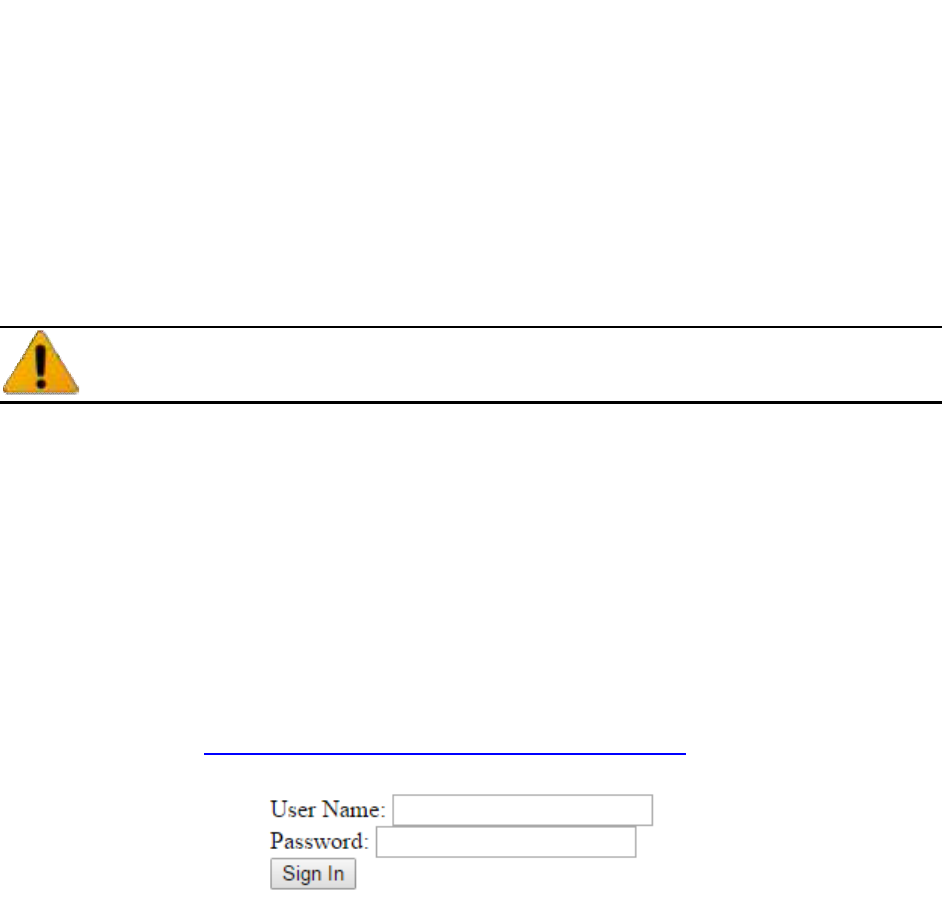
1. Navigate to https://aps.ah.awarepoint.com/awp-auth/login
Figure 1 System Manager Web Login
2. Enter your username and password and click Sign In.
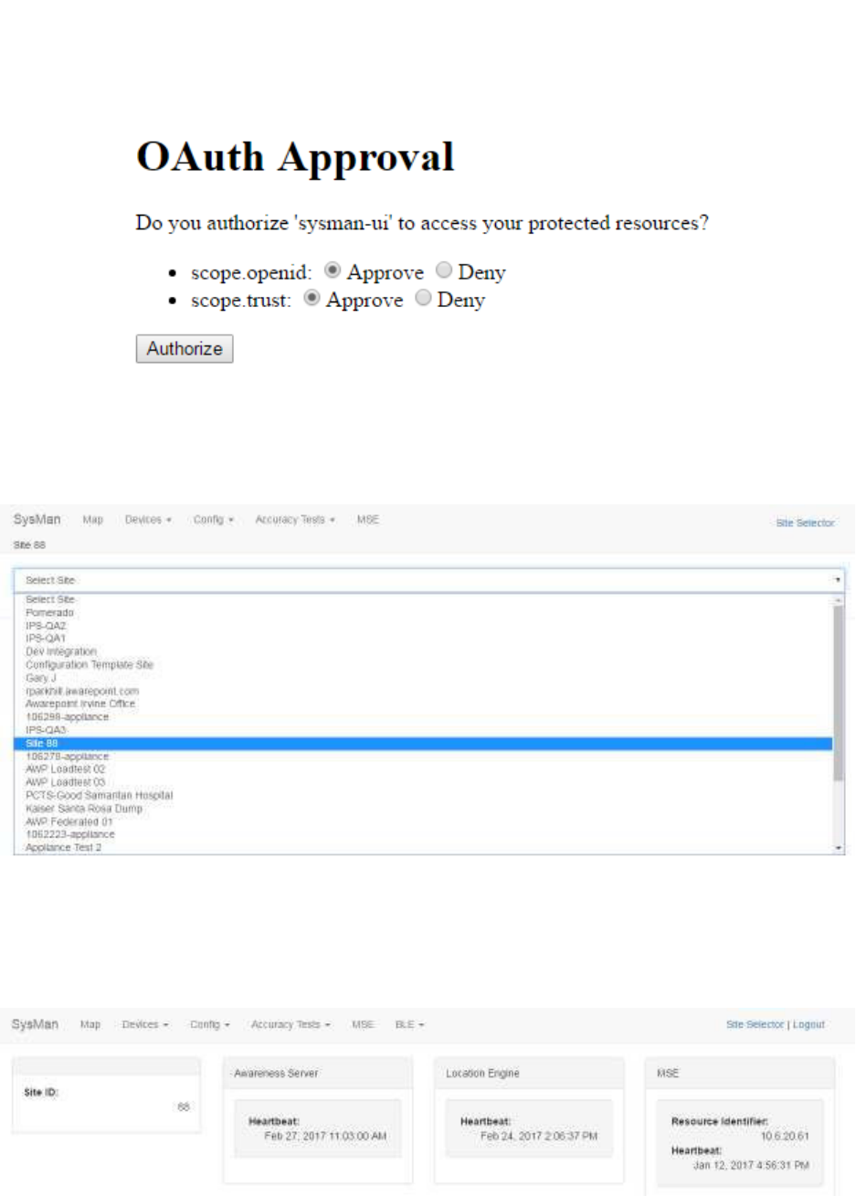
3. If asked for OAuth Approval, select the radio buttons to Approve and click
Authorize.
3
System Manager User Guide |
System Manager 2.0
Figure 2 System Manager OAuth Approval Screen
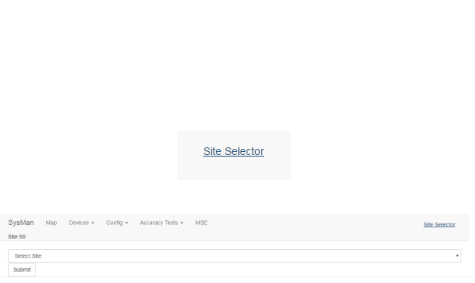
4. Select the site from the drop-down list.
Figure 3 System Manager Site Selection
The Awarepoint System Manager home screen displays for the selected site.
Figure 4 System Manager Home
4
System Manager User Guide |
System Manager 2.0
2.2 SysMan Tab
Clicking this tab returns you to the Home dashboard of System Manager. From this
screen you can log out of System Manager or choose the option to work offline and
upload any changes later.
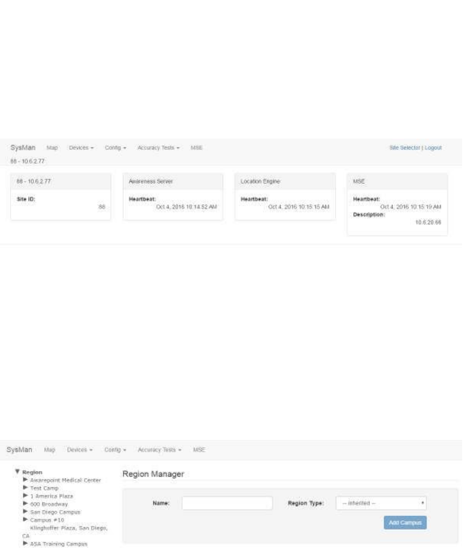
Figure 5 SysMan Tab – Home Dashboard
From this tab you can:
• View network and server information
• View information on devices on the Awarepoint network
• View information on currently active devices on the network
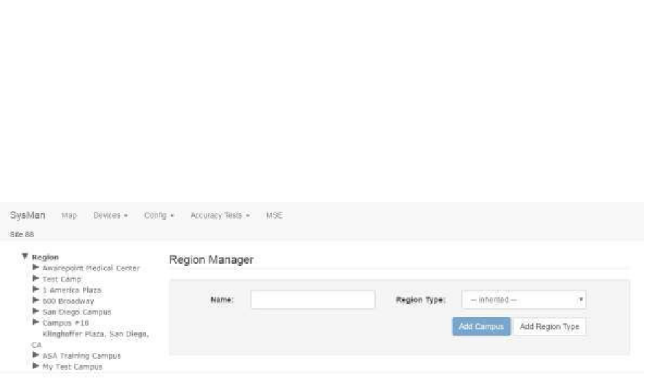
2.3 Map Tab
Clicking this tab brings you to the Region Manager screen.
Figure 6 Map Tab – Region Manager Screen
From this tab you can:
• View current maps for all defined regions, campuses, buildings, and floors
• Add a new campus, building, or floor
• Delete a campus, building, or floor
5
System Manager User Guide |
System Manager 2.0
• Import a map for a floor
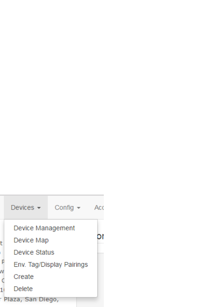
2.4 Devices Tab
This tab provides five options:
• Device Management
• Device Map
• Device Status
• Env. Tag/Display Pairings
• Create
• Delete
From this tab you can:
• Manage current BLE Tags and BLE Beacons in the system, including updating or
changing device configuration and firmware
• View and place environmental devices on a map
• View the status of a device (Tag or Beacon)
• View and manage environmental tags and display pairings
• Create new devices in the system
• Delete devices from the system
6
System Manager User Guide |
System Manager 2.0
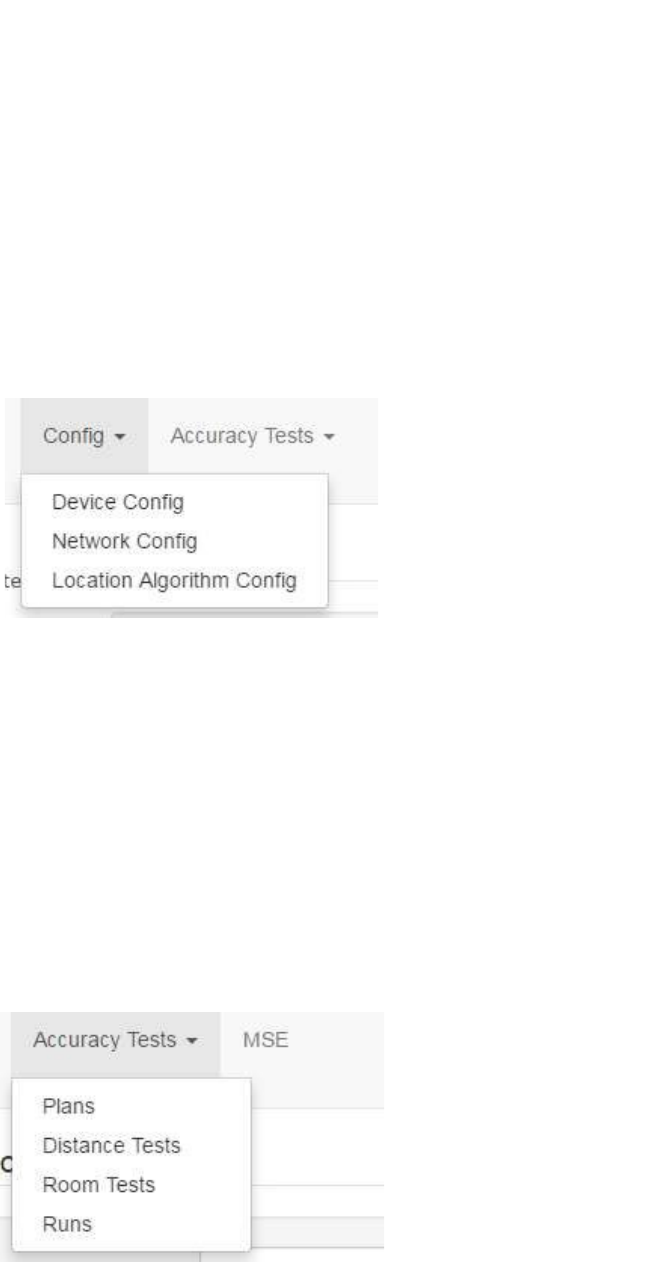
2.5 Config Tab
This tab provides three options:
• Device Config
• Network Config
• Location Algorithm Config
From this tab you can:
• Set configuration options for Tags and Beacons in the system
• Set network configuration options
• View and update location configuration settings
2.6 Accuracy Tests Tab
The Accuracy Tests tab allows you to load, run, and view results for accuracy tests.
Accuracy tests are critical to ensure items are communicating as required on the
network and for network certification.
From this tab you can:
• View, update, and create new accuracy test plans
7
System Manager User Guide |
System Manager 2.0
• View, update, and create new distance test plans
• View, update, and create new room test plans
• View accuracy test plan runs
2.7 MSE Tab
Clicking this tab brings you to the Mobility screen.
Figure 7 MSE Tab Screen
From this tab you can:
• Create new mobile device configurations
• Edit existing mobile device configurations
• Delete one or more mobile device configurations
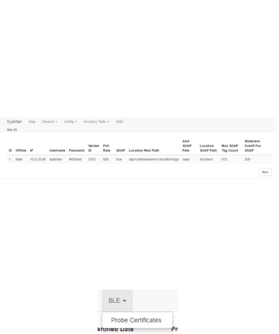
2.8 BLE Tab
The BLE tab provides access to the probe information and details for BLE probes.
From this tab you can:
• View uploaded probe certificates
• Edit existing probe information, including certificates
• Add new probes
8
System Manager User Guide |
System Manager 2.0
2.9 Site Selector
Located in the upper right corner of System Manager, clicking this link allows you to
select a different site from the one you are on.
Click this link to return to the Site Selector drop-down list.
Figure 8 Site Selector Drop-down List
9
System Manager User Guide |
System Manager 2.0
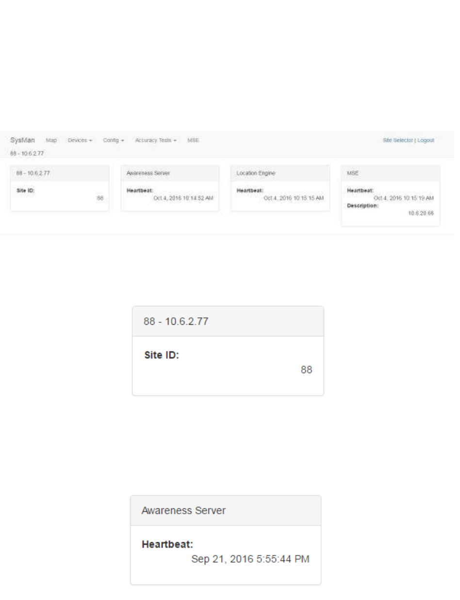
3 SysMan Tab
The Home screen, also available from the SysMan tab, provides a general overview of
the health and state of the system.
3.1 Site ID
This area of the screen displays Site ID information. The title bar displays the Site ID as
displayed in the Site Selector drop-down list. The information displayed shows the Site
ID number in the system. There are no user-configurable items in this area.
3.2 Awareness Server
The Awareness Server is a Java process on the Appliance that communicates with
devices (Tags and Beacons) on the network and publishes location determinations to
Infopoint and awareHealth. The Heartbeat indicates the last time the Awareness
Server was heard by System Manager. If the last Heartbeat was not recent, it may
indicate a problem that should be checked.
10
System Manager User Guide |
System Manager 2.0
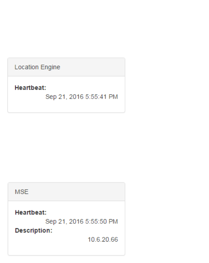
3.3 Location Engine
The Location Engine is an application responsible for providing location information for
devices (Tags and Beacons) on the network. The Heartbeat indicates the last time the
Location Engine was heard by System Manager. If the last Heartbeat was not recent, it
may indicate a problem that should be checked.
3.4 MSE
The Mobility Service Engine (MSE) provides Beacon report information. The Heartbeat
indicates the last time the MSE was heard by System Manager. If the last Heartbeat
was not recent, it may indicate a problem that should be checked.
The Description indicates the IP address on the network of the MSE.
11
System Manager User Guide |
System Manager 2.0
4 Map Tab
The Map tab provides access to floor maps of regions in the system.
Click the Map tab to display the Region Manager window.
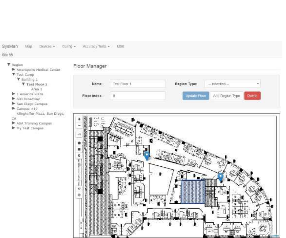
4.1 Viewing a Floor Map
1. From the list of the left, click the arrow next to the region that contains the floor
whose map you want to view.
When you click the arrow, levels underneath that region expand.
2. Click the arrow next to the building to view the floors.
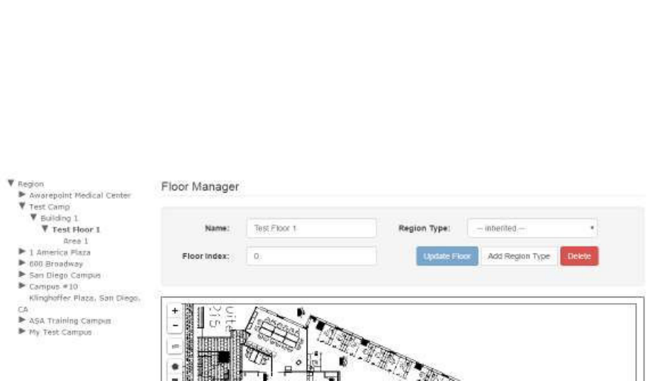
3. Select the floor you want to view by clicking the floor.
The floor will display in the Floor Manager window. If a map to the floor has
been uploaded, that map will also display.
12
System Manager User Guide |
System Manager 2.0
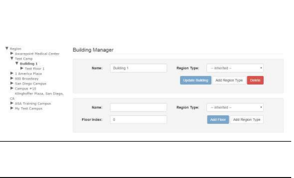
4.2 Adding a Campus/Building/Floor
The following procedure details the process for adding a floor. However, the process
for adding a campus or building is similar.
1. From the left-hand list, drill down to the building where you want to add the new
floor.
The Building Manager window displays.
13
System Manager User Guide |
System Manager 2.0
NOTE: To create a new item you must be at the parent level of that item. You
must be at the Region Manager window to create a campus, at the
Campus Manager window to create a building, and at the Building
Manager window to create a floor.
2. In the floor group of text boxes, enter a name for the new floor.
3. Select a region for the floor.
By default, this is set to Inherited to assign the floor to the current region. It is
unlikely you would need to change this. However, if you do, you can select a
region from this drop-down menu.
4. Enter a floor index.
Floor Index indicates the order in which the floor appears in the list of floors for
the building. By default, 0 is the same as all other categories, meaning the floors
will be sorted alphabetically. You can use this number to make items appear at
the bottom of the list by changing the number to something other than the
default.
5. Click Add Floor.
The floor now appears under the parent building in the list on the left.
4.3 Updating a Campus/Building/Floor
Updating a campus, building, or floor is limited to changing the name, the region, or the
index.
The following procedure updates a floor; however, the procedure is similar for updating
a campus or building.
1. From the list on the left, drill down to locate the floor you want to update.
14
System Manager User Guide |
System Manager 2.0
2. Select the floor.
The Floor Manager displays with the selected floor.
3. Make any changes to the Name, Region, and/or Floor Index text fields as
necessary.
4. Click Update Floor.
4.4 Adding a Map to a Floor
Floor maps allow a user to view a layout of a floor and locate Beacons placed on it.
Use the following procedure to add a map to an existing floor.
1. From the list on the left, drill down to the floor you want to add a map for and
select it.
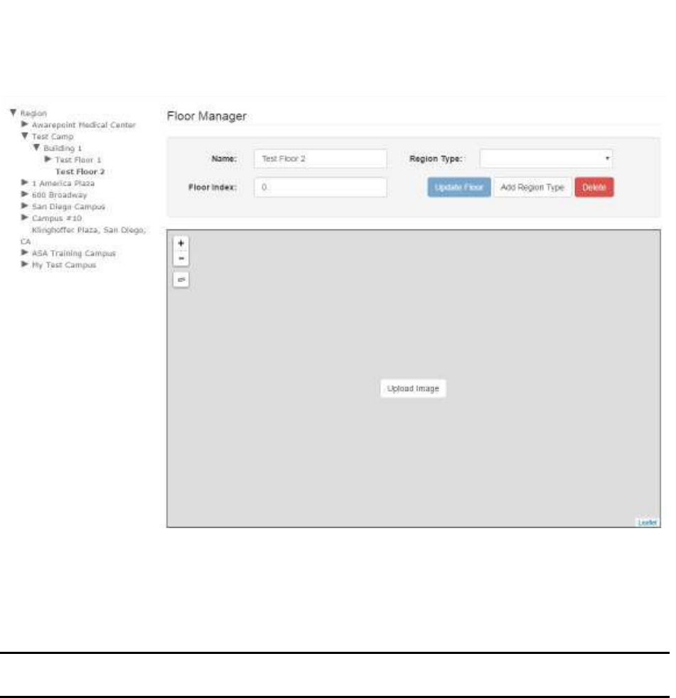
The Floor Manager window displays.
15
System Manager User Guide |
System Manager 2.0
2. In the map area, click the Upload Image link.
A file explorer window opens.
3. Navigate in the file explorer window to locate the map image file and select it.
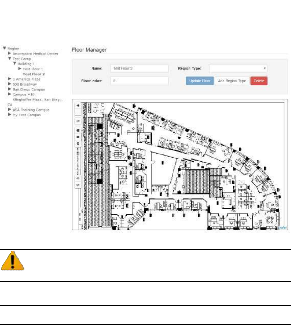
NOTE: Floor maps must be of an image file type such as JPEG or PNG. Higher
resolution images are preferable.
Once the floor map has uploaded, it displays in the window for the floor.
16
System Manager User Guide |
System Manager 2.0
4.5 Deleting a Campus/Building/Floor
Once a campus, building, or floor is deleted it cannot be recovered. Be
absolutely certain before deleting.
NOTE: Deleting a parent level item deletes all children beneath it. For example,
deleting a building deletes all floors in that building as well.
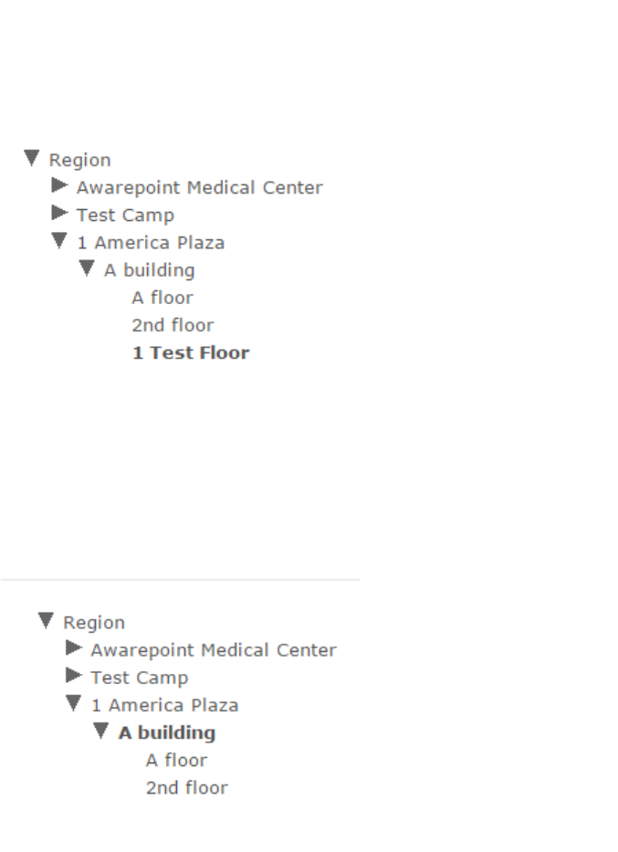
1. From the list on the left, drill down to the item you want to delete and select it.
The selected item is bolded in the list.
17
System Manager User Guide |
System Manager 2.0
2. In the manager window, click Delete.
If you are deleting a floor, the window will be the Floor Manager. If you are
deleting a building, it will be the Building Manager.
The floor will no longer appear in the list.
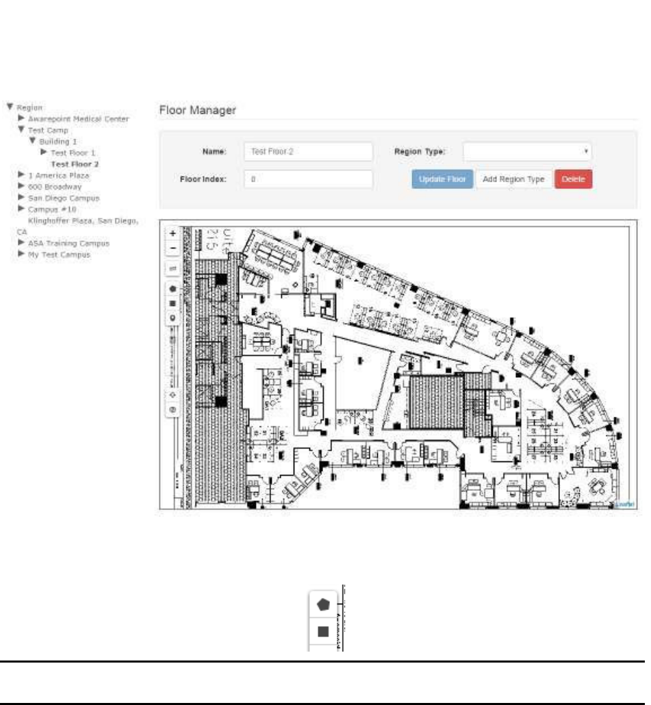
4.6 Defining an Area
In order to run a room test or for Tags to register entry/exit, you must define areas on
each floor that Tags will be on.
1. From the list of the left, drill down to find the floor where you want to define an
area and select.
The selected floor is bold and the map for the floor loads into the viewer.
18
System Manager User Guide |
System Manager 2.0
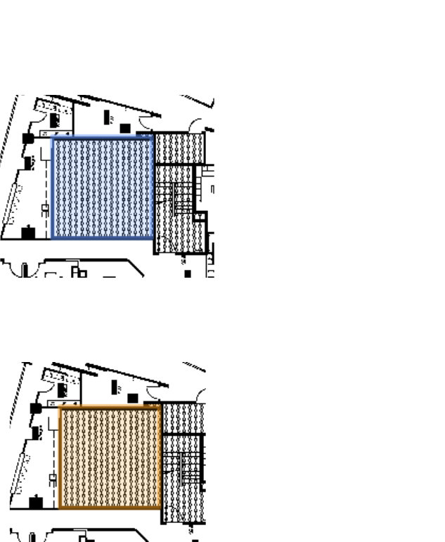
2. Using the polygon or rectangle tool, draw an outline around the area you are
defining.
NOTE: You may want to zoom in as much as possible on the map before starting
to define your area in order to make it as accurate as possible.
To complete a polygonal area, double-click after clicking the last point.
Once the area is completed it will be blue.
19
System Manager User Guide |
System Manager 2.0
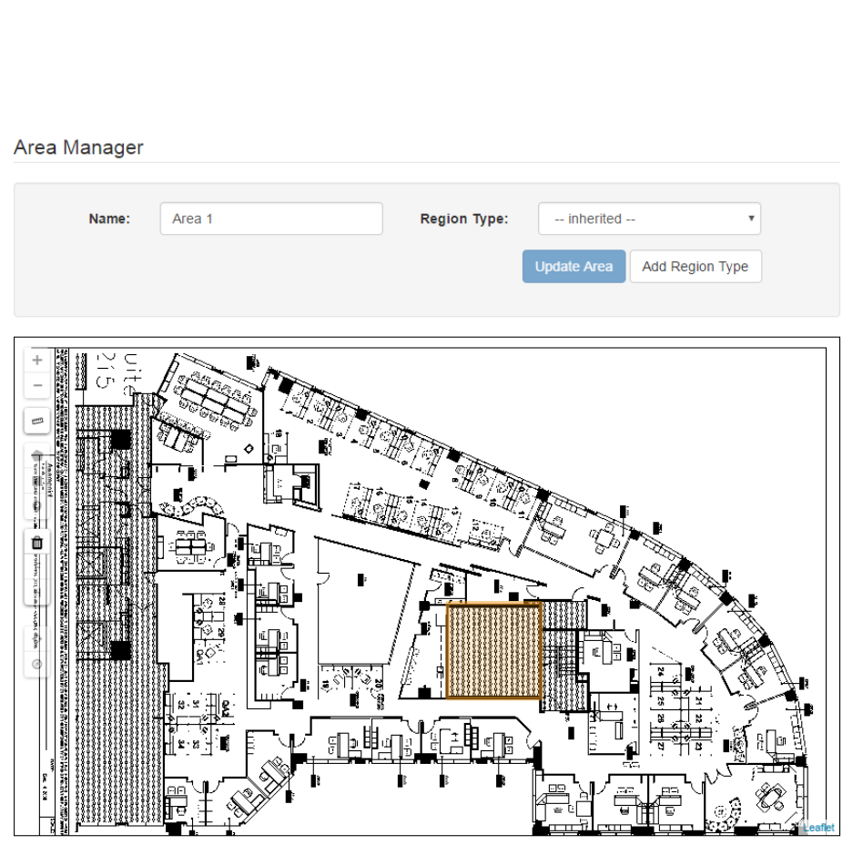
3. Single click the area once to select it.
The area turns orange.
4. In the Area Manager fields at the top, enter a name for the area then select a
region type from the Region Type drop-down list.
20
System Manager User Guide |
System Manager 2.0
Typical usage types include Patient Care Area or Cafeteria. See Region
Typing for standard region types.
5. Click Update Area to save your changes.
4.7 Region Typing
Regions in System Manager are inherited in a parent-child fashion. If the region type at
a Building Level is labeled as “Inherited,” it will by default inherit the region type of the
campus. The region types of a floor will, by default, inherit the region type of a building
and so on, through the Area and Room levels.
If a floor is comprised of a majority of one type of room, assign that region type to the
floor. All rooms will then inherit that region type. A user can then select the rooms that
are not of that region type and edit their region types.
21
System Manager User Guide |
System Manager 2.0
For example, if a floor is mainly comprised of patient rooms, select the floor and assign
its Region Type to Patient Room. Then begin selecting other areas like hallways and
restrooms and start assigning their appropriate Region Type. In doing this, the user will
not have to select any of the patient rooms to change their Region Type.
At the time of release of this document, the approved Region Types are as listed in the
following table.
Region Type Definition
Biomed / Clinical
Engineering
The office/shop space that is used by Biomed/Clinical Engineering
works.
Central Supply / Materials
Management
The office/department space that is used to receive, store, and
distribute medical and surgical supplies and equipment.
Clean Utility Room A utility room where clean, ready-to-use equipment and supplies
are stored.
Dirty Utility Room A utility room where trash, dirty items, or dirty supplies are stored.
Equipment Storage Any space that is being used to store equipment.
Exit Any area of egress into and out of the hospital.
Hallway Any corridor or walkway.
Laundry The area where laundry is laundered or stored to be sent out to be
laundered.
Linen A room on the patient floor where dirty laundry is held for pickup,
or clean linen is stored for patient use.
Maintenance Mechanical
Room
The maintenance area of the hospital.
Not In-Use Area Any areas where equipment would not be in clinical use and are
not defined as above such as stairwells, restrooms, and janitor
closets.
Nurse Station The central station on a unit that is used primarily by the nurses.
Office Any area used for administration.
Patient Care Area Short stay area that can include operating room (OR), physical
therapy, and radiology.
Patient Room Any overnight or long-term patient stay area.
Plant Operations The necessary infrastructure used in support of the maintenance
of the facility.
Shipping and Receiving The area where the hospital receives and ships its packages.
Sterile Processing The area used to sterilize hospital equipment.
Sterile Processing
Storage
The area used to store hospital equipment before and after
sterilization.
Waiting Area A lobby or waiting room for patients and/or family members.
22
System Manager User Guide |
System Manager 2.0
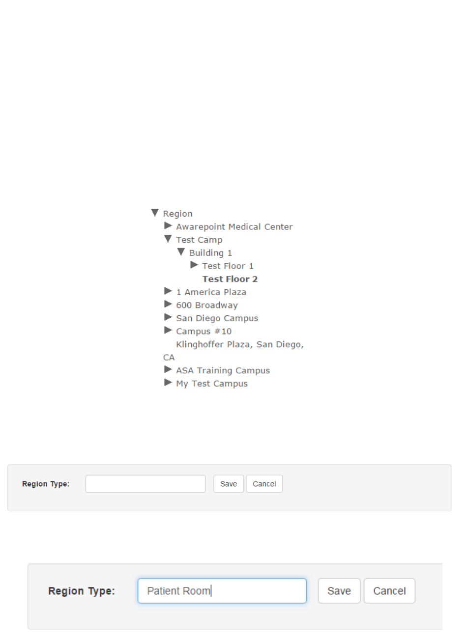
4.7.1 Adding a Region Type
All items in System Manager can be assigned a region type. The following example
provides the steps for adding a region type to a floor but can be used at the Region,
Campus, Building, and Area level as well.
1. From the list on the left, select the floor you want to assign a region to.
The floor will show as highlighted in the list.
2. In the Floor Manager, click the Add Region Type button.
The Region Type area displays.
3. Enter a type in the Region Type text area.
4. Click Save.
The floor is now assigned the Region Type of Patient Room.
23
System Manager User Guide |
System Manager 2.0
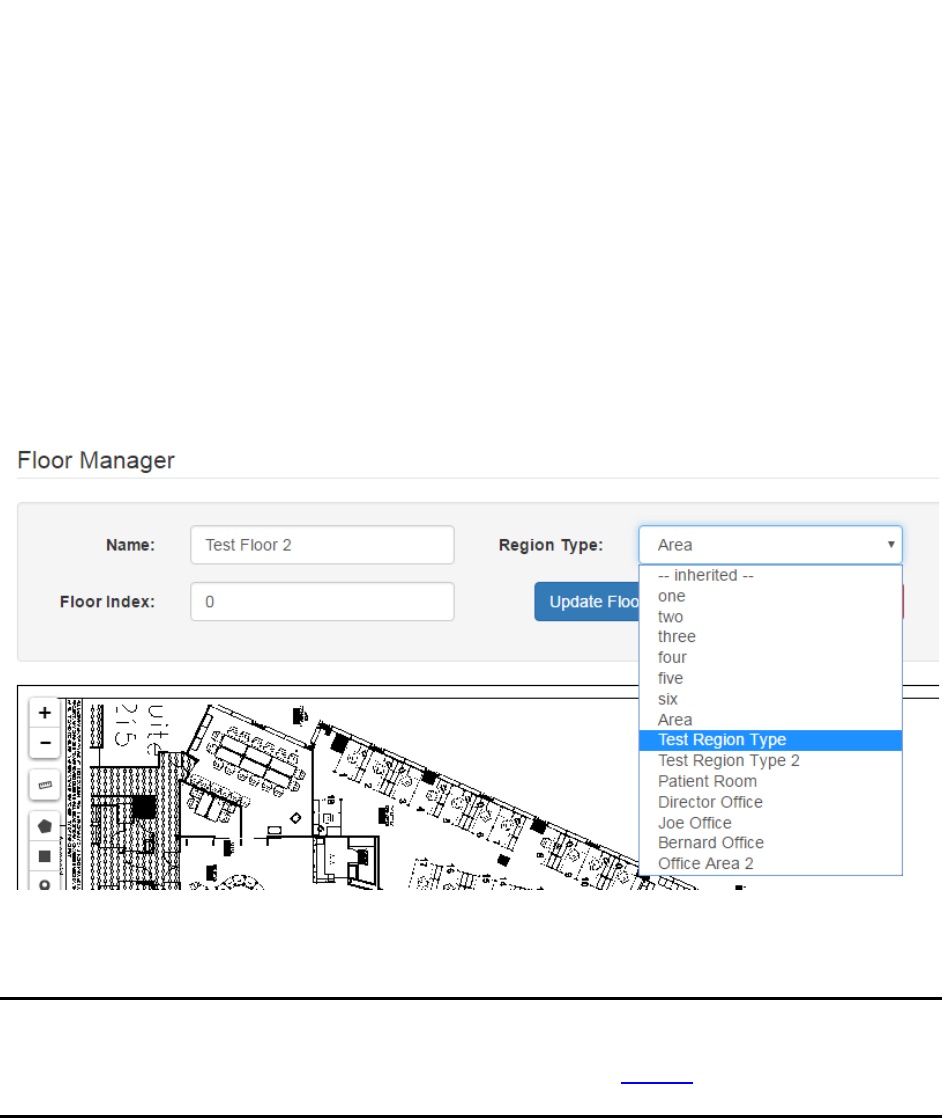
4.7.2 Changing a Region Type
Region Types are not fixed and can be changed as needed. The following procedure
provides the steps for changing the region type of a floor but can be used to change the
region type of a campus, building, or area as well.
1. From the list on the left, select the floor whose region type you want to change.
2. In the Floor Manager area, from the Region Type drop-down list, select the new
region type to assign to the floor.
3. Click the Update Floor button.
4.8 Placing a Beacon on a Map
NOTE: You can place a beacon on a map at any time; however, it will not connect
to the network and provide location information until after it has been
batch created and provisioned. Refer to the Create section for the
procedures to batch create and provision beacons.
1. Expand the list on the left to locate the floor where you will be placing the
beacon.
2. Click the floor.
The floor name will become bold in the list and the map of the floor displays.
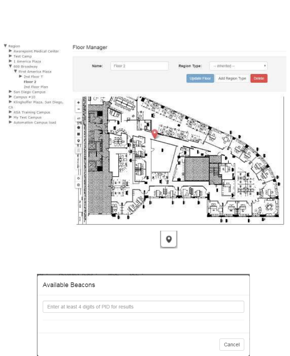
24
System Manager User Guide |
System Manager 2.0
3. Click the Place a Beacon icon on the left.
The Available Beacons dialog displays.
4. In the text field, enter at least 4 digits of the beacon’s PID to start a search for the
beacon.
A list of beacons matching the number you entered displays beneath the text
box.
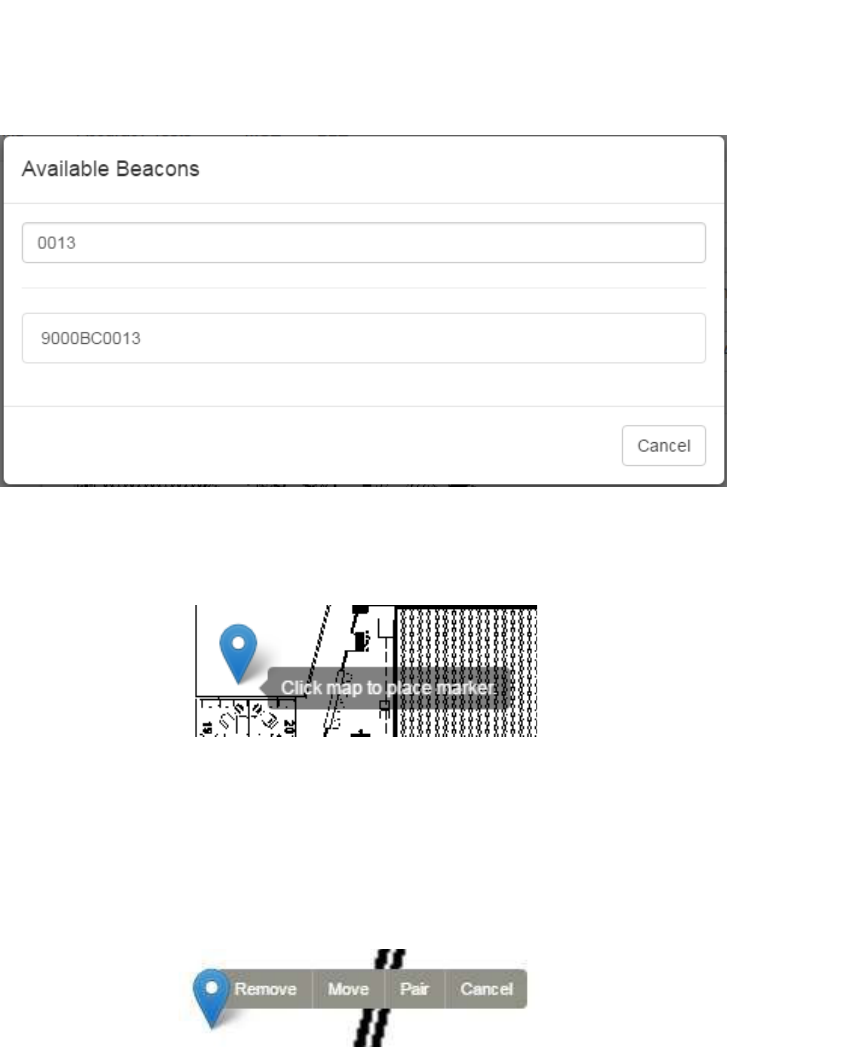
25
System Manager User Guide |
System Manager 2.0
5. Click the PID of the beacon you want to place.
The window disappears and your cursor appears with a beacon icon.
6. Zoom in on the map in order to place the beacon as accurately as possible.
7. Click on the map to place the beacon.
8. If you have placed the beacon in the wrong place or placed the wrong beacon,
click the beacon icon to display a list of options.
To move the beacon, click the Move link, then click and drag the icon to the new
location.
Click Cancel to cancel the operation and remove the icon.
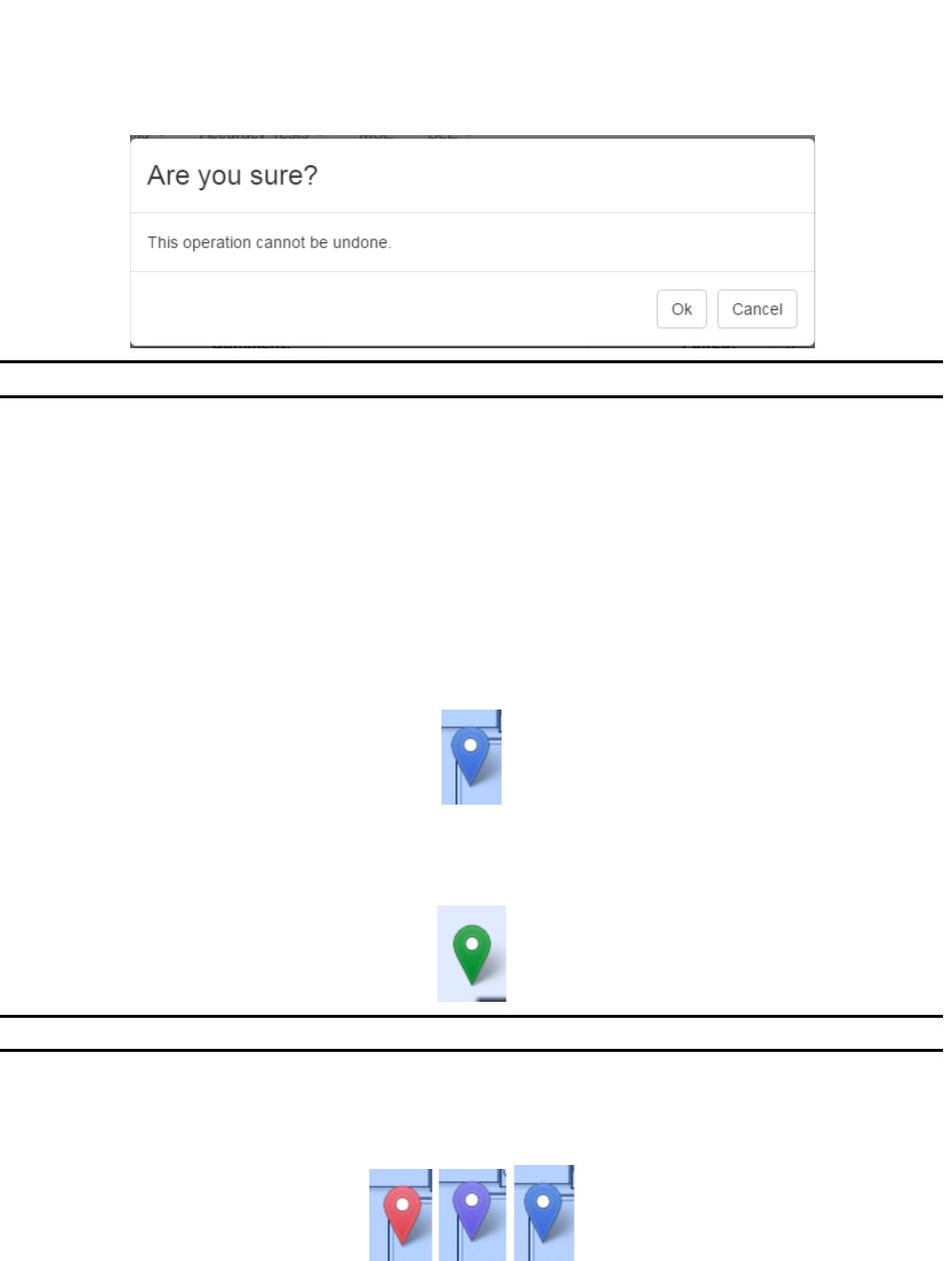
Click Remove to remove the beacon icon, then click Ok at the confirmation
dialog.
26
System Manager User Guide |
System Manager 2.0
NOTE: You can also use Remove to remove already placed beacons.
Click Pair to pair the beacon with another beacon for high accuracy.
4.8.1 Beacon Colors
As an added visual cue, once a beacon has been batch created, provisioned, and
placed on a map, it is color-coded to help in providing visual cues to its health on the
network. The colors are as follows:
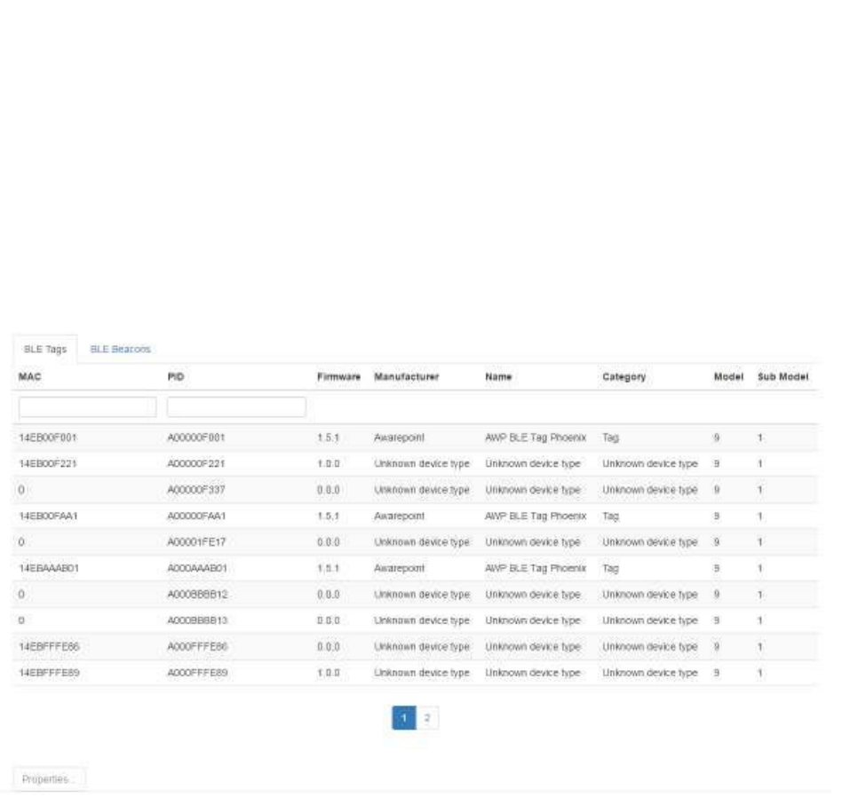
• Blue – The beacon is on the network and has sent a healthy status signal within
the last 4 hours
• Green – The beacon is on the network, has sent a healthy status signal within
the last 4 hours, and is paired with another beacon
NOTE: Green beacons appear in pairs or multiples.
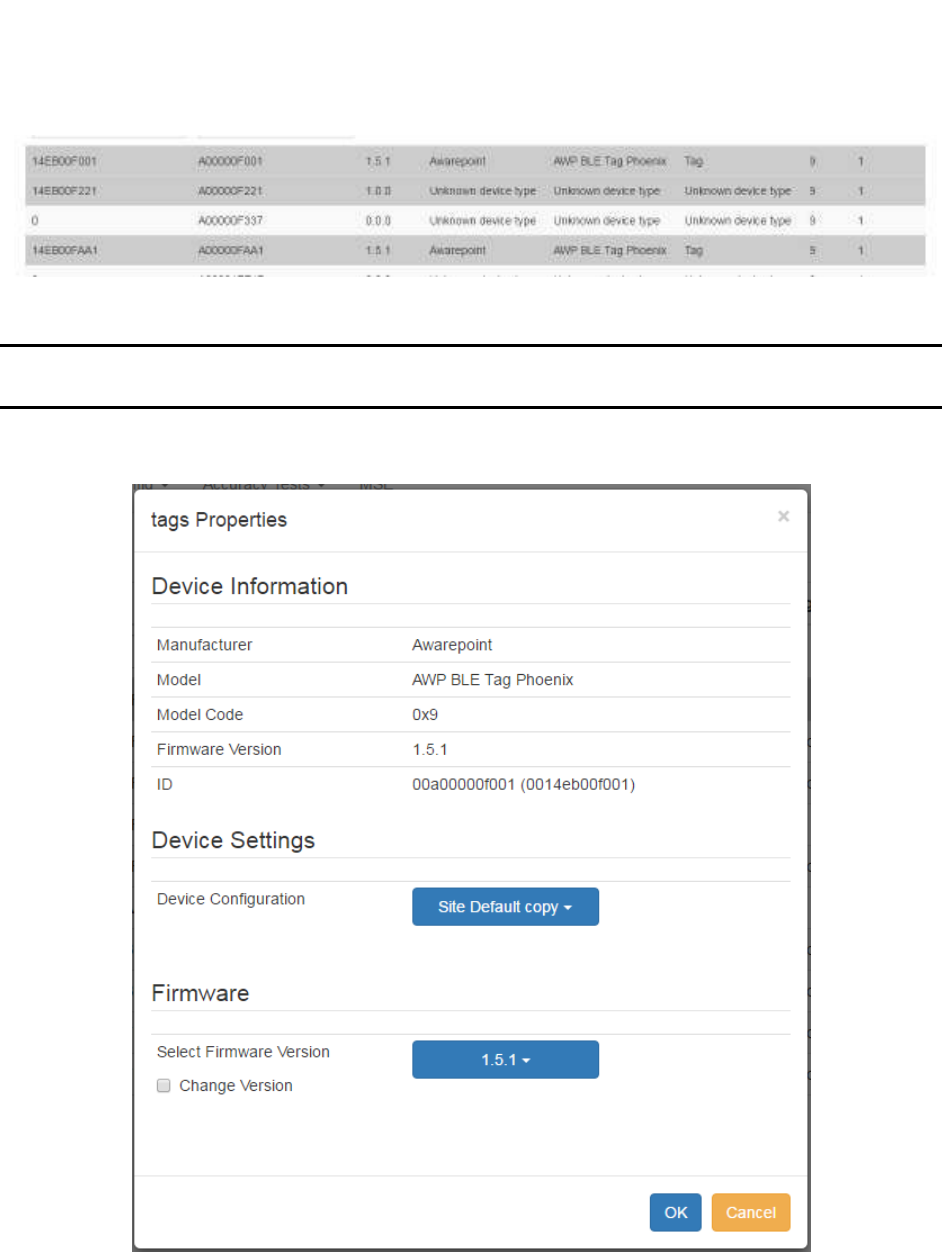
• Color changing – The beacon has not sent a healthy status signal within the last
4 hours; color changes constantly through red, purple, blue
27
System Manager User Guide |
System Manager 2.0
5 Devices Tab
The Devices tab allows for configuration and updating of the devices in the system.
5.1 Device Management
From the Device Management tab you can view all Tags and Beacons in System
Manager as well as any associated assets.
5.1.1 Viewing Device Properties
Use the following procedure to view a device’s properties.
1. From the Device Management tab, select the tab for BLE Tags or BLE
Beacons.
2. From the list, select the device whose properties you want to see by selecting the
device.
You can select multiple devices if desired.
Selected devices are shaded.
28
System Manager User Guide |
System Manager 2.0
3. Click the Properties button.
NOTE: The Properties button is grayed out and not available until you have
selected at least one device.
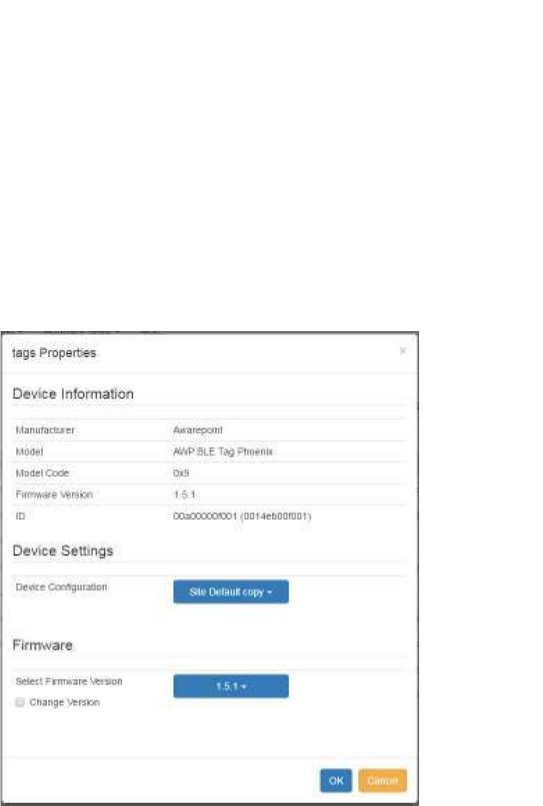
The Tag Properties window displays.
4. Click OK or Cancel to exit the window.
29
System Manager User Guide |
System Manager 2.0
5.1.2 Changing a Device’s Settings or Firmware
1. From the Device Management tab, select the tab for BLE Tags or BLE
Beacons.
2. From the list, select the device whose properties you want to see.
You can select multiple devices by clicking multiple items.
3. Click the Properties button.
The Tag Properties window displays.
4. To change the device settings, click the dropdown menu item next to Device
Configuration.
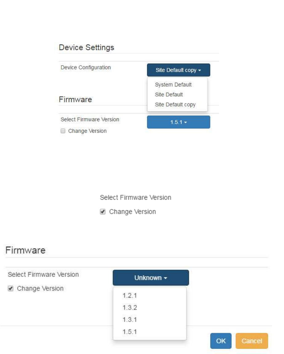
30
System Manager User Guide |
System Manager 2.0
5. Select the configuration you want to apply.
6. To select a firmware version, first check the box for Change Version to confirm
that you want to change the firmware version.
7. Click the dropdown next to Select Firmware Version.
8. Select the firmware version you want to apply.
9. Click OK to save your changes and exit the window.
Before Tags and Beacons can be associated with assets or placed on maps, they must
first be batch created in System Manager. Similarly, when Tags or Beacons are
permanently removed from service for whatever reason, they can be removed from
31
System Manager User Guide |
System Manager 2.0
System Manager. Tags and Beacons are imported (created) into System Manager or
deleted from System Manager from the Batch tab.
5.2 Device Map
The Device Map screen provides a map where environmental devices (tags) can be
manually placed on a map for location purposes instead of relying on location engine
determinations.
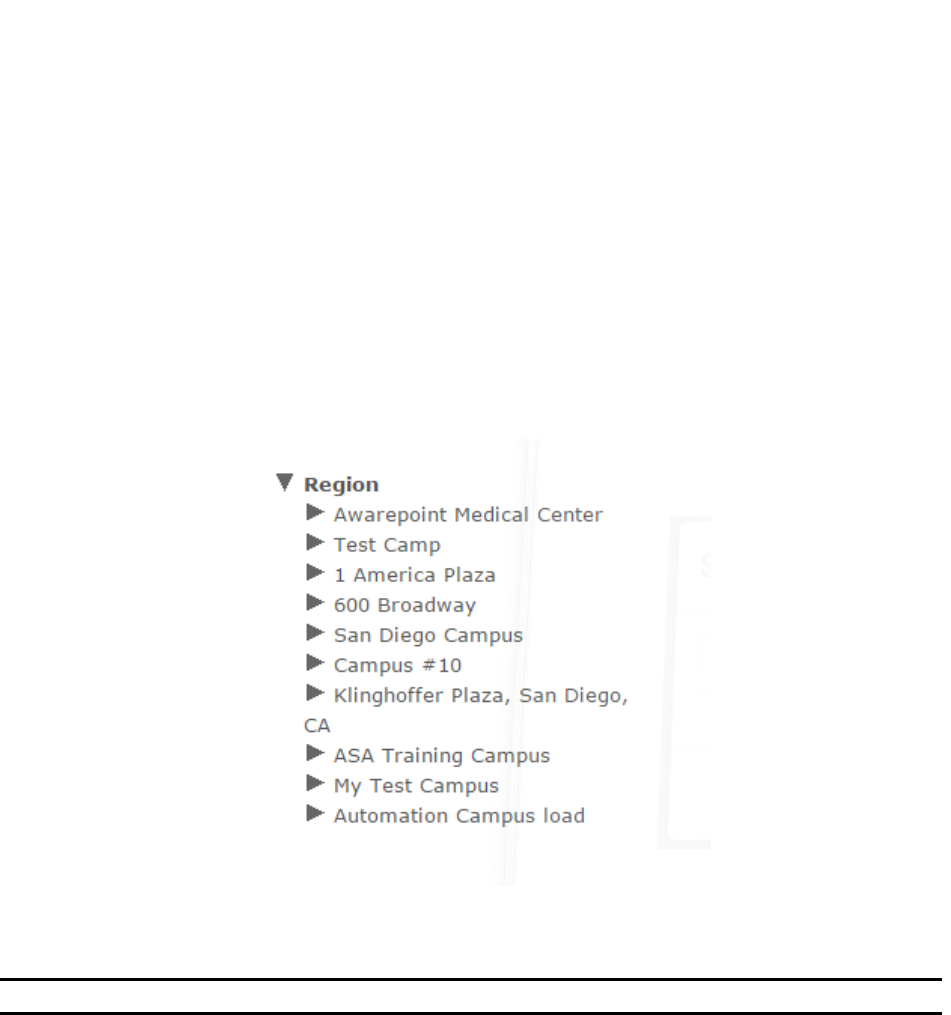
From the Devices tab drop-down, select Device Map. A region explorer, similar to the
one that displays under the Map tab, displays:
From this explorer, you can select a floor to place the environmental tag or to view
already placed tags.
NOTE: Maps must have been pre-loaded into System Manager
5.2.1 Placing an Environmental Tag
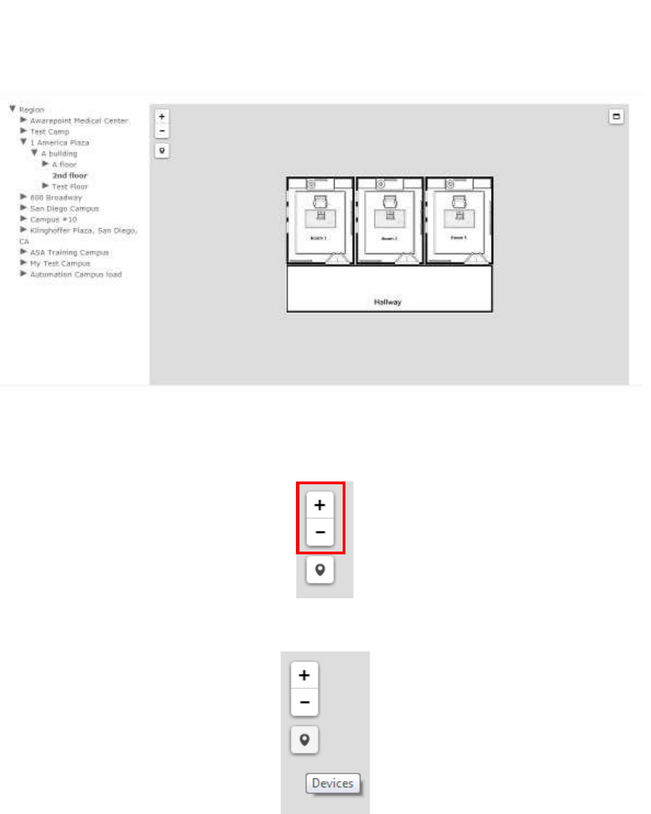
1. From the Region explorer list, find the floor you want to place the marker on for
the environmental tag and click it.
The floor map for the selected floor displays next to the explorer list.
32
System Manager User Guide |
System Manager 2.0
2. Use the plus and/or minus sign to expand the map as large as necessary for
accurate device placement.
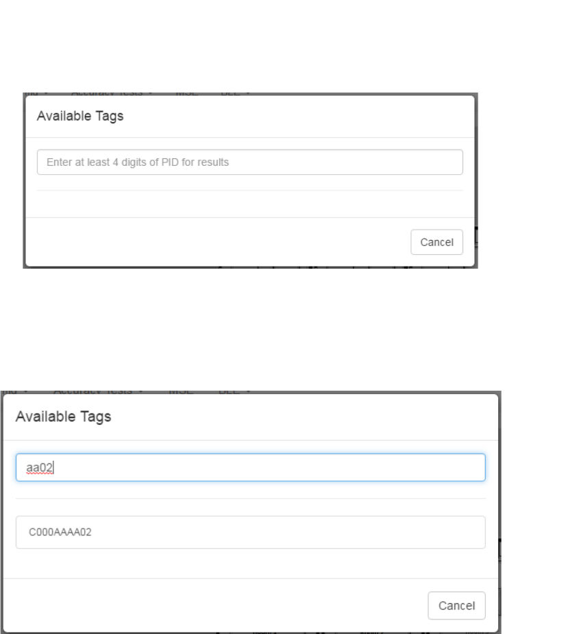
3. Click the Devices marker beneath the plus/minus settings.
The Available Tags window displays.
33
System Manager User Guide |
System Manager 2.0
4. In the text box, enter at least 4 consecutive digits of the PID for the
environmental tag you want to place on the map.
A list of available tags matching the PID digits entered displays beneath the text
box.
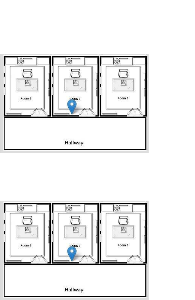
5. From the list of available devices, left click the one you want to place on the map.
A blue marker displays on the map.
34
System Manager User Guide |
System Manager 2.0
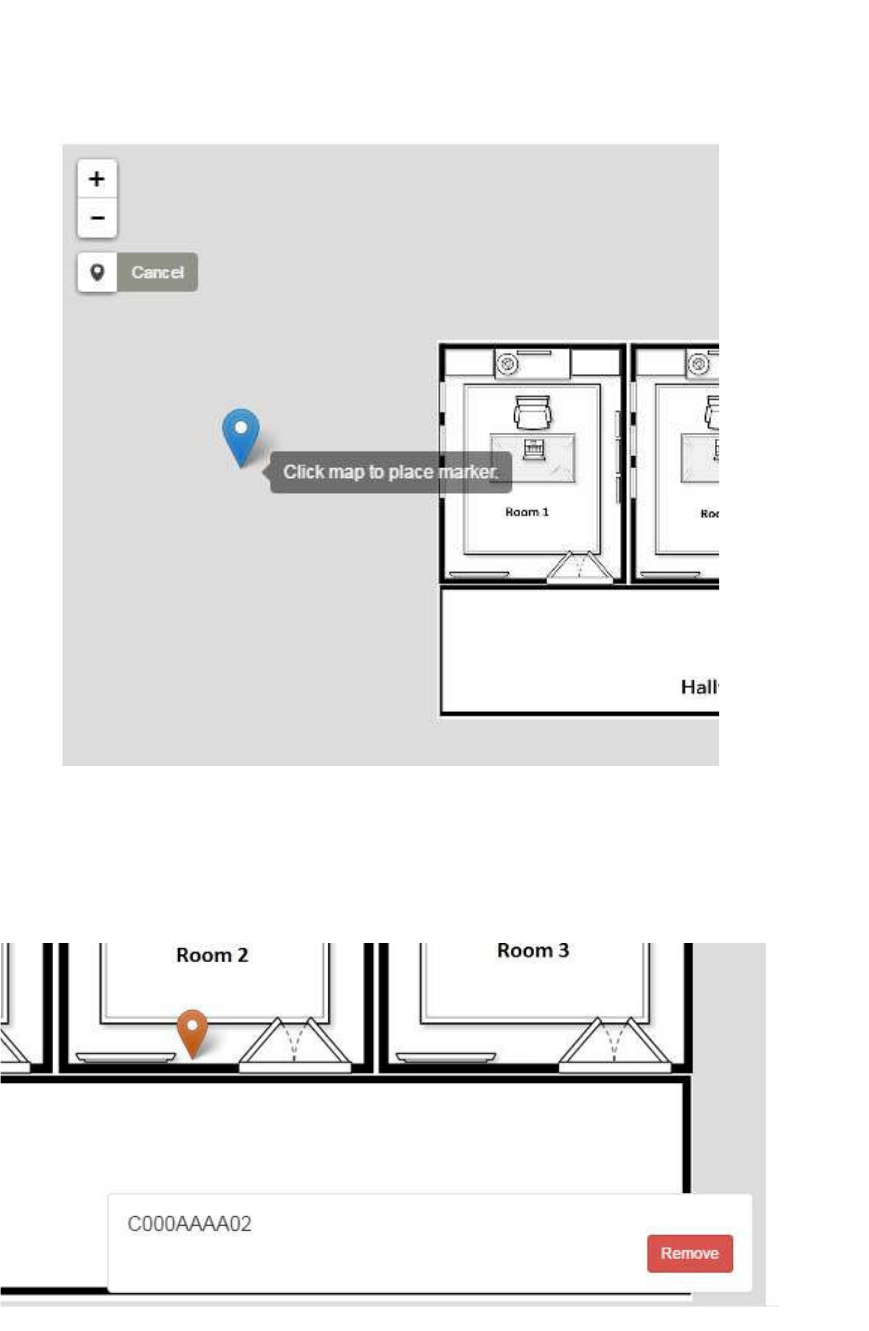
6. Zoom in on the map as necessary, then place the marker in the location of the
tag.
The marker changes color to orange and a Remove dialog displays should you
need to remove the tag from its current placement.
The Remove dialog stays as long as you are on the current map or until you
select a new device to place. Once you click away from the map, such as
35
System Manager User Guide |
System Manager 2.0
selecting another floor, and click back, the marker displays as blue without the
Remove dialog.
5.2.2 Removing a Place Marker
1. From the Region explorer list, navigate to the floor where you want to remove an
environmental tag marker and select the floor.
The map of the floor displays with the marker in blue.
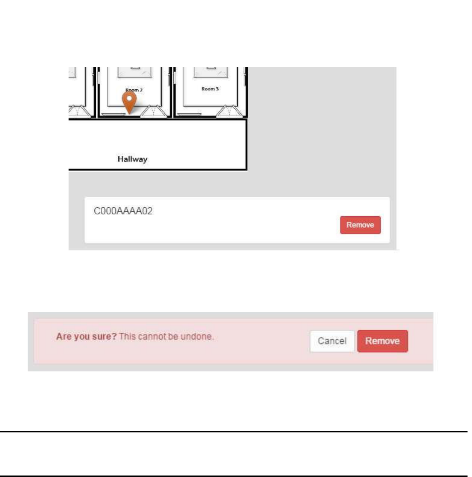
2. Left click once on the marker.
The marker changes color to orange and the Remove dialog displays showing
the environmental tag’s PID.
36
System Manager User Guide |
System Manager 2.0
3. Click the Remove button.
The Remove dialog changes to a confirmation dialog.
4. Click Remove.
The marker is removed from the map.
NOTE: This does not remove the environmental tag from the system. Removing
the tag from the map means that the location of the tag will now be
determined by the location engine.
5.3 Device Status
The Device Statuses screen displays a list of devices (Tags and Beacons) in the
system and their status.
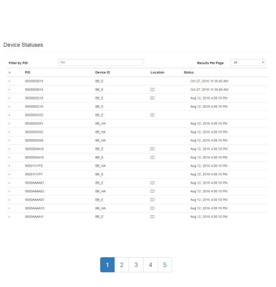
From the Devices tab drop-down, select Device Status. The Device Statuses screen
displays, listing all Devices by their PID.
37
System Manager User Guide |
System Manager 2.0
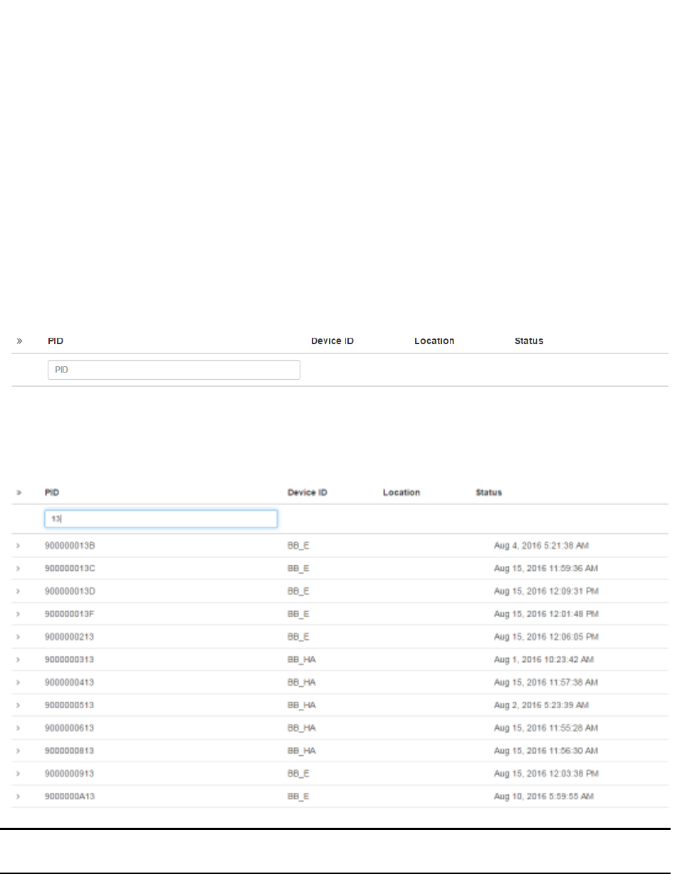
If there are more devices than can be seen on the initial screen, a row of clickable page
numbers displays at the bottom of the list.
The Device Statuses screen contains the following columns:
• PID – Product Identification number of the device
• Device ID – Device Identification for device type
• Location – Location of the device; for devices that have been placed, location is
a clickable link to display device on map
• Status – Shows the last time a status message was received from the device
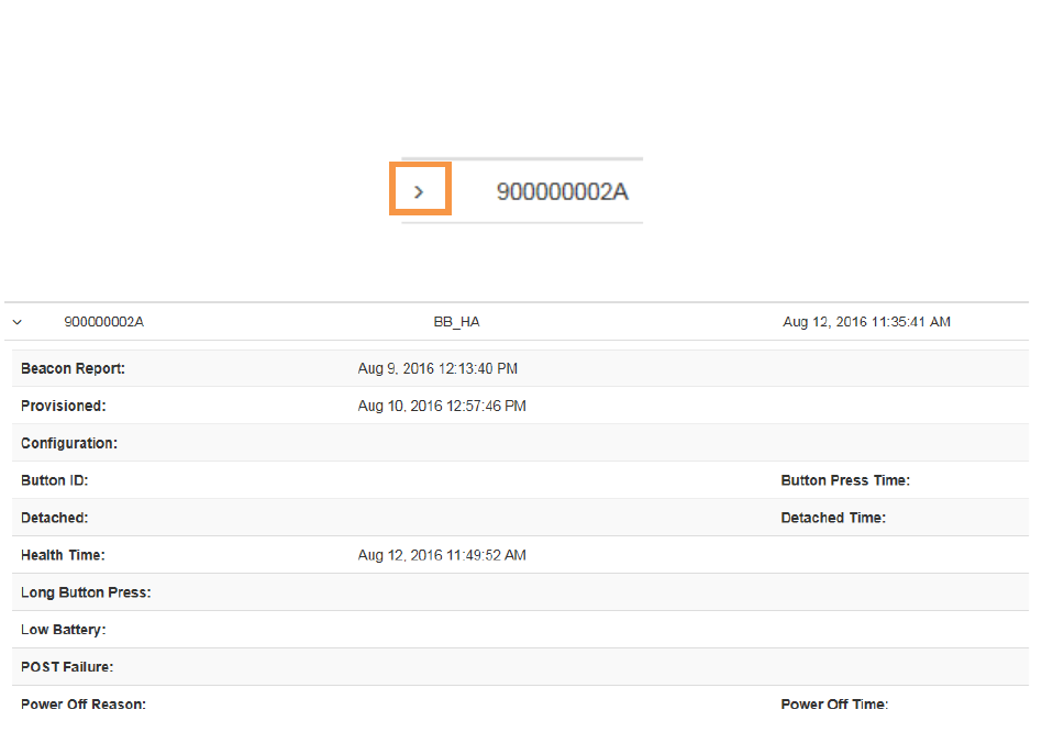
Additional information on each device can be viewed by clicking the arrow to the left of
the device PID.
38
System Manager User Guide |
System Manager 2.0
The following device information displays:
• Beacon Report (Beacon only) – The last time this Beacon was heard by a Tag
and included in a Beacon report
• Provisioned – Date and time the device was provisioned
• Configuration – Date and time the device was last configured over the network
• Button ID (Tag only) – Identification number of the button
• Button Press Time (Tag only) – Date and time the Tag’s button was last
pressed
• Detached (Tag only) – If Tag is set to alert when removed, the date the Tag was
removed
• Detached Time (Tag only) – If Tag is set to alert when removed, the time the
Tag was detached
• Health Time – Date and time of the last health report where the device
responded
• Long Button Press (Tag only) – Indicates if the last button press was long
• Low Battery – Indicates if the device’s battery was run low
39
System Manager User Guide |
System Manager 2.0
• POST Failure – Date and time of any failures for the device during Power-on
Self Test (POST)
• Power Off Reason – Reason listed for powering off the device
• Power Off Time – Date and time device was powered off
5.3.1 Filtering Devices
If there are more devices that can be displayed on one page, you can use the filter box
located just below the PID column heading.
This filter box allows you to filter displayed devices by PID. Entering the device’s PID,
or part of it, filters the displayed device list to those devices that match the search
criteria.
NOTE: It is not necessary to press ENTER to begin the search. The filter box is
dynamic and will begin filtering as criteria is typed in.
5.4 Environmental Tag/Display Pairings
The Environmental Tag/Display Pairings screen displays a list of devices
(environmental tags) and the displays they are paired to.
40
System Manager User Guide |
System Manager 2.0
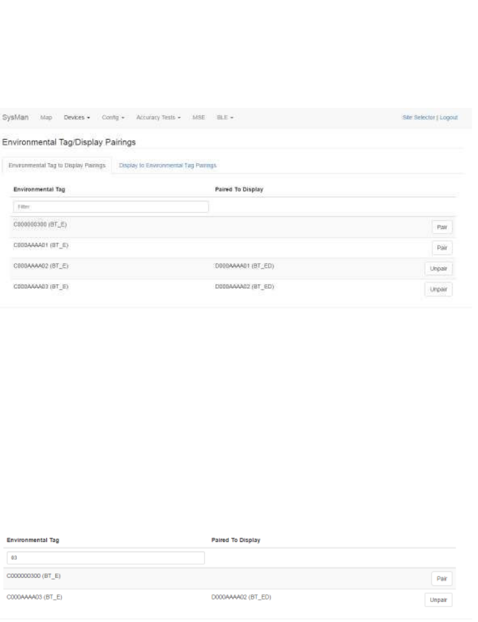
From the Devices tab drop-down, select Environmental Tag/Display Pairings. The
Environmental Tag/Display Pairings screen displays:
5.4.1 Environmental Tag to Display Pairings Tab
By default, the Environmental Tag to Display Pairings tab displays first in the
Environmental Tag/Display Pairings window. This tab displays all environmental
tag/display pairings by environmental tag.
The Environmental Tag column, on the left, displays all environmental tags in the
system, sorted alphanumerically. The Paired to Display column, in the middle,
displays only environmental displays that have been paired with an environmental tag.
The third column, on the right, contains the buttons to pair or unpair tags and displays.
The Filter textbox is a dynamic search box. Enter any part of a tag’s PID and the list
below displays only those tags that match your search criteria.
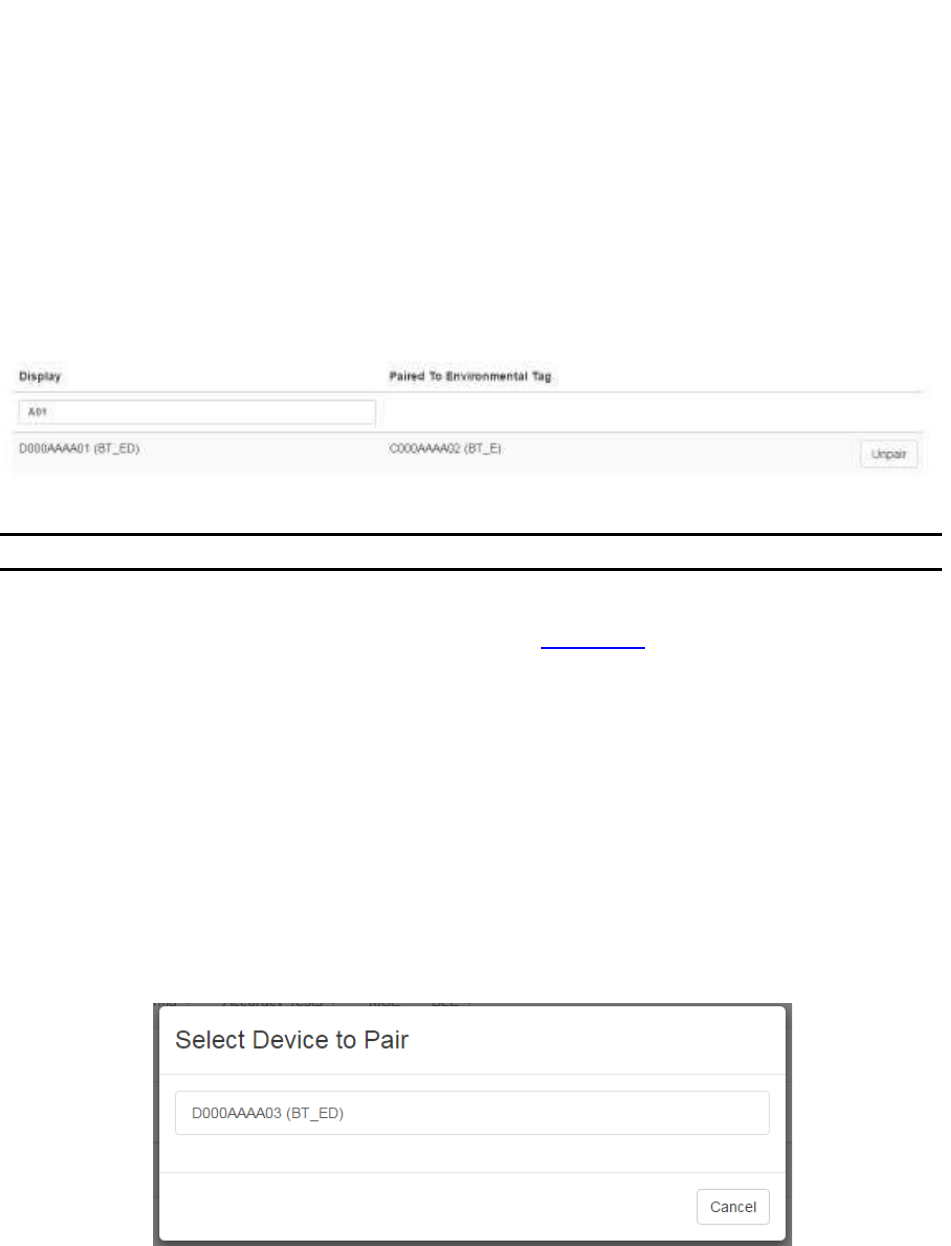
5.4.2 Display to Environmental Tag Pairings Tab
The Display to Environmental Tag Pairings tab displays all environmental tag/display
pairings by environmental display.
41
System Manager User Guide |
System Manager 2.0
The Display column, on the left, displays all environmental displays in the system,
sorted alphanumerically. The Paired to Environmental Tag column, in the middle,
displays only environmental tags that have been paired with an environmental display.
The third column, on the right, contains the buttons to pair or unpair tags and displays.
The Filter textbox is a dynamic search box. Enter any part of a display’s PID and the
list below displays only those displays that match your search criteria.
5.4.3 Pairing Devices
NOTE: Only environmental tags and displays can be paired.
Only environmental tags and displays that have already been batch created can be
paired. If you have not batch created the devices, do so first before continuing with the
following procedure.
1. From the Environmental Tag/Display Pairings window, locate the device
(environmental tag) you want to pair with a display.
Only devices that are eligible for pairing display in the first column. Additionally,
the second column for eligible devices will be blank. On the far right, the Pair
button for that device is available.
2. Click the Pair button on the far right in that device’s row.
The Select Device to Pair window displays.
Only devices eligible for pairing appear in this window.
3. Left-click the device you want to pair.
42
System Manager User Guide |
System Manager 2.0
The devices are paired and now display as paired in the Device Pairings
window.
5.4.4 Unpairing Devices
1. From the Environmental Tag/Display Pairings window, locate the devices you
want to unpair.
2. On the far right of the row with the devices you want to unpair, click the Unpair
button.
The devices are now unpaired and show as eligible to be paired in the Device
Pairings window.
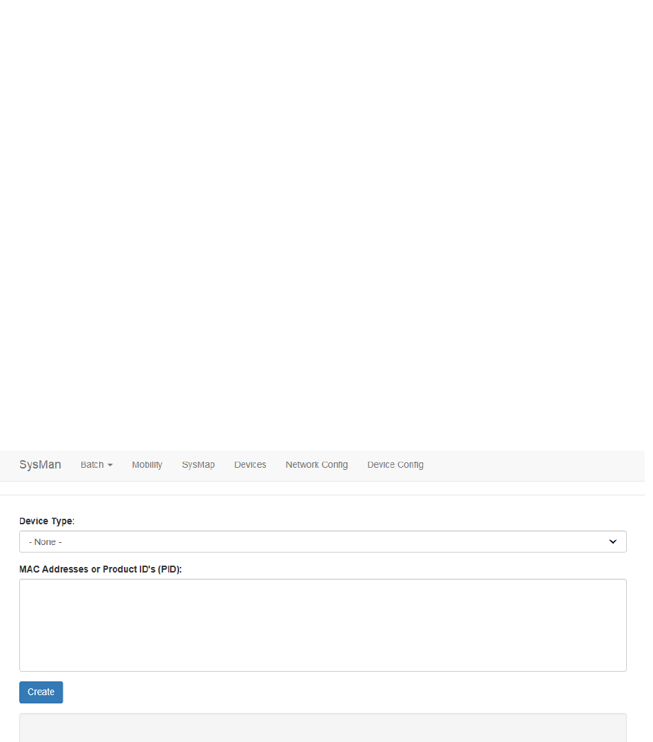
5.5 Create
1. From the Devices tab drop-down, select Create.
The Batch Create screen displays.
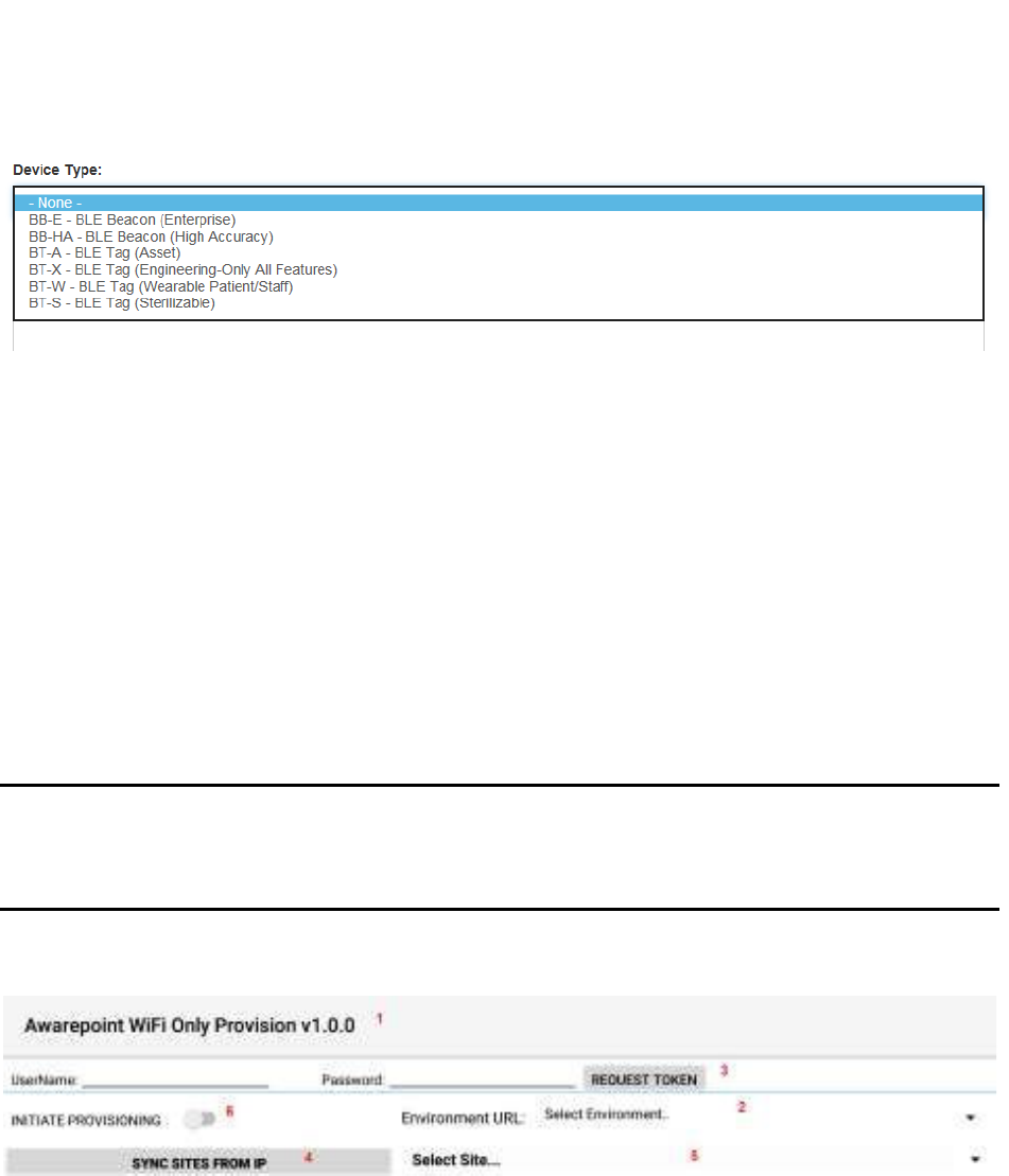
2. From the Device Type drop-down, select the type of device you are creating.
43
System Manager User Guide |
System Manager 2.0
3. In the MAC Addresses or Product ID's (PID): field, enter the MAC address or
product ID (PID) of the device or devices.
You can copy and paste this information or enter it by hand. Different MAC
addresses or PIDs must be separated by commas or by carriage returns (one
item per line).
4. Click Create.
5.5.1 Provisioning Beacons
After a device (beacon) has been created, it must be provisioned so that it can connect
to the network and provide location information for tags. Use the following procedure to
provision beacons.
NOTE: Before beginning this procedure, an Awarepoint router must be connected
and running close to the tablet running the provisioning application.
Without this router, the SSID for the site will not be available to the app
and the provisioning procedure will fail.
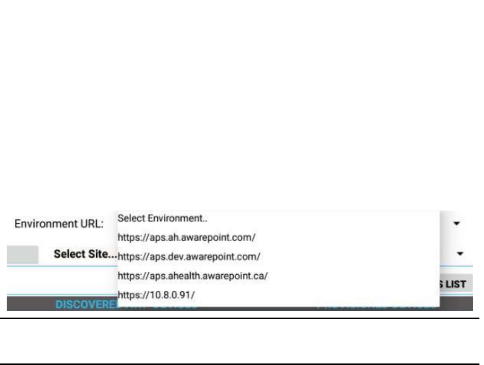
1. Open the Provisioning app on the Awarepoint tablet.
Figure 9 Provisioning Application Main Screen
The following areas should be noted as identified in the figure above:
1) Application version
2) The Environment URL drop-down list
3) The REQUEST TOKEN button
4) The SYNC WITH SITES FROM IP button
44
System Manager User Guide |
System Manager 2.0
5) The Select Site drop-down list
6) The INITIATE PROVISIONING slider
2. Enter the username and password for connection to the Awarepoint web
services.
3. From the Environment URL drop-down list, select the environment you are
going to request the token from.
NOTE: There are four main environments to select from. Each environment has
different sites associated with it, so be careful to choose the correct
environment.
4. Press the Request Token button.
If the username and password were correct, a success message displays.
If you do not see a success message, re-enter the username and password and
verify the Environment URL. If you still do not see a request message, contact
the account manager to verify the credentials or to see if there is an outage.
5. Press the SYNC WITH SITES FROM IP button.
Pushing this button pulls a list of all sites associated with the selected
Environment URL.
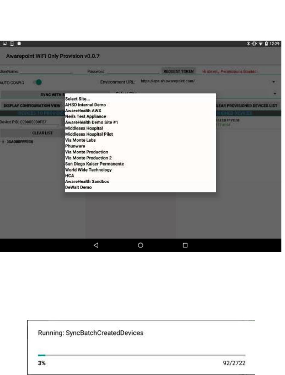
6. From the Select Site drop-down, select the site to synchronize with.

45
System Manager User Guide |
System Manager 2.0
Figure 10 Sample Site List
Once you select a site, the SYNC WITH SITES FROM IP button changes to
SYNC WITH SITE.
7. Push the SYNC WITH SITE button.
This option requires an Internet connection.
You must wait until this step completes without any error before proceeding to
the next step. If an error occurs, attempt to SYNC WITH SITE again. If this step
does not complete due to an error, the data will not be available for provisioning
devices.
8. After successful synchronizing with the site is complete, change the Wi-Fi
Network to the SSID named AWP_PROVISION_SERVER.

46
System Manager User Guide |
System Manager 2.0
This is the SSID in the Awarepoint router. The router must be preconfigured with
the specific security options and the correct SSID name.
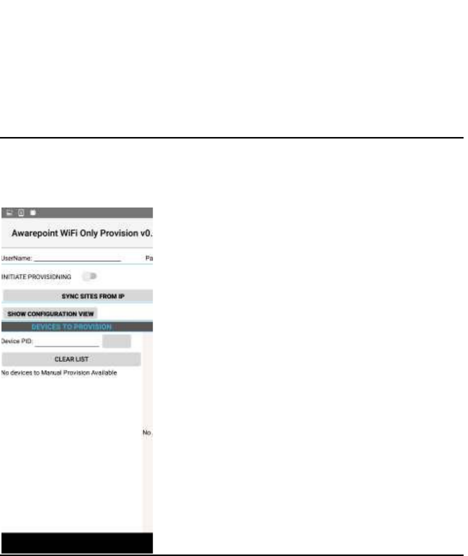
9. Slide the INITIATE PROVISIONING slider to the ON position.
Figure 11 INITIATE PROVISIONING in OFF Position
Figure 12 INITIATE PROVISIONING in ON Position
Initiating provisioning does two things:
o Creates a Network Service Discovery that allows the tablet to start
listening for devices in the same network
47
System Manager User Guide |
System Manager 2.0
o Creates an SSL Server socket site in order to start communication with
the devices
10. Power cycle the beacon by pulling the battery out and replacing.
NOTE: If the DEVICES TO PROVISION section is empty (clear list), the tablet will
try to provision every Awarepoint device. If the list is not empty and you have entered
specific device PIDs, the tablet will detect the devices (will appear in DISCOVERED
AWP DEVICES section) but will just provision the devices in the list. Other devices will
be ignored.
11. From the Environment URL drop-down, select the Awarepoint environment you
want to pull network data from.
12. Enter the username and password in the appropriate fields.
These are the credentials to have access to execute the REST Web services to
pull configuration data. This is an Oauth2 security type.

48
System Manager User Guide |
System Manager 2.0
13. Press the Request Token button.
If the connection is successful, a Permission Granted message displays.
If you receive a Permission Denied message, check the Environment URL,
username, and password, and retry. If you are still denied, contact the account
manager.
14. Press the SYNC SITES FROM IP button.
This executes a call to pull every site for the Environment URL selected.
When the process of pulling the sites is complete, the SYNC SITES FROM IP
button changes to SYNC WITH SITE.
15. Select a site from the drop-down next to the SYNC WITH SITE button.
49
System Manager User Guide |
System Manager 2.0
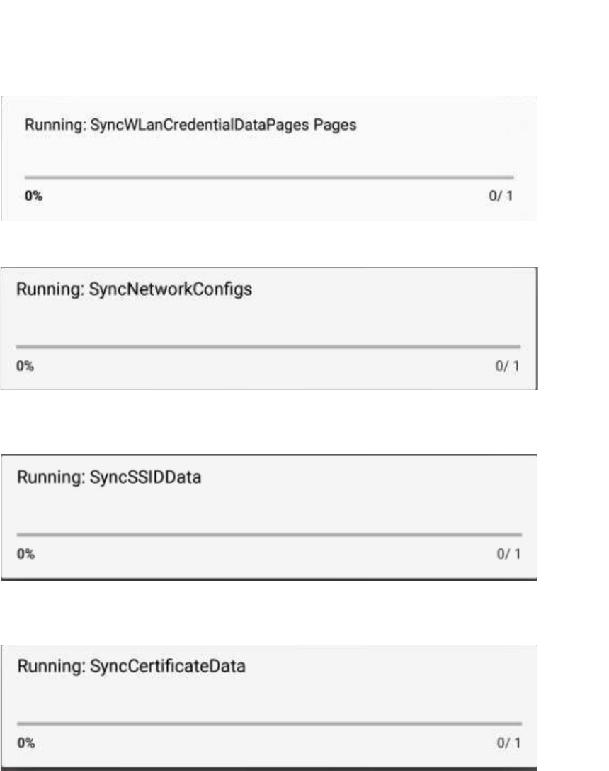
16. Press the SYNC WITH SITE button.
This begins the data pulling process. Progress bars display at each stage of the
process.
a. Pull Batch Created devices: If the device is not batch created in the system, it
cannot be provisioned.
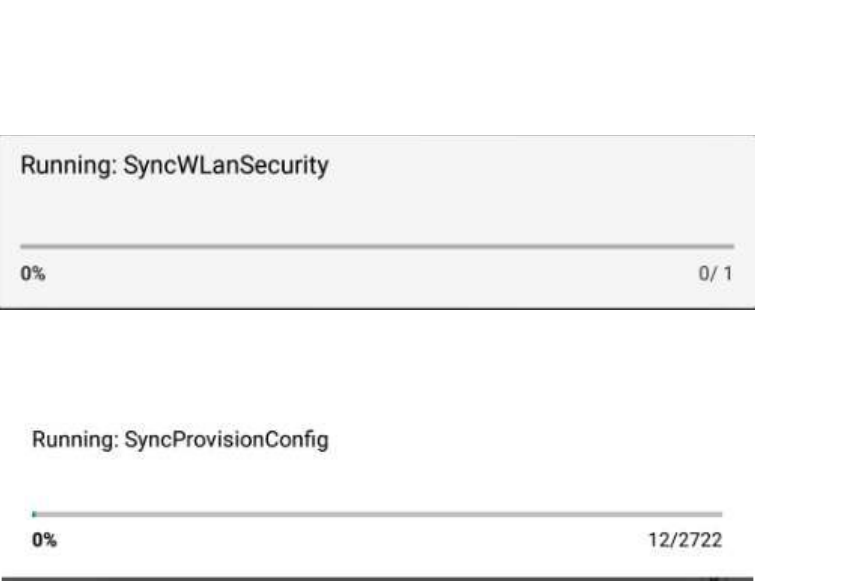
b. WLanCredentialData: Contains the username and password for an individual
device or a group of devices or a single user and password for the whole site.
50
System Manager User Guide |
System Manager 2.0
c. NetworkConfig: Contains the hostname by name or IP.
d. SSIDData: Contains the SSID for an individual device or a group of devices or
a single user and SSID for the whole site.
e. CertificateData: Contains the certification information, private key and ca
Certificate Root. Note that some sites do not require certificate information.
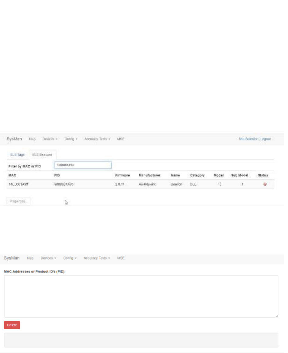
f. WLanSecurity: contains the security information: EAP Method and security
type.
51
System Manager User Guide |
System Manager 2.0
g. The last step in the process is to put all the pieces together in order to have
each device have a full configuration.
17. Be sure that the AUTO SCAN and AUTO CONFIG sliders are set to the on
position.
18. After the MAC address of the beacon shows up in the discovered AWP devices
list, click the MAC address.
19. When the Start WiFi Provisioning button displays, press it.
20. Once the beacon is provisioned successfully, the PID of the beacon shows in the
Provisioned Devices list.
During the provisioning process you can monitor the awarepoint.log file on the
appliance using the following command:
tail -F /var/log/tomcat/awarepoint.log| grep -i
'configuration\|error\|exception'| grep -vi 'mse\|pong\|
mapHierarchyString'
When the device is configured you should be able to see a configuration
message similar to the following sent back to the device:
2016-10-12 11:06:25,752 [BleWifiActorSystem-akka.actor.default-
dispatcher-13] DEBUG
com.awarepoint.blewifiserver.infrastructure.actors.ble.ConfigurationHa
ndler - sendConfigurationResponse EncodeResponse{mac=89842000652,
hexMac='14EB00230C', message=Message{header=BleHeader{version=4,
messageType=CONFIGURATION, mac=89842000652, hexMac='14EB00230C',
ackRequested=true},
body=Configuration{nvpList=[Nvp{oid=WIFI_BEACON_REPORT_OFF_SAMPLE_INTE
RVAL_ZONE_6, dataString=0},

52
System Manager User Guide |
System Manager 2.0
Nvp{oid=WIFI_BEACON_REPORT_OFF_BLE_ON_TIME_ZONE_5, dataString=0},
Nvp{oid=CONFIGURATION_INTERVAL, dataString=15180},
Nvp{oid=WIFI_BEACON_REPORT_OFF_BLE_ON_TIME_OUT_OF_MOTION,
dataString=0}, Nvp{oid=WIFI_BEACON_REPORT_OFF_SAMPLE_INTERVAL_ZONE_7,
dataString=0}, Nvp{oid=CURRENT_DATETIME, dataString=e0070a0c120619},
Nvp{oid=PSM_BLE_ON_WHEN_PSM_ENTER_INTERVAL_S, dataString=0},
Nvp{oid=WIFI_BROADCAST_SPACING, dataString=32},
Nvp{oid=WIFI_BEACON_REPORT_OFF_TIME_ZONE_1, dataString=0},
Nvp{oid=WIFI_BEACON_REPORT_OFF_BLE_ON_TIME_ZONE_6, dataString=0},
Nvp{oid=WIFI_BEACON_REPORT_OFF_SAMPLE_INTERVAL_ZONE_1, dataString=0},
Nvp{oid=WIFI_BEACON_REPORT_ON_TIME_ZONE_3, dataString=0},
Nvp{oid=WIFI_BEACON_REPORT_ON_BLE_ON_TIME_OUT_OF_MOTION,
dataString=0}, Nvp{oid=WIFI_BEACON_REPORT_OFF_TIME_ZONE_7,
dataString=0}, Nvp{oid=WIFI_BEACON_REPORT_OFF_TIME_ZONE_6,
dataString=0}, Nvp{oid=WIFI_BEACON_REPORT_OFF_BLE_ON_TIME_ZONE_2,
dataString=0}, Nvp{oid=WIFI_BEACON_REPORT_OFF_SAMPLE_INTERVAL_ZONE_5,
dataString=0}, Nvp{oid=WIFI_BROADCAST_REPEAT_COUNT, dataString=0},
Nvp{oid=MARGIN_THRESHOLD_IN_POWER_SAVE_MODE, dataString=0},
Nvp{oid=IBEACON_ADVERTISEMENT_RATE, dataString=c8},
Nvp{oid=POWER_SAVING_MODE_ENABLED, dataString=0},
Nvp{oid=WIFI_BEACON_REPORT_OFF_BLE_ON_TIME_ZONE_7, dataString=0},
Nvp{oid=WIFI_BEACON_REPORT_OFF_BLE_ON_TIME_ZONE_1, dataString=0},
Nvp{oid=WIFI_BEACON_REPORT_OFF_TIME_OUT_OF_MOTION, dataString=0},
Nvp{oid=FEATURE_CONTROL, dataString=4},
Nvp{oid=WIFI_BEACON_REPORT_OFF_BLE_ON_TIME_ZONE_3, dataString=0},
Nvp{oid=WIFI_BEACON_REPORT_OFF_SAMPLE_INTERVAL_ZONE_2, dataString=0},
Nvp{oid=PSM_WIFI_REPORT_DELAY_S, dataString=0}, Nvp{oid=MAX_BEACONS,
dataString=0}, Nvp{oid=WIFI_BEACON_REPORT_OFF_SAMPLE_INTERVAL_ZONE_4,
dataString=0}, Nvp{oid=WIFI_BEACON_REPORT_ON_BLE_ON_TIME_ZONE_6,
dataString=0}, Nvp{oid=WIFI_BEACON_REPORT_ON_BLE_ON_TIME_ZONE_2,
dataString=0}, Nvp{oid=WIFI_BEACON_REPORT_ON_BLE_ON_TIME_ZONE_1,
dataString=0}, Nvp{oid=WIFI_BEACON_REPORT_OFF_TIME_ZONE_2,
dataString=0}, Nvp{oid=WIFI_BEACON_REPORT_OFF_BLE_ON_TIME_ZONE_4,
dataString=0}, Nvp{oid=SITE_ID_BROADCAST_INTERVAL, dataString=0},
Nvp{oid=WIFI_BEACON_REPORT_OFF_TIME_ZONE_3, dataString=0},
Nvp{oid=WIFI_BLINK_INTERVAL, dataString=14},
Nvp{oid=WIFI_BEACON_REPORT_ON_TIME_ZONE_4, dataString=0},
Nvp{oid=WIFI_BEACON_REPORT_ON_TIME_ZONE_2, dataString=0},
Nvp{oid=WIFI_BEACON_REPORT_ON_BLE_ON_TIME_ZONE_4, dataString=0},
Nvp{oid=WIFI_BEACON_REPORT_ON_BLE_ON_TIME_ZONE_3, dataString=0},
Nvp{oid=BEACON_RPT_MSG_SIZE_LIMIT, dataString=0},
Nvp{oid=WIFI_BEACON_REPORT_ON_TIME_OUT_OF_MOTION, dataString=0},
Nvp{oid=WIFI_BEACON_REPORT_OFF_SAMPLE_INTERVAL_OUT_OF_MOTION,
dataString=0}, Nvp{oid=WIFI_BEACON_REPORT_ON_BLE_ON_TIME_ZONE_5,
dataString=0}, Nvp{oid=BEACON_BCAST_ZONE, dataString=1},
Nvp{oid=WIFI_BROADCAST_CHANNLE_BITMAP, dataString=842},
Nvp{oid=WIFI_BROADCAST_POWER, dataString=4},
Nvp{oid=WIFI_BEACON_REPORT_OFF_TIME_ZONE_4, dataString=0},
Nvp{oid=WIFI_BEACON_REPORT_OFF_TIME_ZONE_5, dataString=0},
Nvp{oid=IBEACON_TRANSMIT_POWER, dataString=f7},
Nvp{oid=WIFI_BEACON_REPORT_ON_TIME_ZONE_1, dataString=0},
53
System Manager User Guide |
System Manager 2.0
Nvp{oid=WIFI_BEACON_REPORT_ON_TIME_ZONE_5, dataString=0},
Nvp{oid=BEACON_SITE_ID, dataString=56},
Nvp{oid=WIFI_BEACON_REPORT_ON_TIME_ZONE_6, dataString=0},
Nvp{oid=WIFI_BEACON_REPORT_ON_BLE_ON_TIME_ZONE_7, dataString=0},
Nvp{oid=WIFI_UNICAST_POWER, dataString=4},
Nvp{oid=WIFI_BEACON_REPORT_ON_TIME_ZONE_7, dataString=0},
Nvp{oid=WIFI_BEACON_REPORT_OFF_SAMPLE_INTERVAL_ZONE_3, dataString=0}],
queryList=[]}}}
After the device has configured, the MAC address of the beacon(s) will show
along with the PID of the beacon(s) in the Device Management window.
5.6 Delete
1. From the Devices tab drop-down, select Delete.
The Batch Delete screen displays.
2. In the MAC Addresses or Product ID's (PID): field, enter the MAC address or
product ID (PID) of the device or devices to be deleted from the system.
You can copy and paste this information or enter it by hand. Different MAC
addresses or PIDs must be separated by commas or by carriage returns (one
item per line).
3. Click Delete.

54
System Manager User Guide |
System Manager 2.0
55
System Manager User Guide |
System Manager 2.0
6 Config Tab
The Config tab provides access to information and configuration options for devices
and the network. This information is used by the Appliance and the configuration
application to connect Tags and Beacons to the network.
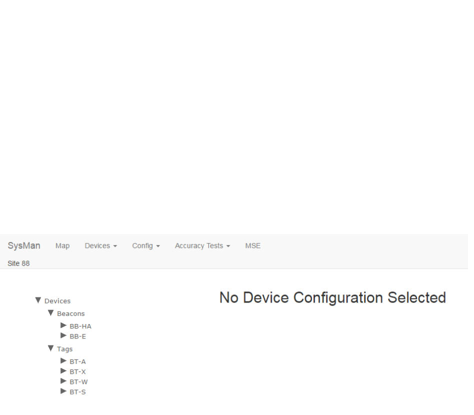
6.1 Device Config
The Device Config tab allows you to set configuration options for all devices (Tags and
Beacons) in System Manager.
Click the Device Config tab to display the following screen:
6.1.1 Configuring Beacons
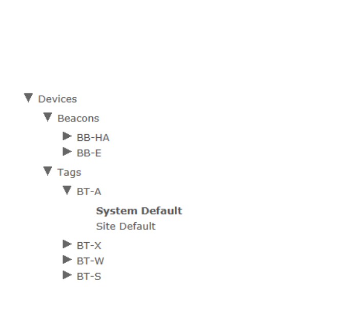
1. From the devices list on the left, drill down to find the Beacon type whose
configuration you want to change or update, then select the configuration
beneath it.
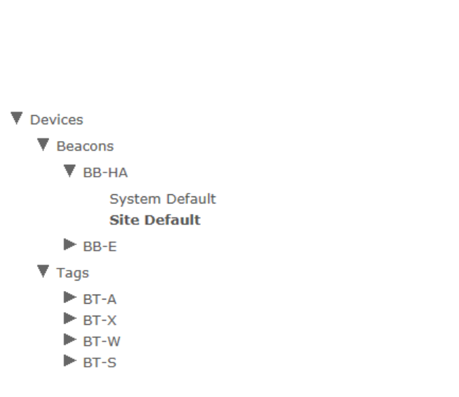
56
System Manager User Guide |
System Manager 2.0
The selected configuration information displays to the right.
57
System Manager User Guide |
System Manager 2.0
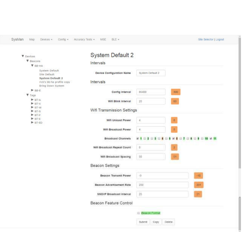
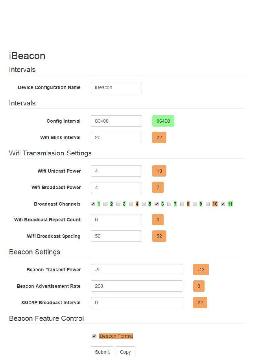
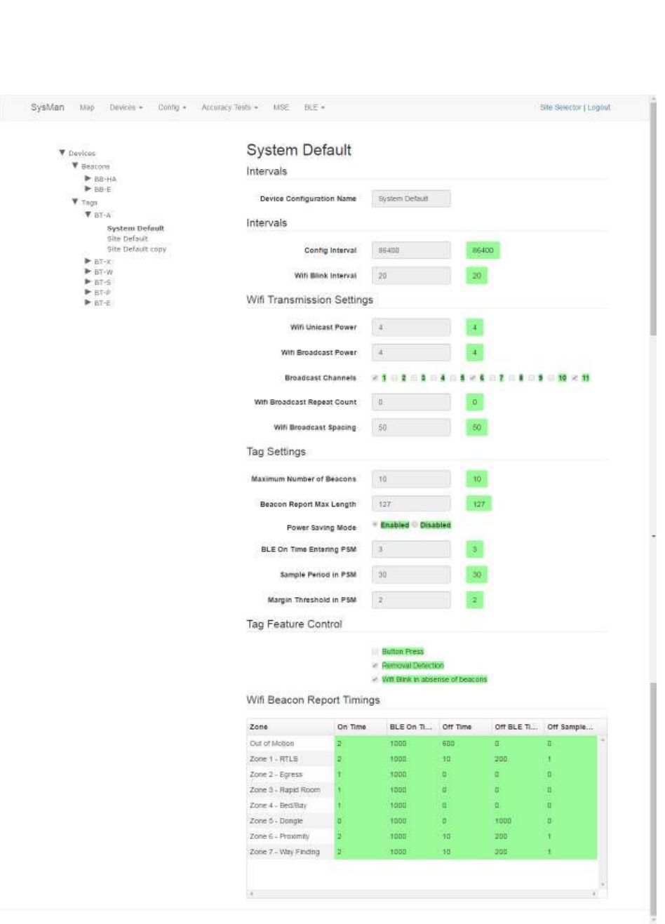
2. Edit each desired field or checkbox to the configuration settings desired.
o Device Configuration Name: The name of the configuration as it will
appear in the explorer pane.
o Config Interval: The time, in seconds, between each time the Beacon will
send out a signal to receive configuration information.
o Wifi Blink Interval: The time, in seconds, between each WiFi blink.
o Wifi Unicast Power: Absolute WiFi transmit power for connected
communication setting in integers from 4 (14.8dbm) to 15 (4dbm)
o Wifi Broadcast Power: Absolute WiFi transmit power for broadcast
communication setting in integers from 4 (14.8dbm) to 15 (4dbm)

58
System Manager User Guide |
System Manager 2.0
o Broadcast Channels: Which WiFi channels the Beacon will broadcast on;
1-3 channels can be selected
o Wifi Broadcast Repeat Count: How many times to repeat the same
messages
o Wifi Broadcast Spacing: The time, in milliseconds, between WiFI
broadcast repeats
o iBeacon UUID: The Awarepoint proximity unique ID to distinguish
Awarepoint iBeacons from other iBeacons (fixed at hex F56D9233-9ADF-
48E2-902D-34A544DD1B82 in big-endian order)
o Beacon Transmit Power: Transmit power setting in integers from -21
(-20.31dbm) to 5 (4.13dbm)
o Beacon Advertisement Rate: The time, in milliseconds, between Beacon
advertisements
o SSID/IP Broadcast Interval: The time, in seconds, between each
Broadcast Site ID
o iBeacon Format: When checked, Beacon sends messages in iBeacon
format
NOTE: Unless there is a specific reason to make changes, such as accuracy
testing, the default numbers for these fields should be sufficient.
3. Click Submit to apply any changes made.
Alternatively, click Cancel to cancel any changes made.
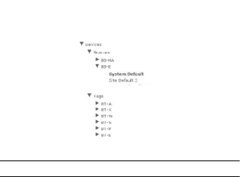
6.1.2 Configuring a Beacon as an iBeacon
For interacting with third party applications, it may be necessary to configure a Beacon
as an iBeacon. To do so, perform the following procedure.
1. From the devices list on the left, drill down to the BB-E Beacon type.
59
System Manager User Guide |
System Manager 2.0
1. Select a configuration beneath this type that can be copied.
NOTE: The System Default type cannot be copied, so select another type such
as Site Default.
2. Enter the settings for the iBeacon type as shown in the following figure.
60
System Manager User Guide |
System Manager 2.0
For accessing the Feature Control section, you will need to press Alt+O while
the cursor is in the Beacon Transmit Power input field.
The SSID/IP Broadcast Interval field must be 0.
The iBeacon Format check box must be selected.

61
System Manager User Guide |
System Manager 2.0
NOTE: You can choose your own Device Configuration Name; however, it is
helpful if iBeacon is in the name for identification purposes.
3. Batch create the beacon(s).
Refer to the Create section for this procedure.
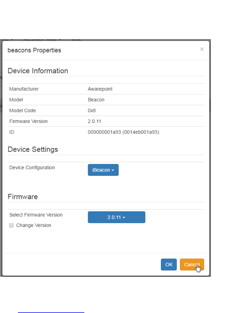
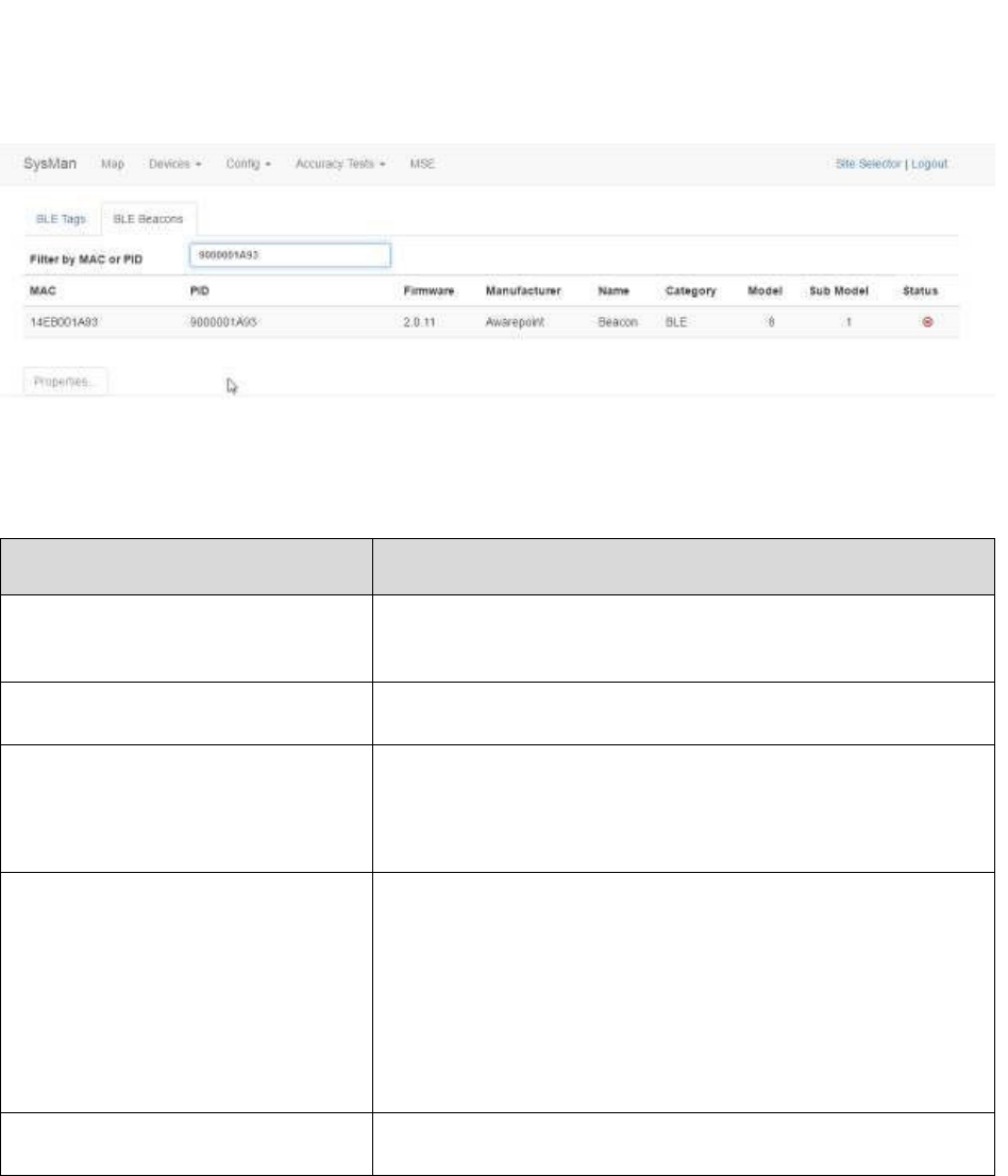
4. Navigate to the Device Management window (Devices > Device Management)
and select the BLE Beacons tab.
5. Locate and select the beacon(s) you want to configure in the iBeacon format and
click the Properties button.
6. Under Device Settings, select the new iBeacon format for the beacon(s) and
click OK.
62
System Manager User Guide |
System Manager 2.0
7. Provision the beacon(s) with a valid configuration using the Provisioning
application.
Refer to Provisioning Beacons for instructions on provisioning the beacon.
After the device has configured, the MAC address of the beacon(s) will show
along with the PID of the beacon(s) in the Device Management window.
63
System Manager User Guide |
System Manager 2.0
You can also use the Beacon Sniffer tool on the Awarepoint tablet to verify the
beacon(s) is sending messages as iBeacon.
6.1.2.1 Troubleshooting
Issue Solution
After power cycling the device no
LED lights can be seen on the
device.
Allow the device extra time and try again. If the issue persists,
you may need to RMA the device.
The device cannot be provisioned. Restart the tablet and try again. If the issue persists, RMA the
device.
No beacon configuration request
message appears in the log.
Check the following:
• Verify the parameters used in the provisioning app are
correct
• Verify the wireless network is functioning
Configuration request is rejected. Verify the following:
• The device firmware is available
• The network configuration in System Manager is
correct
• The device type of the beacon matches what you batch
created
• The appliance is correctly communication with the
NOC
No beacon can be seen in the
Beacon Sniffer app on the tablet.
Power cycle the device a few times with a longer waiting period
then repeat the provisioning process.
6.1.3 Configuring Tags
1. From the devices list on the left, drill down to find the Tag type whose
configuration you want to change or update, then select the configuration
beneath it.
64
System Manager User Guide |
System Manager 2.0
The selected configuration information displays to the right.
65
System Manager User Guide |
System Manager 2.0
2. Edit each desired field or checkbox to the configuration settings desired.

66
System Manager User Guide |
System Manager 2.0
o Device Configuration Name: The name of the configuration as it will
appear in the explorer pane.
o Config Interval: The time, in seconds, between each time the Tag will
send out a signal to receive configuration information.
o Wifi Blink Interval: The time, in seconds, between each WiFi blink.
o Wifi Unicast Power: Absolute WiFi transmit power for connected
communication setting in integers from 4 (14.8dbm) to 15 (4dbm)
o Wifi Broadcast Power: Absolute WiFi transmit power for broadcast
communication setting in integers from 4 (14.8dbm) to 15 (4dbm)
o Broadcast Channels: Which WiFi channels the Beacon will broadcast on;
1-3 channels can be selected
o Wifi Broadcast Repeat Count: How many times to repeat the same
messages
o Wifi Broadcast Spacing: The time, in milliseconds, between WiFI
broadcast repeats
o Maximum Number of Beacons: Maximum number of Beacons for a Tag
to report on, utilizing the strongest N beacons where N is the maximum
number
o Beacon Report Max Length: Maximum size, in bytes, of the Beacon
report length (max is 127)
o Power Saving Mode: Enabled by default to extend battery life
o BLE On Time Entering PSM: Length of time, in seconds, the Bluetooth
Low Energy (BLE) is on before entering Power Saving Mode (PSM)
o Sample Period in PSM: Length of time, in seconds, in PSM between
sending out WiFi reports
o Margin Threshold in PSM: The RSSI difference between the loudest and
second loudest RSSI before entering PSM
o Button Press: When checked, allows Tag to be disabled by button press
67
System Manager User Guide |
System Manager 2.0
o Removal Detection: When checked, sends a removal alert if Tag is
removed from asset
o Wifi Blink in absence of beacons: When checked, Tag sends out WiFi
blinks if no Beacon is detected
NOTE: Unless there is a specific reason to make changes, such as accuracy
testing, the default numbers for these fields should be sufficient.
3. Click Submit to apply any changes made.
Alternatively, click Cancel to cancel any changes made.
6.1.4 Creating a New Configuration
You create a new configuration by copying a previously existing one and renaming it,
then adjusting the configuration parameters as necessary.
1. In the explorer pane, drill down to the configuration that you want to copy and
select it.
2. At the bottom of the configuration settings pane, click the Copy button.
3. In the Device Configuration Name field, enter the name for the new
configuration.
4. Enter or edit the new configuration parameters.
5. Click Submit to save the changes and create your new configuration settings.
6.2 Network Config
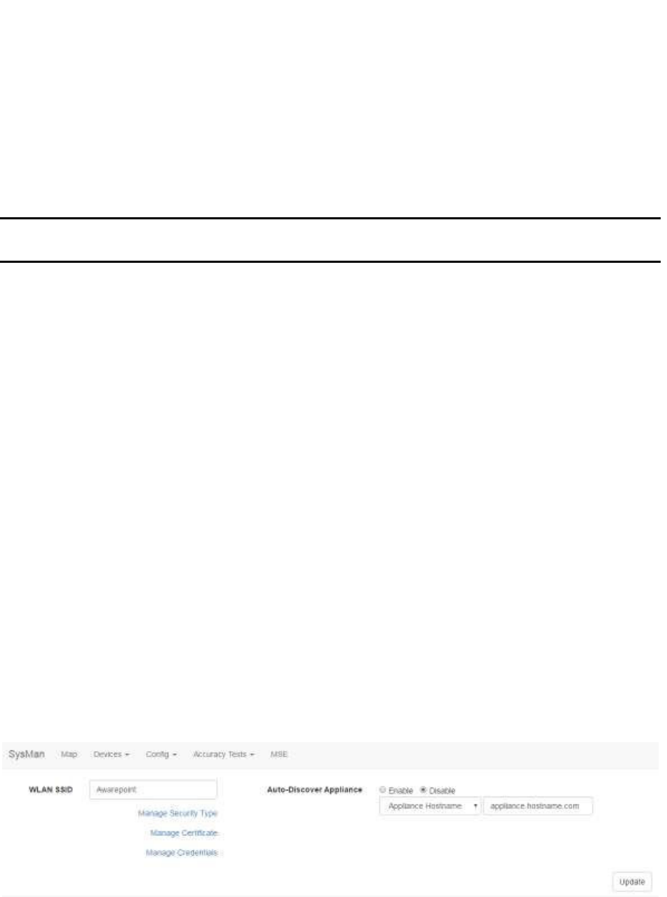
Clicking the Network Config tab displays the following screen:
Network configuration information for filling in the fields is gathered by the Project
Management team and given to the ASA team to be entered on site.
68
System Manager User Guide |
System Manager 2.0
6.2.1 Text Fields
• WLAN SSID – In this text field, enter the wireless LAN SSID of the network. This
is the SSID that will be used by Awarepoint devices to connect to the network.
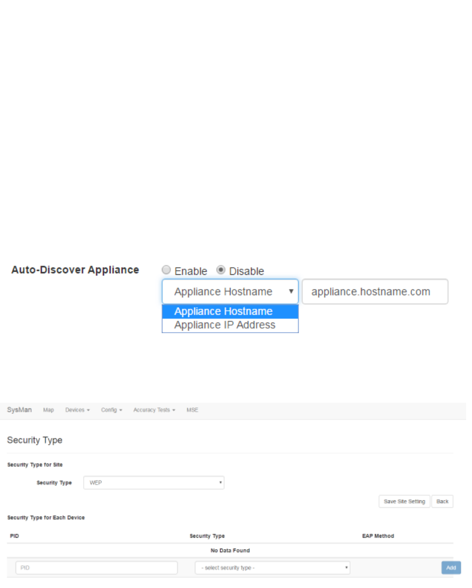
• Auto-Discover Appliance – Select the radio button to enable or disable the
auto-discovery feature.
From the first drop-down menu, select whether to search by hostname or IP
address.
In the text field, enter the appliance hostname or IP address in accordance with
the drop-down selection.
6.2.2 Manage Security Type
Click this link to display the Security Type window.
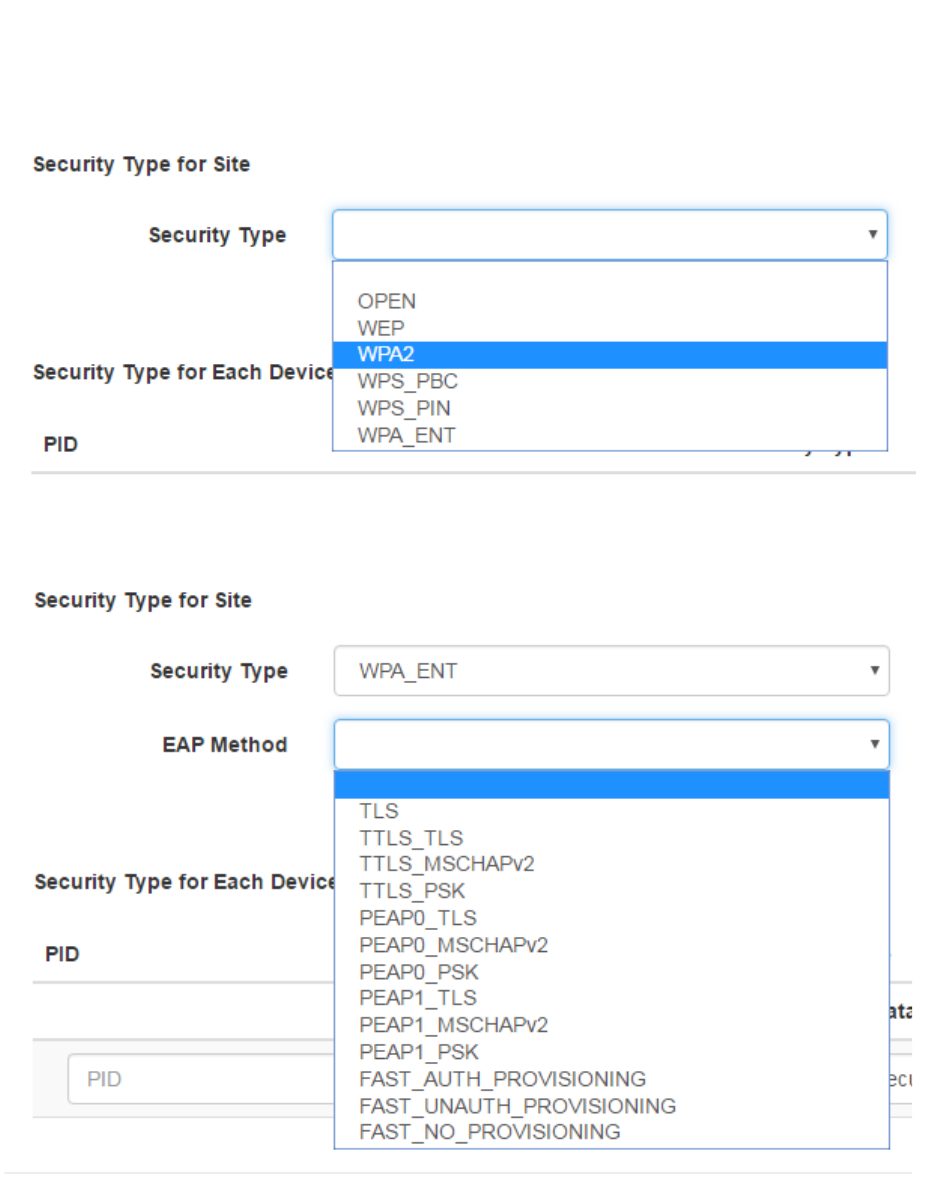
6.2.2.1 Changing the Site Security Type
Use the Security Type drop-down menu to select the security type (e.g., WPA2 or
WPA_ENT).
69
System Manager User Guide |
System Manager 2.0
If an EAP method is required for your chosen security type, a second drop-down
displays for the EAP Method.
Click Save Site Setting to save the changes.
6.2.2.2 Changing a Device’s Security Type
You can set a Tag or Beacon to have a different security type than the site’s security by
adding it to the Security Type for Each Device list.
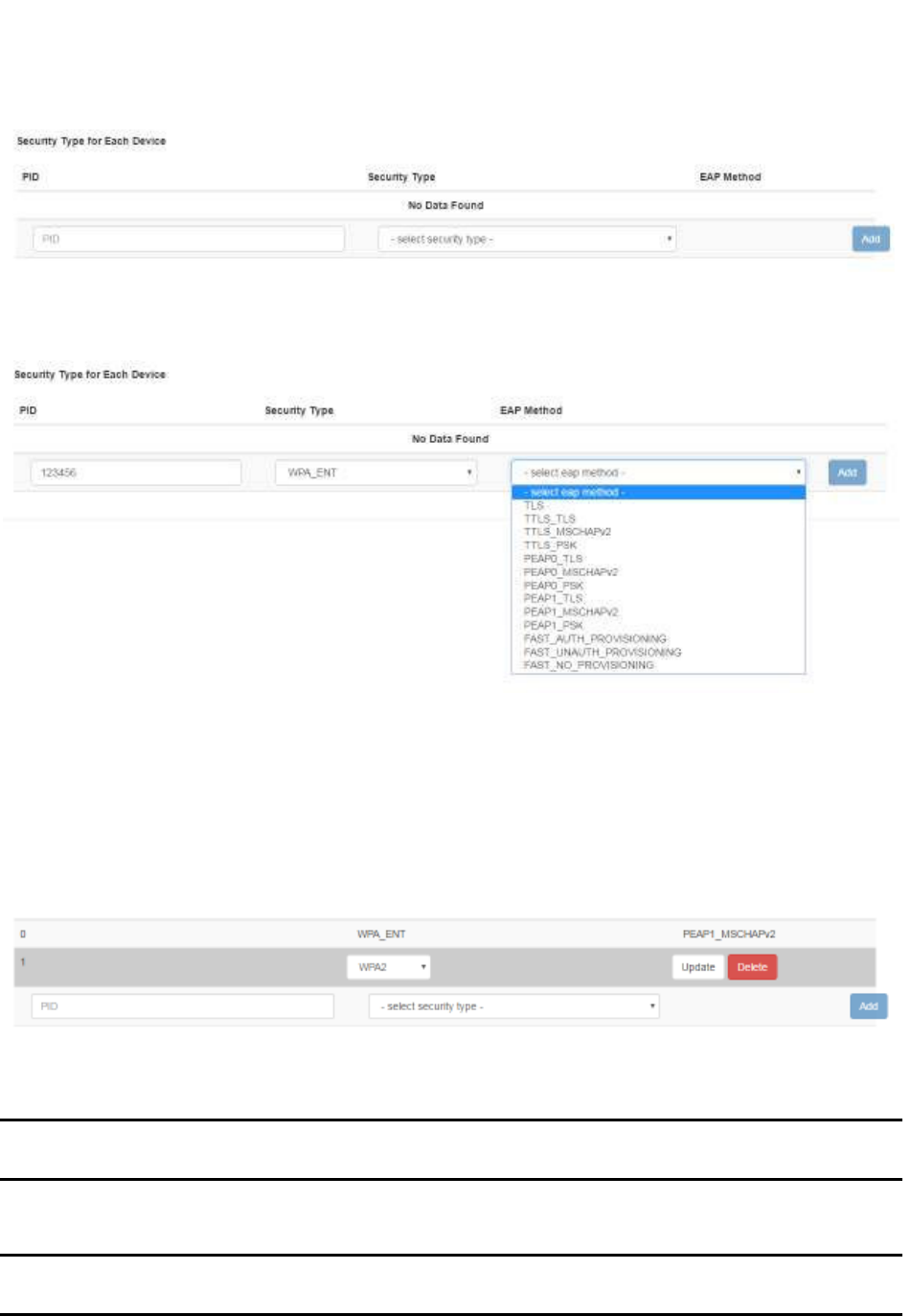
70
System Manager User Guide |
System Manager 2.0
For each device, enter the PID for the device, followed by the Security Type and, if
applicable, EAP Method.
After entering the information, click the Add button.
6.2.2.3 Updating or Deleting a Device’s Security Type
Once you have added an individual device with its own security type, that security type
can be changed or deleted as necessary.
Locate the device by PID in the list of devices and click it.
If you are updating the security type, use the drop-down menu to change the security
type and then click Update.
NOTE: If an EAP method is required, another drop-down menu will display for you
to enter the EAP method.
To delete the security type, click the Delete button.
NOTE: There is no confirmation dialog that displays when you delete a device
security type.
71
System Manager User Guide |
System Manager 2.0
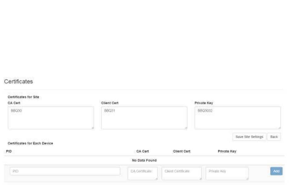
6.2.3 Manage Certificate
Click this link to display the Certificates window.
This window is divided into two parts:
• Certificates for Site
• Certificates for Each Device
6.2.3.1 Adding a Site Certificate
1. Copy the site certificate to your clipboard.
2. In the Certificates window in the Certificates for Site area, determine whether
the certificate is a CA Cert, a Client Cert, or a Private Key, then paste it into the
appropriate text field.
3. Click the Save Site Settings button.
6.2.3.2 Adding a Device Certificate
1. Copy the site certificate to your clipboard.
2. In the Certificates window in the Certificates for Each Device area, select the
device for which you have the certificate.
If the device you want is not listed, add it by entering the PID of the device in the
PID text field.
72
System Manager User Guide |
System Manager 2.0
3. Determine whether the certificate is a CA Cert, a Client Cert, or a Private Key,
then paste it into the appropriate text field.
4. Click the Add button.
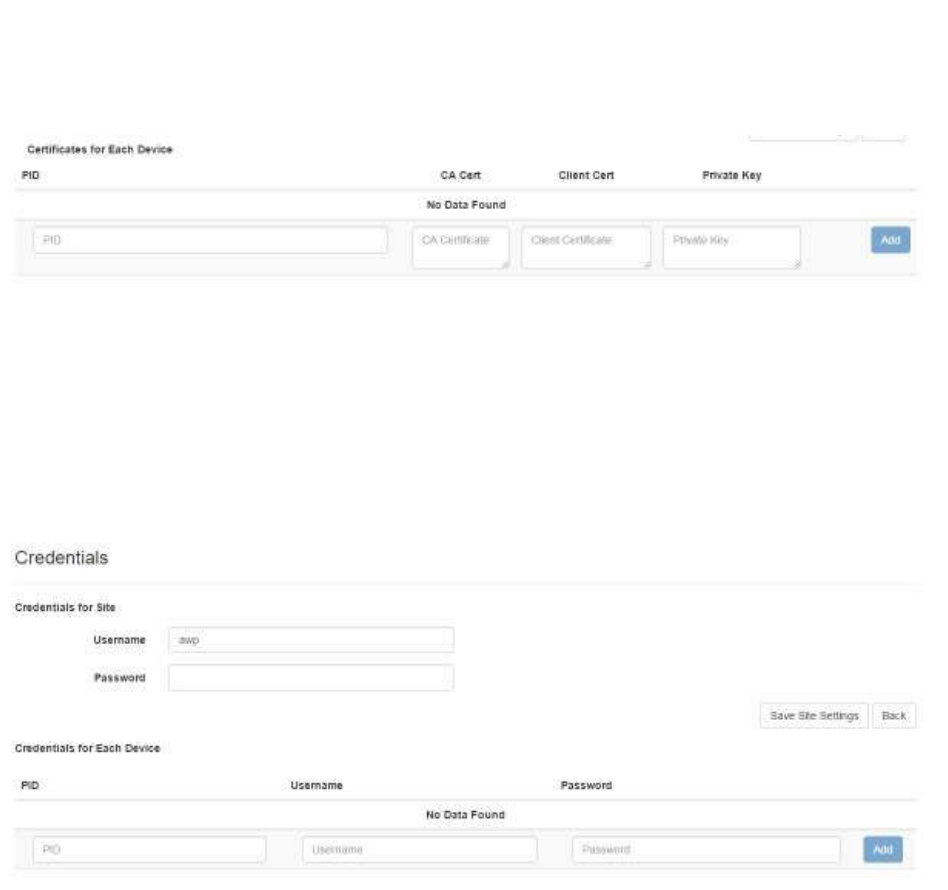
6.2.4 Manage Credentials
Click this link to display the Credentials window.
This window is divided into two parts:
• Credentials for Site
• Credentials for Each Device
For site credentials, in the Credentials for Site area enter the username and password
for connecting to the WLAN and click the Save Site Settings button.
For device credentials, in the Credentials for Each Device area enter the PID for each
device, followed by the username and password each device will use. You will need to
enter the username and password for each device that needs to use it.
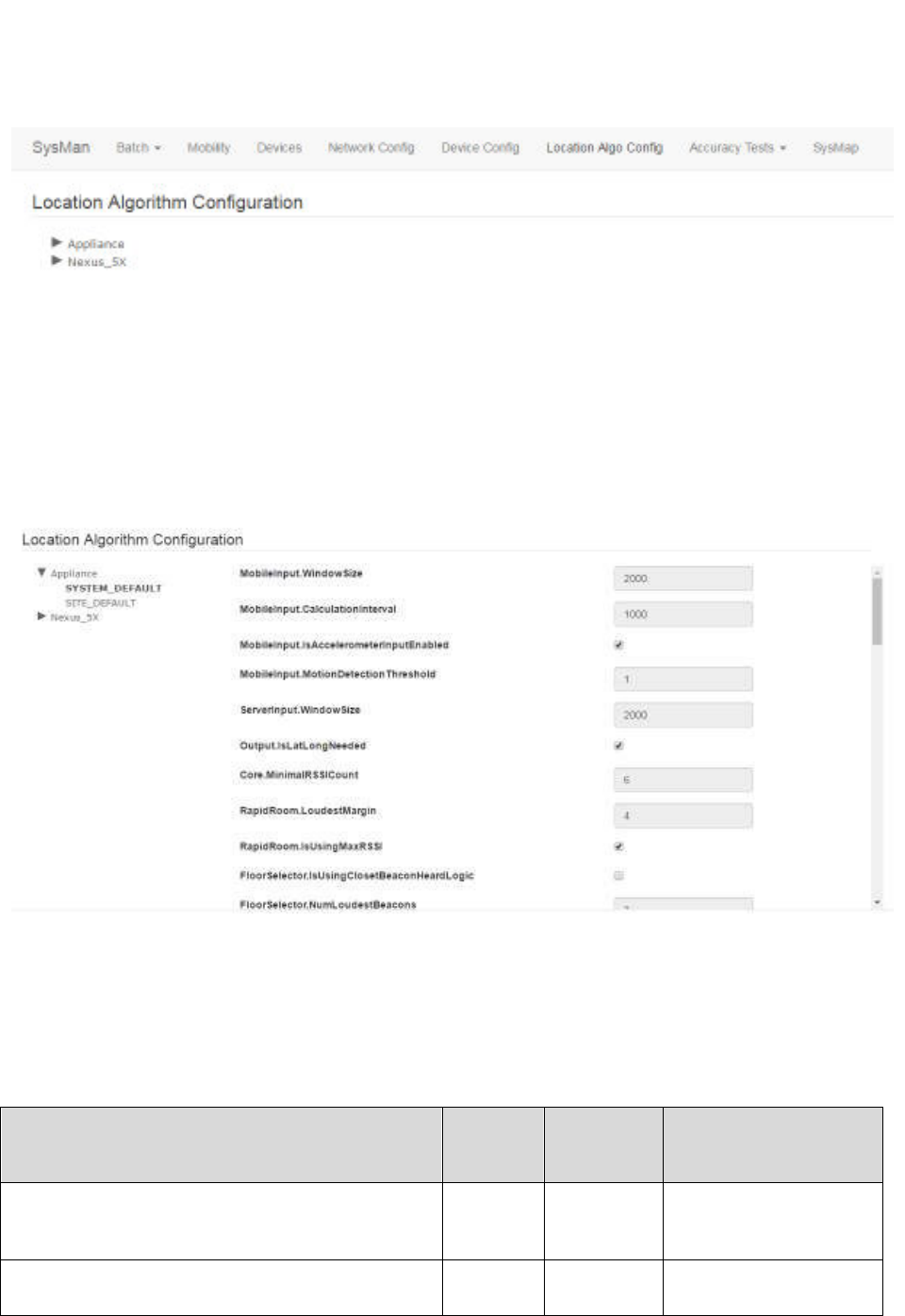
6.3 Location Algorithm Config
The Location Algorithm Config tab provides access to the location algorithm
configuration for the site.
73
System Manager User Guide |
System Manager 2.0
All Location Algorithm Configuration parent items that display are preloaded in System
Manager. These cannot be added to, edited, or deleted.
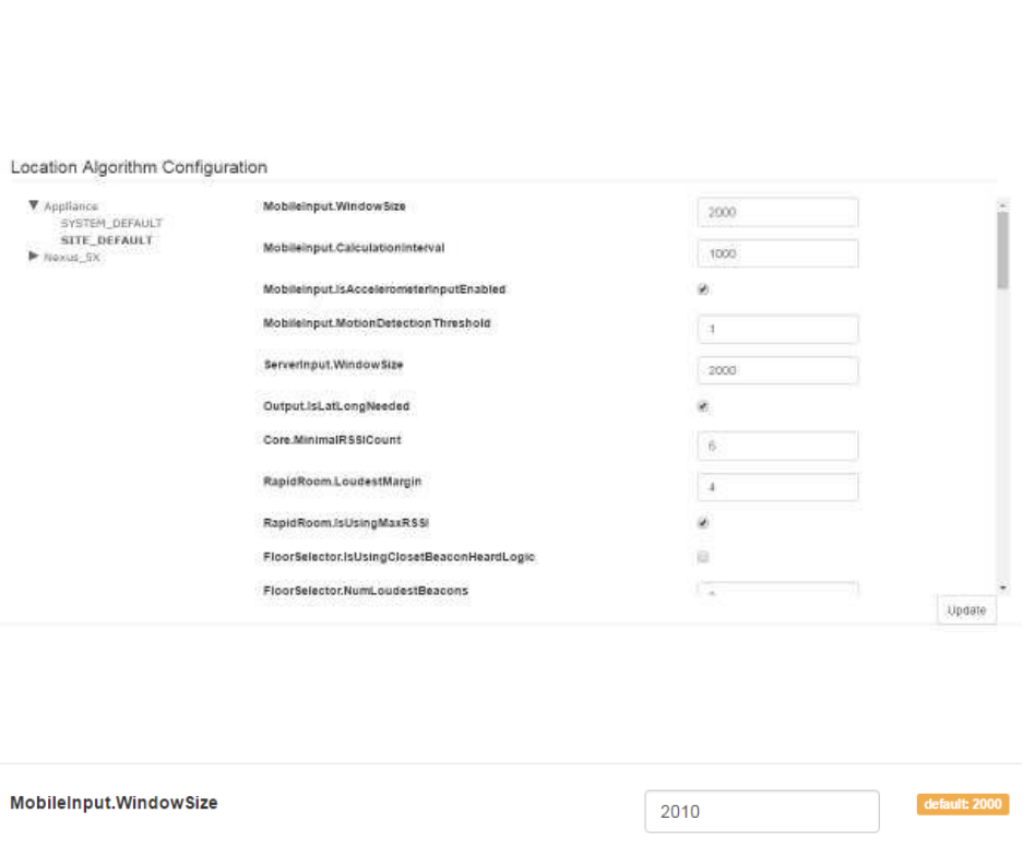
6.3.1 Viewing an Algorithm Configuration
Expand the list of configurations on the left and select a configuration to see its
configuration settings.
There are two configuration settings, SYSTEM_DEFAULT and SITE_DEFAULT. The
System Default configuration is preloaded with System Manager and cannot be
changed. The Site Default configuration is installed when a new site is first created.
These values can be changed.
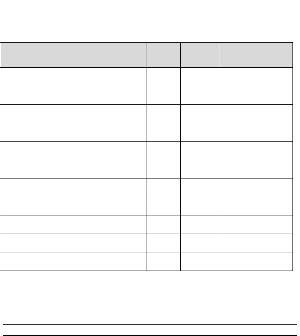
The following table provides an overview of the settings:
Parameter Type Default
Value
Note
MobileInput.WindowSize int 2000 Mobile calculation
window size in
milliseconds
MobileInput.CalculationInterval int 1000 Mobile calculation
interval in milliseconds

74
System Manager User Guide |
System Manager 2.0
Parameter Type Default
Value
Note
MobileInput.IsAccelerometerInputEnabled boolean TRUE Whether to use
accelerometer input or
in/out motion input from
the app
MobileInput.MotionDetectionThreshold double 1.0 Motion detection
threshold when using
accelerometer input
ServerInput.WindowSize int 2000 Server calculation
window size in
milliseconds
Output.IsLatLongNeeded boolean TRUE Whether there is
Lat/Long input to
generate lat/long output
Core.MinimalRSSICount int 6 Minimal number of
RSSIs required to
generate a new
location calculation
RapidRoom.LoudestMargin double 4.0 Loudness margin used
in Rapid Room
calculation
RapidRoom.IsUsingMaxRSSI boolean TRUE Whether to use
maximal RSSI in Rapid
Room calculation
FloorSelector.IsUsingClosetBeaconHeardLogic boolean FALSE Whether to use the
closet beacon heard
logic in Floor Selection
FloorSelector.NumLoudestBeacons int 3 Number of loudest
beacons used in the
Floor Selection
Rtls.isStrongBeaconEnabled boolean FALSE Whether to enable
strongest beacon
calculation in RTLS
Rtls.strongBeaconRSSIThreshold double -45.0 The beacon threshold
when strongest beacon
is enabled
Rtls.rssiDistanceConverter.roomPathLossExpone
nt
double 2.15 Path Loss Exponent
value for room
Rtls.rssiDistanceConverter.hallwayPathLossExpo
nent
double 2.7 Path Loss Exponent
value for hallway
Rtls.rssiDistanceConverter.openSpacePathLossE
xponent
double 1 Path Loss Exponent
value for open space
Rtls.rssiDistanceConverter.defaultPathLossExpon
ent
double 2.425 Default Path Loss
Exponent value

75
System Manager User Guide |
System Manager 2.0
Parameter Type Default
Value
Note
WayFinding.loudestMargin double 5.0 Loudness margin used
in Way Finding
Calm.FloorSelector.inMotionWeight double 0.34 Floor Selection in
motion weight in CALM
Calm.FloorSelector.outMotionWeight double 0.1 Floor Selection out
motion weight in CALM
Calm.AssetRTLSInMotionWeight double 1.0 Asset RTLS in motion
weight in CALM
Calm.AssetRTLSOutMotionWeight double 0.0 Asset RTLS out motion
weight in CALM
Calm.AssetRapidRoomInMotionWeight double 1.0 Asset Rapid Room in
motion weight in CALM
Calm.AssetRapidRoomOutMotionWeight double 0.0 Asset Rapid Room out
motion weight in CALM
Calm.AssetEgressInMotionWeight double 1.0 Asset Egress in motion
weight in CALM
Calm.AssetEgressOutMotionWeight double 0.0 Asset Egress out
motion weight in CALM
Calm.AssetBedBayInMotionWeight double 1.0 Asset Bed/Bay in
motion weight in CALM
Calm.AssetBedBayOutMotionWeight double 0.0 Asset Bed/Bay out
motion weight in CALM
Calm.PatientRTLSInMotionWeight double 1.0 Patient RTLS in motion
weight in CALM
Calm.patientRTLSOutMotionWeight double 0.0 Patient RTLS out
motion weight in CALM
Calm.patientRapidRoomInMotionWeight double 1.0 Patient Rapid Room in
motion weight in CALM
Calm.patientRapidRoomOutMotionWeight double 0.0 Patient Rapid Room
out motion weight in
CALM
Calm.patientEgressInMotionWeight double 1.0 Patient Egress in
motion weight in CALM
Calm.patientEgressOutMotionWeight double 0.0 Patient Egress out
motion weight in CALM
Calm.patientBedBayInMotionWeight double 1.0 Patient Bed/Bay in
motion weight in CALM
Calm.patientBedBayOutMotionWeight double 0.0 Patient Bed/Bay out
motion weight in CALM
76
System Manager User Guide |
System Manager 2.0
Parameter Type Default
Value
Note
Calm.staffRTLSInMotionWeight double 1.0 Staff RTLS in motion
weight in CALM
Calm.staffRTLSOutMotionWeight double 0.0 Staff RTLS out motion
weight in CALM
Calm.staffRapidRoomInMotionWeight double 1.0 Staff Rapid Room in
motion weight in CALM
Calm.staffRapidRoomOutMotionWeight double 0.0 Staff Rapid Room out
motion weight in CALM
Calm.staffEgressInMotionWeight double 1.0 Staff Egress in motion
weight in CALM
Calm.staffEgressOutMotionWeight double 0.0 Staff Egress out motion
weight in CALM
Calm.staffBedBayInMotionWeight double 1.0 Staff Bed/Bay in motion
weight in CALM
Calm.staffBedBayOutMotionWeight double 0.0 Staff Bed/Bay out
motion weight in CALM
Calm.wayFindingInMotionWeight double 1.0 Way Finding in motion
weight in CALM
Calm.wayFindingOutMotionWeight double 0.0 Way Finding out motion
weight in CALM
Log.logLevel int 0 Log level (0:info
1:debug)
6.3.2 Editing an Algorithm Configuration
From the list of configurations on the left, drill down to the configuration you want to edit
and select it.
NOTE: The SYSTEM_DEFAULT configuration cannot be edited.
77
System Manager User Guide |
System Manager 2.0
All fields and check boxes can be edited.
Once you change a value in the field, the default displays to the right.
Once you have completed your edits, click the Update button on the bottom right to
apply them.
78
System Manager User Guide |
System Manager 2.0
7 Accuracy Tests Tab
The Accuracy Tests tab provides four drop-down options for selection. They are:
• Plans
• Distance Tests
• Room Tests
• Runs
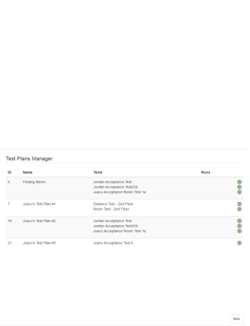
7.1 Accuracy Test Plans
Select Accuracy Tests -> Plans to display the Test Plans Manager window.
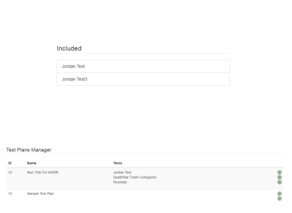
If any test plans have been created, they will display in this window. Test plans in the
window display:
• ID – Test plan ID number, automatically assigned by System Manager as the test
plan is created
79
System Manager User Guide |
System Manager 2.0
• Name – The Name of the test plan
• Tests – Any tests (distance and/or room tests) that have been grouped into the
plan
• Runs – The number of times the test has been run
• Green arrows allowing you to run the test they are next to
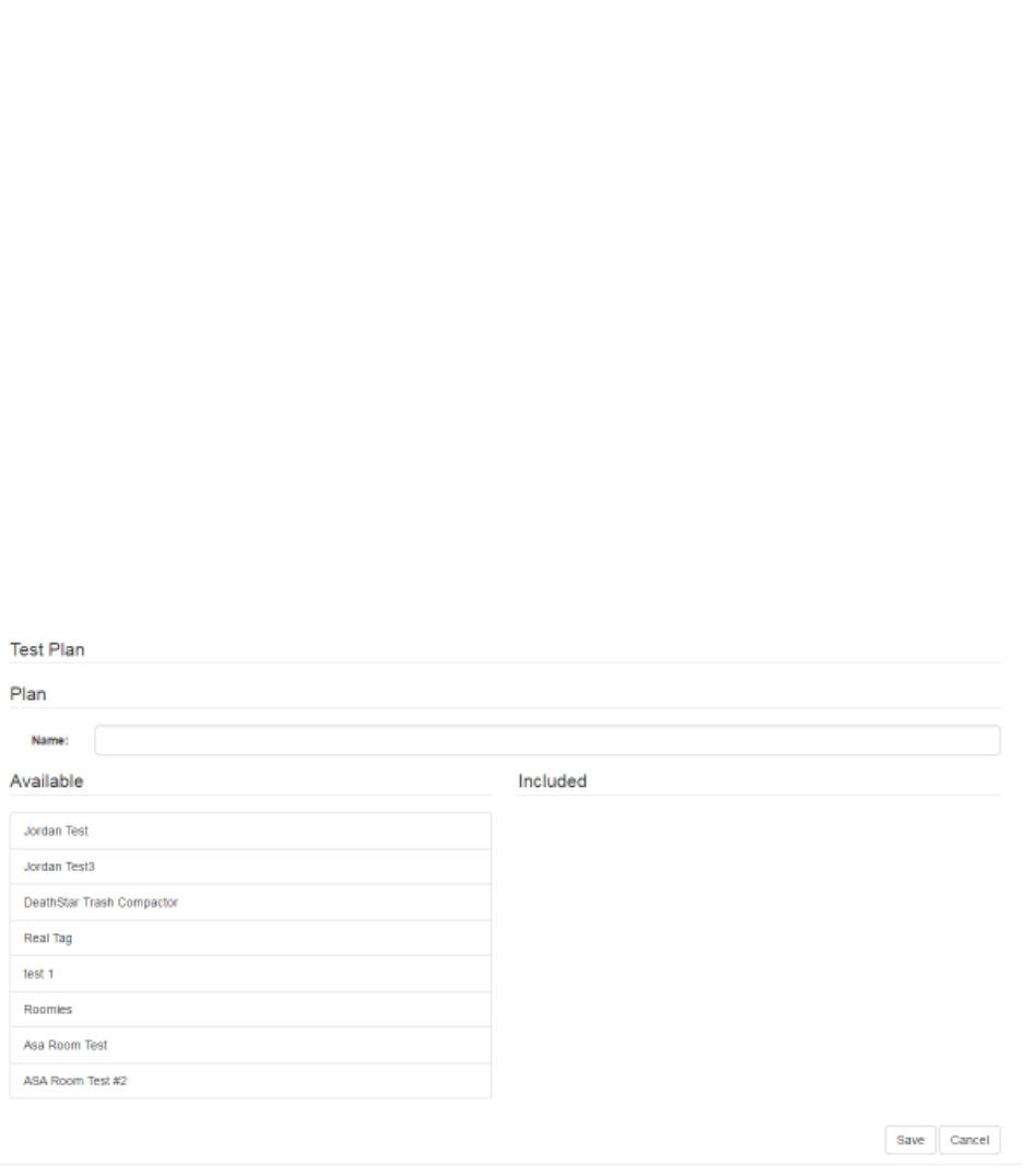
7.1.1 Creating a New Test Plan
1. From the Test Plans Manager window, click the New button in the bottom right
corner.
The Plan window displays.
2. In the Name text field, enter a name for the Test Plan.
3. From the Available list on the left, single click the test you want to make part of
your test plan.
Click each test you want to select.
Selected tests display in the Included list.
80
System Manager User Guide |
System Manager 2.0
4. When done selecting tests, click the Save button in the bottom right corner.
The new Test Plan now displays in the Test Plans Manager window.
7.1.2 Updating a Test Plan
1. From the Test Plans Manager window, single click the Test Plan you want to
update.
The buttons on the bottom right change to Clone, Update, and Delete.
2. Click the Update button.
The Plan window displays.
3. If necessary, change the name of the Test Plan.
4. If necessary, add or remove tests from the Test Plan.
To add a test, select it by clicking once on it from the Available list. The added
test will move to the Included list.
To remove a test, select it by clicking once on it from the Included list. The
removed test moves to the Available list.
5. When done making your changes, click the Save button in the bottom right
corner.
81
System Manager User Guide |
System Manager 2.0
7.1.3 Cloning a Test Plan
If an existing Test Plan is substantially similar to one you want to create, you can save
time by cloning that Test Plan.
1. From the Test Plans Manager window, single click the Test Plan you want to
update.
The buttons on the bottom right change to Clone, Update, and Delete.
2. Click the Clone button.
The Plan window displays.
3. In the Name field, enter a new name for the cloned test plan.
4. Add or remove tests, as needed.
5. Click the Save button to save the cloned Test Plan.
7.1.4 Deleting a Test Plan
Deleting a Test Plan does not delete any of the included tests nor any of the test run
data.
1. From the Test Plans Manager window, single click the Test Plan you want to
update.
The buttons on the bottom right change to Clone, Update, and Delete.
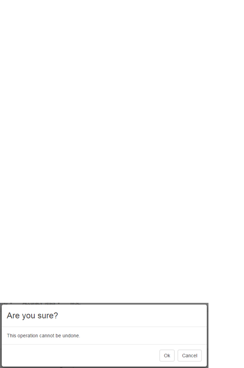
2. Click the Delete button.
A confirmation dialog displays.
3. Click OK to delete the Test Plan.
82
System Manager User Guide |
System Manager 2.0
7.2 Distance Tests
Distance tests are conducted to determine the accuracy of the Awarepoint system. A
Tag is placed on the map at a specified location and then the test is run. After the test,
results show the Tag’s position on the map as determined by its reports from the
Beacons it heard and their relative signal strength indicator (RSSI).
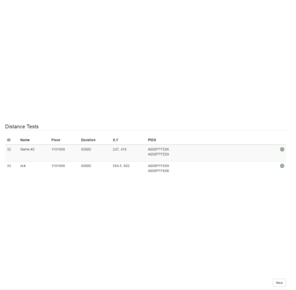
Select the Accuracy Tests -> Distance Tests link to display the Distance Tests
window.
Any Distance Tests that have already been created display in this window. Each
Distance Test displays:
• ID – A sequence number generated by System Manager to identify separate
tests
• Name – The name given to the test when it was created
• Floor – The floor ID as identified by System Manager
• Duration – The length, in milliseconds, of the Distance Test
• X,Y – The coordinates on the floor map as determined by System Manager
where the marker was placed
• PIDS – The Product ID numbers of all Tags that were part of the test
83
System Manager User Guide |
System Manager 2.0
• Green arrow – Runs the Distance Test
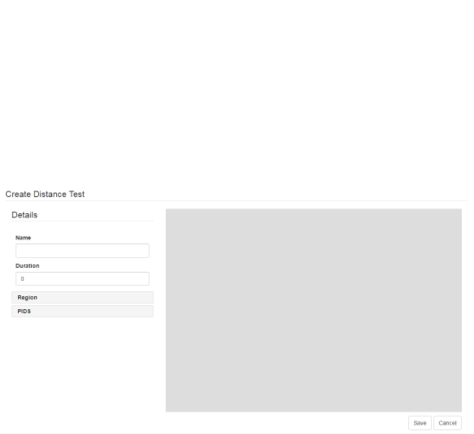
7.2.1 Creating a New Distance Test
1. From the Distance Tests window, click the New button in the bottom right
corner.
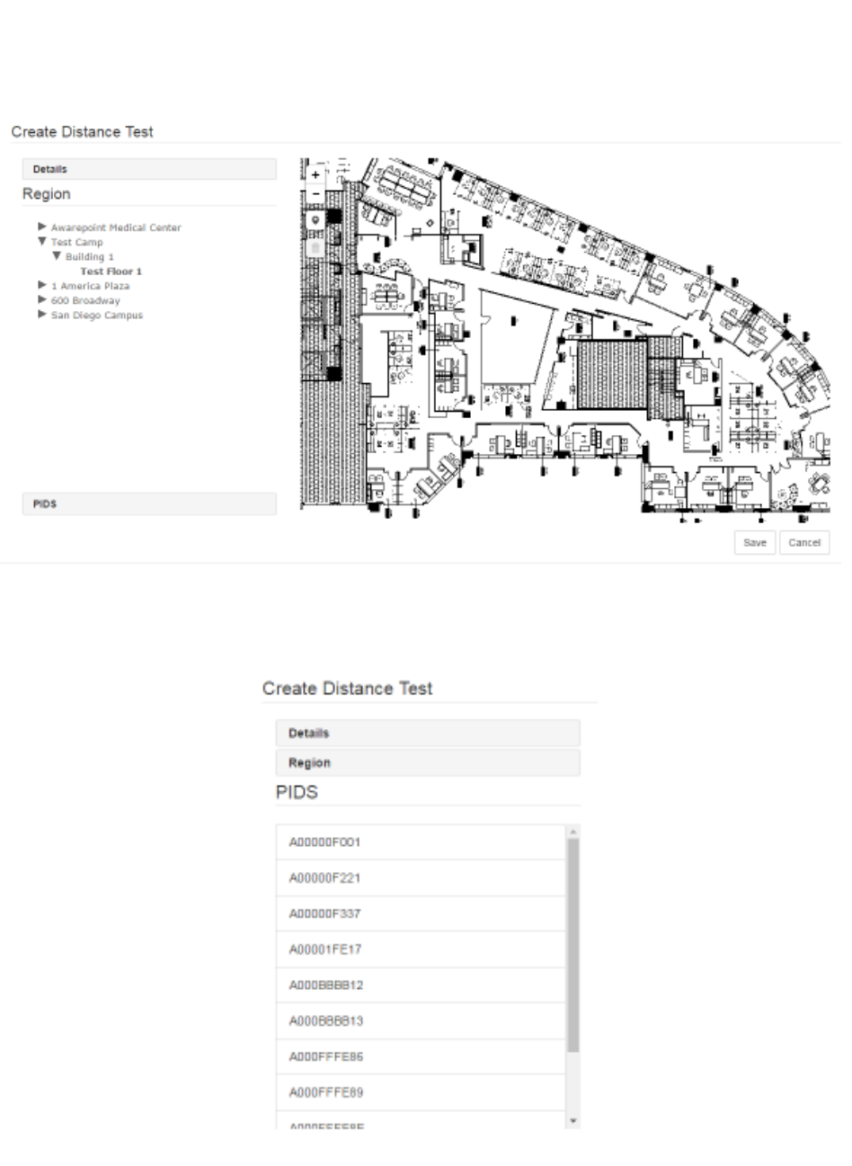
The Create Distance Test window displays.
2. In the Details area, enter a Name for the test and the Duration, in milliseconds.
3. Click the Region link.
4. In the Region area, drill down to find the floor on which you will be running the
Distance Test and select it.
The selected floor will display as bold in the list.
84
System Manager User Guide |
System Manager 2.0
5. Click the PIDS link.
A list of available Tags displays.
6. Select the PID of all Tags that will be used in the test.
Click a Tag PID to select it. You can select multiple PIDs by clicking them.
85
System Manager User Guide |
System Manager 2.0
To de-select a Tag, click it again.
NOTE: Only Tags that have been batch created and are not assigned display as
available for selection.
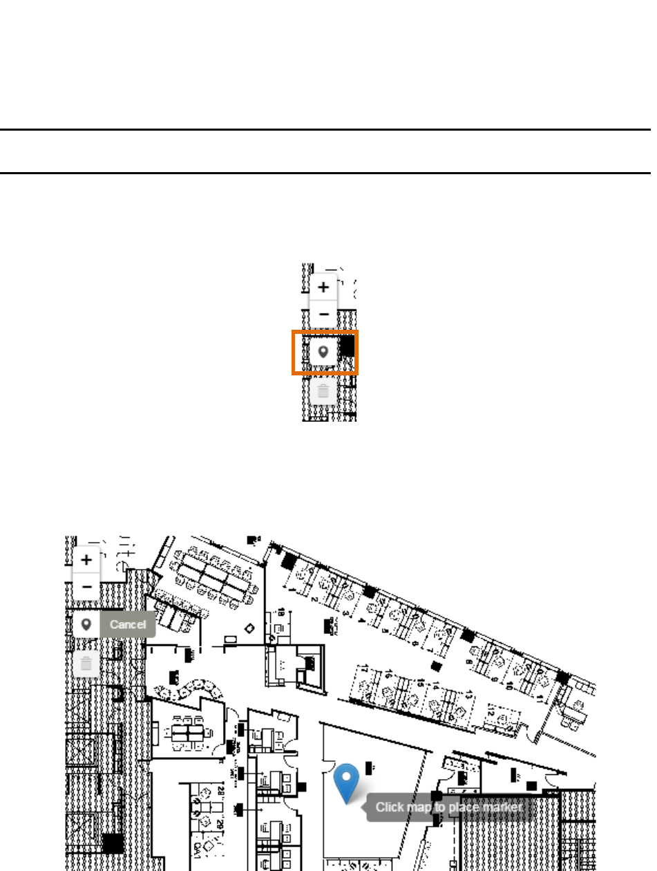
7. On the map, click the Draw a marker icon to place a marker on the map for the
location of the selected Tag(s).
8. Drag the marker to the place on the map and click once to place it.
You can scroll the mouse wheel to increase or decrease the size of the map as
well as click and drag the map without placing the marker.
9. Click Save to save the test.
The new test displays in the Distance Tests window and can be run by clicking
the green arrow next to it.

86
System Manager User Guide |
System Manager 2.0
7.2.2 Updating a Distance Test
If a Distance Test needs to be edited, such as a change to a location or the use of
different Tags, that is done through the update process.
1. In the Distance Tests window, click the Distance Test you want to edit.
2. In the lower right corner, click the Update button.
The Update Distance Test window displays.
3. As needed, edit the Name and Duration of the test.
4. Click the Region link and select a different floor, if necessary.
5. Click the PIDS link and select or deselect Tags, as necessary.
87
System Manager User Guide |
System Manager 2.0
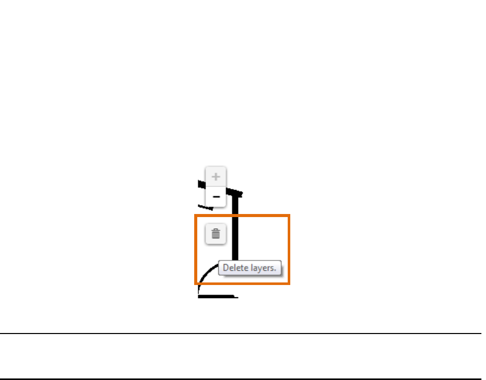
6. To remove a marker, click the Delete layers icon and then click the marker icon
to be deleted.
If there are multiple markers, you must click the Delete layers icon once for each
marker you want to remove.
7. After making all changes necessary, click Save to update the Distance Test.
NOTE: Updating a Distance Test does not erase the test’s historical runs. The
data from previous test runs, if applicable, will display along with any new
data.
7.2.3 Cloning a Distance Test
Cloning a test is done to create a test substantially similar to one already in existence
but without deleting one or creating a new one from scratch. This is especially useful
for retaining historical test run data but also for tests that may be run on the same floor
with the same parameters.
1. From the Distance Tests window, select the test you want to clone then click the
Clone button in the lower right corner.
The Update Distance Test window displays.
2. Enter a new name for the cloned test.
3. If necessary, enter a new duration.
4. Click the Regions link and select a new floor, if necessary.
5. Click the PIDS link and select the new Tags, if necessary.
6. If necessary, use the Delete layers icon to remove the current marker, then
place a new marker.
88
System Manager User Guide |
System Manager 2.0
7. Click Save.
7.2.4 Deleting a Distance Test
If a Distance Test is no longer needed, it can be deleted from the system. However,
any historical data from the test is also deleted, so a test should only be deleted when
necessary.
1. From the Distance Tests window, select the test you want to delete.
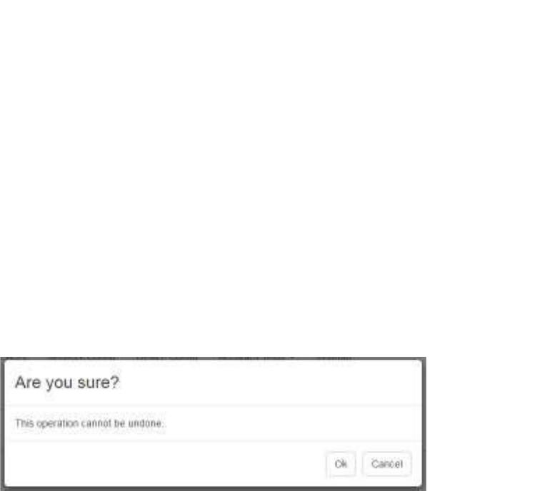
2. In the lower right corner, click the Delete button.
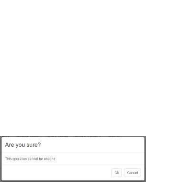
A confirmation dialog displays.
3. Click OK to delete the test and all historical test run data.
7.3 Room Tests
Room tests are conducted to determine the accuracy of the Awarepoint system in
identifying the location of a Tag as being in or out of a room. A Tag is placed on the
map at a specified location and then the test is run. After the test, results show the
Tag’s position on the map as determined by its reports from the Beacons it heard and
their relative signal strength indicator (RSSI).
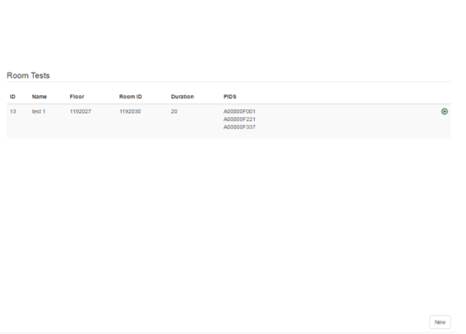
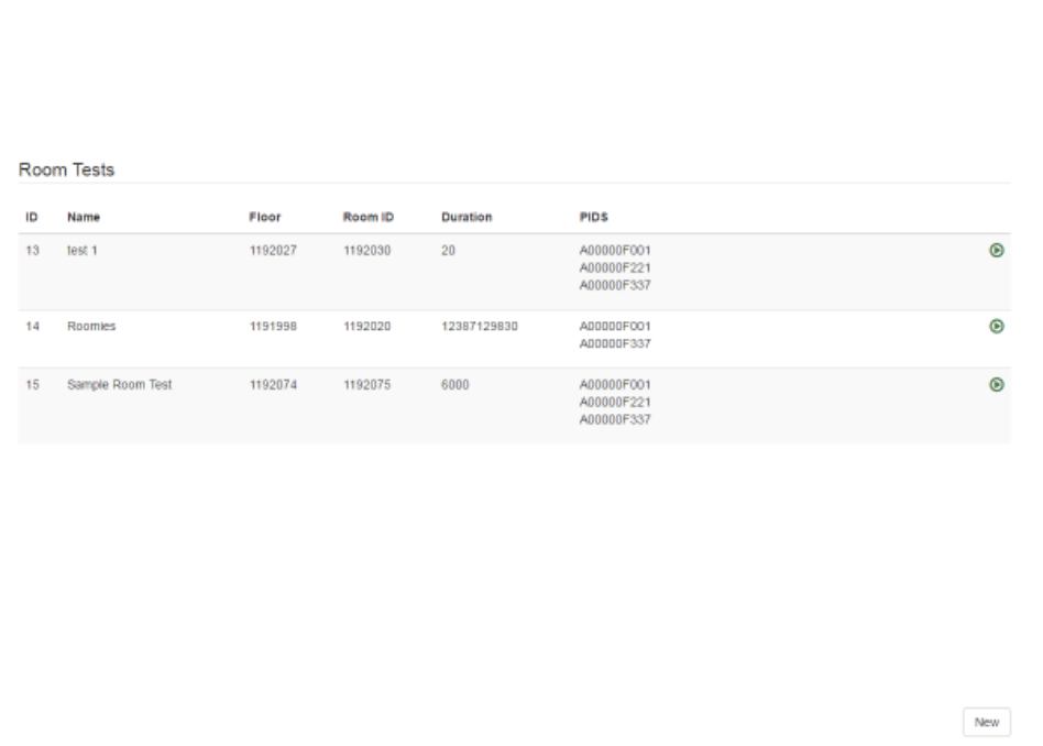
Selecting the Accuracy Tests -> Room Tests link displays the Room Tests window.
89
System Manager User Guide |
System Manager 2.0
Any Room Tests that have already been created display in this window. Each Room
Test displays:
• ID – A sequence number generated by System Manager to identify separate
tests
• Name – The name given to the test when it was created
• Floor – The floor ID as identified by System Manager
• Room ID – The room ID as identified by System Manager
• Duration – The length, in milliseconds, of the Distance Test
• PIDS – The Product ID numbers of all Tags that were part of the test
• Green arrow – Runs the Room Test
7.3.1 Creating a New Room Test
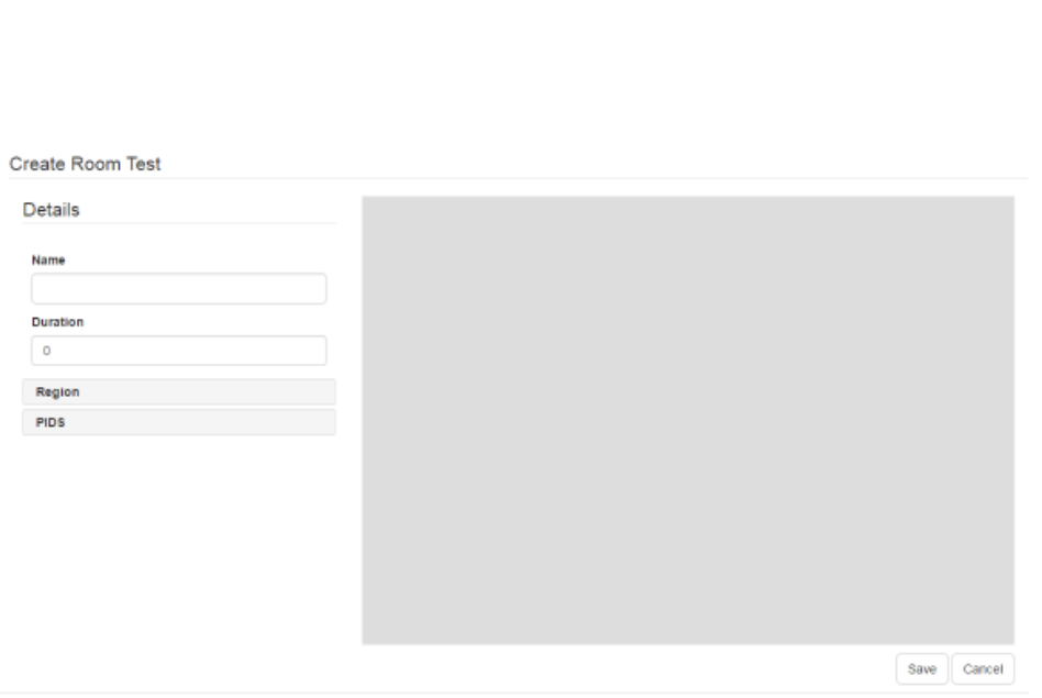
1. From the Room Tests window, click the New button in the bottom right corner.
The Create Room Test window displays.
90
System Manager User Guide |
System Manager 2.0
2. In the Details area, enter a Name for the test and the Duration, in milliseconds.
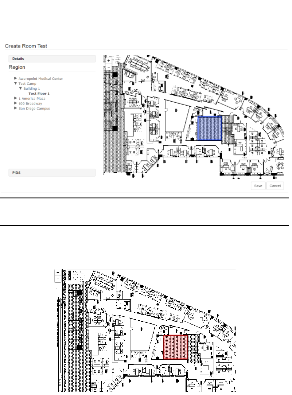
3. Click the Region link.
4. In the Region area, drill down to find the floor on which you will be running the
Room Test and select it.
The selected floor will display as bold in the list.
91
System Manager User Guide |
System Manager 2.0
NOTE: For a Room Test, defined rooms must already exist. If you have not yet
defined the room where the Tag(s) will be placed for the test, click Cancel
and follow the procedure in Defining an Area for creating a room.
5. Click the room to conduct the test.
The room region turns red when selected.
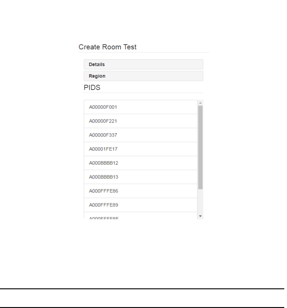
6. Click the PIDS link.
A list of available Tags displays.
92
System Manager User Guide |
System Manager 2.0
7. Select the PID of all Tags that will be used in the test.
Click a Tag PID to select it. You can select multiple PIDs by clicking them.
To de-select a Tag, click it again.
NOTE: Only Tags that have been batch created and are not assigned display as
available for selection.
8. Click Save to save the test.
The new test displays in the Room Tests window and can be run by clicking the
green arrow next to it.
93
System Manager User Guide |
System Manager 2.0
7.3.2 Updating a Room Test
If a Room Test needs to be edited, such as a change to a location or the use of different
Tags, that is done through the update process.
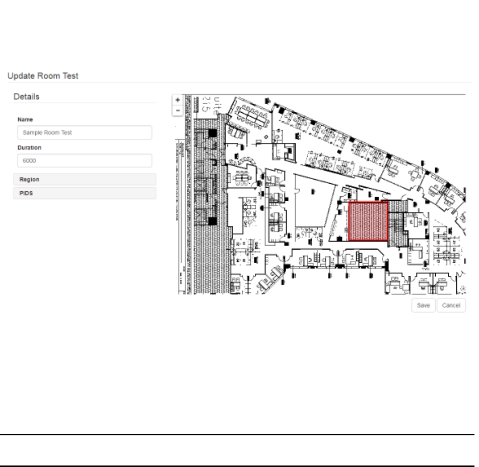
1. In the Room Tests window, click the Room Test you want to edit.
2. In the lower right corner, click the Update button.
The Update Room Test window displays.
94
System Manager User Guide |
System Manager 2.0
3. As needed, edit the Name and Duration of the test.
4. Click the Region link and select a different floor or room, if necessary.
5. Click the PIDS link and select or deselect Tags, as necessary.
6. After making all changes necessary, click Save to update the Room Test.
NOTE: Updating a Room Test does not erase the test’s historical runs. The data
from previous test runs, if applicable, will display along with any new data.
7.3.3 Cloning a Room Test
Cloning a test is done to create a test substantially similar to one already in existence
but without deleting one or creating a new one from scratch. This is especially useful
for retaining historical test run data but also for tests that may be run on the same floor
with the same parameters.
1. From the Room Tests window, select the test you want to clone then click the
Clone button in the lower right corner.
The Update Room Test window displays.
2. Enter a new name for the cloned test.
3. If necessary, enter a new duration.
4. Click the Regions link and select a new floor or room, if necessary.
95
System Manager User Guide |
System Manager 2.0
5. Click the PIDS link and select the new Tags, if necessary.
6. Click Save.
7.3.4 Deleting a Room Test
If a Room Test is no longer needed, it can be deleted from the system. However, any
historical data from the test is also deleted, so a test should only be deleted when
necessary.
1. From the Room Tests window, select the test you want to delete.
2. In the lower right corner, click the Delete button.
A confirmation dialog displays.
3. Click OK to delete the test and all historical test run data.
7.4 Test Runs
Test runs show the results of Distance and Room Tests individually.
Selecting the Accuracy Tests -> Runs link displays the Region window.
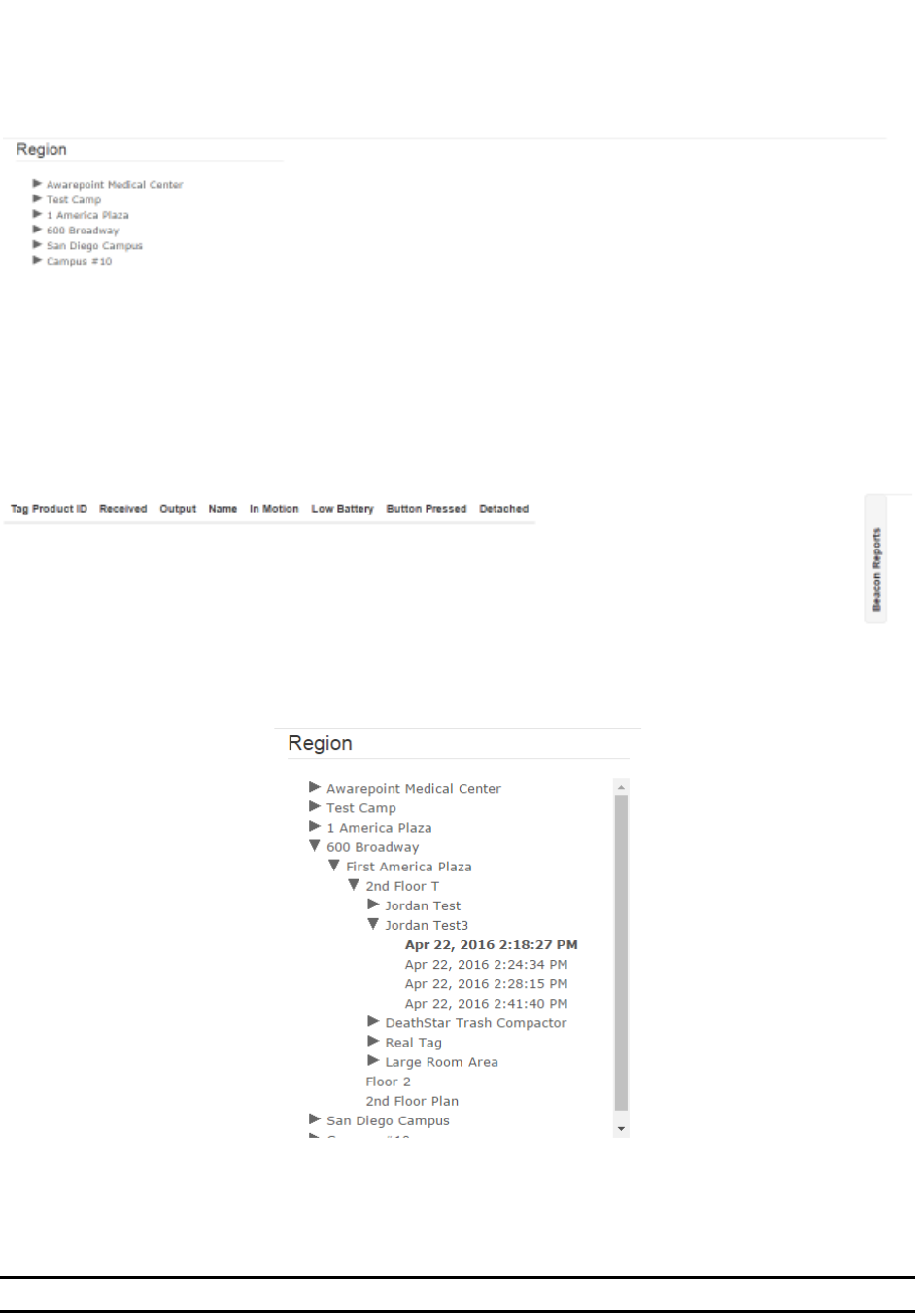
96
System Manager User Guide |
System Manager 2.0
To view the results of a test, drill down in the explorer pane to the test level, which is
below the floor level.
A selected test run becomes bold. If it was an Accuracy Test, the map area displays
the marker on the map. The results of the test run display below the map at the bottom
of the window.
NOTE: You may need to zoom in or out on the map to see it in its entirety.
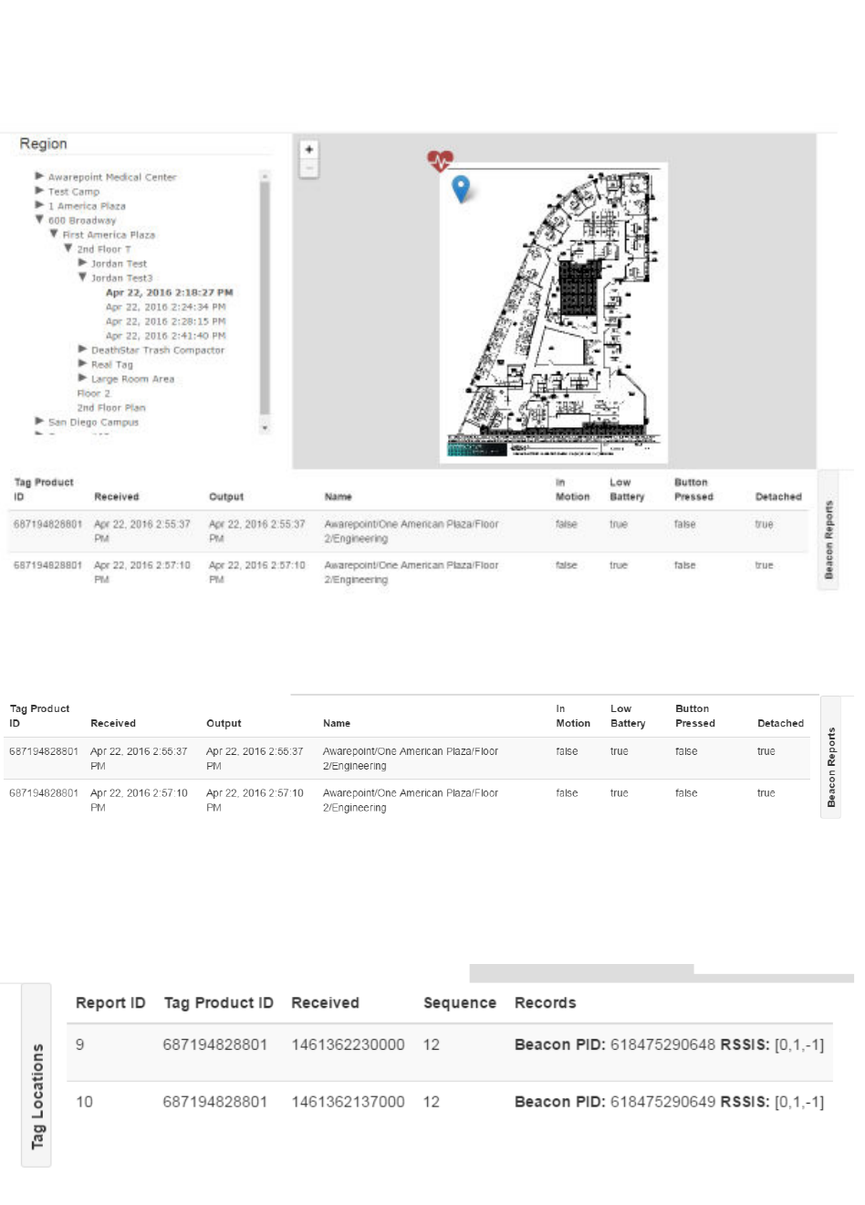
97
System Manager User Guide |
System Manager 2.0
The default information displayed below the map and explorer pane shows Tag
information for the selected test.
This information includes the Tag Product ID (PID), Name of the location where the test
was run, and other Tag information.
Clicking the Beacon Reports link displays Beacon information for the selected test.
This information contains the Tag PID, test run sequence, Beacon PID, and Beacon
signal strength.
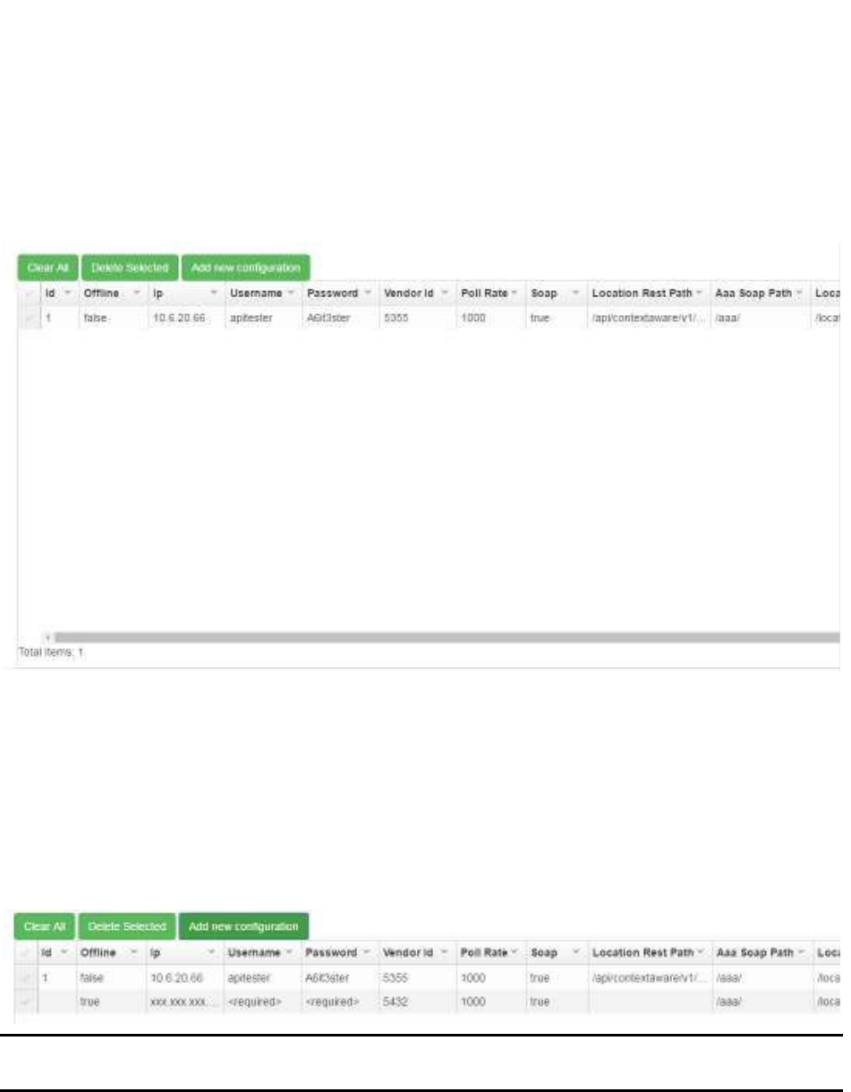
98
System Manager User Guide |
System Manager 2.0
8 MSE Tab
Click the MSE tab to display the configuration information for connecting to the Mobility
Services Engine (MSE).
The configuration settings in this screen allow the Awareness server to connect to the
MSE and retrieve information from Beacons on the network, such as Beacon reports
and broadcast status messages.
8.1 Creating a New Configuration
1. Click the Add new configuration button.
A new row appears in the configuration list.
NOTE: The ID of the configuration is automatically set by the system and appears
once you start entering information.
2. Double-click a field to enter information in it.
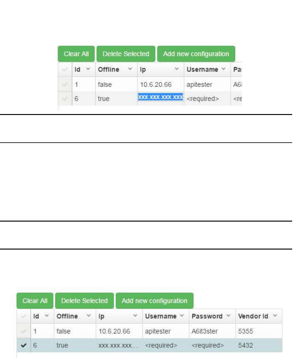
99
System Manager User Guide |
System Manager 2.0
NOTE: The Offline field displays as a check box when double-clicked. A check
indicates true and unchecked indicates false. This field should be set to
false for the configuration to take effect.
After entering all necessary information, the configuration is set. There is no
need to save or update it.
8.2 Editing an Existing Configuration
To edit an existing configuration, double-click the field you want to change and enter the
new information. Once you click away from the field, the new information will be
automatically saved.
NOTE: There is no limit to the number of configurations that can be present in this
list. Before editing a configuration, it may be better to create a new one
and set the configuration no longer needed to offline.
8.3 Deleting a Configuration
1. Click the checkbox to the left of the ID number.
You can select multiple configurations at once.
Clicking the checkmark again clears it. Click Clear All to clear all selected
configurations.
2. Click the Delete Selected button.
The configuration is deleted.

100
System Manager User Guide |
System Manager 2.0
NOTE: There is no confirmation dialog to confirm the deletion of all selected
configurations, so be certain that all the selected configurations can be
deleted before doing so. Deleted configurations cannot be retrieved.
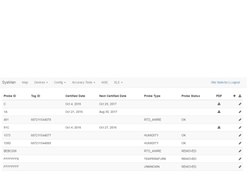
101
System Manager User Guide |
System Manager 2.0
9 BLE Tab
The BLE tab allows for the managing of BLE probes.
Select BLE -> Probe Certificates to display the Probe Certificates window.
If there are any probe certificates already loaded into the system, they will display in this
window. Probe certificates in the window display:
• Probe ID – The ID number of the probe associated with the certificate
• Tag ID – The ID number of the tag associated with the probe
• Certified Date – Date the probe was certified
• Next Certified Date – Date the probe will next need to be certified
• Probe Type – The type of probe
• Probe Status – The status of the probe
• PDF – A clickable link to view the PDF version of the certificate of the probe
• + – A clickable link to add a new probe and probe certificate
• Upload link – A clickable link to upload a PDF certificate
9.1 Adding a New Probe
1. Click the + link.
The New Probe window displays.
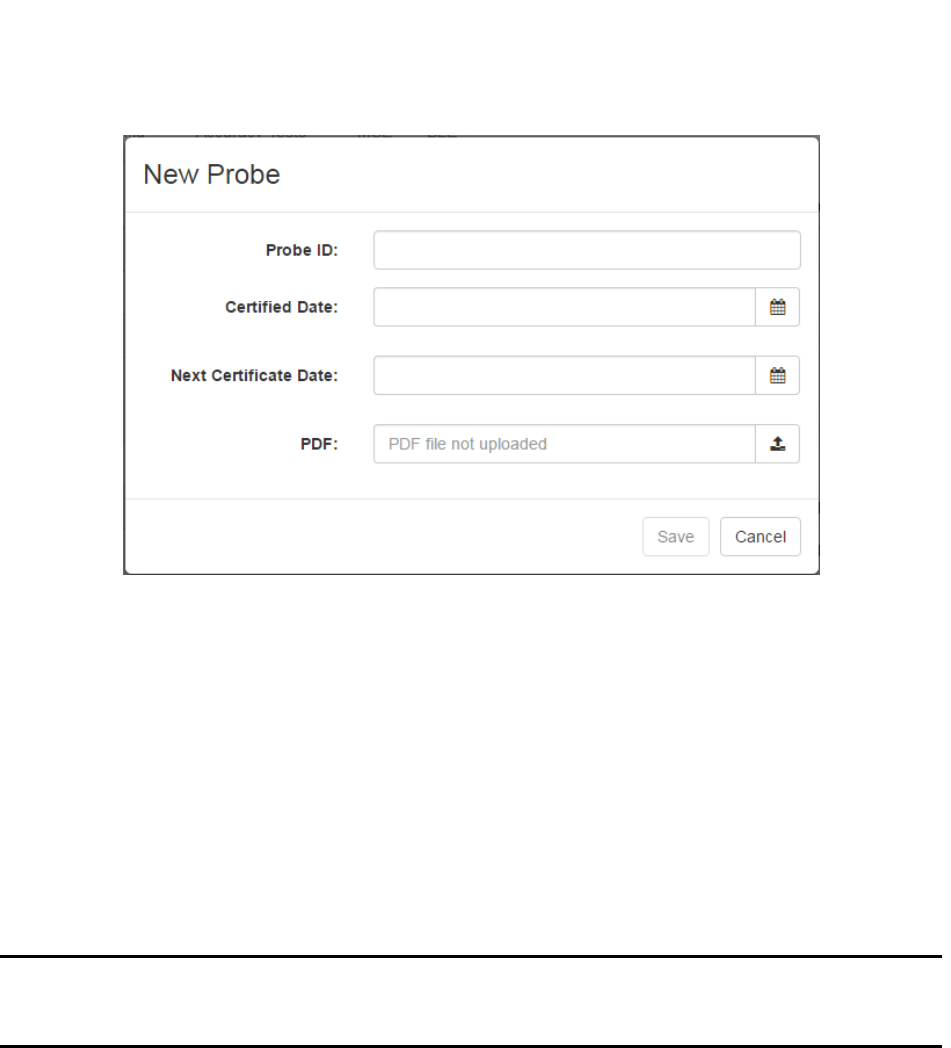
102
System Manager User Guide |
System Manager 2.0
2. In the Probe ID text field, enter the probe’s ID number.
3. In the Certified Date text field, enter the date the probe was certified or click the
calendar icon to select the date.
If you enter the date, the date format is Mmm D, YYYY.
4. In the Next Certificate Date text field, enter the date the probe will need to be re-
certified or click the calendar icon to select the date.
5. In the PDF field, click the upload link to open an explorer window and locate the
PDF certificate for the probe.
NOTE: This upload link will upload one or multiple probe certificates. System
Manager will automatically assign the certificates to the proper probes as
long as they are already in the system.
6. Click Save.
9.2 Viewing a Probe Certificate
From the list of probes, locate the one you want to view the certificate for. Then click
the download icon in the PDF column to view the PDF certificate. The PDF file opens in
a new tab or browser window (depending on your browser settings).
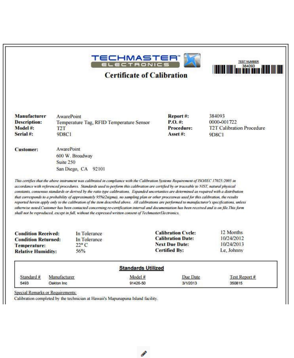
103
System Manager User Guide |
System Manager 2.0
9.3 Editing Probe Details
1. In the Probe Certificates window, locate the probe that you want to update and
click the pencil icon for that probe.
The Update Probe window for that probe displays.
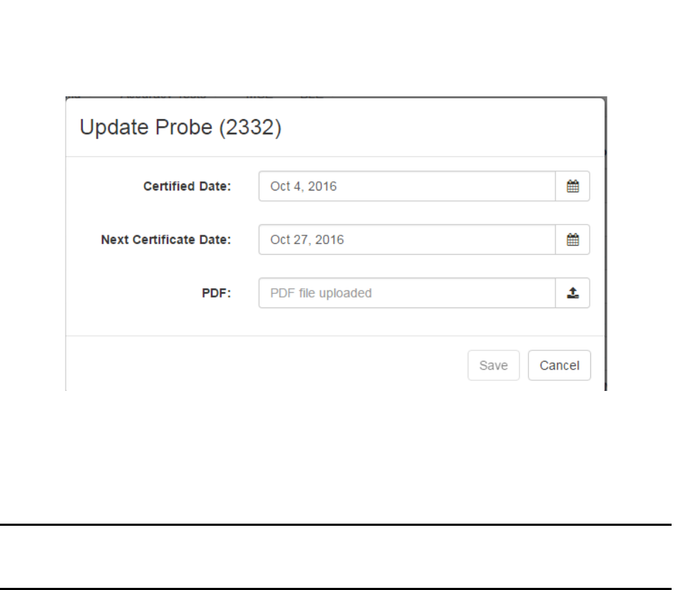
104
System Manager User Guide |
System Manager 2.0
2. Enter new information as necessary in the Certified Date and Next Certificate
Date text fields.
3. In the PDF field, use the upload button to upload a new PDF certificate, if
necessary.
NOTE: This upload link will upload one or multiple probe certificates. System
Manager will automatically assign the certificates to the proper probes as
long as they are already in the system.
4. Click Save to update the probe’s details.
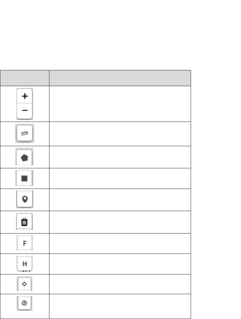
105
System Manager User Guide |
System Manager 2.0
Appendix A. System Manager Tools
SysMapToolbar Icons
ICON DESCRIPTION
Zoom in or out on the map in the viewport area
Mouse scroll wheel also activates this feature
Used to enter the map scale
Creates a new multi-point polygonal region
Creates a new rectangular region
Place a Beacon marker on the map
Delete a selected Beacon from the map
Label a drawn region as a First Order Room
Label a drawn region as a Hallway
Establish a latitude/longitude reference point to
orient maps properly in the location engine
Angle of rotation tool; click to start a line, then
click again to end that line with the second click
pointing the line to true north

Vaccines for Children
Installation and Setup Guide
March 01, 2017

!
"
#$"%
""&"$""'##(")
(**+
,!*-)./"#
)
"01 "
!2"!"
"")
(**+
,!("
"$""$")
(**+
,!*-).#"%(**%33
4/"#)
""%"%"
$"43!2"3!
3"0$""30
4)
(**+
,!4"%%""$""
354""43$"$"64"333)
7#8
/*","
'## 9:,+
!/# ;<.-:
'## 9:,+
!/# ;<.-:
'## 9:,+
!/# ;<.-:
'## 9:,+
!/# ;<.-:
'##(")"01
""2
"
"
/""
)
#$"%
0""
""&"$""'##(")
,!*-)./"#
+
%(**
"01 "
!2"!"
"")
,!("
$""$"
"$""$")
,!*-).#"%(**%33
""%"%"
$"43!2"3!
3"0$""30
,!4"%%""$""
354""43$"$"64"333)
7#8
/*","
!/# ;<.-:
+
!/# ;<.-:
+
!/# ;<.-:
+
!/# ;<.-:
+
"
)
0""
%(**
"01 "
!2"!"
$""$"
"$""$")
,!*-).#"%(**%33
""%"%"
$"43!2"3!
3"0$""30
,!4"%%""$""
354""43$"$"64"333)

1
Vaccines for Children |
Installation and Setup Guide
1 Introduction
Awarepoint’s Temperature tags combined with the Awarepoint software provide an ideal
solution for the monitoring of vaccines for children (VFC) in controlled environments.
The Awarepoint tags provide continual monitoring of environmental assets, alerting
users when temperatures fall out of range.
This document provides information for installing VFC Tag assemblies at facilities and
the setup procedures to enable alerts.

2
Vaccines for Children |
Installation and Setup Guide
2 VFC Hardware
The Awarepoint VFC hardware is comprised of three different pieces:
• Awarepoint Environmental Tag
• VFC Probe
• VFC Display
2.1 Awarepoint Environmental Tag
The Awarepoint Environmental Tags are used to measure and monitor the temperature
in hospital refrigerators, freezers and warmers. Precise temperature monitoring is vital
to ensure patient safety, as well as to remain compliant with medication management
standards and reduce potentially costly product loss.
2.2 VFC Probe
The VFC probe differs slightly from the standard Awarepoint temperature probe in the
following ways:
• The VFC probe cable is 8 feet long.
• The sensor on the VFC probe is a real-time protocol (RTP) sensor that meets
accuracy and range requirements.
Installation of the VFC probe follows the same procedure as described above.
In addition to the differences from other Awarepoint temperature probes, the VFC probe
also has the following requirements:
• Has a temperature range of -55°C to 125°C
• Accuracy requirements:
o -55°C to +50°C: ± 0.25°
o +50°C to +100°C: ± 0.5°
o +100°C to +125°C: ± 0.625°
• Probe must be completely immersed in 30-60 mL of glycol
• The probe end shall be .187" diameter and 3" long
3
Vaccines for Children |
Installation and Setup Guide
• Probe end shall be medical grade stainless steel and must be completely sealed
or potted
• The probe connector shall match the current environmental tag connector and be
backwards compatible
2.3 VFC Display
The VFC display is connected to the temperature tag and attached to the outside of the
temperature-controlled unit for easy viewing. The following figure provides a conceptual
view of the display.
Figure 1 VFC Display Unit
The display has the following requirements:
• Powered by a single 9-volt battery with a minimum 2-year battery life
• 2.7-inch e-ink display with 26x176 resolution
• Displays the tag’s last temperature sample taken
• The device displays the following:
o Current temperature (last sample received)
o Minimum and maximum temperature since last device reset
o Battery health/low battery indicator

4
Vaccines for Children |
Installation and Setup Guide
o “Alarm” indicator when alarm is active
o Displays current minimum and maximum temperature settings from a
button press
• Two buttons on right side of display:
o Reset button
o Mode button
• When powered on, delays any audible alarms for 1 hour. This allows for time
needed to set up and pair the device with a tag, as well as the time needed for
setting the minimum and maximum temperature settings.
2.3.1 Reset Button
The Reset button operates in the following manner:
• When pressed for less than .25 seconds, shuts off the alarm and resets the
max/min temperature.
• When pressed for 3 seconds, temporarily displays the current set points (max
and min allowed temperatures); set points display for 5 seconds.
2.3.2 Mode Button
The Mode button operates in the following manner:
• When the display is off, press for 8 seconds to power on the display.
• When the display is on, press for 6 seconds to power off the display.
• With the display on, when pressed for 1 second, toggles the temperature
readings on the display between degrees F and degrees C.
o Default reading is degrees F
2.3.3 VFC Display Additional Features
The following list identifies additional features and requirements of the VFC display:
• The VFC display device contains a speaker capable of generating audible
alarms.
o The audible alarm level can be set via a config message.

5
Vaccines for Children |
Installation and Setup Guide
o The default audible alarm level is High.
• The VFC display device receives temperature samples from its paired tag via
Bluetooth low energy (BLE)
• The VFC display device also supports WiFi for configuration and firmware
downloading, as well as changing alarm set points, enabling/disabling the audible
alarm, setting the audible alarm level, and pairing with tags.

6
Vaccines for Children |
Installation and Setup Guide
3 VFC Software
The Awarepoint VFC system is set up and run through the following software
applications:
• System Manager – for initial setup
• Infopoint – for creating alerts for non-BLE tags
• awareHealth – for creating alerts for BLE tags
3.1 System Manager
When a tag is brought onsite, System Manager is used to make the Awarepoint solution
aware of the tag, create the configuration necessary for the tag to report and respond as
a VFC tag, and set up the tag’s network connectivity.
3.2 Infopoint
For non-BLE tags, Infopoint is the client interface application to the Awarepoint
Appliance. With Infopoint clients can search for, locate, and track tagged assets on the
Awarepoint network. Clients can also view asset usability statistics, create alerts for
tagged items, and view temperature and humidity data for temperature Tags.
3.3 awareHealth
awareHealth is the client interface application to the Awarepoint Appliance. With
awareHealth clients can search for, locate, and track tagged assets on the Awarepoint
network. Clients can also view asset usability statistics, create alerts for tagged items,
and view temperature and humidity data for temperature Tags.

7
Vaccines for Children |
Installation and Setup Guide
4 VFC Setup Procedures
Setting up the VFC tag and display unit is a multi-step process. In general, the
procedures are:
1. In System Manager, batch create the Environmental Tag and VFC display units.
This step also includes checking the tag and display configuration parameters.
2. In System Manager, pair the tag and display.
3. Power on and provision the tag.
The tag must be powered on first, begin communicating with Infopoint, then the
display can be powered on.
4. Power on and provision the display.
This should be done within 5 minutes of powering on and provisioning the tag.
5. In System Manager, place the tag and display on a map.
6. In Infopoint (or awareHealth), associate the tag with an asset.
7. In Infopoint (or awareHealth), set an alert for when the temperature-controlled
unit goes out of range.
4.1 Batch Creating Devices
The following procedure is done while in System Manager.
1. From the Devices tab drop-down, select Create.
The Batch Create screen displays.
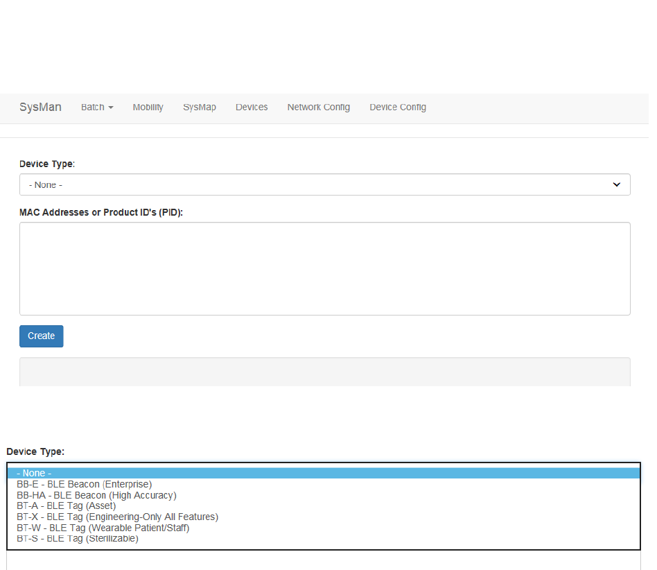
8
Vaccines for Children |
Installation and Setup Guide
2. From the Device Type drop-down, select the type of device you are creating.
3. In the MAC Addresses or Product ID's (PID): field, enter the MAC address or
product ID (PID) of the device or devices.
You can copy and paste this information or enter it by hand. Different MAC
addresses or PIDs must be separated by commas or by carriage returns (one
item per line).
4. Click Create.
4.2 Pairing the Display with the VFC Tag
Pairing of the Display with the VFC tag is done in System Manager before the tag and
display are powered on.
In System Manager, the Device Pairings screen displays a list of devices
(environmental tags) and the displays they are paired to.
From the Devices tab drop-down, select Device Pairings. The Device Pairings
screen displays:
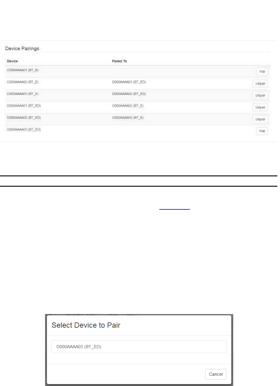
9
Vaccines for Children |
Installation and Setup Guide
4.2.1 Pairing Devices
NOTE: Only environmental tags and displays can be paired.
Only environmental tags and displays that have already been batch created can be
paired. If you have not batch created the devices, do so first before continuing with the
following procedure.
1. From the Device Pairings window, locate the device (environmental tag) you
want to pair with a display.
Only devices that are eligible for pairing display in the first column. Additionally,
the second column for eligible devices will be blank. On the far right, the Pair
button for that device is available.
1. Click the Pair button on the far right.
The Select Device to Pair window displays.
Only devices eligible for pairing appear in this window.
2. Left click on the device you want to pair.
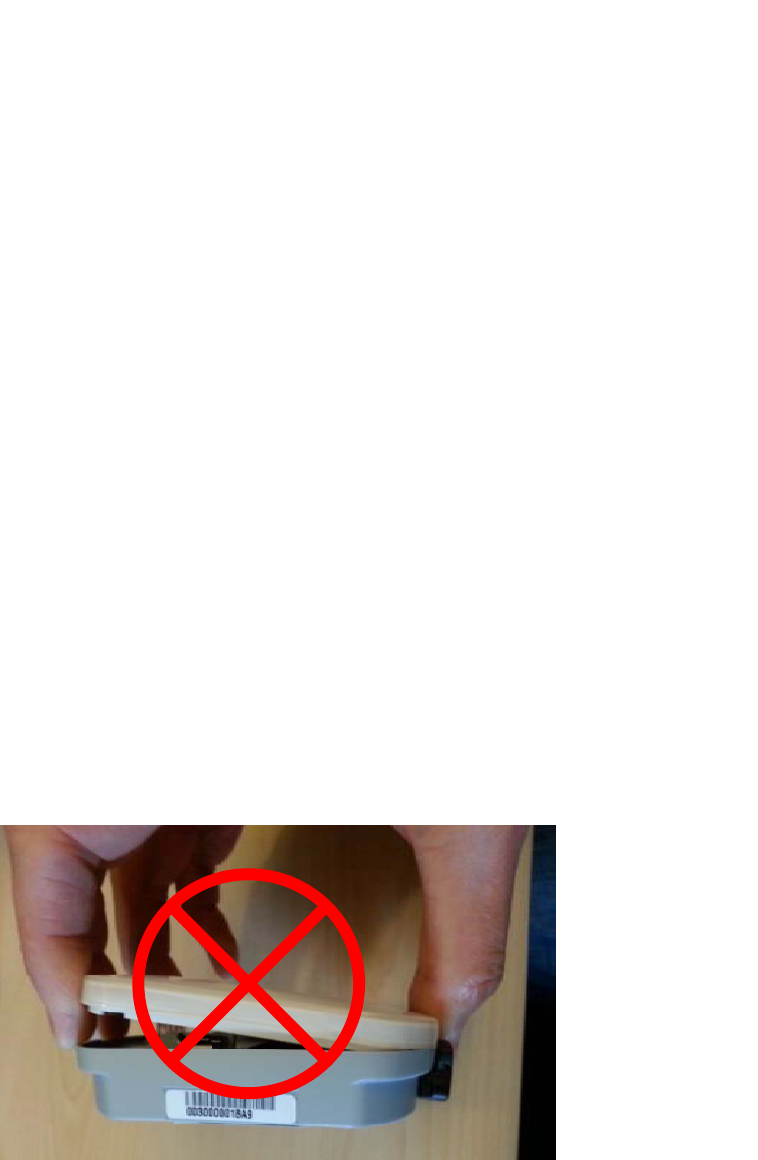
10
Vaccines for Children |
Installation and Setup Guide
The devices are paired and now display as paired in the Device Pairings
window.
4.2.2 Unpairing Devices
1. From the Device Pairings window, locate the devices you want to unpair.
2. On the far right of the row with the devices you want to unpair, click the Unpair
button.
The devices are now unpaired and show as eligible to be paired in the Device
Pairings window.
4.3 Powering On and Provisioning Devices
VFC requires the powering on and provisioning of both hardware devices, the
Environmental Tag and the Display. Perform the following procedures for each
hardware device.
4.3.1 Environmental Tag Battery and Probe Installation
Perform the following procedure to power on the Environmental Tag:
1. Remove the top casing by squeezing the label sides of the tag and pulling up.
2. Pull off the casing, being careful not to pry it up from the non-sensor end.
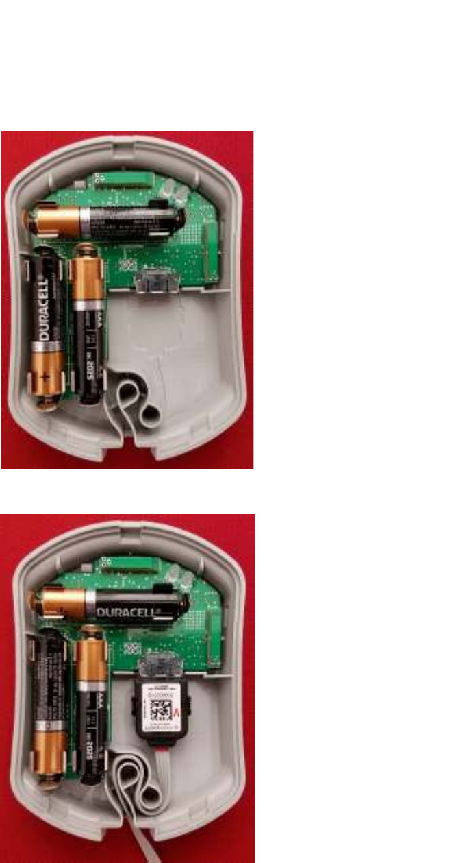
11
Vaccines for Children |
Installation and Setup Guide
3. Insert the three AAA batteries.
4. Insert the probe cable into the slot in the Tag next to the batteries.
When you plug the probe cable in, the LED in the upper right will light up. The
color of the LED will indicate the tag status.
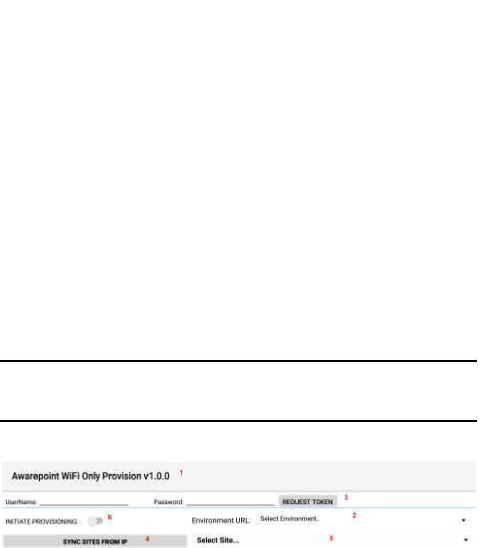
12
Vaccines for Children |
Installation and Setup Guide
o Red – The tag and probe are not communicating. Unplug the probe cable
and reattach. If the red LED still shows, RMA the tag.
o Green – LF message received and probe and tag are communicating.
o Red/Green Consecutively Multiple Times – The probe and cable are not
communicating because of a bad probe. Unplug the probe cable and
reattach. If you still receive the red/green LED, RMA the probe.
o 3 x Green = Good Tag/probe (only when battery or probe replaced)
5. Curl the cord through the loop of the Tag.
6. Close the casing.
4.3.2 Provisioning the Environmental Tag
After a device (tag, display, or beacon) has been batch created, it must be provisioned
so that it can connect to the network and provide location information for tags. Use the
following procedure to provision a device.
NOTE: Before beginning this procedure, an Awarepoint router must be connected
and running close to the tablet running the provisioning application.
Without this router, the SSID for the site will not be available to the app
and the provisioning procedure will fail.
1. Open the Provisioning app on the Awarepoint tablet.
Figure 2 Provisioning Application Main Screen
The following areas should be noted as identified in the figure above:
1) Application version
2) The Environment URL drop-down list
3) The REQUEST TOKEN button
4) The SYNC WITH SITES FROM IP button

13
Vaccines for Children |
Installation and Setup Guide
5) The Select Site drop-down list
6) The INITIATE PROVISIONING slider
2. Enter the username and password for connection to the Awarepoint web
services.
3. From the Environment URL drop-down list, select the environment you are
going to request the token from.
NOTE: There are four main environments to select from. Each environment has
different sites associated with it, so be careful to choose the correct
environment.
4. Press the Request Token button.
If the username and password were correct, a success message displays.
If you do not see a success message, re-enter the username and password and
verify the Environment URL. If you still do not see a request message, contact
the account manager to verify the credentials or to see if there is an outage.
5. Press the SYNC WITH SITES FROM IP button.
Pushing this button pulls a list of all sites associated with the selected
Environment URL.
6. From the Select Site drop-down, select the site to synchronize with.
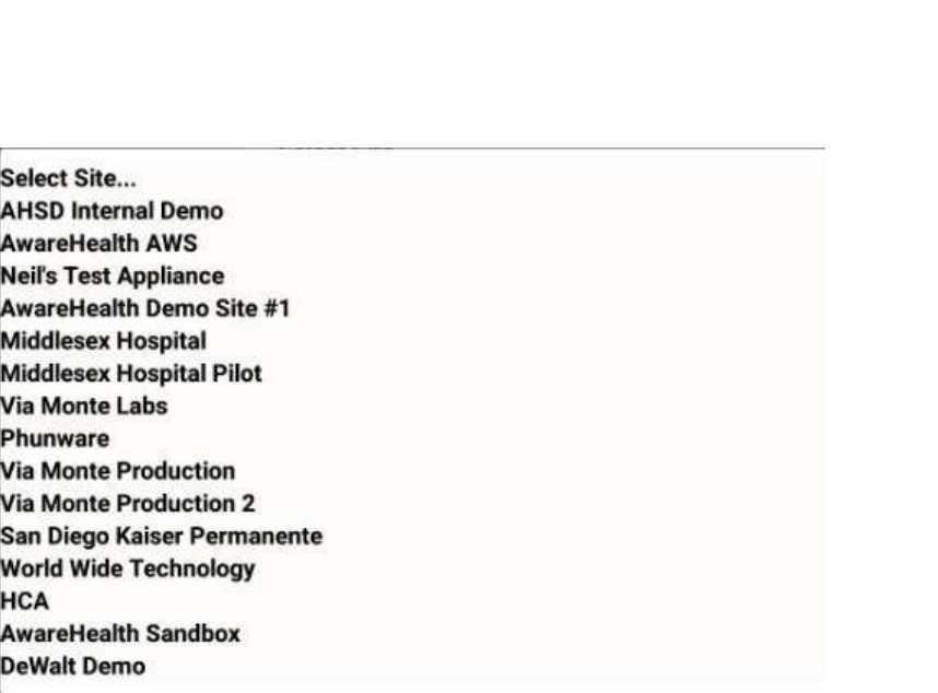
14
Vaccines for Children |
Installation and Setup Guide
Figure 3 Sample Site List
Once you select a site, the SYNC WITH SITES FROM IP button changes to
SYNC WITH SITE.
7. Push the SYNC WITH SITE button.
This option requires an Internet connection.
You must wait until this step completes without any error before proceeding to
the next step. If an error occurs, attempt to SYNC WITH SITE again. If this step
does not complete due to an error, the data will not be available for provisioning
devices.
8. After successful synchronizing with the site is complete, change the Wi-Fi
Network to the SSID named AWP_PROVISION_SERVER.
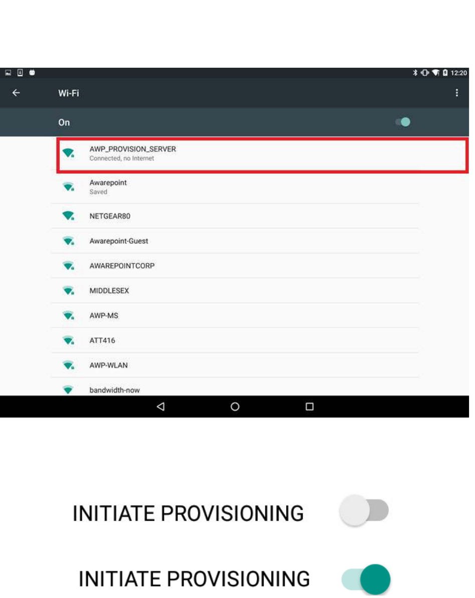
15
Vaccines for Children |
Installation and Setup Guide
This is the SSID in the Awarepoint router. The router must be preconfigured with
the specific security options and the correct SSID name.
9. Slide the INITIATE PROVISIONING slider to the ON position.
Figure 4 INITIATE PROVISIONING in OFF Position
Figure 5 INITIATE PROVISIONING in ON Position
Initiating provisioning does two things:
o Creates a Network Service Discovery that allows the tablet to start
listening for devices in the same network

16
Vaccines for Children |
Installation and Setup Guide
o Creates an SSL Server socket site in order to start communication with
the devices
10. Power cycle the device by pulling the battery out and replacing.
NOTE: If the DEVICES TO PROVISION section is empty (clear list), the tablet will
try to provision every Awarepoint device. If the list is not empty and you have entered
specific device PIDs, the tablet will detect the devices (will appear in DISCOVERED
AWP DEVICES section) but will just provision the devices in the list. Other devices will
be ignored.
11. From the Environment URL drop-down, select the Awarepoint environment you
want to pull network data from.
12. Enter the username and password in the appropriate fields.
These are the credentials to have access to execute the REST Web services to
pull configuration data. This is an Oauth2 security type.
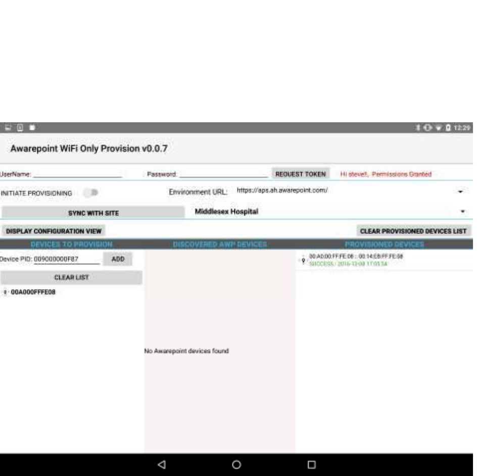
17
Vaccines for Children |
Installation and Setup Guide
13. Press the Request Token button.
If the connection is successful, a Permission Granted message displays.
If you receive a Permission Denied message, check the Environment URL,
username, and password, and retry. If you are still denied, contact the account
manager.
14. Press the SYNC SITES FROM IP button.
This executes a call to pull every site for the Environment URL selected.
When the process of pulling the sites is complete, the SYNC SITES FROM IP
button changes to SYNC WITH SITE.
15. Select a site from the drop-down next to the SYNC WITH SITE button.

18
Vaccines for Children |
Installation and Setup Guide
16. Press the SYNC WITH SITE button.
This begins the data pulling process. Progress bars display at each stage of the
process.
a. Pull Batch Created devices: If the device is not batch created in the system, it
cannot be provisioned.
b. WLanCredentialData: Contains the username and password for an individual
device or a group of devices or a single user and password for the whole site.

19
Vaccines for Children |
Installation and Setup Guide
c. NetworkConfig: Contains the hostname by name or IP.
d. SSIDData: Contains the SSID for an individual device or a group of devices or
a single user and SSID for the whole site.
e. CertificateData: Contains the certification information, private key and ca
Certificate Root. Note that some sites do not require certificate information.
f. WLanSecurity: contains the security information: EAP Method and security
type.
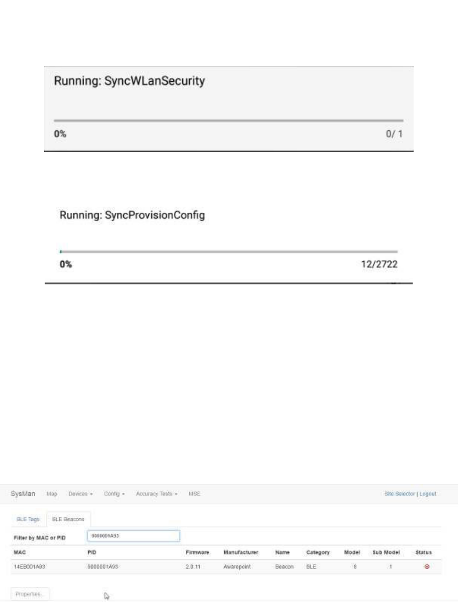
20
Vaccines for Children |
Installation and Setup Guide
g. The last step in the process is to put all the pieces together in order to have
each device have a full configuration.
17. Be sure that the AUTO SCAN and AUTO CONFIG sliders are set to the on
position.
18. After the MAC address of the device shows up in the discovered AWP devices
list, click the MAC address.
19. When the Start WiFi Provisioning button displays, press it.
20. Once the device is provisioned successfully, the PID of the device shows in the
Provisioned Devices list.
After the device has configured, the MAC address of the device(s) will show
along with the PID of the device(s) in the Device Management window.
4.3.3 Setup and Installation of Environmental Tags
Environmental Tags may be deployed by placing the temperature probes in a stabilizing
solution that is mounted inside the refrigerator, freezer, or warmer.
21
Vaccines for Children |
Installation and Setup Guide
Figure 6 Temperature Monitoring Vial for Environmental Tags
The solution prevents non-buffered or uncontrolled swings in temperature that occur
when the doors of temperature-controlled assets are opened. The temperature
monitoring vial contains a 100% glycol solution. Assembly of these vials is completed
on-site.
The following subsections provide the procedures for preparation and deployment of the
hardware.
4.3.3.1 Environmental Tag Installation Required Materials
The following materials are required for each environmental tag being installed:
• Environmental Tag
• VFC Display Unit
• VHB tape
• A minimum of two zip ties per tag to hold excess cord inside and outside of the
temperature-monitored asset
• Two anchors affixed in and out of asset for zip ties
• Three AAA alkaline batteries to power the Tag
• 39 mL (approximately 1.3 fl. oz.) propylene glycol
• Leather punch (to create hole in silicone lid of vial)
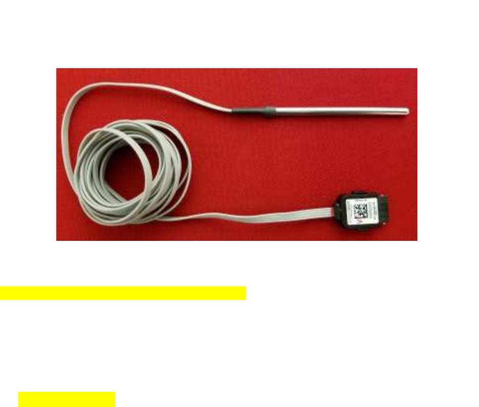
22
Vaccines for Children |
Installation and Setup Guide
The temperature probe comes pre-assembled. No preparation is necessary for
installation.
4.3.3.2 Glycol-based Temperature Vial Setup
Before beginning this procedure, be sure you have the following necessary equipment:
• 40 mL glass vial
• Probe Cable Assembly
• Leather Punch
• Propylene Glycol: 1.3 fluid ounces
1. Fill the glass vial with 1.3 fluid ounces of glycol (approximately 39 mL).
2. Using the leather punch, make a hole in the silicone material in the middle of the
cap assembly.
23
Vaccines for Children |
Installation and Setup Guide
NOTE: The hole should only be large enough to fit the probe snugly so that it
maintains a good seal.
3. Screw the cap assembly onto the glass vial securely.
4. Insert the slim metal tube part of the probe cable assembly into the vial.
4.3.3.3 Physical Installation of Environmental Tags
Environmental Tags are installed on the outside of the asset to be monitored, and the
probe/vial assembly is installed inside the asset. For the most accurate readings, the
probe/vial assembly should be placed near where vaccines are being stored. This
should be in the main body of the temperature-controlled asset away from the walls, the
ceiling, cooling vents or fans, doors and the back of the unit.
24
Vaccines for Children |
Installation and Setup Guide
Figure 7 Example Probe Storage Placement
If a pre-drilled hole through the wall of the asset is available, or a manufacturer’s access
point in the back of the asset, use this existing access point to thread the probe wire into
the asset. If a pre-drilled hole is not available, discuss the possibility of having the
Client’s engineering team drill a hole in the back of the unit for this purpose.
If you are unable to install the probe through the back of the asset or through a hole,
you may thread the wire through the door with written customer documentation to
support the decision to go through the door. If existing temperature monitoring devices
are in place, attempt to install the Awarepoint temperature vial as close to these as
possible. If no temperature-monitoring device exists, install the vial as far back from the
front door of the unit as possible to reduce fluctuations in readings caused by opening
the asset door.
To install the Environmental Tag:
1. Ensure that the TAG MAC is visible and place the Tag on the outside of the
temperature asset using 2 pieces of VHB tape affixed to the back of the unit.
25
Vaccines for Children |
Installation and Setup Guide
Press the Tag firmly against the asset for approximately 30 seconds to ensure
bonding.
2. Feed the probe through any service port on top, back, or side of device.
If a service port or other opening isn’t available, it is recommended that a hole be
drilled so the cord may pass through and the hole sealed after tag installation.
This is not always possible.
3. Using a zip tie and anchor, make a service loop of any excess cord in order to
relieve tension if it is pulled.
For best results, two loops should be placed on the device, one outside and one
inside. A bow shape achieves the best results.
The Tag must be placed on the outside of the asset with the bar code facing
forward or up for easy reading/scanning.
4.3.4 Tag Configuration and Map Placement
VFC Tag and Display devices must have the proper configurations to ensure efficiency.
Additionally, for non-BLE deployments, Tags and Displays must be placed on a facility
map manually. These procedures are performed in System Manager.
4.3.4.1 Tag Configuration Settings
1. In System Manager, select Config > Device Config.
2. From the list of devices on the left, select BT-E to show the configuration settings
for Environmental Tags.
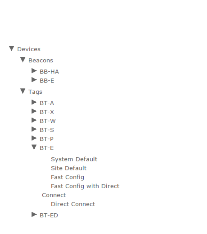
26
Vaccines for Children |
Installation and Setup Guide
3. Select Site Default to display the configuration settings for the site.
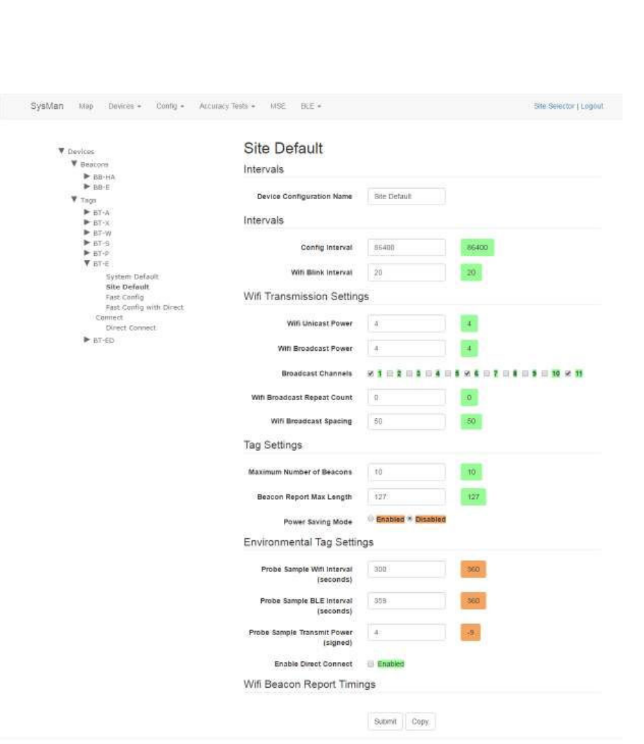
27
Vaccines for Children |
Installation and Setup Guide
A full list of configuration setting descriptions is provided in the System Manager
User Guide.
Most configuration settings can be left at their defaults.
4. Verify the following configuration settings:
o Config Interval – should be set to 86400
Sends a configuration signal to all affected tags every 24 hours
o Probe Sample Wifi Interval (seconds) – should be set to 900
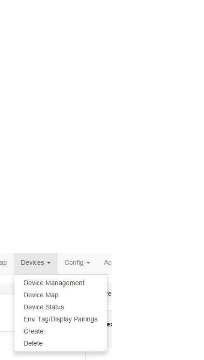
28
Vaccines for Children |
Installation and Setup Guide
For non-BLE tags, sends a probe reading to Infopoint every 15 minutes
o Probe Sample BLE Interval (seconds) – should be set to 150
For BLE tags, sends a probe reading to awareHealth every 2.5
minutes
Additionally, this BLE blink is used by the Display to establish a
connection between the Tag and Display.
5. Click Submit it you made any changes.
Once a Tag has been brought online and configured, any configuration settings
changes will be sent at the Config Interval time (in seconds). If a configuration setting
change needs to be applied sooner than the set interval, power cycle the Tag by
removing the batteries and then replacing them. When the Tag powers back on, it will
take on the current settings.
4.3.4.2 Placing the Device on a Map
In the absence of BLE beacons for a non-MSE deployment, tag and VFC display
placement are done through System Manager by placing the devices on a map during
installation. Perform the following procedure to place the Tag and Display on a map:
1. In System Manager, click the Devices tab and then select Device Map.
A device region manager list displays.
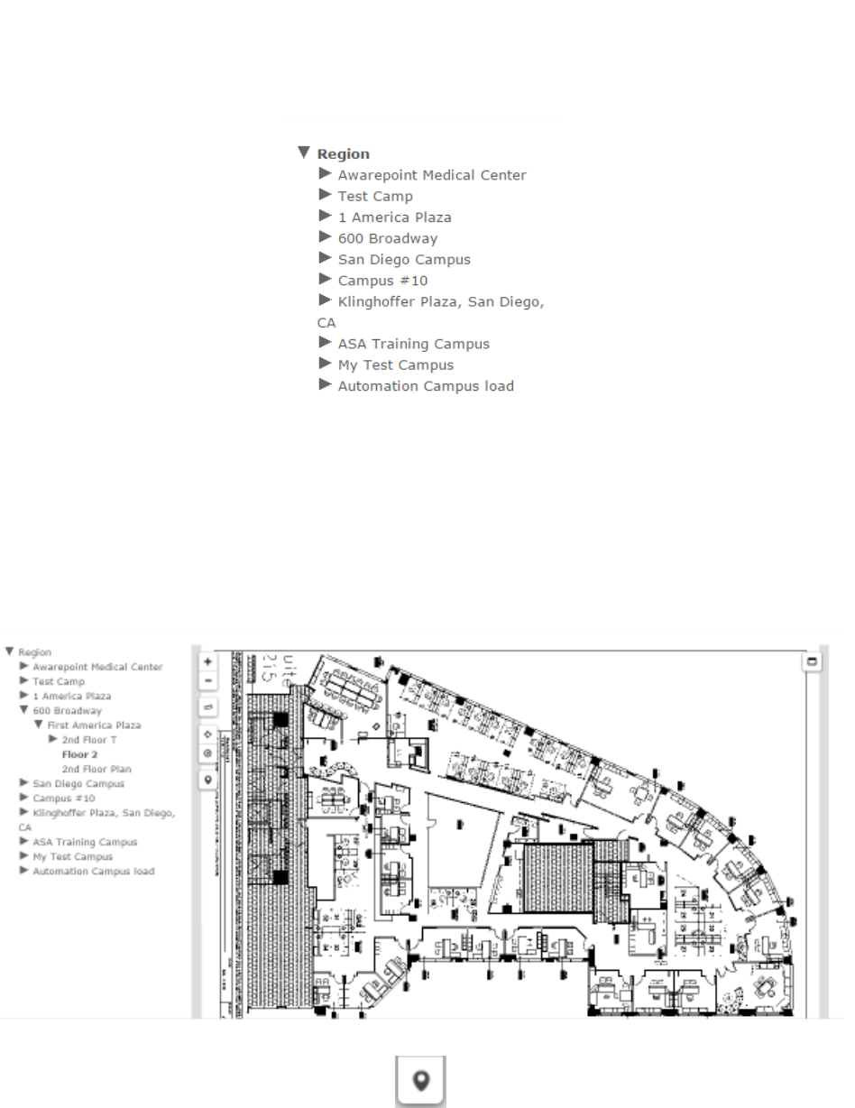
29
Vaccines for Children |
Installation and Setup Guide
2. Expand the list on the left to locate the floor where you will be placing the Tag
and Display.
3. Click the floor.
The floor name will become bold in the list and the map of the floor displays.
4. Click the Devices icon on the left.
The Available Tags dialog displays.
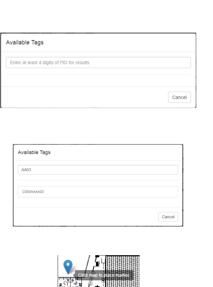
30
Vaccines for Children |
Installation and Setup Guide
5. In the text field, enter at least 4 digits of the device’s PID to start a search for the
device.
A list of devices matching the number you entered displays beneath the text box.
6. Click the PID of the device you want to place.
The window disappears and your cursor appears with a beacon icon.
7. Zoom in on the map in order to place the device as accurately as possible.
8. Click on the map to place the device.
9. If you have placed the device in the wrong place or placed the wrong device,
click the icon to display a list of options.
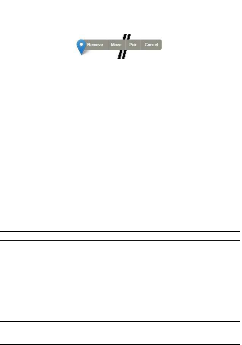
31
Vaccines for Children |
Installation and Setup Guide
To move the device, click the Move link, then click and drag the icon to the new
location.
Click Cancel to cancel the operation and remove the icon.
Click Remove to remove the device icon, then click Ok at the confirmation
dialog.
The Awarepoint tag connects directly to the appliance over WiFi. In an MSE
environment, System Manager configures the tag to use either Broadcast or TCP for
samples and configuration.
4.3.5 Tag Network Connectivity
There are two options for VFC tag network connectivity, direct connect and connection
through the appliance.
4.3.5.1 Tag Direct Connect
When the tag is configured with Direct Connect enabled, it connects directly to the
Awarepoint Appliance to send sample indications rather than sending via WiFi blink.
Perform the following procedure to configure the tag for direct connect:
1. Pair the VFC tag with its display.
NOTE: Only environmental tags and displays can be paired.
Only environmental tags and displays that have already been batch created can
be paired. If you have not batch created the devices, do so first before
continuing with the following procedure.
a. In System Manager, from the Devices tab drop-down, select Env.
Tag/Display Pairings.
b. From the Environmental Tag/Display Pairings window, locate the device
(environmental tag) you want to pair with a display in the Environmental Tag
column.
NOTE: If you are on the Display to Environmental Tag Pairings tab, the first
column would be Display, showing all environmental displays. The
procedure, however, is still similar for pairing.
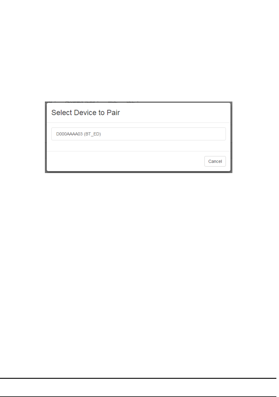
32
Vaccines for Children |
Installation and Setup Guide
Only devices that are eligible for pairing display in the first column.
Additionally, the second column for eligible devices will be blank. On the far
right, the Pair button for that device is available.
c. Click the Pair button on the far right in that device’s row.
The Select Device to Pair window displays.
Only devices eligible for pairing appear in this window.
d. Left-click the device you want to pair.
The devices are paired and now display as paired in the Environmental
Tag/Display Pairings window.
2. Batch create the tag.
a. From the Devices tab drop-down, select Create.
b. From the Device Type drop-down, select the type of device you are creating.
c. In the MAC Addresses or Product ID's (PID): field, enter the MAC address
or product ID (PID) of the device or devices.
d. Click Create.
3. Configure the tag to be a VFC tag.
a. From the devices list on the left, drill down to find the Tag type whose
configuration you want to change or update, then select the configuration
beneath it.
b. Edit each desired field or checkbox to the configuration settings desired.
NOTE: Refer to the System Manager User Guide for detailed information on all
fields and a full description of the configuration process.
c. Click Submit to apply any changes made.

33
Vaccines for Children |
Installation and Setup Guide
4.3.5.2 Tag Connected Through Awarepoint Appliance
Perform the following procedure to configure the tag for use in the Awarepoint solution
with awareHealth:
1. Pair the VFC tag with its display.
See the procedure in Pairing Devices.
2. Batch create the tag.
a. From the Devices tab drop-down, select Create.
b. From the Device Type drop-down, select the type of device you are creating.
c. In the MAC Addresses or Product ID's (PID): field, enter the MAC address
or product ID (PID) of the device or devices.
d. Click Create.
3. Configure the tag to be a VFC tag.
a. From the devices list on the left, drill down to find the Tag type whose
configuration you want to change or update, then select the configuration
beneath it.
b. Edit each desired field or checkbox to the configuration settings desired.
NOTE: Refer to the System Manager User Guide for detailed information on all
fields and a full description of the configuration process.
c. Click Submit to apply any changes made.
Following this procedure, the tag will display in awareHealth and an alert can be set to
notify personnel when the temperature asset goes out of range.
4.3.6 VFC Display Setup
The VFC Display functions as a separate device on the network and requires its own
setup and procedures apart from the Environmental Tag. The setup consists of the
following:
• Batch Creating and Pairing
• Battery Installation and Powering On
• Provisioning

34
Vaccines for Children |
Installation and Setup Guide
• Mounting
These procedures must be done in the order described or the system may not work.
4.3.6.1 Batch Creating and Pairing
Batch creating and pairing of the VFC Display is done following the procedures
previously described.
• Batch creating
• Pairing
4.3.6.2 Battery Installation and Powering On
Perform the following procedure to install the battery and power on the VFC Display:
NOTE: These procedures must be completed within 5 minutes of the
Environmental Tag’s first signal input to Infopoint. If not, the Tag and
Display will wait 30 minutes before attempting to contact each other again
in order to preserve battery life.
1. On the back of the VFC Display, locate the battery cover.
2. Using your thumb, apply some pressure to the ridged area with the area and
slide the cover away from the display.
3. Attach the 9-volt battery to the battery connector.
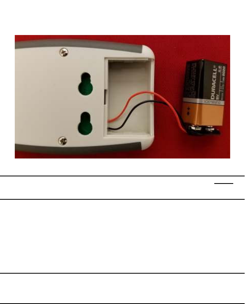
35
Vaccines for Children |
Installation and Setup Guide
4. Place the battery back in the Display and replace the battery cover.
NOTE: Placing the battery back in the Display with the connector wires on top of
the battery instead of underneath makes it easier to close the cover and to
remove the battery later on for changing.
5. Power on the Display by pressing and holding the Mode button for 8 seconds.
6. When the Display powers on, immediately provision the device.
4.3.7 Provisioning the VFC Display
After a device (tag, display, or beacon) has been batch created, it must be provisioned
so that it can connect to the network and provide location information for tags. Use the
following procedure to provision a device.
NOTE: Before beginning this procedure, an Awarepoint router must be connected
and running close to the tablet running the provisioning application.
Without this router, the SSID for the site will not be available to the app
and the provisioning procedure will fail.
1. Open the Provisioning app on the Awarepoint tablet.
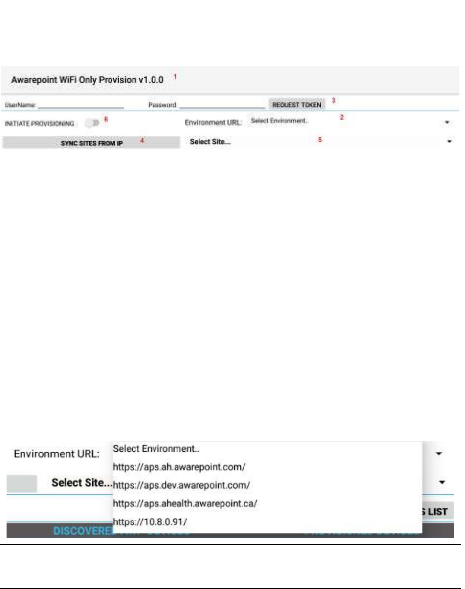
36
Vaccines for Children |
Installation and Setup Guide
Figure 8 Provisioning Application Main Screen
The following areas should be noted as identified in the figure above:
1) Application version
2) The Environment URL drop-down list
3) The REQUEST TOKEN button
4) The SYNC WITH SITES FROM IP button
5) The Select Site drop-down list
6) The INITIATE PROVISIONING slider
2. Enter the username and password for connection to the Awarepoint web
services.
3. From the Environment URL drop-down list, select the environment you are
going to request the token from.
NOTE: There are four main environments to select from. Each environment has
different sites associated with it, so be careful to choose the correct
environment.
4. Press the Request Token button.
If the username and password were correct, a success message displays.
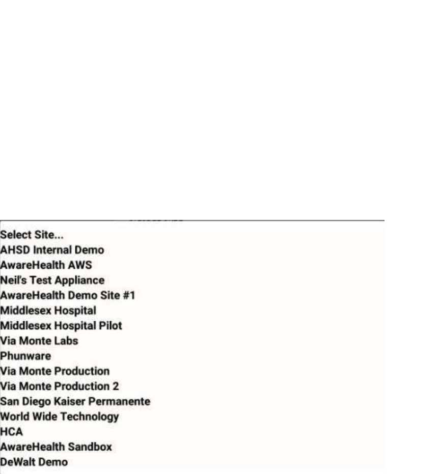
37
Vaccines for Children |
Installation and Setup Guide
If you do not see a success message, re-enter the username and password and
verify the Environment URL. If you still do not see a request message, contact
the account manager to verify the credentials or to see if there is an outage.
5. Press the SYNC WITH SITES FROM IP button.
Pushing this button pulls a list of all sites associated with the selected
Environment URL.
6. From the Select Site drop-down, select the site to synchronize with.
Figure 9 Sample Site List
Once you select a site, the SYNC WITH SITES FROM IP button changes to
SYNC WITH SITE.
7. Push the SYNC WITH SITE button.
This option requires an Internet connection.
You must wait until this step completes without any error before proceeding to
the next step. If an error occurs, attempt to SYNC WITH SITE again. If this step
does not complete due to an error, the data will not be available for provisioning
devices.
8. After successful synchronizing with the site is complete, change the Wi-Fi
Network to the SSID named AWP_PROVISION_SERVER.

38
Vaccines for Children |
Installation and Setup Guide
This is the SSID in the Awarepoint router. The router must be preconfigured with
the specific security options and the correct SSID name.
9. Slide the INITIATE PROVISIONING slider to the ON position.
Figure 10 INITIATE PROVISIONING in OFF Position
Figure 11 INITIATE PROVISIONING in ON Position
Initiating provisioning does two things:
o Creates a Network Service Discovery that allows the tablet to start
listening for devices in the same network

39
Vaccines for Children |
Installation and Setup Guide
o Creates an SSL Server socket site in order to start communication with
the devices
10. Power cycle the device by pulling the battery out and replacing.
NOTE: If the DEVICES TO PROVISION section is empty (clear list), the tablet will
try to provision every Awarepoint device. If the list is not empty and you have entered
specific device PIDs, the tablet will detect the devices (will appear in DISCOVERED
AWP DEVICES section) but will just provision the devices in the list. Other devices will
be ignored.
11. From the Environment URL drop-down, select the Awarepoint environment you
want to pull network data from.
12. Enter the username and password in the appropriate fields.
These are the credentials to have access to execute the REST Web services to
pull configuration data. This is an Oauth2 security type.

40
Vaccines for Children |
Installation and Setup Guide
13. Press the Request Token button.
If the connection is successful, a Permission Granted message displays.
If you receive a Permission Denied message, check the Environment URL,
username, and password, and retry. If you are still denied, contact the account
manager.
14. Press the SYNC SITES FROM IP button.
This executes a call to pull every site for the Environment URL selected.
When the process of pulling the sites is complete, the SYNC SITES FROM IP
button changes to SYNC WITH SITE.
15. Select a site from the drop-down next to the SYNC WITH SITE button.

41
Vaccines for Children |
Installation and Setup Guide
16. Press the SYNC WITH SITE button.
This begins the data pulling process. Progress bars display at each stage of the
process.
a. Pull Batch Created devices: If the device is not batch created in the system, it
cannot be provisioned.
b. WLanCredentialData: Contains the username and password for an individual
device or a group of devices or a single user and password for the whole site.

42
Vaccines for Children |
Installation and Setup Guide
c. NetworkConfig: Contains the hostname by name or IP.
d. SSIDData: Contains the SSID for an individual device or a group of devices or
a single user and SSID for the whole site.
e. CertificateData: Contains the certification information, private key and ca
Certificate Root. Note that some sites do not require certificate information.
f. WLanSecurity: contains the security information: EAP Method and security
type.

43
Vaccines for Children |
Installation and Setup Guide
g. The last step in the process is to put all the pieces together in order to have
each device have a full configuration.
17. Be sure that the AUTO SCAN and AUTO CONFIG sliders are set to the on
position.
18. After the MAC address of the device shows up in the discovered AWP devices
list, click the MAC address.
19. When the Start WiFi Provisioning button displays, press it.
20. Once the device is provisioned successfully, the PID of the device shows in the
Provisioned Devices list.
After the device has configured, the MAC address of the device(s) will show
along with the PID of the device(s) in the Device Management window.
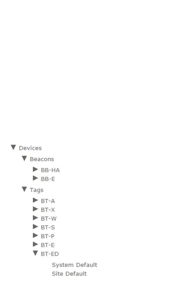
44
Vaccines for Children |
Installation and Setup Guide
4.3.8 VFC Display Configuration and Map Placement
VFC Tag and Display devices must have the proper configurations to ensure efficiency.
Additionally, for non-BLE deployments, Tags and Displays must be placed on a facility
map manually. These procedures are performed in System Manager.
4.3.8.1 VFC Display Configuration Settings
1. In System Manager, select Config > Device Config.
2. From the list of devices on the left, select BT-ED to show the configuration
settings for VFC Display devices.
3. Select Site Default to display the configuration settings for the site.
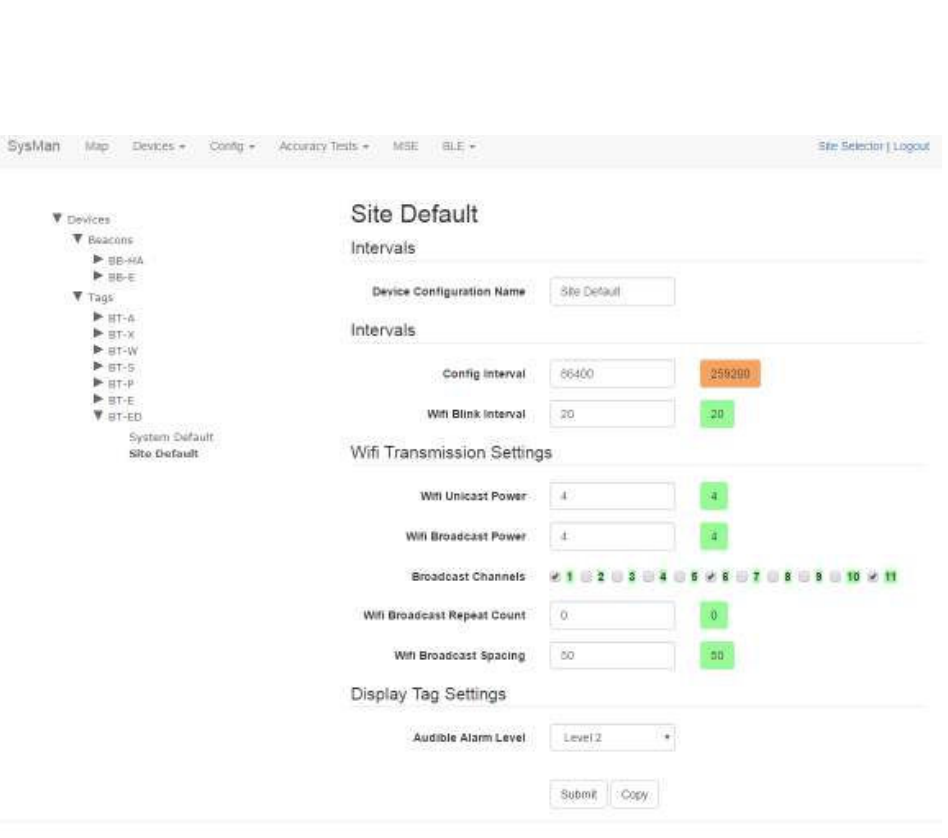
45
Vaccines for Children |
Installation and Setup Guide
A full list of configuration setting descriptions is provided in the System Manager
User Guide.
Most configuration settings can be left at their defaults.
4. Verify the following configuration settings:
o Config Interval – should be set to 259200
Sends a configuration signal to all affected display devices every 3
days
o Audible Alarm Level – volume of audible alarm, from OFF to Level 4
Default is Level 2
5. Click Submit it you made any changes.
Once a Display has been brought online and configured, any configuration settings
changes will be sent at the Config Interval time (in seconds). If a configuration setting
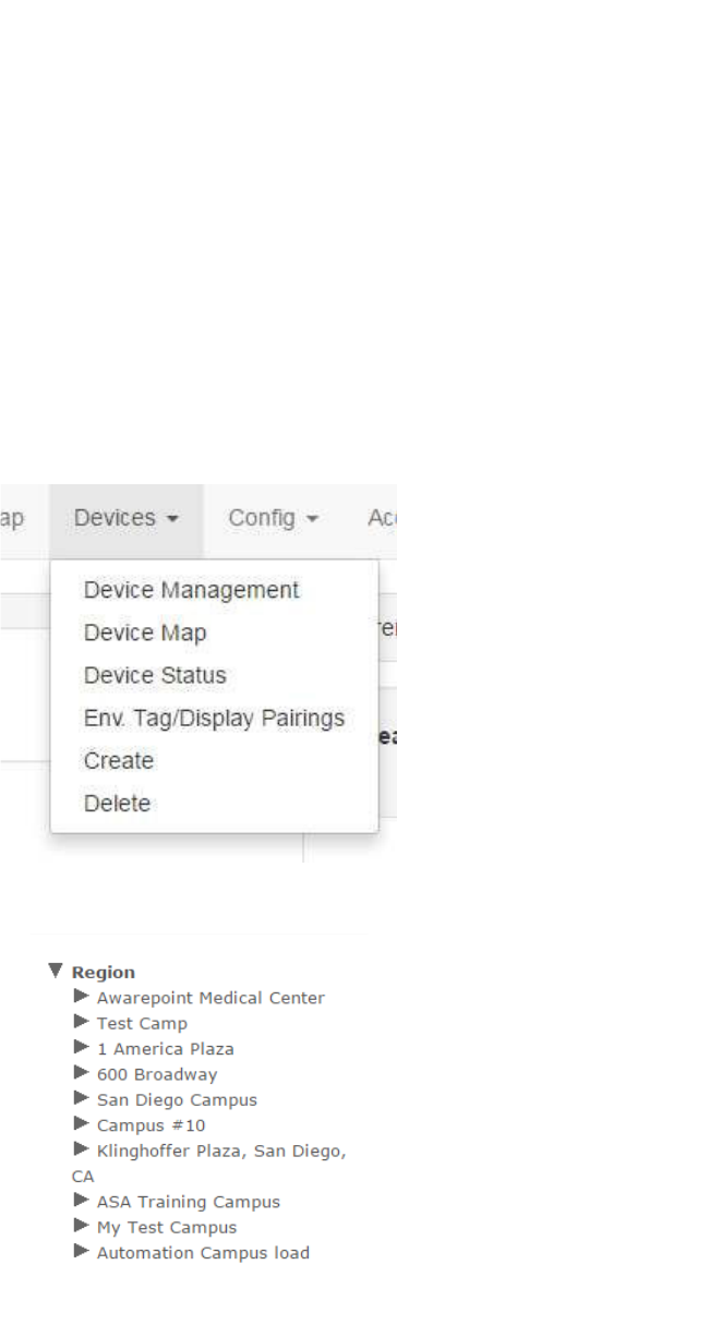
46
Vaccines for Children |
Installation and Setup Guide
change needs to be applied sooner than the set interval, power cycle the Display by
removing the batteries and then replacing them. When the Display powers back on, it
will take on the current settings.
4.3.8.2 Placing the Device on a Map
In the absence of BLE beacons for a non-MSE deployment, tag and VFC display
placement are done through System Manager by placing the devices on a map during
installation. Perform the following procedure to place the Tag and Display on a map:
1. In System Manager, click the Devices tab and then select Device Map.
A device region manager list displays.
2. Expand the list on the left to locate the floor where you will be placing the tag and
Display.
3. Click the floor.
The floor name will become bold in the list and the map of the floor displays.
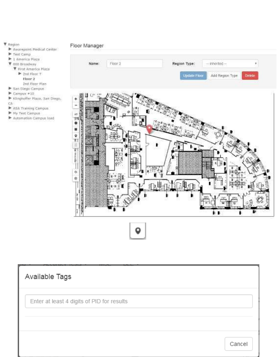
47
Vaccines for Children |
Installation and Setup Guide
4. Click the Devices icon on the left.
The Available Tags dialog displays.
5. In the text field, enter at least 4 digits of the device’s PID to start a search for the
device.
A list of devices matching the number you entered displays beneath the text box.
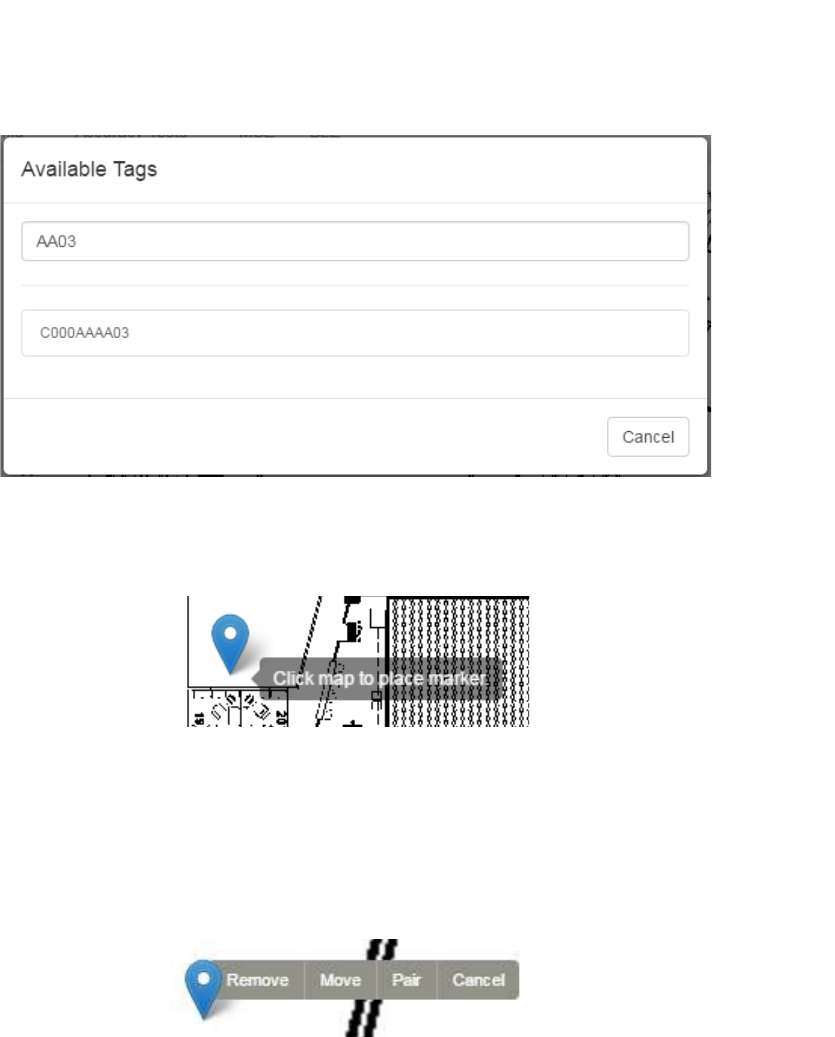
48
Vaccines for Children |
Installation and Setup Guide
6. Click the PID of the device you want to place.
The window disappears and your cursor appears with a beacon icon.
7. Zoom in on the map in order to place the device as accurately as possible.
8. Click on the map to place the device.
9. If you have placed the device in the wrong place or placed the wrong device,
click the icon to display a list of options.
To move the device, click the Move link, then click and drag the icon to the new
location.
Click Cancel to cancel the operation and remove the icon.
Click Remove to remove the device icon, then click Ok at the confirmation
dialog.
4.3.9 Mounting the VFC Display
The VFC Display is mounted on the outside of the temperature asset it is monitoring.
To mount the VFC Display you will need:
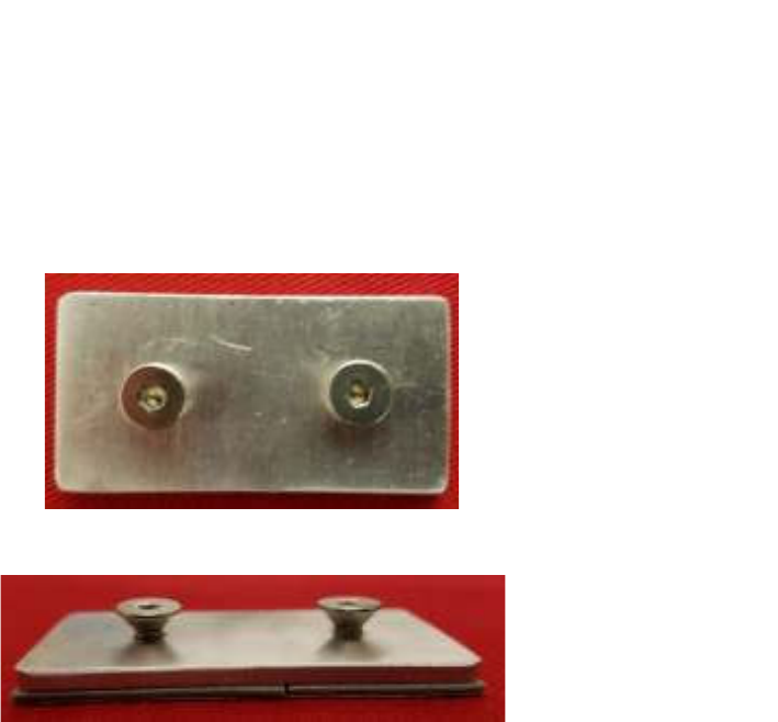
49
Vaccines for Children |
Installation and Setup Guide
• The powered on and provisioned VFC Display
• Mounting bracket
Figure 12 VFC Display Mounting Bracket - Top View
Figure 13 VFC Display Mounting Bracket - Side View
• VHB tape
1. Place a piece of VHB tape on the flat side of the mounting bracket.
2. Locate a clean, dry, flat surface on the outside of the temperature asset and
place the bracket there with the VHB tape, pressing firmly to secure the bracket.
The bracket should be mounted vertically so that the extended parts are one over
the other.
The bracket should also be in a location so that the VFC Display can be easily
read and buttons accessed.
3. Place the VFC Display keyhole openings on the back over the extensions on the
bracket and then slide down to secure the display in place.
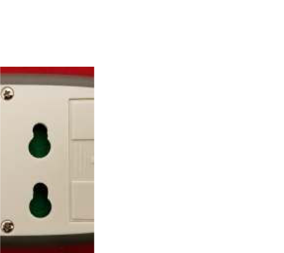
50
Vaccines for Children |
Installation and Setup Guide
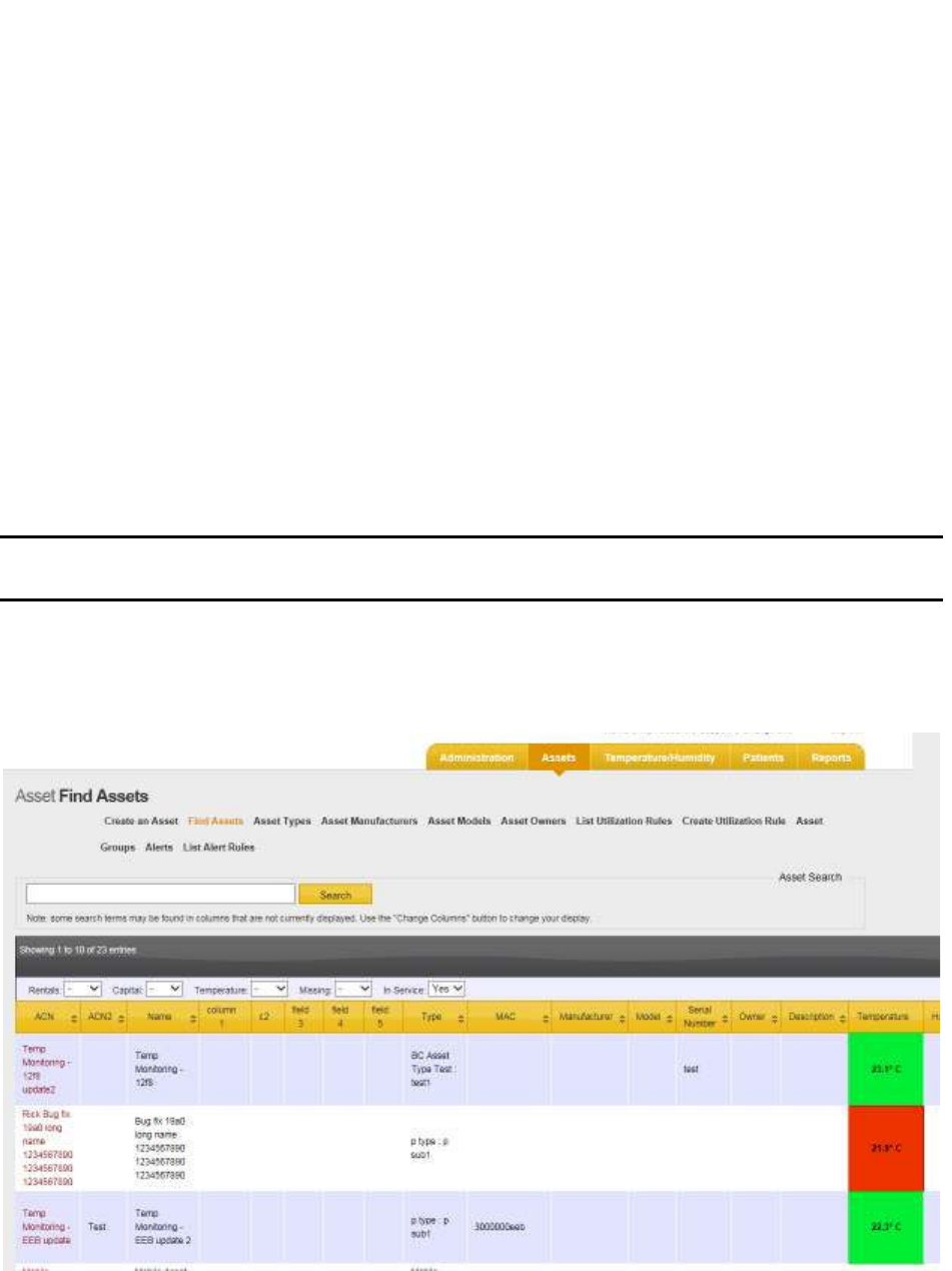
51
Vaccines for Children |
Installation and Setup Guide
5 Associating Tags with Assets
For an alert to be set, the Tag must first be associated with an asset. Associating a Tag
with an asset also allows users to know the location of the asset when an alert
notification is sent. Associating is done in Infopoint or awareHealth.
5.1 Associating a Tag with an Asset in Infopoint
Tags can be associated with an asset in Infopoint by either creating a new asset and
assigning a Tag to it or assigning a tag to an existing asset.
5.1.1 Assigning a Tag to a New Asset
Perform the following procedure to create a new asset and associate a Tag with that
asset.
NOTE: Creating an asset or associating a Tag with an asset may not be available
to all users depending on each user’s permissions.
1. Log in to Infopoint and click the Assets tab.
The Find Assets page displays.
2. Click the Create an Asset link.
The Create New Asset page displays.
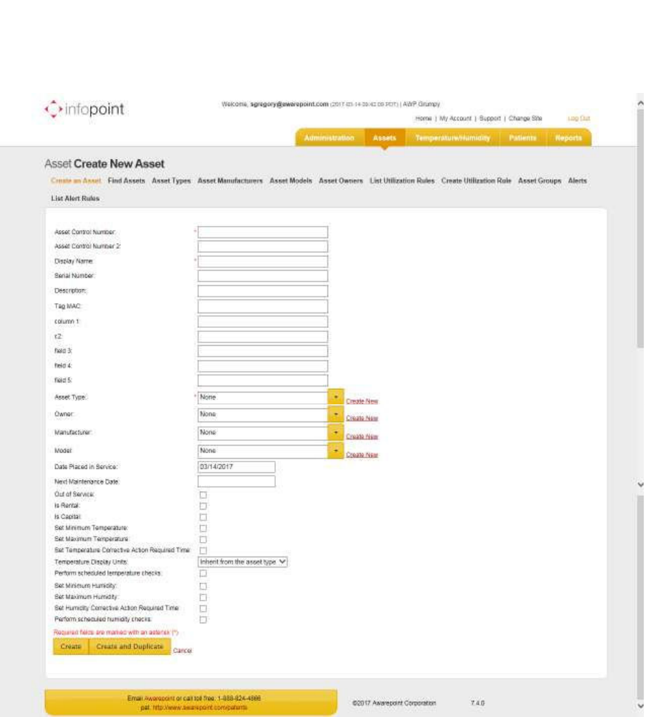
52
Vaccines for Children |
Installation and Setup Guide
3. Fill in the necessary asset information.
Fields marked with an asterisk * are required.
4. In the Tag MAC field, enter the MAC address of the Environmental Tag.
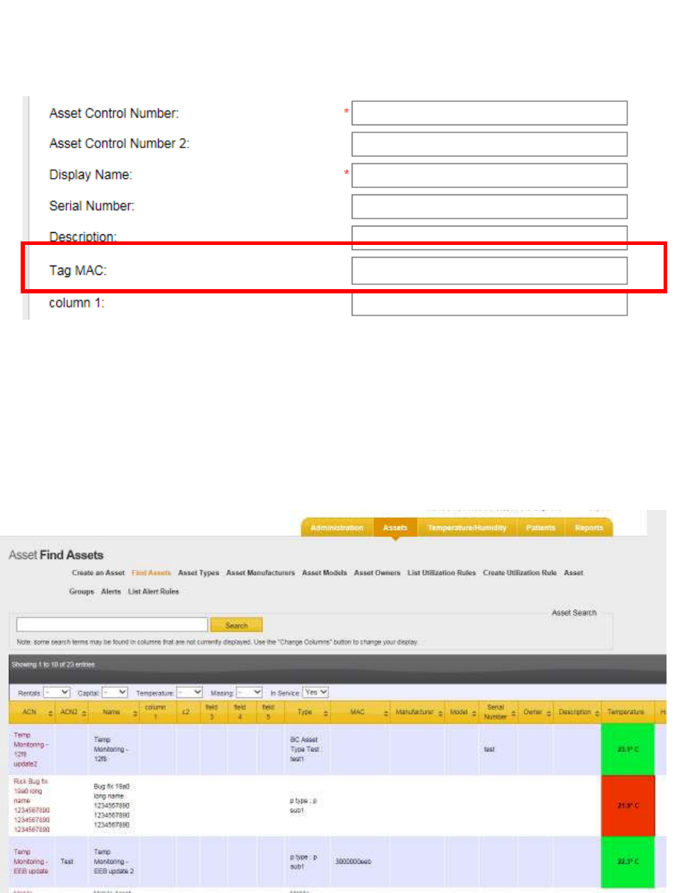
53
Vaccines for Children |
Installation and Setup Guide
5. When done entering all necessary information, click the Create button.
The new asset will appear in the list of assets with associated Tag.
5.1.2 Assigning a Tag to an Existing Asset
1. Log in to Infopoint and click the Assets tab.
The Find Assets page displays.
2. Using either the Search text box or by scrolling through the list of assets, locate
the asset you want to assign a Tag to and click the ACN (link in first column) of
that asset.
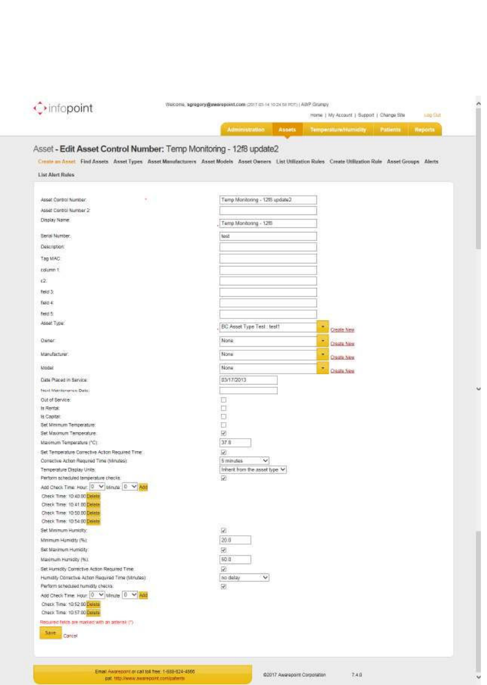
54
Vaccines for Children |
Installation and Setup Guide
The Edit Asset Control Number page displays.
3. In the Tag MAC field, enter the MAC address of the Environmental Tag.
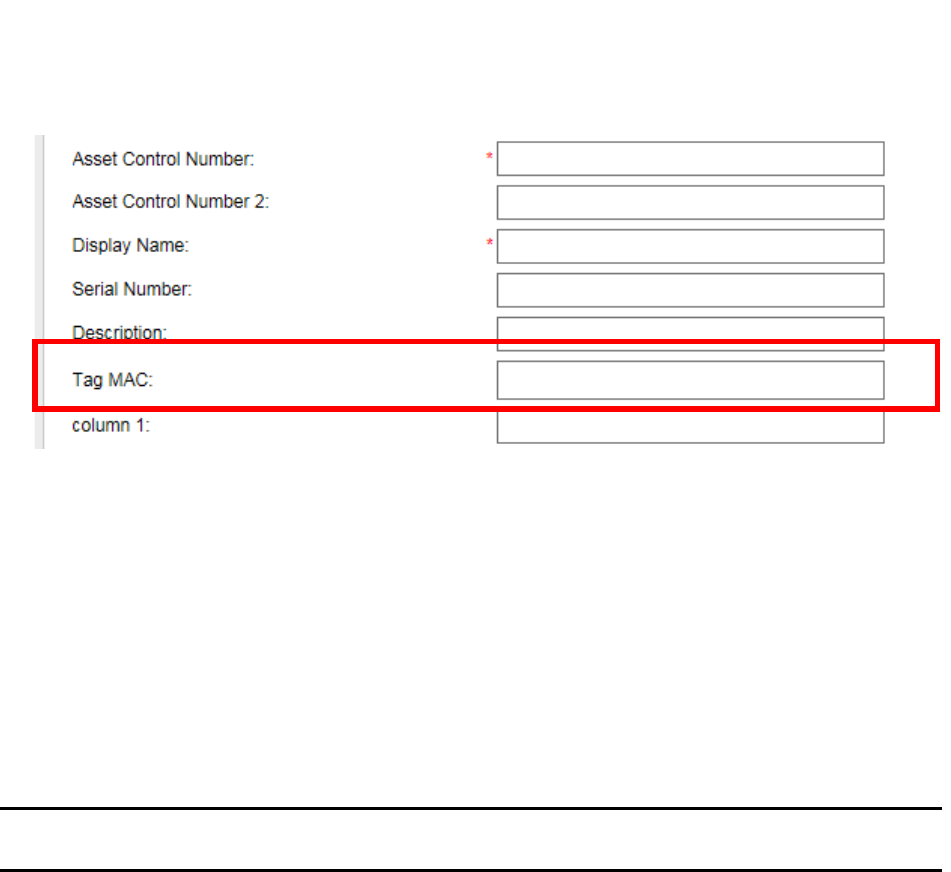
55
Vaccines for Children |
Installation and Setup Guide
4. Click the Save button.
The asset is now associated with the Environmental Tag.
5.2 Associating a Tag with an Asset in awareHealth
Tags can be associated with an asset in awareHealth by either creating a new asset
and assigning a Tag to it or assigning a tag to an existing asset.
5.2.1 Assigning a Tag to a New Asset
Perform the following procedure to create a new asset and associate a Tag with that
asset.
NOTE: Creating an asset or associating a Tag is available only to users with
administrator privileges.
1. Log in to awareHealth and click the Admin tab.
The Asset Manager page displays.
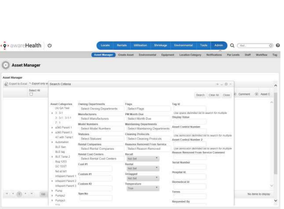
56
Vaccines for Children |
Installation and Setup Guide
2. In the Search Criteria pop-up, click the Close button in the upper right to close
it.
3. Underneath the Asset Manager page title, click the Create Asset button.
The Create Asset window displays.
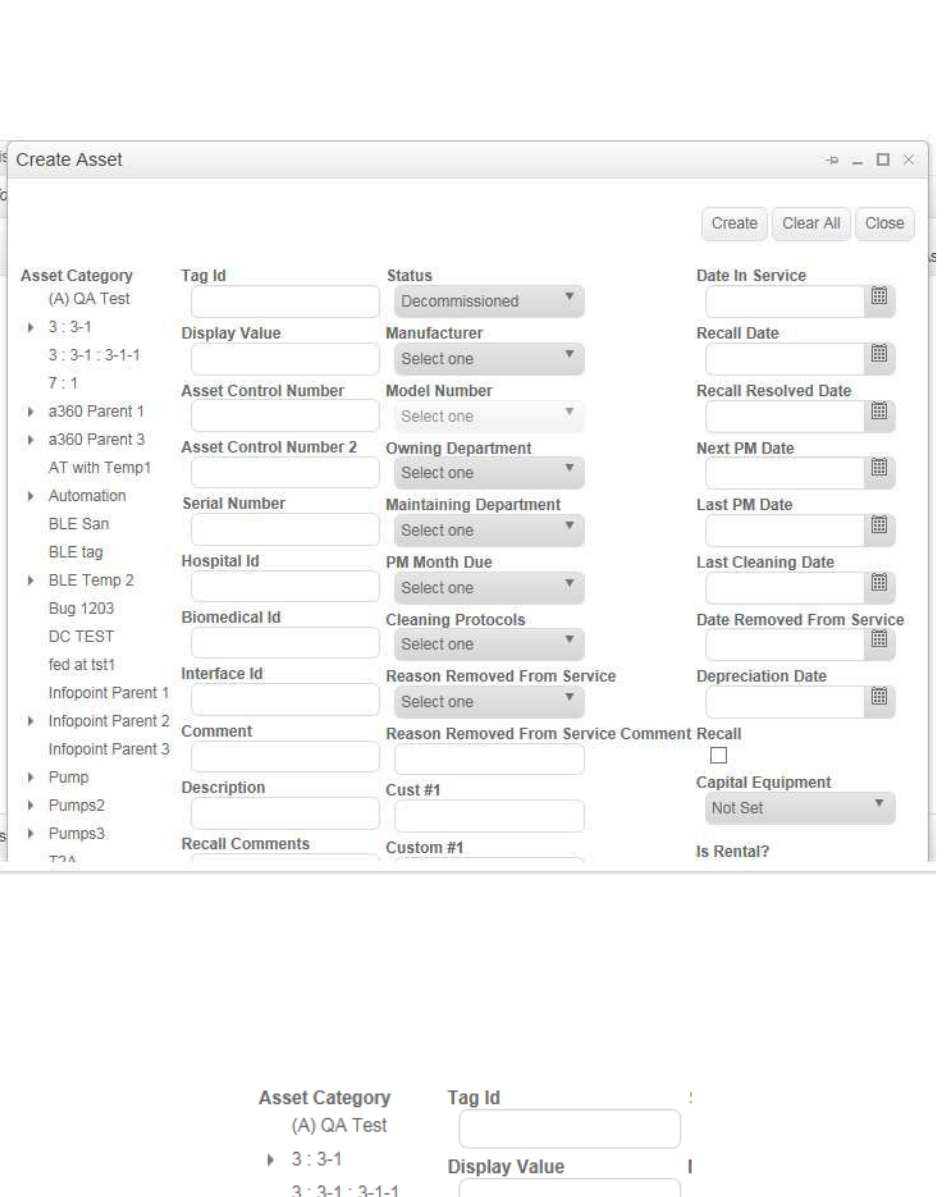
57
Vaccines for Children |
Installation and Setup Guide
4. Fill in all information for the asset as needed, including selecting the Asset
Category.
5. In the Tag Id field, enter the ID number of the Environmental Tag you are
associating with the asset.
6. Scroll to the bottom of this window and select the checkbox for Is Temperature?
to indicate this is a temperature asset.
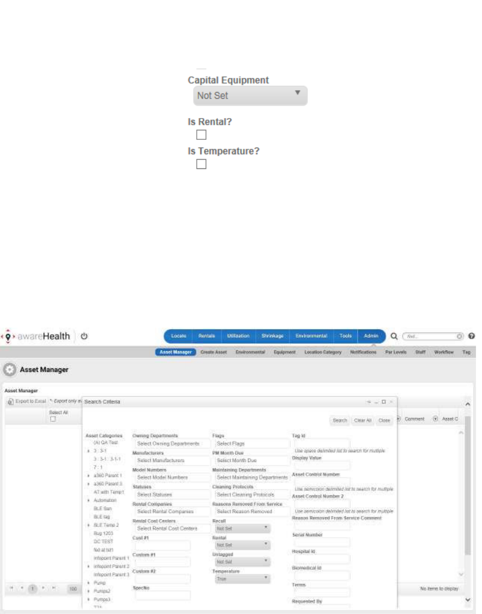
58
Vaccines for Children |
Installation and Setup Guide
7. When done, click the Create button in the top right of the window.
The new asset has been created with the associated Environmental Tag.
5.2.2 Assigning a Tag to an Existing Asset
1. Log in to awareHealth and click the Admin tab.
The Asset Manager page displays.
2. In the Search Criteria pop-up, enter any search criteria that might be necessary
to help locate the asset you want to assign a tag.
3. Click the Search button.
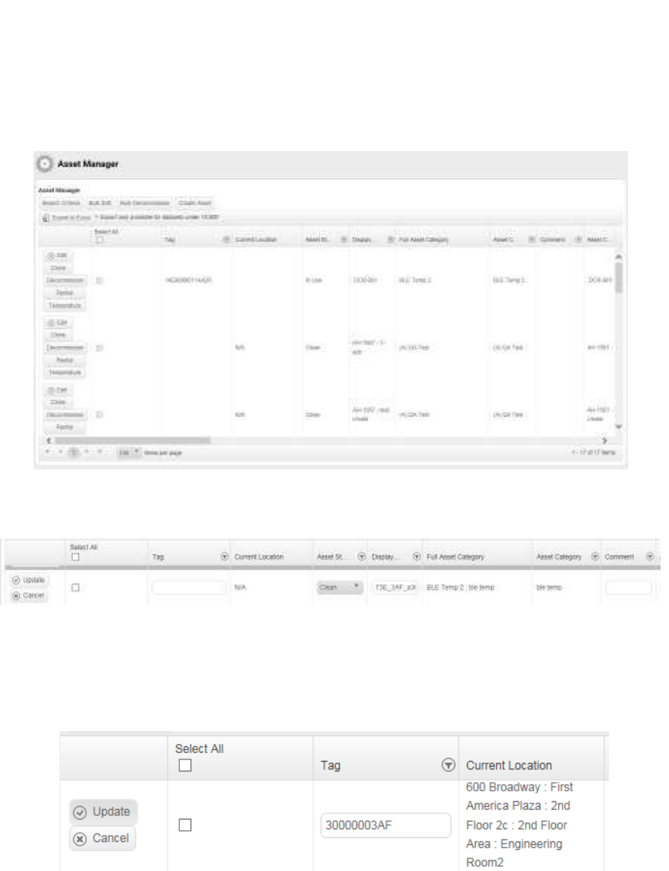
59
Vaccines for Children |
Installation and Setup Guide
A list of assets matching your search criteria displays in the Asset Manager
window.
4. Locate the asset you want to assign the Tag to and click the Edit button on the
far left of the row.
The available buttons change to Update and Cancel and the fields for the asset
become editable.
5. In the Tag column, enter the Tag ID (MAC address) of the Tag you want to
associate with the asset.
6. Click the Update button.
The asset now displays with the associated Tag.
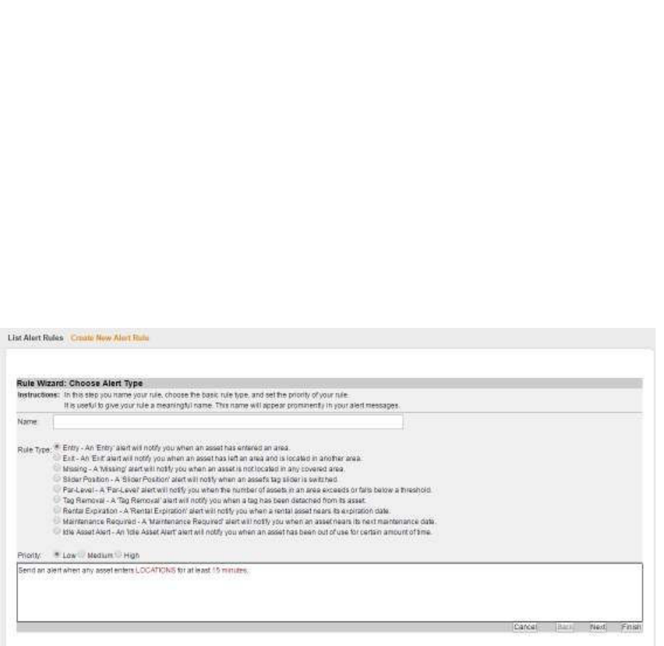
60
Vaccines for Children |
Installation and Setup Guide
6 Setting Alerts
Alerts can be set in Infopoint or awareHealth. When triggered, alerts send notifications
to personnel to check temperature assets to make sure vaccines and other perishables
are kept per regulations.
6.1 Setting an Infopoint Alert
Infopoint allows you to create alert rules that can range from simple to complex. You
can change alert rules only with certain permissions.
From the Asset Rules page, click the Create New Rule link. The Rule Wizard opens.
The first page of the wizard opens as static; however, after choosing a Rule Type, the
wizard moves through steps specific to the selected rule type. For instance, different
information is needed for a Par-Level rule than is needed for a Maintenance Required
rule. Thus, the wizard presents different pages and asks for different information
depending on the rule type.
1. Enter a name in the Name field
Alert names should be indicative of the actual rule. When possible, shorten
spelling. For example, a 1st Floor Lobby Exit Alert could be shortened to “1st Fl
Lobby Exit.”
2. Select a Rule Type check box.
3. Set the rule priority to Low, Medium, or High.
4. Click Next.
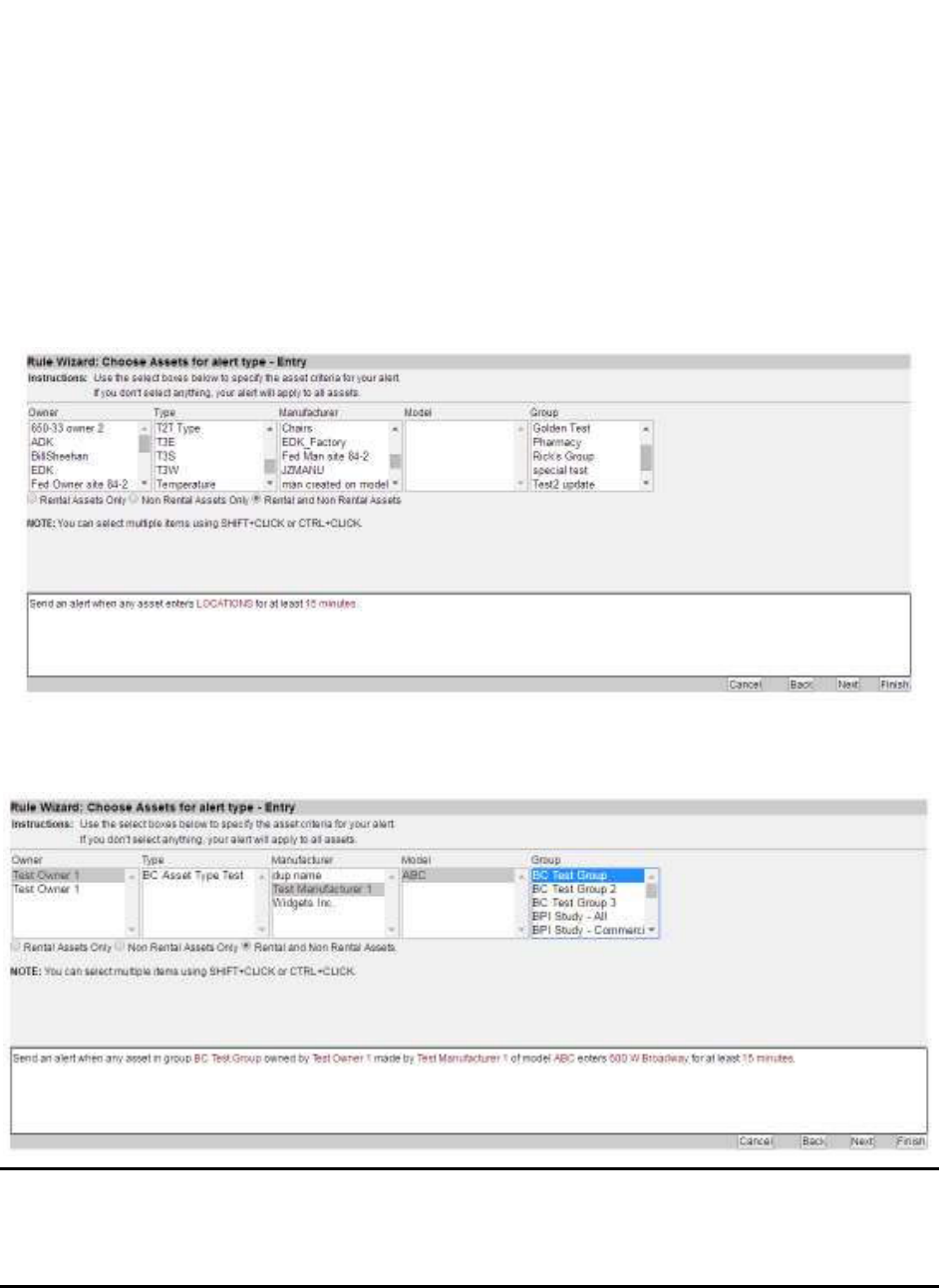
61
Vaccines for Children |
Installation and Setup Guide
You can view the rule being built as you select information in the wizard with the
pane at the bottom of the page that contains additional information. You can
ignore this pane and fill in information later or click on the links and provide the
information at any time during rule creation.
The next step in the rules wizard is a page for selecting target asset attributes or
asset types.
Multiple asset attributes can be selected. You can filter by rental assets and non-
rental assets.
NOTE: Infopoint maintains an asset filtering hierarchy. The selected Owner
determines which Type of asset displays in the following list. The
selected Type determines which Manufacturer displays in the following
list, etc.
5. Click Next.
6. Choose the slider position, if necessary.
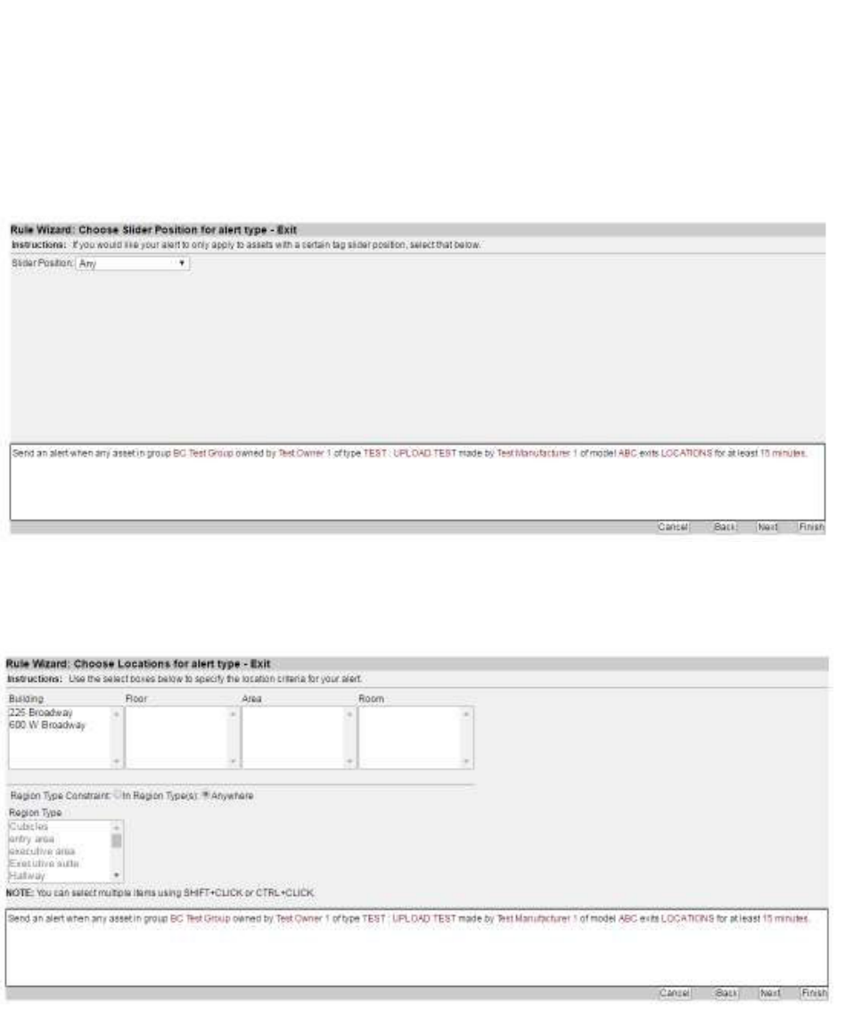
62
Vaccines for Children |
Installation and Setup Guide
Slider position can be set to Any, Red, or Green. Setting a tag to red or green
does not turn the tag on/off. Leaving the position set to the default of Any is
common.
7. Click Next.
The Choose Locations page displays.
8. Choose a location for the alert.
A location is not required for an alert if your rule is for all assets. Locations
should be set if you are specifying a location as an Exit or Entry location.
Location can also be set by clicking the LOCATIONS link in the alert description
pane at the bottom of the page.
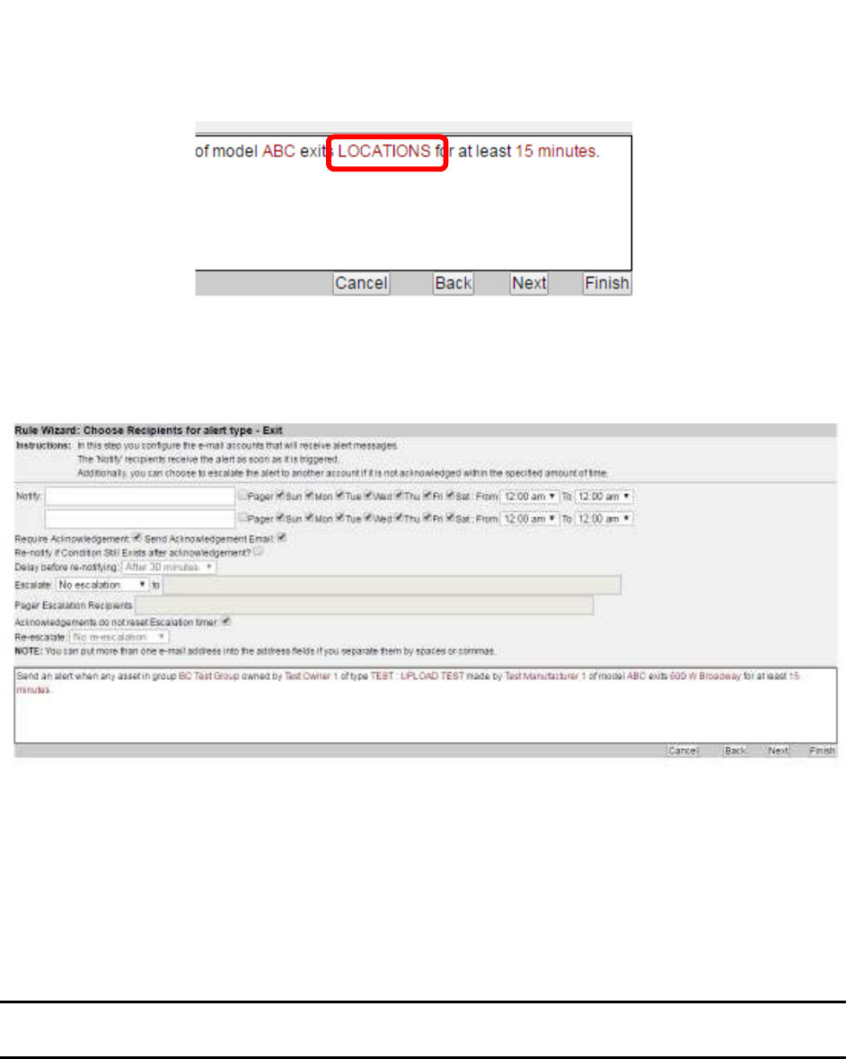
63
Vaccines for Children |
Installation and Setup Guide
9. Click Next.
The Choose Recipients page displays.
10. Enter the email of recipients in the Notify text box, separated by commas.
There are two rows of initial recipients. Using the checkboxes and time drop-
down menus, you can designate initial recipients based on work schedules, as
appropriate.
More rows can be added by clicking Finish, then edit the alert rule and navigate
to this page.
NOTE: All recipients listed on the same line are subject to the same day/time
restrictions.
11. Select the options, including for escalation.
12. Click Next.
The Choose Acknowledgements page displays.
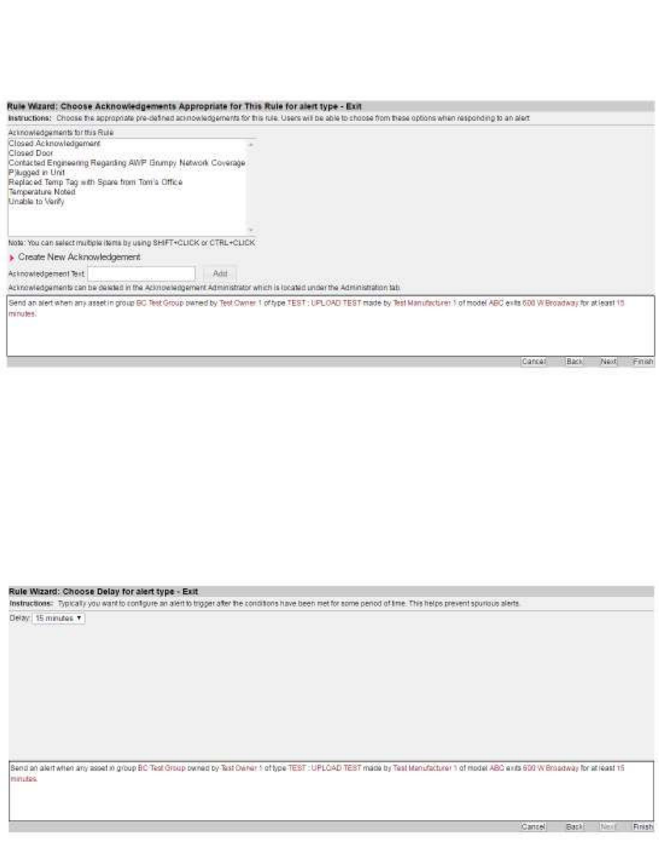
64
Vaccines for Children |
Installation and Setup Guide
13. Select one or more automated acknowledgements a recipient can enter after
responding to the alert.
You can also create a new acknowledgement by clicking the Create New
Acknowledgement link
14. Click Next.
The Choose Delay page displays.
15. Select a delay time before the alert is sent.
Delay times range from 0 minutes to 7 days.
16. Click Finish to create your alert rule.
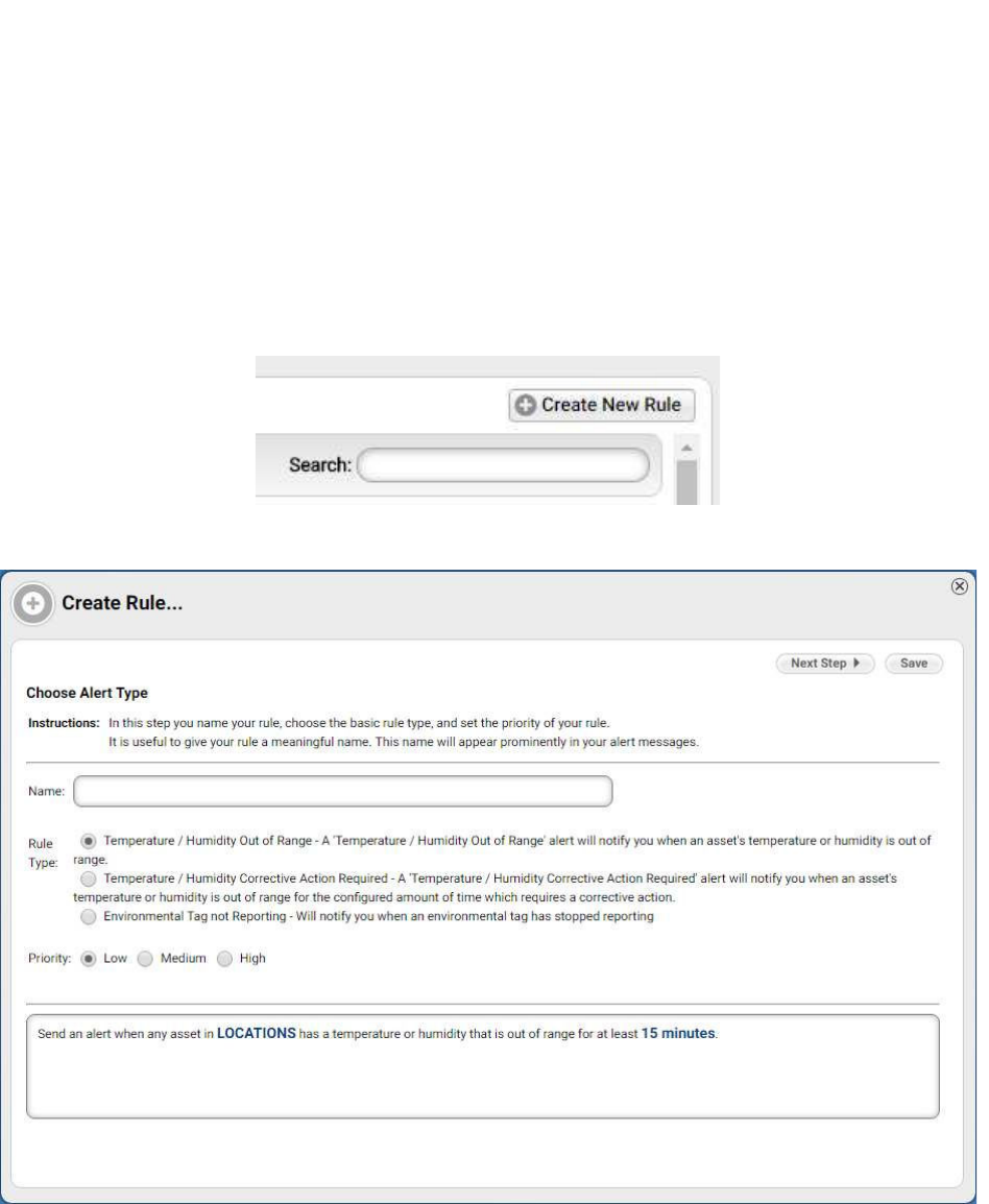
65
Vaccines for Children |
Installation and Setup Guide
6.2 Setting an awareHealth Alert
Alert rules are set from the Environmental tab in awareHealth.
1. From the Environmental tab, click the Alert Rules link.
2. Click the Create New Rule link above the list of current rules.
The Rule Wizard begins and the Choose Alert Type window displays.
3. Enter a name for the rule in the Name text box.
4. Select the radio button for the Rule Type you are creating.
5. Select the radio button for the rule Priority.
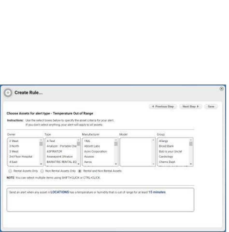
66
Vaccines for Children |
Installation and Setup Guide
In the description text box, LOCATIONS and time (in this example 15 minutes)
are links. You can click these links now to jump to those settings or follow the
steps of the wizard.
6. Click Next Step.
The Choose Assets window displays.
7. From the Owner column, select an owner. You can use SHIFT+CLICK or
CTRL+CLICK to select multiple owners.
After each selection, subsequent columns may change their listings to reflect
only the items that meet the prior column’s filter selection.
8. Select the radio button for the type of assets (Rental Assets Only, Non Rental
Assets Only, or Rental and Non Rental Assets).
9. Click Next Step.
The Choose Locations window displays.
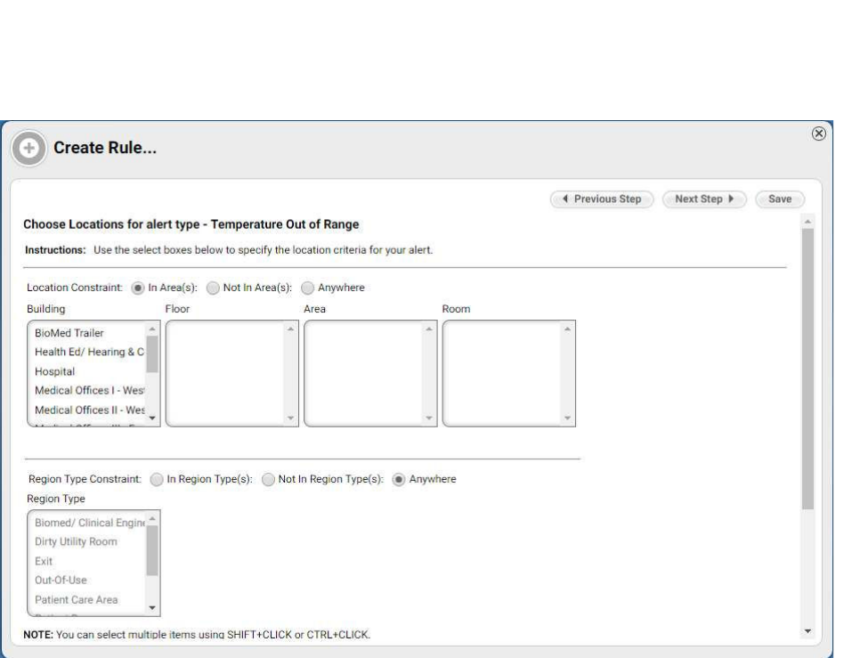
67
Vaccines for Children |
Installation and Setup Guide
10. Select the radio button for the Location Constraint (In Area(s), Not In Area(s),
Anywhere).
11. From the Building column, select a building.
The Floor, Area, and Room columns will populate based on the previous
column’s selection.
12. Select a floor, area, and room.
13. Select the radio button for the Region Type Constraint (In Region Type(s), Not
In Region Type(s), Anywhere).
14. If you selected In Region Type(s) or Not In Region Type(s) in the previous
step, select a Region Type from the types now available in the list box.
If you selected Anywhere in the previous step, the Region Type list box remains
grayed out.
15. Click Next Step.
The Choose Recipients window displays.
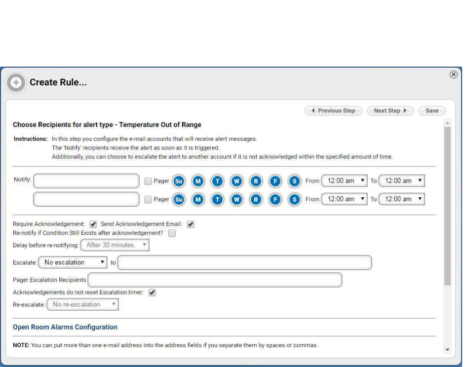
68
Vaccines for Children |
Installation and Setup Guide
16. In the first Notify field, enter the email address of the person to be notified.
Separate emails by a comma if entering more than one email address. You can
enter up to 8 per field.
17. Select the day(s) and time for the recipient(s).
18. In the second Notify field, enter the email address of the person to be notified.
The use of the second Notify field allows you to select different recipients for
alerts. For example, personnel in the first field might work a day shift, while
personnel in the second field work the night shift.
19. Select the checkboxes, as desired, for acknowledgements.
20. If you selected to re-notify, select the time delay for the re-notification.
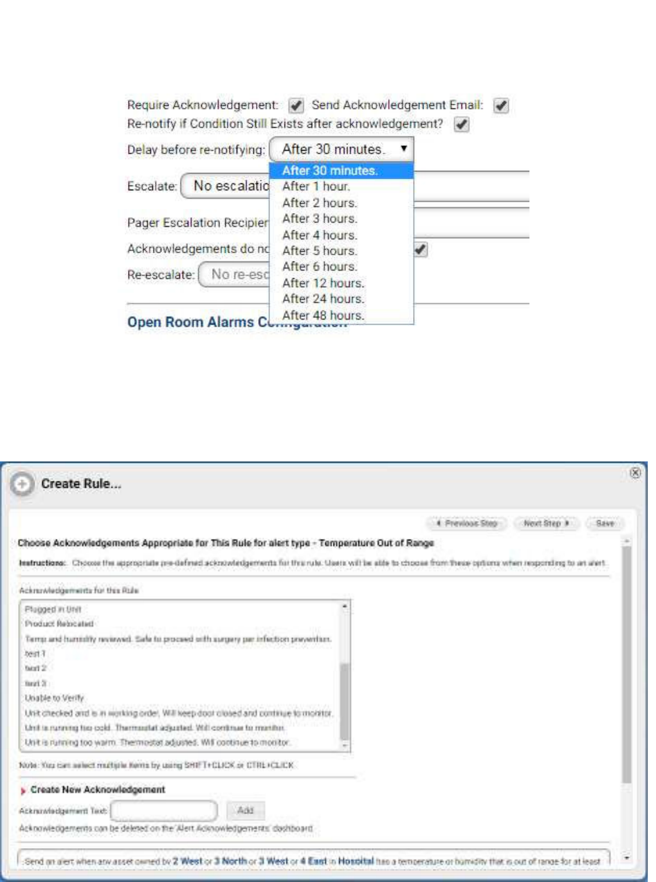
69
Vaccines for Children |
Installation and Setup Guide
21. Select the desired options for escalation.
22. Click Next Step.
The Choose Acknowledgement Appropriate for This Rule window opens.
23. Select the acknowledgement(s) for the rule.
You can use SHIFT+CLICK or CTRL+CLICK to select multiple
acknowledgements.

68
Vaccines for Children |
Installation and Setup Guide
16. In the first Notify field, enter the email address of the person to be notified.
Separate emails by a comma if entering more than one email address. You can
enter up to 8 per field.
17. Select the day(s) and time for the recipient(s).
18. In the second Notify field, enter the email address of the person to be notified.
The use of the second Notify field allows you to select different recipients for
alerts. For example, personnel in the first field might work a day shift, while
personnel in the second field work the night shift.
19. Select the checkboxes, as desired, for acknowledgements.
20. If you selected to re-notify, select the time delay for the re-notification.
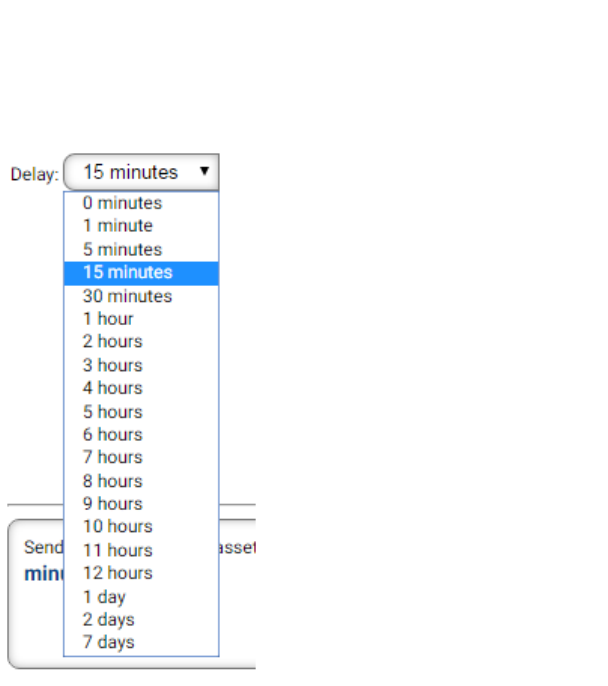
71
Vaccines for Children |
Installation and Setup Guide
26. In the alert text field, read your rule settings to verify they are correct.
Use the Back button to go back to previous windows if you need to make
changes to your rules.
27. Click Save to create the rule alert listing.
Alternatively, clicking the X in the upper right will cancel the creation of the rule
alert listing and return you to the alerts listing.