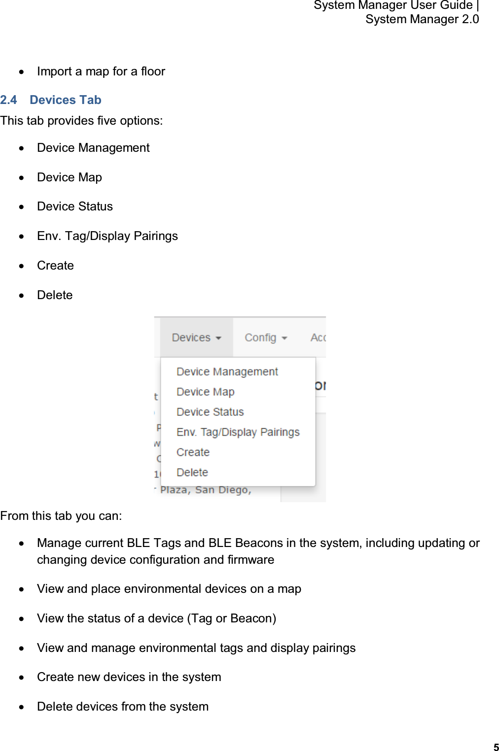
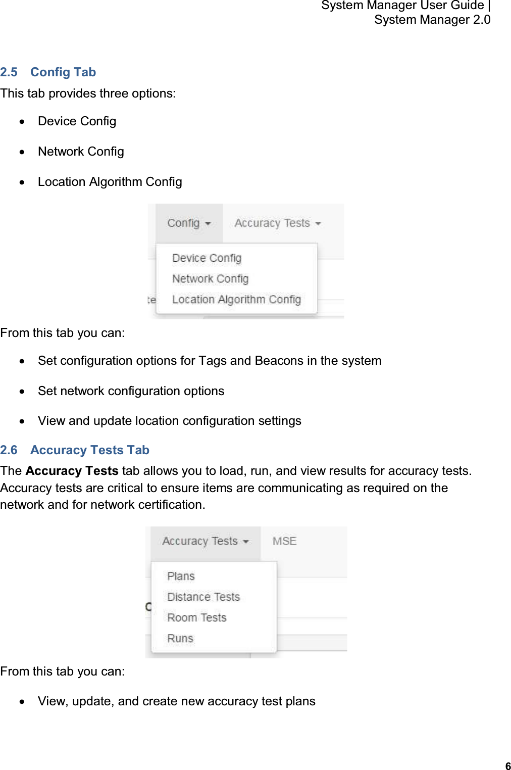
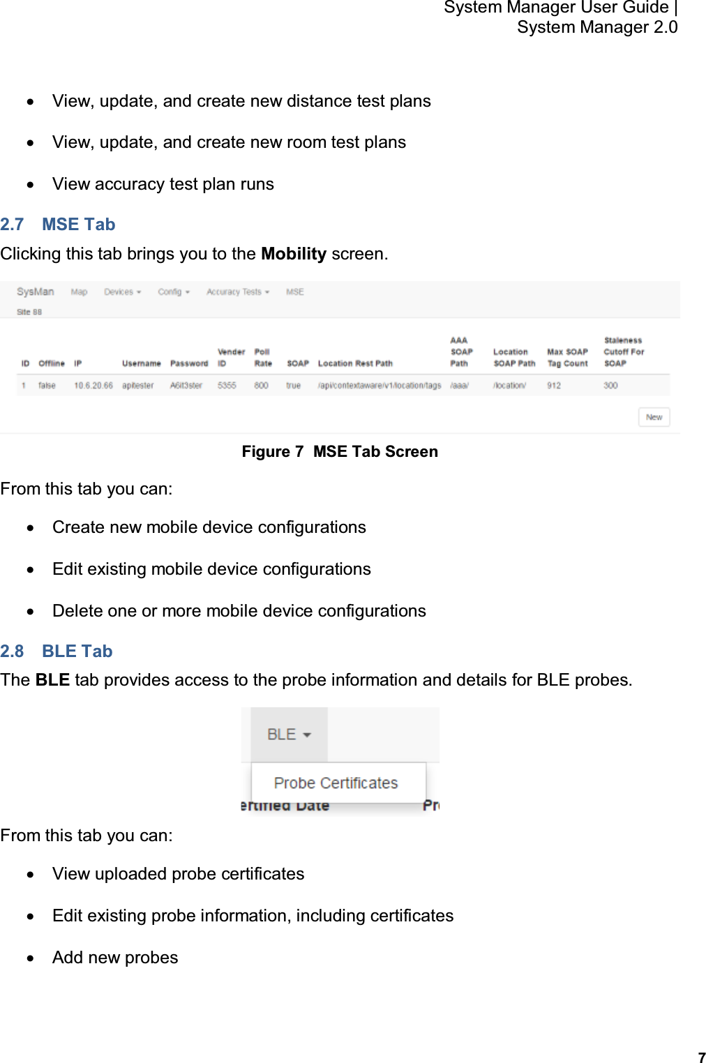
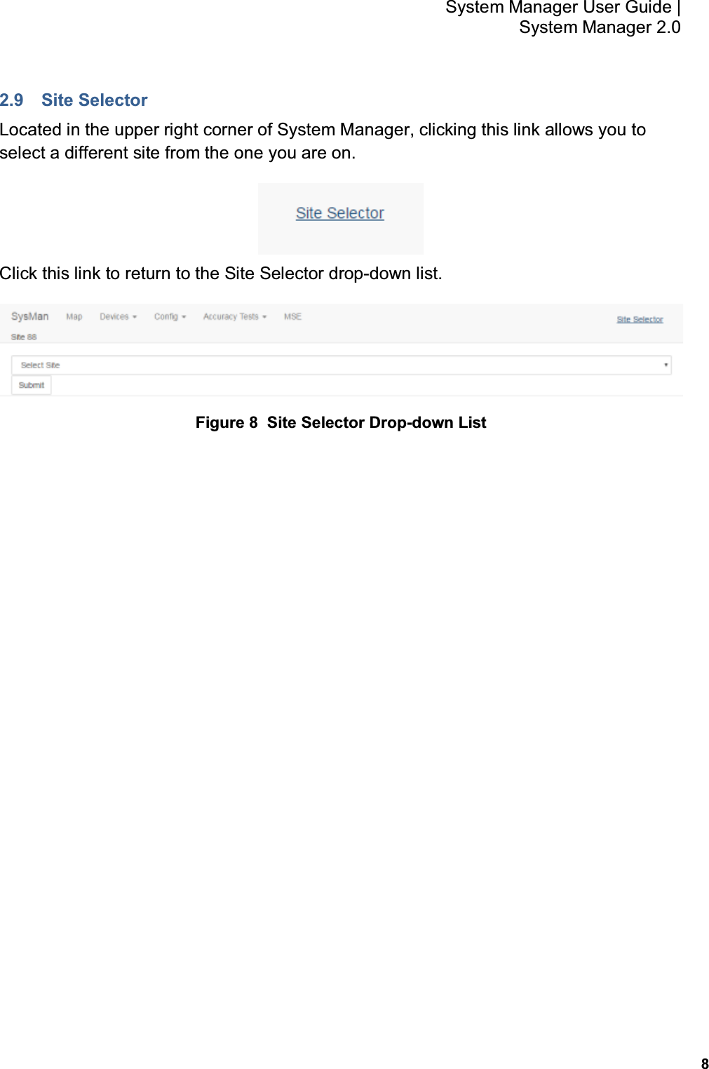
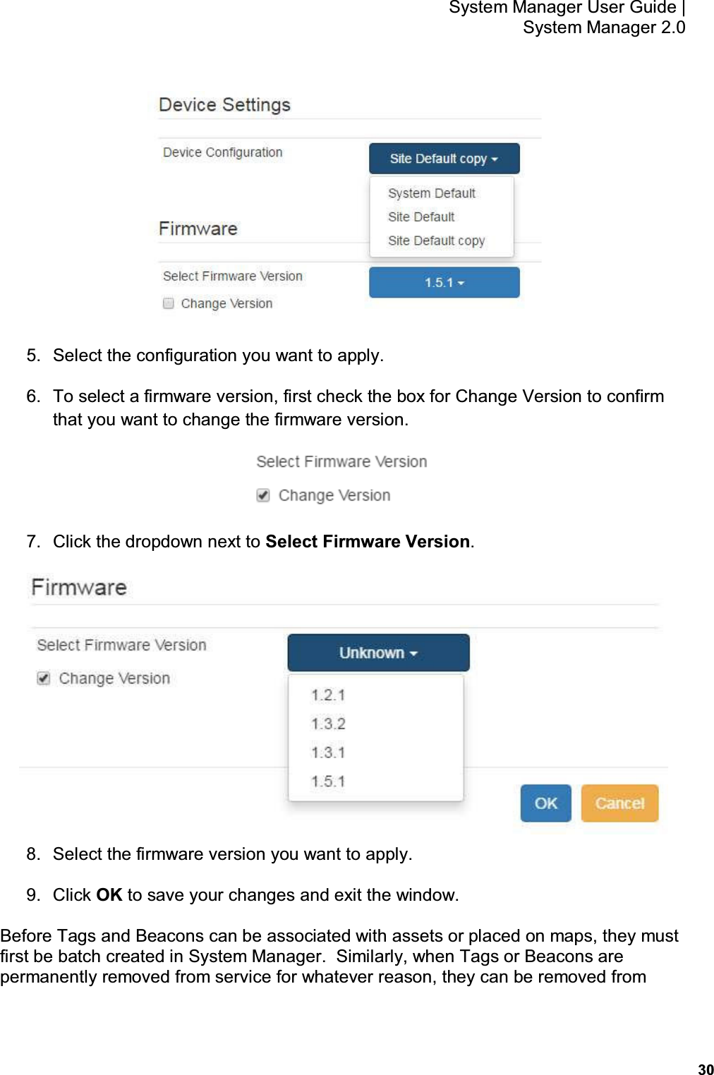
AwarePoint BLET BLET, BLETW User Manual BLEX Manual
AwarePoint Corporation BLET, BLETW BLEX Manual
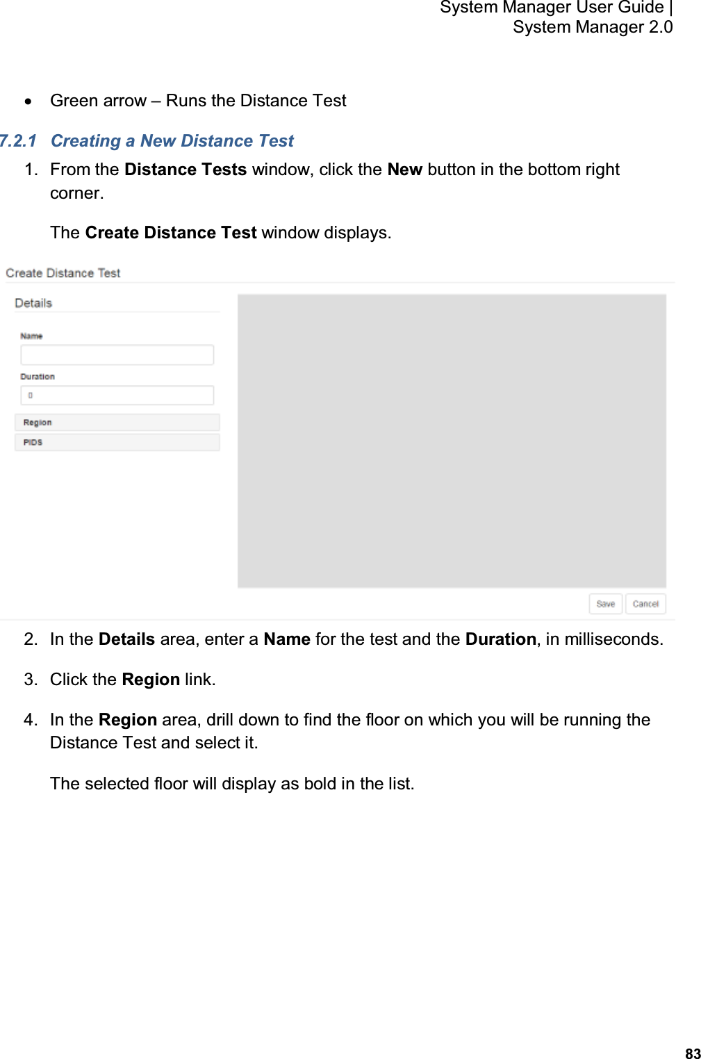
UserManual.wiki
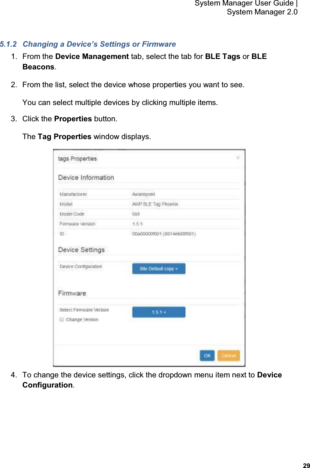
>
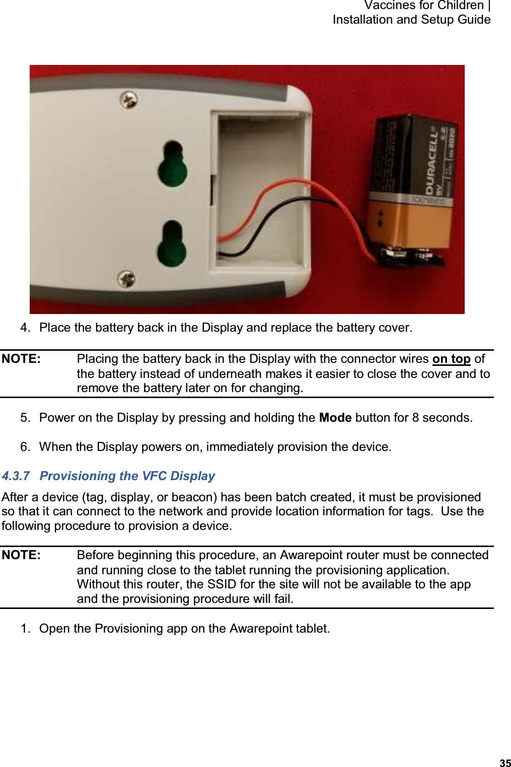
AwarePoint
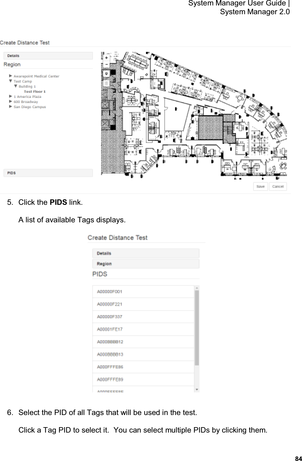
>
BLET User Manual
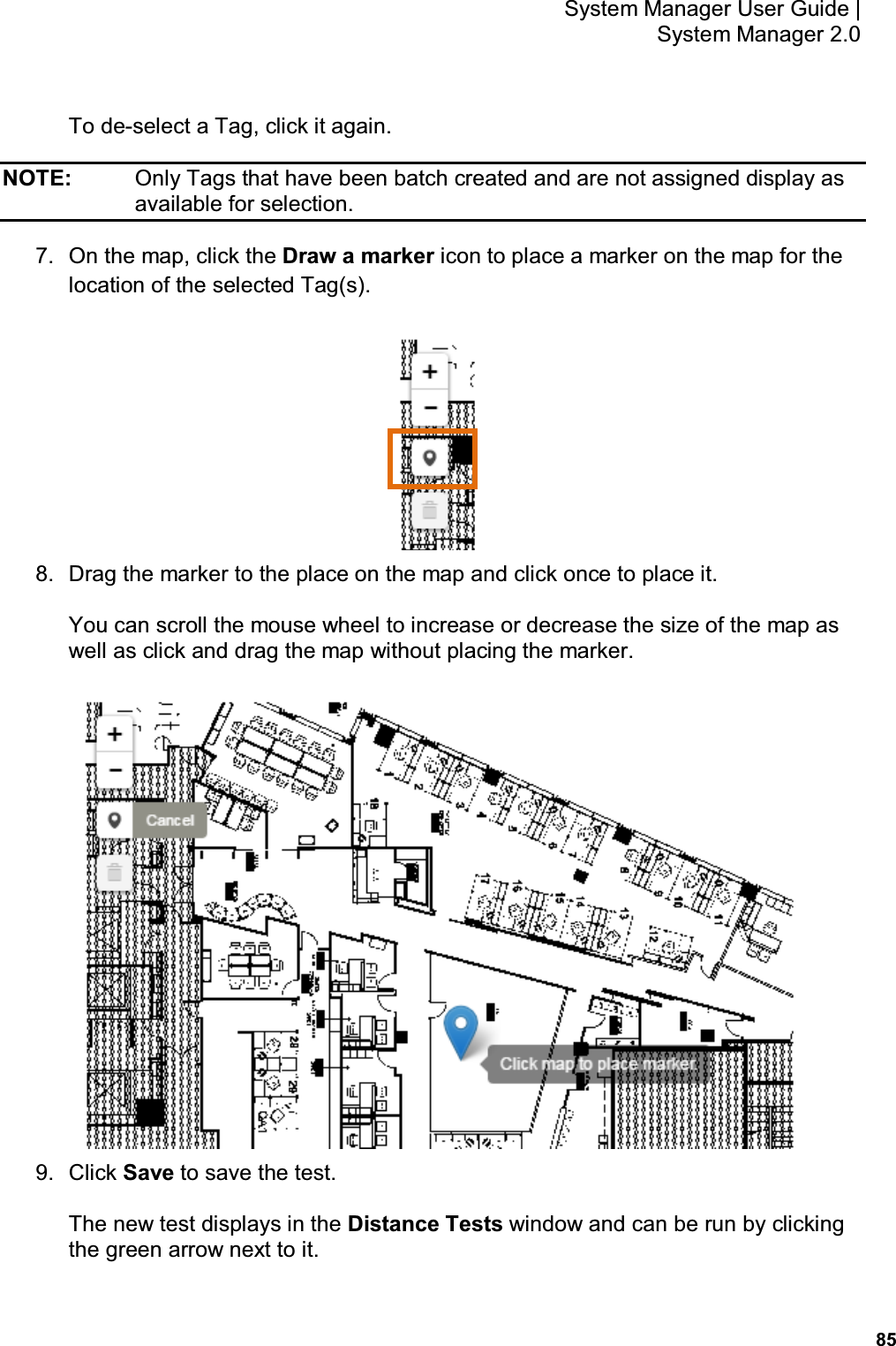
User Manual
Navigation menu
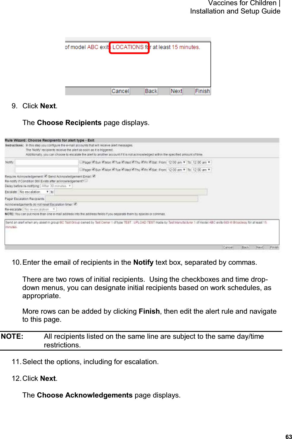
Upload a User Manual
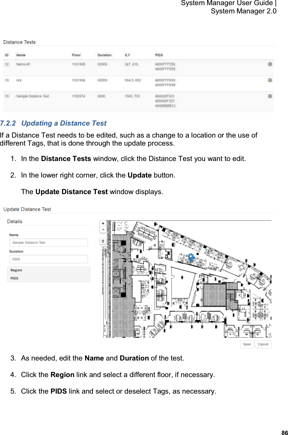
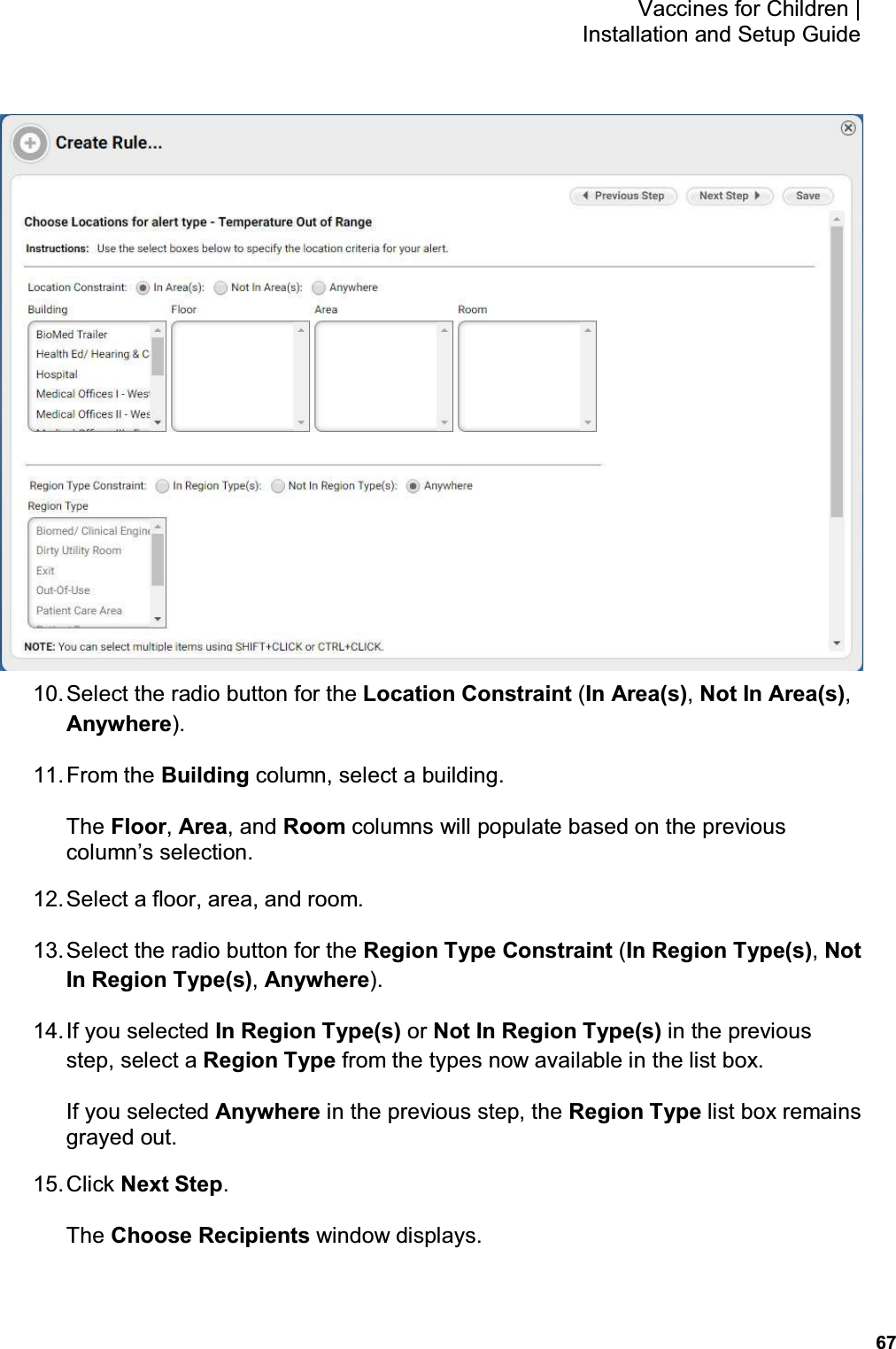
Namespaces
Wiki Guide
HTML
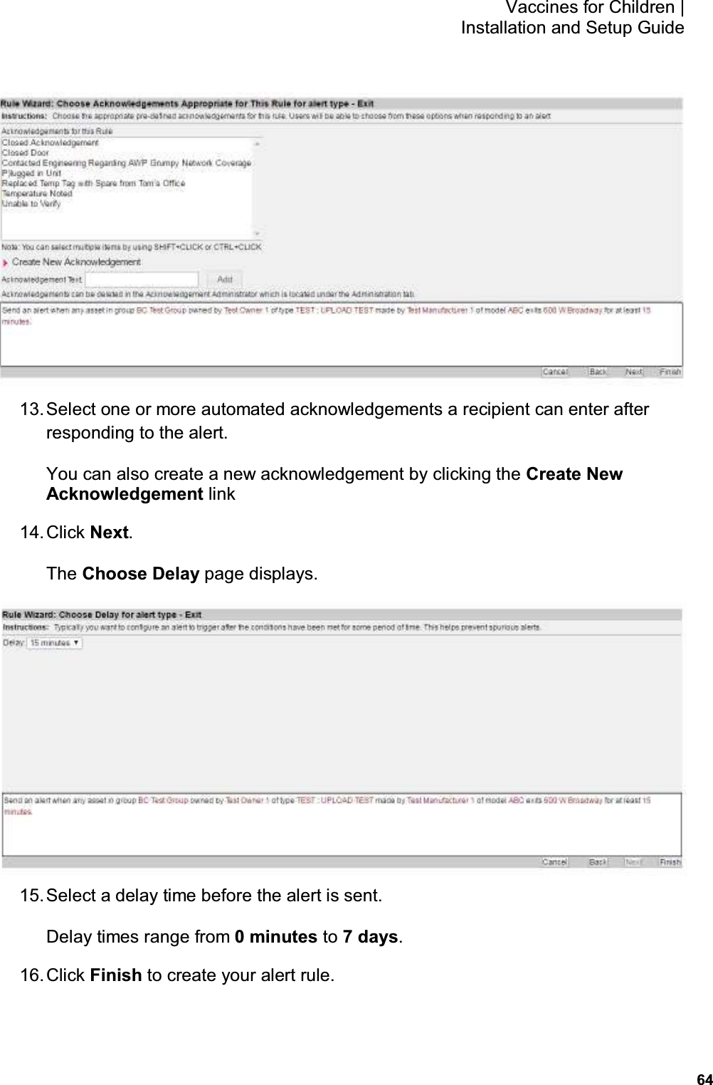
PDF
Info
Views
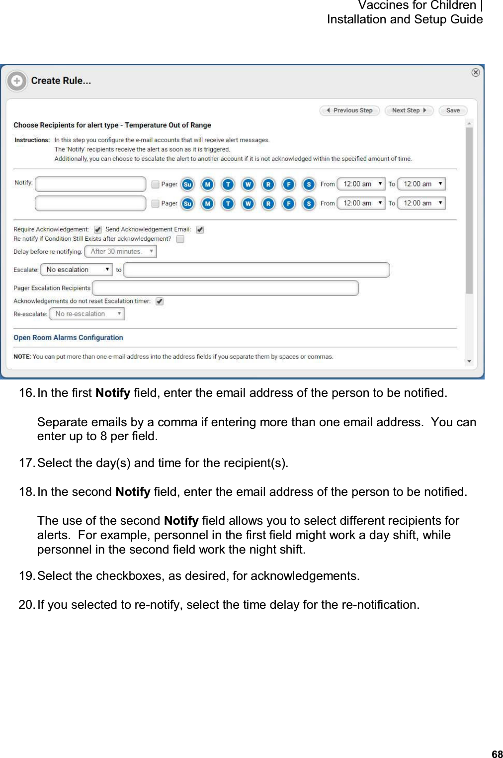
User Manual
Discussion / Help
Navigation

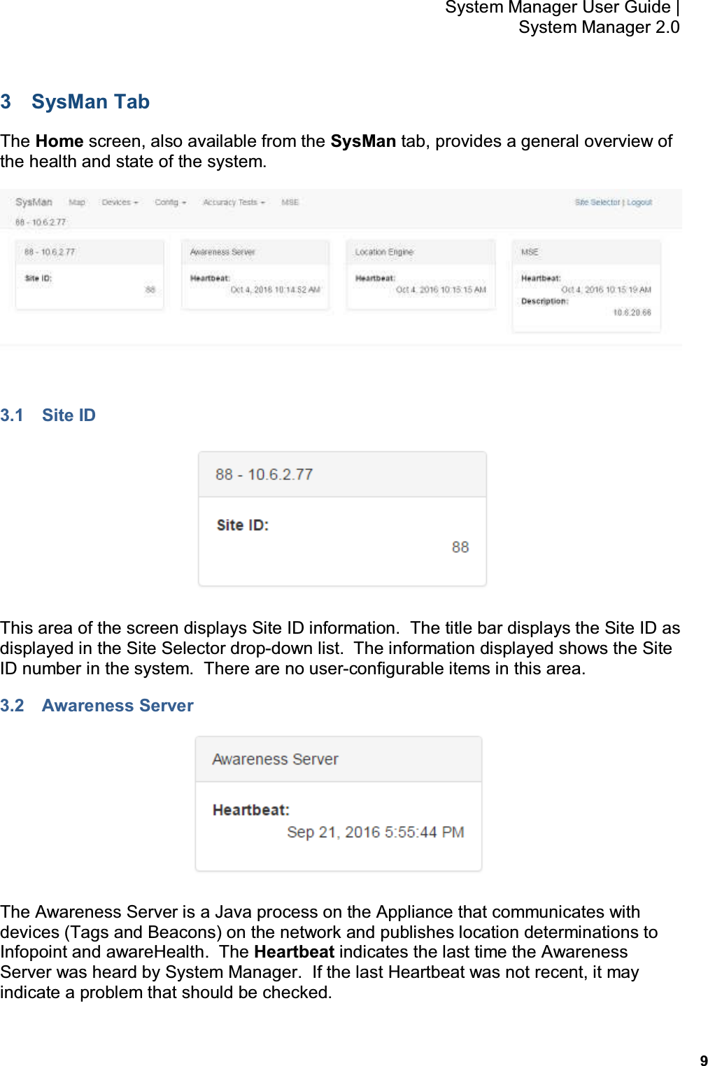
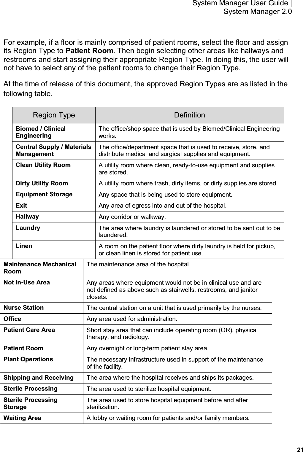
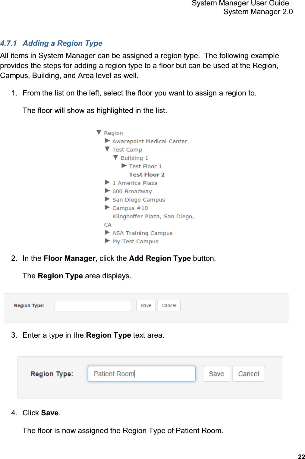
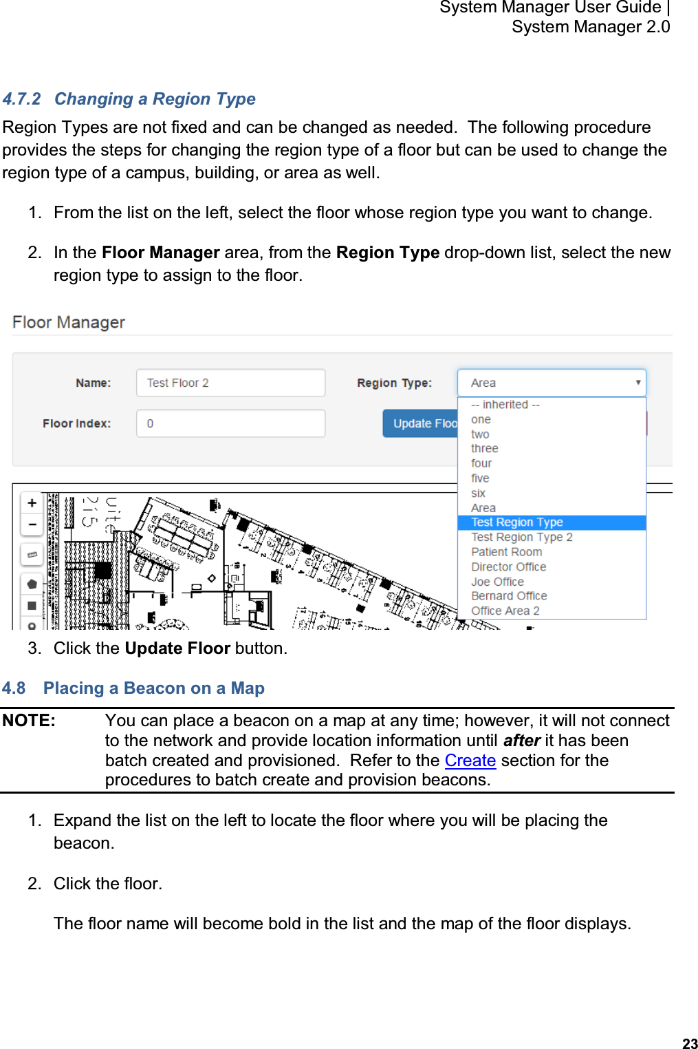
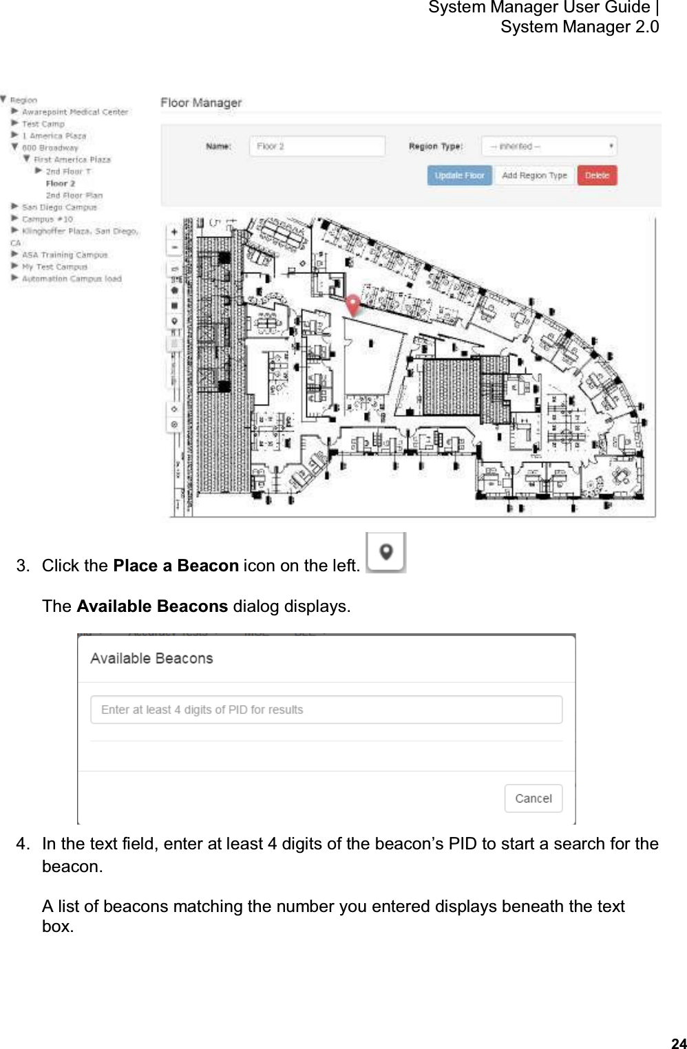


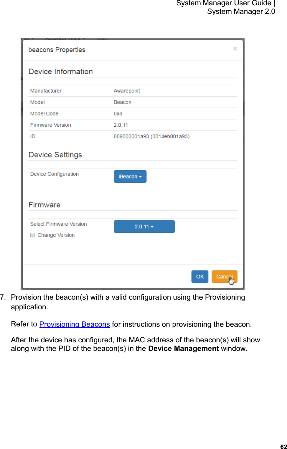
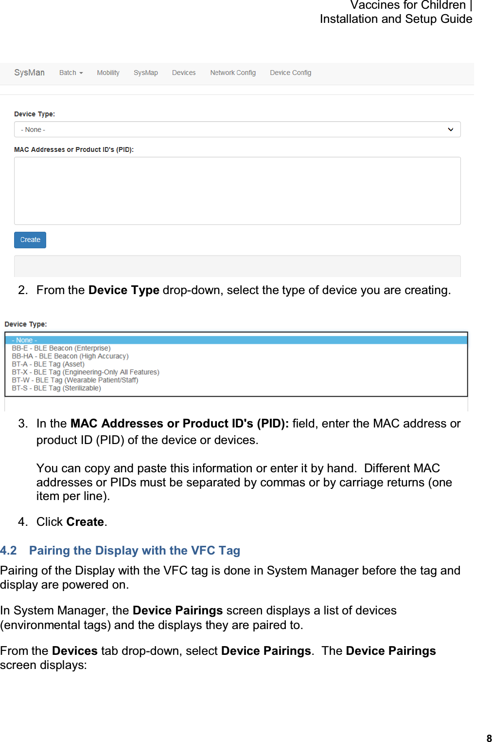
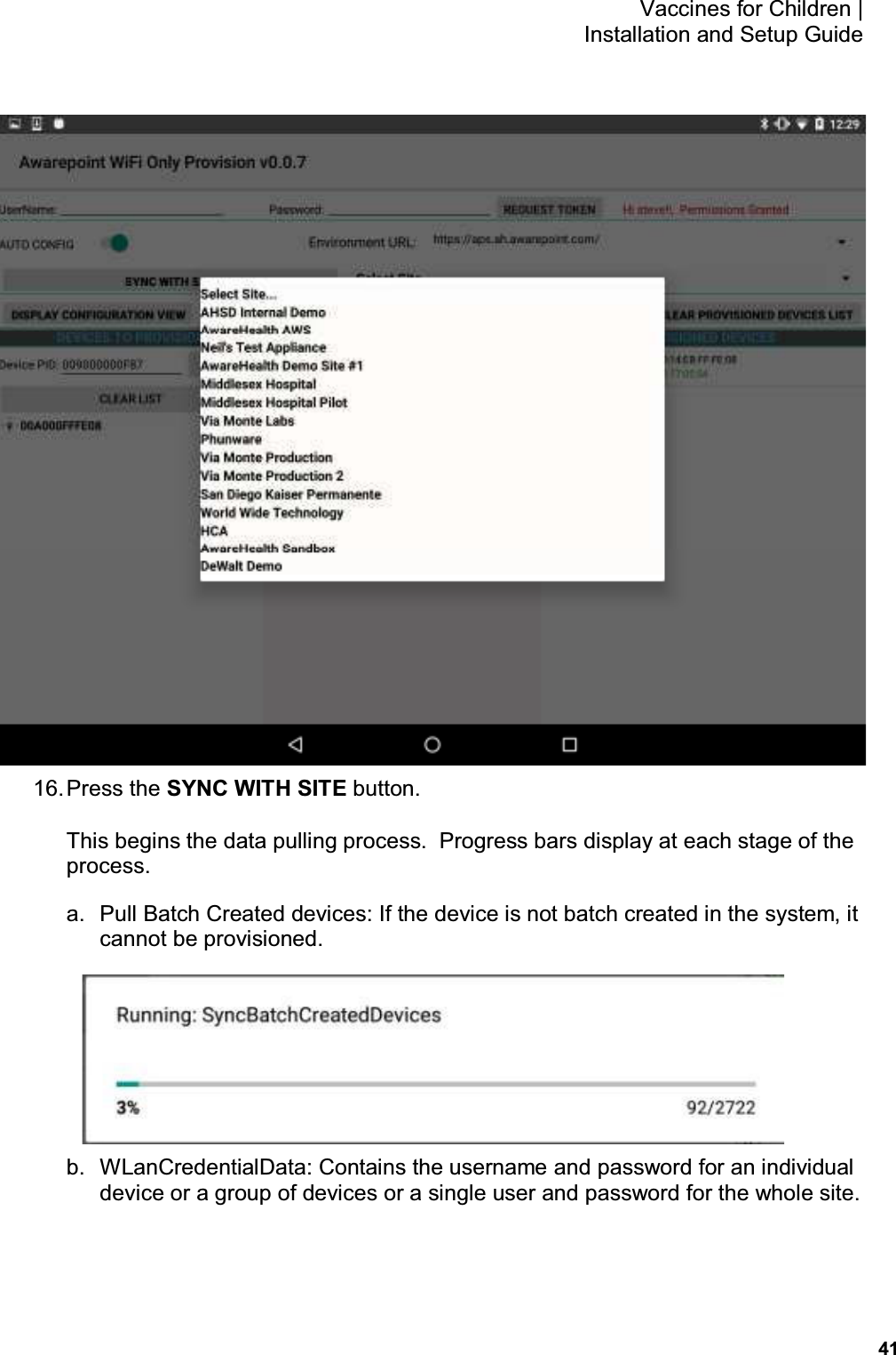
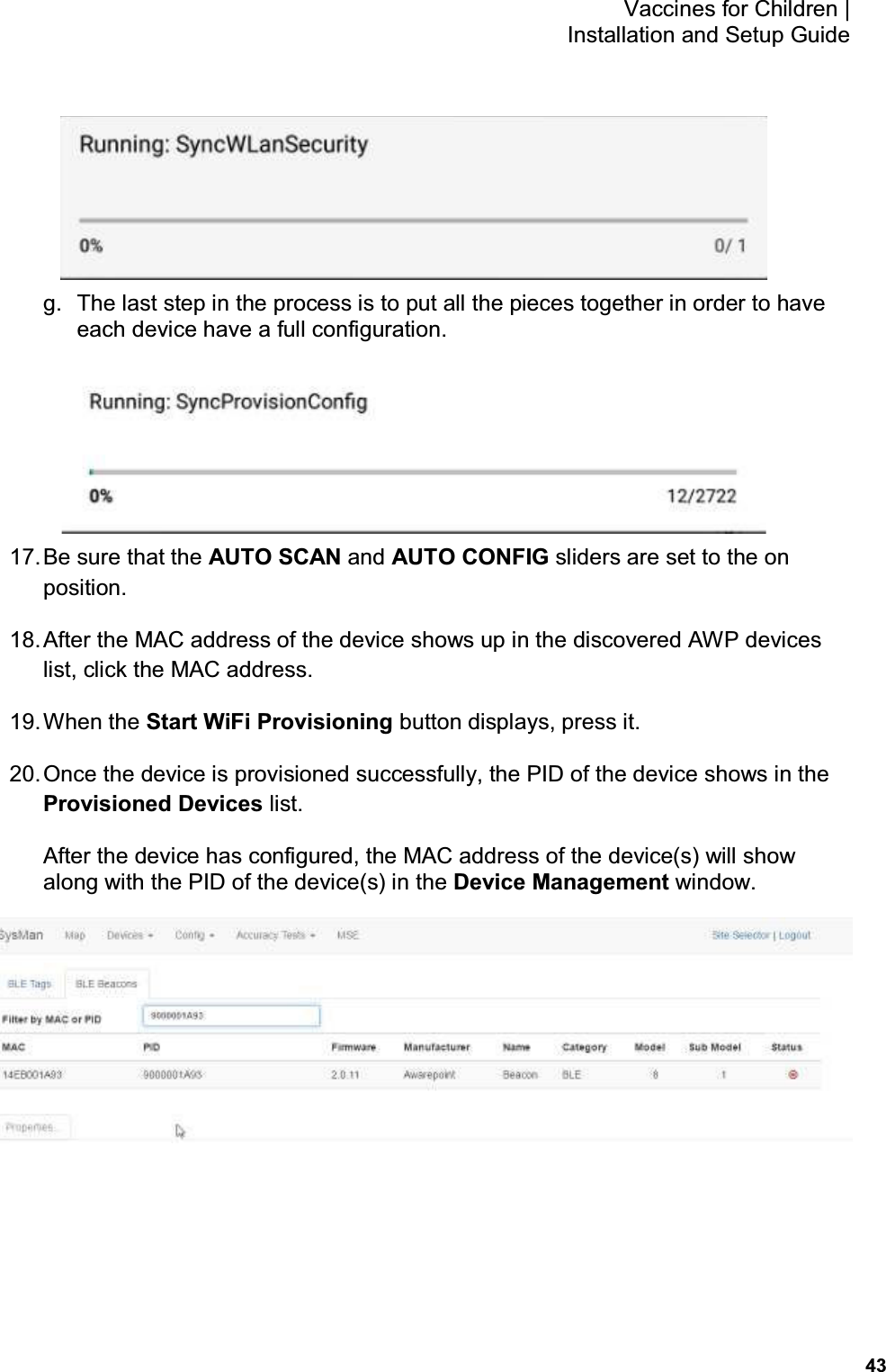
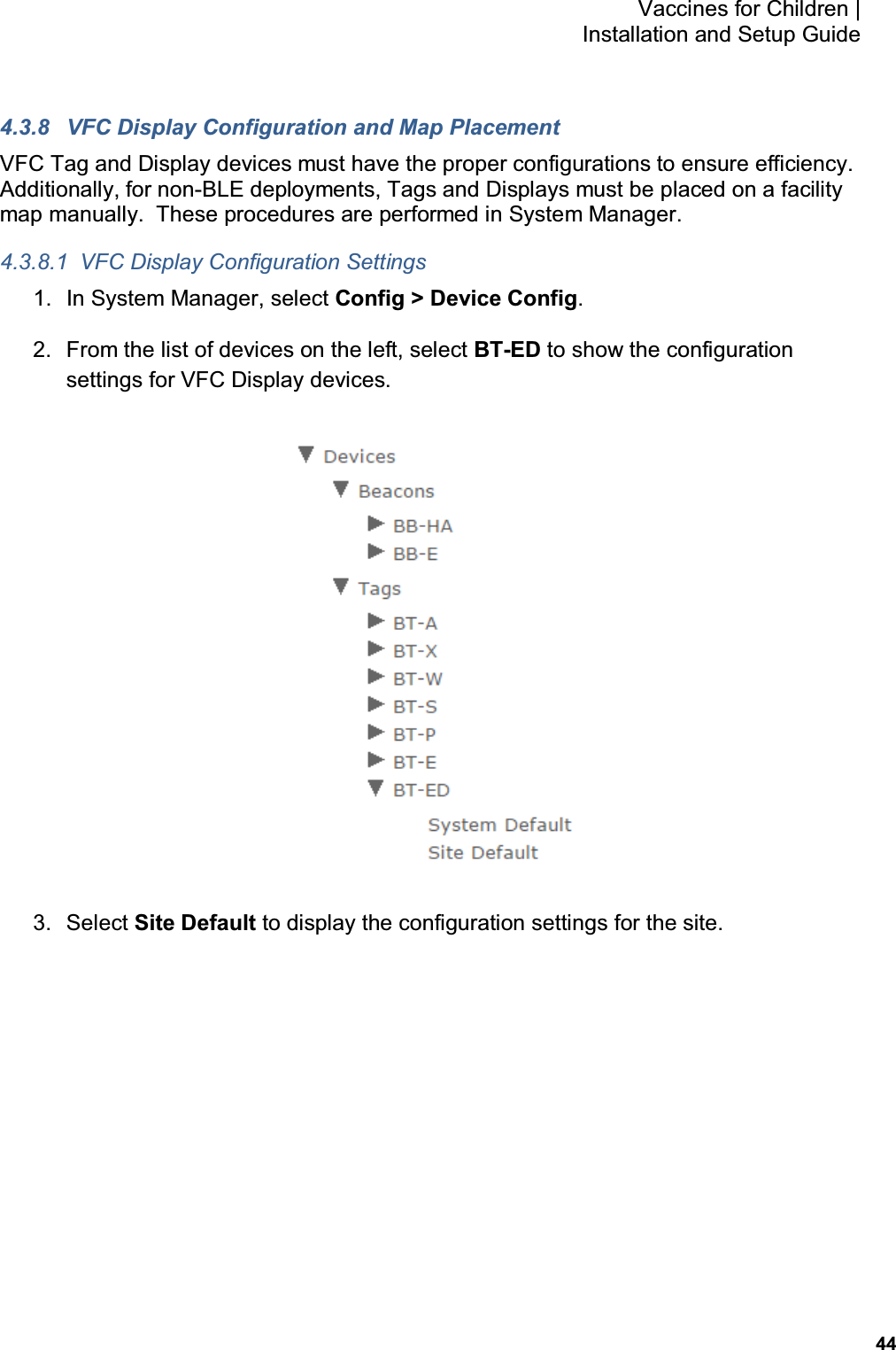
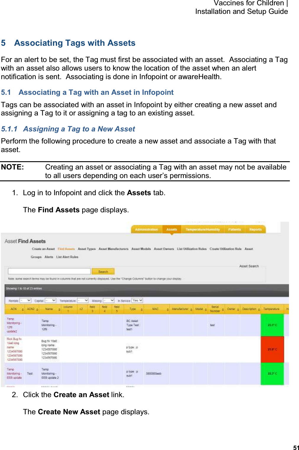
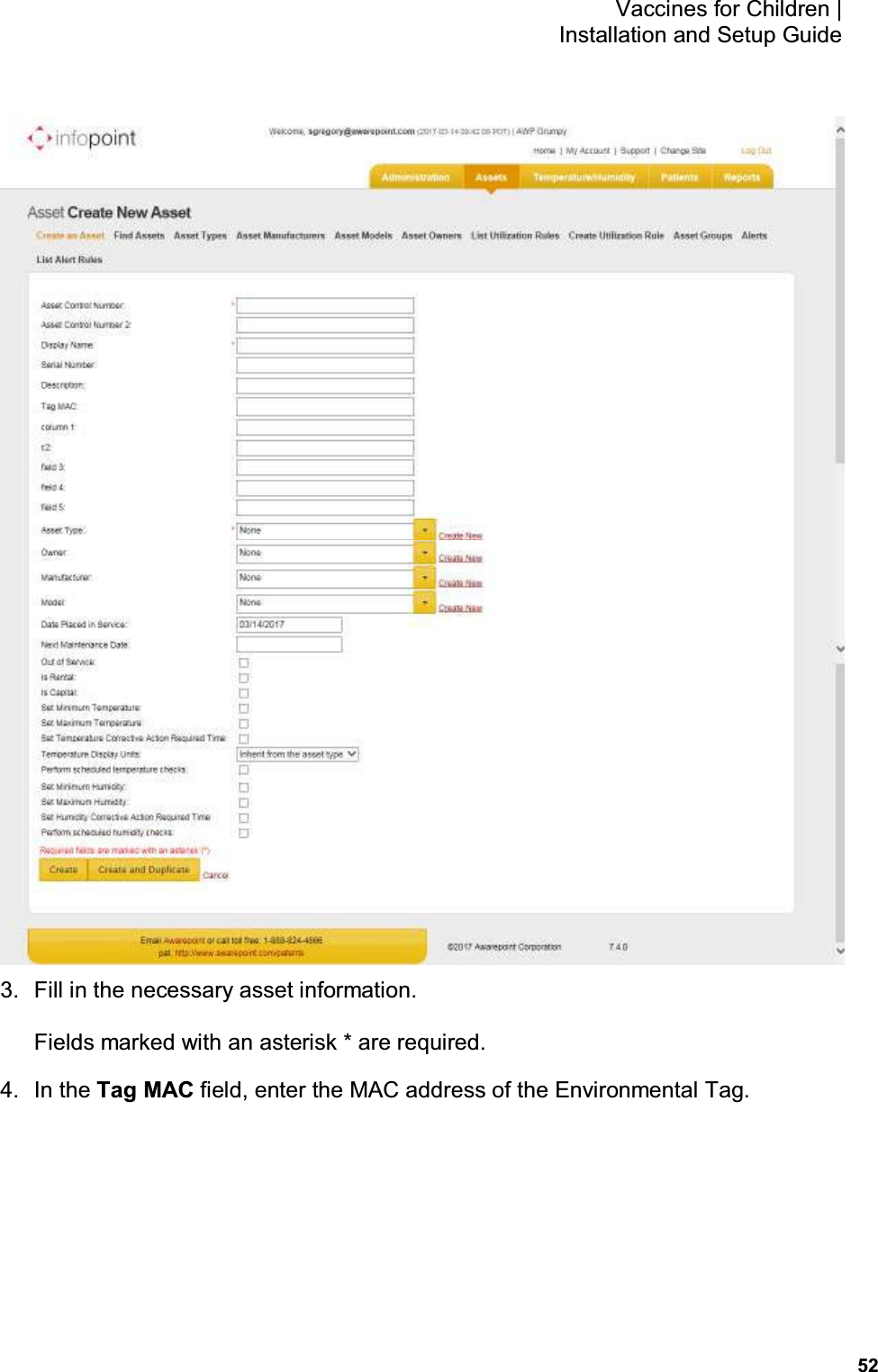
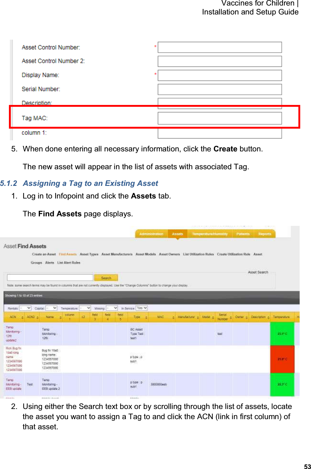
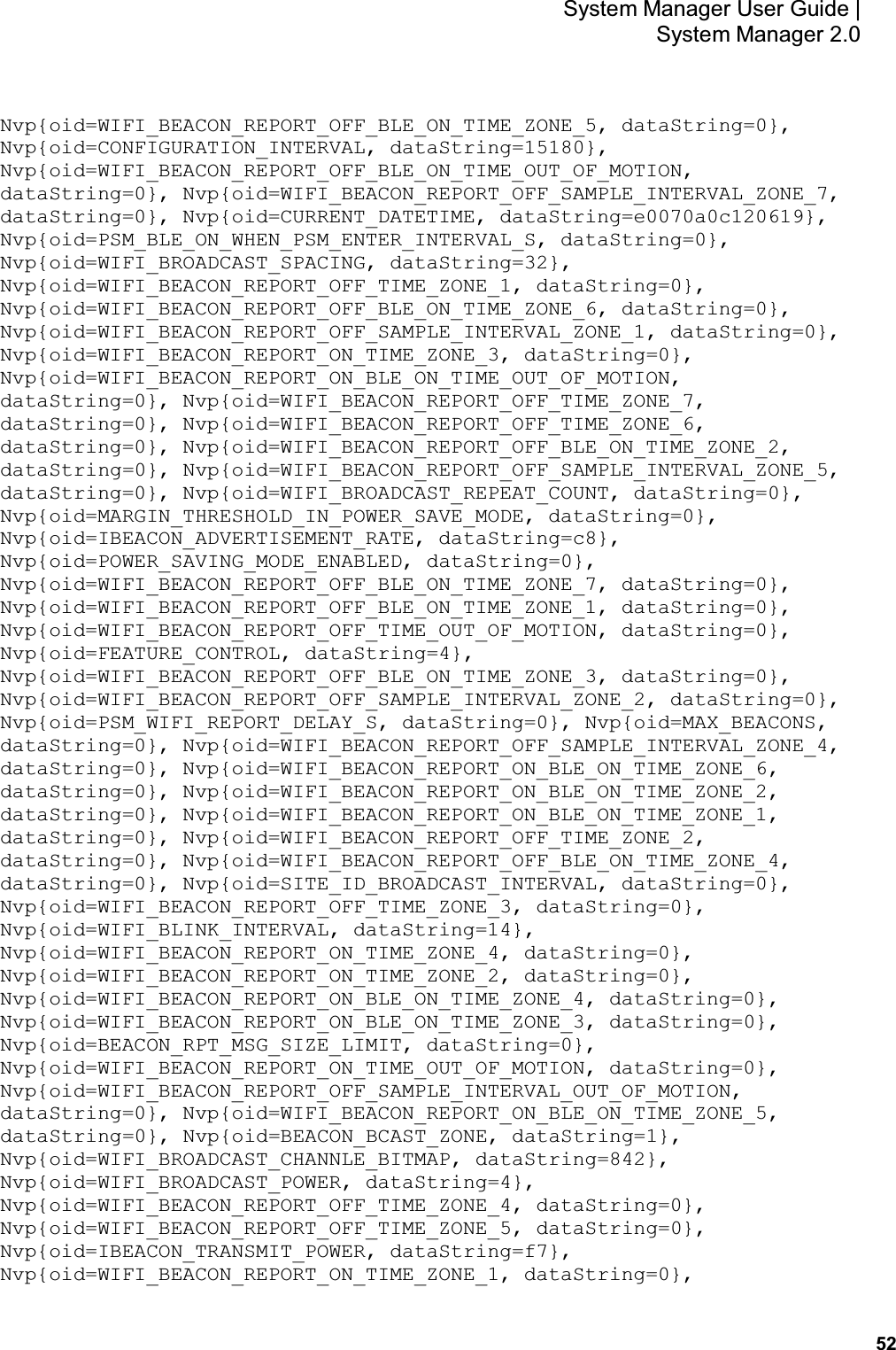
![51 System Manager User Guide | System Manager 2.0 g. The last step in the process is to put all the pieces together in order to have each device have a full configuration. 17. Be sure that the AUTO SCAN and AUTO CONFIG sliders are set to the on position. 18. After the MAC address of the beacon shows up in the discovered AWP devices list, click the MAC address. 19. When the Start WiFi Provisioning button displays, press it. 20. Once the beacon is provisioned successfully, the PID of the beacon shows in the Provisioned Devices list. During the provisioning process you can monitor the awarepoint.log file on the appliance using the following command: tail -F /var/log/tomcat/awarepoint.log| grep -i 'configuration\|error\|exception'| grep -vi 'mse\|pong\| mapHierarchyString' When the device is configured you should be able to see a configuration message similar to the following sent back to the device: 2016-10-12 11:06:25,752 [BleWifiActorSystem-akka.actor.default-dispatcher-13] DEBUG com.awarepoint.blewifiserver.infrastructure.actors.ble.ConfigurationHandler - sendConfigurationResponse EncodeResponse{mac=89842000652, hexMac='14EB00230C', message=Message{header=BleHeader{version=4, messageType=CONFIGURATION, mac=89842000652, hexMac='14EB00230C', ackRequested=true}, body=Configuration{nvpList=[Nvp{oid=WIFI_BEACON_REPORT_OFF_SAMPLE_INTERVAL_ZONE_6, dataString=0},](https://usermanual.wiki/AwarePoint/BLET/User-Guide-3382517-Page-52.png)
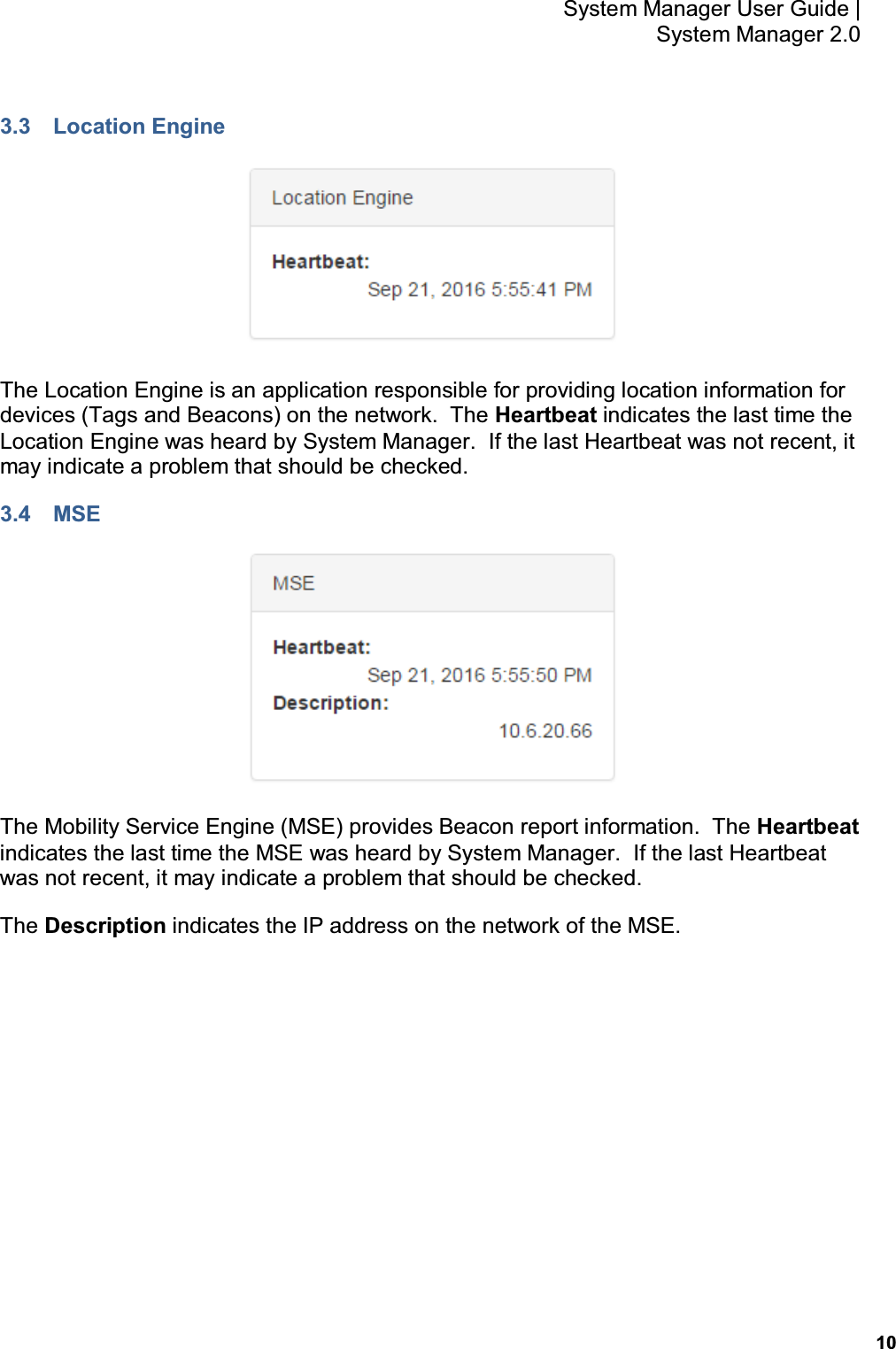
![53 System Manager User Guide | System Manager 2.0 Nvp{oid=WIFI_BEACON_REPORT_ON_TIME_ZONE_5, dataString=0}, Nvp{oid=BEACON_SITE_ID, dataString=56}, Nvp{oid=WIFI_BEACON_REPORT_ON_TIME_ZONE_6, dataString=0}, Nvp{oid=WIFI_BEACON_REPORT_ON_BLE_ON_TIME_ZONE_7, dataString=0}, Nvp{oid=WIFI_UNICAST_POWER, dataString=4}, Nvp{oid=WIFI_BEACON_REPORT_ON_TIME_ZONE_7, dataString=0}, Nvp{oid=WIFI_BEACON_REPORT_OFF_SAMPLE_INTERVAL_ZONE_3, dataString=0}], queryList=[]}}} After the device has configured, the MAC address of the beacon(s) will show along with the PID of the beacon(s) in the Device Management window. 5.6 Delete 1. From the Devices tab drop-down, select Delete. The Batch Delete screen displays. 2. In the MAC Addresses or Product ID's (PID): field, enter the MAC address or product ID (PID) of the device or devices to be deleted from the system. You can copy and paste this information or enter it by hand. Different MAC addresses or PIDs must be separated by commas or by carriage returns (one item per line). 3. Click Delete.](https://usermanual.wiki/AwarePoint/BLET/User-Guide-3382517-Page-54.png)