Axell Wireless 50-1184800 Tunnel Radio Bi directional 800MHz amplifier User Manual Weehawken 800
Axell Wireless Tunnel Radio Bi directional 800MHz amplifier Weehawken 800
User manual

Weehawken Tunnel 800MHz Repeater
User/Maintenance Handbook
Handbook N.-Weehawken_800 Issue No:-A
Date:-05/08/05 Page:-1 of 51
Weehawken Tunnel Radio
800MHz Repeater System
User/Maintenance Handbook
For
G.E Transport Systems
AFL Works Order N.: Q112727
AFL product part N.’s: 50-118401 (800MHz CCE)
80-231302 (800MHz Power Supply)
80-231303 (Alarm System)

Weehawken Tunnel 800MHz Repeater
User/Maintenance Handbook
Handbook N.-Weehawken_800 Issue No:-A
Date:-05/08/05 Page:-2 of 51
Table of Contents
INTRODUCTION ............................................................................................................................................5
Scope................................................................................................................................................................................ 5
Purpose............................................................................................................................................................................ 5
Glossary of Terms .......................................................................................................................................................... 7
Key to AFL RF Module Drawing Symbols.................................................................................................................. 8
1. SAFETY CONSIDERATIONS ............................................................................................................9
1.1 Earthing of Equipment ..................................................................................................................................... 9
1.2 Electric Shock Hazard ......................................................................................................................................9
1.3 RF Radiation Hazard...................................................................................................................................... 10
1.4 Chemical Hazard............................................................................................................................................. 11
1.5 Emergency Contact Numbers ........................................................................................................................ 11
2. OVERVIEW/ SYSTEM DESCRIPTION..........................................................................................12
2.1 General System Description ........................................................................................................................... 12
3. WEEHAWKEN RACK DRAWINGS................................................................................................13
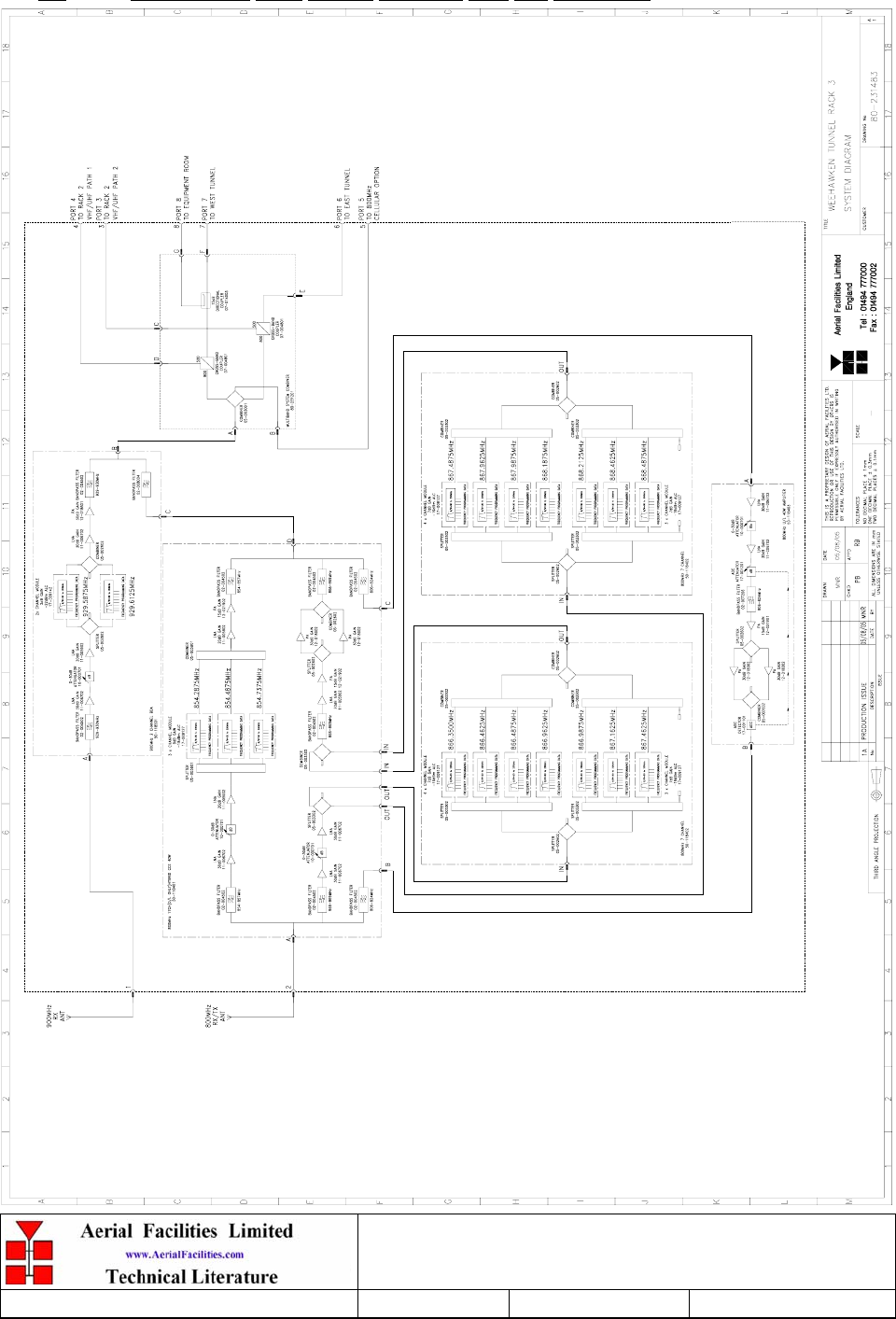
3.1 800/900MHz Rack System Diagram, Drg. Nō. 80-231483........................................................................... 13
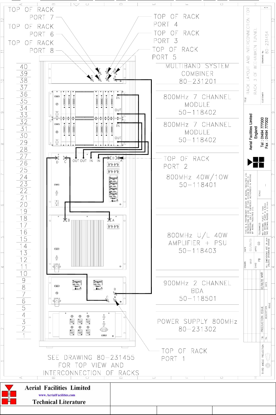
3.2 800/900MHz Rack Layout and Interconnections Diagram, Drg. Nō. 80-231454 ...................................... 14
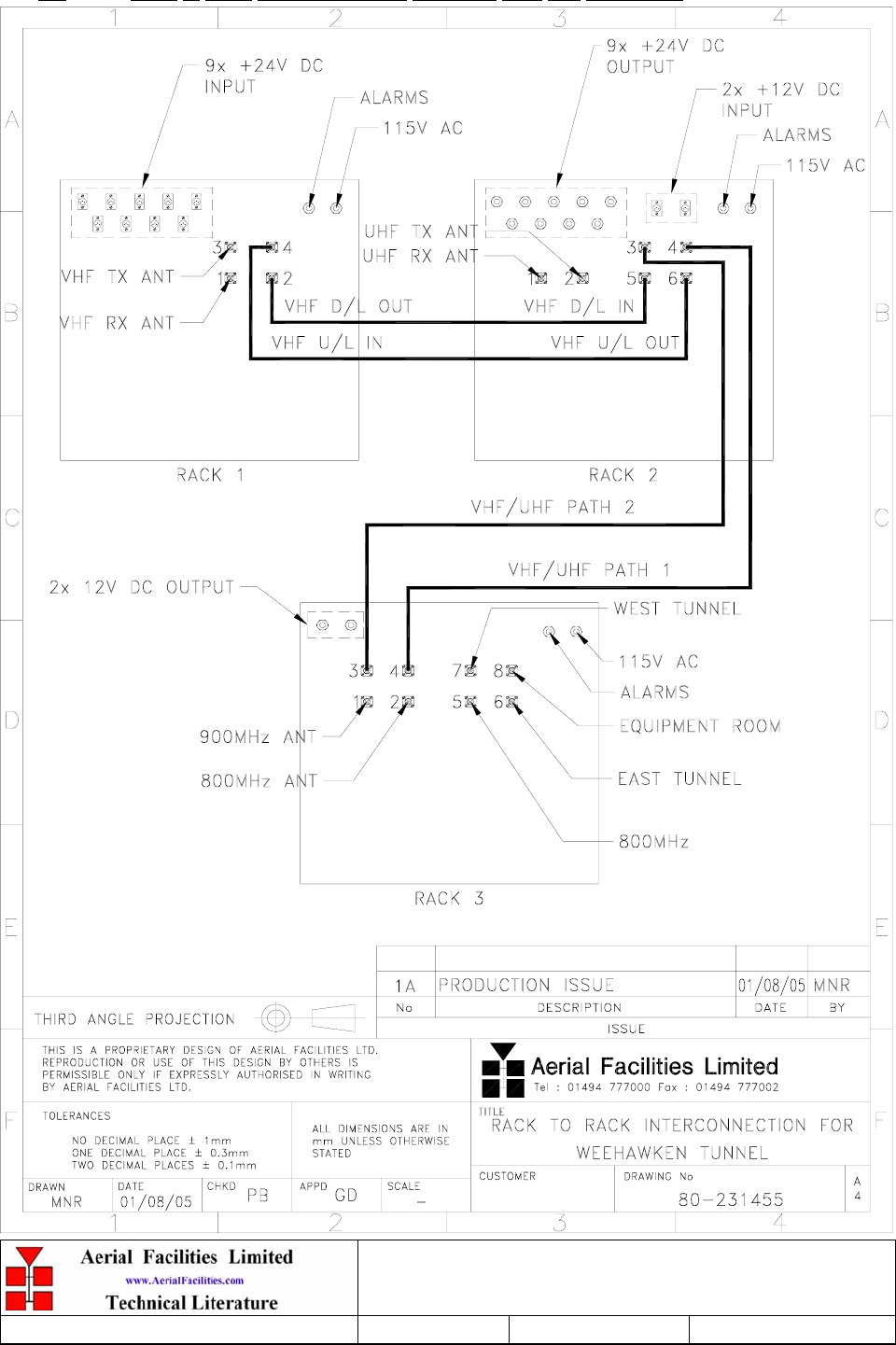
3.3 Rack to Rack Interconnections Diagram, Drg. Nō. 80-231455 ...................................................................15
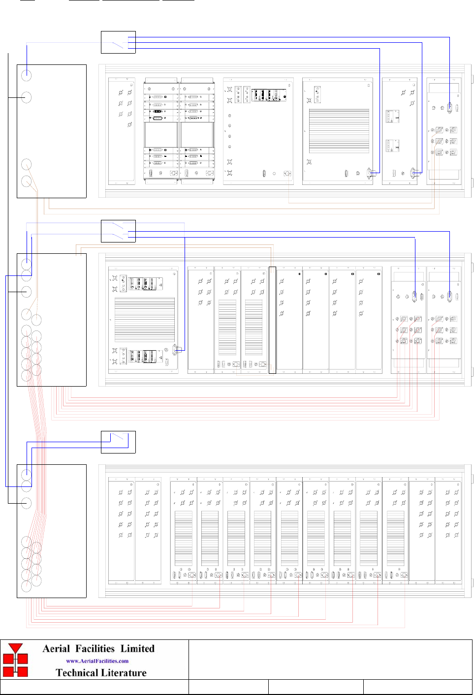
3.4 Power Distribution Sketch.............................................................................................................................. 16
3.5 Weehawken System Frequencies Look-up Table......................................................................................... 17
4. 800MHZ CELL ENHANCER (50-118401) .............................................................................................18
4.1 800MHz Cell Enhancer Description.............................................................................................................. 18
4.2 800MHz Cell Enhancer Technical Specification .......................................................................................... 18
4.3 800MHz Cell Enhancer System Diagram, Drg. Nō. 50-118481................................................................... 19
4.4 800MHz Seven Channel Module Shelf System Diagram, Drg. Nō. 50-118482.......................................... 20
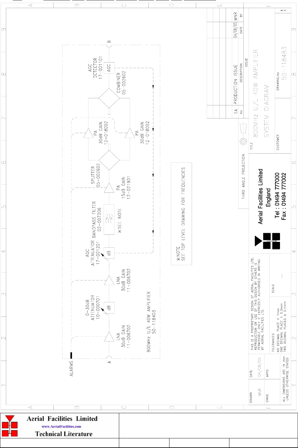
4.5 800MHz Cell Enhancer Uplink Path, Drg. Nō. 50-118483 .......................................................................... 21
4.6 800MHz Cell Enhancer Parts List................................................................................................................. 22
5. POWER SUPPLY & ALARMS..........................................................................................................23
5.1 800MHz Power Supply (80-231302) .............................................................................................................. 23
5.1.1 800MHz Power Supply Description.............................................................................................................. 23
5.1.2 800MHz Power Supply Technical Specification ........................................................................................... 23
5.1.3 800MHz Power Supply System Diagram ...................................................................................................... 23
5.1.4 800MHz Power Supply Outline Drawing, Drg. Nō. 80-231392 ...................................................................24
5.1.5 800MHz Power Supply Parts List ................................................................................................................. 25
5.2 Alarm/Monitor Shelf (80-231303).................................................................................................................. 26
5.2.1 Alarm/Monitor Shelf Description..................................................................................................................26
5.2.2 Alarm/Monitor Shelf Technical Specification ............................................................................................... 26
5.2.3 Alarm/Monitor Shelf Parts List ..................................................................................................................... 27
6. SUB-UNIT MODULES .......................................................................................................................28
6.1 Bandpass Filter (02-004502)........................................................................................................................... 28
6.1.1 Description.................................................................................................................................................... 28
6.1.2 Technical Specification ................................................................................................................................. 28
6.2 Bandpass Filter (02-007206)........................................................................................................................... 29
6.2.1 Description.................................................................................................................................................... 29
6.2.2 Technical Specification ................................................................................................................................. 29
6.7 900MHz Splitter/Combiner (05-002602)....................................................................................................... 30
6.7.1 Description.................................................................................................................................................... 30
6.7.2 Technical Specification ................................................................................................................................. 30
6.8 ¼Watt 0- -30 & 0-15dB Switched Attenuator (10-000701 & 10-000901)................................................... 31
6.8.1 General Application ......................................................................................................................................31
6.8.2 Switched Attenuators..................................................................................................................................... 31
6.9 Low Noise Amplifier (11-005902) .................................................................................................................. 32

Weehawken Tunnel 800MHz Repeater
User/Maintenance Handbook
Handbook N.-Weehawken_800 Issue No:-A
Date:-05/08/05 Page:-3 of 51
6.9.1 Description.................................................................................................................................................... 32
6.9.2 Technical Specification ................................................................................................................................. 32
6.10 Low Noise Amplifier (11-006702) .................................................................................................................. 33
6.10.1 Description................................................................................................................................................ 33
6.10.2 Technical Specification ............................................................................................................................. 33
6.11 20W Power Amplifier (12-018002) ................................................................................................................ 34
6.11.1 Description................................................................................................................................................ 34
6.11.2 Technical Specification ............................................................................................................................. 34
6.11.3 PA 7-Way Connector Pin-outs .................................................................................................................. 34
6.12 800MHz 1Watt Low Power Amplifier (12-021901)...................................................................................... 35
6.12.1 Description................................................................................................................................................ 35
6.12.2 Technical Specification ............................................................................................................................. 35
6.12.3 LPA 7-Way Connector Pin-outs................................................................................................................ 35
6.13 D.I.P Channel Control Module (17-002101) ................................................................................................. 36
6.13.1 Description................................................................................................................................................ 36
6.13.2 Programming Procedure ..........................................................................................................................37
6.13.3 12.5kHz step size switch functions ............................................................................................................37
6.13.4 25kHz step size switch functions ...............................................................................................................38
6.13.5 Programming Example .............................................................................................................................38
6.13.6 17-002101 Controller Module DIP Switch Connector Data .................................................................... 39
6.13.7 Drg. Nō. 17-002190, DIP Switch Module Controller Outline Drawing ................................................... 40
6.14 Channel Selective Modules (17-003033, 17-009143, 17-009127 & 17-010803)........................................... 41
6.14.1 Description................................................................................................................................................ 41
6.14.2 Drg. Nō. 17-003080, Generic Channel Module Block Diagram ..............................................................42
6.15 12 & 24V Dual Relay Boards (20-001601 & 20-001602)..............................................................................43
6.15.1 Description................................................................................................................................................ 43
6.15.2 Technical Specification ............................................................................................................................. 43
6.16 12 & 24V Single Relay Board (80-008901 & 80-008902) .............................................................................43
6.16.1 Description................................................................................................................................................ 43
9. INSTALLATION.................................................................................................................................44
9.1 General Remarks ............................................................................................................................................ 44
9.2 RF Connections ............................................................................................................................................... 45
9.3 Commissioning ................................................................................................................................................ 45
10. MAINTENANCE.................................................................................................................................46
10.1 Fault Finding ................................................................................................................................................... 46
10.1.1 Quick Fault Checklist................................................................................................................................46
10.1.2 Fault Isolation........................................................................................................................................... 46
10.1.3 Downlink ...................................................................................................................................................47
10.1.4 Uplink........................................................................................................................................................47
10.1.5 Checking service .......................................................................................................................................47
10.1.6 Fault repair ............................................................................................................................................... 48
10.1.7 Service Support .........................................................................................................................................48
10.2 Tools & Test Equipment................................................................................................................................. 48
10.3 Care of Modules .............................................................................................................................................. 49
10.3.1 General Comments....................................................................................................................................49
10.3.2 Module Removal (LNA’s, general procedure):......................................................................................... 49
10.3.3 Module Replacement (general):................................................................................................................49
10.3.4 Power Amplifiers.......................................................................................................................................49
10.3.5 Low Power Amplifier Replacement........................................................................................................... 50
10.3.6 Module Transportation: ............................................................................................................................ 50
APPENDIX A INITIAL EQUIPMENT SET-UP CALCULATIONS ....................................................51

Weehawken Tunnel 800MHz Repeater
User/Maintenance Handbook
Handbook N.-Weehawken_800 Issue No:-A
Date:-05/08/05 Page:-4 of 51
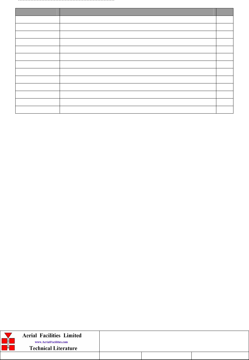
AMENDMENT LIST RECORD SHEET
Issue
Nō.
Date Incorporated
by
Page No.’s
Amended
Reason for new issue
A 05/09/2005 CMH 1st Draft
1 CMH 1st Issue
Document Ref:-80-231401HBKM

Weehawken Tunnel 800MHz Repeater
User/Maintenance Handbook
Handbook N.-Weehawken_800 Issue No:-A
Date:-05/08/05 Page:-5 of 51
INTRODUCTION
Scope
This handbook is for use solely with the equipment identified by the AFL Part Number shown
on the front cover. It is not to be used with any other equipment unless specifically authorised
by Aerial Facilities Limited.
Purpose
The purpose of this handbook is to provide the user/maintainer with sufficient information to
service and repair the equipment to the level agreed. Maintenance and adjustments to any
deeper level must be performed by AFL, normally at the company’s repair facility in Chesham,
England.
This handbook has been prepared in accordance with BS 4884, and AFL’s Quality procedures,
which maintain the company’s registration to BS EN ISO 9001:2000 and to the R&TTE
Directive of the European Parliament. Copies of the relevant certificates and the company
Quality Manual can be supplied on application to the Quality Manager.
This document fulfils the relevant requirements of Article 6 of the R&TTE Directive.
Limitation of Information Notice
This manual is written for the use of technically competent operators/service persons. No
liability is accepted by AFL for use or misuse of this manual, the information contained
therein, or the consequences of any actions resulting from the use of the said information,
including, but not limited to, descriptive, procedural, typographical, arithmetical, or listing
errors.
Furthermore, AFL does not warrant the absolute accuracy of the information contained within
this manual, or it’s completeness, fitness for purpose, or scope.
AFL has a policy of continuous product development and enhancement, and as such, reserves
the right to amend, alter, update and generally change the contents, appearance and pertinence
of this document without notice.
All AFL products carry a twelve month warranty from date of shipment. The warranty is
expressly on a return to base repair or exchange basis and the warranty cover does not extend
to on-site repair or complete unit exchange.

Weehawken Tunnel 800MHz Repeater
User/Maintenance Handbook
Handbook N.-Weehawken_800 Issue No:-A
Date:-05/08/05 Page:-6 of 51
EC DECLARATION OF CONFORMITY
In accordance with BS EN ISO/IEC 17050-1&-2:2004
AERIAL FACILITIES LTD
Aerial House
Asheridge Road
Chesham
Bucks HP5 2QD
United Kingdom
DECLARES, UNDER OUR SOLE RESPONSIBILITY THAT THE FOLLOWING PRODUCT
PRODUCT PART NO[S] 80-231401
PRODUCT DESCRIPTION Weehawken tunnel amplifier system
IN ACCORDANCE WITH THE FOLLOWING DIRECTIVES:
1999/5/EC The Radio & Telecommunications Terminal Equipment Directive Annex V and its amending
directives
HAS BEEN DESIGNED AND MANUFACTURED TO THE FOLLOWING STANDARD[S] OR OTHER
NORMATIVE DOCUMENT[S]:
BS EN 60950 Information technology equipment. Safety. General requirements
ETS EN 301 489-1 EMC standard for radio equipment and services. Part 1. Common technical
requirements
I hereby declare that the equipment named above has been designed to comply with the relevant sections of the
above referenced specifications. The unit complies with all essential requirements of the Directives.
SIGNED
B S BARTON
TECHNICAL DIRECTOR DATE: 08/11/2005
0086

Weehawken Tunnel 800MHz Repeater
User/Maintenance Handbook
Handbook N.-Weehawken_800 Issue No:-A
Date:-05/08/05 Page:-7 of 51
Glossary of Terms
Repeater or
Cell Enhancer A Radio Frequency (RF) amplifier which can simultaneously
amplify and re-broadcast Mobile Station (MS) and Base
Transceiver Station (BTS) signals.
Band Selective Repeater A Cell Enhancer designed for operation on a range of channels
within a specified frequency band.
Channel Selective
Repeater A Cell Enhancer, designed for operation on specified
channel(s) within a specified frequency band. Channel
frequencies may be factory set or on-site programmable.
AC Alternating Current
AGC Automatic Gain Control
BBU Battery Backup Unit
BTS Base Transceiver Station
CEMS Coverage Enhanced Management System
C/NR Carrier-to-Noise Ratio
DC Direct Current
Downlink (D/L) RF signals Tx from the BTS to the Master Site
FO Fibre Optic
GND Ground
ID Identification Number
LED Light Emitting Diode
LNA Low Noise Amplifier
LPA Low Power Amplifier
MOU Master Optical Unit
M.S. Mobile Station
MTBF Mean Time Between Failures
N/A Not Applicable
N/C No Connection
OFR On Frequency Repeater
OIP3 Output Third Order Intercept Point = RFout +(C/I)/2
PA Power Amplifier
RF Radio Frequency
RSA Receiver/Splitter Amplifier
Rx Receiver
S/N Serial Number
Tx Transmitter
Uplink (U/L) RF signals transmitted from the MS to the BTS
VSWR Voltage Standing Wave Ratio
WDM Wave division multiplex
Weehawken Tunnel 800MHz Repeater
User/Maintenance Handbook
Handbook N.-Weehawken_800 Issue No:-A
Date:-05/08/05 Page:-8 of 51
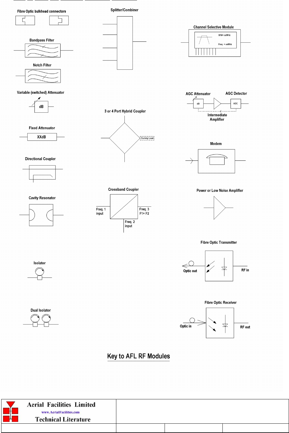
Key to AFL RF Module Drawing Symbols
Weehawken Tunnel 800MHz Repeater
User/Maintenance Handbook
Handbook N.-Weehawken_800 Issue No:-A
Date:-05/08/05 Page:-9 of 51
1. SAFETY CONSIDERATIONS
1.1 Earthing of Equipment
Cell Enhancers supplied from the mains must be connected to grounded outlets and earthed in
conformity with appropriate local, national and international electricity supply and safety
regulations.
1.2 Electric Shock Hazard
Electrical shocks due to faulty mains driven power supplies.
Whilst ever potentially present in any electrical equipment, such a condition would be
minimised by quality installation practice and thorough testing at:
a) Original assembly
b) Commissioning
c) Regular intervals, thereafter.
All test equipment to be in good working order prior to its use. High current power supplies can
be dangerous because of the possibility of substantial arcing. Always switch off during
disconnection and reconnection.
Weehawken Tunnel 800MHz Repeater
User/Maintenance Handbook
Handbook N.-Weehawken_800 Issue No:-A
Date:-05/08/05 Page:-10 of 51
1.3 RF Radiation Hazard
RF radiation, (especially at UHF frequencies) arising from transmitter outputs connected to
AFL’s equipment, must be considered a safety hazard.
This condition might only occur in the event of cable disconnection, or because a ‘spare’ output
has been left unterminated. Either of these conditions would impair the system’s efficiency. No
investigation should be carried out until all RF power sources have been removed. This would
always be a wise precaution, despite the severe mismatch between the impedance of an N type
connector at 50, and that of free space at 377, which would severely mitigate against the
efficient radiation of RF power. Radio frequency burns could also be a hazard, if any RF power
carrying components were to be carelessly touched!
Antenna positions should be chosen to comply with requirements (both local & statutory)
regarding exposure of personnel to RF radiation. When connected to an antenna, the unit is
capable of producing RF field strengths, which may exceed guideline safe values especially if
used with antennas having appreciable gain. In this regard the use of directional antennas with
backscreens and a strict site rule that personnel must remain behind the screen while the RF
power is on, is strongly recommended.
Where the equipment is used near power lines, or in association with temporary masts not
having lightning protection, the use of a safety earth connected to the case-earthing bolt is
strongly advised.
Weehawken Tunnel 800MHz Repeater
User/Maintenance Handbook
Handbook N.-Weehawken_800 Issue No:-A
Date:-05/08/05 Page:-11 of 51
1.4 Chemical Hazard
Beryllium Oxide, also known as Beryllium Monoxide, or Thermalox™, is sometimes used in
devices within equipment produced by Aerial Facilities Ltd. Beryllium oxide dust can be toxic if
inhaled, leading to chronic respiratory problems. It is harmless if ingested or by contact.
Products that contain beryllium are load terminations (dummy loads) and some power
amplifiers. These products can be identified by a yellow and black “skull and crossbones”
danger symbol (shown above). They are marked as hazardous in line with international
regulations, but pose no threat under normal circumstances. Only if a component containing
beryllium oxide has suffered catastrophic failure, or exploded, will there be any danger of the
formation of dust. Any dust that has been created will be contained within the equipment
module as long as the module remains sealed. For this reason, any module carrying the yellow
and black danger sign should not be opened. If the equipment is suspected of failure, or is at the
end of its life-cycle, it must be returned to Aerial Facilities Ltd for disposal.
To return such equipment, please contact the Quality Department, who will give you a Returned
Materials Authorisation (RMA) number. Please quote this number on the packing documents,
and on all correspondence relating to the shipment.
PolyTetraFluoroEthylene, (P.T.F.E.) and P.T.F.E. Composite Materials
Many modules/components in AFL equipment contain P.T.F.E. as part of the RF insulation
barrier.
This material should never be heated to the point where smoke or fumes are evolved. Any
person feeling drowsy after coming into contact with P.T.F.E. especially dust or fumes should
seek medical attention.
1.5 Emergency Contact Numbers
The AFL Quality Department can be contacted on:
Telephone +44 (0)1494 777000
Fax +44 (0)1494 777002
e-mail qa@aerial.co.uk

Weehawken Tunnel 800MHz Repeater
User/Maintenance Handbook
Handbook N.-Weehawken_800 Issue No:-A
Date:-05/08/05 Page:-12 of 51
2. OVERVIEW/ SYSTEM DESCRIPTION
2.1 General System Description
The Weehawken tunnel radio system is designed to amplify various bands of radio frequencies,
in either channelised or band selective modes. All the hardware is built into standard 19” rack
mounted cabinets which have an environmental IP rating of 54.
The systems in this document will be described as individual shelves (800MHz and 900MHz
Pager) and the various passive combiners, splitters and cross-band coupler shelves will also be
described in separate documents. Every active module in the entire system has a dedicated
alarm and these are series wired within the shelves to a relay which gives a volt-free output pair
for each shelf which is wired to a ‘krone-block’ termination in the rack cabinet. The
800/900MHz repeater system has its own dedicated mains driven power supply.
Weehawken Tunnel 800MHz Repeater
User/Maintenance Handbook
Handbook N.-Weehawken_800 Issue No:-A
Date:-05/08/05 Page:-13 of 51
3. WEEHAWKEN RACK DRAWINGS
3.1 800/900MHz Rack System Diagram, Drg. N. 80-231483
Weehawken Tunnel 800MHz Repeater
User/Maintenance Handbook
Handbook N.-Weehawken_800 Issue No:-A
Date:-05/08/05 Page:-14 of 51
3.2 800/900MHz Rack Layout and Interconnections Diagram, Drg. N. 80-231454
Weehawken Tunnel 800MHz Repeater
User/Maintenance Handbook
Handbook N.-Weehawken_800 Issue No:-A
Date:-05/08/05 Page:-15 of 51
3.3 Rack to Rack Interconnections Diagram, Drg. N. 80-231455
Weehawken Tunnel 800MHz Repeater
User/Maintenance Handbook
Handbook N.-Weehawken_800 Issue No:-A
Date:-05/08/05 Page:-16 of 51
3.4 Power Distribution Sketch
A
B
C
D
E
F
G
HK
J
A
B
C
D
E
F
G
HK
J
A
C
B
D
A
C
B
D
A
C
B
D
A
C
B
D
A
C
B
D
A
C
B
D
A
C
B
D
A
B
C
D
A
B
C
D
A
B
C
D
E
F
G
HK
J
A
B
C
D
E
F
G
HK
J
ABCD
ON
OFF
+++
110/ 230V A C
+++
A
BD
CE
F
A
C
B
D
A
C
B
D
ABCD
ABCD
ABCD
ABCD
ON
OFF
ON
OFF
ON
OFF
ON
OFF
BDF
ACEG
ON
OFF
+++
+++
ON
OFF
+++
110/ 230V A C
A
C
B
110/ 230V A C
ON
OFF
ON
OFF
AB
A
B
C
D
OUT
IN
OUT
IN
O UT O UT IN IN
115V
Supply 115V
Supply 115V
Supply
115V From Rack 1 115V to Rack 2
24V Supply Leads
24V Inputs 24V Outputs
12V Inputs
12V OutputsAlarms Alarms Alarms Alarms
12V DC Isolation
Weehawken Tunnel 800MHz Repeater
User/Maintenance Handbook
Handbook N.-Weehawken_800 Issue No:-A
Date:-05/08/05 Page:-17 of 51
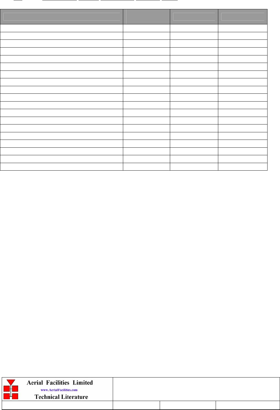
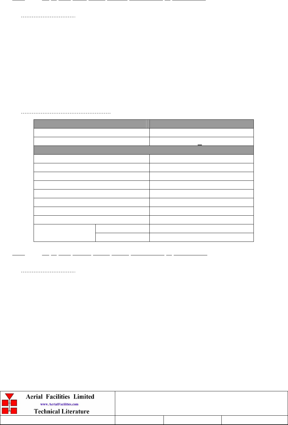
3.5 Weehawken System Frequencies Look-up Table
Agency Channel
Number Uplink Tx Downlink Rx
New Jersey Transit Bus Data System 800 CHN 1 809.2875 854.2875
New Jersey Transit Bus Data System 800 CHN 2 809.4875 854.4875
Township of North Bergen Police 800 CHN 3 810.7375 855.7375
City of Union City 800 CHN 4 821.3500 866.3500
New Jersey Transit Trunked Radio System 800 CHN 5 821.4625 866.4625
New Jersey Transit Trunked Radio System 800 CHN 6 821.4875 866.4875
New Jersey Transit Trunked Radio System 800 CHN 7 821.9625 866.9625
New Jersey Transit Trunked Radio System 800 CHN 8 821.9875 866.9875
City of Union City 800 CHN 9 822.1625 867.1625
New Jersey Transit Trunked Radio System 800 CHN 10 822.4625 867.4625
New Jersey Transit Trunked Radio System 800 CHN 11 822.4875 867.4875
New Jersey Transit Trunked Radio System 800 CHN 12 822.9625 867.9625
New Jersey Transit Trunked Radio System 800 CHN 13 822.9875 867.9875
City of Union City 800 CHN 14 823.1875 868.1875
City of Union City 800 CHN 15 823.2125 868.2125
New Jersey Transit Trunked Radio System 800 CHN 16 823.4625 868.4625
New Jersey Transit Trunked Radio System 800 CHN 17 823.4875 868.4875
New Jersey Transit Paging 900 CHN 1 929.5875
New Jersey Transit Paging 900 CHN 2 929.6125
Weehawken Tunnel 800MHz Repeater
User/Maintenance Handbook
Handbook N.-Weehawken_800 Issue No:-A
Date:-05/08/05 Page:-18 of 51
4. 800MHZ CELL ENHANCER (50-118401)
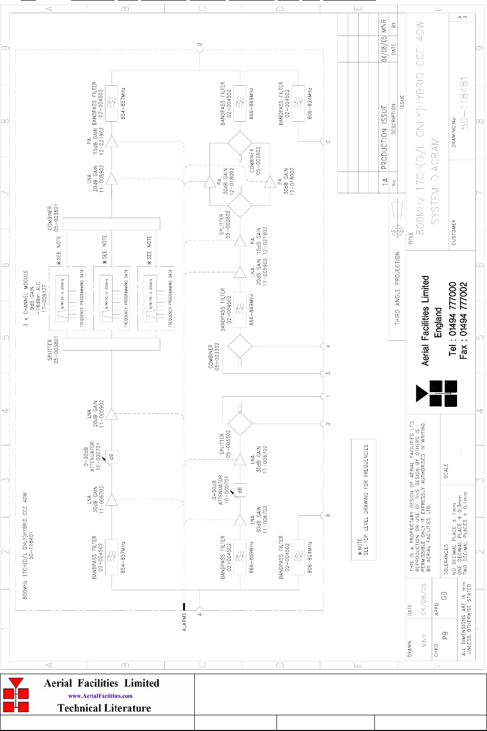
4.1 800MHz Cell Enhancer Description
The 800MHz system has 17 channels (channel selective) split into two groups of channels,
(three and fourteen) in the downlink direction and a selected band covering the whole band
in the uplink path. The system diagram shows the three channel portion of the cell enhancer
(NJ Bus Data x 2 & Town of N. Bergen Police) which covers the 854-857MHz band.
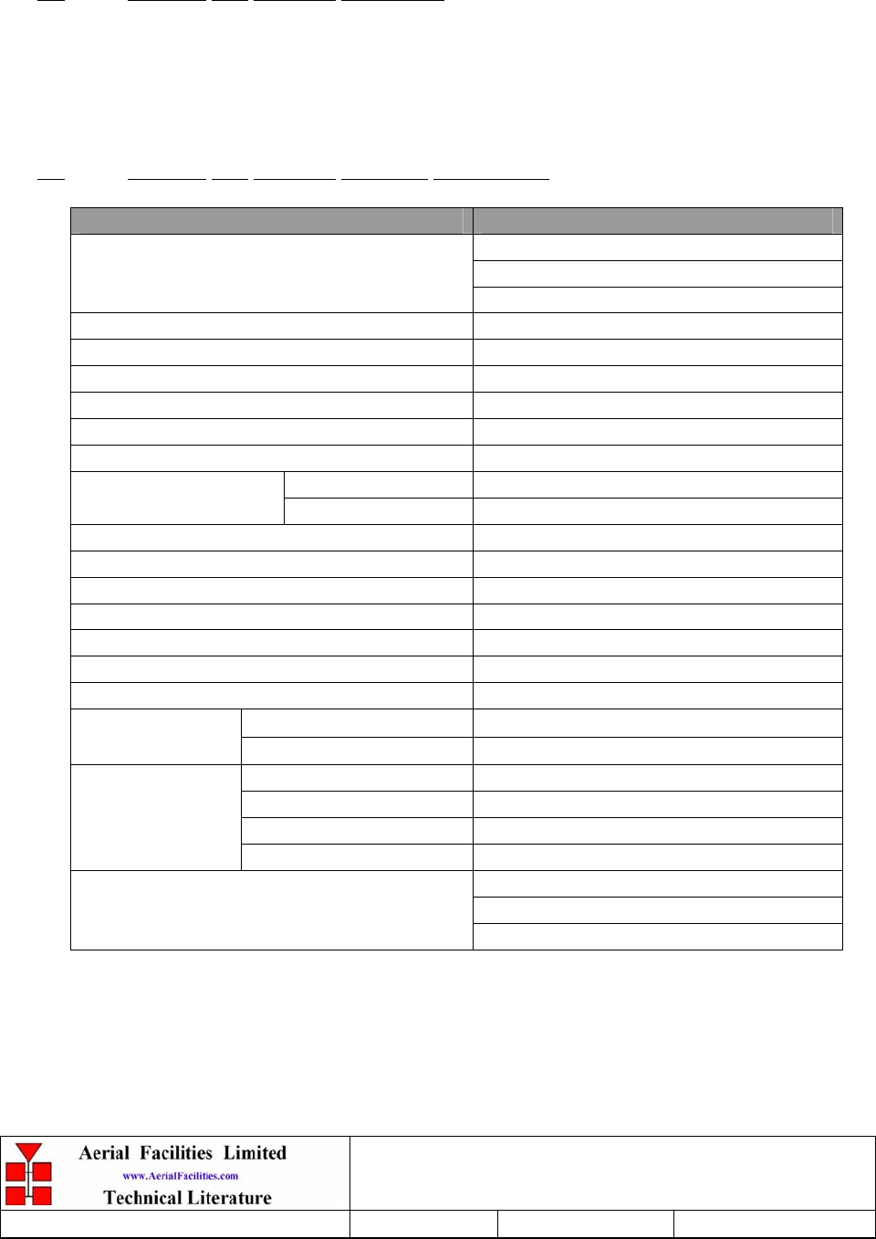
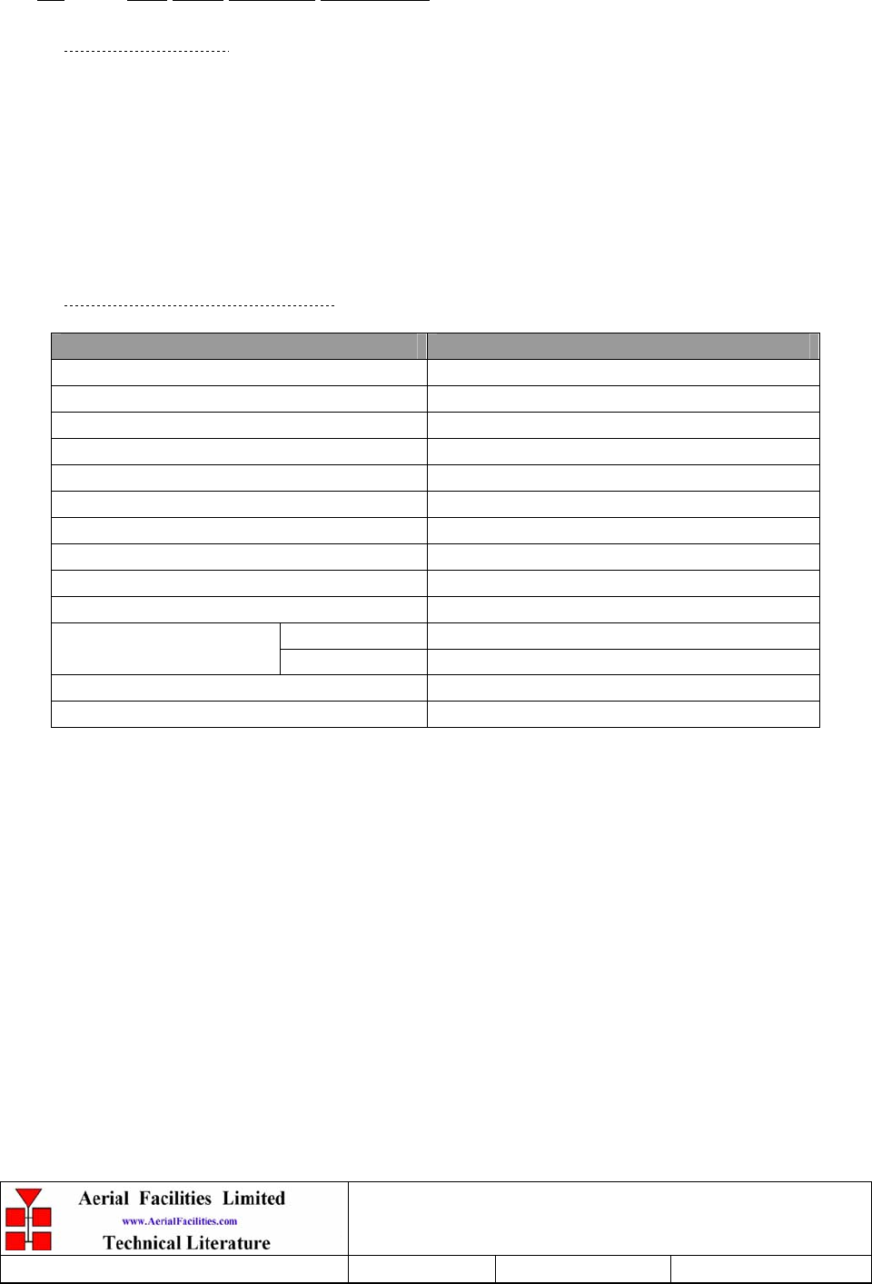
4.2 800MHz Cell Enhancer Technical Specification
PARAMETER SPECIFICATION
854-857MHz (downlink)
866-869MHz (downlink)
Frequency ranges:
806-824 (uplink)
Gain: >90dB
Gain Adjustment: 0 - 30dB (in 2dB steps)
Uplink Power: >1.0Watts
Maximum uplink output: +30.8dBm
Downlink Power: >5.0Watts
Maximum downlink output power: +37.5dBm
Uplink +44dBm
IP3: Downlink +50dBm
Downlink Ch. module AGC level: -17dBm
Uplink Ch. module AGC level: -8dBm
Noise Figure: <6dB (at maximum gain)
AGC: Fitted in channel modules
VSWR: better than 1.5:1
RF Connectors: N type, female
Shelf size: 8U
operational: -10°C to +55°C
Temperature
range: storage: -40°C to +70°C
Case: Alocrom 1200
Heatsinks: Matt black
Handles: Silver anodised alloy
Finish:
Fascia: Painted to RAL 7035
1 Downlink amplifiers
2 Uplink amplifiers
Alarms Fitted:
(volt-free contacts/TTL) 3 Each channel module
Weehawken Tunnel 800MHz Repeater
User/Maintenance Handbook
Handbook N.-Weehawken_800 Issue No:-A
Date:-05/08/05 Page:-19 of 51
4.3 800MHz Cell Enhancer System Diagram, Drg. N. 50-118481
Weehawken Tunnel 800MHz Repeater
User/Maintenance Handbook
Handbook N.-Weehawken_800 Issue No:-A
Date:-05/08/05 Page:-20 of 51
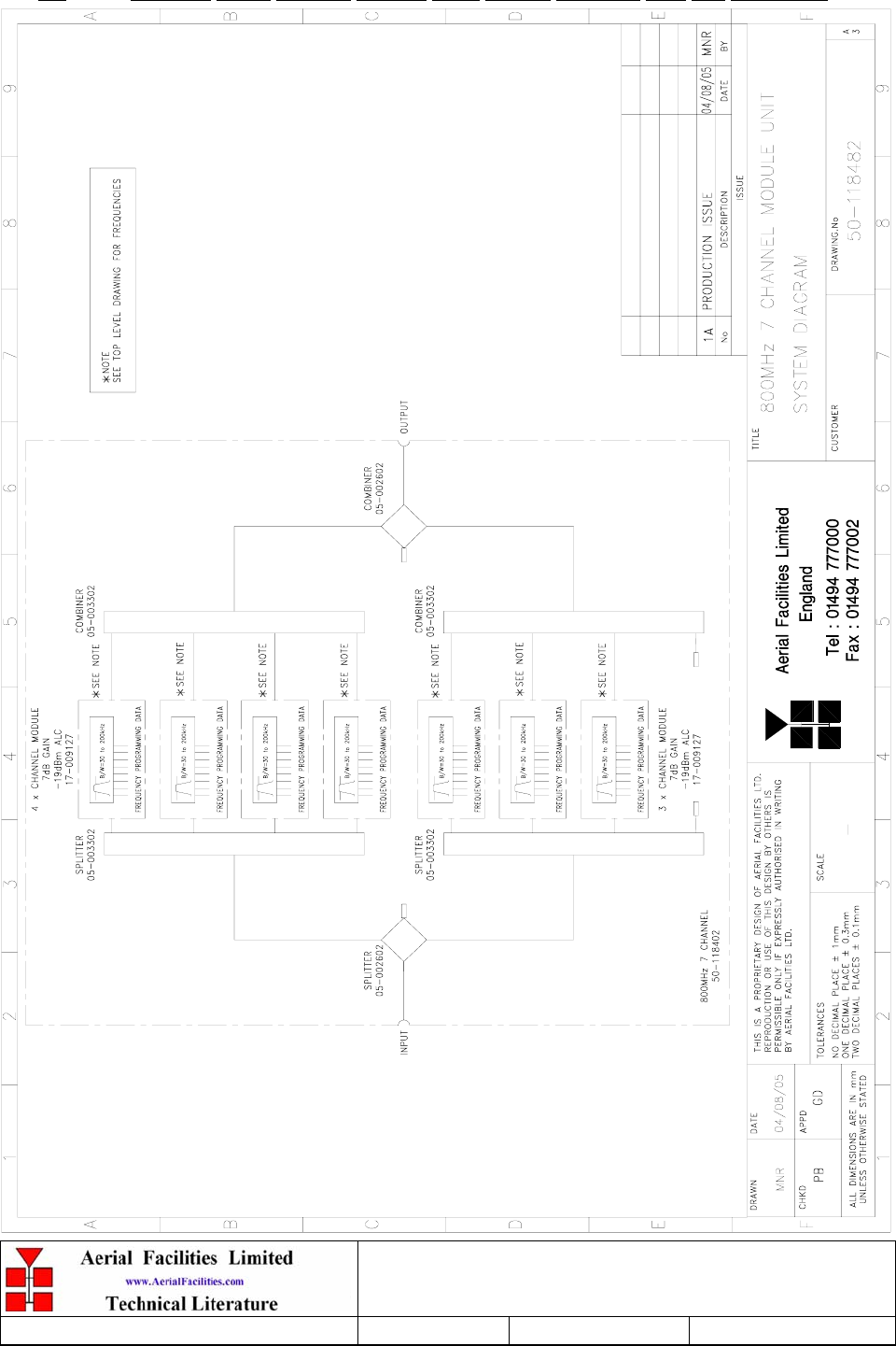
4.4 800MHz Seven Channel Module Shelf System Diagram, Drg. N. 50-118482
Weehawken Tunnel 800MHz Repeater
User/Maintenance Handbook
Handbook N.-Weehawken_800 Issue No:-A
Date:-05/08/05 Page:-21 of 51
4.5 800MHz Cell Enhancer Uplink Path, Drg. N. 50-118483

Weehawken Tunnel 800MHz Repeater
User/Maintenance Handbook
Handbook N.-Weehawken_800 Issue No:-A
Date:-05/08/05 Page:-22 of 51
4.6 800MHz Cell Enhancer Parts List
AFL Part Nō. Part Description Qty.
02-004502 4P C/L SD FILTER 920MHz (3MHz B/W) SMA 5
02-007206 900MHz 8 POLE 15-25MHz B/W "SMA" 2
05-002602 900MHz SPLITTER/COMBINER, 20W 4
05-003801 3WAY GEN.SPLIT 900MHz GEN.ASS 2
10-000701 1/4W0-30dB SWITCHED ATTENUATOR 2
11-005902 900MHz LOW NOISE AMP WITH RELAY ASS 3
11-006702 GA 800-1000MHz LNA 29dB 3
12-018002 PA 800-960MHz 20W CLASS A 2
12-021901 POWER AMPLIFIER 900MHz 1W +12V 1
12-021902 POWER AMPLIFIER 900MHz 2W +12V 1
14-000225 CASE RAIL LONG R.S.A./R.F.A. 4
17-002101 CHANNEL CONTROL MODULE 1
17-002103 26WAY RIBBON CABLE LEAD 3
17-009127 CHAN MOD 810-860MHz 30KHz 8p TCXO 3
20-001601 12V RELAY BOARD 1
50-012825 CCE RACK MOUNTED HEATSINK BRACKET 4
50-012843 CCE RACK 8U CHASSIS 400mm DEEP 1
50-012844 CCE RACK LID 400mm DEEP 1
50-027720 RACK MTD CHAN C.E. MODIFIED HEATSINK 2
80-008901 12V RELAY PCB ASSEMBLY 1
80-090822 C/E 8U FRONT PANEL, AFL (RAL7035) 1
91-030002 N ADAPTOR PANEL FEMALE:FEMALE 4
91-130005 SMA BULKHEAD ADAPTOR F/F 4
91-500001 POWER PLG 3 PIN PNL.MOUNT NC-X 1
91-510003 3 PIN R.ANGLE FREE SOC.NC-X. 1
91-510032 20A SOCKET CONTACT PIN 4
91-600007 'D' 9 WAY BLACK SHELL 8
91-600014 'D' 9 WAY SOCKET S/B (NON FILTERED) 8
91-600015 'D' 9 WAY PLUG S/B (NON FILTERED) 1
91-660001 2W5 MIXED D TYPE SOCKET (7 WAY) 2
96-700034 LED RED 5mm IP67 1
96-700035 LED GREEN 5mm IP67 1
96-920043 20A CIRCUIT BREAKER (ETA 2-5700) 1
97-400005 HANDLE TYPE H6802 3U [ALLOY] 2
99-200008 DANGER HIGH VOLTAGE LABEL 2 x 2' 1
99-200017 CAUTION HEAVY LABEL 75 x 55mm 2
Weehawken Tunnel 800MHz Repeater
User/Maintenance Handbook
Handbook N.-Weehawken_800 Issue No:-A
Date:-05/08/05 Page:-23 of 51
5. POWER SUPPLY & ALARMS
5.1 800MHz Power Supply (80-231302)
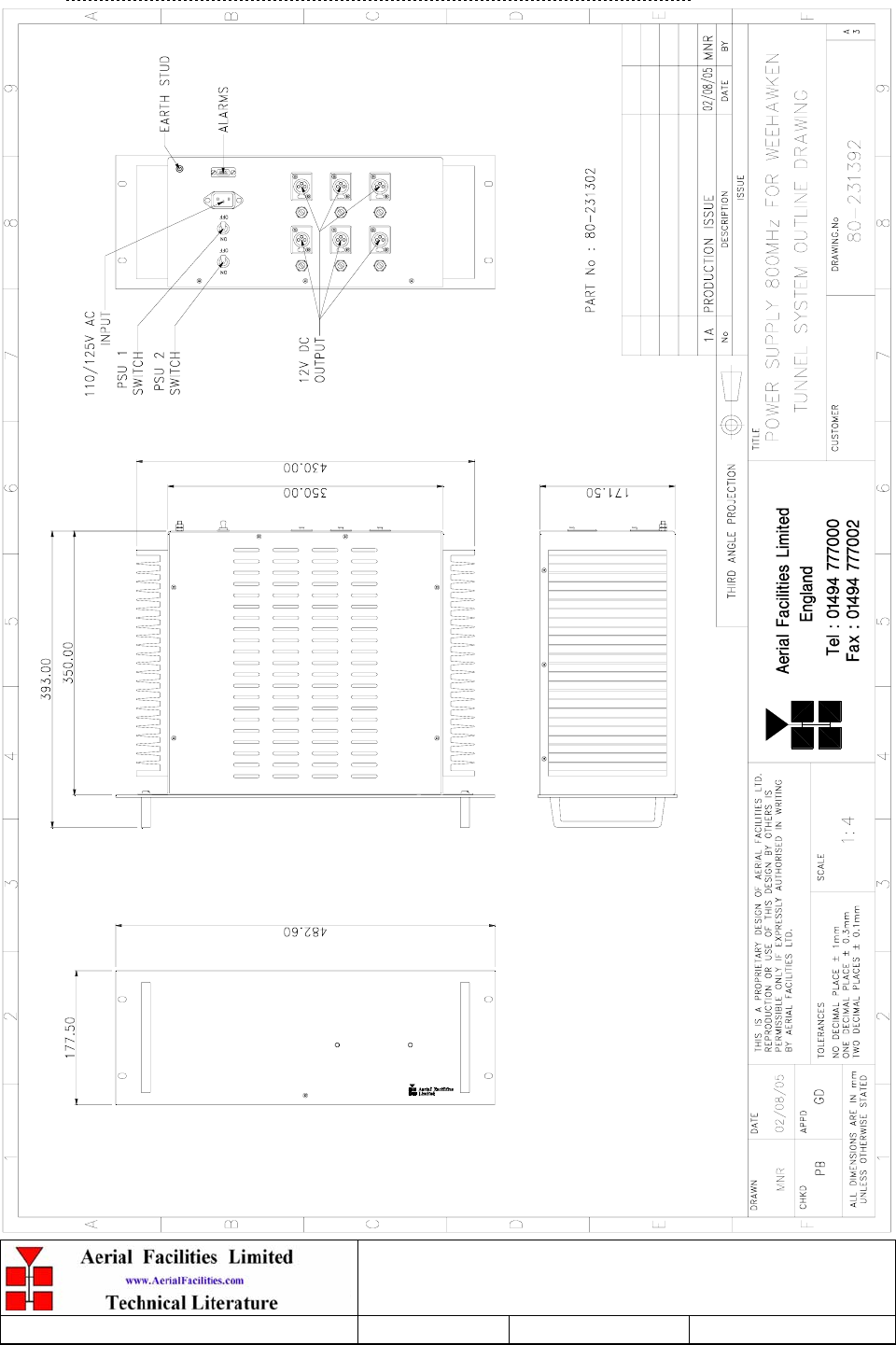
5.1.1 800MHz Power Supply Description
The power supply for the 800MHz cell enhancer uses 15V PSU modules ‘turned down’ to
12V (all the amplifiers in the 800MHz CE use 12V DC supply). It is a standard power
supply shelf using two PSU modules with their outputs combined through power diodes and
terminating in six, dedicated 12V outputs. Failure of either PSU module will trigger a non-
latching summary alarm, (short-term mains failures will allow the system to return to a ‘non-
alarmed’ state). The alarm interface is on the alarm ‘D’ connector pins 1 & 2.
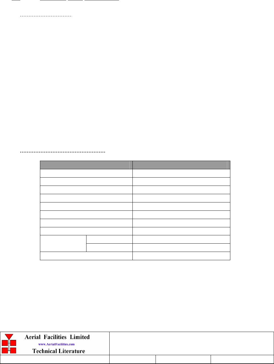
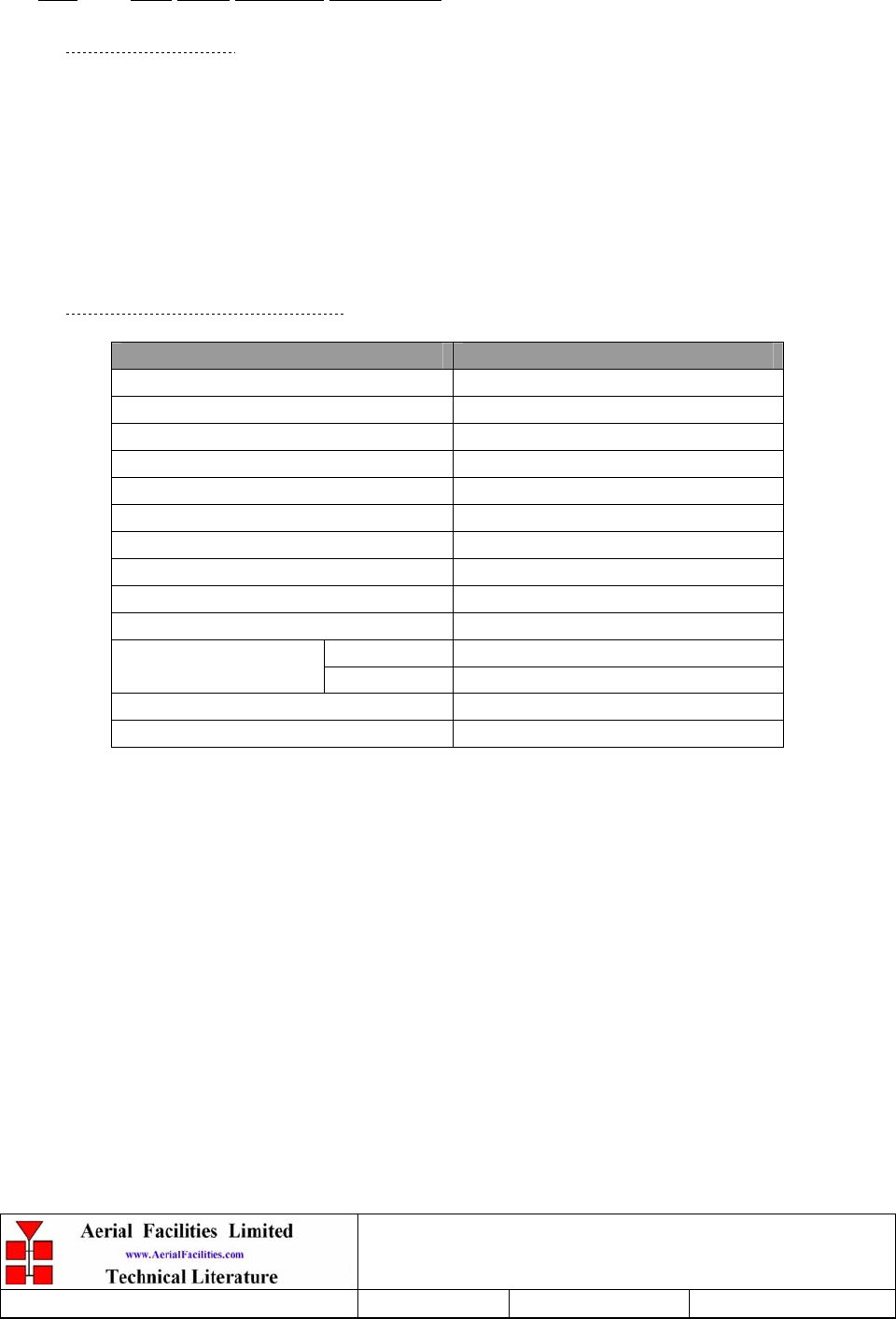
5.1.2 800MHz Power Supply Technical Specification
PARAMETER SPECIFICATION
Input: 110V AC @50/60Hz (single port)
Outputs: 6 x 12V DC @ 20A each
Front panel indicators: (x 2) Green LED for ‘PSU1/PSU2 ON’’
Fuses 1 x 20A each outlet socket
DC Socket XLR
operational: -10°C to +55°C
Temperature range storage: -40ºC to +70ºC
Alarmed devices: Either PSU failure
Alarm interface (volt-free contacts): ‘D’ type alarm connector, pins 1 & 2
MTBF: >50,000 hours
Earthing: M8 stud
5.1.3 800MHz Power Supply System Diagram
The system diagram is not available at the time of writing this document.
Weehawken Tunnel 800MHz Repeater
User/Maintenance Handbook
Handbook N.-Weehawken_800 Issue No:-A
Date:-05/08/05 Page:-24 of 51
5.1.4 800MHz Power Supply Outline Drawing, Drg. N. 80-231392

Weehawken Tunnel 800MHz Repeater
User/Maintenance Handbook
Handbook N.-Weehawken_800 Issue No:-A
Date:-05/08/05 Page:-25 of 51
5.1.5 800MHz Power Supply Parts List
AFL Part Nō. Part Description Qty.
13-003301 MAINS FILTER 8AMP ASSEMBLY 1
20-001601 12V RELAY BOARD 1
80-008920 DUAL PSU HEATSINK 2
80-008921 DUAL PSU CASE 1
80-008922 DUAL PSU LID 1
80-008925 DUAL PSU FRONT PANEL 1
80-020632 2U CHASSIS LID FIXING RAIL 4
91-500025 3 PIN RIGHT ANGLE FREE PLUG NC-X 6
91-510004 3 PIN PNL.MOUNT SOCKET NC-X 6
91-510035 3 WAY MATE N LOK PLUG HOUSING 2
91-520001 PWR MAINS INL FIXED/SOLD.TERMS 1
91-520005 MAINS LEAD 1
91-520010 MAINS RETAINING CLIP 1
91-520032 MATE N LOK SOCKET CONTACT 20/14 AWG 6
91-600015 'D' 9 WAY PLUG S/B (NON FILTERED) 1
91-800014 3 WAY TERMINAL BLOCK 1
91-800015 TRIPLE DECK TERMINAL BLOCK 8
91-800016 TRIPLE DECK TERMINAL JUMPER 6
91-800017 TRIPLE DECK TERMINAL END 1
91-800028 DIN RAIL END-STOP 2
91-800031 SYMETRIC 35 x 7.5mm DIN RAIL 0
92-900014 DIN RAIL (TOP HAT) EARTH CLAMP M5 1
93-510077 0R02 50W RESISTOR ALUMINIUM CLAD 2
94-100004 STPS12045TV 60A DUAL DIODE 1
95-100007 TX.FERRITE ISOL.HT.SINK B/ANOD 3
96-110034 FUSE HOLDER 16-30A, 32mm BODY ONLY 4
96-110064 FUSE HOLDER 16-30A, 32mm INSERT 4
96-300057 15V 27A PSU 400W (XP BCC) 2
96-600001 INSULATING BOOT LARGE 1
96-700034 LED RED 5mm IP67 1
96-700035 LED GREEN 5mm IP67 2
96-920023 5A CIRCUIT BREAKER (ETA) 2
97-400002 HANDLE TYPE H6803 4U.[ALLOY] 2
Weehawken Tunnel 800MHz Repeater
User/Maintenance Handbook
Handbook N.-Weehawken_800 Issue No:-A
Date:-05/08/05 Page:-26 of 51
5.2 Alarm/Monitor Shelf (80-231303)
5.2.1 Alarm/Monitor Shelf Description
The alarm shelf acts as an alarm concentrator for all the alarms in the system. Firstly, within
each shelf containing active components, the individually alarmed modules are ‘summed’
and presented to that shelves’ 9-way alarm connector as a volt-free relay contact pair. These
alarm contact pairs are wired to the krone block in the lower rack space and from there the
pairs are presented to the alarm shelf. At the alarm shelf the pairs are summed together to
form an overall system alarm. In this way a system alarm may be broken down to scrutinise
the shelf alarm and ultimately to the individual modules’ alarms.
This shelf has its own dedicated mains-driven power 12V DC supply.
As all the alarms in the system are ‘held closed loops’, should any power supply fail, the
main system alarm will be triggered.
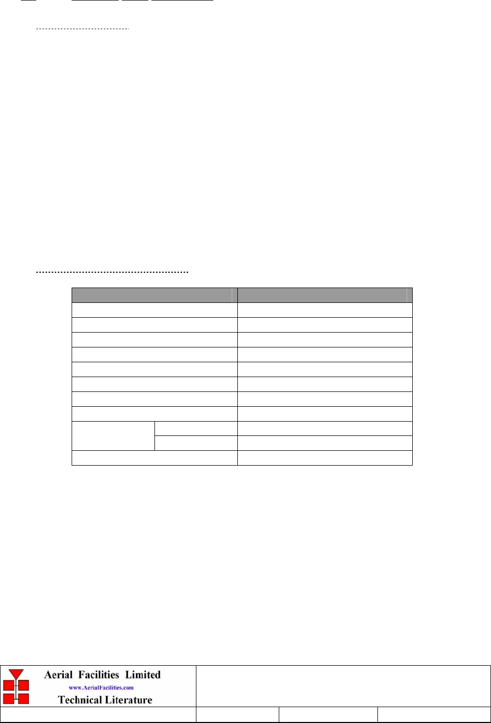
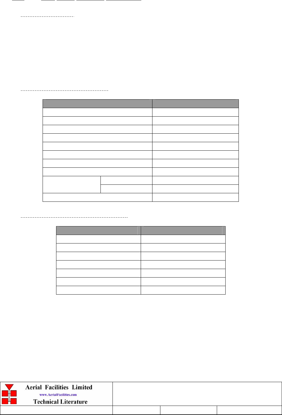
5.2.2 Alarm/Monitor Shelf Technical Specification
PARAMETER SPECIFICATION
Operating voltage: 12V (floating earth)
Alarm output relay contacts:
Max. switch current: 1.0Amp
Max. switch volts: 120Vdc/60VA
Max. switch power: 24W/60VA
Min. switch load: 10.0µA/10.0mV
Relay isolation: 1.5kV
Mechanical life: >2x10⁷ operations
Relay approval: BT type 56
Connector details: 25 Way ‘D’ Connector
operational: :-10°C to +55°C
Temperature range storage: :-40°C to +70°C
Weehawken Tunnel 800MHz Repeater
User/Maintenance Handbook
Handbook N.-Weehawken_800 Issue No:-A
Date:-05/08/05 Page:-27 of 51
5.2.3 Alarm/Monitor Shelf Parts List
AFL Part Nō. Part Description Qty.
19-000724 1U 19" UNIT FRONT PANEL FAB 1
19-000725 1U 19" UNIT 400 DEEP CHASSIS + BKT 1
19-000826 2U,3U,4U 19" UNIT 400 DEEP LID 1
20-001601 12V RELAY BOARD 4
91-520003 POWER SWITCHD/FUSED MAINS INL. 1
91-520005 MAINS LEAD 1
91-520010 MAINS RETAINING CLIP 1
91-600014 'D' 9 WAY SOCKET S/B (NON FILTERED) 8
91-600015 'D' 9 WAY PLUG S/B (NON FILTERED) 8
96-300072 12V POWER SUPPLY TML15112C 1
96-600001 INSULATING BOOT LARGE 1
96-700034 LED RED 5mm IP67 8
96-700035 LED GREEN 5mm IP67 1
Weehawken Tunnel 800MHz Repeater
User/Maintenance Handbook
Handbook N.-Weehawken_800 Issue No:-A
Date:-05/08/05 Page:-28 of 51
6. SUB-UNIT MODULES
Note that the sub unit modules are tabled in part number order – the modules pertinent to any
particular shelf will be found in the parts list under the heading of that shelf.
6.1 Bandpass Filter (02-004502)
6.1.1 Description
The bandpass filters are multi-section designs with a bandwidth dependent upon the passband
frequencies, (both tuned to customer requirements). The response shape is basically Chebyshev
with a passband design ripple of 0.1dB. The filters are of slot coupled, folded combline design,
and are carefully aligned during manufacture in order to optimise the insertion loss, VSWR and
intermodulation characteristics of the unit. The tuned elements are silver-plated to reduce
surface ohmic losses and maintain a good VSWR figure and 50 load at the input and output
ports.
Being passive devices, the bandpass filters should have an extremely long operational life and
require no maintenance. Should a filter be suspect, it is usually most time efficient to replace
the module rather than attempt repair or re-tuning.
No adjustments should be attempted without full network sweep analysis facilities to monitor
both insertion loss and VSWR simultaneously.
6.1.2 Technical Specification
PARAMETER SPECIFICATION
Response Type Chebyshev
Frequency Range: 751-862MHz (tuned to spec.)
Bandwidth: 12MHz (tuned to spec.)
Number of Sections: 5
Insertion Loss: 1.2 dB
VSWR: better than 1.2:1
Connectors: SMA female
Power Handling: 100W max
operation: -10°C to +60°C Temperature
range: storage: -20°C to +70°C
Weight: 3 kg (typical)
Weehawken Tunnel 800MHz Repeater
User/Maintenance Handbook
Handbook N.-Weehawken_800 Issue No:-A
Date:-05/08/05 Page:-29 of 51
6.2 Bandpass Filter (02-007206)
6.2.1 Description
The bandpass filters are multi-section designs with a bandwidth dependent upon the passband
frequencies, (both tuned to customer requirements). The response shape is basically Chebyshev
with a passband design ripple of 0.1dB. The filters are of slot coupled, folded combline design,
and are carefully aligned during manufacture in order to optimise the insertion loss, VSWR and
intermodulation characteristics of the unit. The tuned elements are silver-plated to reduce
surface ohmic losses and maintain a good VSWR figure and 50 load at the input and output
ports.
Being passive devices, the bandpass filters should have an extremely long operational life and
require no maintenance. Should a filter be suspect, it is usually most time efficient to replace
the module rather than attempt repair or re-tuning.
No adjustments should be attempted without full network sweep analysis facilities to monitor
both insertion loss and VSWR simultaneously.
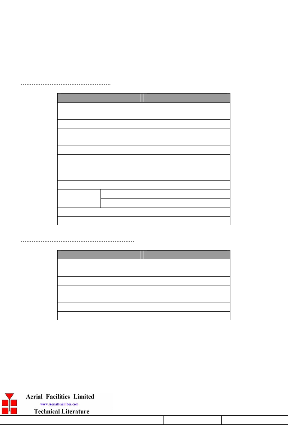
6.2.2 Technical Specification
PARAMETER SPECIFICATION
Response Type Chebyshev
Frequency range: 800 - 950MHz (tuned to spec.)
Bandwidth: 25MHz (tuned to spec.)
Number of sections: 8
Insertion Loss: 1.2 dB
VSWR: better than 1.2:1
Connectors: SMA female
Power Handling: 100W max
operation: -10°C to +60°C Temperature
range: storage: -20°C to +70°C
Weight: 3 kg (typical)
Weehawken Tunnel 800MHz Repeater
User/Maintenance Handbook
Handbook N.-Weehawken_800 Issue No:-A
Date:-05/08/05 Page:-30 of 51
6.7 900MHz Splitter/Combiner (05-002602)
6.7.1 Description
The Splitter/Combiner used is a device for accurately matching two or more RF signals to
single or multiple ports, whilst maintaining an accurate 50Ω load to all inputs/outputs and
ensuring that the VSWR and insertion losses are kept to a minimum. Any unused ports will be
terminated with an appropriate 50Ω load.
Being passive devices, the splitters should have an extremely long operational life and require
no maintenance. Should a unit be suspect, it is usually most time efficient to replace the whole
module rather than attempt repair or re-tuning.
Being passive devices, the splitters should have an extremely long operational life and require
no maintenance. Should a unit be suspect, it is usually most time efficient to replace the whole
module rather than attempt repair or re-tuning.
6.7.2 Technical Specification
PARAMETER SPECIFICATION
Narrowband: 815 – 960MHz
Frequency range: Broadband: 800 – 1200MHz
Narrowband: 145MHz
Bandwidth: Broadband: 400MHz
Input ports: 1
Output ports: 2
Narrowband: 3.3dB
Insertion loss: Broadband: 3.5dB
Return loss input & output: 1.3:1
Impedance: 50
Narrowband: >20dB
Isolation: Broadband: >18dB
MTFB: >180,000 hours
Splitting: 20Watts
Power rating: Combining: 0.5Watt
Connectors: SMA female
Weight: 200g (approximately)
Size: 54 x 44 x 21mm (including
connectors)

Weehawken Tunnel 800MHz Repeater
User/Maintenance Handbook
Handbook N.-Weehawken_800 Issue No:-A
Date:-05/08/05 Page:-31 of 51
6.8 ¼Watt 0- -30 & 0-15dB Switched Attenuator (10-000701 & 10-000901)
6.8.1 General Application
In many practical applications for Cell Enhancers etc., the gain in each path is found to be
excessive. Therefore, provision is made within the unit for the setting of attenuation in each
path, to reduce the gain.
6.8.2 Switched Attenuators
The AFL switched attenuators are available in two different types; 0 – 30dB in 2 dB steps, or 0
– 15dB in 1 dB steps. The attenuation is simply set using the four miniature toggle switches on
the top of each unit. Each switch is clearly marked with the attenuation it provides, and the total
attenuation in line is the sum of the values switched in. They are designed to maintain an
accurate 50 impedance over their operating frequency at both input and output.
Weehawken Tunnel 800MHz Repeater
User/Maintenance Handbook
Handbook N.-Weehawken_800 Issue No:-A
Date:-05/08/05 Page:-32 of 51
6.9 Low Noise Amplifier (11-005902)
6.9.1 Description
The Gallium-Arsenide low noise amplifier used in the unit is a double stage, solid-state low
noise amplifier. Class A circuitry is used throughout the units to ensure excellent linearity and
extremely low noise over a very wide dynamic range. The active devices are very moderately
rated to provide a long trouble-free working life. There are no adjustments on these amplifiers,
and in the unlikely event of a failure, then the complete amplifier should be replaced. This
amplifier features its own in-built alarm system which gives a volt-free relay contact type alarm
that is easily integrated into the main alarm system.
6.9.2 Technical Specification
PARAMETER SPECIFICATION
Frequency range: 800 – 960MHz
Bandwidth: <170MHz
Gain: 19.5dB (typical)
1dB Compression point: 21dBm
OIP3: 33dBm
Input/Output Return Loss: >20dB
Noise Figure: 1dB (typical)
Power consumption: 190mA @ 24V DC
Supply voltage: 10-24V DC
Connectors: SMA female
operational: -10°C to +60°C
Temperature range: storage: -20°C to +70°C
Size: 90 x 55 x 30.2mm
Weight: 0.28kg
Weehawken Tunnel 800MHz Repeater
User/Maintenance Handbook
Handbook N.-Weehawken_800 Issue No:-A
Date:-05/08/05 Page:-33 of 51
6.10 Low Noise Amplifier (11-006702)
6.10.1 Description
The Gallium-Arsenide low noise amplifiers used in the system are double stage, solid-state
low noise amplifiers. Class A circuitry is used throughout the units to ensure excellent
linearity and extremely low noise over a very wide dynamic range. The active devices are
very moderately rated to provide a long trouble-free working life. There are no adjustments
on these amplifiers, and in the unlikely event of a failure, then the complete amplifier should
be replaced. This amplifier features its own in-built alarm system which gives a volt-free
relay contact type alarm that is easily integrated into the main alarm system.
6.10.2 Technical Specification
PARAMETER SPECIFICATION
Frequency range: 800 – 1000MHz
Bandwidth: <200MHz
Gain: 29dB (typical)
1dB Compression point: 20dBm
OIP3: 33dBm
Input/Output return loss: >18dB
Noise figure: 1.3dB (typical)
Power consumption: 180mA @ 24V DC
Supply voltage: 10-24V DC
Connectors: SMA female
operational: -10°C to +60°C
Temperature range: storage: -20°C to +70°C
Size: 90 x 55 x 30.2mm
Weight: 290gms (approximately)
Weehawken Tunnel 800MHz Repeater
User/Maintenance Handbook
Handbook N.-Weehawken_800 Issue No:-A
Date:-05/08/05 Page:-34 of 51
6.11 20W Power Amplifier (12-018002)
6.11.1 Description
This amplifier is a Class A 20W power amplifier from 800-960MHz in a 1 stage balanced
configuration. It demonstrates a very high linearity and a very good input/output return loss
(RL). It has built in a Current Fault Alarm Function.
Its housing is an aluminium case (Alocrom 1200 finish) with SMA connectors for the RF
input/output and a D-Type connector for the power supply and the Current Fault Alarm
Function.
6.11.2 Technical Specification
PARAMETER SPECIFICATION
Frequency range: 800-960MHz
Small signal gain: 30dB
Gain flatness: ±1.2dB
I/O Return loss: >18dB
1dB compression point: 42.8dBm
OIP3: 56dBm
Supply voltage: 24V DC
Supply current: 5.0Amps (Typical)
operational: -10°C to +60°C Temperature
range storage: -20°C to +70°C
Weight: <2kg (no heatsink)
6.11.3 PA 7-Way Connector Pin-outs
Connector Pin Signal
A1 (large pin) +24V DC
A2 (large pin) GND
1 Alarm relay common
2 TTL alarm/0V good
3 Alarm relay contact (bad)
4 Alarm relay contact (good)
5 O/C good/0V bad (TTL)
Weehawken Tunnel 800MHz Repeater
User/Maintenance Handbook
Handbook N.-Weehawken_800 Issue No:-A
Date:-05/08/05 Page:-35 of 51
6.12 800MHz 1Watt Low Power Amplifier (12-021901)
6.12.1 Description
The low power amplifier used is a triple stage solid-state low-noise amplifier. Class A circuitry
is used in the unit to ensure excellent linearity over a very wide dynamic range. The three active
devices are very moderately rated to provide a long trouble-free working life. There are no
adjustments on this amplifier, and in the unlikely event of failure then the entire amplifier
should be replaced.
6.12.2 Technical Specification
PARAMETER SPECIFICATION
Frequency range: 800-960MHz
Bandwidth: 20MHz (tuned to spec.)
Maximum RF output: >1.0 Watt
Gain: 15dB
1dB compression point: +30.5dBm
3rd order intercept point: +43dBm
Noise Figure: <6dB
VSWR: better than 1.5:1
Connectors: SMA female
Supply: 500mA @ 10-15V DC
operational: -10°C to +60°C
Temperature
range: storage: -20°C to +70°C
Weight: 0.5 kg
Size: 167x52x25mm
6.12.3 LPA 7-Way Connector Pin-outs
Connector Pin Signal
A1 (large pin) +24V DC
A2 (large pin) GND
1 Alarm relay common
2 TTL alarm/0V good
3 Alarm relay contact (bad)
4 Alarm relay contact (good)
5 O/C good/0V bad (TTL)

Weehawken Tunnel 800MHz Repeater
User/Maintenance Handbook
Handbook N.-Weehawken_800 Issue No:-A
Date:-05/08/05 Page:-36 of 51
6.13 D.I.P Channel Control Module (17-002101)
6.13.1 Description
The operating frequency for each channel in each repeater is programmed by 16 DIL (Dual
In Line) switches. The programming switches are mounted in the Channel Control Module.
The Channel Selectivity Modules are connected to the Channel Control Module via multi-
way ribbon cables.
Adjacent to the DIL switches for each channel is a toggle switch to turn on and off individual
channels as required. A green LED indicates the power status of each channel.
A red LED shows the alarm condition for each channel. An illuminated alarm LED indicates
that the synthesiser has not achieved phase lock and that the module is disabled. There is a
problem which requires investigation, often a frequency programmed outside the operating
frequency range.
The following information is necessary before attempting the programming procedure.
1) operating frequency
2) synthesiser channel spacing (step size)
3) synthesiser offset (IF)
Weehawken Tunnel 800MHz Repeater
User/Maintenance Handbook
Handbook N.-Weehawken_800 Issue No:-A
Date:-05/08/05 Page:-37 of 51
6.13.2 Programming Procedure
Check that the required frequency falls within the operational frequency limits of the Cell
Enhancer.
For each channel required, subtract the synthesiser offset from the required operating
frequency and record the resulting local oscillator frequency.
Divide each local oscillator frequency by the channel spacing and check that the result is an
integer (i.e: no remainder).
If the synthesiser division ratio is not an integer value, check the required operational
frequency and repeat the calculation checking for mistakes.
Convert the required local oscillator frequency to synthesiser programming switch state
patterns according to the following table.
6.13.3 12.5kHz step size switch functions
Switch
Number
Synthesiser offset added when switch in UP
position
1 +12.5kHz
2 +25kHz
3 +50kHz
4 +100kHz
5 +200kHz
6 +400kHz
7 +800kHz
8 +1.6MHz
9 +3.2MHz
10 +6.4MHz
11 +12.8MHz
12 +25.6MHz
13 +51.2MHz
14 +102.4MHz
15 +204.8MHz
16 +409.6MHz
Weehawken Tunnel 800MHz Repeater
User/Maintenance Handbook
Handbook N.-Weehawken_800 Issue No:-A
Date:-05/08/05 Page:-38 of 51
6.13.4 25kHz step size switch functions
Switch
Number
Synthesiser offset added when switch in UP
position
1 +25kHz
2 +50kHz
3 +100kHz
4 +200kHz
5 +400kHz
6 +800kHz
7 +1.6MHz
8 +3.2MHz
9 +6.4MHz
10 +12.8MHz
11 +25.6MHz
12 +51.2MHz
13 +102.4MHz
14 +204.8MHz
15 +409.6MHz
16 +819.2MHz
6.13.5 Programming Example
Frequency required: 454.000MHz
Channel spacing: 12.5kHz
Synthesiser offset: -21.4MHz
The Local Oscillator frequency is therefore:
454.000 – 21.4 = 432.600MHz
Dividing the LO frequency by the channel spacing of 0.0125MHz:
432.600 = 34608
0.0125
This is an integer value, therefore it is OK to proceed.
Local Oscillator
Frequency
Switch settings
16 15 14 13 12 11 10 9 8 7 6 5 4 3 2 1
432.600 MHz 1 0 0 0 0 1 1 1 0 0 1 1 0 0 0 0
Switch setting: 0 = switch DOWN (ON, frequency ignored )
1 = switch UP (OFF, frequency added )

Weehawken Tunnel 800MHz Repeater
User/Maintenance Handbook
Handbook N.-Weehawken_800 Issue No:-A
Date:-05/08/05 Page:-39 of 51
6.13.6 17-002101 Controller Module DIP Switch Connector Data
IDC PIN 25-way Connector Function (12.5kHz steps)
1 13 Freq. bit 1 (12.5kHz)
2 25 Freq. bit 2 (25kHz)
3 12 Freq. bit 3 (50kHz)
4 24 Freq. bit 4 (100kHz)
5 11 Freq. bit 5 (200kHz)
6 23 Freq. bit 6 (400kHz)
7 10 Freq. bit 7 (800kHz)
8 22 Freq. bit 8 (1.6MHz)
9 9 Freq. bit 9 (3.2MHz)
10 21 Freq. bit 10 (6.4MHz)
11 8 Freq. bit 11 (12.8MHz)
12 20 Freq. bit 12 (25.6MHz)
13 7 Freq. bit 13 (51.2MHz)
14 19 Freq. bit 14 (102.4MHz)
15 6 Freq. bit 15 (204.8MHz)
16 18 Freq. bit 16 (409.6MHz)
17 5 Module alarm
18 17 Gain bit 1
19 4 Gain bit 2
20 16 Gain bit 3
21 3 Gain bit 4
22 15 +5V
23 2 0V
24 14 Switched 12V
25 1 0V
26 --- ---
Weehawken Tunnel 800MHz Repeater
User/Maintenance Handbook
Handbook N.-Weehawken_800 Issue No:-A
Date:-05/08/05 Page:-40 of 51
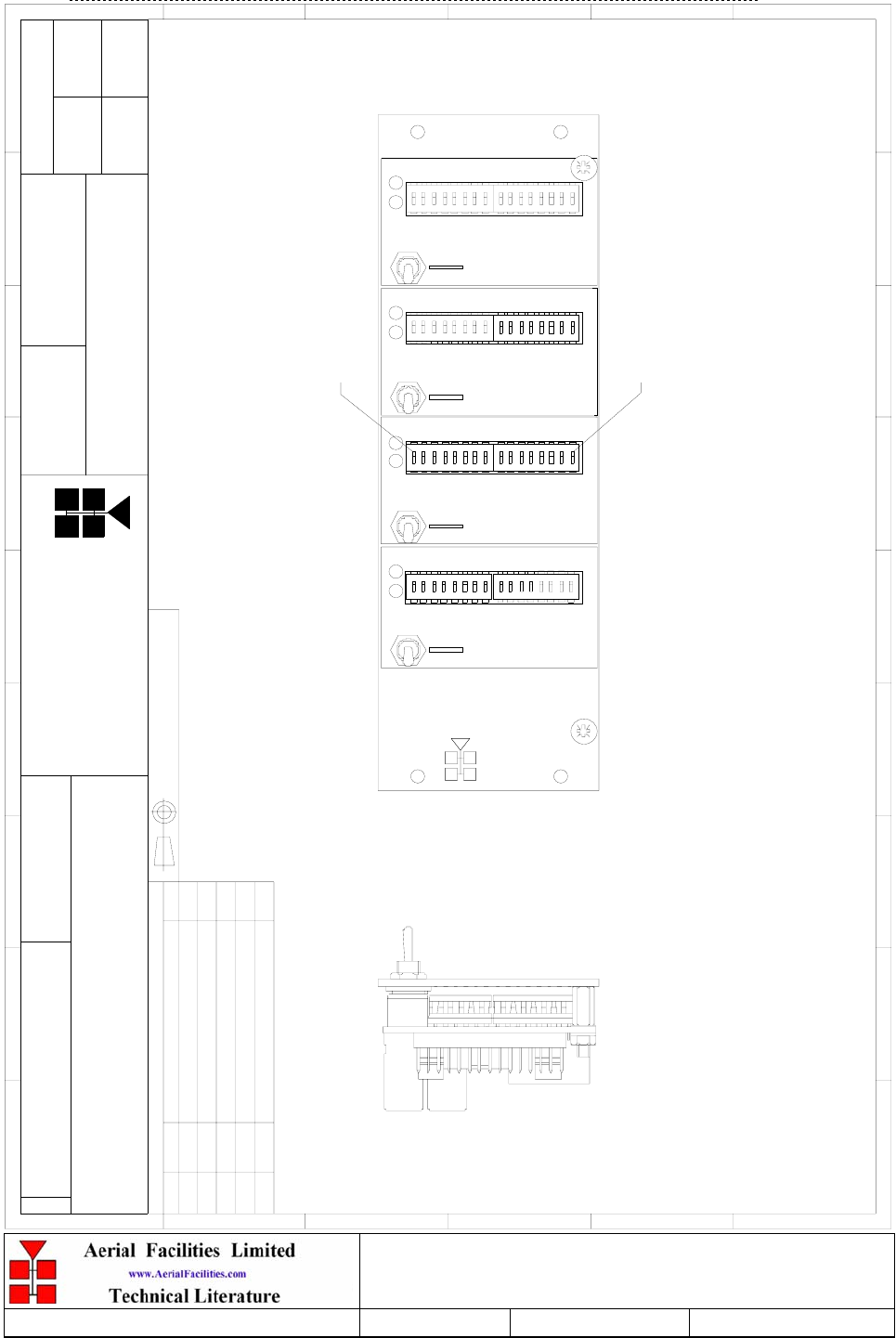
6.13.7 Drg. N. 17-002190, DIP Switch Module Controller Outline Drawing
BYDATEDESCRIPTIONNo
ISSUE
THIRD ANGL E PROJECTION
12
3456789
A
B
C
D
E
F
1 23456789
A
B
C
D
E
F
Fax : 01494 777002
Tel : 01494 777000
Aerial Facilities Limited
THIS IS A PROPRIETARY DESIGN OF AERIAL FACILITIES LTD.
REPRODUCTION OR USE OF THIS DESIGN BY OTHERS IS
PERMISSIBLE ONLY IF EXPRESSLY AUTHORISED IN WRITING
BY AERIAL FACILITIES LTD.
NO DECIMAL PLACE ± 1 mm
O NE DECIMAL PL ACE ± 0.3 mm
TWO DECIMAL PL ACES ± 0.1mm
AL L DIMENSIO NS ARE IN mm
UNLESS OTHERWISE STATED
CHKD
DRAWN
APPD
DATE
T O L ERANCES SCALE
England
CUSTO MER DRAWING.No
TITLE
3
A
CHANNELISED CELL ENHANCER,CHANNEL
CONTROL MODULE,OUTLINE
17-002190
NTS
DJL 11/11/94
CHANNEL 4
PROGRAM
PROGRAM
CHANNEL 2
CHANNEL 1
PROGRAM
CHANNEL 3
PROGRAM
OFF
PO W ER
AL AR M
78
ON
PO W ER
AL AR M
OFF
ON
PO W ER
ON
OFF
AL AR M
PO W ER
OFF
ON
AL AR M
ON.
654312
Limited
MODULE
CHANNEL CONTROL
Aerial Facilities
FINISH : ALOCROM 1200
MATERIAL : FRONT PANEL-ALUMINIUM ALLOY
BM JD
DJL
11/11/94
PRODUCTION ISSUE(CR0629)
1
2
2A PRODUCTION ISSUE (CR0962)
CR0779
10/4/96
DJL
SEW
25/1/99
ON.
87563421
16 1
8
ON.
7654321
ON.
87563421
16 1
8
ON.
7654321
ON.
87563421
16 1
8
ON.
7654321
ON.
87563421
16 1
SWITCH 1
SWITCH 16
3A
1/10/02
DJL
ECN2646

Weehawken Tunnel 800MHz Repeater
User/Maintenance Handbook
Handbook N.-Weehawken_800 Issue No:-A
Date:-05/08/05 Page:-41 of 51
6.14 Channel Selective Modules (17-003033, 17-009143, 17-009127 & 17-010803)
6.14.1 Description
The channel selectivity module is employed when the Cell Enhancer requirement dictates that
very narrow bandwidths (single operating channels), must be selected from within the operating
passband. One channel selectivity module is required for each channel.
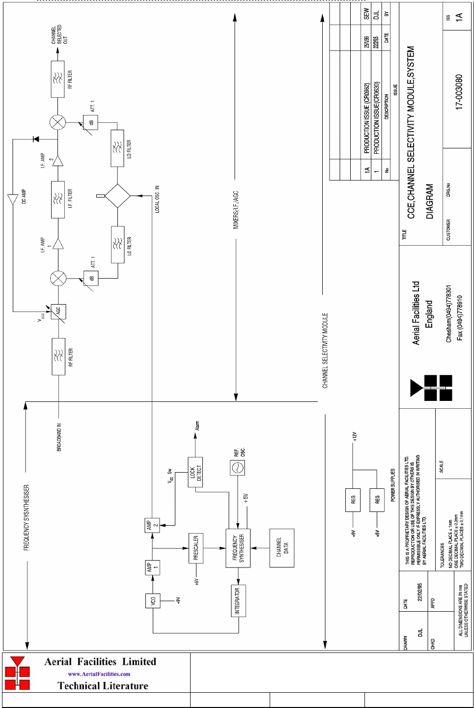
The Channel Selectivity Module is an Up/Down frequency converter that mixes the incoming
channel frequency with a synthesised local oscillator, so that it is down-converted to an
Intermediate Frequency (IF) in the upper HF range. An eight pole crystal filter in the IF
amplifier provides the required selectivity to define the operating passband of the Cell Enhancer
to a single PMR channel. The same local oscillator then converts the selected IF signal back to
the channel frequency.
Selectivity is obtained from a fixed bandwidth block filter operating at an intermediate
frequency (IF) in the low VHF range. This filter may be internal to the channel selectivity
module (Crystal or SAW filter) or an externally mounted bandpass filter, (LC or Helical
Resonator). Various IF bandwidths can therefore be accommodated. A synthesized Local
Oscillator is employed in conjunction with high performance frequency mixers, to translate
between the signal frequency and IF.
The operating frequency of each channel selectivity module is set by the programming of
channel selectivity module frequencies and is achieved digitally, via hard wired links, banks of
DIP switches, or via an onboard RS232 control module, providing the ability to remotely set
channel frequencies.
Automatic Level Control (ALC) is provided within each channel selectivity module such that
the output level is held constant for high level input signals. This feature prevents saturation of
the output mixer and of the associated amplifiers.
Alarms within the module inhibit the channel if the synthesised frequency is not locked. The
synthesiser will not usually go out of lock unless a frequency far out of band is programmed.
The channel selectivity module is extremely complex and, with the exception of channel
frequency programming within the design bandwidth, it cannot be adjusted or repaired without
extensive laboratory facilities and the necessary specialised personnel. If a fault is suspected
with any channel selectivity module it should be tested by substitution and the complete, suspect
module should then be returned to AFL for investigation. The channel selective modules fitted
to the VHF cell enhancers in the Weehawken system are all hard-wired and therefore not
adjustable, however, the modules fitted to the UHF and 800MHz enhancers have DIP switch
controller modules fitted, allowing the set frequency to be changed on site. There is no
functionality to change the frequencies remotely.
Weehawken Tunnel 800MHz Repeater
User/Maintenance Handbook
Handbook N.-Weehawken_800 Issue No:-A
Date:-05/08/05 Page:-42 of 51
6.14.2 Drg. N. 17-003080, Generic Channel Module Block Diagram
Weehawken Tunnel 800MHz Repeater
User/Maintenance Handbook
Handbook N.-Weehawken_800 Issue No:-A
Date:-05/08/05 Page:-43 of 51
6.15 12 & 24V Dual Relay Boards (20-001601 & 20-001602)
6.15.1 Description
The General Purpose Dual Relay Board allows the inversion of signals and the isolation of
circuits. It is equipped with two dual pole change-over relays RL1 and RL2, with completely
isolated wiring, accessed via screw terminals.
Both relays are provided with polarity protection diodes and diodes for suppressing the
transients caused by "flywheel effect" which can destroy switching transistors or induce spikes
on neighbouring circuits. It’s common use is to amalgamate all the alarm signals into one,
volts-free relay contact pair for the main alarm system.
Note that the board is available for different voltages (12 or 24V) depending on the type of
relays fitted at RL1 and RL2.
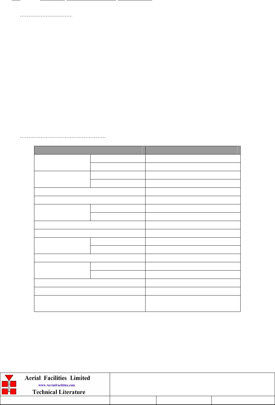
6.15.2 Technical Specification
PARAMETER SPECIFICATION
Operating voltage: 8 to 30V (floating earth)
Alarm Threshold: Vcc - 1.20 volt +15%
Alarm output relay contacts:
Max. switch current: 1.0Amp
Max. switch volts: 120Vdc/60VA
Max. switch power: 24W/60VA
Min. switch load: 10.0µA/10.0mV
Relay isolation: 1.5kV
Mechanical life: >2x10⁷ operations
Relay approval: BT type 56
Connector details: Screw terminals
operational: :-10°C to +55°C
Temperature range storage: :-40°C to +70°C
6.16 12 & 24V Single Relay Board (80-008901 & 80-008902)
6.16.1 Description
The General Purpose Single Relay Board allows the inversion of signals and the isolation of
circuits. It is equipped with a single dual pole change-over relay RL1, with completely
isolated wiring, accessed via a 15 way in-line connector.
The relay is provided with polarity protection diodes and diodes for suppressing the
transients caused by "flywheel effect" which can destroy switching transistors or induce
spikes on neighbouring circuits. It’s common use is to amalgamate all the alarm signals into
one, volts-free relay contact pair for the main alarm system.
Note that the board is available for different voltages (12 or 24V) depending on the type of
relay fitted at RL1.

Weehawken Tunnel 800MHz Repeater
User/Maintenance Handbook
Handbook N.-Weehawken_800 Issue No:-A
Date:-05/08/05 Page:-44 of 51
9. INSTALLATION
When this equipment is initially commissioned, please use the equipment set-up record sheet in
Appendix A. This will help both the installation personnel and AFL should these figures be
needed for future reference or diagnosis.
9.1 General Remarks
The size and weight of the equipment racks mean that they represent a significant topple hazard
unless they are securely bolted to the floor though the mounting holes in the base of the unit. In
the interests of safety this should be done before any electrical, RF, or optical connections are
made.
The equipment must be located on a flat, level surface that is made from a material suitable for
bearing the weight of the rack assembly. If the installer is in any doubt about the suitability of a
site it is recommended that he consult with an appropriately qualified Structural Engineer.
It is important in determining the location of the rack within the room that space is allowed for
access to the front and rear of the equipment. To enable maintenance to be carried out, the
doors must be able to fully open.
The location must be served with a duct to allow the entry of cables into the rack.
The mains power supply is connected to the terminal strip located on the bulkhead at the rear of
the equipment at floor level. It is recommended that the connection is made by a qualified
electrician, who must satisfy himself that the supply will be the correct voltage and of sufficient
capacity.
All electrical and RF connection should be completed and checked prior to power being
applied for the first time.

Weehawken Tunnel 800MHz Repeater
User/Maintenance Handbook
Handbook N.-Weehawken_800 Issue No:-A
Date:-05/08/05 Page:-45 of 51
9.2 RF Connections
All RF connections are made to the cable termination, located on the bulkhead at the rear of the
equipment at floor level. Care must be taken to ensure that the correct connections are made
with particular attention made to the base station TX/RX ports. In the event that the base
transmitter is connected to the RX output of the rack, damage to the equipment will be done if
the base station transmitter is then keyed.
Ensure that connections are kept clean and are fully tightened.
9.3 Commissioning
Once all connections are made the equipment is ready for commissioning.
To commission the system the test equipment detailed in Section 10.2 will be required.
Using the system diagrams and the end-to-end test specification, the equipment should be
tested to ensure correct operation. Typical RF levels that are not listed in the end-to-end
specification, such as input levels to the fibre transmitters are detailed in the maintenance
section of this manual.
On initial power up the system alarm indicators on the front panels of the equipment should be
checked. A red LED illuminated indicates a fault in that particular shelf that must be
investigated before proceeding with the commissioning. A green LED on each shelf
illuminates, to indicate that the power supply is connected to the shelf.
In the event that any part of the system does not function correctly as expected, check all
connections to ensure that they are to the correct port, that the interconnecting cables are not
faulty and that they are tightened. The majority of commissioning difficulties arise from
problems with the interconnecting cables and connectors.

Weehawken Tunnel 800MHz Repeater
User/Maintenance Handbook
Handbook N.-Weehawken_800 Issue No:-A
Date:-05/08/05 Page:-46 of 51
10. MAINTENANCE
10.1 Fault Finding
10.1.1 Quick Fault Checklist
All AFL equipment is individually tested to specification prior to despatch. Failure of this type
of equipment is not common. Experience has shown that a large number of fault conditions
relating to tunnel installations result from simple causes often occurring as result of
transportation, unpacking and installation. Below are listed some common problems which have
resulted in poor performance or an indicated non-functioning of the equipment.
• Mains power not connected or not switched on.
• External connectors not fitted or incorrectly fitted.
• Internal connectors becoming loose due to transport vibration.
• Wiring becoming detached as a result of heavy handling.
• Input signals not present due to faults in the aerial and feeder system.
• Base transmissions not present due to fault at the base station.
• Modems fitted with incorrect software configuration.
• Changes to channel frequencies and inhibiting channels.
• Hand held radio equipment not set to repeater channels.
• Hand held radio equipment not set to correct base station.
10.1.2 Fault Isolation
In the event that the performance of the system is suspect, a methodical and logical approach to
the problem will reveal the cause of the difficulty. The System consists of modules fitted in a
wall-mounted, environmentally protected enclosure.
Transmissions from the main base stations are passed though the system to the mobile radio
equipment; this could be a handheld radio or a transceiver in a vehicle. This path is referred to
as the downlink. The return signal path from the mobile radio equipment to the base station is
referred to as the uplink.
The first operation is to check the alarms of each of the active units and determine that the
power supplies to the equipment are connected and active.
This can be achieved remotely (via CEMS, the RS232 Coverage Enhancement Management
System, if fitted), or locally with the front panel LED’s. The green LED on the front panel
should be illuminated, while the red alarm indicator should be off. If an Alarm is on, then that
individual module must be isolated and individually tested against the original test
specification.
The individual amplifier units within the shelf have a green LED showing through a hole in
their piggy-back alarm board, which is illuminated if the unit is working correctly. If an
amplifier is suspect, check the DC power supply to the unit. If no other fault is apparent use a
spectrum analyser to measure the incoming signal level at the input and then after reconnecting
the amplifier input, measure the output level. Consult with the system diagram to determine the
expected gain and compare result.
In the event that there are no alarms on and all units appear to be functioning it will be
necessary to test the system in a systematic manner to confirm correct operation.

Weehawken Tunnel 800MHz Repeater
User/Maintenance Handbook
Handbook N.-Weehawken_800 Issue No:-A
Date:-05/08/05 Page:-47 of 51
10.1.3 Downlink
Confirm that there is a signal at the expected frequency and strength from the base station. If
this is not present then the fault may lay outside the system. To confirm this, inject a downlink
frequency signal from a known source at the master site BTS input and check for output at the
remote site feeder output.
If a signal is not received at the output it will be necessary to follow the downlink path through
the system to find a point at which the signal is lost. The expected downlink output for the
given input can be found in the end-to-end test specification.
10.1.4 Uplink
Testing the uplink involves a similar procedure to the downlink except that the frequencies
used are those transmitted by the mobile equipment.
10.1.5 Checking service
Following the repair of any part of the system it is recommended that a full end-to-end test is
carried out in accordance with the test specification and that the coverage is checked by survey.
It is important to bear in mind that the system includes a radiating cable network and base
stations that may be faulty or may have been damaged.

Weehawken Tunnel 800MHz Repeater
User/Maintenance Handbook
Handbook N.-Weehawken_800 Issue No:-A
Date:-05/08/05 Page:-48 of 51
10.1.6 Fault repair
Once a faulty component has been identified, a decision must be made on the appropriate
course to carry out a repair. A competent engineer can quickly remedy typical faults such as
faulty connections or cables. The exceptions to this are cable assemblies connecting bandpass
filter assemblies that are manufactured to critical lengths to maintain a 50-ohm system. Care
should be taken when replacing cables or connectors to ensure that items are of the correct
specification. The repair of component modules such as amplifiers and bandpass filters will not
usually be possible in the field, as they frequently require specialist knowledge and test
equipment to ensure correct operation. It is recommended that items of this type are replaced
with a spare unit and the faulty unit returned to AFL for repair.
10.1.7 Service Support
Advice and assistance with maintaining and servicing this system are available by contacting
Aerial Facilities Ltd.
NOTE
Individual modules are not intended to be repaired on site and attempts at repair will
invalidate active warranties. Company policy is that individual modules should be
repaired by replacement. Aerial Facilities Ltd maintains a high level of stock of most
modules which can usually be despatched at short notice to support this policy.
10.2 Tools & Test Equipment
The minimum tools and test equipment needed to successfully service this AFL product are as
follows:-
Spectrum analyser: 100kHz to 2GHz (Dynamic range = 90dB).
Signal Generator: 30MHz to 2GHz (-120dBm to 0dBm o/p level).
Attenuator: 20dB, 10W, DC-2GHz, (N male – N female).
Test Antenna: Yagi or dipole for operating frequency.
Digital multi-meter: Universal Volt-Ohm-Amp meter.
Test cable x 2: N male – N male, 2M long RG214.
Test cable x 2: SMA male – N male, 1m long RG223.
Hand tools: Philips #1&2 tip screwdriver.
3mm flat bladed screwdriver.
SMA spanner and torque setter.

Weehawken Tunnel 800MHz Repeater
User/Maintenance Handbook
Handbook N.-Weehawken_800 Issue No:-A
Date:-05/08/05 Page:-49 of 51
10.3 Care of Modules
10.3.1 General Comments
Many of the active modules contain semiconductor devices utilising MOS technology, which
can be damaged by electrostatic discharge. Correct handling of such modules is mandatory to
ensure their long-term reliability.
To prevent damage to a module, it must be withdrawn/inserted with care. The module may have
connectors on its underside, which might not be visible to the service operative.
10.3.2 Module Removal (LNA’s, general procedure):
The following general instructions should be followed to remove a module:
1 Remove power to the unit
2 Remove all visible connectors (RF, DC & alarm)
3 Release module retaining screws.
4 Slowly but firmly, pull the module straight out of its position. Take care not to twist/turn the
module during withdrawal. (When the module is loose, care may be needed, as there may be
concealed connections underneath).
10.3.3 Module Replacement (general):
1 Carefully align the module into its location then slowly push the module directly straight
into its position, taking care not to twist/turn it during insertion.
2 Reconnect all connectors, RF, alarm, power etc.,(concealed connectors may have to be
connected first).
3 Replace retaining screws (if any).
4 Double-check all connections before applying power.
10.3.4 Power Amplifiers
1) Remove power to the unit. (Switch off @ mains/battery, or remove DC in connector)
2) Remove alarm wires from alarm screw terminal block or disconnect multi-way alarm
connector.
3) Carefully disconnect the RF input and output coaxial connectors (usually SMA)
If alarm board removal is not required, go to step 5.
4) There is (usually) a plate attached to the alarm board which fixes it to the amplifier, remove
its retaining screws and the alarm board can be withdrawn from the amplifier in its entirety.
On certain types of amplifier the alarm board is not mounted on a dedicated mounting plate;
in this case it will have to firstly be removed by unscrewing it from the mounting pillars, in
most cases, the pillars will not have not have to be removed before lifting the amplifier.
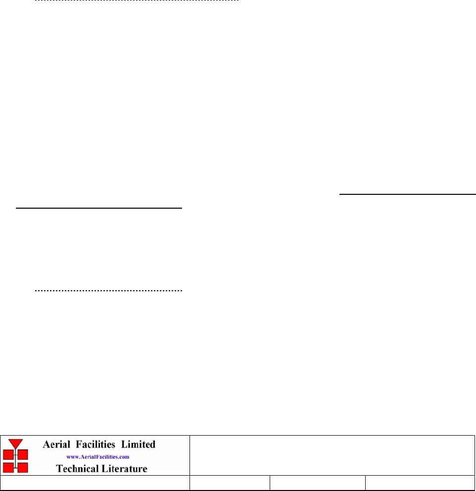
Weehawken Tunnel 800MHz Repeater
User/Maintenance Handbook
Handbook N.-Weehawken_800 Issue No:-A
Date:-05/08/05 Page:-50 of 51
5) If the amplifier to be removed has a heatsink attached, there may be several different ways it
can have been assembled. The most commonly used method, is screws through the front of
the heatsink to threaded screw holes (or nuts and bolts), into the amplifier within the main
case. If the heatsink is mounted on the rear of the main case (e.g., against a wall in the case
of wall mounted enclosures), then the fixing method for the heatsink will be from within the
case, (otherwise the enclosure would have to be removed from the wall in order to remove
the heatsink).
When the heatsink has been removed, the amplifier may be unscrewed from the main casing
by its four corner fixings and gently withdrawn.
Fitting a new power amplifier module will be the exact reverse of the above.
Note: Do not forget to apply fresh heatsink compound to the heatsink/main case joint
and also between the amplifier and the main case.
10.3.5 Low Power Amplifier Replacement
1 Disconnect the mains power supply and disconnect the 24V dc supply connector for the
LPA.
2 Disconnect the RF input and output cables from the LPA.
3 Disconnect the alarm connector.
4 Remove the alarm monitoring wires from (D type connector) pins 9 and 10.
5 Remove the LPA module by removing the four retaining screws, replace with a new LPA
module and secure it with the screws.
6 Connect the RF cables to the LPA input and output connectors. Reconnect the wires to the
alarm board connector pins 9 and 10.
7 Reconnect the DC supply connector and turn the mains switch on.
Note: Tighten SMA connectors using only a dedicated SMA torque spanner. If SMA
connectors are over-tightened, irreparable damage will occur. . Do not use adjustable pliers
to loosen/tighten SMA connectors.
Also take care not to drop or knock the module as this can damage (or misalign in the case
of tuned passive modules) sensitive internal components. Always store the modules in an
environmentally friendly location
10.3.6 Module Transportation:
To maintain the operation, performance and reliability of any module it must be stored and
transported correctly. Any module not installed in a whole system must be kept in an anti-static
bag or container. These bags or containers are normally identified by being pink or black, and
are often marked with an ESD label. Any module sent back to AFL for investigation/repair must
be so protected. Please contact AFL’s quality department before returning a module.
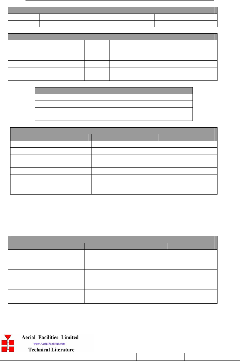
Weehawken Tunnel 800MHz Repeater
User/Maintenance Handbook
Handbook N.-Weehawken_800 Issue No:-A
Date:-05/08/05 Page:-51 of 51
APPENDIX A INITIAL EQUIPMENT SET-UP CALCULATIONS
GENERAL INFORMATION
Site Name: Client Name:
Date: AFL Equip. Model N.
ANTENNA SYSTEMS
Model Gain Azimuth Comments
A - Service Antenna
B – Donor Antenna
Type Loss Length Comments
C – Service Feeder
D – Donor Feeder
INITIAL PARAMETERS
E – CE Output Power dBm
F – Antenna Isolation dB
G – Input signal level from donor BTS dBm
Operating Voltage V
DOWNLINK CALCULATIONS
Parameter Comments Value
Input signal level (G) dBm
CE max. o/p power (E) dBm
Gain setting E - G dB
Isolation required (Gain + 10dB) dB
Service antenna gain (A) dB
Service antenna feeder loss (C) dB
Effective radiated power (ERP) E+A-C dBm
Attenuator setting CE gain-gain setting dB
If the input signal level in the uplink path is known and steady, use the following calculation
table to determine the gain setting. If the CE features Automatic Gain Control the attenuator
should be set to zero and if not, then the attenuation setting for both uplink and downlink
should be similar.
UPLINK CALCULATIONS
Parameter Comments Value
Input signal level dBm
CE max. o/p power (E) dBm
Gain setting dB
Required isolation dB
Donor antenna gain (B) dB
Donor antenna feeder loss (D) dB
Effective radiated power (ERP) E+B-D dBm
Attenuator setting (CE gain-gain setting) dB