Axell Wireless A215SERIES Dual Band Repeater MBF-D-8-19 User Manual manual
Axell Wireless Dual Band Repeater MBF-D-8-19 manual
UserManual.wiki
>
Axell Wireless
>
A215SERIES User Manual
manual
Navigation menu
Upload a User Manual
Namespaces
Wiki Guide
HTML
PDF
Info
Views
User Manual
Discussion / Help
Navigation
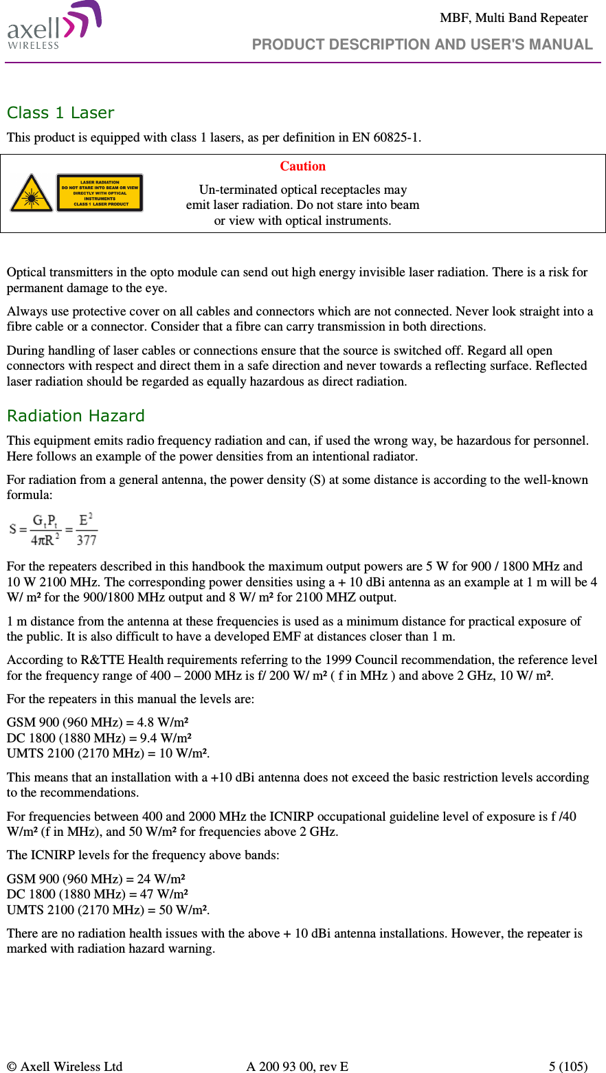
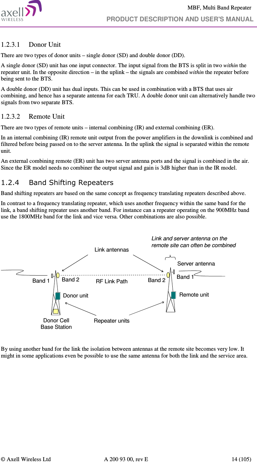
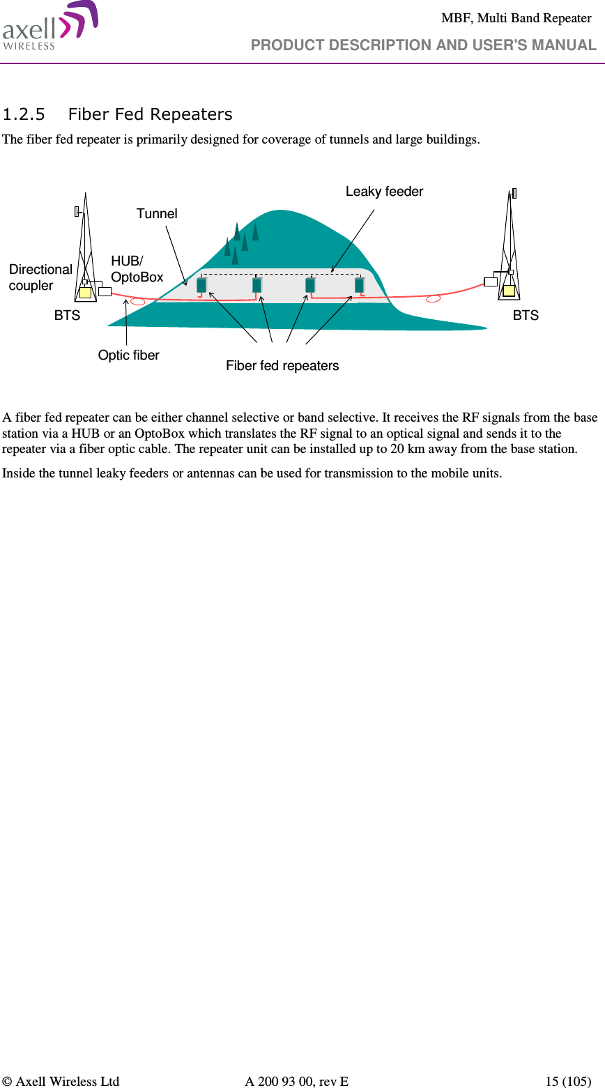
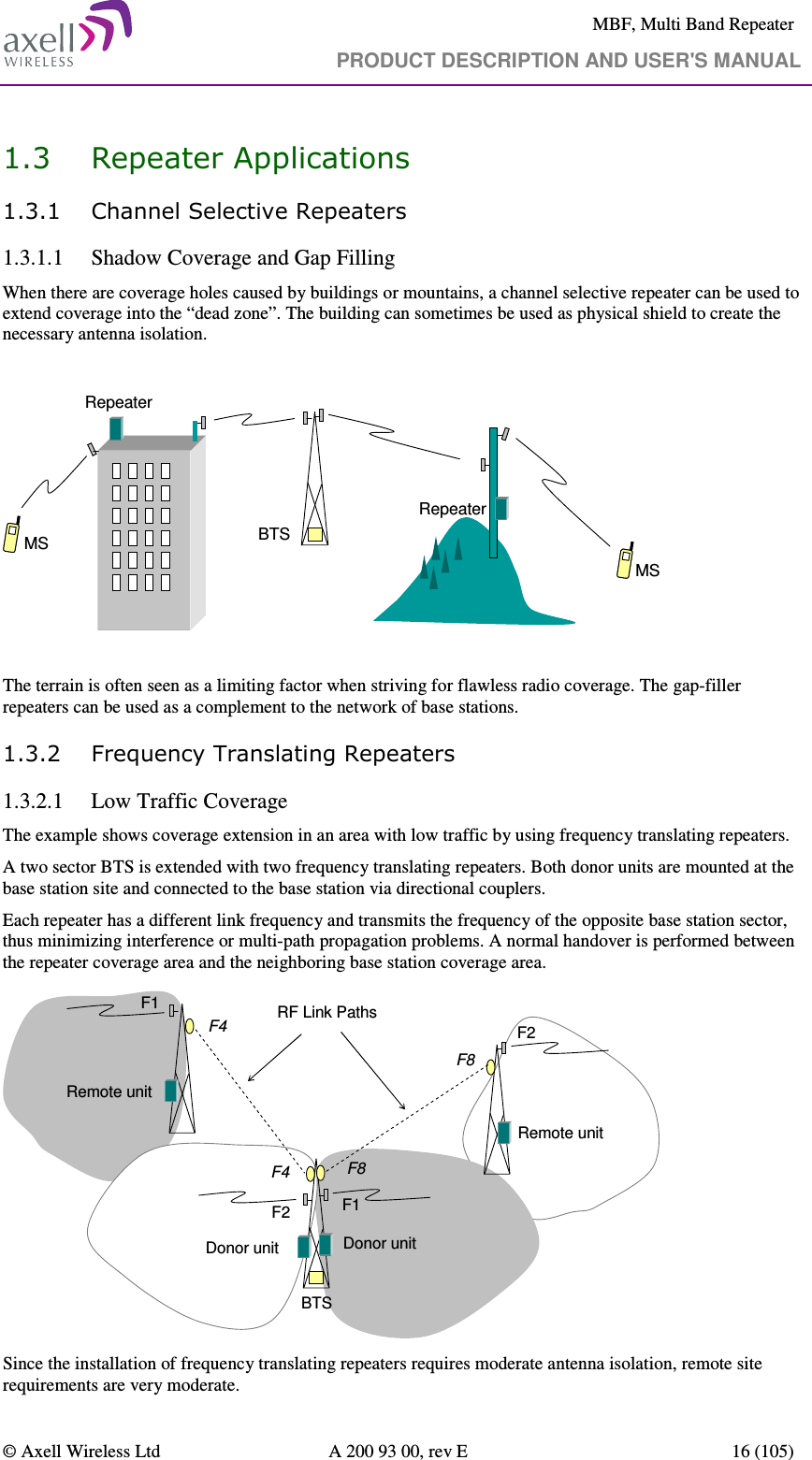
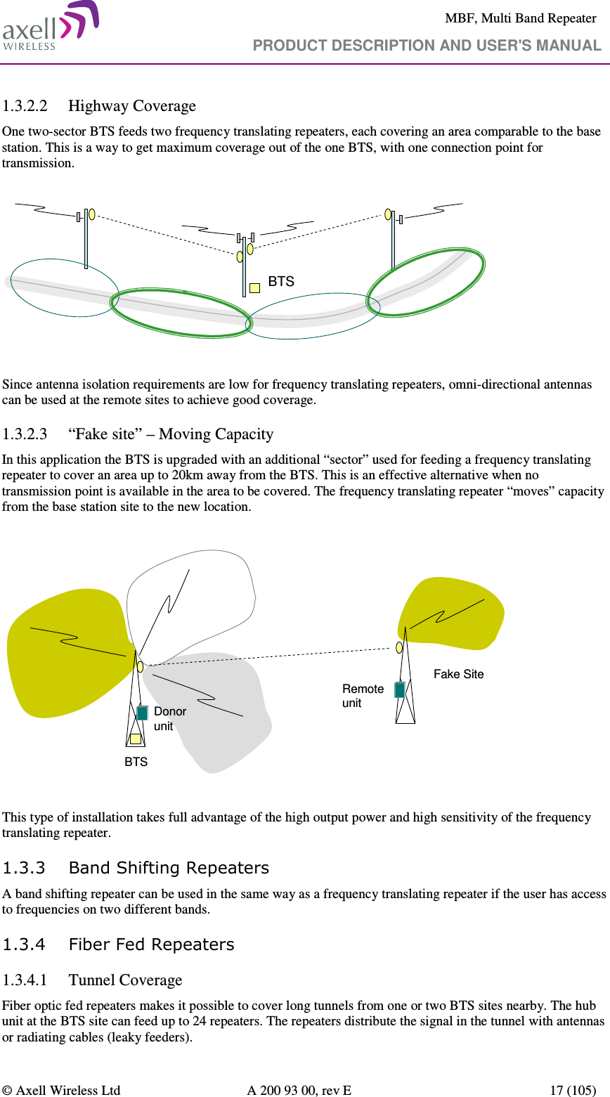
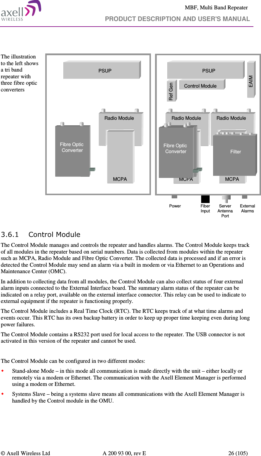
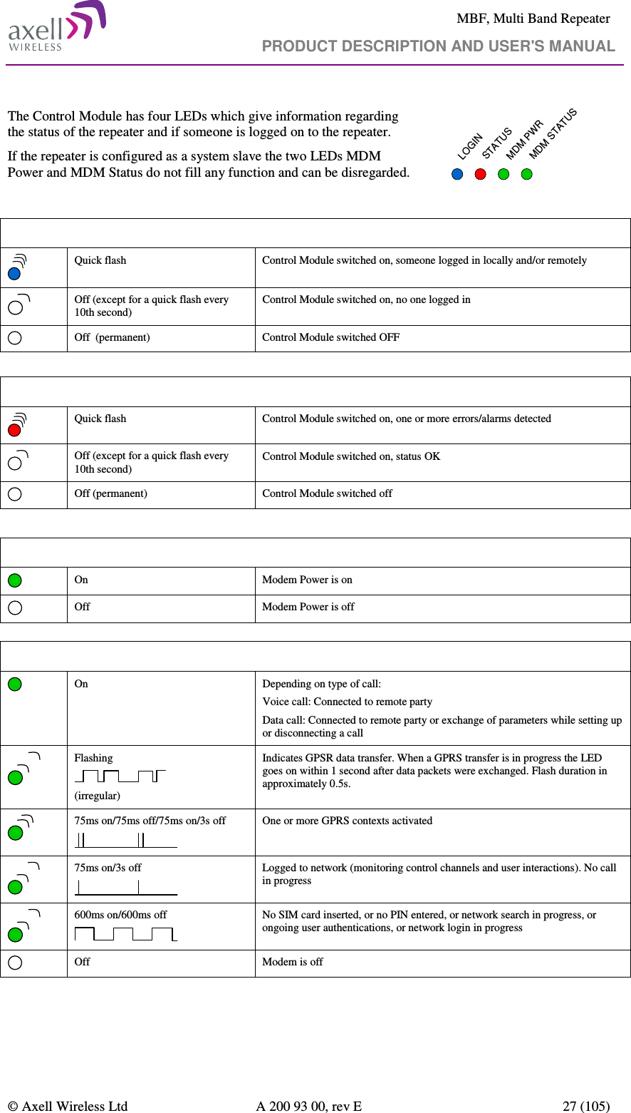
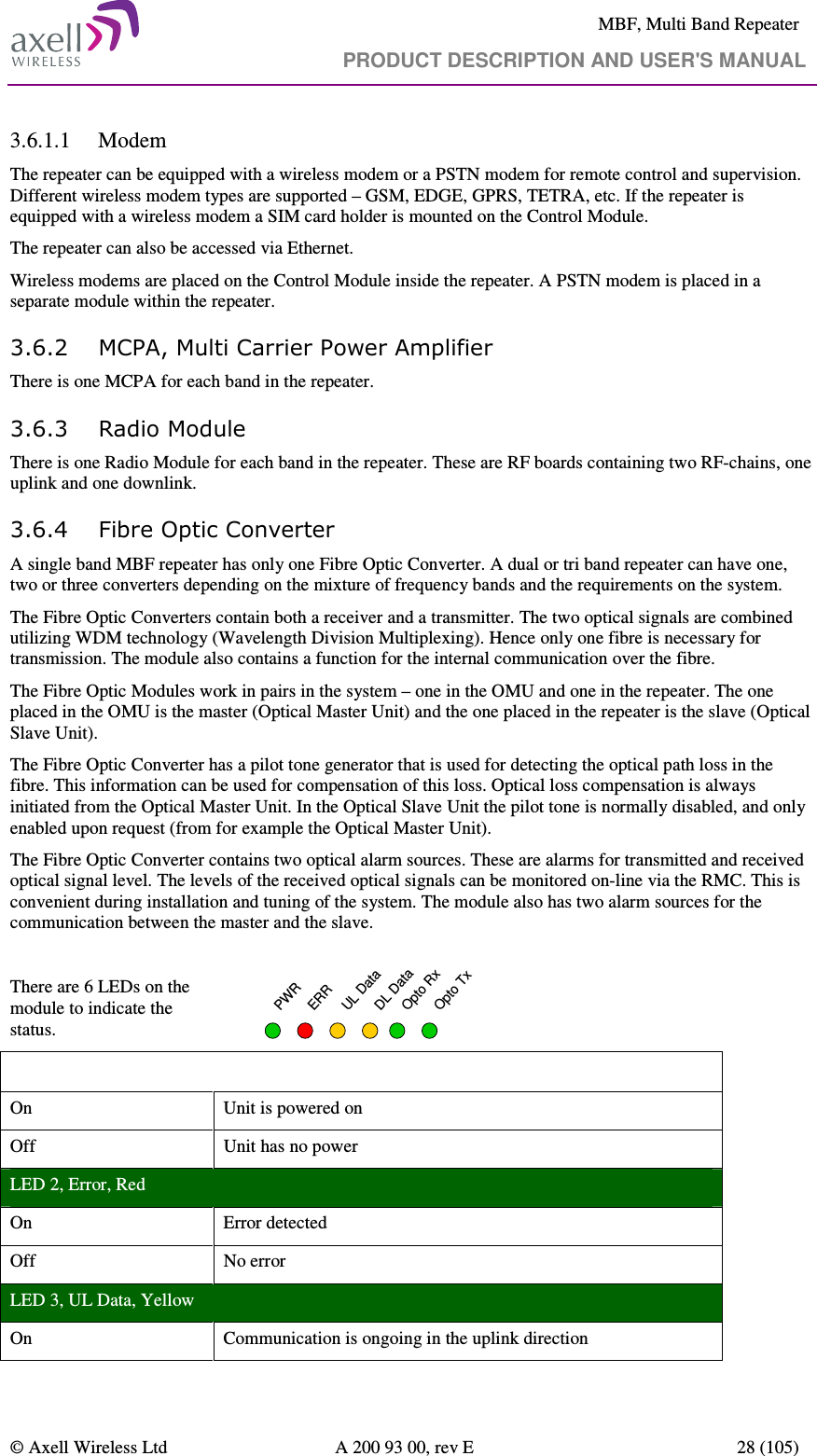
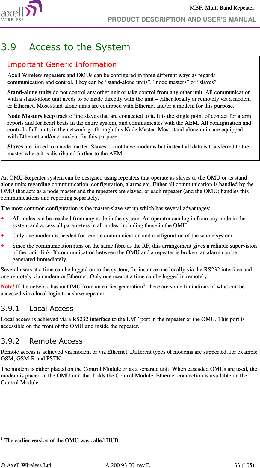
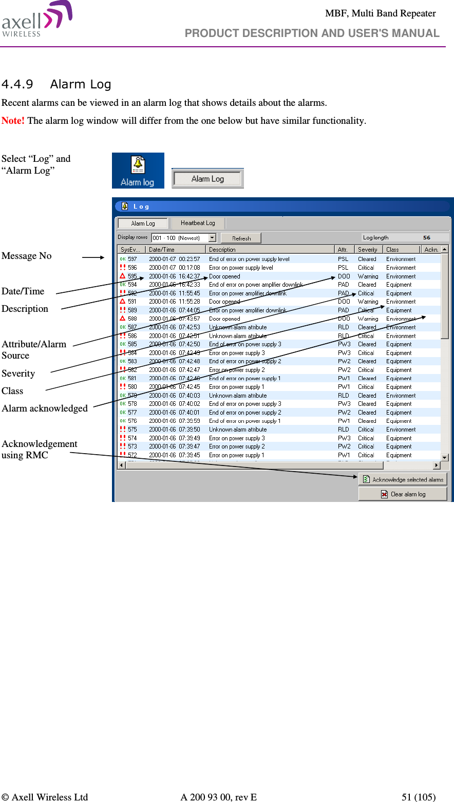
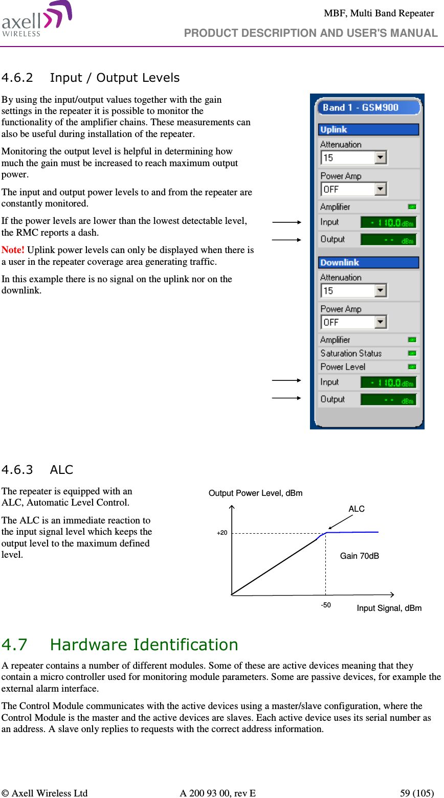
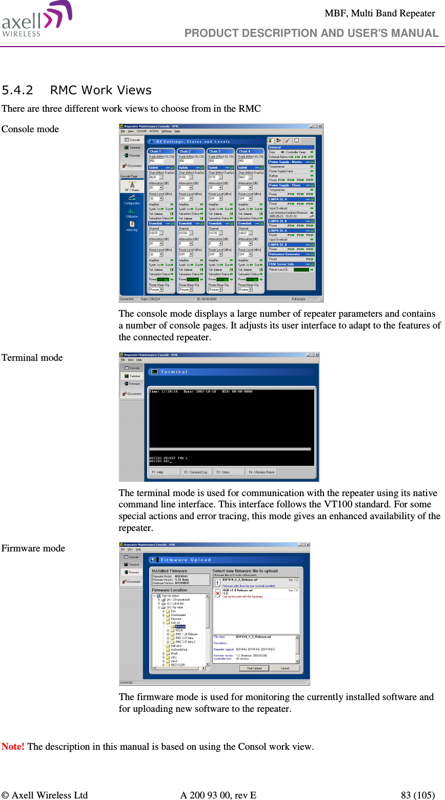
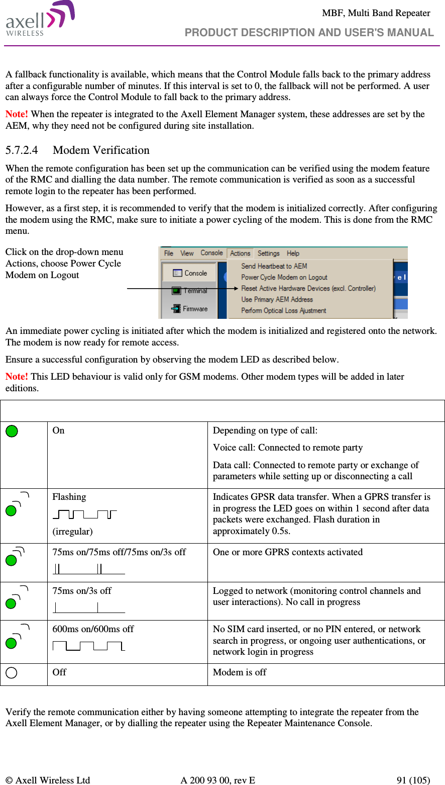
![MBF, Multi Band Repeater PRODUCT DESCRIPTION AND USER'S MANUAL © Axell Wireless Ltd A 200 93 00, rev E 37 (105) Serial Number Addressing A node can be accessed using the serial number of the node. Example: AVITEC AB> @2J34 GET MDL MBF-I AVITEC AB> Node ID Addressing A node can also be addressed using the full Node ID. Example: AVITEC AB> @01-01-2J34 GET TAG SITE3_TUNNEL_OPENING AVITEC AB> Direct Node Addressing When many attributes are intended for another node, the user can enter Direct Node Accessing mode, where the node the user is logged in redirects all commands to the destination node. This mode is configured by sending the command: SET DNA [Node Address] where any of the node addressing modes can be used as Node Address. When going into direct node addressing, the command prompt is changed to reflect what node is currently addressed: AVITEC AB> SET DNA 2J34 AVITEC AB @2J34> Refer to attribute DNA in OMU Command and Attribute Summary for further details on direct node addressing. 4.2.3 System Wide Parameters System Wide Parameters are parameters that when configured should be written to all nodes in the system. When setting a system wide parameter, the parameter is always set in the node master, which is then responsible for setting the parameter to all other nodes. If attempting to set a system wide parameter from a node as access to the node master is not available, setting the parameter will fail. The following “standard” parameters are treated as system wide parameters (please refer to OMU Command and Attribute Summary for details): LMT Local Maintenance Terminal timeout TIM Setting the time DAT Setting the date TPD Setting the time for sending traffic / utilization report to the AEM UID User ID’s PWD Passwords RID Repeater ID In slave repeaters the OMU is responsible for the communication with the AEM.](https://usermanual.wiki/Axell-Wireless/A215SERIES/User-Guide-1418816-Page-37.png)