Axell Wireless D2107L2017F Digital Multi-Band Mini Repeater User Manual
Axell Wireless Digital Multi-Band Mini Repeater Users Manual
Users Manual
The most important thing we build is trust
DIGImini
AMERICAS
Digital Multi-band Series
User Manual – 00031UM Rev. 6.3
DIGIMINI AMERICAS REPEATERS
PRODUCT DESCRIPTION AND USER’S MANUAL
Cobham Wireless – Coverage Date: 6-Jul-17 www.cobham.com/wireless
Doc. No.: 00031UM Rev. 6.3 Page | II
Copyright © 2017 Axell Wireless Limited trading as Cobham Wireless
All rights reserved.
No part of this document may be copied, distributed, transmitted, transcribed, stored in a retrieval system, or translated
into any human or computer language without the prior written permission of Axell Wireless Limited trading as Cobham
Wireless.
The manufacturer has made every effort to ensure that the instructions contained in this document are adequate and
free of errors and omissions. The manufacturer will, if necessary, explain issues which may not be covered by this
document. The manufacturer's liability for any errors in the document is limited to the correction of errors and the
aforementioned advisory services.
This document has been prepared to be used by professional and properly trained personnel, and the customer assumes
full responsibility when using them. The manufacturer welcomes customer comments as part of the process of continual
development and improvement of the documentation in the best way possible from the user's viewpoint. Please submit
your comments to the nearest Cobham Wireless sales representative.
Contact Information
Headquarters Axell Wireless trading as Cobham Wireless
Aerial House, Asheridge Road
Chesham, Buckinghamshire
HP5 2QD, United Kingdom
Tel: +44 1494 777000
Fax: +44 1494 777002
Commercial inquiries cw.coverage@cobham.com
Website www.cobham.com/wireless
Support issues cw.support@cobham.com
Technical Support Line, English speaking +44 1494 777 747
About This Manual
This Product Manual provides the following information:
• Description of the Repeater unit
• Procedures for setup, configuration and checking the proper operation of the unit
• Maintenance and troubleshooting procedures

DIGIMINI AMERICAS REPEATERS
PRODUCT DESCRIPTION AND USER’S MANUAL
Cobham Wireless – Coverage Date: 6-Jul-17 www.cobham.com/wireless
Doc. No.: 00031UM Rev. 6.3 Page | III
Ordering information and DIGImini Models to which this manual applies:
ORDERING INFORMATION for DIGImini Americas Repeaters
Identification Description Part Number
DIGI Mini 850&SMR800/1900 DIGI MINI 850&SMR800/1900 21/20 dBm 8 Filters D-MINI-2108CS-2019
DIGI Mini 700U/AWS1 DIGI MINI 700 Upper /AWS1 21/20 dBm 8 Filters D-MINI-2107U-2017
DIGI Mini AWS1+3 DIGI MINI AWS1&3 20 dBm 8 Filter SB D-MINI-2017F-SB
DIGI Mini 700l/AWS1+3 DIGI MINI 700 Lower /AWS1&3 21/20 dBm 8 Filters D-MINI-2107L-2017F
DIGI Mini AWS1/1900 DIGI MINI AWS1/1900 20/20 dBm 8 Filters D-MINI-2017-2019
DIGI Mini AWS1/2600 DIGI MINI AWS1/2600 20/20 dBm 8 Filters D-MINI-2017-2026
DMCU External DIGI MINI Control Unit with GPRS Modem DMCU
DMCU External DIGI MINI Control Unit with CDMA1X Modem DMCU-CDMA
DMCU External DIGI MINI Control Unit with WCDMA
(Telit 864) Modem DMCU-WCDMA
DIGI Mini Accessory Kit DIGI mini 4 bands Accessory upgrade kit D-MINI-4B-AK
Digi Mini 19" bracket Digi Mini 19" bracket D-MINI 19-BRKT

DIGIMINI AMERICAS REPEATERS
PRODUCT DESCRIPTION AND USER’S MANUAL
Cobham Wireless – Coverage Date: 6-Jul-17 www.cobham.com/wireless
Doc. No.: 00031UM Rev. 6.3 Page | IV
For whom it is intended
This Product Manual is intended for experienced technicians and engineers. It is assumed that the customers installing,
operating, and maintaining Cobham Wireless Repeaters are familiar with the basic functionality of Repeaters.
Notice
Confidential - Authorized Customer Use
This document may be used in its complete form only and is solely for the use of Cobham Wireless employees and
authorized Cobham Wireless channels or customers. The material herein is proprietary to Cobham Wireless. Any
unauthorized reproduction, use or disclosure of any part thereof is strictly prohibited.
All trademarks and registered trademarks are the property of their respective owners.
Disclaimer of Liability
Contents herein are current as of the date of publication. Cobham Wireless reserves the right to change the contents
without prior notice. The information furnished by Cobham Wireless in this document is believed to be accurate and
reliable. However, Cobham Wireless assumes no responsibility for its use. In no event shall Cobham Wireless be liable
for any damage resulting from loss of data, loss of use, or loss of profits and Cobham Wireless further disclaims any and
all liability for indirect, incidental, special, consequential or other similes damages. This disclaimer of liability applies to all
products, publications and services during and after the warranty period.
Safety Instructions and Warnings
Throughout this manual, important safety warnings and admonishments are included to warn of possible hazards to
persons or equipment. A safety warning identifies a possible hazard and then describes what may happen if the hazard
is not avoided. The safety warnings – in the form of Dangers, Warnings and Cautions must be followed at all times.
These warnings are flagged by the use of a warning icon, usually the triangular alert icon seen below. The exclamation
point within the triangular alert icon is intended to warn the operator or service personnel of operation and maintenance
from factors relating to the product and its operating environment, which could pose a safety hazard.
Guarantees
• All antennas must be installed with lightning protection. Damage to power modules, as a result of lightning are not
covered by the warranty.
• Switching on AC or DC power prior to the connection of antenna cables is regarded as faulty installation procedure
and therefore not covered by the Cobham Wireless warranty.
General Safety Warnings Concerning Use of This System
Always observe standard safety precautions during installation, operation and maintenance of this product.
Exclusive Remedies
The remedies provided herein are the Buyer’s sole and exclusive remedies. Cobham Wireless shall not be viable for any
direct, incidental, or consequential damages, whether based on contract, tort, or any legal theory.

DIGIMINI AMERICAS REPEATERS
PRODUCT DESCRIPTION AND USER’S MANUAL
Cobham Wireless – Coverage Date: 6-Jul-17 www.cobham.com/wireless
Doc. No.: 00031UM Rev. 6.3 Page | V
Compliance with FCC
WARNING!! This is NOT a CONSUMER device. This device is designed for installation by
FCC LICENCEES and QUALIFIED INSTALLERS. You must have an FCC LICENCE or express
consent of an FCC Licensee to operate this device.
Unauthorized use may result in significant forfeiture penalties, including penalties in excess
of $100,000 for each continuing violation.
FCC Part 15
This device complies with part 15 of the FCC Rules. Operation is subject to the following two conditions:
1. This device may not cause harmful interference, and
2. This device must accept any interference received, including interference that may cause undesired
operation.
If not installed and used in accordance with the instructions, this equipment generates, uses and can radiate
radio frequency energy. However, there is no guarantee that interference will not occur in a particular
installation. If this equipment does cause harmful interference to RF reception, which can be determined by
turning the equipment off and on, the user is encouraged to try to correct the interference by one or more
of the following measures:
• Reorient or relocate the Donor antenna.
• Increase the separation between the equipment and receiver.
• Connect the equipment into an outlet on a circuit different from that to which the receiver is connected.
Unauthorized Changes to Equipment
Changes or Modifications not expressly approved by the manufacturer responsible for compliance could void
the user’s authority to operate the equipment
FCC RF Exposure Limits
This unit complies with FCC RF exposure limits for an uncontrolled environment. This equipment must be
installed and operated with a minimum distance of 20cm between the radiator and any person’s body.
Antenna Installation
Installation of an antenna must comply with the FCC RF exposure requirements. The antenna used for this
transmitter must be mounted on outdoor or indoor permanent structures.
The maximum antenna gain for indoor operation is 2.2 dBi and for the external antenna is 9dBi. Cable loss
of at least 2dB is taken into account for all cases.
Antennas having a gain greater than these are strictly prohibited for use with this device. In indoor
applications the antenna must be installed at a minimum separation distance of 20cm from all nearby
persons.
DIGIMINI AMERICAS REPEATERS
PRODUCT DESCRIPTION AND USER’S MANUAL
Cobham Wireless – Coverage Date: 6-Jul-17 www.cobham.com/wireless
Doc. No.: 00031UM Rev. 6.3 Page | VI
Compliance with IC
WARNING!! This is NOT a CONSUMER device. It is designed for installation by an installer
approved by an ISED licensee. You MUST have an ISED LICENCE or the express consent of
an ISED licensee to operate this device.
Under Industry Canada regulations, this radio transmitter may only operate using an antenna of a type and
maximum (or lesser) gain approved for the transmitter by Industry Canada. To reduce potential radio
interference to other users, the antenna type and its gain should be so chosen that the equivalent
isotropically radiated power (e.i.r.p.) is not more than that necessary for successful communication.
Conformément à la réglementation d'Industrie Canada, le présent émetteur radio peut fonctionner avec une
antenne d'un type et d'un gain maximal (ou inférieur) approuvé pour l'émetteur par Industrie Canada. Dans
le but de réduire les risques de brouillage radioélectrique à l'intention des autres utilisateurs, il faut choisir le
type d'antenne et son gain de sorte que la puissance isotrope rayonnée équivalente (p.i.r.e.) ne dépasse pas
l'intensité nécessaire à l'établissement d'une communication satisfaisante.
The Manufacturer's rated output power of this equipment is for single carrier operation. For situations when
multiple carrier signals are present, the rating would have to be reduced by 3.5 dB, especially where the
output signal is re-radiated and can cause interference to adjacent band users. This power reduction is to be
by means of input power or gain reduction and not by an attenuator at the output of the device.
This equipment complies with IC RSS-102 radiation exposure limits set forth for an uncontrolled
environment. This equipment should be installed and operated with minimum distance 20cm between the
antenna and your body.
La puissance de sortie nominale indiquée par le fabricant pour cet appareil concerne son fonctionnement
avec porteuse unique. Pour des appareils avec porteuses multiples, on doit réduire la valeur nominale de 3.5
dB, surtout si le signal de sortie est retransmis et qu'il peut causer du brouillage aux utilisateurs de bandes
adjacentes. Une telle réduction doit porter sur la puissance d'entrée ou sur le gain, et ne doit pas se faire au
moyen d'un atténuateur raccordé à la sortie du dispositif.
Cet appareil est conforme aux limitations de la norme IC RSS-102 concernant l’exposition aux radiations
dans un environnement non contrôlé. Cet appareil doit être installé et utilisé avec une distance minimale de
20cm entre l’antenne et le corps de l’utilisateur.
Conforme aux CNR
Le présent appareil est conforme aux CNR d’Industrie Canada applicables aux appareils radio exempts
de licence. L’exploitation est autorisée aux deux conditions suivantes :
1) l’appareil ne doit pas produire de brouillage;
2) l’utilisateur de l’appareil doit accepter tout brouillage radioélectrique subi, même si le brouillage est
susceptible d’en compromettre le fonctionnement.
Required for the installation/ Requis par l'installation
The installation must comply with directives provided in the following link / L'installation doit être
conforme aux directives fournies dans le lien suivant:
http://www.ic.gc.ca/eic/site/smt-gst.nsf/eng/sf08942.html
DIGIMINI AMERICAS REPEATERS
PRODUCT DESCRIPTION AND USER’S MANUAL
Cobham Wireless – Coverage Date: 6-Jul-17 www.cobham.com/wireless
Doc. No.: 00031UM Rev. 6.3 Page | VII
General Safety Warnings Concerning
Always observe standard safety precautions during installation, operation and maintenance of this product.
Caution labels!
Throughout this manual, there are "Caution" warnings. "Caution" calls attention
to a procedure or practice, which, if ignored, may result in injury or damage to
the system, system component or even the user. Do not perform any procedure
preceded by a "Caution" until the described conditions are fully understood and
met.
Danger: Electrical
Shock
To prevent electrical shock when installing or modifying the system power wiring,
disconnect the wiring at the power source before working with un insulated wires
or terminals.
Caution: Safety to
personnel
•
Before installing or replacing any of the equipment, the entire manual should be
read and understood.
•
The user needs to supply the appropriate AC or DC power to the repeater.
Incorrect power settings can damage the repeater and may cause injury to the
user.
•
Please be aware that the equipment may, during certain conditions become
very warm and can cause minor injuries if handled without any protection, such
as gloves.
Caution: Safety to
equipment
•
When installing, replacing or using this product, observe all safety precautions
during handling and operation. Failure to comply with the following general
safety precautions and with specific precautions described elsewhere in this
manual violates the safety standards of the design, manufacture, and intended
use of this product.
•
Changes or modifications not expressly approved by the party responsible
•
for compliance could void the user’s authority to operate the equipment
•
Axell Wireless assumes no liability for the customer's failure to comply with
these precautions. This entire manual should be read and understood before
operating or maintaining the repeater.
Warning: Restricted
Access Location
Access to the Axell unit installation location is restricted to SERVICE PERSONNEL
and to USERS who have been instructed on the restrictions and the required
precautions to be taken.
Attention: Electrostatic
Sensitivity
•
Observe electrostatic precautionary procedures.
•
ESD = Electrostatic Discharge Sensitive Device.
•
Static electricity can be conducted to the semiconductor chip from the centre
pin of the RF input connector, and through the AC connector pins. When
unpacking and otherwise handling the repeater, follow ESD precautionary
procedures including use of grounded wrist straps, grounded workbench
surfaces, and grounded floor mats.

DIGIMINI AMERICAS REPEATERS
PRODUCT DESCRIPTION AND USER’S MANUAL
Cobham Wireless – Coverage Date: 6-Jul-17 www.cobham.com/wireless
Doc. No.: 00031UM Rev. 6.3 Page | VIII
Table of Contents
1 SYSTEM DESCRIPTION .............................................................................................. 1-1
1.1 Features and Capabilities .................................................................................................... 1-2
1.2 Single Unit and Dual-Unit Installations ................................................................................ 1-3
1.3 Single Band Unit Upgradeable to Dual-band ........................................................................ 1-3
1.4 Smart-ALC Function ............................................................................................................ 1-3
1.5 DMCU - Optional .................................................................................................................. 1-3
1.6 DIGImini Interfaces .............................................................................................................. 1-4
1.6.1 Front Panel Interfaces ................................................................................................ 1-4
1.6.2 Side Panel Interfaces ................................................................................................. 1-5
1.6.3 DIGImini Power Supply .............................................................................................. 1-5
2 ANTENNA AND REPEATER INSTALLATION REQUIREMENTS ..................................... 2-1
2.1 Base (Donor) Antenna Requirements .................................................................................. 2-1
2.1.1 Required Antenna Information .................................................................................... 2-1
2.1.2 Donor Antenna specifications ..................................................................................... 2-1
2.1.3 Installation Criteria ..................................................................................................... 2-2
2.2 Service Antenna Requirements ........................................................................................... 2-2
2.2.1 Required Antenna Information .................................................................................... 2-2
2.2.2 Recommended Antennas ........................................................................................... 2-2
2.2.3 Service Antenna Installation Criteria ............................................................................ 2-2
2.3 Repeater Pre-Installation Requirements............................................................................... 2-3
2.3.1 Safety Guidelines ...................................................................................................... 2-3
2.3.2 Required BTS Information .......................................................................................... 2-3
2.3.3 Criteria for Repeater Installation Location .................................................................... 2-3
2.3.4 RF Cable Installation Guidelines ................................................................................. 2-3
3 SINGLE UNIT REPEATER INSTALLATION .................................................................. 3-1
3.1 Overview ............................................................................................................................. 3-1
3.2 Required Tools and Materials .............................................................................................. 3-1
3.3 DIGImini Single Unit Kit ....................................................................................................... 3-2
3.4 Mounting the Repeater ........................................................................................................ 3-3
3.5 Before Connecting the Antennas or Power .......................................................................... 3-5
3.5.1 Verifying Donor and Service Antennas Isolation ........................................................... 3-6
3.5.2 Verifying Link between the BTS and the Repeater ........................................................ 3-6
3.6 Antenna Connections .......................................................................................................... 3-7
3.7 Power Up............................................................................................................................. 3-8
3.8 What Next? .......................................................................................................................... 3-8
4 QUAD-BAND REPEATER INSTALLATION ................................................................... 4-1
4.1 Overview ............................................................................................................................. 4-1
4.2 View of the Dual Unit Installation ......................................................................................... 4-2
4.3 Required Tools and Materials .............................................................................................. 4-2
4.4 DIGImini Tri/Quad-band Kit .................................................................................................. 4-3
4.4.1 Top Layer Items ........................................................................................................ 4-3
4.4.2 Middle layer Items ..................................................................................................... 4-4
4.4.3 Bottom Layer Items ................................................................................................... 4-4
4.4.4 Additional Items......................................................................................................... 4-5
4.5 Upgrading to a Quad-Band System ...................................................................................... 4-5
4.5.1 Assemble the DIGImini Units ...................................................................................... 4-5

DIGIMINI AMERICAS REPEATERS
PRODUCT DESCRIPTION AND USER’S MANUAL
Cobham Wireless – Coverage Date: 6-Jul-17 www.cobham.com/wireless
Doc. No.: 00031UM Rev. 6.3 Page | IX
4.5.2 Choosing the Appropriate Plate ................................................................................ 4-10
4.5.3 Connect SMA Jumper Cables ................................................................................... 4-13
4.5.4 Mount and Secure Quad-Band Assembly .................................................................. 4-14
4.6 Before Connecting the Antennas or Power ........................................................................ 4-16
4.7 Antenna Connections ........................................................................................................ 4-16
4.8 Power Up........................................................................................................................... 4-17
4.9 What Next? ........................................................................................................................ 4-17
5 SETUP AND CONFIGURATION ................................................................................... 5-1
5.1 Open a Direct Local Web Session to the Repeater ............................................................... 5-1
5.1.1 Connect the Computer to the Repeater........................................................................ 5-2
5.1.2 Configure the Computer’s Network Parameters ............................................................ 5-3
5.1.3 Login to the Repeater ................................................................................................ 5-5
5.2 Navigating the Web GUI Application .................................................................................... 5-6
5.2.1 Band Pane and Tabs ................................................................................................. 5-7
5.2.2 Operation Buttons ..................................................................................................... 5-7
5.3 Signal Levels and Channel Configuration ............................................................................ 5-7
5.3.1 RF Gain Setting Criteria ............................................................................................. 5-8
5.3.2 Bandwidth and the Number of Available Sub-Bands ..................................................... 5-8
5.3.3 Adjusting the Signal Levels and Configuring Channels .................................................. 5-9
6 ADMINISTRATION, MONITORING AND TROUBLESHOOTING ...................................... 6-1
6.1 Administrative Operations ................................................................................................... 6-1
6.1.1 License File Upload ................................................................................................... 6-1
6.1.2 Dual-band Support .................................................................................................... 6-2
6.1.3 Connection to an Ethernet Network ............................................................................. 6-3
6.1.4 Connection to an External Modem .............................................................................. 6-4
6.2 Monitoring and Troubleshooting ......................................................................................... 6-5
6.2.1 Repeater Alarms and Troubleshooting ......................................................................... 6-5
6.2.2 DIGImini LED Troubleshooting.................................................................................... 6-7
Appendix A: Specifications ................................................................................................... 1
DIGIMINI AMERICAS REPEATERS
PRODUCT DESCRIPTION AND USER’S MANUAL
Cobham Wireless – Coverage Date: 6-Jul-17 www.cobham.com/wireless
Doc. No.: 00031UM Rev. 6.3 Page | 1-1
1 SYSTEM DESCRIPTION
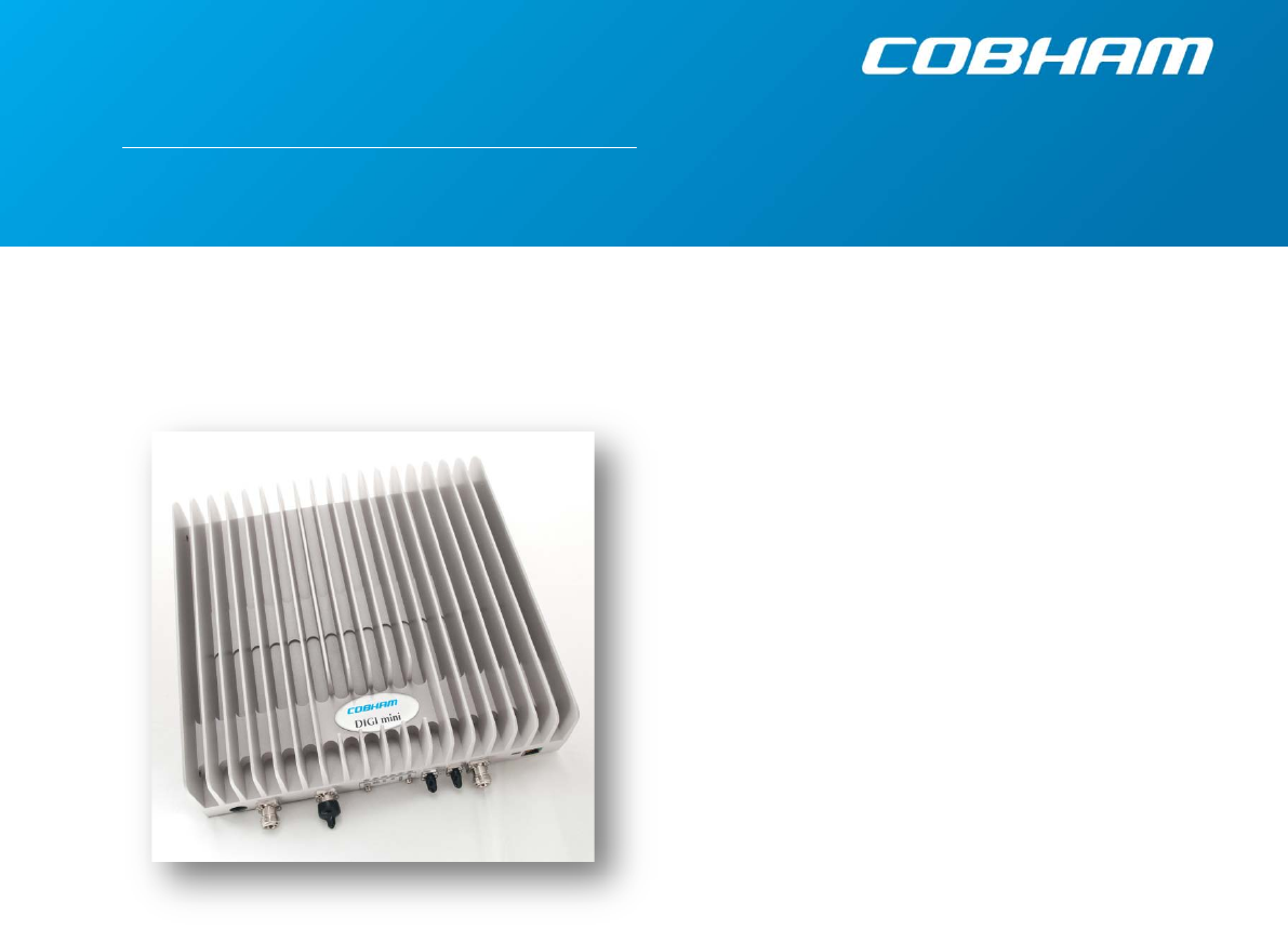
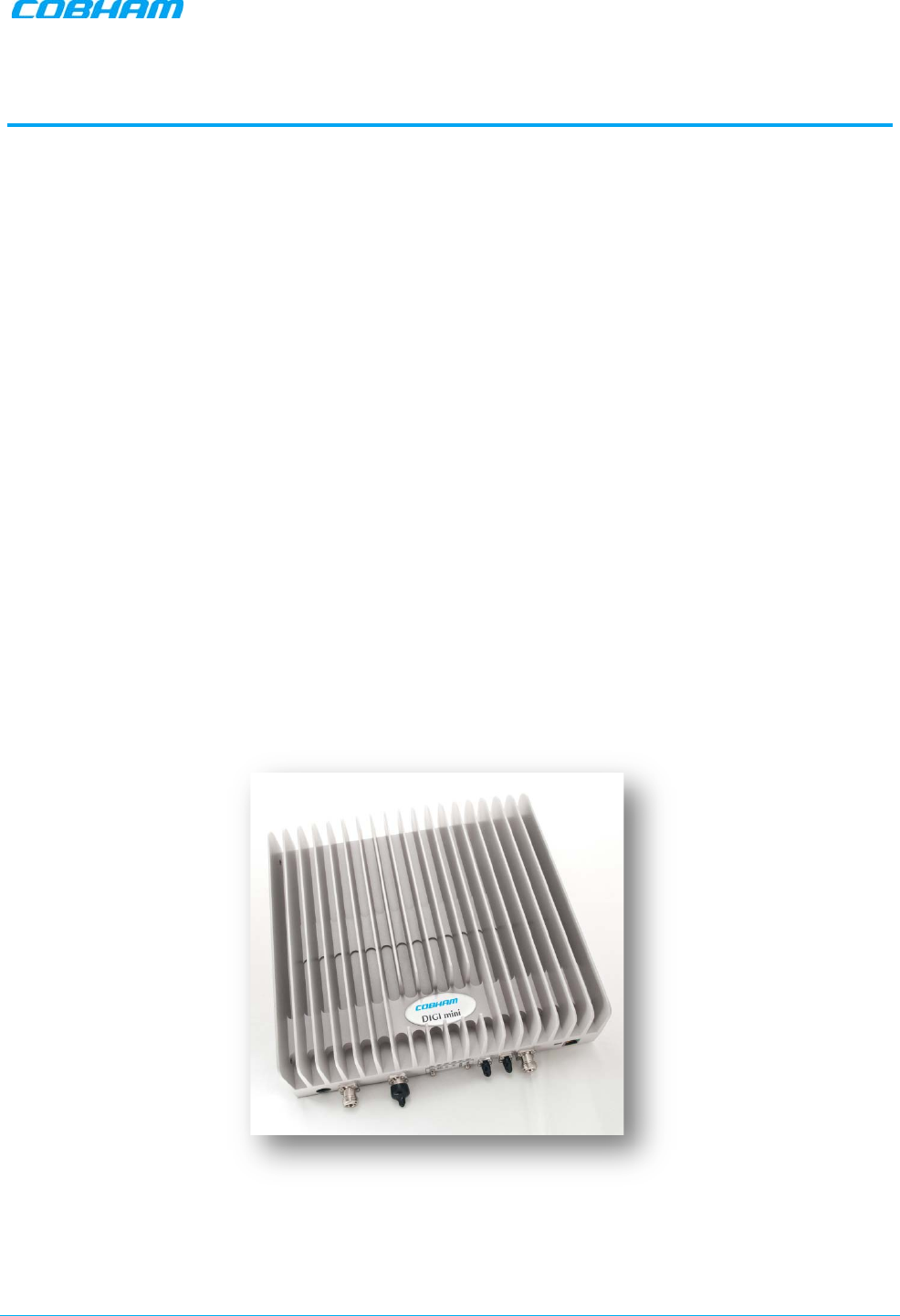
Cobham Wireless’ new DIGImini repeater (digital mini repeater) is an innovative flexible multiband coverage
solution optimized for in-building applications.
Cobham Wireless’ DIGImini offers a completely new range of possibilities. With multi technology (e.g
GSM/WCDMA/LTE) applications, multiple filters are required in the operation bands. The DIGImini is
designed to provide high performance digital filters with a competitive price when compared to legacy
analogue mini repeaters.
Up to four different frequency bands can be implemented in two dual band DIGImini repeaters.
Each DIGImini repeater is available in a range of single-band and dual-band models, where specific single-
band models can be updated to dual-band (requires license).
Easy “plug and play” allows our customers to add services as needed, thus minimizing their CAPEX. Software
Defined Filtering of up to 8 sub-bands in each dual band configuration and up to 16 sub-bands for quad
band configuration.
Individual Gain and ALC settings for each sub-band for multi-technology applications (e.g. GSM/
WCDMA/LTE), as well as for single and multi-operator applications.
A state-of-the-art Interference Mitigation and Oscillation Prevention (IMOP) algorithm is used to measure the
isolation between the antennas and gain is reduced immediately to prevent oscillation.
The DIGImini is connected to one donor antenna placed on the roof of the building and the radiating coaxial
cable or antennas in the area to be covered. Configuration and monitoring of the DIGImini can be done
through an intuitive web management GUI. Remote management is done via optional wireless modem.
With the Cobham Wireless advanced supervision and control software -AEM, the entire fleet of digital
multiband repeaters can be monitored.
Figure 1-1. Cobham Wireless DIGImini Repeater

DIGIMINI AMERICAS REPEATERS
PRODUCT DESCRIPTION AND USER’S MANUAL
Cobham Wireless – Coverage Date: 6-Jul-17 www.cobham.com/wireless
Document number: 00031UM Rev. 6.3 Page |1-2
1.1 Features and Capabilities
• Up to four frequency bands in two compact enclosures
• Software defined filtering of up to 8 sub-bands (up to 16 sub-bands per quad-band system)
• Individual gain and ALC settings for each sub-band for single and multi-operator applications.
• SmartALC™ technology per sub-band:
• Automatically sets optimum gain
• Prevents oscillations and balances coverage
• Ensures transparent network operation
• Supports multi-operator functionality
• Lightweight and compact footprint for easy installation
• Continuously monitors and adapts to the RF environment via Auto gain feature
• Easy commissioning and setup via web-based browser
• Optional DIGImini External modem– provides complete remote control and monitoring capabilities:
• WCDMA/GPRS modem support
• SMS messages
• Ethernet network connection and SNMP traps
• Battery backup – “last gasp” error reporting to AEM
• Optional upgrades via a purchased license file* (relevant for specific models):
• Single band models can be upgraded to support dual-band.
• Upgrade to support basic remote monitoring options via direct Ethernet connection to the
network (supports SNMP traps) or connection to an external modem. *
* Upgrade options for single-band to dual-band software upgrade and for remote monitoring (Ethernet network or external modem) are
implemented using two different licenses.

DIGIMINI AMERICAS REPEATERS
PRODUCT DESCRIPTION AND USER’S MANUAL
Cobham Wireless – Coverage Date: 6-Jul-17 www.cobham.com/wireless
Document number: 00031UM Rev. 6.3 Page |1-3
1.2 Single Unit and Dual-Unit Installations
DIGImini installation varies depending on whether one or two units are installed:
• Single DIGImini unit (supports single-band or dual-band) – details in Chapter 3.
• Dual DIGImini assembly (up to four bands) – details in Chapter 4
1.3 Single Band Unit Upgradeable to Dual-band
Single-band units can be upgraded to support two bands by acquiring the appropriate license file from
Cobham Wireless support team.
1.4 Smart-ALC Function
The Smart Automatic Level Control (Smart-ALC) is an innovative algorithm for automatic repeater gain
adjustment per sub-band.
Combined with advanced control algorithms, SALC is capable of learning the traffic load characteristics and
adjusting the Repeater RF Gain to the desired value.
Smart ALC eliminates the need to perform initial settings for maximal traffic load conditions and on-site gain
adjustments.
Smart-ALC maintains the Uplink/Downlink gain balance for system transparency. In addition, Smart-ALC
prevents oscillations that may occur due to insufficient isolation while maintaining the gain in a linear range
operation by adjusting the repeater paths’ gain accordingly.
IMOP (Isolation Measurement and Oscillation Prevention) algorithm effectively reduces oscillation problems.
The repeater’s power amplifier includes power-monitoring circuits with Automatic Level Control (ALC) that
prevents excessive output power while maintaining the power amplifier linearity.
1.5 DMCU - Optional
The DMCU (DIGImini Control Unit) provides complete remote control and monitoring capabilities over
WCDMA/GPRS, including Remote control via SMS.
The DMCU is an optional control unit that is ordered separately and is installed
externally
, where one DMCU
can support a single DIGImini unit as well as an a DIGImini Quad-band assembly.
NOTE: Refer to the DMCU User Manual for the complete description of the DMCU and the configuration and
management capabilities provided by the unit.
DIGIMINI AMERICAS REPEATERS
PRODUCT DESCRIPTION AND USER’S MANUAL
Cobham Wireless – Coverage Date: 6-Jul-17 www.cobham.com/wireless
Document number: 00031UM Rev. 6.3 Page |1-4
1.6 DIGImini Interfaces
The DIGImini is supplied in two physical configurations:
• Single unit supporting (one or) two bands;
• Two cascaded units supporting up to four bands.
Power supplies
dedicated to each unit
are connected externally. An optional DMCU supporting an external
modem is also connected externally, where a single DMCU can serve two cascaded units.
The interfaces are located on the
front
and on the
side
panels.
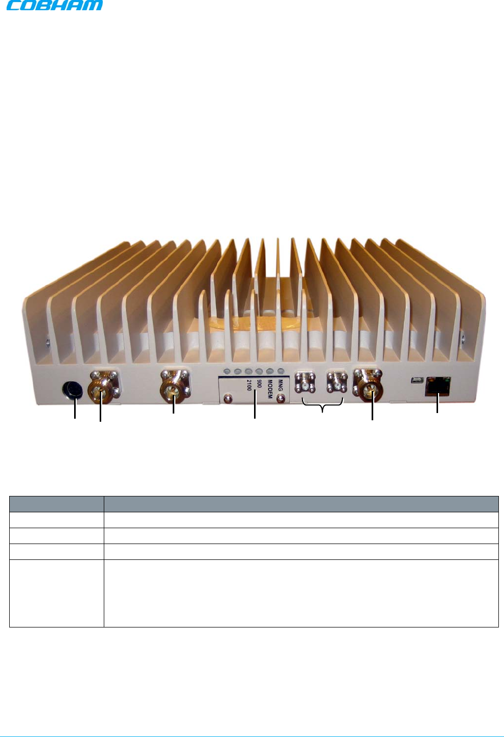
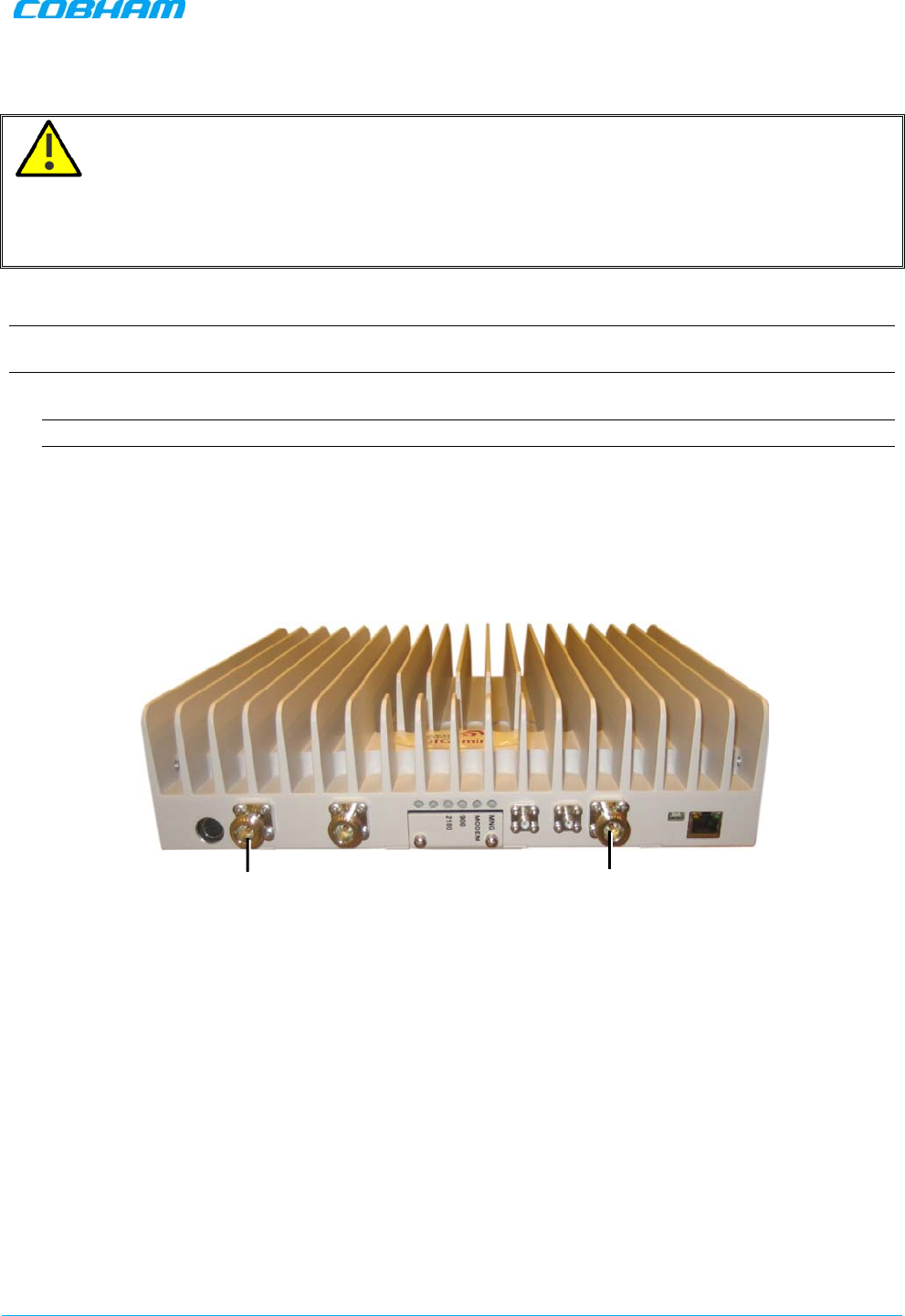
1.6.1 Front Panel Interfaces
The image below shows the unit (the wallmount bracket is not shown).
Figure 1-2: DIGImini Dual-Band Front Panel
The following table provides a description of the front panel connectors.
Port Description
MOBILE Service antenna connections.
BASE Donor antenna connections.
DC Power (12V) Circular, 4-PIN.
RJ 45 Used for setup.
If the support for external modem License file is acquired, the
Ethernet port can also be connected to the network or used to connect to an
external modem.
ATTENTION!! Do not connect to the network unless you have purchased
either the DMCU or the external modem support license file.
*Not in use. Termination is NOT required.
Status LEDs
N/A*
Power
Mobile
N/A*
Base
ETH
RJ45
DIGIMINI AMERICAS REPEATERS
PRODUCT DESCRIPTION AND USER’S MANUAL
Cobham Wireless – Coverage Date: 6-Jul-17 www.cobham.com/wireless
Document number: 00031UM Rev. 6.3 Page |1-5
The following table provides a description of the front panel LED indicators (see 6.2.2 for more info).
LED Description
Band specific
LED
(e.g. 850, 1900, etc) Downlink path status and RSSI indication:
MNG Relevant only if connected to DMCU:
CCD Operation status
MODEM Relevant only if connected to DMCU:
DMCU Modem operation status
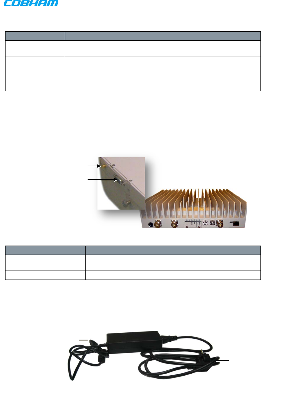
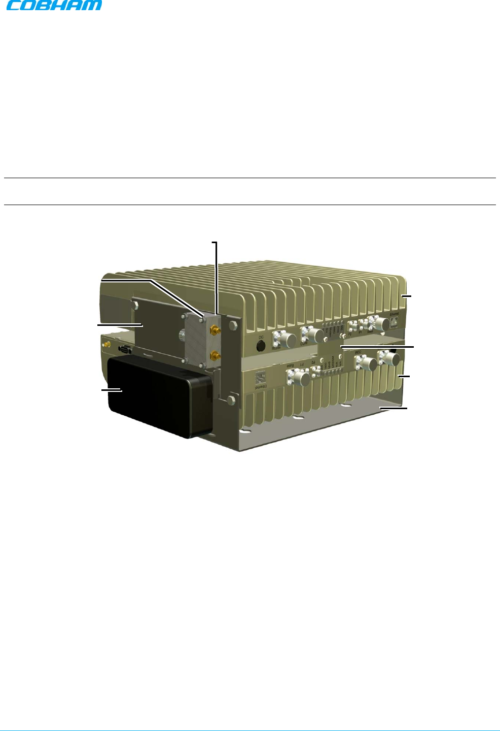
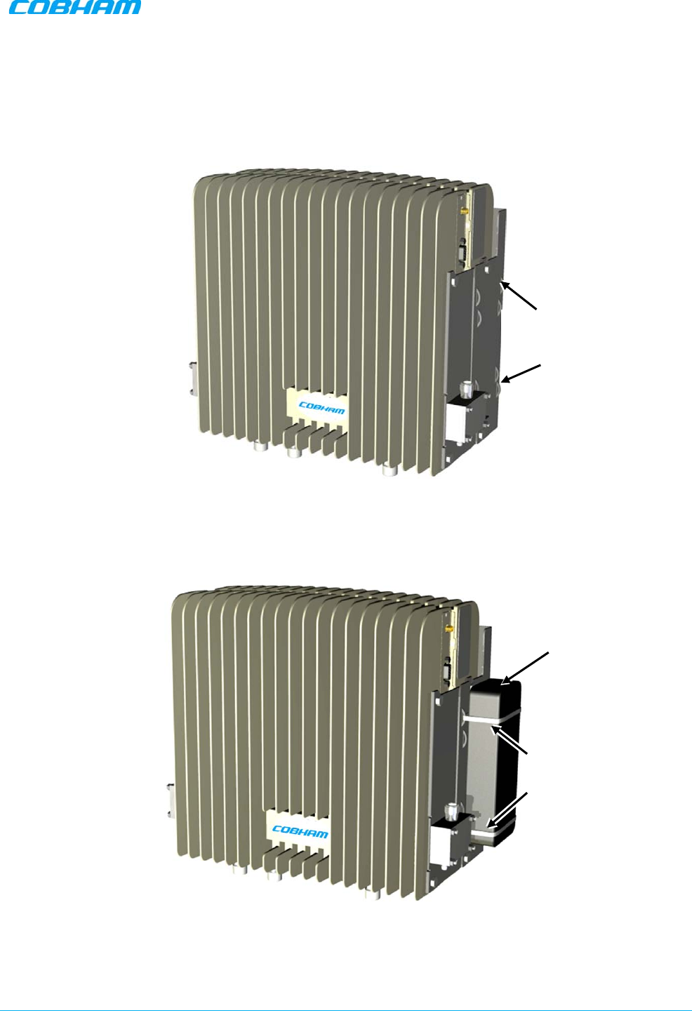
1.6.2 Side Panel Interfaces
The DIGImini side panel supports the DMCU interfaces and the side bolts used for hanging the unit on the
wall bracket. For DMCU interfaces descriptions refer to the DMCU User Manual.
Figure 1-3. DIGImini Side Panel
Side Connector Description
Modem DMCU Modem Antenna connection - relevant for installation with
a DMCU.
RS485 RS485 connection to DMCU option.
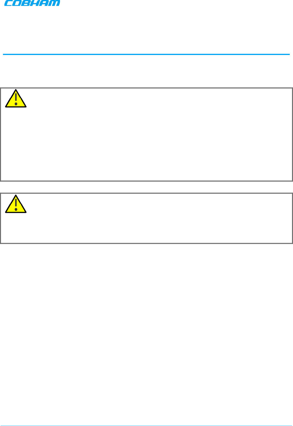
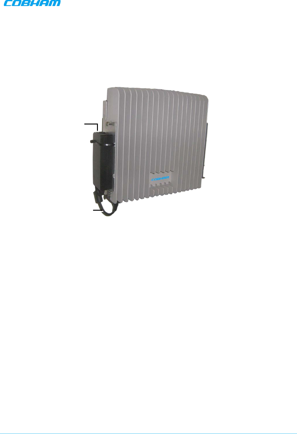
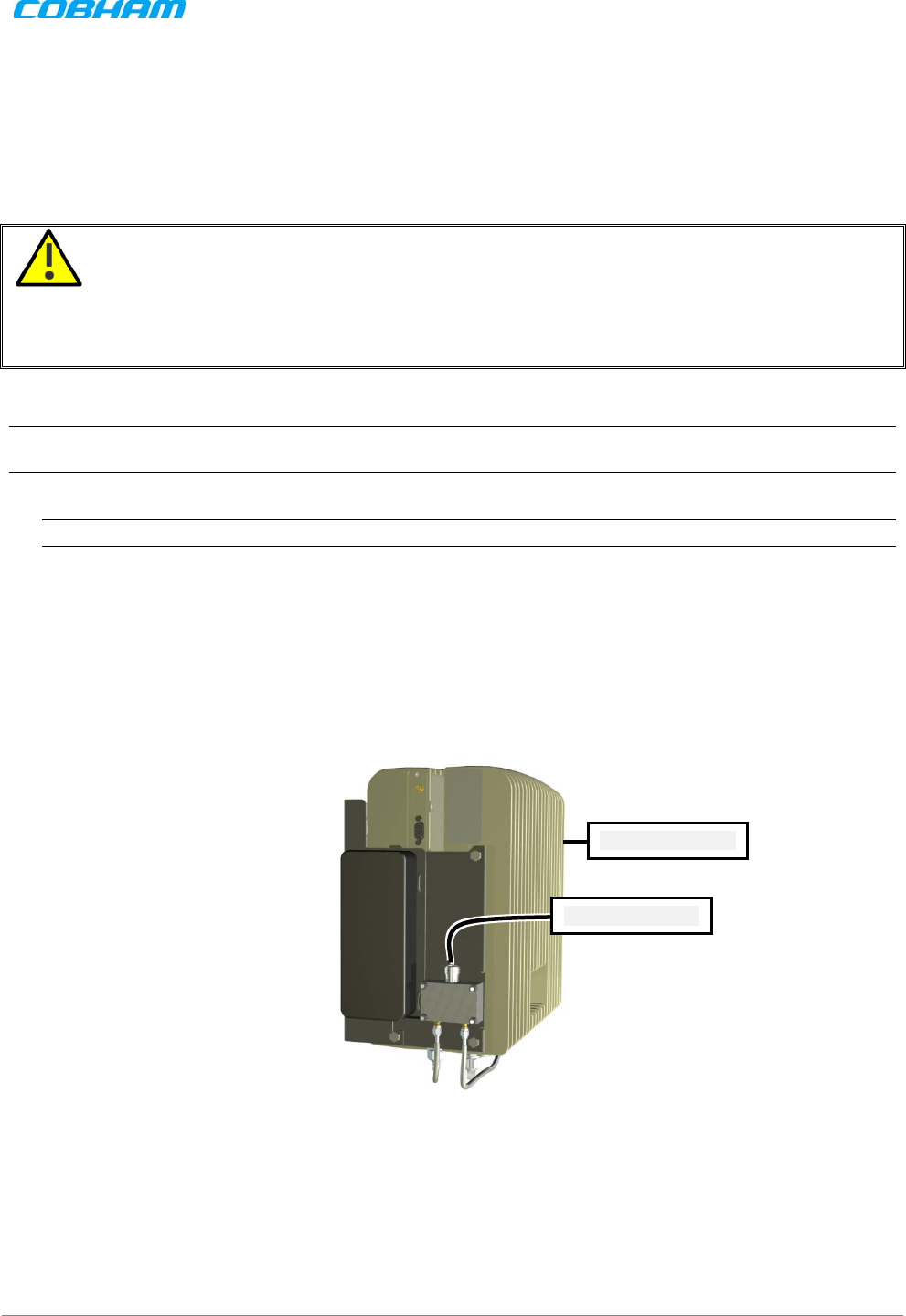
1.6.3 DIGImini Power Supply
The power supply requires assembly only during an upgrade procedure from a dual-band to a triple-band or
quad-band solutions in which two DIGImini units are cascaded. Otherwise, it is preassembled.
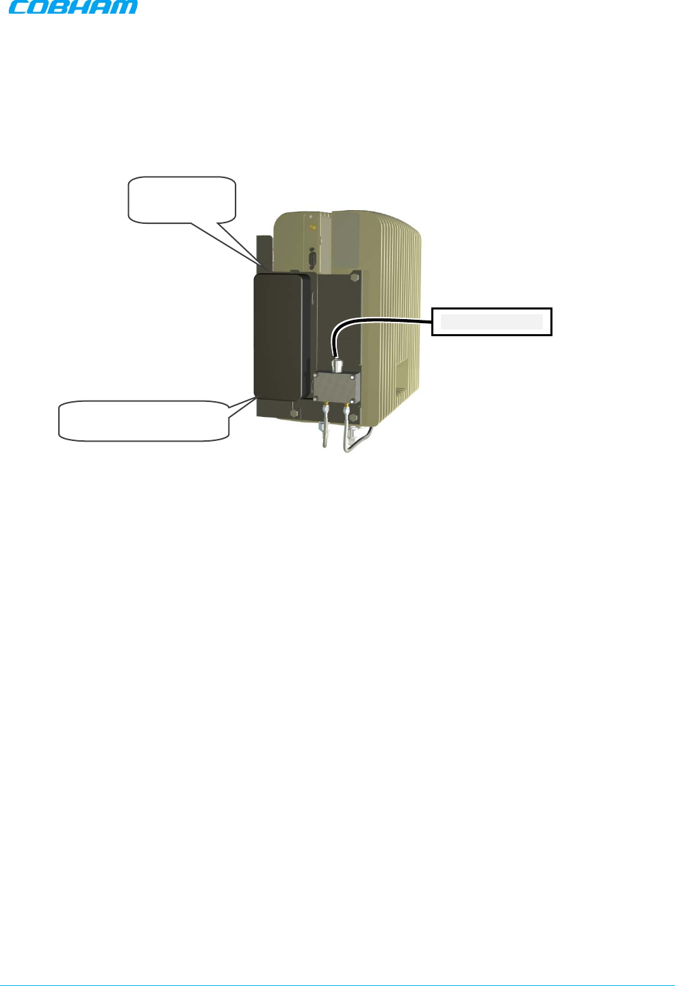
Figure 1-4: Repeater Power Supply
Connect to 110/240
VAC power source
Connect to Front
panel DC power
(12V) connector
DMCU Antenna
connection
DMCU RS485
connection
DIGIMINI AMERICAS REPEATERS
PRODUCT DESCRIPTION AND USER’S MANUAL
Cobham Wireless – Coverage Date: 6-Jul-17 www.cobham.com/wireless
Doc. No.: 00031UM Rev. 6.3 Page | 2-1
2 ANTENNA AND REPEATER INSTALLATION
REQUIREMENTS
This chapter provides information on the specifications of the donor and service antennas suitable for
operation with this repeater, on the installation requirements of the antennas and on the Repeater
installation site and cable requirements.
ATTENTION!!
The DIGImini models described in this manual have been approved by Industry Canada to operate with the
antenna types listed below with the maximum permissible gain and required antenna impedance for each
antenna type indicated. Antenna types not included in this list, having a gain greater than the maximum
gain indicated for that type, are strictly prohibited for use with this device.
Le présent émetteur radio (identifier le dispositif par son numéro de certification ou son numéro de modèle
s'il fait partie du matériel de catégorie I) a été approuvé par Industrie Canada pour fonctionner avec les
types d'antenne énumérés ci-dessous et ayant un gain admissible maximal et l'impédance requise pour
chaque type d'antenne. Les types d'antenne non inclus dans cette liste, ou dont le gain est supérieur au gain
maximal indiqué, sont strictement interdits pour l'exploitation de l'émetteur.
ATTENTION!!
• The installer is held accountable for implementing the rules required for deployment.
• Good engineering practice must be used to avoid interference.
• Output power should be reduced to solve any IMD interference issues.
2.1 Base (Donor) Antenna Requirements
The Base (Donor) antenna is usually installed outdoors and is either a directional antenna such as a Yagi or
a Panel antenna.
2.1.1 Required Antenna Information
You will require the following antenna information
• Antenna type and characteristics
• Height
• Length and type of coaxial cable required for connecting the Donor antenna to the Repeater and the
attenuation.
2.1.2 Donor Antenna specifications
• Maximum antenna gain for outdoor operation: 9dBi.
• Maximum antenna gain for indoor operation 2.2dBi
• Very sharp beam pointed to the BTS.
• Cable and jumper loss is at least 2dB.

DIGIMINI AMERICAS REPEATERS
PRODUCT DESCRIPTION AND USER’S MANUAL
Cobham Wireless – Coverage Date: 6-Jul-17 www.cobham.com/wireless
Document number: 00031UM Rev. 6.3 Page |2-2
2.1.3 Installation Criteria
Installation requirements:
• Select a location for the Donor antenna and verify that there is enough signal strength at that location.
• Install the Donor Antenna at the designated height.
• The antenna should point to the direction of the base station for maximum input power.
• Verify that the antenna is in the base stations line of sight (raise the antenna if necessary).
• Install the donor antenna at a higher level (i.e. floor) than the mobile antenna.
• Must be installed at a minimum distance of 20cm from any personnel within the area.
2.2 Service Antenna Requirements
The Service antenna is installed indoors, where the type of antenna depends on the application.
2.2.1 Required Antenna Information
The following antenna requirements, specifications and site considerations should be met.
• Service area type and size
• Antenna type and characteristics
• Height
• Length and type of coaxial cable required for connecting the antenna to the Repeater and the
attenuation.
2.2.2 Recommended Antennas
• One or a combination of the following antennas can be used: Ceiling Mount Patch antenna, Wall Mount
Patch antenna, Corner Reflector.
• Choose an antenna with high side lobe attenuation which enables maximum isolation from the service/
mobile antenna.
• Maximum antenna gain for indoor operation 2.2dBi
• Cable and jumper loss is at least 2dB.
2.2.3 Service Antenna Installation Criteria
Determine the antenna installation configuration, according to the transmission requirements and the
installation site conditions.
Installation requirements:
• An indoor antenna should be installed at a convenient location. It should be free of metallic obstruction.
• Install the Service Antenna at the designated height and tune it roughly toward the Service coverage
area.
• Installation of this antenna must provide a minimum separation distance of 20cm from any personnel
within the area.

DIGIMINI AMERICAS REPEATERS
PRODUCT DESCRIPTION AND USER’S MANUAL
Cobham Wireless – Coverage Date: 6-Jul-17 www.cobham.com/wireless
Document number: 00031UM Rev. 6.3 Page |2-3
2.3 Repeater Pre-Installation Requirements
2.3.1 Safety Guidelines
Before installing the Repeater, review the following safety information:
• Follow all local safety regulations when installing the Repeater.
• Only qualified personnel are authorized to install and maintain the Repeater.
• Ground the Repeater with the grounding bolt located on the external lower side of the Repeater).
• Do not use the grounding bolt to connect external devices.
• Follow Electro-Static Discharge (ESD) precautions.
• Use low loss cables to connect the antennas to the Repeater.
2.3.2 Required BTS Information
Required BTS Information
• BTS channels
• BTS output power per channel
• BTS antenna gain
• BTS antenna height
• Distance from Repeater site to BTS
2.3.3 Criteria for Repeater Installation Location
The following criteria should be considered when selecting the Repeater installation site location:
• Application type
• General surroundings
• Available installation
• Install the Repeater in a shielded, ventilated, and easy-to-reach area.
• Verify that there is a minimum of a 50 cm (20”) radius of space around the Repeater, enabling easy
access to the repeater for maintenance and on-site inspection.
• Distance from antenna site - It is recommended that the installation location be as close as possible to
the antenna site in order to maintain the cable loss to a minimum.
• The Repeater is convection cooled so airflow and alternation should be possible.
• Follow Electro-Static Discharge (ESD) precautions.
• Install the Repeater close to the service area to monitor the output power.
• Use low loss cables to connect the antennas to the Repeater.
2.3.4 RF Cable Installation Guidelines
Required:
• For all coaxial connections to/from the Repeater - high performance, flexible, low loss 50 ohm coaxial
communications cable.
• All cables shall be weather-resistant type.
• Cable length - determined by the Repeater installation plan. When calculating the cable length, take into
account excess cable slack so as not to limit the insertion paths.

DIGIMINI AMERICAS REPEATERS
PRODUCT DESCRIPTION AND USER’S MANUAL
Cobham Wireless – Coverage Date: 6-Jul-17 www.cobham.com/wireless
Doc. No.: 00031UM Rev. 6.3 Page | 3-1
3 SINGLE UNIT REPEATER INSTALLATION
This installation is relevant for a single DIGImini unit supporting either a single-band or a dual-band.
3.1 Overview
NOTE: The Donor and Mobile antennas can be positioned and installed (
without being connected to the
Repeater
) at any time either
before
or after
mounting
and grounding the Repeater.
1. Unpack the Repeater kit.
2. Mount the Bracket on the wall, hang the Repeater and Power Supply on the bracket (do not connect
power).
3. Perform the required isolation and link tests.
4. Connect the antennas.
5. Power-on the Repeater.
6. If a DMCU is available, mount the unit (adjacent to the Repeater, on the wall and connect to the
Repeater according to the DMCU User Manual).
3.2 Required Tools and Materials
The following is required in order to install the Repeater:
• Standard professional tool box
• A computer (i.e. laptop for running the setup)
DIGIMINI AMERICAS REPEATERS
PRODUCT DESCRIPTION AND USER’S MANUAL
Cobham Wireless – Coverage Date: 6-Jul-17 www.cobham.com/wireless
Document number: 00031UM Rev. 6.3 Page |3-2
3.3 DIGImini Single Unit Kit
Upon receiving the Repeater, perform the following:
1. Examine the shipping container for damage before unpacking the unit.
2. Perform a visual inspection to reveal any physical damage to the equipment.
3. Verify that all of the equipment (listed below) is included. Otherwise contact Cobham Wireless.
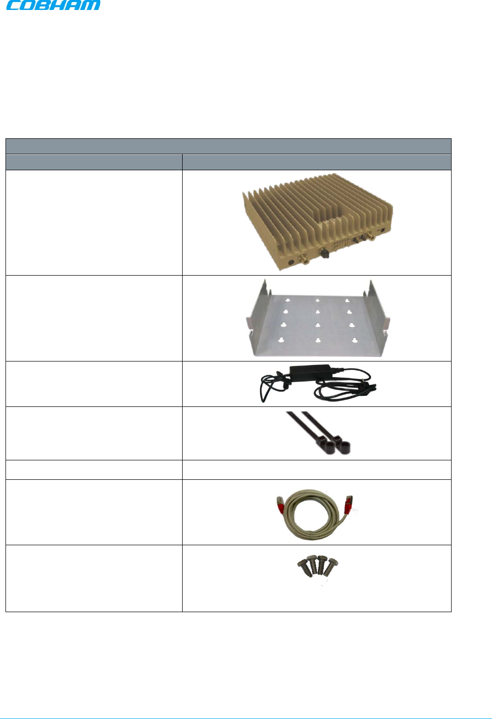
DIGImini Repeater Kit
Description Image
DIGImini Repeater
Wallmount Bracket
Repeater Power Supply (12V)
2 x Ties for securing power supply
USB with documentation
Ethernet Cross-cable
4 x Repeater Mounting Bolts
DIGIMINI AMERICAS REPEATERS
PRODUCT DESCRIPTION AND USER’S MANUAL
Cobham Wireless – Coverage Date: 6-Jul-17 www.cobham.com/wireless
Document number: 00031UM Rev. 6.3 Page |3-3
3.4 Mounting the Repeater
Choose the location of the Repeater on the wall according to the following criteria:
• The location should be at normal eye level height, above ground.
• Be sure to allow easy access to the Repeater for maintenance and on-site inspection.
WARNING!!! The Repeater must always be installed vertically and top-down, to allow free-flow of
cooling air. Horizontal installation on a bench for prolonged period of time may cause damage to the
Repeater due to over-heating
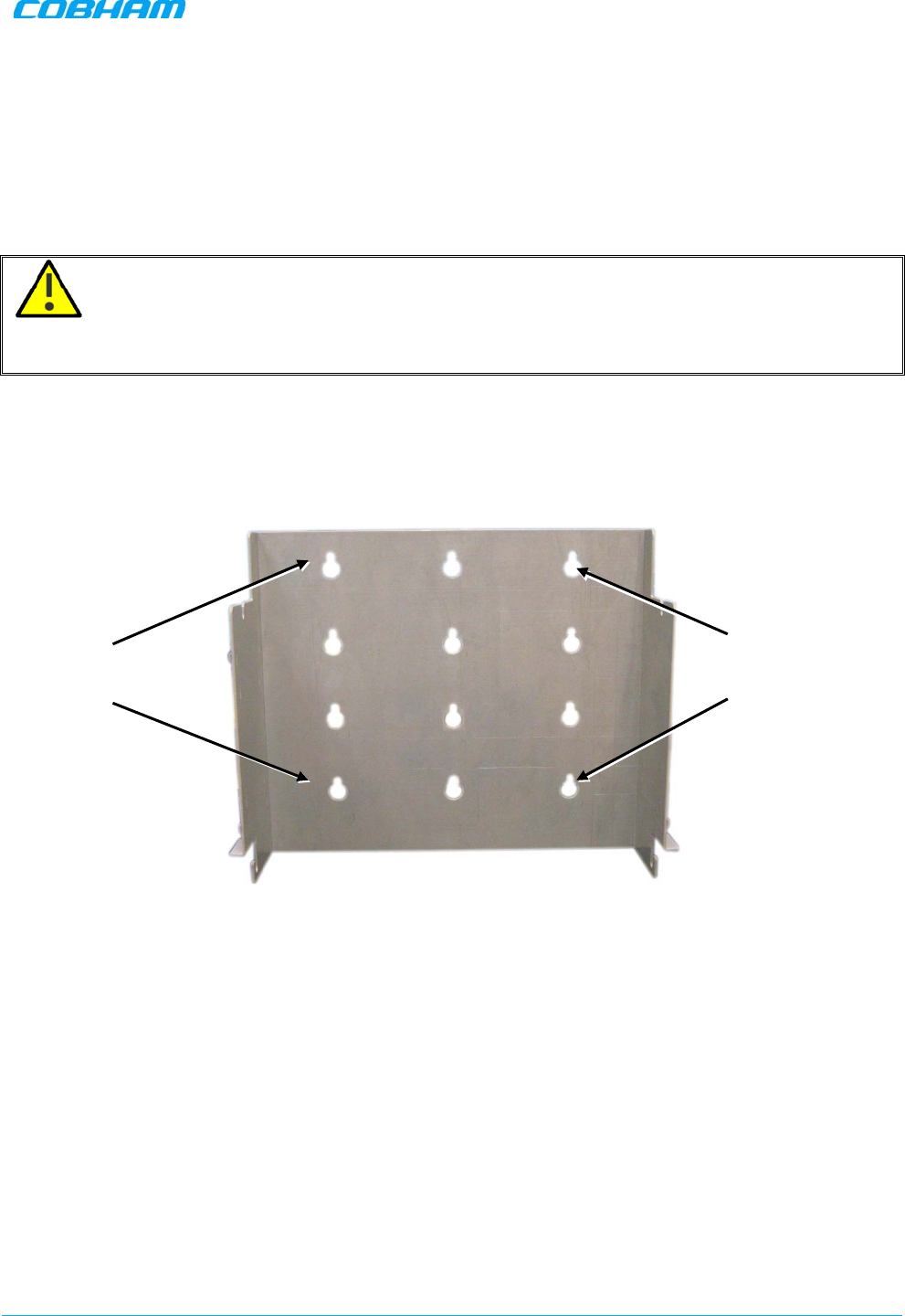
To mount the Repeater on the wall
1. Using the bracket for reference to the bolt locations, insert the appropriate bolts (not supplied) on the
wall, according to the type of wall.
2. Hang the bracket on the wall.
Figure 3-1. Mounting the Bracket on the Wall
Location of
assembly holes
Location of
assembly holes
DIGIMINI AMERICAS REPEATERS
PRODUCT DESCRIPTION AND USER’S MANUAL
Cobham Wireless – Coverage Date: 6-Jul-17 www.cobham.com/wireless
Document number: 00031UM Rev. 6.3 Page |3-4
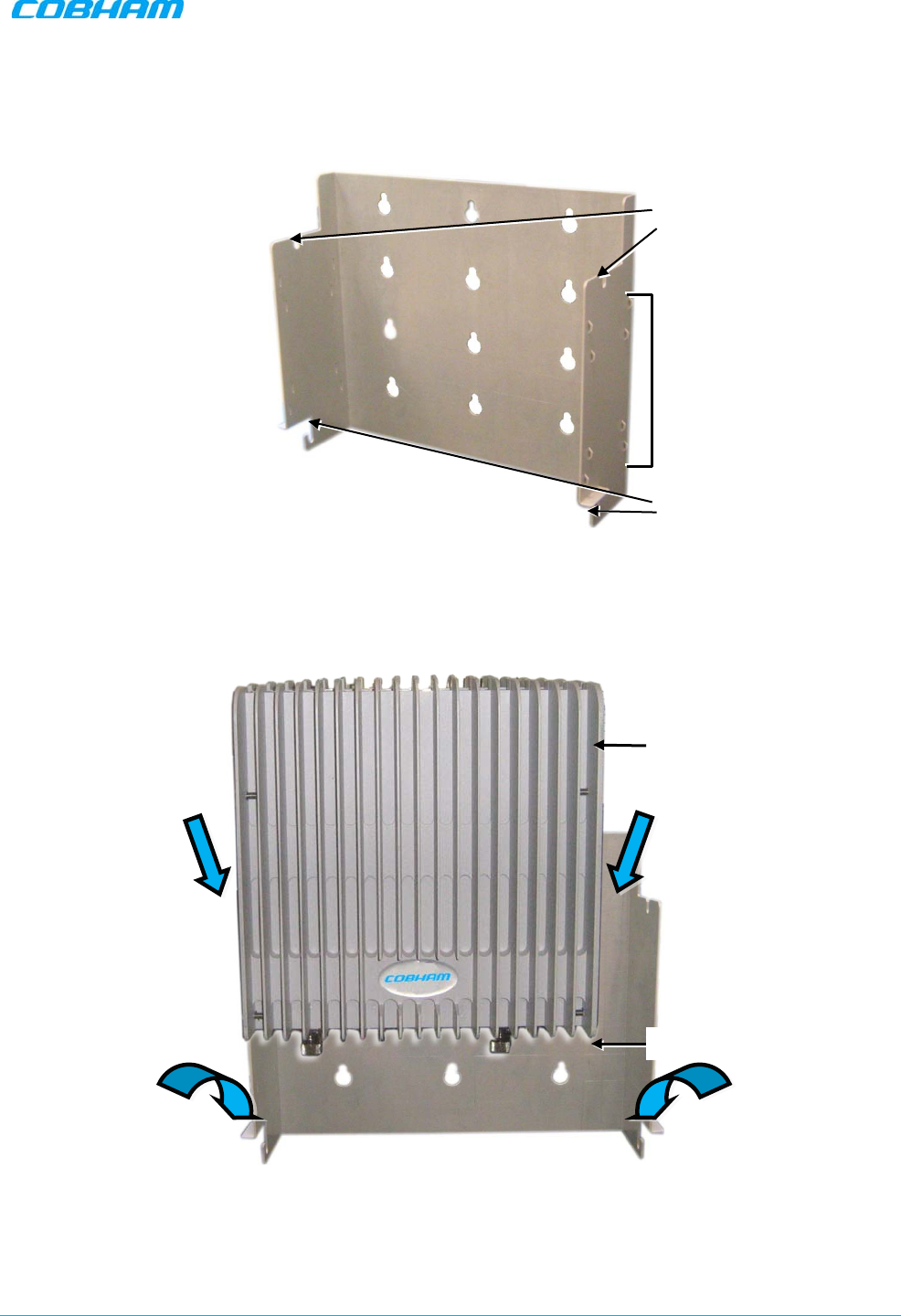
The bracket provides two main capabilites:
• Four slots (two bottom and two top) on which to hang the Repeater.
• A step and loops on each side of the bracket for securing the power supply (on any of the sides).
Figure 3-2. Bracket description
3. Hang the Repeater on the Bracket, ridges facing outwards as illustrated below. Use repeater (four) SIDE
screws to hang the Repeater securely on the bracket side slots.
Figure 3-3. DIGImini to Bracket Mounting
Connectors down
Top slots for
hanging
Bottom slots for
hanging
Mounting and
securing P.S.
(on either side)
Heatsink ridges facing
Outward
Fit two BOTTOM
Repeater bolts on
bracket slots and lift UP
to slide two TOP screws
into top slots
DIGIMINI AMERICAS REPEATERS
PRODUCT DESCRIPTION AND USER’S MANUAL
Cobham Wireless – Coverage Date: 6-Jul-17 www.cobham.com/wireless
Document number: 00031UM Rev. 6.3 Page |3-5
4. Verify that the Repeater is firmly mounted and
tighten
the Repeater bolts so it is secured to the wall
mount bracket.
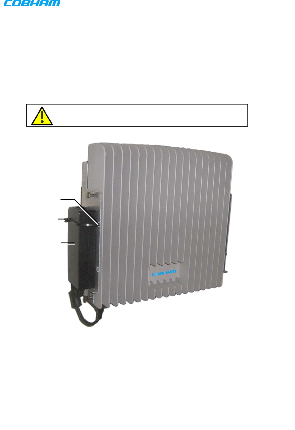
5. To mount the Repeater Power Supply:
• Pass two ties through the loops at the side of the bracket.
• Position the PS on either side of the bracket, firmly on the step and secure the power supply to the
bracket using the ties.
• Trim the ties
WARNING!!! Do NOT connect power at this point.
Figure 3-4. Mounting Power Supply
3.5 Before Connecting the Antennas or Power
Before connecting the antennas or power perform the following procedures described in this section:
• Verify isolation between the donor and mobile antennas
• Verify link between the BTS and the Repeater
1. Pass ties
through loops
2. Position P.S.
firmly on step
and
secure with ties
3. Trim ties
DIGIMINI AMERICAS REPEATERS
PRODUCT DESCRIPTION AND USER’S MANUAL
Cobham Wireless – Coverage Date: 6-Jul-17 www.cobham.com/wireless
Document number: 00031UM Rev. 6.3 Page |3-6
3.5.1 Verifying Donor and Service Antennas Isolation
CAUTION!! The isolation between the Base/Donor and Mobile/Service antennas is critical. Lower
isolation can lead to high in-band ripple, oscillations and low signal quality.
The isolation between the Base/Donor and Mobile/Service antennas is critical.
• For proper operation of the Repeater, it is recommended that the isolation between the Donor and
Service antennas be at least 10dB higher than the Repeaters set gain.
• Insure proper vertical or horizontal distance separation between Donor and Service antennas
NOTE: Lower isolation can lead to high in-band ripple, oscillations and low signal quality.
To measure the isolation, proceed as follows:
1. Inject a known signal from a signal generator into one antenna (preferably the Donor antenna).
2. Measure the coupled output from the Service antenna, using the Spectrum analyzer and LNA if
applicable.
3. Perform this procedure across the frequency range of both the Uplink and Downlink bands.
4. Register the lower result for system operation.
3.5.2 Verifying Link between the BTS and the Repeater
Before connecting the antennas or powering up the Repeater, verifying the Link between the BTS and the
Repeater
This test checks the signal strength from the BTS antenna to the Repeater.
WARNING!! Perform this procedure before connecting the antennas to the Repeater or powering
on the Repeater. The Repeater should not be operated prior to the verification of the operating parameter in
its installation environment.
Proceed as follows:
1. Using a Spectrum analyzer, measure the received signal from BTS at the Donor antenna port near the
Repeater.
2. Adjust the Donor antenna direction to receive the maximum signal strength.
3. Compare the received signal strength with the calculated signal strength from the design phase.
In case of discrepancy, check for one of the following:
• Antenna out of direction
• Antenna tuned to side lobe instead of main lobe
• Antenna connector or antenna cable faulty
• Line-of-sight problem (obstruction), etc.
4. Register the signal strength of the downlink channel for the system operation phase.
DIGIMINI AMERICAS REPEATERS
PRODUCT DESCRIPTION AND USER’S MANUAL
Cobham Wireless – Coverage Date: 6-Jul-17 www.cobham.com/wireless
Document number: 00031UM Rev. 6.3 Page |3-7
3.6 Antenna Connections
CAUTION!!
• Do not connect the antenna cables to the Repeater before verifying the installation parameters.
• Do not power-up the Repeater without either the antennas being connected or the antenna connections
terminated with dummy loads. To connect the antennas to the Repeater
To connect the antennas to the Repeater
NOTE: If the coaxial cables are NOT weather-resistant type, wrap the exterior coaxial cables with insulation
and holding tape (Type 3M Rubber splicing tape) for environmental protection and to ensure longer lifetime.
1. Install the antenna cables along their path to the Repeater, and connect them to the Antennas.
NOTE: Be sure to use low loss cables.
2. Connect the Donor antenna to the Repeater BASE port. (Donor antenna specifications and installation
criteria are described in section 2.1).
3. Connect the Service antenna to the Repeater MOBILE port. (Mobile antenna specifications and
installation criteria are described in Chapter 2).
4. Verify all RF connectors are tightened and the cables and antennas are secured.
Figure 3-5. Antenna Connections
Mobile
Base
DIGIMINI AMERICAS REPEATERS
PRODUCT DESCRIPTION AND USER’S MANUAL
Cobham Wireless – Coverage Date: 6-Jul-17 www.cobham.com/wireless
Document number: 00031UM Rev. 6.3 Page |3-8
3.7 Power Up
To power up
Connect the Repeater P.S. to the AC power outlet and to the Repeater DC connector.
Figure 3-6. Powering Up
3.8 What Next?
• Installations
without
DIGImini Control Unit (DMCU) – continue to Chapter 5 - SETUP AND
CONFIGURATION.
• Installations
with
DMCU – refer to the DMCU User Manual.
Connect to
110/240
VAC
Connect to repeater
power connector

DIGIMINI AMERICAS REPEATERS
PRODUCT DESCRIPTION AND USER’S MANUAL
Cobham Wireless – Coverage Date: 6-Jul-17 www.cobham.com/wireless
Doc. No.: 00031UM Rev. 6.3 Page | 4-1
4 QUAD-BAND REPEATER INSTALLATION
This procedure describes how to assemble and install the DIGImini dual unit assembly supporting up to four
bands (quad-band). The assembly consists of two repeaters.
If your installation includes a DMCU, only one
DMCU is required for the complete quad-band assembly (two repeaters).
4.1 Overview
NOTE: The Donor and Mobile antennas can be positioned and installed (without being connected to a
Repeater) at any time either
before
or after
mounting
and grounding the Repeater.
1. Unpack the Repeater Tri/Quad-band kit.
2. Mount the wallmount bracket on the wall
3. Assemble the RF Combiners and Combiner Spacers onto the Quad-band brackets.
4. Using the supplied brackets, position the repeaters back to back on a flat surface and interconnect the
required interfaces as described in section 4.5.3.
5. Pick-up the two-Repeater assembly and hang on the mounted wall bracket.
6. Mount the Power Supplies on the wall bracket (do not connect power).
7. Perform the required isolation and link tests.
8. Connect the antennas.
9. Power-on the Repeater.
10. For installations with a DMCU, mount the unit and refer to the DIGImini Single/Dual Band user manual
for detailed instructions.
DIGIMINI AMERICAS REPEATERS
PRODUCT DESCRIPTION AND USER’S MANUAL
Cobham Wireless – Coverage Date: 6-Jul-17 www.cobham.com/wireless
Document number: 00031UM Rev. 6.3 Page |4-2
4.2 View of the Dual Unit Installation
The following figure illustrates the Quad-band DIGI-mini assembly.
The following figure illustrates the Triple/Quad-band DIGI-mini assembly.
Note the following:
• The Tri/Quad-band assembly supports
two RF combiners
, mounted on each side bracket.
• The front panel LED interfaces are interconnected and covered with a common tab.
NOTE: Illustration below shows a bottom view of the mounted Quad-band assembly (connectors face down
when the assembly is wall mounted).
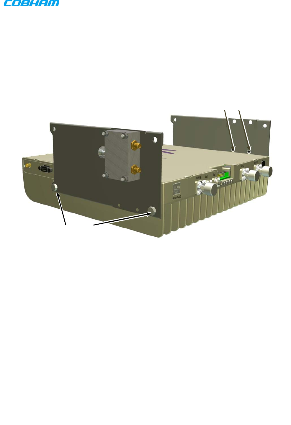
Figure 4-1: Cascaded DIGImini Tri/Quad-band
4.3 Required Tools and Materials
The following is required in order to install the Repeater:
• Standard professional tool box
• A computer (i.e. laptop for running the setup) – refer to the single/dual band user manual for setup and
commissioning procedure.
DIGImini Unit
Combiner- one on
each side
Power Supply –
one on each side
Cascading
Bracket –
on
each side
DIGImini Unit
Common
indicators
Wall bracket
Spacer between
Combiner and bracket
DIGIMINI AMERICAS REPEATERS
PRODUCT DESCRIPTION AND USER’S MANUAL
Cobham Wireless – Coverage Date: 6-Jul-17 www.cobham.com/wireless
Document number: 00031UM Rev. 6.3 Page |4-3
4.4 DIGImini Tri/Quad-band Kit
The Quad-Band Kit contents are packaged in a single box, consisting of
three layers
of items as shown and
additional items (screws, ties, etc.) that may be located in any of the layers
.
The two mini-repeater units are supplied in a separate package.
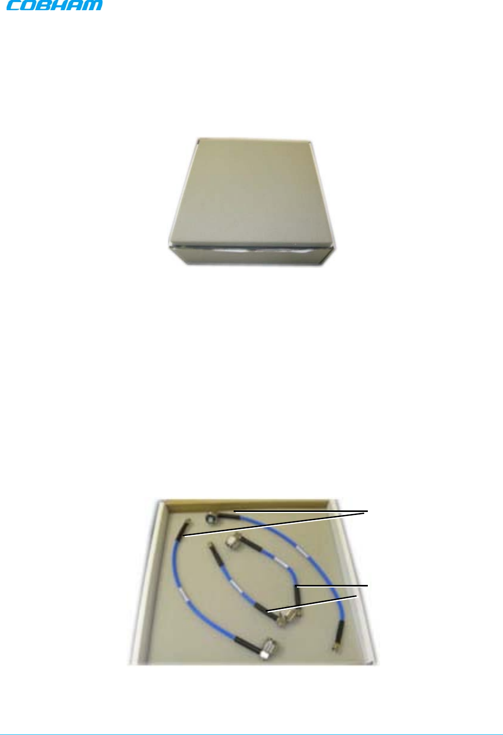
Figure 4-2. Quad-Band Kit Package
Upon receiving the kit, perform the following:
1. Examine the shipping container for damage before unpacking the unit.
2. Perform a visual inspection to reveal any physical damage to the items.
3. Verify that all of the items are included in the relevant layer as described. Otherwise contact Cobham
Wireless.
4.4.1 Top Layer Items
Figure 4-3. Quad-Band Kit – Top Layer
X2 Long Coupling
SMA jumper cables
X2 Short Coupling
SMA jumper cables
DIGIMINI AMERICAS REPEATERS
PRODUCT DESCRIPTION AND USER’S MANUAL
Cobham Wireless – Coverage Date: 6-Jul-17 www.cobham.com/wireless
Document number: 00031UM Rev. 6.3 Page |4-4
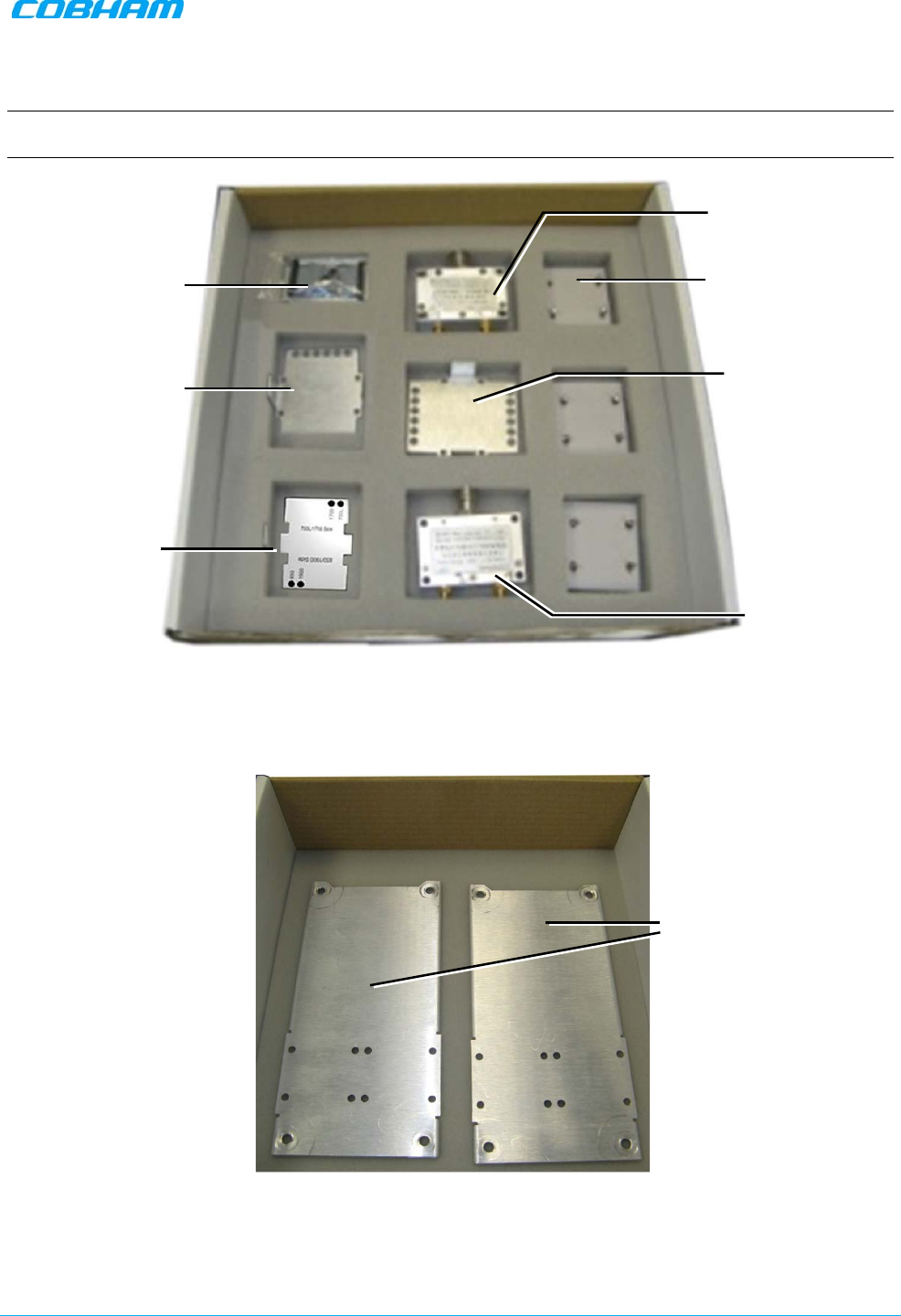
4.4.2 Middle layer Items
NOTE: References to Type I and Type II DIGImini models are explained in the following sections when the
relevant instructions are given.
Figure 4-4. Quad-Band Kit -Middle Layer items
4.4.3 Bottom Layer Items
Figure 4-5. Quad-Band Kit-Bottom Layer Items
Flat Cable +
Combiner Spacers
X1 Quad-
band
plate for Type I +
Type II units
Labels for Type 2
only and
Type 1 +
Type 2
x3 Quad-band plate
for two
Type I units
RF Combiner
RF Combiner
x1 Quad-band plate
for Type II only
2 x Expansion,
Side Brackets
DIGIMINI AMERICAS REPEATERS
PRODUCT DESCRIPTION AND USER’S MANUAL
Cobham Wireless – Coverage Date: 6-Jul-17 www.cobham.com/wireless
Document number: 00031UM Rev. 6.3 Page |4-5
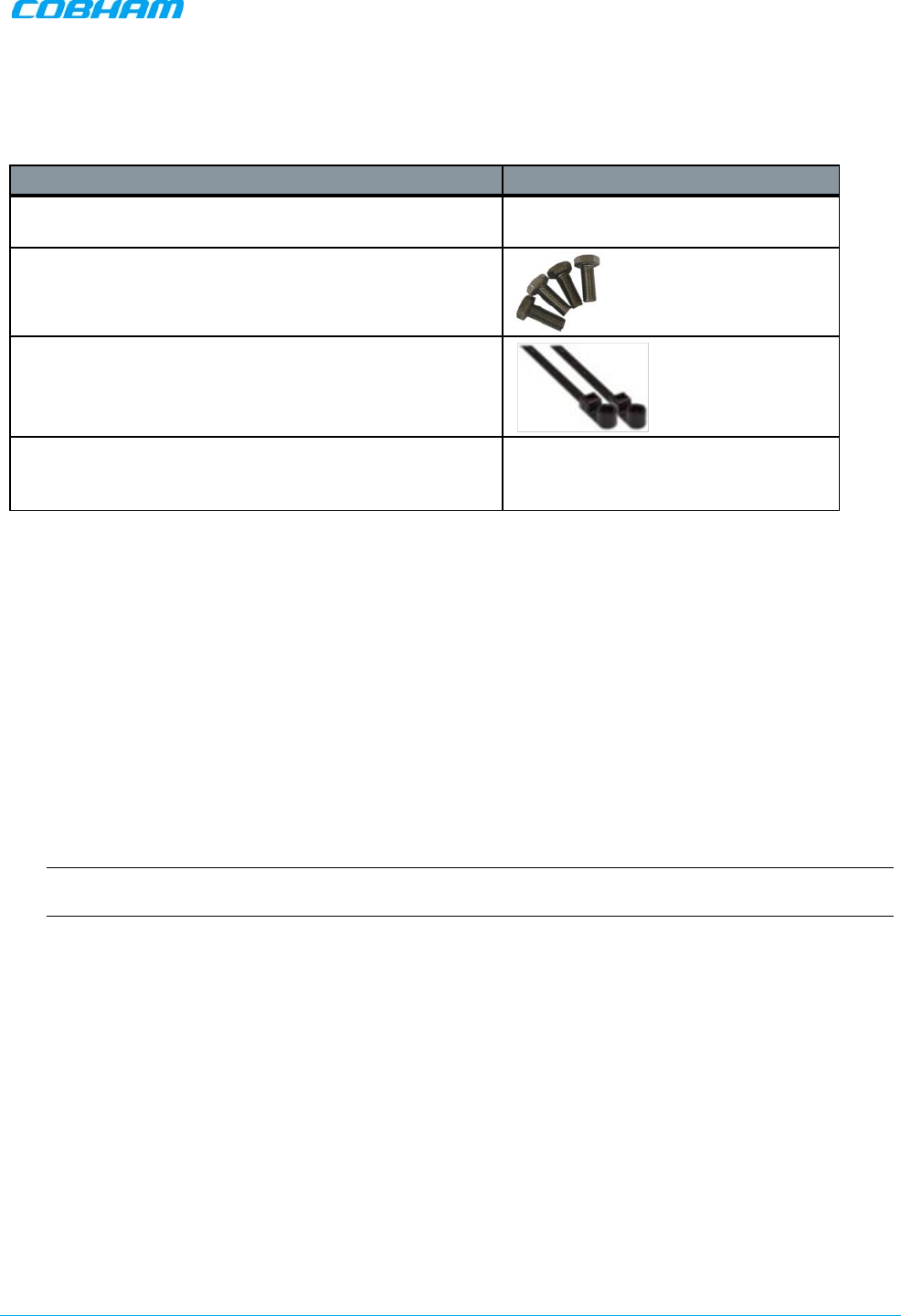
4.4.4 Additional Items
The following additional items are included in the accessory kit and may be packaged in any one of the
layers.
Item Image
8 x Bolts, 8 x Nuts – for Combiner to Spacer to Bracket
assembly
4 x Repeater Mounting Bolts
Ties - used for securing
power supply (only x2 are
required for each power supply –
extra ties may be
included in the kit)
4 x Screws (In use only with the flat cable cover plate of
new chassis (any Type 2 combination), to connect the
plate)
4.5 Upgrading to a Quad-Band System
4.5.1 Assemble the DIGImini Units
The upgrading procedure is partially performed on a flat surface.
1. To upgrade an existing DIGImini Dual band installation:
• Remove power from the currently mounted DIGImini.
• Disconnect all antenna, communication and control cables.
• Loosen the side screws and remove the Repeater –
leaving the wallmount bracket on the wall
.
• Continue with step 3.
2. For a complete Quad-band installation (no existing unit):
NOTE: If holes are to be drilled, use the bracket to mark the hole locations prior to the following
assembly procedure.
• Follow the (wallmount) bracket mounting instructions in 3.4 - Mounting the Repeater.
• Continue to following Step 3.
DIGIMINI AMERICAS REPEATERS
PRODUCT DESCRIPTION AND USER’S MANUAL
Cobham Wireless – Coverage Date: 6-Jul-17 www.cobham.com/wireless
Document number: 00031UM Rev. 6.3 Page |4-6
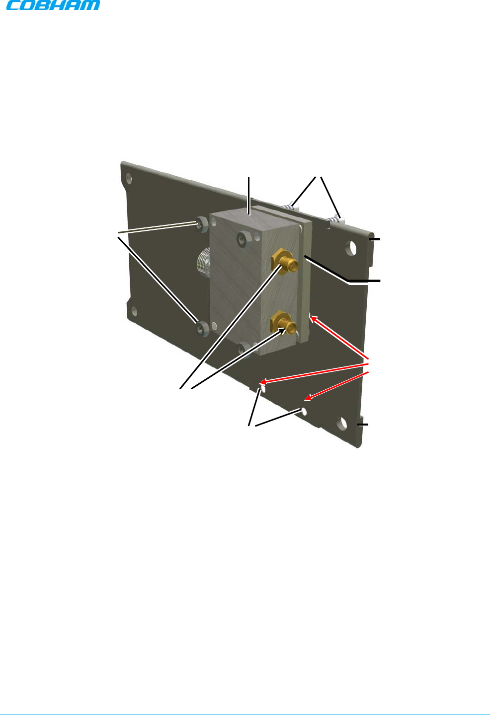
3. If not already assembled:
Assemble each Combiner and Spacer to a Bracket – using the supplied bolts and nuts for
each
assembly. Note DIRECTION of the bracket and that LEFT side is assembled DIFFERENTLY than RIGHT
side.
• Left bracket – assembled on two TOP holes (and center holes) as shown below.
• Right bracket – assembled on two BOTTOM holes (and center holes)
Figure 4-6. Left bracket - Combiner and Spacer Secured to Side Cascading Bracket
X2 connectors
facing this direction
Side Bracket
X2 holes facing
this direction
X4 bolts
Spacer
X4 Nuts
Bracket edge folding over –
AWAY from combiner
Assemble RIGHT side
combiner on these holes
Combiner
DIGIMINI AMERICAS REPEATERS
PRODUCT DESCRIPTION AND USER’S MANUAL
Cobham Wireless – Coverage Date: 6-Jul-17 www.cobham.com/wireless
Document number: 00031UM Rev. 6.3 Page |4-7
4. Assemble Side Brackets on bottom Repeater:
• Place one of the Repeaters on a flat surface – ridges facing down. This will be the bottom
repeater.
• Noting orientation -
loosely
assemble the side plate brackets on both sides of the bottom
repeater.
Figure 4-7. Assemble Side Brackets on Bottom Repeater
Close Loosely on each
side –
but enough to
hold
when assembly is
picked up
Assemble RIGHT side
combiner on these h
oles
and bottom holes
DIGIMINI AMERICAS REPEATERS
PRODUCT DESCRIPTION AND USER’S MANUAL
Cobham Wireless – Coverage Date: 6-Jul-17 www.cobham.com/wireless
Document number: 00031UM Rev. 6.3 Page |4-8
5. Assemble top Repeater:
• Place second repeater back-to-back (flat surfaces together) on bottom repeater.
• Align the top repeater holes with the top side bracket holes and tightly secure. (You may
need to place your hand between the two repeaters in order to maintain the appropriate separation
between the repeaters, allowing the alignment of the bracket holes to the repeaters.)
Figure 4-8. Assemble Top Repeater
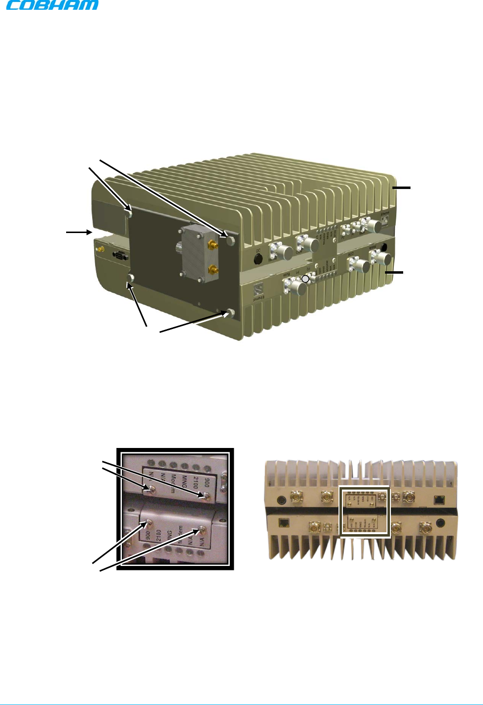
6. Remove the LED plates of BOTH Repeaters and set them aside.
Figure 4-9. Removing Dedicated Tabs
Loosely
secured
Unscrew and
remove plates
Unscrew and
remove plates
Repeater
Repeater
Space
Tightly secure
(do the same for other
bracket on other side)
DIGIMINI AMERICAS REPEATERS
PRODUCT DESCRIPTION AND USER’S MANUAL
Cobham Wireless – Coverage Date: 6-Jul-17 www.cobham.com/wireless
Document number: 00031UM Rev. 6.3 Page |4-9
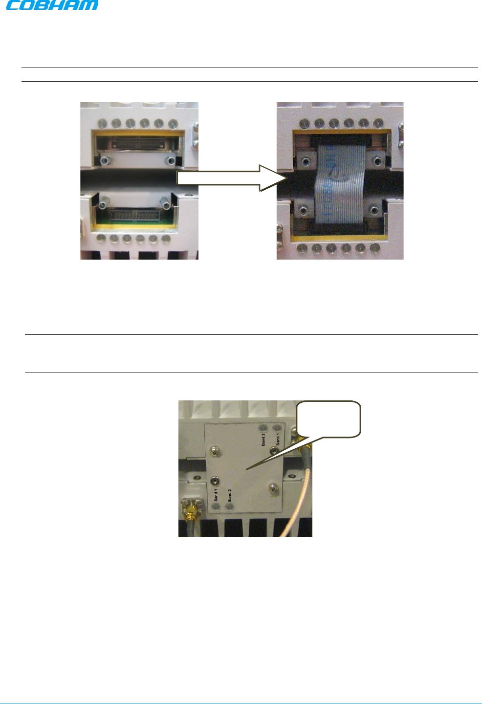
7. Carefully, connect the supplied flat cable between the two connectors as shown below. Verify that
the flat-cable is securely connected.
NOTE: Handle Flat Cable with care when connecting.
Figure 4-10. Interconnecting Flat cable
8. Referring to the following sections, choose the appropriate COVER PLATE and LABEL according to the
type of unit combination that comprises the quad-band assembly section 4.5.2.
9. Cover the flat-cable with the appropriate Flat Cable Cover Plate and secure using the four screws.
NOTE: All labels refer to Band-1 and Band-2. The band frequencies for each repeater are located on
a sticker on the SIDE of the repeater. (e.g for DIGImini 900/2100, “Band 1” is 900 and “Band 2” is
2100).
Figure 4-11. Assembling Interconnecting Cover Plate
Plate covering
flat cable
DIGIMINI AMERICAS REPEATERS
PRODUCT DESCRIPTION AND USER’S MANUAL
Cobham Wireless – Coverage Date: 6-Jul-17 www.cobham.com/wireless
Document number: 00031UM Rev. 6.3 Page |4-10
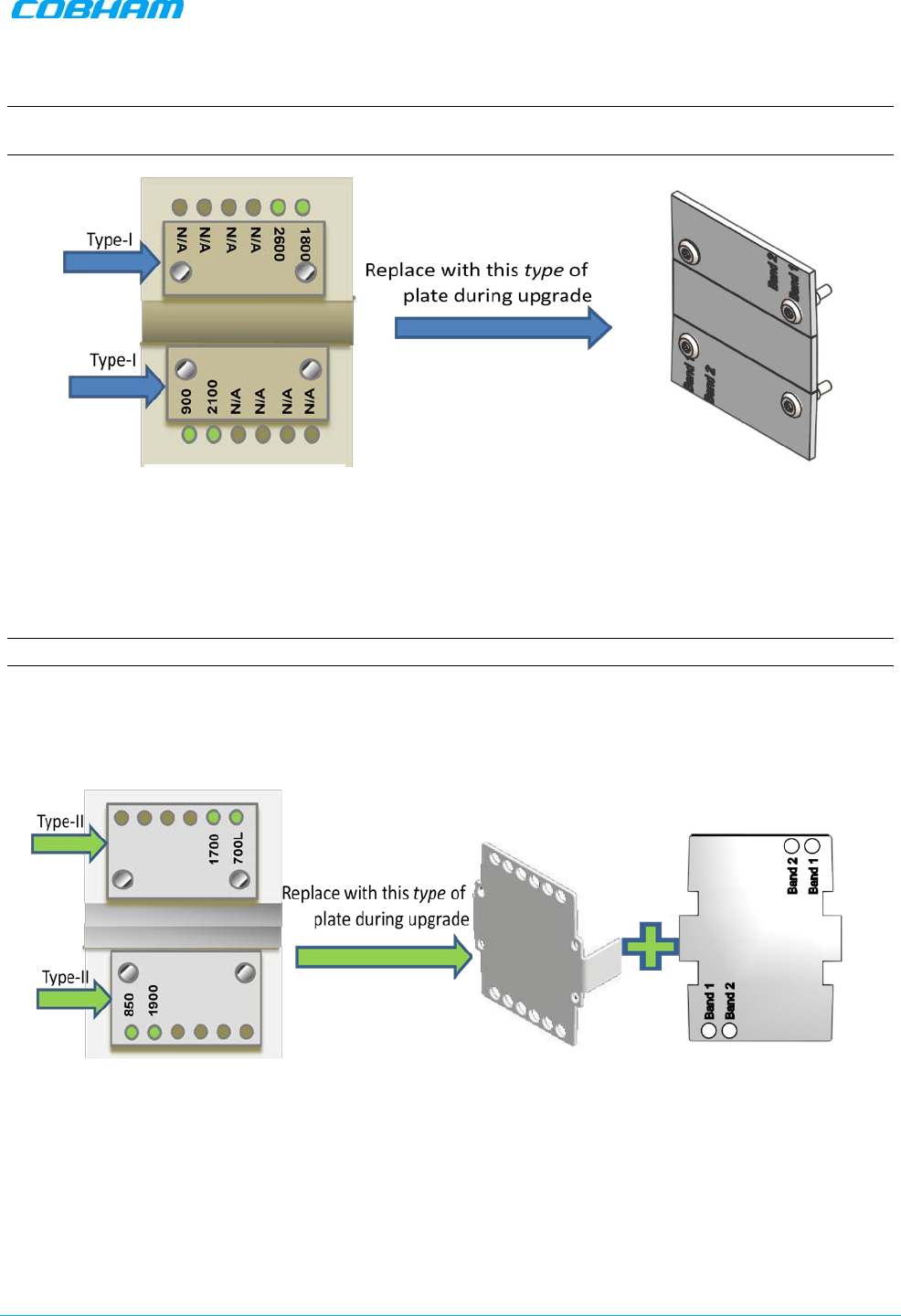
4.5.2 Choosing the Appropriate Plate
Plates and labels are selected according to the type of repeater combinations in the quad-band assembly;
there are type types of repeaters configurations: Type-I and Type-II.
4.5.2.1 Type-I and Type-II Configuration
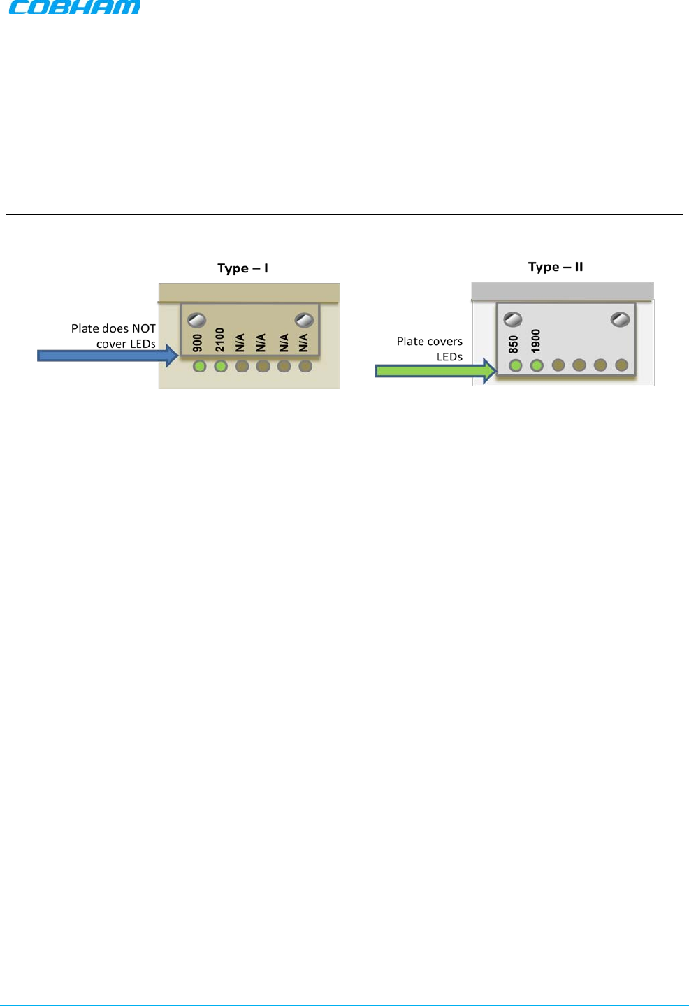
Criteria for Type-I and Type-II units is given below; basically it is determined by
how much the plate covers
the LEDs.
NOTE: For all Type-II units - assemble the PLATE and LABEL (Type-I plate is already labelled).
Figure 4-12.Examples of Type-1 and Type-2 Unit Plates
Three different Quad-Band plate types are provided for the following quad-band combinations:
• Both units in quad-band are Type I
• Both units in quad-band are Type II
• One of each Type (Type I + Type II)
NOTE: The band frequencies represented by Band-1 and Band-2 are located at the side of the repeater.
(e.g for DIGImini 900/2100, “Band 1” is 900 and “Band 2” is 2100).
DIGIMINI AMERICAS REPEATERS
PRODUCT DESCRIPTION AND USER’S MANUAL
Cobham Wireless – Coverage Date: 6-Jul-17 www.cobham.com/wireless
Document number: 00031UM Rev. 6.3 Page |4-11
4.5.2.2 Both DIGImini Units are Type I
NOTE: The plate is labelled Band-1 and Band-2 (no need to assemble the label on the plate); the relevant
bands are on the side of the corresponding repeater.
Figure 4-13.Examples of Plate Used When Both Units are Type-I
4.5.2.3 Both DIGImini Units are Type II
NOTE: Assemble the label onto the plate; the relevant bands are on the side of the corresponding repeater.
Use the following tab and label type.
Figure 4-14.Examples of Plate Used When Both Units are Type-II
Existing Plates on both
DIGImini Type II Units
New Quad-Band Plate and Label for
DIGImini Type II Units
Existing Plates on both
DIGImini Type I Units
DIGIMINI AMERICAS REPEATERS
PRODUCT DESCRIPTION AND USER’S MANUAL
Cobham Wireless – Coverage Date: 6-Jul-17 www.cobham.com/wireless
Document number: 00031UM Rev. 6.3 Page |4-12
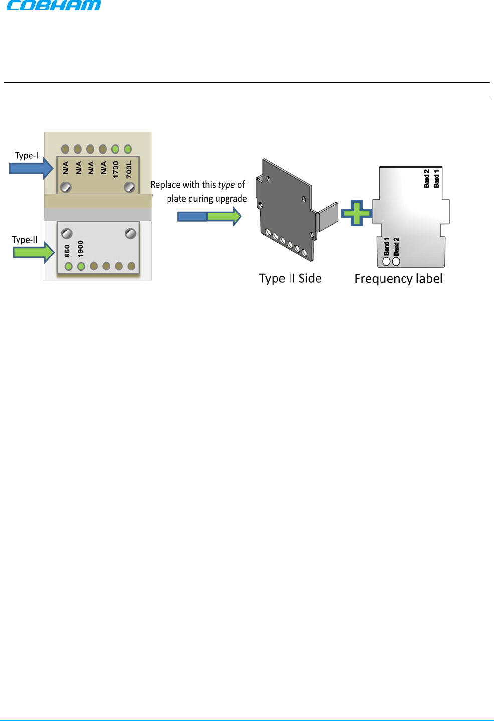
4.5.2.4 Combination of Type I and Type II DIGImini Units
NOTE: Assemble the label onto the plate; the relevant bands are on the side of the corresponding repeater.
Figure 4-15.Examples of Plate Used When Both Units are Type-I
Type I Side
DIGIMINI AMERICAS REPEATERS
PRODUCT DESCRIPTION AND USER’S MANUAL
Cobham Wireless – Coverage Date: 6-Jul-17 www.cobham.com/wireless
Document number: 00031UM Rev. 6.3 Page |4-13
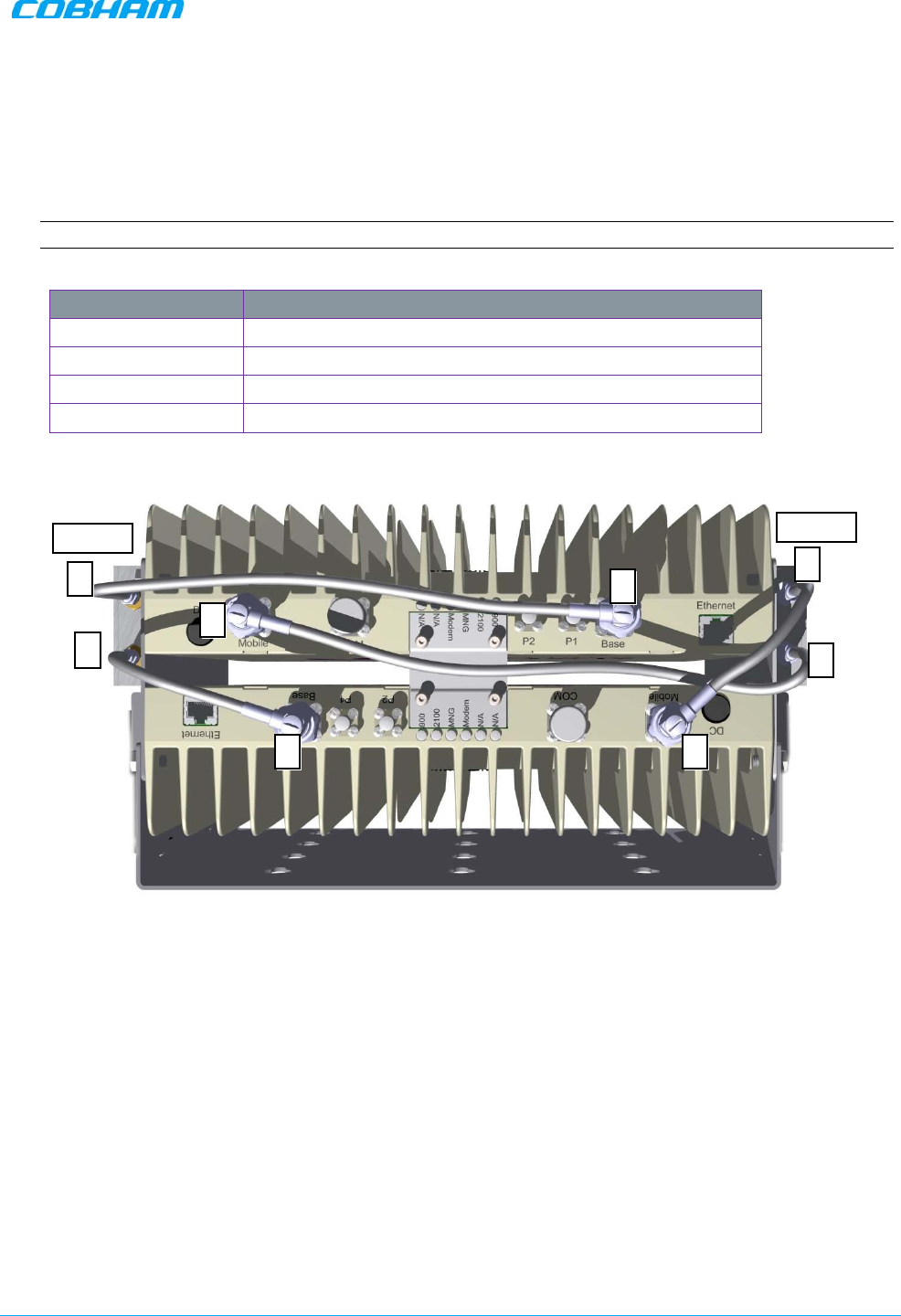
4.5.3 Connect SMA Jumper Cables
Connect SMA N-type jumper cables between Combiners and Repeater antenna ports according to
the illustration below:
NOTE: Be sure to use recommended Torque value.
Jumper Type Connect Between
Short (170mm) Connect between connectors labeled
1
(i.e
1 to 1
)
Short (170mm) Connect between connectors labeled
4
(i.e
4 to 4
)
Long (340mm) Connect between connectors labeled
2
(i.e
2 to 2
)
Long (290mm) Connect between connectors labeled
3
(i.e
3 to 3
)
Figure 4-16. DIGImini Quad-Band Jumper Connections
BASE
Mobile
3
3
2
2
4
4
1
1
DIGIMINI AMERICAS REPEATERS
PRODUCT DESCRIPTION AND USER’S MANUAL
Cobham Wireless – Coverage Date: 6-Jul-17 www.cobham.com/wireless
Document number: 00031UM Rev. 6.3 Page |4-14
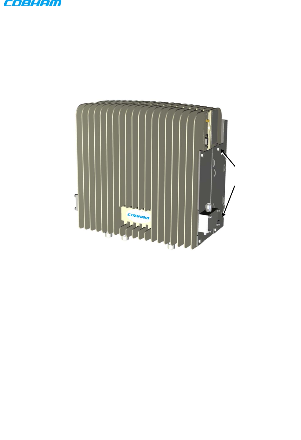
4.5.4 Mount and Secure Quad-Band Assembly
1. Referring to the following figure:
•
Carefully and securely pick
up the assembly.
• Hang the assembly on the wall bracket, fitting the
looser
wall-side Repeater Side Bracket screws
on the wall bracket.
• Tighten the loose screws on each side.
Figure 4-17. Mount Quadband Assembly on Wallbracket
Tighten screw
on wall-side
bracket
DIGIMINI AMERICAS REPEATERS
PRODUCT DESCRIPTION AND USER’S MANUAL
Cobham Wireless – Coverage Date: 6-Jul-17 www.cobham.com/wireless
Document number: 00031UM Rev. 6.3 Page |4-15
2. Two Power Supplies should be assembled on the wallbracket (one on each side of the
assembly). Mount one (if this is an upgrade and one is already mounted) or both (if this is a new
installation) as follows:
• Thread two ties through the loops in the bracket.
Figure 4-18. Insert Ties for Securing Power Supply
• Fit Power Supplies on ridge(s) on side of wallbracket.
• Secure the ties.
,
Figure 4-19. Secure Power Supply
Thread x2 ties through
loops (1x on bottom and
1x on top)
Ties
AC/DC
Converter PS
DIGIMINI AMERICAS REPEATERS
PRODUCT DESCRIPTION AND USER’S MANUAL
Cobham Wireless – Coverage Date: 6-Jul-17 www.cobham.com/wireless
Document number: 00031UM Rev. 6.3 Page |4-16
4.6 Before Connecting the Antennas or Power
Before connecting the antennas or power perform the procedures described in section 3.5.
4.7 Antenna Connections
CAUTION!! Do not connect the antenna cables to the Repeater before verifying the installation
parameters.
DO NOT POWER-UP the Repeater without either the antennas being connected or the antenna
connections terminated with dummy loads.
To connect the antennas to the Repeater
NOTE: If the coaxial cables are NOT weather-resistant type, wrap the exterior coaxial cables with insulation
and holding tape (Type 3M Rubber splicing tape) for environmental protection and to ensure longer lifetime.
1. Install the antenna cables along their path to the Repeater, and connect them to the Antennas.
NOTE: Be sure to use low loss cables.
2. Connect the Donor (Base) antenna to the rear port of the LEFT Combiner (connected to the
Repeater BASE ports). (Donor antenna specifications and installation criteria are described in section
2.1).
3. Connect the Service antenna to the rear port of the RIGHT Combiner (connected to the Repeater
MOBILE ports.) (Service antenna specifications and installation criteria are described in Chapter 2).
4. Verify all RF connectors are tightened and the cables and antennas are secured.
Figure 4-20. Service and Donor Antenna Connections
Donor Antenna
Service Antenna
DIGIMINI AMERICAS REPEATERS
PRODUCT DESCRIPTION AND USER’S MANUAL
Cobham Wireless – Coverage Date: 6-Jul-17 www.cobham.com/wireless
Document number: 00031UM Rev. 6.3 Page |4-17
4.8 Power Up
To power up
1. Connect each Power Supply (AC/DC Converter) output to a Repeater front panel DC power connector.
2. Connect each of the Repeater P.S. units’ to the AC power outlet.
Figure 4-21. Powering Up (shown with illustration of Combiner)
4.9 What Next?
• Installations
without
DIGImini Control Unit (DMCU) – continue to Chapter 5 - SETUP AND
CONFIGURATION
• Installations
with
DMCU – refer to the DMCU User Manual.
Connect to
110/240 VAC
Donor Antenna
Connect to Repeater front
panel DC connector

DIGIMINI AMERICAS REPEATERS
PRODUCT DESCRIPTION AND USER’S MANUAL
Cobham Wireless – Coverage Date: 6-Jul-17 www.cobham.com/wireless
Doc. No.: 00031UM Rev. 6.3 Page | 5-1
5 SETUP AND CONFIGURATION
NOTE: This section is relevant to installations that WITHOUT a DMCU. For installations with DMCU unit, refer
to the DMCU User Manual.
The Mini-Repeater is designed for simple plug-and-play operation, only requiring the setup of a number of
parameters (such as DL Output Power, bandwidth, and gain) through a local Web connection and verifying
that the system is operating properly.
The setup procedure consists of the following steps:
1. Open a local Web session to the Repeater.
If you are not familiar with the Cobham Wireless Web Access application, it is recommended to quickly
review the Navigating the Web GUI Application section.
2. Adjust the signal levels and configuring the sub-bands and verify that no Alarms are generated.
5.1 Open a Direct Local Web Session to the Repeater
NOTE: These instructions are valid only for installations
without
a DMCU.
The procedure consists of three steps:
• Connect the setup computer to the repeater’s Ethernet port.
• Configure the computer’s IP address to be in the same subnet as the repeater’s IP Address
• Login to the repeater
DIGIMINI AMERICAS REPEATERS
PRODUCT DESCRIPTION AND USER’S MANUAL
Cobham Wireless – Coverage Date: 6-Jul-17 www.cobham.com/wireless
Document number: 00031UM Rev. 6.3 Page |5-2
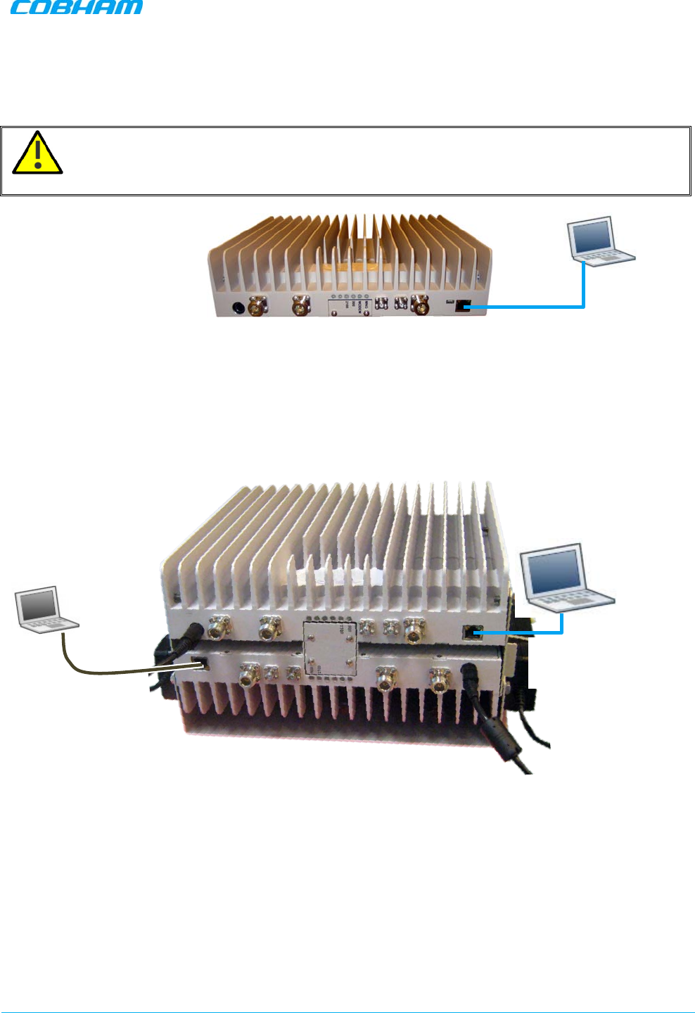
5.1.1 Connect the Computer to the Repeater
1. Connect the supplied Ethernet cross-cable from the computer to the Repeaters’ front panel.
ATTENTION! Do not connect the Repeater ETH port to the network. It may affect your network!
Remote management is available only via a DMCU.
Figure 5-1. Ethernet Connection to a Single DIGImini Repeater
2. If connecting to the Quad-band assembly, connect the cable to
any
of the two repeaters. The Web GUI
will allow for configuration of both repeaters.
Figure 5-2: Cascaded DIGImini Quad-band
Ethernet cross -
cable
Connect to
either unit
Ethernet
cross-cable
DIGIMINI AMERICAS REPEATERS
PRODUCT DESCRIPTION AND USER’S MANUAL
Cobham Wireless – Coverage Date: 6-Jul-17 www.cobham.com/wireless
Document number: 00031UM Rev. 6.3 Page |5-3
5.1.2 Configure the Computer’s Network Parameters
In order to open a session to the repeater, it is required to configure the computer’s network parameters to
be in the same subnet as the repeater.
To configure the computer network parameters
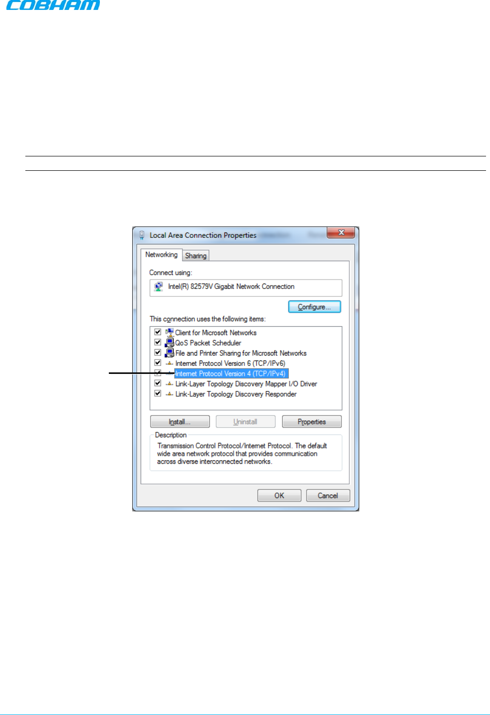
1. Access the Local Area Connection Properties dialog
NOTE: The procedure may differ according to your computer’s operating system.
• Access the Network and Sharing Centre.
• Choose Change Adapter Settings and select Local Area Connection. The Local Area
Connection Properties dialog appears.
Figure 5-3 Networking Tab
2. In the Items list, double-click Internet Protocol Version 4 (TCP/IPv4).
Select Internet
Protocol Version 4
DIGIMINI AMERICAS REPEATERS
PRODUCT DESCRIPTION AND USER’S MANUAL
Cobham Wireless – Coverage Date: 6-Jul-17 www.cobham.com/wireless
Document number: 00031UM Rev. 6.3 Page |5-4
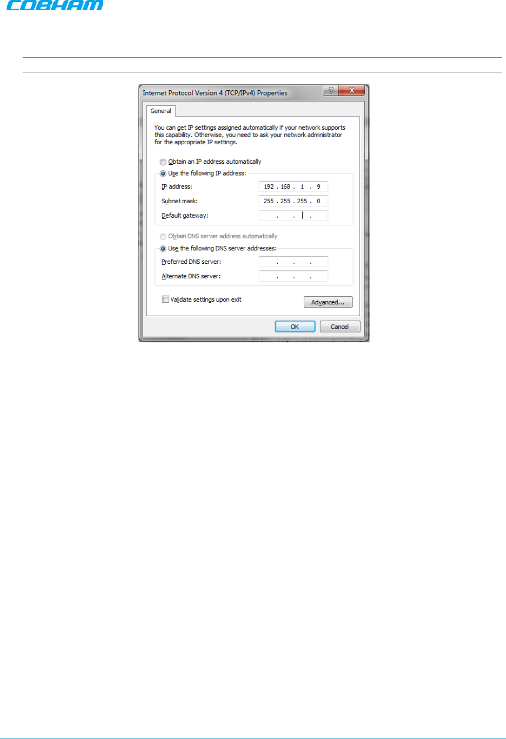
The Internet Protocol Version 4 (TCP/IPv4) Properties dialog appears.
Note: The Repeater is supplied with the default IP address 192.168.1.253.
Figure 5-4 IPv4 Properties dialog
3. Assign your computer an IP address in the same subnet, in order to communicate with the unit.
• In the IP address area:
• Enter the IP address 192.168.1.x, where ‘x’ can be any number between 2 and 250 inclusive. For
example, (192.168.1.9)
• Define the subnet mask as shown (255.255.255.0)
• Click OK. The computer communication parameters are now defined and you can open a session to
the Repeater.
DIGIMINI AMERICAS REPEATERS
PRODUCT DESCRIPTION AND USER’S MANUAL
Cobham Wireless – Coverage Date: 6-Jul-17 www.cobham.com/wireless
Document number: 00031UM Rev. 6.3 Page |5-5
5.1.3 Login to the Repeater
To login to the repeater
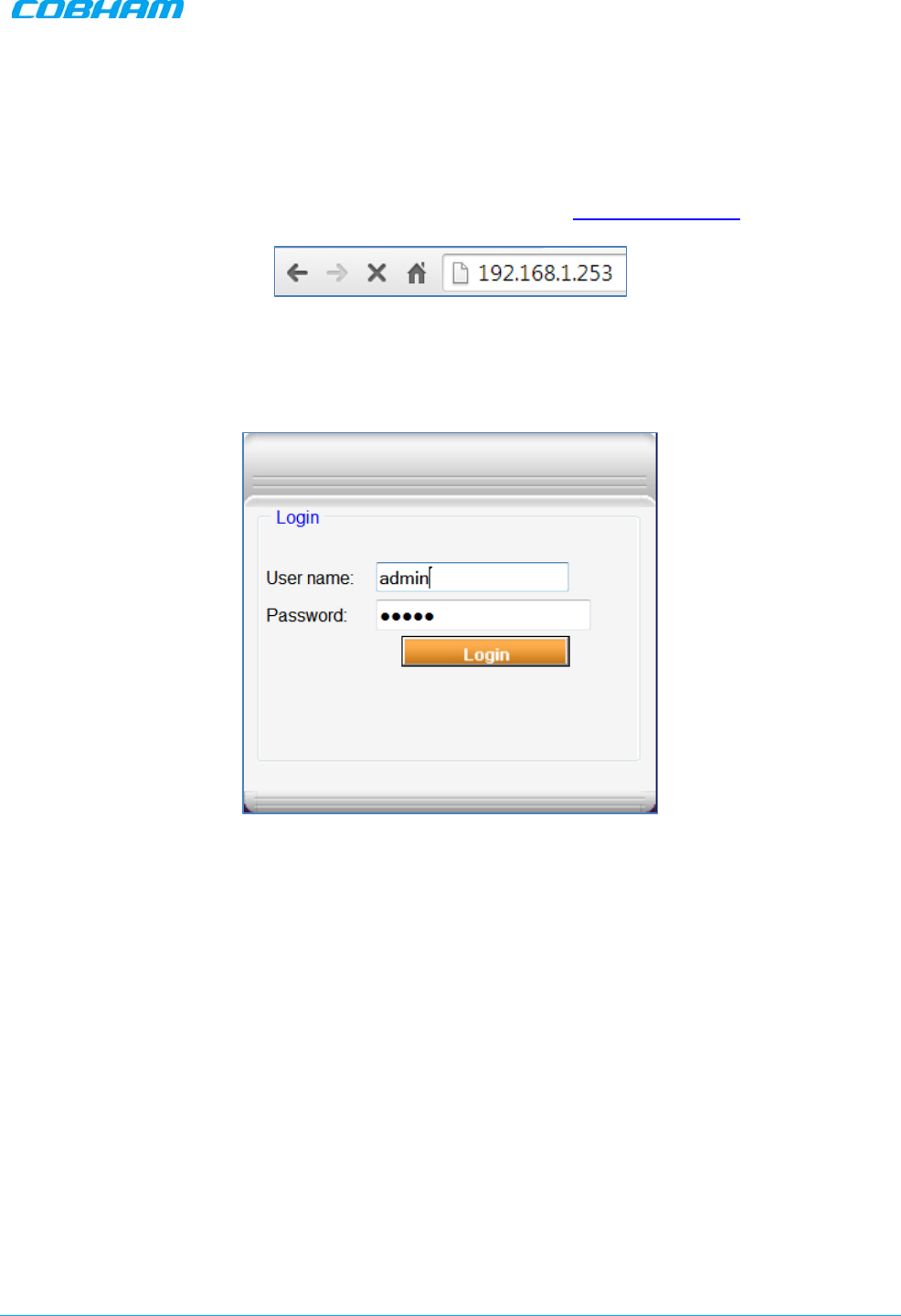
1. Open a standard browser.
2. In the address line, enter the default IP address of the Repeater. http://192.168.1.253
Figure 5-5. Repeater’s default IP Address
A session will be established with the Repeater an the login dialog appears.
Figure 5-6 Login Dialog
3. Type the default User Name admin and the default Password admin.
Note that both are case sensitive and must be entered with lower case letters.
4. Click Login. The application main window appears.
5. Quickly review the following section describing the application window and then proceed to configure
the signal levels according to section 5.3.
DIGIMINI AMERICAS REPEATERS
PRODUCT DESCRIPTION AND USER’S MANUAL
Cobham Wireless – Coverage Date: 6-Jul-17 www.cobham.com/wireless
Document number: 00031UM Rev. 6.3 Page |5-6
5.2 Navigating the Web GUI Application
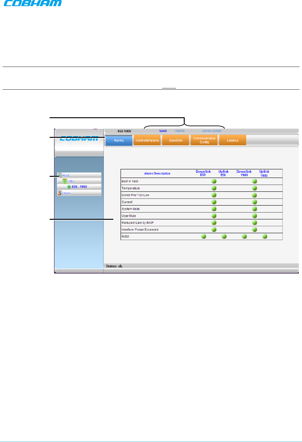
This section describes how to navigate the Web Management application. The Web Access interface provides
Repeater RF parameters control and monitoring options. The displayed bands depend on the supported
configuration: Dual- or Quad-band configuration.
NOTE: The CMU (Control Monitoring Unit) item in the topology tree is only accessible for sessions opened
via the Digital Monitoring Control Unit (DMCU) - see the DMCU User Manual for details. For sessions
opened by direct connection to a DIGImini front panel, the CMU item will appear but will not be accessible.
Figure 5-7. Example of Web GUI Screen (shows dual-band)
Topology Tree
Items
Pane related to
selected tree
item
Operation
Buttons
Tabs related to
selected Tree item
DIGIMINI AMERICAS REPEATERS
PRODUCT DESCRIPTION AND USER’S MANUAL
Cobham Wireless – Coverage Date: 6-Jul-17 www.cobham.com/wireless
Document number: 00031UM Rev. 6.3 Page |5-7
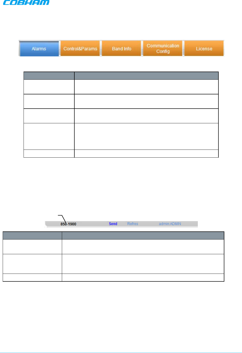
5.2.1 Band Pane and Tabs
The upper area of each selected pane shows the tabs corresponding to that pane.
Item Description / Values
Alarms Displays various alarms generated by the Repeater and enables
monitoring. See details in section 6.2.1
Control and Params Used for adjusting RF parameters and channel configuration
(signal level, gain and bandwidth). See details in section 5.3
Band Info
Shows information on the selected band, including valid
definable bandwidth pre sub-band (see section 5.3.2).
Communication
Config Relevant only if you have purchased the appropriate license
file.
If the option is supported – it provides IP Address definitions
and SNMP Destination addresses used for remote monitoring.
License Used to download licenses for additional options.
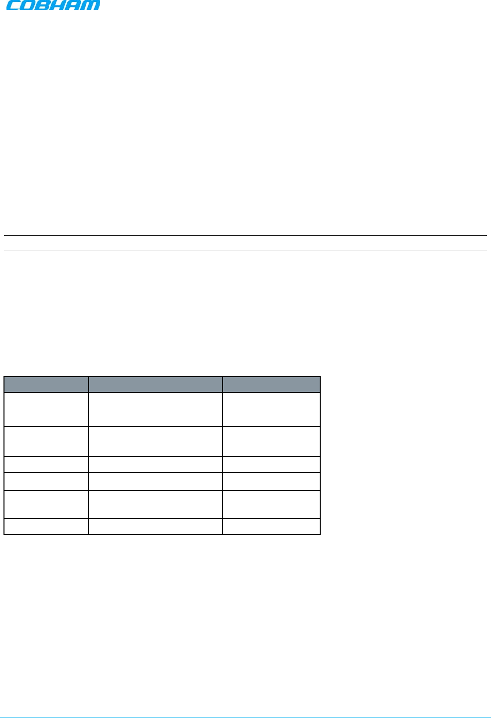
5.2.2 Operation Buttons
The following Operation buttons are available.
Item Description / Values
Selected Tree Item Shows the currently selected topology tree item.
Values: Band (e.g. 850-1900), Users
Send Click after completing the new data input and values update in any
screen in order to insert the new values into the Repeater, and
implement the changes
Refresh Click to refresh the current screen and update the displayed data
5.3 Signal Levels and Channel Configuration
This section provides a description of the RF Gain setting criteria (set via the Controls and Params Pane), the
criteria determining the number of available bands and a step-by-step procedure of the signal level and
channel configuration procedure.
Selected Tree
item
DIGIMINI AMERICAS REPEATERS
PRODUCT DESCRIPTION AND USER’S MANUAL
Cobham Wireless – Coverage Date: 6-Jul-17 www.cobham.com/wireless
Document number: 00031UM Rev. 6.3 Page |5-8
5.3.1 RF Gain Setting Criteria
The RF Gain is set automatically by the Repeater’s SALC function. The function sets the optimum gain
without exceeding the isolation limit.
The gain range is up to 73dB for
all bands
and is set by default to its maximum value.
The gain will then be modified automatically to its optimum value by the SALC mechanism.
This mechanism
performs gradual learning of traffic load characteristics and adjusts the Repeater RF Gain accordingly. (See
section 1.2 for more information on the SALC mechanism).
5.3.2 Bandwidth and the Number of Available Sub-Bands
Each repeater supports up to two bands, where a maximum total e
ight sub-bands
may be defined for both
bands (e.g. two sub-bands for one band and six sub-bands for the other band).
NOTE: Since some sub-bands require more resources, less than eight sub-bands may be available.
The sub-bands are available resources are listed in the Band Info tab of the repeater.
This section provides a general description of the sub-band resource allocation as well as the Band Info tab.
5.3.2.1 Sub-band Resource Allocation
A maximum e
ight sub-bands
may be defined per repeater (single- or dual-band). The number of available
sub-bands or channels depends on the technology and selected bandwidth as detailed below (note that
some bandwidths (e.g. 15 or 20MHz at 1900MHz WCDMA) take up two channel resources).
The following table summarizes the number of available sub-band resources under various configurations.
Technology Filter BW Resources
GSM 200KHz – 11MHz
(in 200KHz steps) 1
GSM 11.2MHz – 20MHz
( in 200KHz steps) 2
WCDMA 5MHz, 10MHz 1
WCDMA 15MHz, 20MHz 2
LTE
1.4MHz, 3MHz, 5MHz,
10MHz 1
LTE 15MHz, 20MHz 2
5.3.2.2 Band Information Window
The band information window provides general information on the repeater; this includes, Serial Number,
Build versions, System ID (used when acquiring license files) and resources available for various filters.
To access the Band Information window
1. From the Tree Pane, select the band item in the tree (e.g. 900-2100).
2. Select the Band Info tab. The relevant parameters are displayed.
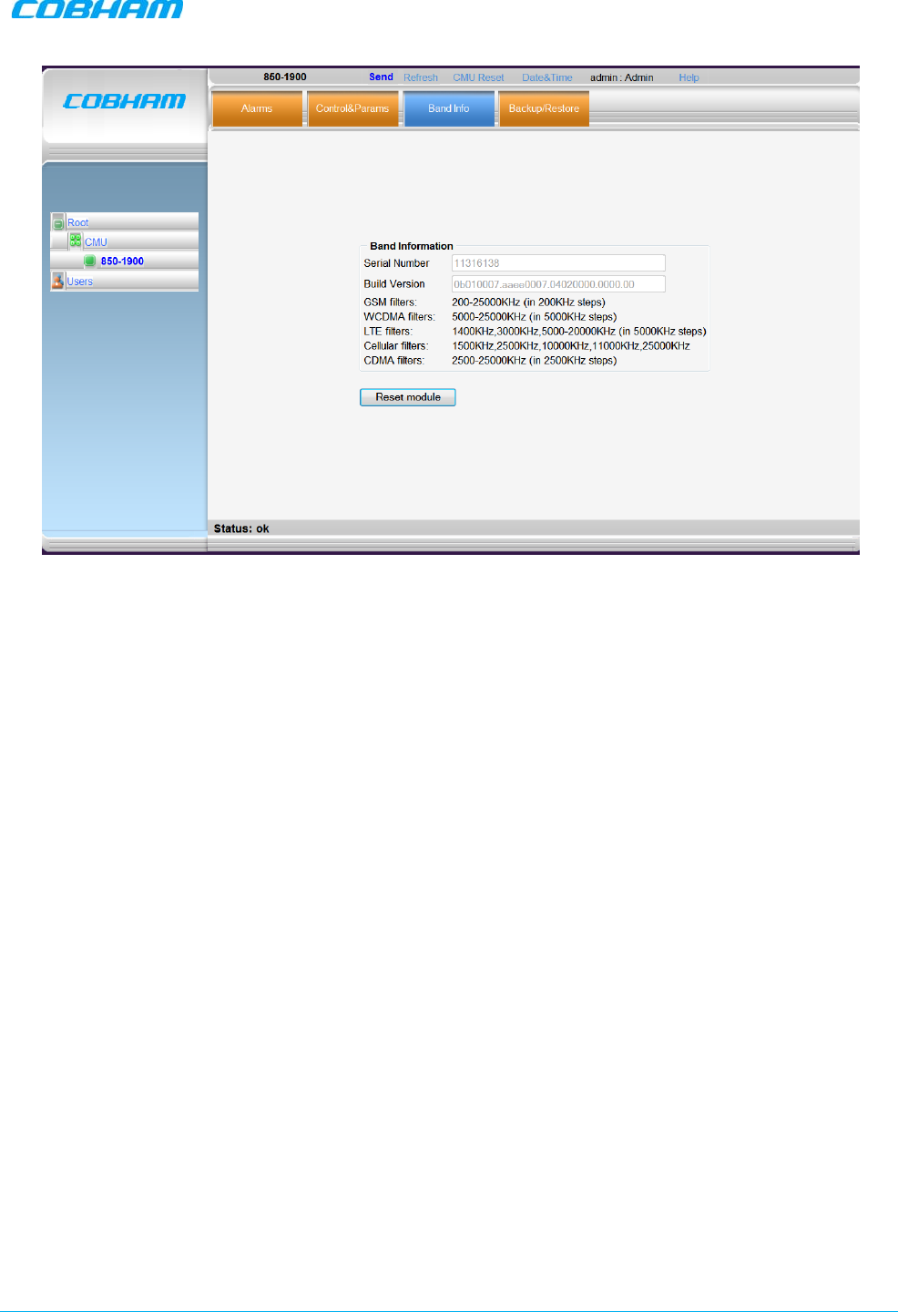
DIGIMINI AMERICAS REPEATERS
PRODUCT DESCRIPTION AND USER’S MANUAL
Cobham Wireless – Coverage Date: 6-Jul-17 www.cobham.com/wireless
Document number: 00031UM Rev. 6.3 Page |5-9
Figure 5-8. Info Tab
5.3.3 Adjusting the Signal Levels and Configuring Channels
The Control and Params (parameters) window is used to configure the sub-bands and Max UL/DL Power
for the selected band. A dedicated filter configuration dialog is provided for each band. The dialogs and
configuration procedures are identical for each band,
except for the parameter values
.
Up to eight sub-bands referred to as
filters
can be defined, where each sub-band is
individually
defined by
setting the following:
• Bandwidth - start and stop frequency - see appendices B and C for parallel GSM channels.
• Maximum power
• Maximum gain
• Gain delta
The defined sub-bands are displayed in the lower part of the screen for reference.
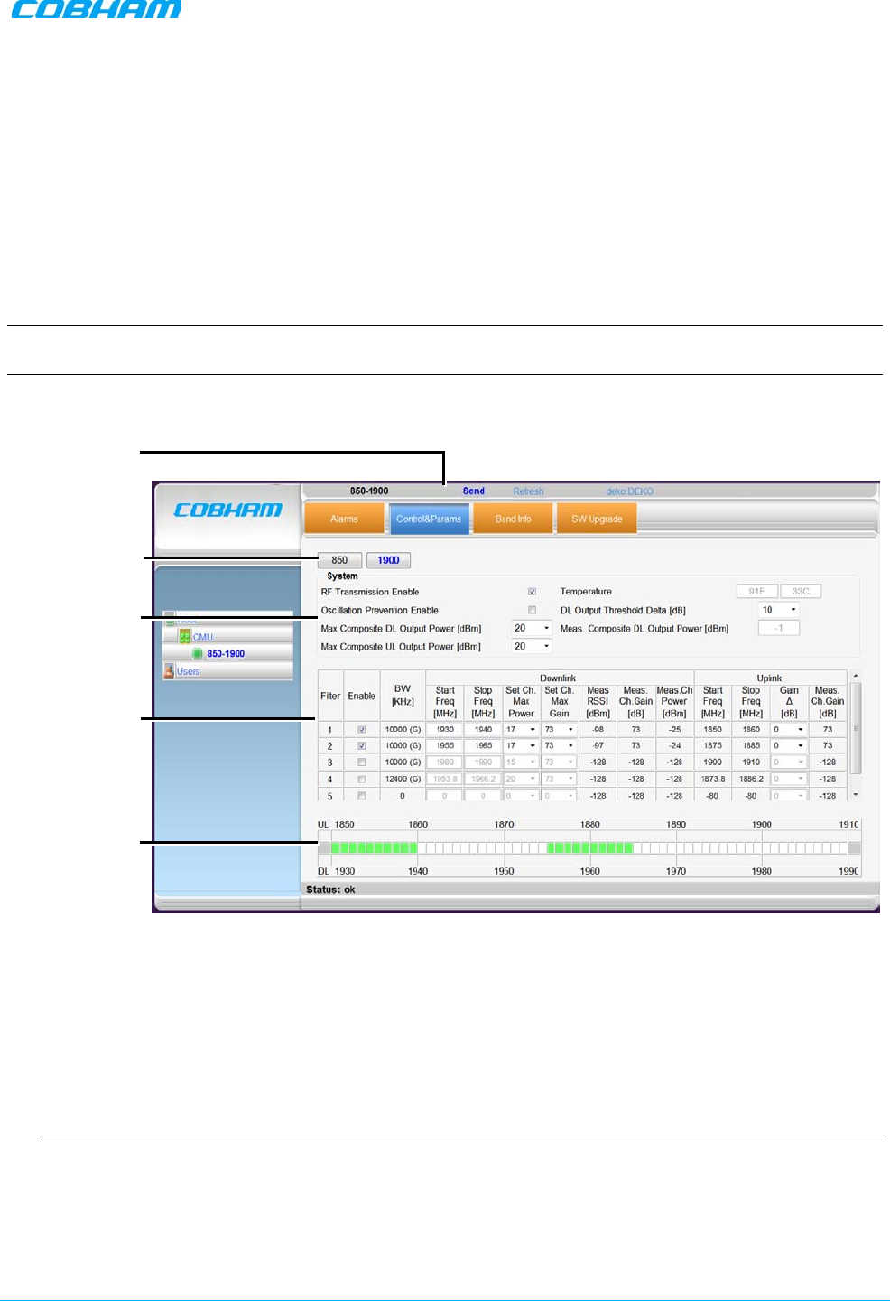
DIGIMINI AMERICAS REPEATERS
PRODUCT DESCRIPTION AND USER’S MANUAL
Cobham Wireless – Coverage Date: 6-Jul-17 www.cobham.com/wireless
Document number: 00031UM Rev. 6.3 Page |5-10
To adjust the signal levels and configure the channels:
1. In the left pane (Topology Tree), select the
bands
item (e.g. 850-1900) which includes the Band item
whose sub-bands are to be configured.
2. Click the Control and Params tab. For dual/quad band configurations,
click the required band
for
configuration and the corresponding pane appears.
The window is divided into the following areas:
• System – overall parameters for the
selected service.
• Filter definitions – used to define up to eight sub-bands and their RF parameters.
• Sub-bands view – graphical display of defined sub-bands for the service.
NOTE: You may define a total of eight sub-bands for both bands; e.g. 2 sub-bands for the 850MHz band
and 6 sub-bands for the 1900MHz band (see section 5.3.2 for details).
Figure 5-9. Control and Params Tab (example shows dual-band)
3. Set the System Level parameters:
• Verify that the RF Transmission Enable parameter is checked.
• Set the Max Composite DL Output Power according to your site requirements and click Send.
The Measured Composite DL Output Power is displayed in the adjacent field.
If the composite output power exceeds the defined value, the Smart ALC feature begins working.
• Set the Max Composite UL Output Power according to your site requirements.
Additional parameters (not required for initial setup) are:
• Oscillation Prevention Enable - Enables oscillation detection mechanism that maintains repeater
functionality.
• Temperature - Displays Repeater ambient temperature.
• DL Output Threshold Delta (dB) - the delta from the set Composite Output Power, below which the
alarm 'Donor power is too low' is activated.
Click Send to
save changes
Band dedicated
RF Config. tabs
General
parameters
Sub-band
definition options
(for the selected
band)
Display of sub-
band definitions
(for the selected
band)

DIGIMINI AMERICAS REPEATERS
PRODUCT DESCRIPTION AND USER’S MANUAL
Cobham Wireless – Coverage Date: 6-Jul-17 www.cobham.com/wireless
Document number: 00031UM Rev. 6.3 Page |5-11
For example, if the DL Output Threshold value is set to 8dB, when the
Measured
Composite DL output
power is 8dB less than the
set
Composite Output Power, an alarm is generated.
• Meas. Composite DL Output Power – displays the currently measured output signal level.
4. To configure each sub-band:
• Checkmark Enable. The configuration parameters in that row will be available.
• In the Downlink area, set the Start and Stop DL Frequency (MHz). (The Uplink Start and Stop
frequencies will be automatically allocated.)
NOTE: For tables of GSM frequencies Vs channels, refer to Appendix B (GSM 900 MHz) and
Appendix C (GSM 1800 MHz).
The defined BW will be displayed in the BW KHz column (to the left of the Start Frequency).
• Set the (Downlink) Max Gain as follows: by default, the MAX Gain (DL) parameter is set to its
highest level (73dB). Change the Channel Max Gain (DL) according to the measured/calculated
input power and isolation measurements.
• The recommended Maximum Gain setting is approximately 15 dB less than the isolation between the
service and donor antennas.
5. If the site NOISE LEVEL is high enough to cause interference, adjust the noise level as follows:
• Adjust the Gain Delta parameter – this sets the delta between the uplink and downlink gain (so the
uplink gain is relatively lower than the downlink gain.
• Click Send.
• Repeat the procedure until the desired coverage is achieved.
6. More information on parameters for the
selected
sub-band:
• DL Set Ch. Max. Gain Sets the power for the antennas. The value is about 15 dB less than the
isolation between the donor antenna and the mobile antenna.
• The Value defined in the DL path is reflected in the UL path, however to define different UL
and DL path values the Gain Delta parameter is used and its defined value is added to the UL
value.
• DL Measured RSSI - measured DL signal.
• DL Measured Ch. Gain - measured DL Gain (dB) for the selected sub-band.
• DL Measured Ch. Power - measured Power (dBm) for the selected sub-band.
• UL Gain Δ - used for noise control. Sets the difference between UL and DL gain.
• UL Measured Ch. Gain - measured UL Gain (dB) for the selected sub-band.
7. Click Send (top window area option).
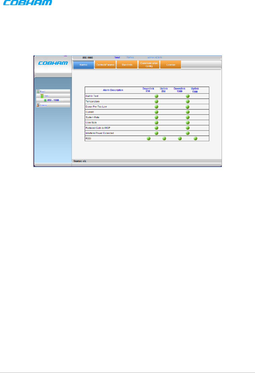
DIGIMINI AMERICAS REPEATERS
PRODUCT DESCRIPTION AND USER’S MANUAL
Cobham Wireless – Coverage Date: 6-Jul-17 www.cobham.com/wireless
Document number: 00031UM Rev. 6.3 Page |5-12
8. After the channels have been configured and the required coverage is attained for the location, verify
that no Alarms are generated:
• Click the Alarms tab
• Verify that all the indicators are GREEN in the Alarms tab
Figure 5-10. Example of Alarms Tab
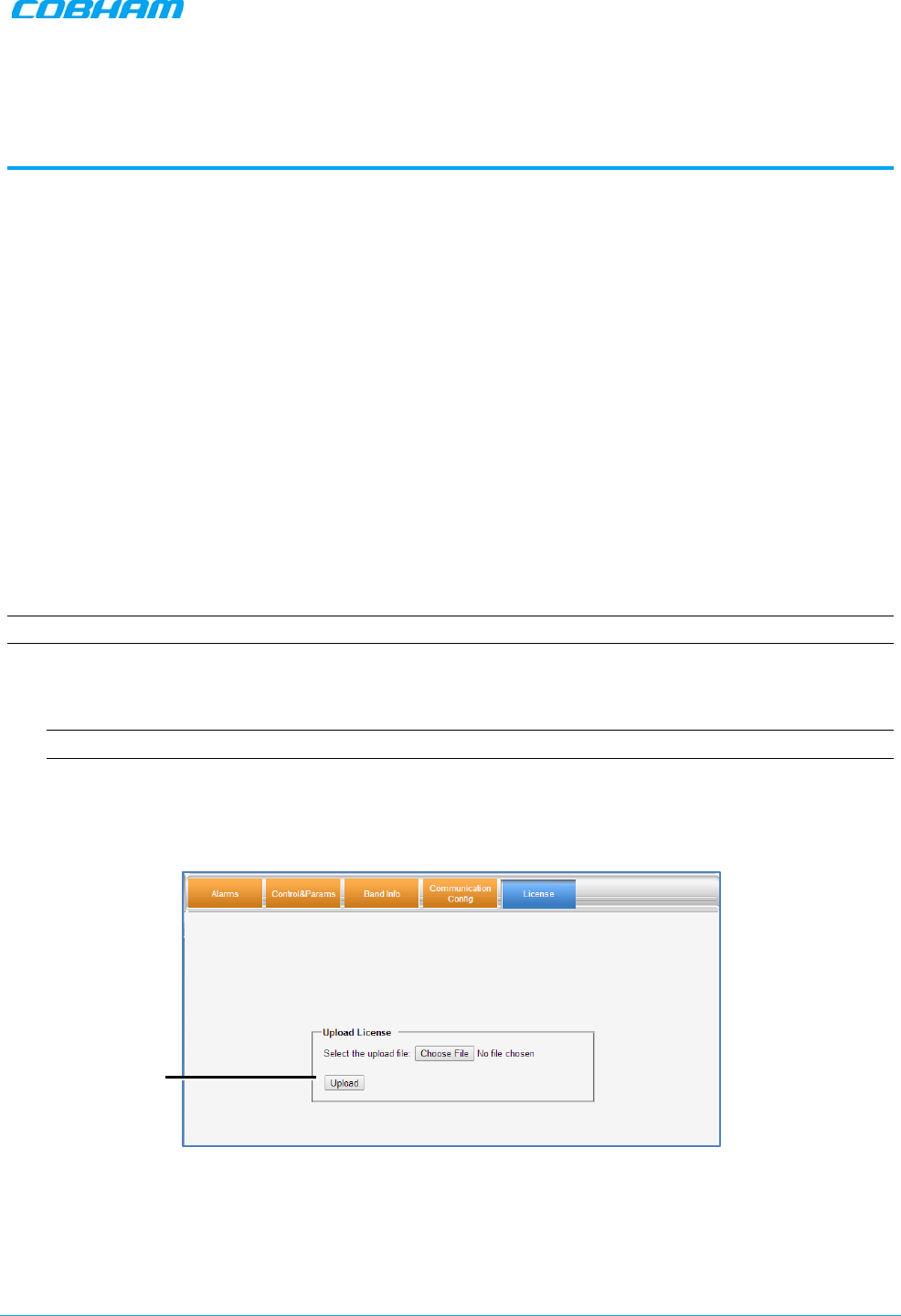
DIGIMINI AMERICAS REPEATERS
PRODUCT DESCRIPTION AND USER’S MANUAL
Cobham Wireless – Coverage Date: 6-Jul-17 www.cobham.com/wireless
Doc. No.: 00031UM Rev. 6.3 Page | 6-1
6 ADMINISTRATION, MONITORING AND
TROUBLESHOOTING
This chapter describes the following:
• Basic administration operations such as uploading license files and upgrading features
• Description of repeater GUI alarms and front panel LEDs
6.1 Administrative Operations
This section includes the following:
• License file upload
• Single-band to dual-band upgrade
• Upgrade to support connection to Ethernet and an External Modem
6.1.1 License File Upload
This section describes how to upload a license file to the repeater. License files are used to upgrade the
repeater to support additional features such as dual-band (for single-band repeaters) and support for basic
remote monitoring.
NOTE: Each feature is implemented using a DEDICATED license file.
To upload a license file
1. Contact your Cobham Wireless service representative and purchase the option.
NOTE: You will be required the System ID listed in the Band Info tab (section 5.3.2.2).
2. Once the appropriate license file is available, save the file to an accessible directory.
3. Open a session to your repeater, click the
band
item and select the License tab.
4. Browse for the file (Choose File) and then click Upload.
Figure 6-1. License for Updating to Dual-band
Choose the
file and then
Upload
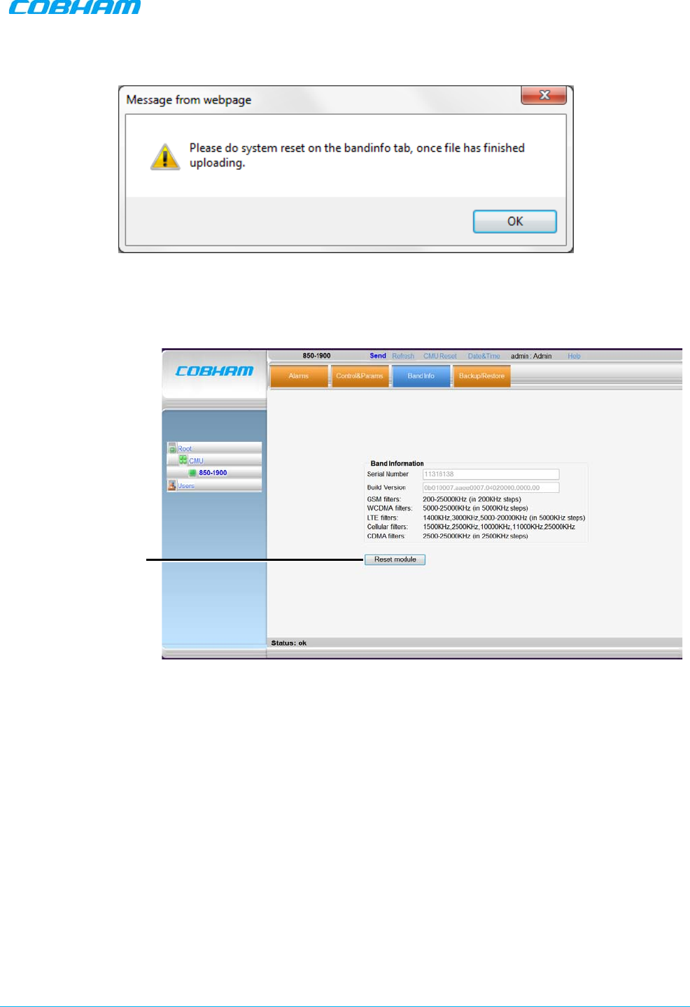
DIGIMINI AMERICAS REPEATERS
PRODUCT DESCRIPTION AND USER’S MANUAL
Cobham Wireless – Coverage Date: 6-Jul-17 www.cobham.com/wireless
Document number: 00031UM Rev. 6.3 Page |6-2
After the upload has been completed, you will be prompted to reset the unit.
Figure 6-2. Reset Unit Prompt
5. Select the Band Info tab and click Reset System. The repeater will reset and the relevant options will
be available.
Figure 6-3. Reset Unit
6.1.2 Dual-band Support
To configure a single-band repeater to support two bands
Upload the
appropriate
license file according to section 6.1.1. The second band will be displayed in the
Topology Tree and the relevant tabs will be updated in the display area.
Reset the
repeater
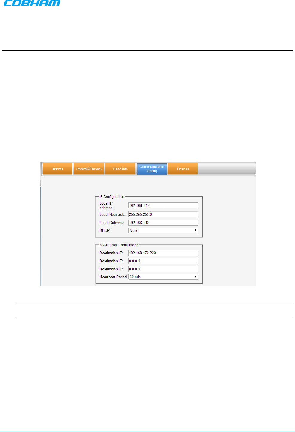
DIGIMINI AMERICAS REPEATERS
PRODUCT DESCRIPTION AND USER’S MANUAL
Cobham Wireless – Coverage Date: 6-Jul-17 www.cobham.com/wireless
Document number: 00031UM Rev. 6.3 Page |6-3
6.1.3 Connection to an Ethernet Network
NOTE: This is not relevant for installations with DMCU.
Units without DMCU can be upgraded, by purchasing the appropriate license file, to support some basic
remote management options through connection to an Ethernet network.
To configure for connection to the Ethernet Network
1. Purchase and upload the appropriate license file according to section 6.1.1. The relevant tabs will be
updated and become available.
2. To configure the unit for connection to the Ethernet network:
• Select the
band
item.
• Click the Communication Config tab.
• Set the IP Configuration parameters:
• Set DHCP to None.
• Configure the Local IP Address, Local Netmask and Local Gateway parameters.
3. You can configure up to three destination addresses to which traps will be sent.
NOTE: By default, a trap will be sent if a Heartbeat signal is not detected for 60 minutes. The heartbeat
period may be modified or disabled (set to ‘0’).
4. Click Send.
5. Connect the unit Ethernet port to the network.
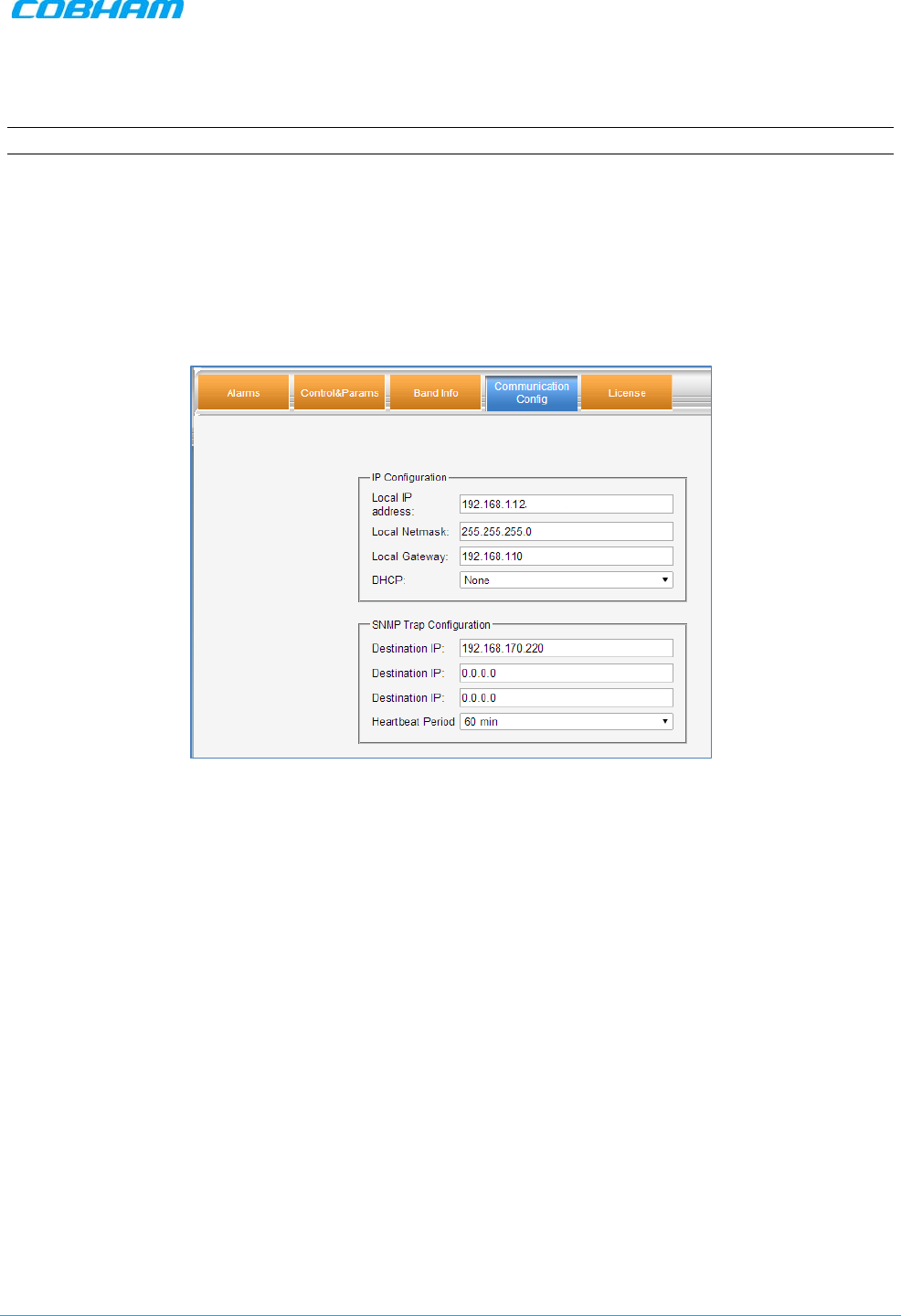
DIGIMINI AMERICAS REPEATERS
PRODUCT DESCRIPTION AND USER’S MANUAL
Cobham Wireless – Coverage Date: 6-Jul-17 www.cobham.com/wireless
Document number: 00031UM Rev. 6.3 Page |6-4
6.1.4 Connection to an External Modem
NOTE: This option is relevant to installations without DMCU.
Units without DMCU can be upgraded to support some basic remote management options through
connection to an external modem. (For full remote management capabilities, the DMCU is required).
To configure for connection to an External Modem
1. Download the appropriate license file according to section 6.1.1. The relevant tabs will be updated and
become available.
2. Select the
band
item and click the Communication Config tab.
3. Set DHCP to None.
4. Set the IP Address parameters as follows:
• IP Address – set to be in the SAME SUBNET as the internal IP Address of the MODEM.
For example:
If the Modem IP Address is 192.168.1.10
Then set the Repeater Local IP Address to 192.168.1.12
• Local Netmask – set to 255.255.255.0
• Local Gateway set to be EXACTLY the same as the internal IP Address of the MODEM. For
example:
If the Modem IP Address is 192.168.1.10
Then set the Repeater Local Gateway to 192.168.1.10
5. Click Send.
6. Connect the unit Ethernet port to the external modem.
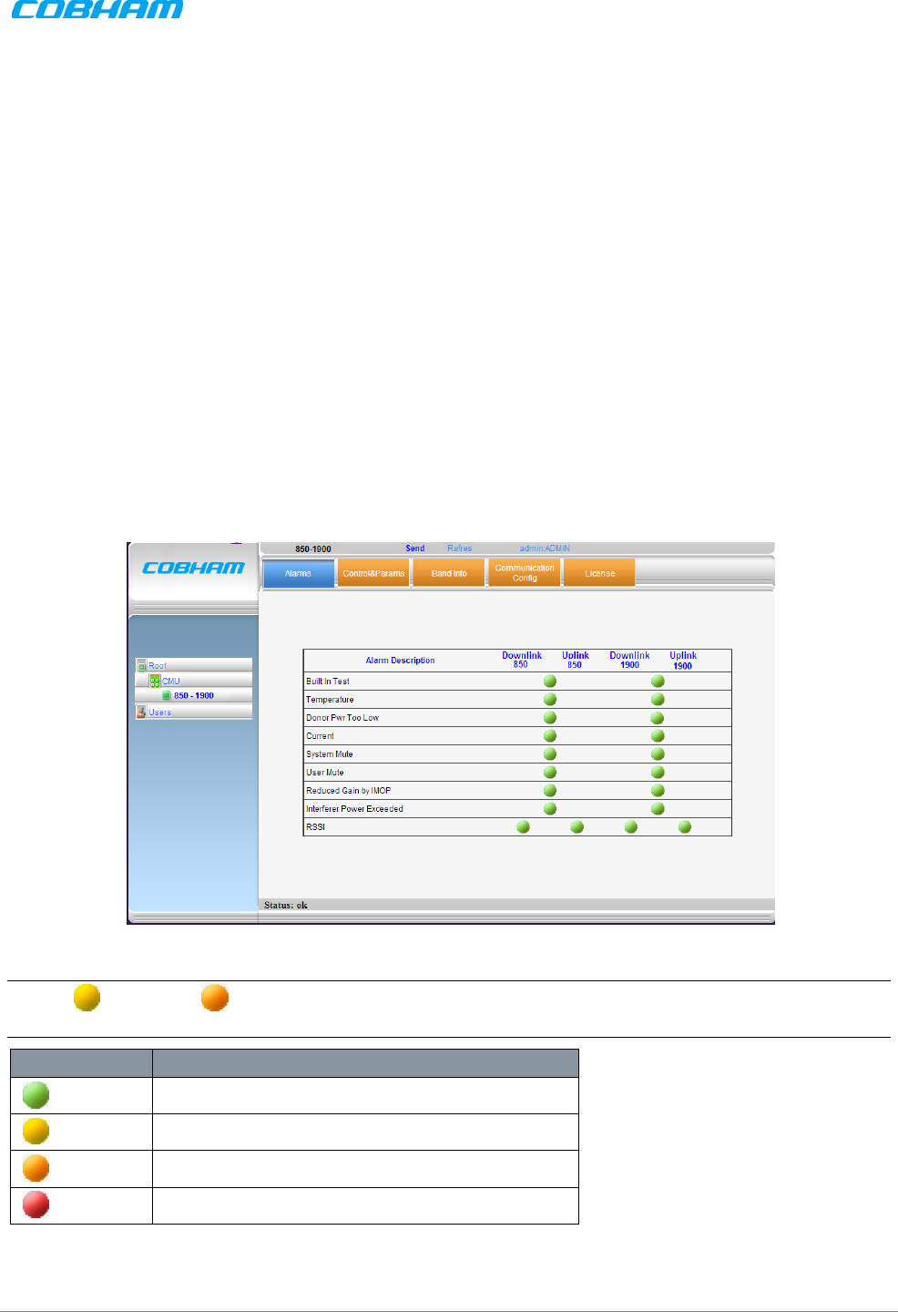
DIGIMINI AMERICAS REPEATERS
PRODUCT DESCRIPTION AND USER’S MANUAL
Cobham Wireless – Coverage Date: 6-Jul-17 www.cobham.com/wireless
Document number: 00031UM Rev. 6.3 Page |6-5
6.2 Monitoring and Troubleshooting
DIGImini provides two types of indications of Repeater failure:
• Alarms screen in Web access application
• Status LEDs on Dual-Band Repeater front panel
The following sections provide a description of the troubleshooting procedures according to the Repeater
LED indicators and the Web access Alarms.
6.2.1 Repeater Alarms and Troubleshooting
The Alarms tab provides the alarms generated by the Repeater, enabling the user to monitor the system
operation.
To access the Alarms window
From the Tree Pane, select the band item and choose the Alarms tab. The relevant parameters are
displayed for the supported bands.
Alarm severity
NOTE: Yellow and Orange level LEDs are only available if the unit is connected to DMCU;
otherwise, only RED and GREEN LEDs are available.
Color Description
Green OK
Yellow Warning. Does not require immediate action
Orange Major. Higher priority, requires user attention
Red Critical. Requires user’s immediate action

DIGIMINI AMERICAS REPEATERS
PRODUCT DESCRIPTION AND USER’S MANUAL
Cobham Wireless – Coverage Date: 6-Jul-17 www.cobham.com/wireless
Document number: 00031UM Rev. 6.3 Page |6-6
Alarm Descriptions
Alarm Fault and most probable cause and Recommendation
Built In Test Description: Self test.
Possible causes: Hardware failure, Circuitry failure, Software failure
Recommended action: Wait 12 hours before contacting Cobham Wireless Support
Temperature Description: High temperature indicated
Possible causes: Unit temperature becomes high due to excessive heat.
Recommended action: Check the Repeater case for external causes (sun, hot
environment, air flow is blocked). Eliminate the reason for excessive heat.
Donor Power Too
Low Description: The signal from the Donor antenna is too low.
Recommended action: Check connections and antenna position.
(PAmp) Current Description: Generates an alarm when the Power exceeds the allowed limits.
Possible causes: Fault in the DL or UL path, Downlink (Uplink) power amplifier
module outputs a low current.
Recommended action: Check the LEDs status in the Repeater
System Mute
Description. Generates an alarm when Repeater amplification is muted
(automatically).
Possible causes: Oscillation detected, Power at coverage port too high, Synthesizer
failure, Hardware failure, Software failure, Out-of-band emissions out of spectrum,
Interferer Power exceeded, Temperature.
Recommended action: Contact Cobham Wireless Support
User Mute Description: Repeater amplification is muted.
Possible causes: Manual shutdown performed by operator.
Recommended action: Review unit’s log
Reduced Gain by
IMOP Description: Alarm is generated when the IMOP mechanism was activated and the
system reduces gain in order to respond to detected oscillations.
Recommended action: Check the Donor and Mobile antenna installations for
isolation. After isolation is within the required levels, the system will automatically
increase gain (since it will no longer affect oscillations).
Interferer Power
Exceeded Description: Alarm is activated if external interference is at a level that may affect
the operation of the unit.
Recommended action: It is recommended to identify the source of the interference
and distance the source or the unit from each other.
NOTE: When the interferer is at HIGH Level it can cause the RSSI alarm to be ON
as well
RSSI Description: Generates an alarm when a high donor input signal causes system
gain reduction

DIGIMINI AMERICAS REPEATERS
PRODUCT DESCRIPTION AND USER’S MANUAL
Cobham Wireless – Coverage Date: 6-Jul-17 www.cobham.com/wireless
Document number: 00031UM Rev. 6.3 Page |6-7
6.2.2 DIGImini LED Troubleshooting
The DIGImini repeater includes six LEDs on its front panel (see section 1.6.1). The following table provides a
description of the LED troubleshooting procedures.
Indicator Description
Band Specific LED
(i.e 900/1800/2100)
One Indicator per band :
RED Steady - service muted due to general fault
Blinking – service muted by user
ORANGE Blinking – service initiating on power up or reset
Steady – high DL/UL signal or VSWR
GREEN and ORANGE Blinking- Reduced gain by IMOP
GREEN Blinking – DL power below threshold
Steady - normal service operation
(Ethernet) MNG Relevant only if connected to DMCU:
Green Blinking – normal operation of CCD
(Ethernet) Modem Relevant only if connected to DMCU:
• Green Steady - modem is either not defined, or defined modem is
operating normally.
• Orange Steady– modem is trying to connect
• Red Steady– modem failed to connect

DIGIMINI AMERICAS REPEATERS
PRODUCT DESCRIPTION AND USER’S MANUAL
Cobham Wireless – Coverage Date: 6-Jul-17 www.cobham.com/wireless
Document number: 00031UM Rev. 6.3 Page |A- 1
Appendix A: Specifications
700 MHz Frequency band Uplink Downlink
Operating Frequency Range Lower band - 698-716MHz
or
Upper band - 776 - 787MHz
Lower band - 728-746MHz
or
Upper band - 746 - 757MHz
Output power at antenna port
(composite)(*) 21dBm 21dBm
Pass band maximum gain 73dB 73dB
Gain attenuation range 0-25dB (in 1dB steps) 0-25dB (in 1dB steps)
Pass band ripple ± 2.5dB ± 2.5dB
Noise Figure @ max gain 6dB 6dB
Propagation delay 6 μsec 6 μsec
Number of filters per band(**) Up to 8 Up to 8
1700 MHz (AWS1 +3) Frequency band Uplink Downlink
Operating Frequency Range(***) 1710-1780MHz 2110-2180MHz
Output power at antenna port
(composite) (*) 20dBm 20dBm
Pass band maximum gain 73dB 73dB
Gain attenuation range 0-25dB (in 1dB steps) 0-25dB (in 1dB steps)
Pass band ripple ± 2.5dB ± 2.5dB
Noise Figure @ max gain 6dB 6dB
Propagation delay 6 μsec 6 μsec
Number of filters per band(**) Up to 8 Up to 8
850MHz (Cellular) and
SMR 800 (Upper 7MHz) Frequency band Uplink Downlink
Operating Frequency Range 817-849MHz 862-894MHz
Output
power at antenna port
(composite) (*) 21dBm 21dBm
Pass band maximum gain 73dB 73dB
Gain attenuation range 0-25dB (in 1dB steps) 0-25dB (in 1dB steps)
Pass band ripple ± 2.5dB ± 2.5dB
Noise Figure @ max gain 6dB 6dB
Propagation delay 6 μsec 6 μsec
Number of filters per band(**) Up to 8 Up to 8
1900 MHz (PCS) Frequency band Uplink Downlink
Operating Frequency Range 1850-1915MHz 1930-1995MHz
Output power at antenna port
(composite) (*) 20dBm 20dBm
Pass band maximum gain 73dB 73dB
Gain attenuation range 0-25dB (in 1dB steps) 0-25dB (in 1dB steps)
Pass band ripple ± 2.5dB ± 2.5dB
Noise figure @ max gain 6dB 6dB

DIGIMINI AMERICAS REPEATERS
PRODUCT DESCRIPTION AND USER’S MANUAL
Cobham Wireless – Coverage Date: 6-Jul-17 www.cobham.com/wireless
Document number: 00031UM Rev. 6.3 Page |A- 2
Propagation delay 6 μsec 6 μsec
Number of filters per band(**) Up to 8 Up to 8
2600 MHz Frequency band Uplink Downlink
Operating Frequency Range 2500-2570MHz 2620-2690MHz
Output power at antenna port
(composite) (*) 20dBm 20dBm
Pass band maximum gain 73dB 73dB
Gain attenuation range 0-25dB (in 1dB steps) 0-25dB (in 1dB steps)
Pass band ripple ± 2.5dB ± 2.5dB
Noise figure @ max gain 6dB 6dB
Propagation delay 6 μsec 6 μsec
Number of filters per band(**) Up to 8 Up to 8
Electrical specification
Power supply 110/240 VAC
Power consumption <70 Watt for dual band, < 45 W for single band
Environmental specification
Operating temperature range 14 to 122°F
Humidity 85%, ETS 300 019-1-3 Class 3.1
Mechanical specification
Dimensions 11.77” x 12” x 3.03” (b x h x d)
Installation Wall mount
Weight 8.9 lbs for dual band
Ingress protector IP41
Complies with FCC (NEO-DMINI21082019, NEODMINI2107L2017,
NEODMINI2107U2017)
IC (8794A-DM7L17, 8794A-DM7U17, 8794A-DM819)
(*) 3.5dB less in quad band configurations due to combining loss
(**) Supports every BW option 200kHz-25MHz by setting the start-stop frequency. Total number of filters is 8 in dual
band
(***)Some of the variants supports AWS 1 frequencies only. Please refer to the ordering information for details