Axell Wireless DMINI21082019 Repeater User Manual
Axell Wireless Repeater
User Manual
AXELL DIGIMINI-AMERICAS REPEATER
PRODUCT DESCRIPTION AND USER’S MANUAL
DIGImini Americas High Selectivity Digital
Multi-Band Mini-Repeater Rev 3.5
Product Description and User’s Manual
THIS DOCUMENT IS VALID FOR THE FOLLOWING REPEATER MODELS:
Product Part Number IC ID FCC ID
DigiMini 850/1900 D-MINI-2108-2019 8749A-DM819 NEO-DMINI21082019
DigiMini 700U/1700 D-MINI-2107U-2017 8749A-DM7U17 NEODMINI2107U2017
DigiMini 700L/1700 D-MINI-2107L-2017 8749A-DM7L17 NEODMINI2107L2017
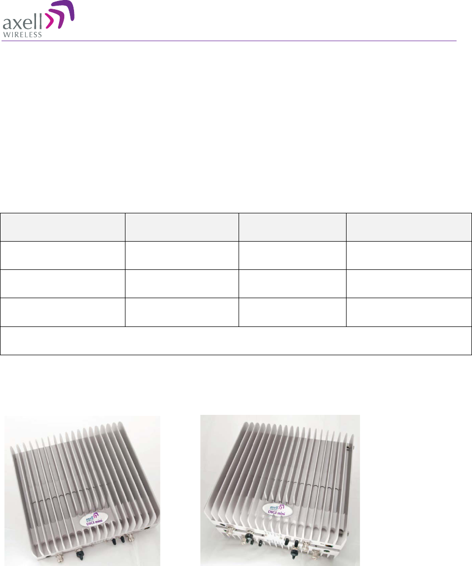
DIGI mini 4 bands Accessory upgrade kit D-MINI 4B-AK
Single Band/Dual Band
Tri Band/Quad Band
AXELL DIGIMINI- AMERICAS REPEATER
PRODUCT DESCRIPTION AND USER’S MANUAL
II DIGImini Americas User Manual Rev 3.5 © Axell Wireless Ltd
Copyright © 2012 Axell Wireless Ltd
All rights reserved.
No part of this document may be copied, distributed, transmitted, transcribed, stored in a retrieval system, or
translated into any human or computer language without the prior written permission of Axell Wireless Ltd.
The manufacturer has made every effort to ensure that the instructions contained in this document are
adequate and free of errors and omissions. The manufacturer will, if necessary, explain issues which may not
be covered by this document. The manufacturer's liability for any errors in the document is limited to the
correction of errors and the aforementioned advisory services.
This document has been prepared to be used by professional and properly trained personnel, and the
customer assumes full responsibility when using them. The manufacturer welcomes customer comments as
part of the process of continual development and improvement of the documentation in the best way possible
from the user's viewpoint. Please submit your comments to the nearest Axell Wireless sales representative.
Contact Information
Headquarters
Axell Wireless
Aerial House
Asheridge Road
Chesham
Buckinghamshire HP5 2QD
United Kingdom
Tel: +44 1494 777000
Fax: +44 1494 777002
Commercial inquiries
info@axellwireless.com
Web site
www.axellwireless.com
Support issues
support@axellwireless.com
Technical Support Line, English speaking
+44 1494 777 747
Contact information for Axell Wireless offices in other countries can be found on our web site,
www.axellwireless.com

AXELL DIGIMINI- AMERICAS REPEATER
PRODUCT DESCRIPTION AND USER’S MANUAL
© Axell Wireless Ltd DIGImini Americas User Manual Rev 3.5 III
About This Manual
This Product Manual provides the following information:
• Description of the DIGImini Repeater
• Procedures for setup, configuration and checking the proper operation of the Mini-Repeater
• Maintenance and troubleshooting procedures
For whom it is Intended
This Product Manual is intended for experienced technicians and engineers. It is assumed that the
customers installing, operating, and maintaining Axell Wireless Mini-Repeaters are familiar with the
basic functionality of Repeaters.
Notice
Confidential - Authorized Customer Use
This document may be used in its complete form only and is solely for the use of Axell Wireless
employees and authorized Axell Wireless channels or customers. The material herein is proprietary to
Axell Wireless. Any unauthorized reproduction, use or disclosure of any part thereof is strictly
prohibited.
All trademarks and registered trademarks are the property of their respective owners.
Disclaimer of Liability
Contents herein are current as of the date of publication. Axell Wireless reserves the right to change
the contents without prior notice. The information furnished by Axell Wireless in this document is
believed to be accurate and reliable. However, Axell Wireless assumes no responsibility for its use.
In no event shall Axell Wireless be liable for any damage resulting from loss of data, loss of use, or
loss of profits and Axell Wireless further disclaims any and all liability for indirect, incidental,
special, consequential or other similes damages. This disclaimer of liability applies to all products,
publications and services during and after the warranty period.
Guarantees
• All antennas must be installed with lightning protection. Damage to power modules, as a
result of lightning are not covered by the warranty.
• Antennas must be connected before switching on AC or DC power. Switching power on
prior to the connection of antenna cables is regarded as faulty installation procedure and therefore
not covered by the Axell Wireless warranty.
Exclusive Remedies
• The remedies provided herein are the Buyer’s sole and exclusive remedies. Axell Wireless shall
not be viable for any direct, incidental, or consequential damages, whether based on contract,
tort, or any legal theory.

AXELL DIGIMINI- AMERICAS REPEATER
PRODUCT DESCRIPTION AND USER’S MANUAL
IV DIGImini Americas User Manual Rev 3.5 © Axell Wireless Ltd
Compliance with FCC
FCC Part 15
This device complies with part 15 of the FCC Rules. Operation is subject to the following two
conditions:
1. This device may not cause harmful interference, and
2. This device must accept any interference received, including interference that may cause undesired
operation.
If not installed and used in accordance with the instructions, this equipment generates, uses and can
radiate radio frequency energy. However, there is no guarantee that interference will not occur in a
particular installation. If this equipment does cause harmful interference to RF reception, which can
be determined by turning the equipment off and on, the user is encouraged to try to correct the
interference by one or more of the following measures:
• Reorient or relocate the Donor antenna.
• Increase the separation between the equipment and receiver.
• Connect the equipment into an outlet on a circuit different from that to which the receiver is
connected.
Unauthorized Changes to Equipment
Changes or Modifications not expressly approved by the manufacturer responsible for compliance
could void the user’s authority to operate the equipment
FCC RF Exposure Limits
This unit complies with FCC RF exposure limits for an uncontrolled environment. This equipment
must be installed and operated with a minimum distance of 20cm between the radiator and any
person’s body.
Antenna Installation
Installation of an antenna must comply with the FCC RF exposure requirements. The antenna used
for this transmitter must be mounted on outdoor or indoor permanent structures.
The maximum antenna gain for indoor operation is 2.2 dBi and for the external antenna is 13dBi
(except for 1700MHz – where the maximum antenna gain for external operation is 9 dBi). Cable loss
of at least 2dB is taken into account for all cases.
Antennas having a gain greater than these are strictly prohibited for use with this device. In indoor
applications the antenna must be installed at a minimum separation distance of 20cm from all nearby
persons.

AXELL DIGIMINI- AMERICAS REPEATER
PRODUCT DESCRIPTION AND USER’S MANUAL
© Axell Wireless Ltd DIGImini Americas User Manual Rev 3.5 V
Compliance with IC
Under Industry Canada regulations, this radio transmitter may only operate using an antenna of a type
and maximum (or lesser) gain approved for the transmitter by Industry Canada. To reduce potential
radio interference to other users, the antenna type and its gain should be so chosen that the equivalent
isotropically radiated power (e.i.r.p.) is not more than that necessary for successful communication.
Conformément à la réglementation d'Industrie Canada, le présent émetteur radio peut fonctionner
avec une antenne d'un type et d'un gain maximal (ou inférieur) approuvé pour l'émetteur par
Industrie Canada. Dans le but de réduire les risques de brouillage radioélectrique à l'intention des
autres utilisateurs, il faut choisir le type d'antenne et son gain de sorte que la puissance isotrope
rayonnée équivalente (p.i.r.e.) ne dépasse pas l'intensité nécessaire à l'établissement d'une
communication satisfaisante.
AXELL DIGIMINI- AMERICAS REPEATER
PRODUCT DESCRIPTION AND USER’S MANUAL
VI DIGImini Americas User Manual Rev 3.5 © Axell Wireless Ltd
General Safety Warnings Concerning Use of This System
Always observe standard safety precautions during installation, operation and maintenance of this
product.
Caution labels!
Throughout this manual, there are "Caution" warnings. "Caution" calls
attention to a procedure or practice, which, if ignored, may result in injury
or damage to the system, system component or even the user. Do not
perform any procedure preceded by a "Caution" until the described
conditions are fully understood and met.
Danger: Electrical
Shock
To prevent electrical shock when installing or modifying the system
power wiring, disconnect the wiring at the power source before working
with un insulated wires or terminals.
Caution: Safety to
personnel
Before installing or replacing any of the equipment, the entire manual
should be read and understood.
The user needs to supply the appropriate AC or DC power to the repeater.
Incorrect power settings can damage the repeater and may cause injury to
the user.
Please be aware that the equipment may, during certain conditions
become very warm and can cause minor injuries if handled without any
protection, such as gloves.
Caution: Safety to
equipment
When installing, replacing or using this product, observe all safety
precautions during handling and operation. Failure to comply with the
following general safety precautions and with specific precautions
described elsewhere in this manual violates the safety standards of the
design, manufacture, and intended use of this product.
Changes or modifications not expressly approved by the party responsible
for compliance could void the user’s authority to operate the equipment
Axell Wireless assumes no liability for the customer's failure to comply
with these precautions. This entire manual should be read and understood
before operating or maintaining the repeater.
Warning: Restricted
Access Location
Access to the Axell unit installation location is restricted to SERVICE
PERSONNEL and to USERS who have been instructed on the restrictions
and the required precautions to be taken.
Attention:
Electrostatic
Sensitivity
Observe electrostatic precautionary procedures.
ESD = Electrostatic Discharge Sensitive Device.
Static electricity can be conducted to the semiconductor chip from the
centre pin of the RF input connector, and through the AC connector pins.
When unpacking and otherwise handling the repeater, follow ESD
precautionary procedures including use of grounded wrist straps,
grounded workbench surfaces, and grounded floor mats.

AXELL DIGIMINI- AMERICAS REPEATER
PRODUCT DESCRIPTION AND USER’S MANUAL
© Axell Wireless Ltd DIGImini Americas User Manual Rev 3.4 VII
Table of Contents
1 Introduction 1
1.1 Features and Capabilities .................................................................................................... 2
1.2 Models and Ordering Information ...................................................................................... 3
1.3 Dual-band and Quad-band Installations ............................................................................ 3
1.4 Smart-ALC Function ............................................................................................................ 3
1.5 DMCU - Optional ................................................................................................................... 4
1.6 DIGImini Interfaces .............................................................................................................. 4
1.6.1 Front Panel Interfaces ............................................................................................... 5
1.6.2 Side Panel Interfaces ................................................................................................ 6
1.7 DIGImini Power Supply ........................................................................................................ 6
2 Antenna and Repeater Installation Requirements 7
2.1 Base (Donor) Antenna Requirements ................................................................................ 7
2.1.1 Required Antenna Information .................................................................................. 7
2.1.2 Donor Antenna specifications .................................................................................... 7
2.1.3 Installation Criteria ..................................................................................................... 8
2.2 Service Antenna Requirements .......................................................................................... 8
2.2.1 Required Antenna Information .................................................................................. 8
2.2.2 Recommended Antennas .......................................................................................... 8
2.2.3 Mobile (Service) Antenna Installation Criteria ........................................................... 9
2.3 Repeater Pre-Installation Requirements ............................................................................ 9
2.3.1 Safety Guidelines ...................................................................................................... 9
2.3.2 Required BTS Information ......................................................................................... 9
2.3.3 Criteria for Repeater Installation Location ............................................................... 10
2.3.4 RF Cable Installation Guidelines ............................................................................. 10
3 Dual-Band Repeater Installation 11
3.1 Single Unit Installation ...................................................................................................... 11
3.1.1 Overview .................................................................................................................. 11
3.1.2 Required Tools and Materials ................................................................................. 11
3.1.3 DIGImini Dual-band Kit ............................................................................................ 12
3.1.4 Mounting Repeater .................................................................................................. 13
3.1.5 Before Connecting the Antennas or Power ............................................................. 16
3.1.6 Antenna Connections .............................................................................................. 17
3.1.7 Power Up ................................................................................................................. 18
3.1.8 What Next? .............................................................................................................. 18
4 Two Dual Units (Quad-band) Installation 19
4.1 Overview ............................................................................................................................. 19
4.2 View of the Quad Band Installation .................................................................................. 20
4.3 Required Tools and Materials ........................................................................................... 21
4.4 DIGImini Tri/Quad-band Kit ............................................................................................... 21
4.4.1 Top Layer Items....................................................................................................... 21
4.4.2 Middle layer Items ................................................................................................... 22
4.4.3 Bottom Layer Items ................................................................................................. 22
4.4.4 Additional Items ....................................................................................................... 23
4.5 Upgrading to a Quad-Band System.................................................................................. 23
4.5.1 Assemble the DIGImini Units .................................................................................. 23
4.5.2 Assembling Quad-Band Plates and Labels ............................................................. 28
4.5.3 Connect SMA Jumper Cables ................................................................................. 30
4.5.4 Before Connecting the Antennas or Power ............................................................. 33

AXELL DIGIMINI- AMERICAS REPEATER
PRODUCT DESCRIPTION AND USER’S MANUAL
VIII DIGImini Americas User Manual Rev 3.5 © Axell Wireless Ltd
4.5.5 Antenna Connections .............................................................................................. 33
4.5.6 Power Up ................................................................................................................. 34
4.5.7 What Next? .............................................................................................................. 34
5 Setup and Configuration 35
5.1 Open a Direct Local WEB Session to the Repeater ........................................................ 35
5.2 Navigating the Web GUI Application ................................................................................ 37
5.2.1 Band Pane and Tabs ............................................................................................... 38
5.2.2 Operation Buttons.................................................................................................... 38
5.2.3 Signal Levels and Channel Configuration ............................................................... 39
5.2.4 RF Gain Setting Criteria .......................................................................................... 39
5.2.5 Bandwidth and the Number of Available Bands ...................................................... 39
5.2.6 Adjusting the Signal Levels and Configuring Channels .......................................... 40
5.3 Monitoring and Troubleshooting ...................................................................................... 44
5.3.1 Repeater Alarms and Troubleshooting.................................................................... 44
5.3.2 DIGImini LED Troubleshooting ................................................................................ 45
6 DMCU Installation and Management 46
6.1 Features and Capabilities .................................................................................................. 47
6.2 DMCU Interfaces ................................................................................................................. 47
6.3 DMCU Kit ............................................................................................................................. 48
6.4 DMCU Installation Procedure ............................................................................................ 48
6.4.1 GPRS Modem ......................................................................................................... 48
6.4.2 CDMA Modem ......................................................................................................... 48
6.4.3 SIM Card Installation (GSM/GPRS Modems only) .................................................. 49
6.4.4 Connecting the DMCU to the Repeater................................................................... 50
6.4.5 DMCU Dry Contacts ................................................................................................ 51
6.5 Opening a Web Session via the DMCU ............................................................................ 52
6.5.1 Login to the Repeater .............................................................................................. 55
6.5.2 Navigating the Web GUI Application ....................................................................... 56
6.6 Basic Configuration Procedures ...................................................................................... 58
6.6.1 Configuring Signal Levels and Channels ................................................................ 58
6.6.2 Setting Date and Time ............................................................................................. 58
6.6.3 Configuring the External Alarms .............................................................................. 59
6.7 Communication and System Parameters ........................................................................ 60
6.7.1 The Communication Configuration Tab .................................................................. 60
6.7.2 IP Address Configuration ........................................................................................ 60
6.7.3 General Modem Parameters ................................................................................... 61
6.7.4 GSM/GPRS Modem Setup ...................................................................................... 63
6.7.5 CDMA Modem Setup............................................................................................... 64
6.7.6 Verifying Modem RSSI and Registration ................................................................. 66
6.7.7 Direct Circuit Switch Connection ............................................................................. 66
6.7.8 Configuring Notification Method - SNMP Trap or SMS ........................................... 67
6.8 DMCU Administration ........................................................................................................ 70
6.8.1 Viewing Repeater Level Information ....................................................................... 70
6.8.2 CMU Software Upgrade .......................................................................................... 71
6.8.3 Backup/Restore of Repeater Configuration ............................................................ 72
6.8.4 User Management ................................................................................................... 74
6.9 CMU Monitoring and Troubleshooting Options .............................................................. 76
6.9.1 DMCU LED Troubleshooting ................................................................................... 76
6.9.2 Viewing the Alarms Log ........................................................................................... 77
6.9.3 Viewing External Alarms Log .................................................................................. 78
Appendix A: Specifications (@+25°C) 79
AXELL DIGIMINI- AMERICAS REPEATER
PRODUCT DESCRIPTION AND USER’S MANUAL
© Axell Wireless Ltd DIGImini Americas User Manual Rev 3.5 1
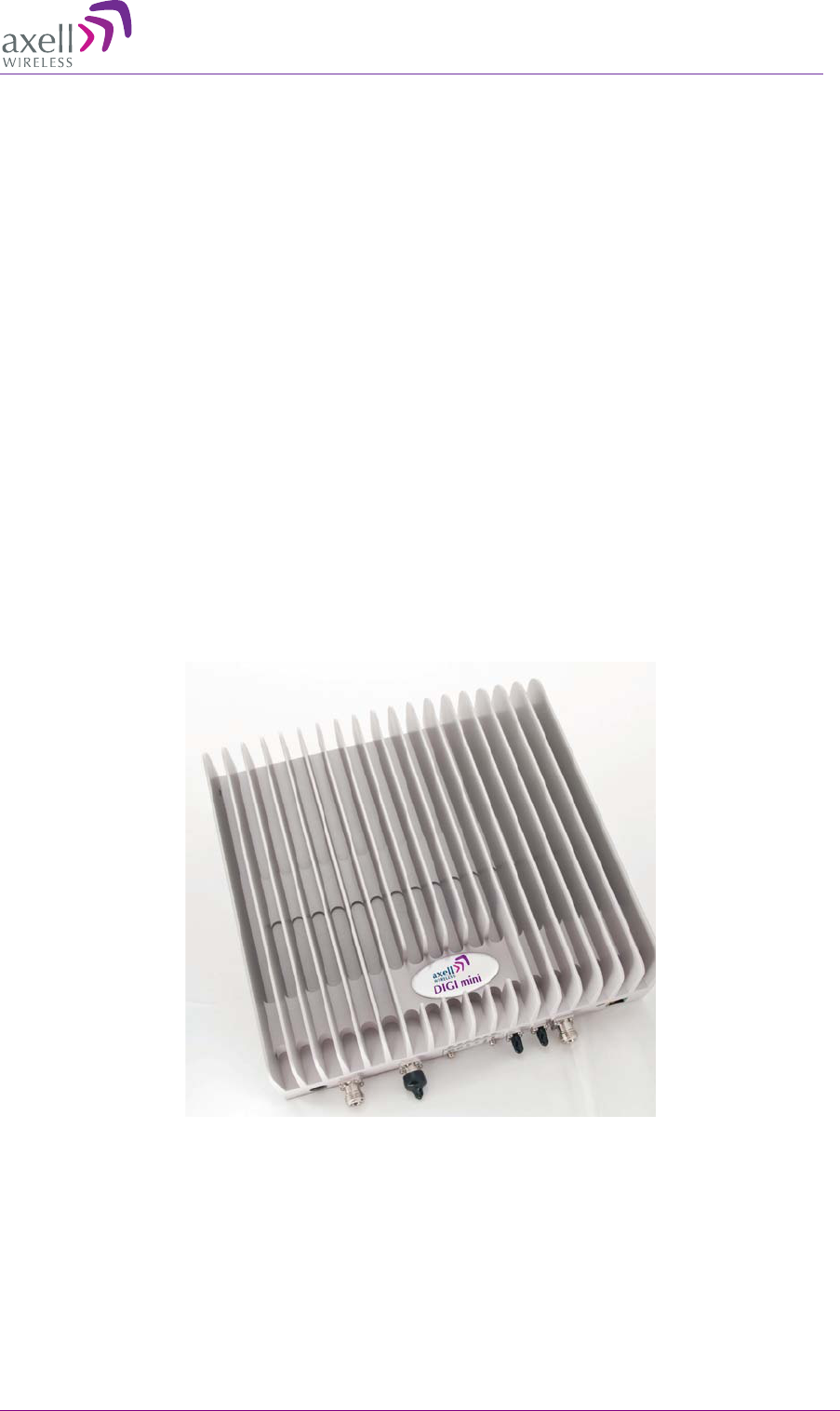
1 Introduction
Axell Wireless DIGImini (digital mini) is a scalable in-building mini-repeater with advanced digital
filtering capabilities. Each repeater supports two bands where two repeaters can be easily cascaded
into a compact assembly to provide tri-band and quad-band solutions.
For each band, the user can configure up to six non-contiguous sub-bands, where the gain and power
of each of the sub-bands can be individually defined. The Repeater provides highly accurate out-of-
band-rejection and simple, GUI based procedures for adjusting the pass band according to the
relevant frequency spectrums.
DIGImini includes the SmartALC power control algorithm that automatically optimizes the gain
setting by learning the actual range of RSSI levels over a user-specified period of time. The
SmartALC algorithm prevents oscillations, reduces the amount of isolation required by the system
and optimizes the system to minimize noise rise at the donor cell site.
A state-of-the-art Interference Mitigation and Oscillation Prevention (IMOP) is used to measure the
isolation between the antennas and gain is reduced immediately to prevent oscillation. Local Web
based management is available via an RJ45 connection.
Optional, complete, remote Web-based management via a GPRS/CDMA modem provided by the
DIGImini Control Unit (DMCU). The DMCU is ordered separately, where a single DMCU can
support a single DIGImini or two cascaded units.
Figure 1-1. Axell DIGImini Repeater

AXELL DIGIMINI- AMERICAS REPEATER
PRODUCT DESCRIPTION AND USER’S MANUAL
2 DIGImini Americas User Manual Rev 3.5 © Axell Wireless Ltd
1.1 Features and Capabilities
• Supported bands and (composite) output power at antenna port (model dependent):
• 700U or 700L MHz and 1700
• 850 MHz and 1900 MHz
• Output power at the antenna (composite):
• 700UMHz, 700LMHz and 850MHz: 21dBm
• 1700MHz and 1900MHz: 20dBm
• Maximum RF Gain: 73 dB
• Up to six software selectable non-contiguous sub-bands per 2 bands (see sec. 5.2.5 for details)
can be configured with highly accurate frequency selection and dedicated gain and power settings
• SmartALC™ technology per sub-band:
• Automatically sets optimum gain
• Prevents oscillations and balances coverage
• Ensures transparent network operation
• Supports multi-operator functionality
• Lightweight and compact footprint for easy installation
• Multi-functional capabilities and modular design
• Continuously monitors and adapts to the RF environment via Auto gain feature
• Easy commissioning and setup via web-based browser
• Variable bandwidth settings from 200KHz to 25 MHz
• LEDs for local alarm indicators
• Optional DIGImini Control Unit (DMCU) – provides complete remote control and monitoring
capabilities over GPRS/CDMA (model dependant):
• Remote control via SMS
• Remote alarming through SNMP alarm traps

AXELL DIGIMINI- AMERICAS REPEATER
PRODUCT DESCRIPTION AND USER’S MANUAL
© Axell Wireless Ltd DIGImini Americas User Manual Rev 3.5 3
1.2 Models and Ordering Information
The following models are available.
ORDERING INFORMATION for Axell DIGImini Americas Repeaters
Identification Description Part Number
DIGI Mini 850/1900 DIGI MINI 850/1900 21/20dBm 6 Filters D-MINI-2108-2019
DIGI Mini 700U/1700 DIGI MINI 700U/1700 21/20dBm 6 Filters D-MINI-2107U-2017
DIGI Mini 700L/1700 DIGI MINI 700L/1700 21/20dBm 6 Filters D-MINI-2107L-2017
DIGI Mini GPRS
Modem External GPRS modem DMCU
DIGI Mini CDMA
Modem External CDMA modem DMCU-CDMA
DIGI Mini Accessory
Kit DIGI MINI 4 bands Accessory upgrade kit D-MINI 4B-AK
1.3 Dual-band and Quad-band Installations
DIGImini can be installed in two configurations: procedures:
• Single DIGImini unit – details in Chapter 3.
• Quad-band assembly consisting of two DIGImini units – details in Chapter 4
1.4 Smart-ALC Function
The Smart Automatic Level Control (Smart-ALC) is an innovative algorithm for automatic repeater
gain adjustment per sub-band.
Combined with advanced control algorithms, SALC is capable of learning the traffic load
characteristics and adjusting the Repeater RF Gain to the desired value.
Smart ALC eliminates the need to perform initial settings for maximal traffic load conditions and on-
site gain adjustments.
Smart-ALC maintains the Uplink/Downlink gain balance for system transparency. In addition, Smart-
ALC prevents oscillations that may occur due to insufficient isolation while maintaining the gain in a
linear range operation by adjusting the repeater paths’ gain accordingly.
IMOP (Isolation Measurement and Oscillation Prevention) algorithm effectively reduces oscillation
problems.
The repeater’s power amplifier includes power-monitoring circuits with Automatic Level Control
(ALC) that prevents excessive output power while maintaining the power amplifier linearity.

AXELL DIGIMINI- AMERICAS REPEATER
PRODUCT DESCRIPTION AND USER’S MANUAL
4 DIGImini Americas User Manual Rev 3.5 © Axell Wireless Ltd
1.5 DMCU - Optional
The DIGImini Control Unit (DMCU) is an optional control unit that is ordered separately. The
DMCU is installed externally, where one unit can support a single DIGImini unit as well as an
upgrade to a DIGImini Quad-band assembly. The DMCU provides complete remote control and
monitoring capabilities over GPRS or CDMA (model dependent), including:
• Remote control via SMS
• Remote alarming through SNMP alarm traps
Refer to Chapter 6 - DMCU Installation and Management for the complete description of the DMCU
and the configuration and management capabilities provided by the unit.
1.6 DIGImini Interfaces
The DIGImini is supplied in two physical configurations: Single unit supporting either one or two
bands; two cascaded units supporting up to four bands. Power supplies dedicated to each unit are
connected externally.
An optional DMCU supporting an external modem is also connected externally, where a single
DMCU can serve two cascaded units.
The interfaces are located on the front and on the side panels.
AXELL DIGIMINI- AMERICAS REPEATER
PRODUCT DESCRIPTION AND USER’S MANUAL
© Axell Wireless Ltd DIGImini Americas User Manual Rev 3.5 5
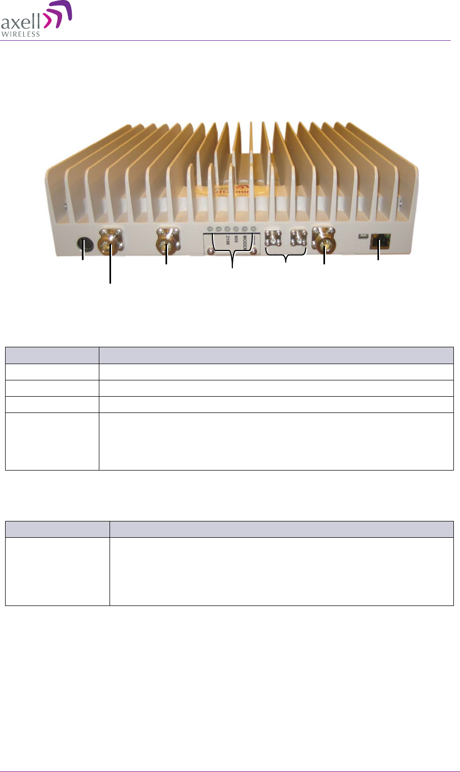
1.6.1 Front Panel Interfaces
The image below shows the unit (the wallmount bracket is not shown).
Figure 1-2: DIGImini Single/Dual-Band Front Panel
The following table provides a description of the front panel connectors.
Port Description
MOBILE Service antenna connections.
BASE Donor antenna connections.
DC Power (12V) Circular, 4-PIN.
RJ 45 Local management and setup port – to be used only if DMCU is not
installed.
ATTENTION! This port is only for local access. Do not connect this
port to your network. It may affect your network!
*Connectors not in use and no termination is required.
The following table provides a description of the front panel LED indicators (See 5.3.2 for more
info.).
LED Description
Band specific LED
(e.g. 850, 1900, etc) Downlink path status and RSSI indication:
• Steady Green – Normal operation
• Orange – Major malfunction
• Red – Blinking panel mask
Status LEDs
N/A*
Power
Mobile
N/A*
Base
ETH
RJ45
AXELL DIGIMINI- AMERICAS REPEATER
PRODUCT DESCRIPTION AND USER’S MANUAL
6 DIGImini Americas User Manual Rev 3.5 © Axell Wireless Ltd
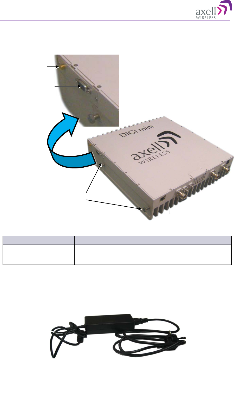
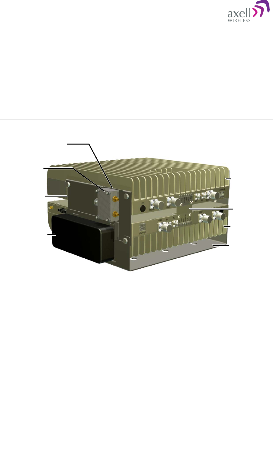
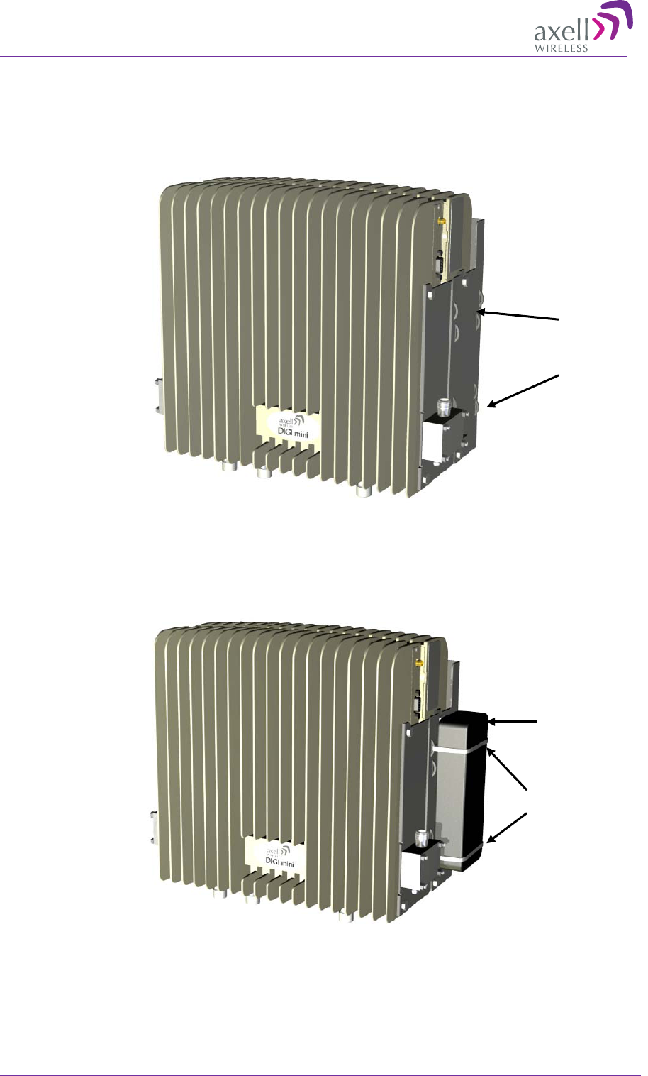
1.6.2 Side Panel Interfaces
The DIGImini side panel supports the DMCU interfaces and the side bolts used for hanging the unit
on the wall bracket.
Figure 1-3. DIGImini Side Panel
Side Connector Description
Modem Modem Antenna connection - relevant if a DMCU is available.
RS485 RS485 connection to DMCU option.
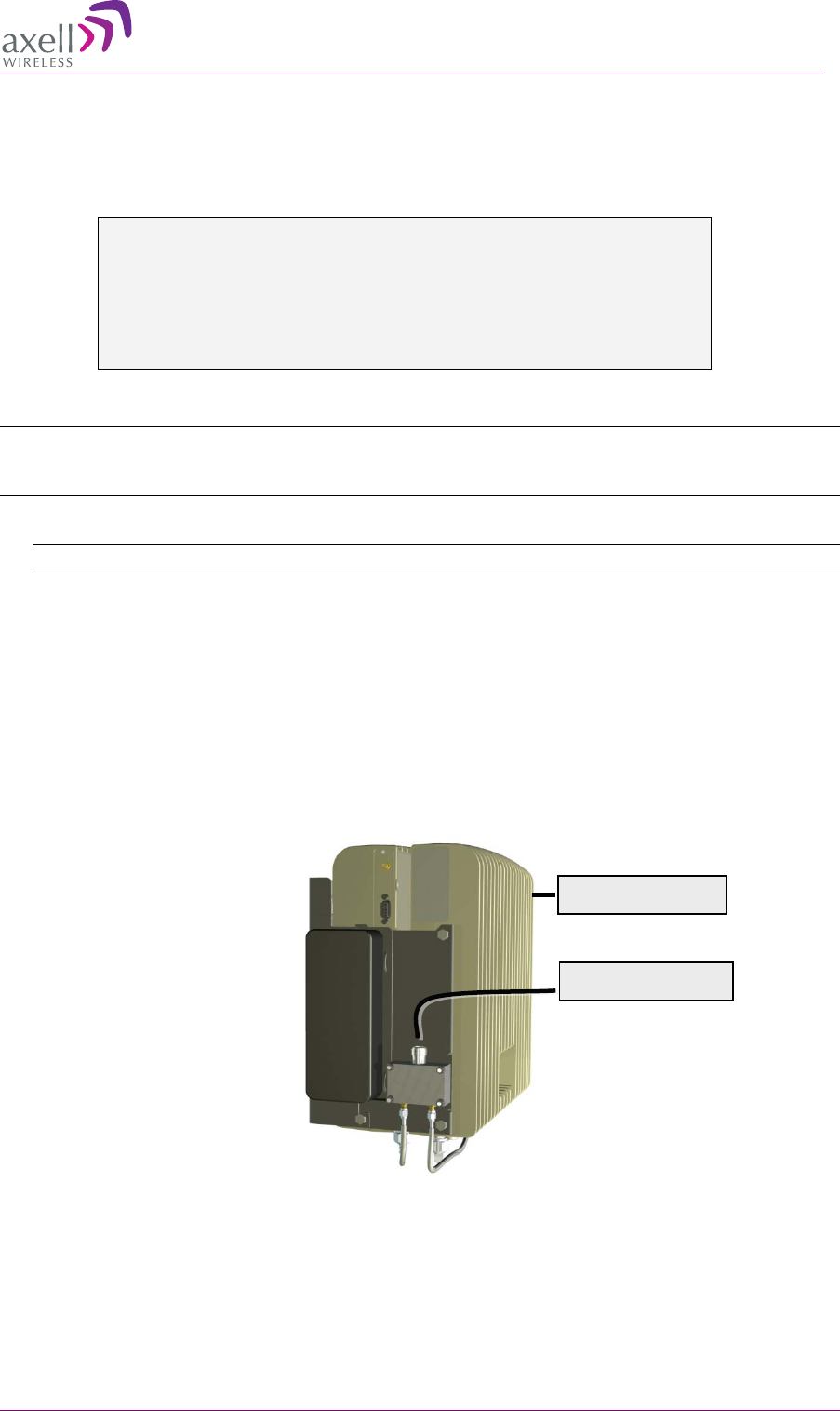
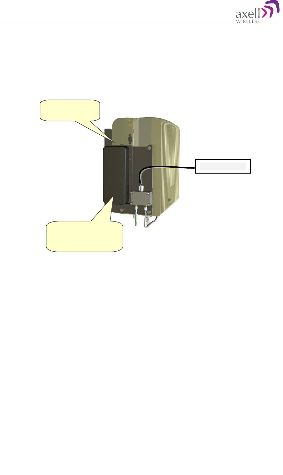
1.7 DIGImini Power Supply
The power supply requires assembly only during an upgrade procedure from a single-band or dual-
band to a triple-band or quad-band solutions in which two DIGImini units are cascaded. Otherwise, it
is preassembled.
Figure 1-4: Repeater Power Supply
Connect to
110/240 VAC
power source
Connect to Front
panel DC power
(12V) connector
Side bolts for hanging
the Repeater on the wall
bracket (x2 on each side)
DMCU Antenna
connection
DMCU RS485
connection

AXELL DIGIMINI- AMERICAS REPEATER
PRODUCT DESCRIPTION AND USER’S MANUAL
© Axell Wireless Ltd DIGImini Americas User Manual Rev 3.5 7
2 Antenna and Repeater Installation
Requirements
This chapter provides information on the specifications of the donor and service antennas suitable for
operation with this repeater, on the installation requirements of the antennas and on the Repeater
installation site and cable requirements.
ATTENTION!!
The DIGImini models described in this manual have been approved by Industry Canada to operate
with the antenna types listed below with the maximum permissible gain and required antenna
impedance for each antenna type indicated. Antenna types not included in this list, having a gain
greater than the maximum gain indicated for that type, are strictly prohibited for use with this device.
Le présent émetteur radio (identifier le dispositif par son numéro de certification ou son numéro de
modèle s'il fait partie du matériel de catégorie I) a été approuvé par Industrie Canada pour
fonctionner avec les types d'antenne énumérés ci-dessous et ayant un gain admissible maximal et
l'impédance requise pour chaque type d'antenne. Les types d'antenne non inclus dans cette liste, ou
dont le gain est supérieur au gain maximal indiqué, sont strictement interdits pour l'exploitation de
l'émetteur.
2.1 Base (Donor) Antenna Requirements
The Base (Donor) antenna is usually installed outdoors and is either a directional antenna such as a
Yagi or a Panel antenna.
2.1.1 Required Antenna Information
You will require the following antenna information
• Antenna type and characteristics
• Height
• Length and type of coaxial cable required for connecting the Donor antenna to the Repeater and
the attenuation.
2.1.2 Donor Antenna specifications
• Yagi type or similar: 8 to 13 dBi gain, except for 1700MHz – where the maximum antenna gain
is 9 dBi.
• Very sharp beam pointed to the BTS..
• Cable and jumper loss is at least 2dB.
• Example of antenna's typical specifications:
Gain: 8 dBd (=10.1 dBi)
VSWR: < 1:5:1
Impedance: 50 ohm

AXELL DIGIMINI- AMERICAS REPEATER
PRODUCT DESCRIPTION AND USER’S MANUAL
8 DIGImini Americas User Manual Rev 3.5 © Axell Wireless Ltd
2.1.3 Installation Criteria
Installation requirements:
• Select a location for the Donor antenna and verify that there is enough signal strength at that
location.
• Install the Donor Antenna at the designated height.
• The antenna should point to the direction of the base station for maximum input power.
• Verify that the antenna is in the base stations line of sight (raise the antenna if necessary).
• Install the donor antenna at a higher level (i.e. floor) than the mobile antenna.
• Must be installed at a minimum distance of 20cm from any personnel within the area.
2.2 Service Antenna Requirements
The Service antenna is installed indoors, where the type of antenna depends on the application.
2.2.1 Required Antenna Information
The following antenna requirements, specifications and site considerations should be met.
• Service area type and size
• Antenna type and characteristics
• Height
• Length and type of coaxial cable required for connecting the antenna to the Repeater and the
attenuation.
2.2.2 Recommended Antennas
• One or a combination of the following antennas can be used: Ceiling Mount Patch antenna, Wall
Mount Patch antenna, Corner Reflector.
• Choose an antenna with high side lobe attenuation which enables maximum isolation from the
service/ mobile antenna.
• Maximum antenna gain for indoor operation 2.2dBi

AXELL DIGIMINI- AMERICAS REPEATER
PRODUCT DESCRIPTION AND USER’S MANUAL
© Axell Wireless Ltd DIGImini Americas User Manual Rev 3.5 9
2.2.3 Mobile (Service) Antenna Installation Criteria
Determine the antenna installation configuration, according to the transmission requirements and the
installation site conditions.
Installation requirements:
• An indoor antenna should be installed at a convenient location. It should be free of metallic
obstruction.
• Install the Service Antenna at the designated height and tune it roughly toward the Service
coverage area.
• Installation of this antenna must provide a minimum separation distance of 20cm from any
personnel within the area.
2.3 Repeater Pre-Installation Requirements
2.3.1 Safety Guidelines
Before installing the Repeater, review the following safety information:
• Follow all local safety regulations when installing the Repeater.
• Only qualified personnel are authorized to install and maintain the Repeater.
• Ground the Repeater with the grounding bolt located on the external lower side of the Repeater).
• Do not use the grounding bolt to connect external devices.
• Follow Electro-Static Discharge (ESD) precautions.
• Use low loss cables to connect the antennas to the Repeater.
2.3.2 Required BTS Information
Required BTS Information
• BTS channels
• BTS output power per channel
• BTS antenna gain
• BTS antenna height
• Distance from Repeater site to BTS

AXELL DIGIMINI- AMERICAS REPEATER
PRODUCT DESCRIPTION AND USER’S MANUAL
10 DIGImini Americas User Manual Rev 3.5 © Axell Wireless Ltd
2.3.3 Criteria for Repeater Installation Location
The following criteria should be considered when selecting the Repeater installation site location:
• Application type
• General surroundings
• Available installation
• Install the Repeater in a shielded, ventilated, and easy-to-reach area.
• Verify that there is a minimum of a 50 cm (20”) radius of space around the Repeater, enabling
easy access to the repeater for maintenance and on-site inspection.
• Distance from antenna site - It is recommended that the installation location be as close as
possible to the antenna site in order to maintain the cable loss to a minimum.
• The Repeater is convection cooled so airflow and alternation should be possible.
• Follow Electro-Static Discharge (ESD) precautions.
• Install the Repeater close to the service area to monitor the output power.
• Use low loss cables to connect the antennas to the Repeater.
2.3.4 RF Cable Installation Guidelines
Required:
• For all coaxial connections to/from the Repeater - high performance, flexible, low loss 50Ω
coaxial communications cable.
• All cables shall be weather-resistant type.
• Cable length - determined by the Repeater installation plan. When calculating the cable length,
take into account excess cable slack so as not to limit the insertion paths.

AXELL DIGIMINI- AMERICAS REPEATER
PRODUCT DESCRIPTION AND USER’S MANUAL
© Axell Wireless Ltd DIGImini Americas User Manual Rev 3.5 11
3 Dual-Band Repeater Installation
This section describes two types of installation procedures:
• Single DIGImini unit – section 3.1
• Quad-band assembly consisting of two DIGImini units – section 1 4.
3.1 Single Unit Installation
3.1.1 Overview
NOTE: The Donor and Mobile antennas can be positioned and installed (without being connected
to the Repeater) at any time either before or after mounting and grounding the Repeater.
1. Unpack the Repeater kit.
2. Mount the Bracket on the wall, hang the Repeater and Power Supply on the bracket (do not
connect power).
3. Perform the required isolation and link tests.
4. Connect the antennas.
5. Power-on the Repeater.
6. If a DMCU is available, mount the unit (adjacent to the Repeater, on the wall, and connect to the
Repeater according to the instructions in Chapter 6 - DMCU Installation and Management.
3.1.2 Required Tools and Materials
The following is required in order to install the Repeater:
• Standard professional tool box
• A computer (i.e. laptop for running the setup)
AXELL DIGIMINI- AMERICAS REPEATER
PRODUCT DESCRIPTION AND USER’S MANUAL
12 DIGImini Americas User Manual Rev 3.5 © Axell Wireless Ltd
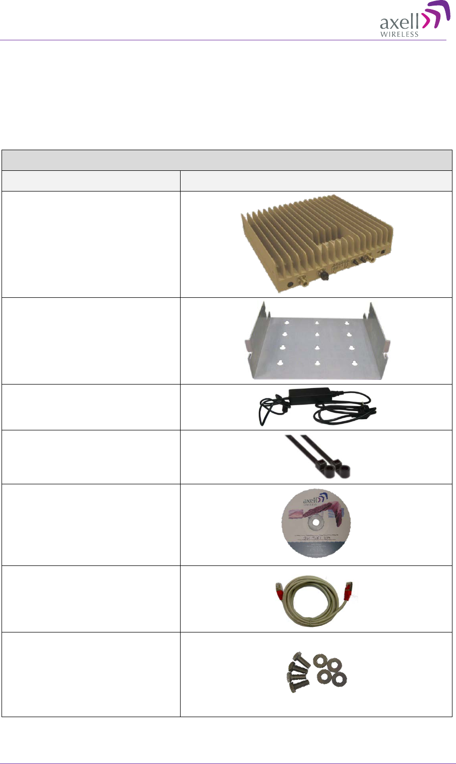
3.1.3 DIGImini Dual-band Kit
Upon receiving the Repeater, perform the following:
1. Examine the shipping container for damage before unpacking the unit.
2. Perform a visual inspection to reveal any physical damage to the equipment.
3. Verify that all of the equipment (listed below) is included. Otherwise contact Axell Wireless.
DIGImini Repeater Kit
Description Image
DIGImini Repeater
Wallmount Bracket
Repeater Power Supply (12V)
2 x Ties for securing power supply
CD with documentation
Ethernet Cross-cable
4 x Repeater Mounting Bolts &
Washers
AXELL DIGIMINI- AMERICAS REPEATER
PRODUCT DESCRIPTION AND USER’S MANUAL
© Axell Wireless Ltd DIGImini Americas User Manual Rev 3.5 13
3.1.4 Mounting Repeater
Choose the location of the Repeater on the wall according to the following criteria:
• The location should be at normal eye level height, above ground.
• Be sure to allow easy access to the Repeater for maintenance and on-site inspection.
WARNING!!! THE REPEATER MUST ALWAYS BE INSTALLED VERTICALLY AND
TOP-DOWN, TO ALLOW FREE-FLOW OF COOLING AIR. HORIZONTAL
INSTALLATION ON A BENCH FOR PROLONGED PERIOD OF TIME MAY CAUSE
DAMAGE TO THE REPEATER DUE TO OVER-HEATING
To mount the Repeater on the wall
1. Using the bracket for reference to the bolt locations, insert the appropriate bolts (not supplied) on
the wall, according to the type of wall.
2. Hang the bracket on the wall.
Figure 3-1. Mounting the Bracket on the Wall
Location of assembly
holes
Location of assembly
holes
AXELL DIGIMINI- AMERICAS REPEATER
PRODUCT DESCRIPTION AND USER’S MANUAL
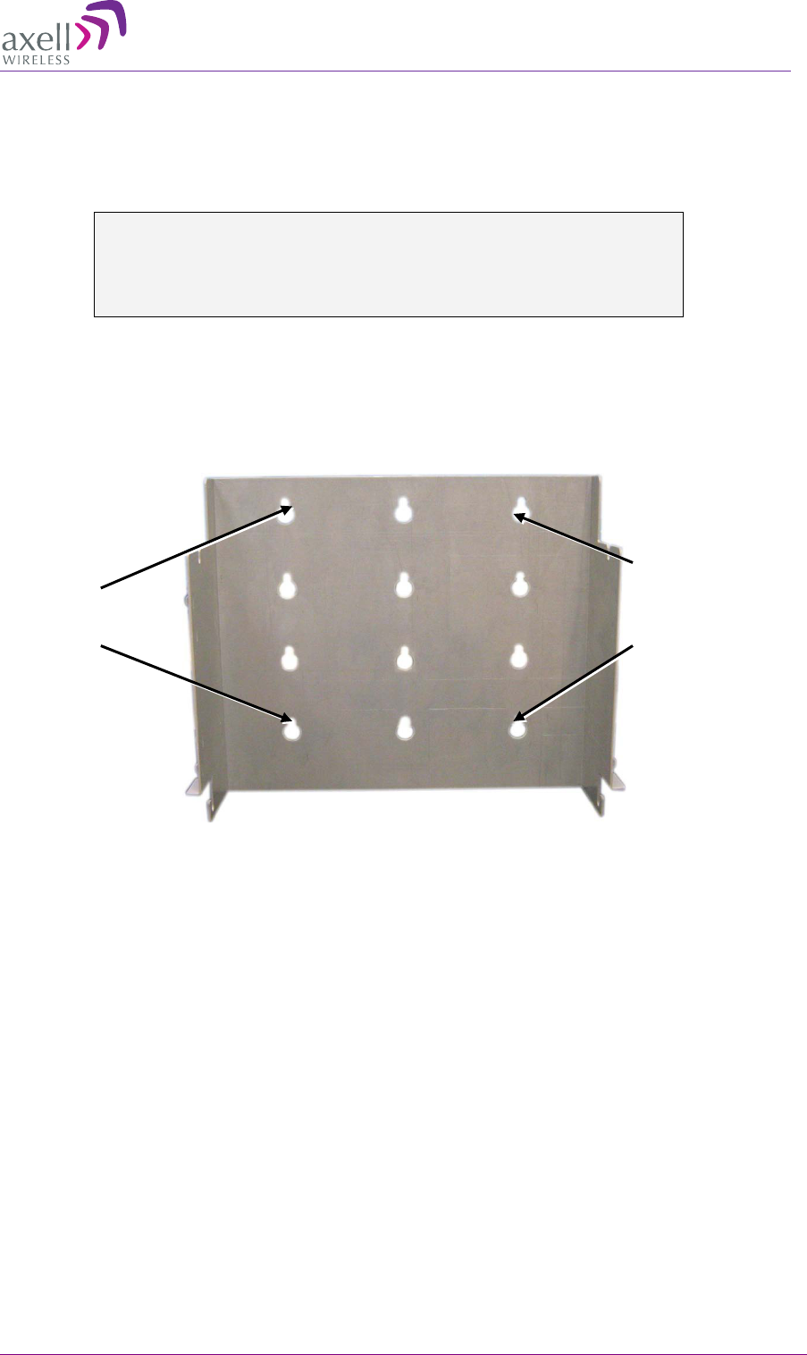
14 DIGImini Americas User Manual Rev 3.5 © Axell Wireless Ltd
The bracket provides two main capabilites:
• Four slots (two bottom and two top) on which to hang the Repeater.
• A step and loops on each side of the bracket for securing the power supply (on any of the
sides).
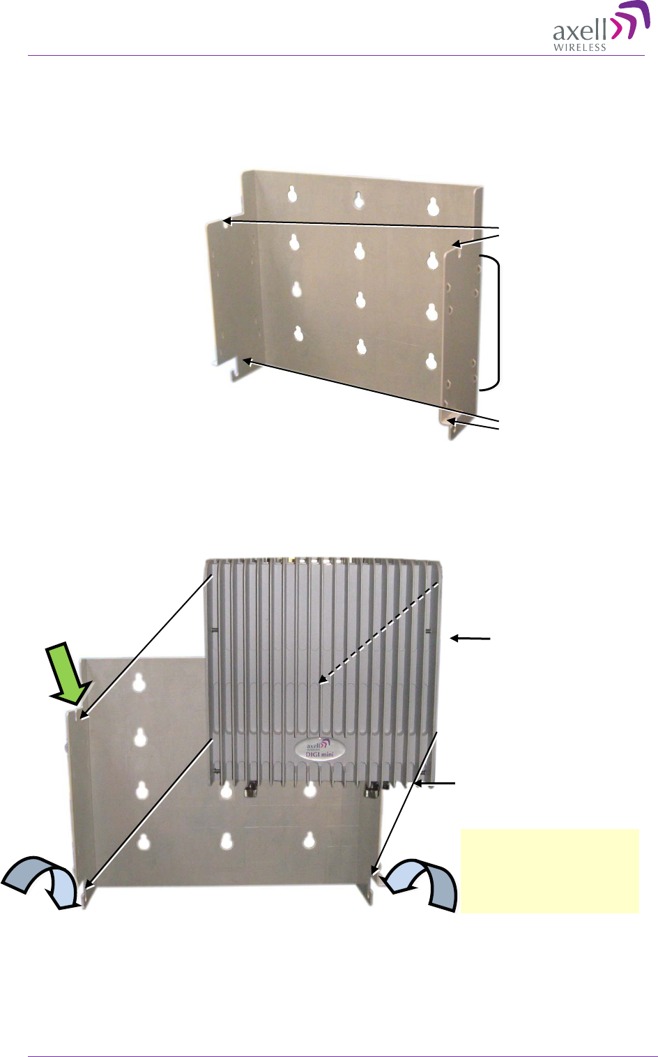
Figure 3-2. Bracket description
3. Hang the Repeater on the Bracket, ridges facing outwards as illustrated below. Use repeater
(four) SIDE screws to hang the Repeater securely on the bracket side slots
Figure 3-3. DIGImini to Bracket Mounting
Connectors down
Top slots for
hanging
Bottom slots
for hanging
Mounting and
securing P.S.
(on either side)
Heatsink ridges
facing Outward
Fit two BOTTOM Repeater
bolts on bracket slots and
lift UP to slide two TOP
screws into top slots
AXELL DIGIMINI- AMERICAS REPEATER
PRODUCT DESCRIPTION AND USER’S MANUAL
© Axell Wireless Ltd DIGImini Americas User Manual Rev 3.5 15
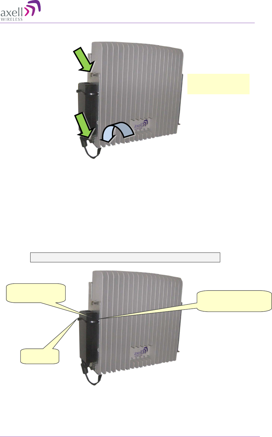
Figure 3-4. Hanging Repeater on Bracket
4. Verify that the Repeater is firmly mounted and tighten the Repeater bolts so it is secured to the
wall mount bracket.
5. To mount the Repeater Power Supply:
• Pass two ties through the loops at the side of the bracket.
• Position the PS on either side of the bracket, firmly on the step and secure the power supply
to the bracket using the ties.
• Trim the ties
WARNING!!! DO NOT CONNECT POWER AT THIS POINT.
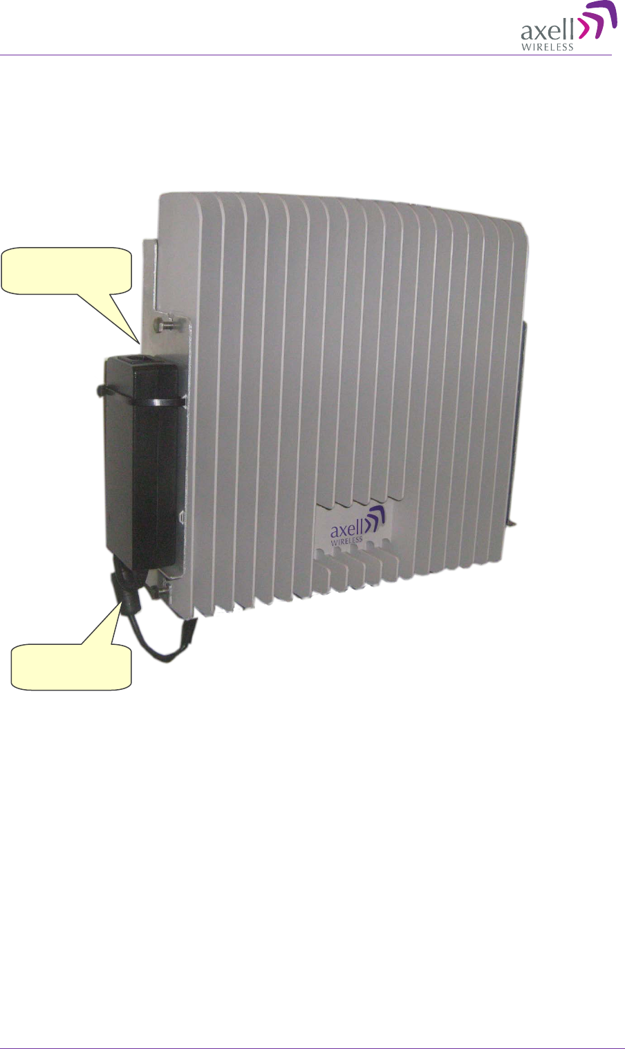
Figure 3-5. Mounting P.S.
2. Position P.S. firmly on
step and secure with ties
1. Pass ties
through loops
Side view of mounted
Repeater
3. Trim ties

AXELL DIGIMINI- AMERICAS REPEATER
PRODUCT DESCRIPTION AND USER’S MANUAL
16 DIGImini Americas User Manual Rev 3.5 © Axell Wireless Ltd
3.1.5 Before Connecting the Antennas or Power
Before connecting the antennas or power perform the following procedures described in this section:
• Verify isolation between the donor and mobile antennas
• Verify link between the BTS and the Repeater
3.1.5.1 Verifying Antenna Isolation between Donor and Mobile Antennas
The isolation between the Base/Donor and Mobile/Service antennas is critical. Lower isolation
can lead to high in-band ripple, oscillations and low signal quality.
The isolation between the Base/Donor and Mobile/Service antennas is critical especially for high
gain, outdoor applications.
• For proper operation of the Repeater, it is recommended that the isolation between the Donor and
Service antennas be at least 10dB higher than the Repeaters set gain.
• Insure proper vertical or horizontal distance separation between Donor and Service antennas
NOTE: Lower isolation can lead to high in-band ripple, oscillations and low signal quality.
To measure the isolation, proceed as follows:
1. Inject a known signal from a signal generator into one antenna (preferably the Donor antenna).
2. Measure the coupled output from the Service antenna, using the Spectrum analyzer and LNA if
applicable.
3. Perform this procedure across the frequency range of both the Uplink and Downlink bands.
4. Register the lower result for system operation.
3.1.5.2 Verifying Link between the BTS and the Repeater
WARNING!
PERFORM THIS PROCEDURE BEFORE CONNECTING THE ANTENNAS TO THE
REPEATER OR POWERING ON THE REPEATER. THE REPEATER SHOULD NOT
BE OPERATED PRIOR TO THE VERIFICATION OF THE OPERATING PARAMETER IN
ITS INSTALLATION ENVIRONMENT.
Before connecting the antennas or powering up the Repeater, verifying the Link
between the BTS and the Repeater
This test checks the signal strength from the BTS antenna to the Repeater.
AXELL DIGIMINI- AMERICAS REPEATER
PRODUCT DESCRIPTION AND USER’S MANUAL
© Axell Wireless Ltd DIGImini Americas User Manual Rev 3.5 17
Proceed as follows:
1. Using a Spectrum analyzer, measure the received signal from BTS at the Donor antenna port near
the Repeater.
2. Adjust the Donor antenna direction to receive the maximum signal strength.
3. Compare the received signal strength with the calculated signal strength from the design phase.
In case of discrepancy, check for one of the following:
• Antenna out of direction
• Antenna tuned to side lobe instead of main lobe
• Antenna connector or antenna cable faulty
• Line-of-sight problem (obstruction), etc.
4. Register the signal strength of the downlink channel for the system operation phase.
3.1.6 Antenna Connections
CAUTION! DO NOT CONNECT THE ANTENNA CABLES TO THE REPEATER
BEFORE VERIFYING THE INSTALLATION PARAMETERS.
CAUTION! DO NOT POWER-UP THE REPEATER WITHOUT EITHER THE
ANTENNAS BEING CONNECTED OR THE ANTENNA CONNECTIONS TERMINATED
WITH DUMMY LOADS.
To connect the antennas to the Repeater
NOTE: If the coaxial cables are NOT weather-resistant type, wrap the exterior coaxial cables with
insulation and holding tape (Type 3M Rubber splicing tape) for environmental protection and to
ensure longer lifetime.
1. Install the antenna cables along their path to the Repeater, and connect them to the Antennas.
NOTE: Be sure to use low loss cables.
2. Connect the Donor antenna to the Repeater BASE port. (Donor antenna specifications and
installation criteria are described in section 2.1).
3. Connect the Service antenna to the Repeater MOBILE port. (Mobile antenna specifications and
installation criteria are described in section 2.2).
4. Verify all RF connectors are tightened and the cables and antennas are secured.
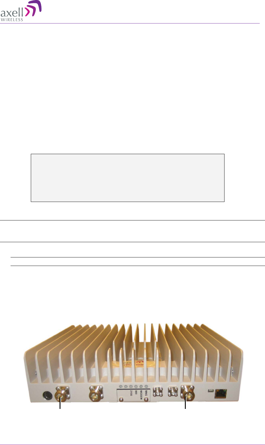
Figure 3-6. Antenna Connections
Mobile
Base
AXELL DIGIMINI- AMERICAS REPEATER
PRODUCT DESCRIPTION AND USER’S MANUAL
18 DIGImini Americas User Manual Rev 3.5 © Axell Wireless Ltd
3.1.7 Power Up
To power up
Connect the Repeater P.S. to the AC power outlet and to the Repeater DC connector.
Figure 3-7. Powering Up
3.1.8 What Next?
• Installations without DIGImini Control Unit (DMCU) – continue to Chapter 5 - Setup and
Configuration
• Installations with DMCU – refer to Chapter 6 - DMCU Installation and Management.
Connect to
Repeater Power
Connect to
110/240 VAC

AXELL DIGIMINI- AMERICAS REPEATER
PRODUCT DESCRIPTION AND USER’S MANUAL
© Axell Wireless Ltd DIGImini Americas User Manual Rev 3.5 19
4 Two Dual Units (Quad-band) Installation
This procedure describes how to assemble and install the DIGImini Quad-band assembly consisting
of two repeaters. If your installation includes a DMCU, only one DMCU is required for the complete
quad-band assembly (two repeaters).
4.1 Overview
NOTE: The Donor and Mobile antennas can be positioned and installed (without being connected
to a Repeater) at any time either before or after mounting and grounding the Repeater.
1. Unpack the Repeater Tri/Quad-band kit.
2. Mount the wallmount bracket on the wall
3. Assemble the RF Combiners and Combiner Spacers onto the Quad-band brackets.
4. Using the supplied brackets, position the repeaters back to back on a flat surface and interconnect
the required interfaces as described in section 4.5.
5. Pick-up the two-Repeater assembly and hang on the mounted wall bracket.
6. Mount the Power Supplies on the wall bracket (do not connect power).
7. Perform the required isolation and link tests.
8. Connect the antennas.
9. Power-on the Repeater.
10. For installations with a DMCU is available, mount the unit (adjacent to the Repeater, on the wall,
and connect to the Repeater according to the instructions in Chapter 6.
AXELL DIGIMINI- AMERICAS REPEATER
PRODUCT DESCRIPTION AND USER’S MANUAL
20 DIGImini Americas User Manual Rev 3.5 © Axell Wireless Ltd
4.2 View of the Quad Band Installation
The following figure illustrates the Triple/Quad-band DIGI-mini assembly.
Note the following:
• The Tri/Quad-band assembly supports the same basic interfaces (ETH, Power, LEDs) as the
Single/Dual-band unit (see 1.6. DIGImini Interfaces) in addition to two RF combiners, mounted
on each side bracket.
• The front panel LED interfaces are interconnected and covered with a common tab.
Note: Illustration below shows a bottom view of the mounted Quad-band assembly (connectors face
down when the assembly is wall mounted).
Figure 4-1: Cascaded DIGImini Tri-band/ Quad-band
DIGImini Unit
Combiner- one
on each side
Power
Supply –
one
on each side
Cascading
Bracket –
on
each side
DIGImini Unit
Common
indicators
Wall bracket
Spacer between
Combiner and bracket
AXELL DIGIMINI- AMERICAS REPEATER
PRODUCT DESCRIPTION AND USER’S MANUAL
© Axell Wireless Ltd DIGImini Americas User Manual Rev 3.5 21
4.3 Required Tools and Materials
The following is required in order to install the Repeater:
• Standard professional tool box
• A computer (i.e. laptop for running the setup)
4.4 DIGImini Tri/Quad-band Kit
The Quad-Band Upgrade Accessory Kit contents are packaged in a single box, consisting of three
layers of items as shown and additional items (screws, ties, etc.) that may be located in any of the
layers.
Figure 4-2. Quad-Band Upgrade Accessory Kit Package
Upon receiving the kit, perform the following:
1. Examine the shipping container for damage before unpacking the unit.
2. Perform a visual inspection to reveal any physical damage to the items.
3. Verify that all of the items are included in the relevant layer as described. Otherwise contact
Axell Wireless.
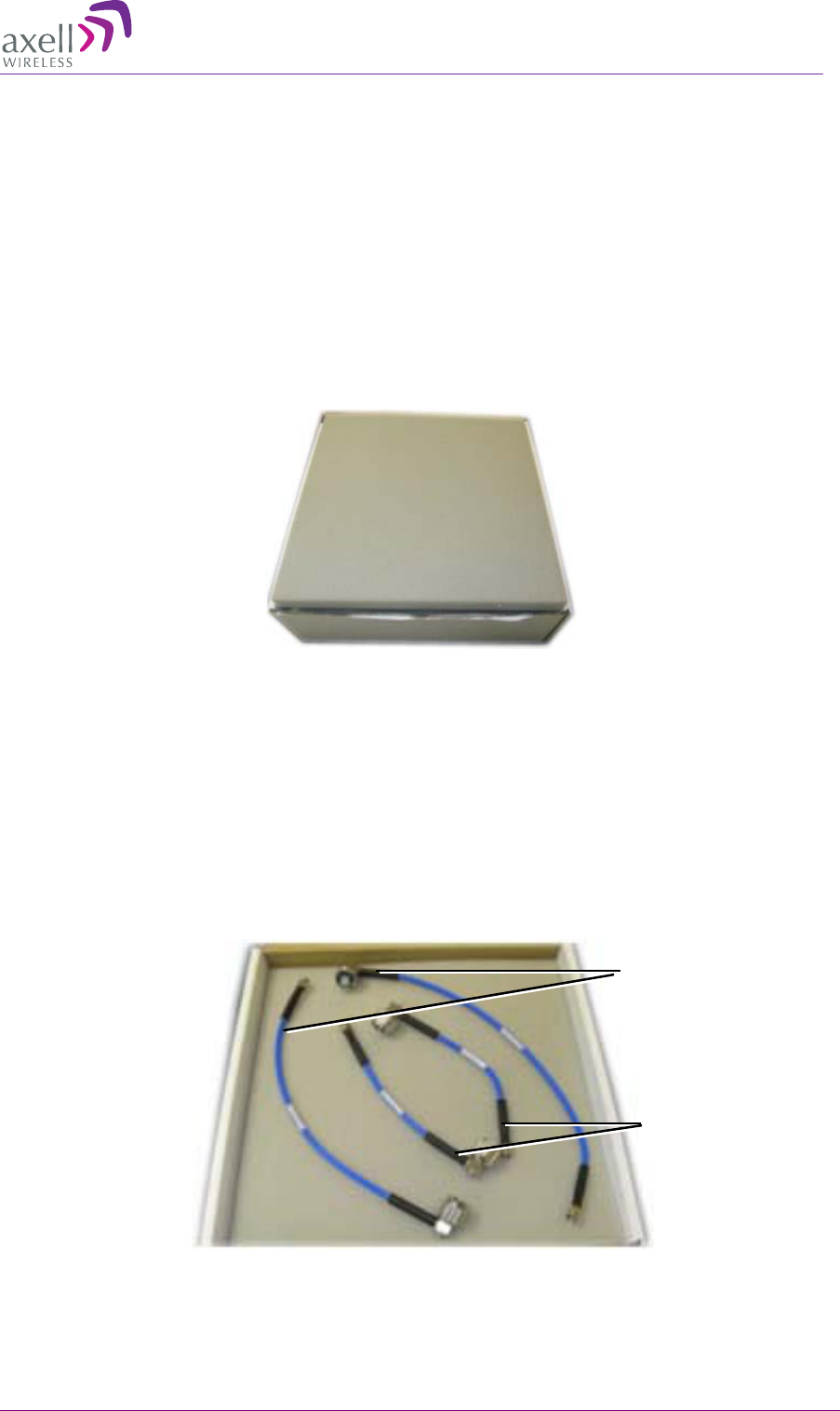
4.4.1 Top Layer Items
Figure 4-3. Quad-Band Upgrade Accessory Kit – Top Layer
X2 Long Coupling SMA
jumper cables
X2 Short Coupling
SMA jumper cables
AXELL DIGIMINI- AMERICAS REPEATER
PRODUCT DESCRIPTION AND USER’S MANUAL
22 DIGImini Americas User Manual Rev 3.5 © Axell Wireless Ltd
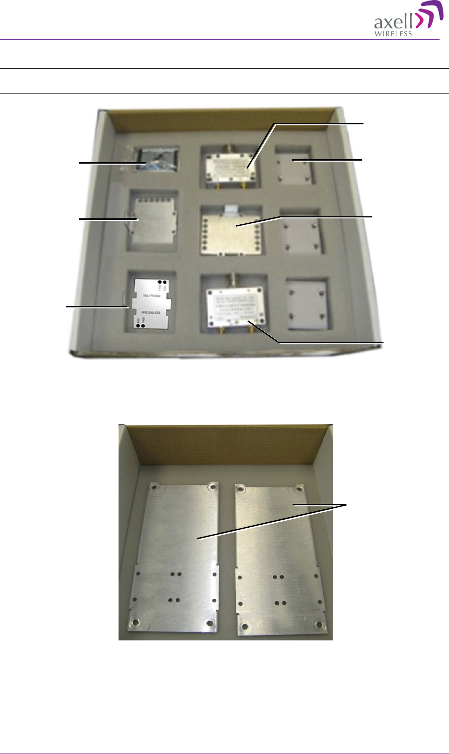
4.4.2 Middle layer Items
NOTE: References to Type I and Type II DIGImini models are explained in the following sections
when the relevant instructions are given.
Figure 4-4. Quad-Band Upgrade Accessory Kit -Middle Layer items
4.4.3 Bottom Layer Items
Figure 4-5. Quad-Band Upgrade Accessory Kit-Bottom Layer Items
Flat Cable +
Combiner
Spacers
X1 Quad-band
plate for Type I
+ Type II units
configuration
Frequency
Labels for
Type-
2
combinations
x3 Quad-band
plate for two
Type I units
RF Combiner
RF Combiner
x1 Quad-band
plate for two
Type II
configurations
2 x Expansion, Side
Brackets
AXELL DIGIMINI- AMERICAS REPEATER
PRODUCT DESCRIPTION AND USER’S MANUAL
© Axell Wireless Ltd DIGImini Americas User Manual Rev 3.5 23
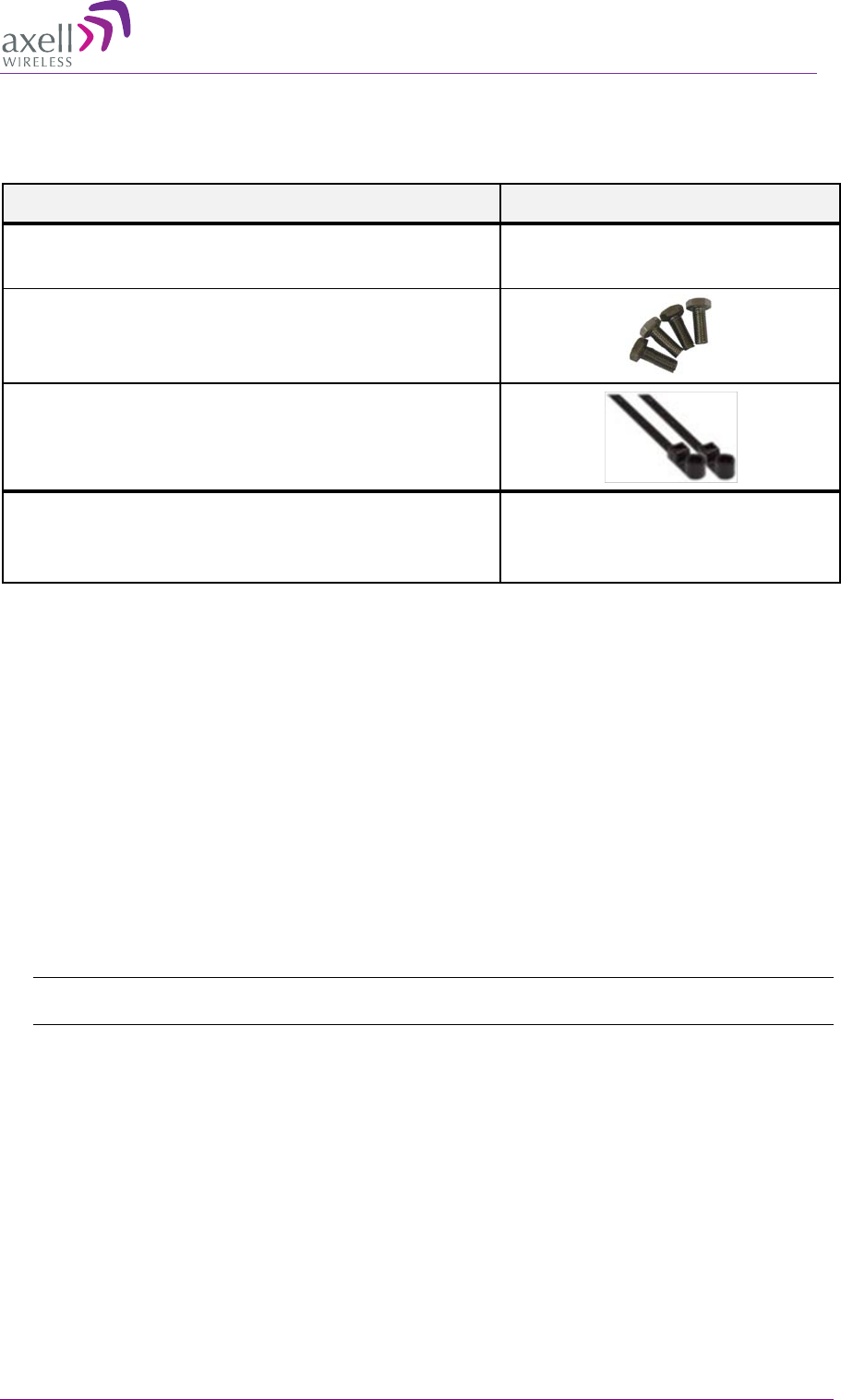
4.4.4 Additional Items
The following additional items are included in the accessory kit and may be packaged in any one of
the layers.
Item Image
8 x Bolts, 8 x Nuts – for Combiner to Spacer to Bracket
assembly
4 x Repeater Mounting Bolts
Ties -
used for securing power supply (only x2 are
required for each power supply –
extra ties may be
included in the kit)
4 x Screws (In use only with the flat cable cover plate of
new chassis (any Type 2 combination)
, to connect the
plate)
4.5 Upgrading to a Quad-Band System
4.5.1 Assemble the DIGImini Units
The upgrading procedure is partially performed on a flat surface.
1. To upgrade an existing DIGImini Dual band installation:
• Remove power from the currently mounted DIGImini.
• Disconnect all antenna, communication and control cables.
• Loosen the side screws and remove the Repeater – leaving the wallmount bracket on the
wall.
• Continue with step-3.
2. For a complete Tri/Quad-band installation (no existing unit):
Note: If holes are to be drilled, use the bracket to mark the hole locations prior to the following
assembly procedure.
• Follow the (wallmount) bracket mounting instructions in 3.1.4 - Mounting Repeater.
• Continue to following Step -3.
AXELL DIGIMINI- AMERICAS REPEATER
PRODUCT DESCRIPTION AND USER’S MANUAL
24 DIGImini Americas User Manual Rev 3.5 © Axell Wireless Ltd
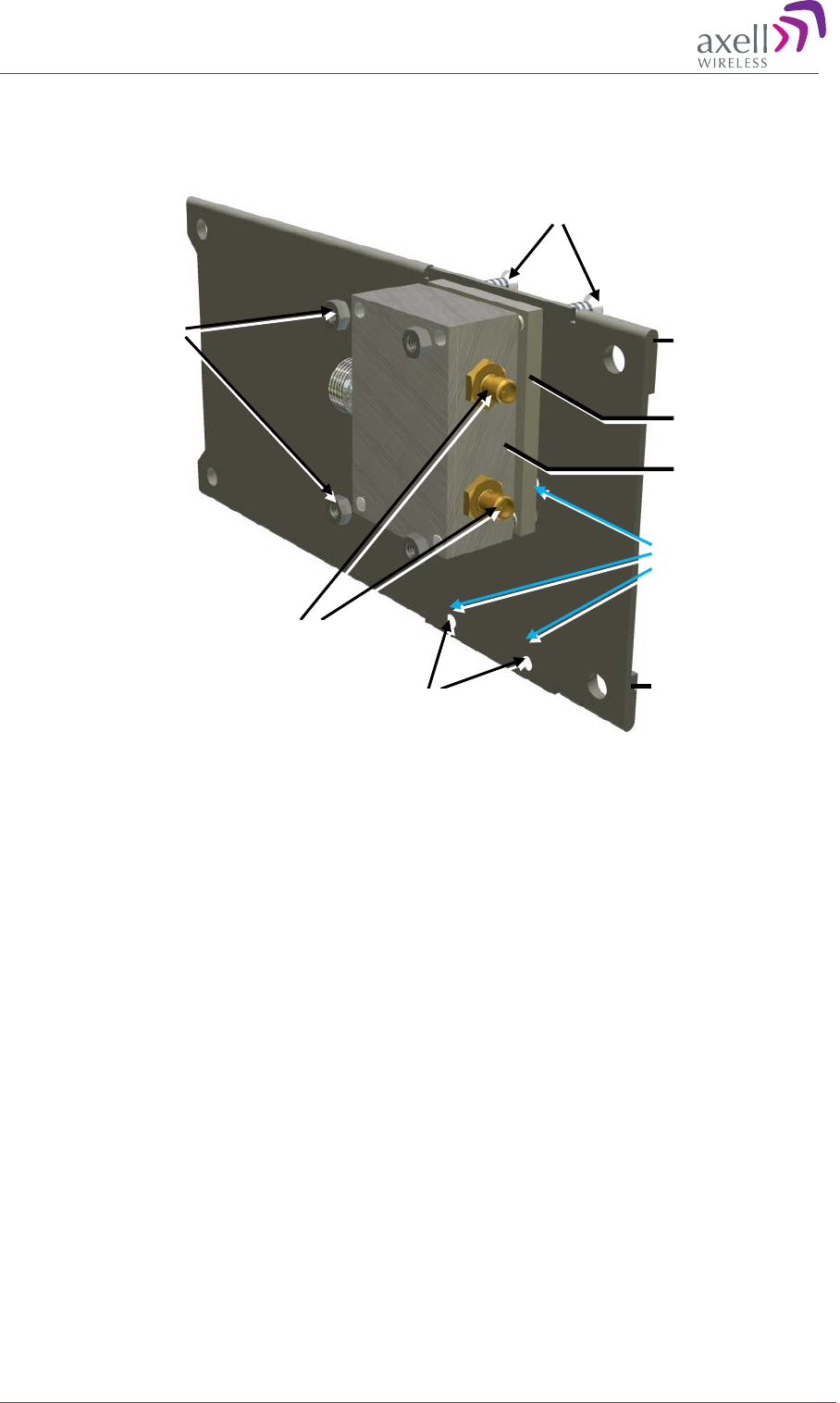
3. If not already assembled:
Assemble each Combiner and Spacer to a Bracket – using the supplied bolts, washers and nuts
for each assembly. Note direction of bracket.
Figure 4-6. Combiner and Spacer Secured to Side Cascading Bracket
X2 connectors
facing this direction
Side Bracket
X2 holes facing
this direction
X4 bolts and
washers
Spacer
X4 Nuts
Combiner
Bracket edge folding over
– AWAY from combiner
Assemble RIGHT
side combiner on
these holes
AXELL DIGIMINI- AMERICAS REPEATER
PRODUCT DESCRIPTION AND USER’S MANUAL
© Axell Wireless Ltd DIGImini Americas User Manual Rev 3.5 25
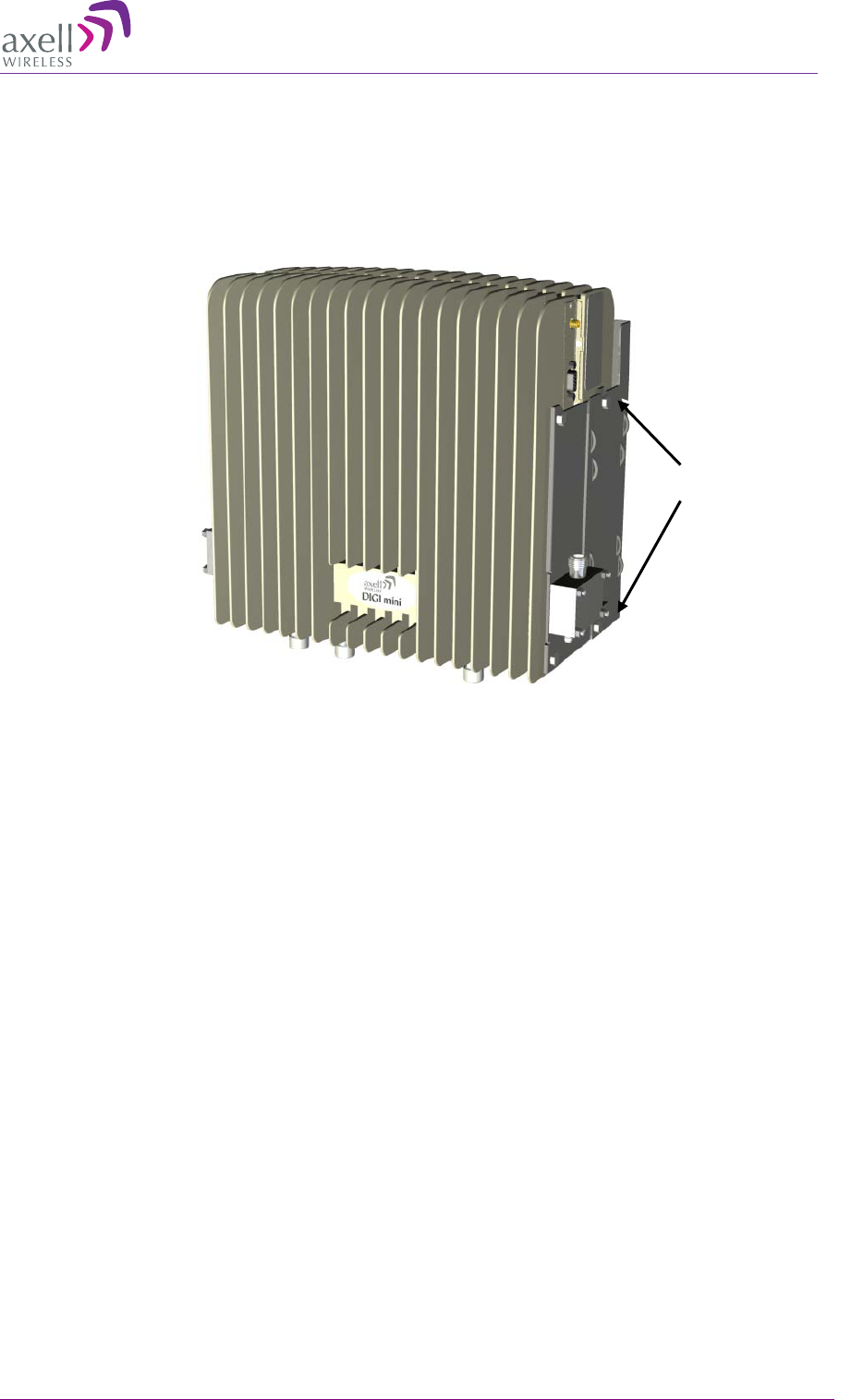
4. Assemble Side Brackets on bottom Repeater:
• Place one of the Repeaters on a flat surface – ridges facing down. This will be the bottom
repeater.
• Noting orientation - loosely assemble the side plate brackets on both sides of the bottom
repeater.
Figure 4-7. Assemble Side Brackets on Bottom Repeater
Secure Loosely on each side
– but enough to hold when
assembly is picked up
Assemble RIGHT side
combiner on these holes and
bottom holes
AXELL DIGIMINI- AMERICAS REPEATER
PRODUCT DESCRIPTION AND USER’S MANUAL
26 DIGImini Americas User Manual Rev 3.5 © Axell Wireless Ltd
5. Assemble top Repeater:
• Place second repeater back-to-back (flat surfaces together) on bottom repeater.
• Align the top repeater holes with the top side bracket holes and tightly secure. (You may
need to place your hand between the two repeaters in order to maintain the appropriate
separation between the repeaters, allowing the alignment of the bracket holes to the
repeaters.)
Figure 4-8. Assemble Top Repeater
6. Remove the LED plates of BOTH Repeaters and set them aside.
Figure 4-9. Removing Dedicated Tabs
Loosely
secured
Unscrew and
remove plates
Unscrew and
remove plates
Repeater
Repeater
Space
Tightly secure
(do the same for other
bracket on other side)
AXELL DIGIMINI- AMERICAS REPEATER
PRODUCT DESCRIPTION AND USER’S MANUAL
© Axell Wireless Ltd DIGImini Americas User Manual Rev 3.5 27
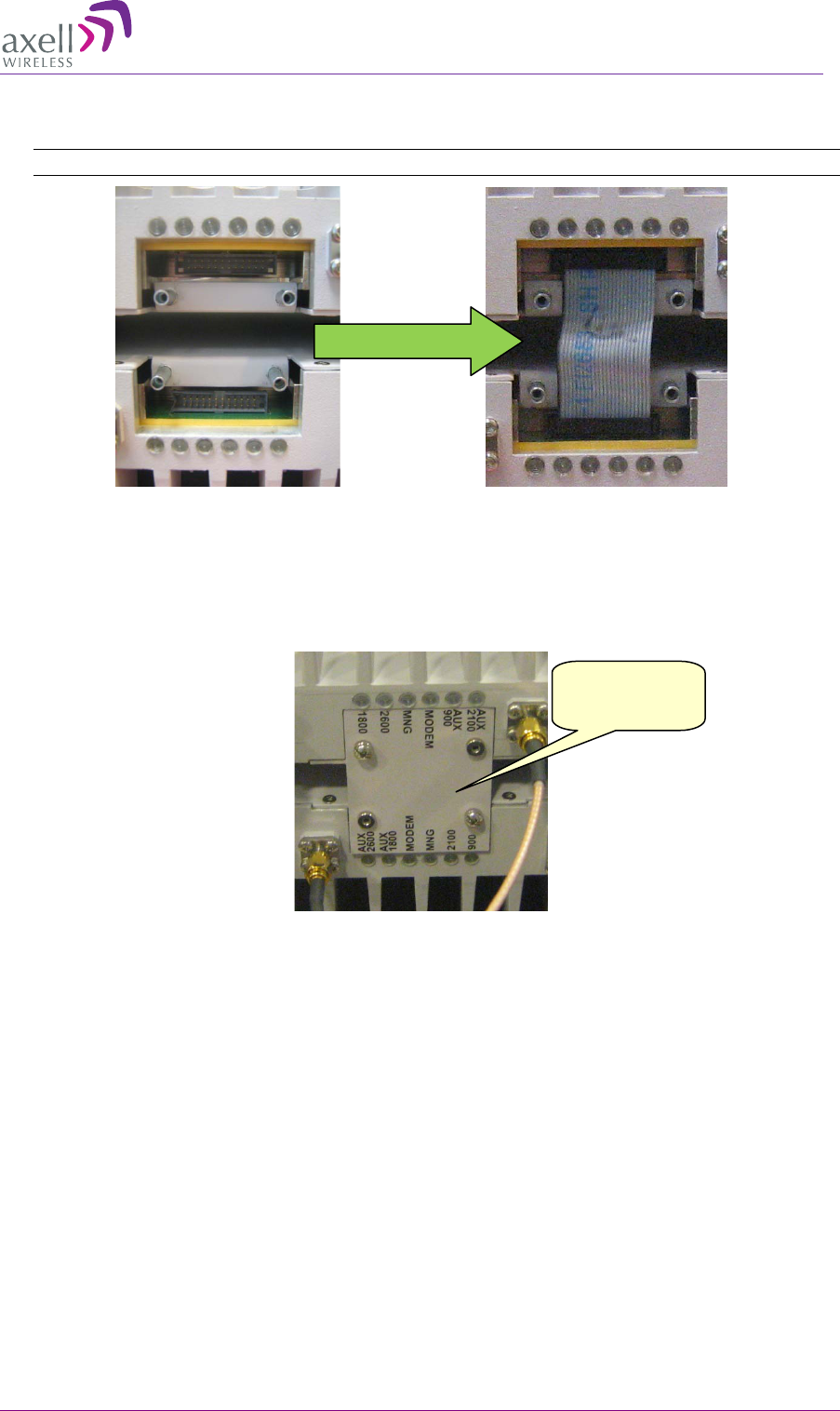
7. Carefully, connect the supplied flat cable between the two connectors as shown below. Verify
that the flat-cable is securely connected.
NOTE: Handle Flat Cable with care when connecting.
Figure 4-10. Interconnecting Flat cable
8. Cover the flat-cable with the provided Flat Cable Cover Plate and secure using the four screws.
Choose the appropriate cover plate (and also label for some plates) according to the criteria
described in following section.
Figure 4-11. Assembling Interconnecting Cover Plate
Plate covering
flat cable
AXELL DIGIMINI- AMERICAS REPEATER
PRODUCT DESCRIPTION AND USER’S MANUAL
28 DIGImini Americas User Manual Rev 3.5 © Axell Wireless Ltd
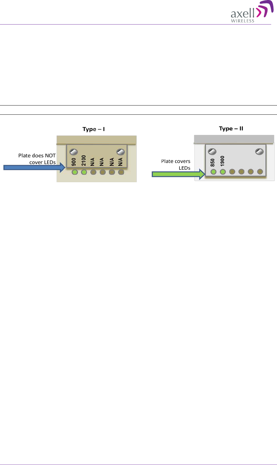
4.5.2 Assembling Quad-Band Plates and Labels
The LED plates and markings on the DIGImini units to be combined will be one or a combination of
Type I, or/and Type II as shown below.
There are two differences:
• Label markings – without N/A (Type I) or with N/A (Type-II)
• LEDs are covered (Type II) or not covered (type I) by tab
NOTE: The frequencies are examples.
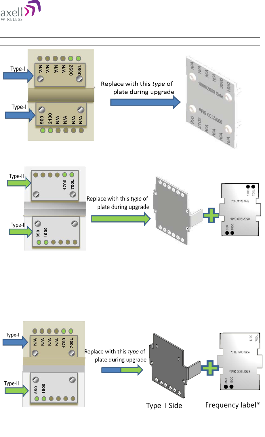
Three different Quad-Band plate types are provided for the following quad-band combinations:
• Both units in quad-band are Type I
• Both units in quad-band are Type II
• One of each Type (Type I + Type II)
AXELL DIGIMINI- AMERICAS REPEATER
PRODUCT DESCRIPTION AND USER’S MANUAL
© Axell Wireless Ltd DIGImini Americas User Manual Rev 3.5 29
4.5.2.1 Both DIGImini Units are Type I
IMPORTANT!!! Be sure to choose the proper frequency label for each unit- note direction.
4.5.2.2 Both DIGImini Units are Type II
Use the following tab and label type (label according to frequency).
*Choose appropriate label according to the original frequencies of each unit and stick on tab
4.5.2.3 Combination of Type I and Type II DIGImini Units
Use the following tab and label type (label according to frequency).
*Choose appropriate label according to the original frequencies of each unit and stick on tab
Existing Plates on both DIGImini
Type II Units
New Quad-Band Plate and Label for
DIGImini Type II Units
Frequency Label*
Type I Side
AXELL DIGIMINI- AMERICAS REPEATER
PRODUCT DESCRIPTION AND USER’S MANUAL
30 DIGImini Americas User Manual Rev 3.5 © Axell Wireless Ltd
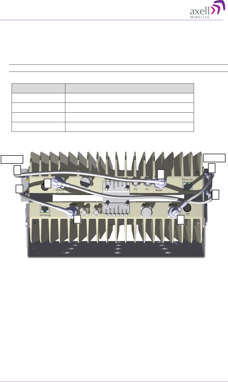
4.5.3 Connect SMA Jumper Cables
Connect SMA N-type jumper cables between Combiners and Repeater antenna ports according
to the illustration below:
NOTE: Be sure to use recommended Torque value.
Jumper Type Connect Between
Short (170mm) Connect between connectors labeled 1 (i.e 1 to 1)
Short (170mm) Connect between connectors labeled 4 (i.e 4 to 4)
Long (340mm) Connect between connectors labeled 2 (i.e 2 to 2)
Long (290mm) Connect between connectors labeled 3 (i.e 3 to 3)
Figure 4-12. DIGImini Tri/Quad-Band Jumper Connections
BASE Mobile
3
3
2
2
4
4
1
1
AXELL DIGIMINI- AMERICAS REPEATER
PRODUCT DESCRIPTION AND USER’S MANUAL
© Axell Wireless Ltd DIGImini Americas User Manual Rev 3.5 31
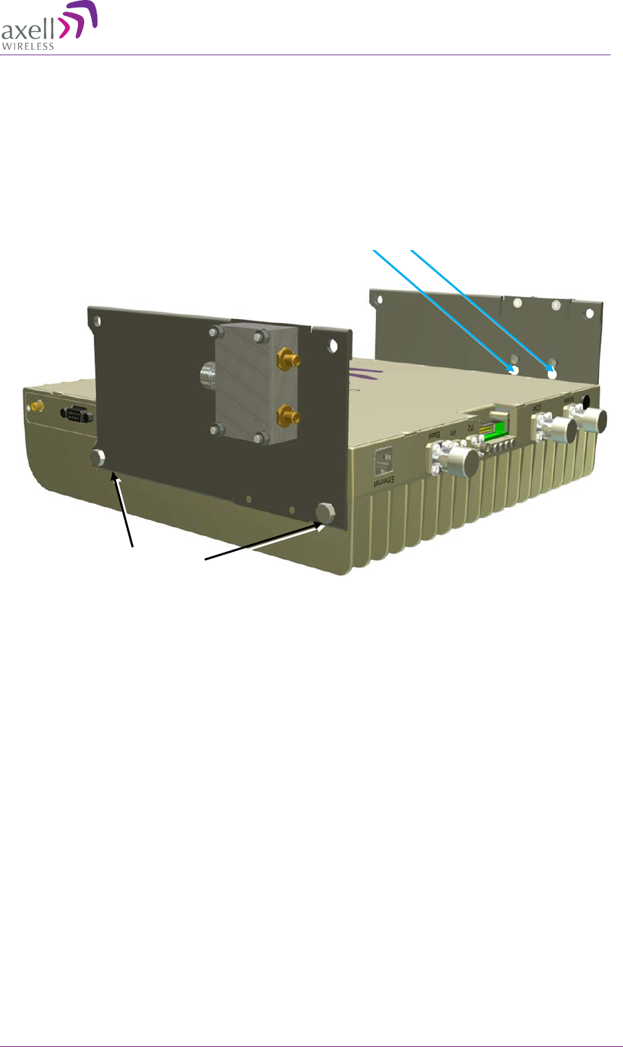
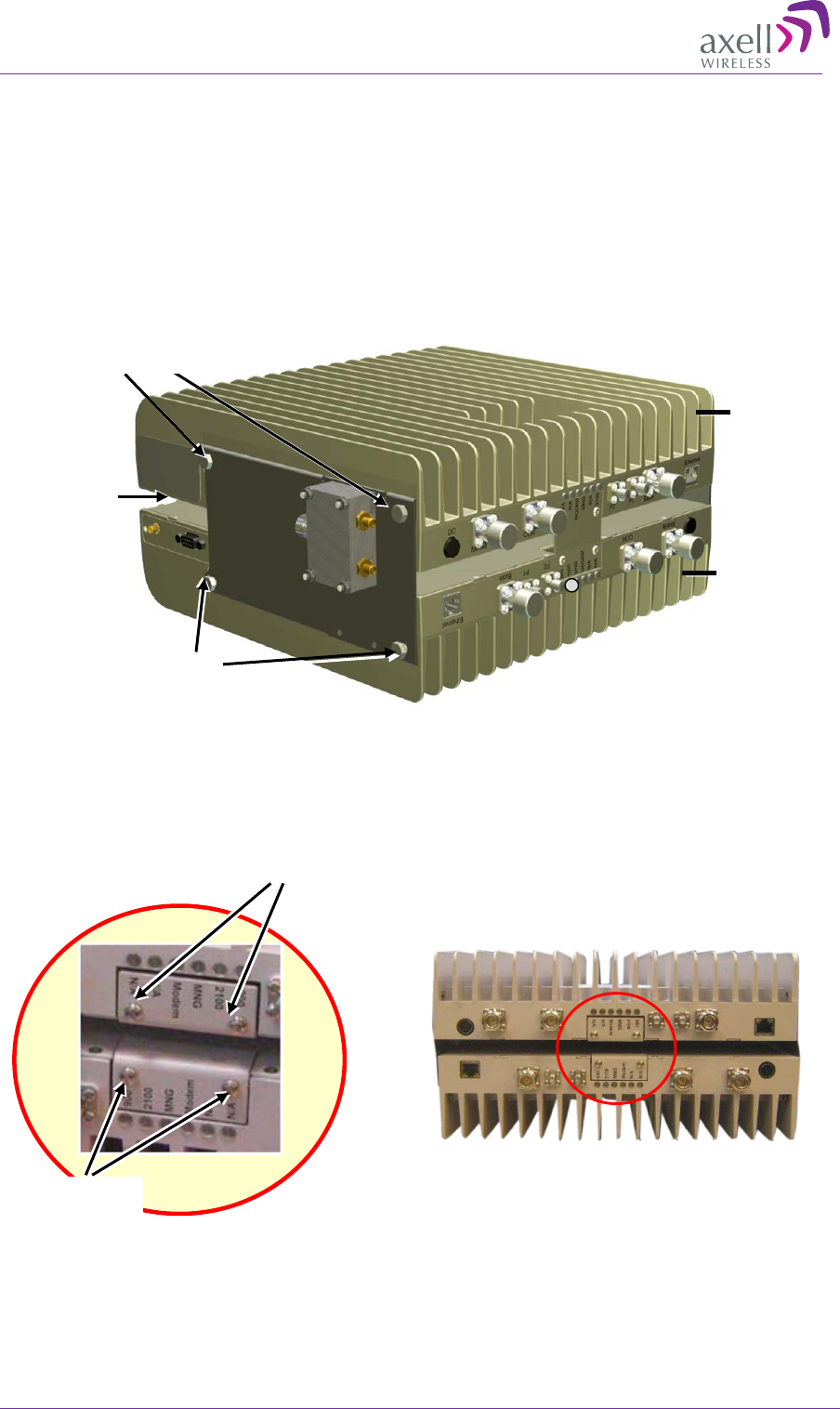
9. Referring to the following figure:
• Carefully and securely pick up the assembly.
• Hang the assembly on the wall bracket, fitting the looser bottom Repeater Side Bracket
screws on the wall bracket.
• Tighten the loose screws on each side.
Figure 4-13. Mount Quadband Assembly on Wallbracket
Tighten on
each side
AXELL DIGIMINI- AMERICAS REPEATER
PRODUCT DESCRIPTION AND USER’S MANUAL
32 DIGImini Americas User Manual Rev 3.5 © Axell Wireless Ltd
10. Two Power Supplies should be assembled on the wallbracket (one on each side of the
assembly). Mount one (if this is an upgrade and one is already mounted) or both (if this is a new
installation) as follows:
• Thread two ties through the loops in the bracket.
Figure 4-14. Insert Ties for Securing Power Supply
• Fit Power Supplies on ridge(s) on side of wall bracket.
• Secure the ties.
,
Figure 4-15. Secure Power Supply
Thread x2 ties through
loops (1x on bottom
and 1x on top)
Ties
AC/DC
Converter PS
AXELL DIGIMINI- AMERICAS REPEATER
PRODUCT DESCRIPTION AND USER’S MANUAL
© Axell Wireless Ltd DIGImini Americas User Manual Rev 3.5 33
4.5.4 Before Connecting the Antennas or Power
Before connecting the antennas or power perform the procedures described in section .
4.5.5 Antenna Connections
CAUTION! DO NOT CONNECT THE ANTENNA CABLES TO THE REPEATER
BEFORE VERIFYING THE INSTALLATION PARAMETERS.
CAUTION! DO NOT POWER-UP THE REPEATER WITHOUT EITHER THE
ANTENNAS BEING CONNECTED OR THE ANTENNA CONNECTIONS TERMINATED
WITH DUMMY LOADS.
To connect the antennas to the Repeater
NOTE: If the coaxial cables are NOT weather-resistant type, wrap the exterior coaxial cables with
insulation and holding tape (Type 3M Rubber splicing tape) for environmental protection and to
ensure longer lifetime.
1. Install the antenna cables along their path to the Repeater, and connect them to the Antennas.
NOTE: Be sure to use low loss cables.
2. Connect the Donor (Base) antenna to the rear port of the LEFT Combiner (connected to the
Repeater BASE ports). (Donor antenna specifications and installation criteria are described in
section 2.1).
3. Connect the Service antenna to the rear port of the RIGHT Combiner (connected to the
Repeater MOBILE ports.) (Mobile antenna specifications and installation criteria are described in
section 2.2).
4. Verify all RF connectors are tightened and the cables and antennas are secured.
Figure 4-16. Service and Donor Antenna Connections
Donor Antenna
Service Antenna
AXELL DIGIMINI- AMERICAS REPEATER
PRODUCT DESCRIPTION AND USER’S MANUAL
34 DIGImini Americas User Manual Rev 3.5 © Axell Wireless Ltd
4.5.6 Power Up
To power up
1. Connect each Power Supply (AC/DC Converter) output to a Repeater front panel DC power
connector.
2. Connect each of the Repeater P.S. units’ to the AC power outlet.
Figure 4-17. Powering Up (shown with illustration of Combiner)
4.5.7 What Next?
• Installations without DIGImini Control Unit (DMCU) – continue to 5 - Setup and Configuration.
• Installations with DMCU – refer to Chapter 6 - DMCU Installation and Management.
Connect this side
to 110/240 VAC
Donor Antenna
Connect this side to
Repeater
front panel
DC connector
AXELL DIGIMINI- AMERICAS REPEATER
PRODUCT DESCRIPTION AND USER’S MANUAL
© Axell Wireless Ltd DIGImini Americas User Manual Rev 3.5 35
5 Setup and Configuration
NOTE: This section is relevant to installations that do not include DMCU. For installations with
DMCU unit, continue to Chapter
6.
The Mini-Repeater is designed for simple plug-and-play operation, only requiring the setup of a
number of parameters (such as DL Output Power, bandwidth, and gain) through a local Web
connection and verifying that the system is operating properly.
The setup procedure consists of the following steps:
1. Open a local Web session to the Repeater.
If you are not familiar with the Axell Web Access application, it is recommended to quickly
review the Navigating the Web GUI Application section.
2. Adjust the signal levels and configuring the sub-bands and verify that no Alarms are generated.
5.1 Open a Direct Local WEB Session to the
Repeater
These instructions are valid only for installations without a DMCU.
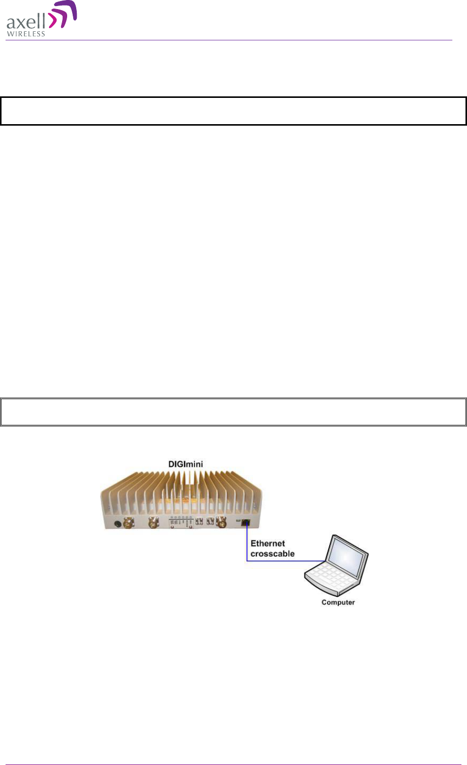
To connect directly to the Repeater
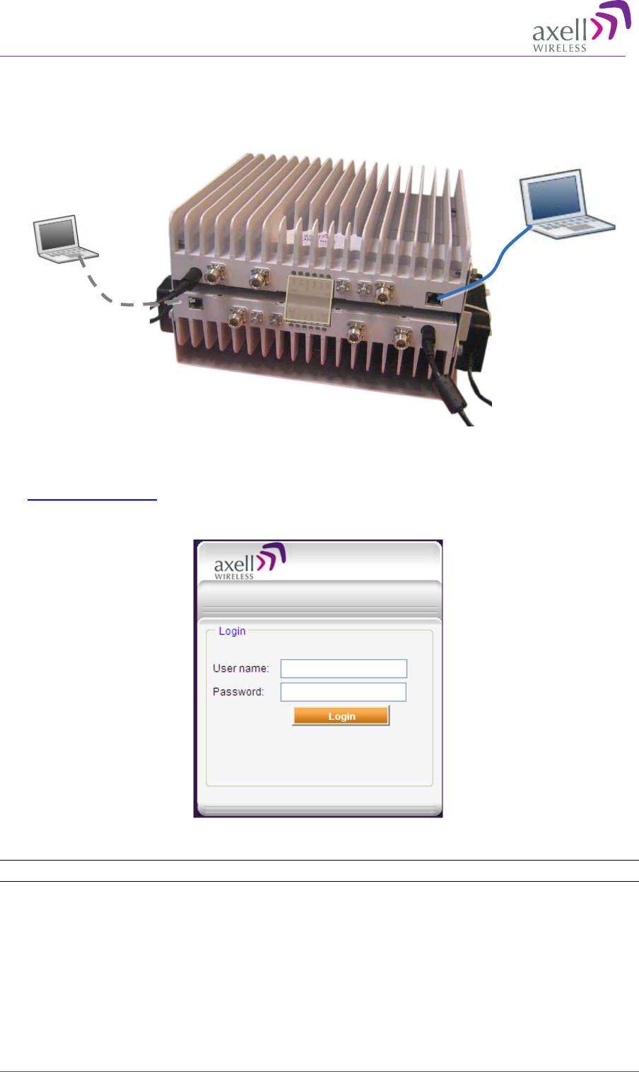
1. Connect the supplied Ethernet cross-cable from the computer to the Repeaters’ front panel.
ATTENTION! Do not connect the Repeater ETH port to the network. It may affect your network!
Remote management is available only via a DMCU.
Figure 5-1. Ethernet Connection to a Single DIGImini Repeater
AXELL DIGIMINI- AMERICAS REPEATER
PRODUCT DESCRIPTION AND USER’S MANUAL
36 DIGImini Americas User Manual Rev 3.5 © Axell Wireless Ltd
2. If connecting to the Tri/Quad-band assembly, connect the cable to any of the two repeaters. The
Web GUI will allow for configuration of both repeaters.
Figure 5-2: Cascaded DIGImini Tri-band and Quad-band
3. In the address line, type digimini or enter the default IP address of the Repeater.
http://192.168.1.253. A session will be established with the Repeater and the login dialog
appears.
4. Type the default User Name admin and the default Password admin.
NOTE: Bothe entries are case sensitive and must be entered with lower case letters.
5. Click Login. The application main window appears.
6. Quickly review the following section describing the application window and then proceed to
configure the signal levels according to section 5.2.3.
Ethernet cross-
cable
Connect to either unit
AXELL DIGIMINI- AMERICAS REPEATER
PRODUCT DESCRIPTION AND USER’S MANUAL
© Axell Wireless Ltd DIGImini Americas User Manual Rev 3.5 37
5.2 Navigating the Web GUI Application
This section describes how to navigate the Web Management application. The Web Access interface
provides Repeater RF parameters control and monitoring options. The displayed bands depend on the
supported configuration: Single, Dual, Triple or Quad band configuration.
NOTE: The CMU (Control Monitoring Unit) item in the topology tree is only accessible for sessions
opened via the Digital Monitoring Control Unit (DMCU) - see section
6.5.2 for details. For sessions
opened by direct connection to a DIGImini front panel, the CMU item will appear but will not be
accessible.
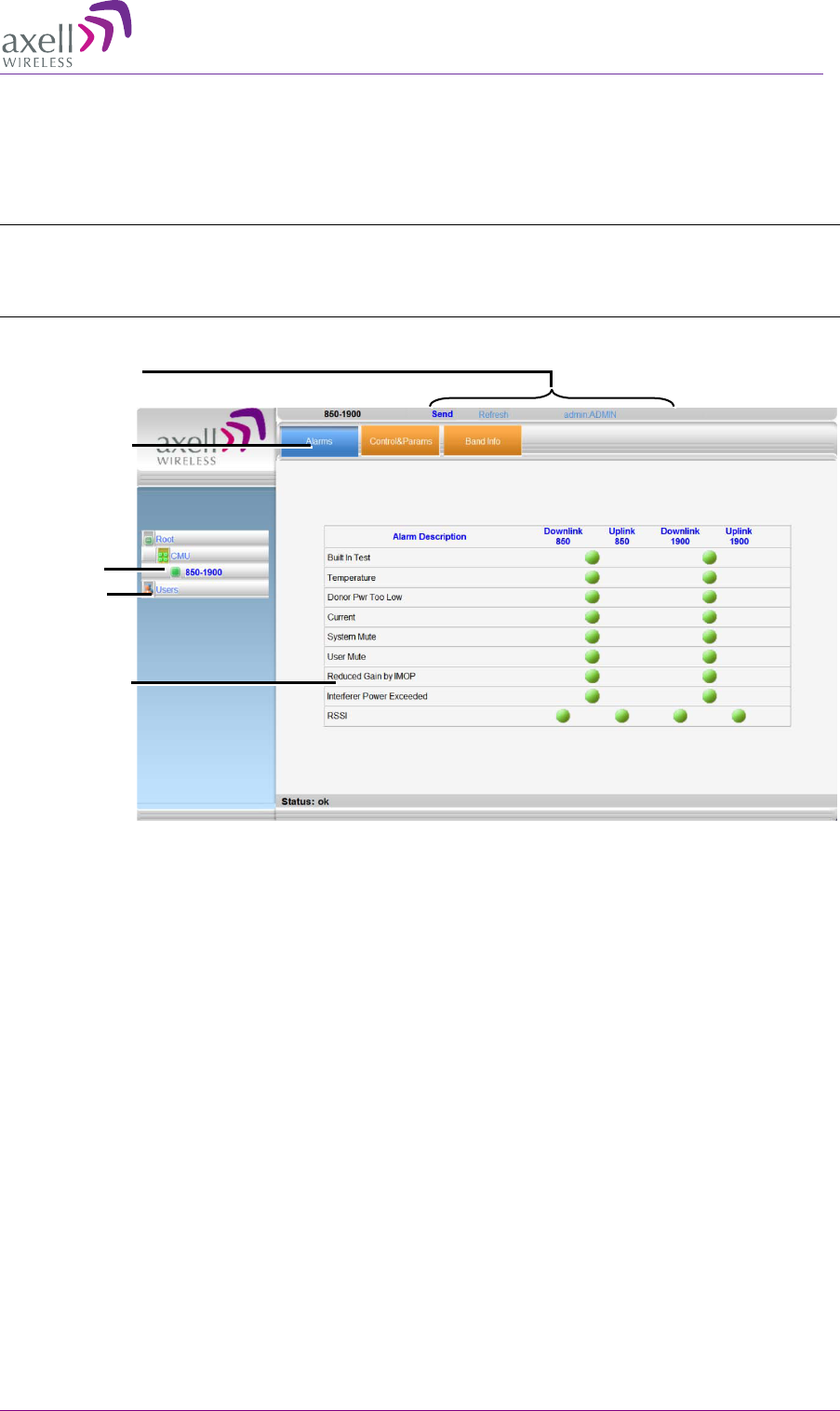
Figure 5-3. Example of Web GUI Screen (shows dual-band)
Band Item
Pane related to
selected tree
item
Operation
Buttons
Tabs related to
Band item
User
Management
AXELL DIGIMINI- AMERICAS REPEATER
PRODUCT DESCRIPTION AND USER’S MANUAL
38 DIGImini Americas User Manual Rev 3.5 © Axell Wireless Ltd
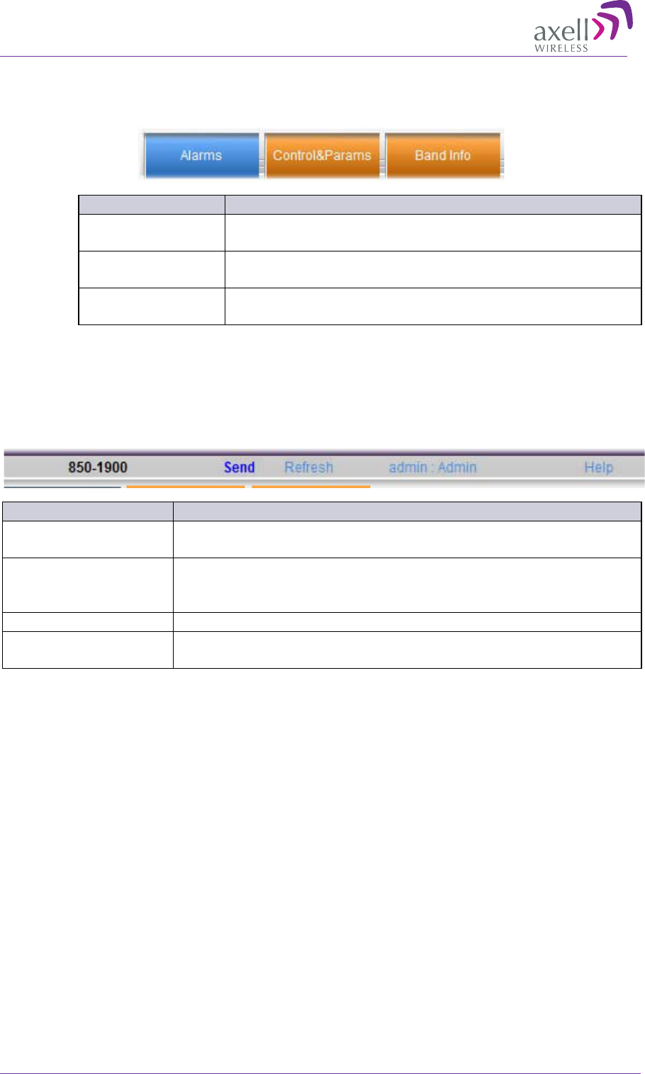
5.2.1 Band Pane and Tabs
The upper area of each selected pane shows the tabs corresponding to that pane.
Item
Description / Values
Alarms
Displays various alarms generated by the Repeater and enables
monitoring
Control and Params
Used for adjusting RF parameters and channel configuration
(signal level, gain and bandwidth)
Band Info
Shows information on the selected band, including valid
definable bandwidth pre sub-band.
5.2.2 Operation Buttons
The following Operation buttons are available.
Item
Description / Values
Selected Tree Item
Shows the currently selected topology tree item.
Values: Band (e.g. 850-1900), Users
Send
Click after completing the new data input and values update in any
screen in order to insert the new values into the Repeater, and
implement the changes
Refresh
Click to refresh the current screen and update the displayed data
Help
Click Help to display an e-guide line for the system operation. This
Help is general by its nature and some features may not be included.

AXELL DIGIMINI- AMERICAS REPEATER
PRODUCT DESCRIPTION AND USER’S MANUAL
© Axell Wireless Ltd DIGImini Americas User Manual Rev 3.5 39
5.2.3 Signal Levels and Channel Configuration
This section provides a description of the RF Gain setting criteria (set via the Controls and Params
Pane), the criteria determining the number of available bands and a step-by-step procedure of the
signal level and channel configuration procedure.
5.2.4 RF Gain Setting Criteria
The RF Gain is set automatically by the Repeater’s SALC function. The function sets the optimum
gain without exceeding the isolation limit.
The gain range is up to 73dB for all bands and is set by default to its maximum value.
The gain will then be modified automatically to its optimum value by the SALC mechanism. This
mechanism performs gradual learning of traffic load characteristics and adjusts the Repeater RF Gain
accordingly. (See section 1.3 for more information on the SALC mechanism).
5.2.5 Bandwidth and the Number of Available Bands
Each repeater supports either one or two bands (single-band or dual-band). Up to Six sub-bands may
be defined per two bands per repeater (e.g. on a dual-band repeater supporting bands 850MHz and
1900MHz, 4 sub-bands may be set for the 850MHz band and 2 sub-bands for the 1900MHz band,
with a total sum of 6 sub-bands). The number of available sub-bands or channels depends on the
technology and selected bandwidth as detailed below (note that some bandwidths (e.g. 15 or 20MHz
at 700/1900 MHz GSM) take up two channel resources).
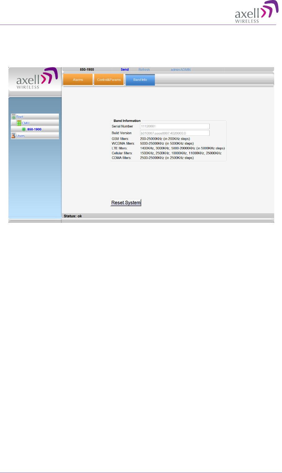
The information can be viewed via the Band Info tab (described on the following page).
Frequency Band (Technology) Technology Filter BW Number of Sub-
band Resources
850/1700/1900MHz CDMA 2.5MHz – 10MHz
(in 2.5MHz steps)
1
850/1700/1900MHz CDMA 12.5MHz – 25MHz
( 2.5MHz steps)
2
850MHz CDMA 1.5, 2.5MHz 1
850MHz CDMA 11MHz 2
700/850/1700/1900MHz LTE 1.4, 3, 5, 10MHz 1
700/850/1700/1900MHz LTE 15,20 MHz 2
850/1700/1900 GSM 200KHz-
11,000KHz
( in 200KHz steps)
1
850/1700/1900 GSM 11200KHz-25MHz
( in 200KHz steps)
2
700/850/1700/1900MHz WCDMA 5, 10 MHz 1
700/850/1700/1900MHz WCDMA 15,20, 25 MHz 2
AXELL DIGIMINI- AMERICAS REPEATER
PRODUCT DESCRIPTION AND USER’S MANUAL
40 DIGImini Americas User Manual Rev 3.5 © Axell Wireless Ltd
To access the Band Information window
1. From the Tree Pane, select the band (e.g. 850-1900).
2. Select the Band Info tab. The relevant parameters are displayed.
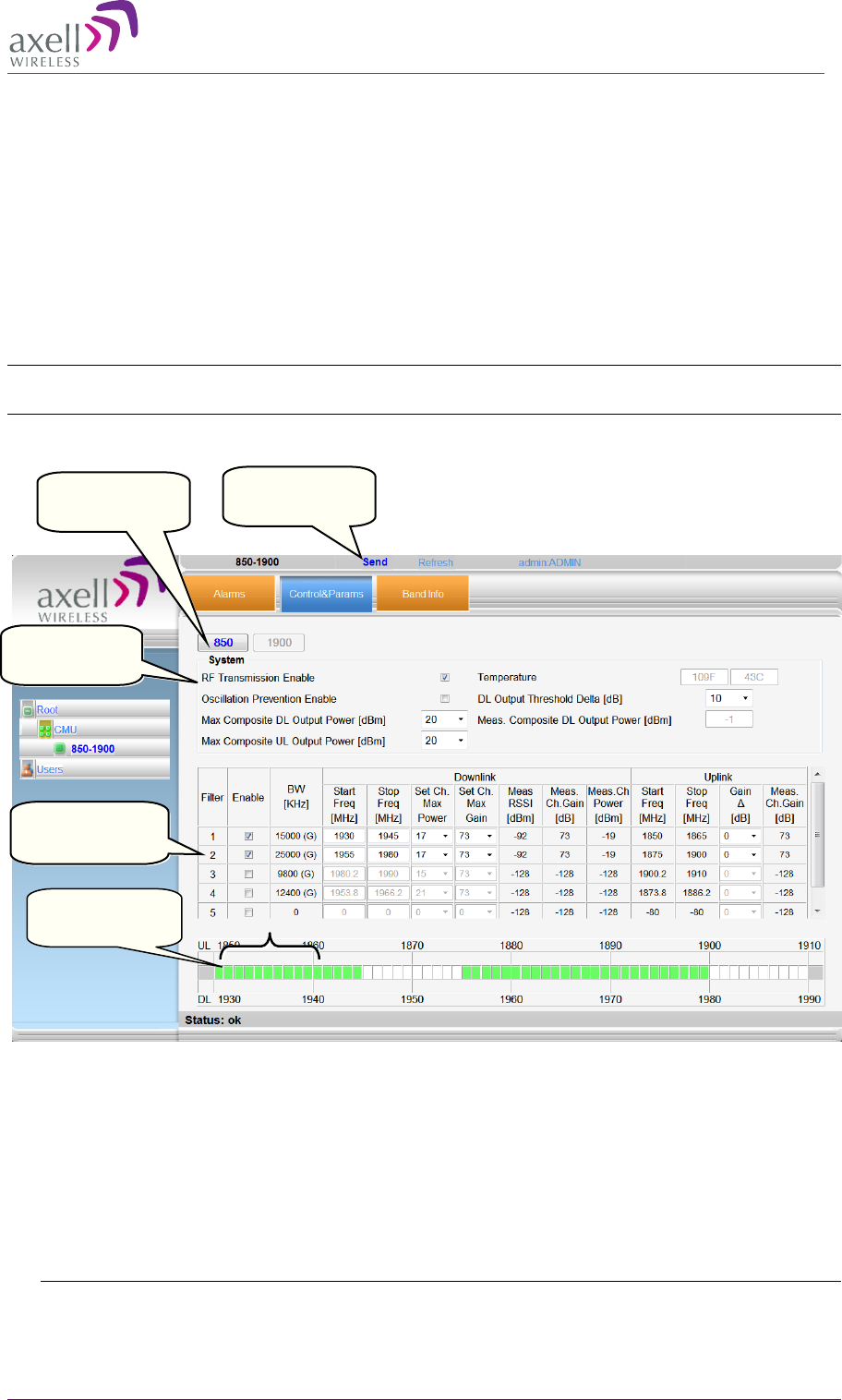
5.2.6 Adjusting the Signal Levels and Configuring Channels
The Control and Params (parameters) window is used to configure the sub-bands and Max UL/DL
Power for the selected band. A dedicated filter configuration dialog is provided for each of the
supported bands (i.e. 700/1700/850/1900) in the Control and Params tab. The dialogs and
configuration procedures are identical for each band, except for the parameter values.
Up to six sub-bands referred to as filters can be defined per two bands, where each sub-band is
individually defined by setting the following:
• Bandwidth - start and stop frequency
• Maximum power
• Maximum gain
• Gain delta
The defined sub-bands are displayed in the lower part of the screen for reference.
AXELL DIGIMINI- AMERICAS REPEATER
PRODUCT DESCRIPTION AND USER’S MANUAL
© Axell Wireless Ltd DIGImini Americas User Manual Rev 3.5 41
To adjust the signal levels and configure the channels
1. In the left pane (Topology Tree), select the supported band configuration (e.g. 850-1900) which
includes the Band item whose sub-bands are to be configured.
2. Click the Control and Params tab. For dual/triple/quad band configurations, click the required
band for configuration and the corresponding pane appears.
The window is divided into the following areas:
• System – overall parameters for the selected service.
• Filter definitions – used to define up to six sub-bands and their RF parameters.
• Sub-bands view – graphical display of defined sub-bands for the service.
Note: You may define up to Six sub-bands per 2 bands, e.g. 4 sub-bands for the 850MHz band and 2
sub-bands for the 1900MHz band (see section
5.2.5 for details).
Figure 5-4. Params and Control Tab (example shows quad-band)
3. Set the System Level parameters:
• Verify that the RF Transmission Enable parameter is checked.
• Set the Max Composite DL Output Power according to your site requirements and click
Send. The Measured Composite DL Output Power is displayed in the adjacent field.
If the composite output power exceeds the defined value, the Smart ALC feature begins working.
• Set the Max Composite UL Output Power according to your site requirements.
Additional parameters (not required for initial setup) are:
Service level
parameters
Click Send with
each change
Sub-band
definition options
Defined
band channels
Select the band
to configure

AXELL DIGIMINI- AMERICAS REPEATER
PRODUCT DESCRIPTION AND USER’S MANUAL
42 DIGImini Americas User Manual Rev 3.5 © Axell Wireless Ltd
• Oscillation Prevention Enable - Enables oscillation detection mechanism that maintains
repeater functionality.
• Temperature - Displays Repeater ambient temperature.
• DL Output Threshold Delta (dB) - the delta from the set Composite Output Power, below
which the alarm 'Donor power is too low' is activated.
For example, if the DL Output Threshold value is set to 8dB, when the Measured Composite
DL output power is 8dB less than the set Composite Output Power, an alarm is generated.
• Meas. Composite DL Output Power – displays the currently measured output signal level.
4. To configure each sub-band:
• Checkmark Enable. The configuration parameters in that row will be available.
• In the Downlink area, set the Start and Stop DL Frequency (MHz). (The Uplink Start and
Stop frequencies will be automatically allocated.)
The defined BW will be displayed in the BW KHz column (to the left of the Start Frequency).
• Set the (Downlink) Max Gain as follows: by default, the MAX Gain (DL) parameter is set to
its highest level (73dB). Change the Channel Max Gain (DL) according to the
measured/calculated input power and isolation measurements.
• The recommended Maximum Gain setting is approximately 15 dB less than the isolation
between the service and donor antennas.
5. If the site NOISE LEVEL is high enough to cause interference, adjust the noise level as follows:
• Adjust the Gain Delta parameter – this sets the delta between the uplink and downlink gain
(so the uplink gain is relatively lower than the downlink gain.
• Click Send.
• Repeat the procedure until the desired coverage is achieved.
6. More information on parameters for the selected sub-band:
• DL Set Ch. Max. Gain Sets the power for the antennas. The value is about 15 dB less than
the isolation between the donor antenna and the mobile antenna.
The Value defined in the DL path is reflected in the UL path, however to define
different UL and DL path values the Gain Delta parameter is used and its defined value
is added to the UL value.
• DL Measured RSSI - measured DL signal.
• DL Measured Ch. Gain - measured DL Gain (dB) for the selected sub-band.
• DL Measured Ch. Power - measured Power (dBm) for the selected sub-band.
• UL Gain Δ - used for noise control. Sets the difference between UL and DL gain.
• UL Measured Ch. Gain - measured UL Gain (dB) for the selected sub-band.
7. Click Send (top window area option).
AXELL DIGIMINI- AMERICAS REPEATER
PRODUCT DESCRIPTION AND USER’S MANUAL
© Axell Wireless Ltd DIGImini Americas User Manual Rev 3.5 43
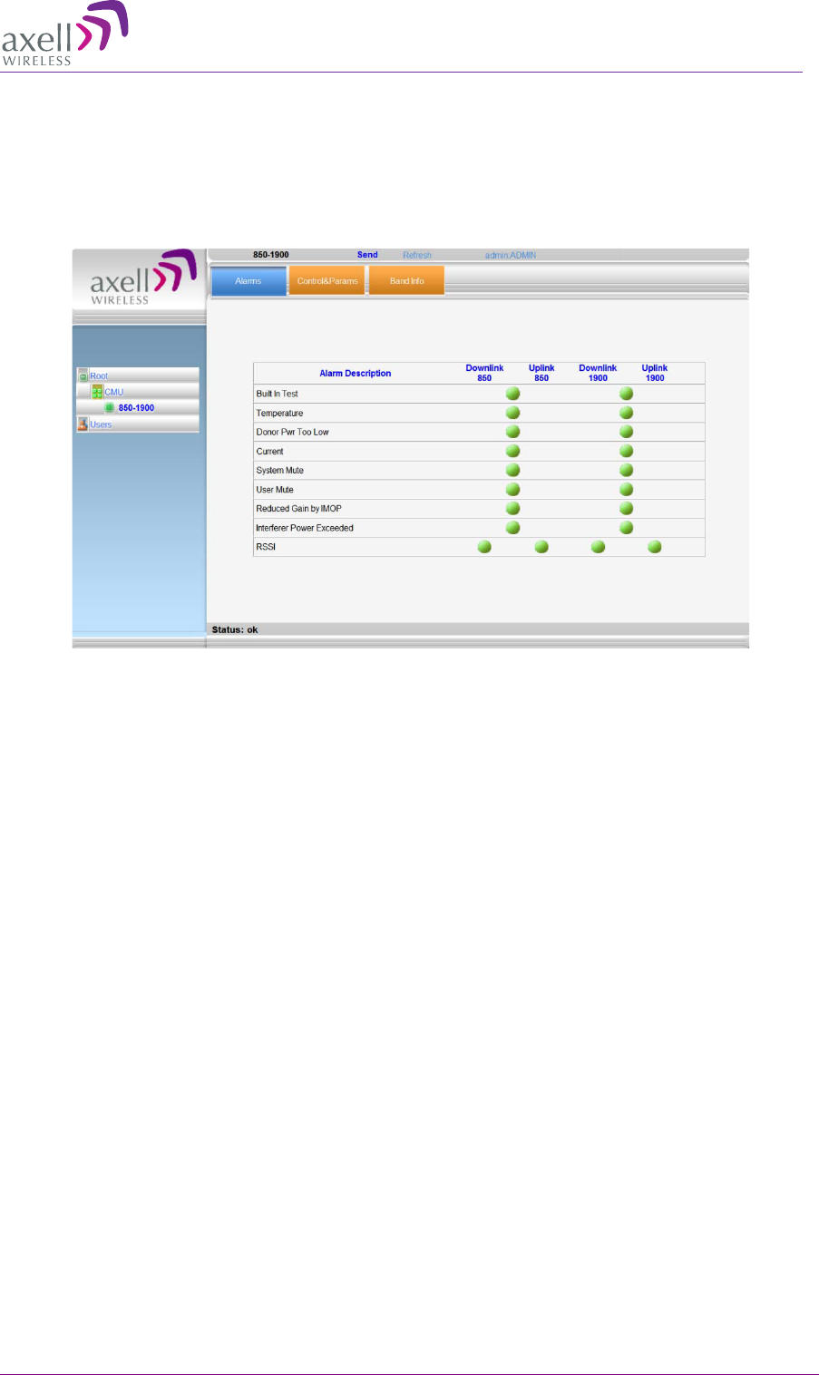
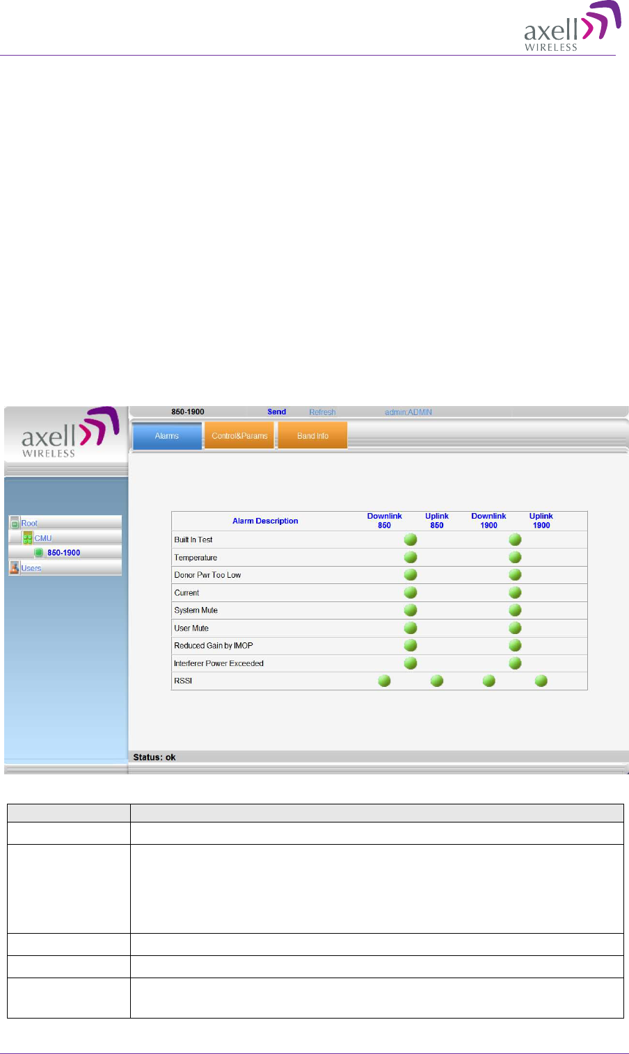
8. After the channels have been configured and the required coverage is attained for the location,
verify that no Alarms are generated:
• Click the Alarms tab
• Verify that all the indicators are GREEN in the Alarms tab
• For more information, refer to section 5.3.1.
Figure 5-5. Example of Alarms Tab
AXELL DIGIMINI- AMERICAS REPEATER
PRODUCT DESCRIPTION AND USER’S MANUAL
44 DIGImini Americas User Manual Rev 3.5 © Axell Wireless Ltd
5.3 Monitoring and Troubleshooting
DIGImini provides two types of indications of Repeater failure:
• Alarms screen in Web access application
• Status LEDs on Dual-Band Repeater front panel
The following sections provide a description of the troubleshooting procedures according to the
Repeater LED indicators and the Web access Alarms.
5.3.1 Repeater Alarms and Troubleshooting
The Alarms tab provides the alarms generated by the Repeater, enabling the user to monitor the
system operation.
To access the Alarms window
From the Tree Pane, select the band item and choose the Alarms tab. The relevant parameters are
displayed for the supported bands.
Alarm
Fault and most probable cause and Recommendation
Built In Test Self test.
Temperature
High temperature.
Most probable cause: Unit temperature becomes high.
Excessive heat.
Recommendation: Check the Repeater case for external causes (sun, hot
environment, air flow is blocked). Eliminate the reason for excessive heat
System Mute Generates an alarm when Repeater amplification is muted (automatically)
User Mute Repeater amplification is muted (manually) as a result of an operator action.
Reduced Gain
IMOP
Shows when the IMOP mechanism was activated in order to respond to
detected oscillations.
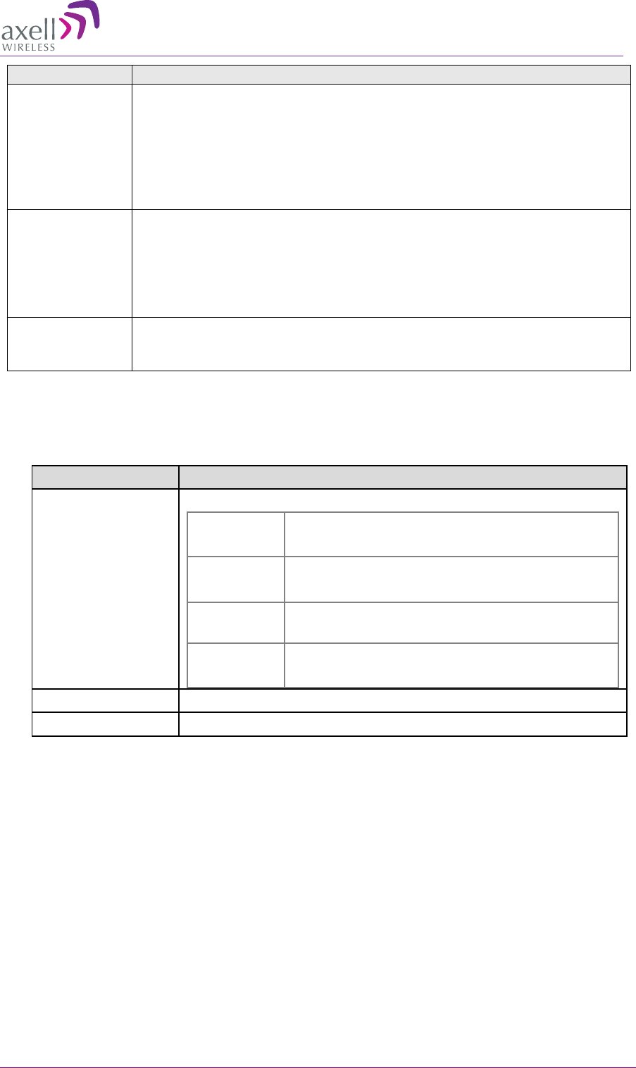
AXELL DIGIMINI- AMERICAS REPEATER
PRODUCT DESCRIPTION AND USER’S MANUAL
© Axell Wireless Ltd DIGImini Americas User Manual Rev 3.5 45
Alarm
Fault and most probable cause and Recommendation
GREEN – normal operation – no oscillations were detected.
RED – oscillations were detected and the system reduced gain in order to
eliminate the oscillations.
Check the Donor and Mobile antenna installations for isolation. After
isolation is within the required levels, the system will automatically increase
gain (since it will no longer affect oscillations and) and the LED will turn
GREEN.
Interferer Power
Exceeded
Indicates if there is any external interference at a level that may affect the
operation of the unit.
Green – low or no interference. Unit operation is not affected.
Red – high external interference that may affect the operation of the unit. It is
recommended to identify the source of the interference and distance the
source or the unit from each other.
RSSI
Fault in the DL or UL path
Most probable cause: caused by a excessively high input signal.
It is recommended to check the LEDs in the Repeater
5.3.2 DIGImini LED Troubleshooting
The DIGImini repeater includes six LEDs on its front panel (see 1.6.1). The following table provides
a description of the LED troubleshooting procedures.
Indicator Description
Band Specific LED
(i.e 900/1800/2100)
One Indicator per band :
RED Steady - service muted due to general fault
Blinking – service muted by user
ORANGE Blinking – service initiating on power up or reset
Steady – high DL/UL signal or VSWR
GREEN and
ORANGE Blinking- Reduced gain by IMOP
GREEN Blinking – DL power below threshold
Steady - normal service operation
(ETHERNET) MNG N/A
(ETHERNET) MODEM
N/A
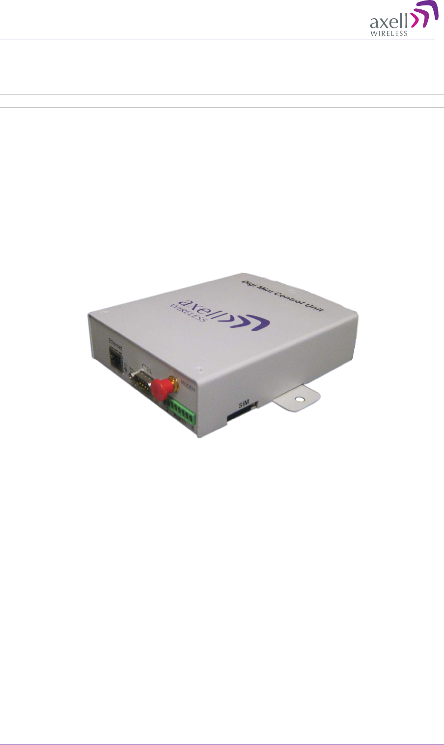
AXELL DIGIMINI- AMERICAS REPEATER
PRODUCT DESCRIPTION AND USER’S MANUAL
46 DIGImini Americas User Manual Rev 3.5 © Axell Wireless Ltd
6 DMCU Installation and Management
NOTE: In case of two cascaded DIGImini repeaters, a single DMCU serves both repeaters.
The DMCU is a separately ordered unit that provides various controls and monitoring functionality,
including: Ethernet access, modem functionality (i.e GSM/GPRS, CDMA) and dry-contact alarms. A
single unit can serve either a single Repeater or a Quad-band assembly comprising of two units.
The DMCU modem antenna is internal, where communication is established with the Repeater via
the external Modem connector at the side of the Repeater.
The DMCU is mounted externally, adjacent to the Repeater, and connected to the Repeater (or to one
of the Repeaters in case of a quad-band repeater assembly) via two cables: RS485 and SMA. The unit
is powered by the Repeater – no power-supply is required.
This section describes the DMCU interfaces, installation procedure and management capabilities
provided by the unit.
Figure 6-1: DMCU
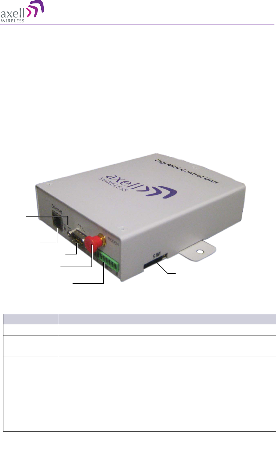
AXELL DIGIMINI- AMERICAS REPEATER
PRODUCT DESCRIPTION AND USER’S MANUAL
© Axell Wireless Ltd DIGImini Americas User Manual Rev 3.5 47
6.1 Features and Capabilities
• Provides complete remote control and monitoring capabilities over GPRS or CDMA, including:
• Remote control via SMS
• Remote alarming through SNMP alarm traps
• Ethernet port for local setup or remote management
• Single unit can support a DIGImini Quad-band installation (two Repeaters)
• No power required – acquires power from repeater
• Dry contact alarms – two external alarms and one summary alarm
• Compact and simple to install
6.2 DMCU Interfaces
Figure 6-2: DMCU Interfaces
Interface Description
Ethernet Ethernet Web session connection for setup.
CTRL Connect to DIGImini Repeater CTRL connector on the side panel.
Modem Connects to the Repeater ANTENNA connector on the Repeater side panel.
Dry Contacts Dry contact connector. See section 6.4.5
SIM
(GPRS only) SIM Card Slot - Applicable only to GSM/GPRS models.
LEDs Band specific – service status
MNG – unit operation status
MDM – modem status
Ethernet
CTRL to DIGImini
Modem to DIGImini
Dry Contacts
SIM
(GPRS Only)
LEDs
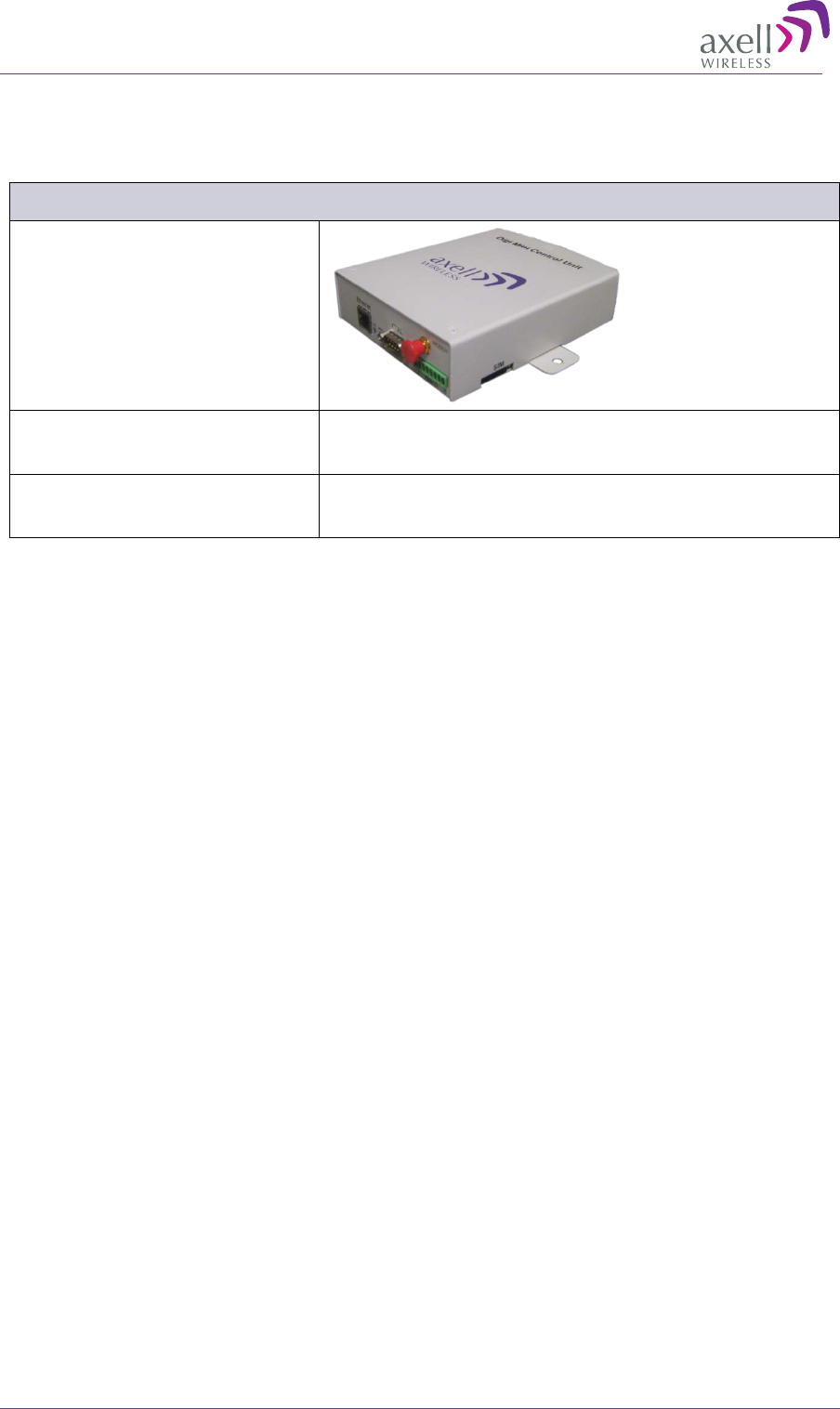
AXELL DIGIMINI- AMERICAS REPEATER
PRODUCT DESCRIPTION AND USER’S MANUAL
48 DIGImini Americas User Manual Rev 3.5 © Axell Wireless Ltd
6.3 DMCU Kit
The following items are provided in the DMCU kit:
DIGImini Controller Kit - Optional
DMCU
RS485 (9 pin) to RS485 9-pin
cable CBL RS485 NO-
X 1.8M MALE/FEMALE GRY
(1579909492)
Controller Modem to Repeater
modem antenna cable
CBL ASSY SMA MALE X2 STR SHLD 1.8M
(CC010B0BA8)
6.4 DMCU Installation Procedure
The DMCU installation procedure slightly varies depending on whether it is a GPRS/GSM or CDMA
modem.
6.4.1 GPRS Modem
1. Insert the SIM card in the side panel slot.
WARNING! This must be performed before connecting the DMCU to the Repeater.
2. Connect the modem to the Repeater.
3. Optional – you may also wire the DMCU dry-contacts.
4. Configure the communication parameters.
6.4.2 CDMA Modem
1. Connect the modem to the Repeater.
2. Optional – you may also wire the DMCU dry-contacts.
3. Activate the Modem (via the Web GUI Direct Modem Access tab).
4. Configure the communication parameters.
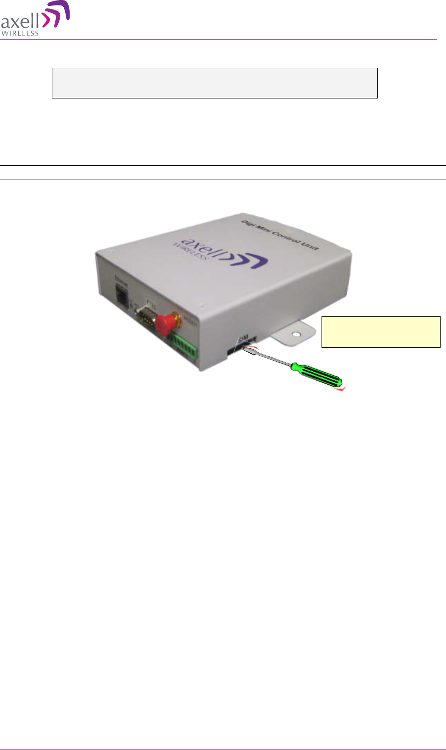
AXELL DIGIMINI- AMERICAS REPEATER
PRODUCT DESCRIPTION AND USER’S MANUAL
© Axell Wireless Ltd DIGImini Americas User Manual Rev 3.5 49
6.4.3 SIM Card Installation (GSM/GPRS Modems only)
WARNING!!! BE SURE TO INSERT THE SIM CARD BEFORE
CONNECTING THE DMCU TO THE REPEATER.
Press the protrusion (yellow button), shown in the
Figure 6-3 below, CONTINUOUSLY until the SIM tray extracts. You may need to use a small sharp
object (do not use a pencil).
Note: This section is not relevant to CDMA modem equipped units. See
6.7.5 CDMA Modem .
Figure 6-3. Insert SIM card
Press to extract SIM tray
and insert SIM card.
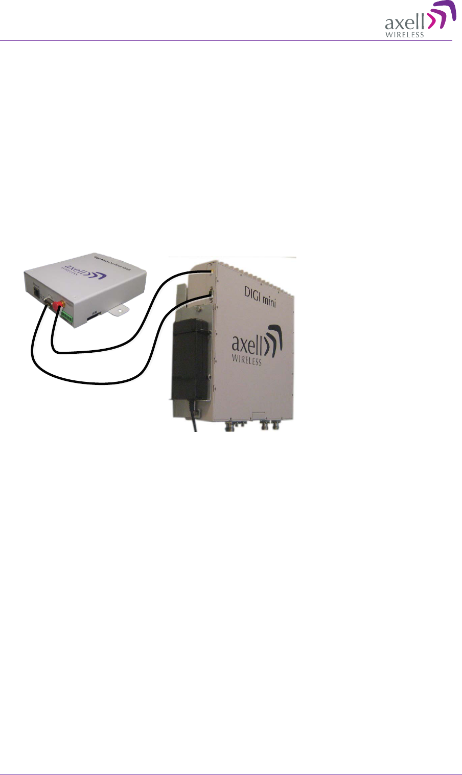
AXELL DIGIMINI- AMERICAS REPEATER
PRODUCT DESCRIPTION AND USER’S MANUAL
50 DIGImini Americas User Manual Rev 3.5 © Axell Wireless Ltd
6.4.4 Connecting the DMCU to the Repeater
To install the DMCU
1. Secure the DMCU to the wall – near the Repeater.
2. Connect the DMCU power converter to an AC power source and to the DMCU.
3. Connect the supplied RS485 to RS485 cable between the CTRL connector of the DMCU and
Repeater (side panel).
4. Connect the supplied cable between the Modem connector of the DMCU and Repeater (side
panel).
5. Optional - connect the dry-contacts according to the instructions in the following section.
Figure 6-4. DMCU Connections
Modem to Modem
CTRL to CTRL
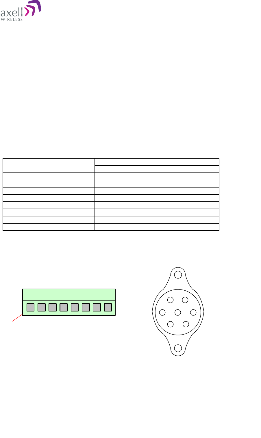
AXELL DIGIMINI- AMERICAS REPEATER
PRODUCT DESCRIPTION AND USER’S MANUAL
© Axell Wireless Ltd DIGImini Americas User Manual Rev 3.5 51
6.4.5 DMCU Dry Contacts
The DMCU provides two types of alarms:
• X2 External Alarms IN – used to acquire status of connected external devices or sensors such as
Door-open, air-conditioner, temperature, etc. These alarms are also defined and enabled through
the GUI. If an alarm is generated, it is displayed in the Alarms Log screen.
• X1 Summary Alarm OUT – indicates a fault in the Repeater. It is activated any time any error is
generated in the Repeater and can be connected to an external device.
To connect and configure the dry-contacts
1. Wire the dry-contacts according to section 6.4.5.1.
2. Configure the external alarms according to section 6.6.3.
3. You may monitor the external alarms log according to section 6.9.1.
6.4.5.1 DMCU Dry-Contact Wiring
Wire color Signal
Pins number
J1
J2
White
Ext Alarm_1 IN
1
1
Brown
GND
2
5
Green
Ext Alarm_2 IN
3
2
Yellow
GND
4
6
Grey
Ext Alarm_3 IN
5
-
Orange
Dry contact Out
6
7
Blue
Dry contact NC
7
4
Red
Dry contact NO
8
3
Connectors view
Figure 6-5. DMCU Dry-Contact Alarms
Cable side view
1
Conn: 1702100004
J1
1
2
34
5
6
7
J2
Cable side view
Conn: 1427000002
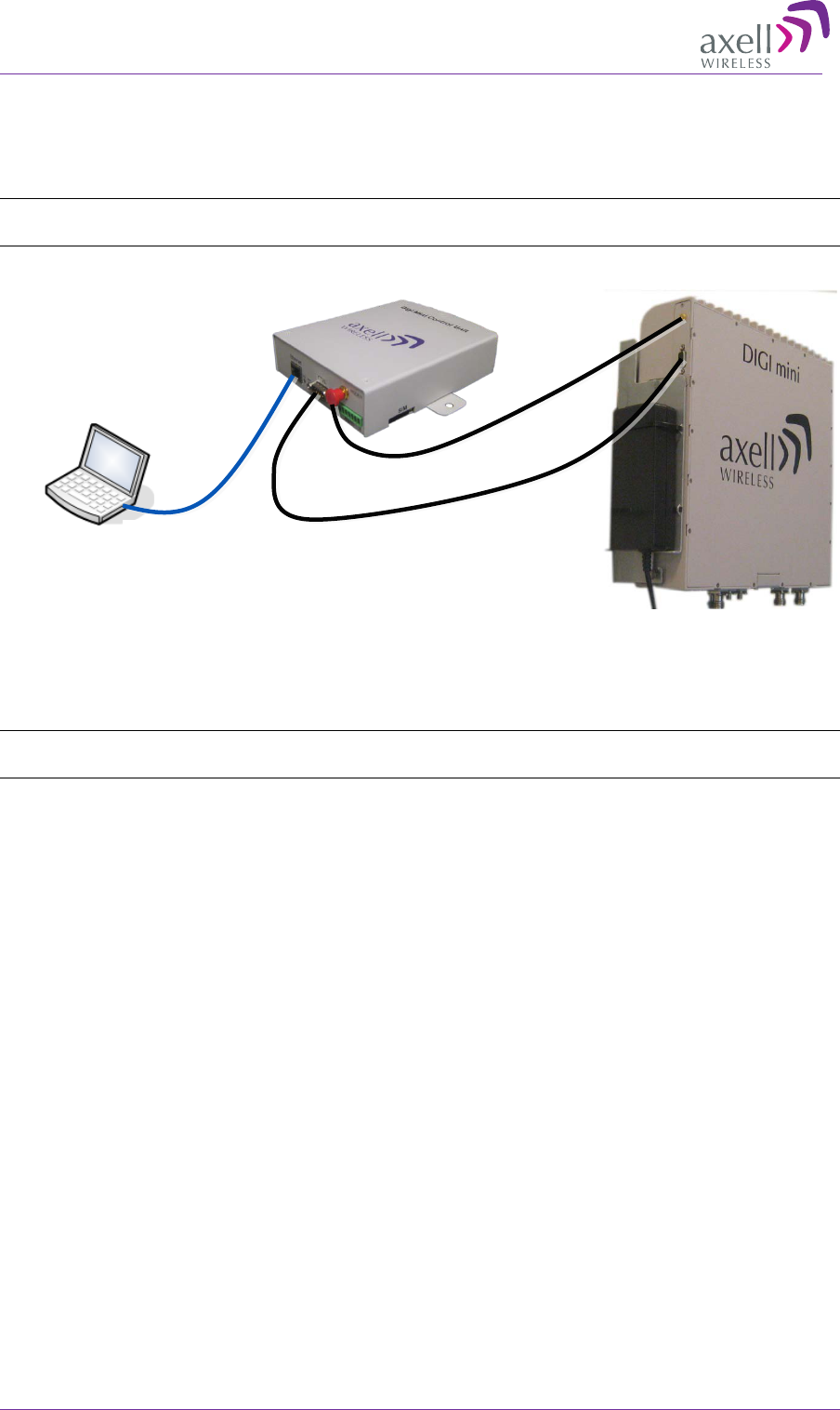
AXELL DIGIMINI- AMERICAS REPEATER
PRODUCT DESCRIPTION AND USER’S MANUAL
52 DIGImini Americas User Manual Rev 3.5 © Axell Wireless Ltd
6.5 Opening a Web Session via the DMCU
Connect the computer and the Control Unit front panel Ethernet port with the supplied cable as
shown below.
NOTE: If connecting the DMCU to a Tri/Quad-band assembly, it may be connected to either of the
two DIGImini units. Local setup will then only be done via the DMCU's ETH port.
Figure 6-6. DMCU Connections
Configure the computer network parameters to communicate with the DMCU.
NOTE: The procedure may vary slightly depending on the operating system installed on your
computer. The following procedure is for Windows 7.
To Configure the Computer’s IP Parameters:
1. Click the Start menu and choose Control Panel.
2. In the Control Panel, click Network and Internet.
3. Click Network and Sharing Center and then click Local Area Connection.
ETH cross-cable
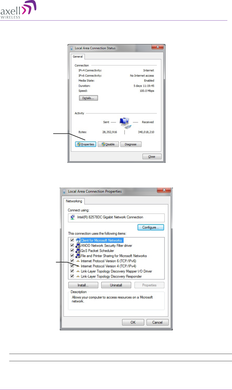
AXELL DIGIMINI- AMERICAS REPEATER
PRODUCT DESCRIPTION AND USER’S MANUAL
© Axell Wireless Ltd DIGImini Americas User Manual Rev 3.5 53
The Local Area Connections Status dialog box appears with the General tab displayed by
default.
4. Click the Properties button (shown above) in the displayed Local Area Connection Status
dialog. The Local Area Connection Properties dialog appears.
5. In the Items list, double-click the “Internet Protocol Version 4 (TCP/IPv4)” item.
6. The Internet Protocol Version 4 (TCP/IPv4) Properties dialog appears.
NOTE: The DMCU is supplied with the default IP address 192.168.1.253.
Properties
button
TCP/IPv4
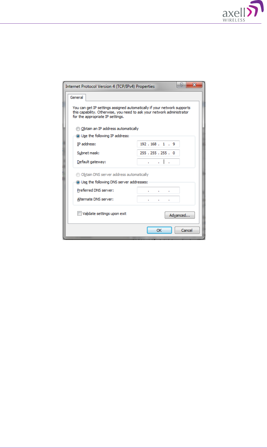
AXELL DIGIMINI- AMERICAS REPEATER
PRODUCT DESCRIPTION AND USER’S MANUAL
54 DIGImini Americas User Manual Rev 3.5 © Axell Wireless Ltd
7. Assign your computer an IP address in the same subnet, in order to communicate with the unit.
• In the IP address area:
• Enter the IP address 192.168.1.x, where ‘x’ can be any number between 2 and 250
inclusive. For example, (192.168.1.9)
• Define the subnet mask as shown (255.255.255.0)
• Click OK. The computer communication parameters are now defined and you can
open a session to the Repeater.
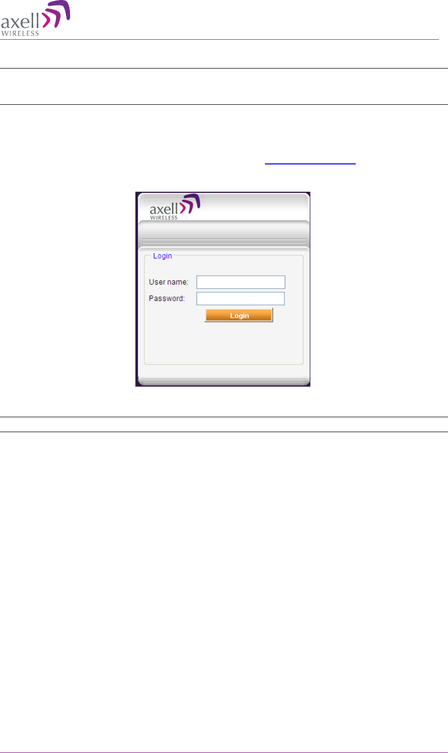
AXELL DIGIMINI- AMERICAS REPEATER
PRODUCT DESCRIPTION AND USER’S MANUAL
© Axell Wireless Ltd DIGImini Americas User Manual Rev 3.5 55
6.5.1 Login to the Repeater
NOTE: The Repeater is factory assigned the address 192.168.1.253. Initial login is performed using
this address; however it is recommended to make the necessary modifications according to
information provided by your network administrator.
To login to the Repeater
1. Open one of the Flash-enabled browsers listed in the system requirements.
2. In the address line, enter the IP address of the Repeater. http://192.168.1.253. A session will be
established with the Repeater an the login dialog appears.
3. Type the default User Name admin and the default Password admin.
Note that both are case sensitive and must be entered with lower case letters.
4. Click Login. The application main window appears.
5. Quickly review the following section describing the application window and then proceed to
configure the signal levels according to section 5.2.3.
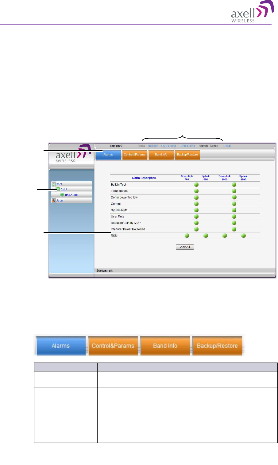
AXELL DIGIMINI- AMERICAS REPEATER
PRODUCT DESCRIPTION AND USER’S MANUAL
56 DIGImini Americas User Manual Rev 3.5 © Axell Wireless Ltd
6.5.2 Navigating the Web GUI Application
When a session is opened via the DMCU, all the available management capabilities are displayed.
The Web Access interface provides three groups of options, listed in the left side Topology Tree
items:
• CMU – system control level options. These include communication parameters, alarms log,
external alarms configuration options and more.
• Band (e.g. 850-1900) – band specific RF parameters control and monitoring options. The
displayed bands depend on the supported configuration: Single, Dual, Triple or Quad band
configuration.
• Users – Provides user administration options and enables changing user passwords.
Figure 6-7. Example of Web GUI Screen (shows dual-band)
6.5.2.1 Band Tabs
The band pane and tabs are accessed by clicking on the band item (e.g. 850-1900) in the topology
tree. The upper area of each selected pane shows the tabs corresponding to that pane.
Item
Description / Values
Alarms
Displays various alarms generated by the Repeater and enables
monitoring (see detailed description in section 5.3.1).
Control and Params
Used for adjusting RF parameters and channel configuration
(signal level, gain and bandwidth). See detailed description in
section
5.2.6).
Band Info
Shows information on the selected band, including valid
definable bandwidth pre sub-band. See section 5.2.5.
Backup/Restore
Configuration files management options (configuration files
can be stored on the Repeater for access). See section 6.8.3.
Topology
Tree Items
Pane related to
selected tree
item
Tabs related to
selected Tree
item
Operation buttons
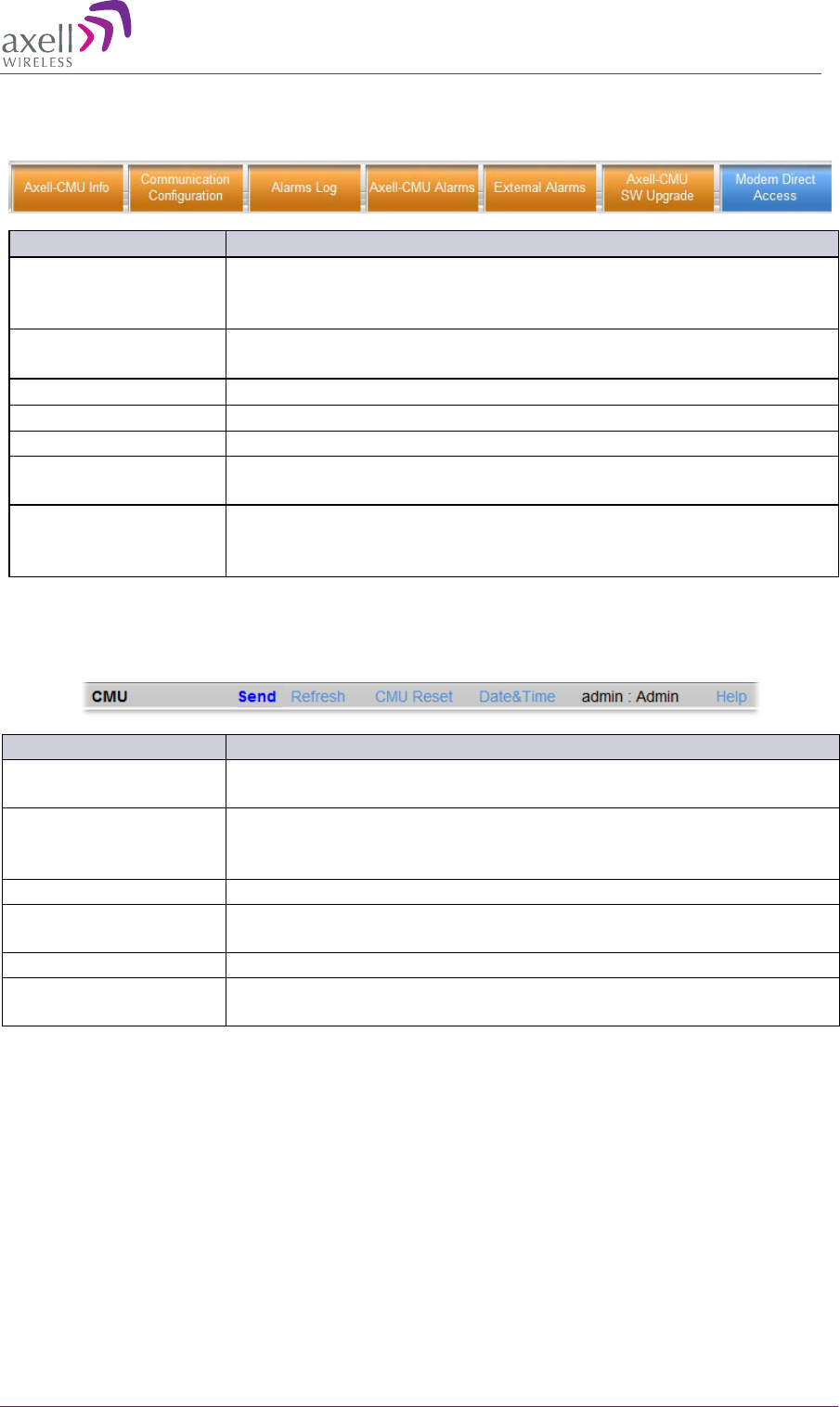
AXELL DIGIMINI- AMERICAS REPEATER
PRODUCT DESCRIPTION AND USER’S MANUAL
© Axell Wireless Ltd DIGImini Americas User Manual Rev 3.5 57
6.5.2.2 CMU Tabs
The DMCU tabs and options are accessed by clicking on the CMU item in topology tree.
Item
Description / Values
Axell CMU Info
Provides HW and SW version information, Repeater name definition
options and enables setting the minimum alarm log level. See section
6.8.1.
Communication
Configuration
Used to set IP, SNMP and SMS destinations, and modem
communication parameters. See detailed description in section 6.7.
Alarms Log
Log of past and current alarms. See description in section 6.9.1.
Axell-CMU Alarms
Shows any generated external alarms.
External Alarms
Used to define any connected external alarms. See section 6.6.3.
Axell-CMU SW
Upgrade
Enables upgrading the CMU. See section 6.8.2.
Modem Direct Access
Used to troubleshoot GPRS/CDMA modem activation by sending the
appropriate commands and viewing responses and used to activate
CDMA modem. See section
6.7.5.1
6.5.2.3 Operation Buttons
The following Operation buttons are available.
Item
Description / Values
Selected Tree Item
Shows the currently selected topology tree item.
Values: CMU, Band (e.g. 850-1900), Users
Send
Click after completing the new data input and values update in any
screen in order to insert the new values into the Repeater, and
implement the changes
Refresh
Click to refresh the current screen and update the displayed data
CMU Reset
Click to reset the Web Access application, in case of failure or display
problems
Date and Time
Displays Date & Time as set in the Repeater
Help
Click Help to display an e-guide line for the system operation. This
Help is general by its nature and some features may not be included.
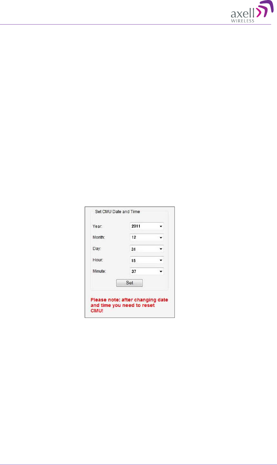
AXELL DIGIMINI- AMERICAS REPEATER
PRODUCT DESCRIPTION AND USER’S MANUAL
58 DIGImini Americas User Manual Rev 3.5 © Axell Wireless Ltd
6.6 Basic Configuration Procedures
Begin by performing the following procedures:
• Configure Signal levels and Channels
• Set the Date and Time
• If external alarms have been connected – enable the external alarms
6.6.1 Configuring Signal Levels and Channels
For signal level and channel configuration refer to Chapter 5.2.3 - Signal Levels and Channel
Configuration.
6.6.2 Setting Date and Time
It is important to set the correct date and time on the unit since this provides the timestamp for each
logged event and alarm.
To set the Repeaters date and time
1. Click on CMU in the tree pane.
2. Click on Date & Time in the menu bar. The following dialog appears.
3. Set the date and time parameters and click on Set.
4. Reset the CMU (as described in the following section).
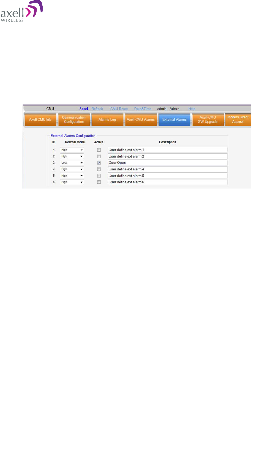
AXELL DIGIMINI- AMERICAS REPEATER
PRODUCT DESCRIPTION AND USER’S MANUAL
© Axell Wireless Ltd DIGImini Americas User Manual Rev 3.5 59
6.6.3 Configuring the External Alarms
Any connected alarms (section 6.4.5) must be enabled and configured according to the instructions
provided in this section.
To configure external alarms
1. Click on CMU in the tree pane.
2. Click the External Alarms tab. The following dialog appears.
3. For each connected alarm:
• Checkmark the Active checkbox.
• Set the alarm Normal Mode as High or Low.
• In the Description field, assign the alarm an identifiable name.
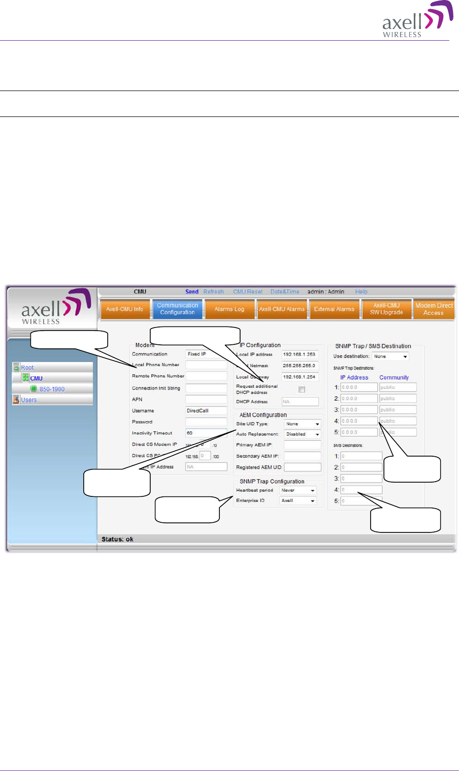
AXELL DIGIMINI- AMERICAS REPEATER
PRODUCT DESCRIPTION AND USER’S MANUAL
60 DIGImini Americas User Manual Rev 3.5 © Axell Wireless Ltd
6.7 Communication and System Parameters
NOTE: All CMU Configuration options (tabs visible in screenshot below) require a CMU be connected
to the DIGImini Repeater. If a CMU is not connected the GUI will not display the CMU tab.
The Communication Configuration tab provides the Modem, IP, AEM and SNMP trap configuration
parameters.
This section describes how to access the dialog. The following sub-sections provide detailed
information on each configuration option.
6.7.1 The Communication Configuration Tab
To access the Communication Configuration tab
In the left tree pane, click CMU. From the available tabs in the work area, choose the
Communication Configuration tab.
6.7.2 IP Address Configuration
The Repeater supports both Static and DHCP addresses. A unique technology enables applying both
types to the same Ethernet port. Both addresses may enable local and remote management.
• Local IP Address – Static IP assigned by the user to the system. The default Static IP address is
192.168.1.253. It is highly recommended to preserve this setup. In case of a change, make sure
you record the newly assign IP.
• DHCP Address – address assigned by DHCP server – used for remote management via an
Ethernet connection.
IP Address settings
Modem parameters
SNMP IP
destinations
Trap sending
frequency
SMS destinations
mobile numbers
AEM
configuration
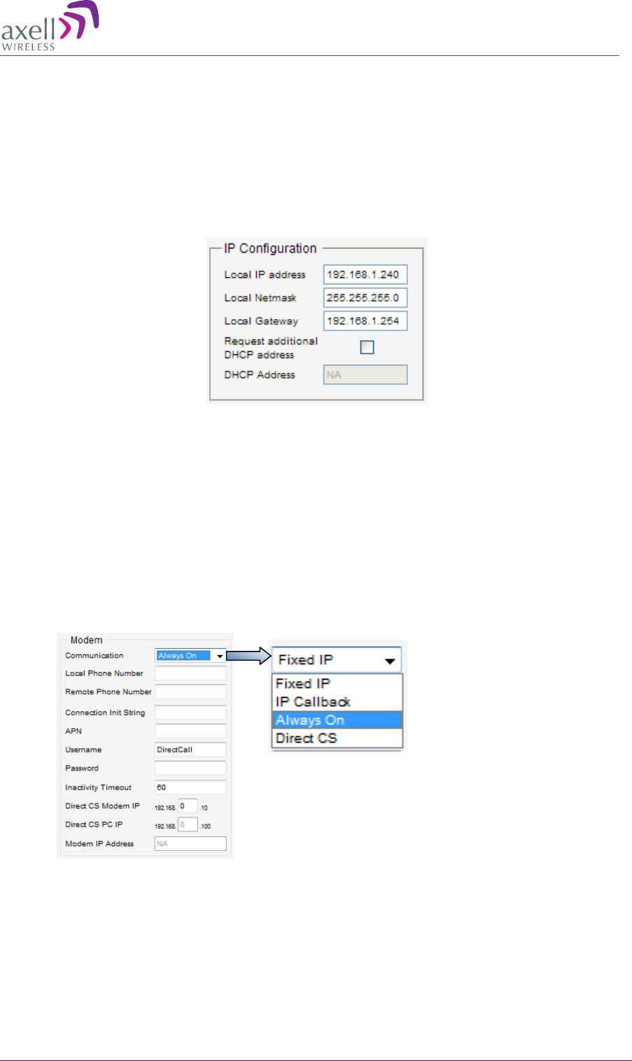
AXELL DIGIMINI- AMERICAS REPEATER
PRODUCT DESCRIPTION AND USER’S MANUAL
© Axell Wireless Ltd DIGImini Americas User Manual Rev 3.5 61
To assign the unit IP address
1. Click the CMU tree item and then click the Communication Configuration tab.
2. To assign the unit addresses:
• Local IP address - in the IP Configuration area, assign the unit the IP address,
Netmask and Gateway parameters provided by your system administrator.
• DHCP server address – checkmark the option Request Additional DHCP Address.
The assigned address can be seen in the DHCP Address field.
6.7.3 General Modem Parameters
This section describes the available modem parameters. Specific procedures for GSM/GPRS modem,
CDMA modem or for Direct CS are described in the relevant sections.
To define the modem parameters
1. Click CMU in the left tree pane and select the Communication Configuration pane.
2. In the Modem area, select the Communication mode and define any additional parameters
according to the table below. (Any defined fields in the figure below are only an example!)

AXELL DIGIMINI- AMERICAS REPEATER
PRODUCT DESCRIPTION AND USER’S MANUAL
62 DIGImini Americas User Manual Rev 3.5 © Axell Wireless Ltd
In the communication
field, select … For this communication mode.
Fixed IP Modem OFF
Always ON
Packet Switch mode.
Additional parameters: Also (depending on the configuration
required by your operator), define the Connection Init string,
APN, User Name and Password.
NOTE: After the modem connects to the network, the Modem
IP Address is displayed.
Direct CS
Direct Circuit Switch. (See section 6.7.7
for details on
opening a Direct CS session to the repeater.)
Additional parameters: Also (depending on the configuration
required by your operator), define the Connection Init string,
User Name, Password and Direct CS Modem IP (an internal
address used for Web surfing).
IP Callback Special mode for specific installation types.
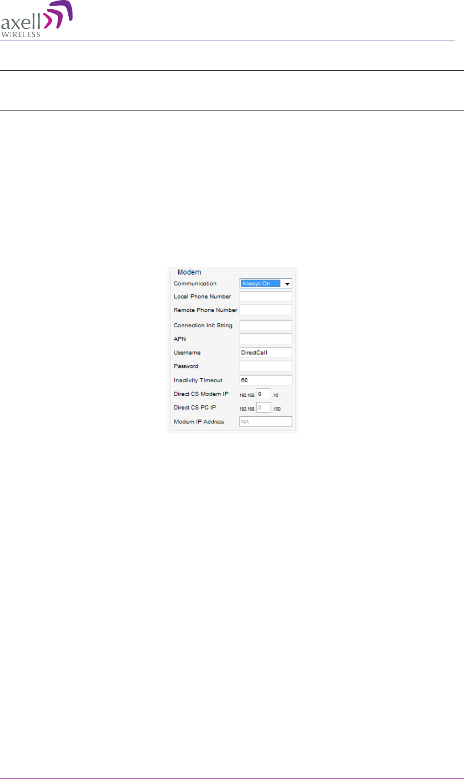
AXELL DIGIMINI- AMERICAS REPEATER
PRODUCT DESCRIPTION AND USER’S MANUAL
© Axell Wireless Ltd DIGImini Americas User Manual Rev 3.5 63
6.7.4 GSM/GPRS Modem Setup
NOTE: It is assumed that the SIM card is already installed according to section
6.4.3. If the modem
does not respond properly, troubleshoot the modem via the Direct Access tab described in section
6.7.6).
This GSM/GPRS Modem setup consists of configuring the Modem communication parameters via
the Communication Configuration tab.
To define the GSM/GPRS modem Communication parameters
1. Click CMU in the left tree pane and select the Communication Configuration pane.
2. In the Modem area, select the Communication mode as Always On and define any additional
parameters according to the table below. (Any defined fields in the figure below are only an
example!)
3. If the modem does not run, troubleshoot using the Modem Direct Access Tab (section 6.7.6).
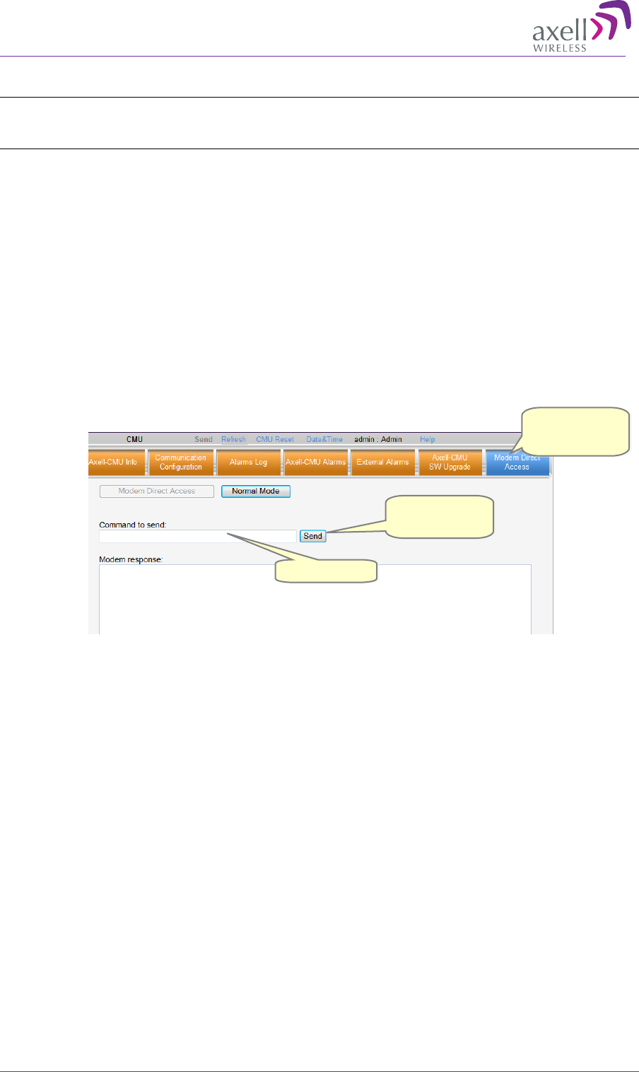
AXELL DIGIMINI- AMERICAS REPEATER
PRODUCT DESCRIPTION AND USER’S MANUAL
64 DIGImini Americas User Manual Rev 3.5 © Axell Wireless Ltd
6.7.5 CDMA Modem Setup
NOTE: This procedure describes how to configure the CDMA modem for operation in a Verizon
network. For operation in other network, consult your Axell Wireless service personnel for
instructions.
This procedure for Verizon network setup consists of the following phases:
• Modem Activation and verification – via the Modem Direct Access tab
• Configuring Modem communication parameters – via the Communication Configuration tab
• If the modem does not respond properly, troubleshoot the modem via the Direct Access tab
described in section 6.7.6).
6.7.5.1 Activating Modem on the CDMA Network
For the modem to connect over a CDMA network, it must first be activated according to the
following procedure:
To activate modem CDMA functionality
1. Click CMU in the left tree pane and select the Modem Direct Access tab.
2. Click on the Modem Direct Access button. The Command to send text-box and Send button will
be available for entering commands.
3. Perform the following command sequence:
• Type the command ATD*22899; (including the semicolon) and click Send.
• Wait 10 seconds and then type the command AT and click Send. The following set of
responses should appear in the Modem Response area:
+WOT1: “Programming in Progress”
+WOTS: “SPL unlocked”
+WOTP: “PRL download OK”
+WOTM: “MDM download OK”
+WOTC: “Commit successful”
+WOT2: “Programming Successful!”
4. If “Programming Successful!” does not appear, verify RSSI and modem registration according to
the procedures in section 6.7.6.
5. Click on the Normal Mode button or on CMU Reset in the command bar for changes to take
effect.
ATD*22899;
Click Modem
Direct Access
Click Send
after
each command
Enter command
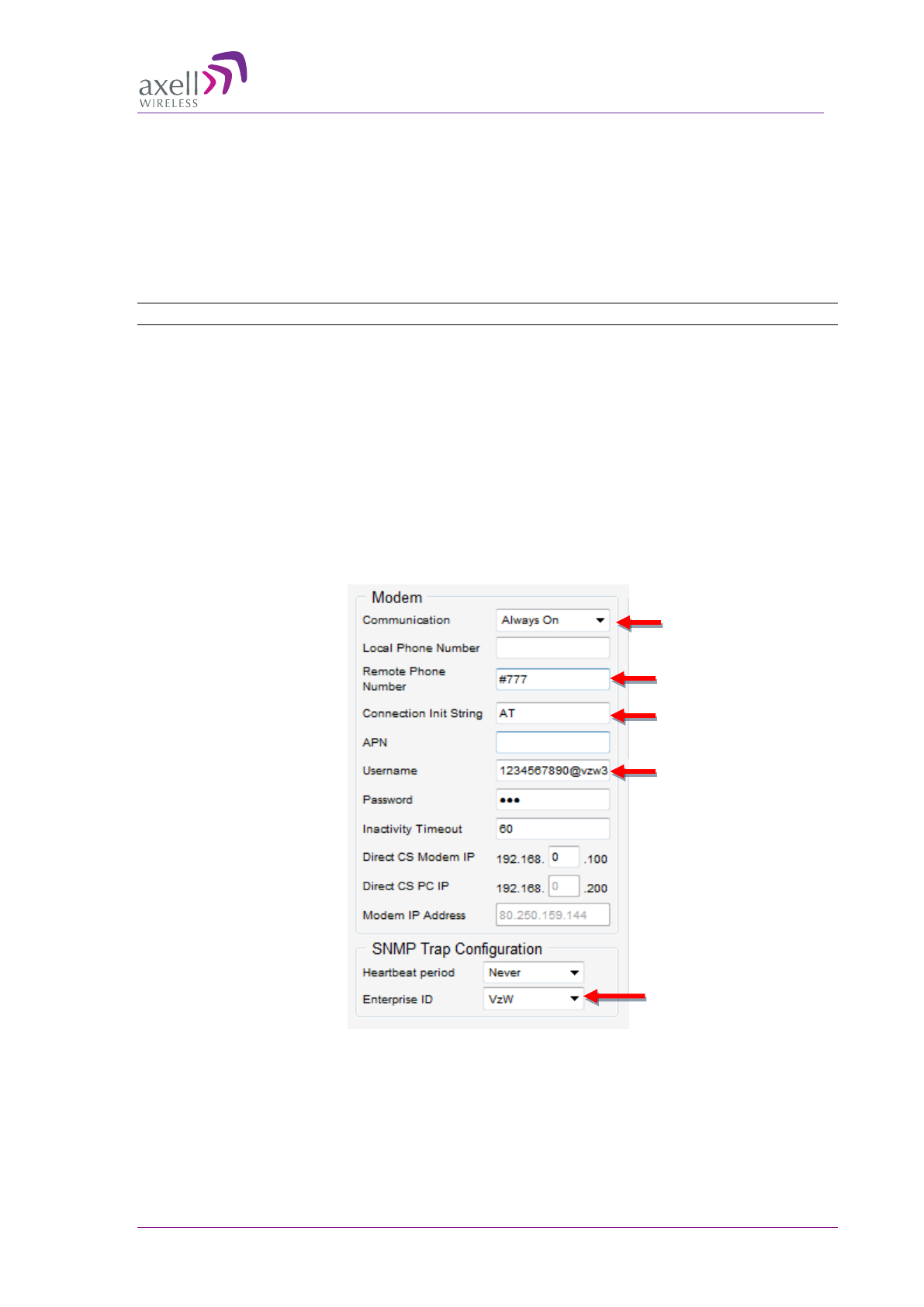
AXELL DIGIMINI- AMERICAS REPEATER
PRODUCT DESCRIPTION AND USER’S MANUAL
© Axell Wireless Ltd DIGImini Americas User Manual Rev 3.5 65
6. After a few minutes, a Modem IP Address should appear on the CMU GUI screen. This indicates
the modem is functioning on the CDMA Network. If the modem does not respond properly,
troubleshoot the modem via the Direct Access tab described in section 6.7.6).
6.7.5.2 Configuring Modem Communication Parameters
To configure the CDMA VERIZON modem communication parameters
NOTE: For other operators, consult with your Axell Wireless customer support.
1. In the left pane, click CMU and choose the Axell CMU Configuration tab.
2. In the Modem area, define the parameters as follows:
• Modem Communication = Always On
• The Remote Phone Number = #777
• Connection Init String = AT
• User Name = 1234567890@vzw3
• Enterprise ID parameter = VZW
3. In the SNMP Trap Configuration field area, enter the system identification name

AXELL DIGIMINI- AMERICAS REPEATER
PRODUCT DESCRIPTION AND USER’S MANUAL
66 DIGImini Americas User Manual Rev 3.5 © Axell Wireless Ltd
6.7.6 Verifying Modem RSSI and Registration
Use the following AT modem commands to verify the RSSI level and the modem Registration to
better troubleshoot failure of the modem. Any other standard AT commands may be used as well.
NOTE: The AT commands described in this section are standard commands and more information
may be acquired from any standard source.
1. Click CMU in the left tree pane and select the Modem Direct Access tab.
2. Click on the Modem Direct Access button. The Command to send text-box and Send button will
be available for entering commands.
3. To verify RSSI level (Received Signal Strength Indicator):
• In the Modem Direct Access tab, Command to Send area, type: AT+CSQ and click Send.
• Response: +CSQ <rssi>,<ber>
<ber> is not relevant (ignore)
<rssi> should be larger than 10, and NOT equal to 99 (rssi>10 & rssi≠99)
4. To verify modem Registration status, in the Modem Direct Access tab, Command to Send area:
• Type: AT+CREG? and click Send.
• Response:
+CREG
<param1>,<param2>
(note that is not relevant).
<
param1
> is not relevant (ignore)
<param2>
should be either 1 (Registered) or 5 (roaming)
6.7.7 Direct Circuit Switch Connection
A. On the Repeater, set the Repeater Modem parameters as follows:
• Communication - Direct CS
• To provide security, set the User Name and Password for the repeater (the same User
Name and Password will be defined on the dial-up connection).
• You may modify (optional) the Direct CS Modem IP – this is the Web address used to
open a Repeater session. Otherwise, the default displayed value can be used.
B. On your computer, set up a dial-up connection as follows:
1. Via Network Connections, create a Dial-up connection on your computer (Connect using a dial-
up modem). The procedure may vary slightly depending on your Operating System.
2. Define the parameters as follows:
Click Modem
Direct Access
Click
Send after
each command
Enter command

AXELL DIGIMINI- AMERICAS REPEATER
PRODUCT DESCRIPTION AND USER’S MANUAL
© Axell Wireless Ltd DIGImini Americas User Manual Rev 3.5 67
• ISP connection name – user defined, recognizable name for this connection for future
reference.
• Phone Number – the number corresponding to the number assigned to the SIM card
installed on the Repeater.
• User Name and Password – the User Name and Password (if assigned) that you
allocated in the Modem parameters in the Communication dialog (see previous
section).
C. Open a session to the Repeater:
1. On your computer, click the relevant dial-up connection item or the icon, to open a dial-up route
to the Repeater.
2. Open a Web Browser and enter the Direct CS Modem IP that is defined in the Modem
parameters on your Repeater. A session will be opened to the Repeater.
6.7.8 Configuring Notification Method - SNMP Trap or SMS
The Repeater can be configured provide fault notification either by sending traps to defined IP
addresses or by sending an SMS message to configured destinations (only one option can be
selected).
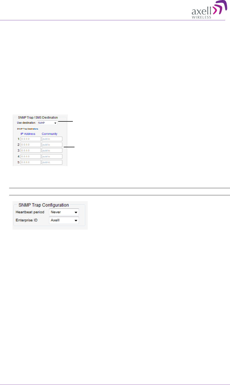
AXELL DIGIMINI- AMERICAS REPEATER
PRODUCT DESCRIPTION AND USER’S MANUAL
68 DIGImini Americas User Manual Rev 3.5 © Axell Wireless Ltd
6.7.8.1 Configuring SNMP Trap Destinations
You may configure traps to be sent to five destination addresses each time a fault is triggered. The
traps are sent at the defined heartbeat frequency.
To set SNMP Trap Destination parameters
1. In the Use Destination field, select the SNMP option
2. For each destination:
• Enter the IP Address (where the IP addresses should be in the same subnet as the
repeater).
• Define the Community names (default = public) of the computers to which traps will
be sent.
3. In the SNMP Trap Configuration area, in the Heartbeat Period field, define the frequency (in
minutes) at which traps will be sent.
NOTE: It is recommended to maintain the Enterprise ID as Axell.
4. Click Send.
Select SNMP option from
drop-down list
Define up to five SNMP
destination addresses
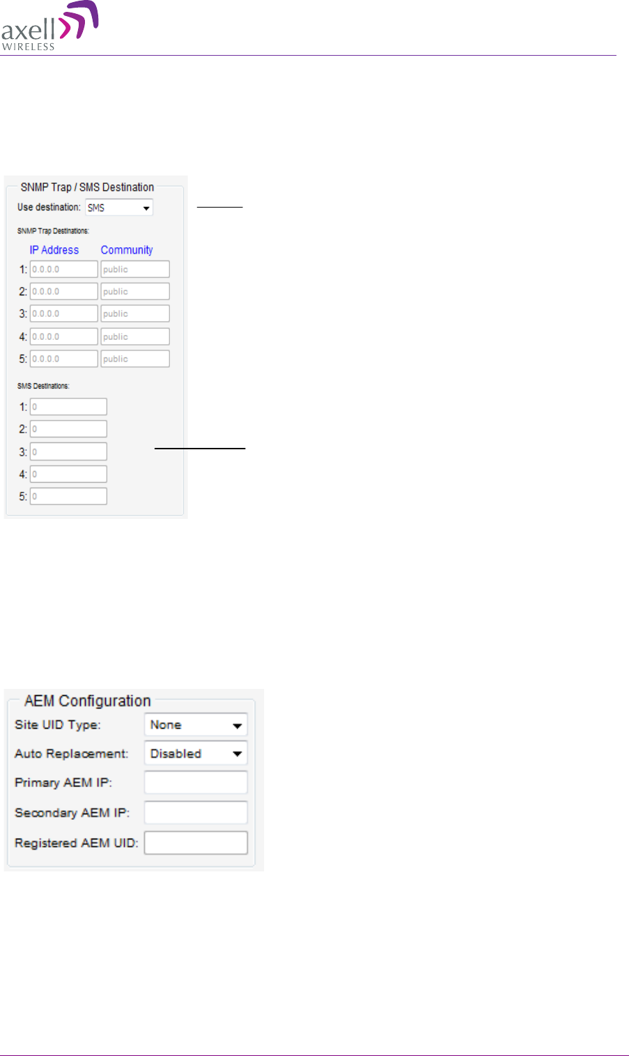
AXELL DIGIMINI- AMERICAS REPEATER
PRODUCT DESCRIPTION AND USER’S MANUAL
© Axell Wireless Ltd DIGImini Americas User Manual Rev 3.5 69
6.7.8.2 Configuring SMS Notification Destinations
You may configure up to five SMS destinations (mobile numbers).
To set SMS Destination parameters
1. In the Use Destination field, select the SMS option from drop-down list.
2. Define up to five SMS destinations (for example, + xxx541234567):
3. Click Send.
6.7.8.3 AEM (Axell Element Manager) Configuration
Configure the AEM parameters provided by the system administrator so that the 3021D Repeater is
integrated in the network and can be centrally managed.
Define the SMS destinations
(mobile numbers)
Select SMS option from
drop-down list
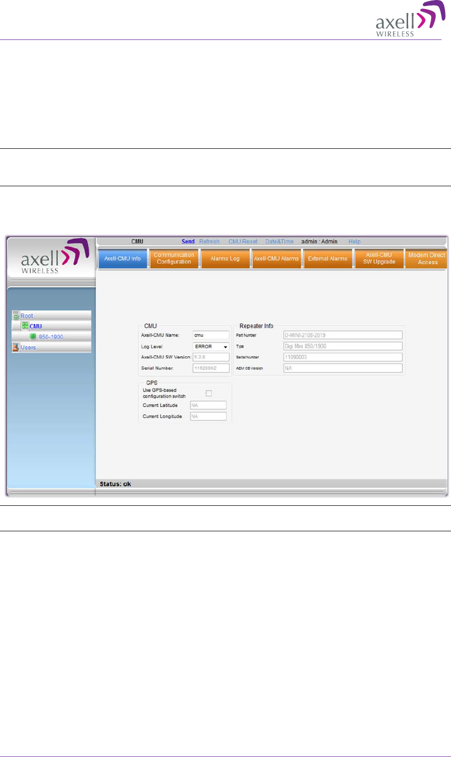
AXELL DIGIMINI- AMERICAS REPEATER
PRODUCT DESCRIPTION AND USER’S MANUAL
70 DIGImini Americas User Manual Rev 3.5 © Axell Wireless Ltd
6.8 DMCU Administration
6.8.1 Viewing Repeater Level Information
Use the CMU-Info screen to view the hardware and software versions of the DIGImini Repeater. In
addition, the screen provides configuration options for setting the minimum Log Level and assigning
the Repeater a recognizable name.
NOTE: Read-only or irrelevant parameters are grayed out.
NOTE: Usually, these fields are grayed-out. Grayed-out fields indicate that the display is Read-only.
Active fields indicate that the parameter values can be defined.
To access the Repeater Information window
1. From the Tree Pane, CMU and choose the Axell-CMU Info tab.
NOTE: The Axell-CMU Name field can be used to assign the module a recognizable name
corresponding to the technology.
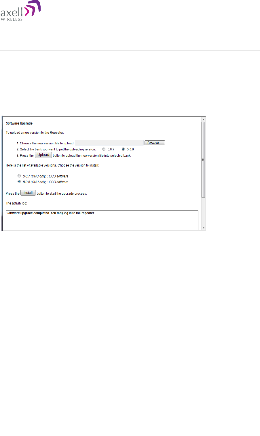
AXELL DIGIMINI- AMERICAS REPEATER
PRODUCT DESCRIPTION AND USER’S MANUAL
© Axell Wireless Ltd DIGImini Americas User Manual Rev 3.5 71
6.8.2 CMU Software Upgrade
The procedure described in this section is used to upgrade the repeater CMU.
NOTE: This procedure is performed for every new management version.
To Upgrade the Repeater SW
1. From the Tree Pane, select CMU.
2. Select the Axell CMU SW Upgrade tab. The CMU SW Upgrade screen shown below appears.
3. Choose the version to upload and perform the procedure according to the instructions on the screen.
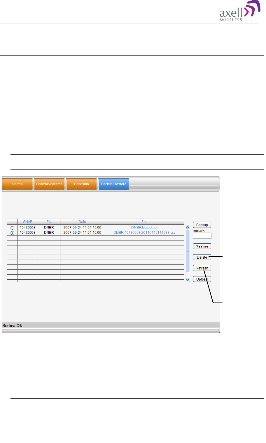
AXELL DIGIMINI- AMERICAS REPEATER
PRODUCT DESCRIPTION AND USER’S MANUAL
72 DIGImini Americas User Manual Rev 3.5 © Axell Wireless Ltd
6.8.3 Backup/Restore of Repeater Configuration
NOTE: Backup and Restore procedures are only applicable for web sessions opened via the DMCU
(see
6.5 and
6.5.1) as opposed to directly through the Repeater (see
5.1).
The DIGImini Web GUI management application enables the backup and restore of the repeater
configuration files. This section provides a description of the following procedures:
• Backup of current Repeater configuration
• Restoring previous Repeater configuration from available files
• Uploading new configuration file from computer
• Saving configuration settings to other location (i.e. computer)
To access Backup/Restore tab
1. From the Tree Pane, select the band item.
2. Select the Backup/Restore tab. The following tab appears.
NOTE: The following figure is only an example of the Backup/Restore tab and does not show
DIGImini values.
6.8.3.1 Backup of Repeater Configuration
To perform backup procedure
1. To assign the configuration file a recognizable name, enter a name in the remark field.
NOTE: This must be performed before performing the backup operation; otherwise the file will
automatically be assigned a name according to the backup date and unit ID.
The name cannot be modified once the backup has been performed.
2. Click the Backup button located on the right-hand side of the tab.
3. The file will be added to the table displayed in the Backup/Restore tab.
Select file
from list and
click Delete to
remove.
Click Refresh
to list of
available
configuration
files
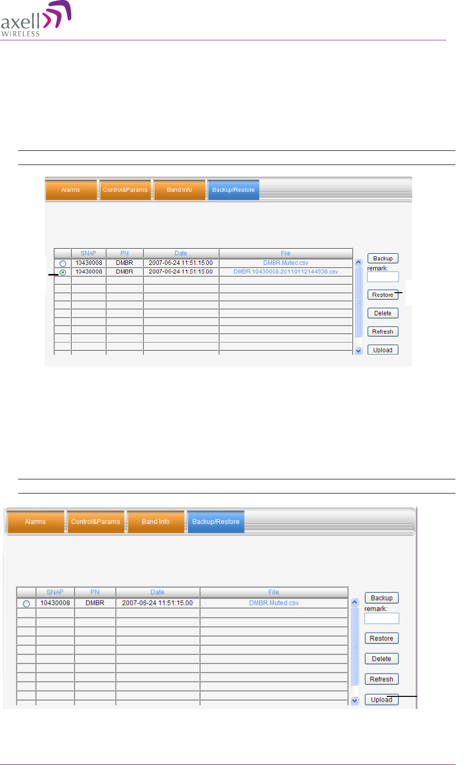
AXELL DIGIMINI- AMERICAS REPEATER
PRODUCT DESCRIPTION AND USER’S MANUAL
© Axell Wireless Ltd DIGImini Americas User Manual Rev 3.5 73
6.8.3.2 Restoring Previous Repeater Configuration
To restore previous configuration
1. Select the required configuration file (enable corresponding radio button) from the available list
in the Backup/Restore tab.
2. Click the Restore button.
NOTE: The following figure is only an example of the Backup/Restore tab.
3. Click on the Control and Params tab and verify that the required configuration settings have
been restored.
6.8.3.3 Uploading New Configuration File to Repeater
To upload configuration file to Repeater
1. Click the Upload button.
NOTE: The following figures are only an example of the Backup/Restore tab.
2. Select the file from the Browse dialog and click Open.
Selected
config
file
Restore
button
Upload
button
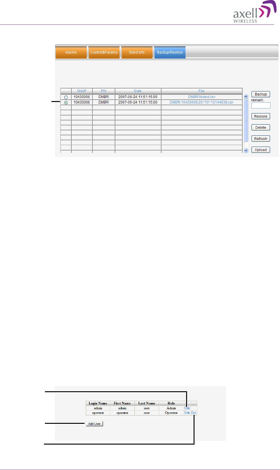
AXELL DIGIMINI- AMERICAS REPEATER
PRODUCT DESCRIPTION AND USER’S MANUAL
74 DIGImini Americas User Manual Rev 3.5 © Axell Wireless Ltd
3. The file appears in the list displayed in the Backup/Restore table.
6.8.3.4 Saving Configuration File to Computer
To save a configuration file from the available list in the Backup/Restore table to a location in a
connected computer:
• Select file from list.
• Click the link in the File column.
• Select the location in the Browse dialog.
6.8.4 User Management
This section describes how to perform the user management operations. By default, two users
belonging to one of three authentication levels are defined on the Repeater.. You may add new users,
modify or delete existing users.
6.8.4.1 User Levels
Three user levels are available:
• Admin – has access to all administration and configuration options, including user management.
(Default Password admin and default User Name admin.)
• Operator – has access to all configuration options except for the Users list or the Loaders screen.
6.8.4.2 Viewing the List of Defined Users
To display the User Administration pane
From the Tree Pane, select Users. The list of users is displayed in the Configuration Pane according
to the identifying information and authentication level (Role).
Edit user
Delete user
Add user
Added config
file
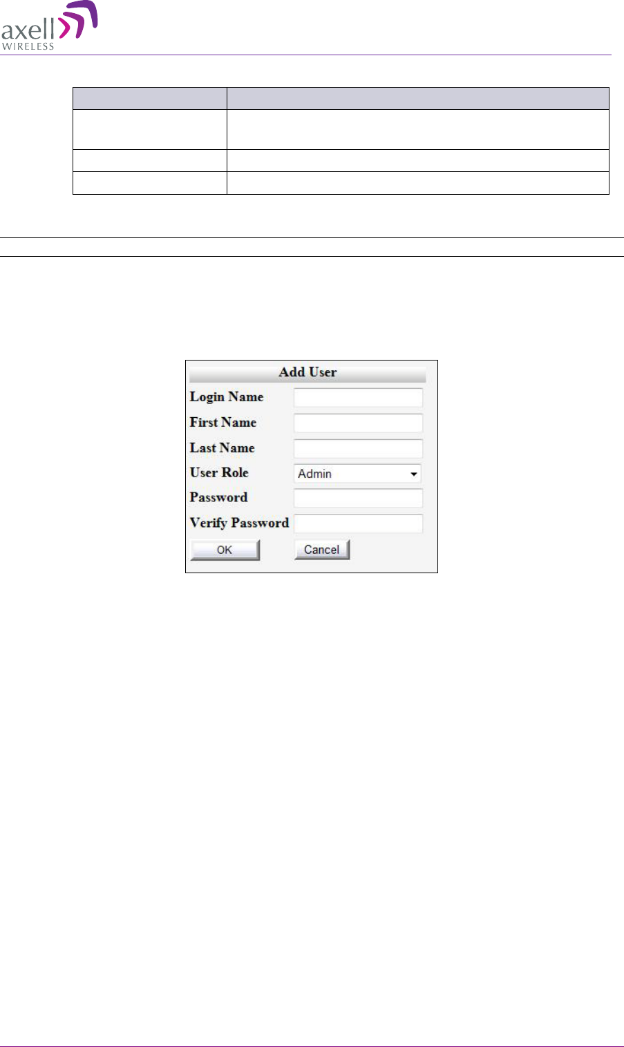
AXELL DIGIMINI- AMERICAS REPEATER
PRODUCT DESCRIPTION AND USER’S MANUAL
© Axell Wireless Ltd DIGImini Americas User Manual Rev 3.5 75
The following table provides a description of the Users dialog options.
Option Description
Add User (button) Adds a new user with to user defined access level and
password.
Del(ete) Deletes a selected user from the list.
Edit Enables changing the definitions of an existing user.
6.8.4.3 Adding Users
NOTE: User name and password entries are case sensitive.
To add a user
1. From the Tree Pane, select Users. The list of users is displayed in the User's Pane.
2. From the User's Pane, click Add User. The Add User dialog box is displayed.
3. Enter the Login Name – name used by user to login.
4. Type the user's First Name and Last Name – used to identify the user.
5. Select the User Role – access level. This defines the operations that the user will be able to
perform.
6. Enter the Password and in Verify Password enter the password again for verification.
7. Click OK.
6.8.4.4 Editing a User
To modify user definitions
1. From the Tree Pane, select Users. The list of users is displayed in the User's Pane.
2. Select the User to be edited in the list.
3. Click Edit. The user definitions dialog appears.
4. Make the required changes and click OK.
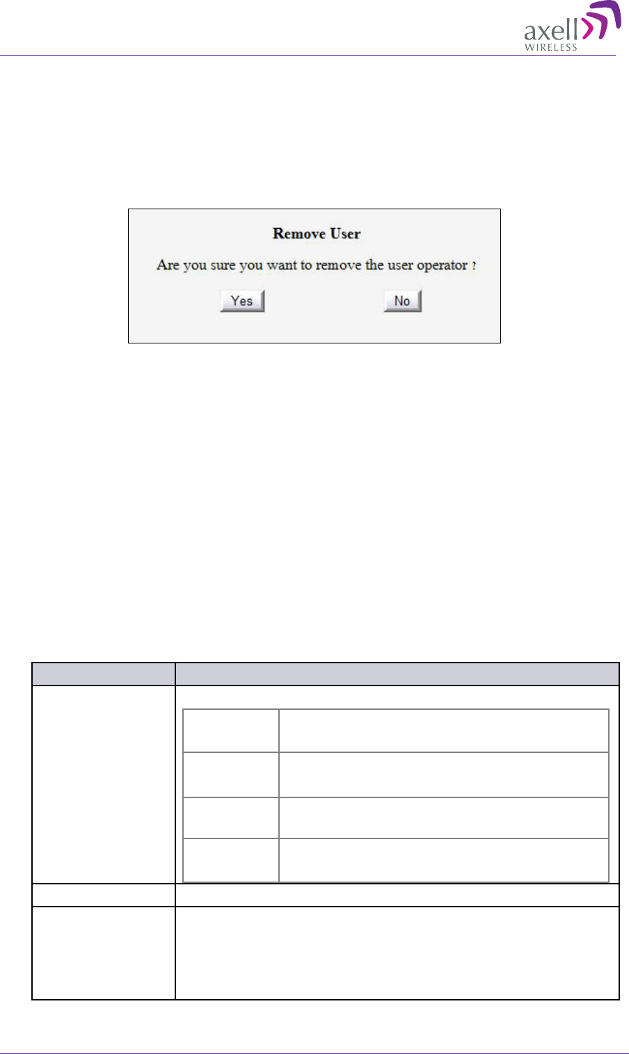
AXELL DIGIMINI- AMERICAS REPEATER
PRODUCT DESCRIPTION AND USER’S MANUAL
76 DIGImini Americas User Manual Rev 3.5 © Axell Wireless Ltd
6.8.4.5 Deleting a User
To delete a user
1. From the Tree Pane Select Users. The list of users is displayed in the User's Pane.
2. Select the User to be deleted in the list.
3. From the User's Pane, click Del. An authorization message dialog box is displayed.
4. Click Yes. The User’s name is removed from the list.
6.9 CMU Monitoring and Troubleshooting Options
In addition to the Repeater failure indications provided by the DIGImini (described in Chapter 5.3 -
Monitoring and Troubleshooting), when a DMCU is connected the following additional monitoring
options are provided:
• DMCU Status LEDs located on front panel
• Alarms Log – used to view a record of past generated alarms and events
• CMU Alarms – used to view record of generated external alarms
6.9.1 DMCU LED Troubleshooting
The DIGImini repeater includes six LEDs on its front panel (see 1.6.1). The following table provides
a description of the LED troubleshooting procedures.
Indicator Description
Band Specific LED
(e.g. 850/1900)
One Indicator per band :
RED Steady - service muted due to general fault
Blinking – service muted by user
ORANGE Blinking – service initiating on power up or reset
Steady – high DL/UL signal or VSWR
GREEN and
ORANGE Blinking- Reduced gain by IMOP
GREEN Blinking – DL power below threshold
Steady - normal service operation
(ETHERNET) MNG Green Blinking – normal operation of CCD
(ETHERNET)
MODEM
• Green Steady - modem is either not defined, or defined modem is
operating normally.
• Orange Steady– modem is trying to connect
• Red Steady– modem failed to connect
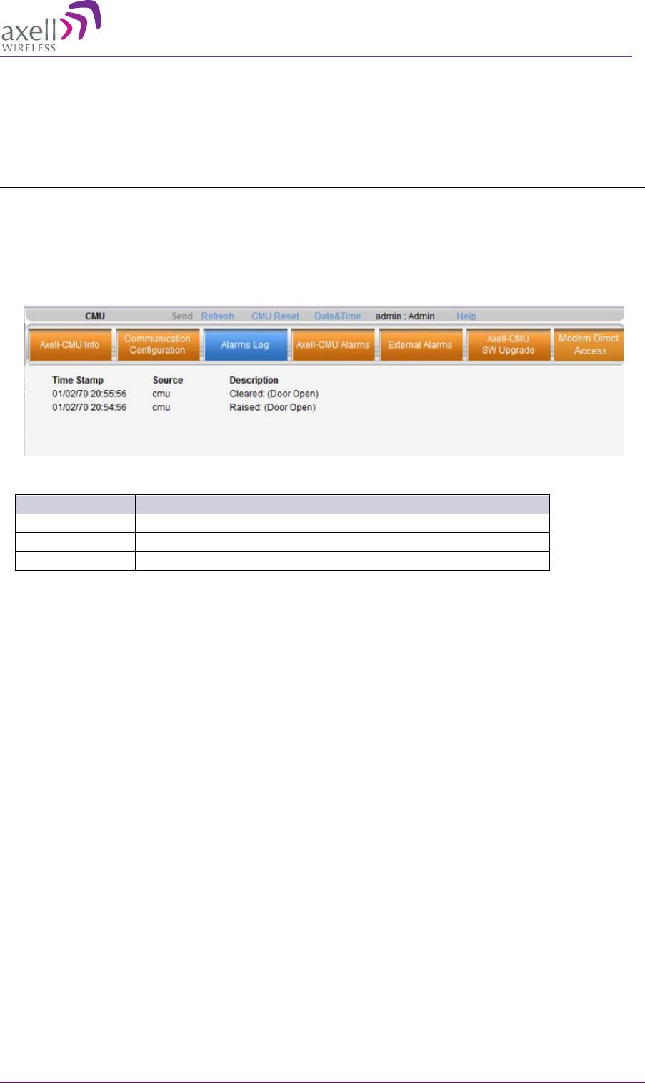
AXELL DIGIMINI- AMERICAS REPEATER
PRODUCT DESCRIPTION AND USER’S MANUAL
© Axell Wireless Ltd DIGImini Americas User Manual Rev 3.5 77
6.9.2 Viewing the Alarms Log
The Alarms Logs screen lists the alarms (events) that have occurred. The CMU maintains log files
listing every alarm triggered and in the Repeater. This screen provides an analysis tool to get
information of any event that has occurred, its originator, when, if they return, and their type.
NOTE: Set the clock in order to synchronize the events time of occurrence (see section
6.6.2).
To view the CMU log screen:
1. Open and login to the Web application.
2. From the Tree Pane, select CMU.
3. Click Alarms Logs. CMU displays the Alarms Log Table.
Item
Description
Time Stamp
The date and time the alarm was created
Source
ID of Network Element
Description
Description of event that caused the alarm
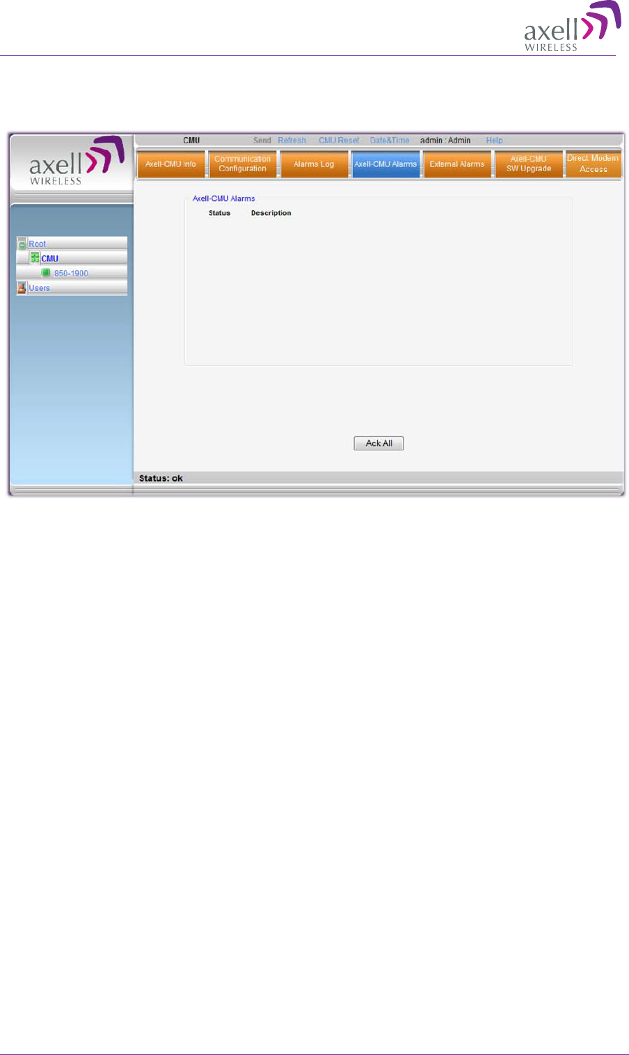
AXELL DIGIMINI- AMERICAS REPEATER
PRODUCT DESCRIPTION AND USER’S MANUAL
78 DIGImini Americas User Manual Rev 3.5 © Axell Wireless Ltd
6.9.3 Viewing External Alarms Log
This tab is used to view the status of the connected external alarms.
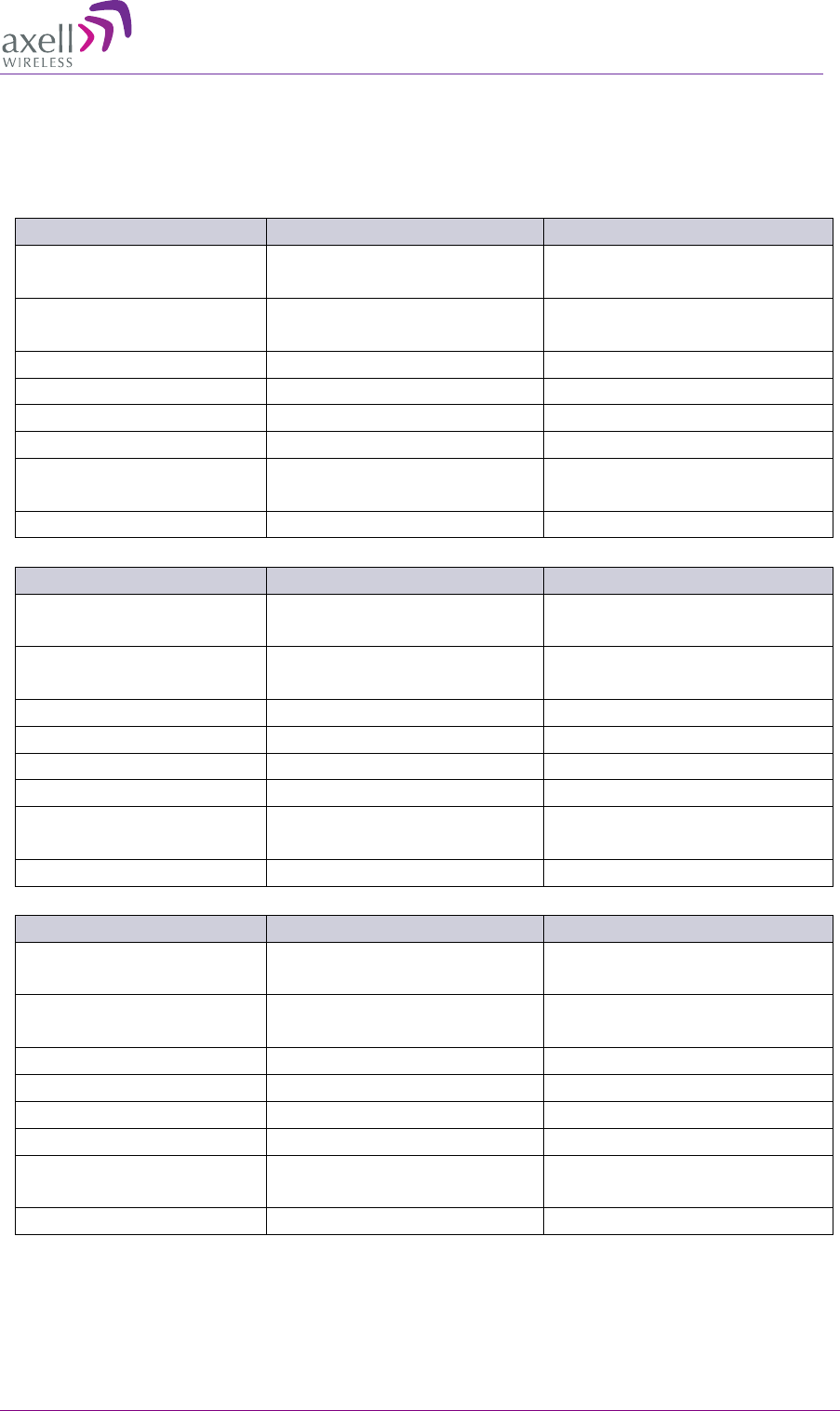
AXELL DIGIMINI- AMERICAS REPEATER
PRODUCT DESCRIPTION AND USER’S MANUAL
© Axell Wireless Ltd DIGImini Americas User Manual Rev 3.5 79
Appendix A: Specifications (@+25°C)
This paragraph provides the electrical, mechanical and environmental specifications of the DIGImini
Americas Repeater.
700 MHz
Downlink
Uplink
Frequency Range
Lower Band: 728-746 MHz
Upper Band: 746 -757 MHz
Lower Band: 698-716 MHz
Upper Band: 776 -787 MHz
No. of Filters per Band*
Up to 6
Up to 6
Passband Max.Gain
73 dB
73 dB
Passband Ripple
±2.5 dB
±2.5 dB
Gain Attenuation Range
0 to 25 dB (in 1 dB steps)
0 to 25 dB (in 1 dB steps)
Composite Output Power
21dBm**
21dBm**
Noise Figure@ Maximum
Gain (typical)
6 dB
6 dB
Propagation Delay
6 µsec
6 µsec
1700 MHz
Downlink
Uplink
Frequency Range
2110 – 2155 MHz
1710-1755 MHz
No. of Filters per Band*
Up to 6
Up to 6
Passband Max.Gain
73 dB
73 dB
Passband Ripple
±2.5 dB
±2.5 dB
Gain Attenuation Range
0 to 25 dB (in 1 dB steps)
0 to 25 dB (in 1 dB steps)
Composite Output Power
20dBm**
20dBm**
Noise Figure @ Maximum
Gain (typical)
6 dB
6 dB
Propagation Delay
6 µsec
6 µsec
850 MHz
Downlink
Uplink
Frequency Range
869 – 894 MHz
824-849 MHz
No. of Filters per Band*
Up to 6
Up to 6
Passband Max.Gain
73 dB
73 dB
Passband Ripple
±2.5 dB
±2.5 dB
Gain Attenuation Range
0 to 25 dB (in 1 dB steps)
0 to 25 dB (in 1 dB steps)
Composite Output Power
21dBm**
21dBm**
Noise Figure@ Maximum
Gain (typical)
6 dB
6 dB
Propagation Delay
6 µsec
6 µsec
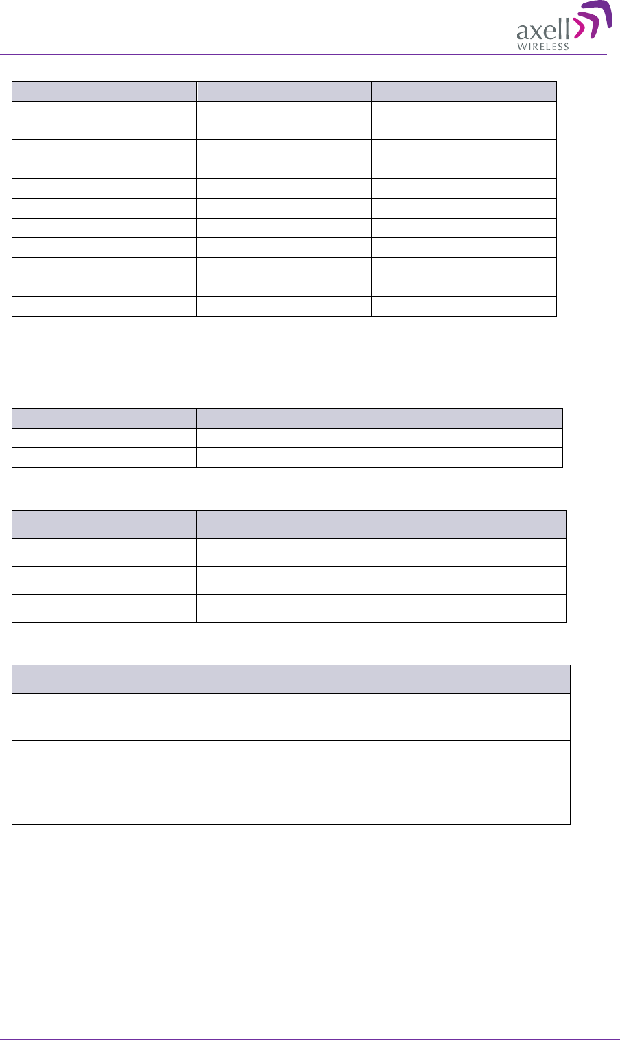
AXELL DIGIMINI- AMERICAS REPEATER
PRODUCT DESCRIPTION AND USER’S MANUAL
80 DIGImini Americas User Manual Rev 3.5 © Axell Wireless Ltd
1900 MHz
Downlink
Uplink
Frequency Range
1930-1990 MHz
1850 – 1910 MHz
No. of Filters per Band*
Up to 6
Up to 6
Passband Max.Gain
73 dB
73 dB
Passband Ripple
±2.5 dB
±2.5 dB
Gain Attenuation Range
0 to 25 dB (in 1 dB steps)
0 to 25 dB (in 1 dB steps)
Composite Output Power
20dBm**
20dBm**
Noise Figure@ Maximum
Gain (typical)
6 dB
6 dB
Propagation Delay
6 µsec
6 µsec
(*) Supports every BW option 200KHz-25MHz by setting the Stop-Start frequency. Total numbers of filters is 6 per dual-
band. See section 5.2.5 for details.
(**) 3.5dB less in tri/quad band configurations due to combining loss.
Electrical
Parameter
Value
Power Supply
100 - 240 VAC, 150W (typical)
Power Consumption
< 70Watt for dual-band, < 45Watt for single band
Mechanical Specifications
Parameter Value
Dimensions (b x h x d) 299 x 305 x 77 mm (11.7 x 12 x 3.03 inch)
Installation Wall Mount
Weight 8.9 lbs for dual-band
Environmental Specifications
Condition Value
Operating Temperature
Range 0 °C to +50 °C (32° to 122° F)
Humidity 85%, ETS 300 019-1-3 Class 3.1
Ingress Protection IP41
MTBF, Complete System >70,000 hrs.
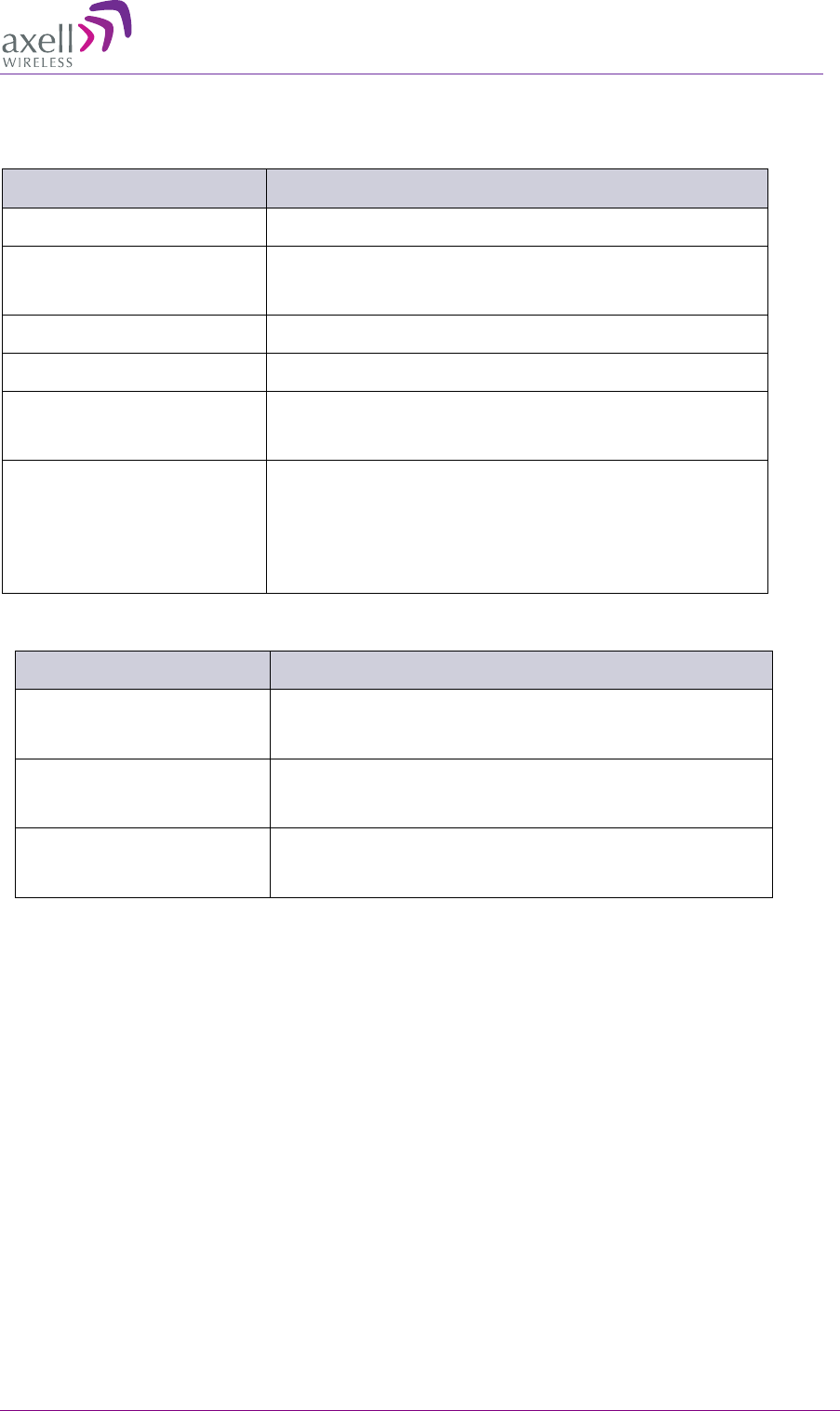
AXELL DIGIMINI- AMERICAS REPEATER
PRODUCT DESCRIPTION AND USER’S MANUAL
© Axell Wireless Ltd DIGImini Americas User Manual Rev 3.5 81
Connectors
Connector Type
RF Connectors: Base/Mobile N-Type, Female
AC Power Standard AC socket to AC/DC converter;
DC socket to Repeater
Communications RJ45
Modem Connection External modem in DMCU
Coupling SMA Connectors
(-20 dB): Base/Mobile
SMA female
Alarm inputs –
in modem
plug (2 external devices) Dry Contacts – 6 pins:
Normally Closed (NC);
Common;
Normally Open (NO)
Standard Compliance
Model Compliance
D-MINI-2108-2019 FCC: NEO-DMINI21082019
IC: 8749A-DM819
D-MINI-2107U-2017 FCC: NEO-DMINI2107U2017
IC:8749A-DM7U17
D-MINI-2107L-2017 FCC: NEO-DMINI2107L2017
IC:8749A-DM7L17