Axell Wireless MBF23082319 MBF2001A Dual Band Optical Repeater User Manual Manual
Axell Wireless MBF2001A Dual Band Optical Repeater Manual
UserManual.wiki
>
Axell Wireless
>
MBF23082319 User Manual
>
Manual
Contents
1.
Manual
2.
OMUII Datasheet
Manual
Navigation menu
Upload a User Manual
Namespaces
Wiki Guide
HTML
PDF
Info
Views
User Manual
Discussion / Help
Navigation


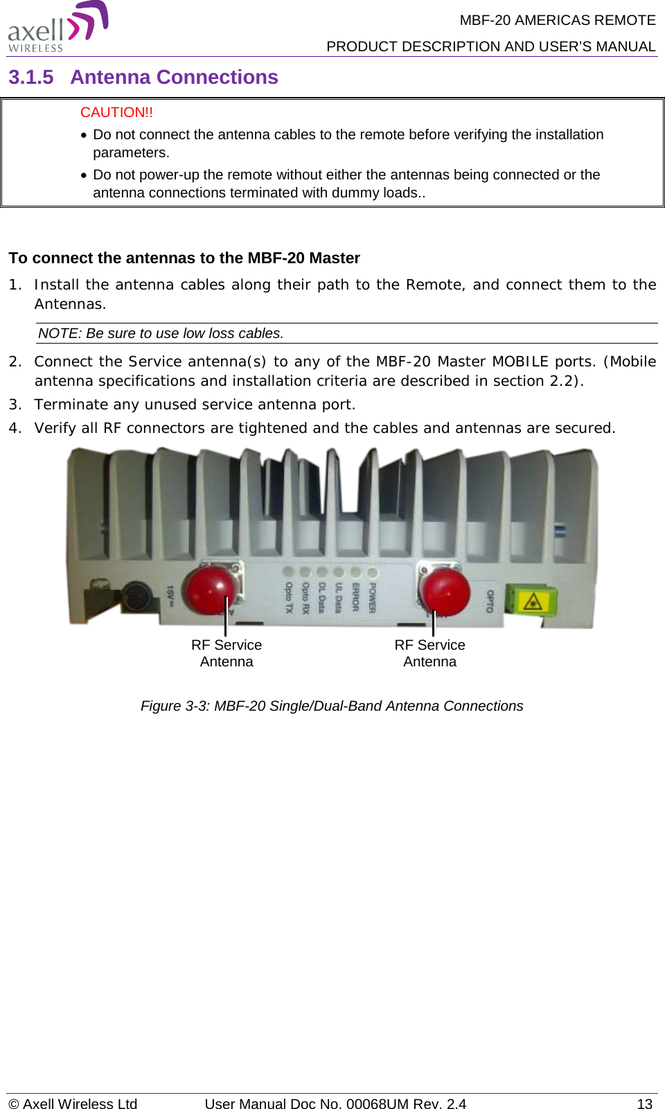
![MBF-20 AMERICAS REMOTE PRODUCT DESCRIPTION AND USER’S MANUAL © Axell Wireless Ltd User Manual Doc No. 00068UM Rev. 2.4 7 Specifications: • One or a combination of the following antennas can be used: Ceiling Mount Patch antenna, Wall Mount Patch antenna, Corner Reflector. • Choose an antenna with high side lobe attenuation which enables maximum isolation from other service/ mobile antennas. • Net gain [Gain Antenna – Cable loss] must not exceed 13 dBi • Antennas with gain < 13 dBi can be connected directly to the MBF-20 ports. • Higher gain antennas may be connected to the MBF-20 ports along with adequate cable and splitting losses 2.2.3 Service Antenna Installation Criteria Determine the antenna installation configuration, according to the transmission requirements and the installation site conditions. Installation requirements: • An indoor antenna should be installed at a convenient location. It should be free of metallic obstruction. • Install the Service Antenna at the designated height and tune it roughly toward the Service coverage area. • Installation of this antenna must provide a minimum separation distance of 35cm from any personnel within the area. 2.3 Service Antenna Requirements (French) Cette section fournit des informations sur les spécifications du donneur et des antennes de services adaptés pour fonctionner avec ce répéteur, sur les conditions d'installation des antennes et sur le site d'installation de répéteur et exigences de câblage. ATTENTION!! • L'installateur est tenu pour responsable de la mise en œuvre des règles nécessaires au déploiement. • Les bonnes pratiques d'ingénierie doit être utilisée pour éviter les interférences. • Puissance de sortie doit être réduite pour résoudre tous les problèmes d'interférence de l'IMD. 2.3.1 Antenne Informations Requises Les exigences d'antenne suivants, les spécifications et considérations du site doivent être remplies: • Type de zone de service et la taille • Type et les caractéristiques de l'antenne • Hauteur • La longueur et le type de câble coaxial requis pour relier l'antenne au répéteur et l'atténuation.](https://usermanual.wiki/Axell-Wireless/MBF23082319.Manual/User-Guide-2292591-Page-15.png)
![MBF-20 AMERICAS REMOTE PRODUCT DESCRIPTION AND USER’S MANUAL 8 User Manual Doc No. 00068UM Rev. 2.4 © Axell Wireless Ltd 2.3.2 FCC et IC conformité de l'installation intérieure L'antenne de service est installé à l'intérieur, où le type d'antenne dépend de l'application.: • Un ou une combinaison des antennes suivantes peuvent être utilisées: Antenne Patch pour montage au plafond, antenne Patch pour montage mural, Réflecteur en Coin. • Choisissez une antenne à haute côté atténuation du lobe qui permet une isolation maximum des autres services / antennes mobiles. • Gain net [Gain Antenna - la perte de câble] ne doit pas dépasser 13 dBi • Les antennes à gain <13 dBi peut être connectée directement aux ports MBF-20. • Antennes à gain plus élevées peuvent être connectés aux ports MBF-20 avec des pertes de câble et de division adéquates. 2.3.3 Critères d'installation de l'antenne d'installation d'intérieur Déterminer la configuration de l'installation de l'antenne, selon les exigences de transmission et les conditions du site d'installation. Exigences d'installation: • Une antenne intérieure doit être installée à un endroit pratique. Il doit être libre de tout obstacle métallique. • Installez l'antenne de service à la hauteur désignée et l'accorder à peu près vers la zone de couverture du service. • L'installation de cette antenne doit fournir une distance minimale de séparation de 35 cm de tout le personnel dans la région](https://usermanual.wiki/Axell-Wireless/MBF23082319.Manual/User-Guide-2292591-Page-16.png)