Axell Wireless MBF23082319 MBF2001A Dual Band Optical Repeater User Manual OMUII Datasheet
Axell Wireless MBF2001A Dual Band Optical Repeater OMUII Datasheet
Contents
- 1. Manual
- 2. OMUII Datasheet
OMUII Datasheet
Product Specification Sheet
©Axell Wireless | www.axellwireless.com | info@axellwireless.com | Version: 3.5 | E & O.E. All specifications are subject to change without prior notice.
1
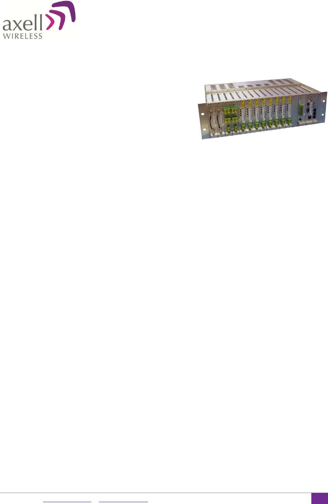
OMU II
Optical Master Unit
Key features:
Supports Cellular 2G, 3G, 4G services up to 2700MHz & public
safety services FM/VHF/UHF/LMR on the same enclosure
Single enclosure to support high power (MBF-40) and low
power (MBF-20) remote units
MIMO support
Web based remote management via wireless modem
Flexible configuration to support up to 8 sectors via single chassis
Simple integration to AEM or any other 3rd party NOC via SNMP traps
The OMU II is used to convert signals
from RF to light when fibre-fed
repeaters are used at the remote
end of the optical link. The OMU II is
a headend system that can be
connected directly to a base station
or off-air device such as a digital
repeater or bi-directional amplifier.
For larger venues with multiple
services and multiple bands, a Point
Of Interface (POI) unit may be
required to condition Uplink and
Downlink RF signals between the
BTS/Off-air Repeater and the OMU.
In the downlink direction, the OMU
picks up the signal from the BTS,
converts it into an optical signal and
transfers it over a fibre optical cable
to the repeater. In the uplink
direction, the OMU receives the
signal from the remote repeater via
the fibre optical cable, converts it to
a RF signal and sends it back to the
base station.
Architecture
Each OMU II has a dedicated control
card, alarm and battery backup card,
rack communication board (RCB),
optional modem card and 2 AC/DC
power supplies on the back of the
chassis. It has 12 slots in the front to
support the Opto Module cards and
Signal Conditioning Card- Optical
Splitter Module (OSM). The OSM
cards include a 1:4 optical splitter
hence it can support up to 4 MBF-20
units from a single OSM.
The OMU II can support up to 8 of
our standard high powered MBF-40
or 24 low powered MBF-20
remotes. For the maximum number
on MBF-20 remote units, 6 Opto
Modules and 6 OSM are used which
may be configured according to the
number of sectors used in the
project – up to 6 sectors in this
configuration. If only MBF-40 units
are required, up to 8 Opto Module
cards are used (no OSM cards) which
may be configured according to the
number of sectors used in the
project – up to 8 sectors in this
configuration. You can mix and
match between the MBF-40 and MBF
20 remote units. Please refer to the
2nd page for all the available
options.
Automatic Optical Gain Setting
The fibre optic system Axell Wireless
has designed puts a clear focus on
user friendliness and ease of
installation and commissioning.
Through an automatic optical gain
setting, the commissioning is easily
performed, thus reducing the time it
takes to put the equipment in
service. This also means that the
training is significantly simplified and
the need for installation effort is
decreased.
Remote Supervision
Only one modem is needed to
communicate with an OMU II and its
fibre fed repeaters. The modem
types available are GSM, UMTS,
CDMA 1x, PSTN, and TCP/IP. The
modem is found inside the OMU II
and communication with the fibre-
fed remote units is transparently
handled via the fibre that connects
them. The system can be monitored
and controlled via the Axell Wireless’
network management software tool
called AEM. AEM communicates with
each fibre remote unit via the OMU
over the same single mode fibre
strand that carries the RF signals.
Both data communications and the
RF signals are managed over the
same fibre link which results in a very
reliable supervision of the radio link.
The OMU Mark II supports: public
safety services (VHF, UHF, TETRA,
SMR 700/800/900), cellular bands for
EMEA and APAC (800 / 900 / 1800 /
2100 / 2600) and LTE700, 850, PCS
and AWS for Americas and is always
used in combination with one or
several fibre fed repeaters.

©Axell Wireless | www.axellwireless.com | info@axellwireless.com | Version: 3.5| E & O.E. All specifications are subject to change without prior notice.
2
Technical specifications
RF Parameters
Frequency bands
68-500 / 380-2200 / 700-2700 MHz
Gain flatness
typical 2 dB (p-p)
Nominal RF input power
+10 dBm composite power
Absolute maximum RF input power
+23 dBm composite power
Number of optical modules
1-24 (depends on low/high power configuration)
MBF-40 (high power)
MBF-20 (low power)
The table to the left lists the
various high (MBF-40) and
low (MBF-20) power remote
unit configurations and how it
affects the total number of
links supported.
For example: if the OMU II
supports two high power fibre
remotes, then the available
low power links = 20
8
0
7
4
6
8
5
12
4
16
3
16
2
20
1
20
0
24
Laser class
Class 1
Optical module electrical specification
Optical wavelength Downlink (± 10 nm)
1310
Optical wavelength Uplink (± 3 nm)
1510 or 1530 or 1550 or 1570 or 1590
Maximum optical input power
+5 dBm
Output power (Tx) max
+7 dBm
Automatic fibre optic loss compensation
Yes
Optical Splitter Module (OSM) electrical specification
Optical splitter (OSM) input power
+5 ± 1 dBm
Insertion loss
7dBo
Power requirements
Power requirements
230/115 VAC, 50/60 Hz,-48 VDC
Power consumption
Typical 50 W (fully equipped)
External electrical interfaces
Local maintenance terminal
Ethernet, USB, RS232
RF ports
N-type Connector Female for 1-2 sectors. SMA connectors for 8 sectors
Optical ports
SC/APC
AC/DC mains input
AC: IEC Connector with main lead supplied according to the region. DC: flying
leads for connection to terminal block
External alarms
Via Front panel
Modem connector
RJ45 for wireless modem , RJ11 for PSTN modem
Modem antenna connector
(Wireless modem)
SMA
Ethernet connector
RJ45
Mechanical specifications
Dimensions (W x H x D)
17.5 x 5.2 x 11.4 in (444 x 132.5 x 291 mm) 19” rack
Weight
33 lbs (15 kg) (fully equipped)
IP rating
IP20
Environmental
Operating temperature
+41 to 113° F (+5 to +45°C)
About Axell Wireless
Axell Wireless is one of the top global providers of wireless coverage solutions and the market leader in the
provision of solutions for the public safety market worldwide. Our equipment has been deployed in some of the
most technologically challenging environments in the world, providing coverage for tunnels, metros, buildings,
stadiums and transportation systems all over the world. With its headquarters in the UK, Axell Wireless has been
operating for over 40 years and has an international footprint. A proven track record combined with a reputation
for providing innovative and high-quality products has made Axell Wireless a truly global player in the wireless
coverage industry.