Axell Wireless MBF4050 MBF4050, (MBF4317-4319 115V Dual Band) Fibre Optic Repeater User Manual
Axell Wireless MBF4050, (MBF4317-4319 115V Dual Band) Fibre Optic Repeater
User Manual
AXELL MBF-40 AMERICAS REPEATERS
PRODUCT DESCRIPTION AND USER’S MANUAL
Axell MBF-40 Multi Band Repeater-Americas
PRODUCT DESCRIPTION AND USER’S MANUAL
Doc No. 00071UM Rev. 3.4
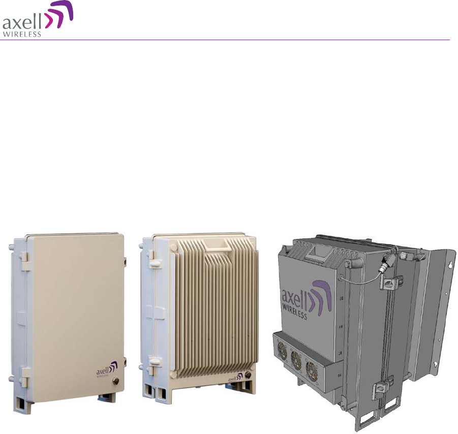
Single/Dual-Band
Repeater Tri/Quad-Band
Repeater Quad-Band with Fan Hood
Repeater

AXELL MBF-40 AMERICAS REPEATERS
PRODUCT DESCRIPTION AND USER’S MANUAL
II Doc. No. 00071UM Rev. 3.4 © Axell Wireless Ltd
THIS DOCUMENT IS VALID FOR THE FOLLOWING MBF-40 MODELS:
MBF-40 US Repeaters
Dual Band MBF-3708-3719; MBF-3707-3917; MBF-3707-3719;
MBF-3707-4317; MBF-4317-3919; MBF-4317-4319;
Tri-Band MBF-3708-3917-3719; MBF-3707-3708-3917;
MBF-3707-3708-3719;
Quad-Band MBF-3707-3708-3917-3719;
MIMO MBF-3917-3917M-3719
MBF-40 Canada Repeaters
Single Band MBF-4307-AO; MBF-3707S-AO;
Dual Band MBF-3708S-3709S-M; MBF-4317-4326-M;
Quad-Band MBF-4308-4317-4319-4326-M-F;
MBF-3707-3708-3917-3719 GB 115V
MIMO MBF-4307-4307-M-AO
AXELL MBF-40 AMERICAS REPEATERS
PRODUCT DESCRIPTION AND USER’S MANUAL
© Axell Wireless Ltd Doc. No. 00071UM Rev. 3.4 III
Copyright © 2015 Axell Wireless Ltd
All rights reserved.
No part of this document may be copied, distributed, transmitted, transcribed, stored in a retrieval system, or
translated into any human or computer language without the prior written permission of Axell Wireless Ltd.
The manufacturer has made every effort to ensure that the instructions contained in this document are
adequate and free of errors and omissions. The manufacturer will, if necessary, explain issues which may not
be covered by this document. The manufacturer's liability for any errors in the document is limited to the
correction of errors and the aforementioned advisory services.
This document has been prepared to be used by professional and properly trained personnel, and the
customer assumes full responsibility when using them. The manufacturer welcomes customer comments as
part of the process of continual development and improvement of the documentation in the best way possible
from the user's viewpoint. Please submit your comments to the nearest Axell Wireless sales representative.
Contact Information
Headquarters Axell Wireless
Aerial House
Asheridge Road
Chesham
Buckinghamshire HP5 2QD
United Kingdom
Tel: +44 1494 777000
Fax: +44 1494 777002
Commercial inquiries info@axellwireless.com
Web site www.axellwireless.com
Support issues support@axellwireless.com
Technical Support Line, English
speaking +44 1494 777 747
Contact information for Axell Wireless offices in other countries can be found on our web
site, www.axellwireless.com

AXELL MBF-40 AMERICAS REPEATERS
PRODUCT DESCRIPTION AND USER’S MANUAL
IV Doc. No. 00071UM Rev. 3.4 © Axell Wireless Ltd
About This Manual
This Product Manual provides the following information:
• Description of the MBF-40 Americas Repeaters
• Procedures for setup, configuration and checking the proper operation of the MBF-40
• Maintenance and troubleshooting procedures
Intended Audience
This Product Manual is intended for experienced technicians and engineers. It is
assumed that the customers installing, operating, and maintaining Axell Wireless
Remotes are familiar with the basic functionality of Remote repeaters.
Notice
Confidential - Authorized Customer Use
This document may be used in its complete form only and is solely for the use of Axell
Wireless employees and authorized Axell Wireless channels or customers. The material
herein is proprietary to Axell Wireless. Any unauthorized reproduction, use or disclosure
of any part thereof is strictly prohibited.
All trademarks and registered trademarks are the property of their respective owners.
Disclaimer of Liability
Contents herein are current as of the date of publication. Axell Wireless reserves the
right to change the contents without prior notice. The information furnished by Axell
Wireless in this document is believed to be accurate and reliable. However, Axell
Wireless assumes no responsibility for its use. In no event shall Axell Wireless be liable
for any damage resulting from loss of data, loss of use, or loss of profits and Axell
Wireless further disclaims any and all liability for indirect, incidental, special,
consequential or other similes damages. This disclaimer of liability applies to all
products, publications and services during and after the warranty period.
Guarantees
• All antennas must be installed with lightning protection. Damage to power
modules, as a result of lightning are not covered by the warranty.
• Antennas must be connected before switching on AC or DC power. Switching
power on prior to the connection of antenna cables is regarded as faulty installation
procedure and therefore not covered by the Axell Wireless warranty.
Exclusive Remedies
The remedies provided herein are the Buyer’s sole and exclusive remedies. Axell
Wireless shall not be viable for any direct, incidental, or consequential damages,
whether based on contract, tort, or any legal theory.

AXELL MBF-40 AMERICAS REPEATERS
PRODUCT DESCRIPTION AND USER’S MANUAL
© Axell Wireless Ltd Doc. No. 00071UM Rev. 3.4 V
Compliance with FCC
FCC Part 20 Warning Statement
WARNING: This is NOT a CONSUMER device. It
is designed for installation by
FCC LICENCEES and QUALIFIED INSTALLERS. You must have an FCC
LICENCE or express consent of an FCC Licensee to operate this device.
Unauthorized use may result in significant forfeiture penalties, including
penalties in excess of $100,000 for each continuing violation.
If not installed and used in accordance with the instructions, this equipment generates,
uses and can radiate radio frequency energy. However, there is no guarantee that
interference will not occur in a particular installation. If this equipment does cause
harmful interference to RF reception, which can be determined by turning the equipment
off and on, the user is encouraged to try to correct the interference by one or more of
the following measures:
• Increase the separation between the equipment and receiver.
• Connect the equipment into an outlet on a circuit different from that to which the
receiver is connected.
Unauthorized Changes to Equipment
Changes or Modifications not expressly approved by the manufacturer responsible for
compliance could void the user’s authority to operate the equipment.
FCC RF Exposure Limits
This unit complies with FCC RF exposure limits for an uncontrolled environment. This
equipment must be installed and operated with a minimum distance of 110 cm. between
the radiator and any person’s body.
Antenna Installation
Installation of an antenna must comply with the FCC RF exposure requirements. The
antenna used for this booster must be mounted on outdoor or indoor permanent
structures.

AXELL MBF-40 AMERICAS REPEATERS
PRODUCT DESCRIPTION AND USER’S MANUAL
VI Doc. No. 00071UM Rev. 3.4 © Axell Wireless Ltd
Compliance with IC
Under Industry Canada regulations, this radio transmitter may only operate using an
antenna of a type and maximum (or lesser) gain approved for the transmitter by
Industry Canada.
To reduce potential radio interference to other users, the antenna type and its gain
should be so chosen that the equivalent isotropically radiated power (e.i.r.p.) is not
more than that necessary for successful communication.
The Manufacturer's rated output power of this equipment is for single carrier operation.
For situations when multiple carrier signals are present, the rating would have to be
reduced by 3.5dB, especially where the output signal is re-radiated and can cause
interference to adjacent band users. This power reduction is to be by means of input
power or gain reduction and not by an attenuator at the output of the device.
Conformément à la réglementation d'Industrie Canada, le présent émetteur radio peut
fonctionner avec une antenne d'un type et d'un gain maximal (ou inférieur) approuvé
pour l'émetteur par Industrie Canada.
Dans le but de réduire les risques de brouillage radioélectrique à l'intention des autres
utilisateurs, il faut choisir le type d'antenne et son gain de sorte que la puissance
isotrope rayonnée équivalente (p.i.r.e.) ne dépasse pas l'intensité nécessaire à
l'établissement d'une communication satisfaisante.
La puissance de sortie nominale indiquée par le fabricant pour cet appareil concerne son
fonctionnement avec porteuse unique. Pour des appareils avec porteuses multiples, on
doit réduire la valeur nominale de 3.5dB, surtout si le signal de sortie est retransmis et
qu'il peut causer du brouillage aux utilisateurs de bandes adjacentes. Une telle réduction
doit porter sur la puissance d'entrée ou sur le gain, et ne doit pas se faire au moyen
d'un atténuateur raccordé à la sortie du dispositif.
AXELL MBF-40 AMERICAS REPEATERS
PRODUCT DESCRIPTION AND USER’S MANUAL
© Axell Wireless Ltd Doc. No. 00071UM Rev. 3.4 VII
General Safety Warnings Concerning Use of
System
Caution labels!
Throughout this manual, there are "Caution" warnings.
"Caution" calls attention to a procedure or practice, which, if
ignored, may result in injury or damage to
the system,
system component or even the user. Do not perform any
procedure preceded by a "Caution" until the described
conditions are fully understood and met.
Electrical Shock
Danger:
To prevent electrical shock when installing or
modifying the system power wiring, disconnect the wiring at
the power source before working with un insulated wires or
terminals.
Caution: Safety to
personnel
Before installing or replacing any of the equipment, the entire
manual should be read and understood.
The user needs to supply the appropriate AC or DC power to
the repeater. Incorrect power settings can damage the
repeater and may cause injury to the user.
Please be aware that the equipment may, during certain
conditions become very warm and can cause minor injuries if
handled without any protection, such as gloves.
Caution: RF Exposure
RF radiation, arising from transmitter outputs connected to
AWL’s equipment, must be considered a safety hazard.
This condition might only occur in the event of cable
disconnection, or because a ‘spare’ output has been left un-
terminated. Either of these conditions would impair the
system’s efficiency. No investigation should be carried out
until all RF power sources have been removed. This would
always be a wise precaution, despite the severe mismatch
between the impedance of an N type connector at 50 ohm,
and that of free space at 377 ohm, which would severely
compromise the efficient radiation of RF power. Radio
frequency burns could also be a hazard, if any RF power
carrying components were to be carelessly touched!
Antenna positions should be chosen to comply with
requirements (both local & statutory) regarding exposure of
personnel to RF radiation. When connected to an antenna, the
unit is capable of producing RF fi
eld strengths, which may
exceed guideline safe values especially if used with antennas
having appreciable gain. In this regard the use of directional
antennas with backscreens and a strict site rule that
personnel must remain behind the screen while the RF power
is on, is strongly recommended.
Where the equipment is used near power lines or in
association with temporary masts not having lightning
protection, the use of a safety earth connected to the case-
earthing bolt is strongly advised.
AXELL MBF-40 AMERICAS REPEATERS
PRODUCT DESCRIPTION AND USER’S MANUAL
VIII Doc. No. 00071UM Rev. 3.4 © Axell Wireless Ltd
Caution: Safety to
equipment
When installing, replacing or using this product, observe all
safety precautions during handling and operation. Failure to
comply with the following general safety precautions and with
specific precautions described elsewhere i
n this manual
violates the safety standards of the design, manufacture, and
intended use of this product.
Changes or modifications not expressly approved by the party
responsible for compliance could void the user’s authority to
operate the equipment.
Axell Wireless assumes no liability for the customer's failure
to comply with these precautions. This entire manual should
be read and understood before operating or maintaining the
repeater.
Warning: Restricted
Access Location
Access to the Axell unit
installation location is restricted to
SERVICE PERSONNEL and to USERS who have been
instructed on the restrictions and the required precautions to
be taken.
Attention:
Electrostatic
Sensitivity
Observe electrostatic precautionary procedures.
ESD = Electrostatic Discharge Sensitive Device.
Static electricity can be conducted to the semiconductor chip
from the centre pin of the RF input connector, and through
the AC connector pins. When unpacking and otherwise
handling the repeater, follow ESD precautionary procedures
including use of grounded wrist straps, grounded workbench
surfaces, and grounded floor mats.
Caution: Class 1
Laser
The repeaters described in this manual are equipped with
class 1 lasers, as per definition in EN 60825-1
Caution - Un-terminated optical receptacles may emit laser
radiation. Exercise caution as follows:
• Do not stare into beam or view with optical instruments.
Optical transmitters in the Fiber optic converter can send
out high energy invisible laser radiation. There is a risk for
permanent damage to the eye.
• Always use protective cover on all cables and connectors
which are not connected.
• Never look directly into a Fiber cable or a connector.
• Consider that a Fiber can carry transmission in both
directions.
• During handling of laser cables or connections, ensure
that the source is switched off.
• Regard all open connectors with respect and direct them
in a safe direction and never towards a reflecting surface.
Reflected laser radiation should be regarded as equally
hazardous as direct radiation.

AXELL MBF-40 AMERICAS REPEATERS
PRODUCT DESCRIPTION AND USER’S MANUAL
© Axell Wireless Ltd Doc. No. 00071UM Rev. 3.4 IX
Table of Contents
Unauthorized Changes to Equipment ................................................................................................V
FCC RF Exposure Limits .......................................................................................................................V
Antenna Installation ...............................................................................................................................V
1 Introduction ................................................................................................................................ 1
1.1 Features and Capabilities ............................................................................................................. 2
1.2 ALC ..................................................................................................................................................... 3
1.3 MIMO Topology ............................................................................................................................... 3
1.4 Five-Band Configuration ............................................................................................................... 4
1.5 Operating Temperature ................................................................................................................. 5
1.6 MBF-40 Management Web GUI .................................................................................................... 5
1.7 MBF-40 Basic Interfaces ............................................................................................................... 5
1.7.1 Securing the Unit ................................................................................................................ 6
1.7.2 External Interfaces .............................................................................................................. 7
1.7.3 Internal Interfaces ............................................................................................................... 8
2 Installation Requirements .................................................................................................... 11
2.1 MBF-40 Installation requirements ............................................................................................ 11
2.1.1 Safety Guidelines .............................................................................................................. 11
2.1.2 Criteria for Repeater Installation Location ..................................................................... 11
2.1.3 RF Cable Installation Guidelines .................................................................................... 12
2.1.4 F/O Cable Installation Guidelines ................................................................................... 12
2.2 Service Antenna Requirements (English) .............................................................................. 13
2.2.1 Required Antenna Information ........................................................................................ 13
2.2.2 Recommended Antennas ................................................................................................ 13
2.2.3 Recommended Splitters and Couplers .......................................................................... 14
2.3 Service Antenna Requirements (French) ............................................................................... 14
2.3.1 Antenne Informations Requises...................................................................................... 14
2.3.2 FCC et IC conformité de l'installation intérieure ........................................................... 15
2.3.3 Critères d'installation de l'antenne d'installation d'intérieur ........................................ 15
2.3.4 Indoor Installations Service/Mobile Antenna Requirements ....................................... 15
2.3.5 Outdoor Installations......................................................................................................... 15
3 Repeater Installation .............................................................................................................. 16
3.1 Location Criteria ........................................................................................................................... 16
3.2 Standard Repeater Installation .................................................................................................. 17
3.2.1 Unpacking .......................................................................................................................... 17
3.2.2 Parts List ............................................................................................................................ 17
3.2.3 Bracket Assembly ............................................................................................................. 18
3.2.4 Wall Marking and Drilling ................................................................................................. 19
3.2.5 Mount the Repeater .......................................................................................................... 22
3.3 Repeater with Fan Hood Installation ....................................................................................... 23
3.3.1 Dimensions ........................................................................................................................ 24
3.3.2 Parts List ............................................................................................................................ 25
3.3.3 Fan Hood and Bracket Assembly ................................................................................... 26
3.4 Five-Band System Installation................................................................................................... 30
3.4.1 Required Items for a Master Slave System .................................................................. 31
3.4.2 Mounting the Master and Slave Units ............................................................................ 31
3.4.3 Connecting Master and Slave Units ............................................................................... 32
3.4.4 Master/Slave Connections for External Alarms ............................................................ 34

AXELL MBF -40 AMERICAS REPEATERS
PRODUCT DESCRIPTION AND USER’S MANUAL
X Doc. No. 00071UM Rev. 3.4 © Axell Wireless Ltd
3.5 Grounding ....................................................................................................................................... 35
3.6 Ensure Good EMV Protection .................................................................................................... 36
3.7 Fiber Optic Connection ............................................................................................................... 38
3.8 External Alarm and Relay Connections .................................................................................. 41
3.8.1 External Alarm ................................................................................................................... 41
3.8.2 Relay ................................................................................................................................... 41
3.9 Power and Backup Battery ......................................................................................................... 42
3.9.1 Dual Power Supply Models ............................................................................................. 42
3.9.2 Circuit Breaker ................................................................................................................... 42
3.9.3 Connecting the Power Source ........................................................................................ 43
3.9.4 115 VAC Power Source ................................................................................................... 43
3.9.5 -48V Power Source Connection...................................................................................... 44
3.9.6 Backup Battery .................................................................................................................. 45
3.10 Power ON ........................................................................................................................................ 46
3.10.1 Switching Power ON ......................................................................................................... 46
3.10.2 Verifying LEDs ................................................................................................................... 46
3.11 Closing and Securing the Repeater ......................................................................................... 46
4 Opening a Session and Navigating GUI ........................................................................... 47
4.1 Opening a Direct Web Session .................................................................................................. 47
4.1.1 Connecting Locally ............................................................................................................ 47
4.1.2 Remote Connection and Login ....................................................................................... 48
4.2 Open a Session to the MBF-40 via the OMU II ....................................................................... 49
4.3 Navigating the Web Interface ..................................................................................................... 50
4.3.1 Management Options Buttons ......................................................................................... 51
4.3.2 Home Screen Overview ................................................................................................... 52
4.3.3 Configuration Screen Overview ...................................................................................... 53
4.3.4 Five Service System GUI ................................................................................................. 54
5 MBF-40 Commissioning ........................................................................................................ 56
5.1 MBF-40 Optical Loss Adjustment (OLA) ................................................................................. 56
5.2 RF Balancing .................................................................................................................................. 58
5.2.1 Manual RF Balancing ....................................................................................................... 58
5.2.2 Automatic MBF-40 RF Balancing ................................................................................... 60
5.3 Integration into the AEM ............................................................................................................. 61
5.4 What Next? ..................................................................................................................................... 61
6 MBF-40 Full GUI Description ............................................................................................... 62
6.1 Configuring General Parameters .............................................................................................. 62
6.1.1 Site Information – MBF-40 Identification ....................................................................... 62
6.1.2 Date & Time ....................................................................................................................... 63
6.1.3 Configure External Alarms ............................................................................................... 63
6.1.4 IP Address .......................................................................................................................... 64
6.2 Remote Communication Setup ................................................................................................. 65
6.2.1 TCP/IP and Ethernet ........................................................................................................ 65
6.3 SNMP Support ............................................................................................................................... 66
6.3.1 SNMP Traps Parameters ................................................................................................. 66
6.3.2 SNMP Agent - Activating and Configuring .................................................................... 66
6.4 User Accounts ............................................................................................................................... 67
6.4.1 Default User Accounts ...................................................................................................... 67
6.4.2 User Access Levels .......................................................................................................... 68
6.4.3 Change Password ............................................................................................................. 68
6.5 Reboot ............................................................................................................................................. 69

AXELL MBF-40 AMERICAS REPEATERS
PRODUCT DESCRIPTION AND USER’S MANUAL
© Axell Wireless Ltd Doc. No. 00071UM Rev. 3.4 XI
6.6 Axell Shell (Command Line Interface) ..................................................................................... 69
6.7 Attribute Reference ...................................................................................................................... 70
7 Monitoring and Fault Sourcing ........................................................................................... 71
7.1 Monitoring Via the MBF-40 Home Screen .............................................................................. 72
7.1.1 General Page Area ........................................................................................................... 73
7.1.2 Detailed view of the MBF-40 ........................................................................................... 74
7.1.3 Detailed view of Fiber Optic Unit .................................................................................... 75
7.1.4 Subsystems ....................................................................................................................... 75
7.2 Logs Screen ................................................................................................................................... 76
7.3 Module LEDs .................................................................................................................................. 77
7.3.1 Control Module LEDs ....................................................................................................... 78
7.3.2 F/O Converter LEDs ......................................................................................................... 78
7.3.3 Power Supply LEDs .......................................................................................................... 79
8 Maintenance ............................................................................................................................. 80
8.1 Cautions and General Statements ........................................................................................... 80
8.2 Batteries .......................................................................................................................................... 81
Appendix A - US Specifications .................................................................................................. 82
Appendix B - Canada Specifications ......................................................................................... 83
Appendix C – F/O Cleaning Procedure ..................................................................................... 84
Tools ......................................................................................................................................................... 84
F/O Cleaning Procedure ...................................................................................................................... 85
Dry Cleaning .................................................................................................................................... 85
Wet Cleaning ................................................................................................................................... 87
AXELL MBF-40 AMERICAS REPEATERS
PRODUCT DESCRIPTION AND USER’S MANUAL
© Axell Wireless Ltd Doc. No. 00071UM Rev. 3.4 1
1 Introduction
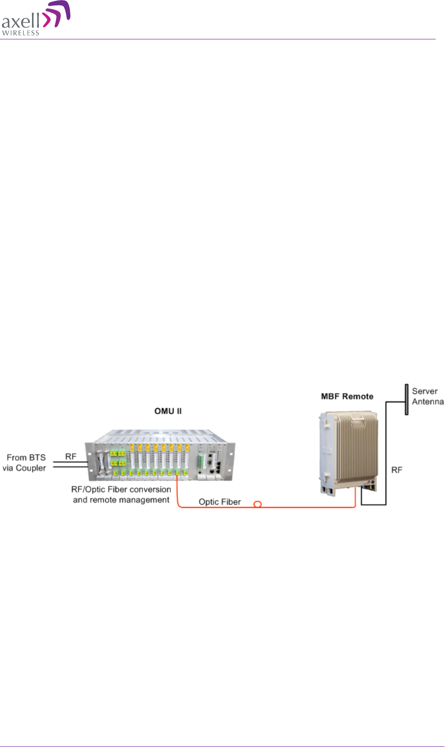
The Multi-Band Fiber optic fed system encapsulates solutions for both indoor and
outdoor environments for single or multi-operator use. It offers seamless coverage in
any indoor environment such as tunnels, subways and large buildings. Signals are
coupled off from a nearby base station using an Optical Master Unit (OMU) and then
distributed via Fiber to one or more MBF-40 repeaters.
The MBF-40's high output power allows for greater coverage whilst deploying fewer
units. Even though providing high output power, the MBF-40 uses convection cooling,
subsequently increasing the repeater's MTBF.
These remote units can be installed at a distance of up to 20 km from the base station
site, offering great flexibility when providing RF coverage in areas where off air
transmission is not a preferable solution.
A distributed antenna system (DAS) can be used to distribute the signal throughout the
area to be covered.
Axell Wireless can provide a complete solution including design, site surveys and
equipment related to the POI (Point Of Interface) such as combiners, filters, cross band
couplers, etc.
The MBF-High Power product family includes single, dual, triple and quad band options
conveniently co-located in a single, compact enclosure, as well as a five-band option
that requires an Slave unit.
Figure 1-1: Illustration of a standard OMU II MBF Remote Application

AXELL MBF -40 AMERICAS REPEATERS
PRODUCT DESCRIPTION AND USER’S MANUAL
2 Doc. No. 00071UM Rev. 3.4 © Axell Wireless Ltd
1.1 Features and Capabilities
• High-power indoor/outdoor unit, single-band, dual-band, tri-band, quad-band
models, supporting the following bands (model dependent):
• LTE 700MHz (Upper and Lower band)
• 700/800/900
• Cellular 850MHz
• PCS 1900MHz
• AWS 1700MHz (MIMO model available)
• 2600
• Up to four frequencies in a single enclosure
• Five-band single fiber-optic solution – implemented using two units MBF-40 Master
and MBF-40 Slave models
• Single enclosure MIMO support
• Output power at the antenna (composite): 37dBm, 39dBm, 43dBm (model
dependent)
• Very low noise factor - minimizes interference to BTS and increases high speed data
throughput
• Single or Dual Fiber feed models available
• Remote commissioning and monitoring:
• Via OMU II intuitive Web GUI
• Via AEM – no local setup required
• SNMP v1/v2c support
• Plug-and-Play: Automatic detection and Optical Gain Setting via the OMU
• Automatic Level Control (ALC) - provides constant gain in both uplink and downlink
paths according to the defined maximum output level
• Backup battery for ‘last gasp’ indication (sending fault error before power failure)
• Optional - two internal power supplies provided for some models ensure robust unit
operation
• Power source: 115VAC or -48V power (model dependent)
AXELL MBF-40 AMERICAS REPEATER
PRODUCT DESCRIPTION AND USER’S MANUAL
© Axell Wireless Ltd Doc. No. 00071UM Rev. 3.4 3
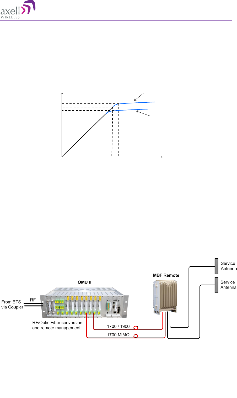
1.2 ALC
The repeater has a constant gain in both uplink and downlink paths. The repeater has a
defined maximum output level. If the input signal amplified by the gain set exceeds the
set output limit, an ALC (Automatic Level Control) loop is activated. This ALC ensures
that the amplifier does not add distortion to the radio signal. Below are examples of the
ALC function for one and two carriers.
Figure 1-2: ALC
1.3 MIMO Topology
MIMO configuration is supported by specific MBF-40 models. The physical casing of
these models supports two antenna ports and includes two (internal) optic conversion
modules (see section 1.7.3.4).
MBF-40 MIMO topology requires an OMU II unit that supports at least two sectors. Two
dedicated optic Fibers are routed from the OMU II towards the MBF-40.
Where relevant, MIMO specific installation instructions are provided in the manual.
Figure 1-3: MIMO OMU II-MBF-40 Remote Application
ALC one carrier
Input signal, dBm
Output power, dBm
+36,5
+33,8
-24 -16
Gain: 60 dB
+35
ALC two carriers
AXELL MBF -40 AMERICAS REPEATERS
PRODUCT DESCRIPTION AND USER’S MANUAL
4 Doc. No. 00071UM Rev. 3.4 © Axell Wireless Ltd
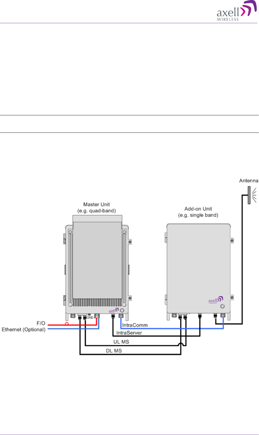
1.4 Five-Band Configuration
Cost effective five-band support over a single fiber-optic is implemented using two MBF-
units: MBF-40 Slave unit and MBF-40 Master unit. The Master unit can be either tri-band
or quad-band unit, where the Slave provides single-band or dual-band support for a
total of five bands.
All the services are routed to the Master unit via the optic fiber. The relevant (tri or
quad) services are filtered by the Master unit and forwarded along with the unfiltered
Slave services towards the Slave unit. At the Slave unit, the additional services are
filtered and all five services are routed towards the service antenna for distribution.
Five-Band System installation instructions are provided in section 3.4.
NOTE: The Web interface displays the five band service system as a single, 5-band unit. See Section
4.3.4. The connections between the two units are detailed in section 3.4.
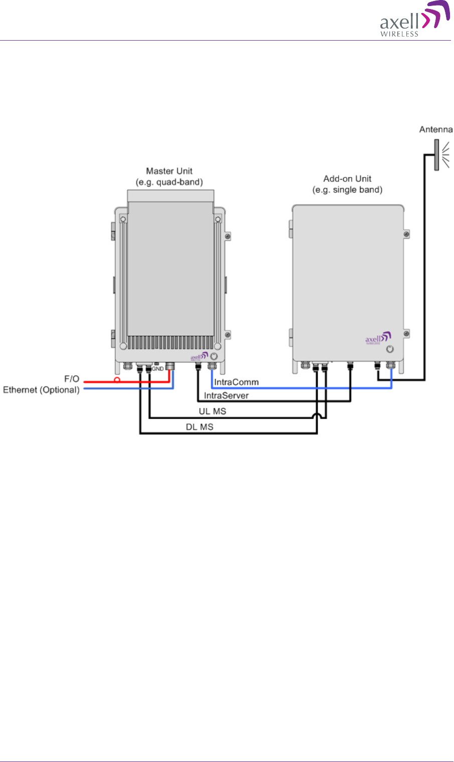
The following figure shows a Master/Slave configuration. The figure below shows a five
band configuration implemented using a quad-band Master and single-band Slave. The
example shows connections for a configuration WITHOUT external alarms.
Figure 1-4: Example of Five-band Configuration

AXELL MBF-40 AMERICAS REPEATER
PRODUCT DESCRIPTION AND USER’S MANUAL
© Axell Wireless Ltd Doc. No. 00071UM Rev. 3.4 5
1.5 Operating Temperature
The MBF-40 is designed primarily for multi carrier purposes. If the repeater is run at full
output power over a long period of time, additional, external cooling may be required;
this can take the form of air-conditioning or an external fan assembly.
Specific MBF-40 models, whose power consumption exceeds 400W, are provided with an
additional fan hood cooling assembly.
NOTE: The repeater is equipped with a power management function that steps down the power and,
if needed, fully shuts down the amplifier chains until temperature reaches normal values.
1.6 MBF-40 Management Web GUI
MBF-40 is remotely commissioned and monitored via an OMUII session. Local access to
the unit is not required for commissioning.
Additional configuration and troubleshooting options are available via a direct connection
to the MBF-40 IP address. A direct session can be opened locally or remotely.
NOTE: Direct remote communication requires connecting the MBF-40 to an Ethernet network.
1.7 MBF-40 Basic Interfaces
NOTE: This section describes the interfaces for MBF-40 models supporting up to four services and
whose power consumption does not exceed 400W. MBF-40 models, supporting five services and
with power consumption exceeding 400W are described in the relevant sections in chapter 3.
The MBF unit provides several types of interfaces:
• Lock and screws for protection and security
• External service antenna and GND connections
• Internal connections for power, Fiber optics and alarm cables routed via openings in
the screen.
• Internal USB and Ethernet connections for local setup via Web GUI
AXELL MBF -40 AMERICAS REPEATERS
PRODUCT DESCRIPTION AND USER’S MANUAL
6 Doc. No. 00071UM Rev. 3.4 © Axell Wireless Ltd
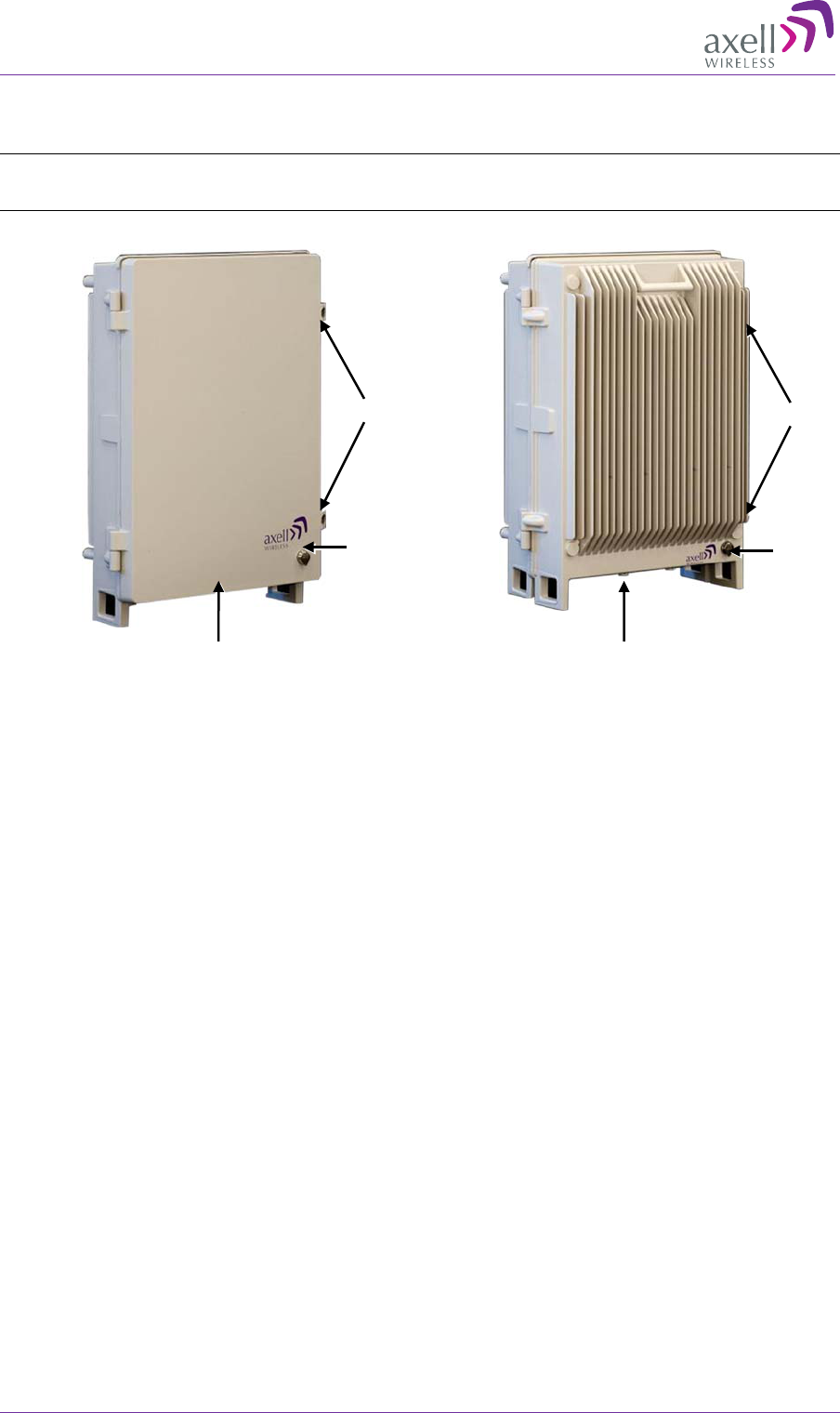
1.7.1 Securing the Unit
The repeaters are secured with two hex screws (M8) and can also be locked with a key.
NOTE: The two screws must be fully tightened. Failure to do so may affect the IP65 compliancy and
therefore any warranty.
Figure 1-5: Securing Single/Dual Band
Figure 1-6: Securing Tri/Quad Band
Screws
Lock
Connections
Screws
Lock
Connections
AXELL MBF-40 AMERICAS REPEATER
PRODUCT DESCRIPTION AND USER’S MANUAL
© Axell Wireless Ltd Doc. No. 00071UM Rev. 3.4 7
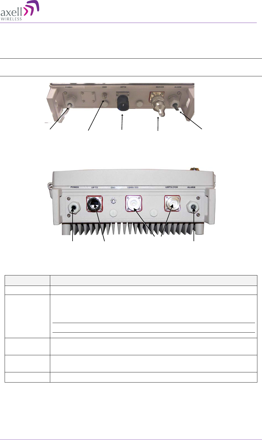
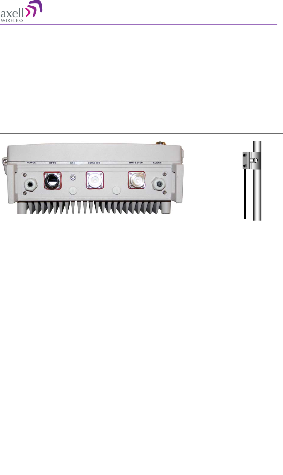
1.7.2 External Interfaces
The repeater’s interfaces are located on the underside. Two basic models are available:
single and dual service antennas.
NOTE: The external connections at the bottom of the repeater can be protected with a cover which is
screwed in place.
Figure 1-7: Single Service Antenna
Figure 1-8: Dual/MIMO Service Antenna
The following table provides a description of the front screenl ports and connections.
Port Description
Server Service antenna connection - DIN 7/16” connector, female
Optic SC/APC Fiber optic inlet through which the optic Fiber is routed for
internal connections (section 3.7).
For MIMO models – route the two Fibers via the Fiber port.
NOTE: Optic Fiber Conduit hose fitter may be pre-assembled.
Power Plinth connection for routing power for internal connection (section
3.9)
Alarms Plinth connector for routing external alarms and relay wiring cable
for internal connections (section 3.8).
GND Grounding lug (section 3.5)
Power Fiber inputGround Server
antenna External
alarms
Service
Antennas
Fiber Input
Power
Alarms

AXELL MBF -40 AMERICAS REPEATERS
PRODUCT DESCRIPTION AND USER’S MANUAL
8 Doc. No. 00071UM Rev. 3.4 © Axell Wireless Ltd
1.7.3 Internal Interfaces
This section shows the internal interfaces for various models. You will need to open the
Repeater in order to do the following:
• Connect power
• Connect optic Fibers
• Connect alarms (if relevant)
• Power-on (Power-ON switch)
• Optional – USB/Ethernet port for local setup
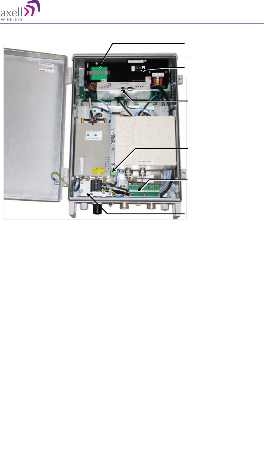
1.7.3.1 Single/Dual-Band Single Antenna Model
Figure 1-9: Single Band Repeater with Door Open
Alarms and relay connections (
section 3.8)
F/O Converter LEDs and optic
connector to which routed optic
fiber is connected (section 3.7)
Power connections
(section 3.9)
Controller module - USB local
setup connections. Refer to
section 7.4.1 for LED descriptions
Rechargeable backup
battery pack, see 3.9.6
Power and battery
switches. See section 3.9
Ethernet Local Setup port
AXELL MBF-40 AMERICAS REPEATER
PRODUCT DESCRIPTION AND USER’S MANUAL
© Axell Wireless Ltd Doc. No. 00071UM Rev. 3.4 9
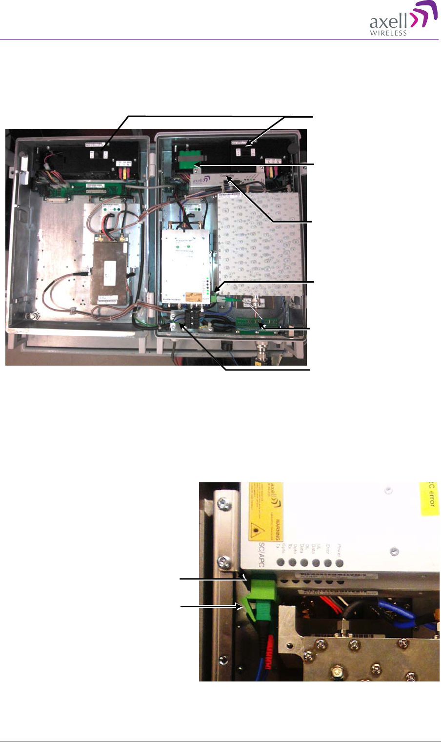
1.7.3.2 Dual-Band Dual-Antenna Model
Figure 1-10: Dual band Dual Service Antenna Model
F/O Converter LEDs and
optic connector to which
routed optic fiber is
connected (section 3.7)
Power connections
(section 3.9)
Controller module with
USB local setup
connections (section 7.4.1
for LED descriptions)
Rechargeable battery
pack (section 3.9.6)
Power and battery
switches (section 3.9)
Alarms and relay
connections (section 3.8)
AXELL MBF -40 AMERICAS REPEATERS
PRODUCT DESCRIPTION AND USER’S MANUAL
10 Doc. No. 00071UM Rev. 3.4 © Axell Wireless Ltd
1.7.3.3 Dual Power Supply
The figure below provides an example of a unit with a dual power supply. The internal
view of your unit may differ.
Figure 1-11: Dual band Dual Service Antenna Model
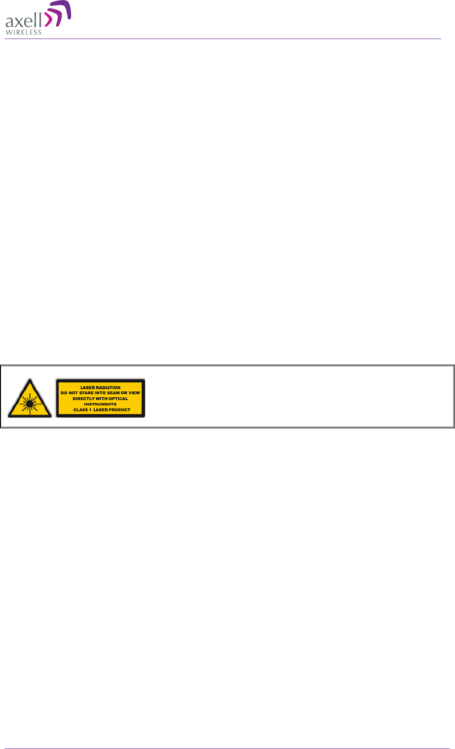
1.7.3.4 MIMO Model
The MIMO model includes two Service Antenna ports and two Optic Converter modules
(shown below). All other connections and interfaces are similar to the above models.
Figure 1-12: MIMO Model
Dual Fiber
optic
connectors to which
routed optic Fiber
s are
connected (section 3.7)
F/O Converter LEDs and
optic connector to which
routed optic fiber is
connected (section 3.7)
Power connections
(section 3.9)
Controller module with
USB local setup
connections. Section
7.4.1 - LED descriptions
Rechargeable battery
pack, See 3.9.6
Two Power Supplies (and
battery switches). Section
3.9
Alarms and relay
connections. Section 3.8.
AXELL MBF-40 AMERICAS REPEATER
PRODUCT DESCRIPTION AND USER’S MANUAL
© Axell Wireless Ltd Doc. No. 00071UM Rev. 3.4 11
2 Installation Requirements
This chapter provides information on the Remote installation site requirements, on the
installation requirements of the antennas, the specifications of the service antennas
suitable for operation with this remote and RF and F/O cable requirements.
2.1 MBF-40 Installation requirements
2.1.1 Safety Guidelines
Before installing the Repeater, review the following safety information:
• Follow all local safety regulations when installing the Repeater.
• Only qualified personnel are authorized to install and maintain the Repeater.
• Ground the Repeater with the grounding bolt located on the external lower side of
the Repeater).
• Do not use the grounding bolt to connect external devices.
• Follow Electro-Static Discharge (ESD) precautions.
• Use low loss cables to connect the antennas to the Repeater.
Class 1 Laser
This product is equipped with class 1 lasers, as per definition in EN 60825-1.
Caution!!!
Un-terminated optical receptacles may emit laser
radiation.
Do not stare into beam or view with optical instruments.
2.1.2 Criteria for Repeater Installation Location
The following criteria should be considered when selecting the Repeater installation site
location:
• Application type
• General surroundings
• Available installation
• Install the Repeater in a shielded, ventilated, and easy-to-reach area.
• Verify that there is a minimum of a 50 cm (20”) radius of space around the
Repeater, enabling easy access to the repeater for maintenance and on-site
inspection.
• Distance from antenna site - It is recommended that the installation location be as
close as possible to the antenna site in order to maintain the cable loss to a
minimum.
• The Repeater is convection cooled so airflow and alternation should be possible.
• Follow Electro-Static Discharge (ESD) precautions.
• Install the Repeater close to the service area to monitor the output power.
• Use low loss cables to connect the antennas to the Repeater.

AXELL MBF -40 AMERICAS REPEATERS
PRODUCT DESCRIPTION AND USER’S MANUAL
12 Doc. No. 00071UM Rev. 3.4 © Axell Wireless Ltd
2.1.3 RF Cable Installation Guidelines
• For all coaxial connections to/from the Repeater – use high performance, low-loss,
50 ohm coaxial communication cables.
• All cables shall be weather-resistant type.
• Cable length – determined by the Repeater installation plan. When calculating the
cable length, take into account excess cable slack so as not to limit the insertion
paths.
• Make sure the cable and the connector are compatible. Using cables and connectors
from the same manufacturer is helpful.
• All connectors must be clean and dry.
• Waterproof all outdoor connections using silicon, vulcanizable tape or any other
suitable substance, as moisture and dust can impair RF characteristics
• Make sure enough room has been allocated for the bending radius of the cable. RF
cables must not be kinked, cut or damaged in any way.
• Connect the RF cable to the antenna tightly but without damaging threads.
• Fasten cable tightly to cable ladder or aluminium sheet.
• For short length feeder cables, use 1/2”; for longer feeder cables, use 7/8”. Choose
thicker coax cables for lower attenuation. Minimize the length of the coax cables to
reduce attenuation.
• Use jumper cable for easy installation. The RF coaxial cable can be substituted at
each end with a jumper cable.
2.1.4 F/O Cable Installation Guidelines
Use the following over the complete link between the Remote and OMU:
• Use angled APC connectors at 8deg angle.
• APC type ODF connections.
• Cable length - determined by the Remote installation plan. When calculating the
cable length, take into account excess cable slack so as not to limit the insertion
paths.
Recommended Fiber-optic cable:
• Single mode 9/125

AXELL MBF-40 AMERICAS REPEATER
PRODUCT DESCRIPTION AND USER’S MANUAL
© Axell Wireless Ltd Doc. No. 00071UM Rev. 3.4 13
2.2 Service Antenna Requirements (English)
This section provides information on the specifications of the service antennas suitable
for operation with this repeater, on the installation requirements of the antennas and on
the Repeater installation site and cable requirements.
ATTENTION!!
• The installer is held accountable for implementing the rules required for deployment.
• Good engineering practice must be used to avoid interference.
• Output power should be reduced to solve any IMD interference issues.
• The installation height of the antenna for AWS band (1700/2100 MHz) operations is
limited to 10 meters above ground for compliance with 47 CFR 27.50.
2.2.1 Required Antenna Information
The following antenna requirements, specifications and site considerations should be
met.
• Type of installation – indoor or outdoor
• Service area type and size
• Antenna type and characteristics
• Height
• Length and type of coaxial cable required for connecting the Service antenna to the
Remote and the attenuation.
2.2.2 Recommended Antennas
The Service antenna is installed indoors, where the type of antenna depends on the
application.
Specifications:
• One or a combination of the following antennas can be used: Ceiling Mount Patch
antenna, Wall Mount Patch antenna, Corner Reflector.
• Choose an antenna with high side lobe attenuation which enables maximum isolation
from other service/ mobile antennas.
• Net gain [Gain Antenna – Cable loss] must not exceed 9 dBi
• Antennas with gain < 9 dBi can be connected directly to the MBF-40 ports.
• Higher gain antennas may be connected to the MBF-40 ports along with adequate
cable and splitting losses
Typical antenna types:
• Indoor Dome 2.1 dBi; beam width 360°
• Indoor Panel 4.2 dBi; beam width 106°
• Radiating Cable Typically < -50 dBi
AXELL MBF -40 AMERICAS REPEATERS
PRODUCT DESCRIPTION AND USER’S MANUAL
14 Doc. No. 00071UM Rev. 3.4 © Axell Wireless Ltd
2.2.3 Recommended Splitters and Couplers
2.2.3.1 Recommended Splitters
Splitter part numbers 90 - 851102 90 - 851103 90 – 851104
Frequency band 700 – 2700 MHz 700 – 2700 MHz 700 – 2700 MHz
Split 2 way 3 way 4 way
Max Insertion Loss 0.4 dB 0.6 dB 0.6 dB
Split Loss 3 dB 4.8 dB 6 dB
2.2.3.2 Recommended Couplers
Coupler part numbers 90 - 852206 90 - 852210 90 – 852215 90 – 852220
Frequency band 700-2700 MHz 700–2700 MHz 700–2700 MHz 700–2700 MHz
Coupling -6dB ±0.8dB -10dB ±1.0dB -15dB ±1.0dB -20dB ±1.0dB
Max Mainline Loss 1.7 dB 0.8 dB 0.4 dB 0.22 dB
2.3 Service Antenna Requirements (French)
Cette section fournit des informations sur les spécifications du donneur et des antennes
de services adaptés pour fonctionner avec ce répéteur, sur les conditions d'installation
des antennes et sur le site d'installation de répéteur et exigences de câblage.
ATTENTION!!
• L'installateur est tenu pour responsable de la mise en œuvre des règles
nécessaires au déploiement.
• Les bonnes pratiques d'ingénierie doit être utilisée pour éviter les interférences.
• Puissance de sortie doit être réduite pour résoudre tous les problèmes
d'interférence de l'IMD.
2.3.1 Antenne Informations Requises
Les exigences d'antenne suivants, les spécifications et considérations du site doivent
être remplies:
• Type d'installation - à l'intérieur ou à l'extérieur
• Type de zone de service et la taille
• Type et les caractéristiques de l'antenne
• Hauteur
• La longueur et le type de câble coaxial requis pour relier l'antenne au répéteur et
l'atténuation.

AXELL MBF-40 AMERICAS REPEATER
PRODUCT DESCRIPTION AND USER’S MANUAL
© Axell Wireless Ltd Doc. No. 00071UM Rev. 3.4 15
2.3.2 FCC et IC conformité de l'installation intérieure
L'antenne de service est installé à l'intérieur, où le type d'antenne dépend de
l'application.:
• Un ou une combinaison des antennes suivantes peuvent être utilisées: Antenne
Patch pour montage au plafond, antenne Patch pour montage mural, Réflecteur en
Coin.
• Choisissez une antenne à haute côté atténuation du lobe qui permet une isolation
maximum des autres services / antennes mobiles.
• Gain net [Gain Antenna - la perte de câble] ne doit pas dépasser 9 dBi
• Les antennes à gain < 9 dBi peut être connectée directement aux ports MBF-40.
• Antennes à gain plus élevées peuvent être connectés aux ports MBF-40 avec des
pertes de câble et de division adéquates.
2.3.3 Critères d'installation de l'antenne d'installation d'intérieur
Déterminer la configuration de l'installation de l'antenne, selon les exigences de
transmission et les conditions du site d'installation.
Exigences d'installation:
• Une antenne intérieure doit être installée à un endroit pratique. Il doit être libre de
tout obstacle métallique.
• Installez l'antenne de service à la hauteur désignée et l'accorder à peu près vers la
zone de couverture du service.
• L'installation de cette antenne doit fournir une distance minimale de séparation de
110 cm de tout le personnel dans la région
2.3.4 Indoor Installations Service/Mobile Antenna Requirements
Determine the antenna installation configuration, according to the transmission
requirements and the installation site conditions.
Installation requirements:
• An indoor antenna should be installed at a convenient location. It should be free of
metallic obstruction.
• Install the Service Antenna at the designated height and tune it roughly toward the
Service coverage area.
2.3.5 Outdoor Installations
For applications in which the Service/Mobile antenna is installed outdoor, the antenna
type is chosen according to the available infrastructure (single-pole or horizontal
installation). In addition, isolation between the donor and service antennas must be
taken into account when selecting the location of the antennas.
AXELL MBF -40 AMERICAS REPEATERS
PRODUCT DESCRIPTION AND USER’S MANUAL
16 Doc. No. 00071UM Rev. 3.4 © Axell Wireless Ltd
3 Repeater Installation
This chapter describes the installation of various repeater models, including repeaters
with fan assemblies (section 3.3) and five service Master / Slave systems (section 3.4).
WARNING!! Maximum input power should not exceed (zero) 0 dBm
3.1 Location Criteria
Location criteria
• Wall compatibility - check the suitability of the wall on which the MBF-40 is to be
to be fitted.
• Plan mount - check the actual fixing centres (see below) and overall dimensions of
the MBF-40 enclosure. The MBF-40 is supplied with two wall mounting brackets;
when the MBF-40 is mounted on these brackets adequate ventilation is provided
between the MBF-40 and the wall to which it is fixed.
• Plan connection cable clearances - the Optical, RF and power connections located
on the underside of the MBF-40 will need at least 300mm vertical clearance below
the MBF-40 to enable the connections to be made. The minimum bend radius for
Optical and RF cables must not be less than the recommendations made by the cable
manufacturer. Plan the cable runs and ensure adequate space is available.
• Allow for door opening - ensure that there is sufficient space at the front of the
MBF-40 to allow the door to be fully opened and for maintenance engineers to get
access to the unit with test equipment such as a spectrum analyzer. Allow an
additional 500mm of space in front of the MBF-40 when the door is fully open.
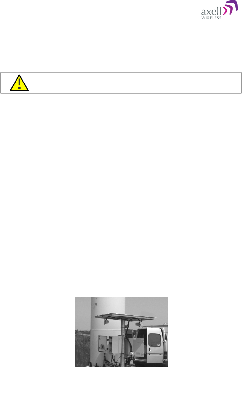
• Allow for heat dispersion - Mount the repeater so that heat can be dispersed from
it.
The repeater wall mounting kit ensures an optimum airflow between the wall and the
repeater.) Do not block this air channel as it will cause the MTBF of the repeater to
drop dramatically, or even in the worst case cause the repeater to fail completely.
If possible, use a wall in the shade to minimize the overall sun loading. If sufficient
shielding cannot be obtained, an additional sun shield should be mounted.
Figure 3-1: Example of a sun shield
AXELL MBF-40 AMERICAS REPEATER
PRODUCT DESCRIPTION AND USER’S MANUAL
© Axell Wireless Ltd Doc. No. 00071UM Rev. 3.4 17
3.2 Standard Repeater Installation
NOTE: Refer to this section if your repeater installation does not consist of either a fan assembly or a
Master / Slave (five service) system.
3.2.1 Unpacking
Upon receiving the MBF-40 Repeater perform the following:
1. Examine the shipping container for damage before unpacking the unit.
2. Perform a visual inspection to reveal any physical damage to the equipment.
3. Verify that all of the equipment (listed below) is included. Otherwise contact Axell
Wireless Ltd. The MBF-40 Repeater is shipped with the following equipment:
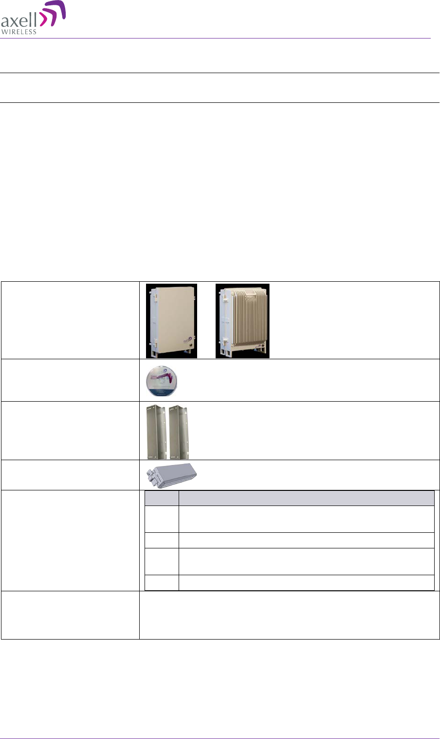
3.2.2 Parts List
Package Contents
MBF-40
Single/Dual/Tri/Quad-
band Repeater
CD containing User’s
Manual and USB driver
Mounting Brackets
Cable protection KPL
Additional (supplied)
installation components:
Qty. Description
4x
M8x12 bolts for securing the Repeater to the
brackets
1x Insex tool for bolts
1x Fiber Conduit inlet hose fitter (may be pre-
assembled)
1 x Key
Optional equipment AC Cable [30 ft.] – Long cable for AC power
Alarm Cable [30 ft.] – Long cable for External Alarms
Input
AXELL MBF -40 AMERICAS REPEATERS
PRODUCT DESCRIPTION AND USER’S MANUAL
18 Doc. No. 00071UM Rev. 3.4 © Axell Wireless Ltd
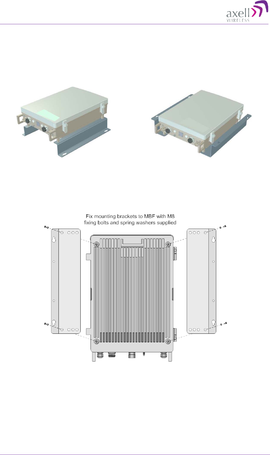
3.2.3 Bracket Assembly
The repeater can be mounted on the wall or in a 19 inch rack.
Using the 4 provided M8 Fixing bolts and 4 spring washers assemble the brackets as
illustrated below – according to your required mounting location (wall or rack).
Figure 3-2: Wall mount bracket position
Figure 3-3: Rack-mount bracket position
• Fix mounting brackets to MBF – use the supplied four M8 bolts and spring
washers.
Figure 3-4: Fix mounting brackets to MBF
AXELL MBF-40 AMERICAS REPEATER
PRODUCT DESCRIPTION AND USER’S MANUAL
© Axell Wireless Ltd Doc. No. 00071UM Rev. 3.4 19
Figure 3-5: Mounting Plates Fixed to MBF
3.2.4 Wall Marking and Drilling
• The Repeater wall mount brackets assembly should be fixed to a solid wall (these
include brickwork, blockwork, and concrete.);
WARNING!! Due to the weight of the Repeater, it is NOT recommended to fix to a
hollow wall).
• To provide secure fixing to a solid wall, the most common method is drilling and
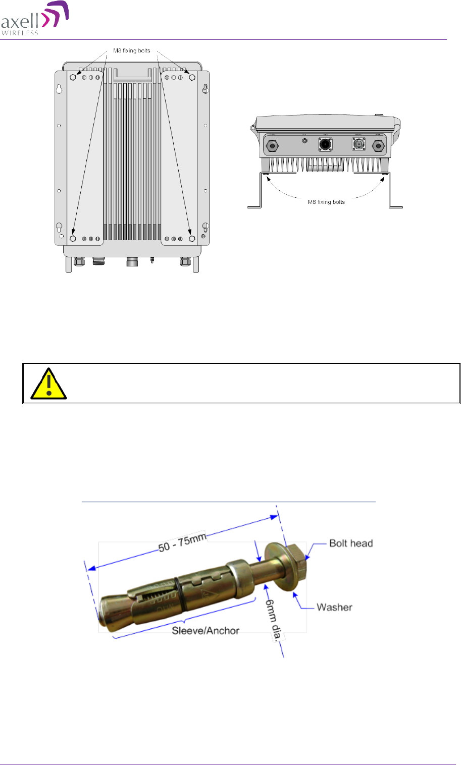
plugging. The size of fixing is dependent on the item to be fixed and the nature of
the wall, The Repeater should be fixed with mild steel, M6 (50mm to 75mm)
rawlbolts or similar.
• Care must be taken to ensure the alignment of the four fixings. A spirit level or
plumb line should be used to ensure horizontal/vertical alignment.
Figure 3-6: M6 Rawlbolt – recommended for wallmount.
AXELL MBF -40 AMERICAS REPEATERS
PRODUCT DESCRIPTION AND USER’S MANUAL
20 Doc. No. 00071UM Rev. 3.4 © Axell Wireless Ltd
IMPORTANT!! Always check that there are no pipes or cables hidden in the wall
beneath the area to be drilled. Various pipe and cable detectors are available for this
type of inspection.
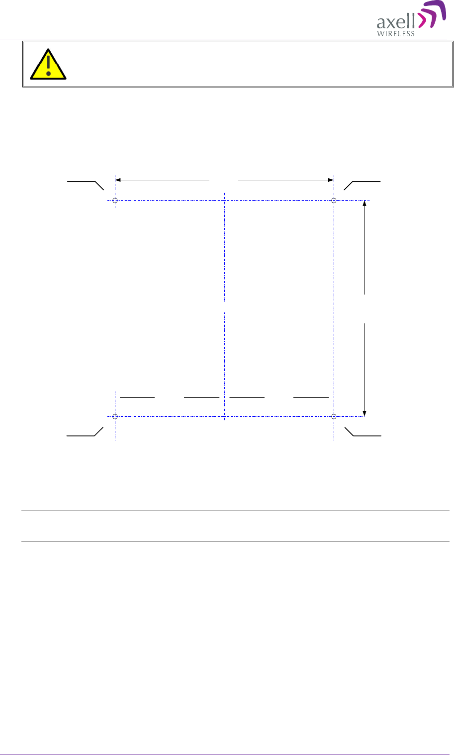
To mark and drill the wall
1. Mark out the fixing centres of the repeater on the chosen wall. Refer to the repeater
dimensions are shown below.
Figure 3-7: Fixing Centres
2. Mark and drill the wall with the correct size masonry bit as specified by the fixing
manufacturer.
NOTE: It is good practice to wear goggles to protect your eyes from flying debris when using
power tools.
3. Hold the drill bit against the mark and begin drilling slowly so that the bit does not
wander from the position. The wall should be drilled to a depth which is sufficient to
accommodate the full length of the fixing.
4. Insert the fixings so that the top of the sleeve/anchor section is level with the wall
surface.
368mm
378mm
Hole to take
M6 rawl bolt
Hole to take
M6 rawl bolt
189mm 189mm
Centre Line of MBF
Hole to take
M6 rawl bolt
Hole to take
M6 rawl bolt
AXELL MBF-40 AMERICAS REPEATER
PRODUCT DESCRIPTION AND USER’S MANUAL
© Axell Wireless Ltd Doc. No. 00071UM Rev. 3.4 21
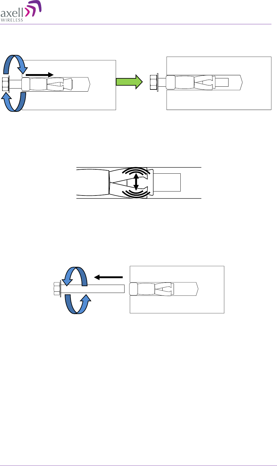
5. Gently tighten the bolt by hand so that the anchor section of the fixing expands and
grips the inside of the hole.
Figure 3-8: Inserting Fixing and Tightening.
6. As the bolt pulls its way in, the sides of the anchor section are forced outwards,
gripping the surrounding surface.
Figure 3-9: Anchor Sides Pushed Outwards.
7. Once all four fixings are in place, carefully withdraw the four bolts.
Figure 3-10: Withdraw Bolts.
AXELL MBF -40 AMERICAS REPEATERS
PRODUCT DESCRIPTION AND USER’S MANUAL
22 Doc. No. 00071UM Rev. 3.4 © Axell Wireless Ltd
3.2.5 Mount the Repeater
CAUTION!!! It is recommended that two people lift the repeater since (depending
upon the configuration) the MBF-40 weighs between 20 and 38 kg (44 and 84 llb)
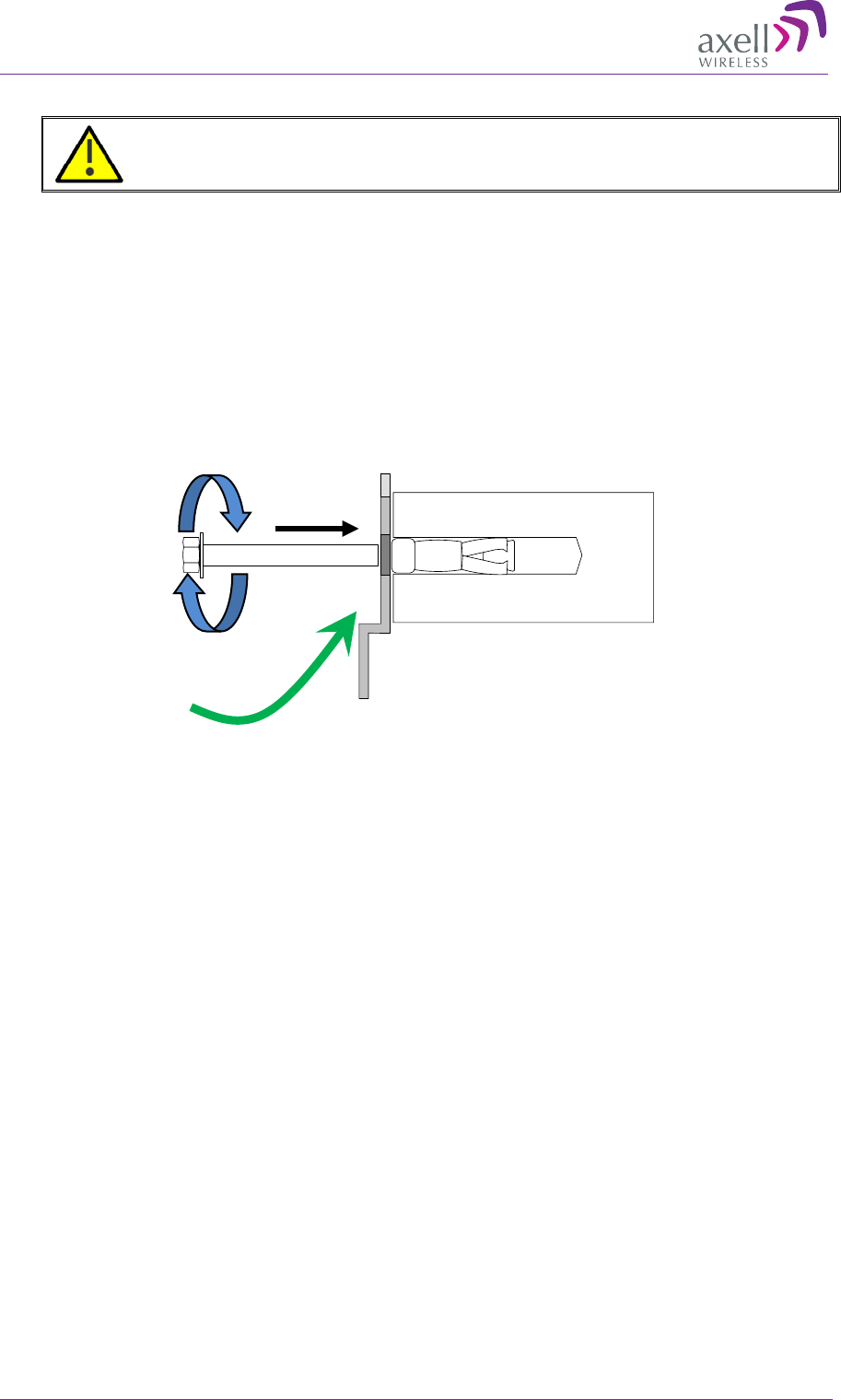
To mount the repeater
• Align repeater with the four fixings. Great care should be exercised here as the
repeater is very heavy. (A suitably rated heavy duty scissor lift table/trolley may be
suitable for this operation.)
• Once repeater is held in the chosen position, carefully insert the fixing bolts through
the mounting lugs of the Repeater and into the sleeve/anchor sections of the fixing
in the wall and tighten the bolts.
• The repeater needs to be mounted tightly to eliminate vibration.
Figure 3-11: Mount Repeater
Align Repeater and
Secure Bolts
AXELL MBF-40 AMERICAS REPEATER
PRODUCT DESCRIPTION AND USER’S MANUAL
© Axell Wireless Ltd Doc. No. 00071UM Rev. 3.4 23
3.3 Repeater with Fan Hood Installation
Some repeater models with power consumption exceeding 400W are supplied with a
fan-hood assembly kit. This section describes the bracket and fan assemblies for the
relevant repeater models.
WARNINGS!!!
• The fan modules can only be assembled on the appropriate repeater
models.
• This installation requires two people.
The following figure shows the assembled system. It includes the mounting brackets and
two fan assembly units. The dimensions, parts list and assembly instructions are
provided in the following sections.
Figure 3-12: MBF-40 including Fan Hood
2x Mounting
Brackets (one on
each side)
Rear Fan
Hood
Front Fan
Hood
Fan Hood Power
Interfaces (2)
AXELL MBF -40 AMERICAS REPEATERS
PRODUCT DESCRIPTION AND USER’S MANUAL
24 Doc. No. 00071UM Rev. 3.4 © Axell Wireless Ltd
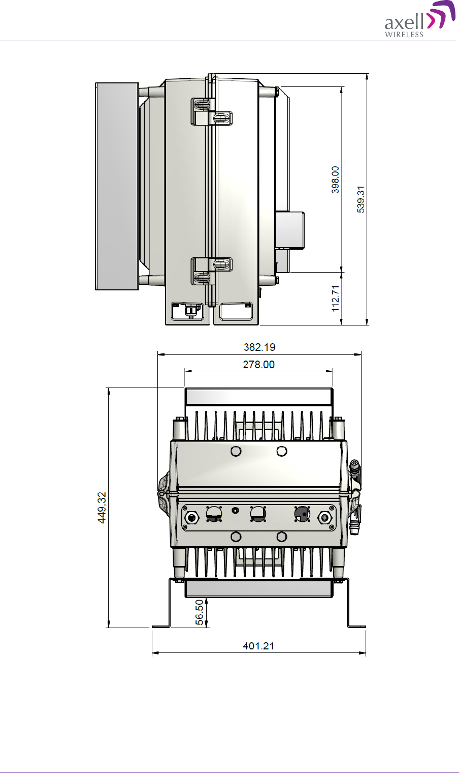
3.3.1 Dimensions
Figure 3-13: MBF-40 including Fan Hood – Assembly Dimensions
AXELL MBF-40 AMERICAS REPEATER
PRODUCT DESCRIPTION AND USER’S MANUAL
© Axell Wireless Ltd Doc. No. 00071UM Rev. 3.4 25
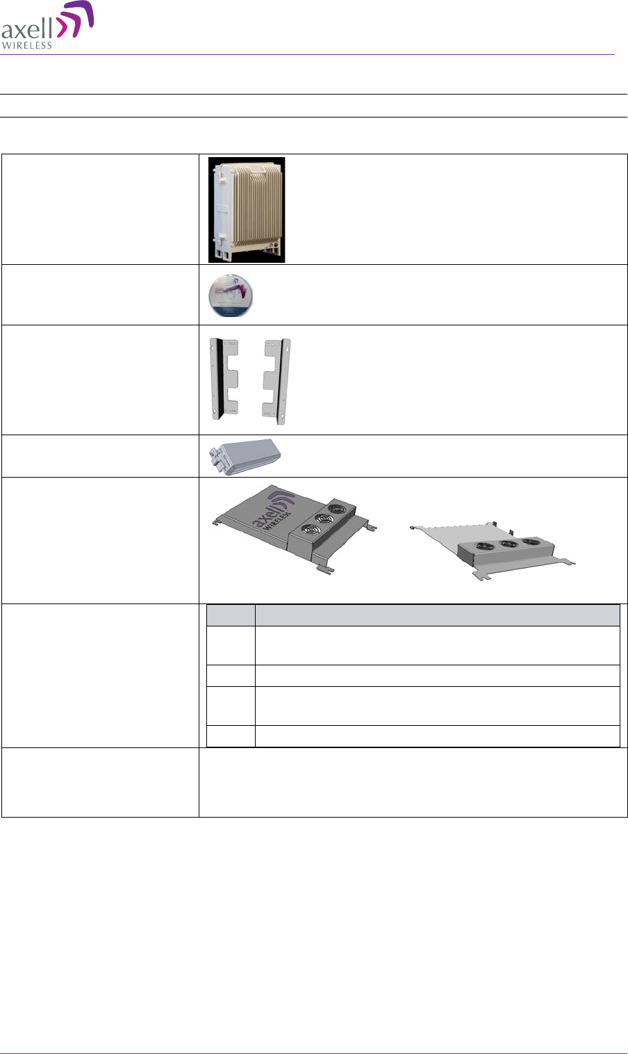
3.3.2 Parts List
NOTE: The Front Fan Hood and the Rear Fan Hood are NOT interchangeable.
Package Contents
MBF-40 Repeater
CD for OMU II and MBF
Variants EMEA/Americas
Mounting Brackets
Cable protection KPL
Front Fan Hood
Rear Fan Hood
Rear fan hood (no edges) Front fan hood (edged)
Additional (supplied)
installation components:
Qty. Description
6x
M8x12 bolts and washers for securing the
Repeater to the brackets and fan hoods
1x Insex tool for bolts
1x Fiber Conduit inlet hose fitter (may be pre-
assembled)
1 x Key
Optional equipment AC Cable [30 ft.] – Long cable for AC power
Alarm Cable [30 ft.] – Long cable for External Alarms
Input
AXELL MBF -40 AMERICAS REPEATERS
PRODUCT DESCRIPTION AND USER’S MANUAL
26 Doc. No. 00071UM Rev. 3.4 © Axell Wireless Ltd
3.3.3 Fan Hood and Bracket Assembly
WARNING!!
• This Fan Hood is to be assembled only on the MBF-40 units for which it is
designed and with which it is supplied.
• Do NOT assemble this fan hood on any repeater models for which it is not
specifically designed.
• Be sure to CAREFULLY follow all instructions – beginning with Step-1.
The fan hood and bracket assembly procedure is as follows:
• Assemble rear fan hood and mounting brackets
• Mount the repeater on the wall
• Assemble the front fan hood
• Connect power to both fan hoods
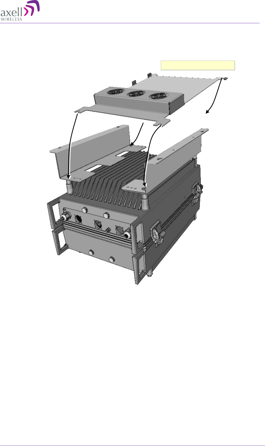
To assemble the fan hood
1. Place the repeater on a flat surface, repeater door panel facing down, interfaces
towards you.
2. Loosely assemble the mounting brackets:
• Align innermost bracket holes to repeater mounting holes.
• Loosely insert bolts and washers.
Figure 14: Place Brackets on top the MBF
Repeater front door
panel facing down
Align
brackets and
loosely
insert x4 bolts and washers
AXELL MBF-40 AMERICAS REPEATER
PRODUCT DESCRIPTION AND USER’S MANUAL
© Axell Wireless Ltd Doc. No. 00071UM Rev. 3.4 27
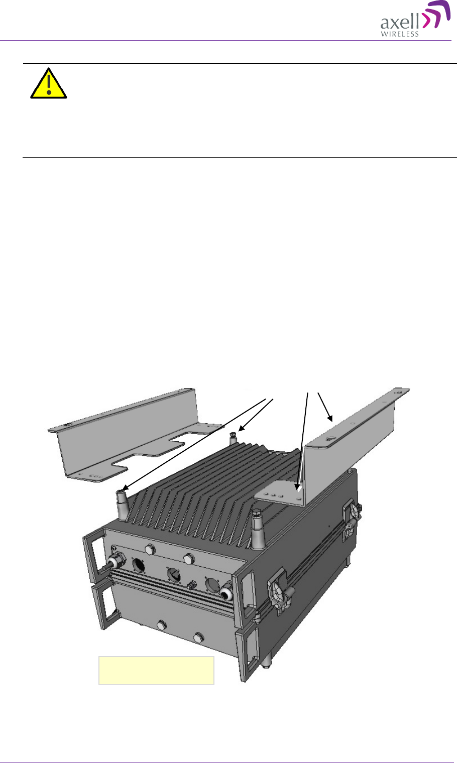
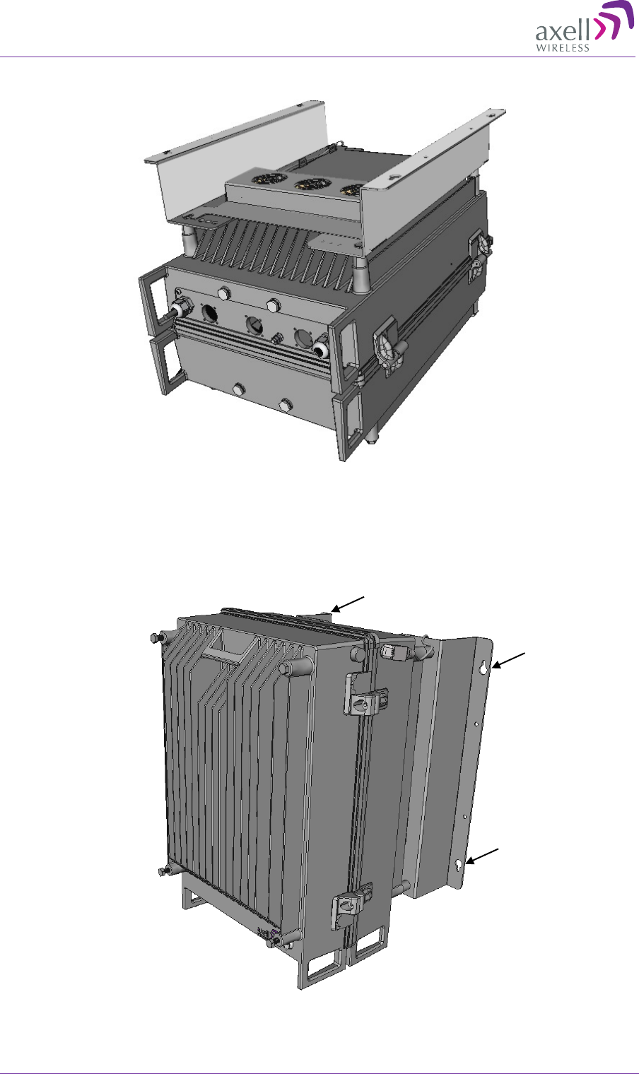
3. Assemble Rear Fan Hood:
• Position the Rear Fan Hood under the (inserted) bolts and washers.
• Tighten the four bolts.
Figure 3-15: Assemble Rear Fan Hood
Position under bolts
and tighten bolts
Fan Hood panel on top
AXELL MBF -40 AMERICAS REPEATERS
PRODUCT DESCRIPTION AND USER’S MANUAL
28 Doc. No. 00071UM Rev. 3.4 © Axell Wireless Ltd
The brackets and Rear Fan Assembly is shown below.
Figure 3-16: Assembled Rear Fan Hood and Mounting Brackets
4. Referring to the MBF-40 User’s Manual, prepare the mounting area and hang the
repeater on the wall:
• Drill the holes in the wall.
• Mount the Repeater.
Figure 3-17: Mount the Repeater
Prepare mounting area
and mount repeater
AXELL MBF-40 AMERICAS REPEATER
PRODUCT DESCRIPTION AND USER’S MANUAL
© Axell Wireless Ltd Doc. No. 00071UM Rev. 3.4 29
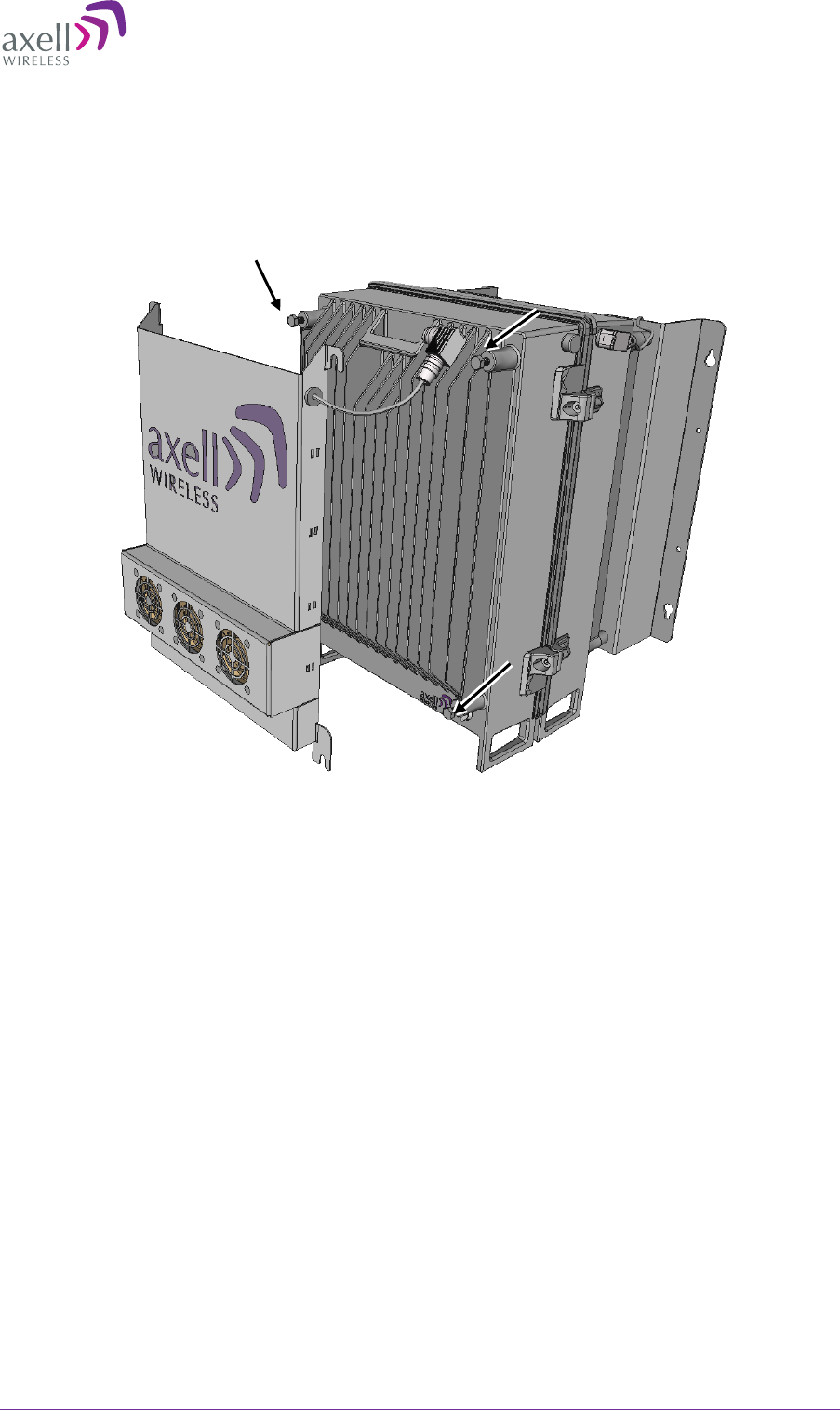
5. Assemble Front Hood Fan:
• Loosely insert the x4 M8x12 bolts and washers.
• Hang the Front Fan Hood on the repeater and tighten the bolts.
Figure 3-18: Insert the Two M8x12 Bolts
Loosely insert x4
bolts and washers
Hang the Front Fan Hood
on the bolts and tighten
AXELL MBF -40 AMERICAS REPEATERS
PRODUCT DESCRIPTION AND USER’S MANUAL
30 Doc. No. 00071UM Rev. 3.4 © Axell Wireless Ltd
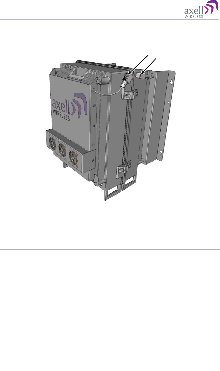
6. Fan Hood power connections:
Connect the Front Fan Hood and the Rear Fan Hood power connectors to the
Repeater power connectors.
Figure 19: Slide Front Fan Hood onto MBF
3.4 Five-Band System Installation
NOTE: Both Master MBF-40 and Slave MBF-40 (5-band system) unit models differ from the
standard MBF-40 single-clamshell and dual-clamshell models. The installation of the latter models is
described in section 3.2
This section describes the installation procedure for a five-band system. The 5-band
system consists of two units: Master MBF-40 and Slave MBF-40. All the services are
routed to the Master unit via the optic fiber, where the Master and Slave are managed
as a single unit via the Master connections.
Connect power of Rear and
Front Fan Hood assemblies

AXELL MBF-40 AMERICAS REPEATER
PRODUCT DESCRIPTION AND USER’S MANUAL
© Axell Wireless Ltd Doc. No. 00071UM Rev. 3.4 31
3.4.1 Required Items for a Master Slave System
In addition to the items provided in the Master/Slave Repeater package, you will require
the following cables for interconnecting the Master Slave units:
• 2 high power 50ohm coaxial (jumper) cables with N male connectors on both side
• 1 low loss, high quality 50ohm jumper cable with 7/16 male connectors on both side
• 1 standard straight CAT5 (or above) Ethernet cable with RJ45 connectors on both
side
NOTE: The length of the cables depend on the distance that the Master and Slave units are mounted
from each other.
3.4.2 Mounting the Master and Slave Units
The Master and Slave units are mounted near each other on the wall.
ATTENTION!!! Recommended distance between the units depends on RF jumper cables used and
their loss. Maximum distance for low less cables ~5m
To mount the Master and Slave Units
1. Mark the intended location of the Master and Slave units on your wall.
2. Mount the Master as follows:
• For Master units provided WITH a Fan Hood assembly kit, mount according
to section 3.3.
• For Master units WITHOUT a Fan Hood assembly kit, mount according to
section 3.2.
3. Mount the Slave unit according to section 3.2.
AXELL MBF -40 AMERICAS REPEATERS
PRODUCT DESCRIPTION AND USER’S MANUAL
32 Doc. No. 00071UM Rev. 3.4 © Axell Wireless Ltd
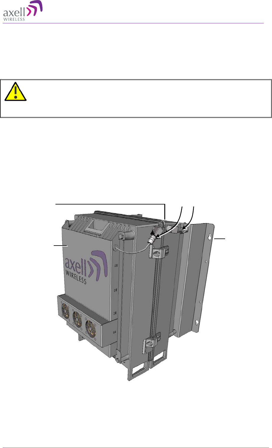
3.4.3 Connecting Master and Slave Units
The following figure provides and example of a five band configuration implemented
using a quad-band Master and single-band Slave.
The connections vary depending on whether external alarms are connected. The figure
below shows the connections WITHOUT external alarms.
Figure 3-20: Connections WITHOUT External Alarms

AXELL MBF-40 AMERICAS REPEATER
PRODUCT DESCRIPTION AND USER’S MANUAL
© Axell Wireless Ltd Doc. No. 00071UM Rev. 3.4 33
To connect the Master and Slave (refer to the previous figure)
1. GND BOTH the Master and Slave units according to section 3.5.
2. Ensure good EMV protection according to section 3.6.
3. Interconnect Master and Slave as follows:
• 2 high quality 50ohm coaxial (jumper) cables with N male connectors on both side
• 1 low loss, high quality 50ohm jumper cable with 7/16 male connectors on both side
• 1 standard straight CAT5 (or above) Ethernet cable with RJ45 connectors on both
side
MASTER Port SLAVE Port Description CABLE Type
(section 0)
SERVER LINK INPUT Jumper cable with
7/16 male
connectors
DL MS
DL MS Downlink intermediate
connector Master-Slave RF Low Power
50ohm coaxial
(jumper) cable with
N male connectors
UL MS UL MS UL intermediate
connector Master-Slave 50ohm coaxial
(jumper) cable with
N male connectors
IntraComm IntraComm If NO external
alarms are
connected: LAN/
CAT5
(If external alarms
are connected, refer
to section 3.4.4)
4. Route the following cables through the MASTER DONOR port and connect internally:
Cable Condition Details
Optic Fibre Always See section
ETH (opt) If the unit is to be
connected to the
Ethernet
infrastructure
To the Controller ETH port.
See section 1.7.3
5. Connect the Server antenna to the SLAVE unit Server antenna port as illustrated.
6. Connect power, power-up, close and secure both units according to sections 3.9,
3.10 and 3.11.
AXELL MBF -40 AMERICAS REPEATERS
PRODUCT DESCRIPTION AND USER’S MANUAL
34 Doc. No. 00071UM Rev. 3.4 © Axell Wireless Ltd
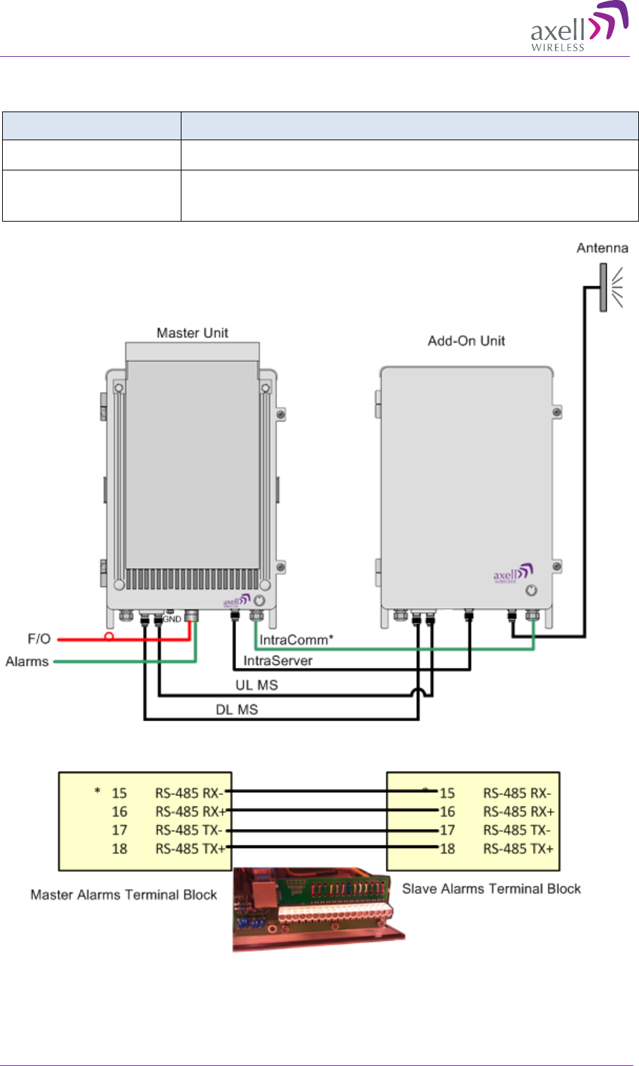
3.4.4 Master/Slave Connections for External Alarms
To connect external alarms, modify the connections to the Master and Slave as follows:
Port location Connection type and details
Master DONOR port Route and connect ALARMS according to section 3.8
IntrComm
(Master to Slave)
Interconnect RS-485 internal bus of
MASTER and of SLAVE
according to the following figure.
Figure 3-21: Connections WITH External Alarms
AXELL MBF-40 AMERICAS REPEATER
PRODUCT DESCRIPTION AND USER’S MANUAL
© Axell Wireless Ltd Doc. No. 00071UM Rev. 3.4 35
3.5 Grounding
Connect the grounding protection as follows:
• Ensure that good grounding protection measures are taken to create a reliable
repeater site.
• Make sure to use adequately dimensioned grounding cables. The minimum
recommended conductive area for a grounding cable is 16mm2
• Make sure the grounding product used is suitable for the kind and size of cable being
used.
• Connect the repeater box bolt to the same ground.
NOTE: For Dual Unit assemblies (five frequency band support), ground both units.
Figure 3-22: Grounding the MBF-40
AXELL MBF -40 AMERICAS REPEATERS
PRODUCT DESCRIPTION AND USER’S MANUAL
36 Doc. No. 00071UM Rev. 3.4 © Axell Wireless Ltd
3.6 Ensure Good EMV Protection
CAUTION!!! If insufficient
Electromagnetic Protection is provided, or if EMV
measures are not taken, warranties issued by Axell Wireless are not valid.
Connect the lightning protection
The lightning hazard to electric and electronic equipment consists in the interferences of
direct lightning current infections and high surge voltages induced by the
electromagnetic field of nearby lightning channels or down conductors. Amplitudes from
cloud-to-earth lightning amounts to several 10kA and may last longer than 2ms. The
damage caused depends on the energy involved and on the sensitivity of the electronics
systems.
Ensure that lightning protection measures are taken to create a reliable repeater site.
Protect all coaxial cables and power cables from the transients caused by lightning. Fit
all cables with suitable lightning protection devices.
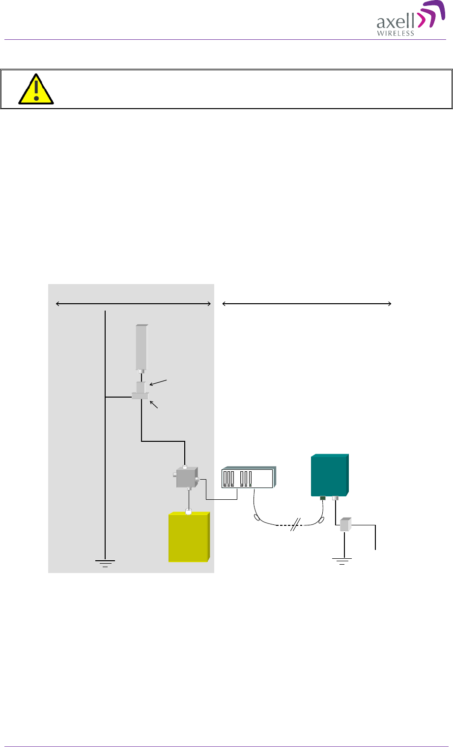
Figure 3-23: Example of EMV protection for a repeater system
For detailed information please refer to IEC 61024-1 and 61312-1 for international
standards for protection of information systems against LEMP (Lightning Electromagnetic
Pulse), including radio transmitters. They define proper planning, installation and
inspection of effective lightning protection systems.
The Axell Wireless repeaters comply with the EN standard ETS 301 498-8 which
stipulates demands on lightning/surge protection for typical infrastructure telecom
equipment installations.
Repeater
Fiber
BTS
-30dB
Coupler
OMU
Antenna
Primary
Protective
Device
Equipotential
Grounding Bar
230VAC/
-48VDC
Protective
Device
The top of
the mast
must be
higher than
the antennas
and be
grounded
properly
The
grounding
path must
have reliable
continuity
and be
dimensioned
correctly
BTS area Repeater area
AXELL MBF-40 AMERICAS REPEATER
PRODUCT DESCRIPTION AND USER’S MANUAL
© Axell Wireless Ltd Doc. No. 00071UM Rev. 3.4 37
Several lightning protection devices should be used in series with declining threshold
voltages to help attenuate the pulse component which makes it through the first layer of
protection.
The primary protective device is part of the site installation and is not supplied by Axell
Wireless. Coaxial lightning protection is normally one of these three types: Gas capsule,
High-pass and Bandpass.
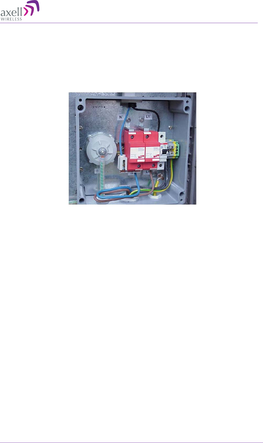
There also need to be a protective device installed on the power supply cord.
Figure 3-24: Protective device installed in connection with the power supply
AXELL MBF -40 AMERICAS REPEATERS
PRODUCT DESCRIPTION AND USER’S MANUAL
38 Doc. No. 00071UM Rev. 3.4 © Axell Wireless Ltd
3.7 Fiber Optic Connection
WARNING!! Maximum input power should not exceed (zero) 0 dBm
NOTE: Clean the Fiber connectors (receptacles and cables) before connecting. See Appendix C –
F/O Cleaning Procedure for details on F/O cleaning procedures.
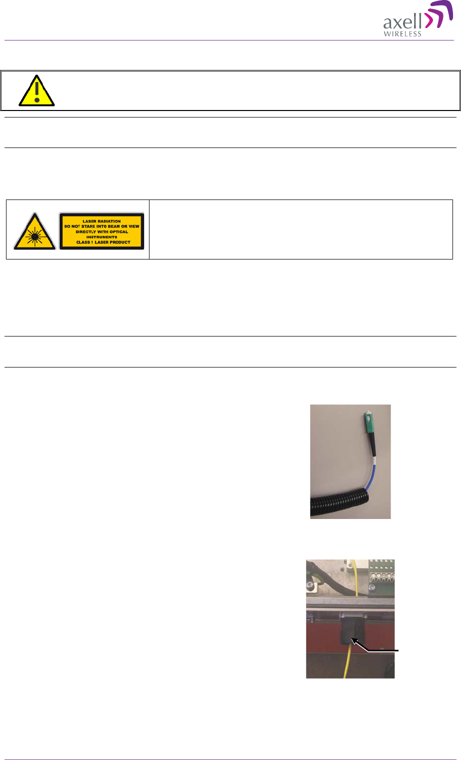
Class 1 Laser
This product is equipped with class 1 lasers, as per definition in EN 60825-1.
Caution!!!
Un-terminated optical receptacles may emit laser
radiation.
Do not stare into beam or view with optical instruments.
Use the following over the complete link between the Repeater and OMU:
• Use angled APC connectors at 8deg angle
• APC type ODF connections
Connecting the Fiber Optic Cable
NOTE: The procedure below includes F/O connection instructions for both single sector and for
MIMO topologies.
1. Select type of optic Fiber (Recommended Fiber cable is single mode 9/125).
2. Run the Fiber through a corrugated
sleeve (not supplied). For MIMO models,
route both Fibers through the same
sleeve.
Figure 3-25: Run Optic Fibers through Sleeve
3. Insert the optic Fiber hose fitter (may be
pre-assembled) and route the Fiber
cable(s) via the Fiber input (see front
panel interfaces in section 1.7.2).
Figure 3-26: Route Optic Fiber(s) via the Fiber
Input
Fiber hose
fitter
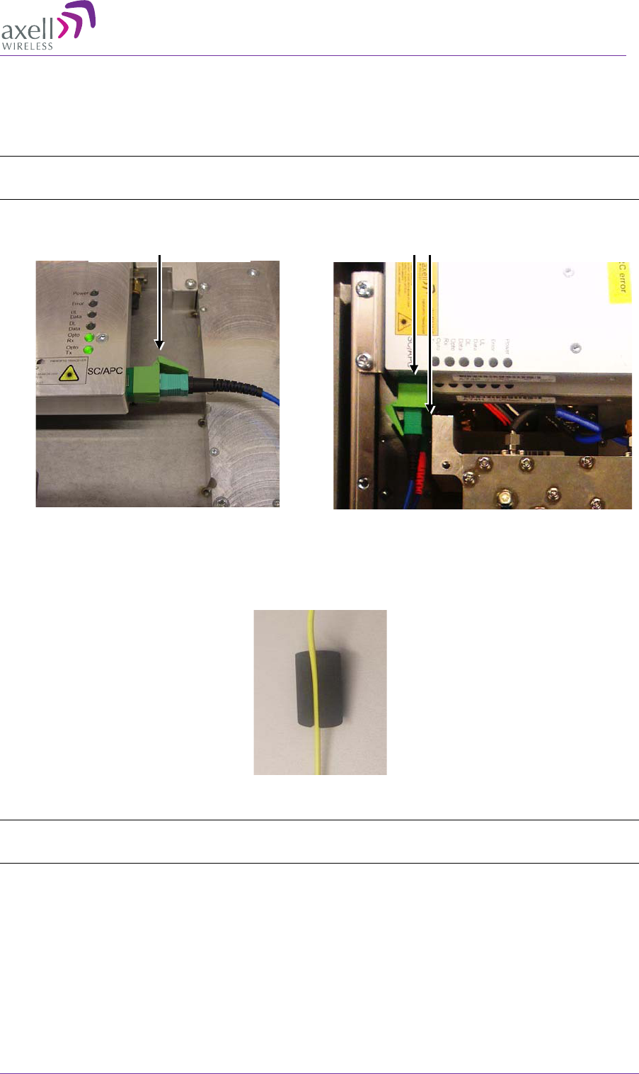
AXELL MBF-40 AMERICAS REPEATER
PRODUCT DESCRIPTION AND USER’S MANUAL
© Axell Wireless Ltd Doc. No. 00071UM Rev. 3.4 39
4. Connect the Fiber(s) to the Fiber Optic Converter(s) inside the repeater:
• Single sector MBF-40 – one optic converter is installed in the repeater.
• MIMO MBF-40 – two optic converters are installed in the repeater (connect
both).
NOTE: Make sure the Fiber is not bent too sharply inside the repeater as to avoid communication
disruptions.
Figure 3-27: Single F/O Connection
Figure 3-28: MIMO Dual F/O Connection
5. Place the Fiber(s) in the rubber seal (for MIMO, run both Fibers in the same rubber
seal).
Figure 3-29: Run Fiber in the Rubber Seal (for MIMO, Run Both Fibers in the Same Rubber Seal)
NOTE: The sleeve (not supplied), together with the rubber seal, meets the protection standard
IP65/NEMA4.
Single F/O Connector
Dual F/O Connectors
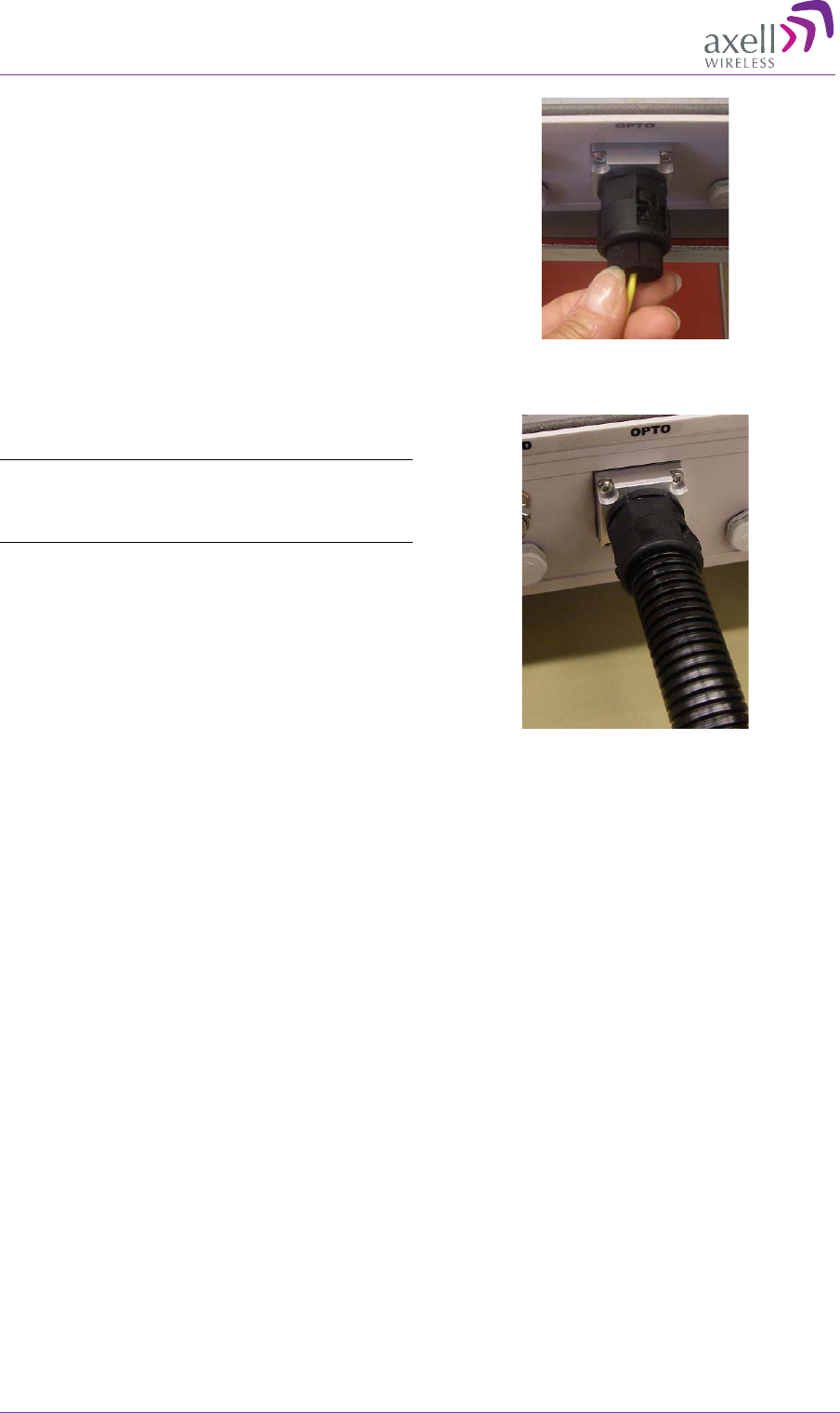
AXELL MBF -40 AMERICAS REPEATERS
PRODUCT DESCRIPTION AND USER’S MANUAL
40 Doc. No. 00071UM Rev. 3.4 © Axell Wireless Ltd
6. Adjust the Fiber(s) length inside the
repeater and insert the seal into the
Fiber inlet.
Figure 3-30: Adjust F/O Length
7. Attach the sleeve to the Fiber optic
inlet. This completes the procedure.
Note: Clean the Fiber connector before
connecting it to the system. See instruction in
Appendix C – F/O Cleaning Procedure.
Figure 3-31: Connect Sleeve
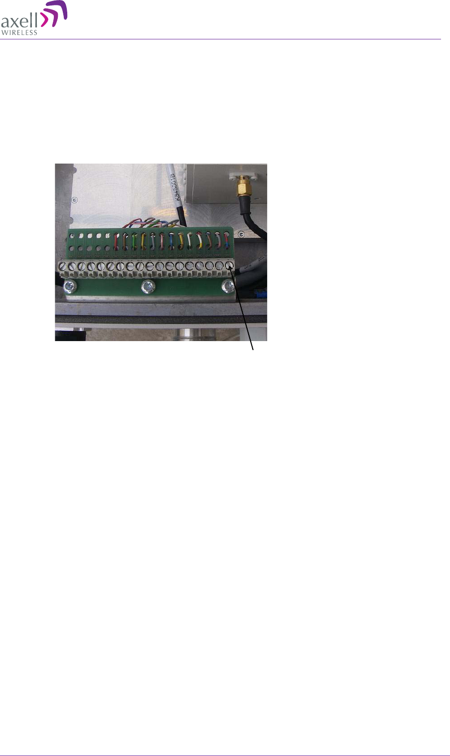
AXELL MBF-40 AMERICAS REPEATER
PRODUCT DESCRIPTION AND USER’S MANUAL
© Axell Wireless Ltd Doc. No. 00071UM Rev. 3.4 41
3.8 External Alarm and Relay Connections
The repeater is equipped with an external alarm interface card. The connector plinth for
the external alarms is located at the bottom of the repeater.
The strain relief fitting in is a Pg 13.5 suitable for a 6-12 mm cable diameter.
Connect the alarm cords to the plinth according to the pin layout below (in the standard
version pins 14 – 18 are not used).
Figure 3-32: External Alarm and Relay Pinout
3.8.1 External Alarm
• Four external alarm sources can be connected to the repeater.
• Alarm operating voltage: between 12 and 24VDC.
• Alarm polarity can be configured:
• Active-low - when there is no voltage the alarm indicator will turn red
• Active-high - an applied voltage of between 12 and 24 V will cause the
external alarm indicator to turn red.
• The repeater can supply +15 VDC to an external alarm source through pin 9 and 10.
The maximum allowed load is 100mA.
3.8.2 Relay
• Relay (pin 11 and 12) can be connected to an external device to indicate an alarm.
• Can be configured to trigger on any number of internal and external alarms. The
maximum current that can be supplied is 100mA.
1External alarm 1A
2External alarm 1B
3External alarm 2A
4External alarm 2B
5External alarm 3A
6External alarm 3B
7External alarm 4A
8External alarm 4B
9Alarm +15V
10 Alarm 0V
11 Relay Output 1A
12 Relay Output 1B
13 GND
14 NC
15 NC
16 NC
17 NC
18 NC
Pin # Signal
Pin 1
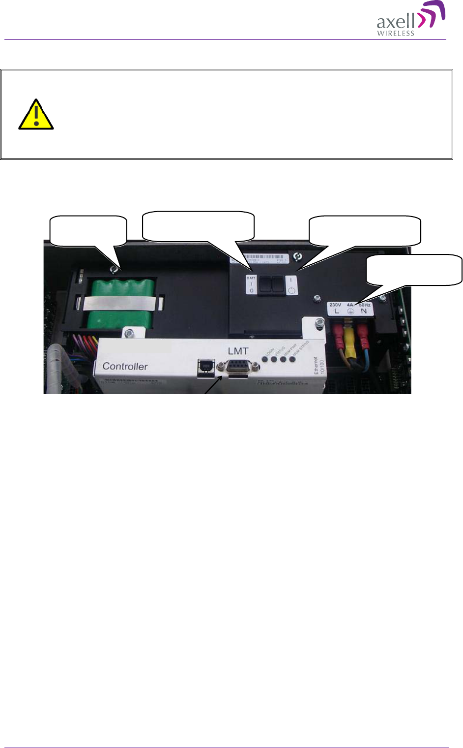
AXELL MBF -40 AMERICAS REPEATERS
PRODUCT DESCRIPTION AND USER’S MANUAL
42 Doc. No. 00071UM Rev. 3.4 © Axell Wireless Ltd
3.9 Power and Backup Battery
CAUTION!!
• Make sure the antenna cables or 50 ohm terminations are connected to
the repeater’s antenna connectors before the repeater is turned on.
• Be sure a CIRCUIT BREAKER meeting the instructions given in this
section is connected near the unit at an easily reachable and accessible
location from the unit.
The image below shows the location of the various power elements. These are described
in detail in the following sections.
Figure 3-33: Power Elements Inside Repeater
3.9.1 Dual Power Supply Models
In dual power supply models, the two power supplies are installed and both are active at
all times. The power supplies are interconnected internally; therefore, a single power
connection activates them bot.
The required power wiring and circuit breaker does not differ from the single power
supply models.
3.9.2 Circuit Breaker
The power connections to the unit are hard-wired. To disconnect the unit (either
manually or automatically in case of overcurrent), it is required to install a circuit
breaker on the wall near the unit, at an easily accessible distance and location from the
unit.
Circuit-breaker minimum requirements
• 10A, 250VAC
• Needs to be SAFETY approved
• Requires minimum contact separation of 3mm.
• Install on the wall near the unit
115/230 VAC
power connections
Power ON/Standby
switch
Backup
battery pack
Battery (BATT)
ON/OFF switch
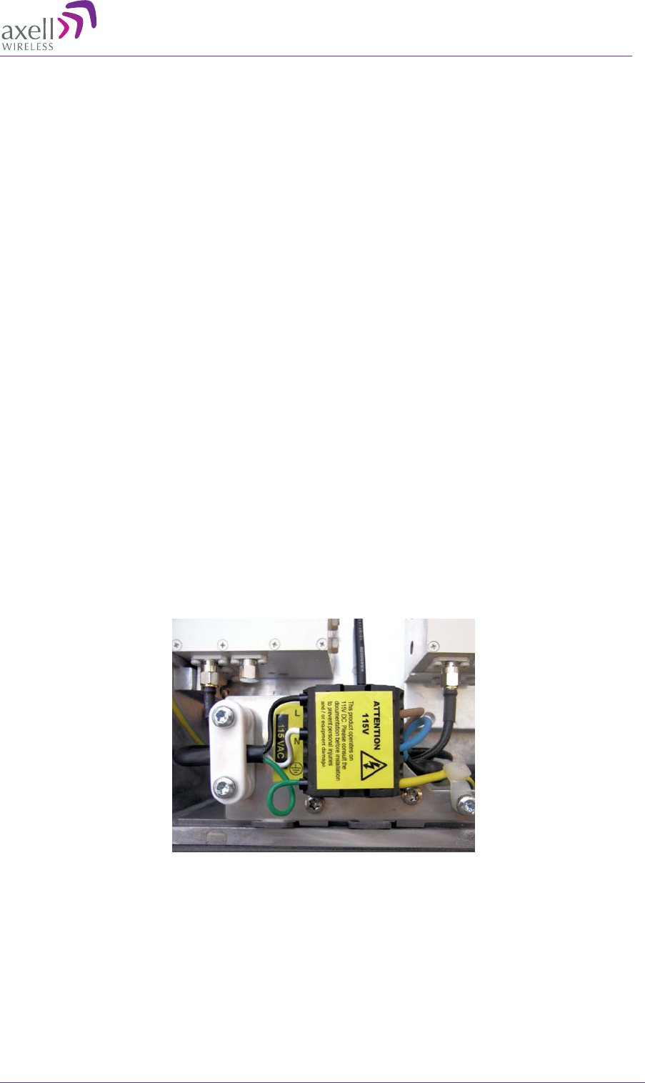
AXELL MBF-40 AMERICAS REPEATER
PRODUCT DESCRIPTION AND USER’S MANUAL
© Axell Wireless Ltd Doc. No. 00071UM Rev. 3.4 43
3.9.3 Connecting the Power Source
• Power Source: 115 VAC 60 Hz or -48 VDC
• The -48VDC version of the power supply is designed to turn off if the supply voltage
falls below -36V (±1V). It will turn on again as the supply voltage reaches -43V (±
1V).
• The power supply has a switch which allows it to be set in “on” position or in “stand
by”.
NOTES the following:
• In the stand by position the repeater is still connected to the power supply
but not operational.
• On repeaters mounted in an extended box with two power supplies, both
power supplies needs to be switched on.
3.9.4 115 VAC Power Source
Cable requirements:
• Cable should be NRTL (safety) approved with a minimum of 14AWG or 2.5mm2 per
conductor, and maximum of 12AWG or 4mm2 per conductor.
• For safety, the GND cable must be 10mm longer than the Phase and Neutral
cables.
Connect the power cable to the plinth as show below:
• Phase linked to the Black cable
• Neutral linked to the White
• Ground to the Green where for SAFETY, the GND cable must be 10mm longer
than the Phase and Neutral cables.
Figure 3-34: 115VAC Power Connections
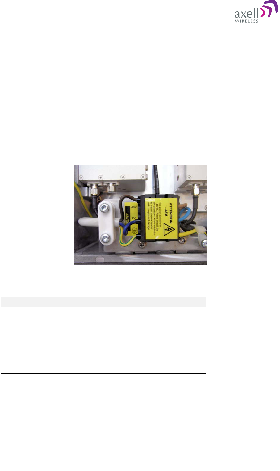
AXELL MBF -40 AMERICAS REPEATERS
PRODUCT DESCRIPTION AND USER’S MANUAL
44 Doc. No. 00071UM Rev. 3.4 © Axell Wireless Ltd
3.9.5 -48V Power Source Connection
Note: The -48VDC version of the power supply is designed to turn off if the supply voltage falls below
-36V (±1V), not to drain the feeding battery. It will turn on again as the supply voltage reaches -43V
(± 1V).
-48V power supply requirements
The 48VDC power supply must comply with SELV requirements, as defined in EN60950,
which implies double isolation. The output power needs to be 48VDC +25%/-15%. The
maximum input current is 8A.
Connect the power cable to the plinth as show below:
• Phase linked to the Brown cable
• Neutral linked to the Blue
• Ground to the Green and Yellow. See illustration below.
Figure 3-35: -48VDC Power Connections
Recommended cable areas for 48VDC
Distance Cable Area
0 -
10 meters between
repeater and power supply 2,5 mm²
10 –
50 meters between
repeater and power supply 4 mm²
Over 50 meters between
repeater and power supply
Recommendation is to
reconfigure the installation, or
to make special arrangements
to increase cable area
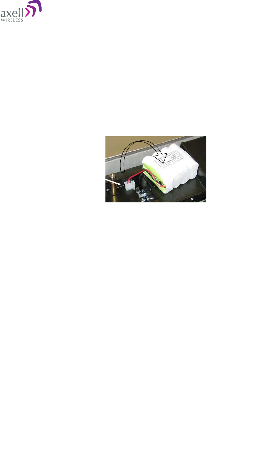
AXELL MBF-40 AMERICAS REPEATER
PRODUCT DESCRIPTION AND USER’S MANUAL
© Axell Wireless Ltd Doc. No. 00071UM Rev. 3.4 45
3.9.6 Backup Battery
• On the Power Supply unit a rechargeable battery pack in mounted. This part also
includes charging and supervision electronics.
• The backup battery will provide the Control Module with enough capacity to send an
alarm in case of input power failure.
• The battery can be switched on and off. The switch is placed adjacent to the main
power switch on the power supply.
• At delivery the back-up battery is connected.
• The battery is replaced by lifting the battery pack out of the crate and disconnecting
the cable.
Figure 3-36: Backup Battery
Connector
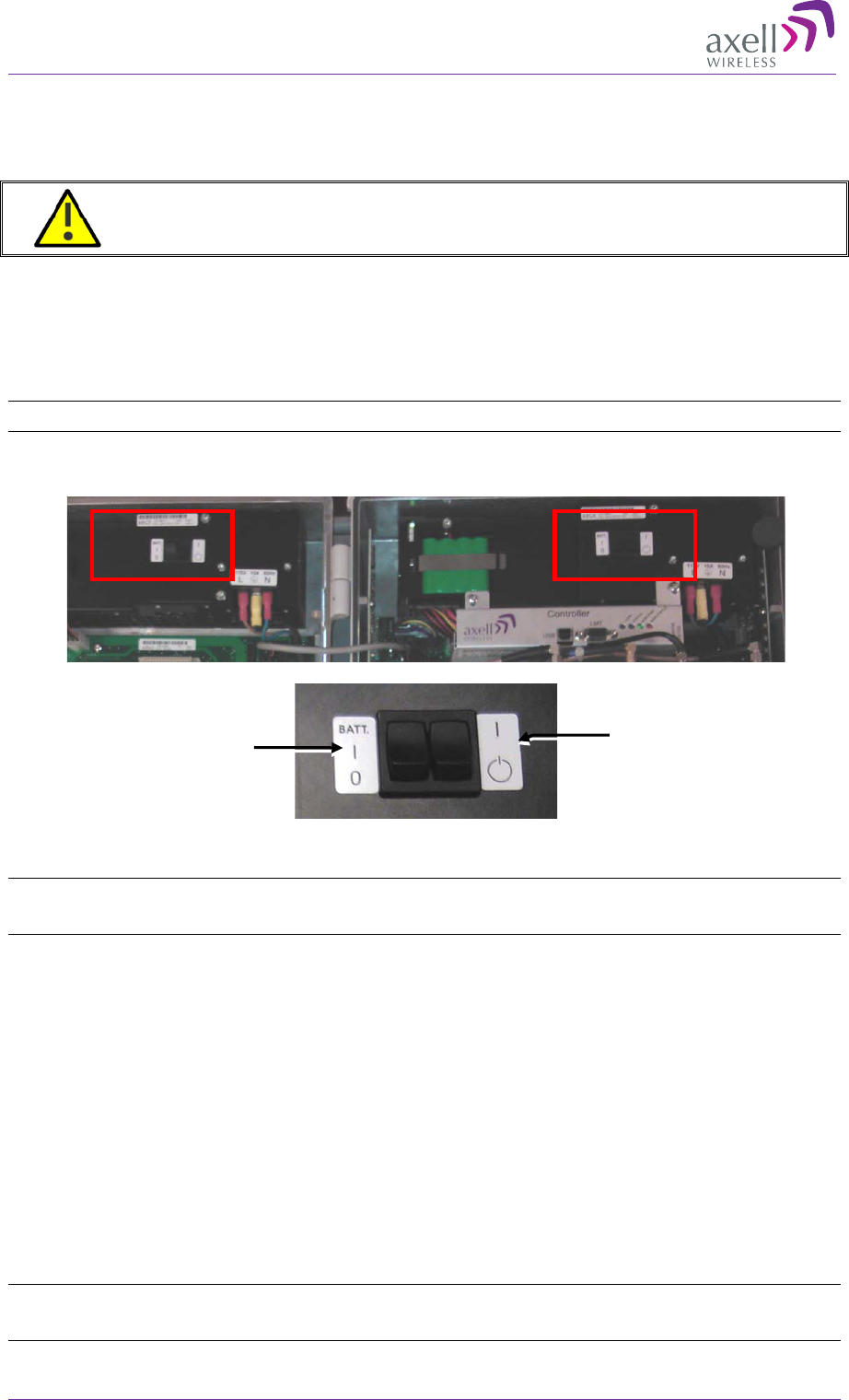
AXELL MBF -40 AMERICAS REPEATERS
PRODUCT DESCRIPTION AND USER’S MANUAL
46 Doc. No. 00071UM Rev. 3.4 © Axell Wireless Ltd
3.10 Power ON
3.10.1 Switching Power ON
CAUTION!! Make sure the antenna cables or 50 ohm terminations are connected to
the repeater’s antenna connectors before the repeater is turned on.
To switch power on
1. Switch on the Main Power Switch.
2. Switch on the Secondary Power Supply (model dependent).
3. Switch on the Battery power.
Note: Both power supplies must be switched ON to power up the unit.
Figure 3-37: MBF-40 Power Module
NOTE: The power switches have two positions: “on” and “stand by”. In the stand by position the
repeater is still connected to the power supply but not operational.
3.10.2 Verifying LEDs
Verify the LEDs from the following modules are indicating correct operation (see section
7.3):
• Control module
• F/O converter(s)
• Power supply module(s)
3.11 Closing and Securing the Repeater
Close lid, tighten the screws and lock repeater. Continue with the following section to
setup the repeater.
NOTE: The two screws must be fully tightened. Failure to do so may affect the IP65 compliancy and
therefore any warranty.
Main Power
Switch
Battery
Switch
Secondary
Power Supply
Main Power
Supply
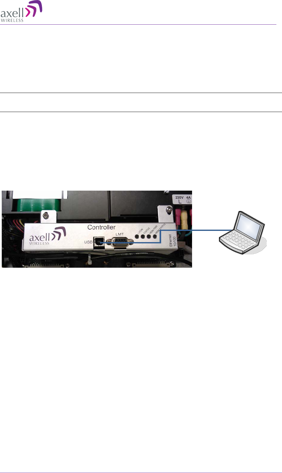
AXELL MBF-40 AMERICAS REPEATER
PRODUCT DESCRIPTION AND USER’S MANUAL
© Axell Wireless Ltd Doc. No. 00071UM Rev. 3.4 47
4 Opening a Session and Navigating GUI
4.1 Opening a Direct Web Session
4.1.1 Connecting Locally
NOTE: This connection requires downloading the USB driver from the provided setup disk (or
connection to the internet, where the driver is automatically loaded).
To open a local session:
1. Open the MBF-40 cover
• Connect to the USB port on the Controller module. If the USB driver is not
already installed on your laptop, the system will search for the driver on the
provided setup disk or on the internet (if a network connection is available).
• Run a browser and login according to the following section.
Figure 4-1: MBF-40 Controller Module Connection
USB
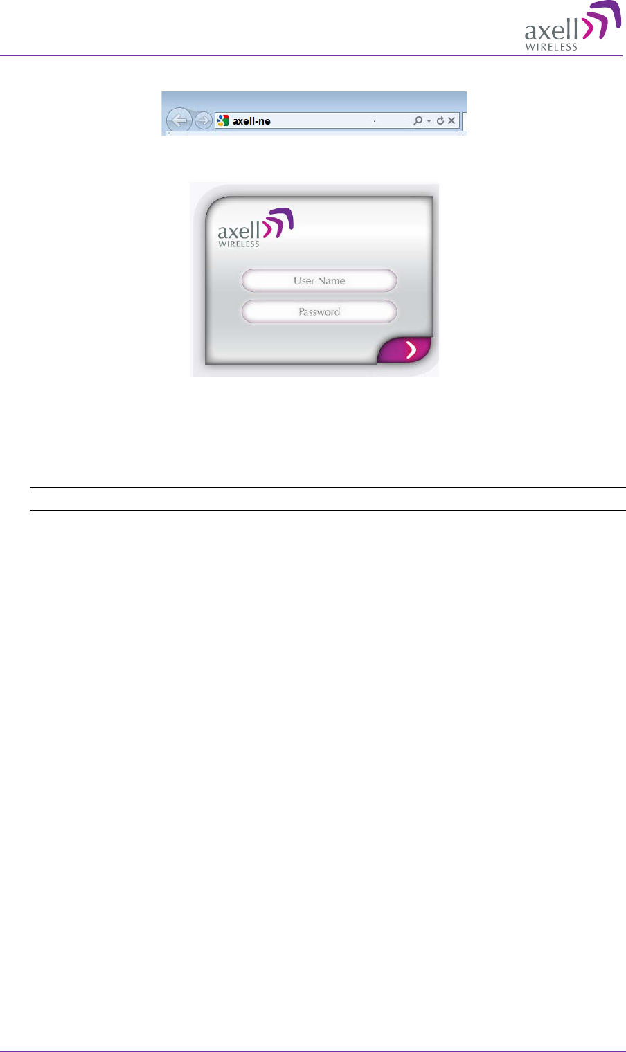
AXELL MBF -40 AMERICAS REPEATERS
PRODUCT DESCRIPTION AND USER’S MANUAL
48 Doc. No. 00071UM Rev. 3.4 © Axell Wireless Ltd
1. Open the web browser and type "axell-ne" in the address bar.
The Axell login dialog appears.
Figure 4-2: Login Screen
2. Use the following username and password to login:
• Username: axell
• Password: AxellPasswd
Note: It is highly recommended to change the default password according to section 6.4.3.
The Web GUI Main Window appears. This is the same window is also viewed via the
OMU II.
4.1.2 Remote Connection and Login
This type of Web session requires connecting the Repeater to the network.
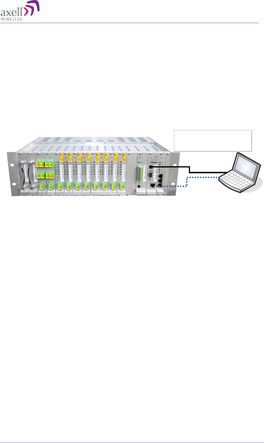
AXELL MBF-40 AMERICAS REPEATER
PRODUCT DESCRIPTION AND USER’S MANUAL
© Axell Wireless Ltd Doc. No. 00071UM Rev. 3.4 49
4.2 Open a Session to the MBF-40 via the OMU II
1. Open a local or remote session to the host OMU II:
• Remote session – open a Browser session in the same subnet as the host
OMU II and enter the IP of the host OMU II (see OMU user manual for
detailed procedure). Enter the OMU II User Name (e.g. axell) and
Password (provided by your system administrator).
• Local session– connect to the OMU II Control Module's USB or Ethernet
ports. Enter the OMU II User Name (e.g. axell) and Password (provided by
your system administrator).
• After accessing an OMU II session, commission the MBF-40 according to the
following section.
Figure 4-3: Connection to OMU II
USB
Ethernet
Connect to EITHER the
USB port OR Ethernet port
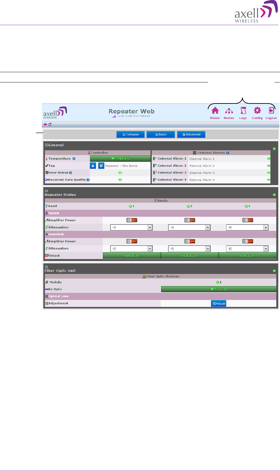
AXELL MBF -40 AMERICAS REPEATERS
PRODUCT DESCRIPTION AND USER’S MANUAL
50 Doc. No. 00071UM Rev. 3.4 © Axell Wireless Ltd
4.3 Navigating the Web Interface
The Web GUI window provides access to the management options of the MBF-40.
Several tabs (and sub-tabs) are available: Home, Nodes, Logs, etc., while the Home tab
(illustrated below), is displayed on login.
NOTE: for 5-Band MBF-40 home screen, see Figure 4-5.
Figure 4-4: MBF-40 Home Screen
Menu options buttons
Home
screen
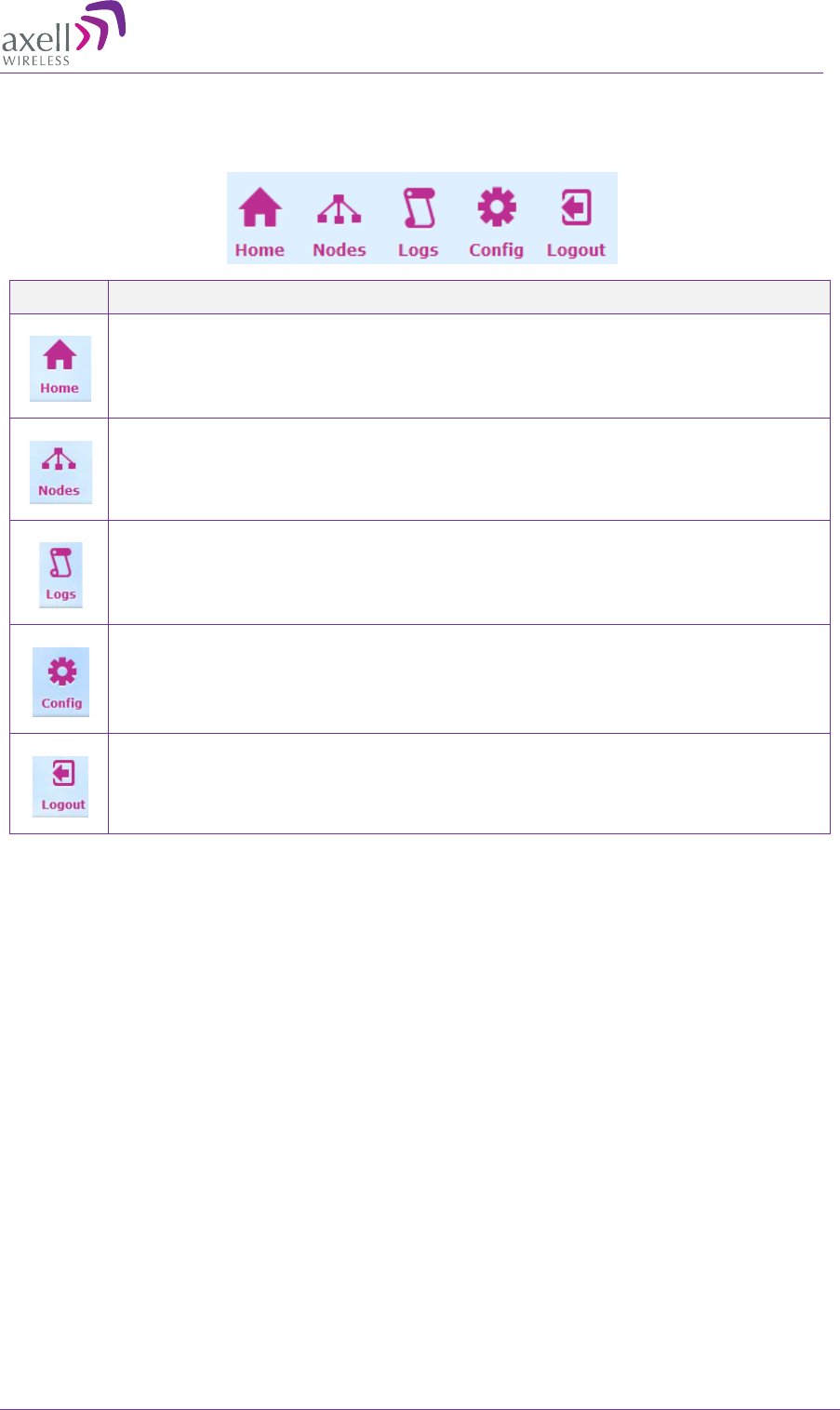
AXELL MBF-40 AMERICAS REPEATER
PRODUCT DESCRIPTION AND USER’S MANUAL
© Axell Wireless Ltd Doc. No. 00071UM Rev. 3.4 51
4.3.1 Management Options Buttons
The following table briefly describes the main functions of each tab:
Tab Description
Provides a general status and alarm information. Switching to Advanced
View will toggle a more detailed view of each band and module. Section
4.3.2.
Lists the remote nodes –
corresponding OMU and units connected the
specific OMU.
List of recent operations. Section 7.2.
Provides a range of MBF-
40 configuration procedures such as
communication, RF, Date and Time, Password, etc. Section 6.1.
Logout of the system.
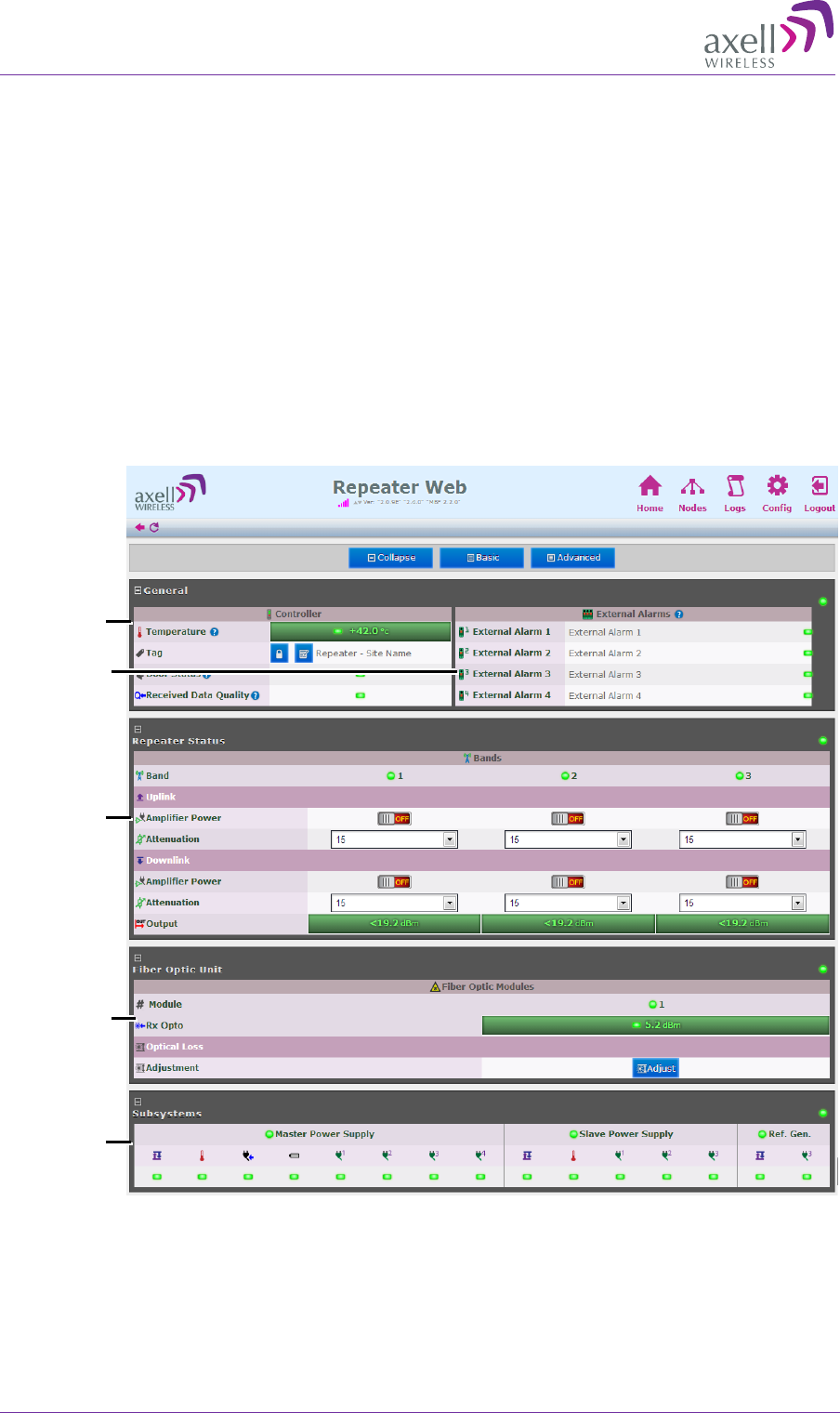
AXELL MBF -40 AMERICAS REPEATERS
PRODUCT DESCRIPTION AND USER’S MANUAL
52 Doc. No. 00071UM Rev. 3.4 © Axell Wireless Ltd
4.3.2 Home Screen Overview
The screen is divided into four basic areas:
• Controller – shows general information on the MBF-40 device such as identification
and temperature level.
• External Alarms – shows status of external alarms and the defined names.
• Repeater Status – RF connection status is divided into two sections:
• Band – shows general band status and band name (e.g. 800MHz GSM).
• Uplink/Downlink – gain, attenuation and connection status in the specific
direction.
• Fiber Optic Unit – shows status on connection to remote OMU and allows for optical
link adjustment.
• Sub-systems – overall status of all sub-systems such as power supplies, battery,
communication etc.
General
External
Alarms
UL and DL
output
control
options
Fiber
Optic
options
Power
monitoring
options
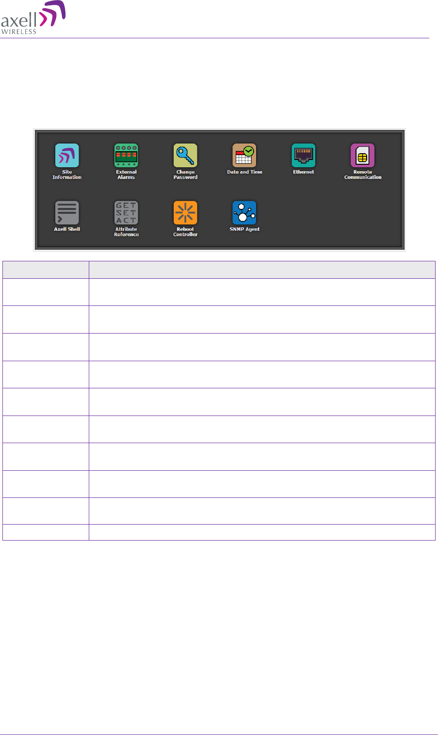
AXELL MBF-40 AMERICAS REPEATER
PRODUCT DESCRIPTION AND USER’S MANUAL
© Axell Wireless Ltd Doc. No. 00071UM Rev. 3.4 53
4.3.3 Configuration Screen Overview
The configuration screen provides access to the MBF-40 configuration options.
To access the configuration screen
Click on the Config menu option in the Main window. The following screen appears.
Option Description
Site
Information Configure and display MBF-
40 identification information. See section
6.1.1
External
Alarms Used to activate and assign names to external alarms. See section
6.1.3
Change
password Used to update system login password for the logged-in user. See
section 6.4.3
Date and Time Used to configure the time stamp for dating MBF-40 events. See
section 6.1.2.
Ethernet Used to define the IP Address for remote access via Ethernet. See
section 6.1.4
Remote
Communication Used to configure remote communication parameters and AEM
integration. See section 6.2
Axell Shell Command line used to communicate with the remote units. List of
commands is found under Help. See section 6.6
Attribute
Reference CLI commands and attributes directory. See section 6.7
Reboot
controller Soft restarts the MBF-40 device. See section 6.5.
SNMP Agent SNMP Agent configuration. See section 6.3
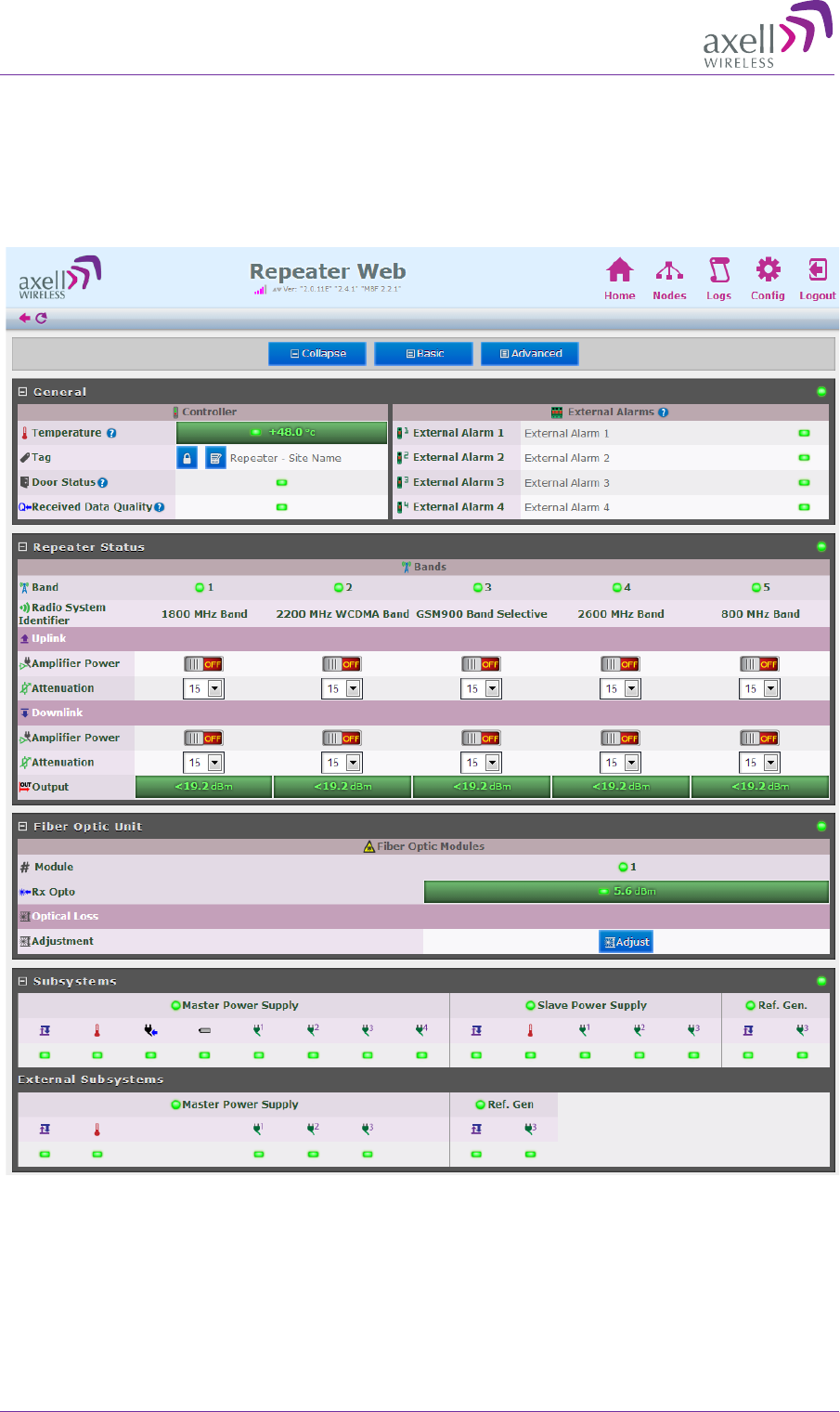
AXELL MBF -40 AMERICAS REPEATERS
PRODUCT DESCRIPTION AND USER’S MANUAL
54 Doc. No. 00071UM Rev. 3.4 © Axell Wireless Ltd
4.3.4 Five Service System GUI
The five service system GUI has no significant differences with other GUIs. It is
displayed as one 5-band unit with same configurations and options.
The Home screen displays all the 5 bands in a time (same as in a tri-band/ quad-band),
as shown in Figure 4-5.
Figure 4-5: 5-Band MBF-40 Home Screen

AXELL MBF-40 AMERICAS REPEATER
PRODUCT DESCRIPTION AND USER’S MANUAL
© Axell Wireless Ltd Doc. No. 00071UM Rev. 3.4 55
Figure 4-6: 5-Band MBF-40 Site Information
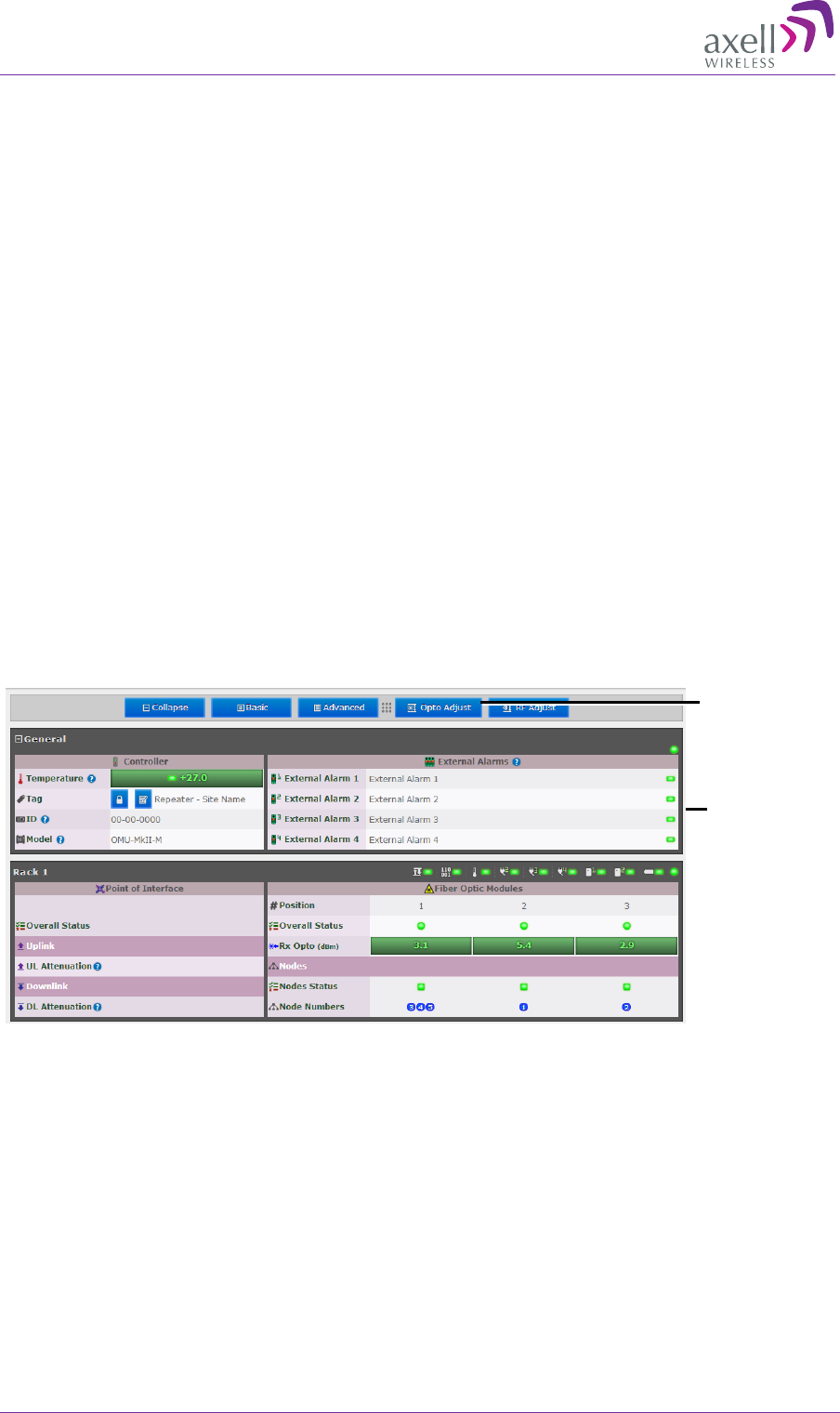
AXELL MBF -40 AMERICAS REPEATERS
PRODUCT DESCRIPTION AND USER’S MANUAL
56 Doc. No. 00071UM Rev. 3.4 © Axell Wireless Ltd
5 MBF-40 Commissioning
After the repeater is connected, it is identified by the OMU II via the Fiber connection
and the unit is commissioned from the OMU II. The commissioning process consists of a
few simple steps.
MBF-40 Setup and Commissioning consists of the following
1. Opening an OMU II session – for accessing the MBF-40 configuration window (via
OMU II)
2. Performing Optical Loss Adjustment on the connected MBF-40
3. Setting the required RF attenuation and gain levels on the remote MBF-40
4. Assigning the unit a recognizable name (according to its location)
5.1 MBF-40 Optical Loss Adjustment (OLA)
MBF-40 OLA is performed from the OMU II.
For MBF-40 remotes, the maximum compensation is increased to 26dB to support
shorter Fiber optic distances.
To perform MBF-40 OLA (via OMU II)
1. From the OMU II main window, click the Opto Adjust button.
Figure 5-1: OMU II Main window
Click to access
OLA screen
OMUII Main
window
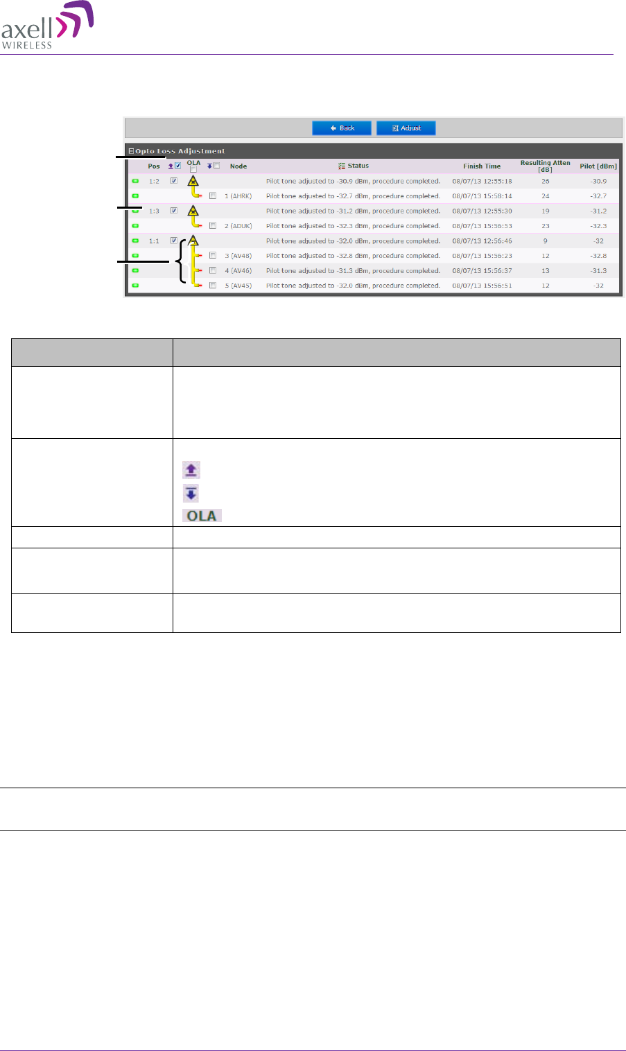
AXELL MBF-40 AMERICAS REPEATER
PRODUCT DESCRIPTION AND USER’S MANUAL
© Axell Wireless Ltd Doc. No. 00071UM Rev. 3.4 57
The OLA screen appears. The screen lists the OLA options (and status) for each link.
(The links are listed according to the OMU II slot to which the remote is connected.).
Figure 5-2. Configure and Initiate Optical Loss Adjustment
Column Description
Pos
Each Rack corresponds to an OMU unit whereas each Slot
corresponds to an Opto-
Module. Slots are numbered
according to their position in the OMU Chassis (numbered left
to right).
Select All Batch selection options:
- mark all remotes for UL opto-adjustment.
- mark all remotes for DL opto-adjustment.
- mark all remotes for DL and UL adjustment.
Node Node list number and identification (e.g. AHFK)
Status Displays an Error if process failed. If successful the pilot tone
used and the adjustment level will be displayed.
Resulting
Attenuation Compensation level used for the opto-module (in dB).
3. Mark the check-boxes corresponding to the remotes (each connected to the
designated Opto-module/Opto-Splitter) to which to perform the adjustment.
4. OLA (DL/UL) may be performed on each node individually (or a batch) or on all
nodes at once by marking the checkbox next to the desired corresponding Opto-
module and clicking Adjust.
To easily mark all checkboxes mark the checkbox named OLA.
NOTE: The process may take several minutes depending on the size of the system and remote
distance.
Rack#:Opto-
Module
Select nodes
for UL/DL
Adjustment
F-DAS
Remotes via
Optic Splitter
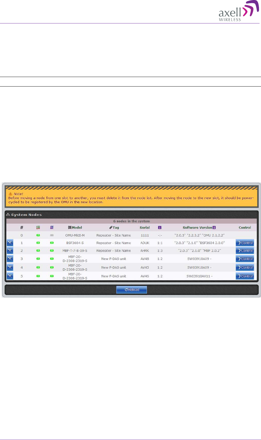
AXELL MBF -40 AMERICAS REPEATERS
PRODUCT DESCRIPTION AND USER’S MANUAL
58 Doc. No. 00071UM Rev. 3.4 © Axell Wireless Ltd
5.2 RF Balancing
The MBF-40 RF Balancing procedure can be performed manually (the automatic option
specified in section 5.2.2 will be available in the future) via the OMU II web interface.
5.2.1 Manual RF Balancing
NOTE: If connected locally, enter the MBF-40 Home screen and skip to step 2.
The manual balancing procedure consists of the following steps:
• Verifying the DL RF output level is maximized by setting the required DL attenuation
of the signal.
• Setting the UL attenuation according to the DL.
• In case of noise, adjusting the UL attenuation to reduce noise
To balance the MBF-40 UL and DL outputs
1. Access the MBF-40 Configuration window:
• Click on the Nodes button. The below pane appears
• Click Control next to the node to be balanced.
2. The resulting pane can be displayed in two views:
• Basic – default view (Basic button)
• Advanced – provides more information (Advanced button)
The dialog below shows an example of the Basic (default) view.
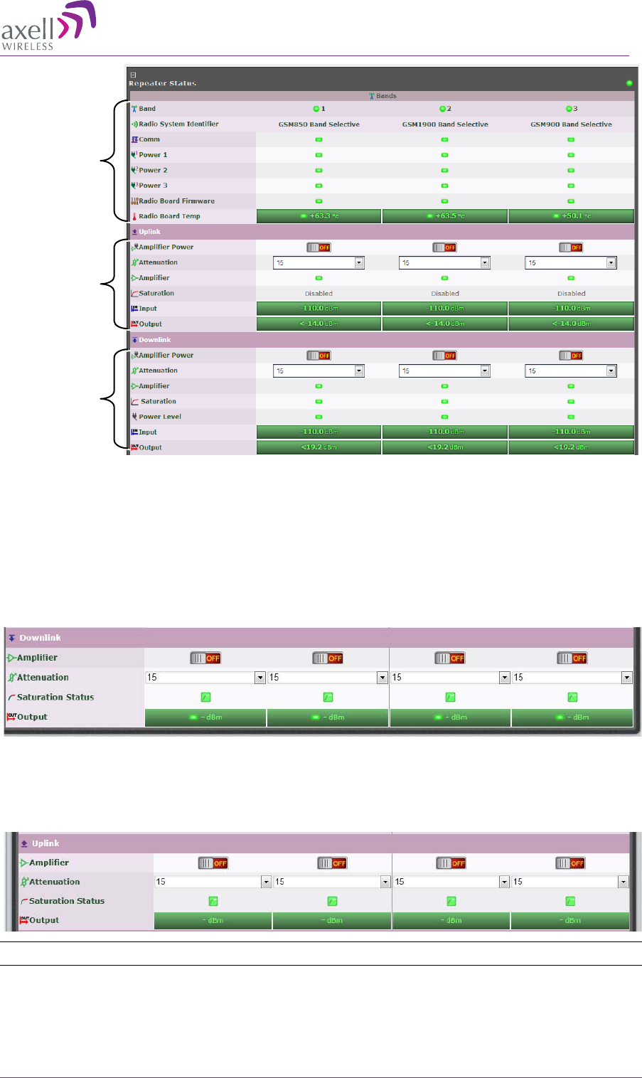
AXELL MBF-40 AMERICAS REPEATER
PRODUCT DESCRIPTION AND USER’S MANUAL
© Axell Wireless Ltd Doc. No. 00071UM Rev. 3.4 59
Figure 5-3: Example of MBF-40 Tri-Band Configuration window
3. In the Downlink:
• Verify the Amplifier for each band is ON.
• Set Attenuation to maximum value (15dB).
• Lower the Attenuation level step by step until the desired Output power
level is reached (Zero attenuation = maximum gain).
• Verify the Amplifier Saturation is GREEN.
4. In the Uplink:
• Verify the Amplifier for each band is ON.
• Set Attenuation equal to the value set in the DL (above).
• Verify the Amplifier Saturation is GREEN.
NOTE: If noise is detected on the link, reduce only the Uplink for optimal signal.
Band
information
UL setting
DL setting
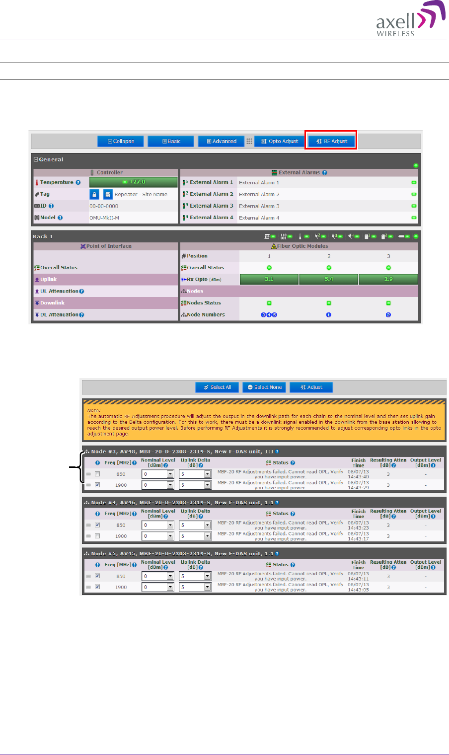
AXELL MBF -40 AMERICAS REPEATERS
PRODUCT DESCRIPTION AND USER’S MANUAL
60 Doc. No. 00071UM Rev. 3.4 © Axell Wireless Ltd
5.2.2 Automatic MBF-40 RF Balancing
NOTE: This feature will be available in future release.
To access the Automatic RF Adjustment pane
1. Access the OMU II Home window and click on RF Adjustment.
Figure 5-4: OMU II Main window
2. The following pane appears.
3. Select the bands of each remote to be adjusted (e.g. 1900MHz band on Node #3)
4. Adjust the following for each band:
• Nominal Level (dBm)
• Uplink Delta (dB)
5. Click Adjust. The procedure may take several minutes depending on the number of
units selected.
Remote with
selected bands
to adjust

AXELL MBF-40 AMERICAS REPEATER
PRODUCT DESCRIPTION AND USER’S MANUAL
© Axell Wireless Ltd Doc. No. 00071UM Rev. 3.4 61
5.3 Integration into the AEM
NOTE: Integration into the AEM is only performed from the AEM side – no action is required from the
MBF-40 side.
The AEM automatically connects to the repeater, downloads all the repeater parameters
and statuses into a database. When all parameters have been downloaded, the AEM
configures the repeater with the IP address where alarms and reports should be sent to,
and optionally with a secondary IP address where the repeater can connect to in case
connection to primary IP fails.
When heartbeat reports and alarms are sent from the repeater to the AEM also the
latest information about the status and RF-configuration is included. This means that the
AEM operator always has information about the current status in the AEM database (and
does not need to call the repeater to find this out).
NOTE: Once the repeater is integrated to the AEM, all changes to the repeater should preferably be
done from the Axell Element Manager in order to ensure that the database always contains correct
information.
5.4 What Next?
The MBF-40 unit is now ready for operation. You may monitor the unit's general status
via the OMU II Main window and if the node is faulty (red LED), access the dedicated
configuration screen in Basic or Advanced view for more information.
NOTE: Consult the OMU II User Manual for additional information on RF and Optical adjustments.
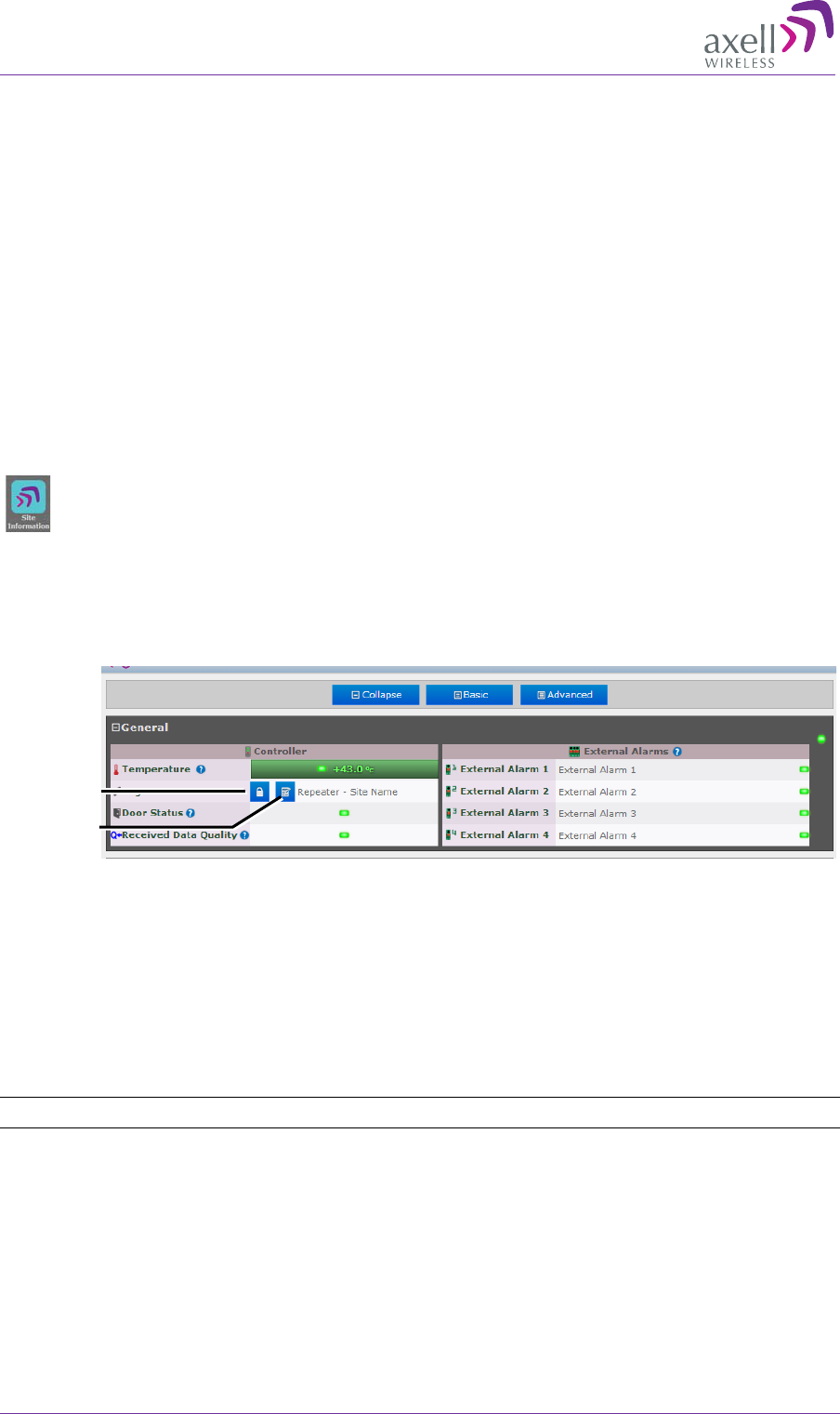
AXELL MBF -40 AMERICAS REPEATERS
PRODUCT DESCRIPTION AND USER’S MANUAL
62 Doc. No. 00071UM Rev. 3.4 © Axell Wireless Ltd
6 MBF-40 Full GUI Description
This chapter provides a detailed description of the complete MBF-40 specific Web GUI
accessible when opening a direct session to the MBF-40.
When an indirect session (via OMU II) is opened to the MBF-40, only the MBF-40 Main
window is available. Additional options are available when a direct session is opened to
the MBF-40 (not via OMU II).
This chapter describes how to open local and remote indirect sessions to the Remote
and the available options when such a session is opened.
6.1 Configuring General Parameters
6.1.1 Site Information – MBF-40 Identification
It is recommended to assign each MBF-40 a recognizable name that will identify
the location, site name, etc. The Site Information button provides access to MBF-40
hardware and software version information.
To set MBF-40 TAG
1. In the Home window, click the edit button next to Tag.
Figure 6-1. Set MBF-40 TAG Name
2. Enter the Name (up to 30 characters), click OK and click Apply.
To view MBF-40 Site Information
Click the Config button and click on the Site Information icon. Two areas are
displayed:
• Control Module – provides hardware and software version information.
• Site Information – provides MBF-40 identification information.
NOTE: for 5-band MBF-40 Site Information, see Figure 4-6.
Edit Tag
Lock Name
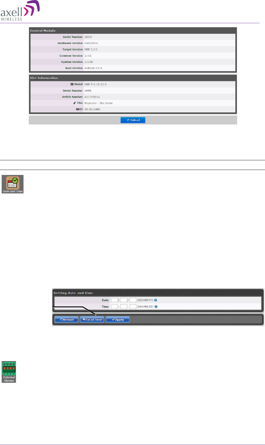
AXELL MBF-40 AMERICAS REPEATER
PRODUCT DESCRIPTION AND USER’S MANUAL
© Axell Wireless Ltd Doc. No. 00071UM Rev. 3.4 63
Figure 6-2. MBF-40 Site Information
6.1.2 Date & Time
NOTE: The date and time are automatically set from the OMU II.
Be sure to set the correct date and time in order to accurately timestamp all
events occurring on the MBF-40.
To set the Date & Time:
1. Click the Config button.
2. Click on Date & Time.
3. Do one of the following:
• Either, enter the correct date and time according to the displayed formats.
• Or, click on Local Time to set the time according to the PC running the
Web-GUI.
4. Click Apply.
Figure 6-3. Configure Date and Time
6.1.3 Configure External Alarms
It is required to configure any connected external alarms according to the trigger
(high or low) and it is recommended to assign the alarms recognizable names (such as
Door Open, High Temperature, etc.)
To configure the external alarms
1. In the Main menu, click the Config button.
2. Click on the External Alarms icon.
Set to local time
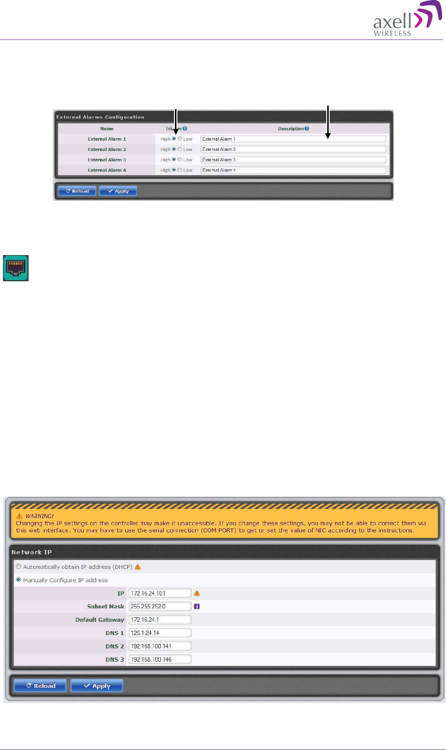
AXELL MBF -40 AMERICAS REPEATERS
PRODUCT DESCRIPTION AND USER’S MANUAL
64 Doc. No. 00071UM Rev. 3.4 © Axell Wireless Ltd
3. For each alarm:
• Set the Trigger as High or Low as required.
• Assign the alarm a recognizable description
4. Click Apply.
Figure 6-4: Configure External Alarms
6.1.4 IP Address
This procedure describes how to set up the IP address either manually or
configure for acquisition via DHCP (usually configured for local management options).
To configure the IP address
1. In the Main menu, click the Config button.
2. Click on Ethernet.
3. For manual IP address configuration:
• Select Manually Configure IP Address.
• Set the IP, Subnet Mask, Default Gateway and DNS addresses.
• Click Apply.
4. For DHCP IP address configuration:
• Select Automatically Obtain IP Address (DHCP).
• No other settings are required.
• Click Apply.
The Manual configuration settings are illustrated below.
Figure 6-5: Configure Local Network Parameters
Enter Alarm
Description
Set High/Low
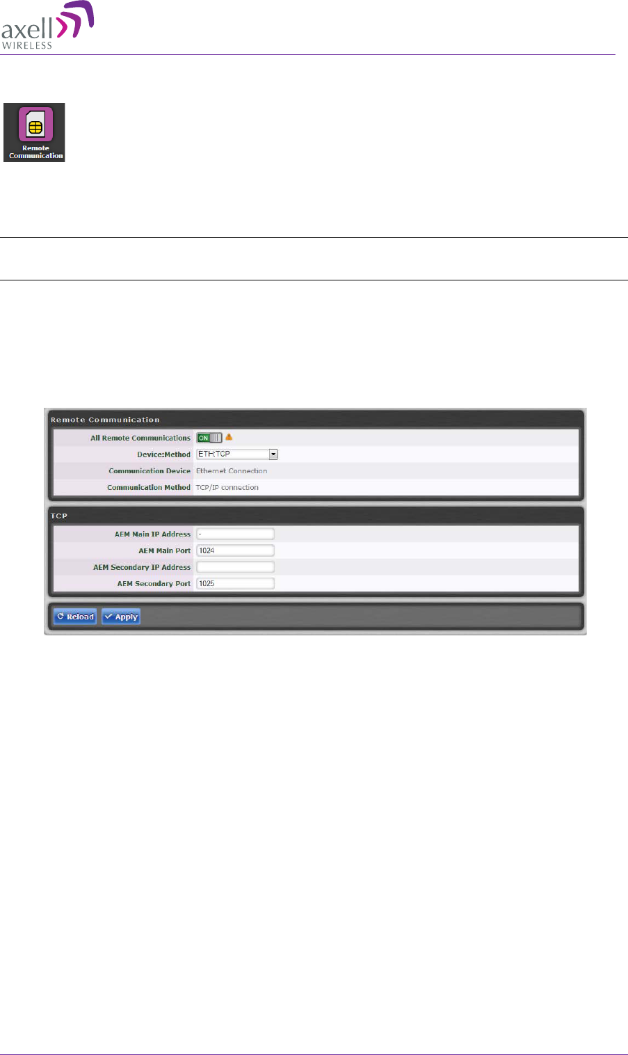
AXELL MBF-40 AMERICAS REPEATER
PRODUCT DESCRIPTION AND USER’S MANUAL
© Axell Wireless Ltd Doc. No. 00071UM Rev. 3.4 65
6.2 Remote Communication Setup
This section describes the Ethernet and SNMP setup. The SNMP setup option
also available in this dialog is described in section 6.3. SNMP .
Select an option (ETH:TCP or ETH:SNMP) and configure. Then select the next relevant
option.
NOTE: The configuration of each option is saved and active. It is not relevant which option is
currently selected (ETH:TCP or ETH:SNMP).
6.2.1 TCP/IP and Ethernet
1. Click on the Config button.
2. From Device:Method select ETH:TCP (Ethernet:TCP/IP).
3. Click Apply.
Figure 6-6: Remote ETH Configuration
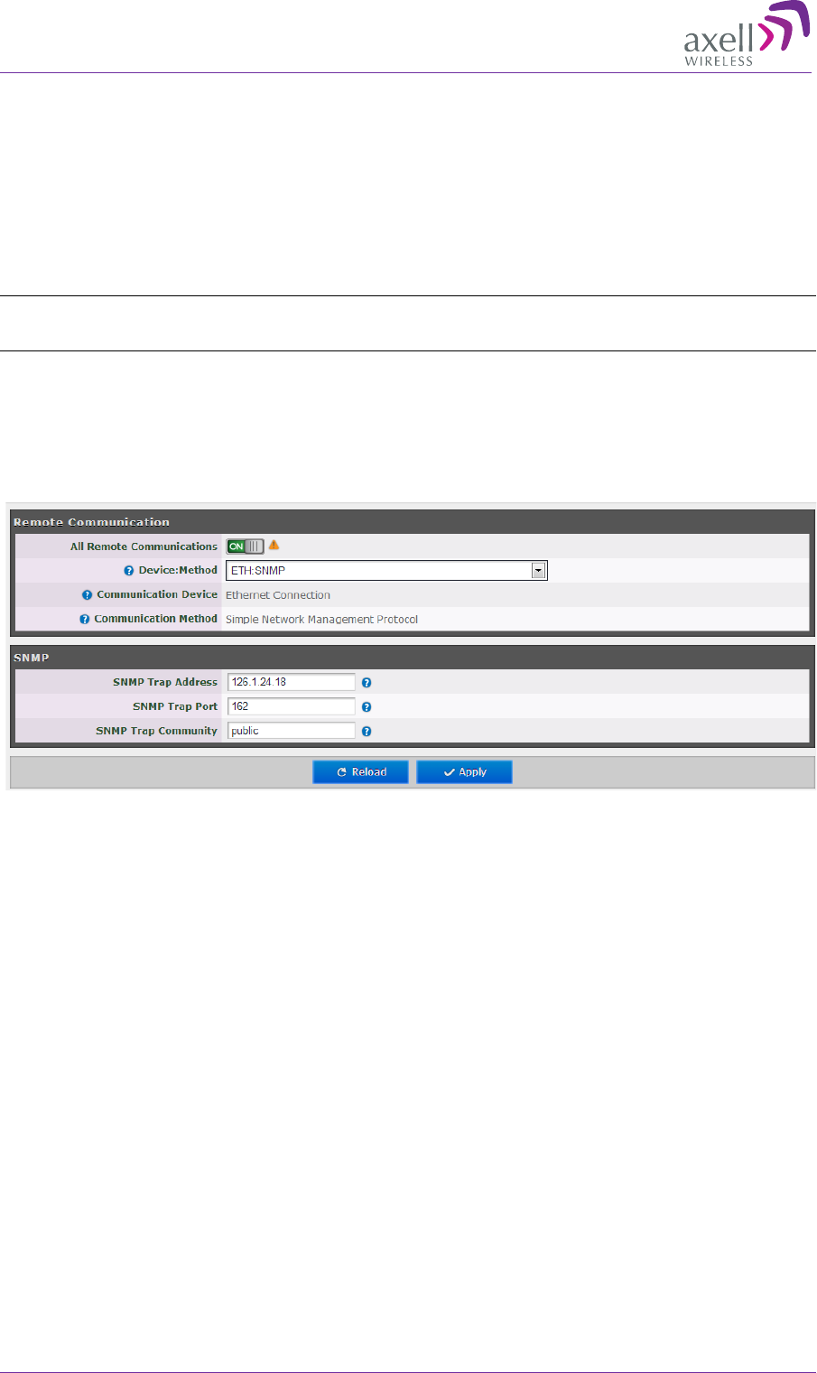
AXELL MBF -40 AMERICAS REPEATERS
PRODUCT DESCRIPTION AND USER’S MANUAL
66 Doc. No. 00071UM Rev. 3.4 © Axell Wireless Ltd
6.3 SNMP Support
The MBF-40 includes SNMP support, including an SNMP Agent and SNMP traps (alarms).
All SNMP queries and traps are supported either via the OMU II or a direct connection to
the unit.
6.3.1 SNMP Traps Parameters
The MBF-40 sends SNMP traps to user defined destination addresses.
NOTE: One destination address can currently be defined via the Web. Seven more destination
addresses can be defined via the Axell Shell.
To configure the SNMP traps destination address
1. Click on the Configure button (top right corner).
2. Select Remote Communication.
3. In the Device:Method field, select ETH:SNMP
4. Define the SNMP trap destination IP address (additional addresses can be defined via
the Axell Shell.).
5. Enter the (destination address device) Trap Port and its Community parameters.
6. Click Apply.
6.3.2 SNMP Agent - Activating and Configuring
The SNMP agent provides inventory management for hosted repeaters (on which the
SNMP agent is enabled) and a table of active alarms in the controller or Fiber system for
remote querying.
The SNMP Agent is responsible for responding to queries and carries out requests. The
SNMP Agent also provides the proprietary Axell MIB (AXELL-AM-MIB), accessible via any
SNMP manager (e.g. HP OpenView).
All SNMP queries to the remote are implemented via an OMU session.
To allow SNMP agent queries
• To allow SNMP queries of the OMU II – the SNMP agent must be enabled on the OMU
II.
• To allow SNMP queries of the remote devices via OMU II – the SNMP agent must be
enabled on the OMU II and on the remote devices.
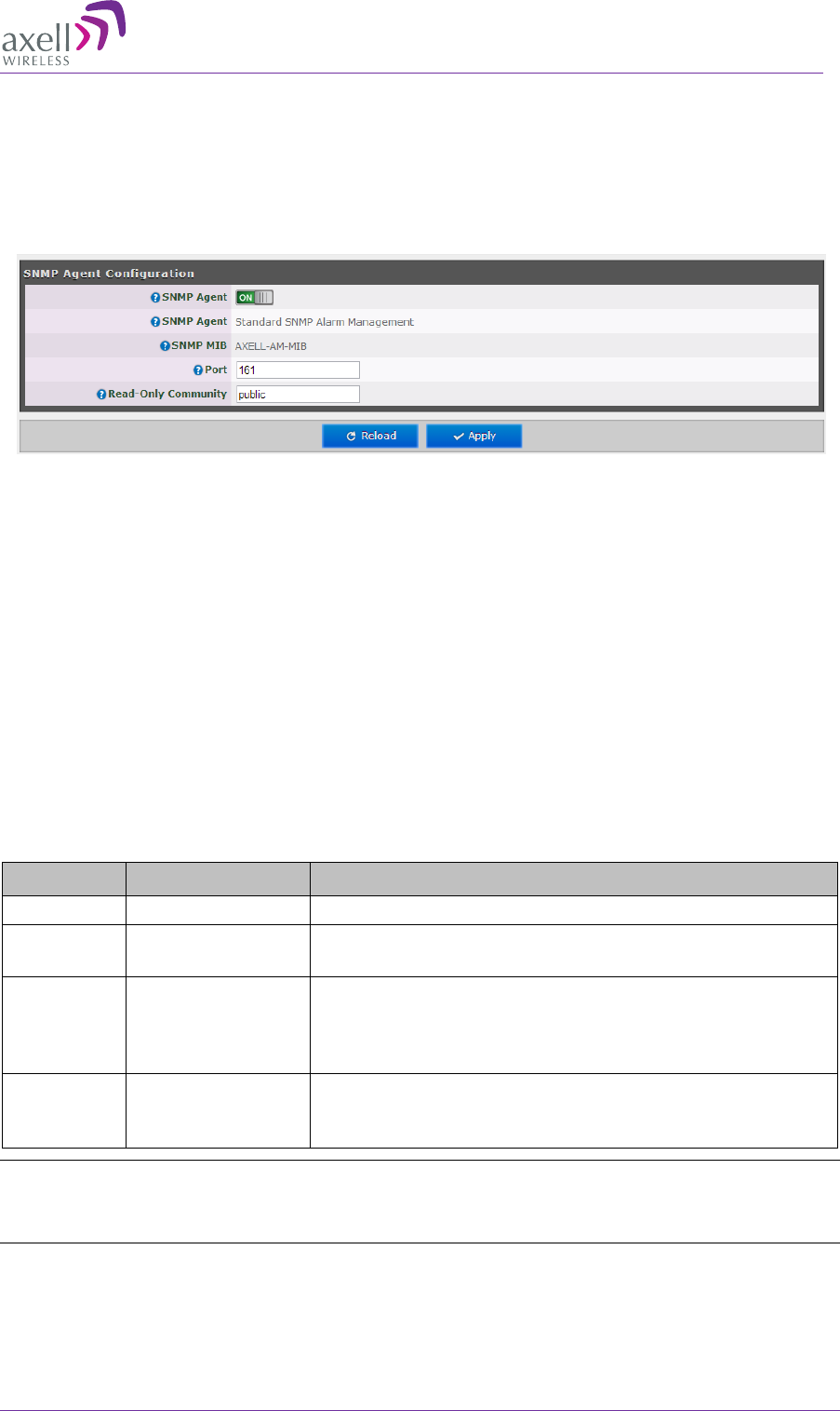
AXELL MBF-40 AMERICAS REPEATER
PRODUCT DESCRIPTION AND USER’S MANUAL
© Axell Wireless Ltd Doc. No. 00071UM Rev. 3.4 67
• Remote units configured with an IP address and connected to the communication
infrastructure, can be queried directly.
To activate the MBF-40 SNMP Agent
1. Click on the Config button (top right corner) and select SNMP Agent Config. The
following pane appears:
2. Set the SNMP Agent toggle to ON.
3. Set the port and the Read-Only community.
4. Click Apply.
6.4 User Accounts
The MBF-40 comes pre-configured with default usernames and passwords in the various
administration levels.
At the moment, updating user accounts is available only via Command Line Interface
(CLI) or Axell Shell. See the Common Commands and Attributes v2.4.0 document for
detailed commands and syntax or click on the Help button at the top right of the Web-
GUI screen.
6.4.1 Default User Accounts
User Name Default Password Details
Axell
AxellPasswd
Default user name.
omcuname iwnkhoob Axell Element Manager (AEM) user account. This
account will not generate VLI, LGO or CLR alarms.
sysadmin AxellAdmin4050 This is the system administration password which is
used for firmware upgrades and user administration.
Escalation to this level is achieved by issuing
command SYSADMIN from the user prompt.
useradmin UseradminPwd23 This account contains user administration privileges.
Escalation to this level is achieved by issuing
command USERADMIN from the user prompt.
NOTE: It is strongly recommended to change the default user names and passwords immediately at
commissioning. This is done by using the command ACT PASSWORD. Please refer to the User
Administration section in Common Commands and Attributes document for detailed syntax.
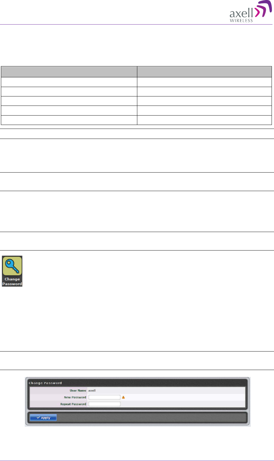
AXELL MBF -40 AMERICAS REPEATERS
PRODUCT DESCRIPTION AND USER’S MANUAL
68 Doc. No. 00071UM Rev. 3.4 © Axell Wireless Ltd
6.4.2 User Access Levels
In this generation of the system, standard users can be promoted to login via the Web
Interface, inheriting the Read-Write or Read-Only access to this interface.
There are five different access levels:
Access Level Default User Levels
Read-Only axell, omcuname, useradmin, sysadmin
Read-Write axell, omcuname, useradmin, sysadmin
Web axell
User Administrator omcuname, useradmin, sysadmin
System Administrator omcuname, sysadmin
Note: New users added to the system have read-only access.
Users may be promoted to read-write and/or web access using the ACT
USERPROMOTE command. See Common Commands and Attributes document for
details on promoting users.
Note: Users omcuname, sysadmin and useradmin cannot be promoted to Web Access due to
security reasons.
6.4.3 Change Password
To prevent unauthorized access, it is highly recommended to change the default
password of the user.
NOTE: Note that you can only change the password for the User Name with which the session was
accessed.
To change the Password
1. In the Main menu, click the Config button.
2. Click the Change Password button.
3. For the current User Name (e.g. axell):
• Enter the New password.
• Repeat the entry.
4. Click Apply.
NOTE: The password is not encrypted during transmission. Use this screen only if the connection to
the repeater is safe. Use the CLI commands using an encrypted connection, if possible (i.e. SSH).
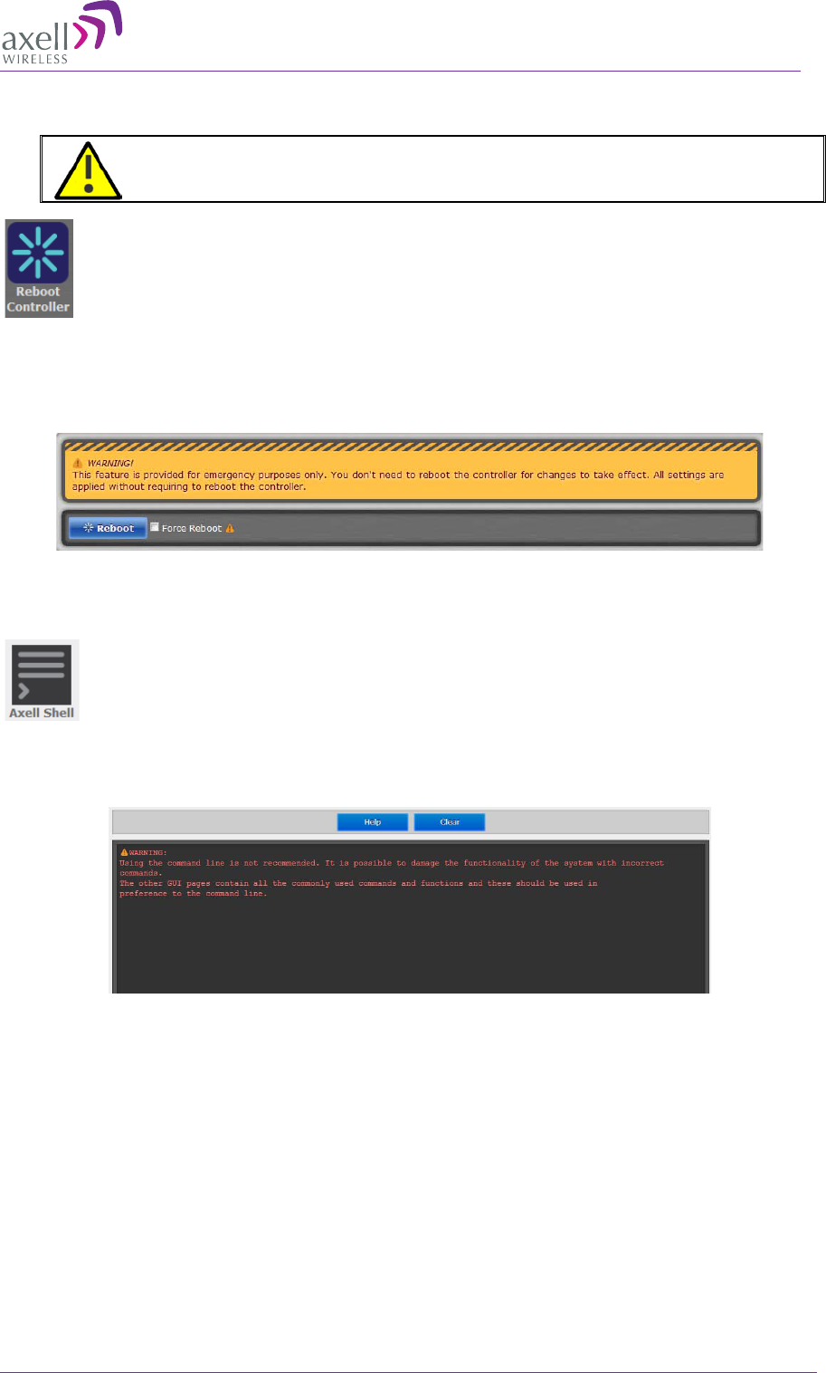
AXELL MBF-40 AMERICAS REPEATER
PRODUCT DESCRIPTION AND USER’S MANUAL
© Axell Wireless Ltd Doc. No. 00071UM Rev. 3.4 69
6.5 Reboot
CAUTION!! Use this function in Emergency Cases ONLY
To reboot the Control Module:
1. Click the Config tab.
2. Click on the Reboot icon.
3. Approve the Reboot sequence.
6.6 Axell Shell (Command Line Interface)
To access the Axell Shell:
1. Click on the Config button.
2. Select the Axell Shell option.
The Axell Shell button invokes the CLI pane. It is used to run some of the commands
that are currently not provided by the Web GUI (user privileges and administration)
and/or for advanced troubleshooting and configurations procedures.
All configuration and management procedures can be implemented using this interface.
Please refer to the Attribute Reference section (by clicking the Cofing button on the top
right and selecting Attribute Reference – see 6.7) for detailed syntax and available
commands. You may also consider viewing the MBF-40 Commands and Attributes
document.
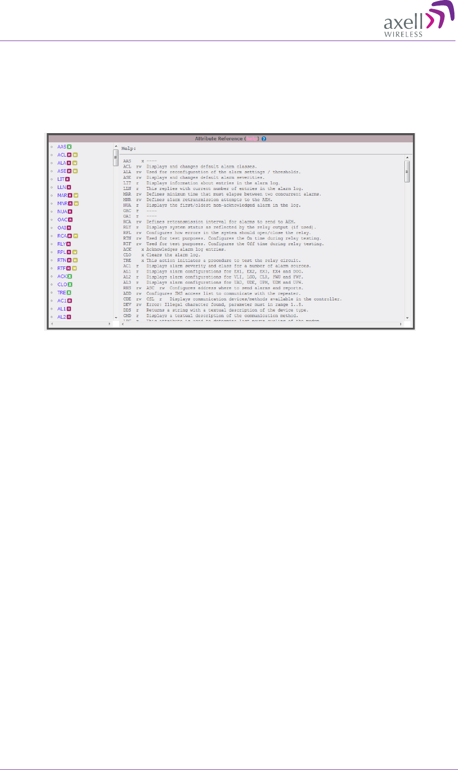
AXELL MBF -40 AMERICAS REPEATERS
PRODUCT DESCRIPTION AND USER’S MANUAL
70 Doc. No. 00071UM Rev. 3.4 © Axell Wireless Ltd
6.7 Attribute Reference
To access the Attribute Reference
1. Click on the Config button.
2. Select the Attribute Reference option.
The Attribute Reference lists all available CLI commands and includes details and
examples on how to use the commands. Additional information may be found in the
MBF-40 Commands and Attributes document.

AXELL MBF-40 AMERICAS REPEATER
PRODUCT DESCRIPTION AND USER’S MANUAL
© Axell Wireless Ltd Doc. No. 00071UM Rev. 3.4 71
7 Monitoring and Fault Sourcing
MBF-40 provides the following monitoring and fault sourcing options:
• Web GUI Home screen Advanced mode – shows general status of system and
components
• Web GUI Logs screen – provides logs of faults and operations
• Module LEDs – can be seen locally when opening the Repeater
This chapter describes these fault sourcing tools. Be sure to review the Cautions and
General Statements below.
Note the following
• The Input / Output RF level power level monitoring windows are for indication only
and should not be considered a replacement for laboratory test equipment accuracy
of measurement of actual signal levels. The error of measurement will be high at low
input levels.
• The normal operating range of signal measurement is as follows:
• Downlink Output range +20dBm to +43dBm
• Uplink Output range -10dBm to +5dBm
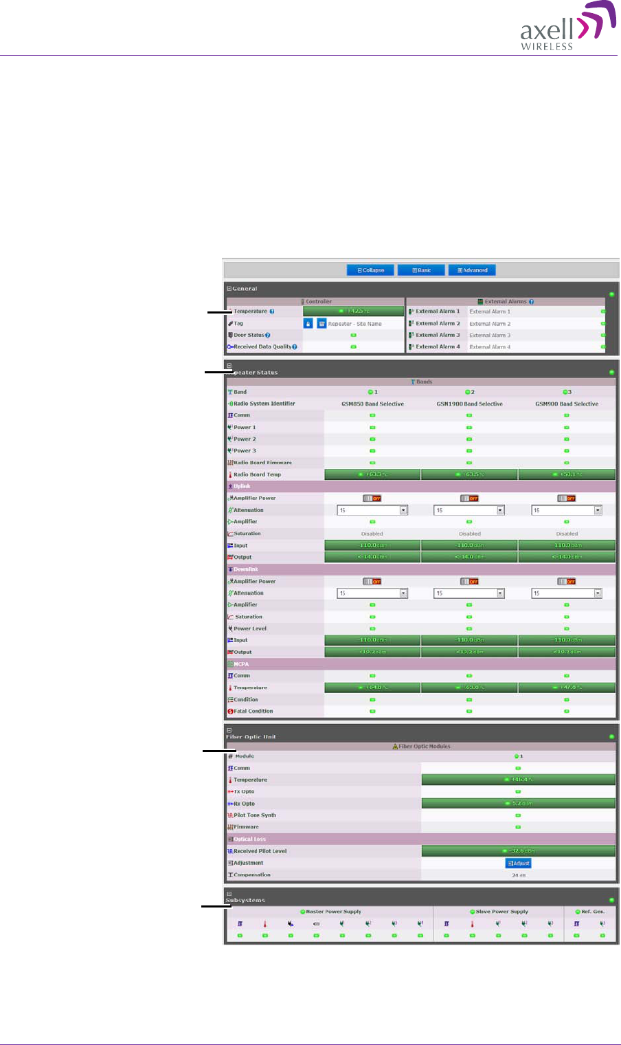
AXELL MBF -40 AMERICAS REPEATERS
PRODUCT DESCRIPTION AND USER’S MANUAL
72 Doc. No. 00071UM Rev. 3.4 © Axell Wireless Ltd
7.1 Monitoring Via the MBF-40 Home Screen
In addition to RF settings and readings, the MBF-40 Home screen provides detailed
information on the operation status of internal modules. This information can be used to
aid in remotely troubleshooting the Remote.
To access the MBF-40 Main Monitoring and Configuration window
1. Access the OMU II main windows, click the Nodes button, choose the remote related
node and click the adjacent Control button. The MBF-40 Home window appears in
Basic View. To view more details, click Advanced.
Figure 7-1: MBF-40 Main Screen Advanced
General
(Same as Basic
view)
Detailed Repeater
Status view
Detailed fiber optic
status
Power measurements
status

AXELL MBF-40 AMERICAS REPEATER
PRODUCT DESCRIPTION AND USER’S MANUAL
© Axell Wireless Ltd Doc. No. 00071UM Rev. 3.4 73
7.1.1 General Page Area
Figure 7-2: MBF-40 General
Indicator Description
Temperature Current ambient temperature
Tag Name of Repeater, user customizable
Door Status Green if closed
Received Data Quality Check data for consistencies
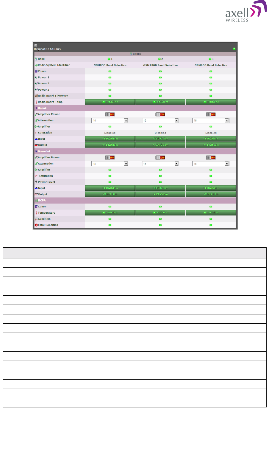
AXELL MBF -40 AMERICAS REPEATERS
PRODUCT DESCRIPTION AND USER’S MANUAL
74 Doc. No. 00071UM Rev. 3.4 © Axell Wireless Ltd
7.1.2 Detailed view of the MBF-40
Figure 7-3: MBF-40 Repeater Status
Indicator Description
Band Overall band status.
Radio System Identifier Band(s) and technologies in use
Comm DL/UL status
Power Power indication
Radio Board Firmware Firmware related error
Radio Board Temp Radio board temperature indicator
Amplifier Power Turn amp. on/off.
Attenuation Use to define DL/UL RF attenuation level per band
Amplifier Amplifier status
Saturation Saturation level status
Power Level Power supply status
Input/Output Input/output power levels
Comm Communication status
Temperature Temperature level and status indicator
Condition Signal conditioning status
Fatal Condition Critical condition indicator (RED = fault)
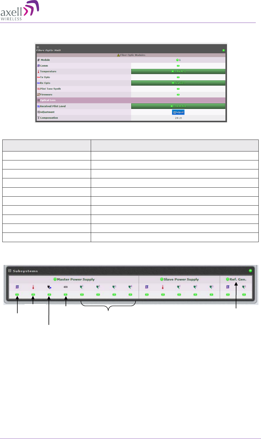
AXELL MBF-40 AMERICAS REPEATER
PRODUCT DESCRIPTION AND USER’S MANUAL
© Axell Wireless Ltd Doc. No. 00071UM Rev. 3.4 75
7.1.3 Detailed view of Fiber Optic Unit
Figure 7-4: MBF-40 F/O Status
Indicator Description
#Module Overall optic module status
Comm Optic connection status
Temperature
Temperature level and status indicator
Tx Opto DL optic signal status
Rx Opto UL optic signal strength and status
Pilot Tone Synth Pilot tone synthesizer status
Firmware Firmware related error
Received Pilot Level Pilot tone level received in optic module
Adjustment Perform UL OLA (on repeater side)
Compensation Compensation performed on the optic link
7.1.4 Subsystems
Comm.
Temp
Pwr.
input
Batt.
Status
Pwr.
modules
status
Reference
Generator
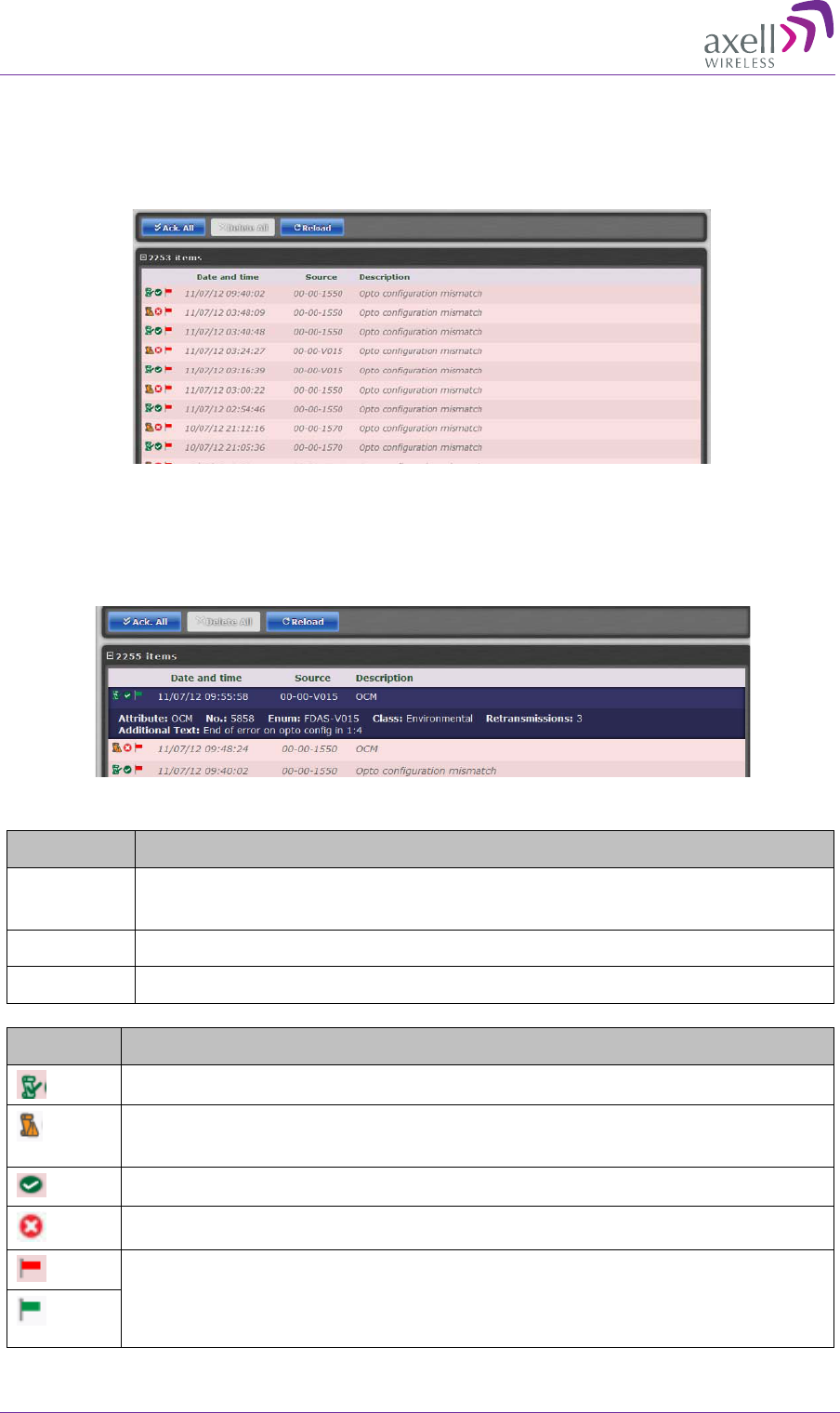
AXELL MBF -40 AMERICAS REPEATERS
PRODUCT DESCRIPTION AND USER’S MANUAL
76 Doc. No. 00071UM Rev. 3.4 © Axell Wireless Ltd
7.2 Logs Screen
The Alarms Log displays the last 100 alarms and/or user actions on the remote system
in a chronological order. By hovering with the mouse over each alarm, full alarm details
are available, including alarm descriptions, severities, alarm classes and time of event.
Figure 7-5: Logs
To receive a summary containing all information on a reported incident in the Log list,
simply hover with the mouse over the specified Log and view all details contained in the
Log (see below).
Figure 7-6: Logs – Summary
Column Description
Date &
Time Time of occurrence
Source ID of reporting source
Description Additional alarm information (e.g. Open Door)
Icon Description
Alarm attended to and cleared.
System alarm –
displayed when system functionality may be
compromised.
Alarm status: OK
Alarm status: Error
Acknowledge alarm – Green = Acknowledged.
Click to change acknowledgement.
Use the Ack All button to acknowledge all alarm logs.
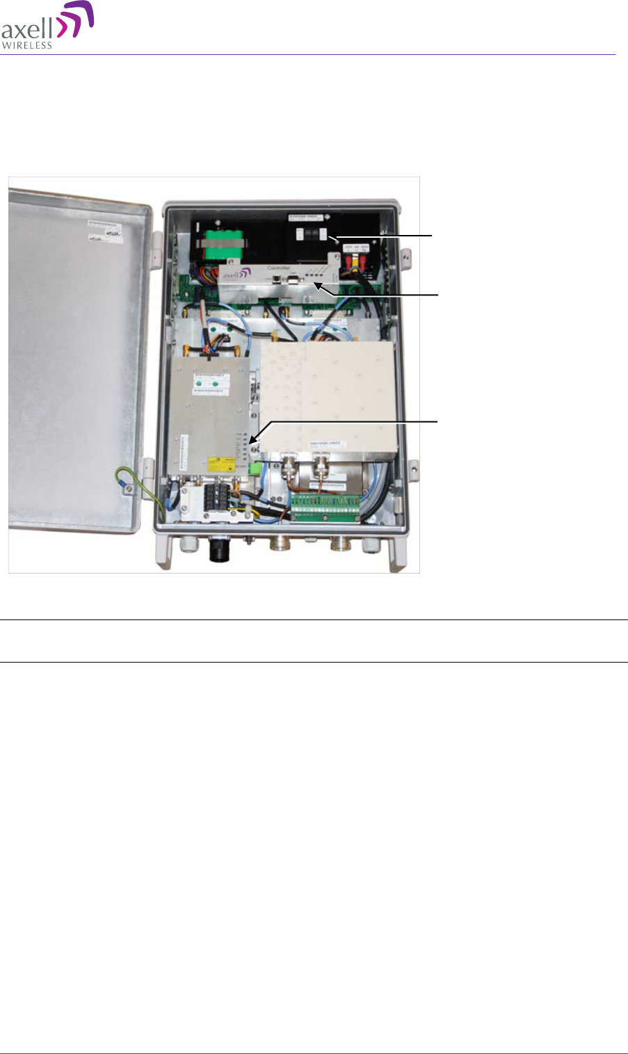
AXELL MBF-40 AMERICAS REPEATER
PRODUCT DESCRIPTION AND USER’S MANUAL
© Axell Wireless Ltd Doc. No. 00071UM Rev. 3.4 77
7.3 Module LEDs
This section describes the LEDs of the internal modules. The modules are accessed if the
remote is opened. An example of the MBF-40 Dual-band, dual-service antenna model is
given below:
Figure 7-7: Dual band Dual Service Antenna Model
NOTE: MIMO models include two optic converter modules with separate LED indicators. Both
modules’ LED status should be checked.
F/O converter module
LEDs, see 7.4.2
Controller module
LEDs, see 7.4.1
Power module LEDs,
see 7.4.3
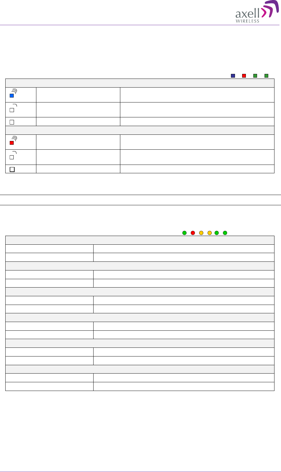
AXELL MBF -40 AMERICAS REPEATERS
PRODUCT DESCRIPTION AND USER’S MANUAL
78 Doc. No. 00071UM Rev. 3.4 © Axell Wireless Ltd
7.3.1 Control Module LEDs
The Control Module has four LEDs which give information regarding the status of the
MBF-40.
The two LEDs “Modem Power” and “Modem Status” do not fill any function and can
be disregarded.
Blue LED - Login
Quick flash Control Module switched on, someone logged in locally
and/or remotely
Off (except for a quick flash
every 10th second) Control Module switched on, no one logged in
Off (permanent) Control Module switched OFF
Red LED - Status
Quick flash Control Module switched on, one or more errors/alarms
detected
Off (except for a quick flash
every 10th second) Control Module switched on, status OK
Off (permanent) Control Module switched off
7.3.2 F/O Converter LEDs
NOTE: MIMO models include two optic converters with separate status LEDs.
There are 6 LEDs on the module to indicate the status.
LED 1, Power, Green
On Unit is powered on
Off Unit has no power
LED 2, Error, Red
On Error detected
Off
No error
LED 3, UL Data, Yellow
On Communication is ongoing in the uplink direction
Off No communication
LED 4, DL Data, Yellow
On Communication is ongoing in the downlink direction
Off No communication
LED 5, Opto Rx, Green
On Received RF signal on Fiber channel is above threshold
Off Input level below threshold
LED 6, Opto Tx, Green
On Transmitted RF signal on Fiber channel is above threshold
Off Output level below threshold
Modem Status
Modem Power
Status
Login
PWR
ERR
UL Data
DL Data
Opto Rx
Opto Tx
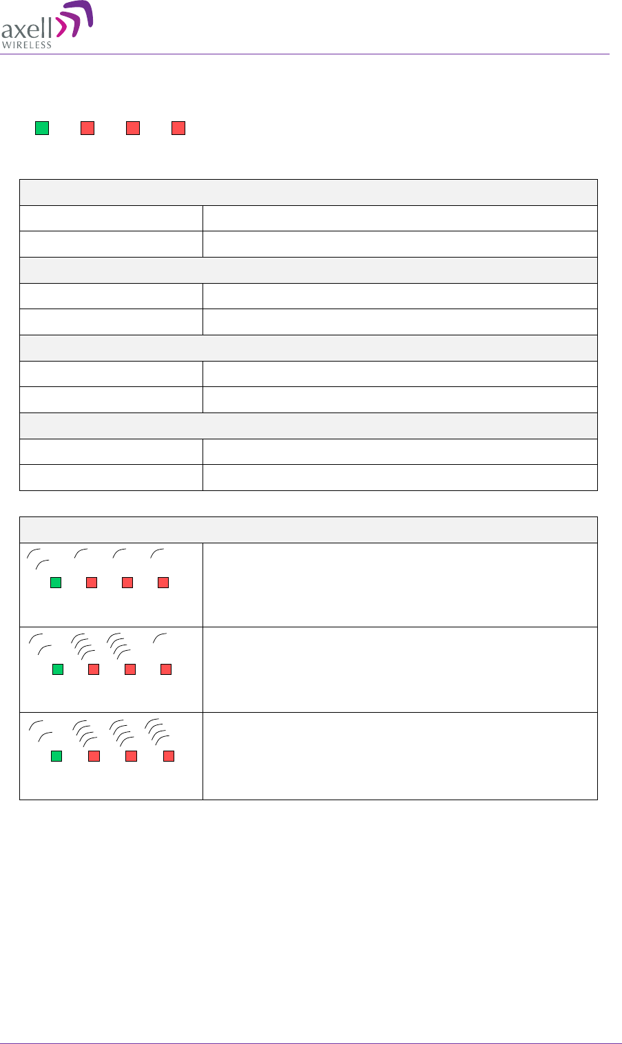
AXELL MBF-40 AMERICAS REPEATER
PRODUCT DESCRIPTION AND USER’S MANUAL
© Axell Wireless Ltd Doc. No. 00071UM Rev. 3.4 79
7.3.3 Power Supply LEDs
This section provides a detailed description of the LEDs and fault examples.
LED 1, Input Power, Green
Slow flash Power supply unit operating on AC or DC
OFF Power supply unit not operating
LED 2, +6V, Red
Slow flash (every 10 seconds) +6V power supply operating
Quick flash +6V power supply not operating or operating with malfunction
LED 3, +15V, Red
Slow flash (every 10 seconds) +15V power supply operating
Quick flash +15V power supply not operating or operating with malfunction
LED 4, +28V, Red
Slow flash (every 10 seconds) +28V power supply operating
Quick flash +28V power supply not operating or operating with malfunction
Examples
LED 1 is flashing slowly, LED 2 – 4 are flashing slowly (once every
10 seconds)
=> power supply unit is operating without problem
LED 1 is flashing slowly, one or two of the red LEDs are flashing
quickly
=> Input power is operating but there is a problem with some of the
other voltages
LED 1 is flashing slowly, all of the red LEDs are flashing quickly
=> Input power is out and unit is operating on backup battery
Input
Power +6V +15V +28V
Input
Power +6V +15V +28V
Input
Power +6V +15V +28V
Input
Power +6V +15V +28V

AXELL MBF -40 AMERICAS REPEATERS
PRODUCT DESCRIPTION AND USER’S MANUAL
80 Doc. No. 00071UM Rev. 3.4 © Axell Wireless Ltd
8 Maintenance
8.1 Cautions and General Statements
• The system normally operates without any operator intervention or maintenance. If
in the unlikely event of any unit failure, the faulty repeater should be replaced. A
failed unit can be removed and replaced with a spare while the rest of the system
(other repeaters) is still operating. However, the power supply of the failed repeater
should be isolated from the power before anything is replaced.
• In the event of a malfunction in the system, the status of the antenna systems as
well as the continuity of the cabling should be checked before replacing any modules
within the repeater.
• The Input / Output RF level power level monitoring windows are for indication only
and should not be considered a replacement for laboratory test equipment accuracy
of measurement of actual signal levels. The error of measurement will be high at low
input levels.
• The normal operating range of signal measurement is as follows:
• Downlink Output range +20dBm to +43dBm
• Uplink Output range -10dBm to +5dBm
• In the event of a failure Axell Wireless’s support service should be contacted for
advice on a possible module replacement or other action to be taken.
• If a shipment of a repeater back to Axell Wireless is made within the period of
guarantee the original packing must be used.
• Component Replacement - None of the modules in the repeater can be replaced
without removing the repeater from its mounting and opening the cover of the
repeater.
• Product Disposal - Disposal of this product must be handled according to all national
laws and regulations. For detailed information regarding materials, please refer to
Axell Wireless.
CAUTION!!
Please be aware that the eq
uipment may, during certain conditions
become very warm and can cause minor injuries if handled without any
protection, such as gloves.

AXELL MBF-40 AMERICAS REPEATER
PRODUCT DESCRIPTION AND USER’S MANUAL
© Axell Wireless Ltd Doc. No. 00071UM Rev. 3.4 81
8.2 Batteries
The Repeater contains two types of batteries:
• A battery pack in the power supply unit, consisting of 8X NiMh batteries.
• A button cell CR1216 on the controller board.
CAUTION!!
Please be aware that the equipment may, during certain conditions become
very warm and can cause minor injuries if handled without any protection,
such as gloves.
Risk of explosion if battery is replaced by an incorrect type. Dispose of used
batteries according to local laws and instructions.
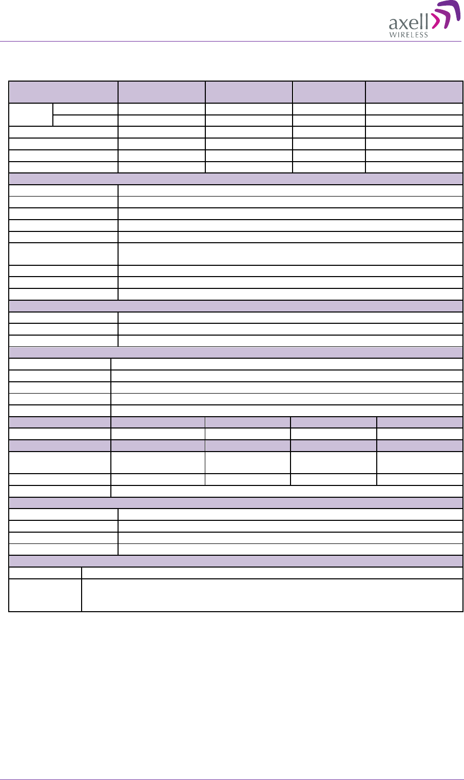
AXELL MBF -40 AMERICAS REPEATERS
PRODUCT DESCRIPTION AND USER’S MANUAL
82 Doc. No. 00071UM Rev. 3.4 © Axell Wireless Ltd
Appendix A - US Specifications
Frequency Range
Uplink (UL)
Downlink (DL)
Operational BW
Composite Output
Power (*)
LTE700
Lower band
698-716MHz
728-746MHz
29MHz
+37 dBm
Upper band
776-787MHz
746-757MHz
29MHz
+37 dBm
800MHz (Sprint)
817-824 MHz
862-869 MHz
32MHz
+37 dBm
850MHz (Cellular)
824-849MHz
869-894MHz
32MHz
+37 dBm
1900MHz (PCS)
1850-1915MHz
1930-1995MHz
65MHz
+37 /+43 dBm**
1700MHz (AWS)
1710-1755MHz
2110-2155MHz
45MHz
+39 / +43 dBm**
General Parameters
Noise Figure
3dB Typical (maximum gain)
Ripple
±2dB
Propagation Delay
< 2µs
Gain UL/DL
Adjustable, in 1dB steps
System Impedance
50Ω
Return loss at antenna
connections
>14dB
Antenna Connectors
DIN 7/16
No. of antenna orts
1 for single/dual/tri/quad band, 2 connectors for MIMO
Electrical ratings
115VAC 60Hz, -48VDC
Optical Parameters
Wavelength DL/UL
1310/1550nm
Max optical Loss
10dBo
F/O Connector
1 SC/APC for SISO, 2 for MIMO
Modulation Accuracy at nominal output power
GSM/GMSK
<2.5º RMS and <10º peak
EDGE/8-PSK
<3% EVM RMS
WCDMA/EVM
<12.5% RMS (composite according to ETSI TS 25.106 with TM1/64 DPCH
LTE/EVM
< 8% (composite according to 3GPP TS 136 106)
PkCDE
<-33dB (ETSI TS 25.106 with TM 1/64 DPCH and spreading factor 256)
Power Consumption
Single Band
Dual Band
Tri Band
Quad Band
140W
220W / 350W ***
350W
400W
Mechanical
Single Band
Dual Band
Tri Band
Quad Band
Dimensions 21.3” x 15” x 7.8”
540 x 382 x 198mm
21.3” x 15” x 7.8”
540 x 382 x 198 mm
21.3” x 15” x 12.3”
540 x 382 x 313 mm
21.3” x 15” x 12.3”
540 x 382 x 313 mm
Weight
44lbs (20kg)
48.5lbs (22kg)
76lbs (34kg)
82lbs (37kg)
Enclosure
Aluminum (IP65)
Environmental
EMC
FCC
Operating Temperature
-77 to +121ºF (-25 to +50ºC)
Storage Temperature
-86 to +158ºF (-30 to +70ºC)
Humidity
ETSI EN 300 019-2-4 (see compliance below)
Complies With
Radio
FCC parts 22, 24 and 27 where applicable.
Safety
UL 60 950-1, 1st Edition ”Information Technology Equipment
– Safety - Part 1: General requirements"
UL 50, 11th Edition “Enclosures for Electrical Equipment”
* In repeaters that share a common downlink Fiber for 900MHz and 1800MHz a minimum of 4 carriers in each
band is required for the full composite output power to be attainable maintaining full ETSI compliance.
** The composite output power is model dependent.
*** Power consumption of all dual-band models except for MBF-4317-4319, is 220W. Power consumption for
MBF-4317-4319 is 350 W.
AXELL MBF-40 AMERICAS REPEATER
PRODUCT DESCRIPTION AND USER’S MANUAL
© Axell Wireless Ltd Doc. No. 00071UM Rev. 3.4 83
Appendix B - Canada Specifications
Frequency Range
Uplink (UL)
Downlink (DL)
Operational BW
Composite Output
Power (*)
LTE700
Lower band
698-716MHz
728-746MHz
29MHz
+43dBm
Upper band
776-787MHz
746-757MHz
29MHz
+43dBm
850MHz (Cellular)
824-849MHz
869-894MHz
25MHz
+43dBm
1900MHz
1850-1915MHz
1930-1995MHz
65MHz
+43dBm
1700MHz (AWS)
1710-1755MHz
2110-2155MHz
45MHz
+43dBm
2600MHz
2500-2570MHz
2620-2690MHz
70MHz
+43dBm
General Parameters
Noise Figure
3dB Typical (maximum gain)
Ripple
±2dB
Propagation Delay
< 2µs
Gain UL/DL
Adjustable, in 1dB steps
System Impedance
50Ω
Return loss at antenna
connections
>14dB
Antenna Connectors
DIN 7/16
No. of antenna ports
1 for single/dual/tri/quad band, 2 connectors for MIMO
Electrical ratings
115VAC 60Hz, -48VDC
Cooling
Convection in single, dual and tri-band. Quad-band requires fan hood
Optical Parameters
Wavelength DL/UL
1310/1550nm
Max optical Loss
10dBo
F/O Connector
1 SC/APC for SISO, 2 for MIMO
Modulation Accuracy at nominal output power
GSM/GMSK
<2.5º RMS and <10º peak
EDGE/8-PSK
<3% EVM RMS
WCDMA/EVM
<12.5% RMS (composite according to ETSI TS 25.106 with TM1/64 DPCH
LTE/EVM
< 8% (composite according to 3GPP TS 136 106)
PkCDE
<-33dB (ETSI TS 25.106 with TM 1/64 DPCH and spreading factor 256)
Power Consumption
Single Band
Dual Band
Tri Band
Quad Band
140W
220W
350W
400W
Mechanical
Single Band
Dual Band
Tri Band
Quad Band
Dimensions 21.3” x 15” x 7.8”
540 x 382 x
198mm
21.3” x 15” x 7.8”
540 x 382 x 198 mm
21.3” x 15” x 12.3”
540 x 382 x 313 mm
21.3” x 15” x 12.3”
640 x 382 x 313 mm
Weight
44lbs (20kg)
48.5lbs (22kg)
76lbs (34kg)
83lbs (38kg)
Enclosure
Aluminum (IP65)
Environmental
EMC
IC
Operating Temperature
-77 to +121ºF (-25 to +50ºC)
Storage Temperature
-86 to +158ºF (-30 to +70ºC)
Humidity
ETSI EN 300 019-2-4 (see compliance below)
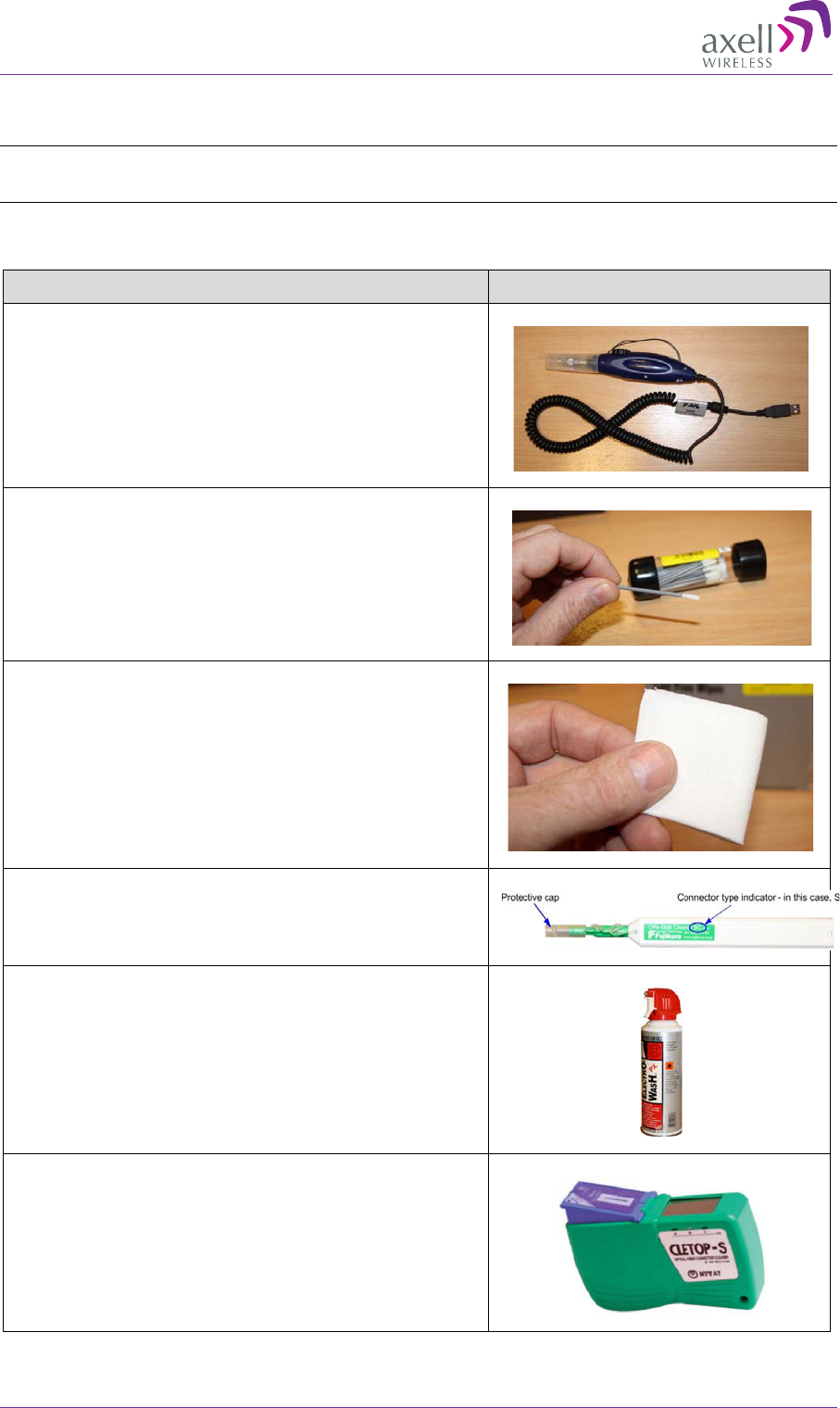
AXELL MBF -40 AMERICAS REPEATERS
PRODUCT DESCRIPTION AND USER’S MANUAL
84 Doc. No. 00071UM Rev. 3.4 © Axell Wireless Ltd
Appendix C – F/O Cleaning Procedure
NOTE: The process is demonstrated on an OMU F/O module and is similar to all F/O equipment
supplied by Axell.
Tools
Tool Description Illustration
Fiber
scope connected to a PC running the
appropriate viewing software.
It is highly recommended that some form of
Fiber viewing equipment such as a Fiberscope is
used to ensure that all Fiber
connections are
clean before termination; failure to do so could
result in poor system performance
Lint-free swabs (box), Axell P/N 99-000127
Lint-free wipes (pack) Axell P/N 99-000125
Fujikura “One Click” cleaner
Axell P/N 98-900004.
99% isopropyl alcohol (can), Axell P/N 99-
000126
Cletop type S Cassette Cleaner, Axell P/N 98-
900001
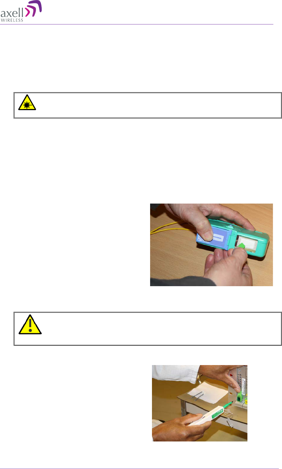
AXELL MBF-40 AMERICAS REPEATER
PRODUCT DESCRIPTION AND USER’S MANUAL
© Axell Wireless Ltd Doc. No. 00071UM Rev. 3.4 85
F/O Cleaning Procedure
There are two types of procedures:
• Dry
• Web
Dry Cleaning
ATTENTION!!
Invisible laser radiation might be emitted from
disconnected Fibers or connectors. Do not stare into beams or view
directly with optical instruments.
1. Before cleaning the optical connectors on the OMU it is advisable to clean the
connector of the mating cable being attached to the optical port.
An unclean optical connector is often the cause for reduced system performance. A
bit of dust or oil from a finger can easily interfere with, or block light. Fortunately, it
is very easy to clean the connector. Be sure to use the correct procedure for the
given connector. When disconnected, cap the SC/APC connector to keep it clean and
prevent scratching the tip of the ferrule.
Use a product specially designed for the
purpose, such as the Cletop type S Cassette
Cleaner.
2. Begin by dry cleaning the F/O bulkhead connector (shown below is the Fujikura One-
Click in use).
IMPORTANT!! Always make sure there is a way of inspecting the
connector after cleaning. Cleaning can actually leave the end-face in a
worse condition, since alcohol residue is one of the most difficult
contaminants to remove.
3. Remove the protective cap from
the cleaning-head end of the
“One Click” cleaner, lift the
protective end-cap on the Fiber
connector and offer-up the end
to the Fiber connector

AXELL MBF -40 AMERICAS REPEATERS
PRODUCT DESCRIPTION AND USER’S MANUAL
86 Doc. No. 00071UM Rev. 3.4 © Axell Wireless Ltd
4. With the cleaning-head end
fully engaged in the connector,
push until an audible “click” is
heard
5. Without fully withdrawing the
cleaning head end push it in
again twice more, each time
until an audible “click” is heard.
6. Withdraw the “One Click”
cleaner and replace the
protective end cap.
7. Inspect the Fiber connector using a Fiberscope. On the PC monitor, verify that
there is no contamination present on the connector end-face.
8. If the connector is dirty, clean it with a wet cleaning technique followed
immediately by dry cleaning. This is to remove any remaining residue from the
wet clean (the following steps demonstrate a wet cleaning technique).
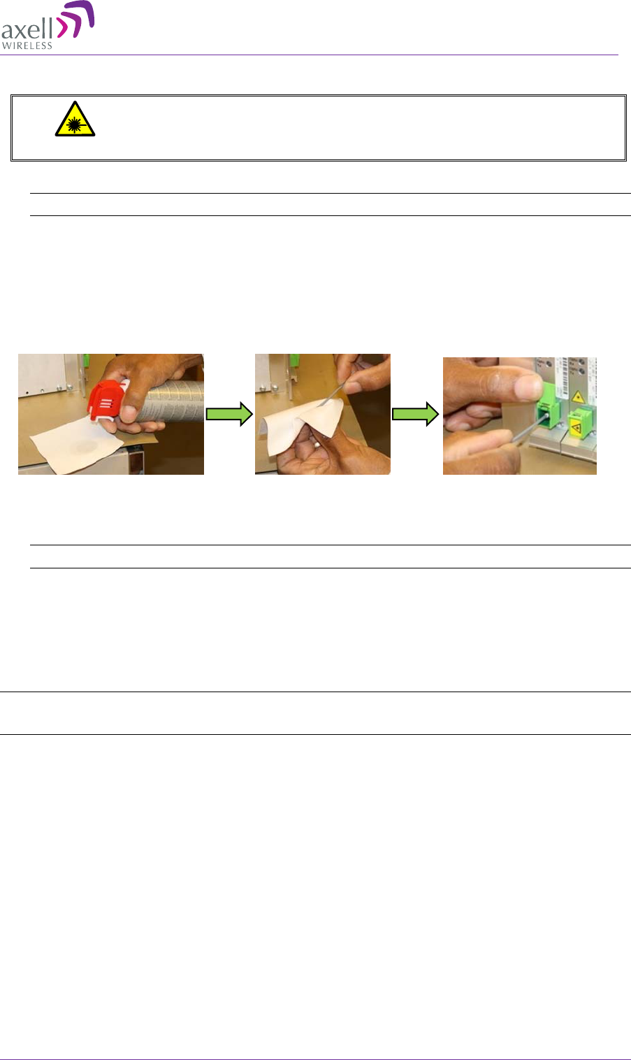
AXELL MBF-40 AMERICAS REPEATER
PRODUCT DESCRIPTION AND USER’S MANUAL
© Axell Wireless Ltd Doc. No. 00071UM Rev. 3.4 87
Wet Cleaning
ATTENTION!
Invisible laser radiation might be emitted from disconnected fibers
or connectors. Do not stare into beams or
view directly with optical
instruments.
1. Lightly moisten a new lint-free wipe with 99% isopropyl alcohol. (Step 1 below).
Tip: Have a dry lint-free swab available for immediately drying after performing the wet-cleaning.
2. Lightly press and turn a clean lint-free swab in the moistened area of the wipe to
moisten the swab. It is important that the swab is not too wet. (Step 2 below).
3. Insert the moistened lint-free swab into the bulkhead adapter. Lightly press and
rotate several times in the same direction (Step 3 below).
Figure 8-1: Wet-Cleaning Technique
4. Immediately use a dry lint-free swab to clear any remaining alcohol residue.
NOTE: Do not re-use any of the wipes and/or swabs. Dispose of them properly.
5. Follow steps 3 to 6 of Dry Cleaning above
6. Re-inspect the Fiber using the Fiberscope. On the PC monitor, verify that there is no
contamination present on the connector end-face.
7. If the Fiber is still dirty, go back to step 1 (Wet Cleaning) and repeat the entire
process.
NOTE: The entire wet/dry cleaning cycle should only be used twice, if the Fiber is still dirty after two
cycles of wet/dry cleaning seek advice from the Axell Wireless Support Desk.
Step 1
Step 2
Step 3