Axesstel AXWD1900 Wireless Modem (PCS CDMA) User Manual EVDO vDraft
Axesstel Inc Wireless Modem (PCS CDMA) User Manual EVDO vDraft
Axesstel >
Users Manual
1xEV-DO Wireless Broadband Modem AXW-D800/D1900
Axesstel 1
Axesstel 1xEV-DO Wireless Modem
User Manual
Rev: 0.01.01
Axesstel, Inc.
1xEV-DO Wireless Broadband Modem AXW-D800/D1900
Axesstel 2
Table of Contents
Introduction ____________________________________________________ 3
Features _______________________________________________________ 3
Safety Precaution________________________________________________ 4
Contents _______________________________________________________ 5
Desktop Installation______________________________________________ 6
Wall Mount Installation ___________________________________________ 6
Getting to know the modem _______________________________________ 7
Connecting Axesstel EVDO Wireless Modem_________________________ 8
Configuring Your Wireless Modem _________________________________ 9
USB Driver Installation __________________________________________ 14
TCP/IP Settings ________________________________________________ 16
Troubleshooting________________________________________________ 18
SPECIFICATIONS_______________________________________________ 19
1xEV-DO Wireless Broadband Modem AXW-D800/D1900
Axesstel 3
Introduction
Axesstel's 1xEv-DO Broadband Wireless Modem allows users to "get
connected" to high speed data services with unprecedented ease. Powered by
QUALCOMM's MSM6500 processor, these modems provide high speed data
service through USB and Ethernet interfaces at rates of up to 2.4Mbps
download and 153.6 Kbps upload. With RJ-45 Ethernet connection, the users
can enjoy true plug and play connection without driver installation.
Features
z CDMA 1xEV-DO data service with speed up to 2.4Mbps download and
153.6Kbps upload
z Backward compatible to CDMA2000 1xRTT Data service (153.6 Kbps
max)
z Receive diversity (2 antennas) for enhanced RF performance
z 4 LED indicators (Power, Signal Strength, Connection, and Ethernet)
z RJ-45 Ethernet and High Speed USB 1.1 data port
z Web based Admin tool
z Desktop or Wall-Mountable
z Optional Range-extending Patch Antenna
1xEV-DO Wireless Broadband Modem AXW-D800/D1900
Axesstel 4
Safety Precaution
1. Avoid placing the unit in a dusty location, or near a source of gas or fire.
2. Do not shake, hit or drop the unit.
3. To clean the unit, use only a soft, dry cloth. The chemicals in alcohol,
benzine or acetone can damage the surface of the unit.
4. Do not twist or pull the cord out of the unit.
5. Do not disassemble the phone.
6. DO NOT use the power adapter if the power cord is damaged or the unit has
been dropped or damaged in any way.
7. Only use the power adaptor provided by Axesstel. Do not use the
AXESSTEL adapter for any other purpose.
8. Use only the antenna provided with the unit. Do not use the antenna for
any other purpose.
9. Do not use the unit near water, for example, near a bathtub, sink, wet
basement, or swimming pool.
NOTE: The input voltage and the shape of the plug on this phone may vary
from country to country.
1xEV-DO Wireless Broadband Modem AXW-D800/D1900
Axesstel 5
Contents
After opening the package, check to make sure that you have all the parts
shown below. If any piece is missing or broken, please call your agent or
customer service. Items marked optional may be available only on select
models.
1. Main Unit 4. User’s Manual
2. Antenna (2) 5. USB Cable (Optional)
3. AC/DC Adapter and AC Cord 6. Ethernet Cable (Optional)
1xEV-DO Wireless Broadband Modem AXW-D800/D1900
Axesstel 6
Desktop Installation
The 1xEV-DO Modem operates by receiving electricity from an electrical outlet.
1 Connect the antennas on the connectors of each side of the unit..
2 Connect the Modem to computer using RJ-45 Ethernet Cable (CAT 5) or USB
cable.
3 Move the connection selector switch to USB or Ethernet.
4 Connect the power adaptor to the DC 9V socket of the modem.
4 Plug the AC adaptor into an appropriate electrical wall outlet.
5 Turn on the power switch located next to the DC 9V socket.
Wall Mount Installation
1 Mark two mounting holes on the wall using the hole locator on the last page of
the manual.
2 Drill two holes at the marked locations.
3 Tighten the screws until the head is about 5mm from the wall.
4 Hang the modem on the screw using the two holes in the back.
5 Push the modem down until the unit is firmly locked into place.

1xEV-DO Wireless Broadband Modem AXW-D800/D1900
Axesstel 7
Getting to know the modem
LED indications
LED Color Meaning
Green Power is on
Power Off Power is off
Green Excellent Signal
Orange Good Signal
Red Poor Signal
Signal
Off No Signal or Service is present
Green Modem is connected to the CDMA network
Connect Off Modem is not connected
Green PC connected to the Ethernet
Blinking Indicates data activity
Ethernet
Off No PC is connected to the Ethernet
Power ON/OFF Switch
There’s power switch on the front side of the modem.
Turn on the modem by moving switch to ON position. Turn off the modem by
moving switch to OFF position.
NOTE: When you turn on the modem, it automatically searches for service
signal. When it successfully acquires service signal, the signal LED turns to
green, orange or red.
Connection Type Switch
Connection Type Switch is located between Ethernet port and USB port. Set
this switch to Ethernet or USB depending on type of connection you are using.
1xEV-DO Wireless Broadband Modem AXW-D800/D1900
Axesstel 8
Connecting Axesstel EVDO Wireless Modem
Before you start
1. Make sure that your account is active. Please contact your ISP for
account setup and activation information.
2. Configure your PC to obtain TCP/IP settings automatically from DHCP
server feature of Wireless Modem. Refer to “TCP/IP Settings” for more
information on how to set up TCP/IP settings on your PC.
3. In order to connect multiple PCs to Wireless Modem and share internet
connection, you will need a Broadband Router, Ethernet Switch, or Hub.
Please refer to instructions on your Broadband Router for information on
connecting multiple PCs.
Connection using Ethernet port
1. Connect coaxial cable to Ethernet port of Wireless Modem.
2. Connect other end of coaxial cable to RJ-45 port of your PC’s Ethernet
network adapter or a network device, such as router or hub.
3. Connect the included Power Adapter to Power connector of Wireless
Modem. Connect the other end of Power Adapter to an electrical outlet.
4. Power on Wireless Modem.
5. It will take few seconds for Wireless Modem to establish a connection.
1xEV-DO Wireless Broadband Modem AXW-D800/D1900
Axesstel 9
Connection using USB port
1. Power off your PC.
2. Connect the included USB Cable to USB port on your PC.
3. Connect other end of USB Cable to USB port on Wireless Modem.
4. Connect the included Power Adapter to Power connector of Wireless
Modem. Connect the other end of Power Adapter to an electrical outlet.
5. Power on Wireless Modem.
6. Power on your PC. During the boot up process, your PC will recognize
Wireless Modem and ask to install Wireless Modem drivers. You need to
install Wireless Modem USB driver that was supplied with Wireless
Modem. Refer to “USB Driver Installation” for more information.
Configuring Your Wireless Modem
Wireless Modem provides an embedded Web-based Management Utility.
Configure your Wireless Modem by using your Web Browser.
Log In
• Open Web browser and enter IP address of Wireless Modem. Default IP
address of Wireless Modem is 192.168.0.1
• When prompt for User name and password, enter admin/admin.
• Click on appropriate tab to access System, Network, Security, or Status
settings.
1xEV-DO Wireless Broadband Modem AXW-D800/D1900
Axesstel 10
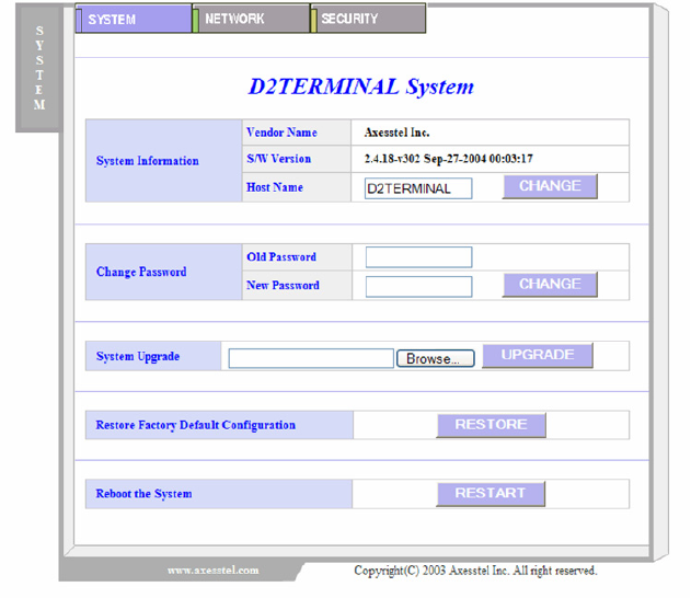
System Window
Host Name: Name of the Wireless Modem. You may change this
name according to your network need.
Change Password: To change the password of your account, enter your old
password and new password.
System Upgrade: To download new firmware.
Restore Default: Restore all settings to factory default settings.
Reboot System: Restart Wireless Modem.
1xEV-DO Wireless Broadband Modem AXW-D800/D1900
Axesstel 11
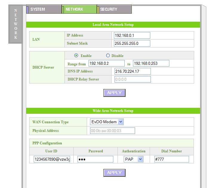
Network
IP Address: IP address of Wireless Modem. You will access Web-
based Configuration through this address.
DHCP Server: Enable if using Dynamic IP Address.
DHCP Server IP Range: Range of IPs that can be assigned by the DHCP
Server to each PC.
PPP Configuration: Enter User ID, Password, Authentication type, and dial
number of your wireless data network account.
APPLY: After making changes to Network settings, always
click APPLY button to saves changes.
1xEV-DO Wireless Broadband Modem AXW-D800/D1900
Axesstel 12
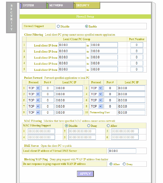
Security
Firewall Support: Enable/Disable built-in firewall feature.
Client Filtering: Local Client PC group can not access specified remote
application.
Packet Forward: Enable specific ports to be opened for specific
applications.
MAC Filtering: Block specific MAC addresses.
DMZ Server: Open a virtual server to public.
Blocking WAN Ping: Deny Ping request from WAN IP.
APPLY: Click APPLY to apply any of the Security setting changes.
1xEV-DO Wireless Broadband Modem AXW-D800/D1900
Axesstel 13
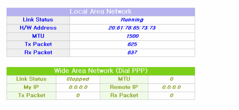
Status
Local Area Network: Current operation and connection status of LAN.
Wide Area Network: Current operation and connection status of WAN.
1xEV-DO Wireless Broadband Modem AXW-D800/D1900
Axesstel 14
USB Driver Installation
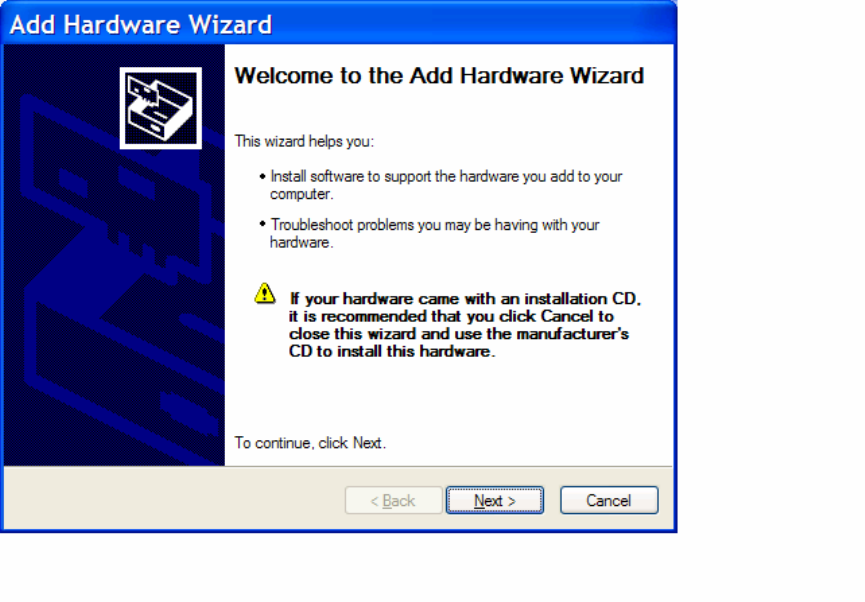
Power on the PC. After the boot up process, you will see Found New Hardware
screen and Add New Hardware Wizard screen.
Insert 1xEV-DO Wireless Modem Installation CD into CD-ROM drive of PC.
Select Specify the location of the driver (Advanced) and click Next.
Follow the onscreen prompts to install the software driver from the CD. The
software is located under “Drivers” folder named “USB_Driver”.
When windows locates the device driver, click Next. PC will copy the necessary
driver files from the CD.
1xEV-DO Wireless Broadband Modem AXW-D800/D1900
Axesstel 15
Click Finish after files are installed. Click Yes to re-start PC.
USB Driver Installation is completed.
1xEV-DO Wireless Broadband Modem AXW-D800/D1900
Axesstel 16
TCP/IP Settings
You will need to configure your PC to request IP address dynamically from the
gateway.
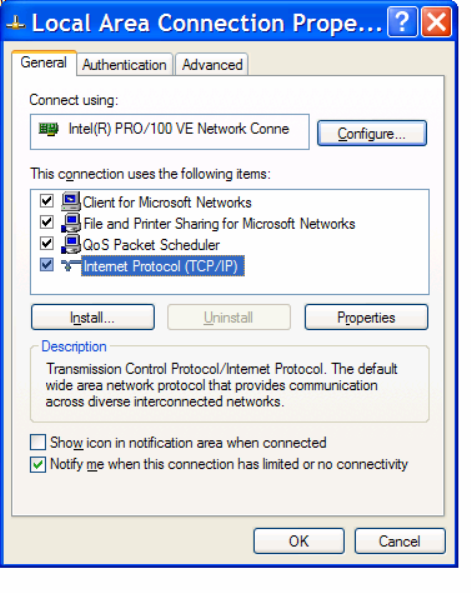
Click the Start button, select Settings, and select Control Panel. Double click the
Network Connection icon. Go to Local Area Connection Properties. Select the
TCP/IP protocol line that has been associated with your network card. If there is
no TCP/IP line listed, you will need to install TCP/IP first.
Click the Properties of the TCP/IP component.
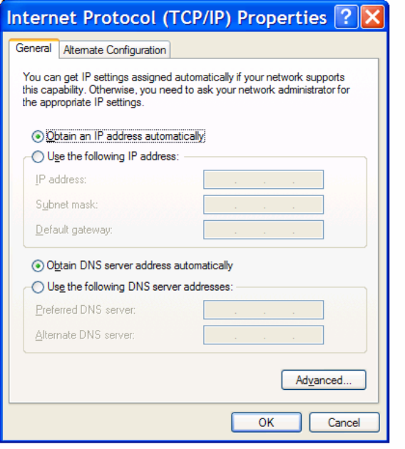
Choose Obtain an IP address automatically.
1xEV-DO Wireless Broadband Modem AXW-D800/D1900
Axesstel 17
Choose Obtain DNS Server address automatically.
Click Ok to exit Properties. If asked to re-start the PC, click YES.
1xEV-DO Wireless Broadband Modem AXW-D800/D1900
Axesstel 18
Troubleshooting
Q: My Wireless Modem is not working.
A: Check for the appropriate power indication on the LED. If no power, check
the adaptor (or External Power Supply) connection between the electrical
outlet and the modem. Check for the appropriate Received Signal Strength
Indication (RSSI), Power, and Message Indication through the designated
LED, respectively.
Q: I can’t get good signal. My connection is unstable.
A: Use Signal LED to check signal strength of current connection. If Signal LED
is showing red, it means current signal is weak. Try placing Wireless Modem
at different locations or Rotating Wireless Modem to different direction.
Avoid areas with high level of radio interference.
Q: I can’t connect to the Internet.
A: Check with your ISP to ensure your account was properly setup and it is
active. Then check TCP/IP settings of your PC and make sure your PC is
obtaining IP address automatically from Wireless Modem. For more
information on TCP/IP settings, Refer to “TCP/IP Settings”
Q: How do I renew PC’s IP?
A: Use IP repair feature in the connection. Or use Command window as
following.
1. Click Start and Click Run.
2. Type cmd in the prompt and click OK.
3. In Command Prompt (C:\), type ipconfig/release and press Enter.
4. In Command Prompt (C:\), type ipconfig/renew and press Enter.
5. Exit the Command Prompt.

1xEV-DO Wireless Broadband Modem AXW-D800/D1900
Axesstel 19
SPECIFICATIONS
AXW-D800 TX: 824.64 ~ 848.37 MHz
RX: 869.64 ~ 893.37 MHz Frequency
Range AXW-D1900 TX: 1850 ~ 1909.95 MHz
RX: 1930 ~ 1909.95 MHz
Channel Bandwidth CDMA 1.25 MHz
USB Connector 1 Type B
Ethernet Connector 1 RJ-45
Power Supply (Adapter) Input: AC 110~240V 50~60Hz
Output: DC 9V 1A
Temperature of operation
Relative humidity
-20°C~ +50°C
5% ~ +90%
Temperature of storage -25°C ~ +75°C
Dimension 160 x 197 x 50 (mm)
Weight (without internal battery) 540g

Safety Information
1 . SAFETY INFORMATION FOR FIXED WIRELESS TERMINALS
.POTE NTIALLY EXPLOSIVE ATMOSPHERES
Turn your phone OFF when in any area with a potentially explosive atmosphere
and obey all signs and instructions. Sparks in such areas could cauls e an
explosion or fire resulting in bodily injury or even death.
.
INTERFERENCE TO MEDICAL DIVICES
Certain electronic equipment may be shielded against RF signal from you wireless
phone. (pacemakers, Hearing Aids, and so on) Turn your phone OFF in health care
facilities when any regulations posted in these areas instruct you to do so.
RF signals may affect improperly installed or inadequately shielded electronic
system in motor vehicles.
.EXPOSURE TO RF ENERGY
Use only the supplied or an approved replacement antenna.
Do not touch the antenna unnecessarily when the phone is in use.
Do not move the antenna close to, or touching any exposed part of the body when
making a call.

SAR INFORMATION
THIS MODEL PHONE MEETS THE GOVERNMENT’S
REQUIREMENTS FOR EXPOSURE TO RADIO WAVES.
Your wireless modem is a radio transmitter and receiver. It is designed and manufactured not to
exceed the emission limits for exposure to radiofrequency (RF) energy set by the Federal
Communications Commission of the U.S. Government. These limits are part of comprehensive
guidelines and establish permitted levels of RF energy for the general population. The
guidelines are based on standards that were developed by independent scientific organizations
through periodic and thorough evaluation of scientific studies. The standards include a
substantial safety margin designed to assure the safety of all persons, regardless of age and
health. The exposure standard for wireless mobile phones employs a unit of measurement
known as the Specific Absorption Rate, or SAR. The SAR limit set by the FCC is 1.6 W/kg. *
Tests for SAR are conducted with the phone transmitting at its highest certified power level in all
tested frequency bands. Although the SAR is determined at the highest certified power level,
the actual SAR level of the phone while operating can be well below the maximum value. This is
because the phone is designed to operate at multiple power levels so as to use only the power
required to reach the network. In general, the closer you are to a wireless base station antenna,
the lower the power output. Before a phone model is available for sale to the public, it must be
tested and certified to the FCC that it does not exceed the limit established by the government
adopted requirement for safe exposure. The tests are performed in positions and locations (e.g.,
at the ear and worn on the body) as required by the FCC for each model. The highest SAR
value for this model when tested for use at the when worn on the body, as described in this user
guide, is 0.144 W/Kg. (Body-worn measurements differ among models, depending upon
available accessories and FCC requirements). While there may be differences between the
SAR levels of various and at various positions, they all meet the government requirement for
safe exposure. The FCC has granted an Equipment Authorization for this model with all
reported SAR levels evaluated as in compliance with the FCC RF exposure guidelines. SAR
information on this model is on file with the FCC and can be found under the Display Grant
section of http://www.fcc.gov/ oet/fccid after searching on FCC ID: PH7AXWD800.
Additional information on Specific Absorption Rates (SAR) can be found on the Cellular
Telecommunications Industry Association (CTIA) web-site at http://www.wow-com.com.
* In the United States and Canada, the SAR limit for mobile phones used by the public is 1.6
watts/kg (W/kg) averaged over one gram of tissue. The standard incorporates a sub-stantial
margin of safety to give additional protection for the public and to account for any variations in
measurements.

SAFETY INFORMATION FOR RF EXPOSURE
Body worn operation
This device was tested for typical body-worn operations with the back of the phone
kept 15 mm. from the body. To maintain compliance with FCC RF exposure
requirements, use only belt-clips, holsters or similar accessories that maintain a 15 mm.
separation distance between the user’s body and the back of the phone, including the
antenna. The use of belt-clips, holsters and similar accessories should not contain
metallic components in its assembly. The use of accessories that do not satisfy these
requirements may not comply with FCC RF exposure requirements, and should be
avoided.
FCC Compliance Information
This device complies with Part 15 of FCC Rules.
Operation is subject to the following two conditions:
(1) This device may not cause harmful interference, and
(2) This device must accept any interference received.
Including interference that may cause undesired operation.
U.S.A.
U.S.FEDERAL COMMUNICATIONS COMMISSION
RADIO FREQUENCY INTERFERENCE STATEMENT
INFORMATION TO THE USER
NOTE : This equipment has been tested and found to comply with the limits for a Class B
digital device pursuant to Part 15 of the FCC Rules.
These limits are designed to provide reasonable protection against harmful Interference in
a residential installation This equipment generates, uses, and can radiate radio frequency
energy and, if Not installed and used in accordance with the instructions, may cause
harmful Interference to radio communications. However, there is no guarantee that
interference will not occur in a particular Installation. If this equipment does cause harmful
interference to radio or television reception, which can be determined by turning the
equipment off and on, the user is encouraged to try to correct the interference by one or
more of the following measures:
z Reorient or relocate the receiving antenna.
z Increase the separation between the equipment and receiver.
z Connect the equipment into an outlet of a circuit different from that to which
the receiver is connected.
z Consult the dealer or an experienced radio/TV technician for assistance.
Changes or modification not expressly approved by the party responsible for Compliance
could void the user’s authority to operate the equipment. Connecting of peripherals requires
the use of grounded shielded signal cables.