Axesstel EU230 Axesstel HSUPA Mini ExpressCard User Manual 06 EU230 FCC manual eng v05
Axesstel Inc Axesstel HSUPA Mini ExpressCard 06 EU230 FCC manual eng v05
Axesstel >
USERS MANUAL
1

2
INTRODUCTION
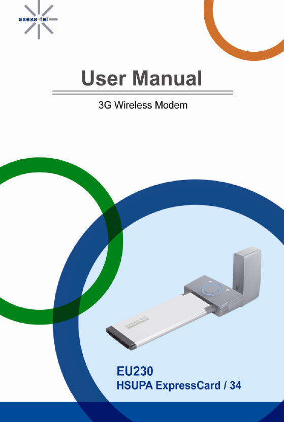
Thank you for purchasing the Axesstel EU230 ExpressCard
®34 (the Card). This user
manual will help you setup, configure and outline best practices for maximizing your
wireless home network performance with the Card.
The EU230 ExpressCard
®34 leverages WCDMA 3G networks to allow mobile
professionals to maintain productivity with secure, high speed access to email, the
Internet, data intensive files and multi-media streaming. SMS messaging enable
users to stay connected to colleagues, customers and family.
EU230 allows for quick and easy connectivity to a laptop PC equipped with
ExpressCard®34 interface or USB interface, providing broadband data access from
the home, office or while working remotely. Backward compatibility ensures services
in GSM/GPRS and EDGE coverage areas, while internal receive diversity antennas
maximize coverage range and data throughput. The slim and compact EU230
ExpressCard®34 provide busy professionals with the versatility to stay productive and
connected virtually anywhere, anytime from the home, office or while traveling.
FEATURES
1. PC-Based AxessManager Software
2. Color LED with Status Indicators
3. Receive Diversity for Maximum Range and Throughput
4. Text Messaging through GSM
5. Short Message Service
6. USB 2.0 adaptor
SAFETY PRECAUTIONS
1. Avoid placing the Card in a dusty location, or near a source of gas or fire.
2. Don't Shake, hit or drop the Card.
3. To clean the outside of the Card, use only a soft, dry cloth. The chemicals in
alcohol, benzene or acetone can damage the surface of the Card.
4. Do not twist or pull the Mini-B USB Cable.
5. Do not disassemble the Card.
6. Do not place the Card near water, for example, near a bathtub, sink, wet
basement, or swimming pool.
3
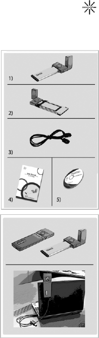
CHECKING THE PARTS
Once you have unpacked your product package, make sure that you have all the
parts shown below. If any piece is missing or broken, please call your customer
service.
1. Main Unit
2. USB adapter jacket
3. USB Data Cable
4. User Manual
5. CD Package for Win98/ME/NT
GETTING STARTED
Before you can begin using the Card, you must:
Ø Install the Card enabling software and driver.
Ø Have an activated and valid SIM card
CONNECTING YOUR CARD TO THE PC
This Card operates by receiving DC power from your PC.
Card installation ExpressCard®34 interface
1. Remove the Card jacket
2. Insert the Card to the ExpressCard®34 slot of
your PC. Make sure that the LED button faces upward.
Card installation USB interface
1. Insert the Card into USB jacket
2. Connect the small end of provided USB cable to the jacket
3. Connect the USB cable to your PC.
4
INSTALLING THE MODEM SOFTWARE
System Requirements
The system requirements for using this software are summarized below:
(1) Recommended Specifications
CPU: Pentium III 550MHz or higher, IBM PC-Compatible
RAM: 256MB or more
VGA: Video card with1024 I 768 resolution and 65536 or more colors
HDD: 200MB or more hard disk space
Others: CD-ROM Drive or DVD Drive
OS: Microsoft Windows 2000 or higher (Compatible with Vista version)
(2) Minimum Specifications
CPU: Pentium II 300MHz or higher, IBM PC-Compatible
RAM: 128MB or more
VGA: Video card with1024 I 768 resolution and 65536 or more colors
HDD: 100MB or more hard disk space
Others: CD-ROM Drive or DVD Drive
OS: Microsoft Windows 2000 or higher
(3) CD Package for Win 98/ME/NT
If O/S version of your PC is Windows 98/ME/NT, you should use CD Package for
installation of USB Driver and AxessManager.
Installing the USB Driver and AxessManager
The entire process will take approximately 5 minutes to complete.
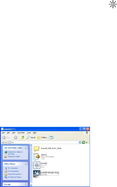
Step 1: After inserting the Card to the PC port the above window will appear. Click
“Axesstel Manager Setup.exe” to install AxessManager.
Note: If Windows OS auto-play feature is not available and you don’t see the pop-
up window in step 1, click on “Start” then “My Computer” to see the virtual
drive associated with the Card. Double-click on that drive to see the pop-up
window shown in step 1
5
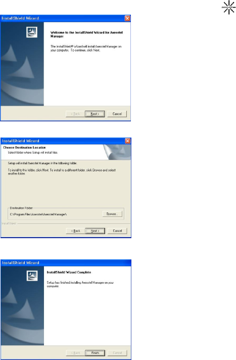
Step 2: Click “Next” to continue
Step 3: Click “Next” to continue
Step 4: Click Finish to complete
installation of AxessManager
6
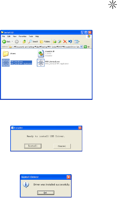
Step 5: Click Axesstel Driver Setup folder and select “Install 32” folder
*If you use 64bit OS, please run “MSP_Install64.exe” under “Install 64” folder.
Step 6: Click MSP_Install.exe to install USB Driver
The following screen will appear
Step 7: Click Install and make sure the driver was installed successfully.
7
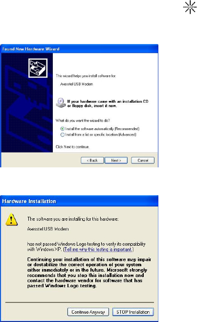
Step 8: After finishing driver file copy, the Card will change to Modem mode
from CD ROM Mode. Axesstel USB Mode will be detected on your PC. Sel ect
Next to install USB Driver
Step 9: Select Continue Anyway
8
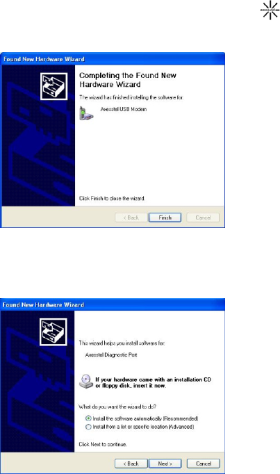
Step 10:.Click Finish to complete the process
Step 11: Axesstel Diagnostic Port will be detected on your PC. Select Next
to install USB Driver
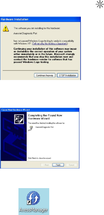
9
Step 12: Select Continue Anyway.
Step 13: Click Finish to complete the process. After this step you can begin to
use AxessManager
Once finished the installation, AxessManager SW utility will appear as a
short cut icon in Window.
10
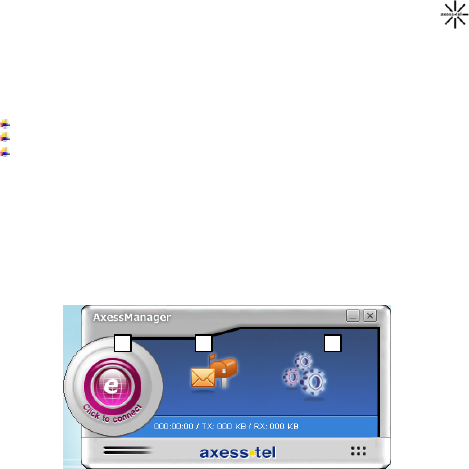
GETTING TO KNOW YOUR MODEM
AxessManager GUI
AxessManager is a SW utility that allows the administration of your Card. You use
AxessManager to:
Initiate data sessions
Receive and send SMS messag es
Customize features and options
1. Setting Button: Change options of your Card such as SMS setting, APN setting,
etc…
2. Connection Button: Initiate or stop a data session to connect to Internet via your
operator’s network
3. SMS Managers: Configure and manage your Inbox, templates etc...
3
1
2
11
AxessManager Operation Guide
1. Getting Started
When the PC and the Card are connected, AxessManager allows you to browse
Internet, modify modem configurations and text messaging. In addition, you can
perform management tasks for device numbers such as adding, modifying and
deleting them, and you can write messages in your PC and send them to your modem.
AxessManager provides the following 3 action-buttons that lead to corresponding
menus:
Internet Connection: Connection button allows you to connect to the internet
through your service provider.
SMS Manager: You can download the Inbox, Outbox, and Draft Box messages
in your Card to your PC and edit them, or upload newly created messages to
your modem and send them to others.
Settings: You can manage modem settings
1.1. Basic User Interface
1. Connect/Disconnect Button: Used to Connect/Disconnect PC and Device.
2. SMS Manager: when you click SMS Manager icon, the Sub Menu is displayed in
the tree structure
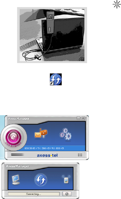
1.2. Connecting/Disconnecting Your Card to/From the PC
Connecting
1. Connect your PC with the Card by inserting it to your PC ExpressCard34
interface or using the supplied cable. Insert the Card or the cable firmly to the
modem until it clicks into place.
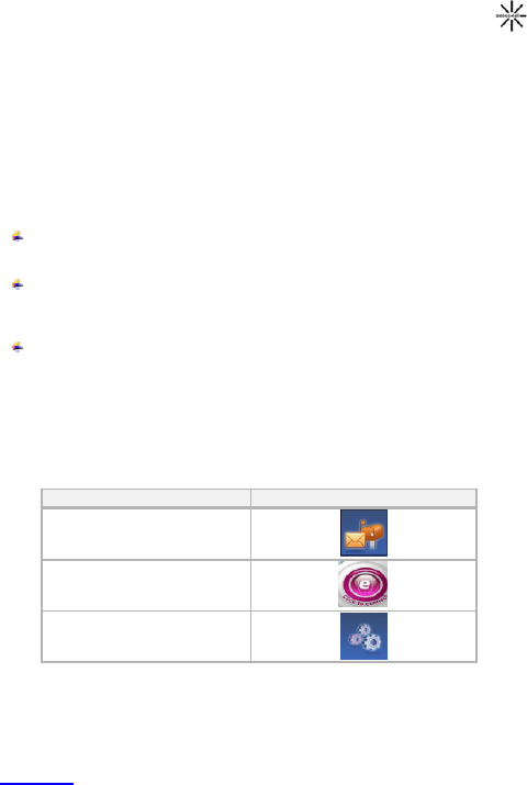
Name Image Button
SMS Manager
Connection
Settings
12
1. Click the icon on your desktop to run the AxessManager Program.
Axesstel Manager.lnk
2. Click the Connect/Disconnect button. Note that a connection profile needs to be
defined and selected before using the Connect/Disconnect button. Please refer to
the section “Add Connect Item” below for more information. When the connection
is successful, you can use the AxessManager program.
13
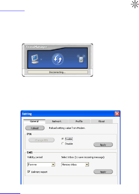
Disconnecting
1. Click the Connect/Disconnect button after finishing your job. The connection is
discontinued and the active Connect/Disconnect button is changed to the
disabled status.
2. To exit the program after finishing the job, click the “X” button at top right of the
program window.
3. Remove the Card from your PC or disconnect the cable from PC and Card.
2. Device Setting
Click the Setting button on the main screen of the program to open the following
dialog, where you can specify values for many items needed to set up your
modem. The following screen will appear.
2.1. General
Reload button allows you to reset the Card setting to default factory setting.
PIN setting sub-menu allows you to enable or disable the feature. Check with
your service provider before you attempt to change the PIN value or enable
this feature. Click the Apply button to confirm your new selection.
14
SMS setting sub-menu: use this function to (i) set the timer for the message to
remain in your Card and (ii) select the location where incoming messages will
be stored. If you select the location as “SIM inbox”, all incoming messages to
your number are stored in the memory of your SIM card. If you move your SIM
card to another device, the messages will follow. If you select “Memory Inbox”
the messages are stored in the Card.
Drop-down window in each setting allows you to choose the right option. Click
the Apply button to confirm your new selection.
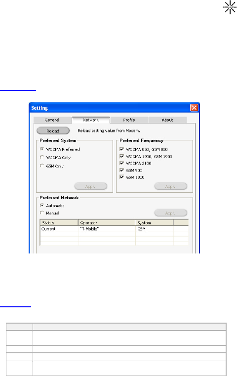
2.2. Network
You can change the preferred network setting by using the network setting sub-
menu. Note that changing these parameters will affect the functionality and
performance of the Card and your Internet connection. Consult your service
provider before making any changes in this sub-menu.
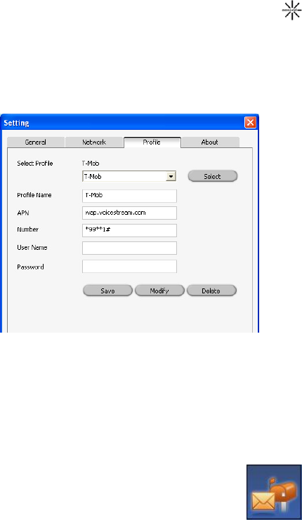
2.2. Profile
A short, functional description for each button on the Setting is provided below.
Button
Description
Save Allows you to save changes made to an existing entry in your
Connection Profile
Modify Allows you to modify existing 'Profile' settings.
Delete Allows you to delete an existing entry in your Connection Profile
Select Allows you to view and select from a list of modems currently
available for connection.
15
Add New Connection Profile
To add new profile, simply enter the information into each connection parameter
then click Save button.
(1) Profile Name: Enter the name to be displayed on the 'Connect Item' list.
(2) Number: Specify the device number to which modem will connect.
(3) User Name: If required, enter the user ID for the network provider.
(4) Password: Enter the password for the user name.
Delete Profile
Select the 'Profile Item' you want to erase from the list and click Delete.
Modify Profile
Select the 'Profile Item' you want to modify from the list. The parameters associated
with this profile will be filled in. Make the necessary changes and click Modify. See
‘Add New Connection Profile” for detailed descriptions about the settings.
Once you are satisfied with all changes in Setting click the ‘X’ button to return to the
main window.
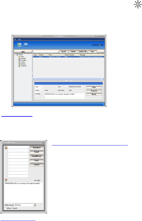
3. SMS Manager
SMS Manager is composed of Inbox for keeping received messages,
Outbox for saving messages that have been sent out, Draft Box for
saving messages that have not yet been sent and Saved Box for
keeping important messages in the Inbox. You can directly send out
messages from your PC to your device, or download it from device
to PC for more convenient management.
16
3.1. Inbox/SIM Inbox Manager
Both Inbox and SIM Inbox Manager offer same features. The difference is only the
location where the messages were stored. Refer to section 2.1 for more details about
storing incoming messages.
With Inbox Manager, you can reply to, forward, or delete selected messages.
1. Inbox List View
(1) By default, Inbox List View shows all Inbox messages saved in the device.
(2) The details of the Inbox message selected from Inbox List View is displayed in the
Preview window at bottom.
(3) You can delete the messages displayed in Inbox List View. (You cannot add.)
2. Preview Window & Reply/Forward (Send)
(1) The content of the Inbox message selected from
Inbox List is displayed in the Preview window at
bottom.
(2) When you click the Reply button in the Preview
window, a new window pops up for you to edit the
message and send it to the sender. The device
number is populated in the Reply function.
(3) When you click the Forward button in the Preview
window, a new window pops up for you to edit the
message and send it to the another person. The
message content is included in the Forward function
(4) You can send a message to multiple persons. Just
type in each device number in a separate line
(5) You can also compose and send a new message
from the Preview Window.
3. Delete Inbox Data
Select the data to delete and press the Delete key.

17
To delete multiple data simultaneously, select them with your mouse while pressing
down the Shift or Ctrl key and then press the Delete key. The selected Inbox data is
deleted at once from the device.
The deleted Inbox data cannot be restored.
4. To PC
???.
3.2. Saved box Manager
To use Saved Box Manager, click the Saved Box text at the left of SMS Manager.
With Saved Box Manager, you can reply to, forward, or delete selected messages.
1. Saved Box List View
(1) By default, Saved Box List View shows all Saved Box messages saved in the
modem.
(2) The details of the Saved Box message selected from Saved Box List View is
displayed in the Preview window at bottom.
(3) You can delete the messages displayed in Saved Box List View. (You cannot
add.)
2. Preview Window & Reply/Forward (Send)
(1) The details of the Saved Box message selected from Saved Box List View is
displayed in the Preview window at bottom.
(2) When you click the Reply button in the Preview window, a new window pops up
for you to edit the message and send it to the sender.
(3) When you click the Forward button in the Preview window, a new window pops up
for you to edit the message and send it to the another person.
(4) You can send a message to multiple persons.
3. Delete Saved Box Data
Select the data to delete and press the Delete key on the keyboard. To delete multiple
data simultaneously, select them with your mouse while pressing down the Shift or
Ctrl key and then press the Delete key. The selected Saved Box data is deleted at
once from the modem.
The deleted Saved Box data cannot be restored.
4. To PC
???.
3.3. Outbox Manager
To use Outbox Manager, click the Outbox icon With Outbox Manager, you can
forward, modify, or delete selected messages in Outbox.
1. Outbox List View
(1) By default, Outbox List View shows all Outbox messages saved in the modem.
(2) The details of the Outbox message selected from Outbox List View is displayed in
the Preview window at bottom.
(3) You can delete the data displayed in Outbox List View
2. Preview Window & Forward (Send)

18
(1) The detail of the Outbox message selected from Outbox List View is displayed in
the Preview window at bottom.
(2) To write a new message, click the Send button in the Preview window. A new
window pops up in which you can write a new message and send it to others.
(3) When you click the Forward button in the Preview window, a new window pops up
for you to edit the message and send it to the another person.
(4) You can send a message to multiple persons.
(5) Type in the device number and click the search button to add to the recipients' list.
3. Delete Outbox Data
Select the data to delete and press the Delete key on the keyboard. To delete multiple
data simultaneously, select them with your mouse while pressing down the Shift or
Ctrl key and then press the Delete key. The selected Outbox data is deleted at once
from the modem
The deleted Outbox data cannot be restored
4. To PC
???.
3.4. Draft Box Manager
To use Draft Box Manager, click the Draft Box icon.
With Draft Box Manager, you can forward, or delete selected messages in Draft Box.
1. Draft Box List View
(1) By default, Draft Box List View shows all Draft Box messages saved in the modem.
(2) The details of the Draft Box message selected from Draft Box List View is
displayed in the Preview window at bottom.
(3) You can delete the data displayed in Draft Box List View.
2. Preview Window & Forward (Send)
(1) The details of the Draft Box message selected from Draft Box List View is
displayed in the Preview window at bottom.
(2) To write a new message, click the “New” button in the Preview window, or double
click an empty field in the Draft Box List. A new window pops up in which you can
write a new message and send it to others.
(3) When you click the Forward button in the Preview window, a new window pops up
for you to edit the message and send it to the another person.
(4) You can send a message to multiple persons.
(5) Type in the device number and click the search button to add to the recipients' list.
3. Delete Draft Box Data
Select the data to delete and press the Delete key on the keyboard. To delete multiple
data simultaneously, select them with your mouse while pressing down the Shift or
Ctrl key and then press the Delete key. The selected Draft Box data is deleted at once
from the modem.
The deleted Draft Box data cannot be restored.
4. To PC
The Draft Box List View is updated with the Draft Box messages currently saved in
the modem.
19
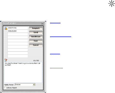
3.5. Send
To send a new message, press New button the Preview window.
A new window will pop up. There are 4 buttons in the Send window.
1. Send
Send the message directly to the recipients
through the modem.
2. Send & Save
Send the message directly to the recipients
through the modem. The message is also saved
in the Outbox in the modem
3. Save
This button does not send the message.
Message is saved in the Draftbox for later use.
4. Cancel
This button cancels the current operation and
returns to the SMS manager menu.
20
Miscellaneous
SPECIFICATIONS
Tri-band UMTS: 2100/ 1900/ 850 MHz
(Band I/ II/V)
Frequency Range Quad-band GSM / GPRS / EDGE: 850 / 900
/ 1800 / 1900 MHz
Channel Bandwidth WCDMA 5 MHz
External appearance
(mm) Express Card: 125.2 x 46 x 13
Express Card + USB Adaptor: 144.1 x 46 x
13
Weight Express Card: 45g, total 70g.
Sending output 3gpp UE Power Class 3 (+24 dBm)
GSM Power Class 4 (2W) (850/900 MHz)
GSM Power Class 1 (1W) (1800/1900 MHz)
EDGE Power Class E2 (+27dBm in 850/900
bands, +26dBm in 1800/1900 bands)
Temperature of operation
Relative humidity
-10 ~ +55 degrees Celsius
5% ~ 90%
AXT_v4. 1
SAR INFORMATION
THIS MODEL DEVICE MEETS THE GOVERNMENT’S
REQUIREMENTS FOR EXPOSURE TO RADIO WAVES
Your wireless device is a radio transmitter and receiver. It is designed and
manufactured not to exceed the emission limits for exposure to radiofrequency (RF)
energy set by the Federal Communications Commission of the US Government.
These limits are part of comprehensive guidelines and establish permitted levels of
RF energy for the general population.
The guidelines are based on standards that were developed by independent scientific
Organizations through periodic and thorough evaluation of scientific studies. The
standards include a substantial safety margin designed to assure the safety of all
persons, regardless of age and health. The exposure standard for wireless mobile
devices employs a unit of measurement known as the Specific Absorption Rate, or
SAR. The SAR limit set by the FCC is 1.6 W/kg. *
Tests for SAR are conducted with the device transmitting at its highest certified power
level in all tested frequency bands. Although the SAR is determined at the highest
certified power level, the actual SAR level of the device while operating can be well
below the maximum value. This is because the device is designed to operate at
multiple power levels so as to use only the power required to reach the network. In
general, the closer you are to a wireless base station antenna, the lower the power
output. Before device is available for sale to the public, it must be tested and certified
to the FCC that it does not exceed the limit established by the government adopted

21
requirement for safe exposure. The tests are performed in positions and locations
(e.g., at the ear and worn on the body) as required by the FCC for each model.
The highest FCC SAR value for this device when tested for use at the when worn on
the body, as described in this user guide, is 0.92 W/Kg . (Body-worn measur ements
differ among device models, depending upon available accessories and FCC
requirements). While there may be differences between the SAR levels of various
devices and at various positions, they all meet the government requirement for safe
exposure.
The FCC has granted an Equipment Authorization for this device with all reported
SAR levels evaluated as in compliance with the FCC RF exposure guidelines. SAR
information on this model device is on file with the FCC and can be found under the
Display Grant section of ttp://www.fcc.gov/oet/fccid after searching on FCC ID:
PH7EU230.
Additional information on Specific Absorption Rates (SAR) can be found on the
Cellular Telecommunications Industry Association (CTIA) web-site at http://www.wow-
com.com. * In the United States and Canada, the SAR limit for device used by the
public is 1.6 watts/kg (W/kg) averaged over one gram of tissue. The standard
incorporates a substantial margin of safety to give additional protection for the public
and to account for any variations in measurements.
SAFETY INFORMATION FOR RF EXPOSURE
Body worm operation
This device was tested for typical body-worn operations with the back of the device
kept 5 mm. from the body. To maintain compliance with FCC RF exposure
requirements. The use of accessories that do not satisfy these requirements may not
comply with FCC RF exposure requirements, and should be avoided.
Safety Information
1. SAFETY INFORMATION FOR FIXED WIRELESS TERMINALS POTENTIALLY
EXPLOSIVE ATMOSPHERES
Turn your device OFF when in any area with a potentially explosive atmosphere and
obey all signs and instructions. Sparks in such areas could cause an explosion or fire
resulting in bodily injury or even death.
2. INTERFERENCE TO MEDICAL DIVICES
Certain electronic equipment may be shielded against RF signal from you wireless
device. (pacemakers, Hearing Aids, and so on) Turn your device OFF in health c are
facilities when any regulations posted in these areas instruct you to do so. RF signals
may affect improperly installed or inadequately shielded electronic system in motor
vehicles.
3.EXPOSURE TO RF ENERGY
Use only the supplied or an approved replacement antenna. Do not touch the antenna
unnecessarily when the device is in use. Do not move the antenna close to, or
couching any exposed part of the body .
FCC Compliance Information
This device complies with Part 15 of FCC Rules.
Operation is subject to the following two conditions:
(1) This device may not cause harmful interference, and
(2) This device must accept any interference received including interference that may
cause undesired operation.
22
U.S.A.
U.S.FEDERAL COMMUNICATIONS COMMISSION
RADIO FREQUENCY INTERFERENCE STATEMENT
INFORMATION TO THE USER
NOTE : This equipment has been tested and found to comply with the limits for a
Class B digital device pursuant to Part 15 of the FCC Rules. These limits are
designed to provide reasonable protection against harmful Interference in a
residential installation This equipment generates, uses, and can radiate radio
frequency energy and, if Not installed and used in accordance with the instructions,
may cause harmful Interference to radio communications.
However, there is no guarantee that interference will not occur in a particular
Installation.
If this equipment does cause harmful interference to radio or television reception,
which can be determined by turning the equipment off and on, the user is encouraged
to try to correct the interference by one or more of the following measures:
*- Reorient or relocate the receiving antenna. Increase the separation between the
equipment and receiver.
*- ?Connect the equipment into an outlet of a circuit different from that to which the
receiver is connected.
*- ?Consult the dealer or an exp erienced radio/TV technician for assistance.
Changes or modification not expressly approved by the party responsible for
Compliance could void the user’s authority to operate the equipment. Connecting of
peripherals requires the use of grounded shielded signal cables
Europe
SAR Limits For Safe Exposure To Radio Waves
Your HSUPA express card is a radio transceiver (transmits and receives). It
does not exceed the safe limits of radio wave exposure established by
international guidelines. These safety guidelines are well within safety
margins designed to assure the protection of all persons, regardless of age
or health.
˙ The exposure guidelines for mobile devices utilize a unit of
measurement known as the Specific Absorption Rate or SAR. In Europe,
the SAR limit guideline stated by the scientific organization ICNIRP is 2.0
watts/kilogram (W/kg) averaged over ten grams of tissue. The U.S.
Federal Communications Commission and Industry Canada and the
IEEE (Institute of Electrical and Electronics Engineers) requirements set
an SAR limit of 1.6 W/kg averaged over one gram of tissue.
˙ SAR tests are performed in body positions with the device transmitting at
its highest certified power level in all test frequency bands. Actual device

23
SAR operating levels may be below the maximum value because the
device is designed to use only that power necessary to reach a network.
That amount varies depending on base station proximity and other
factors.
˙ There may be different SAR values depending on the mode, all modes
are designed to meet radio wave requirements. The highest CE body
SAR value under the ICNIRP guidelines for use of this device by
the head is 1.86 W/kg.
Note that different SAR values may result from use of device accessories
and enhancements. SAR values may vary depending on regional
measuring and testing standards and the network band.

24