Axesstel MU430 GSM/ WCDMA Gateway with Wi-Fi User Manual User ID and Password
Axesstel Inc GSM/ WCDMA Gateway with Wi-Fi User ID and Password
Axesstel >
User manual

1
Important Notice
Due to the nature of wireless communications, transmission and reception of data
can never be guaranteed. Data may be delayed, corrupted (i.e., have errors) or be
totally lost. Although significant delays or losses of data are rare when wireless
devices such as the Axesstel modem are used in a normal manner with a well-
constructed network, the Axesstel modem should not be used in situations where
failure to transmit or receive data could result in damage of any kind to the user or
any other party, including but not limited to personal injury, death, or loss of
property. Axesstel accepts no responsibility for damages of any kind resulting from
delays or errors in data transmitted or received using the Axesstel modem, or for
failure of the Axesstel modem to transmit or receive such data.
Safety and Hazards
Do not operate the Axesstel modem:
¾ In areas where blasting is in progress
¾ Where explosive atmospheres may be present
¾ Near medical equipment
¾ Near life support equipment, or any equipment that may be susceptible to
any form of radio interference. In such areas, the Axesstel modem MUST
BE POWERED OFF. The Axesstel modem can transmit signals that could
interfere with this equipment.
Do not operate the Axesstel modem in any aircraft, whether the aircraft is on the
ground or in flight. In aircraft, the Axesstel modem MUST BE POWERED OFF.
When operating, the Axesstel modem can transmit signals that could interfere
with various onboard systems.
Note: Some airlines may permit the use of cellular phones while the aircraft is on
the ground and the door is open. The Axesstel modem may be used at this time.
The driver or operator of any vehicle should not operate the Axesstel modem
while in control of a vehicle. Doing so will detract from the driver or operator’s
control and operation of that vehicle. In some states and provinces, operating
such communications devices while in control of a vehicle is an offence.

2
Limitation of Liability
The information in this manual is subject to change without notice and does not
represent a commitment on the part of Axesstel. AXESSTEL SPECIFICALLY
DISCLAIMS LIABILITY FOR ANY AND ALL DIRECT, INDIRECT, SPECIAL,
GENERAL, INCIDENTAL, CONSEQUENTIAL, PUNITIVE OR EXEMPLARY
DAMAGES INCLUDING, BUT NOT LIMITED TO, LOSS OF PROFITS OR
REVENUE OR ANTICIPATED PROFITS OR REVENUE ARISING OUT OF THE
USE OR INABILITY TO USE ANY AXESSTEL PRODUCT, EVEN IF AXESSTEL
HAS BEEN ADVISED OF THE POSSIBILITY OF SUCH DAMAGES OR THEY
ARE FORESEEABLE OR FOR CLAIMS BY ANY THIRD PARTY.
Notwithstanding the foregoing, in no event shall Axesstel aggregate liability arising
under or in connection with the Axesstel product, regardless of the number of
events, occurrences, or claims giving rise to liability, be in excess of the price paid
by the purchaser for the Axesstel product.

3
Table of Contents
1. Introduction ……………………………………….…...……….. 5
2. Product Overview …………………………….………...…...… 7
3. Knowing your Modem ……………………….……..………… 10
Package Contents ………………………………………………. 10
Modem Interface ………………………………………………… 10
System Components ……………………………………………. 13
4. Connecting and Configuring your Modem ….………..…… 15
5. Using USB with your Modem ……………….……..………… 19
6. Connection using Ethernet (RJ45) Ports ….………….…… 24
Configuring Your PC …………………………….……………… 24
Configuring Ethernet Connection ……………….……………... 26
7. AxessManager Operational Guide ……….……………..…...28
Using the Main Window ……………………………....………… 28
Using the Menu Window ……………………………………..…. 31
8. Web Manager User Interface …………….…………………... 35
Basic Settings ………………………….……….………………… 37
Configuring the Wireless Network Settings ………..…………...38
Router Setup ……………………………………….…….……….. 40
Configuring Port Forwarding ……………………….……………. 43
WAN Setup …………………………………………….….………. 45
9. Troubleshooting ………………………………………………... 47
10. Technical Specification ……………………………………… 51

4
Introduction
Thank you for purchasing the Axesstel MU430(3.75G Gateway). This user manual
will help you setup, configure and outline best practices for maximizing your
wireless home network performance with the Modem. Please be sure to read
through this User Manual completely, and pay special attention to the section
entitled “Placement of your Modem for Optimal Performance” on page 2.
Placement of your Modem for Optimal Performance
Your wireless connection will be stronger the closer your computer is to your
Modem. Typical indoor operating range for Wi-Fi wireless devices is between 100
and 200 feet. For HSUPA operation, a line-of-sight with the radio base station is
preferred and yields the strongest signal strength.
In the same way, your wireless connection and performance will degrade
somewhat as the distance between your Modem and connected devices
increases, as well as between the Modem and the radio base station. This may or
may not be noticeable to you. As you move farther from your Modem, connection
speed may decrease. Factors that can weaken signals simply by getting in the
way of your network’s radio waves are metal appliances or obstructions, and walls.
Note: While some of the items listed below can affect network performance, they
will not prohibit your wireless network from functioning; if you are concerned that
your network is not operating at its maximum effectiveness, this checklist may
help.
1. Modem Placement
Place your Modem, the central connection point of your network, as close as
possible to windows or in rooms at the outer side of your house. If you also use
the Wi-Fi feature of the Modem, it should be placed near the center of your
wireless network devices.
To achieve the best wireless network coverage:
• Ensure that your Modem’s networking antennas are parallel to each other,
and are positioned vertically (toward the ceiling). If your Modem itself is
positioned vertically, point the antennas as much as possible in an
upward direction.

5
• In multistory homes, place the Modem on an upper floor.
• Try not to place the Modem near a cordless phone (MU430 only).
2. Avoid Obstacles and Interference
Avoid placing your Modem near devices that may emit radio “noise,” such as
microwave ovens. Dense objects that can inhibit wireless communication include:
• Refrigerators
• Washers and/or dryers
• Metal cabinets
• Large aquariums
• Metallic-based, UV-tinted windows
If your wireless signal seems weak in some spots, try to move the Modem to
another location while observing the signal strength indicator. Since you may not
know the location of an WCDMA radio base station serving your Modem, try to
call your service provider and ask for the nearest base station of your home. Try
placing the Modem closest and unobstructed to that base station.

6
Product Overview
In minutes you will be able to connect your computers to the Internet, share your
Internet connection and network your computers. The following is a list of features
that make your new Axesstel HSUPA Modem an ideal solution for your home or
small office network. Implementation of these features depends on the particular
service provider and account features you have chosen.
Some features described in this manual may not be supported by your service
provider or may not be available with your network account. For details of the
services and accounts available, contact your service provider.
WCDMA 3G services
The Modem operates over the WCDMA 3G technology that provides a variety of
connectivity features, depending on your service provider and account:
¾ HSDPA Supports Internet connections with data rates up to 7.2 Mbps
(downlink from the network) and 384Kbps (Uplink to the network). Actual
speed depends on the network conditions.
¾ HSUPA Provides up-link performance of up to 5.76Mbit/s. Actual speed
depends on the network conditions.
Once the connection is established, you can open your browser and connect to
any web site that is accessible through the Internet, or access other Internet
services (such as email).
The connection is “active” when data transmission is occurring. If data
transmission stops for a period of time (determined by the network), the
connection becomes “dormant”; see page 26.
Plug-and-Play
Each Modem has been provisioned at the factory for use with a particular service
provider. This sets the Modem to use particular radio channels and enables
services specific for that provider. Although the Modem comes with drivers and
enabling software, you don’t have to install and use them if you simply want to
connect to the Internet, assuming that your Modem has been activated with the
network (The process of setting up your account is called activation. Activation
involves action by the service provider and configuration of the Modem.)

7
Once the Modem has been activated, simply connect your computer with the
Modem using the provided Ethernet (RJ-45) cable and you are ready to use the
Internet. If you choose to install the driver and its enabling software (the
AxessManager), you will have more controls of the Modem performances and
settings.
Works with Both PCs and Mac® Computers
The Modem supports a variety of networking environments including Mac OS®
9.x, X v10.x, AppleTalk®, Linux®, Windows® 98, Me, NT®, 2000, and XP, and
others. All that is needed is an Internet browser and a network adapter that
supports TCP/IP (the standard language of the Internet).
Top-View LED Display
Lighted LEDs on the top of the Modem indicate which functions are in operation.
You’ll know at-a-glance whether your Modem is in HSUPA or HSDPA mode,
connected to the Internet, and in Wi-Fi or Ethernet operation. This feature
eliminates the need for advanced software and status-monitoring procedures.
Web-Based Advanced User Interface
You can set up the Modem’s advanced functions easily through you’re
AxessManager web browser, without having to install additional software onto the
computer. There are no disks to install or keep track of and, best of all, you can
make changes and perform setup functions from any computer on the network
quickly and easily.
NAT IP Address Sharing
Your Modem employs Network Address Translation (NAT) to share the single IP
address assigned to you by your Internet Service Provider while saving the cost of
adding IP addresses to your Internet service account.
Integrated 10/100 4-Port Switch
The Modem has a built-in, 4-port network switch to allow your wired computers to
share printers, data and MP3 files, digital photos, and much more. The switch
features automatic detection so it will adjust to the speed of connected devices.
The switch will transfer data between computers and the Internet simultaneously
without interrupting or consuming resources.
Support for VPN Pass-Through
If you connect to your office network from home using a VPN connection, your
Modem will allow your VPN-equipped computer to pass through the Modem and

8
to your office network.
Built-In Dynamic Host Configuration Protocol (DHCP)
Built-In Dynamic Host Configuration Protocol (DHCP) on-board makes for the
easiest possible connection of a network. The DHCP server will assign IP
addresses to each computer automatically so there is no need for a complicated
networking setup.
Integrated 802.11g Wireless Access Point
802.11g is an exciting new wireless technology that achieves data rates up to
54Mbps, nearly five times faster than 802.11b.
MAC Address Filtering
For added security, you can set up a list of MAC addresses (unique client
identifiers) that are allowed access to your network. Every computer has its own
MAC address. Simply enter these MAC addresses into a list using the Web-Based
Advanced User Interface and you can control access to your network.
9
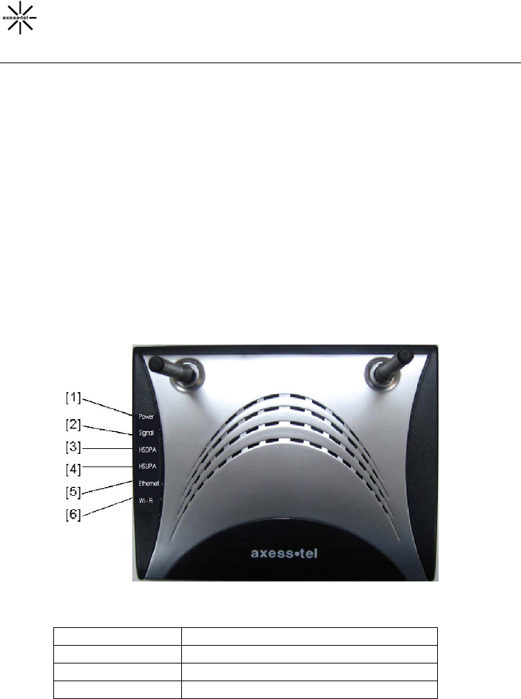
Knowing your Modem
Packages Contents
• HSUPA Modem
• User Manual
• Software CD with User Manual
• RJ45 Ethernet Networking Cable
• USB Cable
• Power Supply and Battery
Modem Interfaces
The Modem has been designed to be placed on a desktop or wall mounted. All of
the cables exit from the front of the Modem for better organization and utility. The
LED indicators are easily visible on the top of the Modem to provide you with
information about network activity and status.
1. Power LED
OFF Modem is OFF
Solid Green Battery connected & fully charged
Solid Orange Battery connected & half charged
Solid Red Battery connected & low
10
Blinking Green Battery/Charger connected &
charging
Blinking Red Battery connected & charging error
2. Signal Strength LED
This LED indicates the signal strength of the network serving your Modem.
OFF No signal
Solid Green Strongest level
Solid Orange Medium level
Solid Red Low signal
3. HSDPA LED
This LED informs you that the Modem is connected to a WCDMA network and
passed through the user/password validation.
OFF Modem is in idle state or dormant
state
Solid Green Modem is in conversation state of
HSUPA, HSDPA
Blinking Green Modem is in conversation state of
WCDMA,2G
4. HSUPA LED
This LED informs you that the Modem is tuned to a HSUPA wireless network.
Normally your Modem is programmed to search and use HSUPA network. If
unavailable, the Modem will try to search for an other network. Please check
with your Service Provider for default setting.
OFF others
Solid Green HSUPA
5. Ethernet LED
This LED indicates that there are computers connecting to your Modem via one
of the RJ-45 ports. When the LED is blinking, it indicates that there are activities
(data passed through).
11
OFF No RJ-45 (Ethernet) connection
Solid Green At least one of the RJ-45 ports in use
Blinking Green Active data passed through the ports
6. Wi-Fi LED (MU430 only)
This LED indicates that your Modem is setup to have Wi-Fi capability. When the
LED is blinking, it indicates that there are activities (data passed through).
OFF No Wi-Fi
Solid Green Wi-Fi network within Modem is activated
Blinking Green Active data passed through Wi-Fi
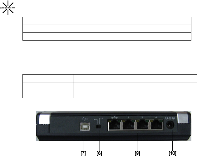
7. USB Connection to Computers
Connect your wired (non-wireless) computer to this port using the supplied USB
cable.
8. USB/RJ-45 Switch
This switch allows your Modem to connect with your computer via either USB
port or RJ-45 ports.
9. Connections to Computers (Wired Computer Ports)
Connect your wired (non-wireless) computers to these ports. These ports are
RJ45, 10/100 auto-negotiation, auto up-linking ports for standard UTP category
5 or 6 Ethernet cable. The ports are labeled 1 through 4.
10. Power Jack
Connect the included 5V DC power supply to this jack.
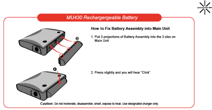
11. Rechargeable Battery (optional for MU430)
12
System components
Your Modem is just one part of a system designed to provide you with a wide
range of communication features. Every component of the system is needed to
enable these capabilities.
Your host computing device
Your notebook or PC hosts the Modem and runs the communication software:
your web browser or email application and Connection Manager—the Modem
enabling software.
You may also have other software on your computer that can be used wirelessly
with the Modem, such as: file transfer applications (FTP), chat or instant
messaging, a VPN (Virtual Private Network) client, client software for a corporate
server application.
The Modem
The Modem provides your computer with a connection to the
GSM/GPRS/EGDE/WCDMA
wireless network. Every
GSM/GPRS/EGDE/WCDMA
network operates on one of five radio
frequency bands
(850MHz, 900MHz, 1800MHz, 1900MHz and 2100MHz)
The Modem drivers and enabling software
Required to control, monitor, and manage your wireless connections, this includes
the AxessManager application and USB device driver.
The Modem comes with a CD containing this software:
¾ AxessManager application that you use to manage the Modem and

13
monitor your connections
¾ The USB device driver software that enables the Modem to work with
your computer’s operating system.
The USB driver and application software must be installed before you insert the
Modem for the first time if you choose to connect the Modem with your PC USB
port. AxessManager application is optional: you can install it at anytime or not
installing it altogether. Detailed instructions are provided in the following chapters.
A GSM/GPRS/EGDE/WCDMA service provider account
Companies that operate
GSM/GPRS/EGDE/WCDMA
networks and provide access to these
networks are called service providers. To use the Modem, you must have an
account with the service provider.
Each service provider has its own pricing options. There may be flat rate accounts,
which provide you a maximum number of minutes of network usage for a fixed
monthly fee. There may be accounts for which you are charged for network usage
by the minute or by the amount of data transmitted.
Your account may include a variety of other services such as SMS messaging.
Each Modem has been provisioned at the factory for use with a particular service
provider. This sets the Modem to use particular radio channels and enables
services specific for that provider.
The process of setting up your account is called activation. Activation involves
action by the service provider and configuration of the Modem.
The WCDMA wireless network
This is the worldwide infrastructure providing the radio coverage that allows you to
stay connected. Made up of radio towers and a variety of network switches,
routers, and servers, the network is an interconnection of many service providers.
Note: More information about WCDMA networks is available on the GSM core
development group web site, www.3gpp.org.
Note: Some service providers have coverage maps on their web sites.

14
Connecting and Configuring your Modem
Each Modem has been provisioned at the factory for use with a particular service
provider. This sets the Modem to use particular radio channels and enables
services specific for that provider.
MU430: Although the Modem comes with drivers and enabling software, you don’t
have to install and use them if you simply want to connect to the Internet through
the Ethernet (RJ-45) ports, assuming that your Modem has been activated with
the network. Simply connect your computer with the Modem using the provided
Ethernet (RJ-45) cable and you are ready to use the Internet.
However, if you want to connect to the Internet through USB port, you must install
AxessManager software.
If you choose to install the drivers and its enabling software (the AxessManager)
you will have more controls of the Modem performances and settings. You will
also have access to more advance features of the Modem such as Wi-Fi
configuration USB connection and password management.
This chapter provides the step-by-step process to install the AxessManager
connectivity software.
Install Software
Axesstel has provided our AxessManager software to make installing your Modem
a simple and easy task. You can use it to get your Modem up and running in
minutes. The AxessManager software requires that your Windows XP, or Vista
computer be connected directly to your Modem.
IMPORTANT: Run the installation software from the computer that is going to be
the main connection with the Modem.
DO NOT CONNECT THE MODEM AT THIS TIME.
Step 1 │ Run the Install Software
1.1. Shut down any programs that are running on your computer at this time.
1.2 Make sure you have the following items at the computer that is going to be
the main connection with the Modem. DO NOT CONNECT THE MODEM
AT THIS TIME.
• The Installation Software CD with User Manual
• The Modem

15
• The Modem’s Power Supply
• RJ45 Ethernet Networking Cable
1.3 Turn off any firewall or Internet-connection-sharing software on your
computer.
1.4 Insert the installation software CD into your CD-ROM drive. The Installation
screen will automatically appear on your screen within 15 seconds. If it does
not, select your CD-ROM drive from “My Computer” and double-click on the
file named “AxessManager.exe” on the CD-ROM.
16
Using USB with your Modem
The Modem has one USB Type B port to provide connectivity for computers
equipped with USB. If you choose to use the USB with your Modem, you first
need to install the provided USB device driver into your computer.
This chapter provides the step-by-step process to install the USB device driver.
IMPORTANT: Run the USB device driver installation from the computer that is
going to be the main connection with the Modem.
DO NOT CONNECT THE MODEM AT THIS TIME.
Step 1 │ Run the Setup Software
1.1. Shut down any programs that are running on your computer at this time.
1.2 Make sure you have the following items at the computer that is going to be
the main connection with the Modem. DO NOT CONNECT THE MODEM
AT THIS TIME.
• The Install Software CD with User Manual
• The Modem
• The Modem’s Power Supply
• USB Cable
1.3 Insert the Install software CD into your CD-ROM drive. Locate the folder
“Driver”. You will see two subfolders: “Install 32” and “Install 64”. For PC
with Windows Vista 64, use “Install 64”. Otherwise, use “Install 32”.
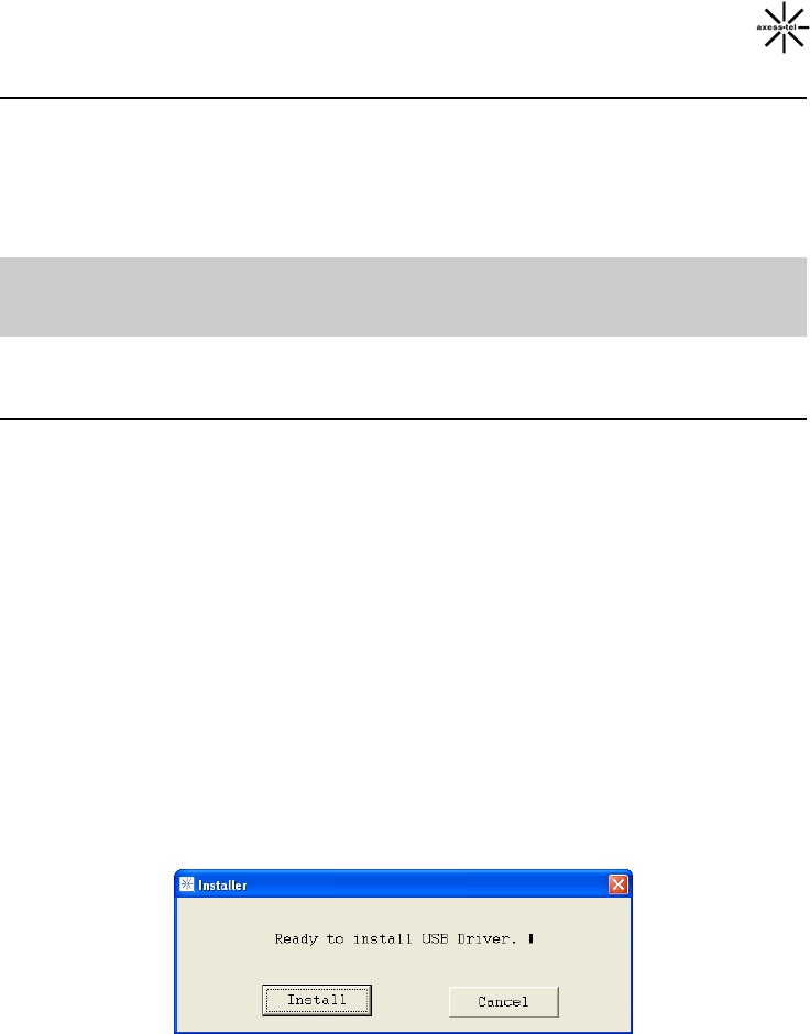
1.4 Press “MSP_Install.exe”. The following screen will appear. Select “Install”.
17
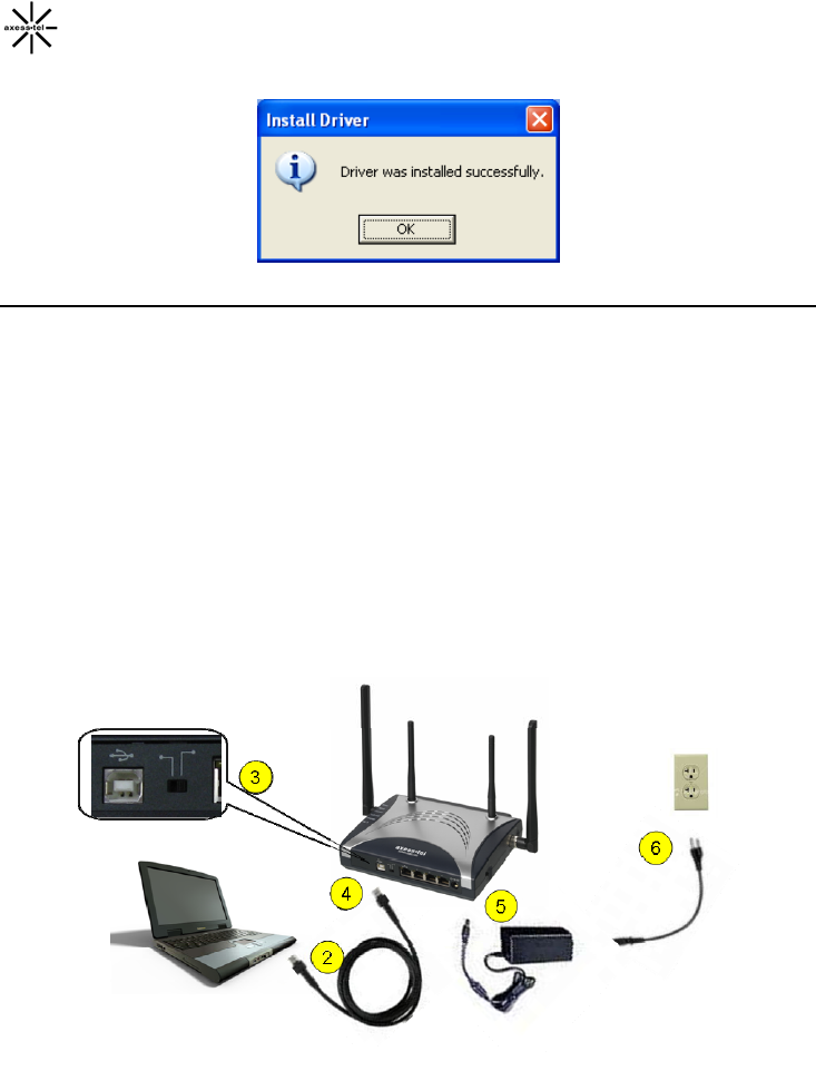
1.5 Click “OK”.
Step 2 │Connecting the Modem to your PC
2.1. Turn off both the HSPA modem and your PC.
2.2. Connect the included USB Cable to the USB port on your PC.
2.3. The Modem cable select switch, located between Ethernet and USB
connectors, should be set to USB.
2.4. Connect other end of the USB Cable to USB port on the Modem.
2.5. Connect the included Power Adapter to Power connector of HSPA modem.
2.6. Connect the other end of Power Adapter to an electrical outlet.
2.7. Power on HSPA modem.
18
Step 3 │Window Device Setup
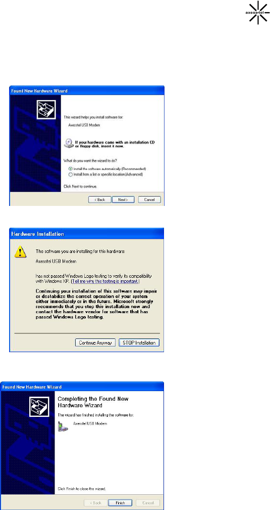
3.1 Power ON the PC. After the boot-up process, you will see “Found New
Hardware” screen appears. Select Next to install USB
3.2 Select “Continue Anyway”.
3.3 Press “Finish” to complete the process.
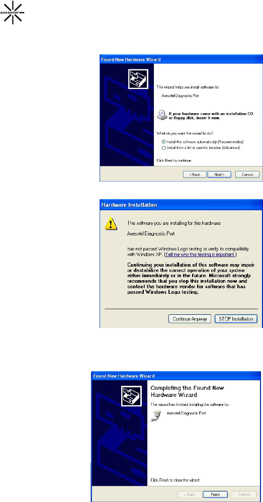
19
3.4 Axesstel Diagnostic Port will be detected on your PC. Select Next to
install.
3.5 Select “Continue Anyway”.
3.6 Press “Finish” to complete the process.
20
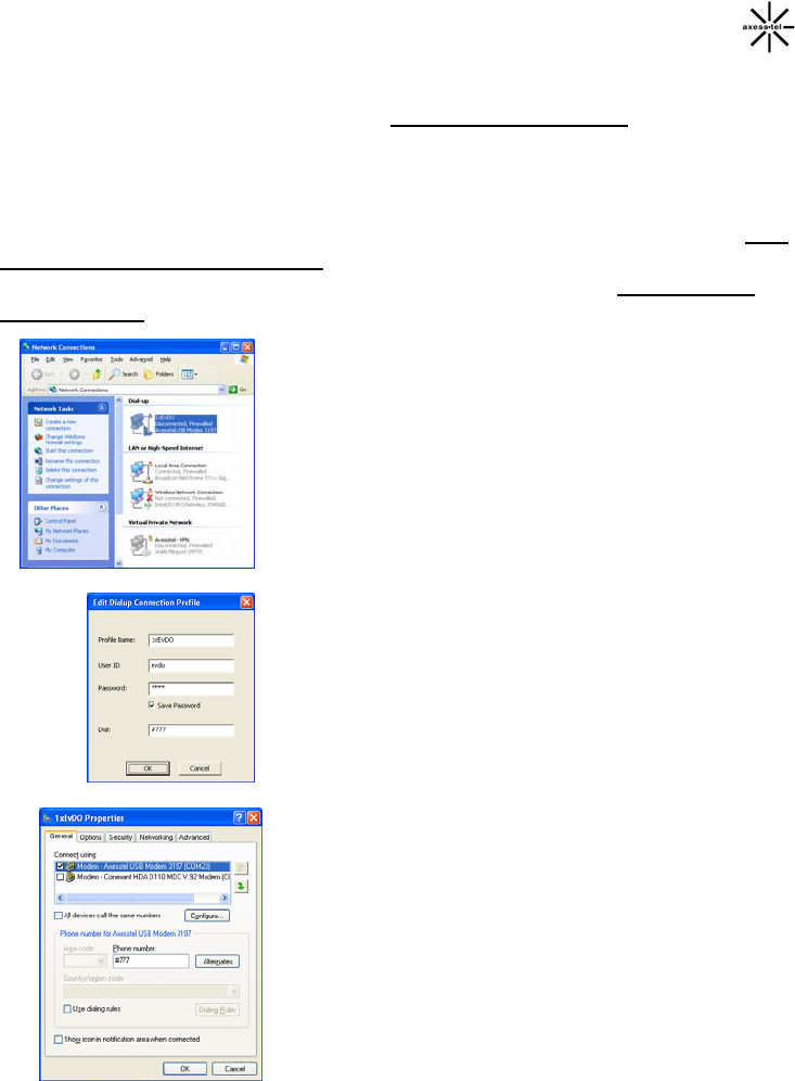
Connecting to Data Service with USB connection
After USB driver has been installed, you must use AxessManager to configure
and connect the Modem to the network. Please refer to AxessManager
Operational Guide chapter for detailed instructions. Make sure the Modem
selector switch is set to USB position before attempting the connection.
Normally Windows OS will automatically detect your Modem USB connection after
you have installed AxessManager. If for some reasons Windows OS failed to
complete this task, you may need to perform the following steps after installing
AxessManager to fully configure your Modem in USB mode.
1. Verify in Network Connection window that
USB connection has been created in “Dial
up” section. The connection name is set by
your service provider (default name is
WCDMA). You can also find the connectio
name in AxessManager utility, USB
Con
n
nection Profile tab
2. If no USB connection appears in Dial up
section, go to AxessManager utility, USB
Connection Profile tab, highlight the
connection name your service provider has
created, click Edit and OK to accept the
setup. This will add the connection to the
Network Connection window.
3. In very rare cases, Windows OS may
associate the wrong modem to your Dial up
connection. To verify, right click on the Dial
up connection name in step 1 above and
select Properties. You should see the
Axesstel USB Modem selected and the
correct dial number entered. If not, update
the fields with correct value.
21
Connection Using Ethernet (RJ45) Ports
Although the Modem comes with drivers and enabling software, you don’t have to
install and use them if you simply want to connect to the Internet through the
Ethernet (RJ-45) ports, assuming that your Modem has been activated with the
network
First go to AxessManager Operation Guide to authenticate and configure your
RUIM (if needed) before returning to the below instructions.
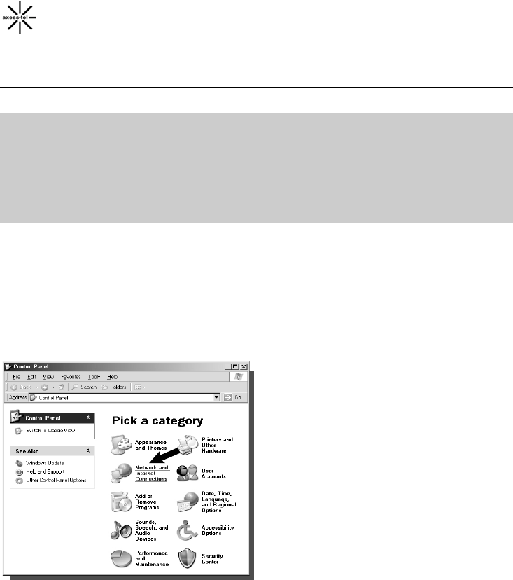
Configuring Your PC
The Modem’s Ethernet is configured with DHCP by default. This means that IP
address of your PC is automatically assigned by the HSPA Modem. If for some
reasons, the PC’s cannot get IP address and cannot make connection to Internet,
use the following steps to check the TCP/IP setting of your “Local Area
Connection”.
1. Click the Start button, select Settings,
and select Control Panel. Click on
“Network and Internet Connection” icon.
NOTE: DHCP stands for Dynamic Host Configuration Protocol. Your Modem has
a built-in DHCP server. The DHCP server will automatically assign an IP
address to the computers on the LAN. Be sure to set each client PC’s
TCP/IP settings to “obtain an IP address automatically”.
22
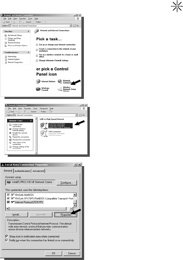
2 Double-click on “Network
Connection”.
3 Go to Local Area Connection
Properties.
4 Select the “Internet protocol
(TCP/IP)”. If there is no TCP/IP line
listed, you will need to install
TCP/IP first.
5 Press the “Properties” button.
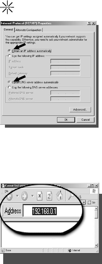
23
6 Check “Obtain an IP address
automatically”.
7 Check “Obtain DNS Server
address automatically”.
8 Click OK to exit Properties
9 If asked to re-start the PC, click
“YES”.
Configuring Ethernet Connection
Your HSPA Modem provides an embedded Web-based Management Utility to
help you configure it using your Web Browser. Follow these steps to configure
your Modem’s Ethernet connection.
1. Open your Web browser and enter
192.168.0.1 in the address bar
24
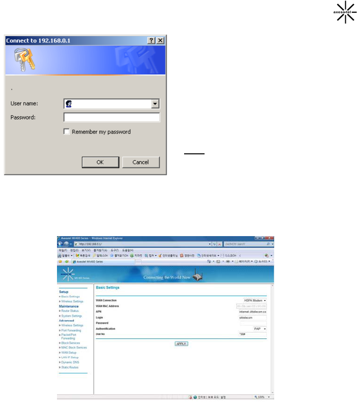
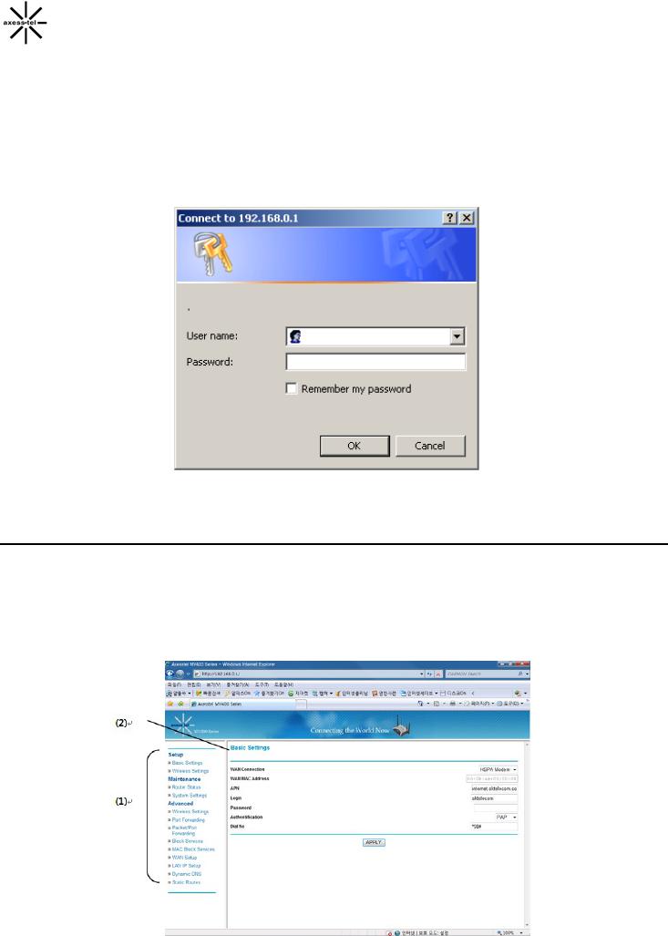
2. A pop-up window will appear. When
prompt for User name and password,
enter the following user id and
password.
User Name: admin
Password: admin
* If you have changed the user name
and the password, enter the new user
name and password.
Note: This user name and password
are only for the Web Manager access.
Changing these settings does not
change AxessManager user profile
name and password.
After entering the correct user name and password, the pop up window will
change to a web-based window.
Follow the steps in the chapter “Web Manager User Interface”, “Step 2 Navigate
web-based UI”, page 39 to complete the Modem’s Ethernet and Wi-Fi settings.
25
AxessManager Operational Guide
AxessManager is a SW utility that allows the administration of your Modem. One
computer at a time can log into the Modem via AxessManager for the purposes of
making changes to the settings of the Modem. Once a user has logged in to make
changes, all other computers connected to the Modem inherit the same settings.
For example, if the Modem is set to use only WCDMA data, all connections to the
network through the Modem RJ-45 ports or Wi-Fi will be WCDMA.
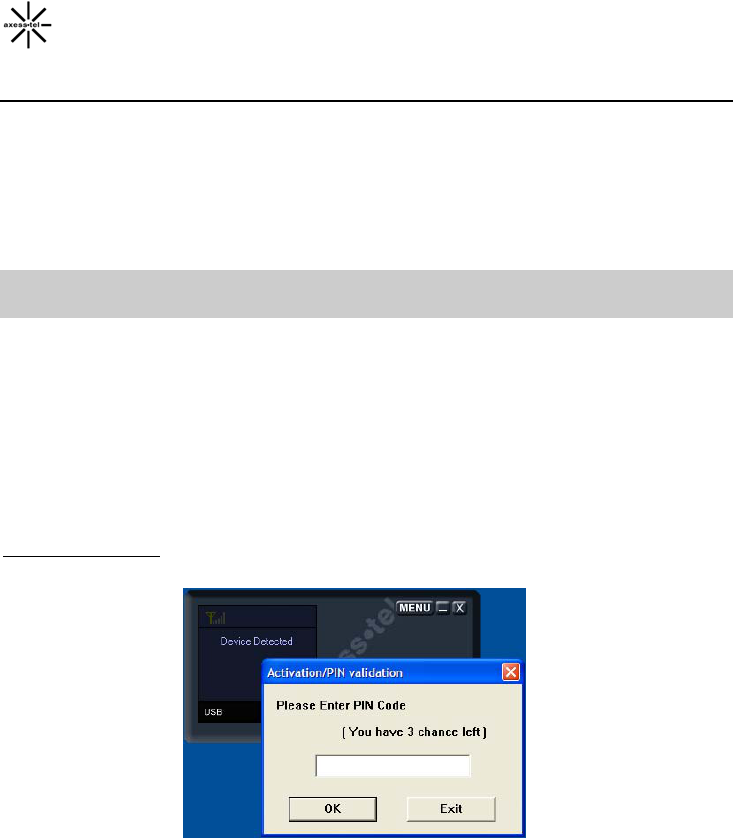
IMPORTANT: You must use AxessManager to authenticate your PIN (Personal
Identification Number) before connecting to the Modem.
MU430 PIN authentication
When you use MU430 for the first time, you need to go through AxessManager to
authenticate your PIN. Once your PIN is authenticated, and as long as you don’t
turn off the device, you don’t need to re-authenticate your PIN even if you get off
AxessManager (e.g. to connect via Wi-Fi or Ethernet ports). Also, you have an
option to de-activate PIN authentication in subsequent connection by selecting the
Unlock option in RUIM tab of Menu Window.
MU430 Validation
If you enter an invalid PIN for three consecutive times, your SIM card (and your
device) will lock up. To unlock the SIM, contact your service provider to obtain a
PUK (Personal Unblocking Key) code. With this code, you can set a new PIN for
your device.
26
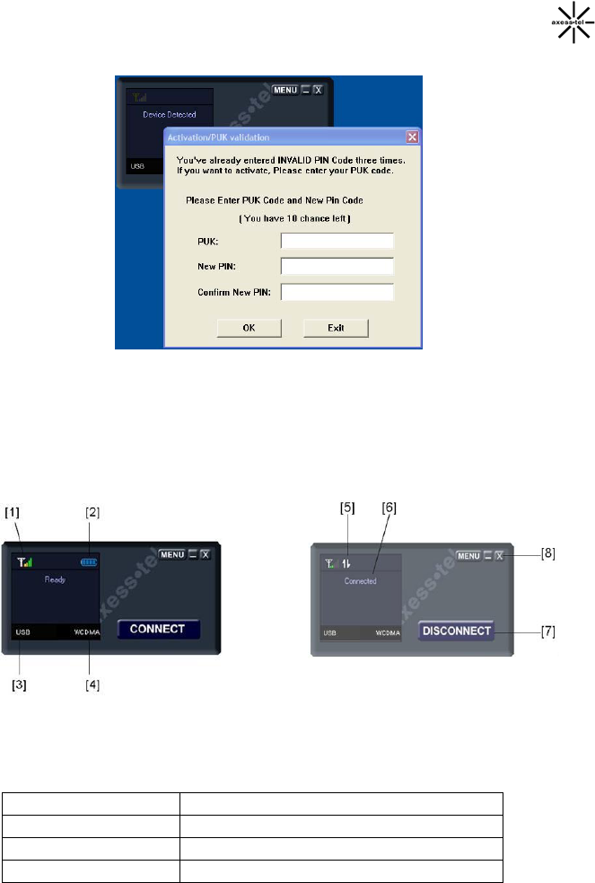
Using the Main Window User Interface
The Main window is the first page you will see when you access the
AxessManager User Interface (UI). The Main window shows you a quick view of
the Modem’s status and settings. All advanced setup pages can be reached from
this page.
1. Signal Strength Icon
This icon indicates the signal strength of network serving your Modem.
OFF No Modem connected to computer
Antenna only- Red Modem connected but no service
Antenna only-White Weak signal (< -111 dBm)
Antenna + 1 bar Low signal (-111 ≤ sig. < -103 dBm )

27
Antenna + 2 bars Medium-Low (-103 ≤ sig. < -98 dBm)
Antenna + 3 bars Medium signal (-98 ≤ sig. < -93 dBm)
Antenna + 4 bars Medium-high (93 ≤ sig. < -88 dBm)
Antenna + 5 bars Strongest signal (≥ -88 dBm)
2. Battery Icon
OFF No battery
Blinking red Battery error or very low
Blue empty battery Battery low level
Blue with 1 bar Battery level 25%
Blue with 2 bars Battery level 50%
Blue with 3 bars Battery level 75%
Blue with 4 bars Battery level close to 100%
Progressing 1- 4 bars Battery is charging
3. Network Connection Icon
This icon shows the wired network connection mode of your Modem. Only one
mode can be used at a time.
OFF No computers connected to Modem
Ethernet RJ-45 port or Wi-Fi is in use
USB USB port is in use
COM COM port is in use
Note that there is a USB/Ethernet switch in the front of the Modem to select
which preferred mode for your connected computers. The COM mode can only
be activated from the "Menu" window.
4. Air Interface Icon
This icon informs you that the Modem is tuned to a WCDMA or other network.
By default your Modem is programmed to search and use WCDMA network. If
unavailable, the Modem will try to search for a others.
OFF No network available, no service
WCDMA WCDMA network is available
GSM other network is available
5. Activity Icon
This icon indicates data activity between your Modem and the network.
28
OFF No data activity
Blinking arrows Data passing through your Modem
Steady arrows Modem is in connect or dormant state
6. Info Text Messages
There are various Info messages displayed in this window. These messages
inform you various statuses of your Modem.
No Device No devices connected to Modem
Searching… Your Modem is searching networks
for services
No Service Your Modem cannot detect any
network after search completed
Ready Your Modem is ready for network
connection
Device Detected
Connected Your Modem is connected to the
network
Connected
(Dormant)
Your Modem is connected to the
network but is inactive
Battery Low
Battery Error
7. Connect/Disconnect Button
This button allows you to connect or disconnect your Modem to the network. It
will toggle between two states Connect and Disconnect. The Disconnect button
appears only when your Modem is currently in the Connected or Connected
(Dormant) modes. This allows you to turn off the sessions by disconnecting your
Modem from the service network. In all other Modem modes, the Connect
button will appear. Note that although the Connect button appears, the Info Text
message must show “Ready” before you can connect to the network.
8. Menu/X/- Buttons
The Menu button gives you access to additional advanced Modem setting and
configuration such as Network Setup, Options and Status selection. The X
button exits AxessManager utility. Note that exiting the utility does not mean
turning off your Modem. For example, if you exit the utility while the Modem is in
Connected or Connected (Dormant) mode, other computers can be plugged in
29
one of the ports and use the service. The - button allows you to minimize
AxessManager utility into Window tray.
Using the Menu Window
The Menu window is the main Interface that gives you access to more advanced
settings of your Modem. The Menu window is a stand-alone, pop-up window that
appears after you click the Menu button in the AxessManager main window. Once
you enter the Menu window, navigating to different tabs may result in subsequent
window pop-up to allow different configurations and settings of your Modem. In
the sections below, you will see each tab's functionality and operation.
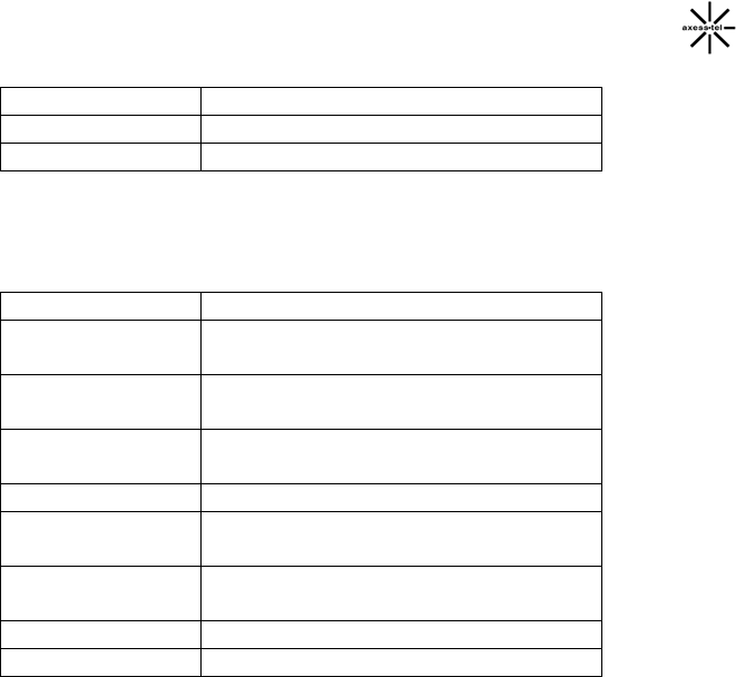
1. About Tab
This tab informs you the basic details of your Modem. There are no further
actions needed in this tab. There is a slight difference in appearance when your
Modem is configured with Ethernet setting. When it occurs, About tab also
informs you the SW version of the Linux SW used to handle the Ethernet
function.
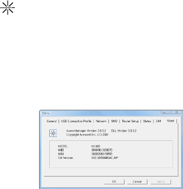
2. General Tab
This tab allows you to specify the system selection of your Modem. It also let
you choose the COM port setting.
30
A. SMS Validity Period/Select Inbox
• SMS Validity Period
- Select Validity period. It will keep the SMS message on the
SMS server for desired period.
• Select Inbox
- Select inbox. It will choose the first storage location for SMS
B. Disable Automatic USB Port Search
This check lets you disable the automatic COM port assignment to use
for your computer USB and COM connections with the Modem. If
selected, a drop down menu with a list of available COM ports will
appear and you will need to specify the port number from that list.
31
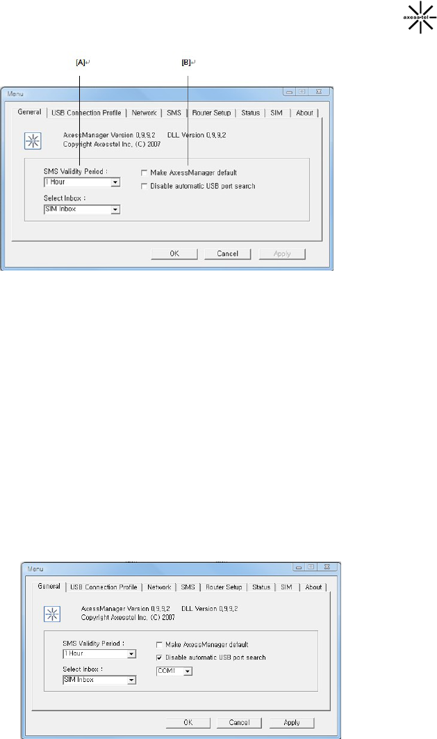
3. Status Tab
This tab shows you various performance statuses of your Modem. There are no
further actions needed in this tab.
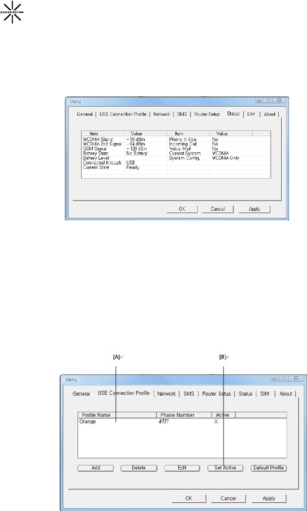
4. USB Connection Profile Tab
This tab lets you define and manage the USB connection of your Modem. You
only have to specify items in this tab if you choose to connect and operate your
computer with the Modem via the USB port. Note that there is only one USB
port on the Modem hence there is only one single user who can use the Modem
in this mode. In normal operation, there are two USB connection profiles
predefined: one for WCDMA connection and one for GSM connections. These
two profiles are included in the Install CD and downloaded to your PC during
the installation process.

32
A. Profile List
This window contains all the USB connection profiles previously defined
in the computer currently in use to connect with the Modem and
indicates which profile is active. Note that this list is stored in the
computer and not in the Modem, hence any changes you make in the
profiles are only stored locally. If you have more than one PC and intent
to use the USB connection with the Modem (not simultaneously) you
will need to make the same changes in each PC.
B. Add/Delete/Edit Profile
These buttons allows you to manage all USB connection profiles
previously defined in the computer.
To add a new profile, simply click the "Add" button. A secondary pop up
window will appear and ask you to enter all parameters associated with
the new connection. These parameters are:
• Profile Name
• User Id
• Password
• Dialed Number
• APN
Since these parameters are sent over the air to the network serving
your Modem, we advise you to contact your Service Provider before
attempting this step.
To delete an existing profile, first highlight it by clicking the profile name
in the list then hit the "Delete" button.
To modify some settings of an existing profile, highlight it in the profile
list then click the "Edit" button. A secondary pop up window similar to
the "Add" pop up window will appear. This window is populated with
existing parameter values. You simply change the appropriate
parameter as needed. Again, we advise you to contact your Service
Provider before attempting this step.
5. SIM Tab
This tab lets you modify the setting of your Modem RUIM validation. You can
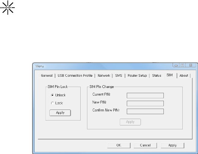
33
choose to permanently unlock your device so that future access will not require
PIN entering (hence no need to go through AxessManager). You may want to
do this if your device is shared with other users.
Also this tab allows you to modify your current PIN.

34
Web Manager User Interface
The Web Manager User Interface is a web-based tool that you can use to set up
the Modem if you don’t want to use the default setting of Install CD. You can also
use it to manage advanced functions of the Modem. From the User Interface, you
can perform the following tasks:
• View the Modem’s current settings and status
• Configure the Modem's router function to connect to your Service
Provider with the settings that they provided you
• Change the current network settings such as the Internal IP address, the
IP address pool, DHCP settings, and more
• Set the Modem’s firewall to work with specific applications (port
forwarding)
• Set up security features such as client restrictions, MAC address filtering,
WEP, and WPA
• Enable the DMZ feature for a single computer on your network
• Change the Modem’s internal password
• Reboot the Modem
• Back up your configuration settings
• Reset the Modem’s default settings
• Update the Modem’s firmware
Before you use the Advanced User Interface, you will need to have a User Name
and Password of the Modem. Please contact your Service Provider to obtain
them.
Step 1 │ Access Network Setup
1.1. Connect the PC to your Modem using the CAT-5 Ethernet cable. Use ANY
one of the Ethernet ports on your Modem.
1.2 If you have installed AxessManager, start AxessManager utility if it is not
already active. From Main window, select Menu button. Refer to
AxessManager Operational Guide for instructions if needed. If you have not
installed AxessManager, refer to section “Configuring Ethernet Access” to
35
advance to step 2. Skip the rest of step 1.
1.3 From Menu window, select "Network" tab. A secondary pop up window will
appear and ask you to enter User Name and Password.
1.4 Enter the User Name and Password then click "OK". The pop up window
will change to a web-based window
Step 2 │Navigate web-based UI
2.1 The Basic Setting page is the first page you will see when you access the
web based Advanced User Interface (UI). The basic setting page shows you
a quick view of the Modem’s login setting. All advanced setup pages can be
reached from this page.
36
1. Quick Navigation Links
You can go directly to any of the Modem’s UI pages by clicking directly
on these links. The links are divided into logical categories and grouped
by tabs to make finding a particular setting easier to find.
2. Page Name
The page you are on can be identified by this name. This User Manual
will sometimes refer to pages by name. For instance “Advanced > LAN
IP Setup” refers to the “LAN IP Setup” page.
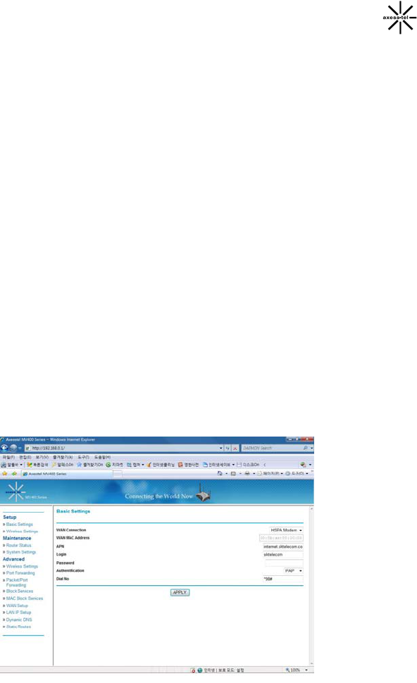
Basic Settings
Clicking on the header of the “Basic Settings” tab will take you to the “Basic
Settings” header page. From this page, the Modem’s basic settings can be
modified. These settings include:
¾ WAN Connection. A drop down menu allows users to change the
providers. The default value is HSPA
¾ MAC Address
¾ PPP Login ID and password (if applicable)
¾ Authentication Method. A drop down menu allows users to change the
authentication method. The default value is PAP
¾ Dial No
37
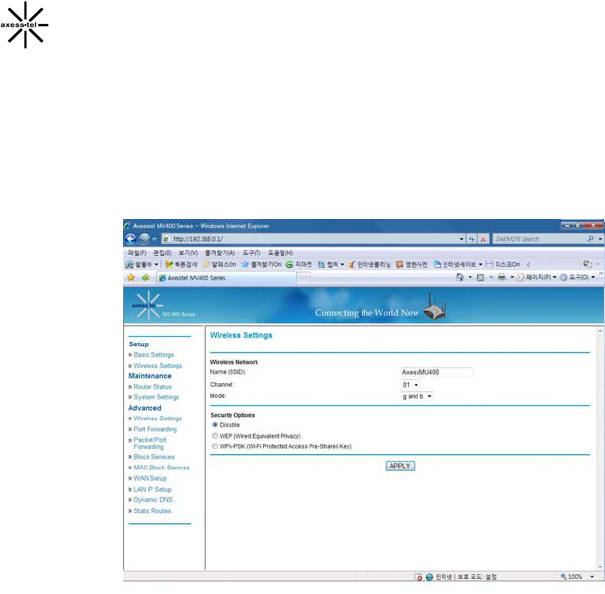
Configuring the Wireless Network Settings
Clicking on the header of the “Wireless Settings” tab will take you to the
“Wireless Settings” header page. From this page, the Modem’s Wi-Fi router
wireless radio can be enabled or disabled (the default setting is enabled). There
are options that allow you to make changes to the Wi-Fi wireless network
settings.
Changing the Wireless Network Name (SSID)
To identify your wireless network, a name called the SSID (Service Set
Identifier) is used. The default SSID of the Modem is “AxessMU430”. You can
change this to anything you want to or you can leave it unchanged. If there are
other wireless networks operating in your area, you will want to make sure that
your SSID is unique (does not match that of another wireless network in the
area). To change the SSID, type in the SSID that you want to use in the “SSID”
field and click “Apply Changes”. The change is immediate. If you make a
change to the SSID, your wireless-equipped computers may also need to be
reconfigured to connect to your new network name. Refer to the documentation
of your wireless network adapter for information on making this change.
Using the Wireless Mode Switch
Your Modem can operate in three different wireless modes: “g and b”, “g only”,
and “b only”.

38
g and b Mode
In this mode, the Modem is compatible with 802.11b and 802.11g wireless
clients simultaneously. This is the factory default mode and ensures
successful operation with all Wi-Fi compatible devices. If you have a mix of
802.11b and 802.11g clients in your network, we recommend setting the
Modem to g and b mode. This setting should only be changed if you have a
specific reason to do so.
g only Mode
g only mode works with 802.11g clients only. This mode is recommended only
if you want to prevent 802.11b clients from accessing your network. To switch
modes, select the desired mode from the “Wireless Mode” drop-down box.
Then, click “Apply Changes”.
b only Mode
We recommend you DO NOT use this mode unless you have a very specific
reason to do so. This mode exists only to solve unique problems that may
occur with some 802.11b client adapters and is NOT necessary for
interoperability of 802.11g and 802.11b standards.
When to use b only Mode
In some cases, older 802.11b clients may not be compatible with 802.11g
wireless. These adapters tend to be of inferior design and may use older
drivers or technology. Switching to this mode can solve problems that
sometimes occur with these clients. If you suspect that you are using a client
adapter that falls into this category of adapters, first check with the adapter
vendor to see if there is a driver update. If there is no driver update available,
switching to b only mode may fix your problem. Please note that switching to
b only mode will decrease 802.11g performance.
Changing the Wireless Channel
There are a number of operating channels you can choose from. (The
available channel is 1~11). Your Modem is configured to operate on the
proper channels for the country you reside in. The default channel is 11
(unless you are in a country that does not allow channel 11). The channel can
be changed if needed. If there are other wireless networks operating in your
area, your network should be set to operate on a channel that is different than
the other wireless networks. For best performance, use a channel that is at
least five channels away from the other wireless network. For instance, if
another network is operating on channel 11, then set your network to channel

39
6 or below. To change the channel, select the channel from the drop-down list.
Click “Apply Changes”. The change is immediate.
Securing your Wi-Fi® Network
Here are a few different ways you can maximize the security of your wireless
network and protect your data from prying eyes and ears. This section is
intended for the home, home office, and small office user. At the time of this
User Manual’s publication, there are two encryption methods available.
WEP (Wired Equivalent Privacy)
WEP (Wired Equivalent Privacy) is a common protocol that adds security to
all Wi-Fi compliant wireless products. WEP was designed to give wireless
networks the equivalent level of privacy protection as a comparable wired
network.
WPA (Wi-Fi Protected Access)
WPA (Wi-Fi Protected Access) is a new Wi-Fi standard that was designed to
improve upon the security features of WEP. To use WPA security, the drivers
and software of your wireless equipment must be upgraded to support WPA.
These updates will be found on the wireless vendor’s website. There are two
types of WPA security, WPA-PSK (no server) and WPA (with radius server).
WPA-PSK (no server) uses what is known as a pre-shared key as the network
key. A network key is basically a password that is between eight and 63
characters long. It can be a combination of letters, numbers, or characters.
Each client uses the same network key to access the network. Typically, this
is the mode that will be used in a home environment.
Maintenance: Router Status
Clicking on the header of the “Router Status” tab will take you to the “Router
Status” header page. A quick description of the functions can be found here.
1. IP Address
The “IP address” is the internal IP address of the Modem. The default IP
address is “192.168.0.1”. To access the web based Advanced User Interface,
type this IP address into the address bar of your browser. This address can be
changed if needed.
2. Subnet Mask
This is a unique, advanced feature of your Axesstel Modem. It is possible to
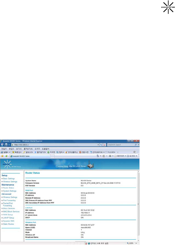
40
change the subnet mask if necessary; however, do NOT make changes to the
subnet mask unless you have a specific reason to do so. The default setting
is “255.255.255.0”.
From this page, users can see all settings associated with the Modem’s router
network functions. These functions include:
¾ Account Name and Firmware Version
¾ WAN Port: MAC Address, IP Address, DHCP choice, IP Subnet Mask
and Domain Name Server Address
¾ LAN Port: MAC Address, IP Address, DHCP choice and IP Subnet
Mask
¾ Wi-Fi Port *: SSID, Region, Channel, Mode, Wireless AP status
(ON/OFF) and Broadcast Name status (ON/OFF)
Users can click the button “Show Statistic” to see a graphic display of the router
performance.
Configuring Port Forwarding
Clicking on the header of the “Port Forwarding” tab will take you to the “Port
Forwarding” header page. This function will allow you to route external (Internet)
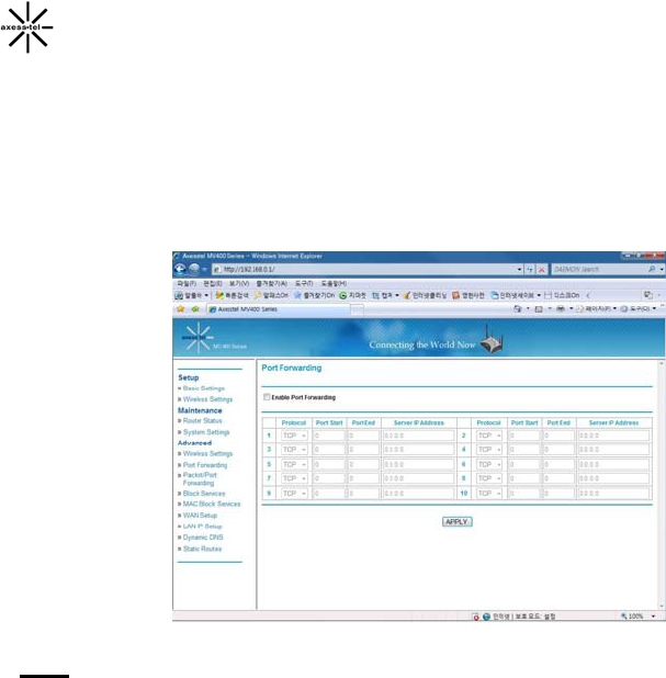
41
calls for services such as a web server (port 80), FTP server (Port 21), or other
applications through your Router to your internal network. Since your internal
computers are protected by a firewall, computers outside your network (over the
Internet) cannot get to them because they cannot be “seen.” A list of common
applications has been provided in case you need to configure the “Port
Forwarding” function for a specific application. You will need to contact the
application vendor to find out which port settings you need.
Note: This advanced feature should be employed by advanced users only.
Disable Port Forwarding
To disable Port Forwarding, uncheck the box “Enable Port Forwarding”.
Entering Settings into the Port Forwarding
To enter settings, select the service from the dropdown box “Protocol”. You will
see a list of common applications (FTP, HTTP, Net-Meeting…). Select the
desired applications, enter the IP address and the port number in the space
provided for the internal (server) machine and click “Apply”. Opening ports in
your firewall can pose a security risk. You can enable and disable settings very
quickly. It is recommended that you disable the settings when you are not using
a specific application.
Block Services
The Modem can be configured to restrict access to the Internet, email, or other
42
network services at specific days and times. Restriction can be set for a single
computer, a range of computers, or multiple computers.
To restrict Internet access to a single computer, for example, enter the IP address
of the computer you wish to restrict access to in the IP fields. Next, enter “80” in
both the port fields. Select “Block”.
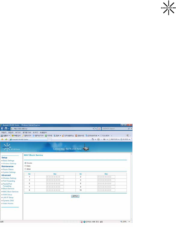
MAC Block Services
The MAC address filter is a powerful security feature that allows you to specify
which computers are allowed on the network. Any computer attempting to
access the network that is not specified in the filter list will be denied access.
When you enable this feature, you must enter the MAC address of each client
(computer) on your network to allow network access to each.
MAC Services Blocking can be set in three modes.
¾ Disable. In this mode, there is no restriction to any device connected to
the Modem whether it is through Wi-Fi or Ethernet ports.
¾ Deny. In this mode, the service table shows the client MAC address
being blocked by the Modem.
¾ Allow. In this mode, the service table shows the client MAC address
allowed by the Modem.
To modify the service table (i.e. to add, change address or remove clients)
43
simply enter the correct value and click “Apply”.
Note: You will not be able to delete the MAC address of the computer you are
using to access the Router’s administrative functions (the computer you are
using now).
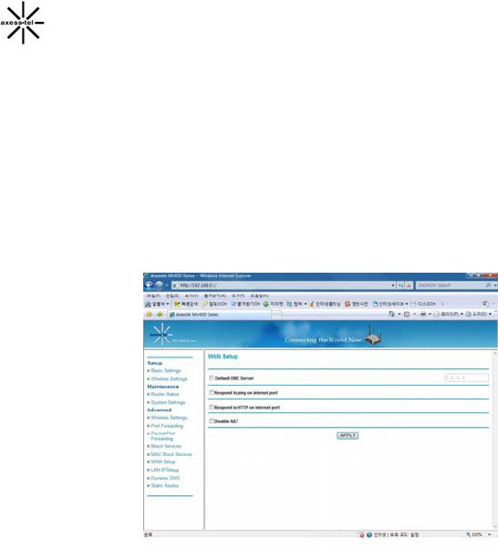
WAN Setup
Clicking on the header of the “WAN Setup” tab will take you to the “WAN Setup”
header page. From this page, the Modem’s DMZ, Internet Ping and HTTP can
be enabled or disabled.
Enabling the Demilitarized Zone (DMZ)
The DMZ feature allows you to specify one computer on your network to be
placed outside of the firewall. This may be necessary if the firewall is causing
problems with an application such as a game or video conferencing
application. Use this feature on a temporary basis. The computer in the DMZ
is NOT protected from hacker attacks.
WAN Ping Blocking
Computer hackers use what is known as “pinging” to find potential victims on
the Internet. By pinging a specific IP address and receiving a response from
the IP address, a hacker can determine that something of interest might be
there. The Modem can be set up so it will not respond to an ICMP ping from
the outside. This heightens the level of security of your Modem.
To turn OFF the ping response, select “Not Respond to Ping on Internet Port”
and click “Apply”. The Modem will not respond to an ICMP ping.
44
HTTP Ping Blocking
To turn OFF the HTTP response, select “Not Respond to HTTP on Internet
Port” and click “Apply”. The Modem will not respond to an HTTP ping.
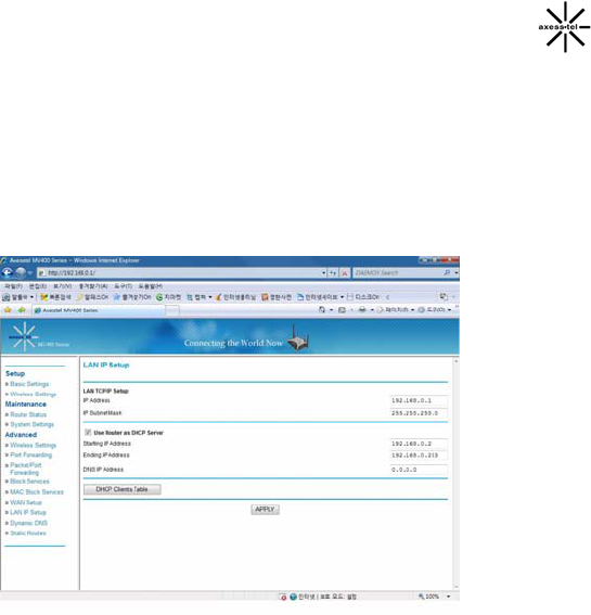
LAN IP Setup
Clicking on the header of the “LAN IP Setup” tab will take you to its header page.
LAN TCP/IP Setup
All settings for the internal LAN setup of the Router can be viewed and
changed here.
1. IP Address: The “IP address” is the internal IP address of the Modem. The
default IP address is “192.168.0.1”. To access the Web Manager User
Interface, type this IP address into the address bar of your browser. This
address can be changed if needed. To change the IP address, type in the
new IP address and click “Apply”. The IP address you choose should be a
non-routable IP.
Examples of a non-routable IP are:
192.168.x.x (where x is anything between 0 and 255), and
10.x.x.x (where x is anything between 0 and 255).
2. Subnet Mask: There is no need to change the subnet mask. This is a
unique, advanced feature of your Modem. It is possible to change the
subnet mask if necessary; however, do NOT make changes to the subnet

45
mask unless you have a specific reason to do so. The default setting is
“255.255.255.0”.
Use Router as DHCP Server
The DHCP server function makes setting up a network very easy by
assigning IP addresses to each computer on the network automatically. The
DHCP server can be turned OFF if necessary; however, in order to do so
you must manually set a static IP address for each computer on your
network. To turn off the DHCP server, de-select “Use Router As DHCP
Server” and click “Apply”.
Static Route
A static IP address connection type is less common than other connection types.
If your ISP uses static IP addressing, you will need your IP address, subnet
mask, and ISP gateway address. This information is available from your ISP or
on the paperwork that your ISP left with you. Type in your information, and click
“Apply”.
1. IP Address: Provided by your ISP. Enter your IP address here.
2. Subnet Mask: Provided by your ISP. Enter your subnet mask here.
3. ISP Gateway Address: Provided by your ISP. Enter the ISP gateway
address here.

46
Troubleshooting
Problem:
Installation CD does not automatically start.
Solution:
If the CD-ROM does not start the Install software automatically, it could be
that the computer is running other applications that are interfering with the
CD drive.
1. If the Install screen does not appear within 15—20 seconds, open up
your CD-ROM drive by double-clicking on the “My Computer” icon that
is located on your desktop.
2. Next, double-click on the CD-ROM drive that the Install Software CD
has been placed in to start the installation.
3. The Install should start within a few seconds. If, instead, a window
appears showing the files on the CD, double-click on the icon labeled
“EasyInstall.exe”.
Problem:
• The Install software completed installation, but my web browser
doesn’t work.
• I am unable to connect to the Internet. The Modem’s “Signal” light is
on and the “Connect” light is off.
Solution:
If you cannot connect to the Internet, the “Signal” light is on, and the
“Connect” light is off, the problem may be your connection type may not
match the ISP’s connection.
• If you have a “static IP address” connection, your ISP must assign
you the IP address, subnet mask, and gateway address. Please
refer to the section entitled “Alternate Setup Method” for details on
changing this setting.

47
• If you are still unable to access the Internet after verifying these
settings, please contact your Service Provider Technical Support.
Problem:
• The Install software completed installation, but my web browser
doesn’t work.
• I am unable to connect to the Internet. The Modem’s “Signal” light is
on and the “Connect” light is on.
Solution:
If the “Signal” light is on, and the “Connect” light is on, but you are unable to
access the Internet, there may be third-party firewall software installed on
the computer attempting to access the Internet. Examples of third-party
firewall software are ZoneAlarm, BlackICE PC Protection, McAfee Personal
Firewall, and Norton Personal Firewall.
If you do have firewall software installed on your computer, please make
sure that you properly configure it. You can determine if the firewall software
is preventing Internet access by temporarily turning it off. If, while the
firewall is disabled and Internet access works properly, you will need to
change the firewall settings to function properly when it is turned on.
Please refer to the instructions provided by the publisher of your firewall
software for instructions on configuring the firewall to allow Internet access.
If you are still unable to access the Internet after disabling any firewall
software, please contact your Service Provider Technical Support.
Problem:
I can’t connect to the Internet wirelessly from my computer but it works if I
use the Ethernet cable.
Solution:
If you are unable to connect to the Internet from a wireless computer,
please do the following:
1. Look at the lights on your Modem. Your Modem’s lights should be as
follows:
• The “Power” light should be on.

48
• The “Connected” light should be on and not blinking.
• The “WAN” light should be either on or blinking.
2. Open your wireless utility software by clicking on the icon in the
system tray at the bottom, right-hand corner of the screen.
3. The exact window that opens will vary depending on the model of
wireless card you have; however, any of the utilities should have a list
of “Available Networks”—those wireless networks it can connect to.
Problem:
My wireless network performance is inconsistent.
Data transfer is sometimes slow.
Signal strength is poor.
I am having difficulty establishing and/or maintaining a Virtual Private
Network (VPN) connection.
Solution:
Wireless technology is radio-based, which means connectivity and the
throughput performance between devices decreases when the distance
between devices increases. Other factors that will cause signal degradation
(metal is generally the worst culprit) are obstructions such as walls and
metal appliances. As a result, the typical indoor range of your wireless
devices will be between 100 to 200 feet. Note also that connection speed
may decrease as you move farther away from the Modem or access point.
In order to determine if wireless issues are related to range, we suggest
temporarily moving the computer, if possible, five to 10 feet away from the
Modem.
Changing the Wireless Channel - Depending on local wireless traffic and
interference, switching the wireless channel of your network can improve
performance and reliability. The default channel the Modem is shipped with
is channel 11. You may choose from several other channels depending on
your region (see the section titled “Changing the Wireless Channel” on page
41 for instructions on how to choose other channels).
Limiting the Wireless Transmit Rate - Limiting the wireless transmit rate can
help improve the maximum wireless range and connection stability. Most
wireless cards have the ability to limit the transmission rate. To change this
property, go to the Windows Control Panel, open “Network Connections”

49
and double-click on your wireless card’s connection. In the “Properties”
dialog, select the “Configure” button on the “General” tab (Windows 98
users will have to select the wireless card in the list box and then click
“Properties”), then choose the “Advanced” tab and select the rate property.
Wireless client cards are usually set to automatically adjust the wireless
transmit rate for you, but doing so can cause periodic disconnects when the
wireless signal is too weak; as a rule, slower transmission rates are more
stable.
Experiment with different connection rates until you find the best one for
your environment; note that all available transmission rates should be
acceptable for browsing the Internet. For more assistance, see your
wireless card’s user manual.
Note) Please press reset button on the main set. After pressing the reset
button, the main set will powered off (it will not powered on automatically,
please switch off/on the power switch to get started)

50
Technical Specifications
This chapter provides technical product data for the Modem.
Radio frequency and electrical specifications
Frequency Range
UMTS Band I (WCDMA2100) Rx: 2110~2170 MHz
Tx: 1920~1980 MHz
UMTS Band II (WCDMA1900) Rx: 1930~1990 MHz
Tx: 1850~1910 MHz
UMTS Band V (WCDMA850) Rx: 869~894 MHz
Tx: 824~849 MHz
GSM850 Rx: 869~894 MHz
Tx: 824~849 MHz
EGSM900 Rx: 925~960 MHz
Tx: 880~915 MHz
DCS1800 Rx: 1805~1880 MHz
Tx: 1710~1785 MHz
PCS1900 Rx: 1930~1990 MHz
Tx: 1850~1910 MHz
Channel Bandwidth 1.23 Mhz
Stability of frequency (Frx – 10 Mhz)
±
300 Hz
External appearance (mm) 160 x 178 x 40 mm
Weight 600 g (with battery)
Sending output maximum 0.23W E.R.P
Temperature of operation
Relative humidity
Operating Temperature: -10°C to +55°C
Storage Temperature: -20°C to +70°C

51
Adapter
Input: AC 110~240V 50~60Hz
Output: DC 12V/2A
Battery Operation 2.5 Hrs
AXT v7.0
FCC Compliance Information
This device complies with Part 15 of FCC Rules.
Operation is subject to the following two conditions:
(1) This device may not cause harmful interference, and
(2) This device must accept any interference received.
Including interference that may cause undesired operation.
Information to User
This equipment has been tested and found to comply with the limits for a Class B digital
device, pursuant to part 15 of the FCC Rules. These limits are designed to provide
reasonable protection against harmful interference in a residential installation. This
equipment generates, uses and can radiate radio frequency energy and, if not installed
and used in accordance with the instructions,
may cause harmful interference to radio communications. However, there is no guarantee
that interference will not occur in a particular installation. If this equipment does cause
harmful interference to radio or television reception, which can be determined by turning
the equipment off and on, the user is encouraged to try to correct the interference by one
or more of the following measures:
- Reorient or relocate the receiving antenna.
- Increase the separation between the equipment and receiver.
- Connect the equipment into an outlet on a circuit different from that to which the receiver
is connected.
- Consult the dealer or an experienced radio/ tv technician for help.
CAUTION
The user who makes changes or modifications to the unit without the express
approval by the manufacturer will void user authority to operate the equipment.

Notice
OEM integrators and installers are instructed that the phrase. This device contains
transmitter FCC ID: PH7MU430 must be placed on the outside of the host.
Warning: Exposure to Radio Frequency Radiation The radiated output
power of this device is far below the FCC radio frequency exposure
limits. Nevertheless, the device should be used in such a manner that
the potential for human contact during normal operation is minimized.
In order to avoid the possibility of exceeding the FCC radio
frequency exposure limits, human proximity to the antenna should
not be less than 20cm during normal operation. The gain of the
antenna for Cellular band must not exceed-1.270 dBi.
The gain of the antenna for PCS band must not exceed -1.81000dBi.

52