Axesstel MV140N CDMA/PCS CDMA 1xEV-DO USB Modem User Manual Manual
Axesstel Inc CDMA/PCS CDMA 1xEV-DO USB Modem Manual
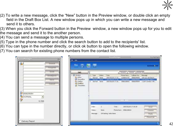
UserManual.wiki
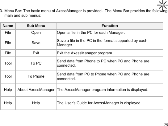
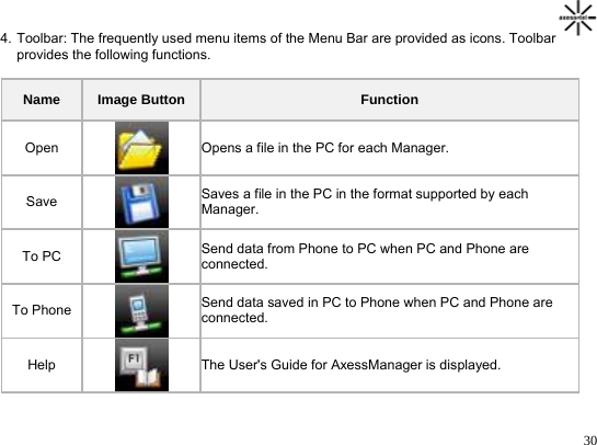
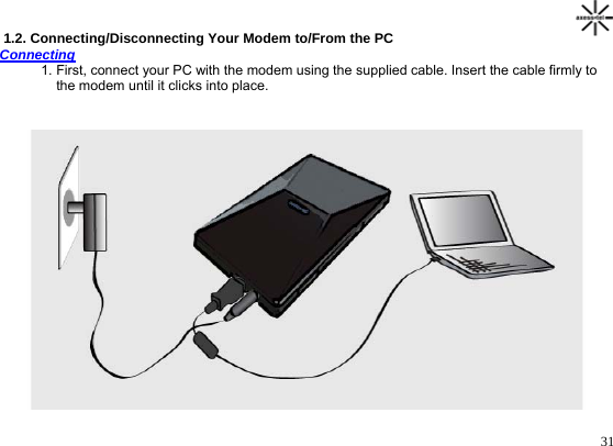
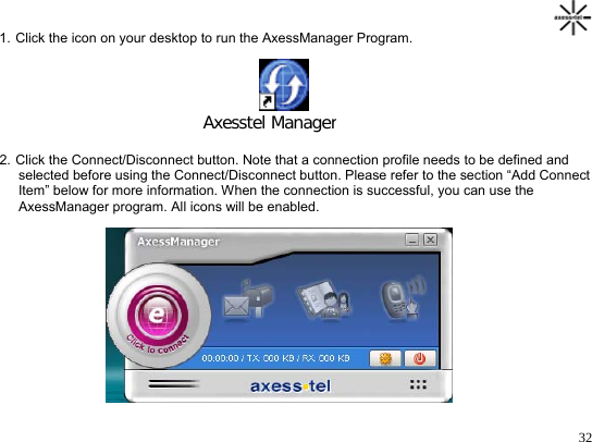
>
Axesstel
>
MV140N User Manual
Manual
Navigation menu
Upload a User Manual
Namespaces
Wiki Guide
HTML
PDF
Info
Views
User Manual
Discussion / Help
Navigation