Axesstel MV640 CDMA 1x ED-DO rev.B Router User Manual
Axesstel Inc CDMA 1x ED-DO rev.B Router
UserManual.wiki
>
Axesstel
>
MV640 User Manual
User Manual
Navigation menu
Upload a User Manual
Namespaces
Wiki Guide
HTML
PDF
Info
Views
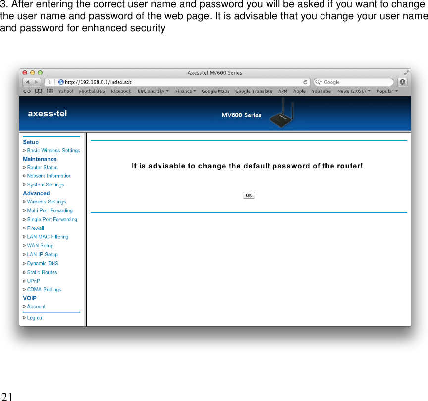
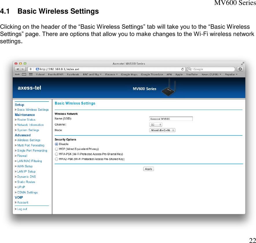
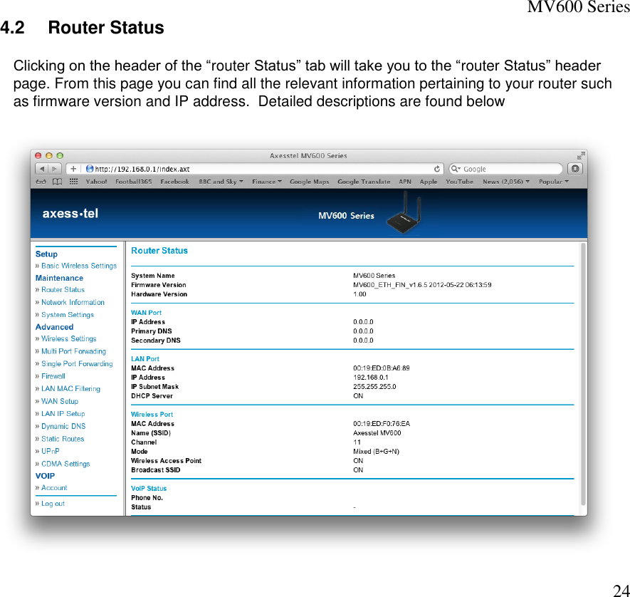
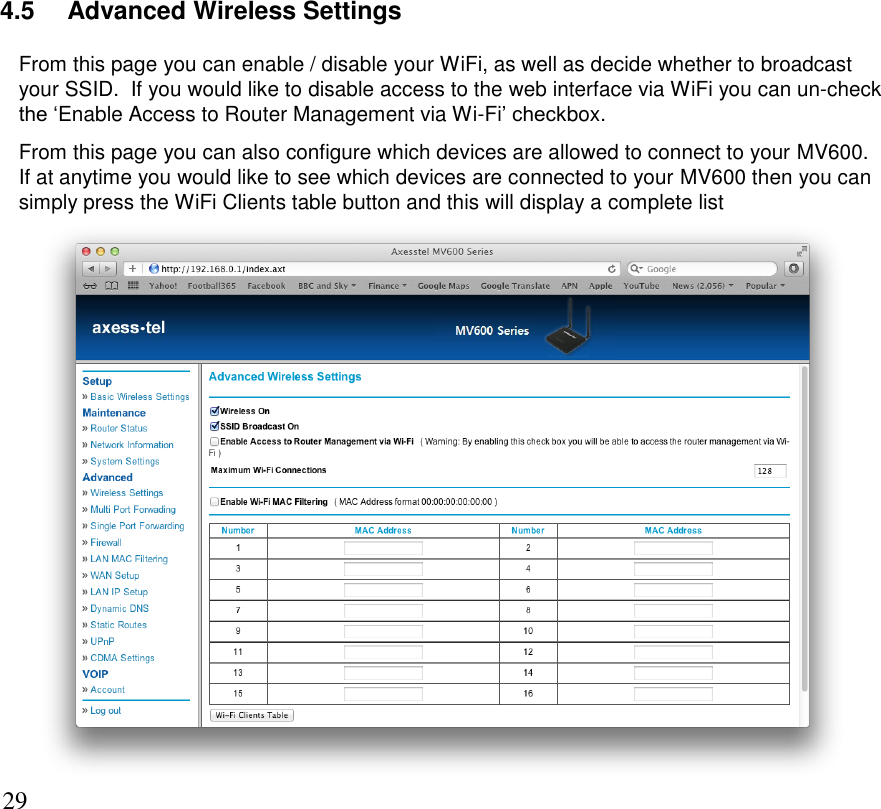
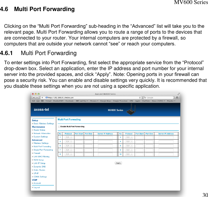
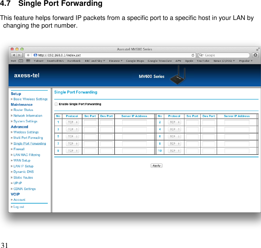
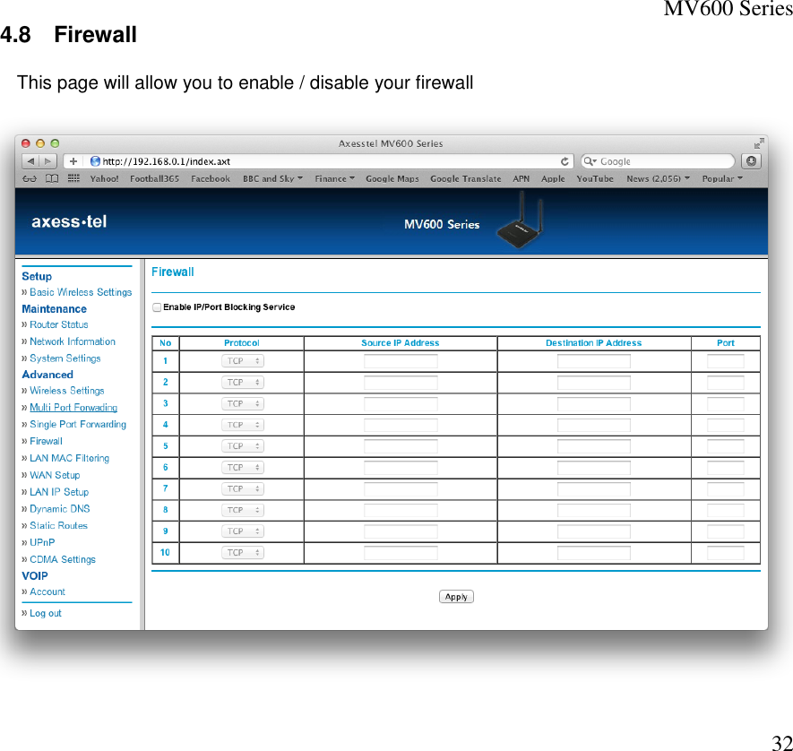
User Manual
Discussion / Help
Navigation