Axesstel SJE10 WLAN Access Point Smart Jacket User Manual SJE10 manual OK
Axesstel Inc WLAN Access Point Smart Jacket SJE10 manual OK
UserManual.wiki
>
Axesstel
>
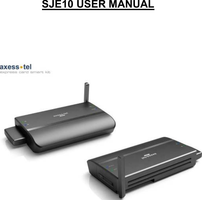
SJE10 User Manual
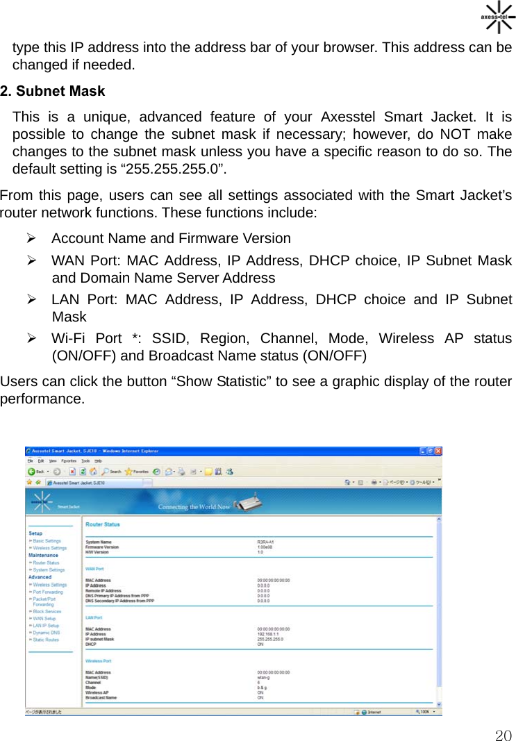
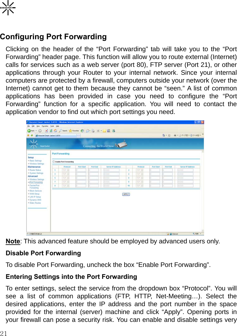
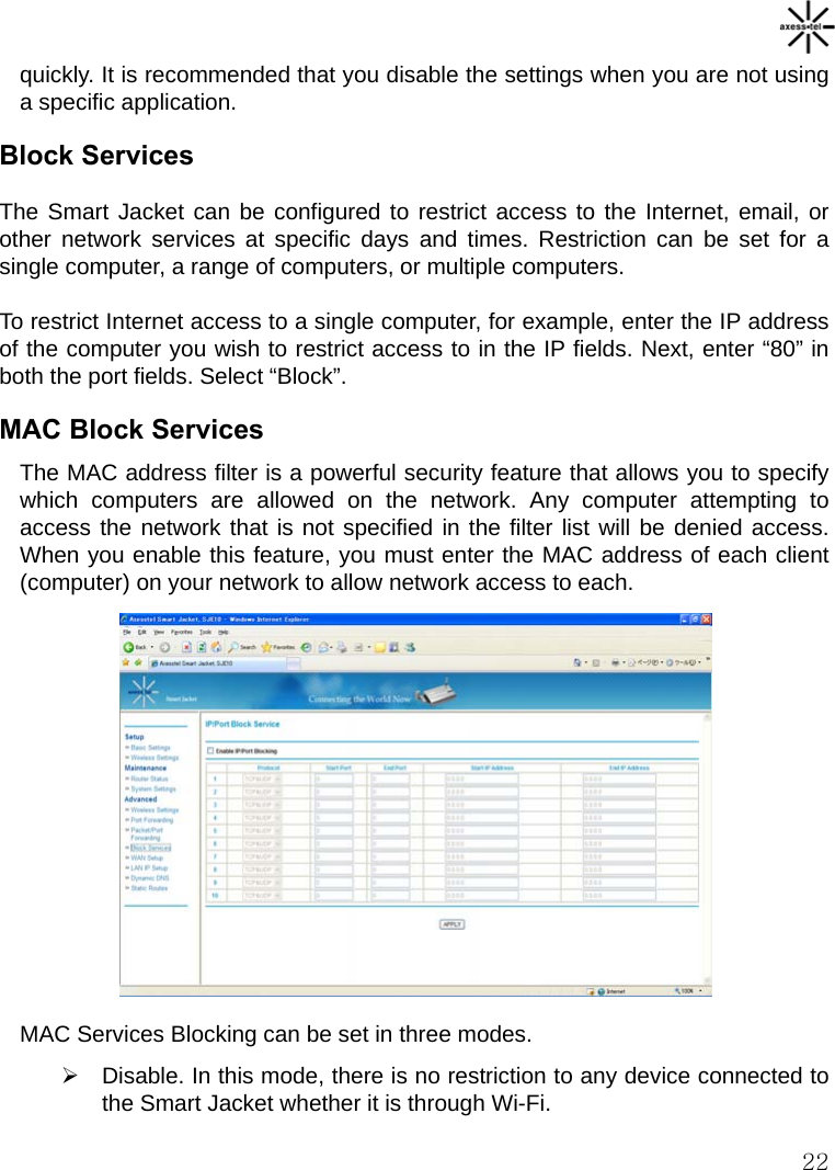
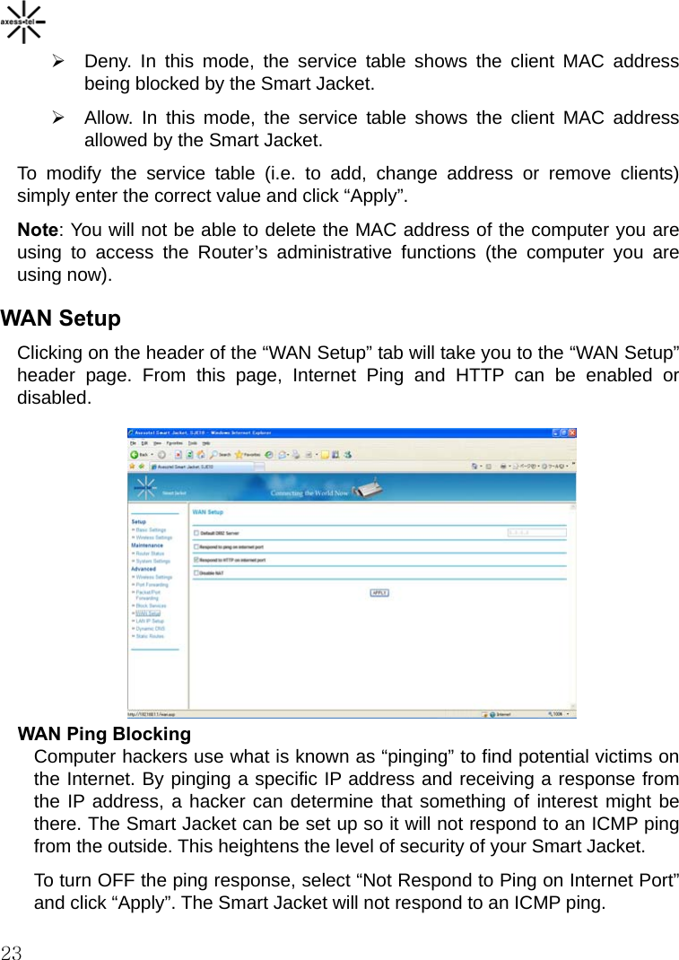
User Manual
Navigation menu
Upload a User Manual
Namespaces
Wiki Guide
HTML
PDF
Info
Views
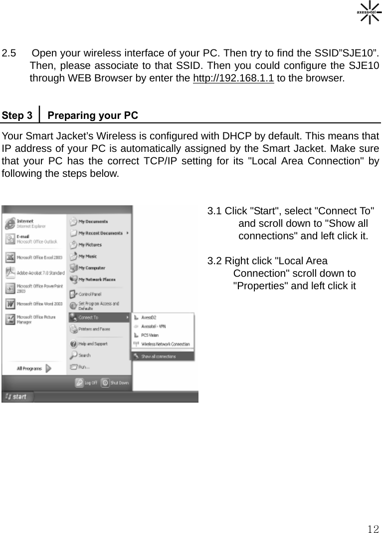
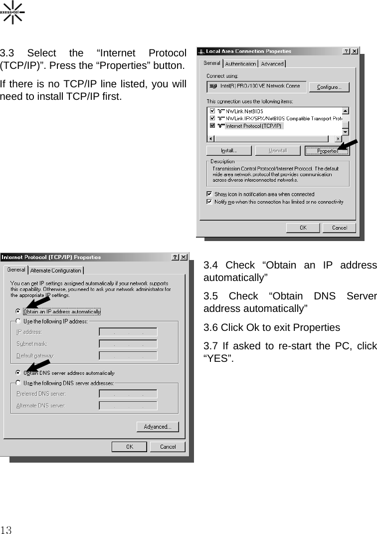
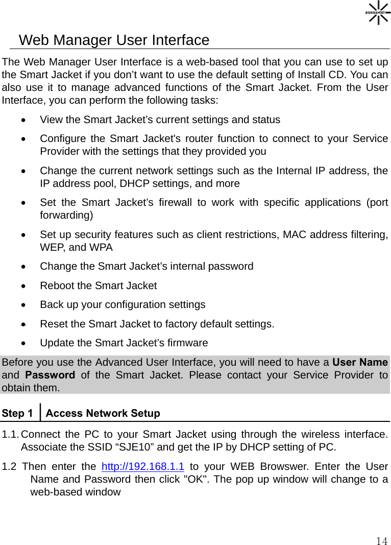
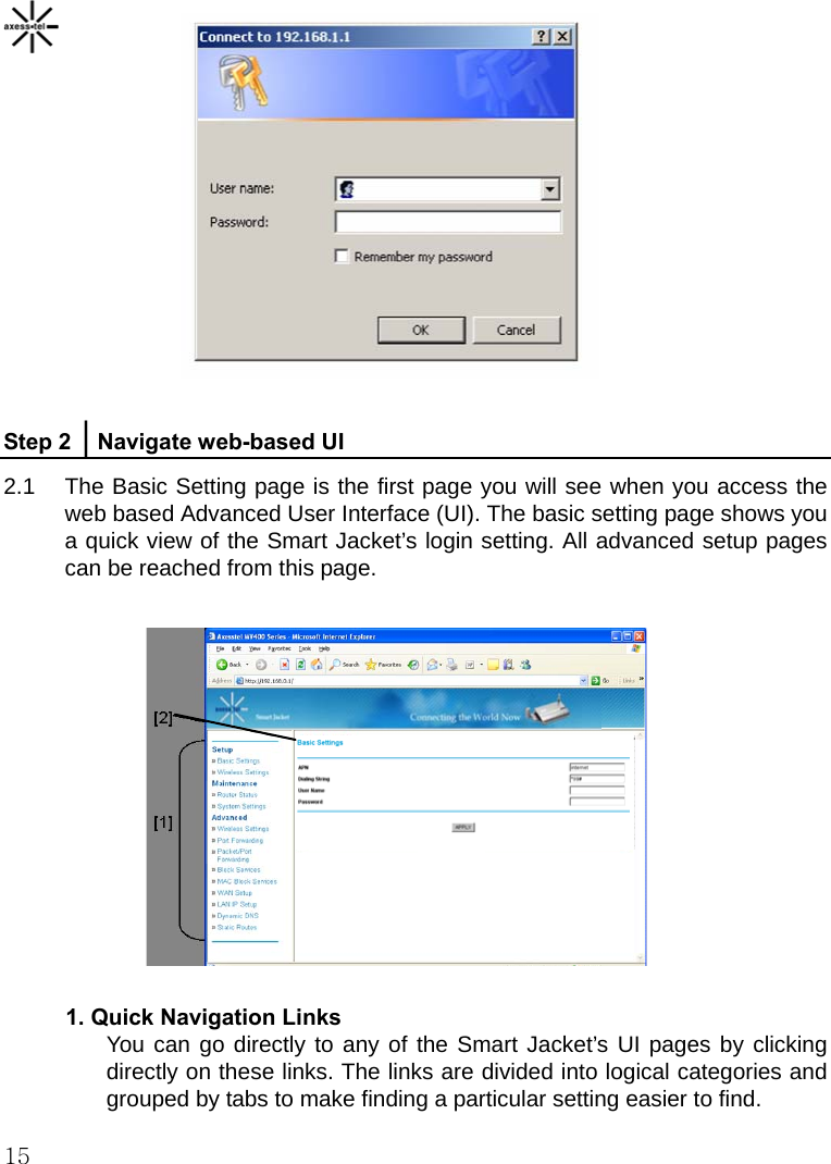
User Manual
Discussion / Help
Navigation