Axesstel TX240G CDMA2000 Terminal User Manual User ID and Password
Axesstel Inc CDMA2000 Terminal User ID and Password
Axesstel >
User manual
TX240G User Manual STD Ver. 0.2
1

TX240G User Manual Ver. 0.2
2
INTRODUCTION
OVERVIEW
TX240G is a Fixed Wireless Terminal designed to provide better wireless connectivity between wired
landline telephone (POTS) and CDMA 800/1900 dual bands network with high sensitivity to receive
signal and large transmitting power to expand extensively the effective coverage of CDMA service.
Global Positioning System (A-GPS) feature provides E911 service with accurately determining the
location of caller.
FEATURES
- CDMA2000 1x (backward compatible to IS-95 A/B) 800/1900 MHz Dual Bands
- A-GPS for E911 (SMA Antenna Connector)
- TTY/TDD Telephone Support
- 3 multi-colored LED Indicators (Signal, Mode, Voice Mail Waiting and Power)
- 2 R-J11 Ports (with max. 5 REN)
- Dial-Tone and DTMF Generation
- Desktop and Wall-Mountable
- Call Waiting, Three-way Calling and Call Forwarding
- Call Restriction
- Type II Caller ID (or Call Waiting ID)
- OTA(IS-683A)

TX240G User Manual STD Ver. 0.2
3
SAFETY PRECAUTIONS
1. Avoid placing the terminal in a dusty location, or near a source of gas or fire.
2. Don not shake, hit or drop the terminal.
3. To clean the outside of the terminal, use only a soft, dry cloth. The chemicals in alcohol, benzene or
Acetone can damage the surface of the terminal.
4. Do not twist or pull the cables.
5. Do not disassemble the terminal.
6. Do not use the power adapter if:
- The power cord is damaged.
- The adapter has been damaged in any way.
7. Use only the AXESSTEL provided adapter. Do not use the AXESSTEL adapter for any other
Purposes.
8. Use only the AXESSTEL provided antenna. Do not use the antenna for any other purposes..
9. Frequency and length of use can affect the life of the self-charging battery. Contact your customer
service if the battery is not operating properly.
10. Use only the designated self-charging battery. Dispose of exhausted batteries properly.
Never discard a battery in or near fire or flame.
11. Do not use the terminal near water, for example, near a bathtub, sink, wet basement, or swimming
pool.
NOTE: The input voltage and the shape of the plug may vary from country to country.
TX240G User Manual Ver. 0.2
4
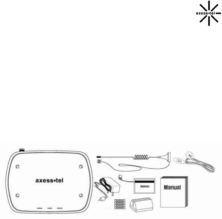
PACKAGE CONTENTS
After opening the package, check to make sure that you have all the parts shown below.
If any item is missing or broken, please call customer service.
- Axesstel 1x Fixed Wireless Terminal
- CDMA Dipole Antenna
- GPS Antenna with Cable
- Power Adapter (Input: AC100-240V, 50/60Hz / Output:5V/2A)
- Backup Battery
- User Manual or Quick Guide
- RJ-11 Phone Cord
- PSTN Tester
- RJ11 Cross Adaptor
CAUTION: Use the provided power adapter only. Using other power adapter may damage
the Terminal permanently.
TX240G User Manual STD Ver. 0.2
5
BASIC INSTALLATION
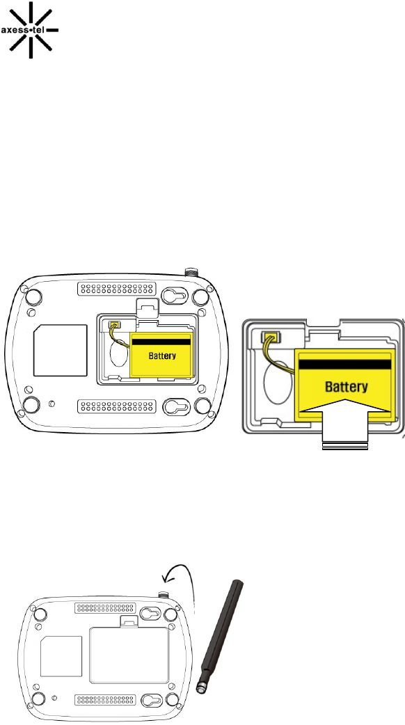
INTERNAL BATTERY INSTALLATION
This TX210G operates by receiving electricity from an electrical outlet or internal battery.
1. Open battery cover on the bottom side of the terminal.
2. Connect the Battery power cable to terminal.
3. Insert the battery pack in the right position between the hold bars.
4. Close the battery cover.
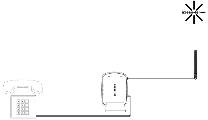
Setting up the Terminal
1. Connect the antenna by screwing into the TNC connector of the back of the terminal.
2. Connect an analog phone or cordless telephone to the terminal using an RJ-11 cord.
NOTE: Use the wire landline telephone compatible to FCC part 68 only. Non-compliant phones may
not work properly.
TX240G User Manual Ver. 0.2
6
3. Plug the AC adapter jack into the DC 5V jack of the Terminal.
4. Plug the AC adapter plug into an appropriate electrical outlet.
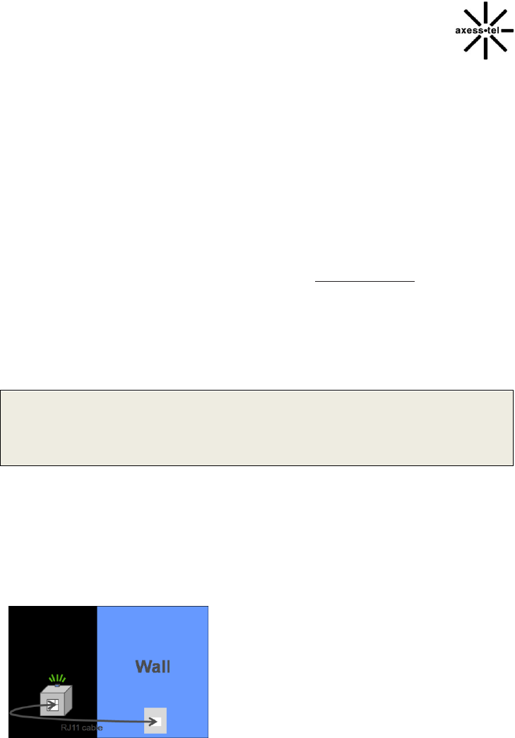
Connecting the terminal to home phone wall outlet.
5. TX240 can be connected to the home wall phone jack to allow users to use phones from any home
wall jack if the home wall phone jacks do not have existing service and are not powered. Before
connecting the terminal to home wall jack, please make sure that the home wall jacks are not live and
do not have any power. To test, please see the next section, “Wall Jack Tester”.
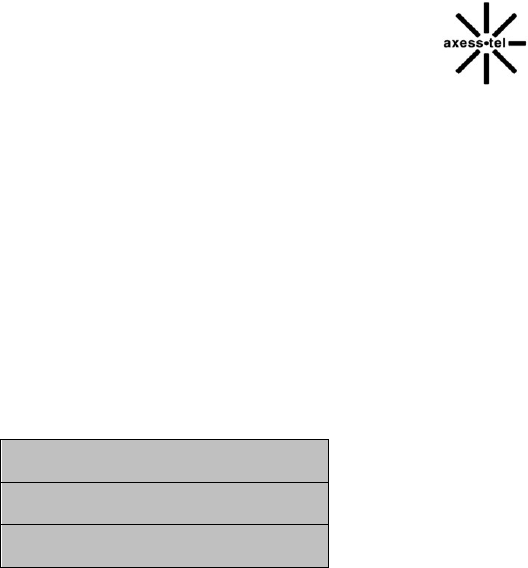
WALL JACK TESTER (PSTN Tester)
Optional wall jack tester check if the wall phone jack is powered by existing or previous landline phone
service.
IMPORTANT NOTE
DO NOT CONNECT YOUR TERMINAL TO WALL JACK IF PSTN LINE IS STILL IN SERVICE.
Connecting the terminal to the live wall jack may interfere with the existing phone service and/or
damage the terminal.
1. Plug the tester into the wall jack.
2. If tester’s Green colored LED turns on, PSTN line is still live and powered. In this case contact
you rexisting or previous landline phone service provider to disconnect the power. Alternately, 2-line
cross adapter may be used to bypass the powered first phone line (pin 2 and 3) if the second line (pin
1 and 4) is not powered.
3. If Green colored LED does not turn on, wall phone jack is not powered and you can safely connect
your terminal to wall jack.
TX240G User Manual STD Ver. 0.2
7
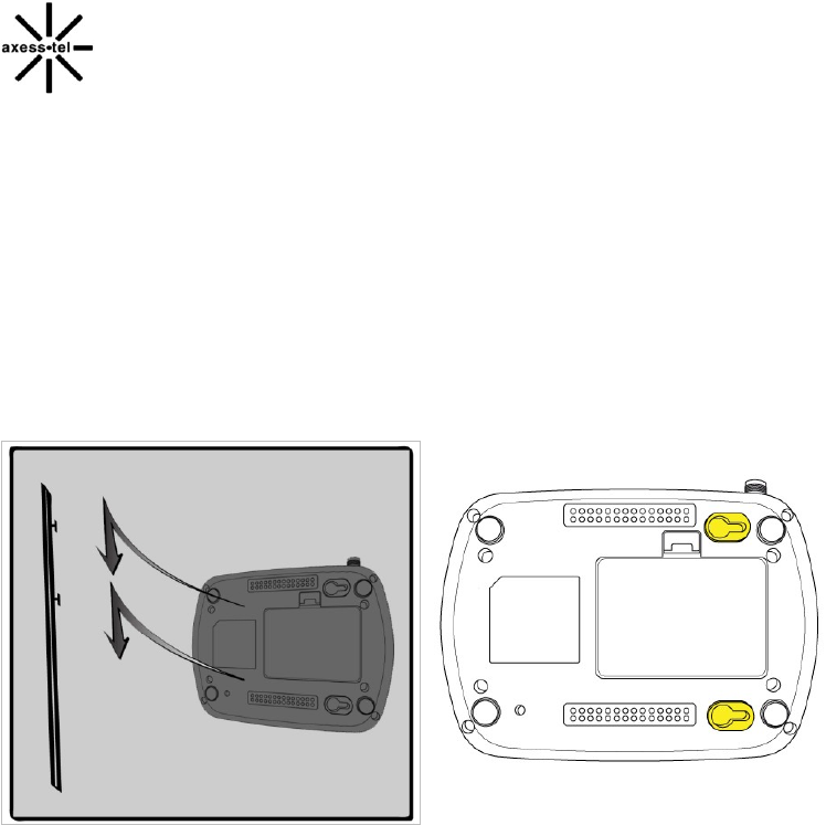
WALL MOUNT INSTALLATION
1. Mark two mounting holes’ locations to match the screw hole in the back of the terminal.
2. Drill two holes at the marked locations.
3. Tighten the screws until the head is about 5mm from the wall.
4. Plug in the power connector and route the cord in the groove, if needed.
5. Screw the antenna into antenna connector.
6. Hang the terminal on the screw using the two holes in the back.
7. Push the terminal down until the unit is firmly locked into place.
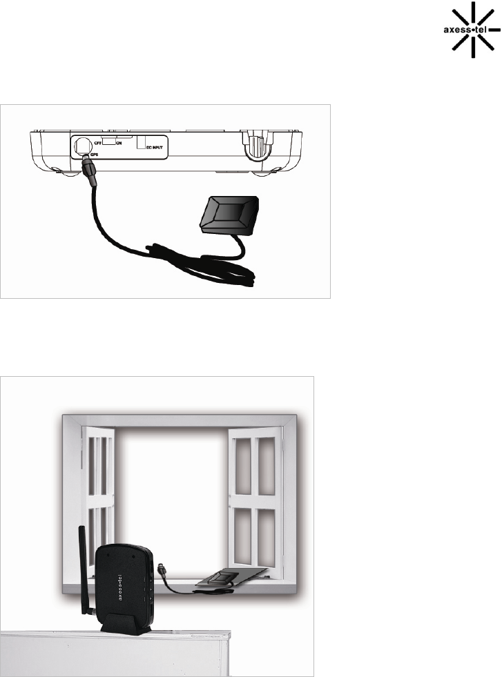
A-GPS for E911
Your terminal supports AGPS feature to meet U.S. FCC 911 mandate making the location of a
terminal available for callers in emergency situations. During the emergency call, all the LEDs on the
terminal blink and your location can determined by the service provider.. In order to increase the
location accuracy, the external GPS antenna must be connected to and positioned at a location that
can receive satellite signals, such as outside the building or near the windows.
TX240G User Manual Ver. 0.2
8
1. Connect the antenna to the GPS SMA connector on the terminal.
2. Place the Magnetic Pad at a location that has no obstruction to the sky, such as outdoor or windows.
3. Put the A-GPS antenna on the magnetic pad and position the antenna to face outside.
Note: Any obstruction to sky will degrade the GPS signal and degrade location accuracy.
TX240G User Manual STD Ver. 0.2
9
GETTING TO KNOW THE TERMINAL
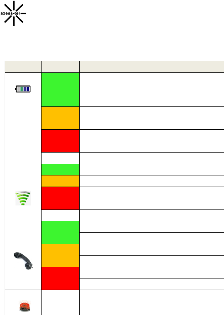
LED INDICATORS
Item
Color
Status
Description
Power
Green
Solid
In Battery Mode: Fully Charged
In Adaptor mode: Connected
Blinking
Charging
Orange
Solid
Mid Battery Level
Blinking
Battery Error
Red
Solid
Low Battery
Blinking
Low Battery Warning
Off
-
No Battery
Signal
Green
Solid
Excellent Signal
Orange
Solid
Good Signal
Red
Solid
Low Signal
Blinking
Limited Service
OFF
-
No service
Mode
Green
Solid
Off-Hook or In Use
Blinking
Incoming Call
Orange
Solid
-
Blinking
Voice Mail Waiting
Red
Solid
-
Blinking
-
E911 Call
All LEDs
Blinking
-All LEDs blink during emergency call
TX240G User Manual Ver. 0.2
10
Basic Operation
POWER ON/OFF
MAKING CALLS
RECEIVING CALLS

TX240G User Manual STD Ver. 0.2
11
POWER ON / OFF
Power switch is located on the back side of the terminal
1. Turn on the unit by moving switch to ON position.
2. Turn off the unit by moving switch to OFF position.
NOTE: When you turn on the terminal, it automatically searches for service signal.
After successfully acquiring service signal, the Signal LED turns to Green, Orange or
Red depending on signal strength.
MAKING CALLS
1. Check if the terminal is turned on.
2. Pick up the handset of the phone.
3. If you hear the dial tone, dial the desired telephone number by, using the analog phone or cordless
phone keypad.
Note : Dial number of maximum 32 digits, including * and #, can be entered.
4. Wait for about 3 seconds until the call is automatically made by the terminal. (Auto dial time can
be configured from 3 seconds to 9 seconds, or off)
Note: Press <#> button to make call right away after entering the dial number.
5. When the other recipient answers, begin conversation.
Note: If Connection Alert is turned on, a beep is heard when the call is connected.
6. To hang up, put the phone receiver back on the phone or press TALK or OFF button on your phone.
RECEIVING CALLS
The analog phone or cordless telephone(s) connected to the terminal ring when an incoming
call come in.
1. Pick up the telephone receiver to answer the call.
2. To disconnect after finished, replace the handset on the phone.
Note: If using cordless phone, press TALK or ON button to answer the phone call. Refer to analog

TX240G User Manual Ver. 0.2
12
phone or cordless phone user manual for instruction.
Note 1: Make sure that the attached telephone’s ringer is enabled.
Note 2: When there is an incoming call when you are already holding the receiver, press any
key on the numeric keypad to answer the call.

TX240G User Manual STD Ver. 0.2
13
Advanced Features
Sound
Adjusting Voice Volume
Adjusting Alert Volume
Setting One Minute Alert
Setting Voice Privacy Alert
Setting Connection Alert
General
Setting Caller ID
Setting Auto Send Time
Setting DTMF Length
Security
Changing Lock Code
Restricting Ongoing Calls
Factory Reset
TTY/TDD
Mode Setting

TX240G User Manual Ver. 0.2
14
ADJUSTING VOICE VOLUME
You can control the volume level of the terminal
1. Pick up the handset and check the dial-tone.
2. Press <*><*><1><1><*> to raise the voice volume
3. Press <*><*><1><1><#> to lower the voice volume
4. A confirmation beep will sound for 3 seconds
Note1: Some telephones may have their own volume control. Use both the terminal and the
telephone volume controls to optimize the sound level.
Note2: Volume can not be adjusted while conversation is in progress.
ADJUSTING ALERT TONE VOLUME
1. Pick up the handset.
2. Press <*><*><1><2><*> to raise the alert tone volume.
3. Press <*><*><1><2><*> to lower the alert tone volume.
SETTING ONE MINUTE ALERT
When this feature is enabled, a discrete tone is generated at each one minute interval
on the receiver during conversation for both incoming and outgoing calls. This tone is
to help the user keep track of the phone usage.
To change the setting,
1. Pick up the handset.
2. Press <*><*><1><3><#> to enable the feature.
3. Press <*><*><1><3><*> to disable the feature..
SETTING VOICE PRIVACY ALERT
If enabled, beep is generated when Voice Privacy is on.
To change the setting:
1. Pick up the handset.
2. Press <*><*><1><4><#> to enable the feature.
3. Press <*><*><1><4><*> to disable the feature..
SETTING CONNECTION ALERT

TX240G User Manual STD Ver. 0.2
15
If enabled, a discrete tone is generated on the receiver when the call is connected.
To change the setting:
1. Pick up the handset.
2. Press <*><*><1><5><#> to enable the feature.
3. Press <*><*><1><5><*> to disable the feature..
NOTE: The default setting may depends on the service provider.
SETTING CALLER ID MODE
If your phone connected to the terminal is caller ID enabled, you can set the terminal
to display the caller identification number or name on the LCD display of the analog phone.
1. Pick up the handset.
2. Press <*><*><2><1><0><#> to disable the Caller ID feature.
3. Press <*><*><2><1><1><#> to enable DTMF Standard Type.
4. Press <*><*><2><1><2><#> to enable FSK (Bellcore) type.
NOTE: The default setting of Caller ID is FSK.
SETTING AUTOSEND TIME
Similar to landline phone, the terminal automatically makes the call after short time the user
finishes entering dial numbers. To change,
1. Pick up the handset.
2. Press <*><*><2><2>. Then press <3>~<9> or <0> and press<#>
For example, to set 5 seconds, press <*><*><2><2><5><#>.
Note1: 0 disables auto-send. If diabled, the user must press <#> to make a call. <#> functions as
SEND key on the mobile phone. If auto-send time is 0, # as SEND feature is automatically enabled.
Note2: Default auto send time is 3 seconds.
Using # as SEND key
Similar to mobile phones, # key pressed after entering the dial numbers can act as SEND key.
This feature can be enabled of disabled.
1. Pick up the handset.
2. Press <*><*><2><3><#> to enable the feature.
3. Press <*><*><2><3><*> to disable the feature.
Note: Default setting is ON. If the Auto-Send Time is set as 0, the # as SEND is automatically enabled.

TX240G User Manual Ver. 0.2
16
SETTING DTMF LENGTH
Some ARS (Automatic Response Service) require short or long DTMF tones depending on the
system.
1. Pick up the handset.
2. Press <*><*><2><3><#> to select Short DTMF tone.
3. Press <*><*><2><3><*> to select Long DTMF tone.
CHANGING LOCK CODE
The lock code prevents the terminal from being used by unauthorized person without
permission. The default lock code is 0000
To change the lock code:
1. Pick up the handset.
2. Press <*><*><3><1>.
3. Enter old 4 digits lock code. For example <0><0><0><0>. A short beep will sound as confirmation. If
not correct, error tone will sound and the terminal returns to standby mode.
4. Enter new 4 digits lock code followed by <#>. For example <1><2><3><4><#>. Another short beep
sounds as confirmation.
5. Re-enter 4 digits lock code followed by <#>. For example <1><2><3><4><#>. Another beep
sounds as confirmation. If not correct, error tone will sound and the terminal returns to
standby mode.
For example, to change the lock code from 0000 to 1234, press
<*><*><3><1> .<0><0><0><0> <1><2><3><4><#> <1><2><3><4><#>.
RESTRICTING OUTGOING CALLS
This feature can be used block outgoing calls from being made. Incoming call can be received.
1. Pick up the handset.
2. Press <*><*><3><2>.
3. Enter 4 digits lock code.
4. Press <#> to enable or <*> to disable.
Note 1: Default lock code is <0><0><0><0>. To change, refer to “Changing Lock Code”
Note 2: If someone tries to make a call when outgoing call restriction is enabled, the terminal
sounds beep and howler tone.

TX240G User Manual STD Ver. 0.2
17
FACTORY RESET
Reset the user configuration to factory default settings
1. Pick up the handset.
2. Press <*><*><3><5>.
3. Enter 4 digit lock code. If not correct, error tone will sound and the terminal returns standby
mode.
4. Press <#> to reset.
Note 1: Default lock code is <0><0><0><0>. To change, refer to “Changing Lock Code”
Note2: Factory reset includes auto send time, lock code, call restrictions, caller ID type, voice privacy
alert, connection alert and 1 minute alert.
TTY/TDD
To use TTY/TDD feature, refer to following instruction. Default is OFF.
1. Connect the TTY/TDD phone to the terminal by RJ-11.
2. Lift the handset.
3. Press <*><*><5><1><0><#> for TTY Full Mode
4. Press <*><*><5><1><1><#> for TTY Talk Mode.
5. Press <*><*><5><1><2><#> for TTY Hear Mode.
6. Press <*><*><5><1><3><#>
Note: For the detailed instruction, contact your service provider.
TX240G User Manual Ver. 0.2
18
Optional Features
CALL WAITING
THREE-WAY CALLING
CALLER ID (Type I and II)
VOICE MAIL SERVICE
RJ11 CROSS ADAPTOR
CALL WAITING
Call Waiting is a feature, which enables you to be alerted to a second incoming call
while you are on the first call of your telephone. Your service provider may or may not provide
this feature. Please inquire your service provider.
1. You will hear a beep from the earpiece when a second call is incoming.
2. Press the hook shortly or press FLASH key to answer to the second call.
3. Press the hook again or press FLASH key to return to the first call.
THREE-WAY CALLING
Three-Way Calling is a feature that enables you to set up a three-way conversation
with two other users. Your service provider may or may not provide this feature. Please
inquire your service provider.
1. Place a call.
2. Press the hook shortly or press FLASH key and place another call.
3. When the second call is answered, press the hook briefly or press FLASH key to start a three-way
call.

TX240G User Manual STD Ver. 0.2
19
CALLER ID (Type I and II with CNAM – Network dependant feature)
To configure this feature, please refer to Setting Caller ID section in the Advanced Feature section
Default is 32 bytes and Type II Caller ID allows you to see the Caller ID of second caller waiting.
Alphanumeric caller ID will be supported if service provider’s network supports this feature and you
use alphanumeric caller ID supportable Landline phone.
VOICE MAIL SERVICE
When you receive voice message(s), the Mode LED will blink in orange color. When you lift the
receiver, voice message stutter tone is heard. Once your voice messages are checked and deleted,
LED turns off after few seconds.voice mail feature may not be part of your service. Please check with
your service provider.
Accessing your Voice Mail service
Please check with your service provider for the access number.
Clearing Voice Mail:
After calling the voice mail access number, please follow the instruction to set-up, listen and delete
voice messages.
RJ-11 CROSS ADAPTOR (Line 1 to Line 2 bypass adaptor)
If the first line (pin 2 and 3) of the phone line is live an has power, you may still be able to use the
terminal through your house phone wiring by using a set of RJ-11 cross adaptor. Cross adaptor uses
the Pin 1 and 3 of the RJ-11 cable. It must be used in pair or more, on each wall outlet. Depending
on your house wiring, second line may not be available or bothe line 1 and line 2 are powered. In this
case, do not connect the terminal to your home wall jack. Connect the POTS analog phone or
cordless phone directly to the terminal.
TX240G User Manual Ver. 0.2
20
Note1: Cross Adaptor may be called 2-line splitter and should be available from local electronic shops.

TX240G User Manual STD Ver. 0.2
21
Miscellaneous
MENU OPTION TABLE
TROUBLESHOOTING
SPECIFICATIONS

TX240G User Manual Ver. 0.2
22
MENU OPTION TABLE
MENU
("**○○")
Sub Menu ITEM
EXAMPLE
1.Sound
1. Adjusting Voice
Volume
<*> Louder
<#> Lower
<*><*><1><1><*> (louder)
<*><*><1><1><#> (lower)
2. Adjusting Alert
Volume
<*> Louder
<#> Lower
<*><*><1><2><*> (louder)
<*><*><1><2><#> (lower)
3. Setting 1 Minute
Alert
<*> Off
<#> On
<*><*><1><3><*> (off)
<*><*><1><3><#> (on)
4. Voice Privacy
Alert
<*> Off
<#> On
<*><*><1><4><*> (off)
<*><*><1><4><#> (on)
5. Connection
Alert
<*> Off
<#> On
<*><*><1><5><*> (off)
<*><*><1><5><#> (on)
2. General
1. Setting Caller ID
0: No Caller ID
1: DTMF Standard
2: FSK(Bellcore):Default
<*><*><2><1><0><#> (no caller id)
<*><*><2><1><1><#> (DTMF)
<*><*><2><1><2><#> (FSK)
2. Setting Auto Send
time
3~9 seconds
0: OFF
<*><*><2><2><3><#> (3 seconds)
<*><*><2><2><0><#> (off)
3. '#' as Send key
<*>Off
<#> On
<*><*><2><3><*>(off)
<*><*><2><3><#>(on)
4. Setting DTMF Length
<*>Long
<#> Short
<*><*><2><4><*> (Long)
<*><*><2><4><#> (Short)
3. Security
1. Changing Lock code
Old lock code,(Tone),
New lock code,(#),
New lock code again,(#)
To change from “0000” to “1234”
<*><*><3><1><0><0><0><0>
(confirm tone)
<1><2><3><4><#><1><2><3><4><#>
2. Restricting
Outgoing Calls
Lock code +
<*>Off or <#>On
If lock code is <0><0><0><0>, press
<*><*><3><2><0><0><0><0><*>(off)
<*><*><3><2><0><0><0><0><#>(on)
3. Factory Reset
Lock code, <#>
If lock code is <0><0><0><0>:
<*><*><3><5><0><0><0><0><#>
4.TTY
1. TTY Mode Set
0 : TTY_FULL
1 : TTY_TALK
2 : TTY_HEAR
3 : TTY_OFF (Default)
<*><*><4><1><0><#> : TTY_FULL
<*><*><4><1><1><#> : TTY_TALK
<*><*><4><1><2><#> : TTY_HEAR
<*><*><4><1><3><#> : TTY Off
5. A GPS
Test
Mode
1. Operation Mode
1 : Standalone
2 : MS-Based
3 : MS-Assisted
<#><#><4><7><7><#><1><1><#> :
Standalone
<#><#><4><7><7><#><1><2><#> :
MS-Based
<#><#><4><7><7><#><1><3><#> :
MS-Assisted
2. Get Position
<#><#><4><7><7><#><2><#>
3. Accuracy Threshold
<#><#><4><7><7><#><3><#>
TX240G User Manual STD Ver. 0.2
23
4. End Session
<#><#><4><7><7><#><4><#>
5. Set Session Type
1 : Set Single Session
2 : Set Tracking Session
<#><#><4><7><7><#><5><0><#> :
Single Session
<#><#><4><7><7><#><5><1><#> :
Tracking Session
TROUBLESHOOTING
Troubleshoot the conventional wired telephone
In the event you are unable to place or receive telephone calls, first be sure that the connection
wire is properly connected to the RJ-11 phone port on the terminal and to the RJ-11 port of the
telephone. If unsure whether or not the telephone is operational, connect a telephone,
which is known to be operational to the terminal. If service is available with the operational
telephone, replace or repair your telephone equipment. If service is still not available, then
follow instructions under "Troubleshoot the Fixed Wireless Terminal".
Troubleshoot the Fixed Wireless Terminal
Check for the appropriate power indication on the LED. If no power, check the adaptor
(or External Power Supply) connection between the electrical outlet and the terminal.
Check for the appropriate Received Signal Strength Indication (RSSI), Power, and Message
Indication through the designated LED, respectively.

TX240G User Manual Ver. 0.2
24
SPECIFICATIONS
Item
Description
Remark
Air Interface
CDMA20001x
RF Frequency
800MHz/1900Mhz
Dual band
LED Indicator
3 multi color
Power, Signal Mode
Green, Orange, Red, Off
Interface
- 2 RJ-11 Ports, bridged (Max 5 REN)
- DC Input Jack
- Power ON/OFF Switch
- TNC Connector for CDMA antenna
- SMA Connector for GPS antenna
- RUIM(Optional)
Battery
- Li-ion rechargeable battery
- Capacity :1000mAh (Standard)
* Stand by time: 7Hrs
* Talk time:1Hr
Power Adapter
- Input: AC100-240V, 50/60Hz
- Output:5V/2A
Dimension
- Size: 165 X 117.5 X31 (mm)
- Weight: 268g
With standard battery
Operating
condition
- Temperatue: -10℃ ~ 50℃
- Relative humidity : 10~95%
- Air pressure : 86~106kpa
AXESSTEL INC.
6815 Flanders Drive Ste. 210
San Diego, CA 92121, USA
www.axesstel.com
© Axesstel Inc, All Rights Reserved
Safety Information
1 . SAFETY INFORMATION FOR FIXED WIRELESS TERMINALS
.POTE NTIALLY EXPLOSIVE ATMOSPHERES
Turn your phone OFF when in any area with a potentially explosive atmosphere and
obey all signs and instructions. Sparks in such areas could cauls e an explosion or fire
resulting in bodily injury or even death.
INTERFERENCE TO MEDICAL DIVICES
Certain electronic equipment may be shielded against RF signal from you wireless
phone. (pacemakers, Hearing Aids, and so on) Turn your phone OFF in health c are
facilities when any regulations posted in these areas instruct you to do so. RF signals
may affect improperly installed or inadequately shielded electronic system in motor
vehicles.
.EXPOSURE TO RF ENERGY
Use only the supplied or an approved replacement antenna. Do not touch the antenna
unnecessarily when the phone is in use. Do not move the antenna close to, or
couching any exposed part of the body when making a call.

SAR INFORMATION
THIS MODEL PHONE MEETS THE GOVERNMENT’S
REQUIREMENTS FOR EXPOSURE TO RADIO WAVES.
Your wireless phone is a radio transmitter and receiver. It is designed and manufactured not to
exceed the emission limits for exposure to radiofrequency (RF) energy set by the Federal
Communications Commission of the U.S. Government. These limits are part of comprehensive
guidelines and establish permitted levels of RF energy for the general population. The guidelines
are based on standards that were developed by independent scientific organizations through
periodic and thorough evaluation of scientific studies. The standards include a substantial safety
margin designed to assure the safety of all persons, regardless of age and health. The exposure
standard for wireless mobile phones employs a unit of measurement known as the Specific
Absorption Rate, or SAR. The SAR limit set by the FCC is 1.6 W/kg. *
Tests for SAR are conducted with the phone transmitting at its highest certified power level in all
tested frequency bands. Although the SAR is determined at the highest certified power level, the
actual SAR level of the phone while operating can be well below the maximum value. This is
because the phone is designed to operate at multiple power levels so as to use only the power
required to reach the network. In general, the closer you are to a wireless base station antenna, the
lower the power output. Before a phone model is available for sale to the public, it must be tested
and certified to the FCC that it does not exceed the limit established by the government adopted
requirement for safe exposure. The tests are performed in positions and locations (e.g., at the ear
and worn on the body) as required by the FCC for each model. The highest SAR value for this
model phone when tested for use at the ear is 1.33 W/Kg. SAR information on this model phone is
on file with the FCC and can be found under the Display Grant section of http://www.fcc.gov/
oet/fccid after searching on FCC ID: PH7TX240G.
Additional information on Specific Absorption Rates (SAR) can be found on the Cellular
Telecommunications Industry Asso-ciation (CTIA) web-site at http://www.wow-com.com. * In the
United States and Canada, the SAR limit for mobile phones used by the public is 1.6 watts/kg
(W/kg) averaged over one gram of tissue. The standard incorporates a sub-stantial margin of safety
to give additional protection for the public and to account for any variations in measurements.
Near Body operation
This device was tested for typical near body operations with the back of the phone kept 20 mm from
the body. To maintain compliance with FCC RF exposure requirements, it must have a minimum
distance including the antenna of 2 cm from the body during normal operation.
U.S.A.
U.S.FEDERAL COMMUNICATIONS COMMISSION
RADIO FREQUENCY INTERFERENCE STATEMENT
INFORMATION TO THE USER
NOTE : This equipment has been tested and found to comply with the limits for a Class B
digital device pursuant to Part 15 of the FCC Rules. These limits are designed to provide
reasonable protection against harmful Interference in a residential installation This equipment
generates, uses, and can radiate radio frequency energy and, if Not installed and used in
accordance with the instructions, may cause harmful Interference to radio communications.
However, there is no guarantee that interference will not occur in a particular Installation. If this
equipment does cause harmful interference to radio or television reception, which can be
determined by turning the equipment off and on, the user is encouraged to try to correct the
interference by one or more of the following measures:
*- Reorient or relocate the receiving antenna.
Increase the separation between the equipment and receiver.
*- Connect the equipment into an outlet of a circuit different from that to which the receiver is
connected.
*- Consult the dealer or an experienced radio/TV technician for assistance.
Changes or modification not expressly approved by the party responsible for Compliance
could void the user’s authority to operate the equipment. Connecting of peripherals requires
the use of grounded shielded signal cables.
FCC Compliance Information
This device complies with Part 15 of FCC Rules.
Operation is subject to the following two conditions:
(1) This device may not cause harmful interference, and
(2) This device must accept any interference received.
Including interference that may cause undesired operation.

TX240G User Manual STD Ver. 0.2
25