Axon Enterprise S00831 Axon Signal Unit User Manual Manual
TASER International Axon Signal Unit Manual
Contents
- 1. User Manual
- 2. Manual
Manual
Axon Signal Unit
Installation Manual
Page 1 of 9
Introduction
The Axon Signal Unit (ASU) is part of a communications platform that interacts with an
emergency vehicle’s light bar. When the light bar activates, all properly equipped Axon Flex
systems within range begin recording.
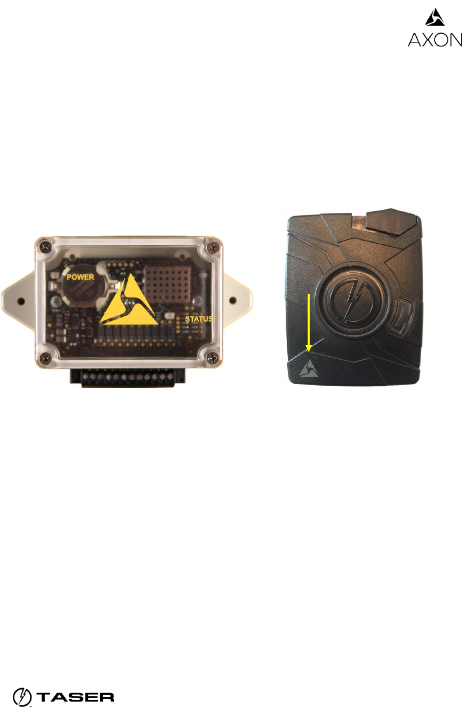
For automatic recording to occur, an Axon Flex camera must be attached to an Axon Flex
controller equipped with Axon Signal technology. A controller equipped with this technology has
an Axon logo on the lower-left side of the front of the device. See the TASER Axon Flex System
User Manual for more information.
Axon Signal Unit Axon Flex controller with Axon Signal technology
Failure to follow the instructions in this manual may result in the ASU not working
properly or cause damage to the ASU or the vehicle. Save these instructions.
The technician who installs the ASU must be qualified to work with automotive
electronics.
When installing the ASU, ensure that drilling will not damage the emergency vehicle’s
equipment or surface. Remove all burrs and debris after drilling.
Ensure there is a good electrical ground to the vehicle chassis.
Do not install the ASU anywhere that will interfere with airbag deployment.
Do not install the ASU where it will be exposed to the elements or extreme heat. Do not
install the ASU in the vehicle’s engine compartment.
Characteristics
Secure Bluetooth broadcast (30 seconds).
Activates all enabled cameras in range (30+ feet/9.1+ meters).
Axon Signal Unit
Installation Manual
Page 2 of 9
The ASU only causes an Axon Flex system to transition from BUFFERING to EVENT mode.
You end the recording with a 3-second press of the EVENT button on the Axon Flex controller.
Double-pressing the EVENT button on the Axon Flex controller after the EVENT mode is
activated by the Axon Signal Unit will not interfere with recording.
Installation Instructions
Axon Signal Units are usually installed near the siren box or light bar controller (trunk or
console).
Clean the surface before installation.
The ASU can be mounted using robust double-sided tape, Velcro, or bolting tools (bolts
not included).
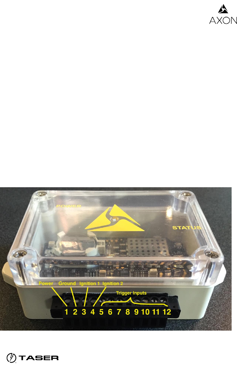
Wires should be connected to the GPIO terminal block interface.
Wires should be no smaller than 18 gauge.
1A fuse is recommended, either in line or on a fuse block.
No programming of the box is required, just installation.
Inputs and respective locations are outlined in the picture below.
Axon Signal Unit
Installation Manual
Page 3 of 9
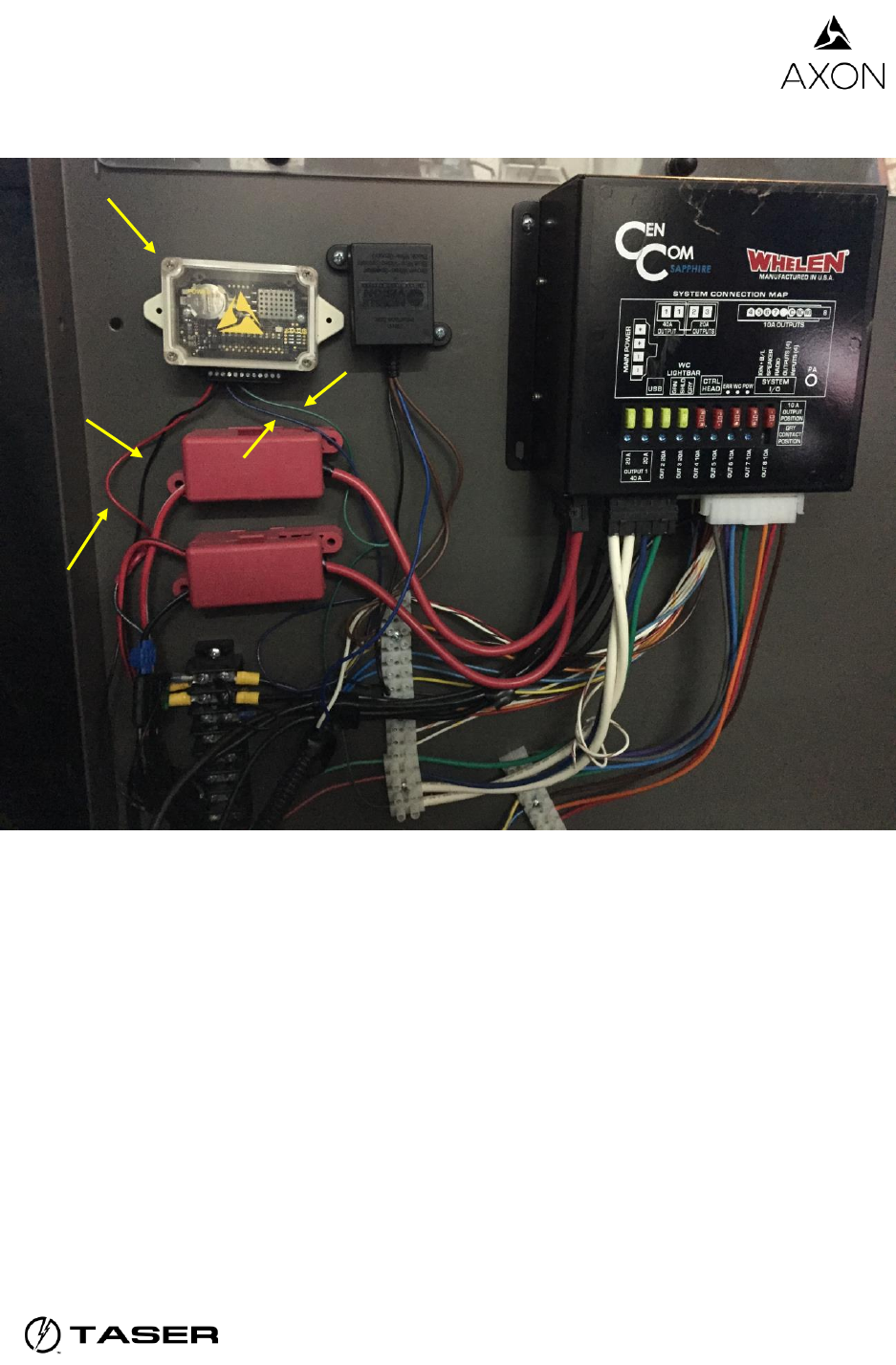
An ASU installed in an emergency vehicle.
The most important things to installing your Axon Signal Unit are:
Locating the vehicle electronics.
Identifying the trigger (for an ASU installation, this would be the light bar), power, and
ignition wires.
Connecting the ASU to ground.
Step 1: Locate the Electronics
The first step to installing the Axon Signal system is locating the wiring for your vehicle.
Generally, the wiring is found in the trunk, up against the back of the rear seat, in the console
under your light bar controller, or in a box designated specifically for electronics (mostly for
motorbikes).
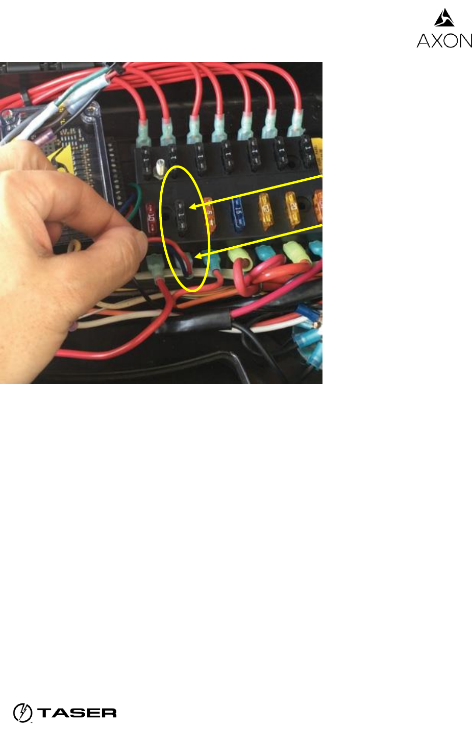
Step 2: Locate the Trigger Wiring
Once you have located the electronics you must determine which wire is connecting to the
trigger that will activate your Axon products. To identify the correct wire:
ASU
Trigger wire
Power wire
Ground wire
Ignition wire
Axon Signal Unit
Installation Manual
Page 4 of 9
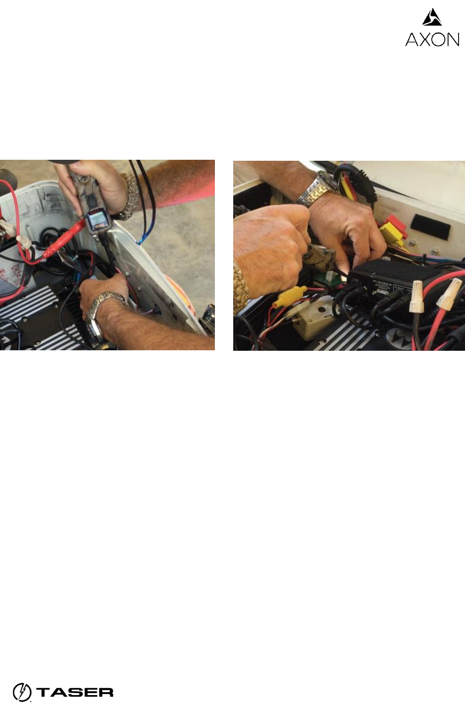
1. Turn on the trigger (that is, turn on the light bar).
2. Use a voltmeter to test the wires that might be connected to the trigger.
When you make contact with the correct wire, the voltmeter will indicate its activity.
3. Turn the trigger off and verify that the voltage drops to zero; then you know you have
located your trigger wire.
Step 3: Locate Power and Ignition Wiring
After locating and connecting the trigger wire, you must do the same for the power and ignition.
Often, the vehicle’s battery will be hooked up to a timed relay. If it is, you may run power and
ignition wires into the same position and place a 1-ampere fuse in line.
Note: Both power and ignition inputs on the Axon Signal Unit must be used for the device to
work properly. In some cases (e.g., when you are using a timed relay), the inputs come
from the same source. Standard setup, you need to identify both power (hot) and
ignition.
Axon Signal Unit
Installation Manual
Page 5 of 9
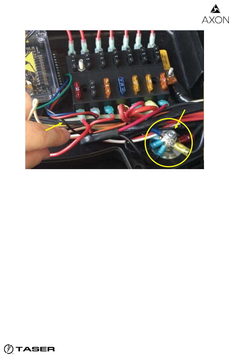
Step 4: Run the Ground Wire to the Ground Position
Finally, you will need to connect the Axon Signal Unit to ground.
1. Locate the ground wire.
2. Connect it to a grounded location in the electronics area.
1 Amp fuse
Power and ignition
Axon Signal Unit
Installation Manual
Page 6 of 9
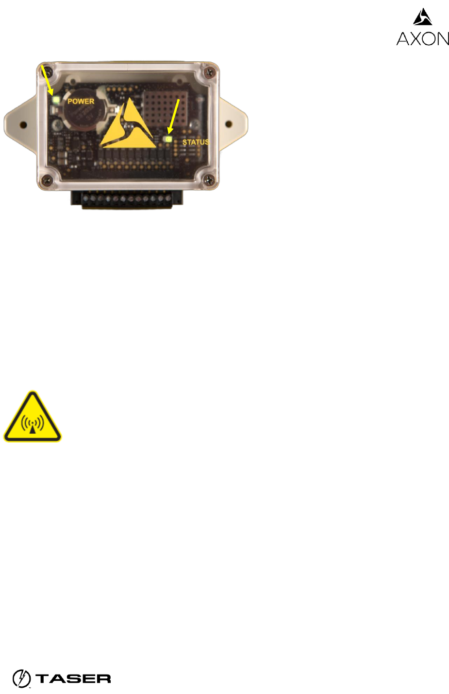
Step 5: Verify the Axon Signal Unit Is Working
It is recommended that you test your signal unit to make sure it is functional.
1. Start the vehicle’s engine.
2. Look at the ASU.
A green POWER light indicates the ASU is powered up.
A green STATUS light indicates a successful startup.
o If both lights are on, your ASU is ready and working properly.
o If either light is not on, try turning the engine off and restarting it. If both lights do not
turn on, remove the power wire from slot 1 and plug it back in. If either light remains
off, contact TASER customer service.
Ground
wire
Ground
Axon Signal Unit
Installation Manual
Page 7 of 9
3. Turn on the trigger (for example, turn on your vehicle’s light bar).
4. Listen for the two beeps that indicate your Axon Flex system now is in EVENT mode.
Troubleshooting
If you finish the installation and the power and status lights do not turn on, the vehicle’s breaker
switch might not be turned on. Flip the breaker switch and repeat the instructions in Step 5:
Verify the Axon Signal Unit Is Working.
If this does not work, there may be an issue with the wiring.
Radio Waves
Changes or modifications to the equipment not expressly approved by the manufacturer could
void the product warranty and the user’s authority to operate the equipment.
Your wireless device is a radio transmitter and receiver. It is designed and manufactured not to
exceed the emission limits for exposure to radio frequency (RF) energy set by the Federal
Communications Commission (FCC) of the U.S. Government. These limits are part of
comprehensive guidelines and establish permitted levels of RF energy for the general
population. The guidelines are based on standards that were developed by independent
scientific organizations through periodic and thorough evaluation of scientific studies. The
standards include a substantial safety margin designed to ensure the safety of all persons,
regardless of age and health. Before a device model is available for sale to the public, it must be
tested and certified to the FCC that it does not exceed the limit established by the government‐
adopted requirement for safe exposure.
This equipment has been tested and found to comply with the limits for a Class B digital device,
pursuant to part 15 of the FCC Rules. These limits are designed to provide reasonable
Axon Signal Unit
Installation Manual
Page 8 of 9
protection against harmful interference in a residential installation. This equipment generates,
uses and can radiate radio frequency energy and, if not installed and used in accordance with
the instructions, may cause harmful interference to radio communications. However, there is no
guarantee that interference will not occur in a particular installation. If this equipment does
cause harmful interference to radio or television reception, which can be determined by turning
the equipment off and on, the user is encouraged to try to correct the interference by one or
more of the following measures:
Reorient or relocate the receiving antenna.
Increase the separation between the equipment and receiver.
Connect the equipment into an outlet on a circuit different from that to which the receiver is
connected.
Consult TASER International Customer Service for help.
This device complies with Part 15 of the FCC Rules. Operation is subject to the following two
conditions:
1. This device may not cause harmful interference, and
2. This device must accept any interference received, including interference that may cause
undesired operation.
To comply with FCC RF exposure limits for general population / uncontrolled exposure, the
antenna(s) used for this transmitter must be installed to provide a separation distance of at least
20 cm from all persons and must not be co-located or operating in conjunction with any other
antenna or transmitter.
Section 7.1.3 of RSS-GEN
This Device complies with Industry Canada License-exempt RSS standard(s). Operation is
subject to the following two conditions: 1) this device may not cause interference, and 2) this
device must accept any interference, including interference that may cause undesired operation
of the device.
Section 7.1.3 de RSS-GEN
Cet appareil est conforme aux normes d’exemption de licence RSS d’Industrie Canada. Son
utilisation est soumise aux conditions suivantes : 1) cet appareil ne doit pas causer de
brouillage, et 2) doit accepter tout brouillage, y compris le brouillage pouvant entraîner un
fonctionnement indésirable.
Section 7.1.2 of RSS-GEN
Under Industry Canada regulations, this radio transmitter may only operate using an antenna of
a type and maximum (or lesser) gain approved for the transmitter by Industry Canada. To
reduce potential radio interference to other users, the antenna type and its gain should be so
chosen that the equivalent isotropically radiated power (e.i.r.p.) is not more than that necessary
for successful communication.
Axon Signal Unit
Installation Manual
Page 9 of 9
To comply with IC RF exposure limits for general population / uncontrolled exposure, the
antenna(s) used for this transmitter must be installed to provide a separation distance of at least
20 cm from all persons and must not be co-located or operating in conjunction with any other
antenna or transmitter.
Section 7.1.2 de RSS-GEN
Conformément à la réglementation d’Industrie Canada, le présent émetteur radio ne peut
fonctionner qu’au moyen d’une antenne d’un seul type et d’un gain maximal (ou inférieur)
approuvé pour l’émetteur par Industrie Canada. Dans le but de réduire les risques de brouillage
radioélectrique pour les autres utilisateurs, il faut choisir le type d’antenne et son gain de sorte
que la puissance isotrope rayonnée équivalente (p.i.r.e.) ne dépasse pas celle requise pour
établir une communication satisfaisante.
Pour se conformer aux limites d’exposition aux radiofréquences fixées par Industrie Canada
relativement aux limites d’exposition humaine, l’antenne utilisée pour cet émetteur doit être
installée à une distance d’au moins 20 cm de toutes les personnes et ne doit pas être installée
ou exploitée conjointement avec d’autres antennes ou émetteurs.
RSS 210 Warning Statement: The installer of this equipment must ensure that the antenna is
located or pointed such that it does not emit RF field in excess of Health Canada limits for the
general population; consult Safety Code 6, obtainable from Heath Canada’s Web site www.hc‐
sc.gc.ca/rpb.
Bluetooth is a trademark of the Bluetooth SIG, Inc., and Velcro is a trademark of Velcro Industries B.V.
, AXON, Axon Flex, Axon Signal, TASER, and © are trademarks of TASER International, Inc., some of which are registered in
the US and other countries. For more information, visit www.TASER.com/legal. All rights reserved. © 2015 TASER International,
Inc.
MMU0060 Rev: A