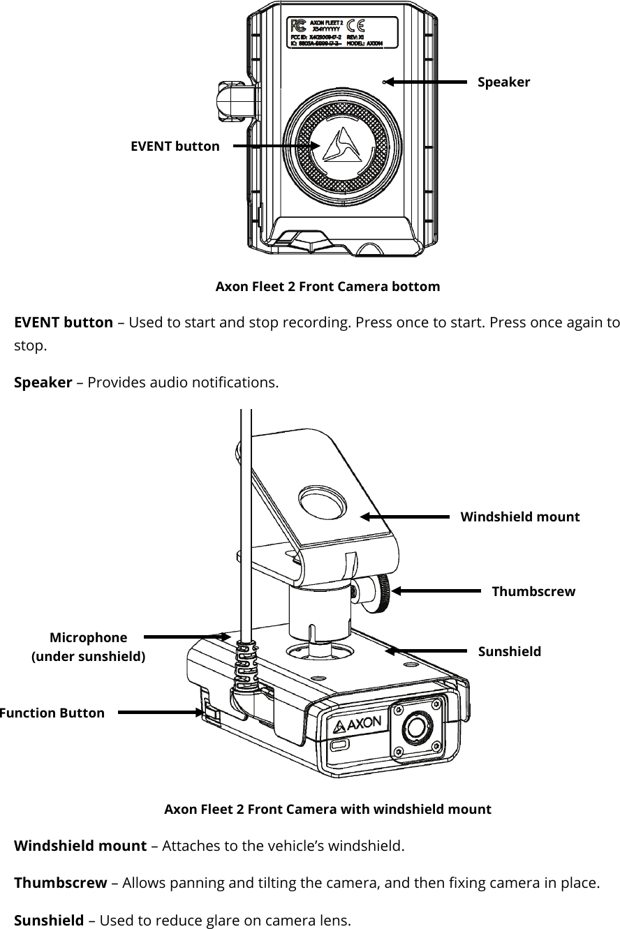
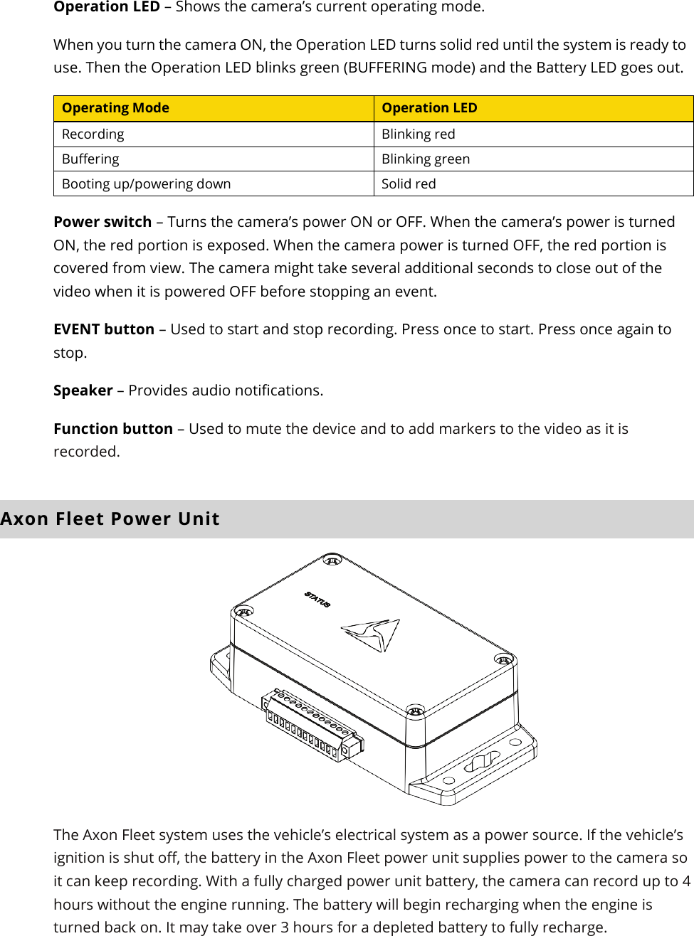
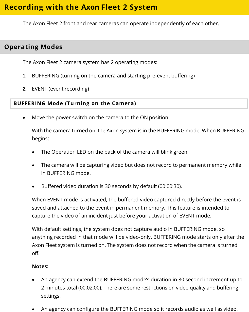
Axon Enterprise S00947B Axon Fleet 2.0 Front Camera User Manual Axon Fleet 2 Camera

Axon Enterprise, Inc Axon Fleet 2.0 Front Camera Axon Fleet 2 Camera

User Manual

 Axon Fleet 2 Camera System User Manual Document Revision: BETA-I July 2018
Axon Fleet 2 Camera System     User Manual Axon Enterprise, Inc.       Page 2 of 22  Apple, iOS, and Safari are trademarks of Apple, Inc. registered in the US and other countries. Firefox is a trademark of The Mozilla Foundation registered in the US and other countries. Google, Google Play, Android, and Chrome are trademarks of Google, Inc. Microsoft, Azure, Windows, Internet Explorer, and Excel are trademarks of Microsoft Corporation registered in the US and other countries. Javascript is a trademark of Oracle America, Inc. registered in the US and other countries. ,  Axon, Axon Fleet 2, Evidence.com, Evidence.com Lite, Evidence Sync, and TASER are trademarks of Axon Enterprise, Inc., some of which are registered in the US and other countries. For more information, visit www.axon.com/legal.  All rights reserved. ©2018 Axon Enterprise, Inc.
Axon Fleet 2 Camera System     User Manual Axon Enterprise, Inc.       Page 3 of 22 Table of Contents Introduction................................................................................................................................................. 4 Additional Reading ..................................................................................................................................... 4 Getting to Know Your Axon Fleet 2 Camera System ............................................................................... 6 Axon Fleet 2 Front Camera Hardware ..................................................................................................... 6 Axon Fleet Rear Camera Hardware ......................................................................................................... 9 Axon Fleet Power Unit ............................................................................................................................. 11 Recording with the Axon Fleet 2 System ................................................................................................ 12 Operating Modes ..................................................................................................................................... 12 BUFFERING Mode (Turning on the Camera) ................................................................................ 12 EVENT Mode (Starting Recording) .................................................................................................. 13 Muting Audio Recording .......................................................................................................................... 14 Adding Markers while Recording ........................................................................................................... 14 Zoom Function.......................................................................................................................................... 14 Axon Signal ................................................................................................................................................ 15 Notification Reference Tables ................................................................................................................. 17 Audio Prompts .......................................................................................................................................... 17 LED Status ................................................................................................................................................. 17 Operation LED .................................................................................................................................. 17 Function LED ..................................................................................................................................... 17 Uploading Video from the Axon Fleet 2 System .................................................................................... 18 Wireless via LTE ........................................................................................................................................ 18 Wireless at Station ................................................................................................................................... 18 USB Cable .................................................................................................................................................. 18 Troubleshooting and Other Information ............................................................................................... 19 Customer Service ..................................................................................................................................... 19 Warranty Policy......................................................................................................................................... 19 Declaration of Conformity ...................................................................................................................... 19 Warnings ................................................................................................................................................... 19 Compliance Marks ................................................................................................................................... 20 Radio Waves .............................................................................................................................................. 20
Axon Fleet 2 Camera System     User Manual Axon Enterprise, Inc.       Page 4 of 22 Introduction The Axon Fleet 2 solution is a camera system incorporating an audio and video recording device. This camera is designed for use in tough environmental conditions encountered in law enforcement, corrections, military, and security activities. The Axon Fleet 2 system is designed to record events for secure storage, retrieval, and analysis using Evidence.com services. The recorded events can be transferred wirelessly to the Evidence.com website through Wi-Fi technology. You also can transfer information by using Evidence Sync software installed on a Windows computer.  The Axon Fleet 2 system usually consists of 2 cameras: one installed in the front of the vehicle in a windshield mount, and the second pointed at the law enforcement vehicle’s prisoner compartment. The Axon Fleet 2 system cameras have 2 operating modes designed to accommodate the needs of law enforcement, corrections, security, and the military. The default mode, or BUFFERING mode, which provides pre-event buffering to capture activities that occur prior to activating cameras, and EVENT mode, which records events. If the Axon Fleet 2 system is used in an emergency vehicle equipped with an Axon Signal Vehicle unit, the camera will transition from BUFFERING to EVENT mode when an appropriate event occurs (such as your emergency vehicle’s light bar being activated). The camera is normally powered by the vehicle. If the vehicle’s ignition is shut off, an inline Axon Fleet power unit provides power for up to 4 hours of recording. Additional Reading This manual explains how to operate the Axon Fleet 2 camera hardware. Other manuals cover additional aspects of the Axon Fleet system. These documents are available at www.axon.com. The Axon View XL Manual provides instructions for using your mobile data terminal (MDT) with your Axon Fleet system. For information on managing users, managing vehicles, managing Fleet camera settings, and working with videos, see the Evidence.com User and Administrator Reference Guide.  Detailed instructions for using Axon cameras and other Axon products with Evidence Sync are available in the Evidence Sync User Manual.
Axon Fleet 2 Camera System     User Manual Axon Enterprise, Inc.       Page 5 of 22 The Axon Academy website explains how to register for the Evidence.com website, configure settings, assign personnel to cameras, and transfer video from an Axon device to a computer. Visit academy.axon.com.
Axon Fleet 2 Camera System     User Manual Axon Enterprise, Inc.       Page 6 of 22 Getting to Know Your Axon Fleet 2 Camera System Although your Axon Fleet system can be configured for automated transfer from BUFFERING to EVENT mode under the right conditions, both the front and rear cameras still include physical controls to enable video and audio recording. The cameras also provide visual and audible notification of the Axon Fleet system’s state of operation. Note: Many of the features activated by the buttons below also can be activated with the Axon View XL program. See the Axon View XL Manual for more information. Axon Fleet 2 Front Camera Hardware  The following images show the different components on the Axon Fleet 2 front camera, Model AX1014.   Axon Fleet 2 Front Camera front Swivel ball joint – Attaches camera to camera mount  Power cable – Provides power from Axon Fleet Power Unit  Lens – The camera lens.  Operation indicator – Shows camera operation. Blinking green = BUFFERING mode, blinking red = EVENT (recording) mode Swivel ball joint Lens Power cable Operation indicator
Axon Fleet 2 Camera System     User Manual Axon Enterprise, Inc.       Page 7 of 22  Axon Fleet 2 Front Camera back Function LED – Shows camera functions that are enabled.  Function Enabled Function LED Mute Blinking blue Camera error* Solid red Bluetooth feature is booting up Solid blue Camera is searching for Wi-Fi Blinking magenta Camera connected to Wi-Fi Solid magenta * Use the power switch to turn the camera OFF and ON. Operation LED – Shows the camera’s current operating mode. When you turn the camera ON, the Operation LED turns solid red until the system is ready to use. Then the Operation LED blinks green (BUFFERING mode) and the Battery LED goes out. Operating Mode Operation LED Recording  Blinking red Buffering  Blinking green Booting up/powering down Solid red Dataport – Used for data transfer through PC when using Evidence Sync Power switch – Turns the camera’s power ON or OFF. When the camera’s power is turned ON, the red portion is exposed. When the camera power is turned OFF, the red portion is covered from view. The camera might take several additional seconds to close out of the video when it is powered OFF before stopping an event. Operation LED Power switch Function LED Dataport
Axon Fleet 2 Camera System     User Manual Axon Enterprise, Inc.       Page 8 of 22  Axon Fleet 2 Front Camera bottom  EVENT button – Used to start and stop recording. Press once to start. Press once again to stop.  Speaker – Provides audio notifications.  Axon Fleet 2 Front Camera with windshield mount Windshield mount – Attaches to the vehicle’s windshield. Thumbscrew – Allows panning and tilting the camera, and then fixing camera in place.  Sunshield – Used to reduce glare on camera lens.  Speaker EVENT button Function Button Windshield mount Sunshield Thumbscrew Microphone (under sunshield)
Axon Fleet 2 Camera System     User Manual Axon Enterprise, Inc.       Page 9 of 22 Function button – Used to mute the device and to add markers to the video as it is recorded. Microphone – For recording in-cabin audio. Located under the sunshield.  Axon Fleet Rear Camera Hardware The following images show the different components on the Axon Fleet 2 rear camera, Model AX1015, and rear camera controller, Model AX1016.      Axon Fleet 2 rear camera and mount  Lens – The camera lens.  Camera mount – Attaches camera to the vehicle. Ambient light sensor – Engages infra-red (IR) illumination at low ambient light.  IR illumination window – Infra-red (IR) illumination source.  Camera cable – Connects the camera to the camera controller.  Angle adjustment screws – Allows tilting the camera and then fixing camera in place. Microphone – For recording in-cabin audio. Located on the back of the rear camera.   Camera cable IR illumination window Ambient light sensor Lens Camera mount Angle adjustment screws  Microphone  (on back of camera)
Axon Fleet 2 Camera System     User Manual Axon Enterprise, Inc.       Page 10 of 22  Axon Fleet 2 rear camera controller and mount  Camera cable – Connects the camera to the camera controller. Camera controller – The Axon Fleet 2 rear camera controller includes physical controls to enable video and audio capture while providing visual and audible notifications of the camera’s state of operation. Controller mount – Used to mount the camera controller to the vehicle and provides power to the controller and rear camera.  Function LED – Shows camera functions that are enabled.  Function Enabled Function LED Mute Blinking blue Camera error* Solid red Bluetooth feature is booting up Solid blue Camera is searching for Wi-Fi Blinking magenta Camera connected to Wi-Fi Solid magenta * Use the power switch to turn the camera OFF and ON. Controller mount Function button Camera controller Camera cable Speaker EVENT Button Function LED Power switch Operation LED
Axon Fleet 2 Camera System     User Manual Axon Enterprise, Inc.       Page 11 of 22 Operation LED – Shows the camera’s current operating mode. When you turn the camera ON, the Operation LED turns solid red until the system is ready to use. Then the Operation LED blinks green (BUFFERING mode) and the Battery LED goes out. Operating Mode Operation LED Recording  Blinking red Buffering  Blinking green Booting up/powering down Solid red Power switch – Turns the camera’s power ON or OFF. When the camera’s power is turned ON, the red portion is exposed. When the camera power is turned OFF, the red portion is covered from view. The camera might take several additional seconds to close out of the video when it is powered OFF before stopping an event. EVENT button – Used to start and stop recording. Press once to start. Press once again to stop.  Speaker – Provides audio notifications.  Function button – Used to mute the device and to add markers to the video as it is recorded. Axon Fleet Power Unit  The Axon Fleet system uses the vehicle’s electrical system as a power source. If the vehicle’s ignition is shut off, the battery in the Axon Fleet power unit supplies power to the camera so it can keep recording. With a fully charged power unit battery, the camera can record up to 4 hours without the engine running. The battery will begin recharging when the engine is turned back on. It may take over 3 hours for a depleted battery to fully recharge.
Axon Fleet 2 Camera System     User Manual Axon Enterprise, Inc.       Page 12 of 22 Recording with the Axon Fleet 2 System The Axon Fleet 2 front and rear cameras can operate independently of each other.  Operating Modes The Axon Fleet 2 camera system has 2 operating modes: 1. BUFFERING (turning on the camera and starting pre-event buffering) 2. EVENT (event recording) BUFFERING Mode (Turning on the Camera) • Move the power switch on the camera to the ON position. With the camera turned on, the Axon system is in the BUFFERING mode. When BUFFERING begins: • The Operation LED on the back of the camera will blink green. • The camera will be capturing video but does not record to permanent memory while in BUFFERING mode.  • Buffered video duration is 30 seconds by default (00:00:30). When EVENT mode is activated, the buffered video captured directly before the event is saved and attached to the event in permanent memory. This feature is intended to capture the video of an incident just before your activation of EVENT mode. With default settings, the system does not capture audio in BUFFERING mode, so anything recorded in that mode will be video-only. BUFFERING mode starts only after the Axon Fleet system is turned on. The system does not record when the camera is turned off. Notes: • An agency can extend the BUFFERING mode’s duration in 30 second increment up to 2 minutes total (00:02:00). There are some restrictions on video quality and buffering settings.  • An agency can configure the BUFFERING mode so it records audio as well as video.
Axon Fleet 2 Camera System     User Manual Axon Enterprise, Inc.       Page 13 of 22 EVENT Mode (Starting Recording) To begin recording, do one of the following: • Use the Axon View XL application to start recording. • Press the EVENT button on the camera/controller. • If your vehicle has an Axon Signal Vehicle unit, your camera will transition from BUFFERING to EVENT mode when the Axon Signal Vehicle unit sends a signal. When your camera starts recording, you will hear 2 beeps. The system now records audio as well as video. The “buffered” video directly preceding the event is saved and attached to the event recording (Note: With default settings, the buffered video does not contain audio). The moment EVENT mode begins, both video and audio are recorded from the camera and GPS coordinates are recorded (Note: GPS coordinates are provided by the router). This will continue throughout the duration of the recording until you stop the recording.  The camera provides you with indications that it is recording in EVENT mode: • At the start of an event and every 2 minutes during an event, the system beeps twice. • The Operation LED on the camera or controller blinks red.  1. To stop recording and return to BUFFERING mode:  • Use the Axon View XL application to stop recording, or • Press the EVENT button. The system will beep once (with a long tone). 2. To turn off the system, move the power switch to the OFF position. When you end a recording with the power switch you will not go into BUFFERING mode; instead the system will turn off completely. Note: An event not recorded by the camera cannot be played back or downloaded to your computer.
Axon Fleet 2 Camera System     User Manual Axon Enterprise, Inc.       Page 14 of 22 Muting Audio Recording You can use the function button to disable audio recording during an event if your administrator has configured your Axon Fleet 2 system to do so. This feature may be useful in sensitive situations.  You can also use the View XL audio controls to mute and enable audio recordings.  1. Press and hold the Function button on the camera/controller for 3 seconds to mute the audio recording. The camera will beep twice and the Function LED will blink blue while the camera is muted.  2. Press and hold the Function button on the camera/controller another 3 seconds to re-enable the audio recording. Adding Markers while Recording The Function button can be used to add a marker while recording video. The marker is shown when the video is replayed in Evidence.com and documented in the audit trail. Markers are useful for indicating an important event that you want to easily find when replaying the video.  To add a marker to a video while you are recording:  • Press and release the Function button within 1 second.  Zoom Function  The Axon Fleet 2 Front Camera is equipped with a zoom function. This function allows you to magnify the center portion of the front camera’s view while using Live View. The zoom function works in both BUFFERING and EVENT modes.  1. In the View XL Control tab, tap Live View.  2. On the Live View, check that the Front camera is selected.
Axon Fleet 2 Camera System     User Manual Axon Enterprise, Inc.       Page 15 of 22 3. Tap anywhere on the screen to magnify.   The magnification returns to normal after 10 seconds.  You can tap anywhere on the screen a second time to return to normal magnification before the 10 second timeout. 4. Tap Close to return to the Control tab  Axon Signal Axon Signal technology is included with the Axon Fleet system. However, your agency’s Evidence.com administrator must activate the Axon Signal capability for it to work. When it is active, Axon Signal technology can take your Axon Fleet system from BUFFERING to EVENT mode. Emergency vehicles can be equipped with an Axon Signal Vehicle unit. When triggered, such as by a light bar activation, the Axon Signal Vehicle unit sends a signal to your Axon Fleet system. Upon receiving this signal, your Axon cameras transition from BUFFERING to EVENT mode. When your camera starts recording, you will hear 2 beeps.  The Axon Signal Vehicle unit has a range of approximately 30 feet (9.1 meters). Axon Signal technology can only send a signal to tell the camera to start recording. Axon Signal technology does not end recording. for example, if a light bar is turned off, the camera will continue to record until the user stops the recording.  Tap anywhere on the screen to magnify
Axon Fleet 2 Camera System     User Manual Axon Enterprise, Inc.       Page 16 of 22 The Axon Signal technology cannot turn an Axon system on. If the Axon Fleet system is turned off, the camera will not record even if an Axon Signal Vehicle unit sends a trigger signal.
Axon Fleet 2 Camera System     User Manual Axon Enterprise, Inc.       Page 17 of 22 Notification Reference Tables Audio Prompts The Axon Fleet system emits beeping sounds called “audio prompts” to notify you of the system status. These audio prompts usually occur after a camera action.  Operating Mode Audio Notification Powering on or off One beep Recording an event Two beeps (repeats every 2 minutes) Enter or exit Mute mode Two beeps The device is ending an event and returning to BUFFERING mode One long beep The camera is running off the Axon Fleer power unit (the car ignition is off) and the battery is at 20% capacity or lower.  Four quick beeps (every 5 minutes) The camera memory is full (the camera will not start recording). Three beeps.  LED Status  Operation LED The operation LED displays the system’s current operating mode. Operating Mode Operation LED Recording  Blinking red Buffering  Blinking green Booting up/powering down Solid red  Function LED The function LED displays when certain functions are enabled: Function Enabled Function LED Mute Blinking blue Camera error* Solid red Bluetooth feature is booting up Solid blue Camera is searching for Wi-Fi Blinking magenta Camera connected to Wi-Fi Solid magenta * Use the power switch to turn the camera OFF and ON.
Axon Fleet 2 Camera System     User Manual Axon Enterprise, Inc.       Page 18 of 22 Uploading Video from the Axon Fleet 2 System The Axon Fleet system can support the multiple offload options listed below: Wireless via LTE The Axon Fleet system can upload video via Long Term Evolution (LTE), a fast wireless service, if the vehicle has an in-car router that supports LTE. For more information, see the Axon View XL Manual.  Wireless at Station An agency can equip its parking facilities with wireless access points so that vehicles equipped with Axon Fleet systems can upload their videos. For more information, see the Axon View XL Manual. Note: There might be additional system requirements associated with Wi-Fi offload. USB Cable If Evidence Sync software is installed on your computer, you can download information from an Axon Fleet 2 camera to your computer and upload the information to the Evidence.com website. For more information, see the Evidence Sync User Manual.
Axon Fleet 2 Camera System     User Manual Axon Enterprise, Inc.       Page 19 of 22 Troubleshooting and Other Information  • If you have trouble with your Axon Fleet system cameras, turn the camera off and turn it on again. • If you receive camera status errors in View XL, refer to the Axon View XL Manual for troubleshooting information.  • If the camera is not transitioning to EVENT mode from Axon Signal Vehicle triggers, have an Evidence.com administrator verify the Signal Configuration set up is correct in Evidence.com.  • If the previous actions do not resolve the difficulties, contact Axon Customer Service for additional support. Customer Service Visit www.axon.com and view the Support options, or call 1-800-978-2737. Warranty Policy Axon Enterprise warranty provisions are applicable on all Axon Fleet system products. See Axon Enterprise’s website, www.axon.com, for detailed warranty information. Declaration of Conformity  Axon declares that this Axon system is compliant with the requirements of the Radio Equipment Directive (RED) 2014/53/EU. A copy of the original Declaration of Conformity can be found at www.axon.com.  Warnings For a full list of the warning associated with this product, see www.axon.com.
Axon Fleet 2 Camera System     User Manual Axon Enterprise, Inc.       Page 20 of 22 Compliance Marks          Radio Waves  An Axon Fleet 2 system transmission is in the frequency ranges of 2402 – 2480 MHz, 2412 – 2462 MHz, and 5745 – 5825 MHz.  Changes or modifications to the equipment not expressly approved by the manufacturer could void the product warranty and the user’s authority to operate the equipment. Your wireless device is a radio transmitter and receiver. It is designed and manufactured not to exceed the emission limits for exposure to radio frequency (RF) energy set by the Federal Communications Commission (FCC) of the U.S. Government. These limits are part of comprehensive guidelines and establish permitted levels of RF energy for the general population. The guidelines are based on standards that were developed by independent scientific organizations through periodic and thorough evaluation of scientific studies. The standards include a substantial safety margin designed to assure the safety of all persons, regardless of age and health. Before a device model is available for sale to the public, it must be tested and certified to the FCC that it does not exceed the limit established by the government-adopted requirement for safe exposure. This equipment has been tested and found to comply with the limits for a Class B digital device, pursuant to part 15 of the FCC Rules. These limits are designed to provide reasonable protection against harmful interference in a residential installation. This equipment generates, uses and can radiate radio frequency energy and, if not installed and used in accordance with the instructions, may cause harmful interference to radio communications. However, there is no guarantee that interference will not occur in a particular installation. If this equipment does cause harmful interference to radio or television reception, which can be determined by turning the equipment off and on, the user is encouraged to try to correct the interference by one or more of the following measures:  • Reorient or relocate the receiving antenna.  • Increase the separation between the equipment and receiver.  • Connect the equipment into an outlet on a circuit different from that to which the receiver is connected.  • Consult Axon International Customer Service for help.
Axon Fleet 2 Camera System     User Manual Axon Enterprise, Inc.       Page 21 of 22 This device complies with part 15 of the FCC Rules. Operation is subject to the following two conditions: (1) This device may not cause harmful interference, and (2) this device must accept any interference received, including interference that may cause undesired operation.  This device complies with Industry Canada licence-exempt RSS standard(s). Operation is subject to the following two conditions: (1) this device may not cause interference, and (2) this device must accept any interference, including interference that may cause undesired operation of the device.  Le présent appareil est conforme aux CNR d’Industrie Canada applicables aux appareils radio exempts de licence. L’exploitation est autorisée aux deux conditions suivantes : (1) l’appareil ne doit pas produire de brouillage, et (2) l’utilisateur de l’appareil doit accepter tout brouillage radioélectrique subi, même si le brouillage est susceptible d’en compromettre le fonctionnement.  THIS MODEL DEVICE MEETS THE GOVERNMENT’S REQUIREMENTS FOR EXPOSURE TO RADIO WAVES.  Section 8.4 of RSS-GEN  This Device complies with Industry Canada License-exempt RSS standard(s). Operation is subject to the following two conditions: 1) this device may not cause interference, and 2) this device must accept any interference, including interference that may cause undesired operation of the device.  Cet appareil est conforme aux normes d’exemption de licence RSS d’Industrie Canada. Son utilisation est soumise aux conditions suivantes : 1) cet appareil ne doit pas causer de brouillage, et 2) doit accepter tout brouillage, y compris le brouillage pouvant entraîner un fonctionnement indésirable.  Section 8.3 of RSS-GEN  Under Industry Canada regulations, this radio transmitter may only operate using an antenna of a type and maximum (or lesser) gain approved for the transmitter by Industry Canada. To reduce potential radio interference to other users, the antenna type and its gain should be so chosen that the equivalent isotropically radiated power (e.i.r.p.) is not more than that necessary for successful communication.  Conformément à la réglementation d’Industrie Canada, le présent émetteur radio ne peut fonctionner qu’au moyen d’une antenne d’un seul type et d’un gain maximal (ou inférieur) approuvé pour l’émetteur par Industrie Canada. Dans le but de réduire les risques de brouillage radioélectrique pour les autres utilisateurs, il faut choisir le type d’antenne et son
Axon Fleet 2 Camera System     User Manual Axon Enterprise, Inc.       Page 22 of 22 gain de sorte que la puissance isotrope rayonnée équivalente (p.i.r.e.) ne dépasse pas celle requise pour établir une communication satisfaisante.  THIS MODEL DEVICE MEETS THE GOVERNMENT’S REQUIREMENTS FOR EXPOSURE TO RADIO WAVES Section 6.8 of RSS-GEN These radio transmitters IC: 8803A-S00947B and IC: 8803A-S00146B have been approved by Innovation, Science and Economic Development Canada to operate with the antenna types listed below, with the maximum permissible gain indicated. Antenna types not included in this list that have a gain greater than the maximum gain indicated for any type listed are strictly prohibited for use with this device. Axon Fleet 2.0 Front camera uses a stamped metal dual band dipole. Antenna gain is <5.8dBi at 2.4GHz, and <1.88dBi at 5.8GHz. The required impedance for this antenna is 50 ohms. Axon Fleet 2.0 Rear camera uses a ceramic chip dual band antenna. Antenna gain is  <-4.15dBi at 2.4GHz, and <-0.3dBi at 5.8 GHz. The required impedance for this antenna is 50 ohms.

Navigation menu