Axxcelera Broand Wireless APC4-365 ExelIMAX Access Point User Manual
Axxcelera Broadband Wireless, Inc. ExelIMAX Access Point Users Manual
Users Manual

ExcelMAX® Access Point
Cell Installation &
Maintenance Guide
Version 1.4 April 30, 2008
Copyright 2006-2008 Axxcelera All rights reserved.
Information Subject to Change without Notice
Axxcelera reserves the absolute right to make changes to the information set forth in this Product
Manual without notice. Specifications subject to change without notice. Customers may inquire as
to whether they have the most current Product Manual by contacting Axxcelera Technical Support
Department.
Proprietary Rights
Axxcelera, Axxcelera Broadband Wireless, and the Axxcelera logo are all trademarks of
Axxcelera. All other company and product names referenced herein are the trademarks of their
respective holders.
Axxcelera reserves all copyright, trademark, trade name, service mark, intellectual property,
proprietary and other rights to this Product Manual and the diagrams, schematics and all other
information contained herein, and nothing shall give Customer any legal, license or other interest
in the Product Manual or such diagrams, schematics or other information. Customer agrees not to
reproduce or copy by any means any portion of this Product Manual without Axxcelera’s prior
written permission in each case. Other than as expressly specified herein, Axxcelera grants no
license to Customer under any copyrights or other proprietary rights to use or reproduce any
portion of this Product Manual.
No Liability
Axxcelera makes no warranties with respect to this Product Manual of any kind. WITHOUT
LIMITATION, AXXCELERA DISCLAIMS ALL WARRANTIES; EXPRESS OR IMPLIED,
INCLUDING LIMITED WARRANTIES OF MERCHANTABILITY OR FITNESS FOR A
PARTICULAR PURPOSE, OR ARISING FROM A COURSE OF DEALING OR TRADE USAGE.
WITH RESPECT TO THIS PRODUCT MANUAL, IN NO EVENT SHALL AXXCELERA BE LIABLE
TO ANY THIRD PARTY FOR ANY DAMAGES, INCLUDING INDIRECT, INCIDENTAL, PUNITIVE
OR CONSEQUENTIAL DAMAGES, OR LIABILITY FOR LOSS OF DATA, LOSS OF PROFITS
OR ATTORNEY’S FEES, REGARDLESS OF THE FORM OF THE ACTION OR WHETHER
AXXCELERA HAS BEEN ADVISED OF THE POSSIBILITY OF SUCH DAMAGES.
LICENSE ISSUES
The OpenSSL toolkit stays under a dual license, i.e. both the conditions of the OpenSSL License
and the original SSLeay license apply to the toolkit. See below for the actual license texts. Actually
both licenses are BSD-style Open Source licenses. In case of any license issues related to
OpenSSL please contact openssl-core@openssl.org
OpenSSL License
Copyright (c) 1998-2003 The OpenSSL Project. All rights reserved.
Redistribution and use in source and binary forms, with or without modification, are permitted
provided that the following conditions are met:
1. Redistribution of source code must retain the above copyright notice, this list of conditions and
the following disclaimer.
2. Redistributions in binary form must reproduce the above copyright notice, this list of conditions
and the following disclaimer in the documentation and/or other materials provided with the
distribution.
3. All advertising materials mentioning features or use of this software must display the following
acknowledgement: “This product includes software developed by the OpenSSL Project for
use in the OpenSSL Toolkit. (http://www.openssl.org/)”
4. The names “OpenSSL Toolkit” and “OpenSSL Project” must not be used to endorse or
promote products derived from this software without prior written permission. For written
permission, please contact openssl-core@openssl.org.
5. Products derived from this software may not be called “OpenSSL” nor may “OpenSSL” appear
in their names without prior written permission of the OpenSSL Project.
6. Redistributions of any form whatsoever must retain the following acknowledgement: “This
product includes software developed by the OpenSSL Project for use in the OpenSSL Toolkit
(http://www.openssl.org/)”
THIS SOFTWARE IS PROVIDED BY THE OpenSSL PROJECT “AS IS” AND ANY EXPRESSED
OR IMPLIED WARRANTIES, INCLUDING, BUT NOT LIMITED TO, THE IMPLIED WARRANTIES
OF MERCHANTABILITY AND FITNESS FOR A PARTICULAR PURPOSE ARE DISCLAIMED. IN
NO EVENT SHALL THE OpenSSL PROJECT OR ITS CONTRIBUTORS BE LIABLE FOR ANY
DIRECT, INDIRECT, INCIDENTAL, SPECIAL, EXEMPLARY, OR CONSEQUENTIAL DAMAGES
(INCLUDING, BUT NOT LIMITED TO, PROCUREMENT OF SUBSTITUTE GOODS AND
SERVICES; LOSS OF USE, DATA, OR PROFITS; OR BUSINESS INTERRUPTION) HOWEVER
CAUSED AND ON ANY THEORY OF LIABILITY, WHETHER IN CONTRACT, STRICT LIABILITY,
OR TORT (INCLUDING NEGLIGENCE OR OTHERWISE) ARISING IN ANY WAY OUT OF THE
USE OF THIS SOFTWARE, EVEN IF ADVISED OF THE POSSIBILITY OF SUCH DAMAGE.
This product includes cryptographic software written by Eric Young (eay@cryptsoft.com). This
product includes software written by Tim Hudson (tjh@cryptsoft.com)
Original SSLeay License
Copyright (C) 1995-1998 Eric Young (eay@cryptsoft.com)
All rights reserved.
This package is an SSL implementation written by Eric Young (eay@cryptsoft.com). The
implementation was written so as to conform with Netscape SSL.
This library is free for commercial and non-commercial use as long as the following conditions are
adhered to. The following conditions apply to all code found in this distribution, be it the RC4, RSA,
lhash, DES, etc., code; not just the SSL code. The SSL documentation included with this
distribution is covered by the same copyright terms except that the holder is Tim Hudson
(tjh@cryptsoft.com).
Copyright remains Eric Young’s, and as such any Copyright notices in the code are not to be
removed. If this package is used in a product, Eric Young should be given attribution as the author
of the parts of the library used. This can be in the form of a textual message at program startup or
in documentation (online or textual) provided with the package.
Redistribution and use in source and binary forms, with or without modification, are permitted
provided that the following conditions are met:
1. Redistributions of source code must retain the copyright notice, this list of conditions and the
following disclaimer.
2. Redistributions in binary form must reproduce the above copyright notice, this list of conditions
and the following disclaimer in the documentation and/or other materials provided with the
distribution.
3. All advertising materials mentioning features or use of this software must display the following
acknowledgement: “This product includes cryptographic software written by Eric Young
(eay@cryptsoft.com).” The word ‘cryptographic’ can be left out if the rouines from the library
being used are not cryptographic related. :-)
4. If you include any Windows specific code (or a derivative thereof) from the apps directory
(application code) you must include an acknowledgement: “This product includes software
written by Tim Hudson (tjh@cryptsoft.com).”
THIS SOFTWARE IS PROVIDED BY ERIC YOUNG “AS IS” AND ANY EXPRESS OR IMPLIED
WARRANTIES, INCLUDING, BUT NOT LIMITED TO, THE IMPLIED WARRANTIES OF
MERCHANTABILITY AND FITNESS FOR A PARTICULAR PURPOSE ARE DISCLAIMED. IN NO
EVENT SHALL THE AUTHOR OR CONTRIBUTORS BE LIABLE FOR ANY DIRECT, INDIRECT,
INCIDENTAL, SPECIAL, EXEMPLARY, OR CONSEQUENTIAL DAMAGES (INCLUDING, BUT
NOT LIMITED TO, PROCUREMENT OF SUBSTITUTE GOODS OR SERVICES; LOSS OF USE,
DATA, OR PROFITS; OR BUSINESS INTERRUPTION) HOWEVER CAUSED AND ON ANY
THEORY OF LIABILITY, WHETHER IN CONTRACT, STRICT LIABILITY, OR TORT (INCLUDING
NEGLIGENCE OR OTHERWISE) ARISING IN ANY WAY OUT OF THE USE OF THIS
SOFTWARE, EVEN IF ADVISED OF THE POSSIBILITY OF SUCH DAMAGE.
The license and distribution terms for any publicly available version or derivative of this code
cannot be changed. i.e. this code cannot simply be copied and put under another distribution
license (including the GNU Public License).
TABLE OF CONTENTS
5 OF 65
1.0 Preface ..................................................................................................................................................7
1.1 Who Should Read This Manual ......................................................................................................7
1.2 Using This Guide .............................................................................................................................7
1.3 Conventions Used ...........................................................................................................................7
1.4 Related Documentation ...................................................................................................................7
1.5 Technical Support ..........................................................................................................................8
1.6 Sales ...............................................................................................................................................8
2.0 Introduction ..........................................................................................................................................9
2.1 ExcelMAX Access Point Packing List .............................................................................................9
2.2 ExcelMAX Access Point Overview ..................................................................................................9
2.2.1 ExcelMAX Access Point ........................................................................................................10
2.2.1.1 OPTIONAL: GPS Synchronization ...............................................................................12
2.3 Major Components ........................................................................................................................12
2.3.1 Indoor Equipment ..................................................................................................................12
2.3.1.1 AC NIA/Power Adapter .................................................................................................12
2.3.1.2 DC NIA/Power Adapter ................................................................................................13
2.3.2 Interconnecting cable ............................................................................................................14
2.3.3 Outdoor Equipment ...............................................................................................................15
3.0 Installation ..........................................................................................................................................16
3.1 Compliance Alert – Operation in the 3.4 - 3.6 GHz Band .............................................................16
3.2 Operation in the 3.650 - 3.675 GHz Band .....................................................................................16
3.2.1 FCC Information to Users @ FCC 15.21 & 15.105 ...............................................................16
3.2.2 Warning to Users @ FCC 15.21 & 15.105: ...........................................................................16
3.2.3 FCC Label @ FCC 15.19 ......................................................................................................17
3.2.4 RF EXPOSURE REQUIRMENTS @ 1.1310 & 2.1091 .........................................................17
3.3 Installation Warnings .....................................................................................................................17
3.4 Environmental Cautions ................................................................................................................17
3.5 Installing Outdoor Equipment ........................................................................................................18
3.5.1 Access Point Packing List .....................................................................................................18
3.5.2 Sector Antenna Packing List .................................................................................................18
3.5.3 Omnidirectional Antenna Packing List ..................................................................................18
3.5.4 Customer Supplied Equipment Required for Antenna Installation ........................................18
3.5.5 Antenna Site Requirements .................................................................................................18
3.5.6 Required Tools for Outdoor Installation ................................................................................19
3.5.7 Preparing to Mount the Antenna Brackets ............................................................................19
3.6 Installing an Optional Sector Antenna ...........................................................................................20
3.6.1 Grounding the Antenna Mounting .........................................................................................20
3.6.2 Attaching the Sector Antenna to the Mounting Points ..........................................................21
3.6.3 Attaching RF Cable to Access Point .....................................................................................29
3.6.4 Grounding the Cables ...........................................................................................................30
3.6.5 Waterproofing Cable Connections ........................................................................................30
3.7 Installing Optional Omnidirectional Antenna .................................................................................31
3.7.1 Grounding the Antenna Mounting .........................................................................................31
3.7.2 Installing the Omnidirectional Antenna .................................................................................31
3.7.3 Attaching RF Cable to Access Point .....................................................................................33
3.7.4 Grounding the Cables ...........................................................................................................33
3.7.5 Waterproofing Cable Connections ........................................................................................34
3.8 Installing the Access Point ............................................................................................................34
3.8.1 Mounting L-bracket to the Access Point ...............................................................................34
3.8.2 Mounting Access Point to the Pole .......................................................................................35
3.8.3 Aligning the Access Point .....................................................................................................36
3.8.4 Attaching the Ground Wire (recommended) ........................................................................37
3.8.5 Attaching the Cat-5 Cable ....................................................................................................38
3.9 Power and Data Connections – AC and DC Power Options .........................................................40
TABLE OF CONTENTS
6 OF 65
3.9.1 AC PSU/NIA Option ..............................................................................................................41
3.9.1.1 Connecting the Access Point to the AC Power Supply/NIA .........................................41
3.9.1.2 Completing the Connection of the AC Power Supply/NIA ..........................................42
3.9.2 DC PSU/NIA Option ..............................................................................................................45
3.9.2.1 Connecting the Access Point to the DC Power Supply/NIA ........................................46
3.9.2.2 Completing the Connection of the DC Power Supply/NIA ..........................................47
4.0 Configuring an Access Point for Single-Channel Use ...................................................................50
4.1 Logging into the Access Point Web Page .....................................................................................51
4.1.3 Configuring IP Address Settings ...........................................................................................53
4.1.4 Configuring System Information Settings .............................................................................54
4.1.5 Completing Access Point Setup ............................................................................................55
4.1.6 Power Settings for Operation in the 3.650 - 3.675 GHz Band ..............................................57
5.0 Maintenance Guide ............................................................................................................................59
A NIA/Power Adapter Specifications: Model # TR60A-POE-L .............................................................60
B ExcelMax DC PSU/NIA (020-44109-0802) ...........................................................................................61
C Glossary of Terms and Abbreviations ...............................................................................................62
Index ..........................................................................................................................................................64

EXCELMAX ACCESS POINT CELL INSTALLATION AND MAINTENANCE GUIDE VERSION 1.4
7 OF 65
1.0 Preface
The ExcelMAX Access Point Cell Installation and Maintenance Guide covers installation,
configuration and maintenance of the ExcelMAX Access Point Base Station.
This guide assumes a working knowledge of wireless technology and how to configure networking
systems.
1.1 Who Should Read This Manual
The ExcelMAX Access Point Cell Installation and Maintenance Guide is for Axxcelera trained or
authorized service personnel who need to install the ExcelMAX Access Point and configure it to
operate in a network environment.
1.2 Using This Guide
The ExcelMAX Access Point Cell Installation and Maintenance Guide explains how to install the
physical components and then configure them for use. It includes a maintenance section and
troubleshooting guidelines.
1.3 Conventions Used
This manual uses the following text formatting conventions:
• Bold Text indicates a specific module, field, window, or button.
• Italic Text highlights the name of other documents or references.
• Text in angle brackets indicates individual keystrokes. For example, <Enter>.
• Fixed width text identifies a specific file or directory.
1.4 Related Documentation
The following documents may also be useful:
• Access Point Manager User’s Guide
• CPE Manager User’s Guide
• ExcelMAX CPE Installation Guide
• Base Station Plan Editor User’s Guide
• Plan Concepts
Warning
Note
Tip
Hint
Text within boxes indicates warnings, notes, helpful tips and hints.
N
T
H

EXCELMAX ACCESS POINT CELL INSTALLATION AND MAINTENANCE GUIDE VERSION 1.4
8 OF 65
1.5 Technical Support
Axxcelera provides technical support to assist with any problems or to answer questions about
Axxcelera ExcelMAX solutions. The technical support staff is factory trained and equipped to
resolve questions about Axxcelera products.
1.6 Sales
You may contact the Sales Department for more information:
Telephone: +1 (804) 864-4222
Email: support@axxcelera.com
Web site: www.axxcelera.com
Telephone: +1 (480) 820-9270
Fax: +1 (480) 820-9275
Email: sales@axxcelera.com
Web site: www.axxcelera.com
EXCELMAX ACCESS POINT CELL INSTALLATION AND MAINTENANCE GUIDE VERSION 1.4
9 OF 65
2.0 Introduction
This chapter covers the following information:
• ExcelMAX Access Point Packing List
• ExcelMAX Access Point Overview
• Major Components
2.1 ExcelMAX Access Point Packing List
The Access Point kit includes:
• 1 Access Point
• 1 L-bracket
• 1 clamp
• 1 U-bolt
• 1 PG-11 cable gland
• 1 PG-11 cable gland o-ring
• 1 ground lug
• 5 hex head bolts, M6 x 16 mm Lg
• 5 M6 split lock washers
• 1 M6 flat washer
• 2 M6 serrated flange nut
• GPS antenna (optional)
• 1 AC or DC NIA/Power Adapter (power cable not included, supplied by the service provider*)
* AC power cables are included
2.2 ExcelMAX Access Point Overview
ExcelMAX Access Points contain modem and radio circuitry that connects to an external
sectorized or omnidirectional antenna. The antenna is designed for mounting on a standard
communications tower or on a building rooftop, and requires minimal “real estate.” The Access
Point connects to the local network device (switch/router) via a standard 10/100BaseT interface.
The antenna is connected to the Access Point via 50-ohm low loss coaxial cable.
Some ExcelMAX Access Points also contain GPS circuitry that connects to a separate supplied
external antenna (supplied by Axxcelera). The antenna is designed for mounting on a standard
communications tower or on a building rooftop, and requires minimal “real estate.”
The ExcelMAX Management System is typically located at the customer Network Operating
Center (NOC), and allows complete control of the Axxcelera ExcelMAX system singly or in a
network environment
EXCELMAX ACCESS POINT CELL INSTALLATION AND MAINTENANCE GUIDE VERSION 1.4
10 OF 65
2.2.1 ExcelMAX Access Point
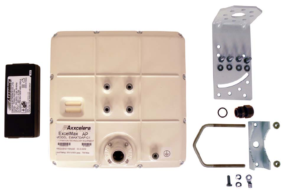
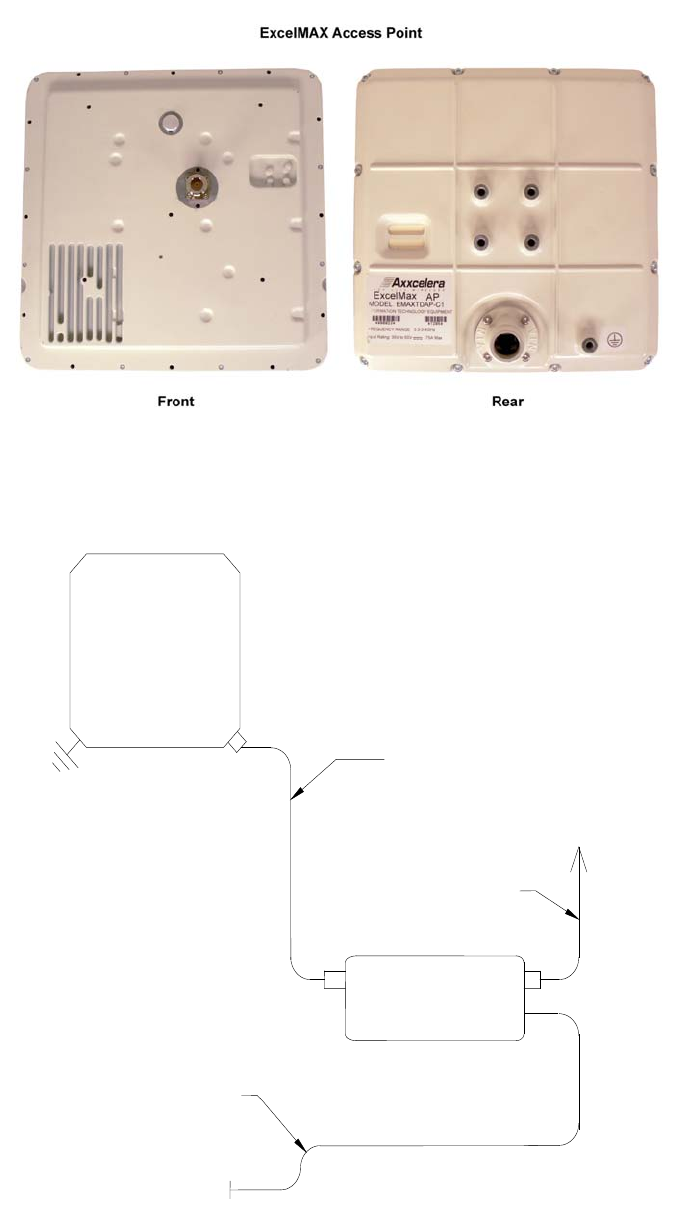
The Access Point is composed of five main physical components:
• Access Point – Outdoor Unit
• Network Interface Adaptor/AC or DC Power Adaptor
• Interconnecting Cable (supplied by the service provider)
• AC or DC Power cord (supplied by the service provider, except for some models where the AC
cords are included)
• Mounting hardware
Additionally, some ExcelMAX Access Point units contain GPS circuitry that connects to a separate
external antenna (supplied by Axxcelera).
Figure 2-1: ExcelMAX Access Point kit
EXCELMAX ACCESS POINT CELL INSTALLATION AND MAINTENANCE GUIDE VERSION 1.4
11 OF 65
.
Figure 2-2: ExcelMAX Access Point views
Figure 2-3: Access Point block diagram
UV-rated, shielded Cat-5 cable
[Ø
.205-.190 in.]
Ø
5.2-4.8 mm
(not supplied)
RJ-45 to RJ-45
Ethernet Cable
(not supplied)
To Computer
Access
Point
AC or DC power connection - as appropriate
AC or DC NIA
EXCELMAX ACCESS POINT CELL INSTALLATION AND MAINTENANCE GUIDE VERSION 1.4
12 OF 65
2.2.1.1 OPTIONAL: GPS Synchronization
Global Positioning System (GPS) support is a factory-fit option for ExcelMAX Access Points.
When supported, a GPS antenna may be connected to each co-located ExcelMAX Access Point
to allow them to synchronize their RF transmissions. Although not required for basic system
operation, use of the “network synchronization” feature synchronizes Access Points so that they
transmit and receive at the same time to limit interference. This function of the GPS reduces
adjacent channel interference, and also reduces interference between adjacent base-station sites
(i.e., frequency re-use).
2.3 Major Components
2.3.1 Indoor Equipment
The indoor equipment consists of the NIA/Power Adapter, which may be an AC or DC variant,
according to the model ordered.
2.3.1.1 AC NIA/Power Adapter
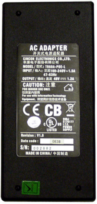
The AC NIA/Power Adapter (Figure 2-4:) is the customer's interface with the Access Point. The AC
NIA/Power Adapter contains interfaces to the AC power supply, customer's data network, and the
Access Point connecting cable. The AC NIA/Power Adapter has a power indicator LED that
illuminates when power is applied to the AC NIA/Power Adapter. The AC NIA/Power Adapter is
wall-mountable using the screw hangers on the back. An included tie wrap is used for strain relief
of the interconnecting cable.
Figure 2-4: AC NIA/Power Adapter
EXCELMAX ACCESS POINT CELL INSTALLATION AND MAINTENANCE GUIDE VERSION 1.4
13 OF 65
2.3.1.2 DC NIA/Power Adapter
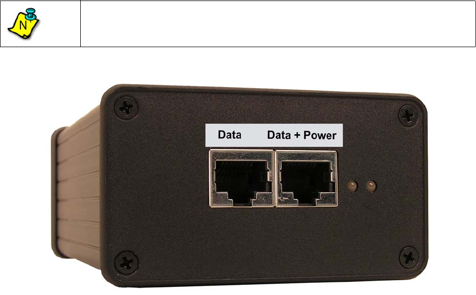
The DC NIA/Power Adapter (Figure 2-5:) is the customer's interface with the Access Point. The
DC NIA/Power Adapter contains interfaces to the DC power supply, customer's data network, and
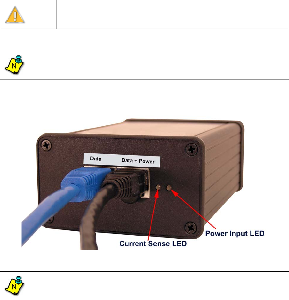
the Access Point connecting cable. The DC NIA/Power Adapter has two LEDs:
1) Power Input LED (furthest from the Access Point RJ45) – The Power Input LED lights green
when the battery input (-ve supply and return) are wired correctly. It does not check the
ground. The Power Input LED lights red if the battery input is reversed (i.e., the -ve supply and
return are connected in reverse order).
2) Current Draw LED – The Current Draw LED is either green or unlit. It lights green when the
Access Point is drawing a significant current (approximately 0.2A or more).
Figure 2-5: DC NIA/Power Adapter
Note
The early DC NIA/Power Adapter units are desk mountable, but future units will be
wall-mountable with four fixing screws provided by the customer.
N
EXCELMAX ACCESS POINT CELL INSTALLATION AND MAINTENANCE GUIDE VERSION 1.4
14 OF 65
2.3.2 Interconnecting cable
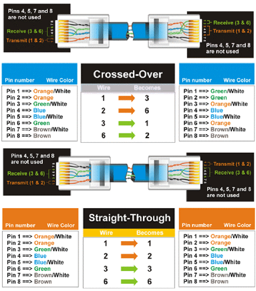
The interconnecting cable is used to connect the Access Point to the NIA. The cable must be
straight-through CAT-5, electrically shielded, and outdoor rated. The cable carries Ethernet data as
well as DC power from the NIA to the Access Point. Customer equipment requiring Ethernet
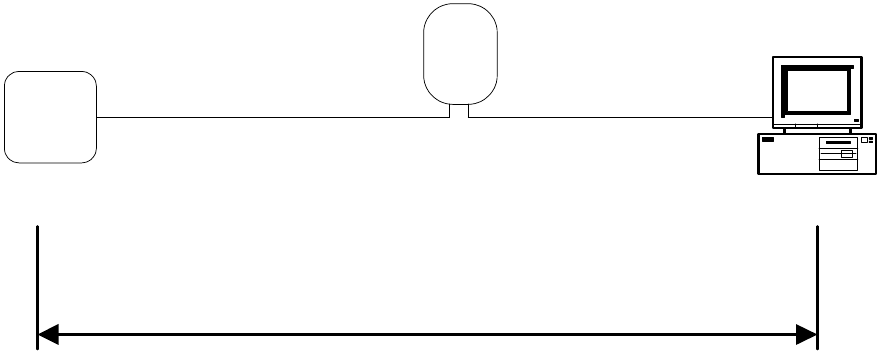
connectivity may be located up to 100 meters from the outdoor Access Point. The cable must have
shielded field-installable connectors on both the Access Point and NIA ends. Wiring distances are
illustrated in Figure 2-6:.
The Access Point supports MDIX, therefore either a straight cable or a cross-over cable can be
used to connect the NIA and any customer equipment.
Figure 2-6: Wiring Distances
NIA
Computer
100 m max.
Ethernet connectivity
Straight-Through CAT-5
Straight-Through CAT-5
or
Crossed-Over CAT-5
Access
Point
EXCELMAX ACCESS POINT CELL INSTALLATION AND MAINTENANCE GUIDE VERSION 1.4
16 OF 65
3.0 Installation
3.1 Compliance Alert – Operation in the 3.4 - 3.6 GHz Band
The CE Marking with alert symbol (see below) appears on the Access Point assembly. The alert
symbol indicates operation on frequency bands that are not harmonized throughout the European
community.
Figure 3-8: Compliance Alert Label
Member states must be notified, in accordance with Article 6.4 of the R&TTE Directive 99/5/EC,
before this equipment can be sold or put into service. Contact Axxcelera Customer Support for an
up-to-date listing of Member State Notifications. See “Technical Support” on page 8.
3.2 Operation in the 3.650 - 3.675 GHz Band
3.2.1 FCC Information to Users @ FCC 15.21 & 15.105
For Class B Unintentional Radiators:
This equipment has been tested and found to comply with the limits for a Class B digital devices,
pursuant to Part 15 of the FCC Rules. These limits are designed to provide reasonable protection
against harmful interference in a residential installation. This equipment generates, uses, and can
radiate radio frequency energy and, if not installed and used in accordance with the instruction
manual, may cause harmful interference to radio communications. However, there is no guarantee
that interference will not occur in a particular installation. If this equipment does cause harmful
interference to radio or television reception, which can be determined by turning the equipment off
and on, the user is encouraged to try to correct the interference by one of more of the following
measures:
• Reorient or relocate the receiving antenna
• Increase the separation between the equipment and receiver
• Connect the equipment into an outlet on a circuit different from that to which the receiver is
connected.
• Consult the dealer or an experienced radio/TV technician for help.
3.2.2 Warning to Users @ FCC 15.21 & 15.105:
Note
This equipment operates in the 3.4 - 3.6 GHz frequency band, which is not
harmonized throughout the community.
Warning
Changes or modifications not expressly approved by Axxcelera Broadband
Wireless could void the user’s authority to operate the equipment
N
EXCELMAX ACCESS POINT CELL INSTALLATION AND MAINTENANCE GUIDE VERSION 1.4
17 OF 65
3.2.3 FCC Label @ FCC 15.19
For Class B - Unintentional Radiators:
This device complies with Part 15 of the FCC Rules. Operation is subject to the following two
conditions: (1) this device may not cause harmful interference and (2) this device must accept any
interference received, including interference that may cause undesired operation.
3.2.4 RF EXPOSURE REQUIRMENTS @ 1.1310 & 2.1091
3.3 Installation Warnings
Please pay attention to the following warnings:
When servicing equipment and selecting a location for the ExcelMAX antennas, it is important to
note that a minimum distance of 25 cm is required between personnel and ExcelMAX antennas to
comply with a radio-frequency exposure limit of 1.0mW/cm2.
Figure 3-9: RF Warning Label
Arcing may occur when connecting the outdoor Ethernet cable to either the Access Point or the
NIA should the power be connected to the NIA. Arcing may irrevocably damage the NIA or the
Access Point. To prevent any chance of damage from occurring, verify that the power is
disconnected from the NIA before attempting to connect the interconnecting cable to either the
Access Point or NIA.
3.4 Environmental Cautions
• Ambient Temperature – The BTS equipment (indoor equipment) must be installed in a
temperature-controlled environment. Ambient temperature should be within a temperature
range of -5 C to +40 C. The TMAs and antennas are outdoor equipment that are designed to
operate over a temperature range of -33 C to +55 C.
• Reliable Grounding – Reliable grounding of the equipment should be maintained. Particular
attention should be given to supply connections other than direct connections to the branch
circuit (e.g. use of power strips).
Warning
To satisfy FCC RF exposure requirements for transmitting devices, a separation
distance of 25 cm or more should be maintained between the antenna of this
device and persons during device operation. To ensure compliance, operations at
closer than this distance is not recommended.
The antenna used for this transmitter must not be co-located in conjunction with
any other antenna or transmitter
°
°
°
°
EXCELMAX ACCESS POINT CELL INSTALLATION AND MAINTENANCE GUIDE VERSION 1.4
18 OF 65
3.5 Installing Outdoor Equipment
3.5.1 Access Point Packing List
See “ExcelMAX Access Point Packing List” on page 9.
3.5.2 Sector Antenna Packing List
The following is included in the shipment of each sector antenna:
• 1 antenna
• 1 upper bracket
• 1 lower bracket
• 2 swing arms
• 2 clamps
• 4 M8X100 Hex Head bolts
• 6 M8X25 Hex Head bolts
• 10 M8 Flat washers
• 10 M8 Lock washers
3.5.3 Omnidirectional Antenna Packing List
• 1 Omni antenna
• 1 Omni antenna pole bracket
• 4 Worm drive clamps
• 2 M3 X 10MM socket head screws
• 2 M3 Lock washers
• 2 M3 Flat washers
3.5.4 Customer Supplied Equipment Required for Antenna Installation
The following is not supplied with the Access Point but is required for installation:
• Installation Collar Kit Axxcelera P/N 020-16300-0003, includes:
• 1 collar clamp
• 1 collar bracket with pin
• 2 nuts
• Box/open end wrench for M8
• Torque wrench (rated to 34 Nm [25 ft.-lb.])
• Ground Lug Ring Terminal Panduit LCB8-14-L or equivalent
3.5.5 Antenna Site Requirements
Basic installation locations should have been established at the initial site survey phase, before
equipment has been delivered.
1) Verify that the elevation of the antennas can be sufficiently high to avoid obstructions and the
antennas will have a clear line of sight to the desired coverage area.

EXCELMAX ACCESS POINT CELL INSTALLATION AND MAINTENANCE GUIDE VERSION 1.4
19 OF 65
2) Be sure to observe local building and electrical codes when running all cables.
3) Verify that the antenna mounting is approved by both the owners of the structure and a
qualified engineer.
4) Verify that the tower mounting base can handle both the weight and the wind loading stress of
the installed antennas and cables.
5) Find suitable equipment locations with consideration for RF cable length restrictions.
3.5.6 Required Tools for Outdoor Installation
Be sure you have the following equipment available for mounting the antennas and Access Point:
Recommended Tool Kit (screw drivers, all-purpose knife, adjustable wrenches, SAE and Metric
socket set and ratchet, hacksaw, wire cutters, wire strippers, coax cable strippers)
• Crimp tool for #8 AWG Ground Lug Terminal, Panduit part number CT-17000 or equivalent
• Electric drill and assorted drill bits
• Extension cord
• UV-rated coax seal, for example, 3M Scotch Seal Industrial Sealant 800
• UV-rated rubberized tape, 3M Weatherban Sealant Tape PF-5422 or similar
• Safety rope and climbing harness
• UV-rated tie wraps
• Antenna sighting equipment
3.5.7 Preparing to Mount the Antenna Brackets
Depending on the type of tower or other style of mounting in use at each site, 5cm (2 in.) diameter
mounting poles will need to be positioned on the tower with the antennas pointed in the proper
direction.
Warning
Do not leave tools lying around unattended on tower platforms and roofs. They
may cause a tripping hazard leading to equipment damage, personal injury or
death.
EXCELMAX ACCESS POINT CELL INSTALLATION AND MAINTENANCE GUIDE VERSION 1.4
20 OF 65
3.6 Installing an Optional Sector Antenna
3.6.1 Grounding the Antenna Mounting
1) Attach the ground lug using the Hex bolt, lock washer and flat washer that came with the
Access Point.
2) Ensure the cable has a good connection. Remove all paint and corrosion where the clamp is
attached.
3) Use dielectric grease on the clamp connection to prevent any electrolysis activity due to
dissimilar metals.
EXCELMAX ACCESS POINT CELL INSTALLATION AND MAINTENANCE GUIDE VERSION 1.4
21 OF 65
3.6.2 Attaching the Sector Antenna to the Mounting Points
1) Observing the correct polarity for the antenna in accordance with the initial RF Site Survey, lay
out the antenna assembly for mounting. Confirm the required polarity against the polarity label
on the back of each antenna assembly.
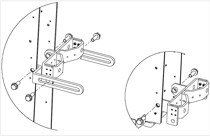
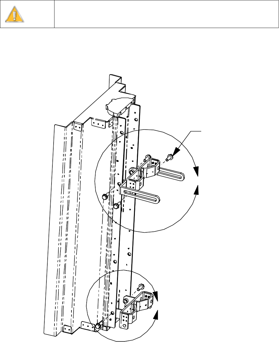
2) Attach the upper and lower brackets to the antenna. See details A and B.
Figure 3-1: Attach upper and lower brackets
Warning
Do not work on antenna installations of any kind when there is any possibility of
electrical storm activity in the area.
A
B
6X M8 Bolts
and Washers
EXCELMAX ACCESS POINT CELL INSTALLATION AND MAINTENANCE GUIDE VERSION 1.4
23 OF 65
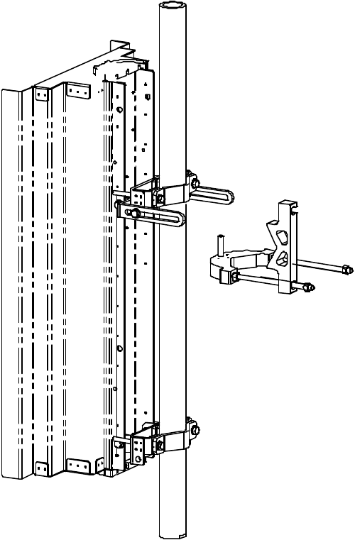
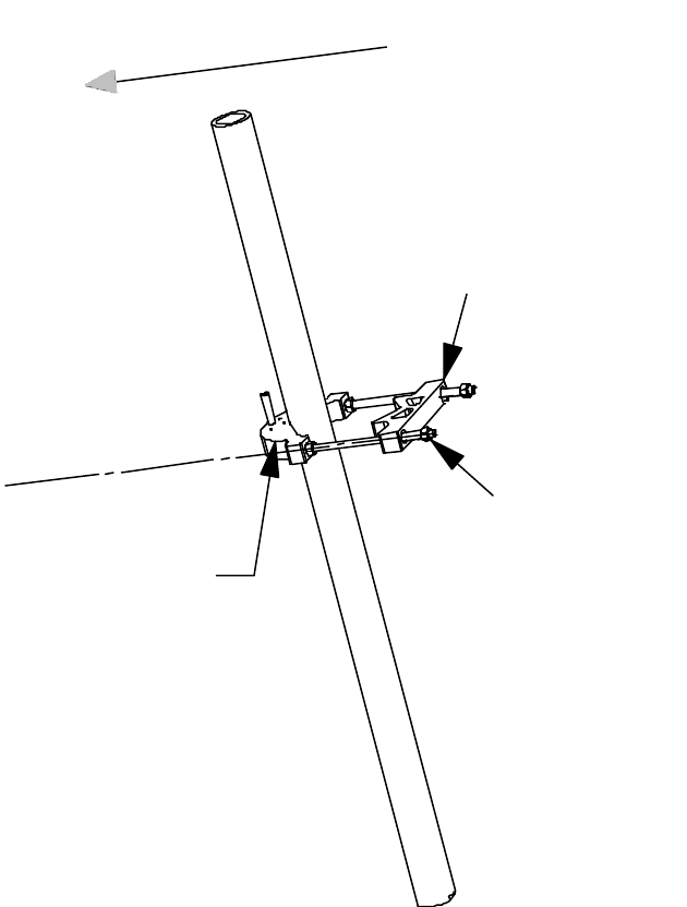
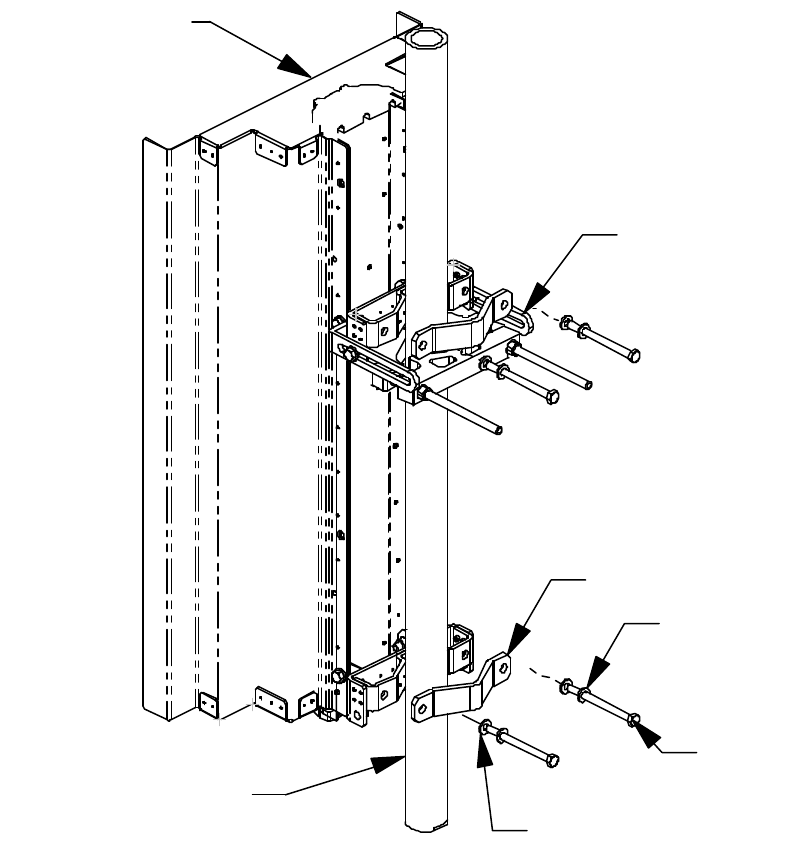
3) Attach the collar bracket to the pole.
Figure 3-3: Attach the collar bracket to the pole.
2X 3/8-16 Hex Nuts
Torque to 24 Nm (17.7 ft-lb)
Installation Collar Bracket
(Included with Installation Collar Kit)
Align Collar Clamp to
the Desired Antenna
Azimuth Pointing Direction
Collar Clamp
EXCELMAX ACCESS POINT CELL INSTALLATION AND MAINTENANCE GUIDE VERSION 1.4
24 OF 65
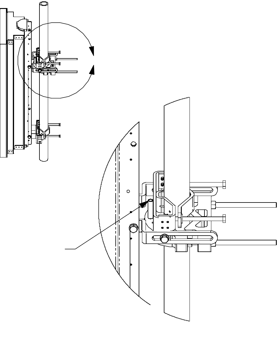
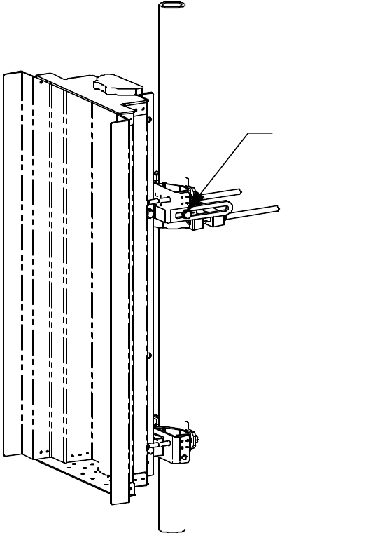
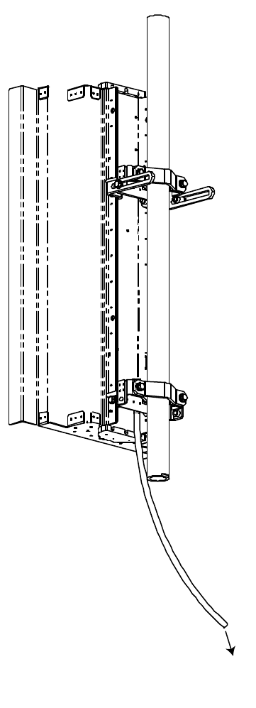
4) Mount the antenna to the pole. Rest the antenna on the Installation Collar Clamp and attach
the clamps loosely. See Detail C.
Figure 3-4: Mount the antenna to the pole.
Antenna with Upper
and Lower Brackets
4X M8X100
2X Clamps
Allowable Pole Outside
Diameter Range
48mm to 114mm
4X Lock Washer
4X Flat Washer
2X Swing Arm
EXCELMAX ACCESS POINT CELL INSTALLATION AND MAINTENANCE GUIDE VERSION 1.4
29 OF 65
8) Attach the cable. Torque the N-connector to 1.0 Nm (8.9 in-lb.).
Figure 3-9: Attach the cable to the antenna
3.6.3 Attaching RF Cable to Access Point
1) Attach the RF cable to the Access Point.
2) Torque the connector to 1.7 Nm (15 in.-lb.).
3) Seal the connection.
Access
Point
EXCELMAX ACCESS POINT CELL INSTALLATION AND MAINTENANCE GUIDE VERSION 1.4
30 OF 65
3.6.4 Grounding the Cables
Ground the RF cables in accordance with the manufacturer’s specification. Ground the cables at
the top of the tower.
Grounding methods may vary from site to site and with the manufacturer’s recommendations.
One method of grounding is to strip the cover from the low-loss cable and clamp a ground strap to
the exposed copper shield.
The strap is then connected to the tower. The clamp is wound with waterproof tape.
3.6.5 Waterproofing Cable Connections
Wrap RF cable connections with waterproof tape.
EXCELMAX ACCESS POINT CELL INSTALLATION AND MAINTENANCE GUIDE VERSION 1.4
31 OF 65
3.7 Installing Optional Omnidirectional Antenna
3.7.1 Grounding the Antenna Mounting
1) Attach the ground lug using the Hex bolt, lock washer and flat washer that came with the
Access Point.
2) Ensure the cable has a good connection. Remove all paint and corrosion where the clamp is
attached.
3) Use dielectric grease on the clamp connection to prevent any electrolysis activity due to
dissimilar metals.
3.7.2 Installing the Omnidirectional Antenna
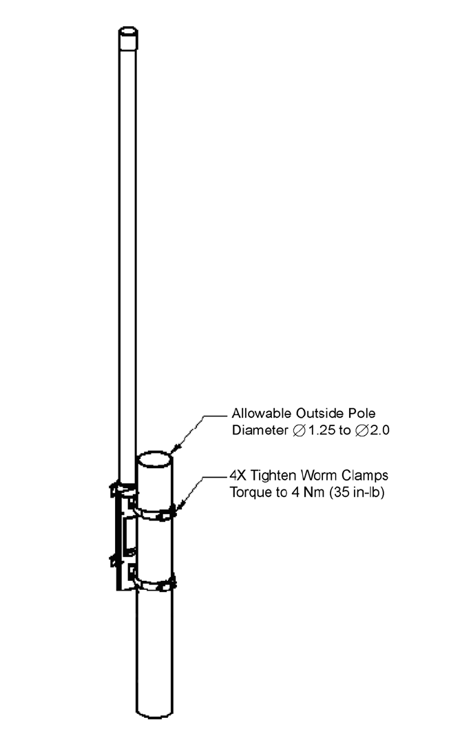
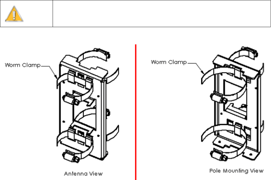
1) Attach the worm clamps to the omni bracket.
Figure 3-10: Attach worm clamps to Omni bracket
Warning
Do not work on antenna installations of any kind when there is any possibility of
electrical storm activity in the area.
EXCELMAX ACCESS POINT CELL INSTALLATION AND MAINTENANCE GUIDE VERSION 1.4
33 OF 65
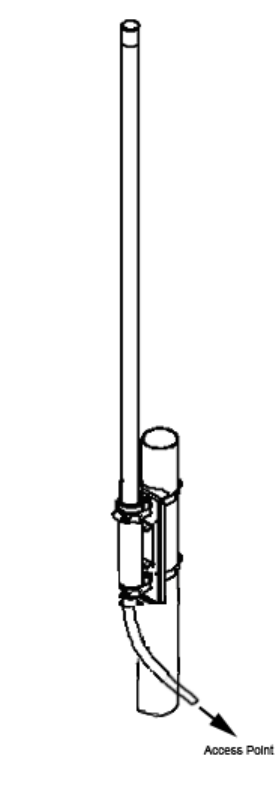
3) Attach the RF cable. Torque the connector to 1.7 Nm (15 in.-lb.).
Figure 3-12: Attach cable to Access Point
3.7.3 Attaching RF Cable to Access Point
1) Attach the RF cable to the Access Point.
2) Torque the connector to 1.7 Nm (15 in.-lb.).
3) Seal the connection.
3.7.4 Grounding the Cables
Ground the RF cables in accordance with the manufacturer’s specification. Ground the cables at
the top of the tower.
Grounding methods may vary from site to site and with the manufacturer’s recommendations.
One method of grounding is to strip the cover from the low-loss cable and clamp a ground strap to
the exposed copper shield.
EXCELMAX ACCESS POINT CELL INSTALLATION AND MAINTENANCE GUIDE VERSION 1.4
34 OF 65
The strap is then connected to the tower. The clamp is wound with waterproof tape.
3.7.5 Waterproofing Cable Connections
Wrap RF cable connections with waterproof tape.
3.8 Installing the Access Point
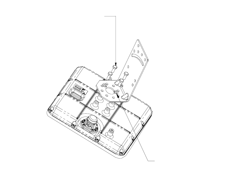
3.8.1 Mounting L-bracket to the Access Point
Figure 3-13: Mounting the L-bracket to the Access Point
1) Attach the L-bracket to the Access Point using 4 hex bolts with 4 split lock washers.
2) Torque the hex bolts to 8.81 ±67 Nm (78 ±6 in.-lb.) with a 10 mm open-end wrench.
M6 X 16 mm Hex Bolt
4 ea
M6 Split Lock Washer
4 ea
EXCELMAX ACCESS POINT CELL INSTALLATION AND MAINTENANCE GUIDE VERSION 1.4
35 OF 65
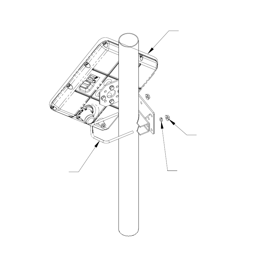
3.8.2 Mounting Access Point to the Pole
Figure 3-14: Mounting the Access Point to the Pole
Attach the Access Point to the pole using the clamp, U-bolt, M6 split lock washer and M6 serrated
flange nut. Hex nuts should be tightened enough to prevent the Access Point from falling.
U-Bolt
M6 Serrated
Flange Nut
2 ea
M6 Split
Lock Washer
2 ea
Access Point
EXCELMAX ACCESS POINT CELL INSTALLATION AND MAINTENANCE GUIDE VERSION 1.4
36 OF 65
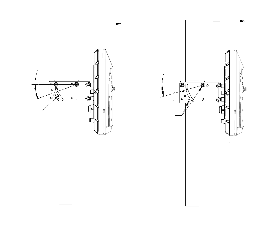
3.8.3 Aligning the Access Point
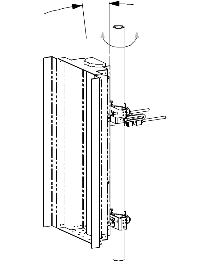
Figure 3-15: Aligning the Access Point
1) Rotate the Access Point to the desired azimuth pointing direction.
2) Tilt the Access Point to adjust the elevation (L-bracket may need to be rotated 180° for further
adjustment).
3) Torque the U-bolt nuts to 8.8 ±7 Nm (78 ±6 in.-lb.).
(OPTIONAL FIXED
ELEVATION MOUNTING)
Azimuth direction
16° Increments
Fixed elevation
holes
ADJUSTABLE ELEVATION MOUNTING
Azimuth direction
Elevation
adjustment
slot
20° Max.
EXCELMAX ACCESS POINT CELL INSTALLATION AND MAINTENANCE GUIDE VERSION 1.4
37 OF 65
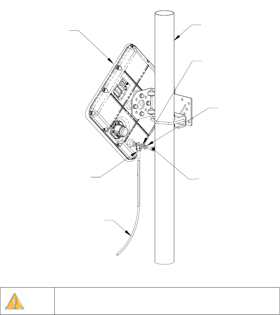
3.8.4 Attaching the Ground Wire (recommended)
Figure 3-16: Attaching the Ground Wire
1) Crimp one end of ∅ 2.8 mm (8 AWG) wire to the ground lug.
2) Attach the assembled ground lug to the transceiver housing using an M6 x 16 lg hex bolt, M6
split lock washer and M6 flat washer. Torque the hex bolt to 8.8 ± .7 Nm (78 ± 6 in.-lb.) using a
10 mm open-end wrench.
3) Attach the remaining ground wire end to the "Earth Ground" and/or mounting pole per the local
electrical code.
Warning
Axxcelera recommends grounding the unit and supplies the following instructions
as a reference only. Necessary grounding should be completed per local electrical
codes.
M6 Hex Bolt
Mounting Pole
M6 Lock Washer
M6 Flat Washer
8 AWG )
Ø2.8 mm(
Ground Wire (not provided)
To Earth Ground
Access Point
Ground Lug
EXCELMAX ACCESS POINT CELL INSTALLATION AND MAINTENANCE GUIDE VERSION 1.4
38 OF 65
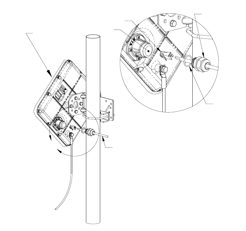
3.8.5 Attaching the Cat-5 Cable
Figure 3-17: Attaching the Cat-5 Cable
1) Push the un-terminated, un-stripped (no plug) Cat-5 cable through the hole in the gland seal.
Loosen the nut on top of the gland seal if the wire is not moving freely.
2) Using a shielded RJ-45 plug, terminate (attach plug) to the Cat-5 cable per the manufacturer's
recommended specifications for plug attachment. (Recommended manufacturer: AMP, P/N 5-
569552 or equivalent)
3) Remove and discard the cap plugging the hole in the transceiver.
4) Slide the O-ring over the Cat-5 cable and onto the PG-11 gland seal.
5) Look into the open hole and orient the RJ-45 plug, pushing the plug into the socket until the
connectors are locked together.
6) Thread the gland seal into the transceiver and torque using the bottom nut of the gland seal
(closest to the Access Point) to 3.8 Nm (33.2 in.-lb.) using the 7/8 open-end wrench.
Cap
Shielded RJ-45 Plug
(not provided)
Access Point
UV-resistant, shielded, outdoor Cat-5 Cable
O-ring
PG-11 Gland
Seal
DETAIL A
SCALE 1 : 2
A
(Ø5.2-4.8 mm [Ø.205-.190 in] to IDU (not provided)
EXCELMAX ACCESS POINT CELL INSTALLATION AND MAINTENANCE GUIDE VERSION 1.4
40 OF 65
3.9 Power and Data Connections – AC and DC Power Options
There are two types of PSU/NIA units:
1) AC PSU/NIA
2) DC PSU/NIA
The installation instructions for the AC and DC units are different. For instructions on installing the
AC PSU/NIA, refer to 3.9.1. For instructions on installing the DC PSU/NIA, refer to 3.9.2.
ExcelMAX Access Points are shipped with either the AC PSU/NIA or the DC PSU/NIA unit,
depending on what the customer ordered.
EXCELMAX ACCESS POINT CELL INSTALLATION AND MAINTENANCE GUIDE VERSION 1.4
41 OF 65
3.9.1 AC PSU/NIA Option
3.9.1.1 Connecting the Access Point to the AC Power Supply/NIA
The following procedures will guide you through the connection of the AC PSU/NIA unit:
1) Remove the new AC PSU/NIA from the installation kit.
2) Using a shielded RJ-45 plug, terminate (attach plug) to the Access Point Cat-5 cable per the
manufacturer's recommended specifications for plug attachment. (Recommended
manufacturer: AMP P/N 5-569552).
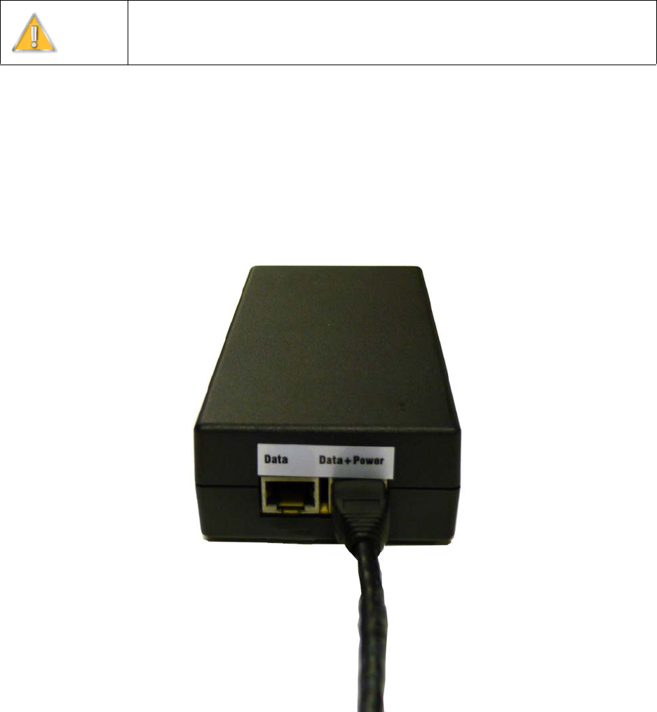
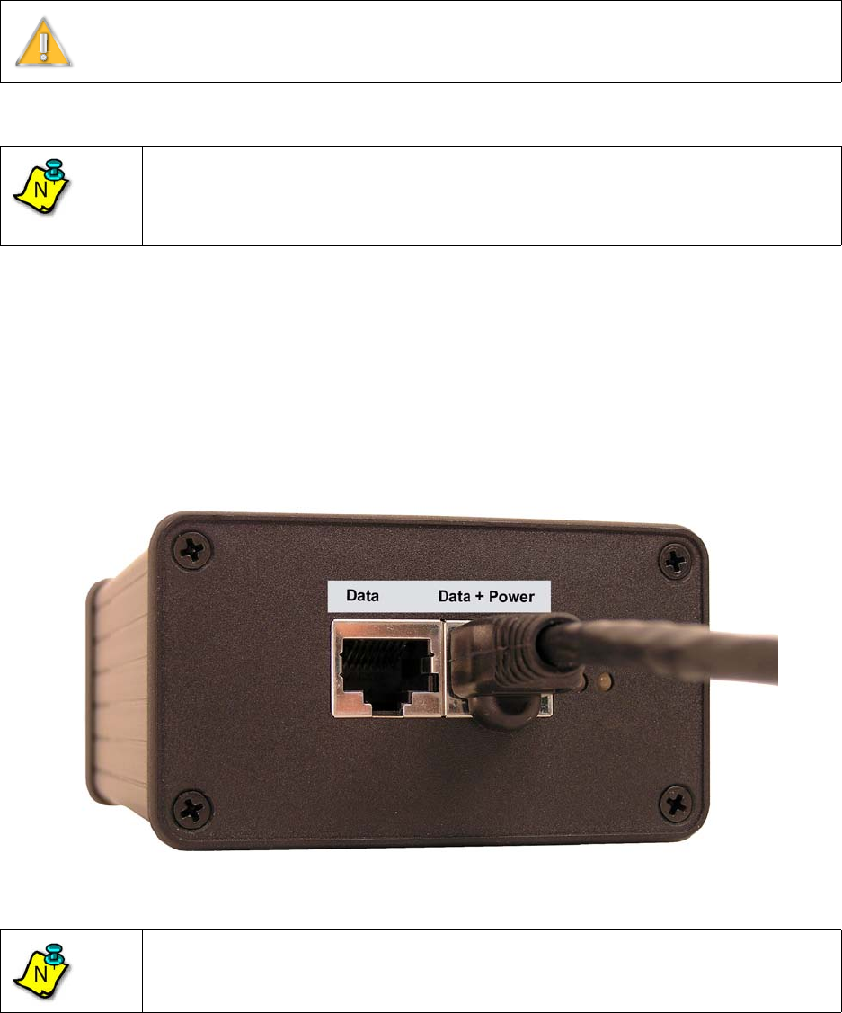
3) Insert the RJ-45 plug from the outdoor Access Point into the RJ-45 receptacle, labeled
Data+Power, on the NIA (Figure 3-18:).
Figure 3-18: Connect the Access Point
Warning
It is extremely important to connect the AC power to the AC PSU/NIA as the last
step. Connecting AC power prematurely can damage the Access Point and lead to
faulty behavior.
EXCELMAX ACCESS POINT CELL INSTALLATION AND MAINTENANCE GUIDE VERSION 1.4
42 OF 65
3.9.1.2 Completing the Connection of the AC Power Supply/NIA
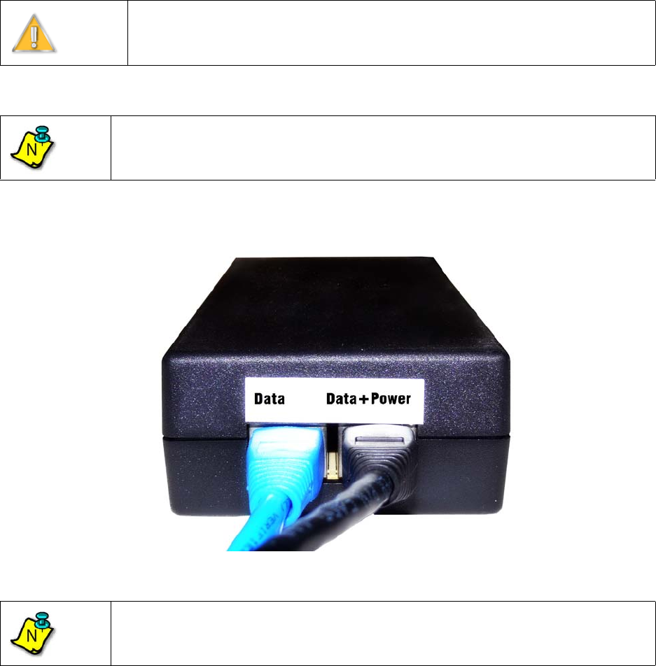
1) Insert one end of an RJ-45 to RJ-45 Ethernet cable assembly to the RJ-45 receptacle, labeled
Data, on the outside of the NIA and the other end to the customer's computer (Figure 3-19:).
Figure 3-19: Connect customer computer or network device
2) Check to see that the connection to the Access Point is in place.
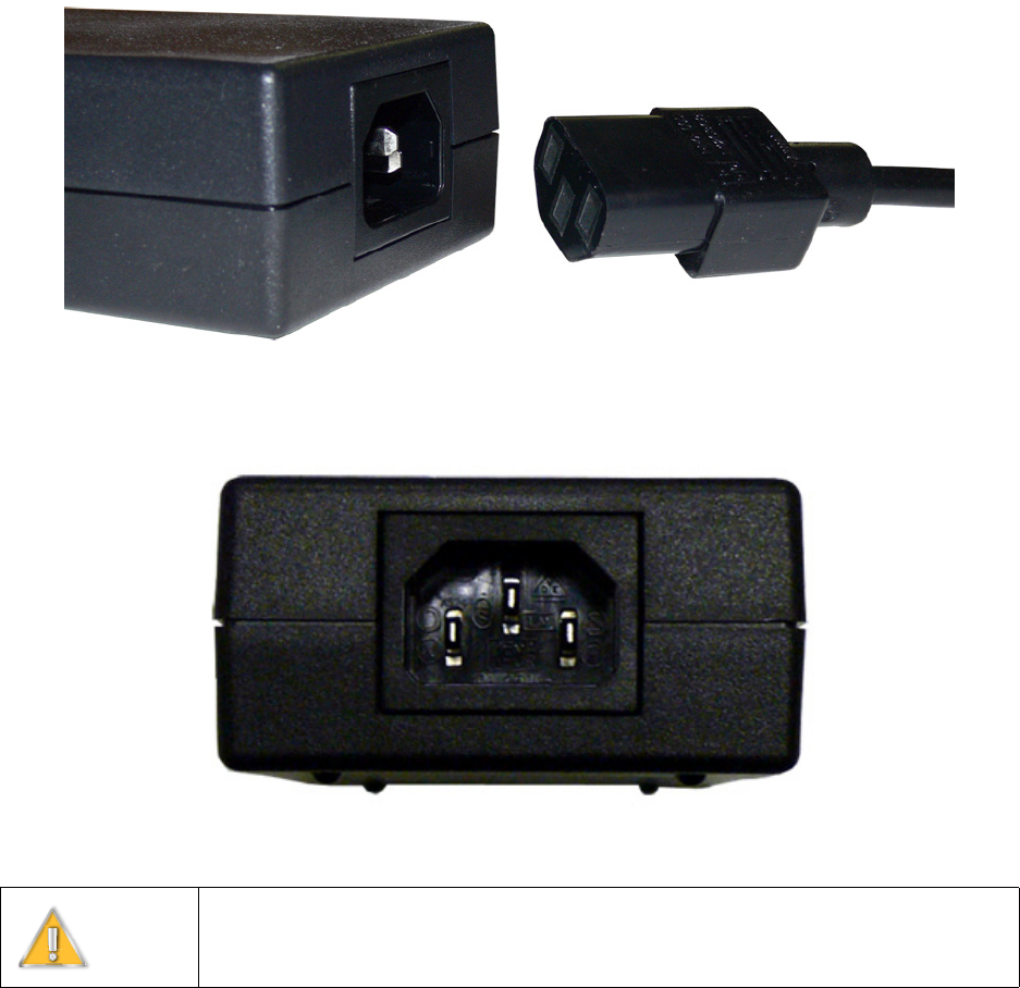
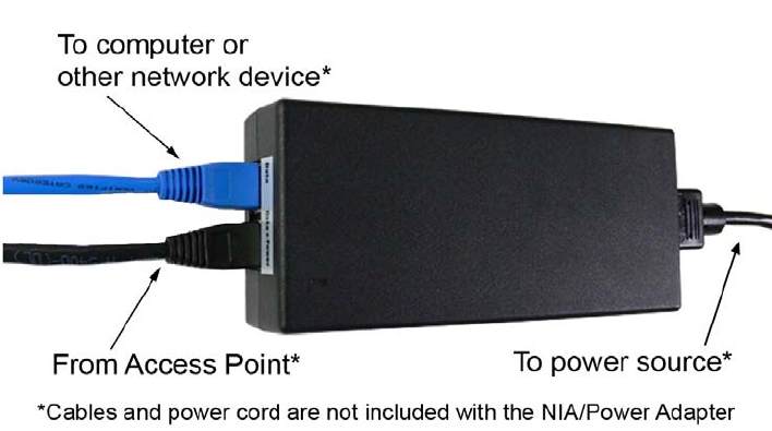
3) Connect the three-prong female power cord to the NIA. The power cord uses an IEC-320-C13
type connector (Figure 3-20: and Figure 3-21:).
Warning
It is extremely important to connect the AC power to the AC PSU/NIA as the last
step. Connecting AC power prematurely can damage the Access Point and lead to
faulty behavior.
Note
Other than the models where the power supply cord is included, the AC PSU/NIA
does not come with cables or power cord. Service provider must provide their own
cables and power cord.
Note
Customer equipment requiring Ethernet connectivity may not be located more than
100 m (328 ft.) from the Access Point.
N
N
EXCELMAX ACCESS POINT CELL INSTALLATION AND MAINTENANCE GUIDE VERSION 1.4
43 OF 65
4) Insert the power cord connector from the NIA into the nearest wall outlet.
Figure 3-20: Connect the power cord
Figure 3-21: NIA’s IEC320-C7 type connector
Warning
It is extremely important to connect the AC power to the NIA as the last step.
Connecting AC power prematurely can damage the Access Point and lead to faulty
behavior.
EXCELMAX ACCESS POINT CELL INSTALLATION AND MAINTENANCE GUIDE VERSION 1.4
44 OF 65
5) The completed setup is shown in Figure 3-22:. After verifying all connections to the NIA,
connect the power cord to the wall and complete the process of setting up of the Access Point.
Figure 3-22: NIA setup is complete

EXCELMAX ACCESS POINT CELL INSTALLATION AND MAINTENANCE GUIDE VERSION 1.4
45 OF 65
3.9.2 DC PSU/NIA Option
The DC PSU/NIA unit powers the ExcelMax Access Point from a -48V DC power source, typically
a battery back-up supply. The ExcelMax DC PSU/NIA units (020-44109-0802; see Appendix B:)
are black, and output an isolated supply of +53.5V.
The DC PSU/NIA has an input power connector at one end, and is supplied with the mating plug,
which has 3 screw terminals on it for easy installation. The two supply wires and Earth/Ground are
connected here. The Power Input LED is green when the power connection is wired correctly, but
red if the polarity is reversed. It is off when there is no power.
The DC PSU/NIA has two RJ45 connectors at the other end. One is for the LAN Ethernet
connection. The other is a Power-Over-Ethernet type connection, supplying power and data to the
ExcelMAX Access Point. The Current Sense LED is green when the Access Point is on and
drawing minimum specified current (approximately 0.2A or more).
Warning
ExcelMAX Access Points can only be powered by the ExcelMax version of the DC
PSU/NIA. The Access Point will be permanently damaged if used with another
version of the DC PSU/NIA. The DC PSU/NIA unit contains no serviceable parts.
Warning
The DC PSU/NIA unit is designed for indoor use only. The body of the unit is used
as a heat sink, and will get very warm.
EXCELMAX ACCESS POINT CELL INSTALLATION AND MAINTENANCE GUIDE VERSION 1.4
46 OF 65
3.9.2.1 Connecting the Access Point to the DC Power Supply/NIA
The following procedures will guide you through the connection of the DC PSU/NIA unit:
1) Remove the new DC PSU/NIA from the installation kit.
2) Using a shielded RJ-45 plug, terminate (attach plug) to the Access Point Cat-5 cable per the
manufacturer's recommended specifications for plug attachment. (Recommended
manufacturer: AMP P/N 5-569552).
3) Insert the RJ-45 plug from the outdoor Access Point into the RJ-45 receptacle, labeled
Data+Power, on the DC PSU/NIA (Figure 3-23:).
Figure 3-23: Connect the Access Point
Warning
It is extremely important to connect the DC power to the DC PSU/NIA as the last
step. Connecting DC power prematurely can damage the Access Point and lead to
faulty behavior. The DC PSU/NIA unit contains no serviceable parts.
Note
The power should be tested - the power (outer) LED should light green. If the light is
red or off then the connections are incorrect.
The Earth connection is not checked by the LED.
Note
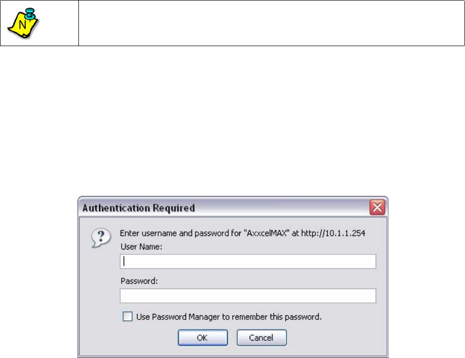
The DC PSU/NIA does not come with cables or power cord. Service provider must
provide their own cables and power supply wires.
N
N
EXCELMAX ACCESS POINT CELL INSTALLATION AND MAINTENANCE GUIDE VERSION 1.4
47 OF 65
3.9.2.2 Completing the Connection of the DC Power Supply/NIA
1) Insert one end of an RJ-45 to RJ-45 Ethernet cable assembly to the RJ-45 receptacle, labeled
Data, on the outside of the DC PSU/NIA and the other end to the customer's computer (Figure
3-24:).
Figure 3-24: Connect customer computer or network device
2) Check to see that the connection to the Access Point is in place.
Warning
It is extremely important to connect the DC power to the DC PSU/NIA as the last
step. Connecting DC power prematurely can damage the Access Point and lead to
faulty behavior.
Note
The DC PSU/NIA does not come with cables or power cord. Service provider must
provide their own cables and power cord.
Note
Customer equipment requiring Ethernet connectivity may not be located more than
100 m (328 ft.) from the Access Point.
N
N
EXCELMAX ACCESS POINT CELL INSTALLATION AND MAINTENANCE GUIDE VERSION 1.4
48 OF 65
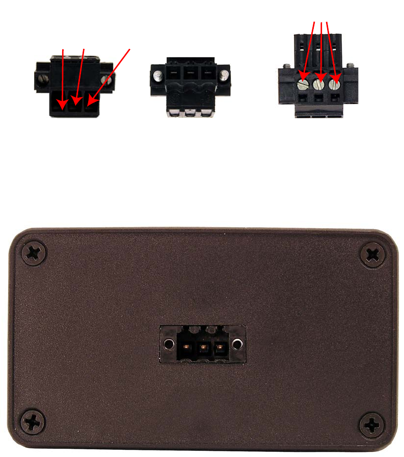
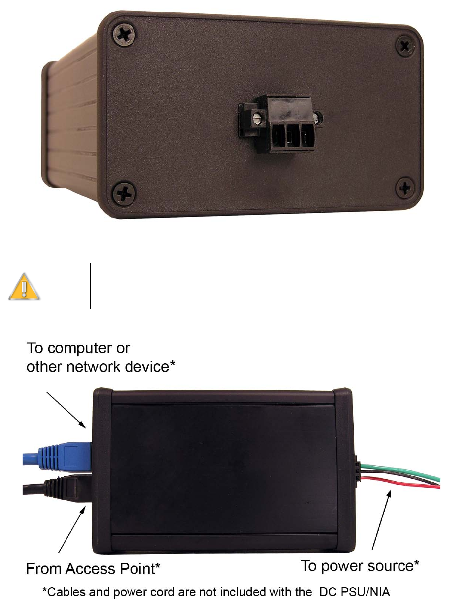
3) Screw three wires (22-14AWG) from the power supply into the mating plug (-48V DC supply,
DC return, and earth) (Figure 3-25:).
Figure 3-25: Mating Power Plug
4) Connect the assembled mating plug into the DC PSU/NIA (Figure 3-26: and Figure 3-27:).
Figure 3-26: NIA’s connector without mating plug
Exterior View Mating View Top View
Mating Power Plug Connector
-48V DC Supply, DC Return, and Earth Ground
Clamping screws for DC Supply,
DC Return , and Earth Ground wires
EXCELMAX ACCESS POINT CELL INSTALLATION AND MAINTENANCE GUIDE VERSION 1.4
49 OF 65
.
Figure 3-27: Connect the mating plug
5) The completed setup is shown in Figure 3-28:.
Figure 3-28: NIA setup is complete
Warning
It is extremely important to connect the DC power to the DC PSU/NIA as the last
step. Connecting DC power prematurely can damage the Access Point and lead to
faulty behavior.

EXCELMAX ACCESS POINT CELL INSTALLATION AND MAINTENANCE GUIDE VERSION 1.4
50 OF 65
4.0 Configuring an Access Point for Single-Channel Use
Using the Access Point setup screens, follow the procedure below to configure a single-channel
Access Point.
The following topics cover configuring an Access Point for single-channel use.
• Logging into the Access Point Web Page
• Configuring IP Address Settings
• Configuring System Information Settings
• Completing Access Point Setup
Note
Where dynamic frequency selection (DFS) is not required, the Access Point will only
support a single-channel configuration.
N
EXCELMAX ACCESS POINT CELL INSTALLATION AND MAINTENANCE GUIDE VERSION 1.4
51 OF 65
4.1 Logging into the Access Point Web Page
1) If the installer laptop is not running, power on and wait for the installer laptop to complete ini-
tialization to the desktop.
2) Set the IP address to be on the same network as the single-channel Access Point.
3) To run the Access Point setup operation, open an internet browser and type the following
Access Point’s IP address in the browser Address field:
Example: 10.1.1.254
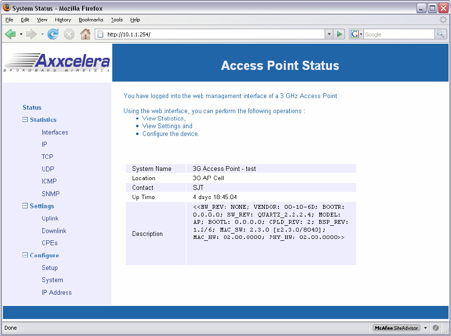
4) When the authentication popup appears (Figure 4-1:), type the following default values in the
user name/password fields:
User Name: admin
Password: admin
Figure 4-1: Authentication popup
Note
The Access Point default IP address is 10.1.1.254, and the netmask is 255.255.255.0.
N
EXCELMAX ACCESS POINT CELL INSTALLATION AND MAINTENANCE GUIDE VERSION 1.4
52 OF 65
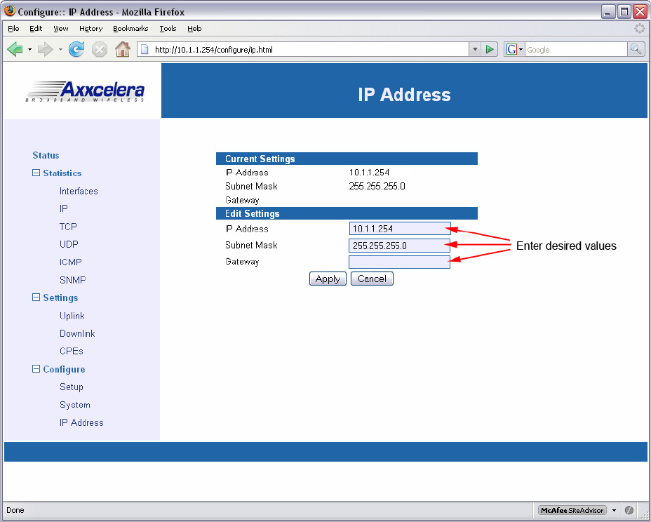
5) When the Access Point Status screen appears (Figure 4-2:), continue with the setup process
by using the links from the screen menu, starting with configuring the IP Address settings.
Figure 4-2: Single-Channel Access Point Status screen
EXCELMAX ACCESS POINT CELL INSTALLATION AND MAINTENANCE GUIDE VERSION 1.4
53 OF 65
4.1.3 Configuring IP Address Settings
Follow this procedure to configure the IP Address settings.
1) Select IP Address from the menu list.
2) When the IP Address screen (Figure 4-3:) appears, in the Edit Settings fields enter the
appropriate IP Address, Subnet Mask, and Gateway addresses.
Figure 4-3: Configuring the IP Address
3) Click Apply to accept the addresses. The Current Settings will display the address values.
4) If the current addresses need to be changed, then enter new addresses in the Edit Settings
fields and click Apply.
EXCELMAX ACCESS POINT CELL INSTALLATION AND MAINTENANCE GUIDE VERSION 1.4
54 OF 65
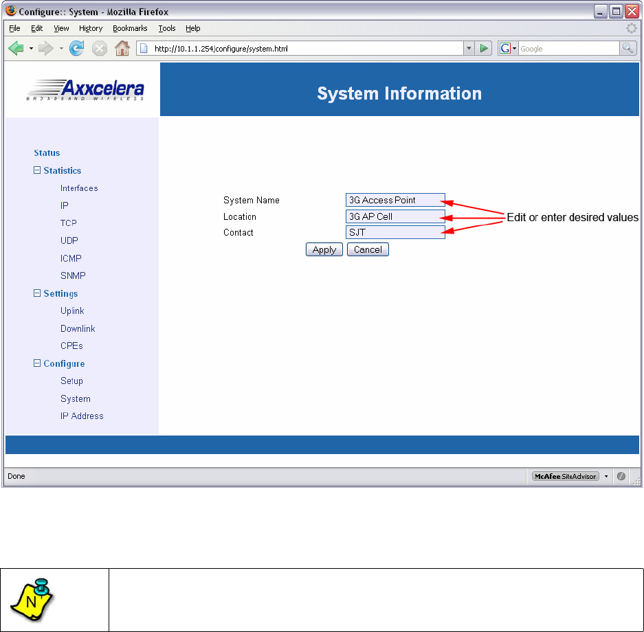
4.1.4 Configuring System Information Settings
Follow this procedure to configure the System Information settings.
1) Select System from the menu list.
2) When the System Information screen (Figure 4-4:) appears, enter the System Name,
Location, and Contact information in the appropriate fields.
Figure 4-4: Configuring System Information Settings
3) Click Apply to accept the entries.
4) If the current information needs to be changed, then enter the new information in the
appropriate fields and click Apply.
Note
Access Points with the same Location name will be placed into the same cell on the
Axxcelera NMS.
N
EXCELMAX ACCESS POINT CELL INSTALLATION AND MAINTENANCE GUIDE VERSION 1.4
55 OF 65
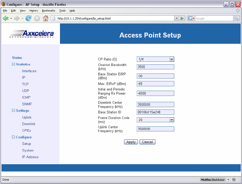
4.1.5 Completing Access Point Setup
Follow this procedure to complete the setup of the Access Point.
1) Select Setup from the menu list.
2) When the Access Point Setup screen appears (Figure 4-5:), enter the desired parameters.
Figure 4-5: Single-Channel Access Point Setup screen
EXCELMAX ACCESS POINT CELL INSTALLATION AND MAINTENANCE GUIDE VERSION 1.4
56 OF 65
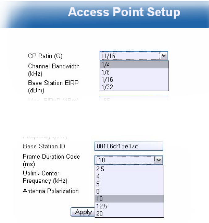
3) Select the desired CP Ratio (G) from the dropdown list (Figure 4-6:).
Figure 4-6: CP Ratio (G) options
4) Select the desired Frame Duration Code from the dropdown list (Figure 4-7:
Figure 4-7: Frame Duration Code options
5) Click Apply to complete the single-channel Access Point setup.

EXCELMAX ACCESS POINT CELL INSTALLATION AND MAINTENANCE GUIDE VERSION 1.4
57 OF 65
4.1.6 Power Settings for Operation in the 3.650 - 3.675 GHz Band
AP Antenna Gain
..........
16.5 dBi External, Sectored, 60deg
1 dBi .......... Cable Loss
Channel Spacing: 7MHz
Freq Gant BW TX set PPSD
(cond)
PPSD
EIRP
PPSD
EIRP Limit
Margin
(MHz) (dBi) (MHz) (dBm) (dBm/MHz) (dBm/MHz) (dBm/MHz) dB
3662.5 15.5 7 10 14.45 29.95 30 0.05
Channel Spacing: 3.5MHz
Freq Gant BW TX set PPSD
(cond)
PPSD
EIRP
PPSD
EIRP Limit
Margin
(MHz) (dBi) (MHz) (dBm) (dBm/MHz) (dBm/MHz) (dBm/MHz) dB
3662.5 15.5 3.5 8 14.49 29.99 30 0.01
AP Antenna Gain 14 dBi External, Sectored, 90deg
1 dBi Cable Loss
Channel Spacing: 7MHz
Freq Gant BW TX set PPSD
(cond)
PPSD
EIRP
PPSD
EIRP Limit
Margin
(MHz) (dBi) (MHz) (dBm) (dBm/MHz) (dBm/MHz) (dBm/MHz) dB
3662.5 13 712 16.95 29.95 30 0.05
Channel Spacing: 3.5MHz
Freq Gant BW TX set PPSD
(cond)
PPSD
EIRP
PPSD
EIRP Limit
Margin
(MHz) (dBi) (MHz) (dBm) (dBm/MHz) (dBm/MHz) (dBm/MHz) dB
3662.5 13 3.5 10 16.97 29.97 30 0.03

EXCELMAX ACCESS POINT CELL INSTALLATION AND MAINTENANCE GUIDE VERSION 1.4
58 OF 65
AP Antenna Gain 10 dBi External, Omni
1 dBi Cable Loss
Channel Spacing: 7MHz
Freq Gant BW TX set PPSD
(cond)
PPSD
EIRP
PPSD
EIRP Limit
Margin
(MHz) (dBi) (MHz) (dBm) (dBm/MHz) (dBm/MHz) (dBm/MHz) dB
3662.5 9 7 16 20.95 29.95 30 0.05
Channel Spacing: 3.5MHz
Freq Gant BW TX set PPSD
(cond)
PPSD
EIRP
PPSD
EIRP Limit
Margin
(MHz) (dBi) (MHz) (dBm) (dBm/MHz) (dBm/MHz) (dBm/MHz) dB
3662.5 93.5 14 20.97 29.97 30 0.03
EXCELMAX ACCESS POINT CELL INSTALLATION AND MAINTENANCE GUIDE VERSION 1.4
59 OF 65
5.0 Maintenance Guide
This section is intended for use by all Field Service Engineers.
Catastrophic failures can often be prevented by a regimen of preventative maintenance. The
following is a list of maintenance suggestions supported by Axxcelera.
1) Perform regular visual inspections. Check the butyl-rubber waterproofing tape used to cover
the cable connectors for integrity.
2) Check areas around ground clamps for any signs of oxidation or corrosion that might
compromise the connection.
3) Periodically check the connectors for tightness.
4) Take care not to compromise the integrity of the cabling. IF, RF and Ethernet cabling can
become damaged if it becomes pinched, for example during site construction or renovation.
5) Periodically check the integrity of the signal path clearance between the Access Point and the
CPE. It may seem obvious, but when service is disrupted, and there is no obvious suspect
hardware, it is possible that something in the environment has changed and the RF path itself
is suspect. The path that was unobstructed yesterday might not be so clear today.
6) Check for near-field objects. No metallic objects, such as telephone or power wires, poles or
fences, should be within the field view of the antenna (+/- 8 degrees) within the first 20 feet.
These objects could reflect the microwave energy back to the antenna and distort the RF
beam. This reflection could also cause the signal to be directed away from where it is needed.
7) Non-metallic objects in the vicinity can absorb microwave energy; however, when they become
wet, these objects can become very reflective. Shots over water or flat surfaces should be
avoided because these surfaces cause reflections that increase multipath. Multipath is when
the same signal is received twice; one signal is the direct path and the other is the reflected
(delayed) signal. The delayed signal can be out of phase with the direct signal and cause
cancellation.
8) Periodically check for ground loops that might be introduced into the system inadvertently by
engineers adding new equipment without regard to the grounding system already in place.
Ground loops can cause noise problems in the system.
EXCELMAX ACCESS POINT CELL INSTALLATION AND MAINTENANCE GUIDE VERSION 1.4
60 OF 65
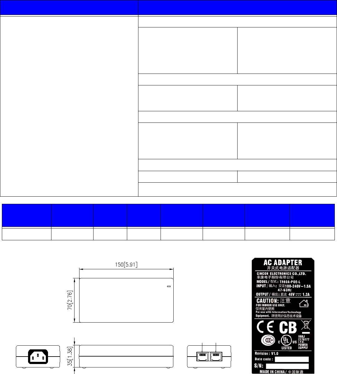
Appendix A: NIA/Power Adapter Specifications: Model # TR60A-POE-L
Features Specifications
• Universal Input: 90 ~ 264Vac
• Continuous Short Circuit Protection
• Conductive EMI Meets CISPR/FCC Class B
• High Efficiency at 75% Minimum
• Lighting Protection
NOTE 1: Voltage accuracy is set at 60% full load.
2: Add a 0.1uF ceramic capacitor and a 10uf
E.L. capacitor to output for Ripple & Noise
measuring @20MHz BW.
3: Line regulation is measured from 100Vac
to 240Vac with full load.
4: Load regulation is measured from 60% to
100% full load and from 60% to 20% full
load(60% +/- 40% full load).
• Input Characteristics
Voltage
Frequency
Inrush Current
Conducted EMI
Isolation
Leakage Current
90 ~ 264Vac
47 to 63Hz
50A Max. @ 264Vac
CISPR/FCC Class B
Input to output = 4,242Vdc
1.5mA max.
• Output Characteristics
Hold-up Time
Short Circuit Protection
Over Voltage Protection
8mS typ. @ 115Vac
Auto-Recovery
Auto-Recovery
• Environmental Characteristics
Operating Temperature
Storage Temperature
Operating Humidity
Cooling
0 ~ 40 C
-50 ~70 C
5% ~ 95%
Free air cooling
• Mechanical Outline
Dimensions 150mm x 70mm x 35mm
Typical at 25 C, nominal line and 75% load, unless otherwise Specified.
Model Output
Voltage Max.
Load Min.
Load Ripple &
Noise Voltage
Accuracy Line
Regulation Load
Regulation
TR60A-POE-L 48 V 1.2 A 0 A 1% +/- 2% +/- 1% +/- 2%
Figure A-1: NIA/Power Adapter Schematic Drawing Figure A-2: NIA/Power Adapter label
°
°
°
2/!UY),*
3/!UY).*
4/!SY),*
5/!ED,
6/!ED,
7/!SY).*
8/!HOE
9/!HOE
6/!OD
8/!OD
9/!OD
7/!SY).*
3/!UY).*
4/!SY),*
5/!OD
2/!UY),*
Ebub!jo Qpxfs,
Ebub!pvu
92 92

EXCELMAX ACCESS POINT CELL INSTALLATION AND MAINTENANCE GUIDE VERSION 1.4
61 OF 65
Appendix B: ExcelMax DC PSU/NIA (020-44109-0802)
Features Specifications
Dimensions Desk-Mounting Unit:
L= 126mm
W= 81mm
H= 46mm
Wall-Mounting Unit:
L= 153mm
W= 81mm
H= 51mm
Weight 350g
Color Black
Operating Temperature 0 C to +40 C ambient (free air cooling)
For Indoor Use Only
Storage Temperature -40 C to +70 C
Input DC, -48V (+/-20%)
Output DC, +53.5V (typical)
Max output current = 0.8A
Max Power = 42W
Efficiency 85% typical
Protection Continuous short-circuit protection on output
Internal fuse on negative supply input
Thermal shutdown at 100C
RoHS compliance Yes
°
°
°
°
EXCELMAX ACCESS POINT CELL INSTALLATION AND MAINTENANCE GUIDE VERSION 1.4
62 OF 65
Appendix C: Glossary of Terms and Abbreviations
Bandwidth A measure (in Hertz) of a transmission facility’s ability to transmit signals that
span a range of frequencies without degrading the amount of power in the
signal. For example, a bandwidth of 2700 Hz.
Base Station The indoor and outdoor equipment located at the central site.
Bit Error Rate
(BER) The percentage of received bits in error compared to the total number of bits
received. Usually expressed as a number to the power of 10. For example, 10
means that one in every 100,000 bits transmitted will be wrong.
Broadband A high number of signals multiplexed onto a single transmission channel.
BTS Base Station Termination System
CPE This unit contains both the antenna and the modem.
Default Gateway A unique IP address that a device uses to put traffic on the network when it
knows the address of a device it is trying to contact, but does not know exactly
where on the network or on which sub-network it is located.
Downstream Traffic traveling from the Access Point to the CPE
Fault A hard failure or performance degradation serious enough to destroy the ability
of a network element to function effectively.
FEC Forward-Error correction
Firmware Software “burned” into a chip.
Frequency The rate at which an electromagnetic waveform, such as an electrical current,
alternates. Measured in Hertz, i.e., cycles per second.
Gain The increase in signaling power that occurs as a signal is boosted by an
electronic device. Measured in decibels (dB).
IP Internet Protocol. Set of standardized rules for the transmission of data over the
internet.
IP Address A unique numerical identifier of an intelligent network device. Because IP
addresses are often in short supply, sometimes a DHCP server dynamically
applies the address.
Modulation The process of varying some characteristic of the electrical carrier wave as the
information on that carrier wave varies.
NIA Network Interfacing Adaptor. This unit supplies power and data to the CPE or
Access Point.
ODU Outdoor Unit
Polarization Characteristic of electromagnetic radiation, such as radio waves, where the
electric-field vector of the wave energy is perpendicular to the main direction, or
vector, of the electromagnetic beam.
5
EXCELMAX ACCESS POINT CELL INSTALLATION AND MAINTENANCE GUIDE VERSION 1.4
63 OF 65
Polling Interval The frequency with which a management station invites network nodes to
transmit management information from several seconds to several hours.
Transmits packets that can themselves add to network congestion, especially if
the poll is too frequent on a big network.
PSU Power Supply Unit
QPSK Quadrature Phase Shift Keying. Two phase carriers are at 90 to each other
and are thus electrically isolated.
RF Radio Frequency: Signals that appear in the air link from antenna to antenna.
RSSI Radio Signal Strength Indicator. Either visual or audio indicator used in antenna
pointing.
Rx Symbol meaning “Receive.”
Signal-To-Noise
Ratio (SNR) A measure of how much stronger a signal is than the background noise; usually
expressed in decibels (dB)
SNMP The Simple Network Management Protocol, developed to manage TCP/IP and
Ethernet networks
Spectrum A continuous range of frequencies, usually wide in extent, within which waves
have some specific common characteristics
Symbol Rate In digital transmission, a recognizable electrical state which is associated with a
signal element, which is an electrical signal within a defined period of time. In
binary transmission, for example, a signal element is represented as one of two
possible states or symbols, i.e., 1 or 0.
Threshold A level, point, or value above which something is true or will take place and
below which, it is not true or will not take place.
Throughput The amount of data passed through a network measured in units of time, or as a
percentage of the time available.
Transceiver Device used to transmit and receive RF traffic.
Tx Symbol meaning “Transmit.”
Upstream Network traffic passing from CPE to the Access Point.
°

EXCELMAX ACCESS POINT CELL INSTALLATION AND MAINTENANCE GUIDE VERSION 1.4
64 OF 65
Index
A
About
AC NIA/Power Adapter 12
DC NIA/Power Adapter 13
interconnecting cable 14
AC power 43
AC Power Adaptor 10
Access Point Packing List 9, 18
Access Point Setup screen 55
Access Point Status screen 52
Aligning the Access Point 36
Arcing 17
Attaching RF Cable to Access Point 29, 33
B
Bandwidth, definition 62
Base Station, definition 62
BER, definition 62
Bit Error Rate, definition 62
Broadband, definition 62
BTS, definition 62
C
Completing Access Point Setup 55
Compliance Alert 16
Compliance Alert Labell 16
Configuring IP Address Settings 53
Configuring System Information Settings 54
Connecting the AP to the DC Power Supply/NIA 46
Conventions used 7
CP Ratio (G) 56
CPE – Outdoor Unit 10
CPE, definition 62
Current Draw LED 13
Current Settings 53
customer's data network 12, 13
D
Default Gateway, definition 62
Downstream, definition 62
E
Edit Settings 53
Environmental Cautions 17
ExcelMax DC PSU/NIA 61
F
Fault, definition 62
FEC, definition 62
Firmware, definition 62
Frame Duration Code 56
Frequency, definition 62
G
Gain, definition 62
gland seal 38
Glossary of Terms and Abbreviations 62
grounding 37
Grounding the Cables 30, 33
I
Indoor Equipment 12
Installation Procedure
Align the Access Point 36
Attach the Cat-5 Cable 38
Attach the Ground Wire 37
Completing AC Power Connection 42
Completing DC Power Connection 47
Hook up the NIA 41
Mount Access Point to the Pole 35
Mount L-bracket to the Transceiver 34
Installation Warnings 17
Installing Outdoor Equipment 18
Antenna Site Requirements 18
Attaching the Antennas 21
Grounding the Antenna Mounting 20, 31
Omnidirectional Antenna Packing List 18
Preparing to Mount the Antenna Brackets 19
Required Customer Supplied Equipment 18
Required Tools for Outdoor Installation 19
Sector Antenna Packing List 18
Installing the Access Point 34
Installing the Omnidirectional Antenna 31
Interconnecting Cable 10
Interconnecting Cable Configurations 15
IP Address 53
IP Address, definition 62
IP, definition 62
M
Maintenance Guide 59
Major Components 12
Modulation, definition 62
Mounting hardware 10
Mounting the Access Point to the Pole 35
Mounting the L-bracket to the Access Point 34
N
Network Interface Adaptor 10
NIA, definition 62
O
ODU, definition 62
O-ring 38
Outdoor Equipment 15
Overview, ExcelMAX Access Point 9
P
Polarization, definition 62
Polling Interval, definition 63
Power and Data Connections - AC and DC options
40
Power cord 10
power indicator LED 12
Power Input LED 13

EXCELMAX ACCESS POINT CELL INSTALLATION AND MAINTENANCE GUIDE VERSION 1.4
65 OF 65
Preface 7
PSU 63
Q
QPSK, definition 63
R
Related documentation 7
RF Warning Label 17
RF, definition 63
RSSI, definition 63
RX, definition 63
S
Sales 8
Signal-To-Noise Ratio, definition 63
SNMP, definition 63
SNR, definition 63
Spectrum, definition 63
Symbol Rate, definition 63
System Information 54
T
Technical support 8
Threshold, definition 63
Throughput, definition 63
Transceiver, definition 63
TX, definition 63
U
Upstream, definition 63
Using this guide 7
W
Waterproofing Cable Connections 30, 34
Who should read this guide 7
Wiring Distances 14
