Axxcelera Broand Wireless ENA4T1 AxxceLTE eNodeB User Manual
Axxcelera Broadband Wireless, Inc. AxxceLTE eNodeB
User Manual

AxxceLTETM eNodeB Installation Guide
Issue: 1.0
Date: Nov 2, 2015
Axxcelera Broadband Wireless
1600 E. Parham Rd.
Richmond, VA 23228
www.axxcelera.com
Technical Support Sales
+1 (804) 864-4222 +1 (480) 820-9270
support@axxcelera.com sales@axxcelera.com

Copyright 2015 Axxcelera Broadband Wireless, Inc. All rights reserved
AxxceLTE eNodeB
Installation Guide v1.0 - 2 -
CONTENTS
1 INTRODUCTION ............................................................................................ 4
1.1 EXPOSURE WARNING ................................................................................. 4
1.2 ENVIRONMENTAL CAUTIONS ........................................................................ 4
2 ENODEB PRODUCT OVERVIEW .................................................................. 5
2.1 AXXCELTETM FAMILY OF LTE PRODUCTS .................................................... 5
2.2 ENODEB TOPOLOGY ................................................................................... 5
2.3 SYSTEM COMPONENTS ............................................................................... 6
2.3.1 System Architecture ................................................................................... 6
2.3.2 Time synchronization ................................................................................. 6
3 CABLING AND INTERFACES ....................................................................... 7
3.1 BASE BAND UNIT (BBU) CONNECTIONS ....................................................... 8
3.2 REMOTE RADIO HEAD (RRH) CONNECTIONS ............................................. 10
4 MOUNTING .................................................................................................. 11
4.1 GROUNDING............................................................................................. 12
4.2 SUN SHIELD ............................................................................................. 12
5 POWER ........................................................................................................ 13
6 BASIC CONFIGURATION............................................................................ 14
6.1 SETTING THE ENODEB IP ADDRESS .......................................................... 14
6.2 BASE BAND UNIT PANEL LEDS ................................................................. 14
6.3 REMOTE RADIO HEAD PANEL LEDS .......................................................... 16
7 ANTENNA DOWNTILT................................................................................. 18
8 ANTENNA INSTALLATION ......................................................................... 19

Copyright 2015 Axxcelera Broadband Wireless, Inc. All rights reserved
AxxceLTE eNodeB
Installation Guide v1.0 - 3 -
Notice
Axxcelera reserves the absolute right to make changes to the information set forth in this Product
Manual without notice. Specifications subject to change without notice. Customers may inquire as
to whether they have the most current Product Manual by contacting Axxcelera Technical Support
Department.
Proprietary Rights
Axxcelera, Axxcelera Broadband Wireless, and the Axxcelera logo are all trademarks of
Axxcelera Broadband Wireless, Inc. All other company and product names referenced herein are the
trademarks of their respective holders. Axxcelera reserves all copyright, trademark, trade name, service
mark, intellectual property, proprietary and other rights to this Product Manual and the diagrams,
schematics and all other information contained herein, and nothing shall give Customer any legal, license
or other interest in the Product Manual or such diagrams, schematics or other information. Customer agrees
not to reproduce or copy by any means any portion of this Product Manual without Axxcelera’s prior
written permission in each case. Other than as expressly specified herein, Axxcelera grants no license to
Customer under any copyrights or other proprietary rights to use or reproduce any portion of this Product
Manual.
No Liability
Axxcelera makes no warranties with respect to this Product Manual of any kind.
WITHOUT LIMITATION, AXXCELERA DISCLAIMS ALL WARRANTIES; EXPRESS OR IMPLIED,
INCLUDING LIMITED WARRANTIES OF MERCHANTABILITY OR FITNESS FOR A
PARTICULAR PURPOSE, OR ARISING FROM A COURSE OF DEALING OR TRADE USAGE.
WITH RESPECT TO THIS PRODUCT MANUAL, IN NO EVENT SHALL AXXCELERA BE LIABLE
TO ANY THIRD PARTY FOR ANY DAMAGES, INCLUDING INDIRECT, INCIDENTAL, PUNITIVE
OR CONSEQUENTIAL DAMAGES, OR LIABILITY FOR LOSS OF DATA, LOSS OF PROFITS OR
ATTORNEY’S FEES, REGARDLESS OF THE FORM OF THE ACTION OR WHETHER
AXXCELERA HAS BEEN ADVISED OF THE POSSIBILITY OF SUCH DAMAGES.

Copyright 2015 Axxcelera Broadband Wireless, Inc. All rights reserved
AxxceLTE eNodeB
Installation Guide v1.0 - 4 -
1 INTRODUCTION
This document is intended to provide basic guidance for properly installing an
AxxceLTETM eNodeB. This device is an integrated unit, combining the base station
network functions and radio control functions. The AxxceLTETM family of products also
make this functions available in separate units: the AxxceLTE BBU and AxxceLTE
RRH. Please contact Axxcelera Support for additional documentation of these products.
The first few sections of this document will explain the product along with the connection
and cabling that will be required while the last few sections will cover the physical
installation of the device(s), basic configuration of the eNodeB and antenna installation.
1.1 Exposure Warning
When servicing equipment and selecting a location for the AxxceLTE antennas, it is
important to note that a minimum distance of 138 cm (55 inches) is required between
personnel and AxxceLTE antennas to comply with a radio-frequency exposure limit of
5.0mW/cm2 (47 CFR 1.1310 Table 1, (A) Limits for Occupational/Controlled Exposure).
1.2 Environmental Cautions
• Ambient Temperature – The eNodeB and antennas are outdoor equipment that are
designed to operate over a temperature range of -40C to +55C.
• Reliable Grounding – Reliable grounding of the equipment should be maintained.
Particular attention should be given to supply connections other than direct connections
to the branch circuit (e.g. use of power strips).
• Power Requirement – Each AxxceLTE product is labelled with its specific power
requirement. All outdoor AxxceLTE units are designed for use with a -48VDC supply,
and can function in the range of -40VDC to -60VDC. The integrated AxxceLTE eNodeB
has the largest power requirement at a maximum of 300watts, or 6.25A @ -48VDC.

Copyright 2015 Axxcelera Broadband Wireless, Inc. All rights reserved
AxxceLTE eNodeB
Installation Guide v1.0 - 5 -
2 eNodeB Product Overview
2.1 AxxceLTETM family of LTE Products
The Axxcelera Broadband AxxceLTETM system is a broadband, fixed, wireless access
network for Internet, data, video and voice applications. AxxceLTE products can
enhance or replace existing networks, wired or wireless, or be used to deploy new
networks in areas that are historically to cover with traditional wireless systems. The
system is designed to be modular in nature and as such, individual components can be
deployed in an existing LTE network or the entire suite of products can be deployed to
create a new LTE network.
The AxxceLTE eNodeB offers:
· Multi-sector support in an all-outdoor installation footprint
· Flexible deployment options
· Optimum operational simplicity and efficiency
· Configurable high performance MIMO radio of either 2x5W or 4x5W.
· Multiband operation: 700MHz to 3.8GHz
· Integrated Metro-Ethernet switch
· Provides optional remote electrical tilt and 1GbE Power-Over-Ethernet
interfaces
2.2 eNodeB Topology
The eNodeB funtionality is accomplished by two components – the Base Band Unit
(BBU) and the Remote Radio Head (RRH). The BBU manages the telecom network
connection, system administration, and LTE protocols, while the RRH is the RF
transceiver and signal power amplifier.
The BBU is available in three form factors: a 1U rack-mount indoor unit (model number
prefix “ABB”), an outdoor unit (model prefix “ABA”), or an integrated unit which also
contains a complete RRH (model “AEN”). Meanwhile, the RRH is available only in
outdoor models, either stand-alone (model “ARR”) or integrated with the BBU.
This modular system architecture offers very flexible deployment options. For example,
the BBU has (3) external CPRI ports that can be used to connect up to (3) Remote Radio
Heads per eNodeB. These can be deployed in a daisy-chain or star topology. The unit
has field-serviceable SFP modules for single/multi-mode fiber connections. In addition,
the BBU has (2) optical SFP ethernet connections for uplink communications to the
network. A 3rd ethernet link, using a copper GbE connection, may be used for out-of-
band system management.
Copyright 2015 Axxcelera Broadband Wireless, Inc. All rights reserved
AxxceLTE eNodeB
Installation Guide v1.0 - 6 -
2.3 System Components
2.3.1 System Architecture
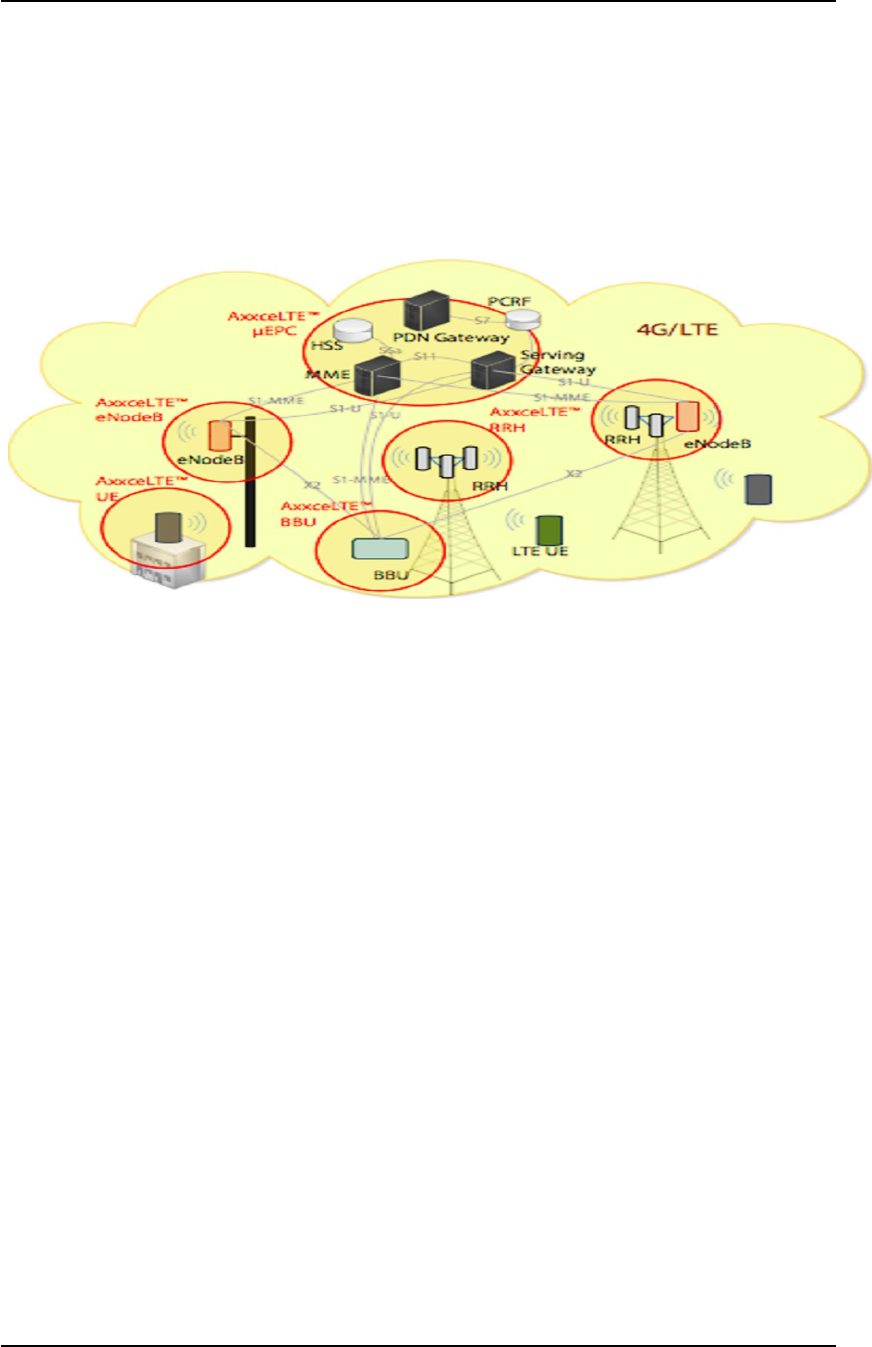
Figure 3.1 shows a typical LTE network architecture using various eNodeB components
at the tower.
Figure 2.1 – Typical LTE Network Architecture
As is shown in the diagram, the eNodeB is typically deployed at the tower, near any
additional RRH units and antennas that it supports. As the BBU is capable of connecting
to three different RRH units, it would be possible to have a BBU located at one site and
have it connect a RRH at a neighboring site via fiber optic cabling.
The S1 interface exits the UPLINK1 / UPLINK2 port(s) which are field serviceable SFP
ports. The two ports can be used for redundant S1 connections or for connecting to 2
different μEPCs.
2.3.2 Time synchronization
Included with the eNodeB is a GPS receiver for time synchronization. Connecting the
receiver to the BBU “GPS” port will allow the eNodeB to synchronize its transmissions
with other eNodeB units in the network.
In addition to GPS, the BBU can synchronize using IEEE 1588, or can accept a 1PPS
clock source via the SYNCIN connector.
Copyright 2015 Axxcelera Broadband Wireless, Inc. All rights reserved
AxxceLTE eNodeB
Installation Guide v1.0 - 7 -
3 Cabling and Interfaces
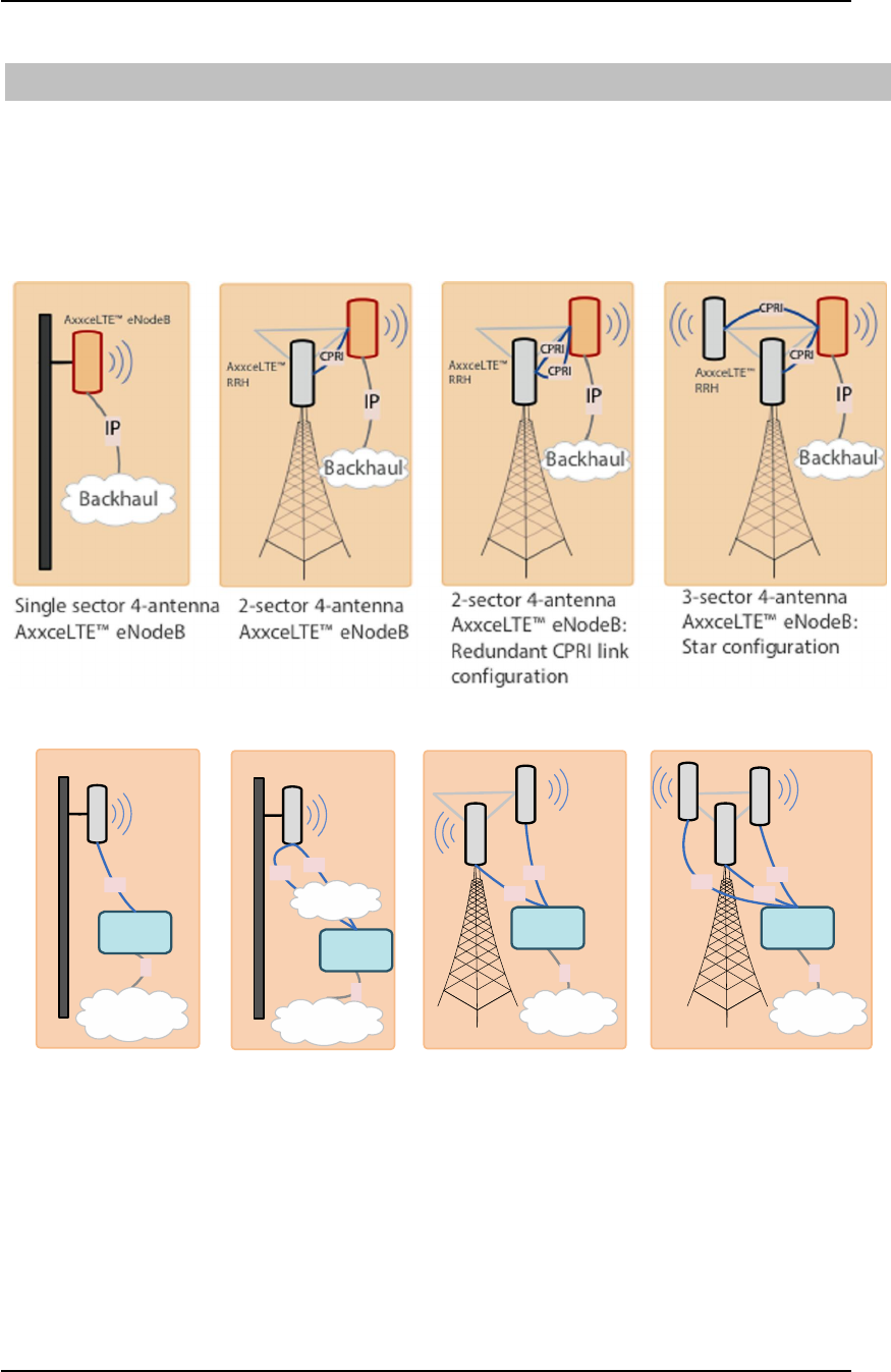
This section outlines and describes the various interfaces on the eNodeB. The system is
designed to be modular in nature and as such, there are many ways the BBU/RRH can be
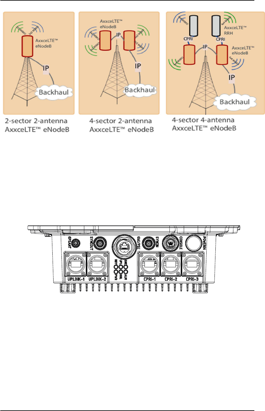
deployed to accomplish the goals of your network design. Figure 5.1 – 5.3 illustrate
several ways the eNodeB can be deployed.
Figure 3.1 – eNodeB Deployment Scenarios
IP
CPRI
Backhaul
CPRI
IP
Backhaul
AxxceLTE™
BBU
CPRI
Single sector 4-antenna
AxxceLTE™ RRH-BBU
2-sector 4-antenna
AxxceLTE™ RRH-BBU:
Star configuration
AxxceLTE™
RRH
AxxceLTE™
RRH
IP
Backhaul
AxxceLTE™
BBU
CPRI
Single sector 4-antenna
AxxceLTE™ RRH-BBU:
Redundant CPRI link
configuration
AxxceLTE™
RRH
CPRI
AxxceLTE™
BBU
IP
CPRI
Backhaul
CPRI
3-sector 4-antenna
AxxceLTE™ RRH-BBU:
Star configuration
AxxceLTE™
RRH
AxxceLTE™
BBU
CPRI
Metro fiber
network
Figure 3.2 – eNodeB Deployment Scenarios (cont.)
Copyright 2015 Axxcelera Broadband Wireless, Inc. All rights reserved
AxxceLTE eNodeB
Installation Guide v1.0 - 8 -
Figure 3.3 – eNodeB Deployment Scenarios (cont)
Depending on how you chose to deploy your BBU/RRH, the cabling can change greatly.
Below is a description of each interface on the eNodeB. Each interface is described with
its function, connector type and typical connection point on the other end of the cable.
This is a guide only and does not attempt to describe every possibility for connection
points.
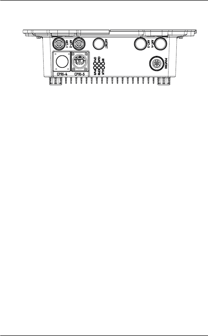
3.1 Base Band Unit (BBU) Connections
Figure 3.4 - Panel Detail for Base Band Unit
GPS ANT:
· Used to connect to an external GPS receiver (included)
· Interface is a standard GPS with an SMA RF connector.
SYNCOUT:
· Used for synchronize to test and certification equipment. Should remain capped
when not in use. Can be configured to output one of several internal reference
signals. Please contact Axxcelera Support for more information if required.

Copyright 2015 Axxcelera Broadband Wireless, Inc. All rights reserved
AxxceLTE eNodeB
Installation Guide v1.0 - 9 -
GbE/PSE:
· May be used as a network connection for an out of band management port. Some
models support the use of Power Devices on this port to power a PoE camera or
similar device for monitoring site conditions.
· Interface is a GbE copper port with an RJ-45 connector. Should remain capped
when not in use.
SYNCIN:
· Can be used to supply a 1PPS synchronization pulse if neither GPS nor IEEE
1588 are available. This is generally used for testing purposes, and the system
must be configured to accept this signal. Please contact Axxcelera Support if
more information is required.
· This port should remain capped when not in use.
CONSOLE:
· Used to console access to the BBU. This is not a customer supported interface
that is used by authorized Axxcelera service engineers only.
· Interface uses a mini USB connector, and should be capped when not in use.
POWERIN:
· The BBU power port is only available when not integrated with an RRH;
otherwise, the power port of the RRH will be used for both sections of the
integrated unit.
· Nominal input voltage is -48VDC. Operable range is -40..-60VDC.
· Uses a supplied, multi-pin circular connector.
UPLINK1:
· Used as the network connection (LTE S1 interface).
· Accepts a field serviceable optical SFP module.
UPLINK2:
· This port may be used as a redundant connection to the PDN or for stacking
multiple BBUs on to the same backhaul pipe. Should be capped if not in use.
CPRI-1 through CPRI-3:
· These CPRI ports are used to connect to one or more remote radio head units.
Connections can be made in a star or daisy-chain topology. Ports support CPRI
v4.1 with a line rate up to 6144 MBps using field upgradable SFP modules for
single- or multi-mode fiber connections.
· Interface uses an optical SFP module and should be capped when not in use.
Copyright 2015 Axxcelera Broadband Wireless, Inc. All rights reserved
AxxceLTE eNodeB
Installation Guide v1.0 - 10 -
3.2 Remote Radio Head (RRH) Connections
Figure 3.5 - Panel Detail for Remote Radio Head
POWERIN:
· Used to connect the RRH or integrated eNodeB to a power source. Nominal input
is -48VDC, with a maximum power consumption of 300watts for an integrated
eNodeB. Operable voltage range is -40..-60VDC.
· Uses a supplied, multi-pin circular connector.
CPRI-4 through CPRI-5:
· These CPRI ports are used to connect to a Baseband Unit and/or to other RRH’s
in a daisy-chain or star topology deployment scenario. These ports support CPRI
v4.1 with a line rate of up to 6144 MBps using field serviceable SFP modules for
single- or multi-mode fiber connections.
· Ports should be capped when not in use.
ANT1 and ANT2:
· These ports are used to connect to antennas via RF Type N connectors in both 2x2
and 4x4 MIMO configurations.
· Interface uses an N-type female connector.
ANT3 and ANT4:
· These ports are used to connect to antennas via RF Type N connectors when
deploying in a 4x4 MIMO configuration.
· Interface uses an N-type female connector. This ports are plugged in units that
only support a single 2x2 configuration. They should be capped if present and not
in use.
ANTRET:
· This port is used when Remote Electrical Tilt is desired for the antenna array.
This interface uses a standard ASIG V2 signal to control electrical tilt device.
· Interface uses an 8-pin DIN connector. RET is an optional feature and this port is
therefore not present on all units. If present, it should be capped when not in use.
Copyright 2015 Axxcelera Broadband Wireless, Inc. All rights reserved
AxxceLTE eNodeB
Installation Guide v1.0 - 11 -
4 Mounting
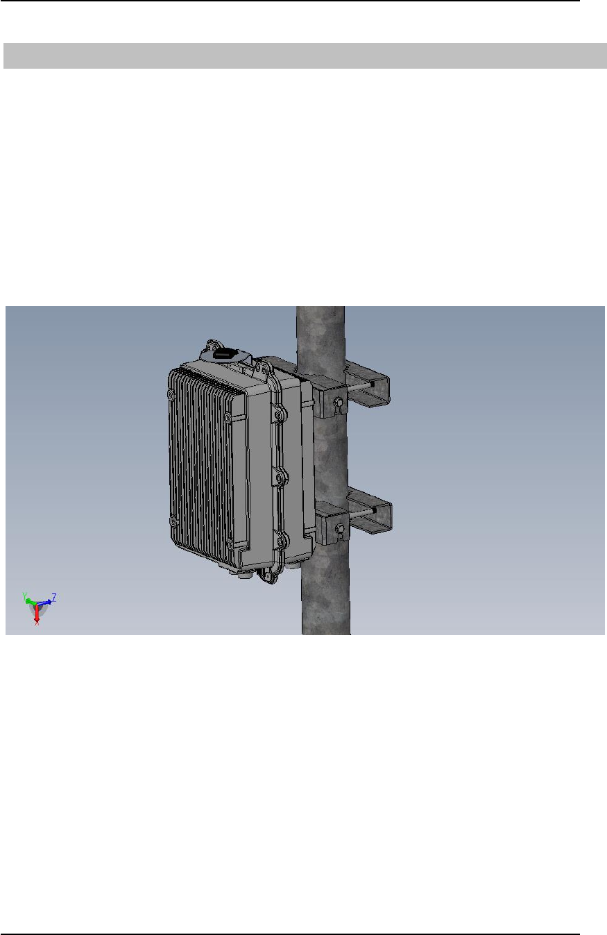
The face of both the RRH and BBU casing have (4) mounting points for attachment to
the hanging brace. The AxxceLTETM eNodeB package includes all necessary mounting
bracket hardware to allow for wall or pole mounting the unit. Instructions for mounting
the eNodeB in either configuration are included with the mounting bracket. Please
follow all instructions provided with the mounting hardware.
Be certain to mount the eNodeB in the direction indicator markings on the case itself.
The connector panel must be on the bottom to minimize any potential water ingress to the
case. Failure to mount the eNodeB properly may result in serious damage to the unit.
Figure 4.1 shows the eNodeB mounted to a pole.
Figure 4.1 – eNodeB Pole Mounted
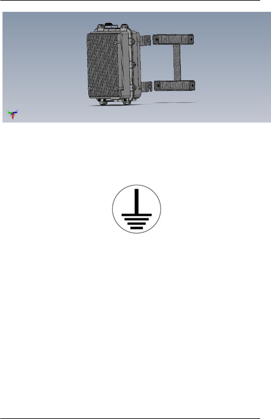
Using the same bracket hardware, the eNodeB can also be mounted to a wall. For wall
mounting, the rear-most part of the bracket and the threaded rods are not used, and the
eNodeB side of the bracket with the stabilizing bar is rotated and mounted to the wall.
Figure 4.2 shows the eNodeB mounted to a wall.
Copyright 2015 Axxcelera Broadband Wireless, Inc. All rights reserved
AxxceLTE eNodeB
Installation Guide v1.0 - 12 -
Figure 4.2 – eNodeB Wall mount
4.1 Grounding
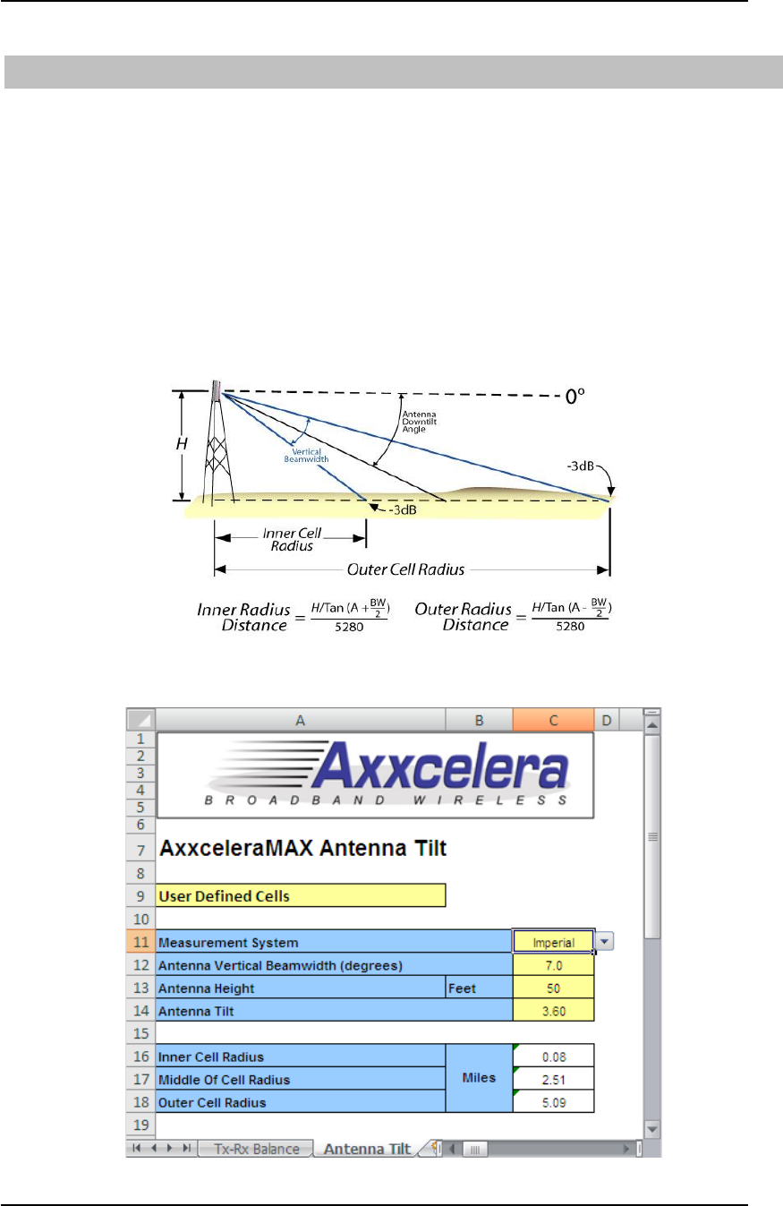
It is required to properly ground the eNodeB. To do this, a ground lug is provided as a
convenient attachment point to the facility grounding plane/grid. It is located on the
bottom seam of the case, labelled with the following mark:
4.2 Sun Shield
AxxceLTE outdoor products are delivered with a sun shield that can be mounted to either
face of the unit using the (4) mounting blocks. The sun shield covers the top, the two
narrow sides, and one face of the unit. The sun shield is delivered with (4) bolts, washers
and locking washers to mount to the face of the unit. Also, (4) mounting extension bolts
are provided for the case that the sun shield needs to be attached to the same face of the
unit as the mounting brace.

Copyright 2015 Axxcelera Broadband Wireless, Inc. All rights reserved
AxxceLTE eNodeB
Installation Guide v1.0 - 13 -
5 Power
NOTE: BEFORE applying power to the eNodeB make absolutely certain that all
antenna ports are properly impedance matched (or are terminated) to avoid costly
damage to the RRH.
The eNodeB operates at a nominal supply voltage of -48VDC and has a maximum power
consumption of 300watts. The operating voltage range is -40..-60VDC. It is highly
recommended that the supply be protected by a Uninterruptable Power Supply that is
capable of outputting clean power to avoid service interruption or potential damage to the
unit.
A multi-pin circular connector is included in the eNodeB package and will need to be
wired correctly to the site supply.
Connect the ground lug on the eNodeB to the facility grounding grid or otherwise
properly ground the unit.

Copyright 2015 Axxcelera Broadband Wireless, Inc. All rights reserved
AxxceLTE eNodeB
Installation Guide v1.0 - 14 -
6 Basic Configuration
Following installation and power up, you are now ready to begin configuring your
eNodeB. This section will outline several basic configuration steps necessary to allow
you to connect to the device. For more detailed configuration information, please see the
AxxceLTE Application Console User Manual.
6.1 Setting the eNodeB IP Address
Once the eNodeB has been installed and power has been applied, you will need to set an
IP address on the device. As previously described, there are two components to the
eNodeB – the BBU and the RRH. Each component requires a unique IP address so it can
be properly managed following installation.
Base Band Unit
To perform a basic configuration of the BBU, use the AxxceLTE Application Console
software to access the device. The default IP address of a base band unit is
192.168.100.200. Change the IP address of the BBU via the Application Console. See
the User Guide for further configuration information.
Remote Radio Head
To perform a basic configuration of the RRH, point a web browser at the device’s default
IP address to access the web management GUI. The default IP address of a remote radio
head is 192.168.100.100
Point your browser at http://192.168.100.100 and enter the credentials:
Username: admin
Password: admin
This will allow you to access management features of the RRH. It is advised to only use
this interface for the purpose of setting the device IP address. Any detailed
configurations should be accomplished using the AxxceLTE Application Console
application.
6.2 Base Band Unit Panel LEDs
Included on the BBU are a set of LED Indicators. The figure below shows the layout of
these LEDs on the bottom panel of the BBU.

Copyright 2015 Axxcelera Broadband Wireless, Inc. All rights reserved
AxxceLTE eNodeB
Installation Guide v1.0 - 15 -
Figure 6.1 – BBU Panel LEDs
The BBU panel LEDs can be valuable in troubleshooting issues encountered in the field.
The following key describes the meaning of the color and sequence (if applicable) of the
indication at each LED.
PWR: Power Status
· Green: All power supplies active
· Red/Green: +12V on, some supplies are not active
· Red: +12V only
· Dark: No Power has been applied, undetermined state.
RDY: CPU Status
· Green Dash: System is alive and in normal operating mode
· Orange Dash: CPU is alive and in non-operational / test mode
· Orange Dot: System is booting
· Red: System boot failed or fatal assertion.
· Dark: No Power has been applied, undetermined state
UPL: Network Uplink Status
· Green Dot: S1 Activity – traffic is being passed over the S1 Interface
· Green: S1 connection has been established
· Orange Dash: S1 connection has been requested
· Orange: S1 GbE Link indicator – indicates that a physical S1 transport has
been established
· Dark: System not up; no S1 connection requested
SNC: Synchronization Status
· Green Dash Dot: AD9548 has Phase and Frequency Lock with sync pulse
· Green Dot: AD9548 has Frequency Lock only
· Green: Sync Pulse lost; AD9548 is in Holdover Mode
· Orange Dash: Sync Pulse present, but AD9548 has not locked yet
· Orange: No Sync Pulse preset; AD9548 in Freerun Mode
· Dark: None of the above
UUL: LTE Uu link status

Copyright 2015 Axxcelera Broadband Wireless, Inc. All rights reserved
AxxceLTE eNodeB
Installation Guide v1.0 - 16 -
· Green Dot: CPRI link active; PDSCH or PUSHC activity
· Green: CPRI link established with RRH; TTI indications received (sub-frame
counter is incrementing); no PDSCH or PUSHC activity detected
· Dark: No TTI indications
ALM: Alarm Status
· Green: No alarms
· Orange: One or more non-fatal alarms are present
· Red: One or more fatal alarms are present
· Dark: No power has been applied, undetermined state
6.3 Remote Radio Head Panel LEDs
Included on the remote radio head are a set of LED Indicators. The figure below shows
the layout of these LEDs on the bottom panel of the RRH.
Figure 6.2 – RRH Panel LEDs
PWR: Power Status
· Green: All power supplies active
· Red/Green: +12V on, some supplies are not active
· Red: +12V only
· Dark: No Power has been applied, undetermined state.
CPU: CPU Status
· Green Dash: CPU is alive and in normal operating mode
· Orange Dash: CPU is alive and in non-operational / test mode
· Orange Dot: CPU booting (including any associated provisioning)
· Red: System boot failed or fatal assertion has occurred
· Dark: No power has been applied, undetermined state
C&M: CPRI Configuration and Management link Status
· Green/Orange: Receive and Transmit
· Orange: Transmit data (min 50ms on)

Copyright 2015 Axxcelera Broadband Wireless, Inc. All rights reserved
AxxceLTE eNodeB
Installation Guide v1.0 - 17 -
· Green: Receive data (min 50ms on)
· Dark: No message
RF: Radio Status
· Green: RF OK; Tx and Rx enabled
· Orange: RF OK; Rx only enabled
· Red Dot: RF OK; Test / non-operational mode
· Red: RF Failure
· Dark: No power has been applied, undetermined state
CPRI: CPRI Link Status
· Green: 6.1440 Gbps link established
· Green Dash: 4.9152 Gbps link established
· Green Dash-Dot: 3.0720 Gbps link established
· Green Dash-Dot x2: 2.4576 Gbps link established
· Green Sash-Dot x3: 1.2288 Gbps link established
· Green Dash-Dot x4: 0.6144 Gbps link established
· Red: Not locked, no CPRI connection
· Dark: No power applied, undetermined state
ALM: Alarm Status
· Green: No alarms present
· Orange: One of more non-fatal alarms present
· Red: One or more fatal alarms present
· Dark: No power has been applied, undetermined state
Copyright 2015 Axxcelera Broadband Wireless, Inc. All rights reserved
AxxceLTE eNodeB
Installation Guide v1.0 - 18 -
7 Antenna Downtilt
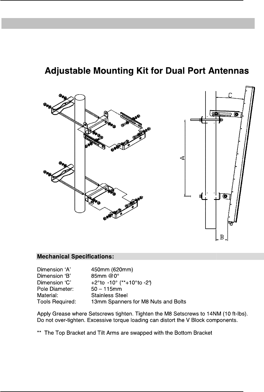
To maximize receive signal levels in the intended coverage area, the downtilt angle
should be calculated before the antenna is mounted. This only applies to directional
antennas at the Cell Site. Omni directional antennas should be mounted perpendicular to
the ground. The antenna tilt angle should be determined based on desired coverage area
and any propagation constraints that were determined during RF planning.
Axxcelera has provided a spreadsheet that will calculate the inner and out cell radius
based on antenna height, antenna pattern, and degrees of downtilt. It is important to
understand that this spreadsheet only calculates the 3dB points of the antenna coverage.
Consult the antenna pattern to determine exact coverage at given offsets outside the 3dB
points.
FIGURE 7.1 – CELL SITE ANTENNA DOWNTILT
FIGURE 7.2 – ANTENNA DOWNTILT SPREADSHEET
Copyright 2015 Axxcelera Broadband Wireless, Inc. All rights reserved
AxxceLTE eNodeB
Installation Guide v1.0 - 19 -
8 Antenna Installation
1. Attach the tilt brackets to the antenna making sure the bracket with the tilt adjustment
slides is installed at the top of the antenna. The top bracket allows -2 to 10 degrees of
downtilt.
2. Once the mounting brackets are installed, attach the antenna to the pole. The clamps
will fit a pole from 48mm – 114mm in diameter.
3. Using an incline meter, verify that the antenna downtilt is the same that is defined in
the RF Plan.