Azden 1200BT WIRELESS MICROPHONE TRANSMITTER User Manual 1200bt instructions
Azden Corporation WIRELESS MICROPHONE TRANSMITTER 1200bt instructions
Azden >
USERS MANUAL
THE 1200BT TRANSMITTER
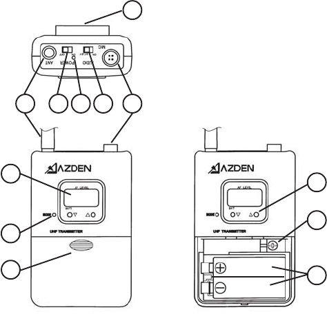
Powering the 1200BT Transmitter
The 1200BT uses two “AA” batteries for power. The batteries are
placed in the battery compartment by sliding the battery compart-
ment door [k] down and placing the batteries in the compartment as
shown in the illustration [♠]. When installing the batteries, be sure to
follow the correct polarity. DO NOT FORCE THE BATTERIES INTO
THE COMPARTMENT. Azden does not recommend the use of re-
chargeable batteries.
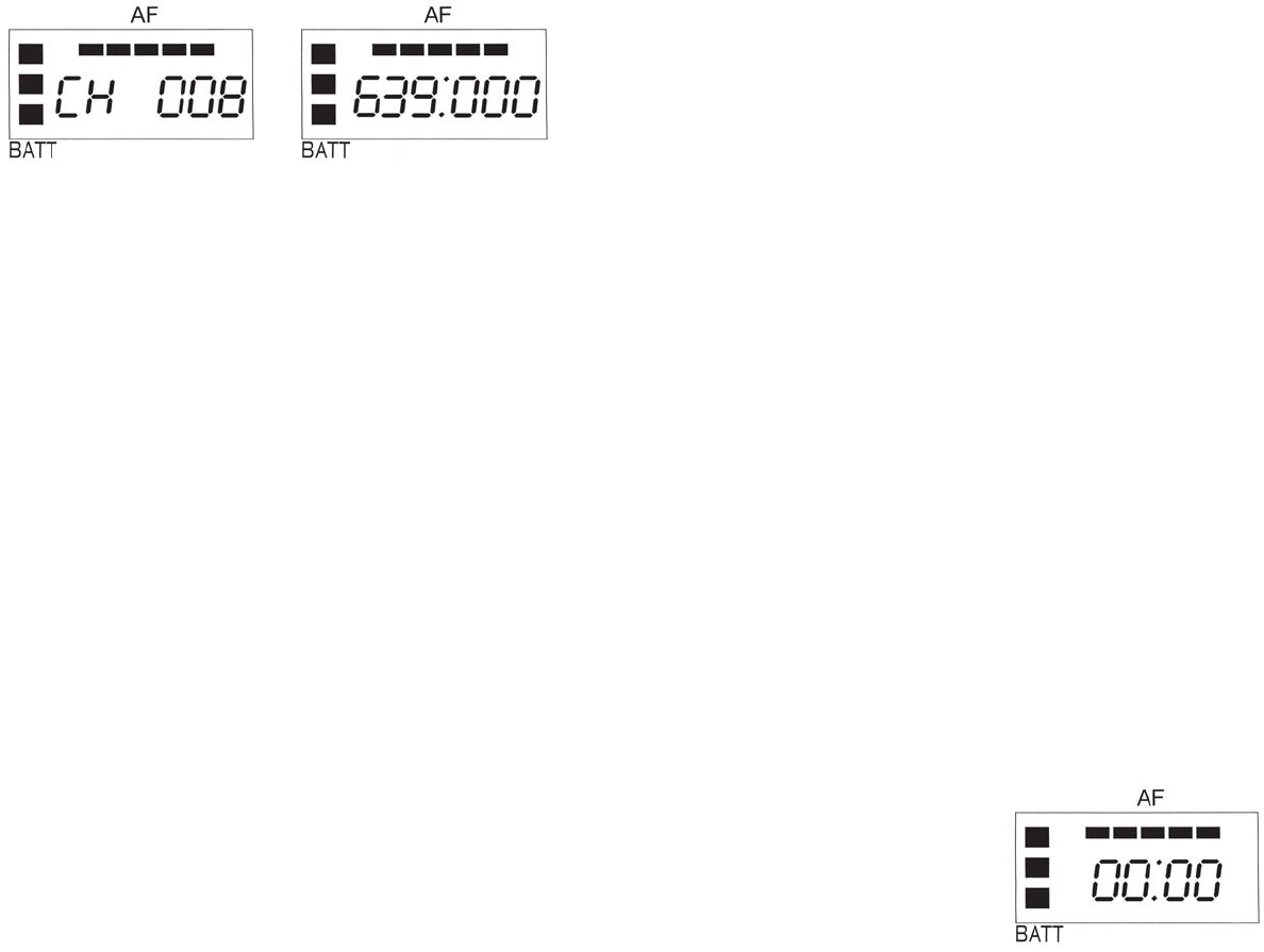
Setting the Transmitting Frequency on the 1200BT
Before the 1200BT can be used, it and the associated receiver have
to set to the same frequency. This can be accomplished on the 1200BT
transmitter by first setting the LCD display to one of two views - ‘Fre-
quency’ or ‘Channel’. To do this, after installing fresh batteries, turn
the 1200BT to the ON position [e]. Next, using the tip of a ballpoint
pen, an unbent paper clip or something similar, press the MODE
button [j] repeatedly until one of the two following screens appears.
G. Display (continued)
life (from 1 to 3 segments) with 3 segments meaning maximum bat-
tery power. The bottom segment will blink when the battery power
falls to less than 2.2V and indicates that it is time to replace the bat-
teries. Azden recommends the use of Alkaline batteries only.
Across the top of the display, up to 5 segments will illuminate de-
pending on the strength of the transmitted audio signal - from 2 (weak)
to 5 (strong). The first (left) segment will light when the ST.BY switch
is turned to ON. The best audio is achieved when 4 to 5 segments
are lit. If all 5 segments are lit continually, the signal is too strong and
could overload the input of the receiver. Either move the microphone
further away from the sound source or reduce the microphone input
gain [♣].
The display can also show the total number of hours of use (change
to this display using the MODE [j] button). To start, after choosing
the TIME mode, press the UP [l] button until the display shows
00:00. Then, each time the transmitter is turned ON the clock will
keep track of the total hours and minutes used. This is a handy way
of keeping track of battery life.
1
234 5 6
7
8
9
10
♣
♠
14
Using either the UP or DOWN button [l] the desired receiving fre-
quency or channel number can be set. Tapping the button steps the
frequency or channel number one at a time while pressing and hold-
ing the button moves through the frequencies or channel numbers
rapidly. There are 188 different frequencies or channel numbers to
chose from. Once the desired frequency or channel has been deter-
mined be certain to set both the transmitter and receiver to match.
Using the 1200BT Transmitter’s Controls and Display
A. Power
The POWER ON/OFF switch [e] turns the 1200BT On or OFF.
B. Audio
Prior to first turning the 1200BT ON it is best to set the AUDIO switch
[g] to ST.BY (standby). When you are ready to begin transmitting,
switch to ON. The ST.BY position acts as a ‘mute’ that maintains the
RF signal but turns off the audio.
C. MIC
This 4-pin Hirose connector [h] is the microphone input. Azden pro-
duces a number of lapel, head-worn and neck-worn microphones
that are specifically suited for the 1200BT. In addition, other exter-
nally powered (5VDC) electret condenser microphones can be used
when they are properly wired with the correct Herosi connector (pin 1
is for audio +, pin 2 is not used, pin 3 is for bias voltage and pin 4 is
ground). If you are using the 1200BT as a wireless instrument trans-
mitter the connections are somewhat different (pin 1 is not used, pin
2 is the audio +, pin 3 is for bias voltage and pin 4 is ground).
D. Input Level Adjustment
This screwdriver adjustment [♣] controls the input level of the micro-
phone. Counterclockwise rotation reduces the input gain while clock-
wise rotation increases the input gain.
E. Belt Clip
The metal beltclip [c] provides a convienent method of attaching
the transmiiter to the user.
F. Antenna
The antenna [d] should be kept clear of metal objects.
G. Display
In addition to showing the frequency and channel number, the dis-
play [i] also shows other useful information.
The LCD segments on the left show the approximate remaining bat-
tery
2 3