Aztech Associates S000-0271 802.11b Modem User Manual Visual Inspection Test Procedure

Aztech Associates Inc. 802.11b Modem Visual Inspection Test Procedure

Contents

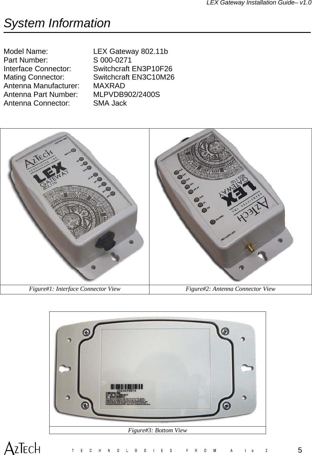
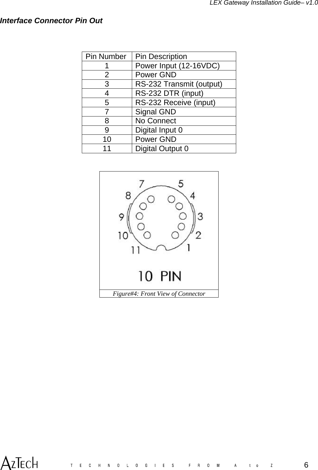
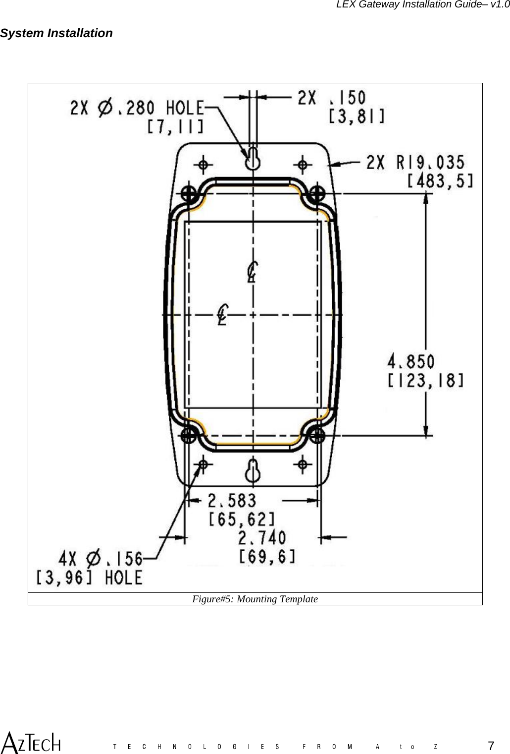
Installation Guide 1

          tel: (613) 384-9400 fax: (613) 384-7139 www.aztechinc.com  805 Bayridge Dr. Kingston, Ontario, Canada K7P 1T5        LEX Gateway Installation Guide  Jan. 3, 05
LEX Gateway Installation Guide– v1.0              Power is conducted. This device is to be used only for mobile and fixed applications. Antenna gain must not exceed 5 dBi. The antenna(s) used for this transmitter must be installed to provide a separation distance of at least 20 cm from all persons and must not be co-located or operating in conjunction with any other antenna or transmitter. Users and installers must be provided with antenna installation instructions and transmitter operating conditions for satisfying RF exposure compliance.   Any changes or modifications not expressly approved by Aztech Associates Inc. could void the user’s authority to operate the equipment.  This product must be professionally installed.   2
LEX Gateway Installation Guide– v1.0 Table of Contents  Table of Contents ................................................................................................................. 3 Table of Figures.................................................................................................................... 4 System Information .............................................................................................................. 5 INTERFACE CONNECTOR PIN OUT......................................................................................................... 6 SYSTEM INSTALLATION ........................................................................................................................ 7  3
LEX Gateway Installation Guide– v1.0 Table of Figures   Figure#1: Interface Connector View ....................................................................................................... 5 Figure#2: Antenna Connector View........................................................................................................ 5 Figure#3: Bottom View........................................................................................................................... 5 Figure#4: Front View of Connector......................................................................................................... 6 Figure#5: Mounting Template................................................................................................................. 7           4
LEX Gateway Installation Guide– v1.0 System Information   Model Name:     LEX Gateway 802.11b Part Number:     S 000-0271  Interface Connector:  Switchcraft EN3P10F26 Mating Connector:    Switchcraft EN3C10M26  Antenna Manufacturer:  MAXRAD Antenna Part Number:  MLPVDB902/2400S Antenna Connector:   SMA Jack     Figure#1: Interface Connector View  Figure#2: Antenna Connector View   Figure#3: Bottom View  5
LEX Gateway Installation Guide– v1.0 Interface Connector Pin Out    Pin Number  Pin Description 1  Power Input (12-16VDC) 2 Power GND 3  RS-232 Transmit (output) 4  RS-232 DTR (input) 5  RS-232 Receive (input) 7 Signal GND 8 No Connect 9  Digital Input 0  10 Power GND 11  Digital Output 0    Figure#4: Front View of Connector      6
LEX Gateway Installation Guide– v1.0 System Installation    Figure#5: Mounting Template     7

Navigation menu