Aztech Technologies DSL5008EN ADSL2+ 4-Ports 150Mbps Wireless-N Modem Router User Manual DSL5008EN v0 1 for Thiha
Aztech Technologies Pte Ltd. ADSL2+ 4-Ports 150Mbps Wireless-N Modem Router DSL5008EN v0 1 for Thiha
Users Manual

DSL5008EN(X)
ADSL2+ 4-Ports 300Mbps Wireless-N
Modem Router

User Manual
Page 2
of 41
© Copyright 2011 All rights reserved.
No part of this document may be reproduced, republished, or retransmitted in any form or by any means
whatsoever, whether electronically or mechanically, including, but not limited to, by way of photocopying,
recording, information recording, or through retrieval systems without the express written permission. We
reserve the right to revise this document at any time without the obligation to notify any person and/or
entity. All other company or product names mentioned are used for identification purposes only and may
be trademarks of their respective owners.
LIMITATION OF LIABILITY AND DAMAGES
THE PRODUCT AND THE SOFTWARES WITHIN ARE PROVIDED "AS IS," BASIS. THE MANUFACTURER AND
MANUFACTURER’S RESELLERS (COLLECTIVELY REFERRED TO AS “THE SELLERS”) DISCLAIM ALL WARRANTIES,
EXPRESS, IMPLIED OR STATUTORY, INCLUDING WITHOUT LIMITATION THE IMPLIED WARRANTIES OF NON-
INFRINGEMENT, MERCHANTABILITY OR FITNESS FOR A PARTICULAR PURPOSE, OR ANY WARRANTIES ARISING
FROM COURSE OF DEALING, COURSE OF PERFORMANCE, OR USAGE OF TRADE. IN NO EVENT WILL THE SELLERS
BE LIABLE FOR DAMAGES OR LOSS, INCLUDING BUT NOT LIMITED TO DIRECT, INDIRECT, SPECIAL WILLFUL,
PUNITIVE, INCIDENTAL, EXEMPLARY, OR CONSEQUENTIAL, DAMAGES, DAMAGES FOR LOSS OF BUSINESS
PROFITS, OR DAMAGES FOR LOSS OF BUSINESS OF ANY CUSTOMER OR ANY THIRD PARTY ARISING OUT OF THE
USE OR THE INABILITY TO USE THE PRODUCT OR THE SOFTWARES, INCLUDING BUT NOT LIMITED TO THOSE
RESULTING FROM DEFECTS IN THE PRODUCT OR SOFTWARE OR DOCUMENTATION, OR LOSS OR INACCURACY OF
DATA OF ANY KIND, WHETHER BASED ON CONTRACT, TORT OR ANY OTHER LEGAL THEORY, EVEN IF THE PARTIES
HAVE BEEN ADVISED OF THE POSSIBILITY OF SUCH DAMAGES. THE ENTIRE RISK AS TO THE RESULTS AND
PERFORMANCE OF THE PRODUCT OR ITS SOFTWARE IS ASSUMED BY CUSTOMER. BECAUSE SOME STATES DO NOT
ALLOW THE EXCLUSION OR LIMITATION OF LIABLITY FOR DAMAGES, THE ABOVE LIMITATION MAY NOT APPLY TO
THE PARTIES. IN NO EVENT WILL THE SELLERS’ TOTAL CUMULATIVE LIABILITY OF EACH AND EVERY KIND IN
RELATION TO THE PRODUCT OR ITS SOFTWARE EXCEED THE AMOUNT PAID BY CUSTOMER FOR THE PRODUCT.

User Manual
Page 3
of 41
Contents
About the Router........................................................................................................ 4
Firmware Features....................................................................................... 5
Requirements.............................................................................................. 8
Package Contents........................................................................................ 8
Device Design.............................................................................................. 9
Front Panel................................................................................................................9
Back Panel...............................................................................................................10
Getting Started......................................................................................................... 11
Planning Your Network ............................................................................. 12
Remove or Disable Conflicts ...................................................................... 13
Internet Sharing, Proxy, and Security Applications...............................................13
Configuring TCP/IP Settings ...................................................................................14
Configuring Internet Properties .............................................................................14
Removing Temporary Internet Files ......................................................................15
Setup the Device ....................................................................................... 16
Connecting to the Internet ........................................................................ 17
Connecting Via Quick Setup....................................................................................17
Advanced Setup ....................................................................................................... 19
Accessing the Advanced Web Interface..................................................... 19
Menus........................................................................................................ 20
Network...................................................................................................................20
Wireless...................................................................................................................26
Applications.............................................................................................................28
System.....................................................................................................................33
Status.......................................................................................................................36
ADSL Status .............................................................................................................36
FCC Notice................................................................................................................. 40

User Manual
Page 4
of 41
About the Router
The Aztech DSL5008EN(X) ADSL2+ 4-ports 300Mbps Wireless-N Modem Router with USB
Host uses complete Ralink chipset solution that fully complies with ADSL2/ADSL2+
standard. The DSL5008EN supports 2T2R with PHY rate up to 300Mbps.
Targeted at the residential and SOHO users that desires high quality triple play services, it
is the ideal solution to provide a 6 in 1 device for both Wired and Wireless connectivity
via a ADSL2+ built in modem, Routing functionality for multi-user sharing, double-layer
NAT/SPI firewall, 4 port 10/100 AutoMDI/MDIx Managed Switch for video application
QoS, high speed IEEE802.11b/g/n Wireless LAN Access point and USB host (optional) for
network printing and NAS.
Aztech DSL5008EN is TR-069 compliant. TR-069 is a DSL forum technical specification
report that defines the remote control/configuration of CPE from ACS (Auto Configuration
Server), TR-069 is also well-known as "CPE WAN Management Protocol". The benefits of
TR-069 include, remote management, auto-configuration, dynamic service activation, as
well as saving cost on customer support and logistics.
Security is provided via a double Stateful Packet Inspection and NAT based firewall.
Hardware accelerated AES/WEP/WPA/WPA2 based encryption/MAC Address Filtering for
Wireless links. Multiple session VPN Pass-through and DMZ support provide additional
security support for telecommuters as well as allow flexibility while maintaining security
against malicious hackers. Dynamic DNS give users the flexibility of hosting a web or an
FTP server with various domain names.
With Universal Plug and Play support, home networking becomes a breeze for everyone
in the family. Multi Port Range/Popular Application Forwarding makes it even easier to
select which application you want your network to allow while ensuring your security at
the same time.

User Manual
Page 5
of 41
Firmware Features
ADSL/ATM
ADSL/ATMADSL/ATM
ADSL/ATM
• ANSI T1.413 issue 2, ITU-T G.992.1 (G.dmt) and G.992.2 (G.lite) compliant
• G.992.3 (ADSL2), G.992.5 (ADSL2+), RE-ADSL2(Annex L)
• Annex A, B, I, J and M
• Support Erasure Decoding and Impulse Noise Monitoring
• Embedded hardware ATM AAL-5 SAR supports UBR, UBR+, CBR and VBR and
GFR traffics
• Configurable USB2.0 EHCI host or device controller
• PCIe gen1 interface for 802.11a/b/g/n WLAN solution
• Multiple PVC up to 8 support
• Spectral compatibility with POTS
• F4 & F5 OAM Loopback/Send and Receive
• TR100 compliant
Encapsulation
EncapsulationEncapsulation
Encapsulation
• RFC2684 Bridge and Routed LLC and VC Mux support
• RFC2364 PPPoA Client support
• RFC2516 PPPoE Client support
• RFC2225/RFC1577 Classical IP Support
• Transparent Bridge Support
• PAP/CHAP/MS-CHAP for Password Authentication Support
Network
NetworkNetwork
Network
• Static IP, Dynamic RIP v1/v2 routing support
• IP/TCP/UDP/ICMP/ARP Application Support
• Network Address Translation (NAT)
• PVC to VLAN Mapping (Future release)
• Port Forwarding/Triggering
• Easy setup of Port Forwarding rules for popular Games/Application
• NAT Application Level Gateway for popular applications
• DHCP Server/Relay/client

User Manual
Page 6
of 41
• DNS Relay Agent
• DMZ support
• SIP ALG (Application Layer Gateway) support
• Multiple Sessions IP Sec and PPTP/L2TP VPN pass through support
• PPP Always on
• PPP Dial on Demand with configurable timeout
• Universal Plug and Play Support
• DDNS (Dynamic DNS) Support
• IGMP Proxy Support (IGMP v1 and v2)
• SNTP Support
• QoS Support (DSCP, TOS), including Diffserv, IEEE802.1p - Priority bit,
IEEE802.1q - VLAN triggering
• PPP/DHCP Auto Detection (Future release)
• TR-069 Compliant
Wireless LAN
Wireless LANWireless LAN
Wireless LAN
• 2x2 Wireless on Board
• IEEE 802.11b/g and IEEE 802.11n compliant
• 2T2R Mode with 300Mbps PHY rate for Both Transmit and Receiving
• Transmit output power up to 20dBm (standard)
• Legacy and High Throughput Modes
• 20MHz/40MHz Bandwidth
• Reverse Direction Grant Data Flow and Frame Aggregation
• Frequency Band:
- 2412 MHz - 2462 MHz (North America/FCC)
- 2412 MHz - 2472 MHz (ETSI/Europe)
- 2412 MHz - 2484 MHz (Japan)
- 2457 MHz - 2472 MHz (France)
- 2457 MHz – 2462 MHz (Spain)
• Support Direct Sequence Spread Spectrum (DSSS) technology
• Modulation: OFDM with BPSK, QPSK, 16QAM, 64QAM, DBPSK, DQPSK, CCK
• Wireless Media Access Protocol- CSMA/CA with ACK
• WEP 64/128, WPA, WPA2, TKIP, AES
• QoS-WMM, WMM-PS

User Manual
Page 7
of 41
• WPS support
• Cisco CCX Support (optional)
• Operating Range of >300 Meters (Open Air)
• WDS Support (optional)
• MAC Address Filtering
• Multiple BSSID Support (optional)
• Low Power and Advanced Power Management
Management
ManagementManagement
Management
• Web Based HTTP management GUI
• TFTP/FTP Support for Firmware Upgrade
• Web Based Firmware Upgrade (Local)
• Soft Factory Reset Button via Web GUI
• Diagnostic Test (DSL, OAM (ADSL), Network (ADSL), Ping Test)
• TR068 - WAN Access
• Telnet with CLI (Read and Write) configuration
• Syslog Support
• Firmware upgrade-able for future feature enhancement
• Quick firmware upgrade button (population option)
• TR-069 (include TR-098, TR-111)
• SNMP v1 and v2
• TR-143
• SSH Support (optional)
Security
Security Security
Security
• NAT for basic Firewall support
• Packet Filtering Firewall Support
• Stateful Packet Inspection Support
• Protection against Denial of Service attacks
• Password Authentication to Modem
• URL filtering/ Parental Control (optional)
• Real-Time Attack and Alert Logs (optional)

User Manual
Page 8
of 41
Requirements
Your computer must meet the following minimum requirements.
Any operating system can be used
Web Browser
CDROM drive
233MHz processor
Ethernet network adapter
An active DSL Internet account
Package Contents
Package contents are listed below. For any missing items, please contact your dealer
immediately. Product contents vary for different models.
Router
Ethernet cable
Telephone cable
POTS Splitter (optional)
12V 1.0A DC Power Adapter
Easy Start Guide
Resource CD

User Manual
Page 9
of 41
Device Design
Front Panel
Label
LabelLabel
Label
Icon
IconIcon
Icon
Action
ActionAction
Action
Description
DescriptionDescription
Description
1
WIRELESS ON/OFF button/LED
WIRELESS ON/OFF button/LEDWIRELESS ON/OFF button/LED
WIRELESS ON/OFF button/LED
Off
Steady green
Wireless interface disabled
Wireless interface enabled
2
POWER
POWERPOWER
POWER
Off
Steady green
Steady red
No power is supplied to the device
Connected to an AC power supply
Error on the device
3
ETHERNET LAN 1
ETHERNET LAN 1ETHERNET LAN 1
ETHERNET LAN 1-
--
-4
44
4
Off
Steady green
Blinking green
No Ethernet connection
Connected to an Ethernet port
Transmitting/Receiving data
4
USB Host
USB HostUSB Host
USB Host
Off
Steady green
No USB device connected
USB device connected
5
WIRELESS
WIRELESSWIRELESS
WIRELESS
Off
Steady green
Blinking green
Wireless interface disabled
Wireless Interface enabled
Transmitting/Receiving data
6
BROADBAND
BROADBANDBROADBAND
BROADBAND
Blinking green
Steady green
Establishing or No DSL signal
DSL signal is established
7
INTERNET
INTERNETINTERNET
INTERNET
Off
Steady green
Blinking green
Steady red
No connection to the Internet
Internet connection established
Transmitting/Receiving data
PPP authentication failed
8
WPS button
WPS buttonWPS button
WPS button
Off
Blinking green
WPS off or idle
WPS association on going
User Manual
Page 10
of 41
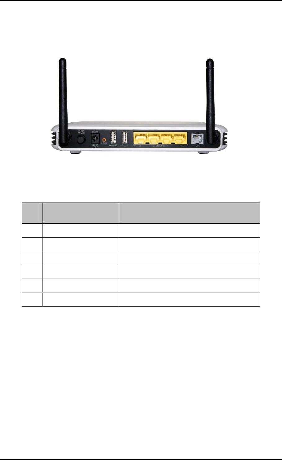
Back Panel
Label
LabelLabel
Label
Description
DescriptionDescription
Description
9
99
9
POWER
POWERPOWER
POWER
Power ON/OFF button
10
1010
10
DC In
DC InDC In
DC In
12V 1.0A DC Input port
11
1111
11
RESET
RESETRESET
RESET
To reset the modem to the factory default configuration
12
1212
12
USB
USBUSB
USB
For USB devices such as printers and USB external hard drives
13
1313
13
ETHERNET 1
ETHERNET 1 ETHERNET 1
ETHERNET 1 -
--
- 4
4 4
4
Connecting computers and other Ethernet devices
14
1414
14
BROADBAND
BROADBANDBROADBAND
BROADBAND
Connecting the modem to an ADSL line

User Manual
Page 11
of 41
Getting Started
Setting up the device is easy. The flowchart below provides an outline of the steps
needed to complete the installation. Brief descriptions appear beside each step. Detailed
instructions are provided in the subsequent pages.
Remove/Disable
Conflicts
Plan your Network
Ready to Use
Setup the Router
Connect to the
Internet
Web Interface
Use Quick Setup
You may need to check some
setting or disable some application
before installation.
Connect the telephone cables,
Ethernet cables, and power adaptor.
Use the Quick Start Web GUI to setup
your PPPoE connection.
User Manual
Page 12
of 41
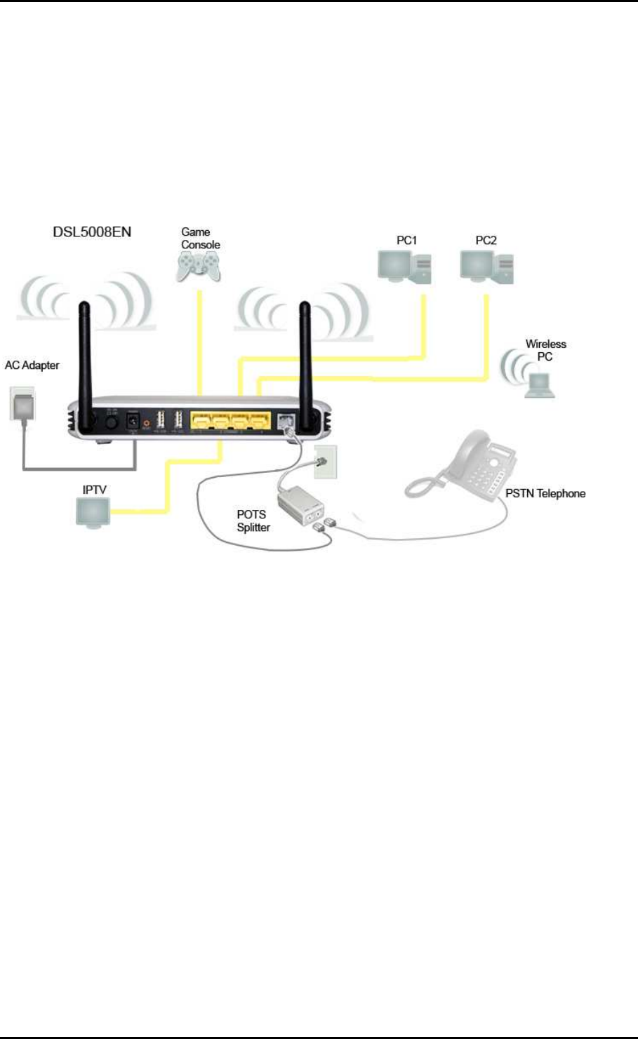
Planning Your Network
Before moving ahead to setup your network, it is a good idea to draw out a network
diagram to help identify your network devices and plan out how to connect these
devices. The illustration below is an example of a network diagram.
Each port in the router can be used for different connections. For example:
• Ethernet 1 – Game Console
• Ethernet 2 – Dad’s Computer (PC1)
• Ethernet 3 – Mom’s Computer (PC2)
• Ethernet 4 – IPTV Set Top Box
To create a network diagram:
To create a network diagram:To create a network diagram:
To create a network diagram:
• For wireless devices, identify the wireless devices you want to include in the
network
• For wired devices, identify which router port you want to use for each device.

User Manual
Page 13
of 41
Remove or Disable Conflicts
To make sure the router installation moves on smoothly, you need to remove or disable
conflicts that may interfere the installation. Probable conflicts may include:
Internet sharing applications
Proxy software
Security software
TCP/IP settings
Internet properties
Temporary Internet files
Internet Sharing, Proxy, and Security Applications
Internet sharing, proxy software, and firewall applications may interfere with the router
installation. These should be removed or disabled before start the installation.
If you have any of the following or similar applications installed on your computer,
remove or disable them according to the manufacturer’s instructions.
Internet Sharing Applications
Internet Sharing ApplicationsInternet Sharing Applications
Internet Sharing Applications
Proxy Software
Proxy SoftwareProxy Software
Proxy Software
Security Software
Security SoftwareSecurity Software
Security Software
Microsoft Internet Sharing WinGate Symantec
WinProxy Zone Alarm

User Manual
Page 14
of 41
Configuring TCP/IP Settings
Check if your computer uses the default TCP/IP settings.
To check the TCP/IP properties:
1. Select Start > Run. This opens the Run dialog box.
2. Enter control ncpa.cpl and then click OK. This opens the Network Connections in
your computer.
3. Right-click LAN and then select Properties. This opens the Local Area Connection
Properties dialog box.
4. Select Internet Protocol (TCP/IP) and then click Properties. This opens the Internet
Protocol (TCP/IP) dialog box.
5. Select Obtain an IP address automatically.
6. Click OK to close the Internet Protocol (TCP/IP) dialog box.
7. Click OK to close the Local Area Connection Properties dialog box.
Configuring Internet Properties
To set the Internet Properties:
1. Select Start > Run. This opens the Run dialog box.
2. Enter control inetcpl.cpl and then click OK. This opens Internet Properties.
3. Click Connections tab.
4. In the Dial-up and Virtual Private Network settings pane, select Never dial a
connection.
5. Click OK to close Internet Properties.

User Manual
Page 15
of 41
Removing Temporary Internet Files
Temporary Internet files are files from Web sites that are stored in your computer. Delete
these files to clean the cache and remove footprints left by the Web pages you visited.
To remove temporary Internet files:
1. Select Start > Run. This opens the Run dialog box.
2. Enter control and then click OK. This opens Control Panel.
3. Double-click Internet Options. This opens Internet Options.
4. In the Temporary Internet Files pane, click Delete Cookies.
5. Click Delete Files.
6. Click OK to close Internet Properties.

User Manual
Page 16
of 41
Setup the Device
When installing the router, find an area where there are enough electrical outlets for the
router, the main computer, and your other computer devices.
To setup the router:
1. Plug one end of the Ethernet cable from the router’s ETHERNET
ETHERNET ETHERNET
ETHERNET port and then plug
the other end into the Ethernet port in your computer.
2. If you have another device you need to connect through wire into the router, use
another piece of Ethernet cable. Plug one end of the Ethernet cable from the
computer’s Ethernet port and then plug the other end into an available Ethernet
port in the router.
3. Plug one end of the telephone cable from the POTS Splitter’s ADSL
ADSL ADSL
ADSL port and then
plug the other end into the router’s DSL
DSL DSL
DSL port.
POTS Splitter
POTS SplitterPOTS Splitter
POTS Splitter
Your phone line carries with it both phone calls and Internet signals. When you are
using the Internet, the connection produces high-pitched tones that can affect your
voice calls when using the phone. Installing a Plain Old Telephone Service (POTS)
splitter separates the two signals and eliminates the noise.
To setup a telephone on the POTS Splitter:
To setup a telephone on the POTS Splitter:To setup a telephone on the POTS Splitter:
To setup a telephone on the POTS Splitter:
a. Locate the phone jack in your house.
b. Insert the POTS Splitter into the phone jack.
c. Plug one end of the telephone cable from the POTS Splitter’s TEL
TELTEL
TEL port and then plug
the other end into the telephone.
4. Connect the power adapter from the router’s 12V 1.0A DC
port into the electrical
outlet.
5. Press ON.
User Manual
Page 17
of 41
Connecting to the Internet
You can use the Web Interface to setup your Internet connection.
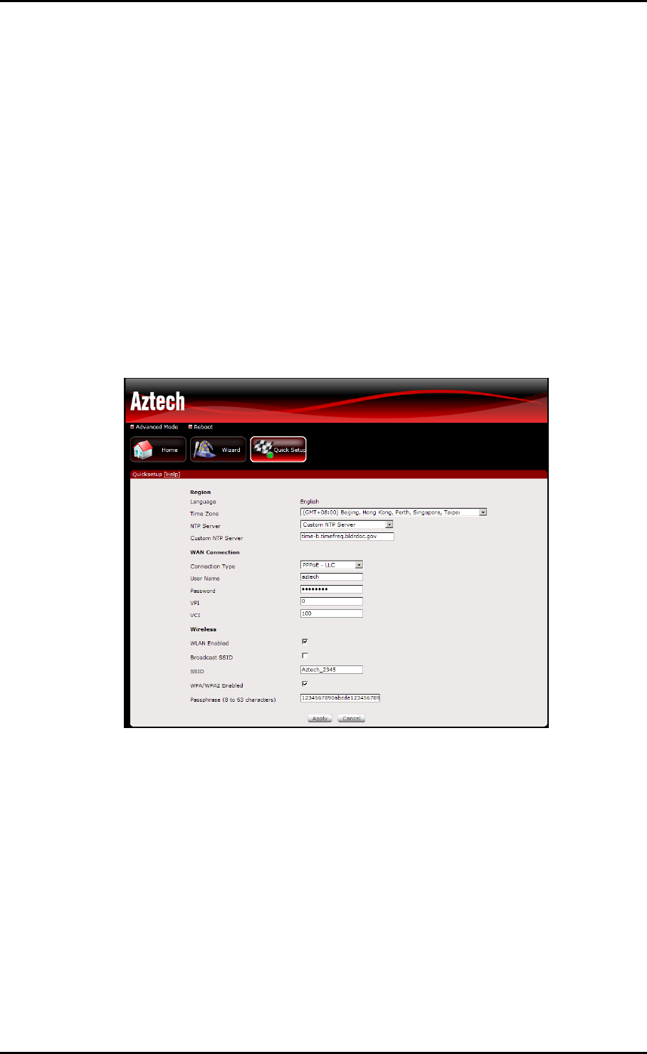
Connecting Via Quick Setup
To connect to the Internet via the User mode GUI:
1. Launch the web browser and input 192.168.1.1 on the address bar.
2. Input admin for username and input admin for password. Click the Login button.
3. Click Quick Setup.
4. Enter the Region settings.
a. Select your Time Zone
b. Select an NTP server
5. Enter the WAN connection settings.
c. Select a Connection Type
d. Enter the PPP Username and Password
e. Enter the VPI and VCI configuration (This information will come from your
Internet Service Provider)

User Manual
Page 18
of 41
6. Enter the Wireless Settings.
f. Ensure that WLAN Enabled and Broadcast SSID are checked
g. Enter your desired Wireless Network Name or SSID
h. Put a check on WPA/WPA2 Enabled to setup a secured wireless network
i. Enter your desired wireless password or Passphrase
7. Click the Apply button to commit the settings.
To connect to the Internet via the Web Interface Setup Wizard:
1. Launch the web browser and input 192.168.1.1 on the address bar.
2. Input admin for username and input admin for password. Click the Login button.
3. Click Wizard and read the onscreen instructions, then click Next
4. Enter the Region settings.
a. Select your Time Zone
b. Select an NTP server
5. Enter the WAN connection settings.
c. Select a Connection Type
d. Enter the PPP Username and Password
e. Enter the VPI and VCI configuration (This information will come from your
Internet Service Provider)
6. Enter the Wireless Settings.
f. Ensure that WLAN Enabled and Broadcast SSID are checked
g. Enter your desired Wireless Network Name or SSID
h. Put a check on WPA/WPA2 Enabled to setup a secured wireless network
i. Enter your desired wireless password or Passphrase
7. Review all the settings on the Summary page.
8. Click the Apply button to commit the settings.
User Manual
Page 19
of 41
Advanced Setup
Advanced Setup provides configuration options for other router functions.
Accessing the Advanced Web Interface
To access the Advanced Web Interface:
1. Launch your web browser.
2. Input 192.168.1.1 on the address bar and press Enter.
3. There will be an authentication request where you need to key in a username and
password. Default Username: admin | Password: admin
4. Click Login
5. Click Advanced Mode

User Manual
Page 20
of 41
Menus
The Web User Interface includes the following menus:
Network
Wireless
Applications
System
Status
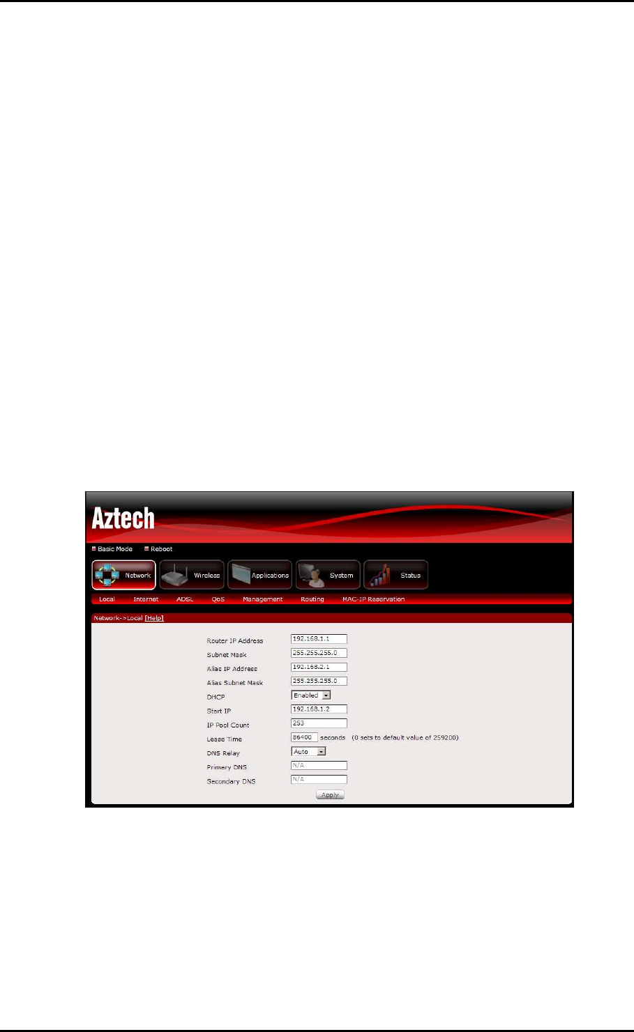
Network
Local
Configure the DSL Router IP Address and Subnet Mask for LAN interface. You may also
configure the DHCP server settings of your router.
User Manual
Page 21
of 41
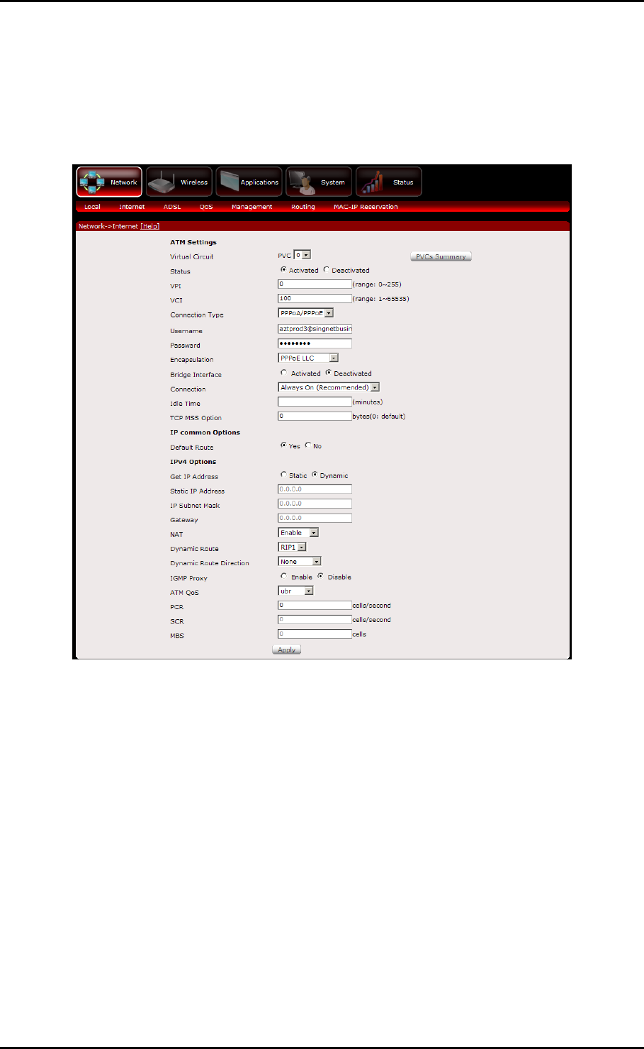
Internet
The initial page will show all the settings of your existing WAN connection configured on
your router. You have an option to Add and Edit WAN interface configurations.
To add a WAN interface:
1. Select an available Virtual Circuit from the drop-down box
2. Enter VPI/VCI settings (provided by your ISP)
3. Select the WAN Connection Type
4. Enter PPP Username and Password (provided by your ISP)
5. Ensure Default Route is selected as Yes
6. Ensure Get IP Address is set to Dynamic
7. Click the Apply button to commit the settings
User Manual
Page 22
of 41
To edit an existing WAN interface:
1. Select the Virtual Circuit that you want to Edit from the drop down box
2. Make the necessary amendments
3. Click the Apply button to commit the settings
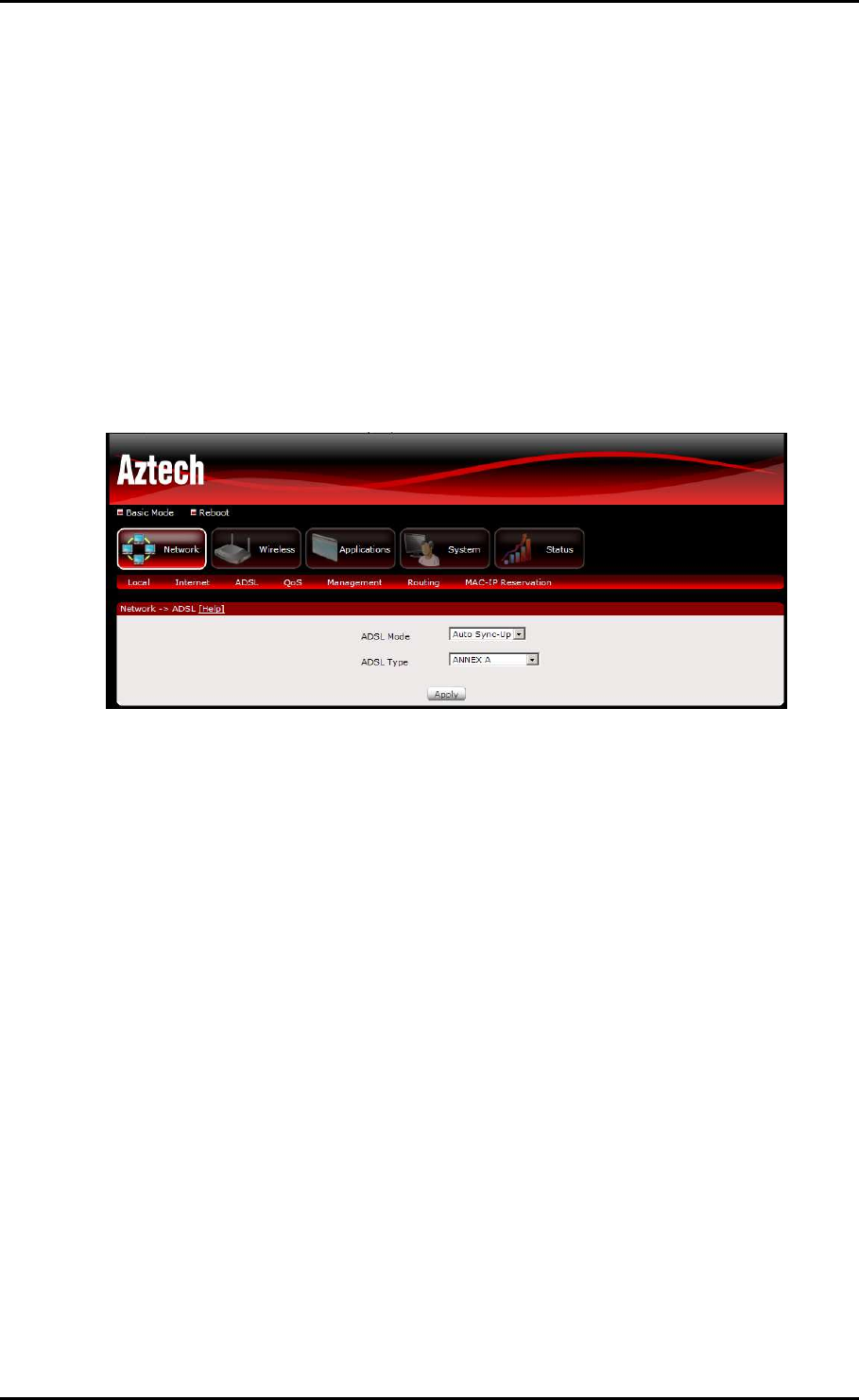
ADSL Settings
The DSL page allows you to select the modulation, the phone line pair and the capability.
Quality of Service
Quality of Service or QoS provides different priority to different applications, users, or
data flows, to guarantee a certain level of performance. For example, QoS is important
for real-time streaming multimedia applications such as voice over IP, online games and
IPTV to provide fixed bit rate and prevent delay.

User Manual
Page 23
of 41
Management
TR
TRTR
TR-
--
-069 client
069 client 069 client
069 client –
––
– Configuration (CWMP)
Configuration (CWMP) Configuration (CWMP)
Configuration (CWMP)
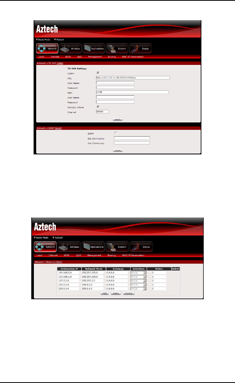
WAN Management Protocol (TR-069) allows an Auto-Configuration Server (ACS) to
perform auto-configuration, provision, collection, and diagnostics to this device.
Select the desired values and click "Apply" to configure the TR-069 client options
.
User Manual
Page 24
of 41
Routing
If your LAN consists of multiple subnets and you want to manually define the data
transmitting paths, Static Route is to be used.
The key settings for adding a new Static Route are explained:
Destination Network Address
Destination Network Address Destination Network Address
Destination Network Address Enter the network address to which the data packets
are to be sent.
Subnet Mask
Subnet Mask Subnet Mask
Subnet Mask Enter the subnet mask for this destination.
User Manual
Page 25
of 41
Use Gateway IP Address
Use Gateway IP Address Use Gateway IP Address
Use Gateway IP Address If you wish to use a specific gateway to reach the
destination network, select this checkbox and then enter the IP address of the
gateway.
Use Interface
Use Interface Use Interface
Use Interface If you wish to use a particular WAN interface, select the checkbox
and select the interface.
Click Save/Apply to take effect the settings.
To delete the entry from the routing table list, click its corresponding Delete button.
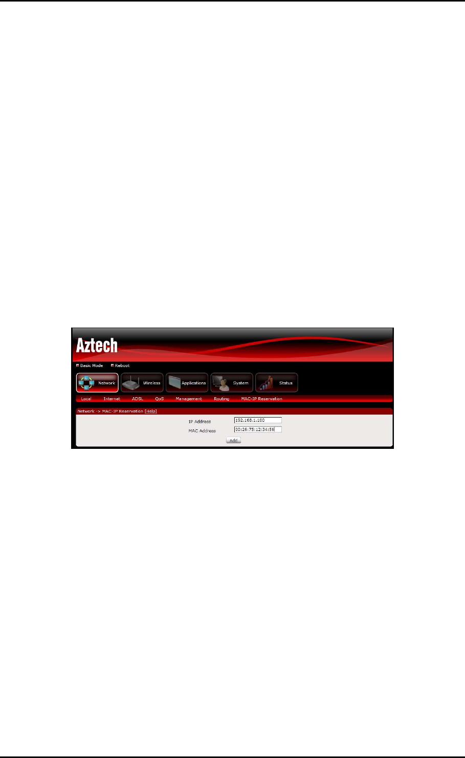
MAC-IP Reservation
The initial page allows you to assign a specific IP address to a specific device by entering
its MAC address.
To Manually reserve a LAN IP address:
1. Key in the PC’s MAC address
2. Key in the LAN IP Address you want to assign
3. Click the Add button
User Manual
Page 26
of 41
Wireless
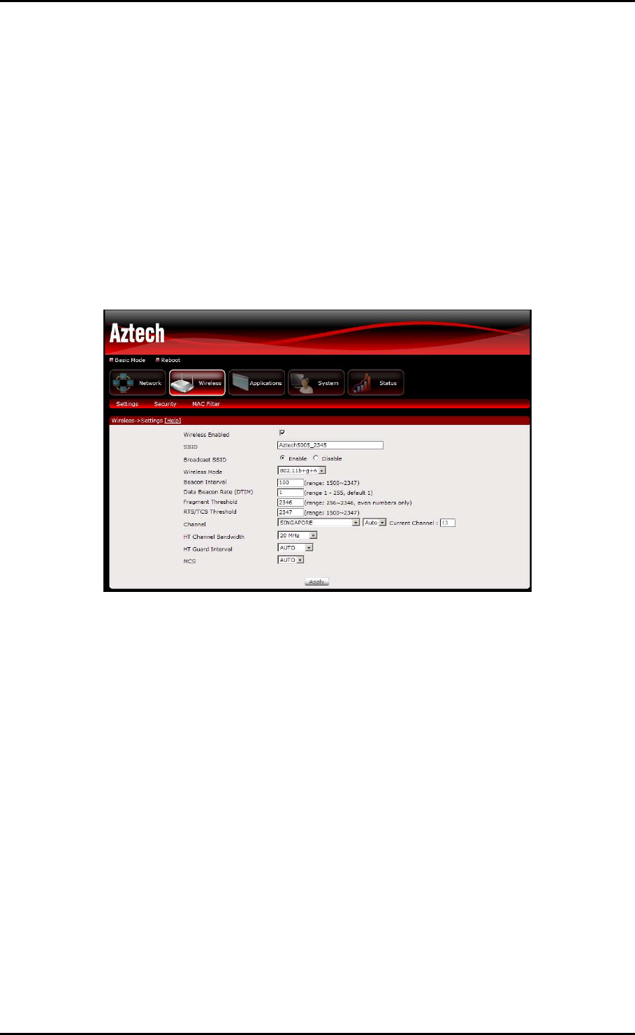
Settings
This page allows you to configure basic features of the wireless LAN interface. You can
enable or disable the wireless LAN interface, hide the network from active scans, set the
wireless network name (also known as SSID), restrict the channel set based on country
requirements, and all other configurations relating to the wireless LAN interface.
Click Apply to commit the wireless settings.
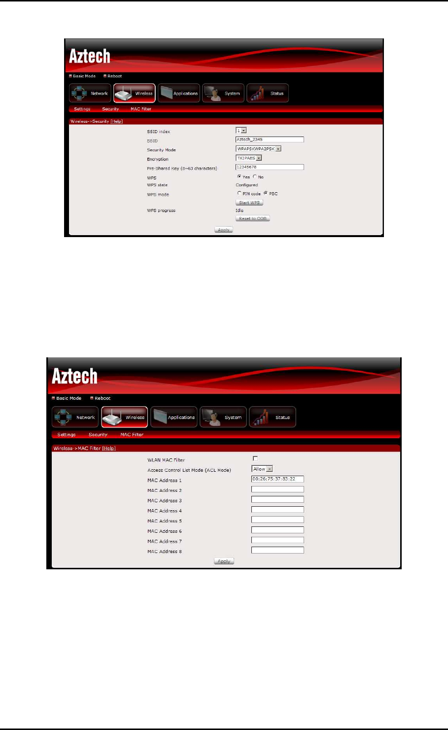
Security
This page allows you to set the network authentication method, selecting data
encryption, specify whether a network key is required to authenticate to this wireless
network and specify the encryption strength.
Click "Apply" to commit wireless security settings.
User Manual
Page 27
of 41
MAC Filter
This page allows you to set a filter to Allow or Deny specific wireless clients by entering
the MAC address and selecting the Access Control List mode.
User Manual
Page 28
of 41
Applications
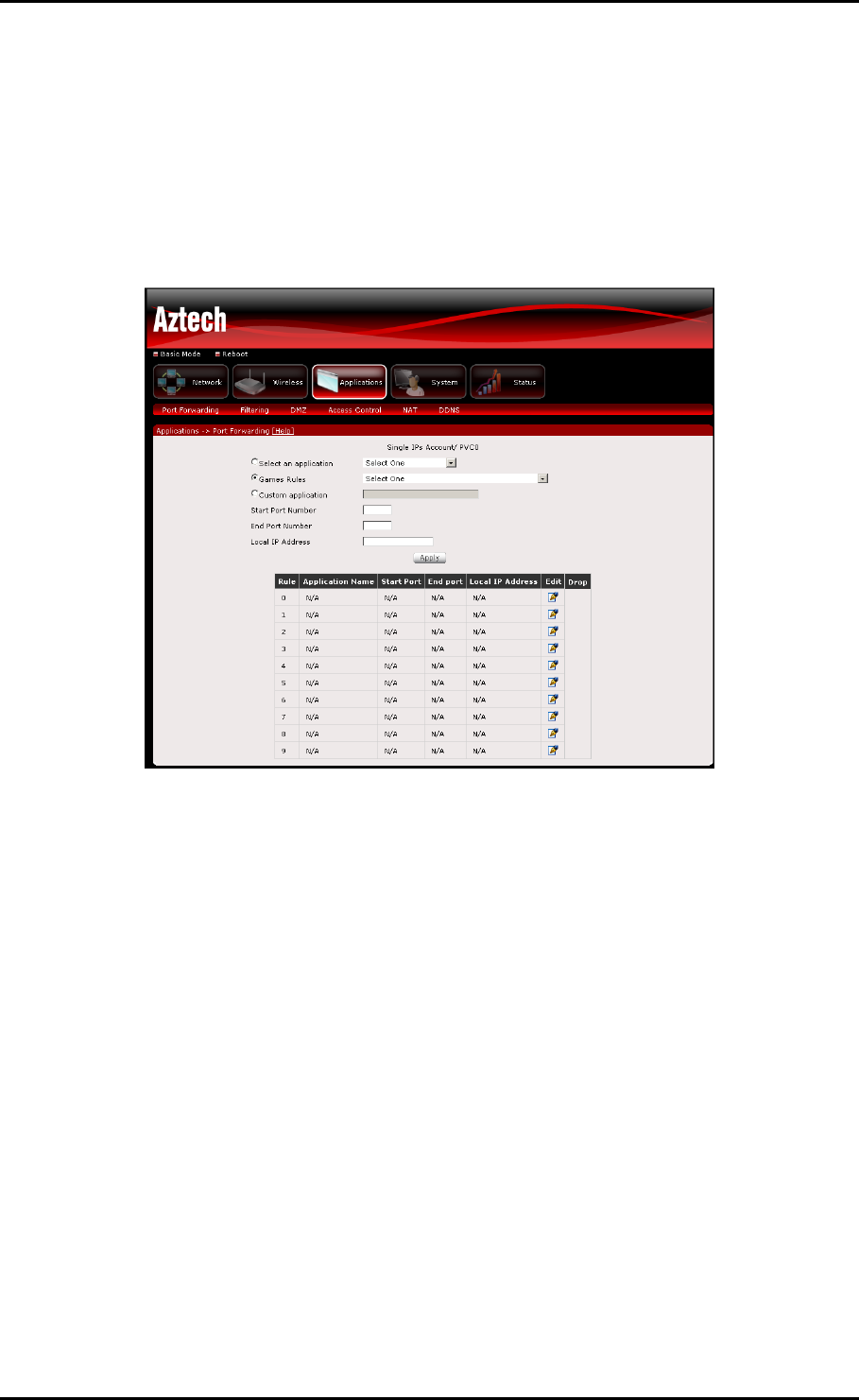
Port Forwarding
Port Forwarding allows you to direct incoming traffic from the Internet to a specific
computer in your local network. A maximum 9 entries can be configured.
As an example, to setup a web server on a computer using 192.168.1.88 as its IP
Address, select HTTP as Service and enter 192.168.1.88 as the Server IP Address.
Otherwise if the service you want to setup is not available from the Select a Service
drop-down list, you can define your own Port Forwarding rule.
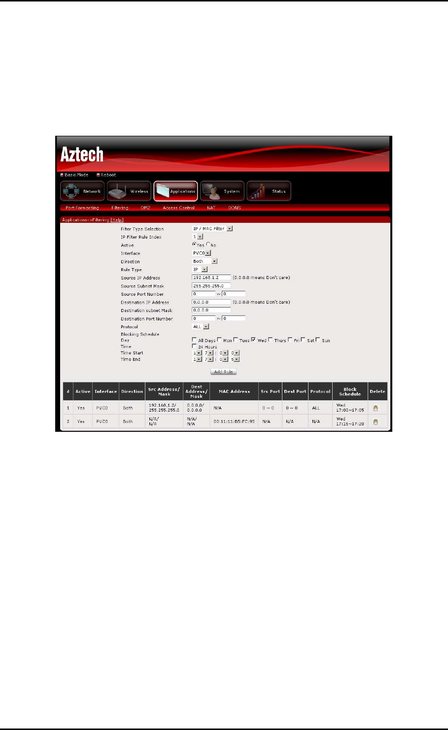
IP Filtering
The router supports IP Filtering, which allows you to easily set up rules to control
incoming and outgoing Internet traffic. The router provides two types of IP filtering:
Outgoing IP Filtering and Incoming IP Filtering. Choose IP from the Rule Type drop down
box to configure IP Filtering.
User Manual
Page 29
of 41
MAC Filtering
The router supports MAC Filtering, which allows you to easily set up rules to control
incoming and outgoing Internet traffic. Choose MAC from the Rule Type drop down box to
configure MAC Filtering.
Key in the following parameters:
IP Filter Rule Index
IP Filter Rule Index IP Filter Rule Index
IP Filter Rule Index Select the index of the filter rule.
Interface
Interface Interface
Interface Select the WAN interface for filter rule.
Direction
Direction Direction
Direction Select the direction of the filter rule.
Source IP Address/Subnet Mask
Source IP Address/Subnet Mask Source IP Address/Subnet Mask
Source IP Address/Subnet Mask Enter the IP address of the PC on the LAN to
block.
Source Port
Source Port Source Port
Source Port Enter the port number used by the application to block.
Destination IP Address/Subnet Mask
Destination IP Address/Subnet Mask Destination IP Address/Subnet Mask
Destination IP Address/Subnet Mask Enter the IP address of the remote server to
which connection should be blocked.
Destination Port
Destination Port Destination Port
Destination Port Enter the destination port number used by the application to
block.

User Manual
Page 30
of 41
Protocol
Protocol Protocol
Protocol Select the IP protocol to block.
Click Save/Apply to take effect the settings. The new rule will then be displayed
in the Outgoing IP Filtering table list.
Click Delete button to delete a corresponding rule.
Blocking Control (Parental Control)
Parental Control allows you to apply router access restrictions among LAN devices within
specific times in a day. A maximum of 16 restriction rules can be created.
Key in the following parameters:
Day
Day Day
Day Click to select the days on which to apply the restriction.
Time Start (Blocking Time) (hh:mm)
Time Start (Blocking Time) (hh:mm) Time Start (Blocking Time) (hh:mm)
Time Start (Blocking Time) (hh:mm) Enter the time when the restriction will be enabled
(00:00 to 23:59).
Time End (Blocking Time) (hh:mm)
Time End (Blocking Time) (hh:mm) Time End (Blocking Time) (hh:mm)
Time End (Blocking Time) (hh:mm) Enter the time when the restriction will be disabled
(00:00 to 23:59).
Application Filter
Application Filter provides control on popular applications to be allowed or denied access
to local clients. Check the box of applications that you want to allow to be accessed by
local clients and uncheck those that you want to deny.
User Manual
Page 31
of 41
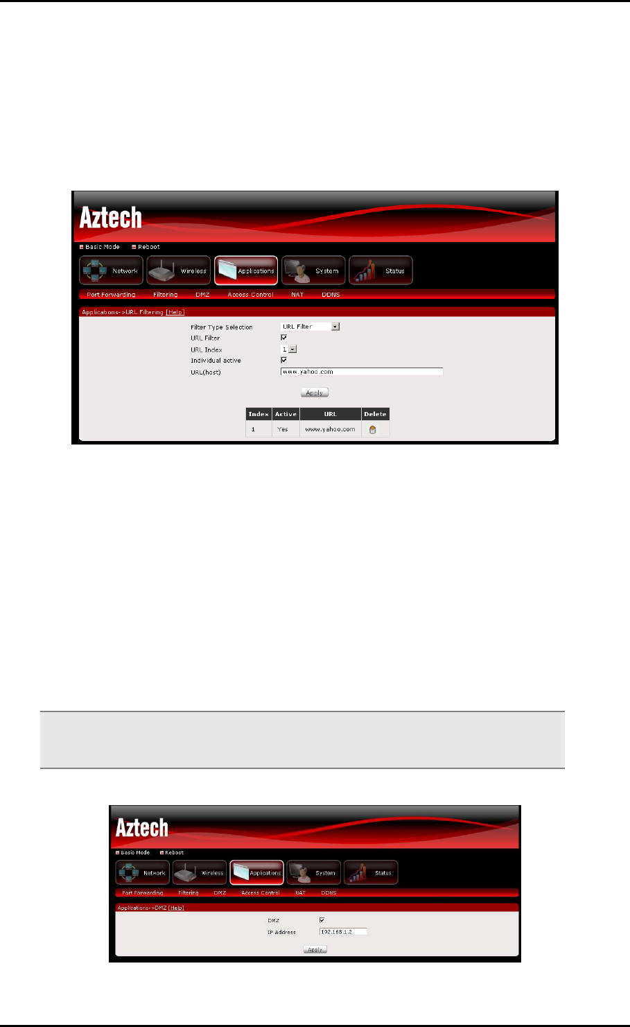
URL Filter
URL Filter enables you to block certain websites. Select a URL Index, activate the service,
and enter the URL of the website that you want to block. Click the Apply button to
commit the settings. A maximum of 16 entries can be configured.
Click Delete button to delete a corresponding rule.
DMZ Host
If a computer is assigned as a DMZ Host, it will receive all the data from the Internet that
do not belong to the list of applications configured in Port Forwarding. Enter the LAN IP
address of the PC you wish to set as DMZ Host in the provided box. If you need to disable
the DMZ Host, just click the remove button.
Note:
Note: Note:
Note: DMZ exposes your computer to the Internet and will be vulnerable to malicious
attacks.
User Manual
Page 32
of 41
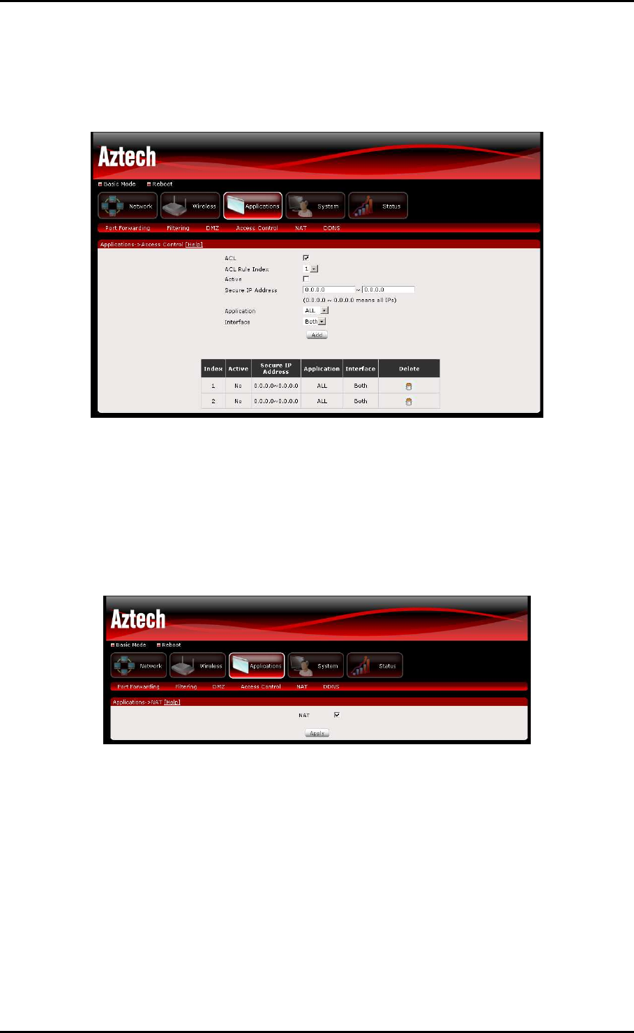
Access Control
Select which Services to allow and whether to allow from the LAN or the WAN.
Click Delete button to delete a corresponding rule.
NAT (Network Address Translation)
This page allows you to enable/disable NAT on the modem-router.
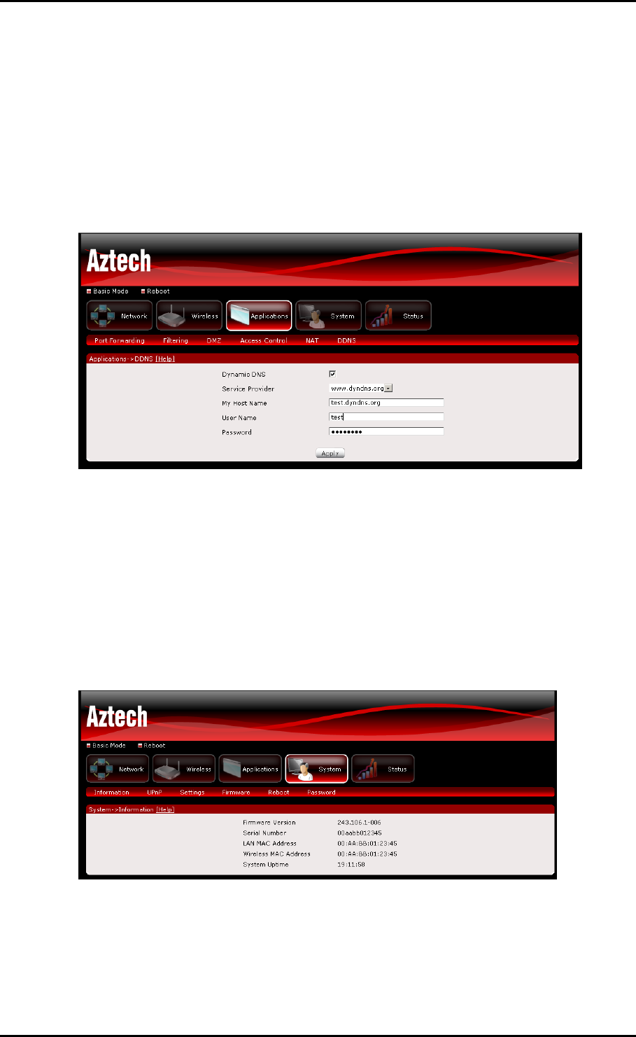
DDNS
The router offers a Dynamic Domain Name System (DDNS) feature. DDNS lets you assign
a fixed host and domain name to a dynamic Internet IP Address. It is useful when you
are hosting your own website, FTP server, or other server behind the router.
Before using this feature, you need to sign up for DDNS service providers.
User Manual
Page 33
of 41
Using DynDNS.org
Key in the following parameters:
Service provider
Service provider Service provider
Service provider Select www.DynDNS.org.
My Hostname
My Hostname My Hostname
My Hostname Enter the hostname.
DynDNS Settings
DynDNS Settings DynDNS Settings
DynDNS Settings Enter your dyndns.org Username and password.
System
Information
Includes hardware and software information of your device, and the current system date
and time.

User Manual
Page 34
of 41
UPnP
This page allows you to enable/disable UPnP feature on the modem-router.
Settings Restore
To import a previously saved configuration file from your PC and update the settings of
your router, click Browse to locate the romfile.cfg upgrade file. Then click the Restore
button.
Settings Backup
To backup the settings as a configuration file saved on your PC, click the Backup button.
Select the folder where you want to save the file and key in the file name under which
you want to save the settings. Default file name is romfile.cfg.
Restore Default
To restore your router to its factory default settings, click the Reset button. When
prompted, click OK.
User Manual
Page 35
of 41
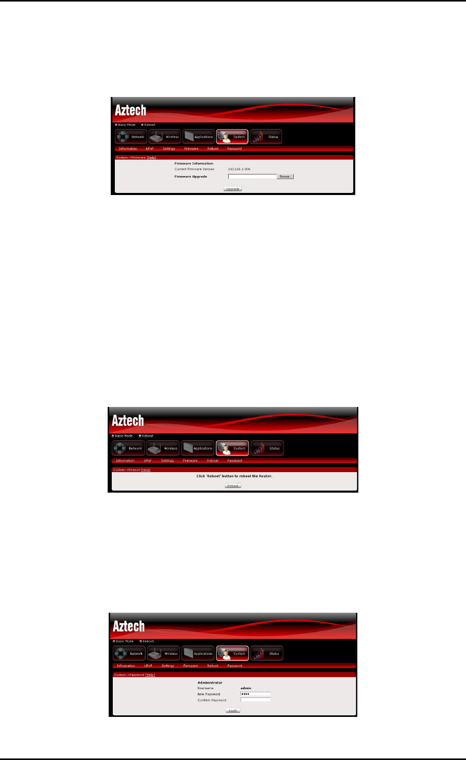
Firmware Upgrade
Allow you to update the firmware of your router.
To Update the router’s firmware:
1. Click Browse
2. Choose the firmware file and click OK
3. Click the Upgrade button
Reboot
This feature allows the router to enable new network configuration to take effect or to
clear problems with the router’s network connection.
Password Settings
Access to your DSL router is controlled through a login password. You may change the
default password on this page.
User Manual
Page 36
of 41
Status
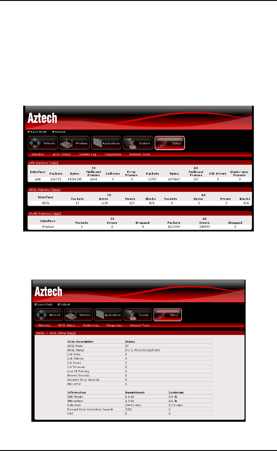
Device Statistics
The router will show you detailed statistical information regarding the different
connections on your router. This will include statistics for ADSL, WLAN and your Local Area
Network.
ADSL Status
The router shows detailed status information of its DSL connection.
User Manual
Page 37
of 41
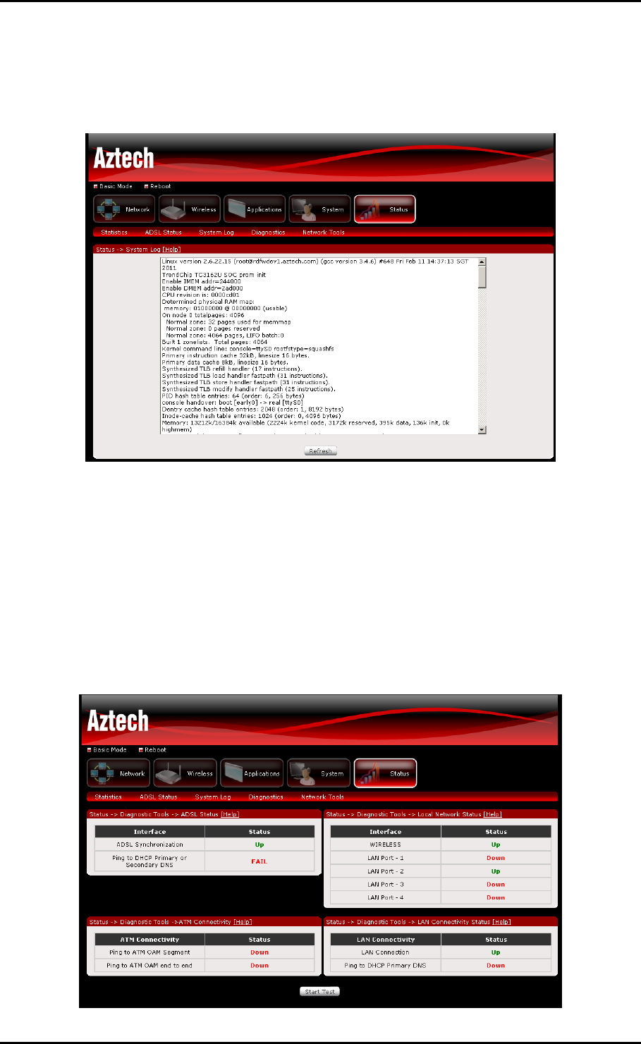
System Log
System log shows detailed information about the processes running in the router.
Diagnostics
Your modem is capable of testing your DSL connection. The individual tests are listed
below. If a test displays a fail status, click "Rerun Diagnostic Tests" at the bottom of this
page to make sure the fail status is consistent. If the test continues to fail, click "Help"
and follow the troubleshooting procedures.

User Manual
Page 38
of 41
Network Tools
Network tools will help you troubleshoot Internet connection problems by verifying your
connection.

User Manual
Page 39
of 41
Safety Precautions
Do not open, service, or change any component.
Only qualified technical specialists are allowed to service the equipment.
Observe safety precautions to avoid electric shock
Check voltage before connecting to the power supply. Connecting to the wrong
voltage will damage the equipment.

User Manual
Page 40
of 41
FCC Notice
This equipment has been tested and found to comply with the limits for a Class B digital device, pursuant
to Part 15 of the FCC Rules. These limits are designed to provide reasonable protection against harmful
interference in a residential installation. This equipment generates, uses, and can radiate radio frequency
energy and, if not installed and used in accordance with the instructions, may cause harmful interference
to radio communications. However, there is no guarantee that interference will not occur in a particular
installation. If this equipment does cause harmful interference to radio or television reception, which can
be determined by turning the equipment off and on, the user is encouraged to try to correct the
interference by one or more of the following measures:
• Reorient or relocate the receiving antenna.
• Increase the separation between the equipment and receiver.
• Connect the equipment into an outlet on a circuit different from that to which the receiver is
connected.
• Consult the dealer or an experienced radio or television technician for help.
Modifications
ModificationsModifications
Modifications
The FCC requires the user to be notified that any changes or modifications made to this device that are not
expressly approved by Aztech could void the user’s authority to operate the equipment.
This device complies with Part 15 of the FCC rules.
This device complies with Part 15 of the FCC rules.This device complies with Part 15 of the FCC rules.
This device complies with Part 15 of the FCC rules.
This device complies with Part 15 of the FCC rules. Operation is subject to the following two conditions:
1. This device may not cause harmful interference, and
2. This device must accept any interference received, including interference that may cause
undesired operation.
Exposure Information to Radio Frequency Energy
Exposure Information to Radio Frequency EnergyExposure Information to Radio Frequency Energy
Exposure Information to Radio Frequency Energy
This equipment complies with FCC radiation exposure limits set forth for an uncontrolled environment. This
equipment should be installed and operated with minimum distance of 20 cm between the radiator and
your body.
15.19:
This device complies with part 15 of the FCC Rules. Operation is subject to the following two conditions: (1)
this device does not cause harmful interference.(2)this device must accept any Interference received,
including interference that may cause undesired operation.
15.21:
Changes or modifications not expressly approved by the party responsible for compliance could void the
user's authority to operate the equipment.

User Manual
Page 41
of 41
Customer Information
Customer InformationCustomer Information
Customer Information
1. This equipment complies with Part 68 of the FCC rules and the requirements adopted by the ACTA.
On bottom of this equipment is a label that contains, among other information, a product identifier
of [US:4J2DL01BDSL5085EN]. If requested, this number must be provided to the telephone
company.
2. If this equipment [ADSL2+ 4-Ports 300Mbps Wireless-N Modem Router] causes harm to the
telephone network, the telephone company will notify you in advance that temporary
discontinuance of service may be required. But if advance notice isn’t practical, the telephone
company will notify the customer as soon as possible. Also, you will be advised of your right to file
a complaint with the FCC if you believe it is necessary.
3. The telephone company may make changes in this facilities, equipment, operations or procedures
that could affect the operation of the equipment. If this happens the telephone company will
provide advance notice in order for you to make necessary modification to maintain uninterrupted
service.
4. If you experience trouble with this equipment, you disconnect it from the network until the
problem has been corrected or until you are sure that the equipment is not malfunctioning.
5. Please follow instructions for repairing if any (e.g. battery replacement section); otherwise do not
alternate or repair any parts of device except specified.
6. Connection to party line service is subject to state tariffs. Contact the state public utility
commission public service commission or corporation commission for information.
7. If the telephone company requests information on what equipment is connected to their lines,
inform them of:
a. The telephone number that this unit is connected to,
b. The ringer equivalence number [0.1B]
c. The USOC jack required [RJ11C], and
d. The FCC Registration Number [US:4J2DL01BDSL5008EN]
Items (b) and (d) are indicated on the label. The ringer equivalence number (REN) is used to
determine how many devices can be connected to your telephone line. In most areas, the
sum of the RENs of all devices on any one line should not exceed five (5.0). If too many
devices are attached, they may not ring properly.
Service Requirements
Service RequirementsService Requirements
Service Requirements
In the event of equipment malfunction, all repairs should be performed by our Company or an authorized
agent. It is the responsibility of users requiring service to report the need for service to our Company or to
one of our authorized agents. Service can be facilitated through our office at:
Aztech Labs Inc
Aztech Labs IncAztech Labs Inc
Aztech Labs Inc
4005, Clipper Court, Fremont, CA, 94538.