AzureWave Technologies 800BT 802.11b/g USB WLAN Module User Manual AW GA800BT
AzureWave Technologies, Inc. 802.11b/g USB WLAN Module AW GA800BT
UserManual.wiki
>
AzureWave Technologies
>
800BT User Manual
Manual
Navigation menu
Upload a User Manual
Namespaces
Wiki Guide
HTML
PDF
Info
Views
User Manual
Discussion / Help
Navigation
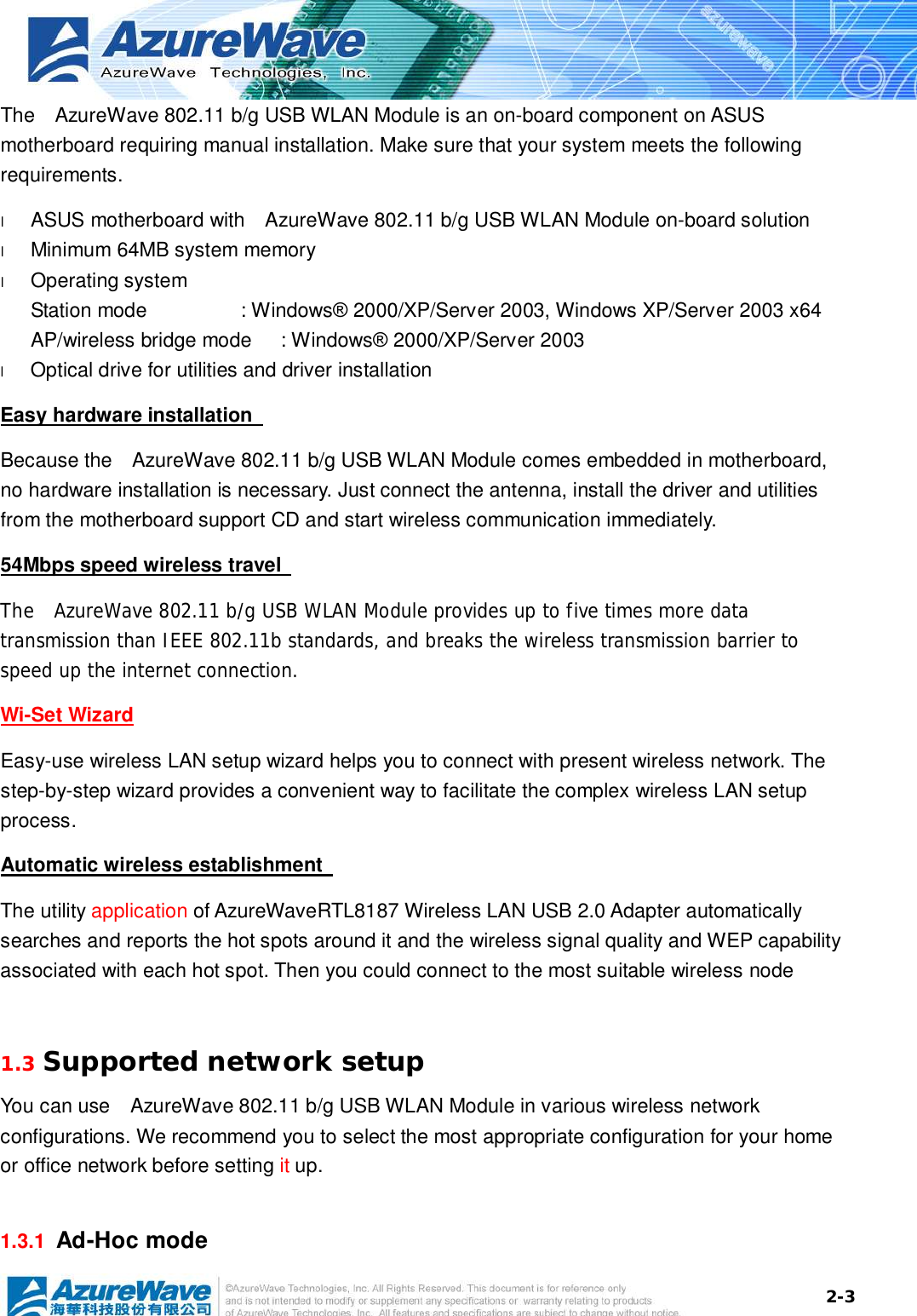
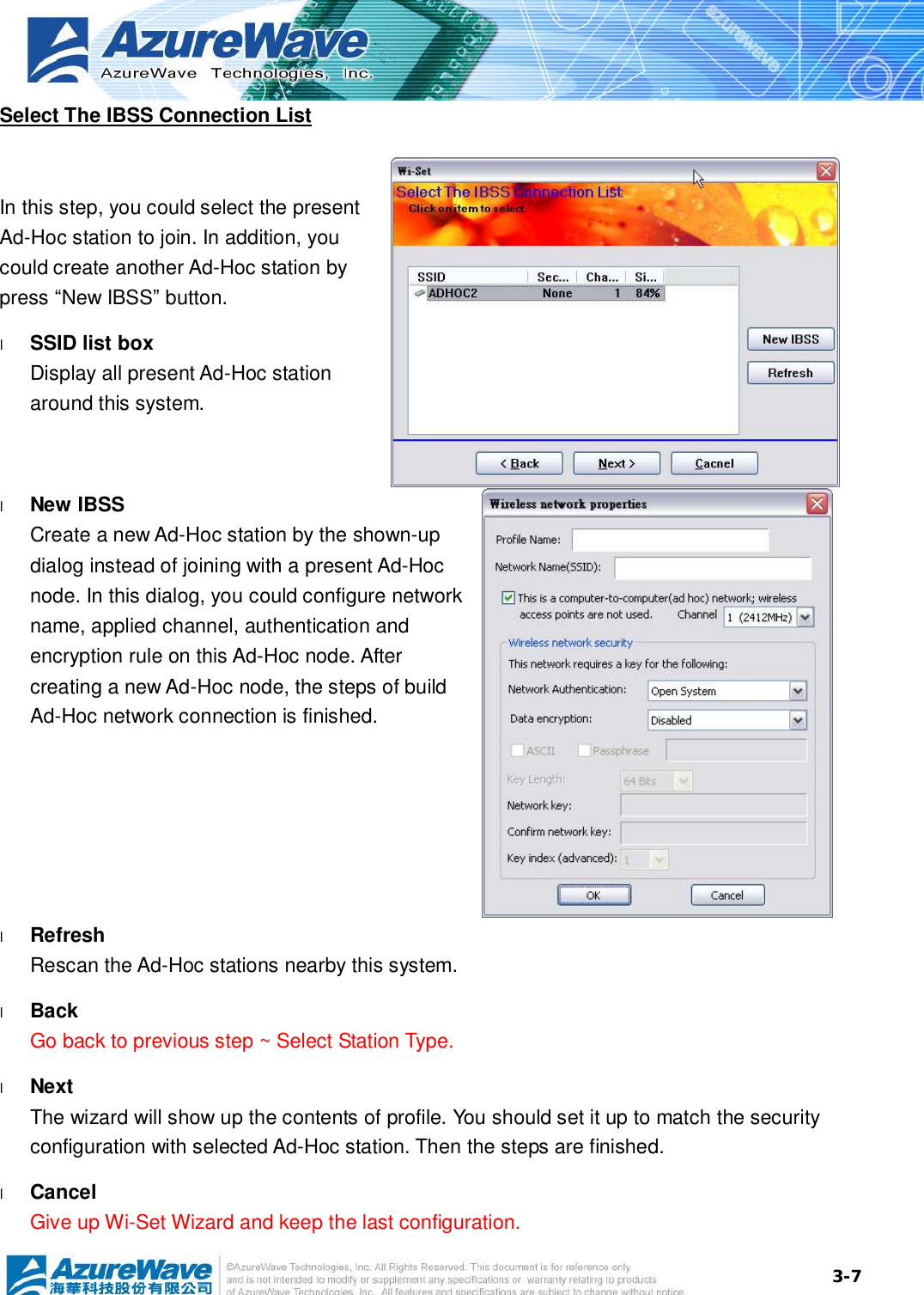
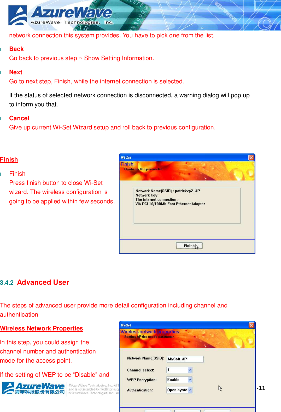

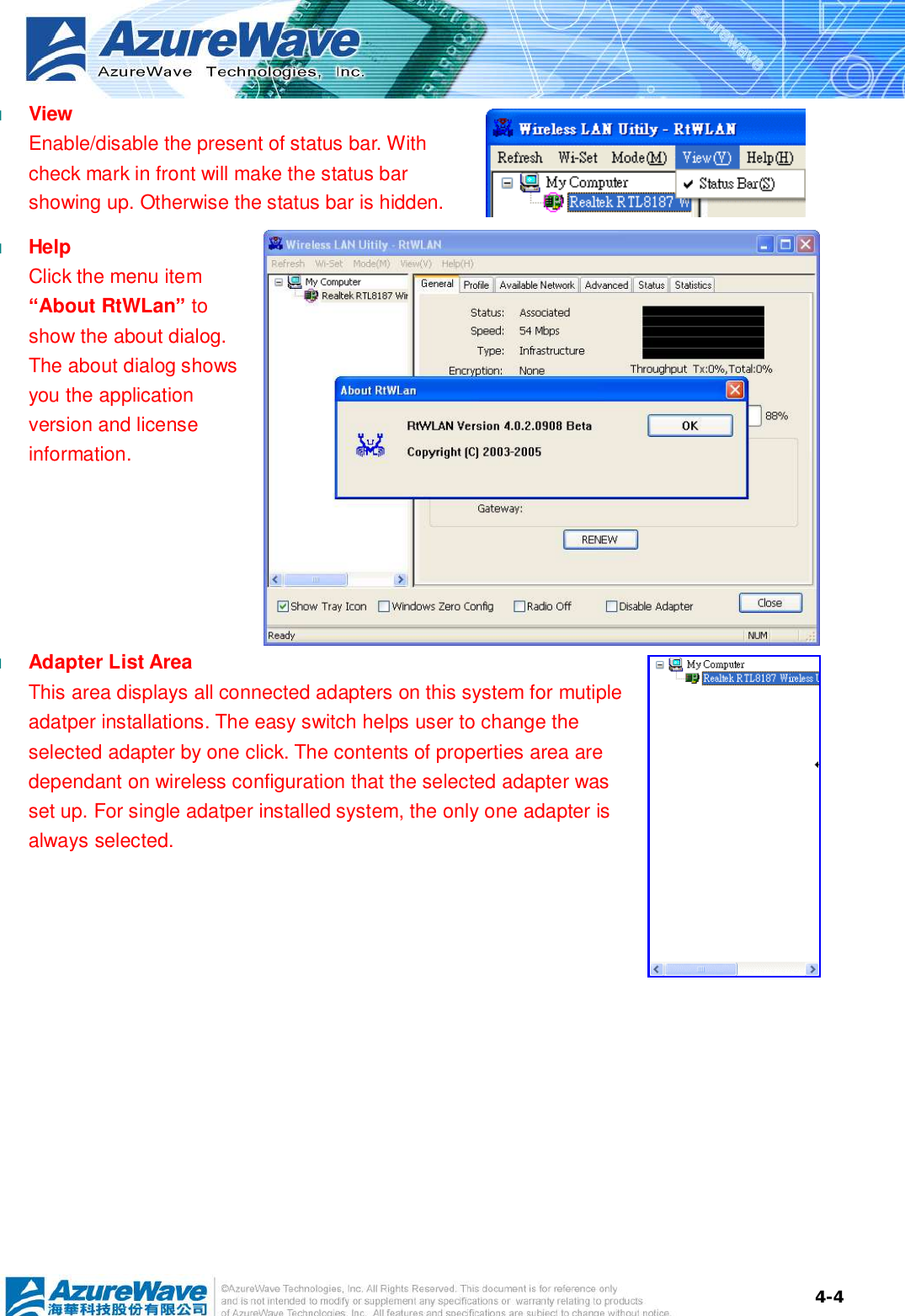
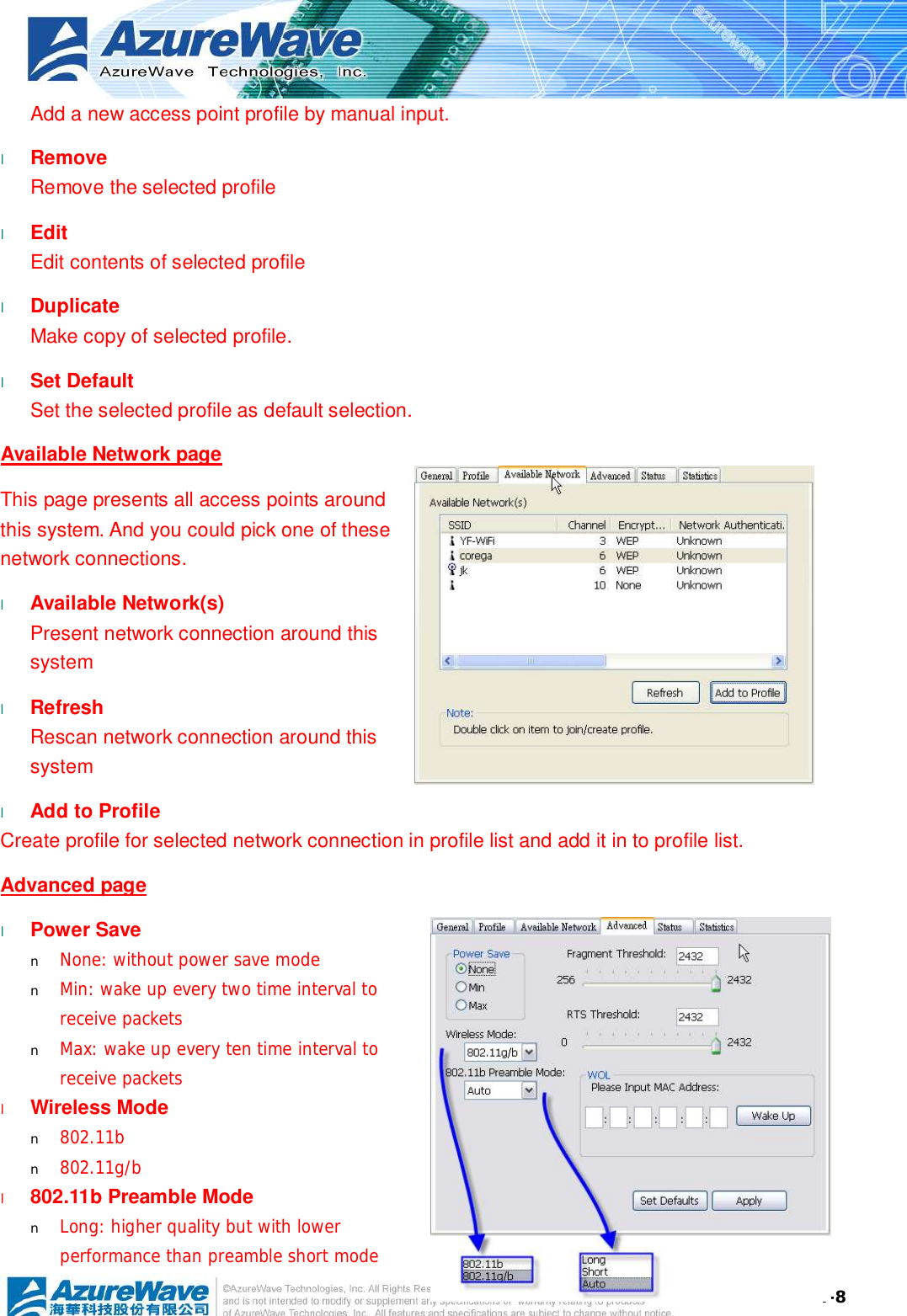
![4-3 Main Menu The main menu includes five submenus. l Refresh As clicking the refresh menu, the contents of adapter list area are re-enumerated and updated. l Wi-Set Quickly launching the Wi-Set Wizard. The convenient quick launching helps you to reprogram the wireless configuration as need. l Mode Quickly switching wireless configuration to be either [Station] or [Access Point]. The item with check mark in front is the current wireless configuration.](https://usermanual.wiki/AzureWave-Technologies/800BT/User-Guide-655639-Page-26.png)