AzureWave Technologies AWNU231 Wireless 802.11 a/b/g/n Module User Manual AW NU231
AzureWave Technologies, Inc. Wireless 802.11 a/b/g/n Module AW NU231
User Manual

User Manual
Wireless 802.11 a/b/g/n Module
Chapter 1: Product Overview
AzureWave Technologies, Inc. introduces the advanced IEEE 802.11a/b/g/n
2x2 dual-band WLAN USB 2.0 module - AW-NU231. The module
supports both 2.4GHz and 5GHz bands and Multiple Input Multiple Output (MIMO)
technology. With MIMO, information is simultaneously sent and received over two
antennas in the same frequency band, thus providing greater range and
increased throughput while maintaining compatibility with legacy IEEE
802.11a/b/g devices. By using AW-NU231, the customers can easily enable the
development of USB 2.0-based Draft-802.11n WLAN client and router subsystem
solutions for all WLAN markets that can take advantage of the high throughput
and extended range of MIMO.
In Compliance with the IEEE 802.11a/b/g/n standard, the AW-NU231 uses Direct
Sequence Spread Spectrum (DSSS), orthogonal frequency division multiplexing
(OFDM), DBPSK, DQPSK, CCK and QAM baseband modulation technologies. A
high level of integration and full implementation of the power management
functions specified in the IEEE 802.11 standard minimize the system power
requirements. By using AW-NU231, state-of-the-art security is provided by
industry standard system support for WPA, WPA2, and hardware accelerated
AES encryption/decryption coupled with TKIP and IEEE 802.1X support.
Embedded hardware acceleration enhances system performance and
significantly reduces host-CPU utilization in both client and access point
configurations. The AW-NU231 also supports Broadcom’s widely accepted and
deployed SecureEasySetup™ (SES) application for ease-of-use wireless
secured networks.
The AW-NU231 module adopts Broadcom’s latest Draft-802.11n-based chip,
BCM4323, innovations designed to increase WLAN system performance and
extend range using MIMO technology. The module integrates two dual-band
antennas which are used for 2x2 MIMO and supports 2-stream spatial
multiplexing up to 300Mbps.
Chapter 2: Installation
This chapter describes the procedure for installing the NU231
To install the module:
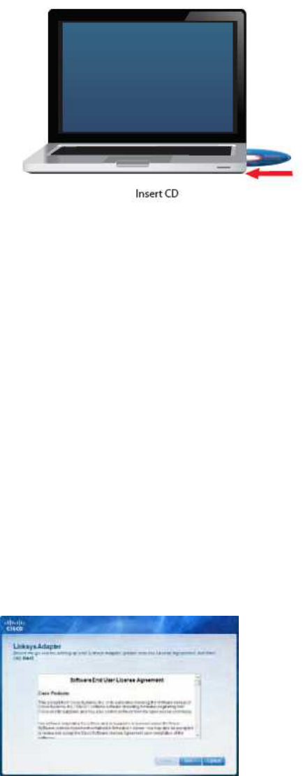
1 Insert the CD into your CD-ROM drive
2 Click Set up your NU231
If you do not see this, access setup on the CD directly To do so, perform the following steps for
your specific operating system:
Windows 7
a Go to Start > Computer
b Double-click your CD-ROM drive
Windows Vista
a Go to Start > Computer
b Double-click your CD-ROM drive
Windows XP
a Go to Start > My Computer and select your CD-ROM drive
b Double-click Setup.exe
3 Read the Software End User License Agreement To accept the agreement and
continue with the installation, click Next
License Agreement
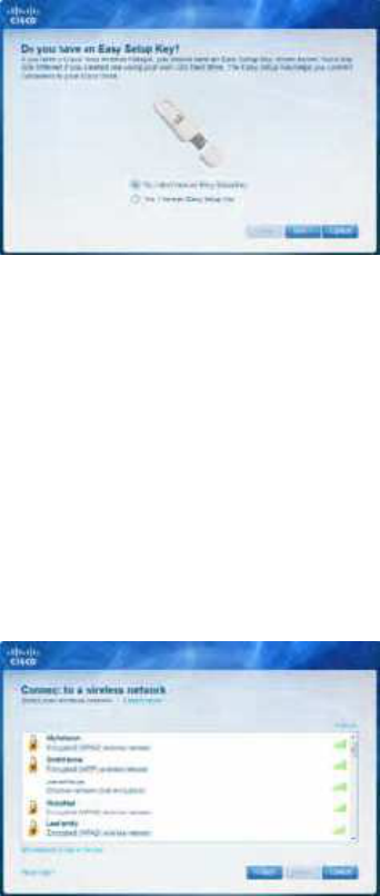
4 An Easy Setup Key helps you quickly connect to your wireless hotspot or router
If you do not have an Easy Setup Key, select No, I don¡¦t have an Easy Setup Key
If you have an Easy Setup Key, select Yes, I have an Easy Setup Key Click Next
NOTE: Cisco Valet wireless hotspots come with
an Easy Setup Key Cisco Valet wireless hotspots
and some Linksys routers also let you create one
from your own USB flash drive ( You do not need
an Easy Setup Key to complete installation )
Do You Have an Easy Setup Key?
If you do not have an Easy Setup Key, go to step 6
If you have an Easy Setup Key, go to step 8
6 A list of available wireless networks appears Select your network Click Next
Connect to a Wireless Network
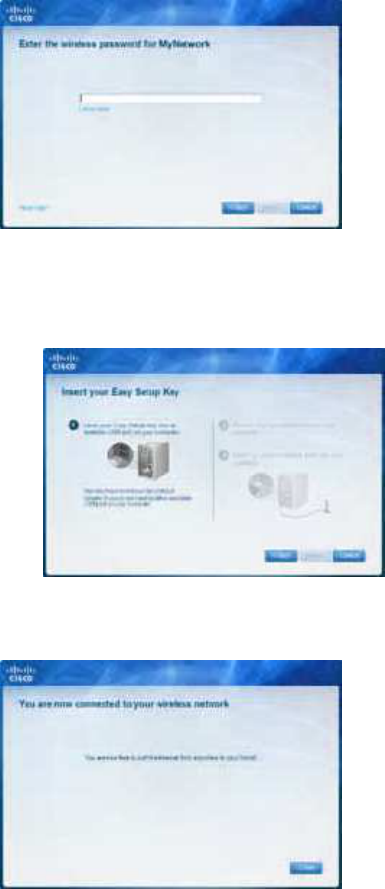
7 If your network does not use wireless security, go to step 9
If your network uses wireless security, enter the wireless password for your type of
security:
¡E Wired Equivalent Privacy (WEP): Enter the WEP key
¡E Wi-Fi Protected Access ( WPA/WPA2): Enter the
passphrase (also known as a pre-shared key) Click
Next Go to step 9
Enter the Wireless Password
8 Follow the on-screen prompts to use your Easy Setup Key Click Next
Insert your Easy Setup Key
9 The installation is complete Click Close
You are Now Connected to Your Wireless Network
NOTE: If you have any problems during the installation process, refer to
the Frequently Asked Questions in the setup software

Chapter 3: Wireless Network
Configuration
To configure the module ¡¦s wireless connection settings, use a wireless network installed
such a utility on your computer, or if your configuration utility If you have computer
came with one already installed, refer to that utility¡¦s documentation for instructions on use
Otherwise, follow the instructions in the appropriate section below to use your operating
system¡¦s built-in utility: Windows 7,
Windows 7
After you have installed the module, the Wireless Network Configuration utility icon appears
on your computer¡¦s system tray
Wireless Network Configuration Utility Icon
(If you do not see the icon, click the Show hidden icons arrow in the system tray )
When your mouse pointer hovers over the icon, the status information of your wireless connection
appears
Wireless Connection Status
New Wireless Connection
To connect to a different wireless network:
1 Click the Wireless Network Configuration utility icon. A list of available wireless networks
appears
After you have installed the module, the Wireless Network
Configuration utility icon appears on your computer¡¦s
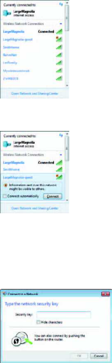
Available Wireless Networks
2 Select your network, and then click Connect
Select Network
3 If your network does not use wireless security, go to step 5
4 Enter the security key, Wired Equivalent Privacy (WEP) key, or Wi-Fi Protected Access
(WPA/WPA2) passphrase (also known as a pre-shared key), depending on your type of security
Click OK
Secured Network
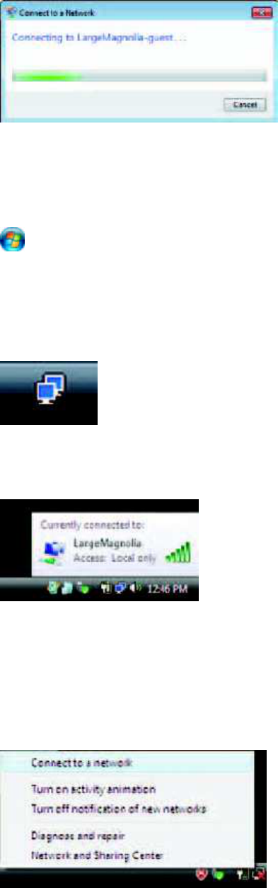
5 This screen appears while the module connects to your network Do not cancel,
unless you want to end the connection
Connecting to Network
NOTE: For help with the Wireless Network Configuration utility, refer to Help and
Support Click Start > Help and Support
Your computer is now connected to your wireless network.
Windows Vista
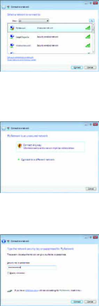
After you have installed the module, the Wireless Network Configuration utility icon appears
on your computer¡¦s system tray
Wireless Network Configuration Utility Icon
When your mouse pointer hovers over the icon, the status information of your wireless connection
appears
Wireless Connection Status
New Wireless Connection
To connect to a different wireless network:
1 Right-click the Wireless Network Configuration utility icon
2 Click Connect to a network
Utility Menu
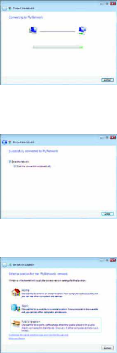
3 Select your network, and then click Connect
Select Network
4 If your network uses wireless security, go to step 5
If your network does not use wireless security, this screen appears To connect to your
unsecured network, click Connect Anyway and go to step 7
Unsecured Network
5 Enter the security key, Wired Equivalent Privacy (WEP) key, or Wi-Fi Protected Access
(WPA/WPA2) passphrase (also known as a pre-shared key), depending on your type of security
Click Connect
Secured Network
6 This screen appears while the module connects to your network Do not cancel,
unless you want to end the installation
Connecting to Network
7 This screen appears when you are connected to your network Select Save this network, if you
want to save your settings Click Close
Connected to Network
8 The Set Network Location screen may appear This screen helps apply the correct
settings for your type of location Select Home, Work, or Public location
Select Network Location
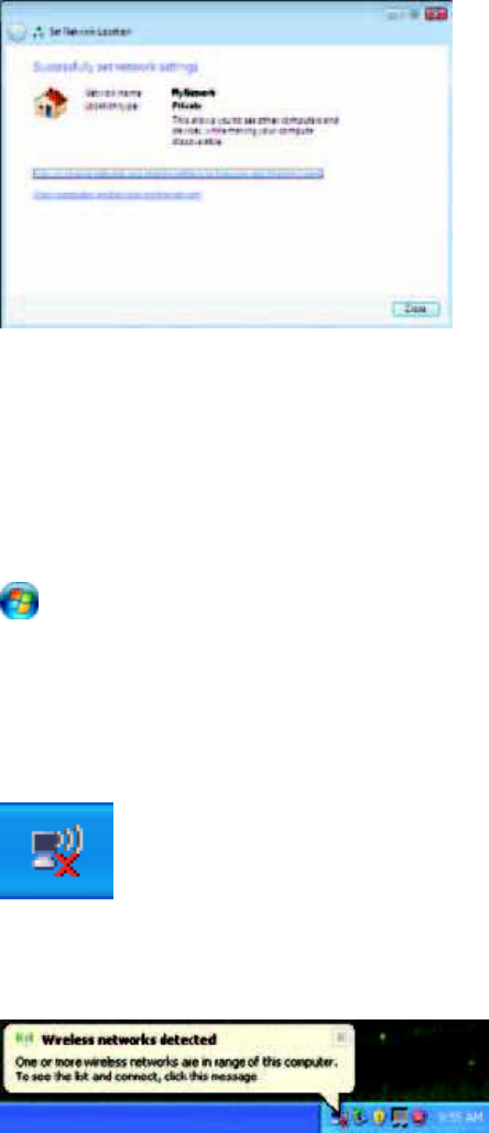
9 This screen varies according to the selected location Click Close
Network Settings Saved
NOTE: For help with the Wireless Network Configuration utility, refer to Help and
Support Click Start > Help and Support
Your computer is now connected to your wireless network.
Windows XP
After you have installed the module, the Windows XP Wireless Zero Configuration
Utility icon appears on your computer¡¦s system tray
Wireless Zero Configuration Utility Icon
When your mouse pointer hovers over the icon, the status information of your wireless connection
appears
New Wireless Connection
1 Right-click the Windows XP Wireless Zero Configuration icon in your computer¡¦s
system tray, and then select View Available Wireless Networks
2 A window displays the available wireless networks continue to Select the network
that you want and click Connect If the network uses wireless security, go to step 4
Otherwise, continue to step 3
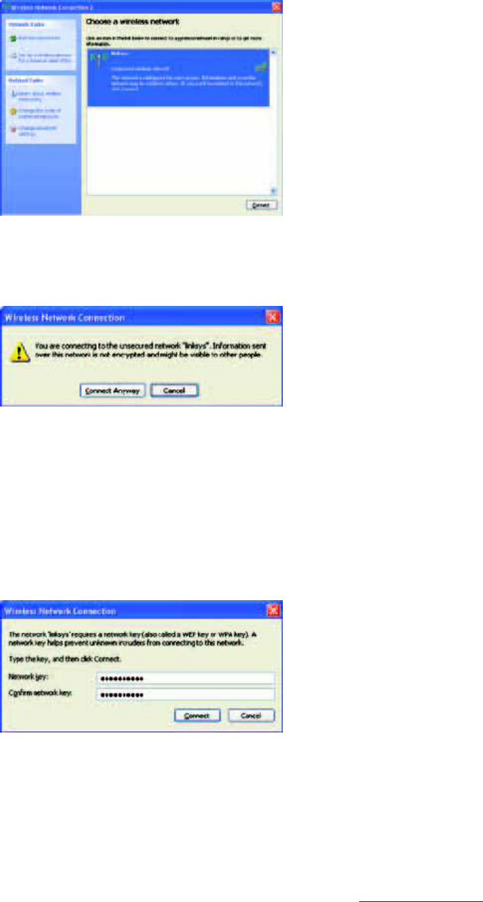
Available Wireless Network
3 Click Connect Anyway to connect the module to your unsecured network, and then go to step
5
No Wireless Security
4 If your network uses Wired Equivalent Privacy (WEP) wireless security, enter the WEP Key
in the Network key and Confirm network key fields If your network uses Wi-Fi Protected
Access (WPA/WPA2) wireless security, enter the passphrase in the Network key and Confirm
network key fields Click Connect
Wireless Security
NOTE: Windows XP Wireless Zero Configuration does not support the use of a WEP
passphrase Enter the exact WEP key used by your wireless router or access point
NOTE: If your network is using WPA2 security, make sure that you have installed the
Update for Windows XP (KB893357), available at www.microsoft.com
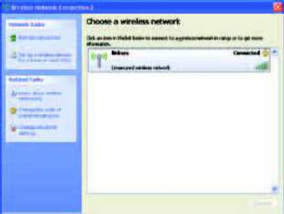
5 Your wireless network will appear as Connected when your connection is active
Wireless Network Connection
NOTE: For help with the Wireless Network Configuration utility, refer to Help and
Support Click Start > Help and Support Enter wireless in the Search field, and then press
Enter
Your computer is now connected to your wireless network.
Federal Communication Commission Interference Statement
This equipment has been tested and found to comply with the limits for a Class B digital
device, pursuant to Part 15 of the FCC Rules. These limits are designed to provide
reasonable protection against harmful interference in a residential installation. This
equipment generates, uses and can radiate radio frequency energy and, if not installed
and used in accordance with the instructions, may cause harmful interference to radio
communications. However, there is no guarantee that interference will not occur in a
particular installation. If this equipment does cause harmful interference to radio or
television reception, which can be determined by turning the equipment off and on, the
user is encouraged to try to correct the interference by one of the following measures:
- Reorient or relocate the receiving antenna.
- Increase the separation between the equipment and receiver.
- Connect the equipment into an outlet on a circuit different from that
to which the receiver is connected.
- Consult the dealer or an experienced radio/TV technician for help.
FCC Caution: Any changes or modifications not expressly approved by the party
responsible for compliance could void the user's authority to operate this equipment.
This device complies with Part 15 of the FCC Rules. Operation is subject to the following
two conditions: (1) This device may not cause harmful interference, and (2) this device
must accept any interference received, including interference that may cause undesired
operation.
For operation within 5.15 ~ 5.25GHz frequency range, it is restricted to indoor
environment.
IMPORTANT NOTE:
FCC Radiation Exposure Statement:
This equipment complies with FCC radiation exposure limits set forth for an uncontrolled
environment. This equipment should be installed and operated with minimum distance
20cm between the radiator & your body. This transmitter must not be co-located or
operating in conjunction with any other antenna or transmitter.

This device is intended only for OEM integrators under the following
conditions:
1) The antenna must be installed such that 20 cm is maintained between the antenna
and users, and
2) The transmitter module may not be co-located with any other transmitter or antenna,
3) For all products market in US, OEM has to limit the operation channels in CH1 to
CH11 for 2.4G band by supplied firmware programming tool. OEM shall not supply
any tool or info to the end-user regarding to Regulatory Domain change.
As long as 3 conditions above are met, further transmitter test will not be required.
However, the OEM integrator is still responsible for testing their end-product for any
additional compliance requirements required with this module installed.
IMPORTANT NOTE: In the event that these conditions can not be met (for example
certain laptop configurations or co-location with another transmitter), then the FCC
authorization is no longer considered valid and the FCC ID can not be used on the final
product. In these circumstances, the OEM integrator will be responsible for re-evaluating
the end product (including the transmitter) and obtaining a separate FCC authorization.
End Product Labeling
This transmitter module is authorized only for use in device where the antenna may be
installed such that 20 cm may be maintained between the antenna and users. The final
end product must be labeled in a visible area with the following: “Contains FCC ID:
TLZ-AWNU231”.
Manual Information To the End User
The OEM integrator has to be aware not to provide information to the end user regarding
how to install or remove this RF module in the user’s manual of the end product which
integrates this module.
The end user manual shall include all required regulatory information/warning as show in
this manual.