AzureWave Technologies BT715C Bluetooth Module User Manual 1292 user guide
AzureWave Technologies, Inc. Bluetooth Module 1292 user guide
User Manual_rev.pdf

- 1 -
AW-BT715C
Bluetooth Module
Demo Board User Guide
Version 0.1
- 2 -
Document
release Date Modification Initials Approved
Version 0.1 2014/06/26 Initial Version N.C. Chen Chihhao Liao
- 3 -
Contents
1. Install driver and tool
install active perl version: 5.8.4.810 before install Broadcom tool
install Broadcom tool BLUETOOL version:1.7.3.3
install CP210X(USB to UART ) driver CP210X_VCP_Win2K_XP_S2K3
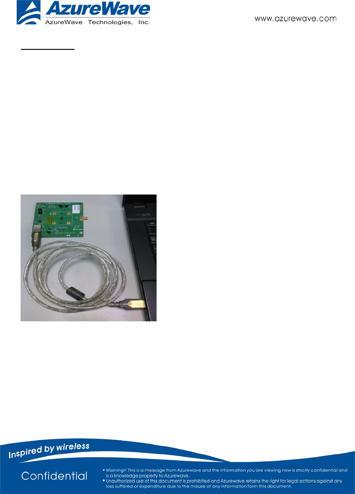
2. Connect the EVB to a PC
Use the cable to connect EVB with PC
- 4 -
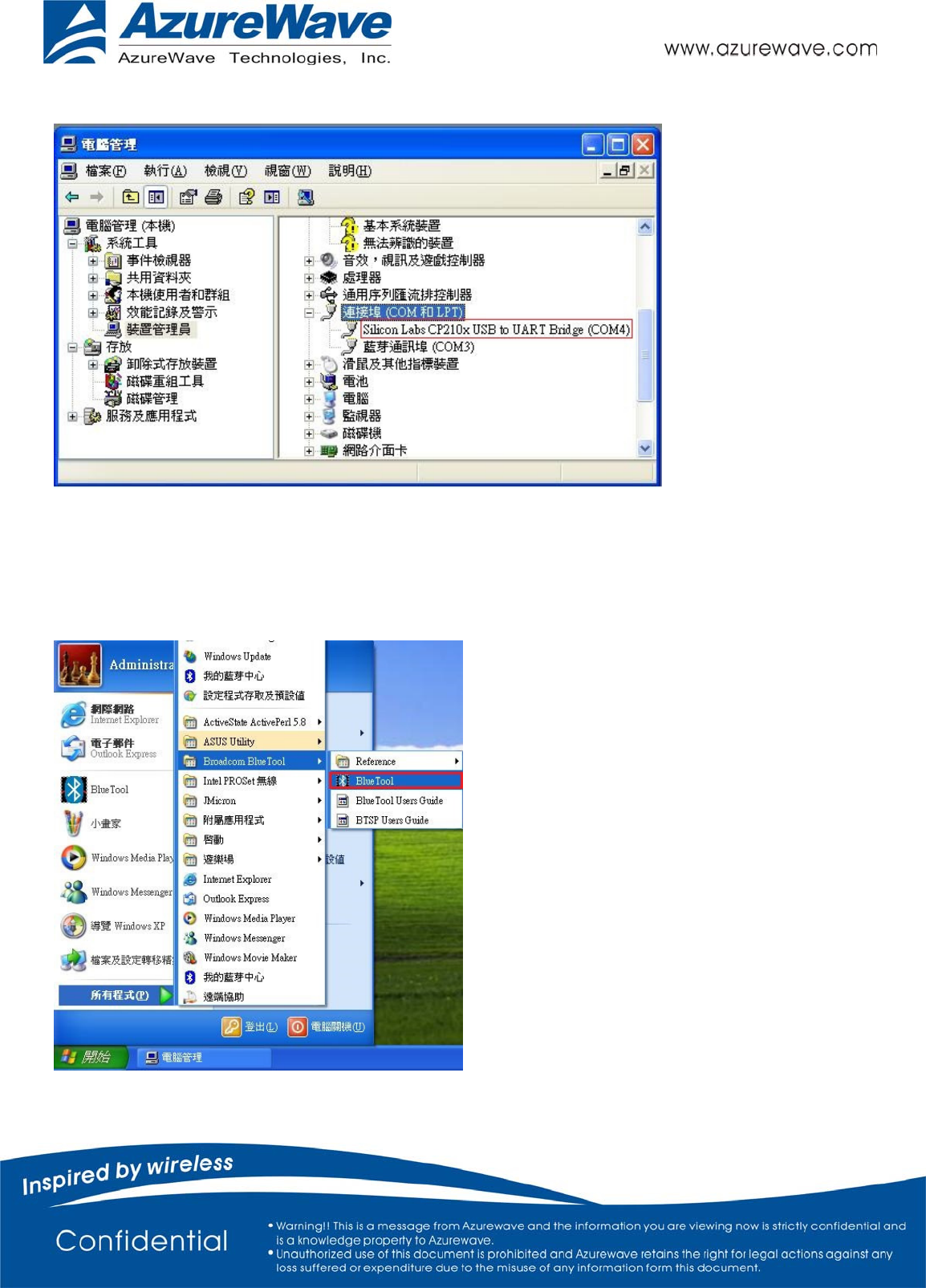
Check the com port that will be used.
A.CONNECT TO A BLUETOOTH TESTER
Run BlueTool, and then:
- 5 -
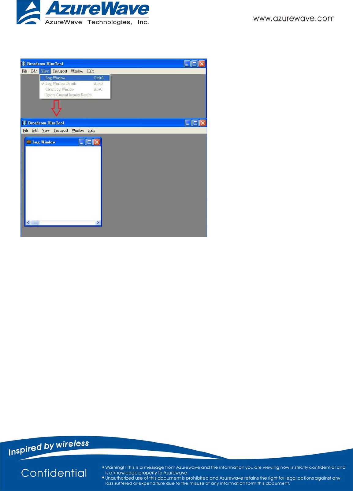
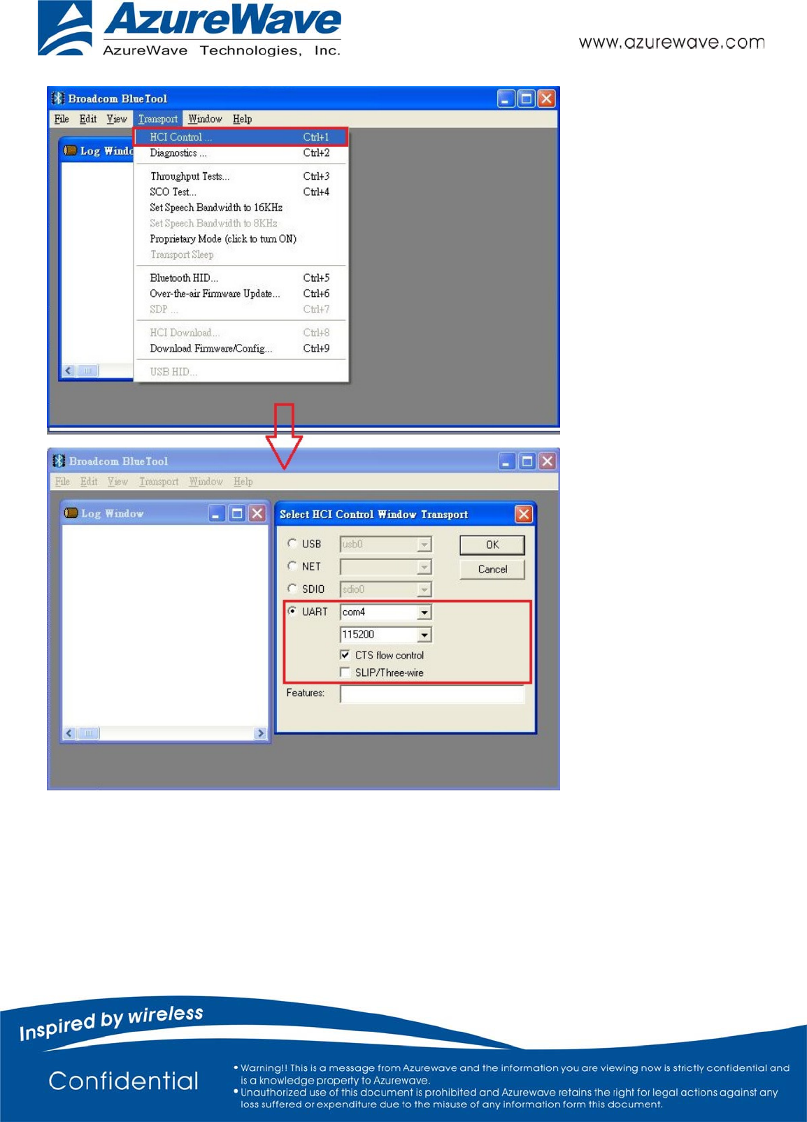
1. From the BlueTool View menu, select Log Window. A record of issued commands will be maintained in
the log window.
2. From the Transport menu, select HCI Control.
a. In the Select HCI Control Window Transport window (screenshot below), select UART, the COM port that
will be used, 115200, and CTS flow control.
b. Click OK.
- 6 -
- 7 -
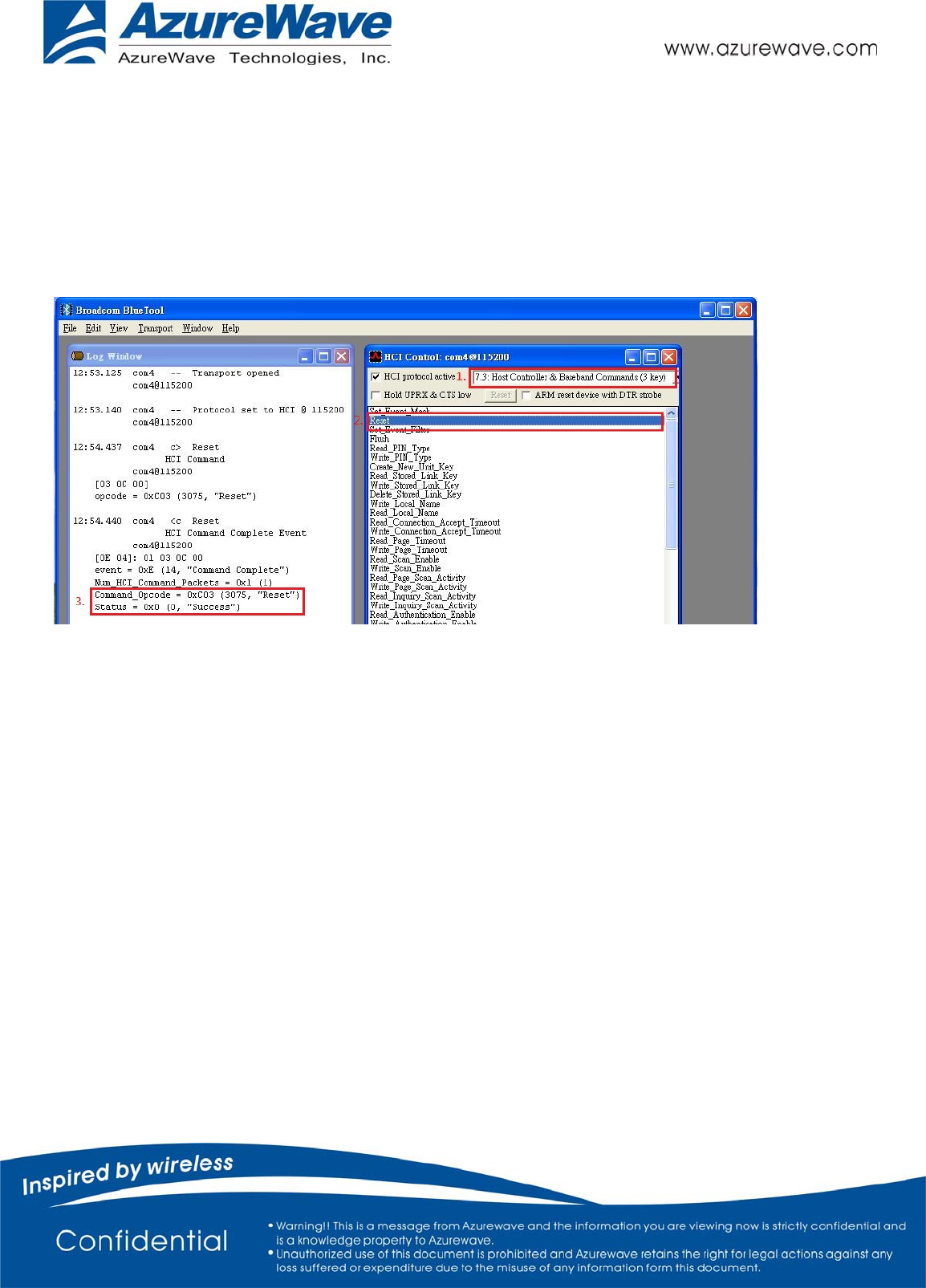
B. Reset
1.In the HCI Control window
a. Select 7.3 Host Controller & Baseband Commands (3 key) for HCI protocol active
b.Double-click Reset.
2. Confirm that this step is done successfully by viewing the log window
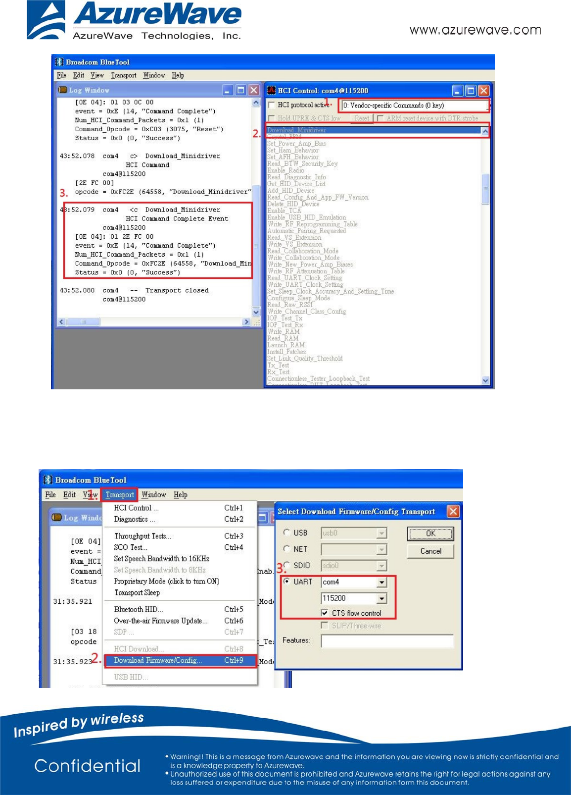
C. Download the Configuration File
1. In the HCI Control window
a. Select 0: Vendor-specific Commands (0 key) for HCI protocol active
b.Double-click Download Minidriver.
2. Confirm that this step is done successfully by viewing the log window
- 8 -
3. From the BlueTool Transport menu, select Download Firmware/Config….
4. In the Select Download Firmware/Config Transport window
a. select UART, the COM port that will be used, 115200,and CTS flow control.
b. Click OK.
- 9 -
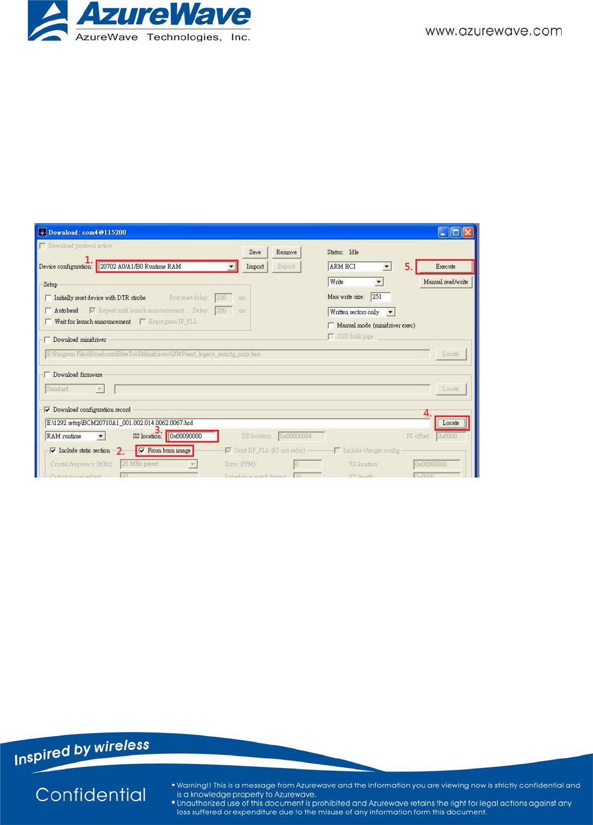
5. In the Download: com @115200 window,
a. select 20702 A0/A1/B0 Runtime RAM for Device configuration
b. mark From burn image
c. key in 0x00090000 on SS location
d. click Locate
e. select the configuration
f. click open
g. click Execute
h. close the window
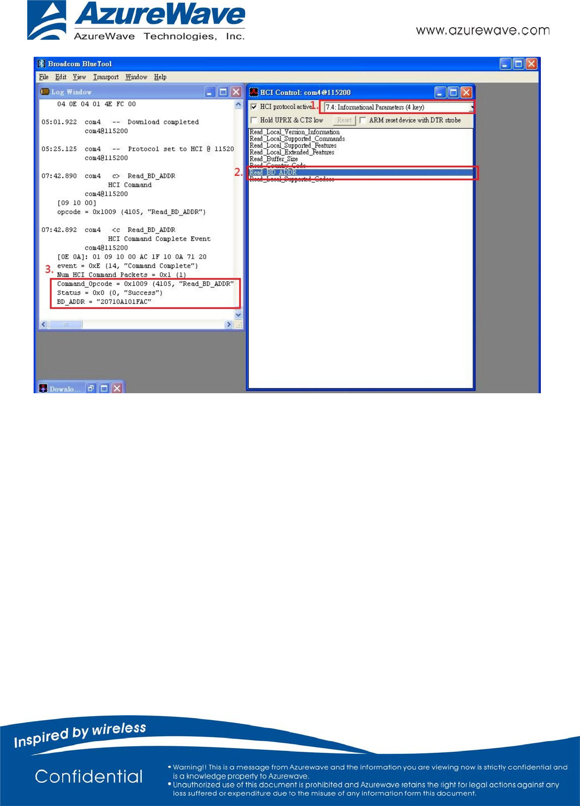
D. Verify the DUT condition by reading the BD address
1. In the HCI Control window
a. mark HCI protocol active ,select 7.4 Informational Parameters(4 keys)from it
b. Double-click Read BD ADDR.
2. The Log Window will show the BD address.
- 10 -
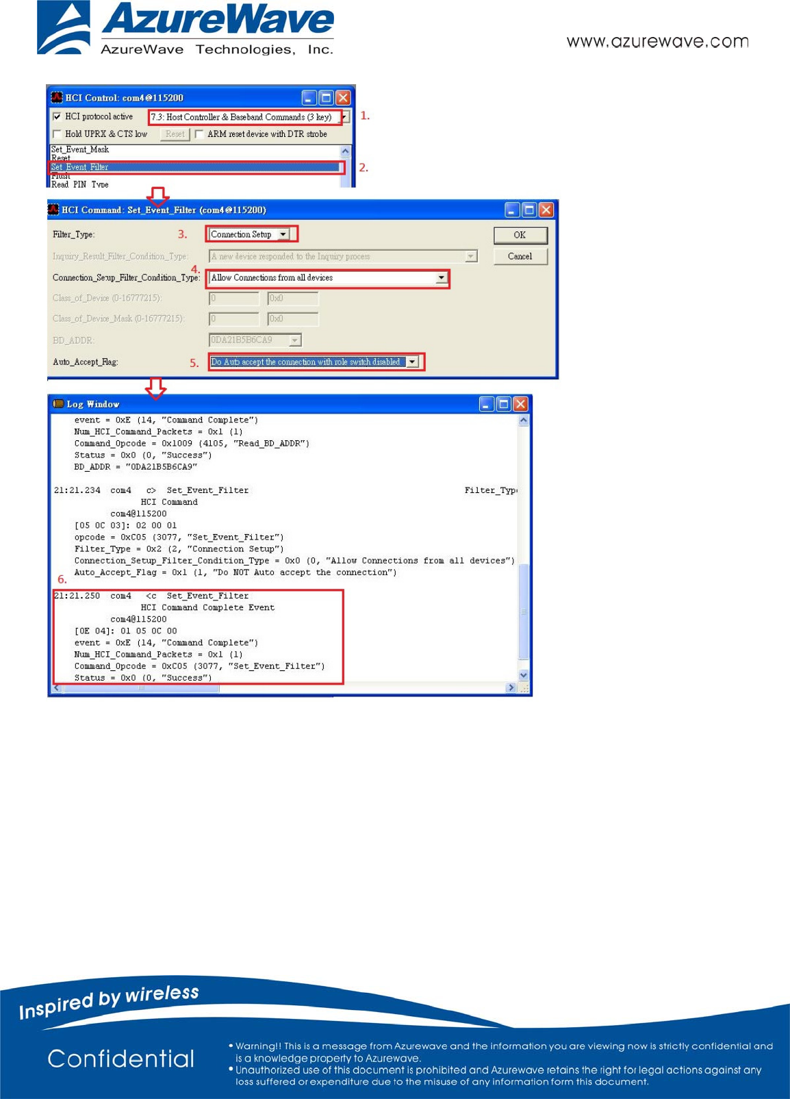
E. Set Event Filter
1. In the HCI Control window
a. select 7.3 Host Controller & Baseband Commands (3 key) for HCI protocol active
b. Double-click Set Event Filter.
2.In the HCI Command window
a. select connection setup for filter type
b. select Allow Connecttion from all devices for Connection_Setup_ Filter _Condition_type
c. select Do Auto accept the connection with role switch disabled for Auto_Accept_Flag
d. Click OK.
3. Confirm that this step is done successfully by viewing the log window .
- 11 -
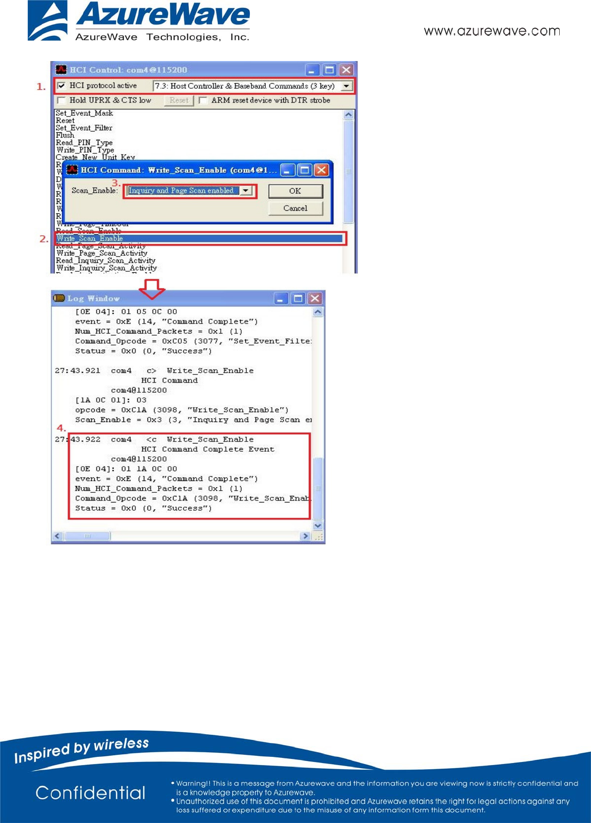
F. Write Scan Enable
1. In the HCI Control window
a. select 7.3 Host Controller & Baseband Commands (3 key) for HCI protocol active
b. Double-click. Write Scan Enable
2. In the HCI Command window
a. select Inquiry and Page Scan enabled for scan_Enable
b. Click OK.
3. Confirm that this step is done successfully by viewing the log window .
- 12 -
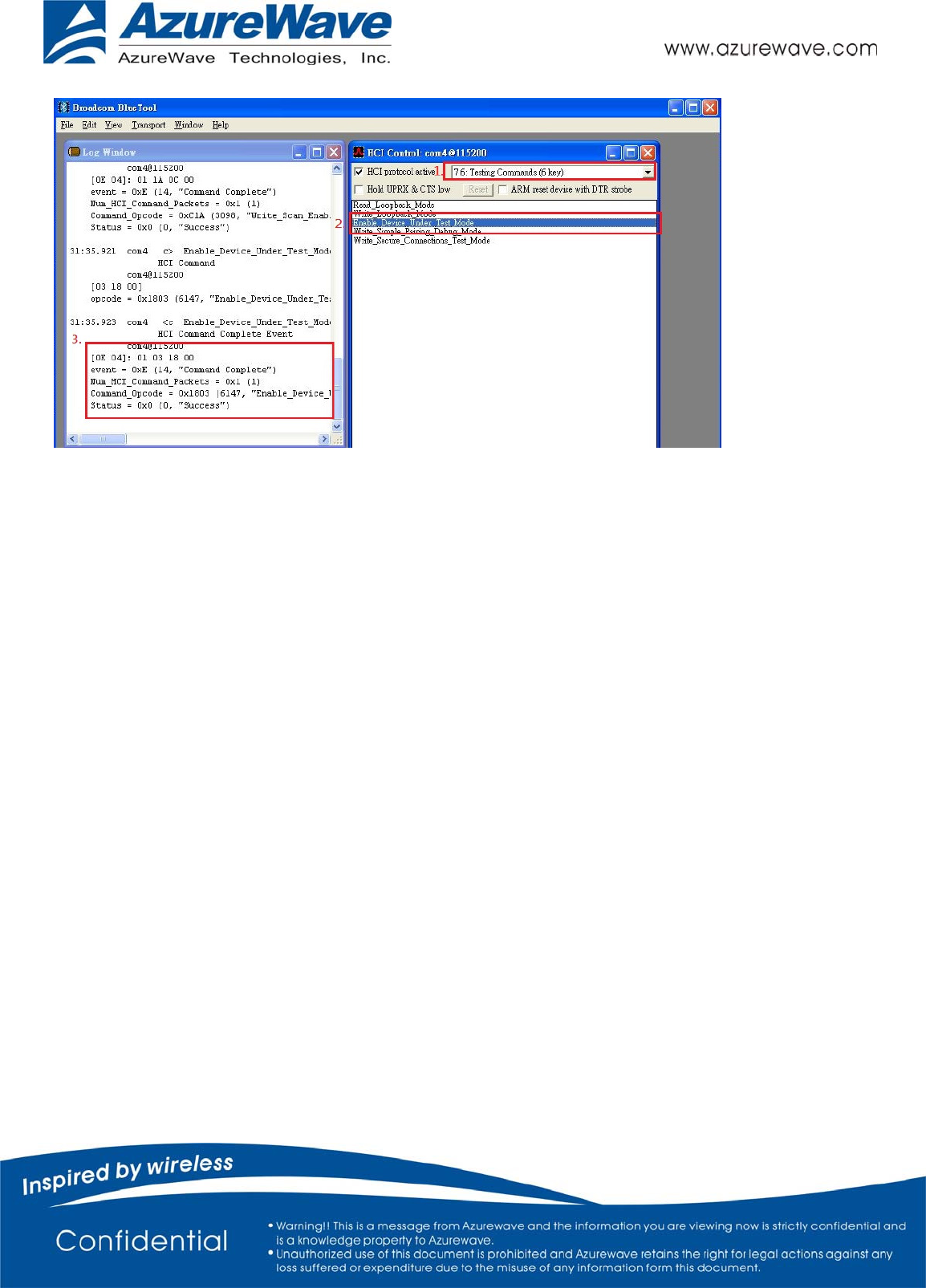
G. Enable Device Under Test Mode
1. In the HCI Control window
a. select 7.6 Testing Commands (6 key) for HCI protocol active
b. Double-click Enable Device Under Test Mode
2. Confirm that this step is done successfully by viewing the log window .
- 13 -
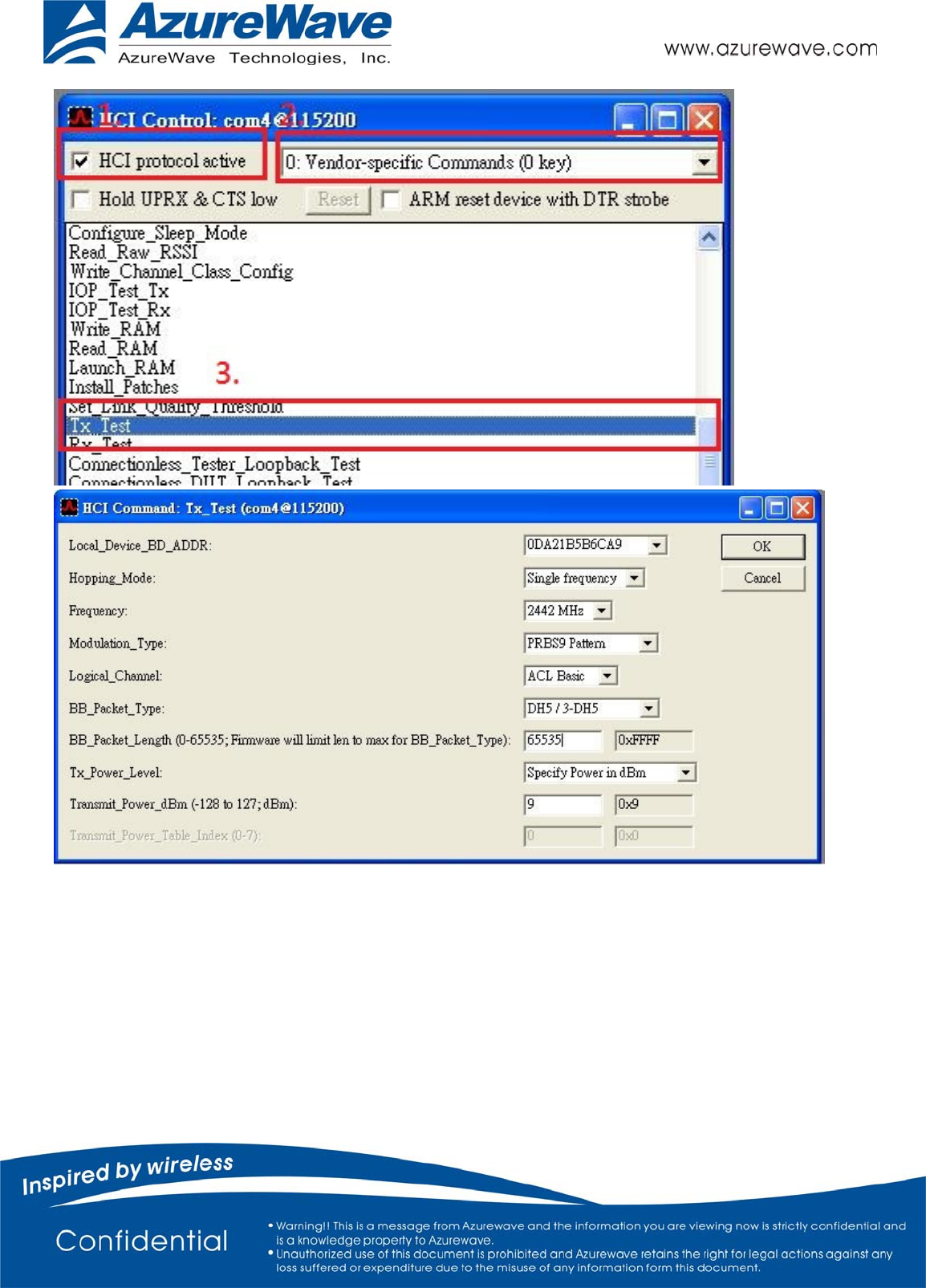
H.TX Testing
1. In the HCI Control window
a. select 0: Vendor-specific Commands (0 key) for HCI protocol active
b. Double-click TX Test
2. In the HCI command window
a. From the Local_Device_BD_ADDR shortcut menu, select the Bluetooth device address of the DUT.
b. From the Hopping_Mode shortcut menu, select single frequency.
c. From the frequency shortcut menu, select which frequency you want to test.
d. From the Modulation_Type shortcut menu, select PRBS9 Pattern.
e. From the Logical_Channel shortcut menu, select ACL Basic.
f. From the BB_Packet_Type shortcut menu, DH5/3-DH5, DH3/3-DH3, or DH1/2-DH1.
g. From the BB_Packet_length(….) shortcut menu, key 65535
h. From the Tx Power Level shortcut menu, select Specify Power in dBm
i. From the Transmit Power dBm shortcut menu, key in which power you want to transmit.
j. Click OK.
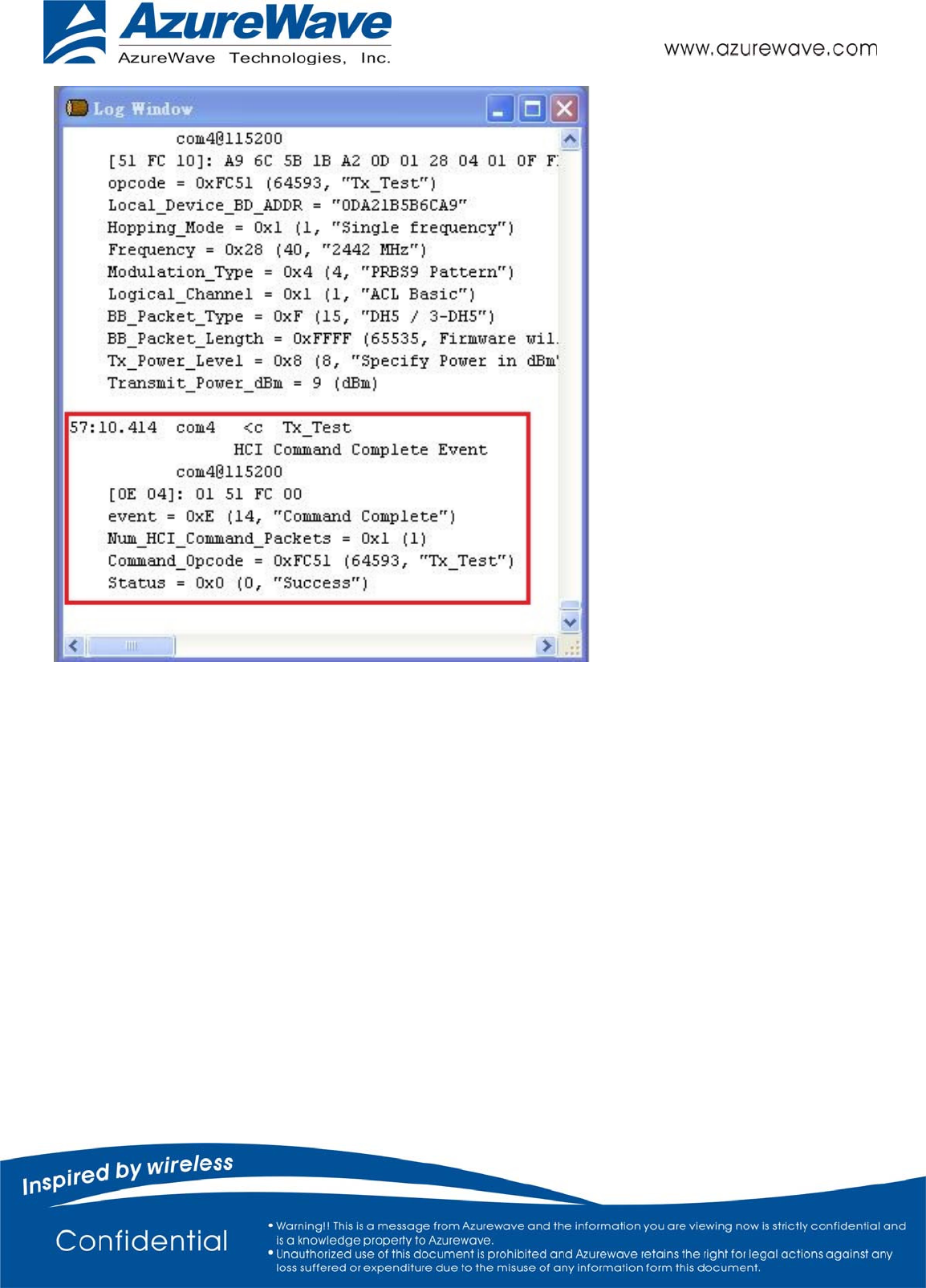
3. Confirm that this step is done successfully by viewing the log window.
- 14 -
- 15 -
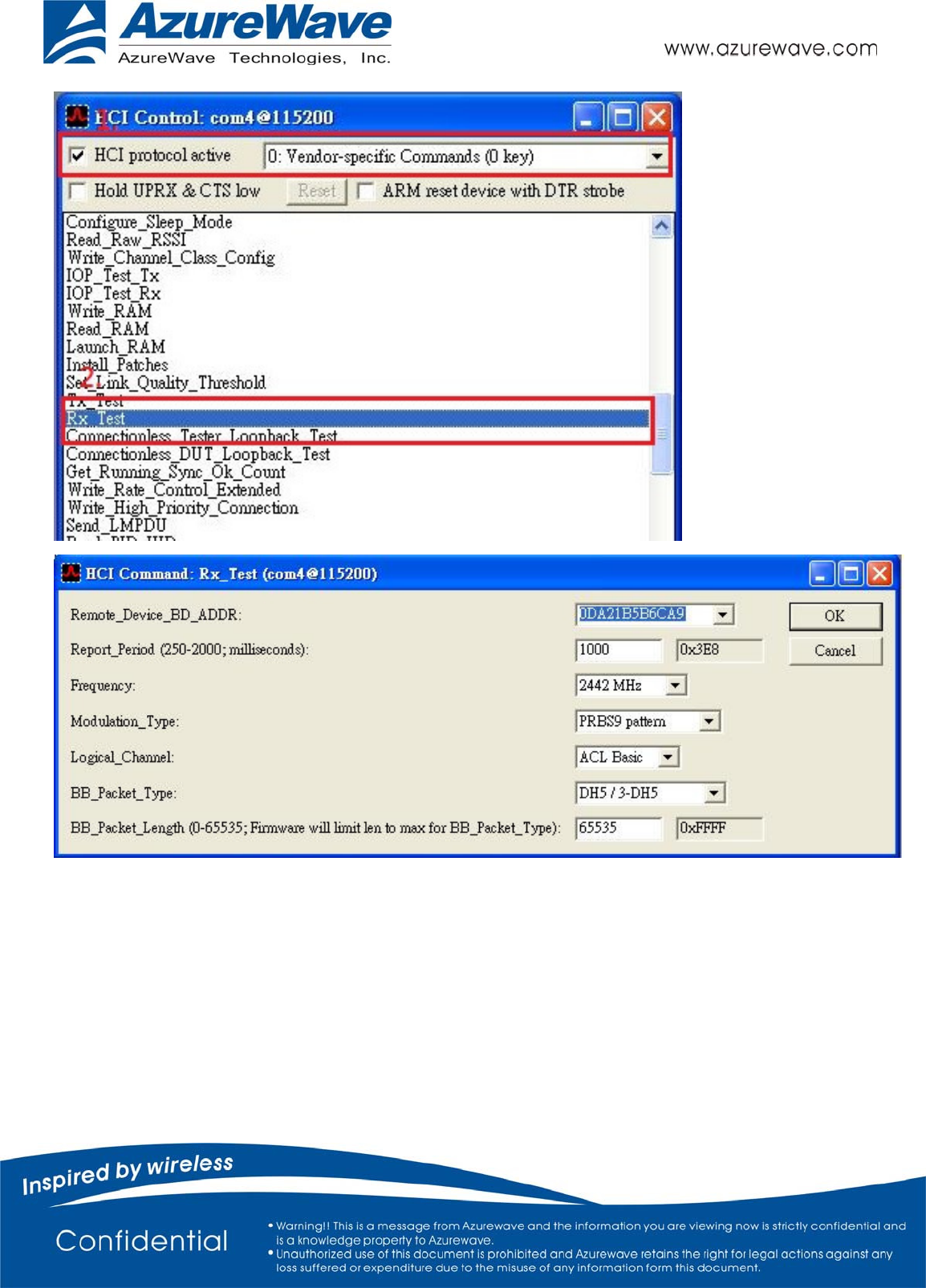
I. RX Testing
1. In the HCI Control window
a. select 0: Vendor-specific Commands (0 key) for HCI protocol active b. Double-click RX Test
2. In the HCI command window
a. From the Local_Device_BD_ADDR shortcut menu, select the Bluetooth device address of the DUT.
b. From the report period shortcut menu, select which period you want to used
c. From the frequency shortcut menu, select which frequency you want to test.
d. From the Modulation_Type shortcut menu, select PRBS9 Pattern.
e. From the Logical_Channel shortcut menu, select ACL Basic.
f. From the BB_Packet_Type shortcut menu, DH5/3-DH5, DH3/3-DH3, or DH1/2-DH1.
g. From the BB_Packet_length(….) shortcut menu, key in 65535
h. Click OK.
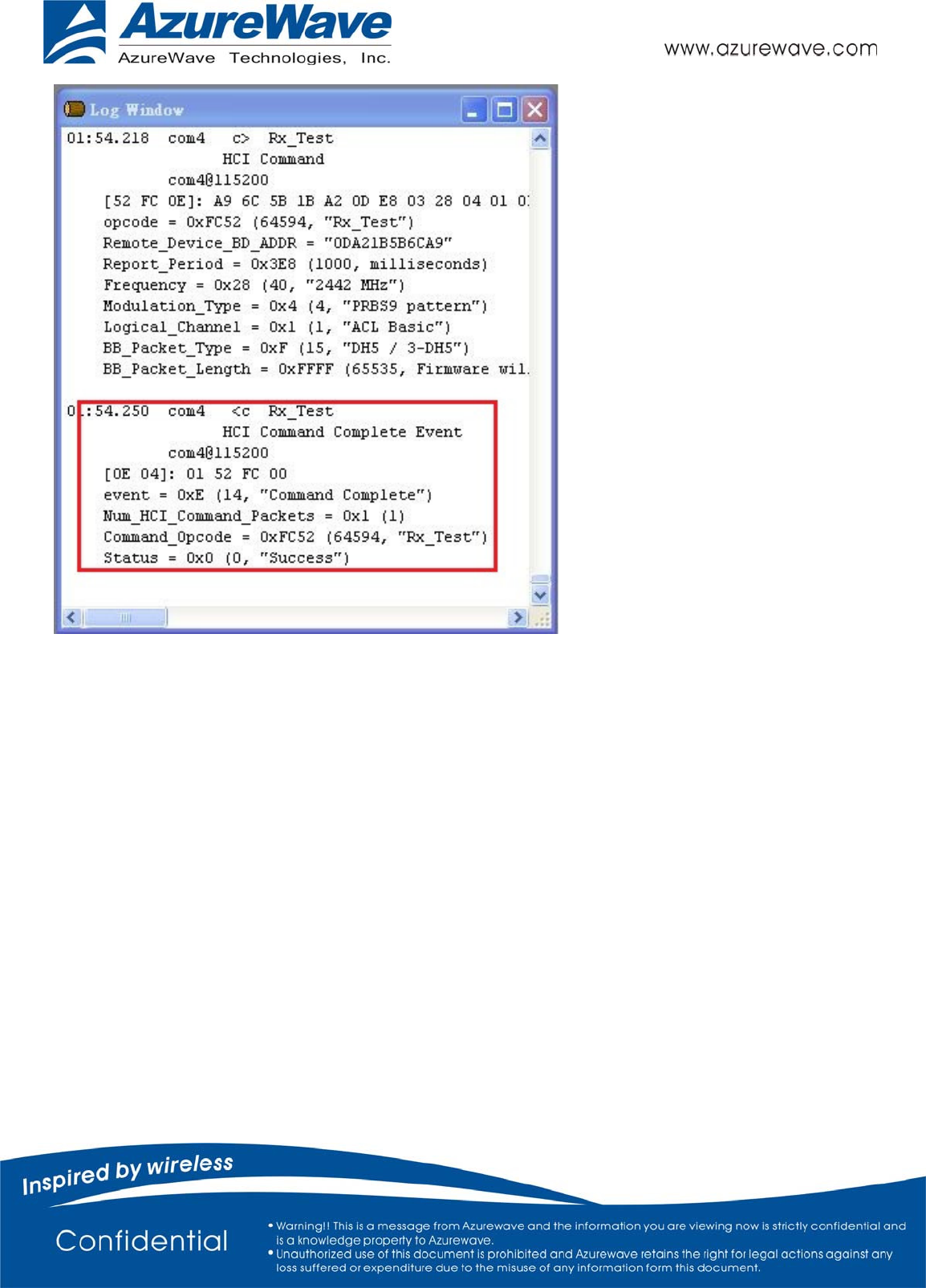
3. Confirm that this step is done successfully by viewing the log window .
- 16 -
- 17 -
Measure performance with instrument for auto testing (ex. Agilent N4010)
Step : A to G
Measure performance with instrument for manual testing (ex. Spectrum
Analyzer)
Step :A to D ,H(testing TX) or I(testing RX)
The device under test (DUT) should be reset before each procedure. Re-test or
replace the DUT need to switch Bluetool and plug DUT.
If the Log Window didn’t show successful message in any step (Step B~I),please reset
it.
- 18 -
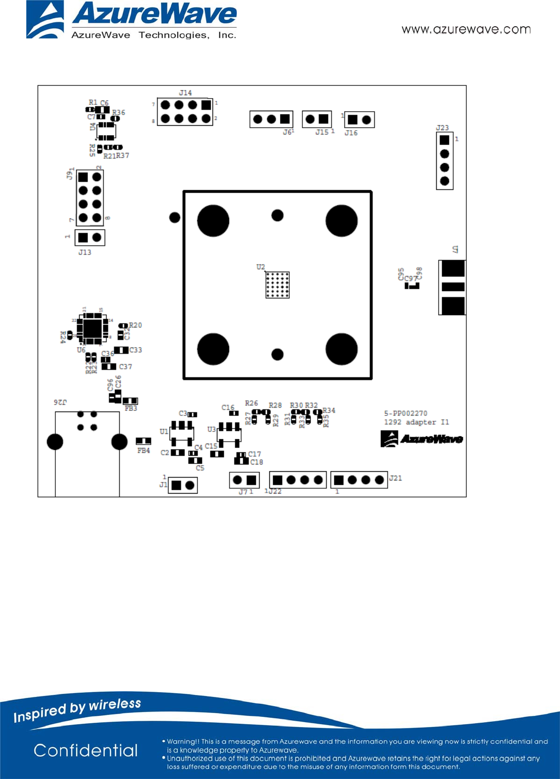
2. AW-BT715C EVB
- 21 -
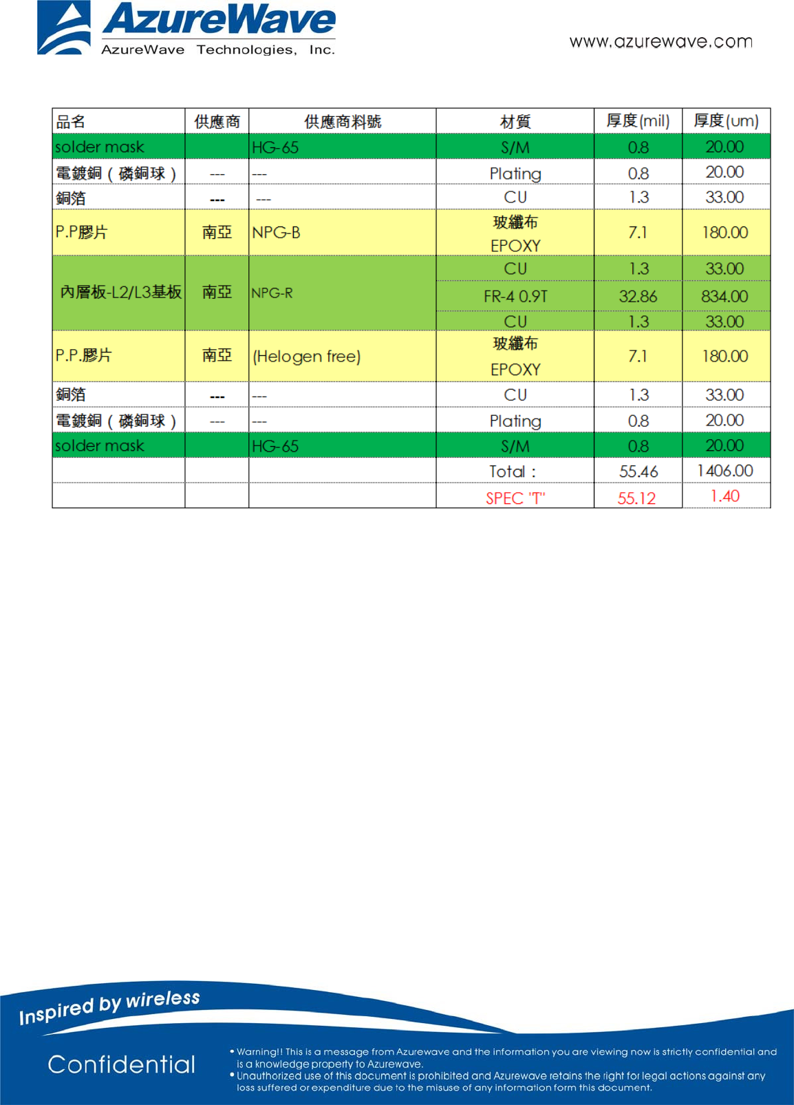
EVB PCB Stackup
Federal Communication Commission Interference Statement
This device complies with Part 15 of the FCC Rules. Operation is subject to
the following two conditions: (1) This device may not cause harmful
interference, and (2) this device must accept any interference received,
including interference that may cause undesired operation.
This equipment has been tested and found to comply with the limits for a
Class B digital device, pursuant to Part 15 of the FCC Rules. These limits
are designed to provide reasonable protection against harmful interference in a
residential installation. This equipment generates, uses and can radiate radio
frequency energy and, if not installed and used in accordance with the
instructions, may cause harmful interference to radio communications.
However, there is no guarantee that interference will not occur in a particular
installation. If this equipment does cause harmful interference to radio or
television reception, which can be determined by turning the equipment off
and on, the user is encouraged to try to correct the interference by one of the
following measures:
- Reorient or relocate the receiving antenna.
- Increase the separation between the equipment and receiver.
- Connect the equipment into an outlet on a circuit different from that
to which the receiver is connected.
- Consult the dealer or an experienced radio/TV technician for help.
FCC Caution: Any changes or modifications not expressly approved by the
party responsible for compliance could void the user's authority to operate this
equipment.
This transmitter must not be co-located or operating in conjunction with any
other antenna or transmitter.
Radiation Exposure Statement:
This equipment complies with FCC radiation exposure limits set forth for an
uncontrolled environment. This equipment should be installed and operated
with minimum distance 20cm between the radiator & your body.

This device is intended only for OEM integrators under the following conditions:
1) The antenna must be installed such that 20 cm is maintained between the
antenna and users, and
2) The transmitter module may not be co-located with any other transmitter
or antenna.
As long as 2 conditions above are met, further transmitter test will not be
required. However, the OEM integrator is still responsible for testing their
end-product for any additional compliance requirements required with this
module installed
IMPORTANT NOTE: In the event that these conditions can not be met (for
example certain laptop configurations or co-location with another transmitter),
then the FCC authorization is no longer considered valid and the FCC ID can
not be used on the final product. In these circumstances, the OEM integrator
will be responsible for re-evaluating the end product (including the transmitter)
and obtaining a separate FCC authorization.
End Product Labeling
This transmitter module is authorized only for use in device where the antenna
may be installed such that 20 cm may be maintained between the antenna and
users. The final end product must be labeled in a visible area with the
following: “Contains FCC ID: TLZ- BT715C”. The grantee's FCC ID can be
used only when all FCC compliance requirements are met.
Manual Information To the End User
The OEM integrator has to be aware not to provide information to the end user
regarding how to install or remove this RF module in the user’s manual of the
end product which integrates this module.
The end user manual shall include all required regulatory information/warning
as show in this manual.
Industry Canada statement:
This device complies with RSS-210 of the Industry Canada Rules. Operation is
subject to the following two conditions: (1) This device may not cause harmful
interference, and (2) this device must accept any interference received, including
interference that may cause undesired operation.
Ce dispositif est conforme à la norme CNR-210 d'Industrie Canada applicable aux
appareils radio exempts de licence. Son fonctionnement est sujet aux deux conditions
suivantes: (1) le dispositif ne doit pas produire de brouillage préjudiciable, et (2) ce
dispositif doit accepter tout brouillage reçu, y compris un brouillage susceptible de
provoquer un fonctionnement indésirable.
Radiation Exposure Statement:
This equipment complies with IC radiation exposure limits set forth for an
uncontrolled environment. This equipment should be installed and operated with
minimum distance 20cm between the radiator & your body.
Déclaration d'exposition aux radiations:
Cet équipement est conforme aux limites d'exposition aux rayonnements IC établies
pour un environnement non contrôlé. Cet équipement doit être installé et utilisé avec
un minimum de 20 cm de distance entre la source de rayonnement et votre corps.

This device is intended only for OEM integrators under the following conditions: (For
module device use)
1) The antenna must be installed such that 20 cm is maintained between the antenna
and users, and
2) The transmitter module may not be co-located with any other transmitter or
antenna.
As long as 2 conditions above are met, further transmitter test will not be required.
However, the OEM integrator is still responsible for testing their end-product for any
additional compliance requirements required with this module installed.
Cet appareil est conçu uniquement pour les intégrateurs OEM dans les conditions
suivantes: (Pour utilisation de dispositif module)
1) L'antenne doit être installée de telle sorte qu'une distance de 20 cm est respectée
entre l'antenne et les utilisateurs, et
2) Le module émetteur peut ne pas être coïmplanté avec un autre émetteur ou antenne.
Tant que les 2 conditions ci-dessus sont remplies, des essais supplémentaires sur
l'émetteur ne seront pas nécessaires. Toutefois, l'intégrateur OEM est toujours
responsable des essais sur son produit final pour toutes exigences de conformité
supplémentaires requis pour ce module installé.
IMPORTANT NOTE:
In the event that these conditions can not be met (for example certain laptop
configurations or co-location with another transmitter), then the Canada authorization
is no longer considered valid and the IC ID can not be used on the final product. In
these circumstances, the OEM integrator will be responsible for re-evaluating the end
product (including the transmitter) and obtaining a separate Canada authorization.
NOTE IMPORTANTE:
Dans le cas où ces conditions ne peuvent être satisfaites (par exemple pour certaines
configurations d'ordinateur portable ou de certaines co-localisation avec un autre
émetteur), l'autorisation du Canada n'est plus considéré comme valide et l'ID IC ne
peut pas être utilisé sur le produit final. Dans ces circonstances, l'intégrateur OEM
sera chargé de réévaluer le produit final (y compris l'émetteur) et l'obtention d'une
autorisation distincte au Canada.
End Product Labeling
This transmitter module is authorized only for use in device where the antenna may be
installed such that 20 cm may be maintained between the antenna and users. The final
end product must be labeled in a visible area with the following: “Contains IC:
6100A-BT715C”.
Plaque signalétique du produit final
Ce module émetteur est autorisé uniquement pour une utilisation dans un dispositif où
l'antenne peut être installée de telle sorte qu'une distance de 20cm peut être maintenue
entre l'antenne et les utilisateurs. Le produit final doit être étiqueté dans un endroit
visible avec l'inscription suivante: "Contient des IC: 6100A-BT715C".
Manual Information To the End User
The OEM integrator has to be aware not to provide information to the end user
regarding how to install or remove this RF module in the user’s manual of the end
product which integrates this module.
The end user manual shall include all required regulatory information/warning as
show in this manual.
Manuel d'information à l'utilisateur final
L'intégrateur OEM doit être conscient de ne pas fournir des informations à l'utilisateur
final quant à la façon d'installer ou de supprimer ce module RF dans le manuel de
l'utilisateur du produit final qui intègre ce module.
Le manuel de l'utilisateur final doit inclure toutes les informations réglementaires
requises et avertissements comme indiqué dans ce manuel.

低功率電波輻射性電機管理辦法
第十二條 經型式認證合格之低功率射頻電機,非經許可,公司商
號或使用者均不得擅自變更頻率加大功率或變更原設計之
特性及功能
第十四條 低功率射頻電機之使用不得影響飛航安全及干擾合法通
信;經發現有干擾現象時,應立即停用,並改善至無干擾時
方得繼續使用
前項合法通信,指依電信法規定作業之無線電通信
低功率射頻電機須忍受合法通信或工業科學及醫療用電波
輻射性電機設備之干擾
模組認證:
1. 本模組於取得認證後將依規定於模組本體標示審驗合格標籤
2. 系統廠商應於平台上標示本產品內含射頻模組:
XXXyyyLPDzzzz-x字樣