AzureWave Technologies CU282 IEEE 802.11 b/g/n Smart Energy Module User Manual
AzureWave Technologies, Inc. IEEE 802.11 b/g/n Smart Energy Module
User Manual.pdf
- 1 -
AW-CU282
Wireless LAN Module IC
MFG Tool Command User Guide
Version 0.1
Document
release Date Modification Initials Approved
Ver. 0.1 2013/3/17 Initial version Renton Tao Ivan Chen
- 2 -
Step1: Initial Command
As the information showed on your screen, please enter these commands below to start your test.
Command: 1 Wi-Fi testing mode
Step2: Generate 802.11 b/g/n Packet
(1)Command: 22 1 12 1
22: Initial transmit power in the antenna
1: Set the wanted channel (1~14 for B/G/N mode)
12: Set the wanted power, typically G mode: 12 dBm/ B mode: 15 dBm
1: Set the mode, 1G mode & N mode , 0 B mode
(2)Command: 112 0 (only for N mode)
112: N mode HT20/40.
0: for HT20/40. 0HT20, 1HT40
(3)Command: 25 1 13
25: Set duty cycle, packet mode.
1: Data rate enable
13: Data rate set up
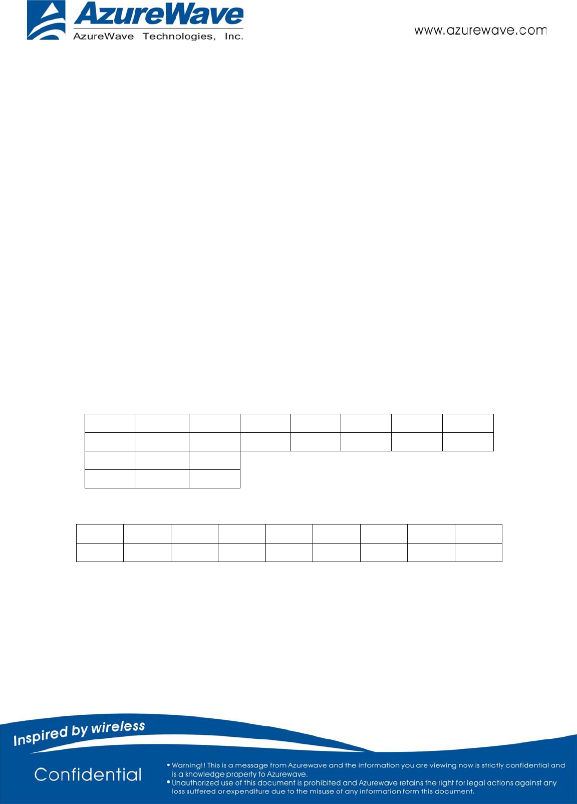
A mode &B mode & G mode
1Mbps 5.5Mbps 11Mbps 6Mbps 9Mbps 12Mbps 18Mbps 24Mbps
1 3 4 6 7 8 9 10
36Mbps 48Mbps 54Mbps
11 12 13
N mode
MCS0 MCS1 MCS2 MCS3 MCS4 MCS5 MCS6 MCS7 MCS8
15 16 17 18 19 20 21 22 23
After you type above command, you can measure the 802.11b/g/n packet by your RF test instrument (exp:
Agilent 4010, IQview…).
(4) Command: 25 0
Stop transmitting packet signal.

- 3 -
Step3: Generate 802.11b/g/n continuous symbol
(1)Please re-type the Step5 (1)~(4) commands.
(2)Command 17 1 13
17: Set continuous mode.
1: Enable data rate
13: 54 Mbps, other data rate, please refer the above table.
After you type above command, you can measure the 802.11b/g continuous symbol in your RF test
instrument.
(3)Command 17 0
Stop transmitting continuous signal
Step4: Test RX sensitivity
Before test RX, the Marvell standard waveform is needed. Please contact Azurewave FAE for
this issue.
(1) Command 12 1
12: Choose RX text channel
1: Channel number, (1~14 for B/G/N mode)
(2) Command: 112 0 (only for N mode)
112: N mode HT20/40.
0: for HT20/40. 0HT20, 1HT40
(3) 32: Check the received packets.
(4) 31: Clear all the received packets.
Step5: Others Commands
(1) Command 45 Check the MAC
(2) Command 99 Quit the test mode/ Quit the MFG tool
Federal Communication Commission Interference Statement
This device complies with Part 15 of the FCC Rules. Operation is subject to
the following two conditions: (1) This device may not cause harmful
interference, and (2) this device must accept any interference received,
including interference that may cause undesired operation.
This equipment has been tested and found to comply with the limits for a
Class B digital device, pursuant to Part 15 of the FCC Rules. These limits
are designed to provide reasonable protection against harmful interference in a
residential installation. This equipment generates, uses and can radiate radio
frequency energy and, if not installed and used in accordance with the
instructions, may cause harmful interference to radio communications.
However, there is no guarantee that interference will not occur in a particular
installation. If this equipment does cause harmful interference to radio or
television reception, which can be determined by turning the equipment off
and on, the user is encouraged to try to correct the interference by one of the
following measures:
- Reorient or relocate the receiving antenna.
- Increase the separation between the equipment and receiver.
- Connect the equipment into an outlet on a circuit different from that
to which the receiver is connected.
- Consult the dealer or an experienced radio/TV technician for help.
FCC Caution: Any changes or modifications not expressly approved by the
party responsible for compliance could void the user's authority to operate this
equipment.
This transmitter must not be co-located or operating in conjunction with any
other antenna or transmitter.
Radiation Exposure Statement:
This equipment complies with FCC radiation exposure limits set forth for an
uncontrolled environment. This equipment should be installed and operated
with minimum distance 20cm between the radiator & your body.

This device is intended only for OEM integrators under the following conditions:
1) The antenna must be installed such that 20 cm is maintained between the
antenna and users, and
2) The transmitter module may not be co-located with any other transmitter or
antenna.
3) Module approval valid only when the module is installed in the tested host
or compatible series of host
As long as 3 conditions above are met, further transmitter test will not be
required. However, the OEM integrator is still responsible for testing their
end-product for any additional compliance requirements required with this
module installed
IMPORTANT NOTE: In the event that these conditions can not be met (for
example certain laptop configurations or co-location with another transmitter),
then the FCC authorization is no longer considered valid and the FCC ID can
not be used on the final product. In these circumstances, the OEM integrator will
be responsible for re-evaluating the end product (including the transmitter) and
obtaining a separate FCC authorization.
End Product Labeling
This transmitter module is authorized only for use in device where the antenna
may be installed such that 20 cm may be maintained between the antenna and
users. The final end product must be labeled in a visible area with the following:
“Contains FCC ID: TLZ-CU282”. The grantee's FCC ID can be used only when
all FCC compliance requirements are met.
Manual Information To the End User
The OEM integrator has to be aware not to provide information to the end user
regarding how to install or remove this RF module in the user’s manual of the
end product which integrates this module.
The end user manual shall include all required regulatory information/warning as
show in this manual.
2