AzureWave Technologies CU300 IEEE 802.11 b/g/n WLAN Microcontroller Module User Manual AzureWave Technologies
AzureWave Technologies, Inc. IEEE 802.11 b/g/n WLAN Microcontroller Module AzureWave Technologies
User Manual.pdf

AW-CU300 EVB User Guide
(PCB 2223 Ver:I1,I2)
V0.2
2015/06/12
Kai. Wu

Confidential
Relative Software
Application Software
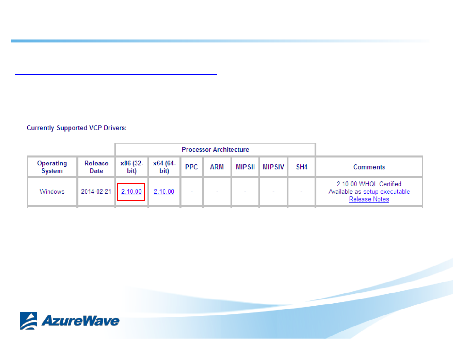
•FTDI VCP Drivers (FT2232D)
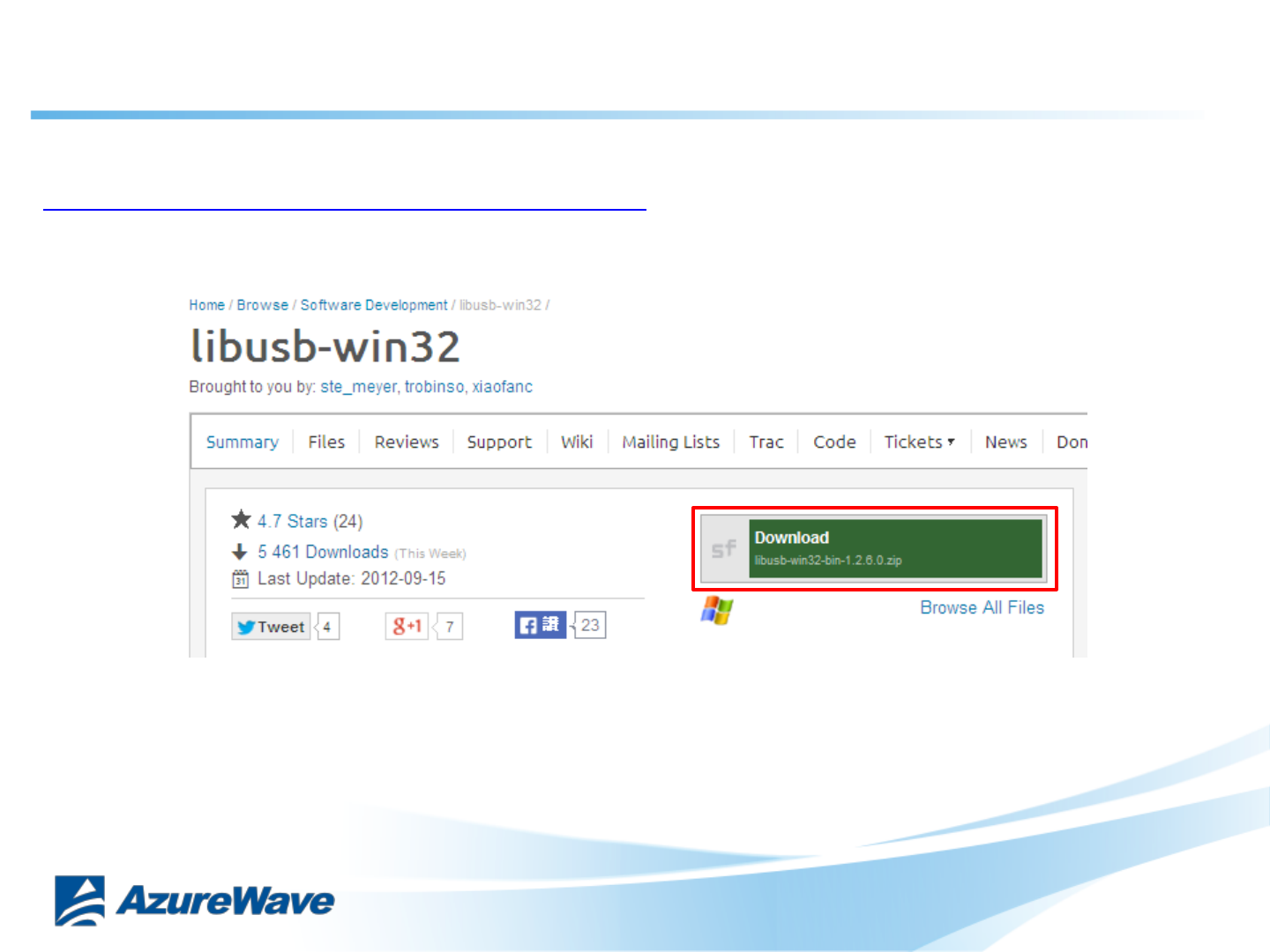
•Libusb-win32-bin-1.2.6.0
•Cygwin
Set-up Procedure
1. Download FTDI VCP Drivers (FT2232D)
2. Download Libusb-win32-bin-1.2.6.0
3. Set Up CU277 EVB for Windows
4. Install FTDI VCP Drivers
5. Install Libusb-win32-bin-1.2.6.0
6. Install Cygwin
7. Insert file “OpenOCD.zip”
8. Burning MCU Image with normal firmware
9. Run WIFI Normal Driver
10. Burning MCU Image with MFG firmware
11. Run WIFI/BT MFG tool
2
Confidential
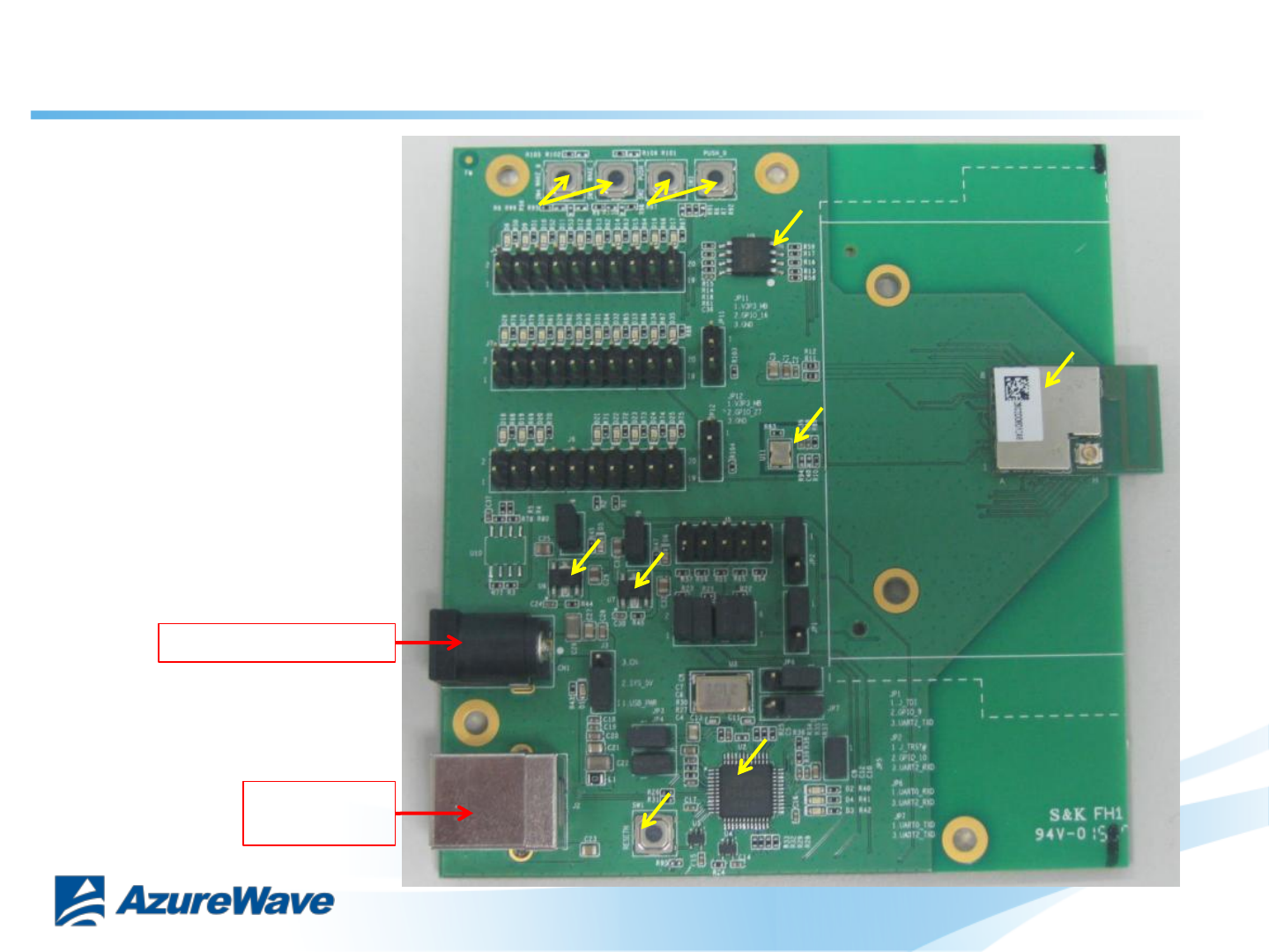
External QSPI (32M-Bit)
flash to CU300
AW-CU300
USB B-type
5V Input
FTDI USB to UART/JTAG with CU300
(COM Port 1 for CU300’s JTAG, COM Port 2 for CU300’s UART0)
External 32.768KHz to CU300
EVB Power Supply Option:
1. USB B-type 5V Input
2. Power Jack 5V Input
(If the USB B-type driving force
shortage)
LDO 5V to 3.3V
LDO 5V to 3.3V
CU300 Reset
CU300 Wake Up
Power Jack 5V Input
Relative Hardware I1
3
CU300 Push SW
Confidential
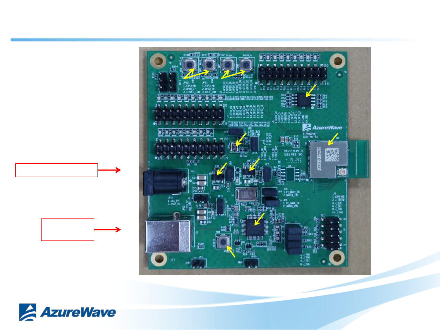
External QSPI (32M-Bit)
flash to CU300
AW-CU300
USB B-type
5V Input
FTDI USB to UART/JTAG with CU300
(COM Port 1 for CU300’s JTAG,
COM Port 2 for CU300’s UART0)
External 32.768KHz to CU300
EVB Power Supply Option:
1. USB B-type 5V Input
2. Power Jack 5V Input
(If the USB B-type driving force
shortage)
LDO 5V to 3.3V
LDO 5V to 3.3V
CU300 Reset
CU300 Wake Up
Power Jack 5V Input
Relative Hardware I2
4
CU300 Push SW
Confidential
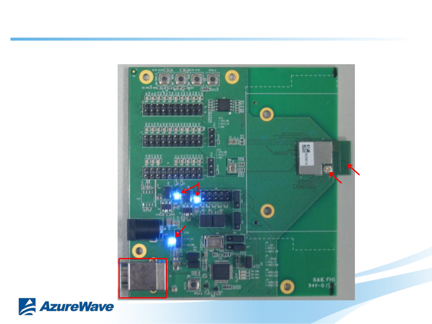
3. Set Up CU300 EVB I1 for Windows
The USB port (B type) connects the CU300 evaluation board to the PC.
ANT2
ANT1
Please refer to “AW-CU300
EVB I1’s PCB Info” document.
7
5V IN
LED
3.3V IN
LED
Confidential
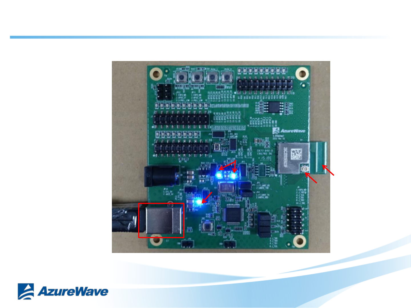
3. Set Up CU300 EVB I2 for Windows
The USB port (B type) connects the CU300 evaluation board to the PC.
ANT2
ANT1
Please refer to “AW-CU300
EVB I2’s PCB Info” document.
8
5V IN
LED
3.3V IN
LED
Confidential
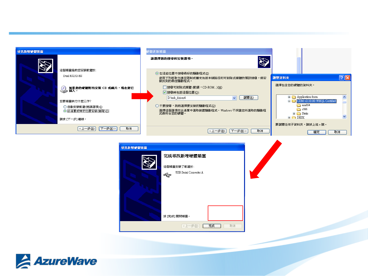
4-1. Install FTDI VCP Drivers
DONE
9
Confidential
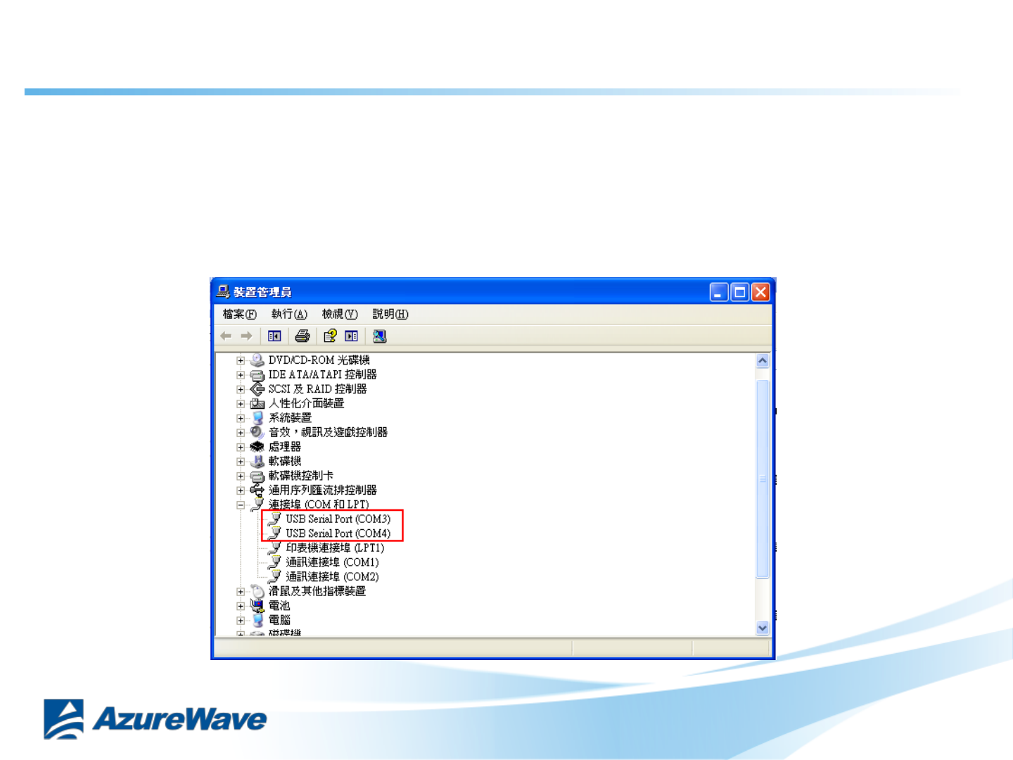
4-2. Install FTDI VCP Drivers
Verifying Driver Installation:
To verify that driver installation has completed successfully, you can open the
“Device Manager” (right-click My Computer, select Properties).
In the System Properties windows, select Hardware, Device Manager.
Two “USB Serial Port” should be listed under MY-PC\Ports (COM & LPT)
10
Confidential
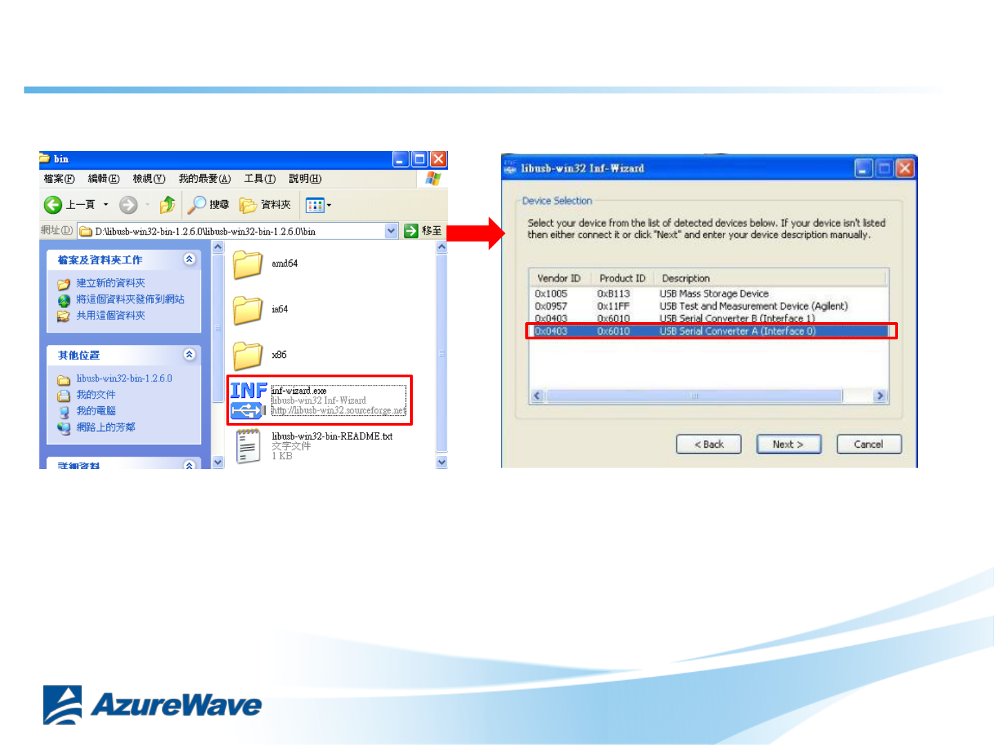
5-1. Install Libusb-win32
Install inf-wizard: USB Serial Converter A (Interface 0)
11
Confidential
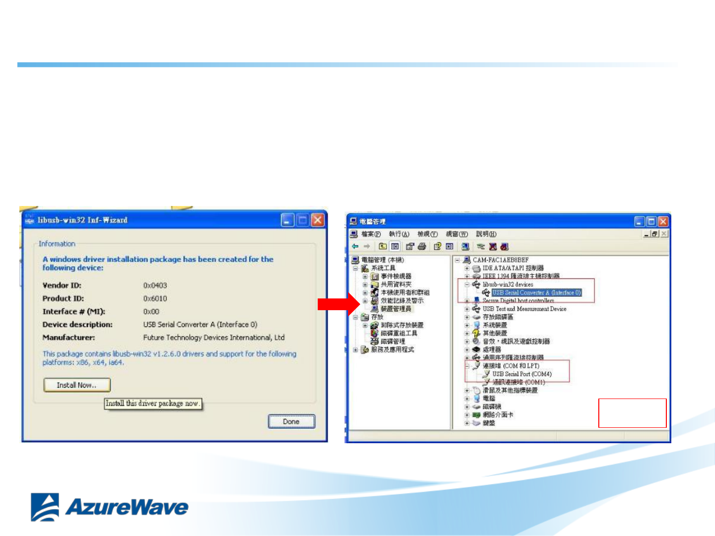
5-2. Install Libusb-win32
Verifying Driver Installation:
To verify that driver installation has completed successfully, you can open the
“Device Manager” (right-click My Computer, select Properties).
In the System Properties windows, select Hardware, Device Manager.
One “USB Serial Converter A” should be listed under MY-PC\Ports (lib usb-
win32 devices)
DONE
12

Confidential
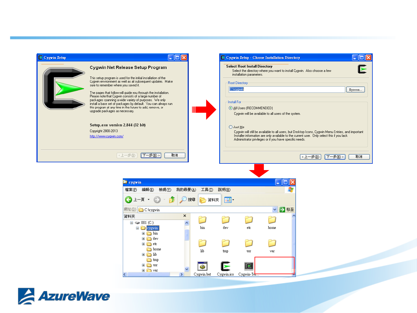
6-1. Install Cygwin
Install Cygwin:
1. Install Cygwin from: http://www.cygwin.com/setup_x86.exe (for x86 32-bit systems) or
http://www.cygwin.com/setup_x86_64.exe (for x86 64-bit systems)
2. Select the option Install from Internet
3. Use default installation path: c:\cygwin. If you chose an alternate installation directory, please
make sure that there are no spaces in the path.
4. Pick the Local Package Directory (this is the download cache directory)
5. Select the option Direct Connection
6. Select any mirror you want to use
7. Add additional packages to the default selection:
Click “Next”. The Cygwin Setup window will show the progress as each package gets installed.
Note:
If you are not familiar with cygwin, please visit http://cygwin.com/ for additional
information and details. In particular, the Cygwin User Guide
(http://cygwin.com/cygwin-ug-net/) is a good resource for new users.
13
Confidential
6-2. Install Cygwin
DONE
14
Confidential
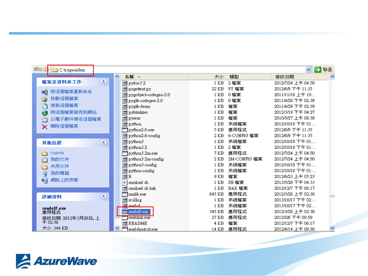
7-1. Insert file “OpenOCD.zip”
Unzip “CU300_OpenOCD.zip” and put “readelf.exe” to C:\cygwin\bin
15
Confidential
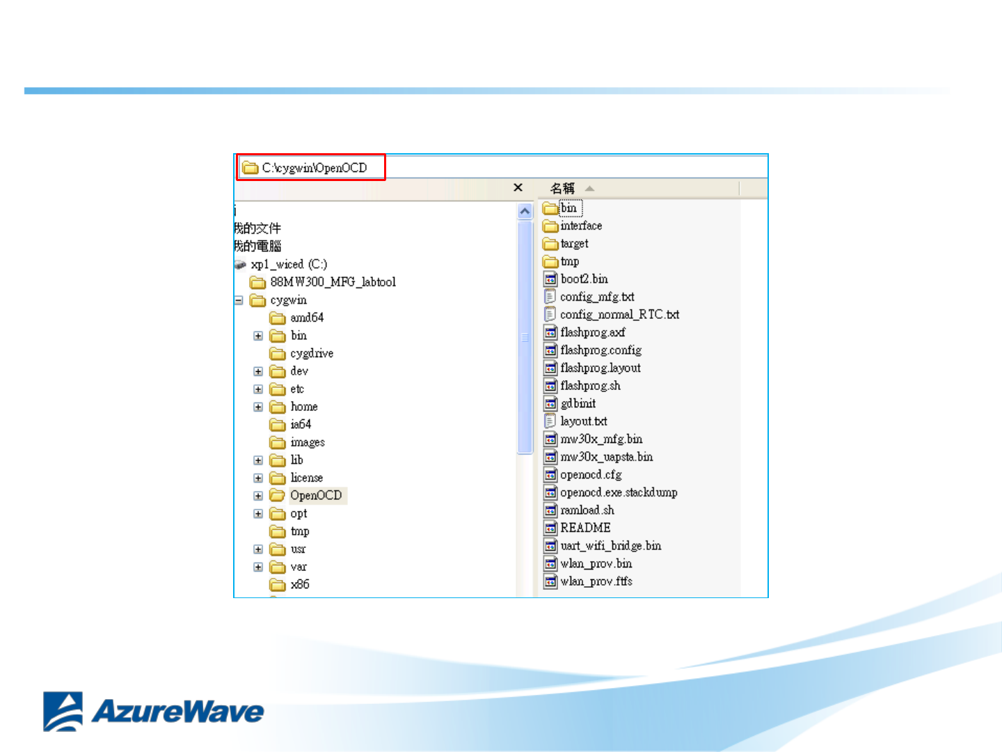
Unzip “CU300_OpenOCD.zip” and put them to C:\cygwin\
7-2. Insert file “OpenOCD.zip”
16
Confidential
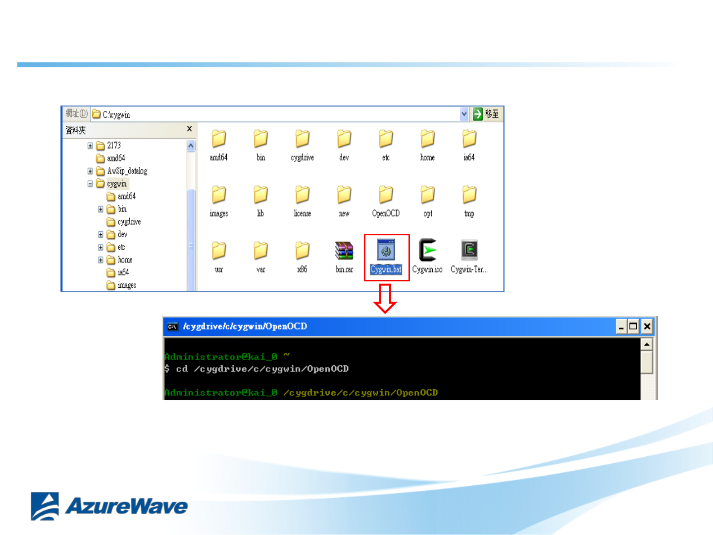
Process C:\cygwin\Cygwin.bat
7-3. Insert file “OpenOCD.zip”
17
Confidential
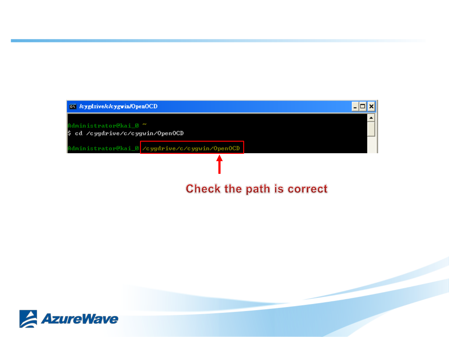
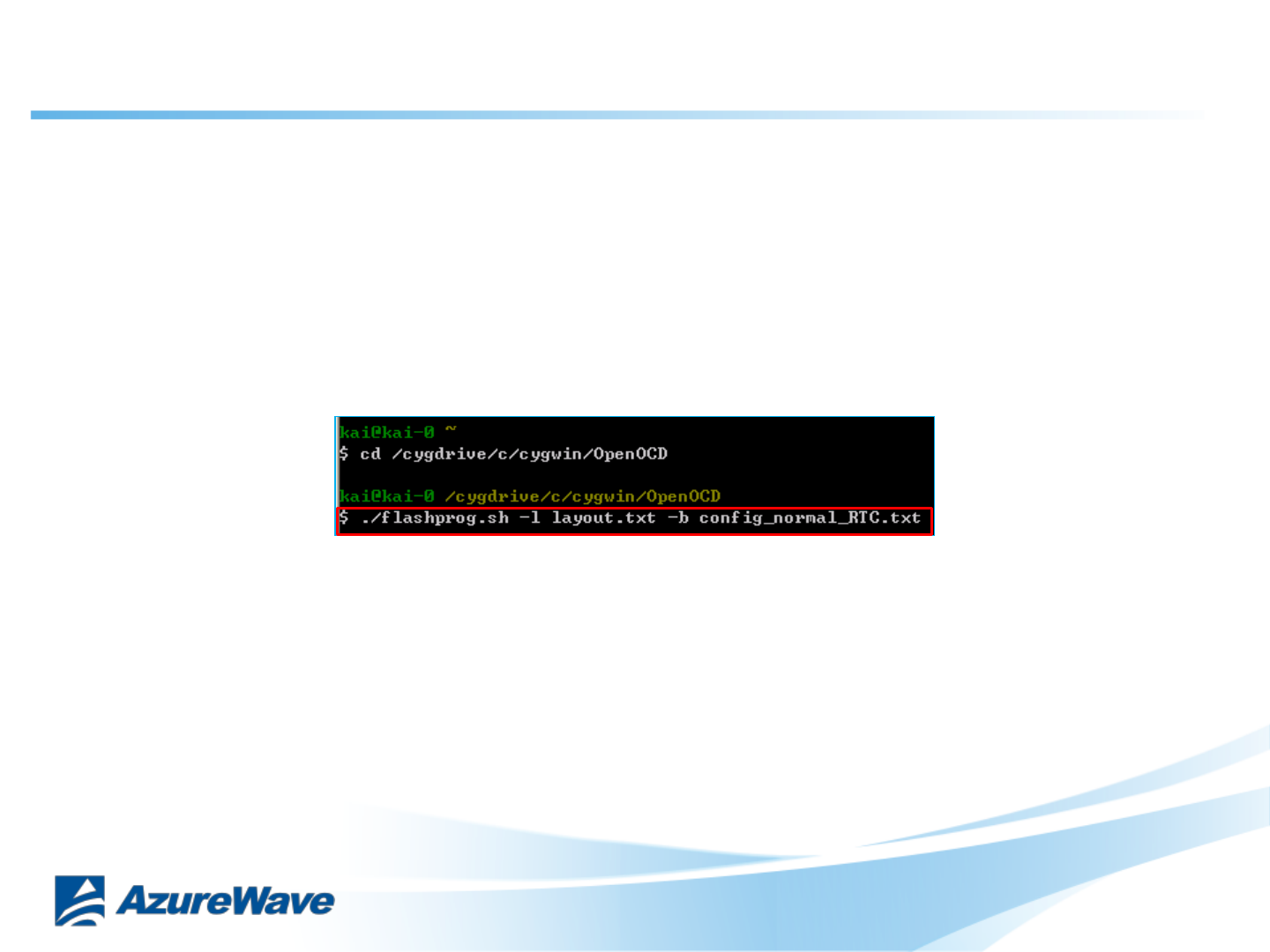
Key in command : cd /cygdrive/c/cygwin/OpenOCD
7-4. Insert file “OpenOCD.zip”
18
Confidential
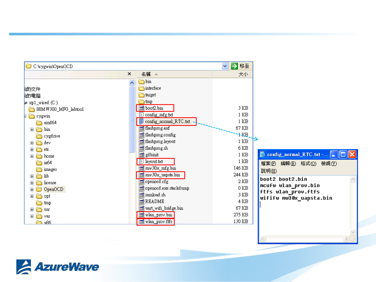
8-1. Burning Normal F/W
Check config_normal_RTC.txt, layout.txt … 6 files in the OpenOCD folder
Check path name
19
Confidential
8-2. Burning Normal F/W
Key in command : ./flashprog.sh -l layout.txt -b config_normal_RTC.txt
20
Confidential
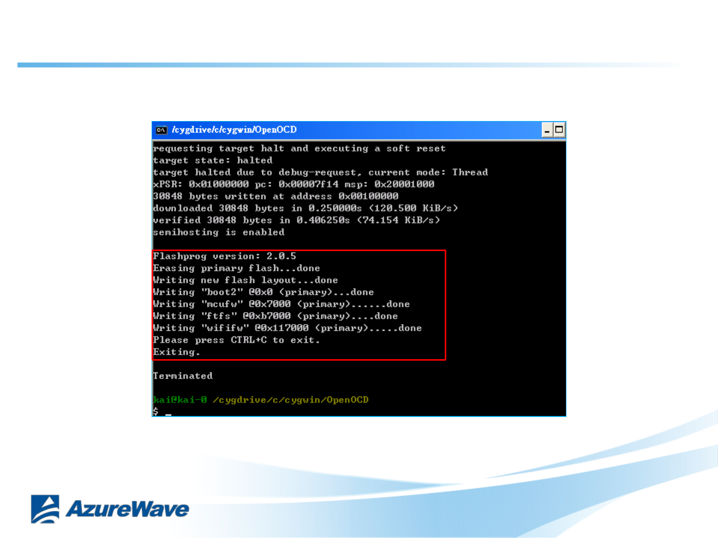
Burning information print as followed:
Note : Please restart DUT after burning (Plug-in and Plug-out USB)
8-3. Burning Normal F/W
21
Confidential
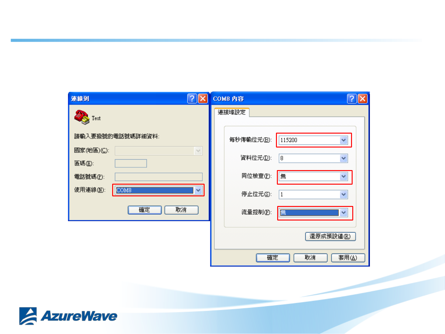
9-1. Run normal F/W
Open OS terminal and set USB comport (reference to the page9 ), set
baud-rate as 115200
off
off
115200
22
Confidential
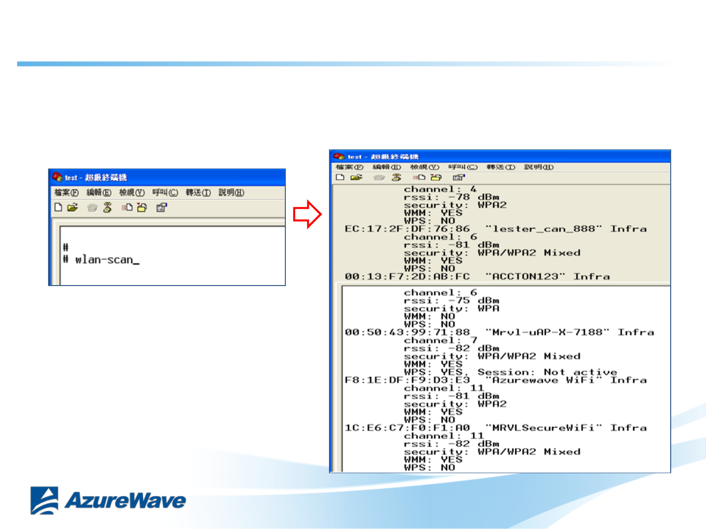
That will scan around AP
9-2. Run normal F/W
EX:
wlan-scan
Enter help on the screen to see a full list of commands available for use
23
Confidential
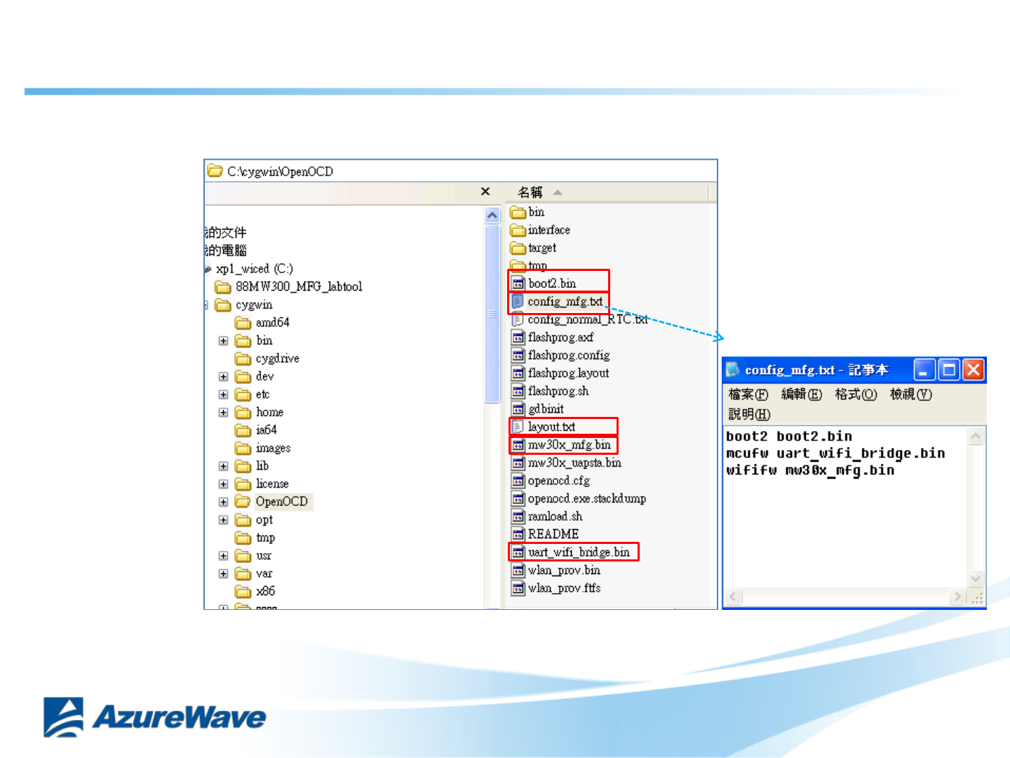
10-1. Burning MFG F/W
Check config_mfg.txt, layout.txt … 5files in OpenOCD folder
Check path name
24
Confidential
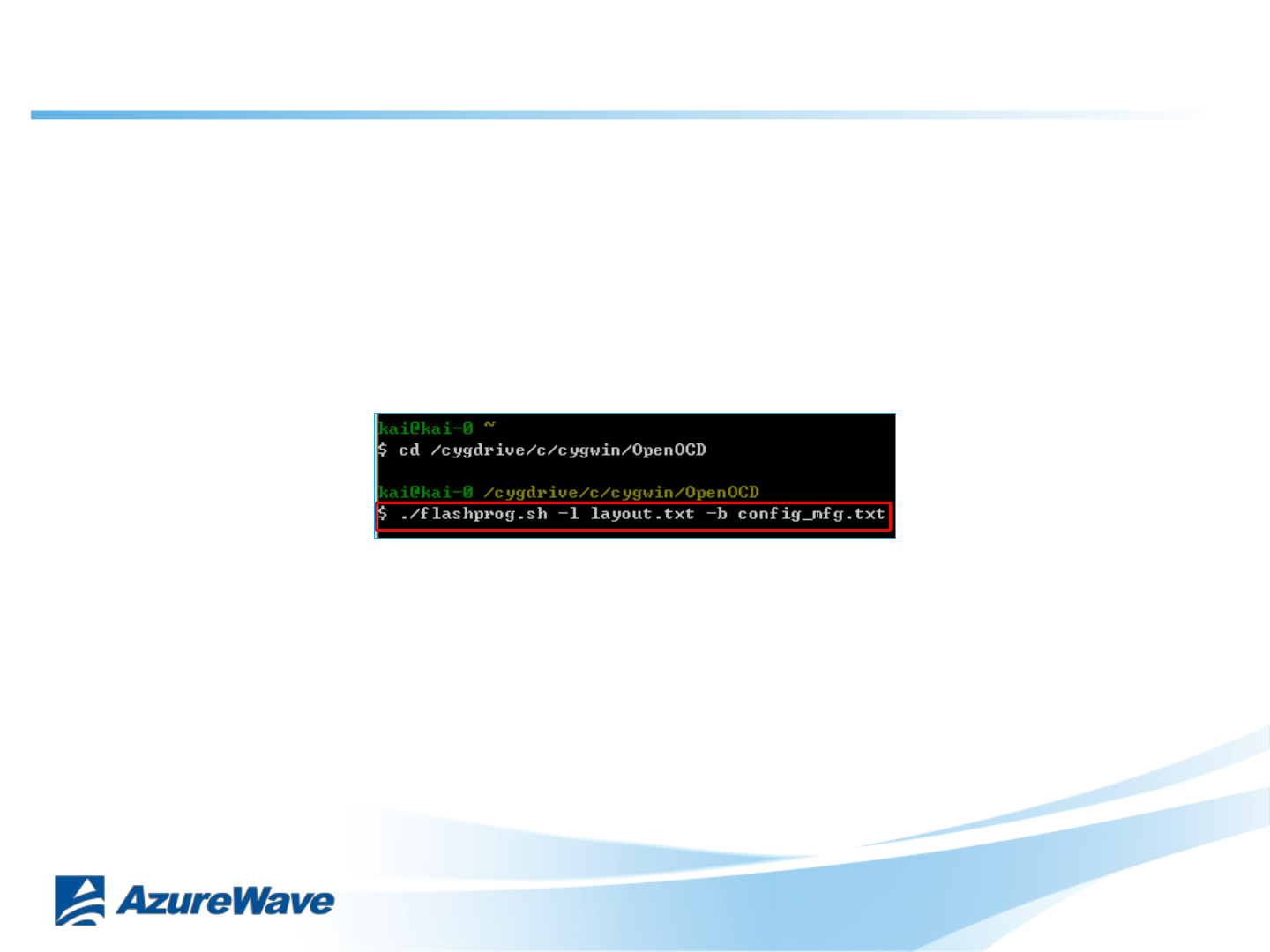
Command : ./flashprog.sh –l layout.txt –b config_mfg.txt
10-2. Burning MFG F/W
25
Confidential
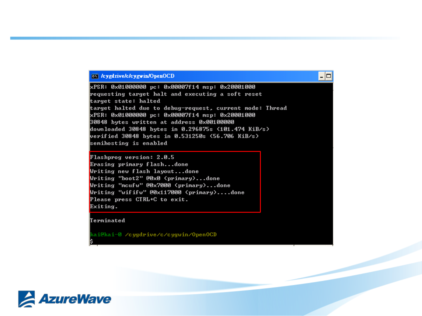
Burning information print as followed:
Note : Please restart DUT after burning (Plug-in and Plug-out USB)
10-3. Burning MFG F/W
26
Confidential
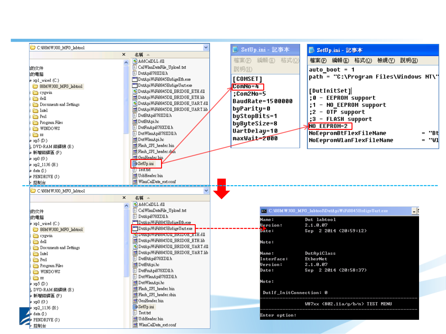
Set USB comport
Run Marvel MFG tool
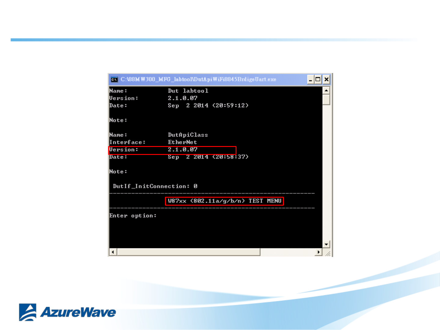
11-1. Run Marvel WIFI MFG tool
DutInitSet to 2(OTP)
27
Confidential
11-2. Run Marvel WIFI MFG tool
28
Federal Communication Commission Interference Statement
This device complies with Part 15 of the FCC Rules. Operation is subject to the
following two conditions: (1) This device may not cause harmful interference, and (2)
this device must accept any interference received, including interference that may
cause undesired operation.
This equipment has been tested and found to comply with the limits for a Class B
digital device, pursuant to Part 15 of the FCC Rules. These limits are designed to
provide reasonable protection against harmful interference in a residential installation.
This equipment generates, uses and can radiate radio frequency energy and, if not
installed and used in accordance with the instructions, may cause harmful interference
to radio communications. However, there is no guarantee that interference will not
occur in a particular installation. If this equipment does cause harmful interference
to radio or television reception, which can be determined by turning the equipment off
and on, the user is encouraged to try to correct the interference by one of the
following measures:
- Reorient or relocate the receiving antenna.
- Increase the separation between the equipment and receiver.
- Connect the equipment into an outlet on a circuit different from that
to which the receiver is connected.
- Consult the dealer or an experienced radio/TV technician for help.
FCC Caution: Any changes or modifications not expressly approved by the party
responsible for compliance could void the user's authority to operate this equipment.
This transmitter must not be co-located or operating in conjunction with any other
antenna or transmitter.
Radiation Exposure Statement:
This equipment complies with FCC radiation exposure limits set forth for an
uncontrolled environment. This equipment should be installed and operated with
minimum distance 20cm between the radiator & your body.

This device is intended only for OEM integrators under the following conditions:
The antenna must be installed such that 20 cm is maintained between the antenna and
users, and
The transmitter module may not be co-located with any other transmitter or antenna.
As long as 2 conditions above are met, further transmitter test will not be required.
However, the OEM integrator is still responsible for testing their end-product for any
additional compliance requirements required with this module installed
IMPORTANT NOTE: In the event that these conditions can not be met (for example
certain laptop configurations or co-location with another transmitter), then the FCC
authorization is no longer considered valid and the FCC ID can not be used on the
final product. In these circumstances, the OEM integrator will be responsible for
re-evaluating the end product (including the transmitter) and obtaining a separate FCC
authorization.
End Product Labeling
This transmitter module is authorized only for use in device where the antenna may be
installed such that 20 cm may be maintained between the antenna and users. The final
end product must be labeled in a visible area with the following: “Contains FCC ID:
TLZ-CU300”. The grantee's FCC ID can be used only when all FCC compliance
requirements are met.
Manual Information To the End User
The OEM integrator has to be aware not to provide information to the end user
regarding how to install or remove this RF module in the user’s manual of the end
product which integrates this module.
The end user manual shall include all required regulatory information/warning as
show in this manual.
Industry Canada statement:
This device complies with RSS-247 of the Industry Canada Rules. Operation is
subject to the following two conditions: (1) This device may not cause harmful
interference, and (2) this device must accept any interference received, including
interference that may cause undesired operation.
Ce dispositif est conforme à la norme CNR-247 d'Industrie Canada applicable aux
appareils radio exempts de licence. Son fonctionnement est sujet aux deux conditions
suivantes: (1) le dispositif ne doit pas produire de brouillage préjudiciable, et (2) ce
dispositif doit accepter tout brouillage reçu, y compris un brouillage susceptible de
provoquer un fonctionnement indésirable.
Radiation Exposure Statement:
This equipment complies with IC radiation exposure limits set forth for an
uncontrolled environment. This equipment should be installed and operated with
minimum distance 20cm between the radiator & your body.
Déclaration d'exposition aux radiations:
Cet équipement est conforme aux limites d'exposition aux rayonnements IC établies
pour un environnement non contrôlé. Cet équipement doit être installé et utilisé avec
un minimum de 20 cm de distance entre la source de rayonnement et votre corps.
This device is intended only for OEM integrators under the following conditions: (For
module device use)
1) The antenna must be installed such that 20 cm is maintained between the antenna
and users, and
2) The transmitter module may not be co-located with any other transmitter or
antenna.
As long as 2 conditions above are met, further transmitter test will not be required.
However, the OEM integrator is still responsible for testing their end-product for any
additional compliance requirements required with this module installed.
Cet appareil est conçu uniquement pour les intégrateurs OEM dans les conditions
suivantes: (Pour utilisation de dispositif module)
1) L'antenne doit être installée de telle sorte qu'une distance de 20 cm est respectée
entre l'antenne et les utilisateurs, et
2) Le module émetteur peut ne pas être coïmplanté avec un autre émetteur ou antenne.
Tant que les 2 conditions ci-dessus sont remplies, des essais supplémentaires sur
l'émetteur ne seront pas nécessaires. Toutefois, l'intégrateur OEM est toujours
responsable des essais sur son produit final pour toutes exigences de conformité
supplémentaires requis pour ce module installé.
IMPORTANT NOTE:
In the event that these conditions can not be met (for example certain laptop
configurations or co-location with another transmitter), then the Canada authorization
is no longer considered valid and the IC ID can not be used on the final product. In
these circumstances, the OEM integrator will be responsible for re-evaluating the end
product (including the transmitter) and obtaining a separate Canada authorization.
NOTE IMPORTANTE:
Dans le cas où ces conditions ne peuvent être satisfaites (par exemple pour certaines
configurations d'ordinateur portable ou de certaines co-localisation avec un autre
émetteur), l'autorisation du Canada n'est plus considéré comme valide et l'ID IC ne
peut pas être utilisé sur le produit final. Dans ces circonstances, l'intégrateur OEM
sera chargé de réévaluer le produit final (y compris l'émetteur) et l'obtention d'une
autorisation distincte au Canada.
End Product Labeling
This transmitter module is authorized only for use in device where the antenna may be
installed such that 20 cm may be maintained between the antenna and users. The final
end product must be labeled in a visible area with the following: “Contains IC:
6100A-CU300”.
Plaque signalétique du produit final
Ce module émetteur est autorisé uniquement pour une utilisation dans un dispositif où
l'antenne peut être installée de telle sorte qu'une distance de 20cm peut être maintenue
entre l'antenne et les utilisateurs. Le produit final doit être étiqueté dans un endroit
visible avec l'inscription suivante: "Contient des IC: 6100A-CU300".
Manual Information To the End User
The OEM integrator has to be aware not to provide information to the end user
regarding how to install or remove this RF module in the user’s manual of the end
product which integrates this module.
The end user manual shall include all required regulatory information/warning as
show in this manual.
Manuel d'information à l'utilisateur final
L'intégrateur OEM doit être conscient de ne pas fournir des informations à l'utilisateur
final quant à la façon d'installer ou de supprimer ce module RF dans le manuel de
l'utilisateur du produit final qui intègre ce module.
Le manuel de l'utilisateur final doit inclure toutes les informations réglementaires
requises et avertissements comme indiqué dans ce manuel.