AzureWave Technologies GA821 IEEE 802.11 b/g PCI-Express Wireless Module User Manual modified
AzureWave Technologies, Inc. IEEE 802.11 b/g PCI-Express Wireless Module modified
User manual

AW-GA821 802.11 b/g PCI Express Wireless Module
User Manual
ii
COPYRIGHT
AzureWave Technologies, Inc. All rights reserved. No part of this document may be reproduced,
transmitted, transcribed, stored in a retrieval system, or translated into any language in any
form or by any means without the written permission of AzureWave Technologies, Inc.
DISCLAIMER
AzureWave provides this document “as is”, without warranty of any kind, neither expressed nor
implied, including, but not limited to, the particular purpose. AzureWave may make
improvements and/or changes in this document or in the product described in this document at
any time. This document could include technical inaccuracies or typographical errors.
TRADEMARKS
AzureWave is a trademark of AzureWave Technologies, Inc. Other names mentioned in this
document are trademarks/registered trademarks of their respective owners.
USING THIS DOCUMENT
This document provides detailed user guidelines to provide AzureWaveIEEE 802.11 b/g
PCI-Express Wireless Moduleoperation and setting-up. Though every effort has been made to
assure that this document is current and accurate, more information may have become
available subsequent to the production of this guide. In that event, please contact your
AzureWave representative for additional information that may help in the development process.

iii
Contents
Safety statements............................................................................................................2-1
About this guide...............................................................................................................2-1
AW-GA800BTIEEE 802.11 b/g PCI-Express Wireless Modulespecification summary...............2-2
Chapter 1 Product Information........................................................................................2-2
1.1 Product overview.................................................................................................2-2
1.2 Features..............................................................................................................2-2
1.3 LED and antenna port..............................................................................................
1.4 Supported network setup.....................................................................................2-3
1.4.1 Ad-Hoc mode.............................................................................................2-4
1.4.2 Infrastructure mode...................................................................................2-4
1.4.3 Software access point (Soft AP)..................................................................2-5
Chapter 2 Installation.....................................................................................................2-1
2.1 System requirements...........................................................................................2-1
2.2 Hardware Installation...........................................................................................2-1
Chapter 3 WiFi-AP Solo Wizard.......................................................... 錯誤! 尚未定義書籤。
3.1 Launch WiFi-AP Solo Wizard.................................................................................3-2
3.2 Wi-Setup Wizard Steps.........................................................................................3-3
3.3 Station Mode Configuration..................................................................................3-3
3.3.1 Configure Infrastructure type network.........................................................3-4
3.3.2 Build Ad-Hoc networking mode network......................................................3-5
3.4 Build Soft AP network..........................................................................................3-6
3.4.1 Normal User.................................................................. 錯誤! 尚未定義書籤。
3.4.2 Advanced User.........................................................................................3-11
Chapter 4 AsusWLAN: Wireless LAN Management GUI.....................................................4-1
4.1 How to Launch AsusWLAN....................................................................................4-3
4.2 Introduction of Main Window................................................................................4-3
4.3 Station mode.......................................................................................................4-6
4.3.1 Infrastructure and Ad-Hoc..........................................................................4-7
4.4 AP mode...........................................................................................................4-12
4.5 Windows Zero Configuration...............................................................................4-15
4.5.1 Swap from AsusWLAN to Windows Zero Configuration................................4-15
4.5.2 Rollback from Windows Zero Configuration to AsusWLAN...........................4-16
Appendix A: Mapping of country and channel plan.........................................................4-1
Appendix B: Q&A.........................................................................................................4-4
Appendix C: Release History.........................................................................................4-5
2
-
1
Safety statements
FCC Radiation Exposure Statement:
This equipment complies with FCC radiation exposure limits set forth for an uncontrolled
environment. This transmitter must not be co-located or operating in conjunction with any other
antenna or transmitter.
About this guide
The user guide contains the information you need to install and configure your
AzureWave802.11 b/g PCI Express WLAN Module.
Guide organization
This guide contains the following chapters:
l Chapter 1: Product Information
This chapter describes the general functionality, features and configuration modes of
AzureWave802.11 b/g PCI Express WLAN Module.
l Chapter 2: Installation
It is recommended that users should read this chapter before installing both
AzureWaveIEEE 802.11 b/g PCI-Express Wireless Modulehardware and software. This
chapter presents the systematic installation of AzureWaveIEEE 802.11 b/g PCI-Express
Wireless Moduleand antenna, utilities and driver on the support CD.
l Chapter 3: W-Set Wizard
This chapter shows you the setup of wireless network in your office or home. Follow The
step-by-step direction provided by WiFi-AP Solo Wizard, you can have your own wireless
local area network up and running very quickly.
l Chapter 4: Management GUI
This chapter teaches you the proper operations of selected mode from W-Set Wizard. The
GUI display network status, connection profiles and network traffic to help you monitor and
manage the network configuration.

2
-
2
AzureWaveIEEE 802.11 b/g PCI-Express Wireless
Modulespecification summary
Host system connections
Interface Fully complies with PCI Express 1.0a interface.
Chapter 1 Product Information
1.1 Product overview
Thank you for choosing AzureWave802.11 b/g PCI Express WLAN Module.
The AzureWaveIEEE 802.11 b/g PCI-Express Wireless Moduleis an easy-to-use wireless local
area network (WLAN) adapter which is designed for home or office use. Direct Sequence
Spread Spectrum (DSSS), Complementary Code Keying (CCK), and Orthogonal Frequency
Division Multiplexing (OFDM) base band processing are implemented to support all IEEE
802.11b, and 802.11g data rates. Differential phase shift keying modulation schemes, DBPSK
and DQPSK with data scrambling capability, are available, along with complementary code
keying to provide data rates of 1, 2, 5.5, and 11Mbps, with long or short preamble. A high-speed
Fast Fourier Transform (FFT)/Inverse Fast Fourier Transform (IFFT) combined with BPSK,
QPSK, 16QAM and 64QAM modulation of the individual sub-carriers provides data rates of 6, 9,
12, 18, 24, 36, 48 and 54Mbps, with rate-compatible punctured convolution coding with a
coding rate of 1/2, 2/3, and 3/4.
The AzureWaveIEEE 802.11 b/g PCI-Express Wireless Modulealso supports Wake-On-LAN
(WOL) function and remote wake-up giving you the convenience to remote log in from other
places to this system.
To provide efficient security to your wireless communication, the hardware-based IEEE 802.11i
encryption/decryption engine, including 64-bit/128-bit WEP, TKIP, and AES, supports Wi-Fi
alliance WPA and WPA2 security.
With these features and many more, AzureWaveIEEE 802.11 b/g PCI-Express Wireless
Moduleis ready to connect you to the world of wireless communication.
1.2 Features
System requirements

2
-
3
The AzureWaveIEEE 802.11 b/g PCI-Express Wireless Moduleis an on-board component on
ASUS motherboard requiring manual installation. Make sure that your system meets the
following requirements.
l ASUS motherboard with AzureWaveIEEE 802.11 b/g PCI-Express Wireless
Moduleon-board solution
l Minimum 64MB system memory
l Operating system
Station mode : Windows® 2000/XP/Server 2003, Windows XP/Server 2003 x64
AP/wireless bridge mode : Windows® 2000/XP/Server 2003
l Optical drive for utilities and driver installation
Easy hardware installation
Because the AzureWaveIEEE 802.11 b/g PCI-Express Wireless Modulecomes embedded in
motherboard, no hardware installation is necessary. Just connect the antenna, install the driver
and utilities from the motherboard support CD and start wireless communication immediately.
54Mbps speed wireless travel
The AzureWaveIEEE 802.11 b/g PCI-Express Wireless Moduleprovides up to five times more
data transmission than IEEE 802.11b standards, and breaks the wireless transmission barrier to
speed up the internet connection.
WiFi-AP Solo Wizard
Easy-use wireless LAN setup wizard helps you to connect with present wireless network. The
step-by-step wizard provides a convenient way tofacilitate the complex wireless LAN setup
process.
Automatic wireless establishment
The utility application of AzureWaveAR2425 Wireless LAN PCI Express Module automatically
searches and reports the hot spots around it and the wireless signal quality and WEP capability
associated with each hot spot. Then you could connect to the most suitable wireless node
1.3 Supported network setup
You can use AzureWaveIEEE 802.11 b/g PCI-Express Wireless Modulein various wireless
network configurations. We recommend you to select the most appropriate configuration for
your home or office network before setting it up.
2
-
4
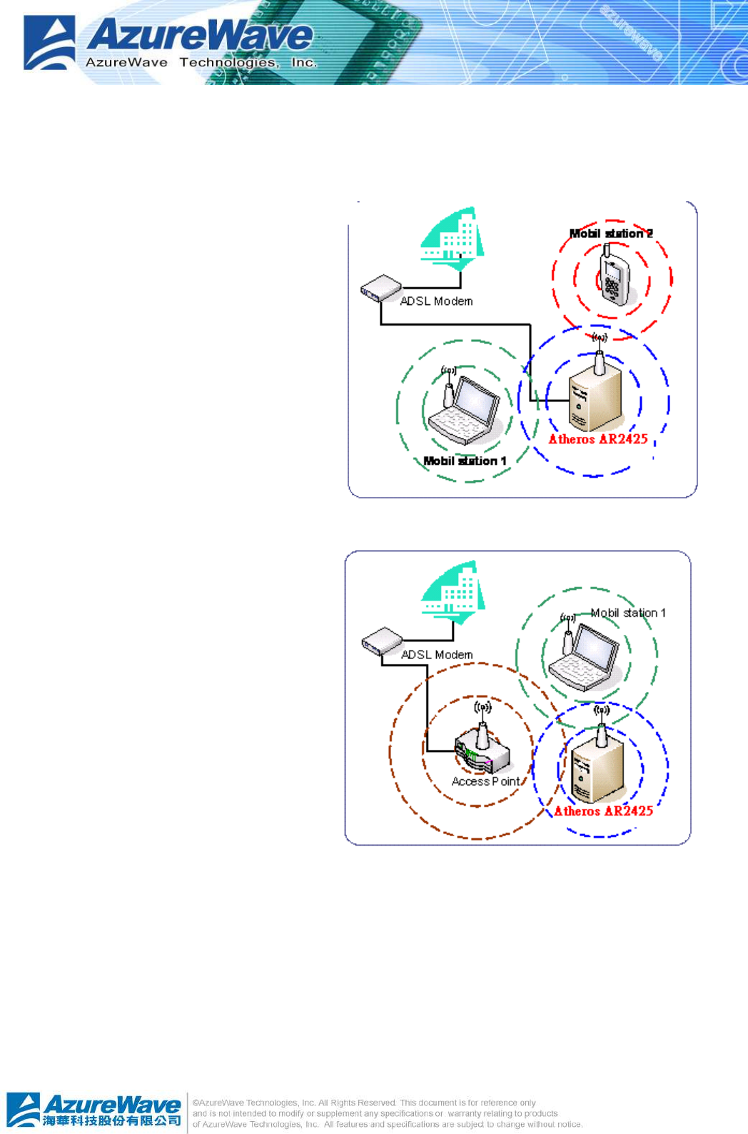
1.3.1 Ad-Hoc mode
Ad-Hoc wireless networks bring together workstations and computers to act as servers to all
other users on the network without
complex infrastructure, setup or
administration. Users on the network can
share files, printers. When in ad hoc mode,
the AzureWaveIEEE 802.11 b/g
PCI-Express Wireless Moduleconnects to
another wireless device within its effective
range and communicates with each other
in the same LAN workgroup. Select this
configuration when no access point is
present in your wireless network.
1.3.2 Infrastructure mode
The biggest difference between
infrastructure mode and ad-hoc mode is
that it includes an access point. In
infrastructure mode, an access point
establishes the network that provides
wireless links in the validating range for
clients to communicate with each other
or with a wired network to the internet.
On an infrastructure network, the access
point may manag the bandwidth to
maximize utilization. Infrastructure
networking has the following advantages over ad-hoc networking:
l Range Extension
Each wireless LAN enabled computer within the range of the access point can communicate
with other wireless LAN enabled computers within the valid range of signal from the access
point.
l Roaming
A wireless LAN enabled computer can physically move from the operating range of one
access point to another without losing connection to the LAN. A quick association
2
-
5
“hand-shake” is made between the new access point and the wireless device as the
computer traverses from the coverage of one access point to another.
l Wired to wireless LAN connectivity
Access point establishes the bridge between wireless LAN and other wired counterparts.
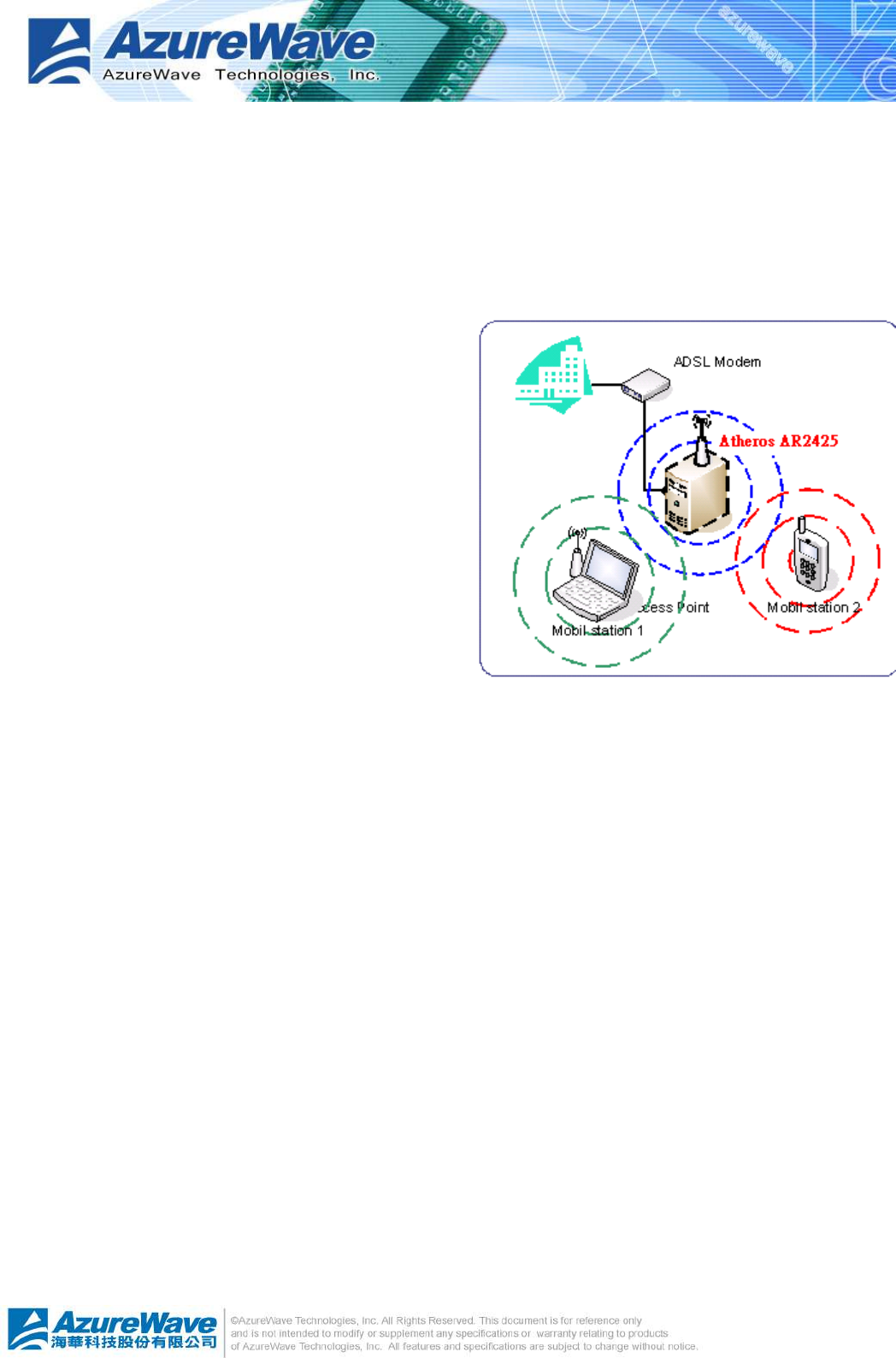
1.3.3 Software access point (Soft AP)
You could configure AzureWaveIEEE 802.11 b/g
PCI-Express Wireless Moduleas a software
access point (soft AP). In this mode, the
AzureWaveIEEE 802.11 b/g PCI-Express
Wireless Moduleacts as the access point that
provides wireless links in the validating range to
client stations to the internet.
Your system should satisfy the following two
requirements to apply this mode:
l The system you use already connects to the
internet or intranet through another one
Ethernet adapter.
l You are using Windows® 2000, XP or Server2003 operation system
Notice: Windows XP/Server2003 x64 platforms are not supported to have software access point
capability.
2
-
1
Chapter 2 Installation
2.1 System requirements
Before installing the AzureWave802.11 b/g PCI Express WLAN Module, driver and utilities,
make sure your system satisfy the following requirements
l ASUS motherboard with AzureWaveIEEE 802.11 b/g PCI-Express Wireless
Modulespecific slot
l Intel® Pentium™ 4
l Minimum 64MB system memory
l Windows® Operation System
Ad-Hoc and infrastructure mode: Windows® 2000, XP and Server 2003
Software AP and Wireless Bridge: Windows® XP and Server 2003
l Optical drive for driver and utilities installation
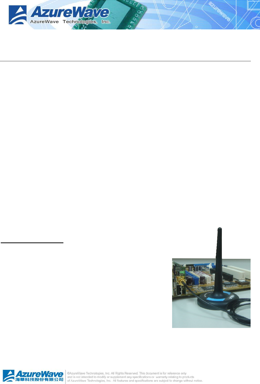
2.2 Hardware Installation
To complete the hardware installation of AzureWave802.11 b/g PCI Express WLAN Module,
you only need to install the moveable dipolar antenna at the
rear of motherboard.
Installing the antenna:
l Locate the wireless LAN antenna port on the motherboard
rear panel.
l Connect the antenna twist-on connector (female) to the
wireless LAN antenna port (male)
l Place the antenna at an elevated location to enhance your
wireless LAN valid coverage.
3
-
2
Chapter 3 WiFi-AP Solo Wizard
3.1 Launch WiFi-AP Solo Wizard
In this section, you will obtaindetail instructionin setting wireless configuration by following
WiFi-AP Solo Wizard. Please refer to Chapter 1.4 to understand the network types the
AzureWaveIEEE 802.11 b/g PCI-Express Wireless Modulesupports.
In the first time installation, WiFi-AP Solo Wizard is executed immediately after installation to
help you set the proper wireless configuration.
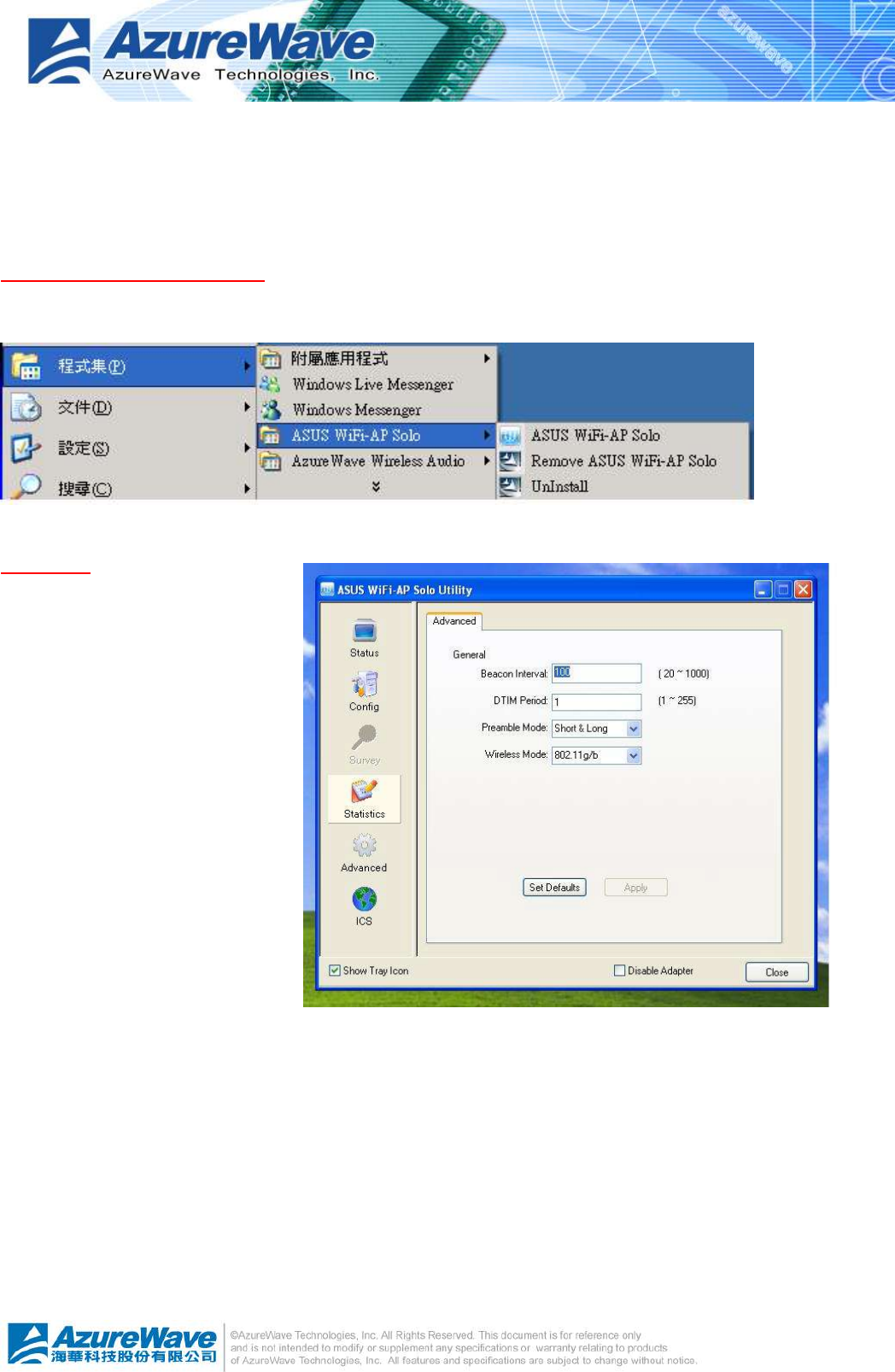
In addition, you could launch it from either program menu
or Wireless LAN Management GUI.
In the following sections, we represent
the steps, the convenient and easy
wireless set up, in WiFi-AP Solo
Wizard.
3
-
3
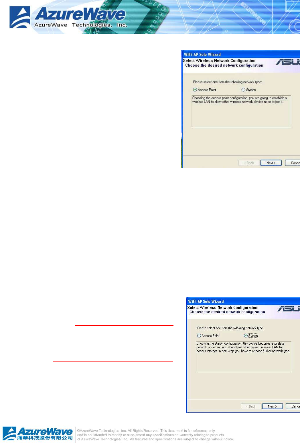
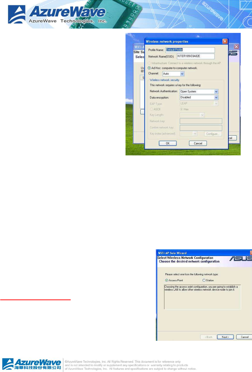
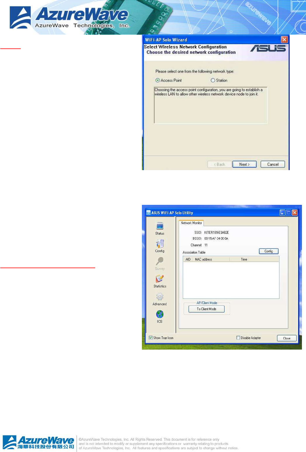
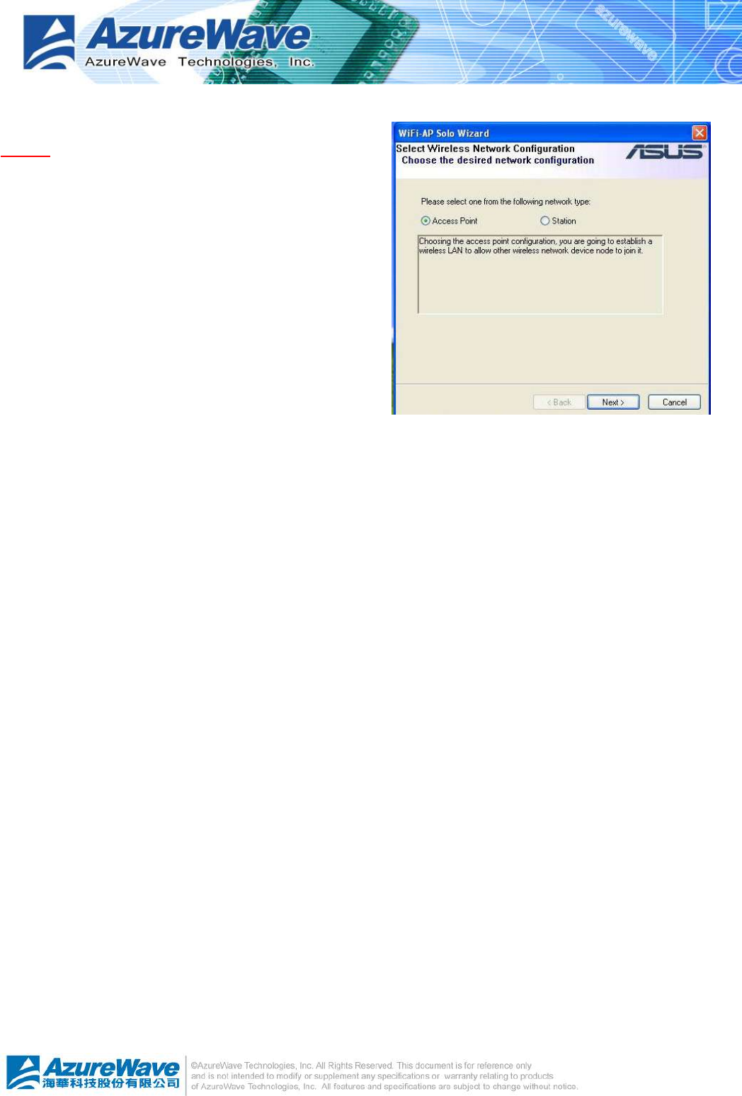
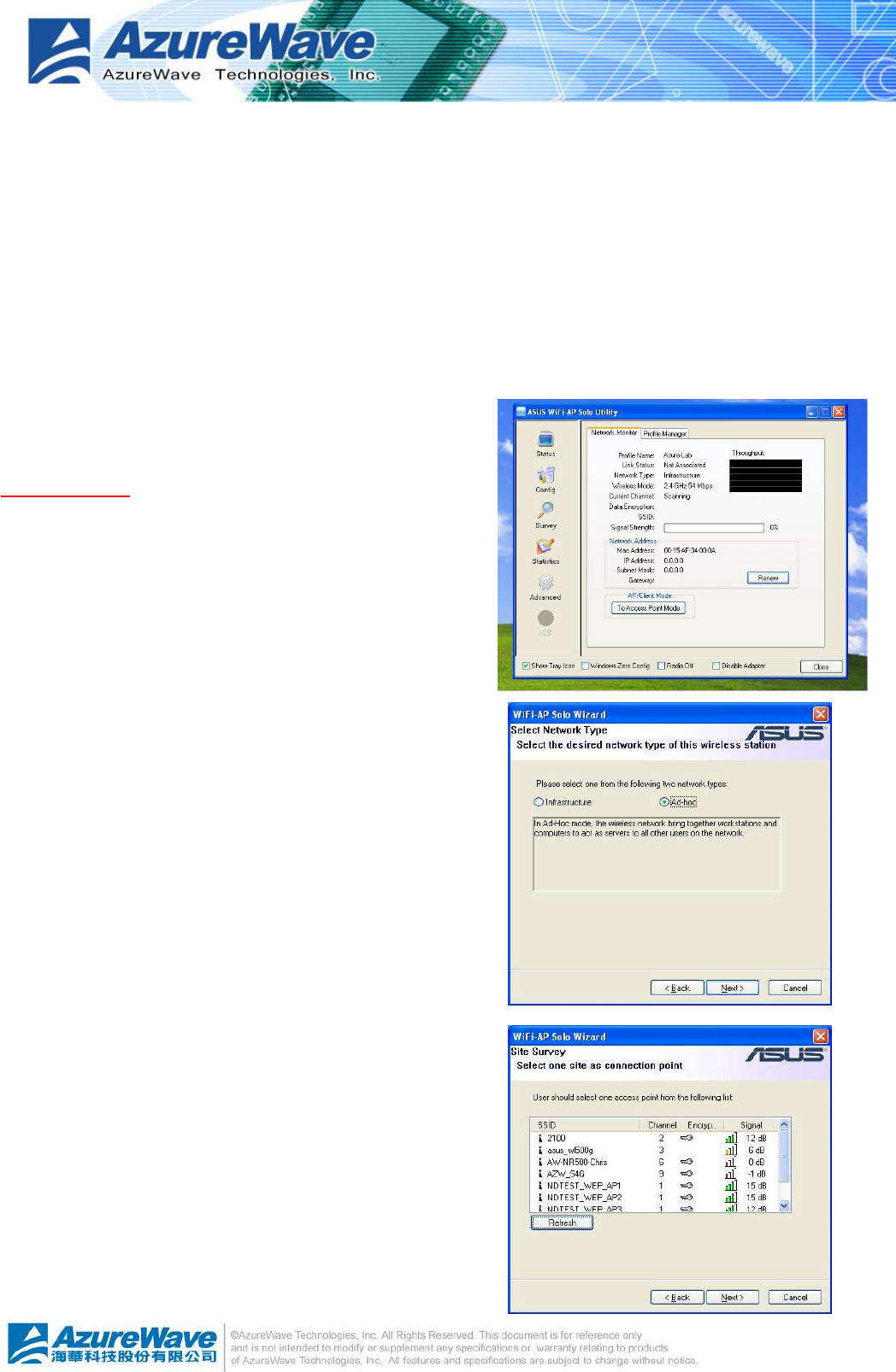
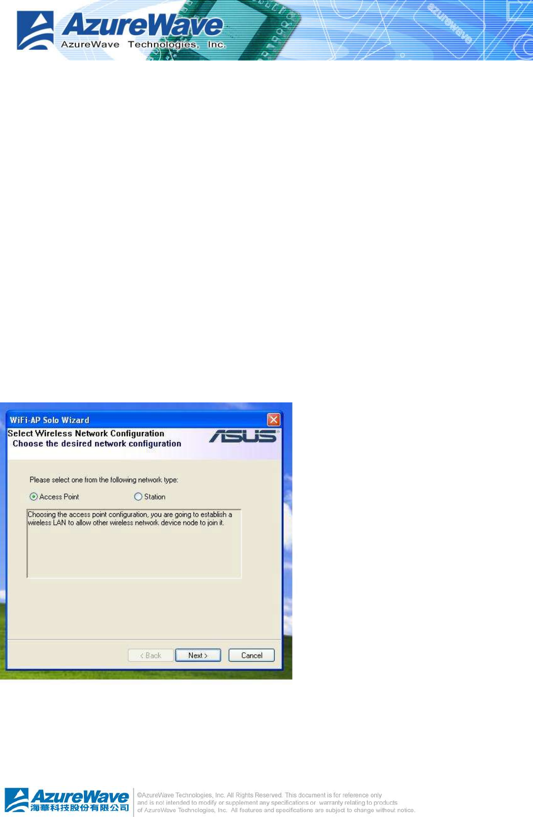
3.2 Wi-Setup Wizard Steps
Whatever which wireless configuration you would set up,
the first scene of WiFi-AP Solo Wizard is “Select
Operation Mode” dialog that shows as right picture. You
could select either station or AP mode from the first step.
For Ad-hoc and infrastructure type configuration, you
should select Station mode. The software access point
configuration could be archived by select AP mode.
l Station
Set the operation mode to be “Station”. Follow steps
in section 4.3.
l AP
Set the operation mode to be “Access Point”. Follow steps in section 4.4.
l Next
Go to next step of selected mode.
l Cancel
Give up WiFi-AP Solo Wizard. The default wireless configuration will be automatically
applied as “Infrastructure” type of Station mode if user won’t set it up here.
3.3 Station Mode Configuration
Two types, infrastructure and ad-hoc types, of station mode are provided here.
l Infrastructure
Configure the wireless as infrastructure type network.
Follow steps in 4.3.1 Build Infrastructure type network.
l Ad-Hoc
Configure the wireless as Ad-Hoc type network. Follow
steps in 4.3.2 Build Ad-Hoc networking mode network
l Back
Go back to previous step – Select Operation Mode.
l Next
Go to next steps of selected type.
3
-
4
l Cancel
Give up WiFi-AP Solo Wizard and keep the last configuration.
3.3.1 Configure Infrastructure type network
It is easy to build up infrastructure type network with WiFi-AP Solo Wizard. The next step after
select infrastructure type network is to select the desired connection.
Select the BSS connection list
Select valid wireless BSS, Infrastructure Basic Service
Set, connection nearby your system for connecting.
The listed BSS are touchable access point around you.
You have to pick one from the list and go to next.
l SSID list box
Four fields are shown in the list box to provide
access point status.
n SSID: the name of access point
n Security: the security status of access point. None
means security/password is not necessary. WEP means the access point acquire security/password
to log in.
n Channel: the channel this access point applies.
n Signal: The signal strength; higher mean better.
l Refresh
Rescan the IBSS list.
l Back
Go back to previous step ~ Select Station
Type.Next
Go to next step of infrastructure type
configuration. It is relative the security status of
selected access point.
n None: Setup TCP/IP.
n WEP: A WEP dialog is pope dup before Setup
TCP/IP as below picture. You have to input the password/network key to join this access point
before setup TCP/IP. The password/network key is defined by the administrator of access point.
3
-
5
The invalid network key will stop going to next step.
l Cancel
Give up WiFi-AP Solo Wizard and keep the last configuration.
Setup TCP/IP
You have to setup the TCP/IP by following the configuration of connect access point. The
following setting should match the configuration of access point you join. Please check the
setting of it.
l Back
Go back to previous step ~ Select the IBSS connection list
l Finish
All settings of infrastructure are finished.
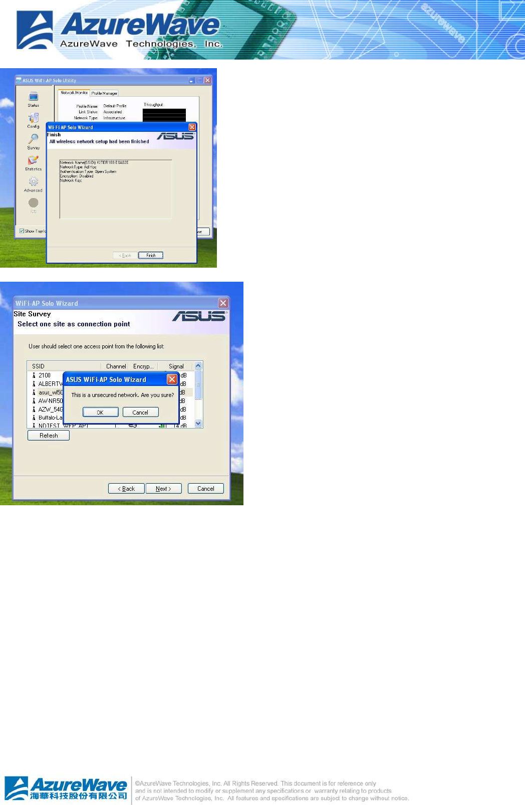
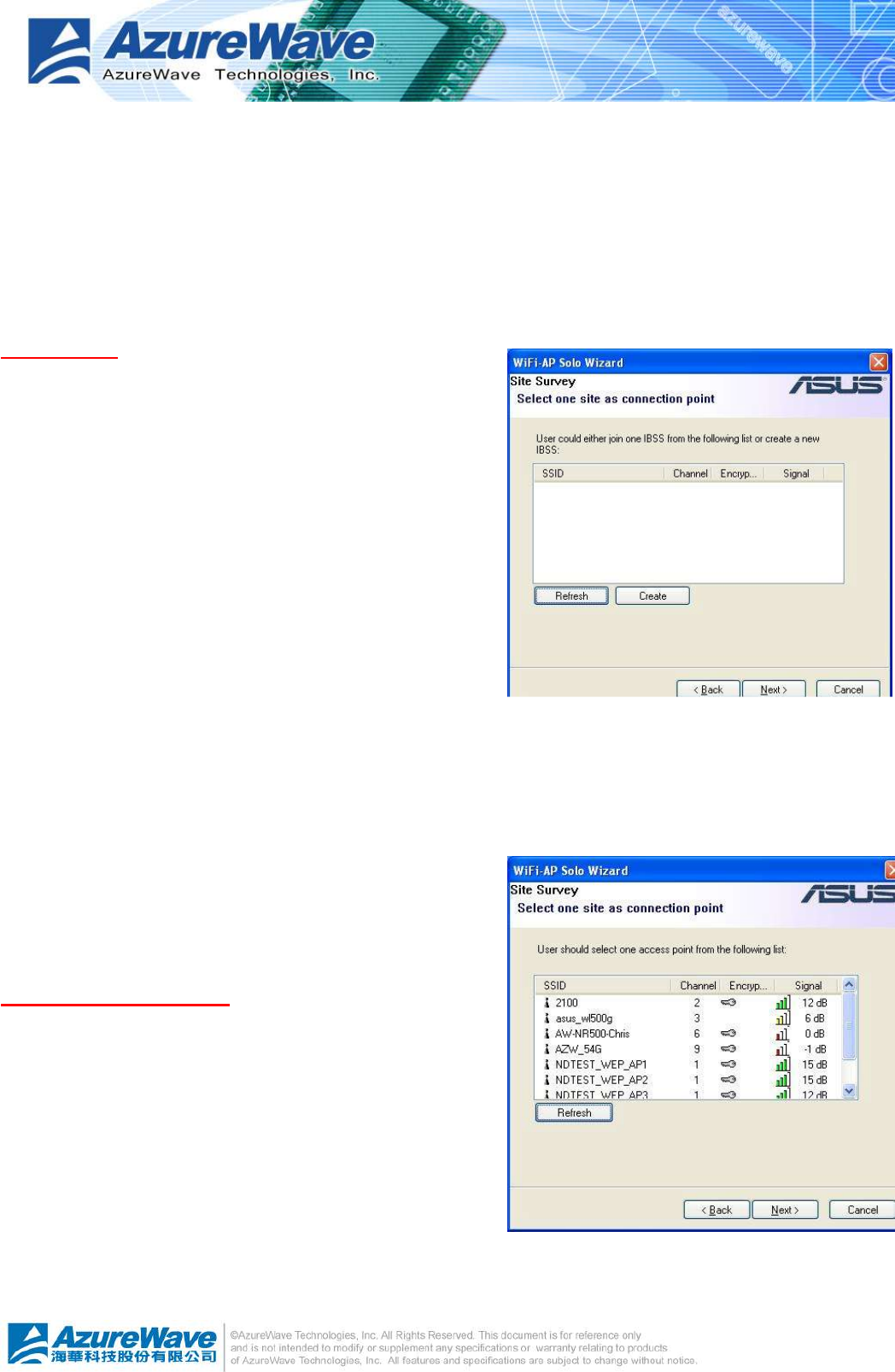
3.3.2 Build Ad-Hoc networking mode network
It is easy to build up Ad-Hoc type network with WiFi-AP Solo Wizard. The next step after select
Ad-Hoc type network is to select the desired connection.
Select The IBSS Connection List
In this step, you could select the present Ad-Hoc station to join. In addition, you could create
another Ad-Hoc station by press “New IBSS” button.
l SSID list box
Display all present Ad-Hoc station around this system.
3
-
6
l New IBSS
Create a new Ad-Hoc station by the
shown-up dialog instead of joining with a
present Ad-Hoc node. In this dialog, you
could configure network name, applied
channel, authentication and encryption rule
on this Ad-Hoc node. After creating a new
Ad-Hoc node, the steps of build Ad-Hoc
network connection is finished.
l Refresh
Rescan the Ad-Hoc stations nearby this system.
l Back
Go back to previous step ~ Select Station Type.
l Next
The wizard will show up the contents of profile. You should set it up to match the security
configuration with selected Ad-Hoc station. Then the steps are finished.
l Cancel
Give up WiFi-AP Solo Wizard and keep the last
configuration.
3.4 Build Soft AP network
Setup a Wireless Network
The setting of Soft AP could settle done by Wife-AP Solo
Wizard.
3
-
7
Only basic settings are included in following steps. Less-experience users could apply this
kind setup to archive access point setup. Fundamental security setting is included.
l Back
Go back to previous step ~ Select Operation Mode
l Next
The next step is dependant on the option user select:
l Cancel
Give up current WiFi-AP Solo Wizard setup and roll back to previous configuration.
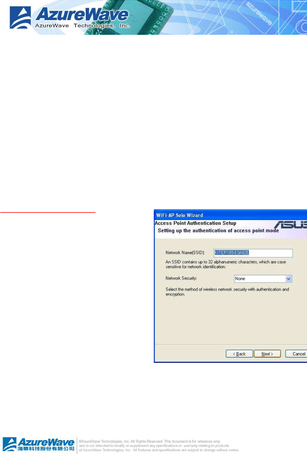
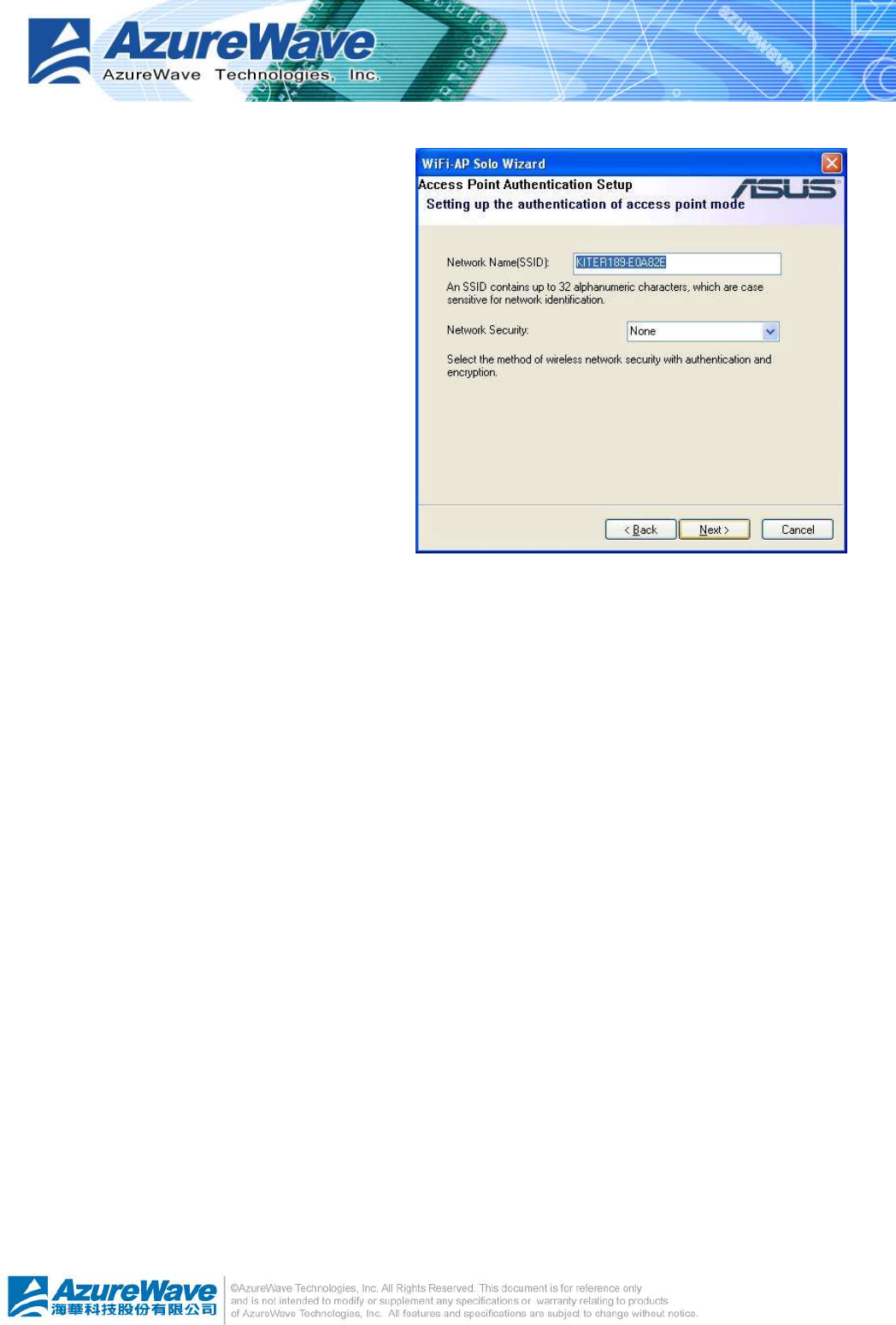
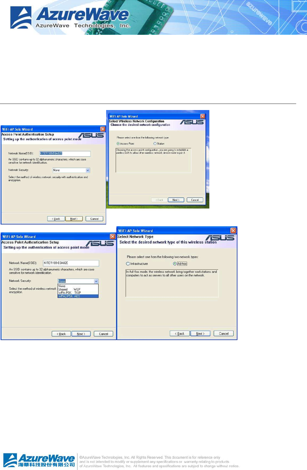
3.4.1 Software AP setting
For Software AP mode, the basic security function only request two types network/password
key to provide WEP encryption.
Wireless Network Properties
l Network Name (SSID)
The service serve identify of this access
point. The length of the self-naming does
not exceed 32 characters.
l WEP Encryption
n Enable: The joined wireless station should
have same network/password key with this
access point.
n Disable: no network/password key is
required for joined wireless station.
l Back
Back to previous step ~ Setup a Wireless
Network
l Next
The next step is dependant on the decision of WEP to be either Enable or Disable.
n WEP Enable: You should prepare network/password key for WEP. Go to Wireless Network Security.
n WEP Disable: The access point is set as an opened hot-spot. Anyone could join this access point
and connect to internet.
3
-
8
l Cancel
Give up current WiFi-AP Solo Wizard setup and roll back to previous configuration.
Wireless Network Security
Two types pass key, ASCII and Passphrase,
perform security with different level.
l ASCII
You should provide either 5 or 8 ASCII
characters on Network key edit box.
l PASSPHRASE
You could input words on Network Key edit
box.
n 64 bits: The generated pass key is 64-bits to be
company with data packets.
n 128 bits: The generated pass key is 128-bits to
be company with data packets.
l Back
Go back to previous step ~ Wireless Network Properties
l Next
Go to next step ~ Show Setting Information
l Cancel
Give up current WiFi-AP Solo Wizard setup and roll back to previous configuration.
Show Setting Information
l Back
If you do not satisfy with current setting, you could go back to previous step ~ Wireless
Network Security
3
-
9
l Next
Confirm the current setting and go to
next step ~ Finish.
l Cancel
Give up current WiFi-AP Solo Wizard
setup and roll back to previous
configuration.
3
-
10
Select the Internet Connection List
This step only shows with multiple network
connection system. If there is only one
internet connection available, this step is
discarded. In this step, you have to select
one network connection from the list box.
This network connection should be
configured to connect internet.
l Network List Box
In the list box, you could see all network
connection this system provides. You
have to pick one from the list.
l Back
Go back to previous step ~ Show Setting Information.
l Next
Go to next step, Finish, while the internet connection is selected.
If the status of selected network connection is disconnected, a warning dialog will pop up
to inform you that.
l Cancel
Give up current WiFi-AP Solo Wizard setup and roll back to previous configuration.
3
-
11
Finish
l Finish
Press finish button to close WiFi-AP
Solo Wizard. The wireless configuration
is going to be applied within few
seconds.
3.4.2 Advanced User
The steps of advanced user provide more
detail configuration including channel and
authentication
Wireless Network Properties
In this step, you could assign the channel
number and authentication mode for the
access point.
If the setting of WEP to be “Disable” and
Authentication to be “Open system”, then
this access point is opened for free join.
l Network Name (SSID)
The service serve identify of this access point. The length of the self-naming does not
exceed 32 characters.
l Channel select
You could pick one channel from 1 to 11.
l WEP Encryption
An encryption system prevents eavesdropping on wireless network traffic.
3
-
12
n Enable: The joined wireless station should have same network/password key with this access
point.
n Disable: no network/password key is required for joined wireless station.
l Authentication
The next generation of Wi-Fi security, Wi-Fi Protected Access, or WPA, will use
authentication to verify whether users have access to a particular wireless network.
n Open system: This access point is without authentication protection with user.
n Share key: Any station would join this access point should pass with key same as the setting on
access point.
l Back
Go back to previous step ~ Setup a Wireless Network.
l Next
Go to next step. It depends on the setting of WEP and Authentication.
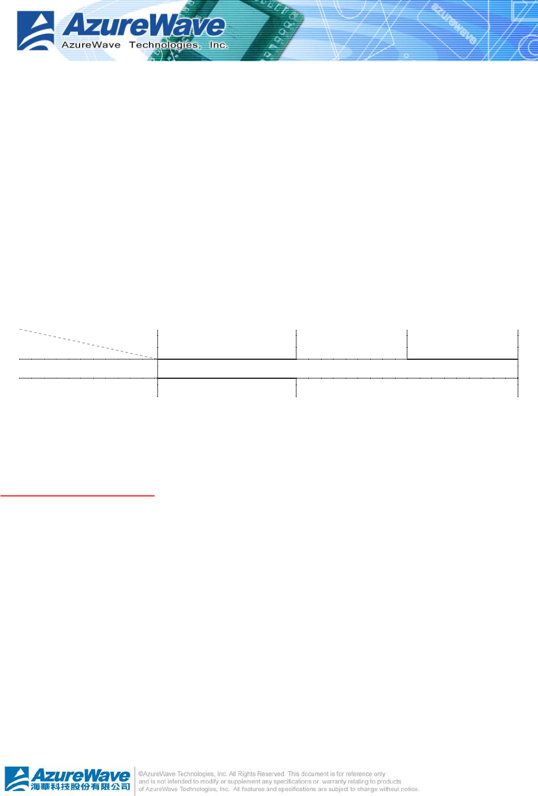
Authentication
Encryption Open system Shared key WPA-PSK
WEP WLAN Security
WEP(Disable) Show Network Setting
n/a
l Cancel
Give up current WiFi-AP Solo Wizard setup and roll back to previous configuration.
Wireless Network Security
Two types pass key, ASCII and Passphrase, perform security with different level.
l ASCII
You should provide either 5 or 8 ASCII characters on Network key edit box.
l PASSPHRASE
You could input words on Network Key edit box.
n 64 bits: The generated pass key is 64-bits to be company with data packets.
n 128 bits: The generated pass key is 128-bits to be company with data packets.
l Back
Go back to previous step ~ Wireless Network Properties
l Next
3
-
13
Go to next step ~ Show Setting Information
l Cancel
Give up current WiFi-AP Solo Wizard setup and roll back to previous configuration.
Show Setting Information
l Back
If you do not satisfy with current setting, you could go back to previous step ~ Wireless
Network Security
l Next
Confirm the current setting and go to next step ~ Finish.
l Cancel
Give up current WiFi-AP Solo Wizard setup and roll back to previous configuration.
Select the Internet Connection List
This step only shows with multiple
network connection system. If there
is only one internet connection
available, this step is discarded. In
this step, you have to select one
network connection from the list box.
This network connection should be
configured to connect internet.
l Network List Box
In the list box, you could see all
network connection this system
provides. You have to pick one
from the list.
l Back
Go back to previous step ~ Show Setting Information.
l Next
Go to next step, Finish, while the internet connection is selected.
l Cancel
Give up current WiFi-AP Solo Wizard setup and roll back to previous configuration.
3
-
14
Finish
l Finish
Press finish button to close WiFi-AP Solo
Wizard. The wireless configuration is going to
be applied within few seconds.
4
-
1
Chapter 4 AsusWLAN: Wireless LAN Management
GUI
4
-
2
4
-
3
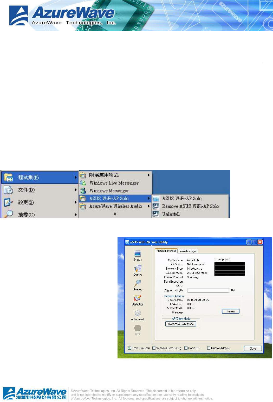
4.1 How to Launch AsusWLAN
You could launch AsusWLAN from either Windows® Program Menu or tray icon. The tray icon
is an optional quick launch to be enabled by user.
Windows® Program Menu
It is the absolute way to launch AsusWLAN from program folder.
Tray Icon
The tray icon will not be show
until you enable the “Show Tray
Icon” from AsusWLAN as the
right picture. As the AsusWLAN
icon shown on system tray, you
could double click the icon with
mouse button to launch it.
4.2 Introduction of Main Window
The main window is assembled with five parts, main menu, adapter list area, properties area,
global control bar and status bar. Please read the explanations below before operating the
AsusWLAN.
4
-
4
Main Menu
The main menu includes five submenus.
l Refresh
As clicking the refresh menu, the contents of adapter list area are re-enumerated and
updated.
l Set up Wizard
Quickly launching the WiFi-AP Solo
Wizard. The convenient quick
launching helps you to reprogram the
wireless configuration as need.
4
-
5
l Adapter List Area
This area displays all connected adapters on this system for mutiple adatper installations.
The easy switch helps user to change the selected adapter by one click. The contents of
properties area are dependant on wireless configuration that the selected adapter was set
up. For single adatper installed system, the only one adapter is always selected.
l Properties Area
The contents of this area are dependent on
current wireless configuration. You could know
the current configuration through previous
explanation of submenu “Mode”. The detail
contents are described in following wireless
configuration sections for both Station and AP
mode.
4
-
6
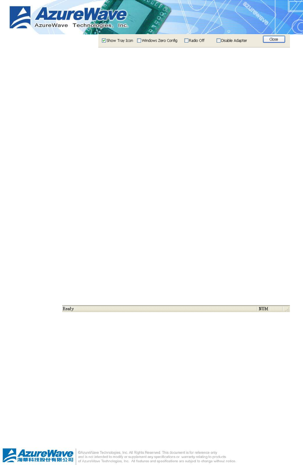
l Global Control Bar
Each control items on this
bar affects the adapter or management GUI directly.
n Show Tray Icon
Making this item to be checked, the management GUI will minimize and stay on the
tray icon located at the right down corner of Windows while pressing “Close” button. In
other word, management GUI will shut down while pressing “Close” button with
unchecked condition.
n Windows Zero Config
Help switching to Microsoft Windows ® XP Wireless network configure service if you do
not prefer applying AsusWLAN as your wireless LAN manager. The detail steps you
should follow are described in section 4.5.
n Radio Off
Turn off the radio for saving power. While the radio being off, the links with other
wireless network nodes are disconnected. User should be care of it while the wireless
configuration is in AP mode. The radio off will cause the sub network belong to the AP
to disconnect with internet/intranet.
n Disable Adapter
Make this wireless LAN adapter being functionless for increasing better system
resource management on performance and CPU utilization.
n Close
Shutdown or hide the management GUI. The behavior depends on the check box of
“Show Tray Icon”.
l Status Bar
The status bar presents the hints or status of the management GUI.
4.3 Station mode
Two types, Ad-Hoc and infrastructure in station mode could be configured through WiFi-AP Solo
Wizard. The following two sections explain the operation of management GUI for each type.
The following explanations focus on the properties area.
4
-
7
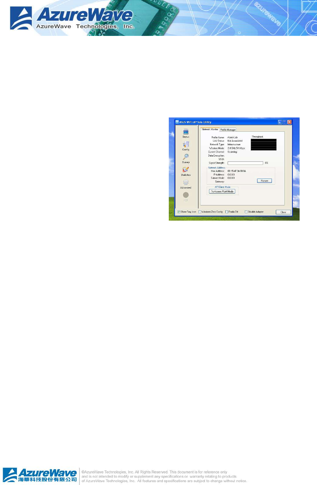
4.3.1 Infrastructure and Ad-Hoc
With both Infrastructure and Ad-Hoc types, the properties should looks like the picture beside.
Six property pages present different information of current wireless network status.
Reading the following explanations before you reviewing these pages, it could help you to well
know the wireless environment around the system.
It is easy use to switch property pages just by left button clicking of mouse the title of each page
The following six sections describes detail
information of the opposite page.
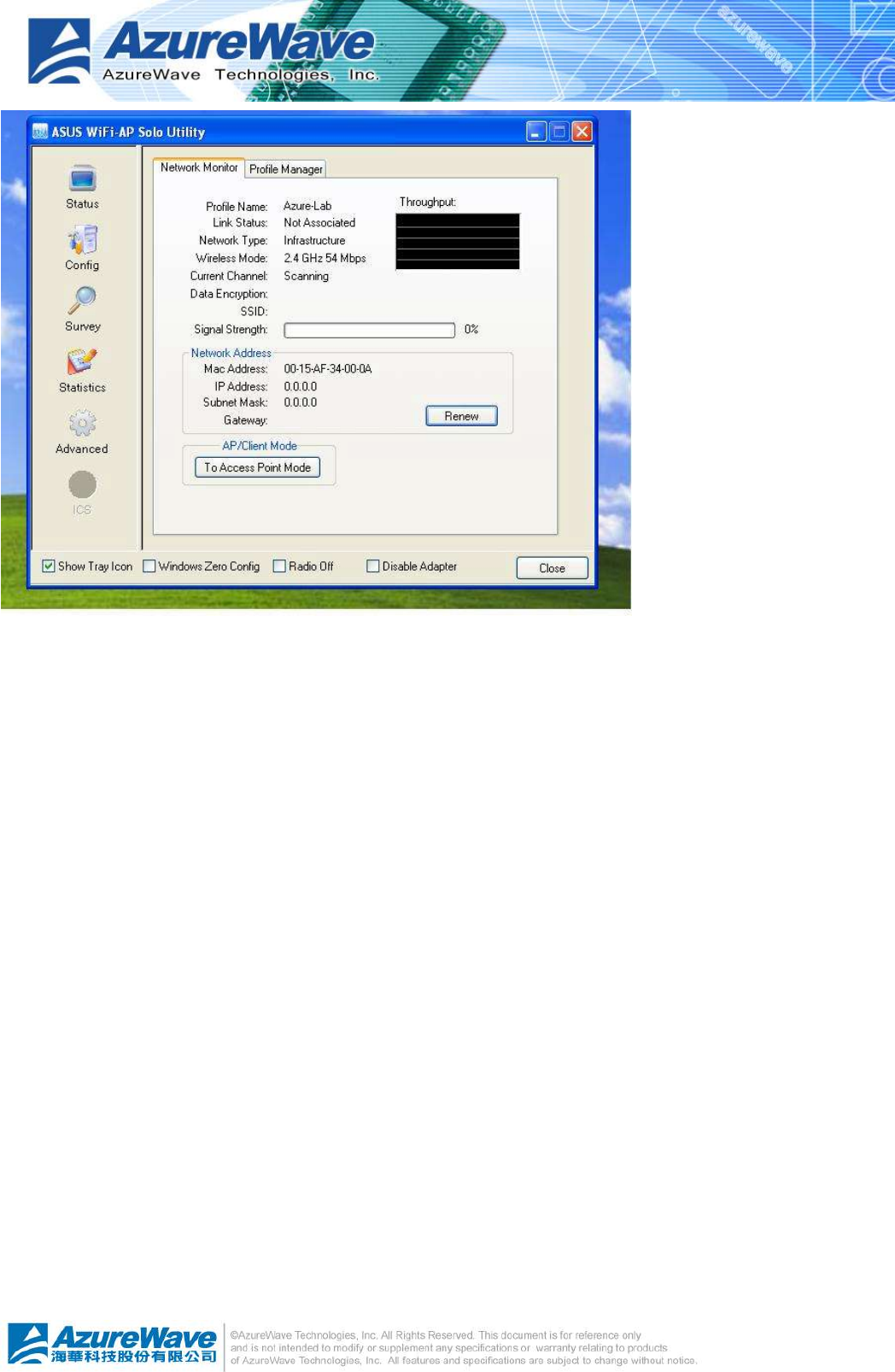
General page
This page represents the general information of this
adapter.
l Status
The connection status with access point this
station has.
l Speed
Current transition speed in
Mbps.(Mega-Bits-Per-Second)
l Type
Current wireless LAN configuration type
l Encryption
Current encryption mode used
l SSID
Name of wireless network
l Signal Strength
The average quality of signal pf packets received
from wireless network. We recommend
connecting access point with over 70% signal
strength.
l Throughput diagram
Transition (Tx) performance
4
-
8
l Network Address group
n Mac Address: six two-digital number of this adapter
n IP Address: assigned network address by DHCP server or self-definition in four three-digital
number format
n Subnet Mask: the only valid value is 2555.255.255.0
n Gateway: It comes from connected access point. Your system can not connect internet with this
field empty.
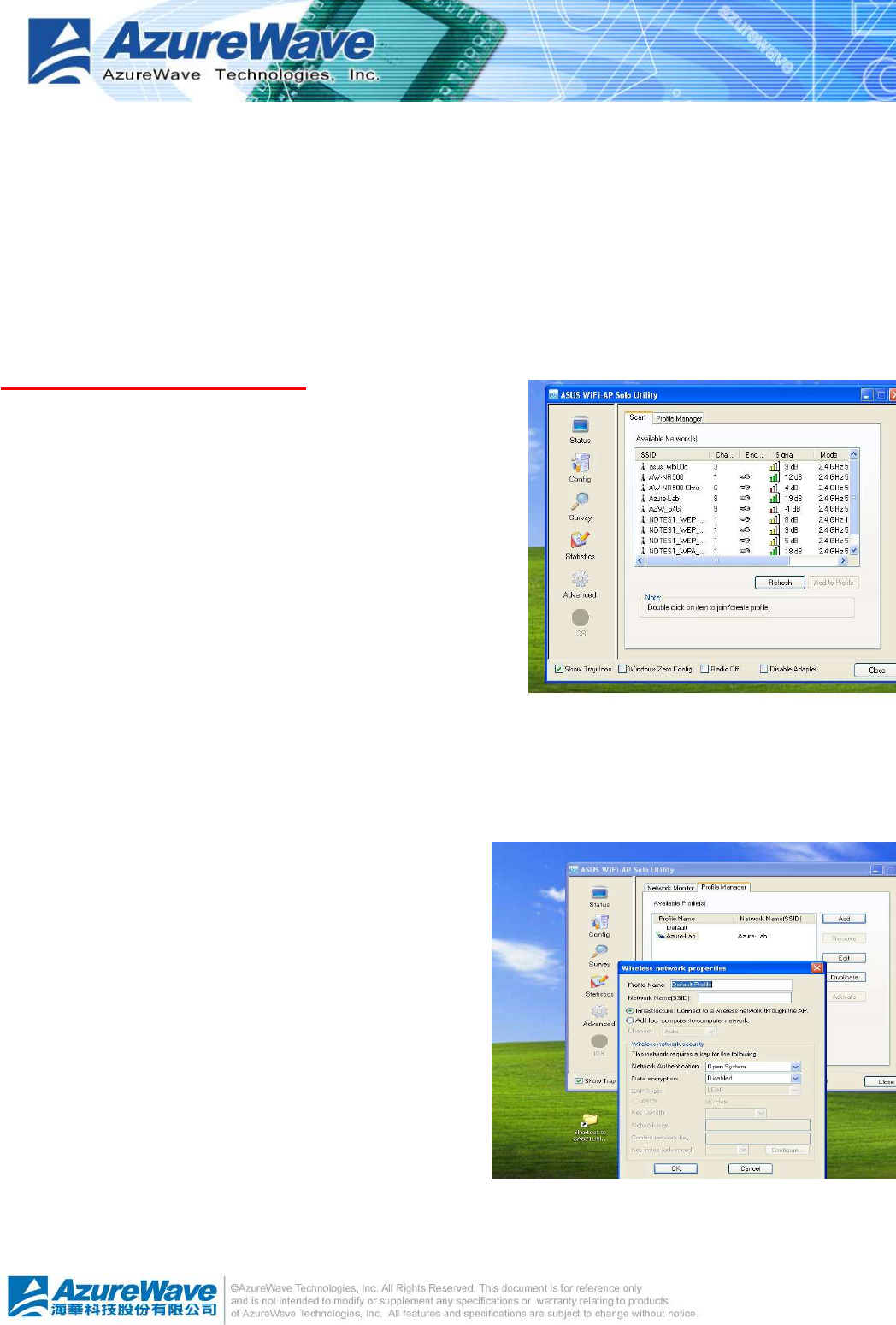
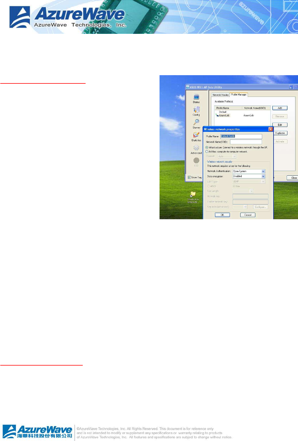
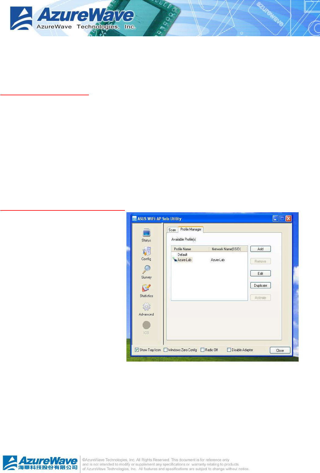
Profile page
This page provides profiles management like add,
remove, edit and duplicate just by pressing the
button.
l Available Profile(s)
The list box shows all the created profiles.
l Add
Add a new access point profile by manual input.
l Remove
Remove the selected profile
l Edit
Edit contents of selected profile
l Duplicate
Make copy of selected profile.
l Set Default
Set the selected profile as default selection.
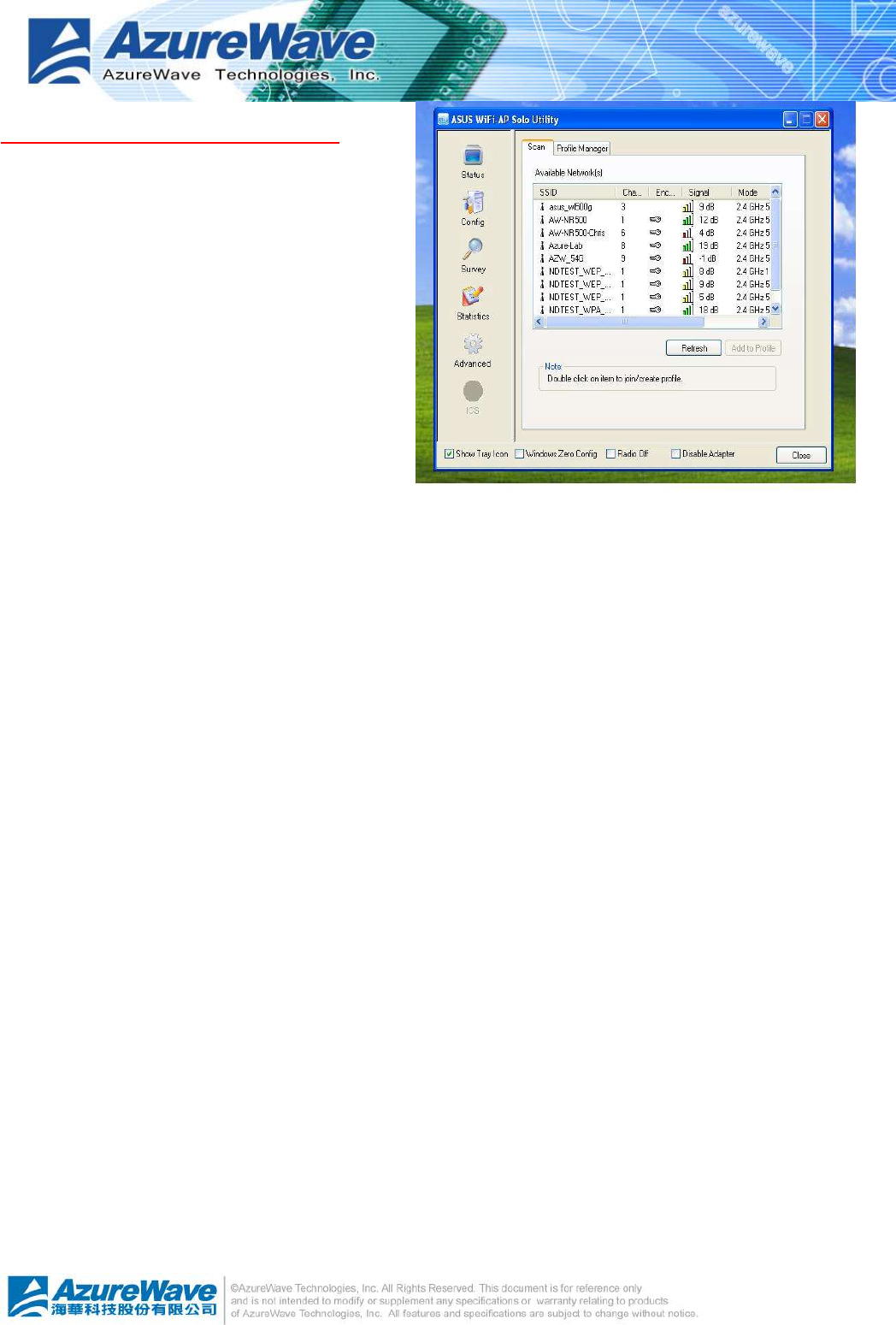
Available Network page
This page presents all access points around this
system. And you could pick one of these network
connections.
l Available Network(s)
Present network connection around this system
l Refresh
Rescan network connection around this system
l Add to Profile
4
-
9
Create profile for selected network connection in profile list and add it in to profile list.
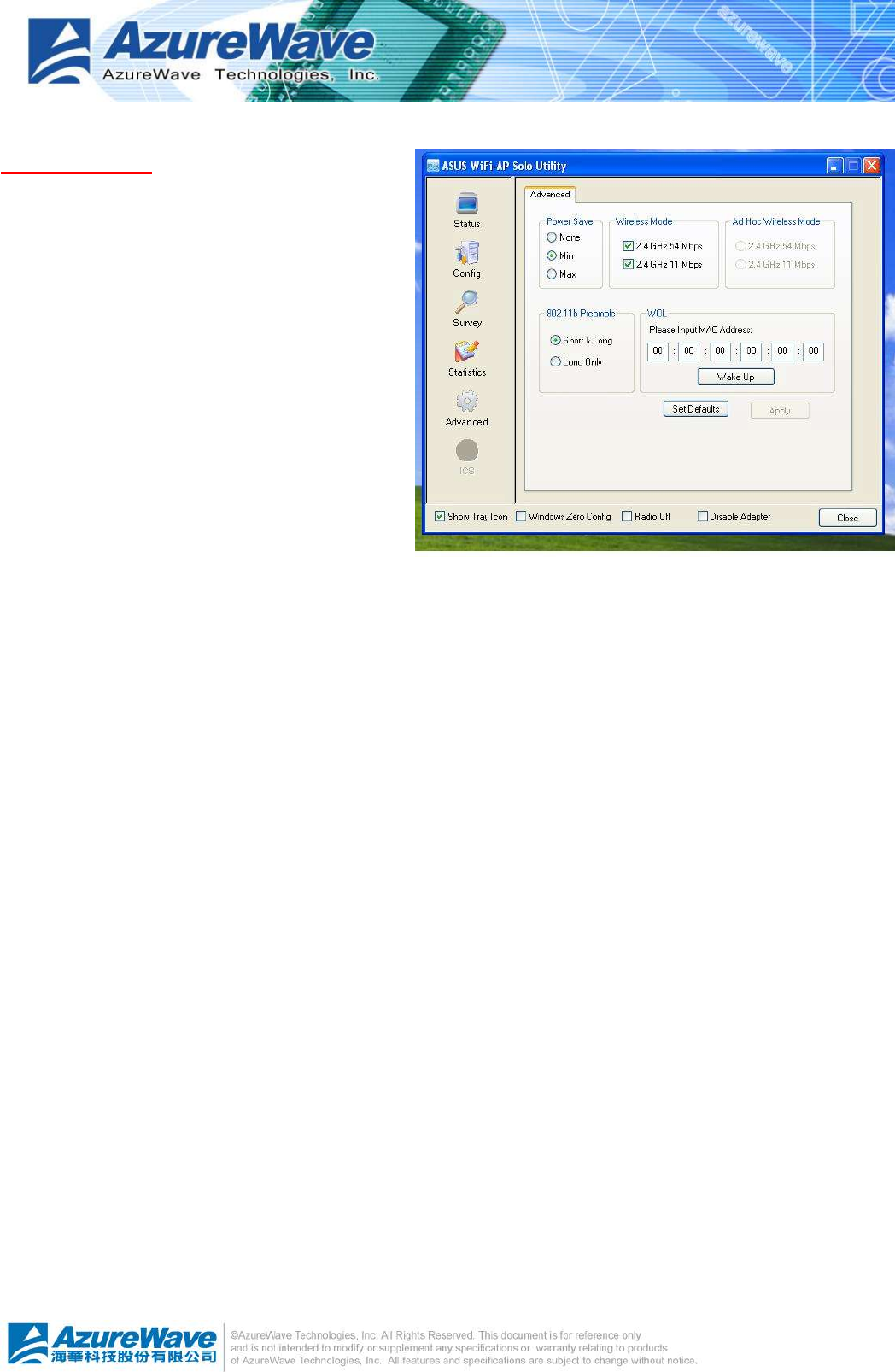
Advanced page
l Power Save
n None: without power save mode
n Min: wake up every two time interval to
receive packets
n Max: wake up every ten time interval to
receive packets
l Wireless Mode
n 802.11b
n 802.11g/b
l 802.11b Preamble Mode
n Long: higher quality but with lower
performance than preamble short mode
n Short: Normal quality but with higher performance then preamble long mode.
n Auto: select the proper preamble mode by current signal frame information.
l Fragment Threshold
The threshold of fragment length. Higher threshold increase data transition performance
with good signal quality. Pool signal quality results more worst data throughput on high
fragment threshold.
l RTS Threshold
Request to send threshold. The request will not send out until the accumulated data over
threshold.
l WOL (Wake On LAN)
The wake-on-LAN is applied for remote control purpose. You could wake up a system
through network packets. For AzureWave802.11 b/g PCI Express WLAN Module, only the
same adapter on another system could wake it up.
n Input MAC Address: the six two-digit numbers of AzureWave802.11 b/g PCI Express WLAN Module
on target system.
n Wake Up: press this button to wake it up
l Set Defaults
Restore the default value to be current setting
l Apply
Apply the current setting to GUI
4
-
10
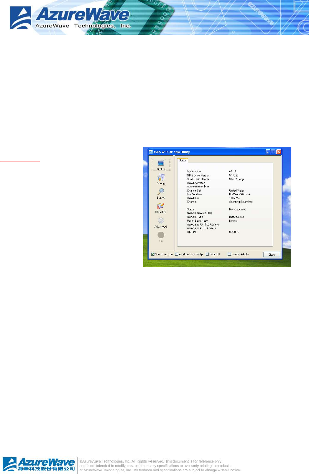
Status page
l Manufacturer: It always is Atheros.
l NDIS Driver Version:
l Short Radio Header
l Encryption: Current encryption mode.
l Authenticate: authentication state
l Channel Set: selected channel plan
currently. Please reference Appendix-A
with the detail comparisons.
l MAC Address: MAC address of this
adapter.
l Data Rate: wireless LAN transition speed
l Channel(Frequency): current channel number
l Status: wireless network status
l SSID: name of connecting access point
l Network Type: indicate current network configuration type
l Power Save Mode: current setting power save mode
l Associated AP MAC: MAC address of connecting access point
l Associated AP IP: IP address of connecting access point
l Up Time: total connection time
4
-
11
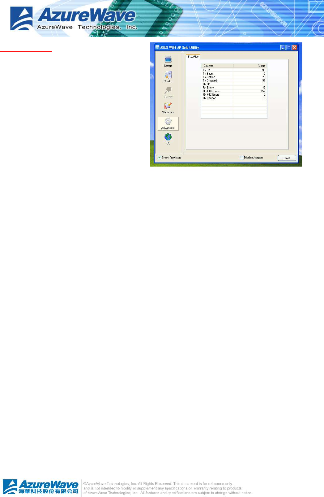
Statistics page
You could watch the Tx/Rx status of current
wireless connection. It provides a statistic
analysis of packet transition.
4
-
12
4.4 AP mode
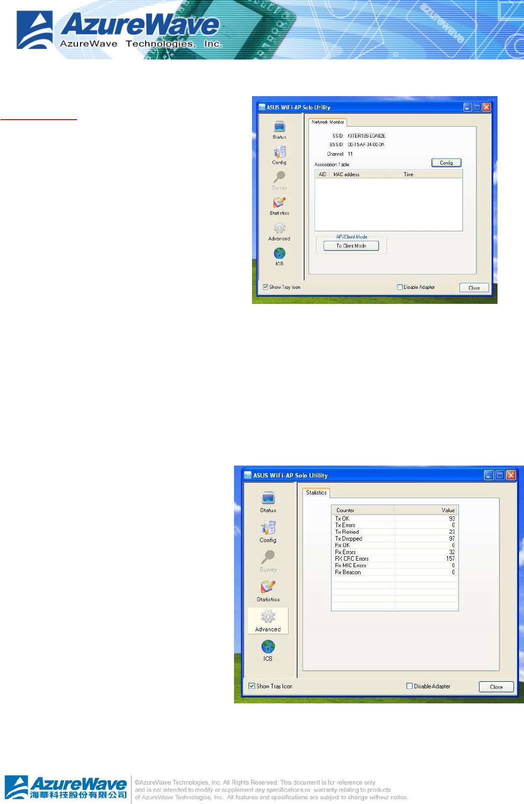
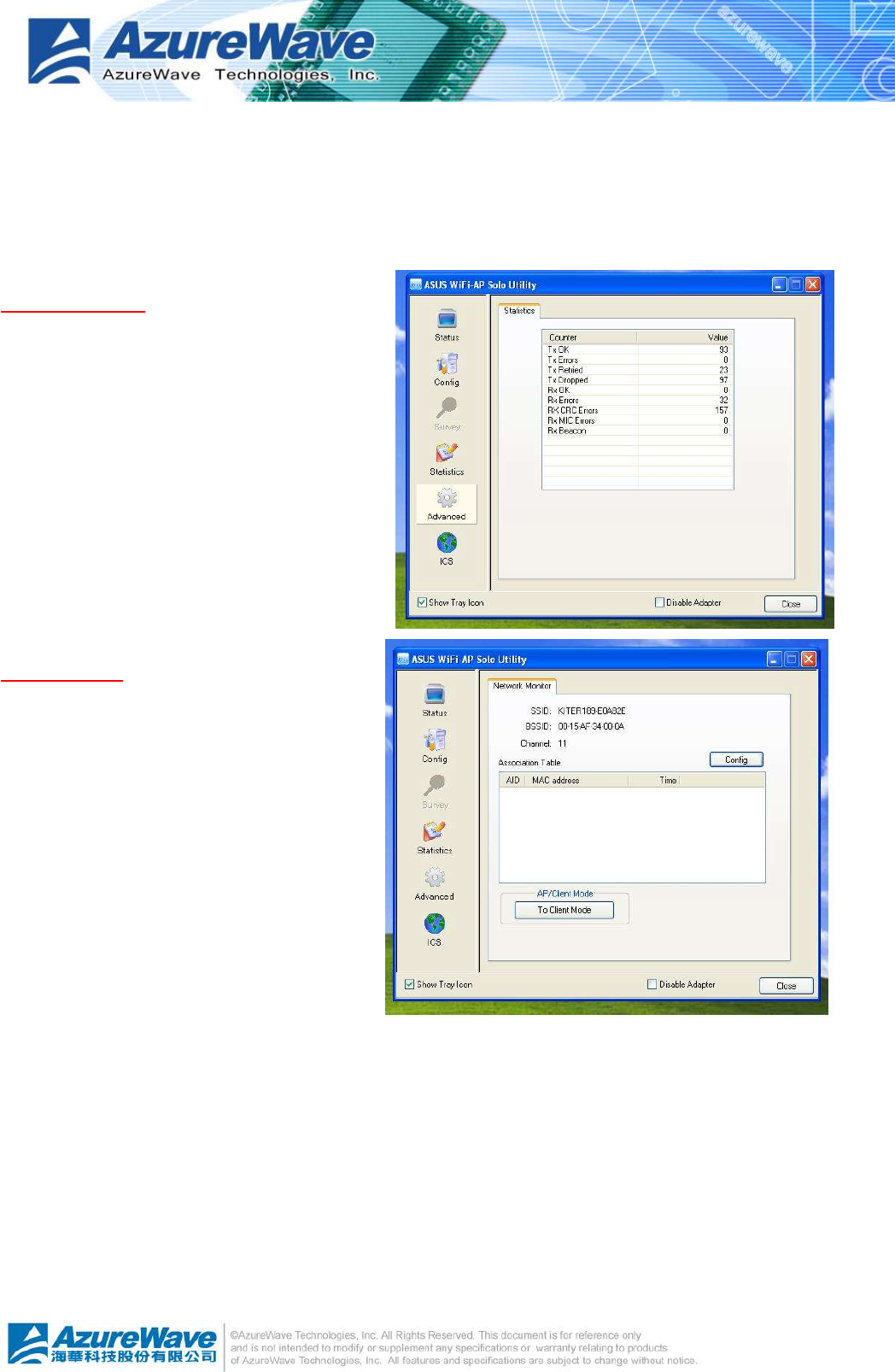
General Page
In this page, it provides general information
of this access point including name, MAC
address and list of joined stations.
l SSID
The name of this access point is.
l BSSID
Six two-digital numbers configure the
MAC address of this access point.
l Association Table
It is the list of joined station on this access point.
n AID (Association ID)
The AID field is a value assigned by an AP during association that represents 16-bit ID of
a station. It is a unique value assigned by AP.
n MAC address
It is the six two-digit numbers that assemble the MAC address of joined station.
n Life Time
It is timer and counts down from
10 minutes whenever the access
point connects the station
successfully.
l Config
A dialog of this access point is shown
up for configuration modification
except by WiFi-AP Solo Wizard.
n Network Name (SSID)
Name of the access point
searched by other wireless nodes.
The length of SSID should be
shorter than 32 characters.
n Channel
Select the wireless channel within current channel plan.
4
-
13
n Network Authentication & Data Encryption
Three types authentication:
¦ Open System
It is combined with data encryption type to be WEP or disable.
Encryption ~ disabled: you decide to open this access point to every one without network
authentication.
Encryption ~ WEP: you decide to setup the basic data encryption with a defined network key.
¦ Shared Key + WEP
You decide to apply both authentication and data encryption to prevent illegal login.
¦ WPA-PSK + TKIP
The most advance authentication and data encryption could provide best security protection.
n ASCII
You should provide either 5 or 13 ASCII characters on Network key edit box.
n PASSPHRASE
You could input words on Network Key edit box.
¦ 64 bits: The generated pass key is 64-bits to be company with data packets.
¦ 128 bits: The generated pass key is 128-bits to be company with data packets.
n Hexadecimal
While both ASCII and PASSPHRASE are not checked, you should input hexadecimal
number in the network key box.
n Key index (1 ~4)
At most four key index to represent the opposite network key.
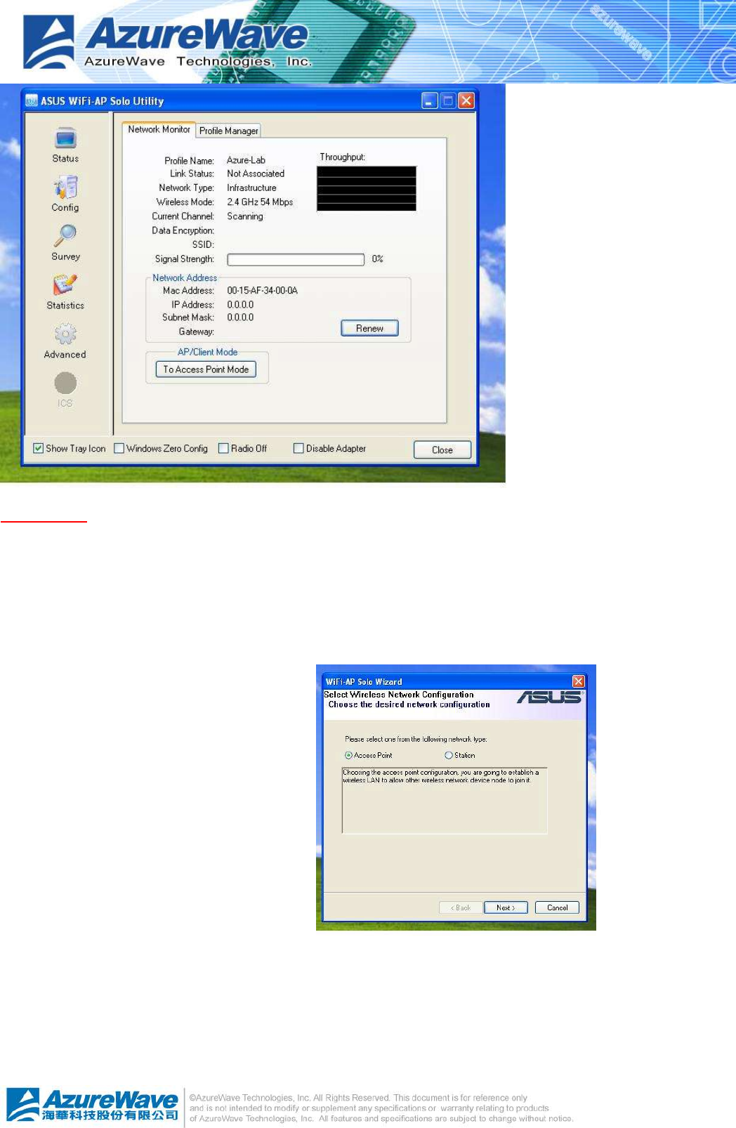
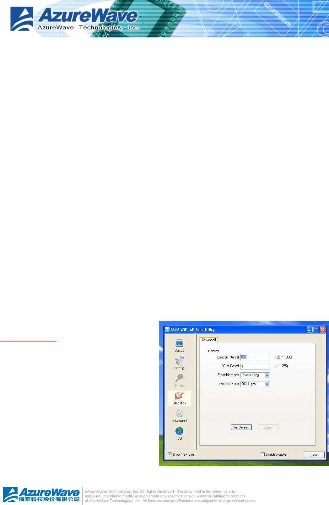
Advanced Page
In this page, expert could setup the advance
characteristics of network packet on
transmission.
l Beacon Interval
This filed represents the interval between
each beacon that this AP sends out.
Longer interval may increase the
competition of wireless nodes. The
maximum value of it is
l DTIM Period
The DTIM Period field indicates the number of Beacon intervals between successive DTIMs.
4
-
14
l Preamble Mode
n Long: higher quality but with lower performance than preamble short mode
n Short: Normal quality but with higher performance then preamble long mode.
n Auto: select the proper preamble mode by current signal frame information.
Statistics Page
You could watch the Tx/Rx status of
current wireless connection. It provides a
statistic analysis of packet transition.
SoftAP Page
l ConnName list box
List all network connections on this
system. You should pick up one from
the listed item(s) if you would
connect the network domain, created
by Soft AP, to internet/intranet
network.
l Select
Pick up the desired network
connection to public network.
l Apply
Execute the current setting.
4
-
15
4.5 Windows Zero Configuration
The Windows Zero Configuration is a wireless LAN service that does not provided by Microsoft
Windows® until Windows XP. It provides basic and easy on connecting the wireless network. In
this chapter, we introduce you the steps to swap between Windows Zero Configuration and
AsusWLAN. If you prefer Windows Zero Configuration instead through AsusWLAN, then you
should follow the steps in 4.5.1 to switch to Windows Zero Configuration. In addition, you could
rollback to AsusWLAN by following the steps in 4.5.2.
4.5.1 Swap from AsusWLAN to Windows Zero Configuration
Five steps are required to archive this operation as following:
Windows Zero Configuration is disabled after installing AsusWLAN. You should enable it by
making the “Windows Zero Config” item being checked on global control bar. And then a Zero
Config dialog is shown up to inform you. Then you have to press OK to confirm the translation.
4
-
16
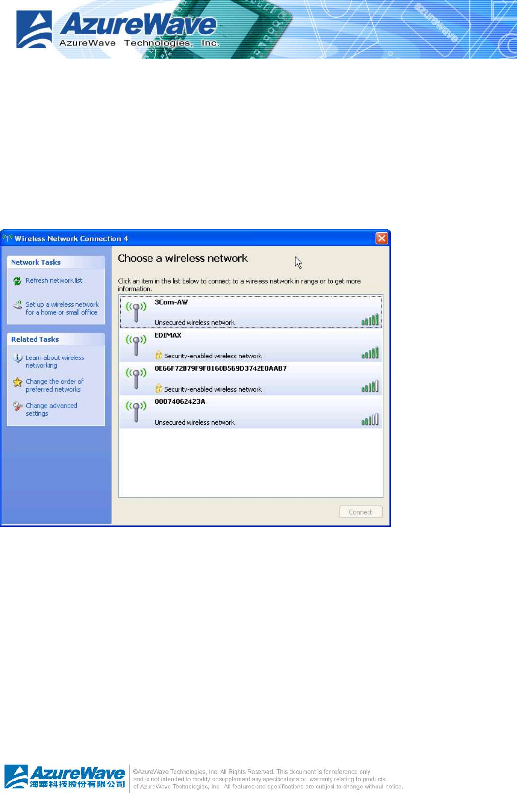
After opening the page of present wireless network, if you see the scene similar to the following
figure, then you had been swapped to Windows Zero Configuration successfully. Otherwise,
you should check and repeat the previous steps again.
4.5.2 Rollback from Windows Zero Configuration to AsusWLAN
If you prefer the AsusWLAN instead of Microsoft® Windows Zero Config, please follow the
steps to rollback. Open AsusWLAN, make the “Windows Zero Config” item on global control bar
to be unchecked. After a while, the property area starts to display network connection.
4
-
17

4
-
1
Appendix A: Mapping of country and channel plan
Channels
Country Channel Set
1~11 Argentina ,Brazil ,Canada ,Colombia ,Mexico ,Taiwan ,United States of
America,Yugoslavia FCC,IC,TAIWAN
1~13
Australia ,Austria ,Bahrain ,Belarus ,Belgium ,Bolivia ,Bulgaria ,Chile ,China ,Co
sta Rica ,Croatia ,Cyprus ,Czech
Republic,Denmark ,Egypt ,Estonia ,Finland ,France2 ,Germany ,Greece ,Hong
Kong,Hungary ,Iceland ,India ,Indonesia ,Ireland ,Italy ,Kuwait ,Latvia ,Lebanon ,
Liechenstein ,Lithuania ,Luxembourg ,Macedonia, The Former Yugoslav
Republic of ,Malaysia ,Morocco ,Netherlands ,New
Zealand,Nigeria ,Norway ,Panama ,Paraguay ,Peru ,Philippines ,Poland ,Portug
al ,Puerto Rico,Romania ,Russia ,Saudi
Arabia,Singapore ,Slovakia ,Slovenia ,South Africa,South
Korea,Sweden ,Switzerland ,Thailand ,Turkey ,United Arab Emirates,United
Kingdom ,Uruguay ,Venezuela
ETSI,MKK1
10 ~ 13 France,Jordan France
3~9 Isreal Isreal
1~14 Japan1 MKK1+MKK
14 only Japan2 MKK
10~11 Spain Spain
4
-
2
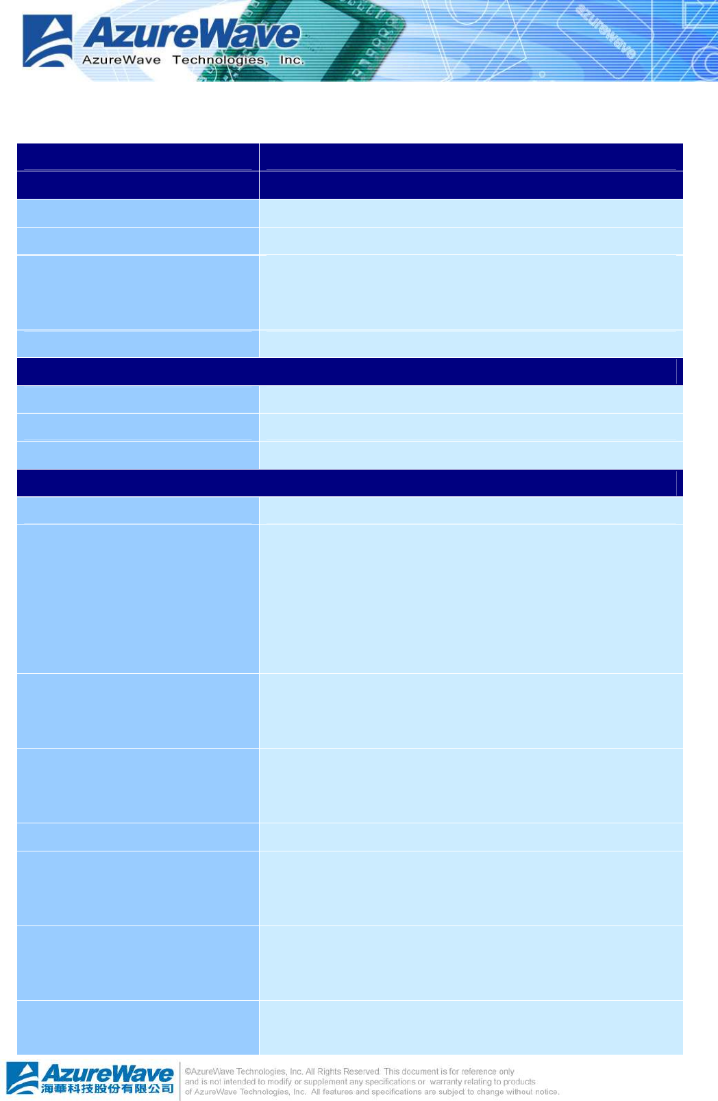
General Specifications
Model Name AW-GA821
Product Description PCI Express Wireless Module
WLAN Standard IEEE 802.11b/g, Wi-Fi compliant
Host Interface PCI Express 1.0a
Dimension
35mm x 80mm x 11.7mm
(not including SMA connector and pin headers)
Weight 15 g
Operating Conditions
Voltage 3.3V +/- 5%
Temperature Operating: 0 ~ 55oC; Storage: -20 ~ 65oC
Humidity 15% ~ 95%
Electrical Specifications
Frequency Range 2.4 GHz ISM radio band
Number of Channels
802.11b: USA, Canada and Taiwan – 11 (2412~2462MHz)
Most European Countries – 13, France – 4, Japan – 14
802.11g: USA, Canada and Taiwan– 11 (2412~2462MHz)
Most European Countries – 13, Japan – 14
Modulation
802.11b: CCK(11, 5.5Mbps), DQPSK(2Mbps), BPSK(1Mbps)
802.11g: OFDM
Output Power
802.11b: typical 16 dBm +/-1.5dBm (Average power)
802.11g: typical 13 dBm +/-1.5dBm(Average power)
Antenna RSMA connector for external antenna
Receive Sensitivity
802.11b: typical -80dBm at 11Mbps
802.11g: typical -70dBm at 54Mbps
Data Rates
802.11b: 1, 2, 5.5, 11Mbps
802.11g: 6, 9, 12, 18, 24, 36, 48, 54Mbps
Power Consumption 802.11b: TX:720mA; RX:410mA at 3.3V

4
-
3
802.11g: TX:740mA; RX:440mA at 3.3V
Security u WEP 64-bit and 128-bit encryption
u WPA(Wi-Fi Protected Access)
Operating System Compatibility Windows ME/2000/XP/server 2003/64bit XP
Regulatory
FCC 47 CFR Part 15, Subpart C(Section 15.247), ANSI C63.4-2003
CE EN 300 328 V1.6.1/EN 50371
Taiwan LP0002
Australia AS/NZS 4268:2003
Canada RSS-210
Korea
China
Singapore
Malaysia
4
-
4
Appendix B: Q&A
Q:
After applying security setting, why my computer can not connect to the system that configures
the AzureWave802.11 b/g PCI Express WLAN Module as AP mode?
A:
There are several condition could result this issue.
l Security setting mismatch: please make sure the security and network key are identical to
both AP and station side.
l Station utilizes Windows Zero Configuration to join the Access Point: you could change the
WEP to be ASCII or Hexadecimal. The PassPhrase format is not supported by Windows
Zero Configuration.
Q:
My notebook cannot browse internet after connecting the AzureWave802.11 b/g PCI Express
WLAN Module. I could see the station on the general page of AsusWLAN. What’s happened?
A:
It could lose ICS connection. First, you should make sure the access point connect to
intranet/internet through another network connection. And then select the network connection
as ICS. Please reference the “Soft AP Page” segment in section 4.4.

4
-
5
Appendix C: Release History
Version
Comments Opposite Package Version
1.2 Update ICS operation of user interface
Add Appendix C for release history
10.27 ~
1.1 Update Windows Zero Configuration operations of user interface 10.27 ~
1.0 First formal release 09.27 ~

4
-
6
Federal Communication Commission Interference Statement
This equipment has been tested and found to comply with the limits for a Class B digital device,
pursuant to Part 15 of the FCC Rules. These limits are designed to provide reasonable
protection against harmful interference in a residential installation. This equipment generates,
uses and can radiate radio frequency energy and, if not installed and used in accordance with
the instructions, may cause harmful interference to radio communications. However, there is
no guarantee that interference will not occur in a particular installation. If this equipment does
cause harmful interference to radio or television reception, which can be determined by turning
the equipment off and on, the user is encouraged to try to correct the interference by one of the
following measures:
- Reorient or relocate the receiving antenna.
- Increase the separation between the equipment and receiver.
- Connect the equipment into an outlet on a circuit different from that
to which the receiver is connected.
- Consult the dealer or an experienced radio/TV technician for help.
This device complies with Part 15 of the FCC Rules. Operation is subject to the following two
conditions: (1) This device may not cause harmful interference, and (2) this device must accept
any interference received, including interference that may cause undesired operation.
FCC Caution: Any changes or modifications not expressly approved by the party responsible for
compliance could void the user's authority to operate this equipment.
IMPORTANT NOTE:
FCC Radiation Exposure Statement:
This equipment complies with FCC radiation exposure limits set forth for an uncontrolled
environment. This equipment should be installed and operated with minimum distance 20cm
between the radiator & your body.
This transmitter must not be co-located or operating in conjunction with any other antenna or
transmitter.
IEEE 802.11b or 802.11g operation of this product in the U.S.A. is firmware-limited to channels
1 through 11.
4
-
7
This device is intended only for OEM integrators under the following conditions:
The antenna must be installed such that 20 cm is maintained between the antenna and users,
and the transmitter module may not be co-located with any other transmitter or antenna.
As long as 2 conditions above are met, further transmitter test will not be required. However, the
OEM integrator is still responsible for testing their end-product for any additional compliance
requirements required with this module installed (for example, digital device emissions, PC
peripheral requirements, etc.).
IMPORTANT NOTE: In the event that these conditions can not be met (for example certain
laptop configurations or co-location with another transmitter), then the FCC authorization is no
longer considered valid and the FCC ID can not be used on the final product. In these
circumstances, the OEM integrator will be responsible for re-evaluating the end product
(including the transmitter) and obtaining a separate FCC authorization.
End Product Labeling
This transmitter module is authorized only for use in device where the antenna may be installed
such that 20 cm may be maintained between the antenna and users. The final end product
must be labeled in a visible area with the following: “Contains TX FCC ID: TLZ-GA821”.
Manual Information That Must be Included
The OEM integrator has to be aware not to provide information to the end user regarding how to
install or remove this RF module in the users manual of the end product which integrate this
module.
The users manual for OEM integrators must include the following information in a prominent
location “ IMPORTANT NOTE: To comply with FCC RF exposure compliance requirements, the
antenna used for this transmitter must be installed to provide a separation distance of at least
20 cm from all persons and must not be co-located or operating in conjunction with any other
antenna or transmitter.

4
-
8
Industry Canada Statement
Operation is subject to the following two conditions:
1) this device may not cause interference and
2) this device must accept any interference, including interference that may cause
undesired operation of the device
This device has been designed to operate with an antenna having a maximum
gain of 2.38 dBi.
Antenna having a higher gain is strictly prohibited per regulations of Industry
Canada. The required antenna
impedance is 50 ohms.
To reduce potential radio interference to other users, the antenna type and its gain
should be so chosen that the EIRP is not more than required for successful
communication.
IMPORTANT NOTE:
IC Radiation Exposure Statement:
This equipment complies with IC radiation exposure limits set forth for an
uncontrolled environment. This equipment should be installed and operated with
minimum distance 20cm between the radiator & your body.
This transmitter must not be co-located or operating in conjunction with any other
antenna or transmitter.

4
-
9
DGT 警語 :
經型式認證合格之低功率射頻電機,非經許可,公司、商號或使用者均不得擅自變更頻率、加大
功率或變更原設計之特性及功能。
低功率射頻電機之使用不得影響飛航安全及干擾合法通信;經發現有干擾現象時,應立即停用,
並改善至無干擾時方得繼續使用。前項合法通信,指依電信法規定作業之無線電通信。低功率射
頻電機須忍受合法通信或工業、科學及醫療用電波輻射性電機設備之干擾。
本模組於取得認證後將依規定於模組本體標示審驗合格標籤,並要求平台上標示「本產品內含射
頻模組:ID編號」