AzureWave Technologies NB086 IEEE 802.11b/g/n WIFI/BT Combo slim module User Manual AW NB086
AzureWave Technologies, Inc. IEEE 802.11b/g/n WIFI/BT Combo slim module AW NB086
(AW-NB086) UserMan

AW-NB086
Product
name
:
WIFI/ BT Combo slim module
© 2000–2011 by Azurewave Technologies. Inc.,. All rights
reserved.
Notice
The information in this document has been carefully reviewed and is believed to be
accurate.
Nonetheless, this document is subject to change without notice, and Azurewave
Technologies. Inc., assumes no responsibility for any inaccuracies that may be contained in
this
document, and makes no commitment to update or to keep current the contained
information,
or
to notify a person or organization of any updates. Azurewave reserves the
right to make changes,
at
any time, in order to improve reliability, function or design and to
attempt to supply the
best
product possible. Azurewave does not represent that products
described herein are free from
patent
infringement or from any other third party
right.
No part of this document may be reproduced, adapted or transmitted in any form or by
any
means, electronic or mechanical, for any purpose, except as expressly set forth in a
written
agreement signed by Azurewave. Azurewave or its affiliates may have patents or pending
patent
applications, trademarks, copyrights, mask work rights or other intellectual property
rights
that
apply to the ideas, material and information expressed herein. No license to such
rights
is
provided except as expressly set forth in a written agreement signed by
Azurewave.
AZUREWAVE MAKES NO WARRANTIES OF ANY KIND WITH REGARD TO THE
CONTENT
OF
THIS DOCUMENT. IN NO EVENT SHALL AZUREWAVE BE LIABLE FOR
DIRECT,
INDIRECT,
SPECIAL, INCIDENTAL SPECULATORY OR CONSEQUENTIAL
DAMAGES ARISING
FROM
THE USE OR INABILITY TO USE THIS PRODUCT OR
DOCUMENTATION, EVEN
IF
ADVISED
OF THE POSSIBLITY OF SUCH DAMAGES. IN
PARTICULAR, AZUREWAVE
SHALL
NOT HAVE LIABILITY FOR ANY HARDWARE,
SOFTWARE, OR DATA TRANSMITTED
OR
OTHERWISE USED WITH THE PRODUCT,
INCLUDING THE COSTS OF
REPAIRING,
REPLACING, INTEGRATING, INSTALLING
OR RECOVERING SUCH
HARDWARE,
SOFTWARE OR DATA. AZUREWAVE
SPECIFICALLY DISCLAIMS THE IMPLIED
WARRANTIES
OF MERCHANTIBILITY AND
FITNESS FOR A PARTICULAR PURPOSE AS THEY
MIGHT
OTHERWISE APPLY TO THIS
DOCUMENT AND TO THE IDEAS, MATERIAL
AND
INFORMATION EXPRESSED
HEREIN.

Document Conventions
Text
Conventions
bold Bold type within paragraph text indicates commands, file
names,
directory names, paths, output, or returned
values.
Example: The DK_Client package will not function unless
you
use the wdreg_install batch
file.
italic Within commands, italics indicate a variable that the user
must
specify.
Example: mem_alloc
s
i
z
e
_
in
_
b
y
t
e
s
Titles of manuals or other published documents are also set
in
italics.
Courier The Courier font indicates output or
display.
Example:
Error:Unable to allocate memory for
transfer!
Menu The Menu character tag is used for menu
items.
Example: Choose Edit >
Copy
.
[ ] Within commands, items enclosed in square brackets are
optional
parameters or values that the user can choose to specify or
omit.
{ } Within commands, items enclosed in braces are options
from
which the user must
choose.
| Within commands, the vertical bar separates
options.
… An ellipsis indicates a repetition of the preceding
parameter.
> The right angle bracket separates successive menu
selections.
Example: Start > Programs > DK >
wdreg_ins
t
all
.
Notices
NOTE: This message denotes neutral or positive information that calls
ou
t
important points to the text. A note provides information that may apply
only
in special
cases
.
Azurewave Technologies. Inc., •
iii
COMPANY CONFIDENTIAL January
2011

Revision History
Revision Description of
Changes
Aug 2011 Initial
Release
Azurewave Technologies. Inc.,
8F.,No.94,BaozhongRd.,Xiandian,Taipei,Taiwan231

Contents
Introduction ..........................................................................................................
8
System Requirements ....................................................................................
8
Profile
Management
.............................................................................................
8
Create or Modify a Configuration
Profile
....................................................
8
Remove a Configuration Profile ...................................................................
9
Auto Profile Selection Management....................................................................
9
Switching to a Different Configuration Profile ................................................
10
Import and Export Profiles .................................................................................
10
Importing a Profile ..............................................................................................
10
Exporting a Profile ..............................................................................................
10
TCP/IP Configuration .......................................................................................
10
Configuring the TCP/IP Address for the network
device
:
................................
10
General Tab.........................................................................................................
11
Advanced Tab.....................................................................................................
11
Security Tab ........................................................................................................
12
Using EAP-TLS Security..............................................................................
13
Using EAP-TTLS Security ...........................................................................
13
Using PEAP (EAP-GTC)
Security
...............................................................
14
Using PEAP-MSCHAP V2 Security............................................................
15
Using LEAP Security ...................................................................................
16
Configuring
LEAP
...............................................................................................
16
Pre-Shared Encryption Keys..............................................................................
17
Defining pre-shared encryption keys: ...............................................................
17
Overwriting an Existing Static WEP Key ..........................................................
17
Disabling Static WEP .........................................................................................
18
Using WPA Passphrase
Security
.......................................................................
18
Zero Configuration.............................................................................................
18
Wireless Network
Con
f
igura
t
ion
........................................................................
18
Check the Status Information or
Diagnostics
...................................................
19
Current Status ..............................................................................................
19
Adapter Information Button..............................................................................
20
Diagnostics Tab ..................................................................................................
20
Transmitted Frames ...........................................................................................
21
Received Frames ...............................................................................................
21
Scan
A
v
a
il
a
b
l
e
Networks
...................................................................................
21
Connecting to a different network .....................................................................
21
Azurewave Technologies. Inc., •
v
COMPANY CONFIDENTIAL January
2011

Display Settings
..................................................................................................23
ACU
Tools
...........................................................................................................23
Tray
I
con..............................................................................................................24
Color
.....................................................................................................................25
Quali
t
y
..................................................................................................................25
RSSI*
...................................................................................................................25
Ad Hoc
Mode
......................................................................................................25
Ad Hoc Mode Profile Configuration
..........................................................25
Infrastructure (Access Point) Mode
...................................................................26
Infrastructure (Access Point) Mode Profile
Configuration........................26
Uninstall an Old
Driver
......................................................................................27
Additional Security Features
.............................................................................27
Message Integrity Check (MIC)
.........................................................................27
Bluetooth Adapter Installation and
Operation
.................................................28
Getting
Started..............................................................................................28
Installing the Bluetooth
Suite
..............................................................................28
Downloading the Bluetooth
Suite
...............................................................28
Copying Bluetooth Suite from the
CD
........................................................29
Launching the Bluetooth
Suite...........................................................................32
Introduction to the Bluetooth Suite
...................................................................34
Menu
Bar.......................................................................................................35
Search For
Device...................................................................................35
Bluetooth
Configuration........................................................................35
Bluetooth Help
Topics
...........................................................................35
Bluetooth Exchange Folder
...................................................................36
Bluetooth Places Panel
.................................................................................36
Uninstalling the Bluetooth
Suite
........................................................................37
Connecting to an HID Device
............................................................................39
Setup
Requirements............................................................................................39
Launching the Bluetooth
Suite...........................................................................39
Connecting to a Sync
Device
..............................................................................42
Setup
Requirements............................................................................................42
Launching the Synchronization Process
...........................................................43
Advanced Status
I
nformation
............................................................................47
Regulatory Compliance Notices ....................................... 錯誤!
尚未定義書籤。
USA-Federal Communications Commission
(FCC)
........ 錯誤!
尚未定義書籤。
European Community — CE
No
t
ice
:
................................ 錯誤!
尚未定義書籤。
Taiwan NCC Radio
Compliance
:
...................................... 錯誤!
尚未定義書籤。
Azurewave Technologies. Inc.,
8F.,No.94,BaozhongRd.,Xiandian,Taipei,Taiwan231

2.4GHz Operation ........................................................錯誤!
尚未定義書籤。
Azurewave Technologies. Inc., •
vii
COMPANY CONFIDENTIAL January
2011

Introduction
The Azurewave 802.11n + Bluetooth Adapter supports 802.11n and Bluetooth
EDR2.0
operation. The card uses the Azurewave Client Utility (ACU) which is a user-mode
utility
designed to edit and add profiles for selected Azurewave network interface
adapters.
System
Requirements
Laptop/ PC
containing:
32-bit PCI Express
Bus
32 MB memory or
greater
300 MHz processor or
higher
Microsoft Windows 2000, Windows Millennium Edition, Windows 98
Second
Edition, Windows XP, or Windows NT 4.0 (with Service Pack
6)
Profile Management
Configure the wireless network adapter (wireless card) from the Profile Management
tab
of
the Azurewave Client
Utility.
Add a
profile
Edit a
profile
Import a
Profile
Export a
Profile
Order
profiles
Switch to a different
profile
Remove a
profile
Connect
to a
Different
Network
The wireless network adapter works in either infrastructure mode (which uses an
access
point) or ad hoc mode (a group of stations participating in the wireless
LAN).
Create or Modify a Configuration
Profile
To add a new configuration profile, click New on the Profile Management tab. To modify a
configuration profile, select the configuration from the Profile list and click the
Modify
button.
The Profile Management dialog box displays the General tab. In profile
management:
Edit the General
tab.
Edit
the Security
tab.
Edit the Advanced
tab.
To configure a profile for ad hoc or access point (infrastructure) mode, edit the
Network
Type field on the advanced
tab.
Azurewave Technologies. Inc.,
8F.,No.94,BaozhongRd.,Xiandian,Taipei,Taiwan231

Note that the ACU only allows the creation of 16 configuration profiles. After
the
creation of 16 profiles, clicking the New button displays an error message. Remove
an
old profile or modify an existing profile for a new
use.
Remove a Configuration
Profile
1. Go to the Profile Management
t
a
b
.
2. Select the profile to remove from the list of configuration
pr
o
file
s
.
3. Click the Remove
button.
Auto Profile Selection Management
Including a profile in the auto selection feature allows the wireless adapter
to
automatically select that profile from the list of profiles and use it to connect to
the
network.
Including a profile in auto profile
se
l
ect
ion
:
1. On the Profile Management tab, click the Order Profiles
button.
2. The Auto Profile Selection Management window appears, with a list of all
created
profiles in the Available Profiles
box.
3. Highlight the profiles to add to auto profile selection, then click Add. The
profiles
appear in the Auto Selected Profiles
box.
Ordering the auto selected
p
r
o
f
il
es:
1. Highlight a profile in the Auto Selected Profiles
box.
2. Click Move Up, Move Down, or Remove as appropriate. The first profile in the
Auto
Selected Profiles box has highest priority, and the last profile has lowest
priority.
3. Click
OK.
4. Check the Auto Select Profiles
box.
5. Save the modified configuration
file.
When auto profile selection is enabled by checking Auto Select Profiles on the
Profile
Management tab, the adapter scans for an available network. The profile with
the
highest priority and the same SSID as one of the found networks is the one that is
used
to
connect to the network. If the connection fails, the adapter tries the next
highest
priority profile that matches the SSID, and so
on.
With auto profile selection enabled, the wireless adapter scans for available networks. The
highest priority profile with the same SSID as a found network is used to connect to the
network. On a failed connection, the adapter tries with the next highest priority profile.
Azurewave Technologies. Inc., •
i
x
COMPANY CONFIDENTIAL January
2011

Switching to a Different Configuration Profile
1. To switch to a different profile, go to the Profile Management
tab.
2. Click on the profile name in the Profile
List.
3. Click the Activate
button.
The Profile List provides icons that specify the operational state for that profile. The
list
also provides icons that specify the signal strength for that
profile.
Import and Export Profiles
Importing a
P
r
o
f
il
e
1. From the Profile Management tab, click the Import button. The Import
Profile
window
appears.
2. Browse to the directory where the profile is
located.
3. Highlight the profile
name.
4. Click Open. The imported profile appears in the profiles
list.
Exporting a
P
r
o
f
il
e
1. From the Profile Management tab, highlight the profile to
export.
2. Click the Export button. The Export Profile window
appears.
3. Browse to the directory to export the profile
to.
4. Click Save. The profile is exported to the specified
location.
TCP/IP Configuration
Configuring the TCP/IP Address for the network
d
ev
i
ce:
1. After configuring the wireless network adapter properties, open the Control Panel
and
open Network and Dial-up
Connections.
2. Find the Local Area Connection associated with the wireless network adapter.
Right-
click that connection, and click
Properties.
3. Select Internet Protocol (TCP/IP) and click
Properties.
4. Click the radio button Use the following IP address, then enter an IP address and
Subnet
mask. Assigning an IP address and Subnet mask allows stations to operate in access point
mode (infrastructure mode) or in ad hoc mode and to have Internet access.
Default
gateway and DNS server information is also required. IP configuration
information
(DHCP to assign the IP address, gateway and DNS server IP addresses) is
usually obtained
from the corporate IT
staff.
5. Click OK to
finish.
Azurewave Technologies. Inc.,
8F.,No.94,BaozhongRd.,Xiandian,Taipei,Taiwan231
General Tab
In the Azurewave Client Utility, access the General tab by clicking New or Modify on
the
Profile Management tab. Edit the fields in the General tab to configure the
configuration
profile. Make sure to also edit the Security and Advanced
tabs.
Profile Name Identifies the configuration profile. This name must
be
unique. Profile names are not case
sensitive.
Client Name Identifies the client
machine.
Network Names (SSIDs) The IEEE 802.11 wireless network name. This field has
a
maximum limit of 32
characters.
Configure up to three SSIDs (SSID1, SSID2, and
SS
I
D3).
Advanced Tab
In the Azurewave Client Utility, access the Advanced tab by clicking New or Modify on
the
Profile Management tab, then clicking the Advanced tab in Profile Management. Edit
the fields in the Advanced tab of Profile Management to configure the
profile.
Transmit
Power
L
eve
l
Power
S
ave
Mode
Selects the transmit power level in mW. Actual transmit power
m
a
y
be
limited by
har
dw
are.
S
pe
c
if
y
:
Maximum mode causes the access point to buffer
in
com
in
g
messages
for the wireless adapter. The adapter periodically
p
o
ll
s
the access
point to see if any messages are
w
ai
t
in
g
.
Normal uses maximum when retrieving a large number
o
f
packets,
then switches back to power save mode after
re
t
rie
v
in
g
the packets.
Off turns power saving off, thus powering up
t
he
wireless adapter
continuously for a short message
re
s
p
o
n
s
e
t
i
m
e.
Network Type Specifies the network as either infrastructure or ad
h
oc
.
802
.
11
b
P
ream
bl
e
A
u
t
h
e
n
t
i
cat
ion
Mode
Specifies the preamble setting in 802.11b. The default setting
i
s
S
h
o
r
t
&
Long (access point mode), which allows both short and
l
o
n
g
headers in
the 802.11b frames. The adapter can only use short
ra
d
i
o
headers if the
access point supports and uses them. Set to Long
O
nl
y
to override
allowing short
fra
m
e
s
.
Select the mode the wireless adapter uses to authenticate to an
A
P:
Auto causes the adapter to attempt authentication using
s
hare
d
,
but
switches it to open authentication if shared
fail
s
.
Open enables an adapter to attempt authentication regardless
o
f
its
WEP settings. It will only associate with the access point if
t
he
WEP
keys on both the adapter and the access point
m
a
tc
h.
Shared only allows the adapter to associate with access
p
o
in
ts
t
ha
t
have the same
W
E
P
k
e
y
.
For infrastructure (access point) networks, click the Preferred APs button to specify up
to
four access points to which the adapter should attempt to
associate.
Azurewave Technologies. Inc., •
x
i
COMPANY CONFIDENTIAL January
2011
Security Tab
In the Azurewave Client Utility, access the Security tab by clicking New or Modify on
the
Profile Management tab. Click the Security tab in the Profile Management
window.
Edit the fields in the Security tab of Profile Management to configure the profile.
To
define
the security mode, select the radio button of the desired security mode. Make
sure
to
also edit the General and Advanced
tabs.
WP
A
/WP
A2
Enables the use of Wi-Fi Protected Access
(WPA).
Choosing WPA/WPA2 opens the WPA/WPA2 EAP
drop-down
menu. The options
include:
EAP-FAST
EAP-TLS
EAP-TTLS
PEAP
(EAP-GTC)
PEAP (EAP-MSCHAP
V2)
LEAP
WP
A
/WP
A2
P
ass
ph
rase
Enables WPA/WPA2 Passphrase security. Click on the
Configure
button and fill in the WPA/WPA2
Passphrase.
802
.
1x
Enables 802.1x security. This option requires IT
administration.
Choosing 802.1x opens the 802.1x EAP type drop-down menu.
The
options
include:
EAP-FAST
EAP-TLS
EAP-TTLS
PEAP
(EAP-GTC)
PEAP (EAP-MSCHAP
V2)
LEAP
If the access point that the wireless adapter is associating to
has
WEP set to Optional and the client has WEP enabled, make sure
that
Allow Association to Mixed Cells is checked on the Security Tab
to
allow association. Note: If the Lock checkbox is checked, you
cannot
change any values in this profile. See your system
administrator.
P
re-
Sh
are
d
Key
(Static
WEP
)
Enables the use of pre-shared keys that are defined on both
the
access point and the
station.
To define pre-shared encryption keys, choose the Pre-Shared
Key
radio button and click the Configure button to fill in the Define
Pre-
Shared Keys
window.
If the access point that the wireless adapter is associating to
has
WEP set to Optional and the client has WEP enabled, make sure
that
Azurewave Technologies. Inc.,
8F.,No.94,BaozhongRd.,Xiandian,Taipei,Taiwan231

Allow Association to Mixed Cells is checked on the Security Tab
to
allow
association.
None
No security (not
recommended).
Using EAP-TLS
Security
To use EAP-TLS security In the Azurewave Client Utility, access the Security tab in
the
Profile Management
window.
1. On the Security tab, choose the WPA radio
button.
OR: On the Security tab, choose the 802.1x radio
button.
2. Choose EAP-TLS from the drop-down
menu.
Enabling EAP-TLS
sec
u
r
i
ty:
To use EAP-TLS security, the machine must already have the EAP-TLS
certificates
downloaded onto it. Check with the IT
manager.
1. If EAP-TLS is supported, choose EAP-TLS from the drop-down menu on the
right,
then click the Configure
button.
2. Select the appropriate certificate authority from the list. The server/domain name and
the login name are filled in automatically from the certificate information. Click OK.
3. Click
OK.
4. Activate the
profile.
Using EAP-TTLS
Security
To use EAP security In the Azurewave Client Utility, access the Security tab in the
Profile
Management
window.
1. On the Security tab, choose the WPA/WPA2 radio
button.
OR: On the Security tab, choose the 802.1x radio
button.
2. Choose EAP-TTLS from the drop-down
menu.
Enabling EAP-TTLS
sec
u
r
i
ty:
To use EAP-TTLS security, the machine must already have the EAP-TTLS
certificates
downloaded onto it. Check with the IT
manager.
1. If EAP-TTLS is supported, choose EAP-TTLS from the drop-down menu on the
right,
then click the Configure
button.
2. Select the appropriate certificate from the drop-down list and click
OK.
3. Specify a user name for EAP
authentication:
Check Use Windows User Name to use the Windows user name as the EAP
user
name.
OR: Enter an EAP user name in the User Name field to use a separate user
name
and password and start the EAP authentication
process.
4. Click Advanced
and:
Leave the server name field blank for the client to accept a certificate from
any
server
with a certificate signed by the authority listed in the Network
Certificate
Authority drop-down list.
(
r
e
c
omm
en
d
e
d)
Azurewave Technologies. Inc., •
x
iii
COMPANY CONFIDENTIAL January
2011

Enter the domain name of the server from which the client will accept
a
certificate.
Change the login name if
needed.
5. Click
OK.
6. Enable the
profile.
Using PEAP (EAP-GTC)
Security
To use PEAP (EAP-GTC) security In the Azurewave Client Utility, access the Security tab
in
the Profile Management
window.
1. On the Security tab, choose the WPA radio
button.
OR: On the Security tab, choose the 802.1x radio
button.
2. Choose PEAP (EAP-GTC) from the drop-down
menu.
To use PEAP (EAP-GTC) security, the server must have WPA-PEAP certificates, and
the
server properties must already be set. Check with the IT
manager.
1. Click the Configure
button.
2. To avoid the need to log on again after resuming operation (for example, after
your
computer goes into standby or hibernate mode), check Always Resume the
Secure
Session.
3. Select the appropriate network certificate authority from the drop-down
list.
4. Specify a user name for inner PEAP tunnel
authentication:
Check Use Windows User Name to use the Windows user name as the
PEAP
user
name.
OR: Enter a PEAP user name in the User Name field to use a separate user
name
and
start the PEAP authentication
process.
5. Choose Token or Static Password, depending on the user
database.
Note that Token uses a hardware token device or the Secure Computing
SofToken
program (version 1.3 or later) to obtain and enter a one-time password
during
authentication.
6. Click Settings...
and:
Leave the server name field blank for the client to accept a certificate from
any
server
with a certificate signed by the authority listed in the Network
Certificate
Authority drop-down list.
(
r
e
c
omm
en
d
e
d)
Enter the domain name of the server from which the client will accept
a
certificate.
The login name used for PEAP tunnel authentication fills in automatically
as
PEAP-xxxxxxxxxxxx, where xxxxxxxxxxxx is the computer's
MAC
address. Change the login name if
needed.
7. Click
OK.
8. Enable the
profile.
Azurewave Technologies. Inc.,
8F.,No.94,BaozhongRd.,Xiandian,Taipei,Taiwan231

Using PEAP-MSCHAP V2
Security
To use PEAP-MSCHAP V2 security In the Azurewave Client Utility, access the Security
tab in
the Profile Management
window.
1. On the Security tab, choose the WPA radio
button.
OR: On the Security tab, choose the 802.1x radio
button.
2. Choose PEAP (EAP-MSCHAP V2) from the drop-down
menu.
To use PEAP (EAP-MSCHAP V2) security, the server must have WPA-PEAP
certificates,
and the server properties must already be set. Check with the IT
manager.
1. Click the Configure
button.
2. Select the appropriate certificate from the drop-down
list.
3. Specify a user name for inner PEAP tunnel
authentication:
Check Use Windows User Name to use the Windows user name as the
PEAP
user
name.
OR: Enter a PEAP user name in the User Name field to use a separate user
name
and
start the PEAP authentication
process.
4. Click Advanced
and:
Leave the server name field blank for the client to accept a certificate from
any
server
with a certificate signed by the authority listed in the Network
Certificate
Authority drop-down list.
(
r
e
c
omm
en
d
e
d)
Enter the domain name of the server from which the client will accept
a
certificate.
The login name used for PEAP tunnel authentication fills in automatically
as
PEAP-xxxxxxxxxxxx, where xxxxxxxxxxxx is the computer's
MAC
address. Change the login name if
needed.
5. Click
OK.
6. Enable the
profile.
Azurewave Technologies. Inc., •
xv
COMPANY CONFIDENTIAL January
2011

Using LEAP
Security
To use security In the Azurewave Client Utility, access the Security tab in the
Profile
Management window. LEAP security requires that all infrastructure devices (e.g.
access
points
and servers) are configured for LEAP authentication. Check with the IT
manager.
Configuring
LE
A
P
On the Security tab, choose the WPA radio button. Choose WPA-LEAP from
the
drop-
down
menu.
OR: On the Security tab, choose the 802.1x radio button. Choose LEAP from
the
drop-
down
menu.
1. Click the Configure
button.
2. Specify a user name and password. Select to Use Temporary User Name
and
Password by choosing the radio
button:
Check Use Windows User Name to use the Windows user name as the
LEAP
user
name.
OR: Check Manually Prompt for LEAP User Name and Password
to
manually login and start the LEAP authentication
process.
Select to Use Saved User Name and Password by choosing the radio
button:
Specify the LEAP user name, password, and domain to save and
use.
3. Enter the user name and
password.
4. Confirm the
password.
5. Specify a domain
name:
Check the Include Windows Logon Domain with User Name setting to
pass the
Windows login domain and user name to the RADIUS server.
(d
e
f
a
u
l
t
)
OR: Enter a specific domain
name.
6. If desired, check No Network Connection Unless User Is Logged In to force
the
wireless adapter to disassociate after logging
off.
7. Enter the LEAP authentication timeout time (between 30 and 500 seconds)
to
specify
how long LEAP should wait before declaring authentication failed,
and
sending an
error message. The default is 90
seconds.
8. Click
OK.
9. Enable the
profile.
Azurewave Technologies. Inc.,
8F.,No.94,BaozhongRd.,Xiandian,Taipei,Taiwan231
Pre-Shared Encryption Keys
Defining pre-shared encryption
keys:
1. Click the Pre-Shared Key (Static WEP) radio button on the Security
tab.
2. Click the Configure
button.
3. Fill in the fields in the Define Pre-Shared Keys dialog
box:
Key Entry Determines the entry method for an encryption key: hexadecimal
(0-9,
A-F), or ASCII text (all keyboard characters except
spaces).
En
cry
p
t
ion
Keys
WEP
Keys
(1-4)
WEP
Key
Si
ze
Selects the default encryption keys used. Only allows the selection for a
shared First, Second, Third, or Fourth key whose corresponding field
has been
completed.
Defines a set of shared encryption keys for network
configuration
security. At least one Shared Key field must be populated to
enable
security using a shared
key.
Click on the radio button to set the key as the default encryption
key.
Defines the size for each encryption key. The options
include:
64-bit (enter 10 digits for hexadecimal, 5 ASCII
characters)
128-bit (enter 26 digits for hexadecimal, 13 digits for
ASC
II
)
152-bit (enter 32 digits hexadecimal, 16 digits for
ASC
II
)
4. Click OK for the changes to take
effect.
Overwriting an Existing Static
WEP
Key
1. Click the Pre-Shared Key radio button on the Security
tab.
2. Click on
Configure.
3. In the window, all existing static WEP keys are displayed as asterisks for
security
reasons. Click in the field of the existing static WEP key to
overwrite.
4. Delete the asterisks in that
field.
5. Enter a new
key.
6. Make sure to select the Transmit Key button to the left of this key is selected for
the
key to transmit
packets.
7. Click
OK.
Azurewave Technologies. Inc., •
xv
ii
COMPANY CONFIDENTIAL January
2011

Disabling Static
WEP
To disable static WEP for a particular profile, Select any other security option
o
n
t
he
Profile Management tab to automatically disable static
W
E
P
OR: choose None on the Security tab to disable security, and click
O
K
(n
ot
re
comm
en
d
e
d
).
Using WPA Passphrase Security
To use WPA Passphrase security In the Azurewave Client Utility, access the Security tab
in
the Profile Management
window.
1. On the Security tab, choose the WPA Passphrase radio
button.
2. Click on the Configure
button.
3. Fill in the WPA
Passphrase.
4. Click
OK.
Zero Configuration
This section describes the operation of the Azurewave Client Utility (ACU) and
Windows
XP Wireless Configuration Service
(WZCS).
Wireless Network
C
on
f
igu
rat
ion
The Windows WZCS is a service that manages the wireless connection in a
largely
dynamic way. Only minimal connection information must be identified and
configured.
To set Zero Configuration on Windows XP, take the following
steps:
1. In Windows XP, open the Wireless Network Configuration Properties dialog
box.
2. Select the check box “Use Windows to configure my wireless network settings” to
set
Zero
Configuration.
When this check box is selected, Windows XP takes control of these settings for
all
configuration
profiles:
SS
I
D
Security
keys
Ad hoc
settings
Note
that
Windows
XP
takes control of these settings for
all
configuration profiles,
thus
users
can
not
(
create new profiles with different settings while
using
Windows Zero
C
o
n
f
i
g
u
r
a
t
i
o
n
.
The Zero Configuration settings override all configuration profiles, even when you
select
other options. However, the ACU does still control the following settings when
Zero
Configuration is
set:
Azurewave Technologies. Inc.,
8F.,No.94,BaozhongRd.,Xiandian,Taipei,Taiwan231
Power
settings
Active/Passive scanning (where
applicable)
Transmit
power
Wireless
band
Short/Long preamble
(802.11b)
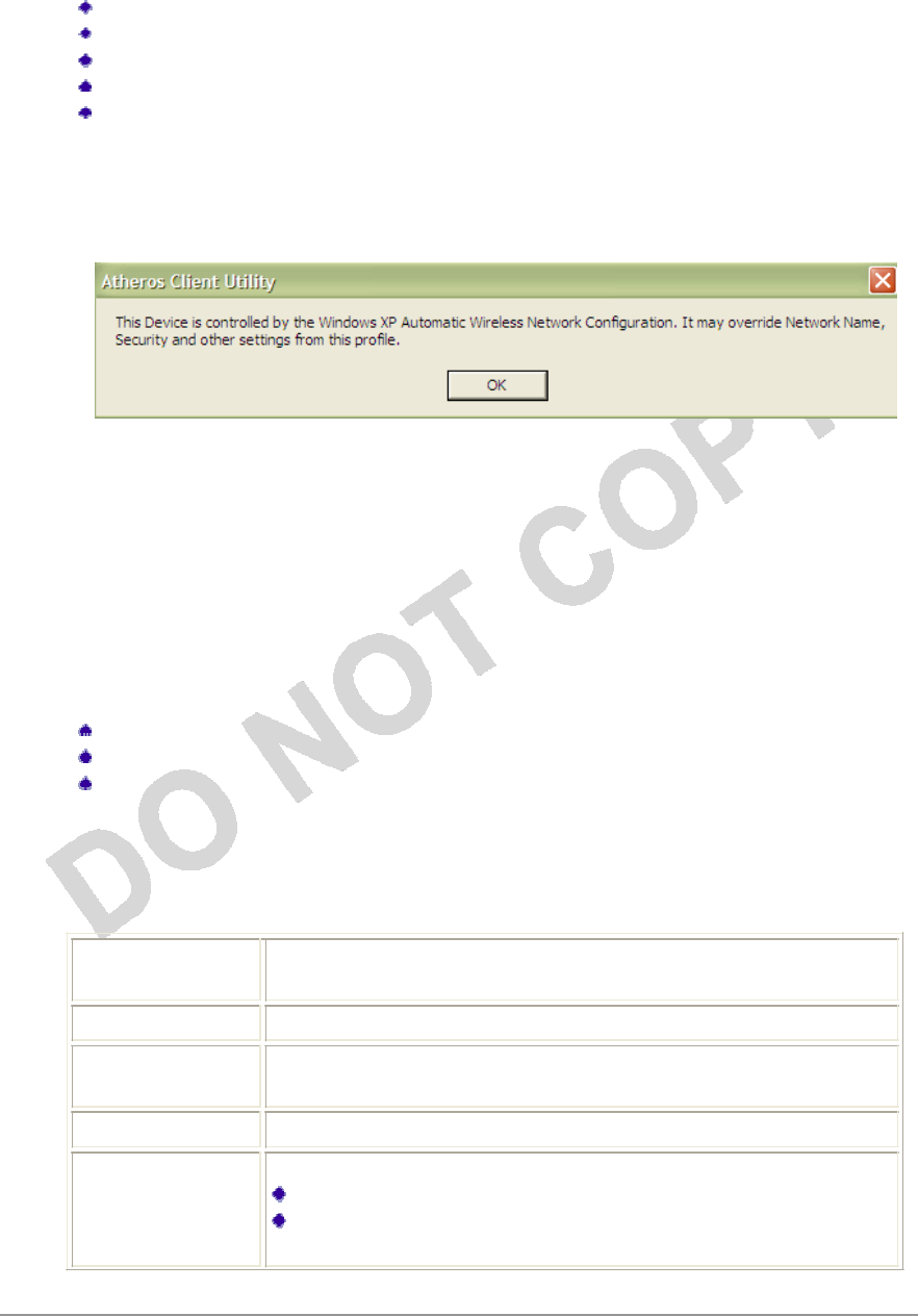
When Zero Configuration is in use, a pop-up message is displayed on the ACU when you
attempt to create or edit a configuration profile from the Profile Management tab of the
ACU.
To turn Zero Configuration off on Windows XP, take the following
steps:
1. In Windows XP, open the Wireless Network Configuration Properties dialog
box.
2. Clear the check box “Use Windows to configure my wireless network settings” to
set
Zero Configuration. When this check box is cleared, all profile settings are
controlled
by the configuration profile, which is set up from the ACU Profile Management
tab.
Check the Status Information or Diagnostics
The Azurewave client utility includes a number of tools to display current diagnostics
and
status
information.
Check current
status
Check driver
information
Check receive and transmit
diagnostics
Current
Status
The Current Status tab contains general information about the program and
its
operations. The Current Status tab does not require any configuration. The
following
table describes the items found on the Current Status
screen.
Profile Name The name of the current selected configuration profile. Set up
the
configuration name on the General
tab.
Link Status Shows whether the station is associated to the wireless
network.
Wireless Mode Displays the wireless mode. Configure the wireless mode on
the
Advanced
tab.
IP Address Displays the computer's IP
address.
Network Type The type of network the station is connected to. Options
include:
Infrastructure (access
point)
Ad
Hoc
Configure the network type on the Advanced
tab.
Azurewave Technologies. Inc., •
x
i
x
COMPANY CONFIDENTIAL January
2011
C
u
rre
n
t
C
h
a
nn
e
l
Shows the currently connected
channel.
Server
Base
d
A
u
t
h
e
n
t
i
cat
ion
Shows whether server based authentication is
used.
Data
En
cry
p
t
ion
Displays the encryption type the driver is using. Configure
the
encryption type on the Security
tab.
Sign
a
l
S
tre
ng
t
h
Shows the strength of the
signal.
Click the Advanced button to see the advanced status
diagnostics.
Adapter Information Button
The Adapter Information button contains general information about the
network
interface card (the wireless network adapter) and the network driver
interface
specification (NDIS) driver. Access the adapter information from the Diagnostics
tab.
Card
Name
Name of the wireless network
a
d
ap
t
er.
MAC
A
dd
ress
MAC address of the wireless network
a
d
ap
t
er.
Dr
i
ver
Driver name and path of the wireless network
a
d
ap
t
er
d
ri
v
er.
Driver
V
ers
ion
Version of the wireless network adapter
d
ri
v
er.
Driver
Date
Creation date of the wireless network adapter
d
ri
v
er.
Client
Name
Name of the client
com
pu
t
er.
Diagnostics Tab
The ACU Diagnostics tab provides allows retrieval of receive and transmit statistics.
The
Diagnostics tab does not require any configuration. It lists these receive and
transmit
diagnostics for frames received by or transmitted by the wireless network
adapter:
Multicast packets transmitted and
received
Broadcast packets transmitted and
received
Unicast packets transmitted and
received
Total bytes transmitted and
received
The Adapter Information button has general information about the wireless
network
adapter and NDIS driver. The Advanced Statistics button to shows statistics
for
diagnostics for frames received by or transmitted to the wireless network
adapter:
Azurewave Technologies. Inc.,
8F.,No.94,BaozhongRd.,Xiandian,Taipei,Taiwan231
Transmitted
F
rames
F
ra
m
e
s
t
ran
sm
i
tt
e
d
O
K
Frames
re
t
rie
d
F
ra
m
e
s
d
r
o
ppe
d
N
o
ACK
fra
m
e
s
ACK
fra
m
e
s
RTS
fra
m
e
s
C
lear-
to
-
s
en
d
(
CTS
)
fra
m
e
s
No CTS
fra
m
e
s
Retried
RTS
fra
m
e
s
R
e
t
rie
d
d
a
t
a
fra
m
e
s
Received
F
rames
Frames
re
c
ei
v
e
d
O
K
B
ea
co
n
s
Frames with
err
o
r
s
CRC
err
o
r
s
E
n
c
r
y
p
t
i
o
n
err
o
r
s
D
upli
c
a
t
e
frames
A
P
m
i
sm
a
tc
he
s
Data rate
m
i
sm
a
tc
he
s
Authentication
t
i
m
e-
o
u
t
Authentication rejects: the number of
A
P
authentication
failures received by the
wireless
network adapter
Association
t
i
m
e-
o
u
t
Association rejects: the number of AP authentication
re
j
e
cts
received by the wireless network
a
d
ap
t
er
Standard MIC
O
K
Standard
MIC
err
o
r
s
CKIP
MIC
O
K
CKIP MIC
err
o
r
s
Scan
A
v
a
il
a
b
l
e
N
e
tw
o
rk
s
Click the Scan button on the Profile Management tab to scan for available
infrastructure
and ad hoc networks. On this list, click Refresh to refresh the list at any
time.
Connecting to a different
n
et
wo
rk
Highlight a network name and click the Activate button to connect an
available
network. If no configuration profile exists for that network, the Profile
Management
window opens to the General tab. Fill in the profile name and click OK to create
the
configuration profile for that
network.
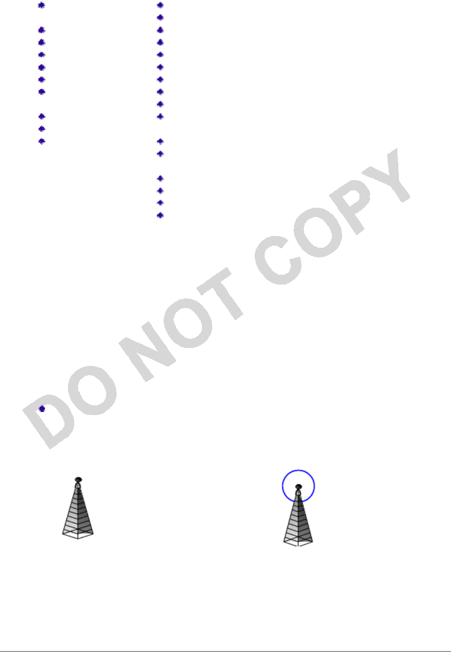
I
nfrastructure
(AP)
Network
Connected
I
nfrastructure
(AP)
Network
Azurewave Technologies. Inc., •
xx
i
COMPANY CONFIDENTIAL January
2011
Ad
Hoc
Network
Encryption
Active
Connected
Ad
Hoc
Network
Azurewave Technologies. Inc.,
8F.,No.94,BaozhongRd.,Xiandian,Taipei,Taiwan231

Display Settings
To change the display settings, choose Options > Display Settings from the menu.
The
display settings dialog box contains tools to set
the:
Signal Strength
D
i
s
pl
ay
U
ni
ts
Sets the units used when displaying
signal
strength: percentage (%) or
dBm.
Refresh Interval Use the up/down arrows to set the display
refresh
interval in
seconds.
Data Display Sets the display to cumulative or
relative:
Relative displays the change in statistical
data
since
the last
update.
Cumulative displays statistical data
collected
since opening the
profile.
ACU Tools
Use the Action menu to access the Azurewave Client Utility
tools:
Enable/Disable Radio Enable or disable the RF Signal on all
Azurewave
station reference
designs.
Enable/Disable
T
ray
I
c
on
Enable or disable the tray
icon.
Troubleshooting Run the optional Troubleshooting
Utility.
Manual LEAP Login Log in to LEAP manually, if LEAP is set
to
manually prompt for user name and password
on
each
login.
Reauthenticate Reauthenticate to a LEAP-configured
access
point.
Exit Exit the Azurewave Client Utility
application.
Azurewave Technologies. Inc., •
xx
iii
COMPANY CONFIDENTIAL January
2011

Tray Icon
The tray icon appears at the bottom of the screen, and shows the signal strength
using
colors and the received signal strength indication
(RSS
I
).
Hold the mouse cursor over the tray icon to display the current configuration
profile
name and association, as well as transmit and receive speed and the wireless
adapter
name and IP address. Right-click on the tray icon
to:
Help Open the online
help.
Open Azurewave
C
li
e
n
t
Ut
ili
ty
Launch the Azurewave Client Utility (ACU). Use the
ACU
to
configure a profile or view status and
st
a
t
i
st
i
cs
inf
o
r
m
a
t
i
o
n.
Troubleshooting Run the Troubleshooting
Ut
ili
ty
.
Preferences Set the ACU startup and menu options. Check to
st
ar
t
the
program automatically when Windows starts,
an
d
check
menu items that should appear on the
p
o
pup
m
enu.
Enable/Disable Radio Enable or disable the RF
s
i
g
nal.
Manual LEAP Login Log in to LEAP manually, if LEAP is set to
m
anuall
y
prompt
for user name and password on each
l
og
in.
Reauthenticate Reauthenticate to the access
p
o
in
t
.
Select Profile Click a configuration profile name to switch to. If
n
o
configuration profile exists for a connection, add
a
pr
o
file.
Show
C
onn
ect
ion
S
tat
u
s
This window displays connection
inf
o
r
m
a
t
i
o
n:
Active Profile Displays the active configuration profile
name.
Auto
P
r
o
f
il
e
Selection Shows whether auto profile selection is
enabled.
C
onn
ect
ion
S
tat
u
s
Displays whether the adapter
is
connected to a
wireless
network.
Link Quality Lists the quality of the link
connection.
SSID Displays the SSID of the associated
network.
Access
Poin
t
Azurewave
Technologies.
Inc.,
8F.,No.94,
Baozhong
Rd.,Xiandian,Taip
ei,Taiwan231
Name
Access
Poin
t
IP
A
dd
ress
Shows the name of the AP the
wireless
adapter is
connected
to.
Shows the IP address of the
access
point the
wireless adapter
is
connected
to.
Link Speed Lists the speed of the link
connection.
A
d
a
p
ter
IP
Address Displays the IP address of the wireless
adapter.
Exit Exit the Azurewave Client Utility
appli
c
a
t
i
o
n.
The colors are defined as
follows:
C
olo
r
Qu
a
li
ty
R
SSI
*
Green
Excellent
20 dB
+
Green
Good
10-20 dB
+
Yellow
Poor
5-10
dB
Red
Poor
< 5
dB
Gray
No
Connection
No
Connection
*Received signal strength indication RSSI. Displayed in dB or percentage. Enable
or
disable the tray icon in the Action
menu.
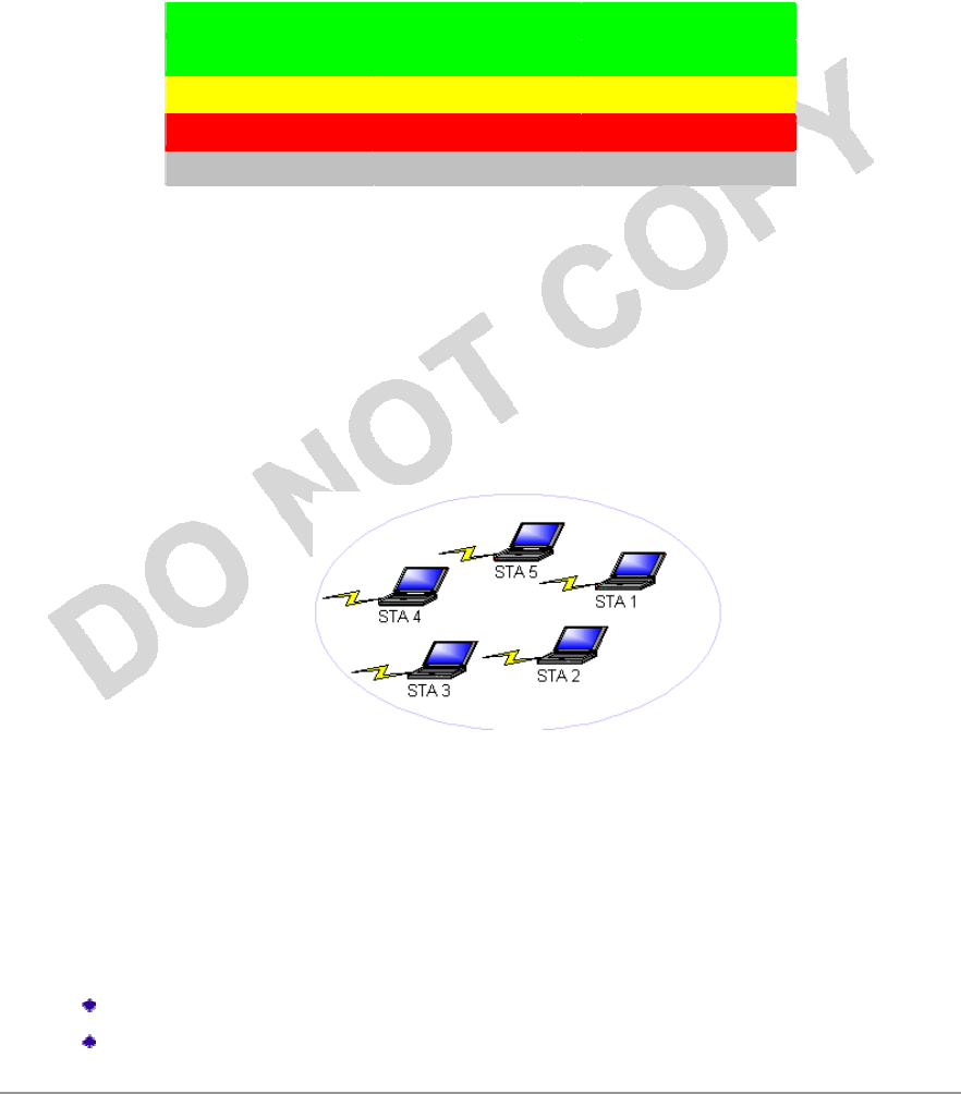
Ad Hoc Mode
In ad hoc mode, a wireless network adapter works within an independent basic
service
set (IBSS), as illustrated here. All stations communicate directly with other
stations
without using an access point
(AP).
To connect to an ad hoc network, configure the profile for ad hoc mode.
Ad
H
o
c
operation may be limited by Hardware to meet regulatory r
e
q
u
i
r
e
m
e
n
t
s
.
Ad Hoc Mode Profile
Configuration
To configure a profile in ad hoc mode, change the Network Type in the
Profile
Management's Advanced tab. For ad hoc mode, modify the
settings:
Network Name (on General
Tab)
Transmit Power
Level
Azurewave Technologies. Inc., •
xxv
COMPANY CONFIDENTIAL January
2011
802.11b Preamble (if using
802.11b)
Wireless Mode When Starting an Ad Hoc
Network
Make sure to also edit the General and Security
tabs.
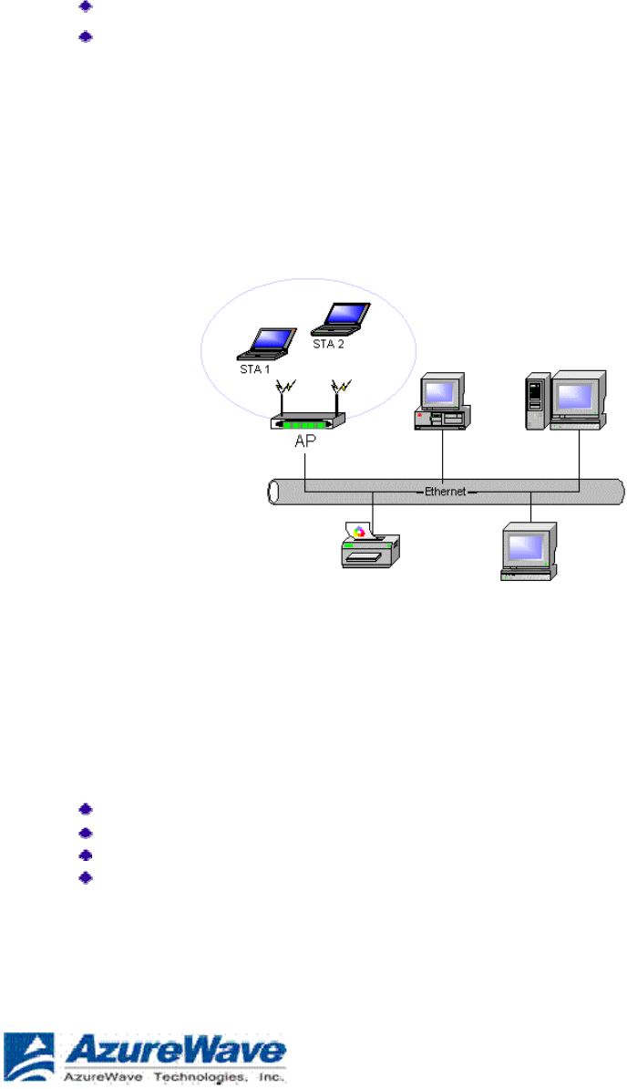
Infrastructure (Access Point) Mode
In infrastructure (access point (AP)) mode, the wireless network adapter participates in
a
basic service set (BSS) as a station, and communicates with the other stations through
an
AP, as illustrated
here.
To connect to an access point network, configure the profile for access point
mode
.
Infrastructure (Access Point) Mode Profile
Configuration
To configure a profile in infrastructure (access point) mode, change the Network Type
in
the Advanced tab. For access point mode, modify the
settings:
Power Save
Mode
802.11b Preamble (if using
802.11b)
Wireless
Mode
802.11 Authentication
Mode
Make sure to also edit the General and Security
tabs.
Azurewave Technologies. Inc.,
8F.,No.94,BaozhongRd.,Xiandian,Taipei,Taiwan231

Uninstall an Old Driver
Uninstall an old driver before upgrading to a new NDIS driver
release.
To remove the newly installed driver from the system if the system does not
have
previously installed versions of the NDIS driver, proceed to Step
4.
1. To remove the NDIS driver from the OS, go to Device Manager, right-click
Azurewave
AR500x Wireless Network Adapter, and choose
Uninstall.
2. Click OK to uninstall the
device.
3. When the device is uninstalled from Device Manager, search for and delete
the
driver files that reside in the
system.
a. Go to the Start menu and choose Search > For Files or
Folders.
b. Enter
oem*.inf
in the Search for files or folders named: field, and
enter
Azurewave in the Containing text:
field.
c. Click Search Now. A few files matching these criteria are possible, if
previous
drivers have not been removed
properly.
d. Choose the files that have been found and delete them from the
system.
4. To complete the uninstallation, remove the file ar5211.sys from the
folder
\W
I
NN
T
\
s
y
s
t
e
m
32\d
r
i
v
e
r
s
.
Additional Security Features
These security features prevent attacks on a wireless network's WEP keys. The
wireless
adapter automatically supports each of these features, but these features must be
enabled
on the access
point.
Message Integrity Check
(M
I
C)
MIC prevents bit-flip attacks on encrypted packets. In a bit-flip attack, someone intercepts
an encrypted message retransmits it after some alterations. Thus the receiver accepts
the
message as legitimate. The MIC adds some bytes to each packet to protect it against
tampering.
Temporal Key Integrity Protocol
(
T
K
IP
)
This feature prevents attacks on WEP in which someone catches encrypted packets
and
uses their initialization vector (IV) to decipher the WEP key. TKIP removes
the
predictability to protect both unicast and broadcast WEP
keys.
Broadcast Key
R
o
tat
ion
EAP authentication provides dynamic unicast WEP keys for wireless adapters, but
uses
static broadcast keys. In broadcast WEP key rotation, the access point supplies a dynamic
broadcast WEP key and changes it at
intervals.
Azurewave Technologies. Inc., •
xxv
ii
COMPANY CONFIDENTIAL January
2011

Bluetooth Adapter Installation and Operation
Getting
Started
This chapter describes how to install, uninstall, launch, and use the Bluetooth Suite.
The
following major topics are covered in this
chapter:
”Installing the Bluetooth
Suite”
”Launching the Bluetooth
Suite”
”Introduction to the Bluetooth
Suite”
“Uninstalling the Bluetooth
Suite”
Installing the Bluetooth Suite
You either received a password from Azurewave to download the Bluetooth Suite software from
the
Azurewave web site or received the Bluetooth Suite on a
CD.
NOTE: If you are installing Bluetooth Suite on a machine that already has an existing
Blue
t
oo
t
h
Suite, you need not uninstall it because Bluetooth Suite supports the upgrade feature. If you need
to uninstall Bluetooth Suite, refer to “Uninstalling the Bluetooth Suite” on page 2-10 on how
t
o
uninstall Bluetooth
Suite
.
Software installation is a three-step process and it is important to perform these steps before
you
can use the Bluetooth
Suite:
1. Installing the Bluetooth
Suite
2. Installing the radio (profile)
drivers
3. Updating the
drivers
All these steps are explained in the installation
process.
Downloading the Bluetooth
Suite
1. Go to the Azurewave Support web site:
h
tt
ps
://
suppor
t.
Azurewave
.
com
/
2. Login to the web site using your user name and password
provided
by Azurewave
Support.
3. Go to the AR3011 Software Package & Documentation tab of the Azurewave
web
site.
4. Download the appropriate Bluetooth Suite release, extract
the
files, and save them on your
system.
6. Install the Bluetooth Suite by double-clicking on the
Bluetooth
Suite setup.exe
file.
7.
Azurewave Technologies. Inc.,
8F.,No.94,BaozhongRd.,Xiandian,Taipei,Taiwan231
Follow the rest of the installation procedure described in “Copying Bluetooth Suite from
the
CD” on page
2-2.
Copying Bluetooth Suite from the
CD
1. Insert the CD containing the Bluetooth Suite into the CD
drive.
2. Double Click on the Bluetooth Suite setup.exe
file.
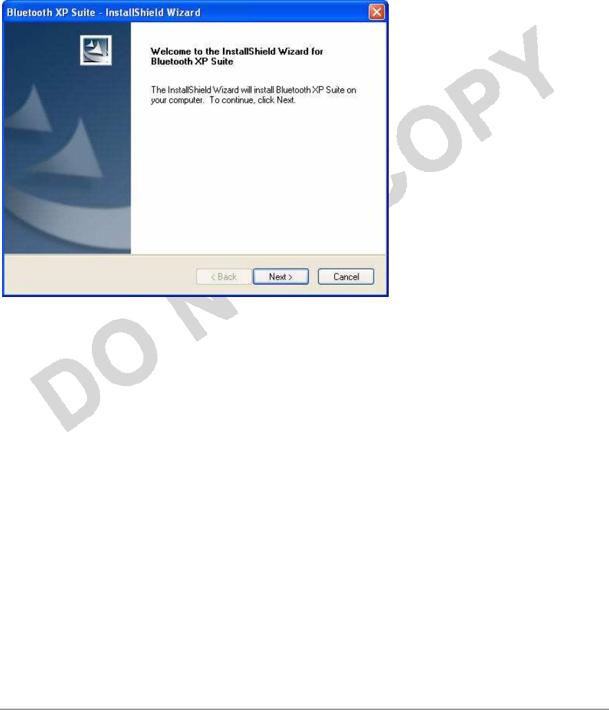
The InstallShield Wizard starts to prepare the package for installation. The Welcome
to
InstallShield Wizard for Bluetooth Suite screen (see Figure 2-1) is
displayed.
Figure 2-1. Bluetooth Suite - Welcome
Screen
3. Click
Next.
You will see the Customer Information screen. See Figure
2-2.
Azurewave Technologies. Inc., •
xx
i
x
COMPANY CONFIDENTIAL January
2011
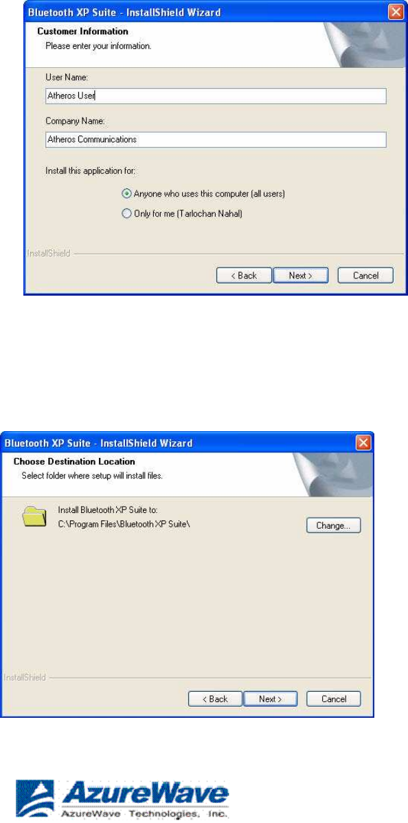
Figure 2-2. Bluetooth Suite Customer Information
Screen
4. Enter the user name and company name and choose the intended user of this
application
- “Anyone who uses this computer (all users)” or “Only for me” and click
Next
.
You will see Choose Destination Location screen. See Figure
2-3.
Figure 2-3. Bluetooth Suite Choose Destination
Location
Azurewave Technologies. Inc.,
8F.,No.94,BaozhongRd.,Xiandian,Taipei,Taiwan231
5. The default destination location is already selected.
Click
Change to browse to a different
destination.
6. Click
Next
.
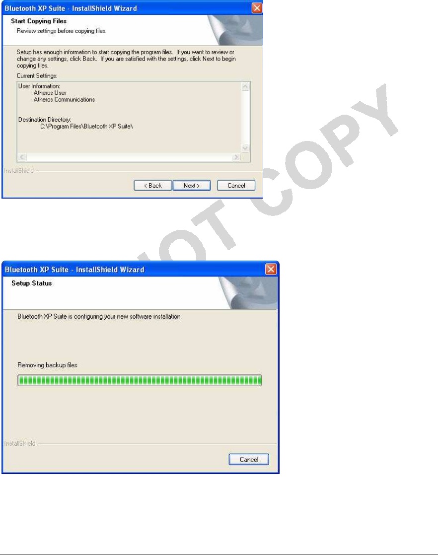
You will see Start Copying Files screen that displays the current settings including
user
information, setup type, and destination directory. This allows you to review
and
modify
the setup information. See Figure
2-4.
Figure 2-4. Bluetooth Suite - Start Copying
Screen
7. Click Next. The Bluetooth Suite begins to configure and copy the new software.
I
t
also removes any backup files. When the Bluetooth Suite installation is complete, you
will
see the Finish screen. See Figure
2-5.
Figure 2-5. Bluetooth Suite - Installation Setup
Status
8. When prompted to restart your computer, select Yes, I want to restart
my
computer now option and click
F
i
n
i
sh
.
Azurewave Technologies. Inc., •
xxx
i
COMPANY CONFIDENTIAL January
2011
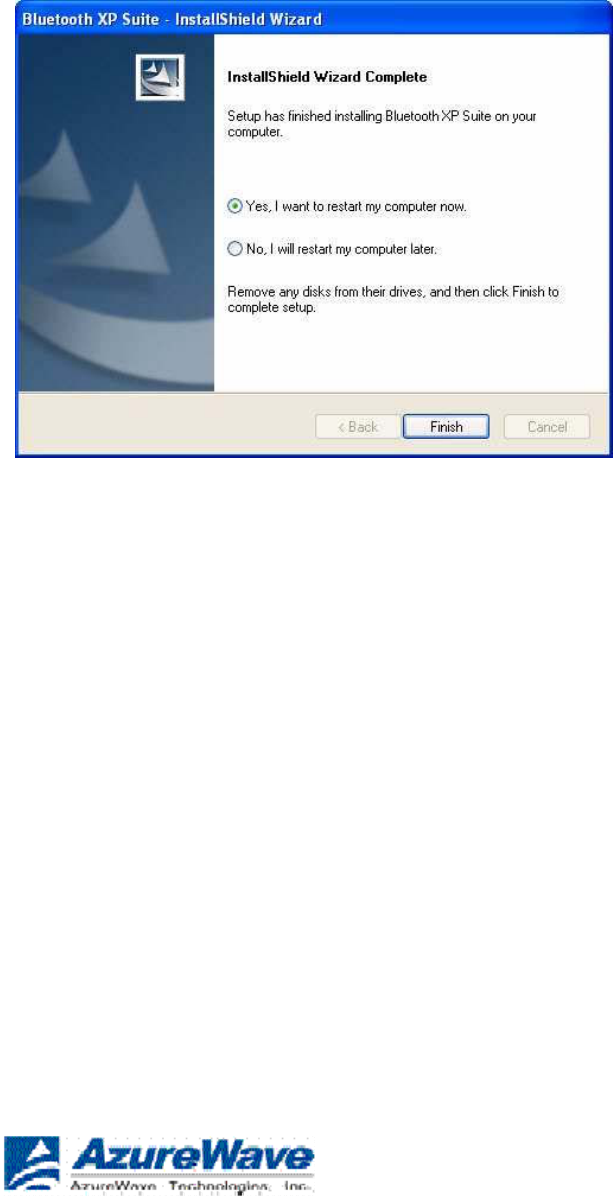
Figure 2-6. Bluetooth Suite - Finishing the
Installation
The installation is complete. This process creates a ‘Launch Bluetooth Suite’ shortcut on
your
desktop. Now you are ready to run Bluetooth
Suite.
Launching the Bluetooth Suite
1. Insert the Bluetooth Suite USB device into the USB port of
your
system.
NOTE: You can insert the Bluetooth Suite USB device in any USB port. You might see
Found
New Hardware
message
.
2. Double click on the Bluetooth Suite icon on your desktop or
choose
start > All Programs > Bluetooth Suite > Launch Bluetooth
Su
i
te
.
It displays the blank Azurewave Bluetooth Suite
screen.
NOTE: If no Bluetooth devices are found within range, it is normal for new ins
t
alla
t
ion
.
Bluetooth Suite screen does not display such devices when launched for the first
t
ime
.
You need to click on the Discovery button the top left panel of the window to see
all
t
he
Bluetooth devices in range. See Figure
2-7
.
Azurewave Technologies. Inc.,
8F.,No.94,BaozhongRd.,Xiandian,Taipei,Taiwan231
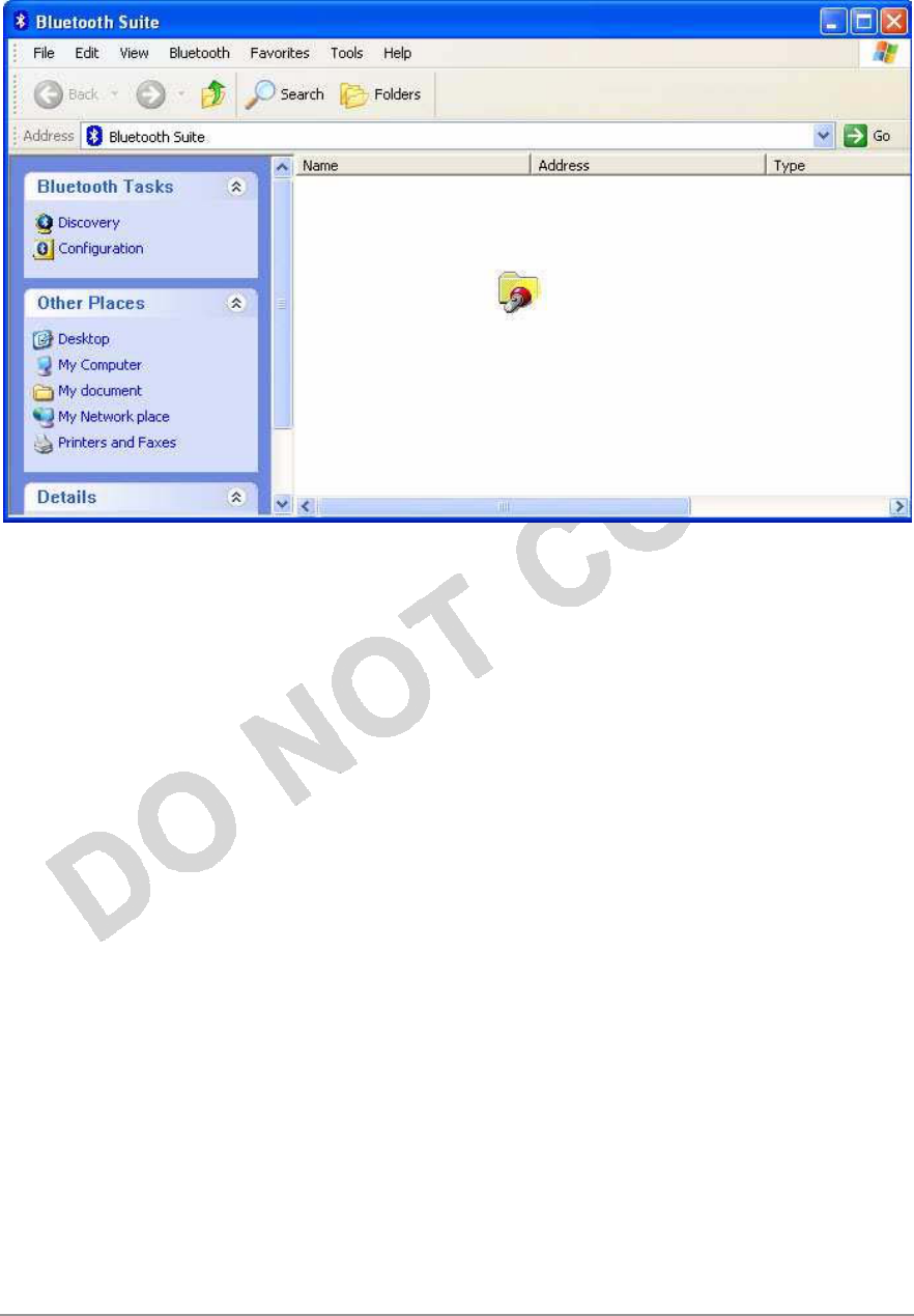
Figure 2-7.
Bluetooth Suite
Startup Screen
During
D
i
sc
o
v
e
r
y
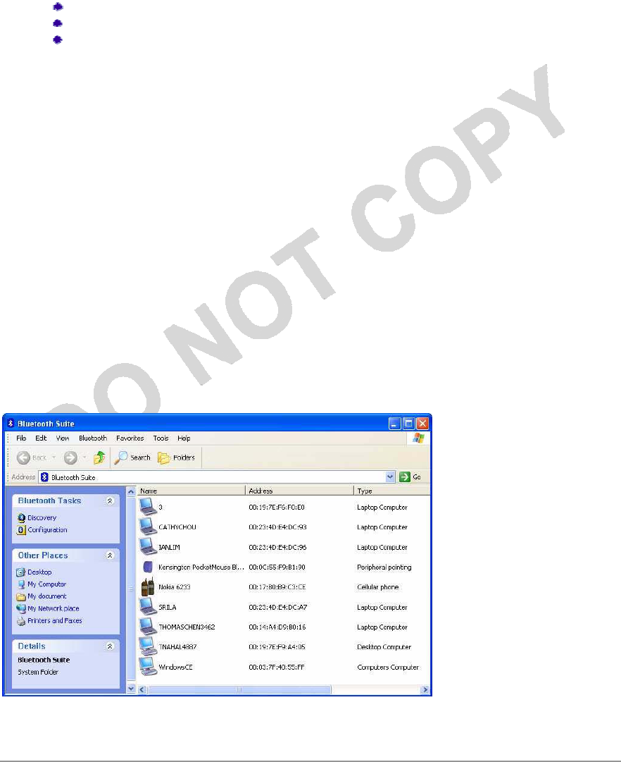
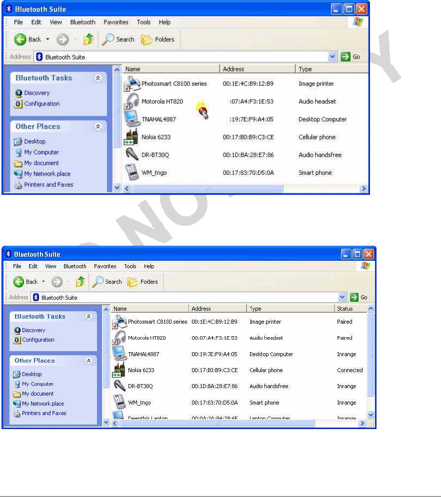
When the Bluetooth Suite finds devices in range, it displays them. See Figure
2-8.
Azurewave Technologies. Inc., •
xxx
iii
COMPANY CONFIDENTIAL January
2011
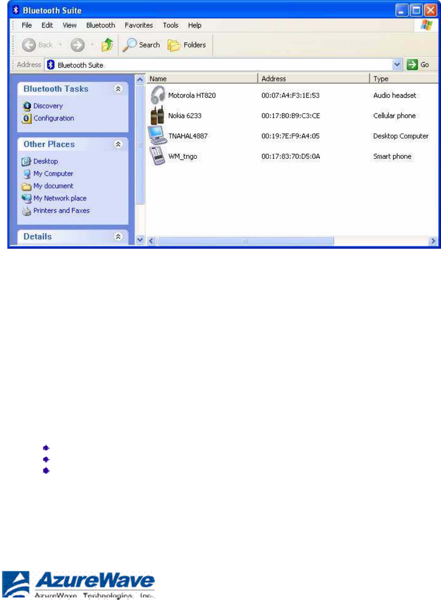
Figure 2-8. Discovered Bluetooth
Devices
NOTE: Trusted remote devices will show Paired status in Device list, and Connected
remo
t
e
devices will show Connected status in Device list. Other devices will display Inrange
s
t
a
t
us
.
Introduction to the Bluetooth Suite
Now that you have successfully launched the Bluetooth Suite, spend few minutes in getting
to
know your Bluetooth Suite. The following few pages explain various features and
components
associated with the Bluetooth Suite
GU
I
.
The My Bluetooth Suite is the main screen that consists of three major
parts:
Menu
bar
Bluetooth Tasks
area
Bluetooth devices along with their IP addresses and types
are
displayed on the right
panel.
In addition, there is a Bluetooth Suite Tray which allows you to
launch
the Bluetooth
Suite.
Azurewave Technologies. Inc.,
8F.,No.94,BaozhongRd.,Xiandian,Taipei,Taiwan231

Menu
Bar
Bluetooth menu is the primary menu on the Bluetooth Suite screen. The options associated
with
this menu
are:
Search for
Device
Bluetooth
Configuration
Bluetooth Help
Topics
Bluetooth Exchange
Folder
About
Bluetooth
NOTE: Some of these functions are available from the Bluetooth Suite
Tray
.
These options are described below in
detail.
Search For
Device
Clicking this button begins to search for remote Bluetooth devices in range. Found devices
will
display in right
panel.
Bluetooth
Configuration
Clicking on the Configuration menu option displays the Bluetooth Suite Configuration
screen
which allows you to specify Bluetooth Suite tasks and settings associated with Bluetooth
device
recovery and device filters. This function is also available through the toolbar. Nine configuration
screens are associated with Bluetooth Suite. Those screens
are:
Bluetooth Suite
Settings
Local
Device
Bluetooth
Security
Profile
Manager
Shared
Folders
Object
Push
Audio
Basic
Imaging
Personal Area
Networking
Fax Server
Configuration
Sync
These options are described in detail in Chapter
3.
Bluetooth Help
Topics
Click this button to display any help
topics.
Azurewave Technologies. Inc., •
xxxv
COMPANY CONFIDENTIAL January
2011
Bluetooth Exchange
Folder
Clicking this button to display the content of Bluetooth exchange folder. From
Bluetooth
Suite window, choose Bluetooth->Bluetooth Exchange Folder to access
Exchange
share folder for Object Push
feature.
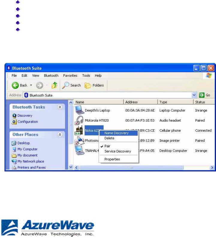
Bluetooth Places
Panel
When you launch the Bluetooth Suite, various Bluetooth devices in the
Bluetooth
neighborhood are listed on the right panel. These typically consist
of
audio devices, computers (both laptop and desktop), phones,
peripheral
devices such as Fax, printer, mouse, headset, and imaging devices.
If
any of these devices are discovered, they are listed on the
right
window
panel. For example, if a Bluetooth mouse is discovered in
the
Bluetooth neighborhood, it is shown as peripheral pointing device,
its
brand name, address, and service status (in range, paired, connected
or
disconnected). You can select a device and right mouse click button
to
select the
following:
Name
discovery
Delete
Pair
Service
Discovery
Properties
See Figure 2-9 for
details.
Figure 2-9. Bluetooth Places Device
Options
Azurewave Technologies. Inc.,
8F.,No.94,BaozhongRd.,Xiandian,Taipei,Taiwan231
Uninstalling the Bluetooth Suite
Anytime you install a new version of Bluetooth Suite, you need
to
uninstall any existing version of the Bluetooth Suite. Follow
this
procedure to uninstall the Bluetooth
Suite.
1. Make sure the Bluetooth dongle is removed from any system
USB
port.
2. Choose start > All Programs > Bluetooth Suite > Uninstall Bluetooth
Su
i
te
.
The system prepares for uninstallation. A screen is briefly displayed that shows that it is
ready
to
uninstall the program. You will see another screen that prompts you to completely
remove
the
application and all of its features. See Figure
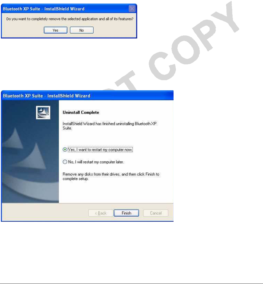
2-10.
Figure 2-10. Bluetooth Suite Uninstallation
Prompt
3. Click
Yes
.
You will see a Setup Status screen showing that application is being removed followed
by
another screen showing Uninstall Complete. See Figure
2-11
.
Figure 2-11. Finishing Bluetooth Suite
Uninstallation
4. Click Yes, I want to restart my computer
now.
5. Click
F
i
n
i
sh
.
Azurewave Technologies. Inc.,
•xxxv
ii
COMPANY CONFIDENTIAL January
2011

The uninstall is complete. You are ready to reinstall the Bluetooth
Suite.
Azurewave Technologies. Inc.,
8F.,No.94,BaozhongRd.,Xiandian,Taipei,Taiwan231
Connecting to an HID Device
This chapter describes how to connect the Bluetooth laptop to a Bluetooth HID
(Human
Interface Device) such as a
mouse.
Setup Requirements
You need the following devices and equipment in order to accomplish this
task:
A PC system running Windows with Bluetooth
Suite
Azurewave Bluetooth USB Adapter
(dongle)
Bluetooth mouse with batteries or
keyboard
Launching the Bluetooth Suite
1. Double click on the Launch Bluetooth Suite icon on your desktop
or
launch it from start > All Programs > Bluetooth Suite > Launch Bluetooth
Su
i
te
.
It displays theBluetooth Suite start-up screen. See Figure
4-1.
2. Put your mouse in searchable (pairing mode) by doing
the
following:
a. Turn On the mouse by pressing down its power On/Off
button.
Refer to the mouse documentation on how to do
it.
b. Press the connect button on the mouse to put it in
pairing
(discoverable) mode. Refer to the mouse documentation
for
additional
information.
3. Right mouse click on the Bluetooth Suite Tray, and choose My
B
l
uetooth
Place
option.
It displays all the peripheral devices in the right panel of the screen indicating that these
devices
are in range and available to be connected. It also shows the device name, address, type and status
(in range, paired, or
connected).
Azurewave Technologies. Inc., •
xxx
i
x
COMPANY CONFIDENTIAL January
2011
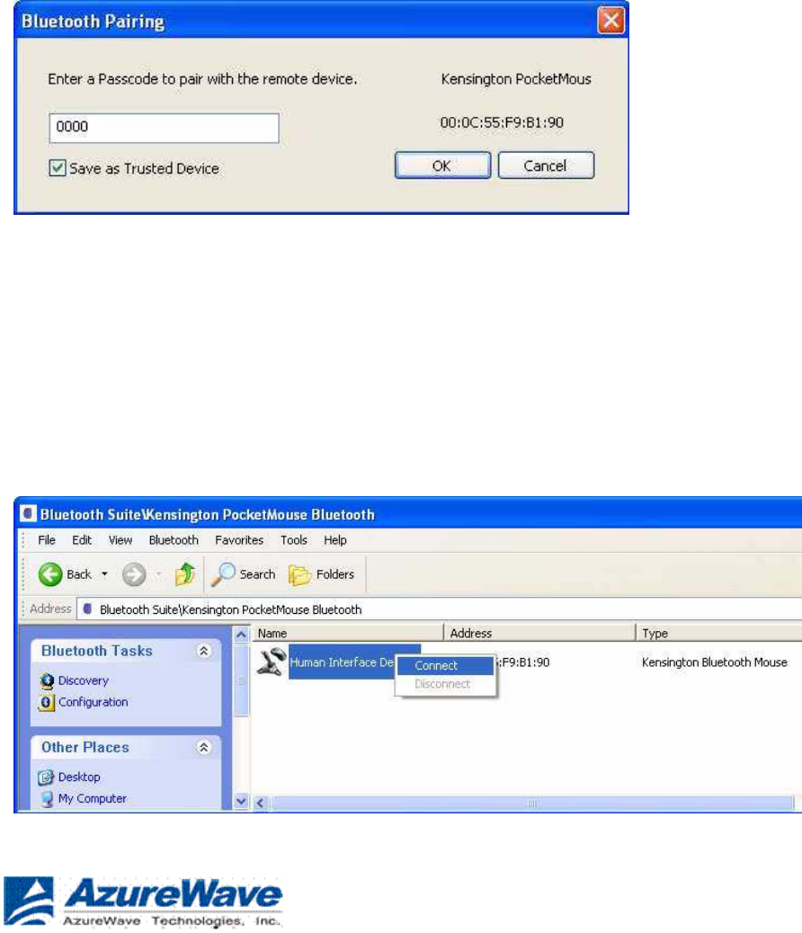
Figure 4-1. Bluetooth Places
Screen
4. Make sure the device that you wish to pair or connect
is
powered
up and in discoverable mode. If it is in range and
has
previously been paired, turning on the device
will
automatically
pair
it.
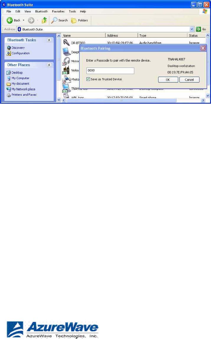
5. Right click on the mouse and choose Pair. It displays
the
Bluetooth Pairing Passcode screen. See Figure
4-2.
Figure 4-2. Entering Bluetooth Pairing
Passcode
6. Enter a passcode to pair with the remote device and click
OK
.
NOTE: The default code shown is 0000. Refer to the documentation of your
mouse
t
o
find out the passcode of your device and how to change
it
.
7. Highlight the mouse device under Peripheral Devices in
the
left panel and choose Service Discovery. Highlight the
device.
Using your laptop pointing device, right click on the
Human
Interface Device service and choose the Connect option
to
connect to the
mouse.
Figure 4-3. Connecting the
Mouse
Azurewave Technologies. Inc.,
8F.,No.94,BaozhongRd.,Xiandian,Taipei,Taiwan231

8. Right click the Connect
button.
Azurewave Technologies. Inc., •
xli
COMPANY CONFIDENTIAL January
2011
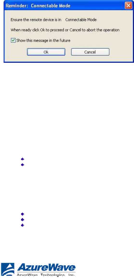
9. You will be prompted to make sure the device is
in
discoverable mode. Make sure the device in ON and
in
connectable mode. See Figure
4-4.
Figure 4-4. Putting Device in Connectable
Mode
10. Click
OK
.
You will notice that the Wizard begins to install software for the HID device. As soon as
the
installation is complete, the screen
disappears.
Its service status of the HID changes from Disconnected to Connected. Your mouse is
now
connected and ready to use. You can perform normal mouse functions using this
mouse.
Connecting to a Sync Device
This chapter describes how to connect a Bluetooth laptop to a
Bluetooth
device that supports Synchronization profile. The following topics
are
covered in this
chapter:
“Setup
Requirements”
“Launching the Synchronization
Process”
Setup Requirements
You need the following devices and equipment in order to accomplish this
task:
A laptop system running Windows XP with Bluetooth
Suite
Bluetooth USB
Adapter
A Bluetooth device such as an e-mail tool and calendar
that
supports sync
profile
Azurewave Technologies. Inc.,
8F.,No.94,BaozhongRd.,Xiandian,Taipei,Taiwan231
Launching the Synchronization Process
1. Launch the Bluetooth
Suite.
2. Choose My Bluetooth Place from the Bluetooth tray on your desktop. It
displays
the My Bluetooth Place start-up
screen.
3. Right mouse click the blank panel and choose Device Discovery option. See
Figure
10-1.
Figure 10-1. Bluetooth Suite Discovery
Screen
4. Highlight the device that you wish to sync with and pair it. See Figure
10-2.
Figure 10-2. Pairing the Device for
Syncing
5. Right mouse click on the desired bluetooth device and
select
the Pair
option.
Azurewave Technologies. Inc., •
x
liii
COMPANY CONFIDENTIAL January
2011
6. Enter the pairing code (0000) to pair it and click OK.
See
Figure
10-3.
Figure 10-3. Bluetooth Devices
Pairing
7. You will see the passcode prompt. Enter the passcode
(default
is 0000) for the selected device and click
OK
.
NOTE: The default code shown is 0000. Refer to the documentation of your device to find
ou
t
the passcode of your device and how to change
i
t.
8. Right click the SYNC icon on My Bluetooth Place under
the
specified device screen and choose Synchronization option.
See
Figure
10-4.
Azurewave Technologies. Inc.,
8F.,No.94,BaozhongRd.,Xiandian,Taipei,Taiwan231
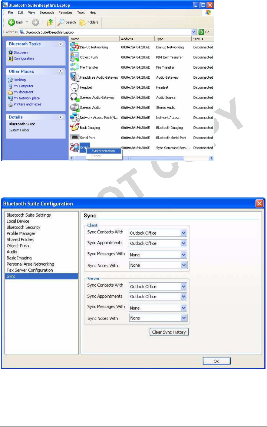
Figure 10-4. Bluetooth
Synchronization
It displays the Sync screen which allows you to specify sync parameters for both
client
and server. See Figure
10-5.
Azurewave Technologies. Inc., •
x
l
v
COMPANY CONFIDENTIAL January
2011

Figure 10-5. Selecting Items to
Synchronize
9. Select the Sync items under the server and client that
you
wish to synchronize and click
OK
.
The selected items will be
synchronized.
Azurewave Technologies. Inc.,
8F.,No.94,BaozhongRd.,Xiandian,Taipei,Taiwan231

Advanced Status Information
Click the Advanced button on the Current Status tab of the Azurewave Client Utility to
see
advanced information about the program and its operations. The Current Status tab
does
not require any configuration. The following table describes the items found on
the
Advanced Status
screen.
Network Name (SSID) Displays the wireless network
na
m
e.
Configure the network name on the General
t
a
b
.
Server
Base
d
A
u
t
h
e
n
t
i
cat
ion
Shows whether server based authentication is
u
s
e
d
.
Data Encryption Displays the encryption type the driver is using.
Co
nfi
g
ure
the
encryption type on the Security
t
a
b
.
Authentication Type Displays the authentication
mod
e.
Configure the authentication mode on the General
t
a
b
.
Message
In
te
g
r
i
ty
C
h
eck
Shows whether MIC is enabled. MIC prevents bit-flip
a
tt
a
cks
on
encrypted
pa
ck
e
ts
.
Associated AP Name Displays the name of the access point the
wireless
adapter is
associated
to
.
Associated
A
P
IP
A
dd
ress
Associated
A
P
MAC
A
dd
ress
Shows the IP address of the access point the
w
irele
ss
a
d
ap
t
er
is
associated
to
.
Displays the MAC address of the access point
t
he
wireless
adapter is associated
to
.
Power Save Mode Shows the power save mode. Power management
i
s
d
i
s
a
b
le
d
in
ad hoc
mod
e.
Configure the power save mode on the Advanced
t
a
b
.
Current Power Level Displays the transmit power level rate in
mW.
Current Signal Strength Shows the current signal strength
in
dBm
.
Current Noise Level Displays the current noise level
in
dBm
.
Up Time Shows how long the client adapter has been receiving
p
ow
er
(in
hours:minutes:seconds). If the adapter runs for more
t
han
24
hours, the display shows in
d
a
ys
:h
o
ur
s
:
m
inu
t
e
s
:
s
e
co
n
ds
.
802.11b Preamble Displays the 802.11b
prea
mb
le
f
o
r
m
a
t
.
Configure the preamble format on the Advanced
t
a
b
.
Current Receive Rate Shows the current receive rate
in
Mb
p
s
.
Current Transmit Rate Displays the current transmit rate
in
Mb
p
s
.
Channel Shows the currently connected
c
hannel.
Frequency Displays frequency the station is
u
s
in
g
.
Channel Set Shows the current
c
hannel
s
e
t
.
Azurewave Technologies. Inc., •
x
l
v
ii
COMPANY CONFIDENTIAL January
2011

Federal
Communication
Commission
Interference
S
t
a
t
e
m
en
t
This equipment has been tested and found to comply with the limits for a Class B digital
device,
pursuant to Part 15 of the FCC Rules. These limits are designed to provide reasonable
protection
against harmful interference in a residential installation. This equipment generates, uses and
can
radiate radio frequency energy and, if not installed and used in accordance with the
instructions,
may cause harmful interference to radio communications. However, there is no guarantee
that
interference will not occur in a particular installation. If this equipment does cause
harmful
interference to radio or television reception, which can be determined by turning the equipment off
and on, the user is encouraged to try to correct the interference by one of the following measures:
- Reorient or relocate the receiving
antenna.
- Increase the separation between the equipment and
receiver.
- Connect the equipment into an outlet on a circuit different from
that
to which the receiver is
connected.
- Consult the dealer or an experienced radio/TV technician for
help.
This device complies with Part 15 of the FCC Rules. Operation is subject to the following
two
conditions: (1) This device may not cause harmful interference, and (2) this device must
accept
any interference received, including interference that may cause undesired
operation.
FCC Caution: Any changes or modifications not expressly approved by the party responsible
for
compliance could void the user's authority to operate this
equipment.
IMPORTANT
N
O
T
E:
FCC Radiation Exposure
S
t
a
t
e
m
en
t
:
The product comply with the US/Canada portable RF exposure limit set forth for an uncontrolled
environment and are safe for intended operation as described in this manual. The further
RF
exposure reduction can be achieved if the product can be kept as far as possible from the
user
body or reduce output power if it doesn't affect the transmission/receiving
quality.
This transmitter must not be co-located or operating in conjunction with any other antenna
or
transmitter.
IEEE 802.11b or 802.11g operation of this product in the U.S.A. is firmware-limited to channels
1
through
11.
Azurewave Technologies. Inc.,
8F.,No.94,BaozhongRd.,Xiandian,Taipei,Taiwan231

This equipment has been SAR-evaluated for use in laptops (notebooks) with side
slot
configuration.
This device is intended only for OEM integrators under the following
conditions:
The transmitter module may not be co-located with any other transmitter or
antenna,
For all products market in US, OEM has to limit the operation channels in CH1 to CH11 for
2.4G
band by supplied firmware programming tool. OEM shall not supply any tool or info to the
end-
user regarding to Regulatory Domain
change.
As long as 2 conditions above are met, further transmitter test will not be required. However,
the
OEM integrator is still responsible for testing their end-product for any additional
compliance
requirements required with this module installed (for example, digital device emissions,
PC
peripheral requirements,
etc.).
IMPORTANT NOTE: In the event that these conditions can not be met (for example
certain
laptop
configurations or co-location with another transmitter), then the FCC authorization is
no
longer considered valid and the FCC ID can not be used on the final product. In
these
circumstances, the OEM integrator will be responsible for re-evaluating the end
product
(including the transmitter) and obtaining a separate FCC
authorization.
End Product
La
b
e
li
n
g
The final end product must be labeled in a visible area with the following:
“Contains TX FCC
I
D:
TLZ-NB086”.
Manual
Information
To the End
U
se
r
The OEM integrator has to be aware not to provide information to the end user regarding
how
to install or remove this RF module in the user’s manual of the end product which integrates
this
module.
The end user manual shall include all required regulatory information/warning as show in
this
manual.
RF exposure warning ·
This equipment must be installed and operated in accordance with provided instructions and the
antenna(s) used for this transmitter must be installed to provide a separation distance of at least
20 cm from all persons and must not be co-located or operating in conjunction with any other
antenna or transmitter. End-users and installers must be provide with antenna installation
instructions and transmitter operating conditions for satisfying RF exposure compliance.
Azurewave Technologies. Inc., •
xlix
COMPANY CONFIDENTIAL January
2011

Industry Canada
statement:
This device complies with RSS-210 of the Industry Canada Rules. Operation is subject to
t
he
following two conditions: (1) This device may not cause harmful interference, and (2) this
device
must accept any interference received, including interference that may cause
undesired
opera
t
ion
.
Ce dispositif est conforme à la norme CNR-210 d'Industrie Canada applicable aux appareils radio
exempts de licence. Son fonctionnement est sujet aux deux conditions suivantes: (1) le disposi
t
if
ne doit pas produire de brouillage préjudiciable, et (2) ce dispositif doit accepter tout
brouillage
reçu, y compris un brouillage susceptible de provoquer un fonctionnement
indésirable
.
IMPORTANT
NOTE:
Radiation Exposure
Statement:
The product comply with the US/Canada portable RF exposure limit set forth for
an
uncontrolled environment and are safe for intended operation as described in this manual.
The
further RF exposure reduction can be achieved if the product can be kept as far as possible
f
rom
the user body or set the device to lower output power if such function is
available
.
NOTE IMPORTANTE: (Pour l'utilisation des appareils
por
t
ables)
Déclaration d'exposition aux
radia
t
ions
:
Le produit est conforme aux limites d'exposition pour les appareils portables RF pour les
E
t
a
t
s-
Unis et le Canada établies pour un environnement non
con
t
rôlé
.
Le produit est sûr pour un fonctionnement tel que décrit dans ce manuel. La réduction
aux
expositions RF peut être augmentée si l'appareil peut être conservé aussi loin que possible
du
corps de l'utilisateur ou que le dispositif est réglé sur la puissance de sortie la plus faible si
une
telle fonction est
disponible
.
This device has been designed to operate with an antenna having a maximum gain of 3.59
dBi
.
Antenna having a higher gain is strictly prohibited per regulations of Industry Canada.
The
required antenna impedance is 50
ohms
.
(Le manuel d'utilisation de dispositifs émetteurs équipés d'antennes amovibles doit contenir
les
informations suivantes dans un endroit bien en
vue
:
)
Azurewave Technologies. Inc.,
8F.,No.94,BaozhongRd.,Xiandian,Taipei,Taiwan231

Ce dispositif a été conçu pour fonctionner avec une antenne ayant un gain maximal de dBi
3.59
Une antenne à gain plus élevé est strictement interdite par les règlements d'Industrie
Canada
.
L'impédance d'antenne requise est de 50
ohms
.
This device is intended only for OEM integrators under the following
cond
i
t
i
ons:
1) The transmitter module may not be co-located with any other transmitter or
antenna
,
2) For all products market in Canada, OEM has to limit the operation channels in CH1 to
CH11
for 2.4G band by supplied firmware programming tool. OEM shall not supply any tool or info
t
o
the end-user regarding to Regulatory Domain
change
.
As long as 2 conditions above are met, further transmitter test will not be required.
However
,
the OEM integrator is still responsible for testing their end-product for any
additional
compliance requirements required with this module
ins
t
alled
.
Cet appareil est conçu uniquement pour les intégrateurs OEM dans les conditions
suivan
t
es
:
(Pour utilisation de dispositif
module)
1) Le module émetteur peut ne pas être coïmplanté avec un autre émetteur ou
antenne,
2) Pour tous les produits vendus au Canada, OEM doit limiter les fréquences de
f
onc
t
ionnemen
t
CH1 à CH11 pour bandes de fréquences 2.4G grâce aux outils de microprogrammation
f
ournis
.
OEM ne doit pas fournir d'outil ou d'informations à l'utilisateur final en ce qui concerne
le
changement de réglementation de
domaine
.
Tant que les 2 conditions ci-dessus sont remplies, des essais supplémentaires sur l'émetteur
ne
seront pas nécessaires. Toutefois, l'intégrateur OEM est toujours responsable des essais sur son
produit final pour toutes exigences de conformité supplémentaires requis pour ce module ins
t
allé
.
IMPORTANT
NOTE:
In the event that these conditions can not be met (for example certain laptop configurations or
co-location with another transmitter), then the Canada authorization is no longer considered
valid and the IC ID can not be used on the final product. In these circumstances, the
OEM
integrator will be responsible for re-evaluating the end product (including the transmitter)
and
obtaining a separate Canada
au
t
horiza
t
ion
.
NOTE
I
MPORTANTE:
Dans le cas où ces conditions ne peuvent être satisfaites (par exemple pour
cer
t
aines
configurations d'ordinateur portable ou de certaines co-localisation avec un autre
éme
tt
eur)
,
l'autorisation du Canada n'est plus considéré comme valide et l'ID IC ne peut pas être
u
t
ilisé
sur le produit final. Dans ces circonstances, l'intégrateur OEM sera chargé de réévaluer
le
produit final (y compris l'émetteur) et l'obtention d'une autorisation distincte au
Canada
.
Azurewave Technologies. Inc., •
li
COMPANY CONFIDENTIAL January
2011

Manual Information To the End
User
The OEM integrator has to be aware not to provide information to the end user regarding
how
t
o
install or remove this RF module in the user’s manual of the end product which
in
t
egra
t
es
t
his
module
.
The end user manual shall include all required regulatory information/warning as show in
t
his
manual.
Manuel d'information à l'utilisateur
f
i
na
l
L'intégrateur OEM doit être conscient de ne pas fournir des informations à
l'
ut
ili
sateur
final quant à la façon d'installer ou de supprimer ce module RF dans le manuel
de
l'utilisateur du produit final qui intègre ce
modu
l
e
.
Le manuel de l'utilisateur final doit inclure toutes les informations
rég
l
ementa
i
res
requises et avertissements comme indiqué dans ce
manue
l.
Radio Frequency (RF) Exposure Information
The radiated output power of the Wireless Device is below the Industry Canada (IC) radio
frequency exposure limits. The Wireless Device should be used in such a manner such that the
potential for human contact during normal operation is minimized.
This device has also been evaluated and shown compliant with the IC RF Exposure limits under
mobile exposure conditions. (antennas are greater than 20cm from a person's body).
This device has been certified for use in Canada. Status of the listing in the Industry
Canada’s REL (Radio Equipment List) can be found at the following web address:
http://www.ic.gc.ca/app/sitt/reltel/srch/nwRdSrch.do?lang=eng
Additional Canadian information on RF exposure also can be found at the following web address:
http://www.ic.gc.ca/eic/site/smt-gst.nsf/eng/sf08792.html
Informations concernant l'exposition aux fréquences radio (RF)
La puissance de sortie émise par l’appareil de sans fil Dell est inférieure à la limite d'exposition aux
fréquences radio d'Industry Canada (IC). Utilisez l’appareil de sans fil Dell de façon à minimiser les
contacts humains lors du fonctionnement normal.
Ce périphérique a également été évalué et démontré conforme aux limites d'exposition aux RF d'IC
dans des conditions d'exposition à des appareils mobiles (les antennes se situent à moins de 20
cm du corps d'une personne).
Ce périphérique est homologué pour l'utilisation au Canada. Pour consulter l'entrée correspondant
à l’appareil dans la liste d'équipement radio (REL - Radio Equipment List) d'Industry Canada
rendez-vous sur:
http://www.ic.gc.ca/app/sitt/reltel/srch/nwRdSrch.do?lang=eng
Pour des informations supplémentaires concernant l'exposition aux RF au Canada rendez-vous sur :
http://www.ic.gc.ca/eic/site/smt-gst.nsf/eng/sf08792.html
Azurewave Technologies. Inc.,
8F.,No.94,BaozhongRd.,Xiandian,Taipei,Taiwan231
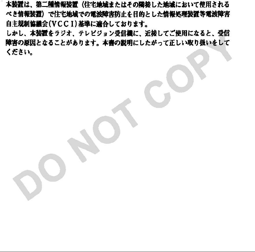
For NCC
S
t
a
t
e
m
en
t
依據國家通訊傳播委員會低功率電波輻射性電機管理辦法:
第十二條
經型式認證合格之低功率射頻電機,非經許可,公司、商號或使用者均不得擅自變更頻
率、加大功率或變更原設計之特性及功能。
第十四條
低功率射頻電機之使用不得影響飛航安全及干擾合法通信;經發現有干擾現象時,應立
即停用,並改善至無干擾時方得繼續使用。前項合法通信,指依電信法規定作業之無線電通信。 低
功率射頻電機須忍受合法通信或工業、科學及醫療用電波輻射性電機設備之干擾。
本模組於取得認證後將依規定於模組本體標示審合格籤,並要求平台上標示「本
產
品
內
含射頻模
組:
XXXXXXXXXX」
Japan Telecom
Certification
–
J
A
T
E
Azurewave Technologies. Inc., •
liii
COMPANY CONFIDENTIAL January
2011