AzureWave Technologies NM230NF IEEE 802.11 b/g/n Wireless LAN and Bluetooth combo M.2 1216 module User Manual AW AH691A
AzureWave Technologies, Inc. IEEE 802.11 b/g/n Wireless LAN and Bluetooth combo M.2 1216 module AW AH691A
Contents
- 1. Users Manual-1
- 2. Users Manual-2
- 3. User manual
- 4. User manual statement
Users Manual-1
- 1 -
AW-NM230NF-H
IEEE 802.11 b/g/n Wireless LAN and Bluetooth
Combo M.2 1216 Module
User Guide
Document
release
Date
Modification
Initials
Approved
Version 0.1
2015/03/10
Initial Version
Chao Lee
Amos Fu
Version 0.2
2015/8/3
Add pin definition , pin map
Chao Lee
Amos Fu
1. WLAN Basic Test
Driver Installation
Throughput Test
RF Tx/Rx Performance Test
2. Bluetooth Basic Test
Download Mini-driver
Throughput Test
RF Performance Test
3. Statement
4. Pin definition/Pin map

- 2 -
1. WLAN Basic Test
**Must connect USB to PC
Driver Installation
DRIVER INSTALLATION (IN LINUX)
•First prepare the Broadcom’s linux package, and put it in the “home”folder.
•Open the Terminal, enter the command: sudo su and password.
•Enter cd /home/username/drivername/src/dhd/linux
•Enter make dhd-cdc-sdmmc-gpl to generate the dhd.ko file in /home/username/ drivername
/src/dhd/linux/dhd-cdc-sdmmc-gpl-kernelversion
•Enter
Insmod /(path of dhd.ko file)
firmware_path=/(path of firmware file) nvram_path=/(path of nvram file) to enable.
•Enter rmmod dhd to disable
Throughput Test
CONNECTING TO WIRELESS NETWORKS
The examples in the following sections illustrate how to connect to both infrastructure and ad hoc networks, including
infrastructure networks that use no security, WEP security, and WPA/PSK and WPS2/PSK security.
SCANNING FOR WIRELESS NETWORKS
To force the dongle to scan
• Run wl scan.
To force the dongle to return the results of the scan
• Run wl scanresults.
Example results returned when an AP is found:
• SSID: “Eval4325”
• Mode: Managed: RSSI: -48 dBm noise: -105 dBm Channel: 1
• BSSID: 00:10:18:90:2E:C1 Capability: ESS ShortSlot
• Supported Rates: [ 1(b) 2(b) 5.5(b) 11(b) 18 24 36 54 6 9 12 48 ]
Example results returned when an ad hoc network is found:
• SSID: “ADHOC#1”
• Mode: Ad Hoc RSSI: -41 dBm noise: -105 dBm Channel: 1

- 3 -
• BSSID: B2:51:28:6B:3C:A1 Capability: IBSS
• Supported Rates: [ 1(b) 2(b) 5.5(b) 11(b) ]
CONNECTING TO AN INFRASTRUCTURE NETWORK WITH NO SECURITY (AP CONNECTION)
To connect to the network through an AP with SSID = Eval4325
Run wl join Eval4325.
CONNECTING TO AN INFRASTRUCTURE NETWORK WITH WEP SECURITY
To connect to the network that uses 12345 as the network key
• Run wl join Eval4325 key 12345.
CONNECTING TO AN INFRASTRUCTURE NETWORK WITH WPA-PSK/WPA2-PSK SECURITY
To specify TKIP or AES as the data encryption method
• Run wl wsec 3/7.
To enable the supplicant
• Run wl sup_wpa 1.
To specify the PSK passphrase (network key) to use
• Run wl set_psk $passphrase.
To connect to a network that uses WPA-PSK security
• Run wl join Eval4325 imode bss amode wpapsk.
To connect to a network that uses WPA2-PSK security
• Run wl join Eval4325 imode bss amode wpa2psk.
CONNECTING TO AN AD HOC NETWORK USING CHANNEL 1
To set the channel to channel 1
• Run wl channel 1.
To connect to the ad hoc network with SSID = 4325-ADHOC
• Run wl join 4325-ADHOC imode ibss.
MANAGING POWER CONSUMPTION
To disable Power Save (PS) mode (default)
• Run wl PM 0.
To enable legacy IEEE 802.11 Power Save (PS) mode
• Run wl PM 1.
To enable Fast IEEE 802.11 Power Save mode
• Run wl PM 2.

- 4 -
Note:
• The STA automatically transitions to Legacy PS mode when no data is being sent or received.
• The STA automatically disables PS mode when data is being sent or received.
MEASURING WLAN THROUGHPUT
The throughput measurement shows the performance of the TCP/IP layer over the wireless link. To achieve the best
results,
run the measurement test in a clean environment with as little interference as possible . The test can be run with the
adapter
connected to either an Infrastructure network (see Fig. 2.2) or an ad hoc network (see Fig. 2.3). An AP that is known to
be
in good working order should be used for the infrastructure mode test.
MEASURING THROUGHPUT USING NETIQ CHARIOT
Test Procedure
1. Bring up the AW-NM230NF-H demo boar with the IP address set as 192.168.1.110.
2. Connect the reference computer with Chariot Console, which is assigned an IP address of 192.168.1.100, to the LAN
HOST
COMPUTER.
AW-NM230NF-H
EndPoint
Reference
Computer
Chariot
Console
HOST
COMPUTER.
AW-NM230NF
-H
EndPoint
A
P
LAN
Port
Reference
Computer
Chariot
Console
FIG. 2.2
FIG. 2.3

- 5 -
port of the AP
3. Verify that communication exists between the reference computer and the AW-NM230NF-H demo board by pinging
192.168.1.100
from the AW-NM230NF-H host console.
4. Set up Chariot.
a. On the host computer, activate EndPoint:
b. Using Chariot Console on the reference computer, create two pair groups (192.168.1.100 and 192.168.1.110) using
the Chariot Throughput.scr script. Run the throughput test for a specified period of time and observe the results.
RF Tx/Rx Performance Test
CREATING A Tx TEST
(In Ubuntu linux 12.04)
1. Open the Terminal, enter the command: sudo su and password.
2. Enter
Insmod /(path of dhd.ko file)
firmware_path=/(path of firmware file) nvram_path=/(path of nvram file) to enable.
3. Enter the wl ver command to check the current WL driver version.
4. Run the following command set (delay at least 700ms between each command):
11b rate:
./wl mpc 0
./wl country ALL
./wl up
./wl scansuppress 1
./wl band b
./wl channel 7
./wl nrate -r 11
./wl txpwr1 -o -q 68
./wl phy_forcecal 1
./wl pkteng_start 00:11:22:33:44:55 tx 300 1500 0
This will send continuous Tx Packets with 300 us packet interval,1500 byte packet length. Data rate
=11Mbps ,Channel=7 and output power =17dBm(68/4=17 q means quarter).

- 6 -
11g rate:
./wl mpc 0
./wl country ALL
./wl up
./wl scansuppress 1
./wl band b
./wl channel 7
./wl nrate -r 54
./wl txpwr1 -o -q 60
./wl phy_forcecal 1
./wl pkteng_start 00:11:22:33:44:55 tx 300 1500 0
This will send continuous Tx Packets with 300 us packet interval,1500 byte packet length. Data rate
=54Mbps ,Channel=7 and output power =15dBm(60/4=15 q means quarter).
2.4G 11n 20 SISO rate:
./wl mpc 0
./wl country ALL
./wl up
./wl scansuppress 1
./wl band b
./wl channel 7
./wl nrate -m 7
./wl chanspec -c 7 -b 2 -w 20 -s 0
./wl txpwr1 -o -q 52
./wl phy_forcecal 1
./wl pkteng_start 00:11:22:33:44:55 tx 300 1500 0
This will send continuous Tx Packets with 300 us packet interval,1500 byte packet length. Data rate =MCS7,
Bandwidth=20Mhz, Channel=7 and output power =13dBm(52/4=13 q means quarter).

- 7 -
CREATING A Rx TEST
(In Ubuntu linux 12.04)
1. Open the Terminal, enter the command: sudo su and password.
2. Enter
Insmod /(path of dhd.ko file) firmware_path=/(path of firmware file) nvram_path=/(path of nvram file)
to enable.
3. Enter the wl ver command to check the current WL driver version.
4. Run the following command set
11b/g rate:
./wl mpc 0
./wl phy_watchdog 0
./wl country ALL
./wl band b
./wl channel 7
./wl up
./wl phy_forcecal 1
./wl scansuppress 1
./wl rxchain 1
./wl reset_cnts
./wl counters
This will enter Channel 7 receive mode.
2.4G 11n 20 SISO rate:
./wl mpc 0
./wl phy_watchdog 0
./wl country ALL
./wl band b
./wl channel 7
./wl up

- 8 -
./wl phy_forcecal 1
./wl scansuppress 1
./wl rxchain 1
./wl reset_cnts
./wl counters
This will enter Channel 7 receive mode.
※.The default MAC address is 001122334455. Packets sent from Signal Generator must have the same MAC address
as the DUT’s MAC address (Runtime mac address can be overrode by using wl cur_etheraddr xx:xx:xx:xx:xx:xx .
※. Use “./wl counters” and find the received frame numbers in “rxdfrmocast”.
※. The RX PER = [ (Total lost packets at the receiver) / (Total sent packets from the Signal Generator) ] x 100%.
Thus, PER =100% - [(rxdfrmocast numbers after sequence play) – (rxdfrmocast numbers before sequence play)] /
(Total sent packets from the signal Generator) x 100%.
.
2. Bluetooth Basic Test
*Must connect USB to PC
Download Mini-driver
1. Start Broadcom BlueTool.
2. On the View menu, click Log Windows Details.
3. On the Transport menu, click HCI Control.
- 9 -
4. In Select HCI Control Window Transport:
a. Select UART as the type of transport.
b. In the COM port list, select com6.(check the port number in device manager)
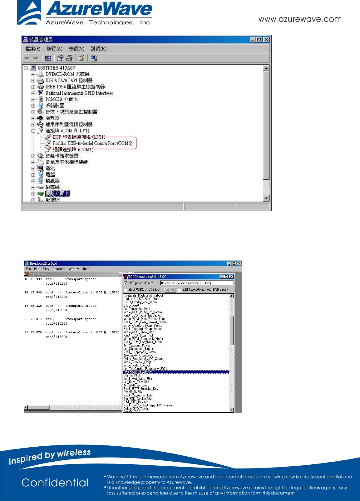
- 10 -
c. In the Baud list, type 115200.
d. Select the CTS flow control check box.
e. Click OK.
5. In HCI Control, select the HCI protocol active check box
6. In the HCI Control commands list, select 0: Vendor-specific Commands (0 key), and then double-click Download
Minidriver.
- 11 -
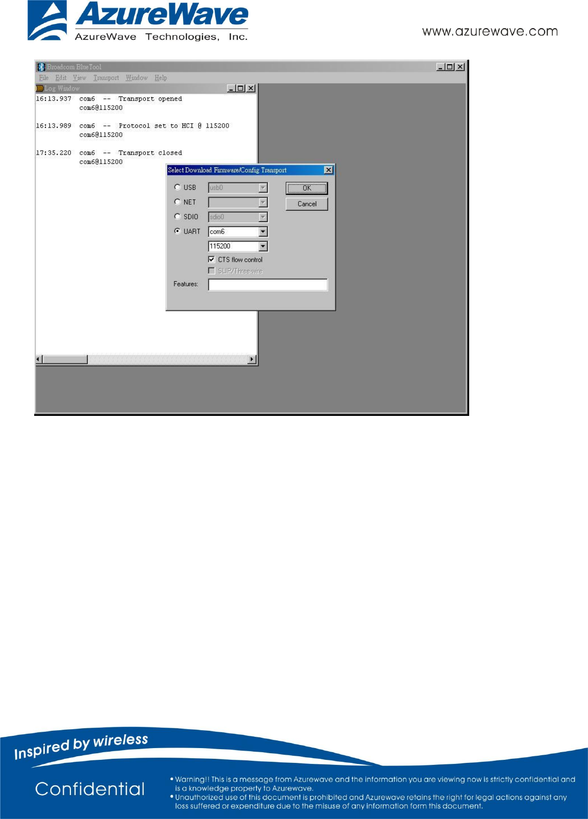
7. On the Transport menu, click Download Firmware/Config.
8. In Select Download Firmware/Config Transport:
a. Select UART as the type of transport.
b. In the COM port list, select com6.
c. In the Baud list box, type 115200.
d. Select the CTS flow control check box.
e. Click OK.
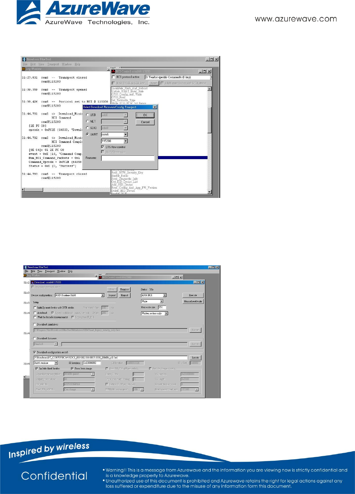
9. In Download, configure the settings to match those shown below
10. Click Execute.
11. Select the HCI protocol active check box

- 12 -
Throughput Test
Bluetool contains a throughput test feature that can be used with two or more AW-NM230NF-H devices. Note that
each device runs on a separate PC with BlueTool installed. This document will provide basic directions for setting-up
and running this test.
The next step in setting-up the test is establishing a connection between the devices.
ESTABLISH A BLUETOOTH CONNECTION BETWEEN TWO USB DEVICES
SET UP THE SLAVE DEVICE FIRST
1. On the Slave side, start Bluetool from the Start Menu.
2. If the Log Window is not already open, select “View” and then select “Log Window”.Select “Transport” and
then Select “HCI Control.” New window pop-up, select “UART” and enter com port number. Click
“OK”.
3. Download mini driver (see 3.1)
4. In the “HCI Control” window, select “7.3 Host Controller & Baseband Commands” (Note: may be 4.3,
depending on version)
5. Double Click the “Write Scan Enable” entry
6. Select “Inquiry and Page Scan Enabled” and click “OK”
7. Double Click “Set Event Filter”
8. Select “Connection Setup”
9. Select “Allow Connections from all devices”
10. Select “Do Auto accept the connection with role switch disabled”
11. Click “OK”
12. In the “HCI Control” window, select “0 Vendor-specific commands”.
13. Double Click the “Write_BD_ADDR” command
14. Enter 001122334455
15. In the “HCI Control” window,select”0 Vendor-specific commands”. Double Click ”Update UART Baud Rate”.
Select 3000000 then click OK.
SET UP THE MASTER DEVICE, AND CREATE THE CONNECTION
1. On the Master side, start Bluetool.
2. Open the log window, if not already open, and open the UART HCI Transport.
3. Download mini driver (see 3.1)
4. In the “HCI Control” window, select “7.1 Link Control Commands” (Note: may be 4.5 depending on version)

- 13 -
5. Double Click “Create Connection” and put BD address of the slave device into the BDADDR box. Click “OK”
6. In the “HCI Control” window,select”0 Vendor-specific commands”. Double Click ”Update UART Baud Rate”.
Select 3000000 then click OK.
A connection should establish now. This can be verified by looking in the log windows for both devices, which should
now contain Connection Complete events with “Success” in the status field.
NOTE: once the connection has been established, Inquiry and Page Scan can be disabled. Also, go to: “7.3 Host
Controller & Baseband Commands” →→ “Set Event Filter”. Select “Connection Setup”; Select “Allow Connections
from all devices”; Select “Do NOT Auto accept the connection” and hit ‘OK’. This will make the slave device
non-discoverable and increase throughput by reducing overhead.
SET UP AND EXECUTE THE THROUGHPUT TEST
SET UP THE SLAVE AS THE RECEIVER
1. On the Slave side, select “Transport” and then select “Throughput Tests”. Select UART.
2. In the “Receive Test” (Bottom half of the window), fill in a data pattern such as “abcdef”, and fill in a count such as
“1000000”
3. Close the “Log Window.” If this window is left open or minimized, then the throughput test will not achieve
maximum throughput because of delay that is added by Windows every time the log window is updated.
SET UP THE MASTER AS THE TRANSMITTER AND START THE TEST
1. On the Master side, select “Transport” and then select “Throughput Tests”. Select UART.
2. In the “Transmit Test” window (top half of the window), fill in the same data pattern and count that was filled in
for the receive test on the Slave side.
3. Close the “Log Window.” If this window is left open or minimized, then the throughput test will not achieve
maximum throughput because of delay that is added by Windows every time the log window is updated.
4. On the Slave side, click “Execute Test” in the “Receive Test” window.
5. On the Master side, click “Execute Test” in the “Transmit Test” window.
Bluetooth throughput test is now running.
To stop the test, click “Abort Test” on the Master side first, then on the slave side.

- 14 -
RF Performance Test
The following procedure explains how to configure the AW-NM230NF-H for RF testing using Broadcom BlueTool. At
the completion of the procedure, connect the Bluetooth test instrument to the AW-NM230NF-H with RF cable and
performs the RF tests.
RESETTING THE USB DEVICE
To reset the USB device
•In HCI Control, in the HCI Control commands list, select 7.3: Host Controller & Baseband Commands (3 key), and
then double-click Reset.
READING THE BLUETOOTH DEVICE ADDRESS
To read the Bluetooth Device Address
• In HCI Control, in the HCI Control commands list, select 7.4: Informational Parameters (4 key), and then double-click
Read_BD_ADDR.
The Bluetooth Device Address (BD_ADDR) is displayed in the log window. The Bluetooth Device Address might be
needed
by the Bluetooth tester
SETTING THE EVENT FILTER TO AUTOMATICALLY ALLOW CONNECTION
To set the event filter to automatically allow connection
1. In HCI Control, in the HCI Control commands list, select 7.3: Host Controller & Baseband Commands (3 key), and
then double-click Set_Event_Filter.
2. In HCI Command: Set_Event_Filter:
a. In the Filter_Type list, select Connection Setup.
b. In the Connection_Setup_Filter_Condition_Type list, select Allow Connections from all devices.
c. In the Auto_Accept_Flag list, select Do Auto accept the connection with role switch disabled.
ENABLING WRITE SCAN
To enable Write Scan
1. In HCI Control, in the HCI Control commands list, select 7.3: Host Controller & Baseband Commands (3 key), and
then double-click Write_Scan_Enable.
2. In HCI Command: Write_Scan_Enable, in the Scan_Enable list, select Inquiry and Page Scan enabled.
ENABLING TEST MODE

- 15 -
To enable Test Mode
• In HCI Control, in the HCI Control commands list, select 7.6: Testing Commands (6 key), and then double-click
Enable_Device_Under_Test_Mode.
The AW-NM230NF-H is now ready to receive a connection request from the Bluetooth tester and begin testing
specified RF parameters.
3.Statement
Federal Communication Commission Interference Statement
This equipment has been tested and found to comply with the limits for a Class B digital device, pursuant to Part 15 of
the FCC Rules. These limits are designed to provide reasonable protection against harmful interference in a residential
installation. This equipment generates, uses and can radiate radio frequency energy and, if not installed and used in
accordance with the instructions, may cause harmful interference to radio communications. However, there is no
guarantee that interference will not occur in a particular installation. If this equipment does cause harmful
interference to radio or television reception, which can be determined by turning the equipment off and on, the user
is encouraged to try to correct the interference by one of the following measures:
- Reorient or relocate the receiving antenna.
- Increase the separation between the equipment and receiver.
- Connect the equipment into an outlet on a circuit different from that
to which the receiver is connected.
- Consult the dealer or an experienced radio/TV technician for help.
FCC Caution: Any changes or modifications not expressly approved by the party responsible for compliance could void
the user's authority to operate this equipment.
This device complies with Part 15 of the FCC Rules. Operation is subject to the following two conditions: (1) This device
may not cause harmful interference, and (2) this device must accept any interference received, including interference
that may cause undesired operation.
IMPORTANT NOTE:
Radiation Exposure Statement:
This equipment complies with FCC radiation exposure limits set forth for an uncontrolled environment. This equipment
should be installed and operated with minimum distance 20cm between the radiator & your body.
This transmitter must not be co-located or operating in conjunction with any other antenna or transmitter.
Country Code selection feature to be disabled for products marketed to the US/CANADA

- 16 -
This device is intended only for OEM integrators under the following conditions:
1) The antenna must be installed such that 20 cm is maintained between the antenna and users, and
2) The transmitter module may not be co-located with any other transmitter or antenna,
3) For all products market in US, OEM has to limit the operation channels in CH1 to CH11 for 2.4G band by
supplied firmware programming tool. OEM shall not supply any tool or info to the end-user regarding to
Regulatory Domain change.
As long as 3 conditions above are met, further transmitter test will not be required. However, the OEM integrator is
still responsible for testing their end-product for any additional compliance requirements required with this module
installed
IMPORTANT NOTE
In the event that these conditions can not be met (for example certain laptop configurations or co-location with
another transmitter), then the FCC authorization is no longer considered valid and the FCC ID can not be used on the
final product. In these circumstances, the OEM integrator will be responsible for re-evaluating the end product
(including the transmitter) and obtaining a separate FCC authorization.
End Product Labeling
This transmitter module is authorized only for use in device where the antenna may be installed such that 20 cm may
be maintained between the antenna and users. The final end product must be labeled in a visible area with the
following: “Contains FCC ID: TLZ-NM230NF”.
Manual Information to the End User
The OEM integrator has to be aware not to provide information to the end user regarding how to install or remove
this RF module in the user’s manual of the end product which integrates this module.
The end user manual shall include all required regulatory information/warning as show in this manual.

- 17 -
Industry Canada statement:
This device complies with Industry Canada’s licence-exempt RSSs. Operation is subject to the following two conditions:
(1) This device may not cause interference; and (2) This device must accept any interference, including interference
that may cause undesired operation of the device.
Cet appareil est conforme aux CNR exemptes de licence d'Industrie Canada. Son fonctionnement est soumis aux deux
conditions suivantes:
(1) Ce dispositif ne peut causer d'interférences; et(2) Ce dispositif doit accepter toute interférence, y compris les
interférences qui peuvent causer un mauvais fonctionnement de l'appareil.
Radiation Exposure Statement:
This equipment complies with IC radiation exposure limits set forth for an uncontrolled environment. This equipment
should be installed and operated with minimum distance 20cm between the radiator & your body.
Déclaration d'exposition aux radiations:
Cet équipement est conforme aux limites d'exposition aux rayonnements IC établies pour un environnement non
contrôlé. Cet équipement doit être installé et utilisé avec un minimum de 20 cm de distance entre la source de
rayonnement et votre corps.

- 18 -
This device is intended only for OEM integrators under the following conditions:
1) The antenna must be installed such that 20 cm is maintained between the antenna and users, and
2) The transmitter module may not be co-located with any other transmitter or antenna.
As long as 2 conditions above are met, further transmitter test will not be required. However, the OEM integrator is
still responsible for testing their end-product for any additional compliance requirements required with this module
installed.
Cet appareil est conçu uniquement pour les intégrateurs OEM dans les conditions suivantes:
1) L'antenne doit être installée de telle sorte qu'une distance de 20 cm est respectée entre l'antenne et les utilisateurs,
et
2) Le module émetteur peut ne pas être coïmplanté avec un autre émetteur ou antenne.
Tant que les 2 conditions ci-dessus sont remplies, des essais supplémentaires sur l'émetteur ne seront pas nécessaires.
Toutefois, l'intégrateur OEM est toujours responsable des essais sur son produit final pour toutes exigences de
conformité supplémentaires requis pour ce module installé.
IMPORTANT NOTE:
In the event that these conditions can not be met (for example certain laptop configurations or co-location with
another transmitter), then the Canada authorization is no longer considered valid and the IC ID can not be used on the
final product. In these circumstances, the OEM integrator will be responsible for re-evaluating the end product
(including the transmitter) and obtaining a separate Canada authorization.
NOTE IMPORTANTE:
Dans le cas où ces conditions ne peuvent être satisfaites (par exemple pour certaines configurations d'ordinateur
portable ou de certaines co-localisation avec un autre émetteur), l'autorisation du Canada n'est plus considéré comme
valide et l'ID IC ne peut pas être utilisé sur le produit final. Dans ces circonstances, l'intégrateur OEM sera chargé de
réévaluer le produit final (y compris l'émetteur) et l'obtention d'une autorisation distincte au Canada.
End Product Labeling
This transmitter module is authorized only for use in device where the antenna may be installed such that 20 cm may
be maintained between the antenna and users. The final end product must be labeled in a visible area with the
following: “Contains IC: 6100A-NM230NF”.
- 19 -
Plaque signalétique du produit final
Ce module émetteur est autorisé uniquement pour une utilisation dans un dispositif où l'antenne peut être installée
de telle sorte qu'une distance de 20cm peut être maintenue entre l'antenne et les utilisateurs. Le produit final doit
être étiqueté dans un endroit visible avec l'inscription suivante: "Contient des IC: 6100A-NM230NF ".
Manual Information To the End User
The OEM integrator has to be aware not to provide information to the end user regarding how to install or remove
this RF module in the user’s manual of the end product which integrates this module.
The end user manual shall include all required regulatory information/warning as show in this manual.
Manuel d'information à l'utilisateur final
L'intégrateur OEM doit être conscient de ne pas fournir des informations à l'utilisateur final quant à la façon d'installer
ou de supprimer ce module RF dans le manuel de l'utilisateur du produit final qui intègre ce module.
Le manuel de l'utilisateur final doit inclure toutes les informations réglementaires requises et avertissements comme
indiqué dans ce manuel.
This radio transmitter (IC: 6100A-NM230NF) has been approved by Industry Canada to operate with the antenna types
listed below with the maximum permissible gain indicated. Antenna types not included in this list, having a gain
greater than the maximum gain indicated for that type, are strictly prohibited for use with this device
Cet émetteur radio (IC: 6100A-NM230NF) a été approuvé par Industrie Canada pour fonctionner avec les types
d'antenne énumérés ci-dessous avec le gain maximal admissible indiqué. Types d'antennes ne figurent pas dans cette
liste, ayant un gain supérieur au gain maximum indiqué pour ce type, sont strictement interdits pour une utilisation
avec cet appareil
Model
Type
Connector
Gain (dBi)
RFMTA340715IMLB301
PIFA
I-PEX
3

- 20 -
Taiwan 警語:
第十二條→經型式認證合格之低功率射頻電機,非經許可,公司,商號或使用者均不得擅自變更頻率、加大功
率或變更原設計之特性及功能。
第十四條→低功率射頻電機之使用不得影響飛航安全及干擾合法通信;經發現有干擾現象時,應立即停用,並
改善至無干擾時方得繼續使用。
前項合法通信,指依電信法規定作業之無線電通信。 低功率射頻電機須忍受合法通信或工業、科學及醫療用電
波輻射性電機設備之干擾。
1. 本模組於取得認證後將依規定於模組本體標示審驗合格標籤
2. 系統廠商應於平台上標示「本產品內含射頻模組:
CC XX xx YY yyy Z z W」字樣

- 21 -
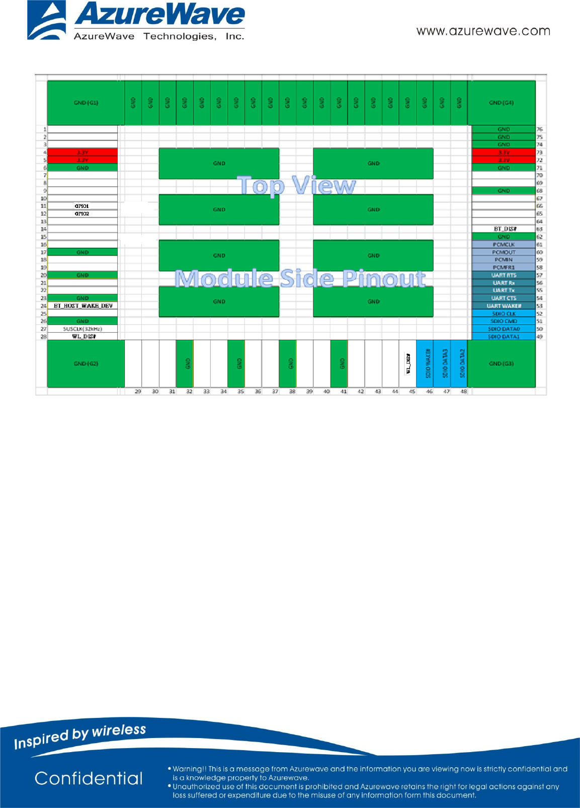
4. Pin Definition / Pin Map
Pin
No
Definition
Basic Description
Type
Voltag
e
1
NC
No Connect
Floating
2
NC
No Connect
Floating
3
NC
No Connect
Floating
4
3.3V
3.3V power pin
VCC
3.3V
5
3.3V
3.3V power pin
VCC
3.3V
6
GND
Ground.
GND
7
NC
No Connect
Floating
8
NC
No Connect
Floating
9
NC
No Connect
Floating
10
NC
No Connect
Floating
11
GPIO1
GPIO pin
I/O
3.3V
12
GPIO2
GPIO pin
I/O
3.3V
13
NC
No Connect
Floating
14
NC
No Connect
Floating
15
NC
No Connect
Floating
16
NC
No Connect
Floating
17
GND
Ground.
GND
18
NC
No Connect
Floating
19
NC
No Connect
Floating
20
GND
Ground.
GND
21
NC
No Connect
Floating
22
NC
No Connect
Floating
23
GND
Ground
GND
24
BT_HOST_WAKE_DE
V
BT Device Wake
I
3.3V
25
NC
No Connect
Floating
26
GND
Ground
GND
27
SUSCLK(32kHz)
External sleep clock input (32.768 kHz).
I
3.3V
28
WL_DIS#
Used by PMU to power up or power down the
internal regulators used by the WLAN section.
Also, when deasserted, this pin holds the WLAN
I
3.3V

- 22 -
section in reset. This pin has an internal 200k
ohm pull down resistor that is enabled by
default. It can be disabled through programming.
29
NC
No Connect
Floating
30
NC
No Connect
Floating
31
NC
No Connect
Floating
32
GND
Ground
GND
33
NC
No Connect
Floating
34
NC
No Connect
Floating
35
GND
Ground
GND
36
NC
No Connect
Floating
37
NC
No Connect
Floating
38
GND
Ground
GND
39
NC
No Connect
Floating
40
NC
No Connect
Floating
41
GND
Ground
GND
42
NC
No Connect
Floating
43
NC
No Connect
Floating
44
NC
No Connect
Floating
45
WL_DIS#
Used by PMU to power up or power down the
internal regulators used by the WLAN section.
Also, when deasserted, this pin holds the WLAN
section in reset. This pin has an internal 200k
ohm pull down resistor that is enabled by
default. It can be disabled through programming.
I
3.3V
46
WL_DEV_WAKE_HO
ST
WL Host Wake
O
3.3V
47
SDIO_D3
SDIO Data Line 3
I/O
3.3V
48
SDIO_D2
SDIO Data Line 2
I/O
3.3V
49
SDIO_D1
SDIO Data Line 1
I/O
3.3V
50
SDIO_D20
SDIO Data Line 0
I/O
3.3V
51
SDIO_CMD
SDIO Command Input
I/O
3.3V
52
SDIO_CLK
SDIO Clock Input
I
3.3V
53
BT_DEV_WAKE_HOS
T
BT Host Wake
O
3.3V

- 23 -
54
UART_CTS
High-Speed UART CTS
I
3.3V
55
UART_OUT
High-Speed UART Data Out
O
3.3V
56
UART_IN
High-Speed UART Data In
I
3.3V
57
UART_RTS
High-Speed UART RTS
O
3.3V
58
PCM_SYNC
PCM Synchronization control
O
3.3V
59
PCM_IN
PCM data Input
I
3.3V
60
PCM_OUT
PCM data Out
O
3.3V
61
PCM_CLK
PCM Clock
I/O
3.3V
62
GND
Ground
GND
63
BT_DIS#
Used by PMU to power up or power down the
internal regulators used by the Bluetooth
section. Also, when deasserted, this pin holds the
Bluetooth section in reset. This pin has an
internal 200k ohm pull down resistor that is
enabled by default. It can be disabled through
programming.
I
3.3V
64
NC
No Connect
Floating
65
NC
No Connect
Floating
66
NC
No Connect
Floating
67
NC
No Connect
Floating
68
GND
Ground
GND
69
NC
No Connect
Floating
70
NC
No Connect
Floating
71
GND
Ground
GND
72
3.3V
3.3V power pin
VCC
3.3V
73
3.3V
3.3V power pin
VCC
3.3V
74
GND
Ground
GND
75
GND
Ground
GND
76
GND
Ground
GND
77
GND
Ground
GND
78
GND
Ground
GND
79
GND
Ground
GND
80
GND
Ground
GND
81
GND
Ground
GND
82
GND
Ground
GND

- 24 -
83
GND
Ground
GND
84
GND
Ground
GND
85
GND
Ground
GND
86
GND
Ground
GND
87
GND
Ground
GND
88
GND
Ground
GND
89
GND
Ground
GND
90
GND
Ground
GND
91
GND
Ground
GND
92
GND
Ground
GND
93
GND
Ground
GND
94
GND
Ground
GND
95
GND
Ground
GND
96
GND
Ground
GND
G1
GND
Ground
GND
G2
GND
Ground
GND
G3
GND
Ground
GND
G4
GND
Ground
GND
G5
GND
Ground
GND
G6
GND
Ground
GND
G7
GND
Ground
GND
G8
GND
Ground
GND
G9
GND
Ground
GND
G10
GND
Ground
GND
G11
GND
Ground
GND
G12
GND
Ground
GND
- 25 -
AW-NM230NF-H Top View Pin Map