AzureWave Technologies NM387 IEEE 802.11b/g/n Wireless LAN & Bluetooth Module User Manual AW NM387 DS v0 4
AzureWave Technologies, Inc. IEEE 802.11b/g/n Wireless LAN & Bluetooth Module AW NM387 DS v0 4
UserManual.wiki
>
AzureWave Technologies
>
NM387 User Manual
User Manual
Navigation menu
Upload a User Manual
Namespaces
Wiki Guide
HTML
PDF
Info
Views
User Manual
Discussion / Help
Navigation
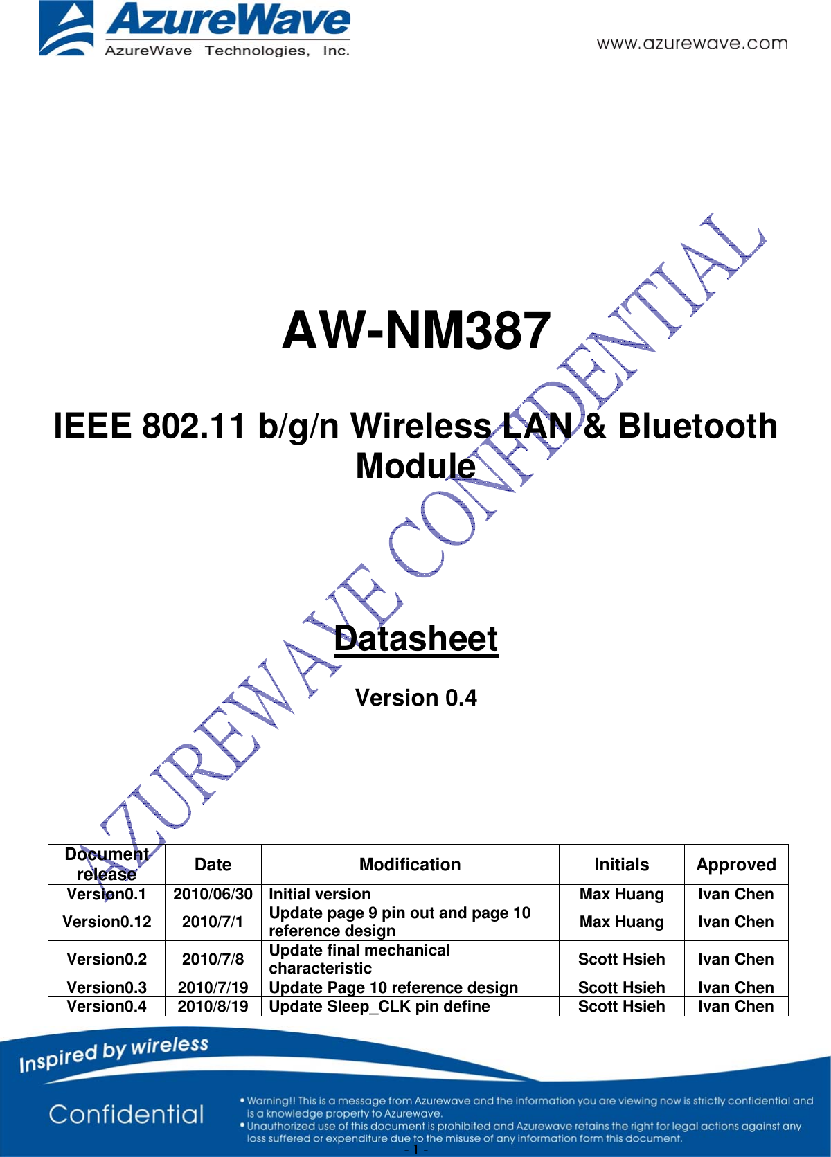
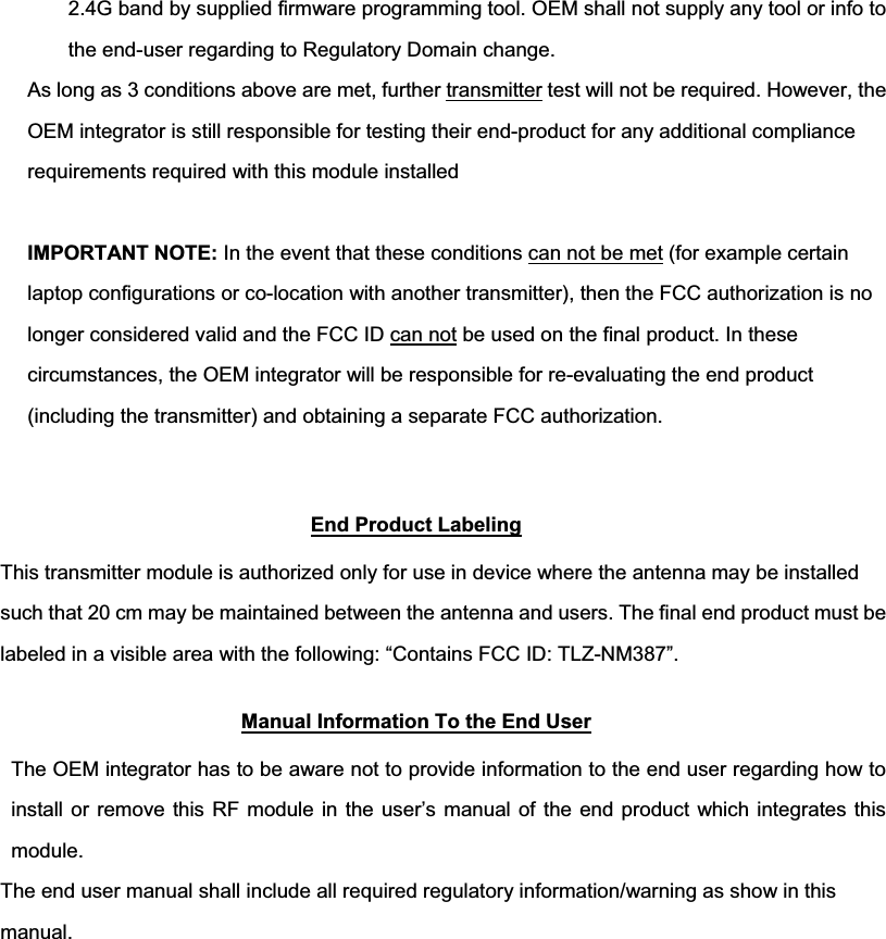
![- 8 - SDIO Timing Data Symbol Parameter Condition Min Typ Max Units fpp CLK Frequency Normal 0 25 MHz High Speed 0 75 TWH CLK High Time Normal 10 ns High Speed 7 TWL CLK Low Time Normal 10 High Speed 7 TISU Input Setup Time Normal 5 High Speed 6 TIH Input Hold Time Normal 5 High Speed 2 TODLY Output Delay Time 0 7.33 TOH Output Hold Time High Speed 2.5 2-5. Pin Out Power Supply Use VIO PDn SD_CLK SD_CMD SD_DAT[1] SD_DAT[2] SD_DAT[3] WiFi_LED BT_LED](https://usermanual.wiki/AzureWave-Technologies/NM387/User-Guide-1417808-Page-8.png)
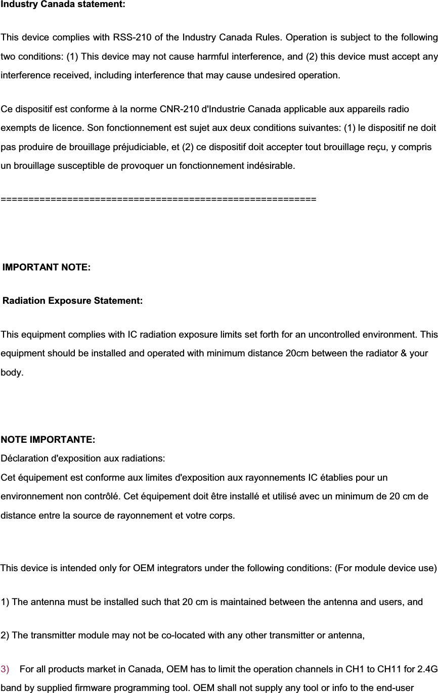
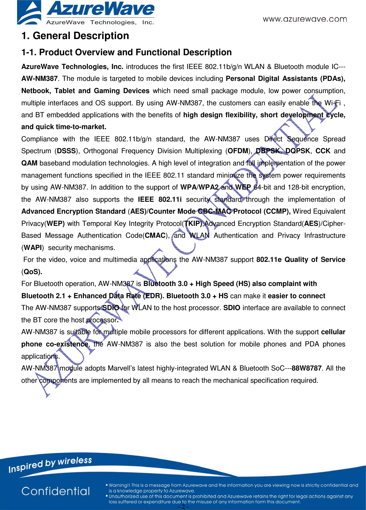
![- 9 - 3. Pin Definition Pin Assignment Pin No Definition Basic Description Type 1 GND 2 External 1.8V(optional) 1.8V voltage optional. Default model is used internal 1.8V, so please keep this pin float. If the customer wants to use external 1.8V model. Please contact to AzureWave. P 3 PDn Full Power Down(active low as long as system need) 0=power down mode 1=normal mode (1)Connect to power down pin of host Note: Needs the external host to driver this pin high for normal operation. No internal pull-up on this pin. I 4 VIO 1.8V/2.6/3.3V Host interface voltage P 5 SLEEP_CLK Sleep Clock Input Used for WALN, Bluetooth, and FM low-power modes. External sleep clock of 32.768KHZ must be used for auto reference clock calibration and for WALN/Bluetooth/FM low power operation. I 6 GND 7 SD_CMD SDIO 4-bit Mode: Command/Response SDIO 1-bit Mode: Command Line SDIO SPI Mode: Data Input I/O 8 SD_DAT[0] SDIO 4-bit Mode: Data line bit[0] SDIO 1-bit Mode: Data line SDIO SPI Mode: Data output I 9 SD_DAT[1] SDIO 4-bit Mode: Data line bit[1] SDIO 1-bit Mode: Interrupt SDIO SPI Mode: Reserved I/O 10 SD_DAT[2] SDIO4-bit Mode: Data line bit[2]or Read Wait(optional) SDIO 1-bit Mode: Read Wait(optional) SDIO SPI Mode: Reserved I/O 11 SD_CLK SDIO 4-bit Mode: Clock Input SDIO 1-bit Mode: Clock Input SDIO SPI Mode: Clock Input I/O 12 SD_DAT[3] SDIO 4-bit Mode: Data line bit[3] SDIO 1-bit Mode: Reserved SDIO SPI Mode: Card Select(active low) I/O 13 WIFI_LED/GPIO1 WIFI LED function I/O 14 BT_LED/GPIO 17 BT LED function I/O 15 3.3V P 16 3.3V P 17 GND](https://usermanual.wiki/AzureWave-Technologies/NM387/User-Guide-1417808-Page-9.png)