AzureWave Technologies NM388 IEEE 802.11 b/g/n Wireless LAN & Bluetooth Module User Manual AW GM320
AzureWave Technologies, Inc. IEEE 802.11 b/g/n Wireless LAN & Bluetooth Module AW GM320
UserMan_TLZ-NM388
- 1 -
AW-NM388
Wireless LAN & Bluetooth Module IC
For Mobile Phones, DSCs, PMPs and Gaming Devices
XP MFG Tool Command User Guide
Version 0.2
Document
release
Date
Modification
Initials
Approved
Ver. 0.1
2011/07/05
Initial version
Lester Huang
Ivan Chen
Ver. 0.2
2012/01/31
Add Warning Statement
Lester Huang
Ivan Chen
- 2 -
1. AW-NM388 WLAN & Bluetooth MFG Tool Command User Guide
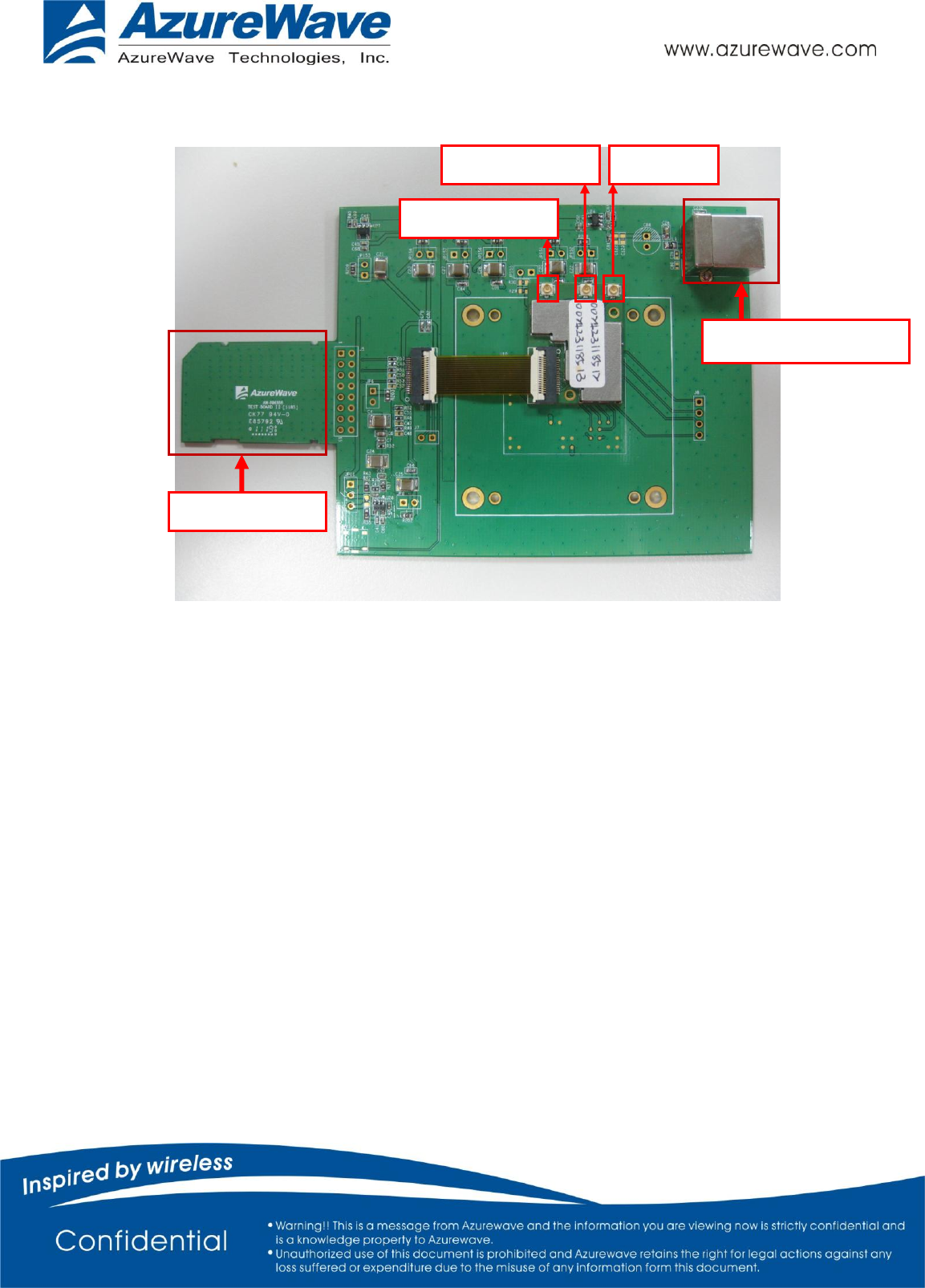
Figur1
When you test AW-NM388, AW-NM388 module put in socket and please connect the B type
USB. It is necessary for two issues. One is for Bluetooth UART to USB interface control and
the other one is apply the voltage for 32.768KHz OSC.
1.1 Step1: Environment set up(Win XP English Ver. is necessary)
(1) Plug the USB cable in the host PC.
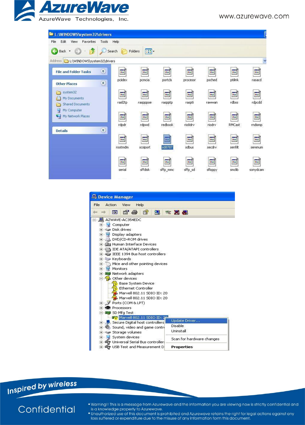
(2) Copy the file “sd8787.sys” from the sub folder below:
\MFG-8787-WIFI-SD-BT-SD-WIN-X86-1.2.6.22-14.0.3.p155\bin\lab_tool\drv\WinXP
(Please contact Azurewave FAE for the sub folder) and phase it into the sub folder below:
\Windows\system32\drivers
As figure 2
BT Antenna
B Type USB connector
WIFI AUX Antenna
Antenna Port
WIFI Main Antenna
SDIO Interface
- 3 -
Figure 2
Figure 3
- 4 -
(3) Connect SDIO to the host PC.
(4) Choose “Cancel” for all auto hardware detection.
(5) Install the 8787 SDIO driver following the steps below:
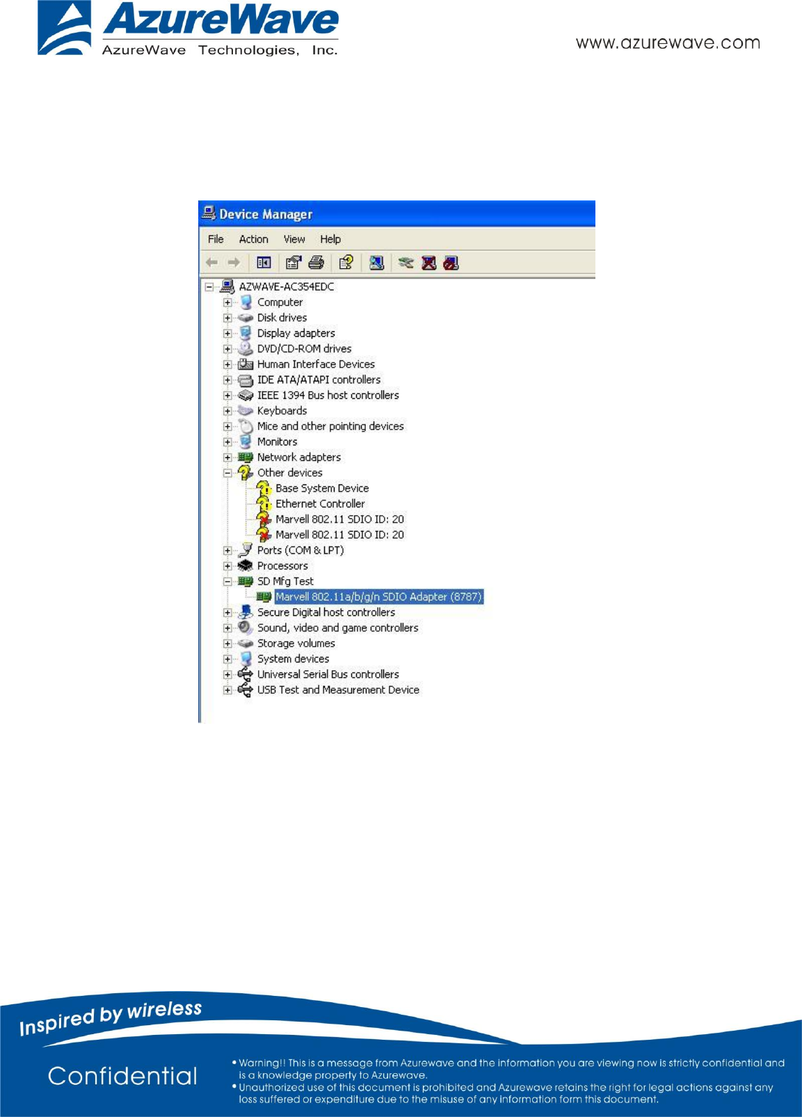
1. Refer to Figure 3 for the indication of the 8787 device in the Windows Device manager.
2. At this point the host PC will auto detect 3 Marvell 802.11 SDIO devices.
3. Only one Marvell 802.11 SDIO is work, others can be ignored.
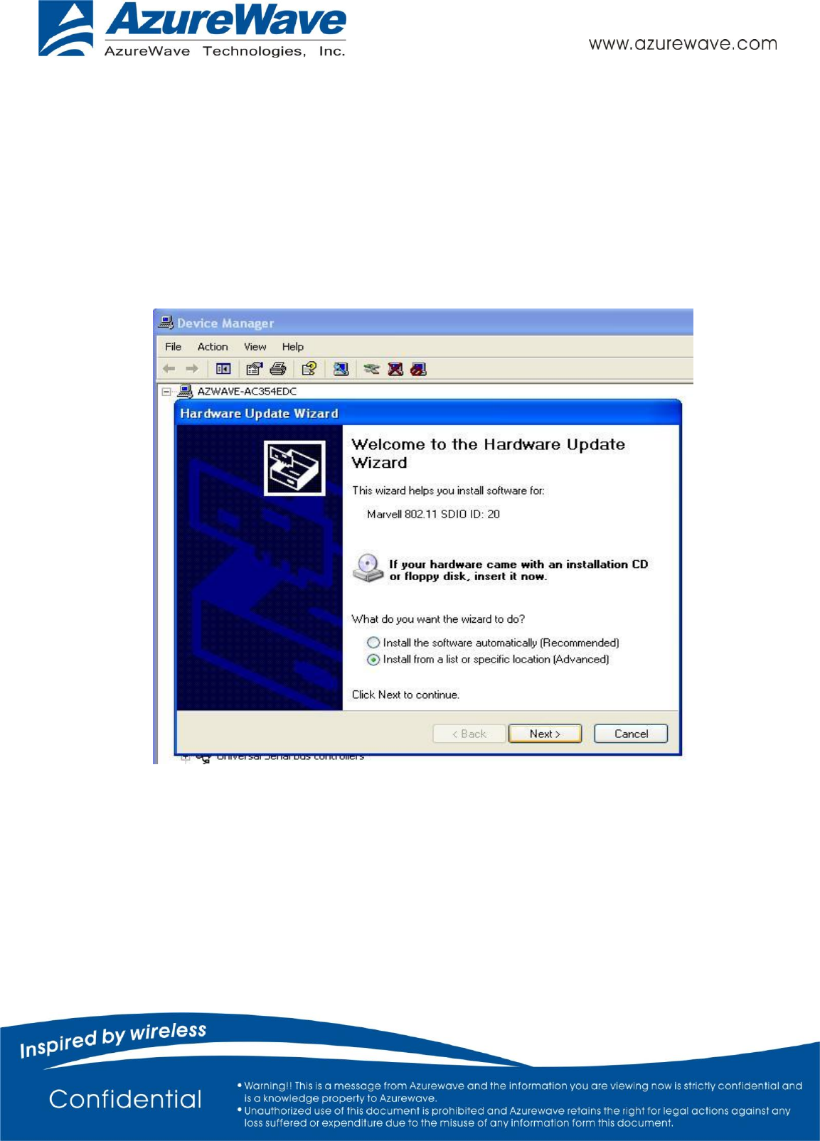
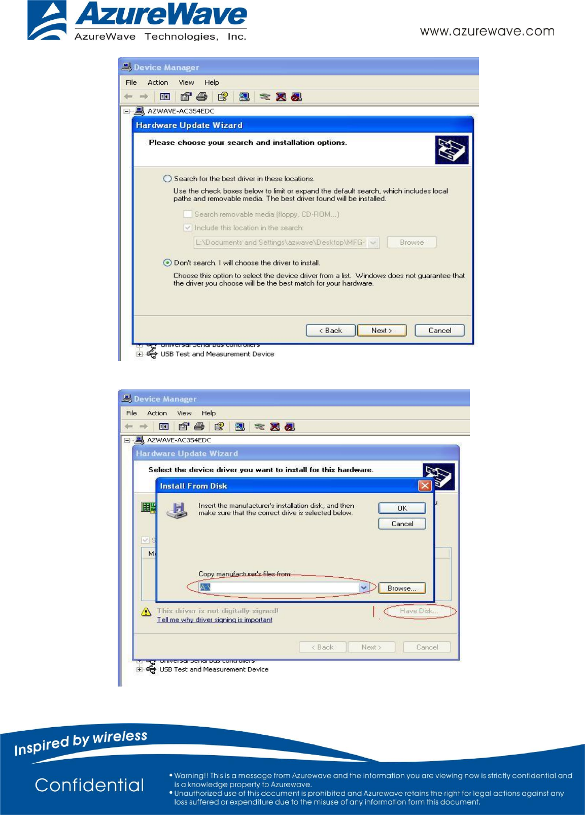
4. Update Driver following the picture below
Figure 4
- 5 -
Figure 5
Figure 6
- 6 -
5. Browse the driver from the folder as below: (Figure 6)
\MFG-8787-WIFI-SD-BT-SD-WIN-X86-1.2.6.22-14.0.3.p155\bin\lab_tool\drv\WinXP
6. Installation will be successful as Figure 7 showed. WiFi is done.
Figure 7
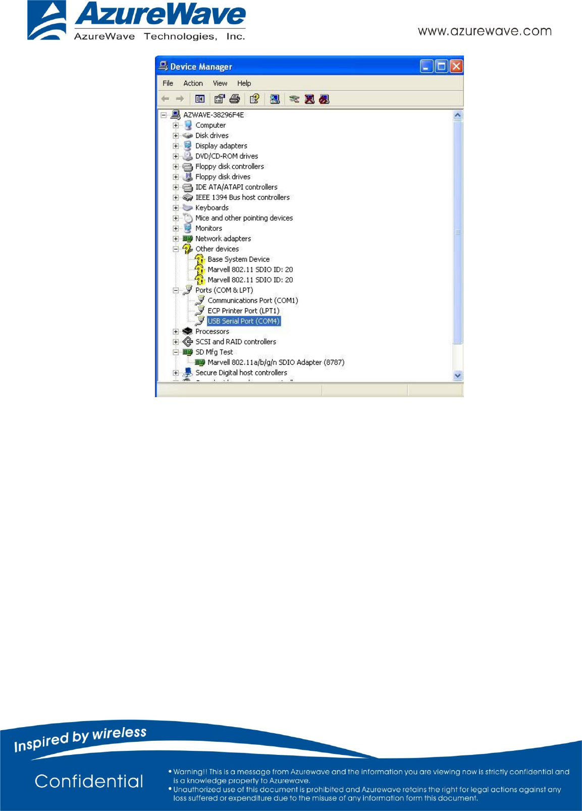
7. Setup Bluetooth UART to USB driver. FTDI IC is used in this adapter board.
8. Please indicated the install path to the FTDI folder (Check Azurewave FAE to get this one)
9. After installing, you can find the new comport showing up in the devices manager as figure 8.
- 7 -
Figure 8
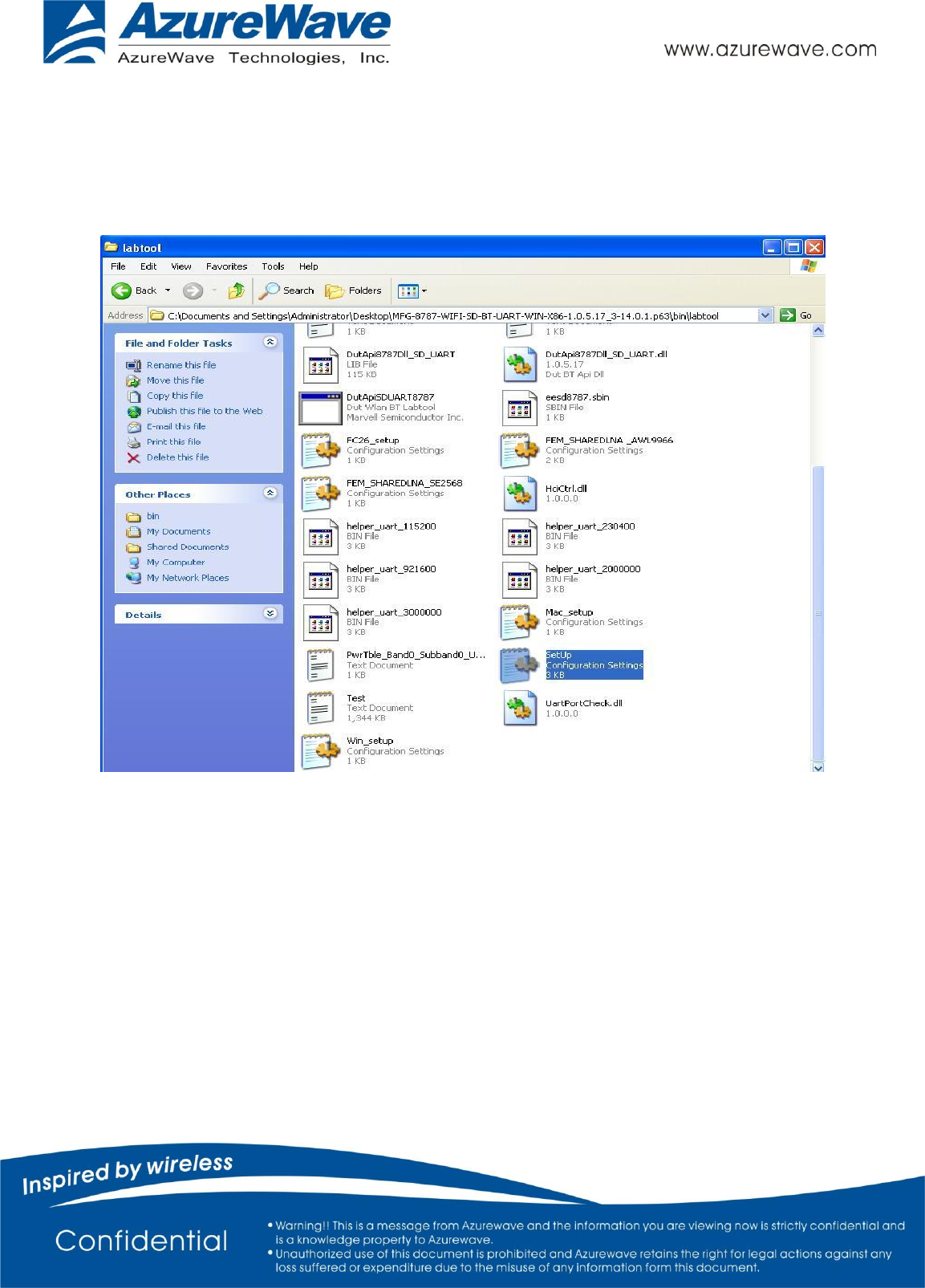
1.2 Step2: Opening MFG Tool
(1) Please make sure the AW-NM388 is enabling (check OS device manger).
(2) Opening MFG tool, please double click on the “DutApiSDUART8787.exe.” in this sub folder:
(3) \ MFG-8787-WIFI-SD-BT-SD-WIN-X86-1.2.6.22-14.0.3.p155\bin\labtool
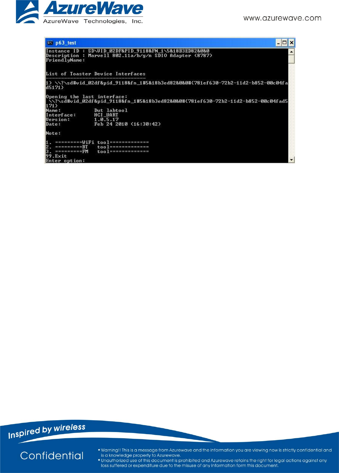
1.3 Step3: Initial Command
As the information showed on your screen, please enter these commands below to start your test.
(Figure 9)
Command: 1 Wi-Fi testing mode
Command: 2 BT testing mode
Command: 3 FM testing mode
- 8 -
Figure 9
1.3 Step3: Generate 802.11 b/g/n Packet
(1)Command:
Select WIFI Main Antenna:
69 90000200 40
69 90000208 0
69 9000020C 8
69 80002200 FFFF
Select WIFI AUX Antenna:
69 90000200 400
69 90000208 0
69 9000020C 20
69 80002200 FFFF
(2)Command: 22 1 12 1
22: Initial transmit power in the antenna
1: Set the wanted channel (1~14 for B/G/N mode)
12: Set the wanted power, typically G mode: 12 dBm/ B mode: 15 dBm
1: Set the mode, 1G mode & N mode , 0 B mode
- 9 -
(3)Command: 112 0 (only for N mode)
112: N mode HT20/40.
0: for HT20/40. 0HT20, 1HT40
(4)Command: 25 1 13
25: Set duty cycle, packet mode.
1: Data rate enable
13: Data rate set up
A mode &B mode & G mode
1Mbps
5.5Mbps
11Mbps
6Mbps
9Mbps
12Mbps
18Mbps
24Mbps
1
3
4
6
7
8
9
10
36Mbps
48Mbps
54Mbps
11
12
13
N mode
MCS0
MCS1
MCS2
MCS3
MCS4
MCS5
MCS6
MCS7
MCS8
15
16
17
18
19
20
21
22
23
After you type above command, you can measure the 802.11b/g/n packet by your RF test instrument (exp:
Agilent 4010, IQview…).
(5) Command: 25 0
Stop transmitting packet signal.
1.4 Step4: Generate 802.11b/g/n continuous symbol
(1)Please re-type the Step3 (1)~(5) commands.
(2)Command 17 1 13
17: Set continuous mode.
1: Enable data rate
13: 54 Mbps, other data rate, please refer the above table.
After you type above command, you can measure the 802.11b/g continuous symbol in your RF test
instrument.
(3)Command 17 0
Stop transmitting continuous signal

- 10 -
1.5 Step5: Test RX sensitivity
Before test RX, the Marvell standard waveform is needed. Please contact
Azurewave FAE for this issue.
(1)Command:
Select WIFI Main Antenna:
69 90000200 40
69 90000208 0
69 9000020C 8
69 80002200 FFFF
Select WIFI AUX Antenna:
69 90000200 400
69 90000208 0
69 9000020C 20
69 80002200 FFFF
(2) Command 12 1
12: Choose RX text channel
1: Channel number, (1~14 for B/G/N mode)
(3) Command: 112 0 (only for N mode)
112: N mode HT20/40.
0: for HT20/40. 0HT20, 1HT40
(4) 31: Clear all the received packets.
(6) 32: Check the received packets.
1.6 Others Commands
(1) Command 45 Check the MAC
(2) Command 99 Quit the test mode/ Quit the MFG tool
- 11 -
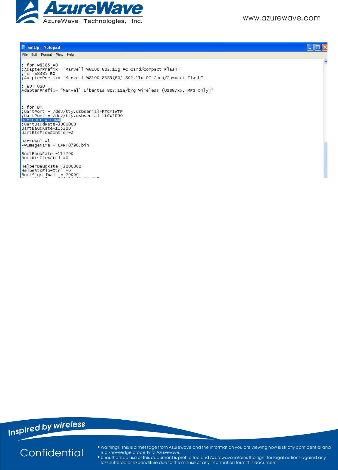
1.7 BT test mode Commands
When you begin to test Bluetooth, please make sure your com port is correct. Please open the “setup.ini”
file which is under:
\ MFG-8787-WIFI-SD-BT-SD-WIN-X86-1.2.6.22-14.0.3.p155\bin\labtool
As Figure 10.
Figure 10
Find the BT COM port and make sure the com port is corresponding to the device manager.
- 12 -
As Figure 11.
Figure 11
(1) Command 45Check BT MAC.
(2) Command 78 1BT enter test mode.
After you type above command, you can measure BT signal both TX/RX and the other BT test items by
your BT instrument.

- 13 -
Federal Communication Commission Interference Statement
This device complies with Part 15 of the FCC Rules. Operation is subject to the following two
conditions: (1) This device may not cause harmful interference, and (2) this device must accept
any interference received, including interference that may cause undesired operation.
This equipment has been tested and found to comply with the limits for a Class B digital device,
pursuant to Part 15 of the FCC Rules. These limits are designed to provide reasonable protection
against harmful interference in a residential installation. This equipment generates, uses and can
radiate radio frequency energy and, if not installed and used in accordance with the instructions,
may cause harmful interference to radio communications. However, there is no guarantee that
interference will not occur in a particular installation. If this equipment does cause harmful
interference to radio or television reception, which can be determined by turning the equipment
off and on, the user is encouraged to try to correct the interference by one of the following
measures:
- Reorient or relocate the receiving antenna.
- Increase the separation between the equipment and receiver.
- Connect the equipment into an outlet on a circuit different from that
to which the receiver is connected.
- Consult the dealer or an experienced radio/TV technician for help.
FCC Caution: Any changes or modifications not expressly approved by the party responsible for
compliance could void the user's authority to operate this equipment.
This transmitter must not be co-located or operating in conjunction with any other antenna or
transmitter.
Radiation Exposure Statement:
This equipment complies with FCC radiation exposure limits set forth for an uncontrolled
environment. This equipment should be installed and operated with minimum distance 20cm
between the radiator & your body.
- 14 -
This device is intended only for OEM integrators under the following conditions:
1) The antenna must be installed such that 20 cm is maintained between the antenna and users, and
2) The transmitter module may not be co-located with any other transmitter or antenna.
As long as 2 conditions above are met, further transmitter test will not be required. However, the
OEM integrator is still responsible for testing their end-product for any additional compliance
requirements required with this module installed
IMPORTANT NOTE: In the event that these conditions can not be met (for example certain
laptop configurations or co-location with another transmitter), then the FCC authorization is no
longer considered valid and the FCC ID can not be used on the final product. In these circumstances,
the OEM integrator will be responsible for re-evaluating the end product (including the transmitter)
and obtaining a separate FCC authorization.
End Product Labeling
This transmitter module is authorized only for use in device where the antenna may be installed such
that 20 cm may be maintained between the antenna and users. The final end product must be labeled
in a visible area with the following: “Contains FCC ID: TLZ-NM388”. The grantee's FCC ID can be
used only when all FCC compliance requirements are met.
Manual Information To the End User
The OEM integrator has to be aware not to provide information to the end user regarding how to install or
remove this RF module in the user’s manual of the end product which integrates this module.
The end user manual shall include all required regulatory information/warning as show in this
manual.
Industry Canada statement:
This device complies with RSS-210 of the Industry Canada Rules. Operation is subject to the following
two conditions: (1) This device may not cause harmful interference, and (2) this device must accept any
interference received, including interference that may cause undesired operation.
Ce dispositif est conforme à la norme CNR-210 d'Industrie Canada applicable aux appareils radio
exempts de licence. Son fonctionnement est sujet aux deux conditions suivantes: (1) le dispositif ne doit
pas produire de brouillage préjudiciable, et (2) ce dispositif doit accepter tout brouillage reçu, y compris
un brouillage susceptible de provoquer un fonctionnement indésirable.
- 15 -
Radiation Exposure Statement:
This equipment complies with IC radiation exposure limits set forth for an uncontrolled environment.
This equipment should be installed and operated with minimum distance 20cm between the radiator &
your body.
Déclaration d'exposition aux radiations:
Cet équipement est conforme aux limites d'exposition aux rayonnements IC établies pour un
environnement non contrôlé. Cet équipement doit être installé et utilisé avec un minimum de 20 cm de
distance entre la source de rayonnement et votre corps.
This device is intended only for OEM integrators under the following conditions: (For module device use)
1) The antenna must be installed such that 20 cm is maintained between the antenna and users, and
2) The transmitter module may not be co-located with any other transmitter or antenna.
As long as 2 conditions above are met, further transmitter test will not be required. However, the OEM
integrator is still responsible for testing their end-product for any additional compliance requirements
required with this module installed.
Cet appareil est conçu uniquement pour les intégrateurs OEM dans les conditions suivantes: (Pour
utilisation de dispositif module)
1) L'antenne doit être installée de telle sorte qu'une distance de 20 cm est respectée entre l'antenne et les utilisateurs, et
2) Le module émetteur peut ne pas être coïmplanté avec un autre émetteur ou antenne.
Tant que les 2 conditions ci-dessus sont remplies, des essais supplémentaires sur l'émetteur ne seront pas
nécessaires. Toutefois, l'intégrateur OEM est toujours responsable des essais sur son produit final pour
toutes exigences de conformité supplémentaires requis pour ce module installé.
IMPORTANT NOTE:
In the event that these conditions can not be met (for example certain laptop configurations or co-location
with another transmitter), then the Canada authorization is no longer considered valid and the IC ID can
not be used on the final product. In these circumstances, the OEM integrator will be responsible for
re-evaluating the end product (including the transmitter) and obtaining a separate Canada authorization.
NOTE IMPORTANTE:
Dans le cas où ces conditions ne peuvent être satisfaites (par exemple pour certaines configurations
d'ordinateur portable ou de certaines co-localisation avec un autre émetteur), l'autorisation du Canada
- 16 -
n'est plus considéré comme valide et l'ID IC ne peut pas être utilisé sur le produit final. Dans ces
circonstances, l'intégrateur OEM sera chargé de réévaluer le produit final (y compris l'émetteur) et
l'obtention d'une autorisation distincte au Canada.
End Product Labeling
This transmitter module is authorized only for use in device where the antenna may be installed such that
20 cm may be maintained between the antenna and users. The final end product must be labeled in a
visible area with the following: “Contains IC: 6100A-NM388”.
Plaque signalétique du produit final
Ce module émetteur est autorisé uniquement pour une utilisation dans un dispositif où l'antenne peut être
installée de telle sorte qu'une distance de 20cm peut être maintenue entre l'antenne et les utilisateurs. Le
produit final doit être étiqueté dans un endroit visible avec l'inscription suivante: "Contient des IC:
6100A-NM388 ".
Manual Information To the End User
The OEM integrator has to be aware not to provide information to the end user regarding how to install or
remove this RF module in the user’s manual of the end product which integrates this module.
The end user manual shall include all required regulatory information/warning as show in this manual.
Manuel d'information à l'utilisateur final
L'intégrateur OEM doit être conscient de ne pas fournir des informations à l'utilisateur final quant à la
façon d'installer ou de supprimer ce module RF dans le manuel de l'utilisateur du produit final qui intègre
ce module.
Le manuel de l'utilisateur final doit inclure toutes les informations réglementaires requises et
avertissements comme indiqué dans ce manuel.
DETACHABLE ANTENNA USAGE
This device has been designed to operate with an antenna having a maximum gain of 3.2 dBi. Antenna
having a higher gain is strictly prohibited per regulations of Industry Canada. The required antenna
impedance is 50 ohms.
1.74dBi.
- 17 -
Under Industry Canada regulations, this radio transmitter may only operate using an antenna of a type and
maximum (or lesser) gain approved for the transmitter by Industry Canada. To reduce potential radio
interference to other users, the antenna type and its gain should be so chosen that the equivalent
isotropically radiated power (e.i.r.p.) is not more than that necessary for successful communication.
This radio transmitter (IC: 6100A-NM388/ Model: AW-NM388) has been approved by Industry Canada
to operate with the antenna types listed below with the maximum permissible gain and required antenna
impedance for each antenna type indicated. Antenna types not included in this list, having a gain greater
than the maximum gain indicated for that type, are strictly prohibited for use with this device.
Ce dispositif a été conçu pour fonctionner avec une antenne ayant un gain maximal de 3.2dBi. Une
antenne à gain plus élevé est strictement interdite par les règlements d'Industrie Canada. L'impédance
d'antenne requise est de 50 ohms.
Conformément à la réglementation d'Industrie Canada, le présent émetteur radio peutfonctionner avec une
antenne d'un type et d'un gain maximal (ou inférieur) approuvé pourl'émetteur par Industrie Canada. Dans
le but de réduire les risques de brouillage radioélectriqueà l'intention des autres utilisateurs, il faut choisir
le type d'antenne et son gain de sorte que lapuissance isotrope rayonnée équivalente (p.i.r.e.) ne dépasse
pas l'intensité nécessaire àl'établissement d'une communication satisfaisante.
Le présent émetteur radio (IC: 6100A-NM388 / Modèle: AW-NM388) a été approuvé par Industrie
Canada pour fonctionner avec les types d'antenne énumérés ci-dessous et ayant un gain admissible
maximal et l'impédance requise pour chaque type d'antenne. Les types d'antenne non inclus dans cette
liste, ou dont le gain est supérieur au gain maximal indiqué, sont strictement interdits pour l'exploitation
de l'émetteur.
Approved antenna(s) list
No.
Brand
Model
Type
Gain
1
wgt
S180AU-WLAN
PIFA
3.2
NCC 警語 :
經型式認證合格之低功率射頻電機,非經許可,公司、商號或使用者均不得擅自變更頻率、加大功
率或變更原設計之特性及功能。
1.74
1.74dBi.

- 18 -
低功率射頻電機之使用不得影響飛航安全及干擾合法通信;經發現有干擾現象時,應立即停用,並
改善至無干擾時方得繼續使用。前項合法通信,指依電信法規定作業之無線電通信。低功率射頻電
機須忍受合法通信或工業、科學及醫療用電波輻射性電機設備之干擾。
本模組於取得認證後將依規定於模組本體標示審合格籤,並要求平台上標示「本產品內含射頻模
組:ID 編號」