AzureWave Technologies NU153H IEEE 802.11b/g/n USB Half-Mini-Card Wireless Module User Manual AW NU153H rev
AzureWave Technologies, Inc. IEEE 802.11b/g/n USB Half-Mini-Card Wireless Module AW NU153H rev
UserManual.wiki
>
AzureWave Technologies
>
NU153H User Manual
User Manual
Navigation menu
Upload a User Manual
Namespaces
Wiki Guide
HTML
PDF
Info
Views
User Manual
Discussion / Help
Navigation
![7 2. Please wait few seconds for wizard to prepare installation 3. Please select click [Install] to proceed](https://usermanual.wiki/AzureWave-Technologies/NU153H/User-Guide-1381246-Page-7.png)
![9 6. When it is completed, please click [Finish] iii. Setup: Windows Vista OS Please follow the steps to complete installation. 1. Launch the setup driver](https://usermanual.wiki/AzureWave-Technologies/NU153H/User-Guide-1381246-Page-9.png)
![10 2. When you see the permission dialogue box, please click [Continue] 3. Now the Wizard is preparing installation](https://usermanual.wiki/AzureWave-Technologies/NU153H/User-Guide-1381246-Page-10.png)
![11 4. Please click [Install] to proceed 5. The system is processing installation](https://usermanual.wiki/AzureWave-Technologies/NU153H/User-Guide-1381246-Page-11.png)
![12 6. Please wait few seconds for Wizard to setup 7. When the setup is completed, please click [Finish]](https://usermanual.wiki/AzureWave-Technologies/NU153H/User-Guide-1381246-Page-12.png)
![13III. Network Connection i. For Windows XP OS Please see the following steps to setup network connection for Windows XP. 1. Find the network icon on the desktop shortcut and right-click on it. Choose “View Available Wireless networks” 2. You will see several options, please select one and click [Connect]](https://usermanual.wiki/AzureWave-Technologies/NU153H/User-Guide-1381246-Page-13.png)
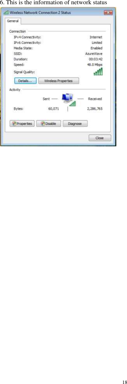
![15 6. You can check the connection status by clicking [Status] in the pop-up dialogue 7. Here is the wireless network connection status ii. For Windows Vista OS Following are the instructions to setup wireless connection for Windows Vista. 1. Right-click on the network icon located on desktop shortcut. When you see the dialogue, please click [Connect to a network]](https://usermanual.wiki/AzureWave-Technologies/NU153H/User-Guide-1381246-Page-15.png)
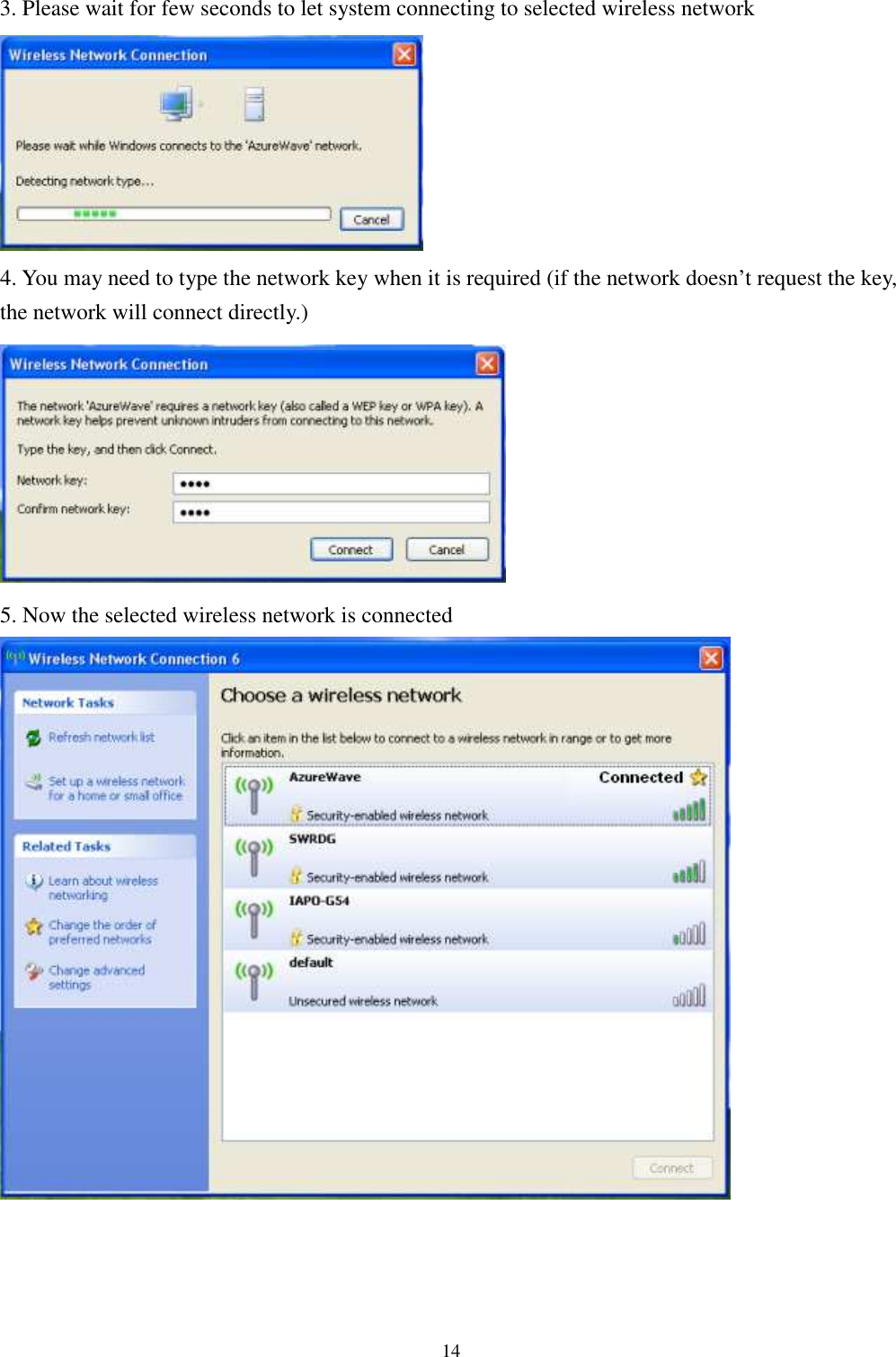
![162. Choose wireless network within your range and click [Connect] * If selected network is not secure, please choose [Connect anyway] 3. You may need to wait for few seconds when Windows connects to wireless network](https://usermanual.wiki/AzureWave-Technologies/NU153H/User-Guide-1381246-Page-16.png)
![174. Now the selected wireless network is connected 5. If you want to see the connection status, please right-click on the network you choose and select [Status]](https://usermanual.wiki/AzureWave-Technologies/NU153H/User-Guide-1381246-Page-17.png)
![19IV. Setup for Ad-hoc Mode i. For Windows XP OS If you want to choose Ad-hoc mode, please right-click network icon on desktop shortcut and choose “Open Network Connections”, or go to [Control Panel] and double-click “Network Connection” icon. When you see the “Network Connections” screen, please follow the steps below to setup Ad-hoc mode.](https://usermanual.wiki/AzureWave-Technologies/NU153H/User-Guide-1381246-Page-19.png)
![213. Choose “Use the following IP address:” and type the IP address; then click [OK] *Note: the IP address of the other wireless card should be set with the same subnet mask 4. Right-click the “Wireless Network Connection” icon and choose “properties”](https://usermanual.wiki/AzureWave-Technologies/NU153H/User-Guide-1381246-Page-21.png)
![22 5. Select “Wireless Network” tab and choose [Add] 6. Type “Network name (SSID)” and choose “Data encryption” if you want to protect the network security 7. When you see the dialogue showing your network is unsecured, please click [Continue Anyway]](https://usermanual.wiki/AzureWave-Technologies/NU153H/User-Guide-1381246-Page-22.png)
![253. Right-click the connected network icon and choose “Properties” 4. When you see the warning message, please click [Continue]](https://usermanual.wiki/AzureWave-Technologies/NU153H/User-Guide-1381246-Page-25.png)
![265. Choose “Networking” tab and double-click the “Internet Protocol Version 4 (TCP/IPv4)” item 6. Choose “Use the following IP address:” and type the IP address; then click [OK] *Note: the IP address of the other wireless card should be set with the same subnet mask](https://usermanual.wiki/AzureWave-Technologies/NU153H/User-Guide-1381246-Page-26.png)
![27 7. Choose “Manage wireless networks” bar 8. Select [Add]](https://usermanual.wiki/AzureWave-Technologies/NU153H/User-Guide-1381246-Page-27.png)
![289. Choose “Create ad-hoc network” 10. Please click [Next]](https://usermanual.wiki/AzureWave-Technologies/NU153H/User-Guide-1381246-Page-28.png)
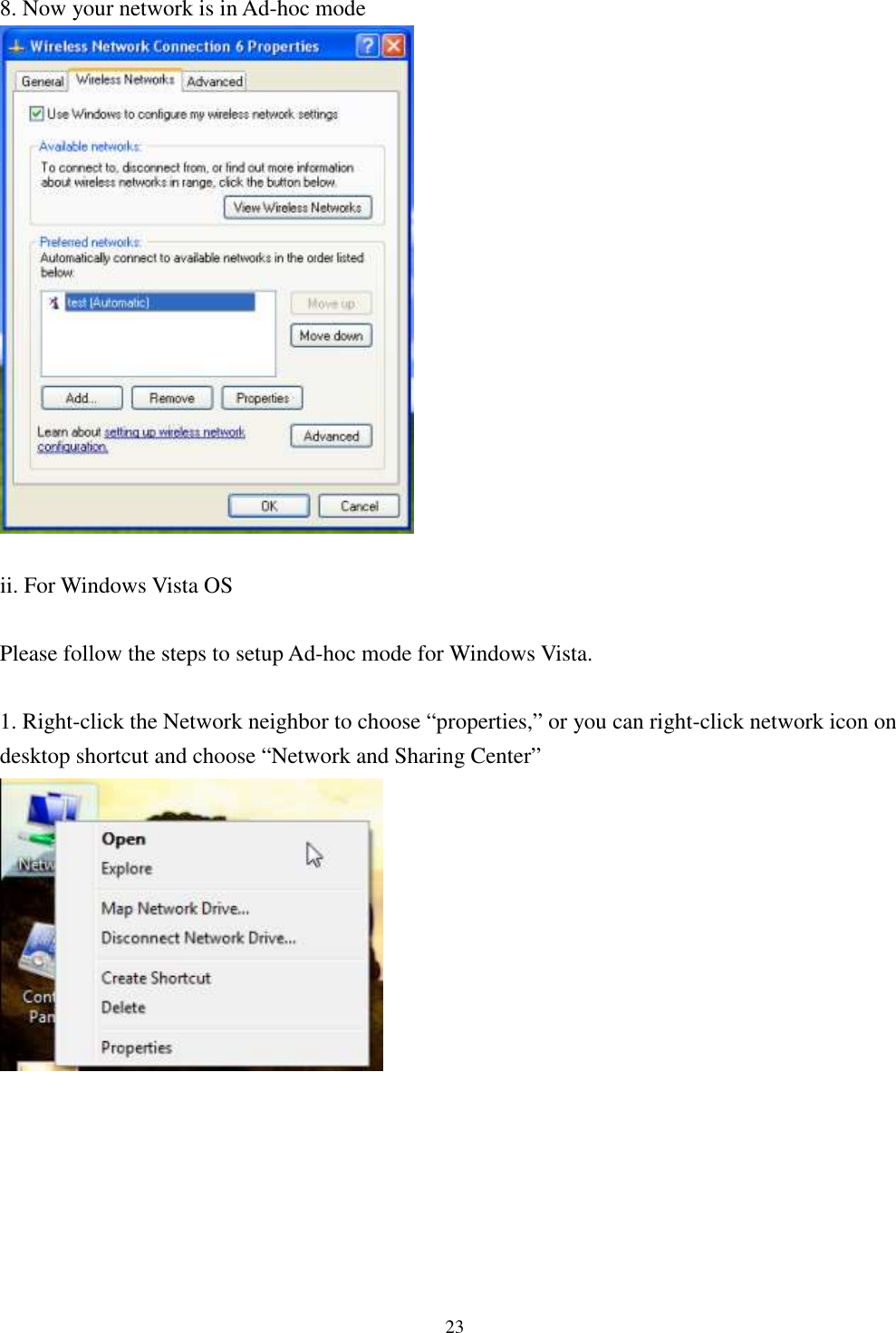
![2911. Enter “Network name” and if you want to protect the network security, please choose in “security type”; then click [Next] 12. Now your network is in Ad-hoc mode](https://usermanual.wiki/AzureWave-Technologies/NU153H/User-Guide-1381246-Page-29.png)