BAE Systems WINTLAW 802.16 Wideband Transceiver User Manual XX XXXX Exhibit Cover
BAE Systems 802.16 Wideband Transceiver XX XXXX Exhibit Cover
Contents
- 1. Manual 1 of 2
- 2. Manual 2 of 2
Manual 1 of 2

5015 B.U. Bowman Drive Buford, GA 30518 USA Voice: 770-831-8048 Fax: 770-831-8598
Certification Exhibit
FCC ID: Y75WINTLAW
FCC Rule Part: 15.247
ACS Report Number: 10-0313.W03.11.A
Manufacturer: BAE Systems
Model: R3T-S-700
Manual

Date: Jan 19, 2011
Revision: I
CAGE Code: 0D0D0
BAE Systems Information and Electronic Systems Integration Inc.
Network Systems
164 Totowa Road, Wayne, NJ 07474-0975 USA
Telephone (973) 633-6000
R3T-S-700 Users Guide
Jan 19, 2011
Prepared For: General Distribution
BAE Systems Information and Electronic Systems Integration Inc. – Network Systems (NS) Proprietary
This data, furnished to US Government representatives, shall not be disclosed outside the customer and
shall not be duplicated, used, or disclosed in whole or in part for any purpose other than to evaluate the
information provided, that if a contract is awarded to this offeror as a result of or in connection with the
submission of this data, the customer shall have the right to duplicate, use or disclose the data to the
extent provided in the contract. This restriction does not limit the customer's right to use information
contained in the data if it is obtained from another source without restriction. The data subject to this
restriction is contained in sheets marked with the restriction legend.
WARNING: This document contains technical data whose export is restricted by the Arms Export Control
Act (Title 22, U.S.C., Sec 2751, et seq.) or the Export Administration Act of 1979, as amended, Title 50,
U.S.C., app. 2401 et seq. Violations of these export laws are subject to severe criminal penalties. This
information in document and electronic form, including any attachments and exhibits hereto, may not be
exported, released or disclosed to foreign persons inside or outside the United States without first
obtaining the proper export authority. Recipient shall include this notice with any reproduced portion of
this document.
DUNS 19-495-6751
Total number of pages: 87

Date: Jan 19, 2011
Revision: I
CAGE Code: 0D0D0
BAE Systems Information and Electronic Systems Integration Inc.
Network Systems
164 Totowa Road, Wayne, NJ 07474-0975 USA
Telephone (973) 633-6000
FCC General Statements and Warnings:
Warning: Changes or modifications to this device not expressly approved by BAE Systems could void
the user’s authority to operate the equipment.
NOTE: This equipment has been tested and found to comply with the limits for a Class B digital device,
pursuant to Part 15 of the FCC Rules. These limits are designed to provide reasonable protection against
harmful interference in a residential installation. This equipment generates, uses, and can radiate radio
frequency energy and, if not installed and used in accordance with the instructions, may cause harmful
interference to radio communications. However, there is no guarantee that interference will not occur in a
particular installation. If this equipment does cause harmful interference to radio or television reception,
which can be determined by turning the equipment off and on, the user is encouraged to try to correct the
interference by one or more of the following measures:
• Reorient or relocate the receiving antenna.
• Increase the separation between the equipment and receiver.
• Connect the equipment into an outlet on a circuit different from that to which the receiver is connected.
• Consult the dealer or an experienced radio/TV technician for help.
NOTE: This equipment complies with FCC radiation exposure limits set forth for an uncontrolled
environment. This equipment should be installed and operated with minimum distance 20cm between the
radiator and your body. This transmitter must not be co-located or operating in conjunction with any other
antenna or transmitter.”

Date: Jan 19, 2011
Revision: I
CAGE Code: 0D0D0
BAE Systems Information and Electronic Systems Integration Inc.
Network Systems
164 Totowa Road, Wayne, NJ 07474-0975 USA
Telephone (973) 633-6000
Table Of Contents
1.0 802.16 SYSTEM OVERVIEW AND INTERCONNECTS ................................................1
2.0 1U RADIO ............................................................................................................................5
2.1 1UR Features .....................................................................................................5
2.2 UR Installation and Startup Procedures.............................................................5
Cable Connection.........................................................................................5
Startup – BS, SS, Bridging, Non-Bridging ..................................................7
3.0 1UR Physical I/O ..................................................................................................................9
4.0 SYSTEM CONFIGURATION ...........................................................................................14
Base-Station Login Page........................................................................................14
Base-Station Home Page........................................................................................15
Base-Station Software Configuration Page ...........................................................17
Base Station Radio Control Page...........................................................................22
Base Station Service Flows....................................................................................25
Base Station Registered SS Page ...........................................................................27
Base Station ACM Parameters Page......................................................................29
Base Station Status Page........................................................................................31
Base Station Bit Status...........................................................................................32
Base Station Maintenance Page .............................................................................34
Base Station Network Status Page.........................................................................36
Base Station Power Settings Page..........................................................................37
Base Station Test Page...........................................................................................39
Base Station Admin Page.......................................................................................40
Base Station Software Update Page.......................................................................41
Base Station Version Page .....................................................................................42
Base Station Contact Page .....................................................................................44
Subscriber Station Login Page...............................................................................44
Subscriber Station Home Page...............................................................................45
Subscriber Station Software Configuration Page ..................................................46
Subscriber Station Radio Control Page..................................................................48
Subscriber Station Service Flow Page ...................................................................51
Subscriber Station Status Page...............................................................................53
Subscriber Station Bit Status Page.........................................................................54
Subscriber Station Maintenance Page....................................................................56
Subscriber Station Network Status Page................................................................58
Subscriber Station Power Settings Page ................................................................59
Subscriber Station Test Page .................................................................................61
Subscriber Admin Page..........................................................................................62
Subscriber Software Update Page..........................................................................63
Subscriber Station Version Page............................................................................64
Contact Page ..........................................................................................................65
5.0 SYSTEM SETUP AND CONFIGURATION EXAMPLE ................................................66
5.1 Bridging Mode Scenario ..................................................................................66

Date: Jan 19, 2011
Revision: I
CAGE Code: 0D0D0
BAE Systems Information and Electronic Systems Integration Inc.
Network Systems
164 Totowa Road, Wayne, NJ 07474-0975 USA
Telephone (973) 633-6000
5.2 Bridging Base Station Configuration Mode ....................................................66
5.3 Bridging Subscriber Station Configuration Mode ...........................................69
5.3.1 Bridging Base Station Configuration Mode with two subscribers ...............70
5.4 Non-Bridging Mode Scenario..........................................................................72
5.5 Non-Bridging Base Station Configuration Mode ............................................73
5.6 Non-Bridging Subscriber Station Configuration Mode...................................75
5.6.1 Non-Bridging Base Station Configuration Mode with Two
subscribers..................................................................................................76
6.0 PERFORMANCE ...............................................................................................................79
Radio Performance.................................................................................................79
6.1 Receiver Sensitivity .........................................................................................79
6.2 User Data Rates................................................................................................80
APPENDIX: DEFINITIONS, ACRONYMS, AND ABBREVIATIONS ......................82
Revision: I
CAGE Code: 0D0D0
ITAR CONTROLLED
1
BAE SYSTEMS PROPRIETARY INFORMATION
Use or disclosure of data contained on this sheet
is subject to the restriction on the title page.
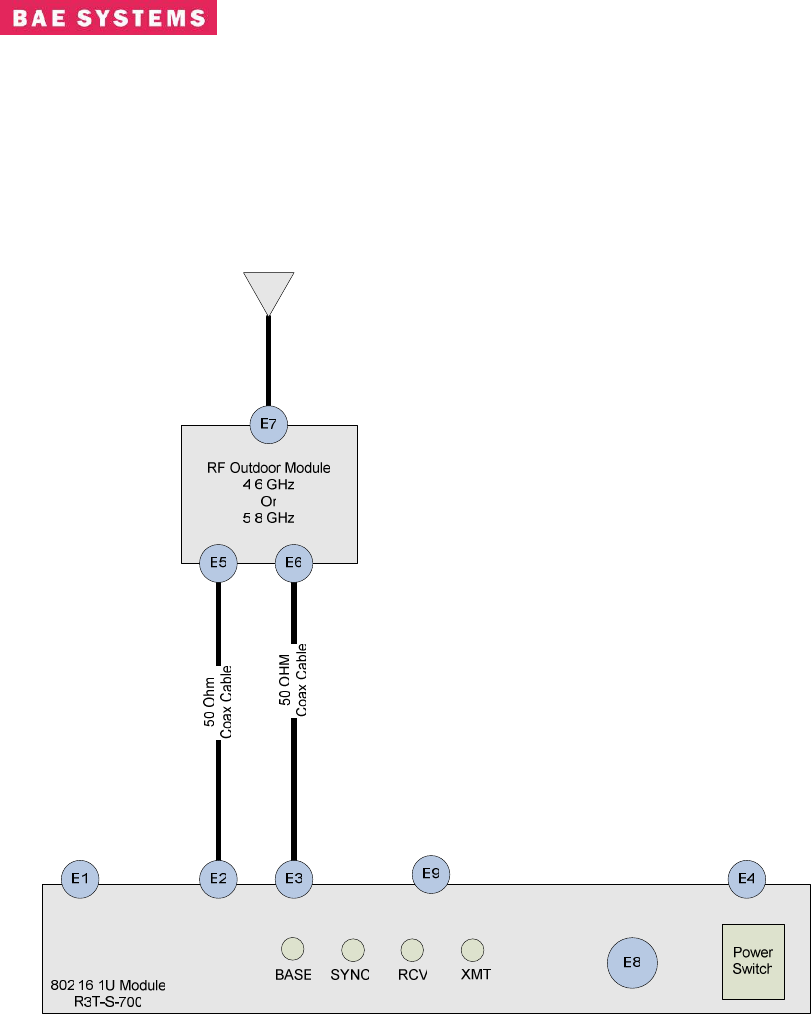
1.0 802.16 SYSTEM OVERVIEW AND INTERCONNECTS
The functional block diagram of the 802.16 System is shown in Figure 1. The R3T-S-700 radio
system is comprised of the R3T-S-700 Indoor radio and the Outdoor RF Unit. Table 1 provides a
definition of the system interfaces. The RF Outdoor unit can be located up to 100 feet from the
indoor unit. The system is designed to operate with up to 10 db cable loss between the Indoor
and Outdoor units.
Figure 1 : 802.16 System Block Diagram

Revision: I
CAGE Code: 0D0D0
ITAR CONTROLLED
2
BAE SYSTEMS PROPRIETARY INFORMATION
Use or disclosure of data contained on this sheet
is subject to the restriction on the title page.
No. Interface Connector Direction Description
E1 Ethernet
Control/Data
RJ-45 Input/Output 10/100BaseT Ethernet Network Connector
E2 RF -Radio RX TNC
Female
Input/Output
Input: RF Rx IF Input 5.8 or 4.6 GHz
Output: 15VDC prime power for RF Unit
E3 RF -Radio Tx TNC
Female
Output RF Tx IF Output 5.8 or 4.6 GHz. TTL Signal For RF Unit T/R
Control: HIGH, 2.4V MIN TO 5V MAX; LOW, 0.7 VOLTS
MAX TO 0 V MIN.
E4 Power AC Plug Input 110 VAC Power Source –Less than 1 Amp
E5 RF - RF Unit J2 Type N
Female
Input/Output Output: RF Unit Rx out Port
Input: Primary 15VDC
E6 RF –RF Unit J1 Type
TNC
Female
Input RF Module Tx in Port. TTL Signal : HIGH, 2.4V MIN TO 5V
MAX; LOW, 0.7 VOLTS MAX TO 0 V MIN.
E7 RF –RF Unit J3 Type N
Female
Input/Output Antenna Port (Tx/Rx)
Omni or Directional Antenna
E8 Serial Control
Interface
DB9 Input/Output RS-232 Serial Connection – User Port SW Maintenance
E9 Serial Control
Interface
DB25 Input/Output RS-422/232 Serial Connection supporting GPS 1PPS, T/R
Switch
Table 1 – R3T-S-700 Interfaces
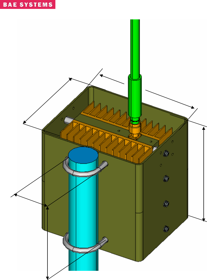
Table 1 describes the interface of the R3T-S-700 System. Connections between the Indoor and
Outdoor units should be made using low loss 50 ohm coaxial cable. The RF unit includes a solar
shield and can be mounted to a mast as shown in Figure 2 below. Most omni-directional antenna
designs can be mounted directly to the RF Unit Antenna Port N-Type connector (J3)
Revision: I
CAGE Code: 0D0D0
ITAR CONTROLLED
3
BAE SYSTEMS PROPRIETARY INFORMATION
Use or disclosure of data contained on this sheet
is subject to the restriction on the title page.
Figure 2 – Typical RF Outdoor Unit Mount to Mast
7.75”
7.75”
6.42”
6.1”
2.375”
Revision: I
CAGE Code: 0D0D0
ITAR CONTROLLED
4
BAE SYSTEMS PROPRIETARY INFORMATION
Use or disclosure of data contained on this sheet
is subject to the restriction on the title page.
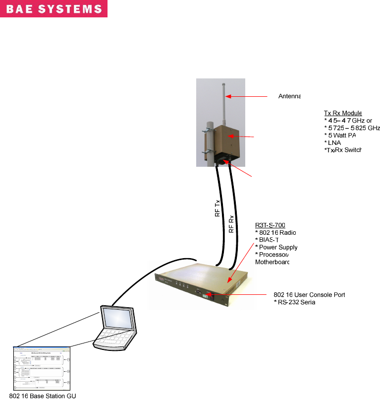
Figure 3 shows a typical radio setup using an omni antenna
Figure 3 – Typical R3T-S-700 Configuration
Revision: I
CAGE Code: 0D0D0
ITAR CONTROLLED
5
BAE SYSTEMS PROPRIETARY INFORMATION
Use or disclosure of data contained on this sheet
is subject to the restriction on the title page.
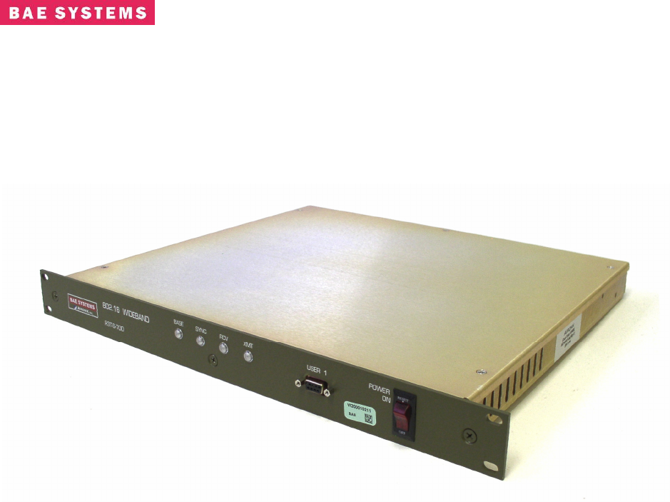
2.0 1U RADIO
This unit is a COTS 1U Radio (1UR) that contains 802.16+ functionality. This unit mates with
BAE supplied RF Unit and antenna system. With the appropriate external powerhead and
antenna systems, it operates at both 5.8 GHz and 4.6 GHz ranges.
Figure 4. COTS 802.16 1U Radio (1UR)
2.1 1UR Features
All the features and advantages of an IEEE 802.16 platform.
Simple yet powerful GUI for radio configuration.
Additional features from Aeronix 802.16+ MAC and PHY.
o Designed for 2000 mph Doppler
o Designed for 70 Mile Range, 72 Mbps Burst Rate (QAM64)
o TRANSEC (v2.0 and above)
o Designed for vibration tolerance
o Extra Modulation/Encoding options for rotor aircraft
o Dual Frequency (supports 5.8 GHz and 4.6 GHz).
o IPV6 Capable
o Linux Based MAC
o Software Defined Radio
o Evolution Path to 802.16e
2.2 UR Installation and Startup Procedures
Cable Connection
With unit power OFF, connect the cables as described and shown below:
Revision: I
CAGE Code: 0D0D0
ITAR CONTROLLED
6
BAE SYSTEMS PROPRIETARY INFORMATION
Use or disclosure of data contained on this sheet
is subject to the restriction on the title page.
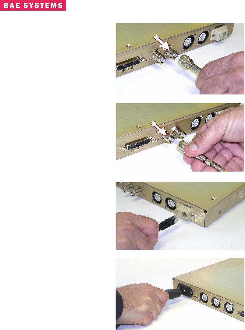
1) Connect the RF Receive
Cable to the 1U radio rear
panel RX port, as shown
in Figure 5.
WARNING!
Unit power must be OFF.
Figure 5. 1UR Receive Connection
2) Connect the RF Transmit
Cable to the 1U radio rear
panel TX port, as shown
in Figure 6.
WARNING!
Unit power must be OFF.
Figure 6. 1UR Transmit Connection
3) Plug in the RJ-45 Network
Connector into the RJ-45
ETHERNET receptacle on
the 1U chassis rear panel,
as shown in Figure 7.
Figure 7. 1UR AX100617-00x Network Connection
4) Plug supplied Power Cable
female end into 1U chassis
rear panel POWER
receptacle as shown in
Figure 8.
5) Plug supplied Power
Cable male end into
correct power source.
6) Power-on the unit by
pressing the power switch
on the 1U chassis front
panel.
Figure 8. 1UR Power Connection
Revision: I
CAGE Code: 0D0D0
ITAR CONTROLLED
7
BAE SYSTEMS PROPRIETARY INFORMATION
Use or disclosure of data contained on this sheet
is subject to the restriction on the title page.
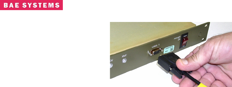
7) Connect to the
appropriate 9-pin Cable
to the 1U chassis front
panel USER 1 port, as
shown in Figure 9.
Figure 9. 1UR User Port Connection
Startup – BS, SS, Bridging, Non-Bridging
Enter the following commands from a terminal connected to the user1 port. The terminal should
be connected serially at Baud Rate = 115200, 8-N-1, and no flow control.
There are four base startups which are Base-station or Subscriber-station running in either
bridging mode or non-bridging mode. To start in the modes perform the following:
1) >cd /mnt/jffs2
2) To run the system as a Base station in bridging mode: >cp startShimBridgeBS start
3) To run the system as a Base station in non-bridging mode: >cp startShimBS start
4) To run the system as a Subscriber station in bridging mode: >cp startShimBridgeSS start
5) To run the system as a Subscriber station in non-bridging mode: >cp startShimSS start
Once you have copied the appropriate script to the ‘start’ script perform one of the following
modifications.
Startup Bridging Mode
Enter the following commands from any console connected to the 802.16 radio.
1) >cd /mnt/jffs2
2) Vi the start* file. The following (or similar) results will be displayed on the console.
-
-
-
./mnt/jffs2/brctl addbr mybridge
./mnt/jffs2/brctl addif mybridge eth0
./mnt/jffs2/brctl addif mybridge aend0
#This is where you need to set the network address so that you can run
the GUI
ifconfig mybridge 192.168.100.1 netmask 255.255.255.0
cd /mnt/jffs2
-
-
-
3) Modify the “ifconfig” line to have the desired IP address.
4) Reboot at the console prompt: >reboot

Revision: I
CAGE Code: 0D0D0
ITAR CONTROLLED
8
BAE SYSTEMS PROPRIETARY INFORMATION
Use or disclosure of data contained on this sheet
is subject to the restriction on the title page.
Startup IP Mode
Enter the following commands from any console connected to the 802.16 radio.
1) >cd /mnt/jffs2
2) Vi the start* file. The following (or similar) results will be displayed on the console.
-
insmod macss.ko subscriberNumber=1
-
ifconfig eth0 192.168.100.1
-
route add -net 192.168.1.0 netmask 255.255.255.0 gw 10.1.1.1 dev aend0
-
3) Modify the “ifconfig eth0” line to have the desired IP address.
4) If this is for a subscriber change this line ‘insmod macss.ko subscriberNumber=1’ to =
the desired subscriber number.
5) Modify the “route add” line to have the appropriate -net address. If you’re on the base
add the subscribers, if you’re on the subscriber add the base-stations.
6) Reboot at the console prompt: >reboot
Revision: I
CAGE Code: 0D0D0
ITAR CONTROLLED
9
BAE SYSTEMS PROPRIETARY INFORMATION
Use or disclosure of data contained on this sheet
is subject to the restriction on the title page.
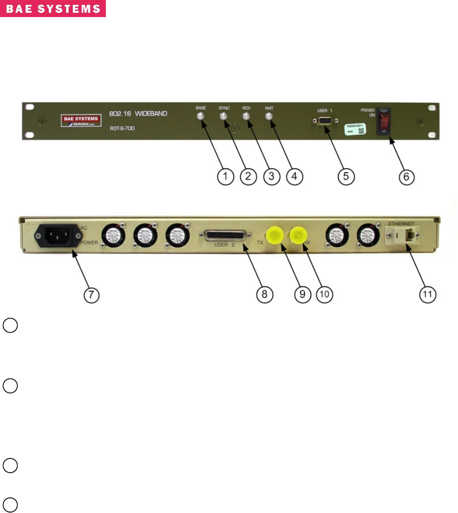
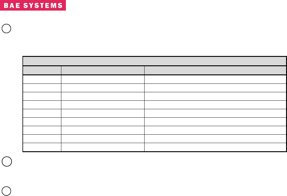
3.0 1UR Physical I/O
The front panel of a COTS 1U 802.16+ radio is shown in Figure 10. The rear panel is shown in
Figure 11. Indicated controls, connectors, ports, and indicators are described below.
Figure 10. COTS 1UR Physical I/O, Front Panel
Figure 11. COTS 1UR Physical I/O, Rear Panel
1
1UR LED - Base Indicator - The ‘BASE’ LED is illuminated continuously when the
radio is configured as a Base-Station. The ‘Base’ LED flashes at 1 second intervals when
the radio is configured as a Subscriber-Station. When the LED is not illuminated, the
power is off.
2
1UR LED - Synchronization Indicator – The ‘SYNC’ LED flashes on a Subscriber-
Station when it has received maps from the Base-Station (sync) and it is illuminated
continuously when the Subscriber-Station has registered with the Base-Station. The
‘SYNC’ LED is off on the Base-Station when no Subscriber-Stations are registered and is
illuminated continuously when Subscriber-Stations are registered.
3
1UR LED - Receive Indicator - The ‘RCV’ LED is illuminated when a unit is receiving
frames. It is sampled on a 1 second interval.
4
1UR LED - Transmit Indicator - The ‘XMT’ LED is illuminated when a unit is
transmitting frames. It is sampled on a 1 second interval.
Revision: I
CAGE Code: 0D0D0
ITAR CONTROLLED
10
BAE SYSTEMS PROPRIETARY INFORMATION
Use or disclosure of data contained on this sheet
is subject to the restriction on the title page.
5
1UR PORT – User 1 Port - The User 1 port is a standard 9 pin female connector that
supports RS-232 signals (Baud = 115200, 8-N-1 no flow control) with the following pin
assignments:
Table 3.0-1. 1UR User 1 Port Pinout
Pin Signal Name Signal Description
01
02 RS232_TX1A RS232 Output
03 RS232_RX1A RS232 Input
04
05 RS232_RTN2 Sig_Gnd
06
07
08
09
6
1UR SWITCH – Power On/Off Switch and Indicator -
This power switch turns the
radio On and Off. The switch is illuminated when the power is turned On and not
illuminated when the power is turned Off.
7
1UR CONNECTOR – AC Power Connector - The unit requires 120V AC @ 60Hz
power. It accepts the supplied standard IEC-430 AC power cord.
Revision: I
CAGE Code: 0D0D0
ITAR CONTROLLED
11
BAE SYSTEMS PROPRIETARY INFORMATION
Use or disclosure of data contained on this sheet
is subject to the restriction on the title page.
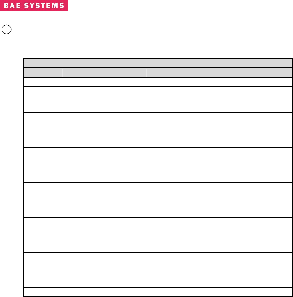
8
1UR PORT – User 2 Port - The User 2 port is a standard 25 pin female connector that
supports RS-232/RS-422 maintenance debug, transmit receive switch, 1PPS, and
reserved signals with the following pin assignments:
Table 3.0-2. 1UR User 2 Port Pinout
Pin Signal Name Signal Description
01 RS232/RS422-_TX2A RS232 / RS485 / RS422- Output
02 RS232/RS422-_RX2A RS232 / RS485 / RS422- Input
03 RS485 / RS422+_TX2B RS485 / RS422+ Output
04 RS485 / RS422+_RX2B RS485 / RS422+ Input
05
06 RS232_RTN Sig_Gnd
07
08
09
P
*
P
TR_SW1+ RS422 Output
10
P
*
P
TR_SW1- RS422 Output
11
12 RSVD (TR_SW2+) RS422 Output
13 RSVD (TR_SW2-) RS422 Output
14
15 RSVD (ZEROIZE+) No Connect
16 RSVD (ZEROIZE-) No Connect
17
18
19
20 1PPS_TTL 50 Ohm TTL Input - Daisy Chain
21 1PPS_TTL 50 Ohm TTL Input
22 1PPS_RTN Sig_Gnd
23 1PPS_RTN Sig_Gnd - Daisy Chain
24 1PPS_TERM_IN Termination Jumper
25 1PPS_TERM_OUT Termination Jumper
Revision: I
CAGE Code: 0D0D0
ITAR CONTROLLED
12
BAE SYSTEMS PROPRIETARY INFORMATION
Use or disclosure of data contained on this sheet
is subject to the restriction on the title page.
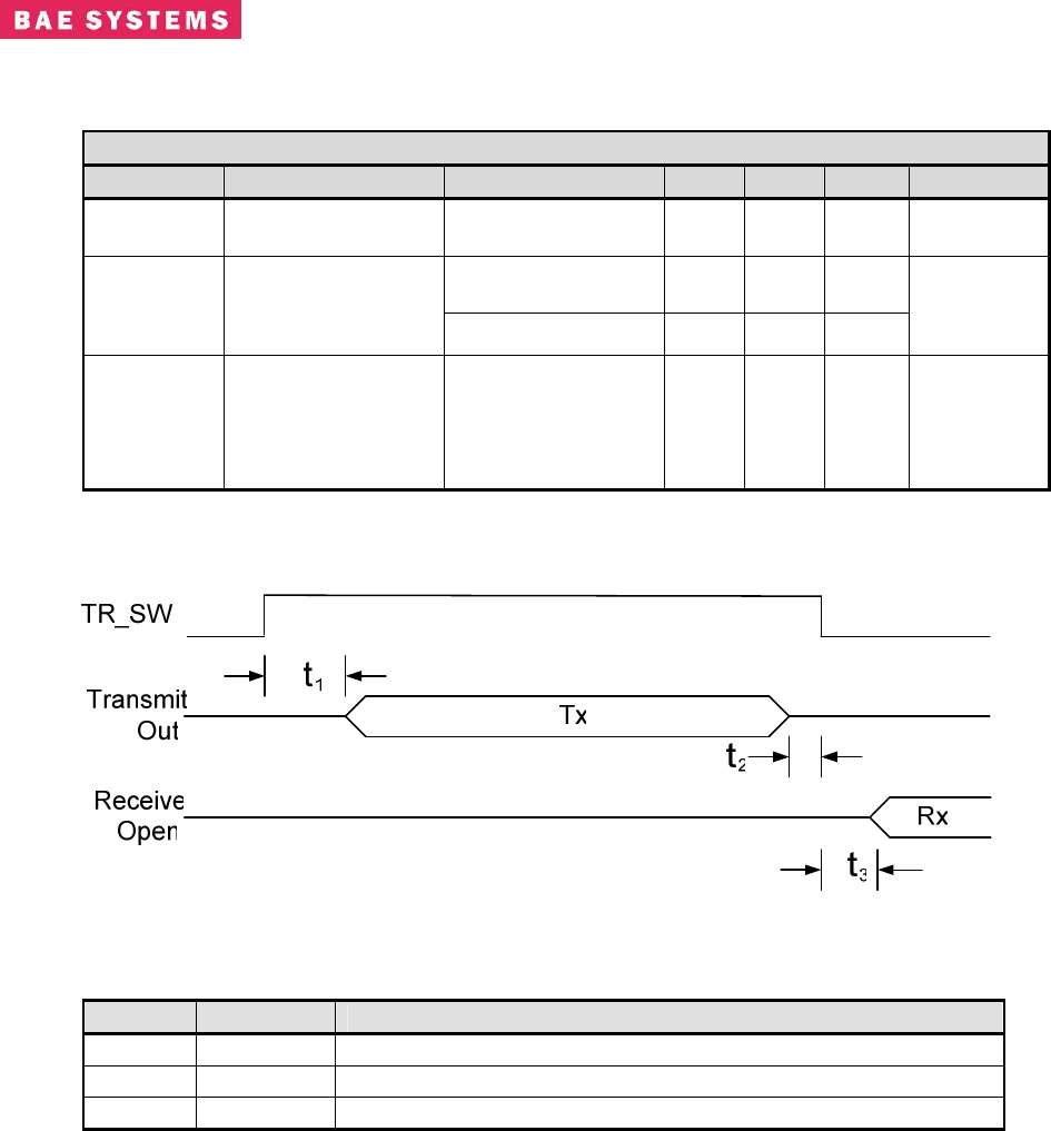
Table 3.0-3. 1UR User 2 Port TX Enable Specifications
Parameter Test Conditions Min Typ
P
1
P
Max Unit
V
B
O
B
Open-circuit output
voltage A or B, No load 0 - - +5V
B
CC
B
V
No load (open
circuit) 3.3 4.2 +5V
B
CC
B
| V
B
OD(SS)
B
|
Steady-state
differential output
voltage magnitude R
B
L
B
= 54 Ω 1.8 2.5 - -
V
∆| V
B
OD(SS)
B
|
Change in Steady-
state differential
output voltage
between logic
states
- - -0.1 - - 0.1 V
P
1
P
All typical values are at V
B
CC
B
= 5V and 25°C
Figure 12. TR_SW Timing
Marker Time (us) Description
t1 1.5 us Time from Tx Enable Active to start of Tx
t2 0.5 us Time from Transmit Out Complete to Tx Enable Inactive
t3 1.5 us Time from Tx Enable Inactive to start of Rx Window
Revision: I
CAGE Code: 0D0D0
ITAR CONTROLLED
13
BAE SYSTEMS PROPRIETARY INFORMATION
Use or disclosure of data contained on this sheet
is subject to the restriction on the title page.
9
1UR CONNECTOR – Tx RF / Tx Enable Connector - This female TNC connector is
connected to the 802.16 RF Transmit system. +5 DC Power is present on center pin.
10
1UR CONNECTOR - Rx RF Connector- This female TNC connector is connected to
the 802.16 RF Receive system. +15V, 4 Amps is present on center pin.
11
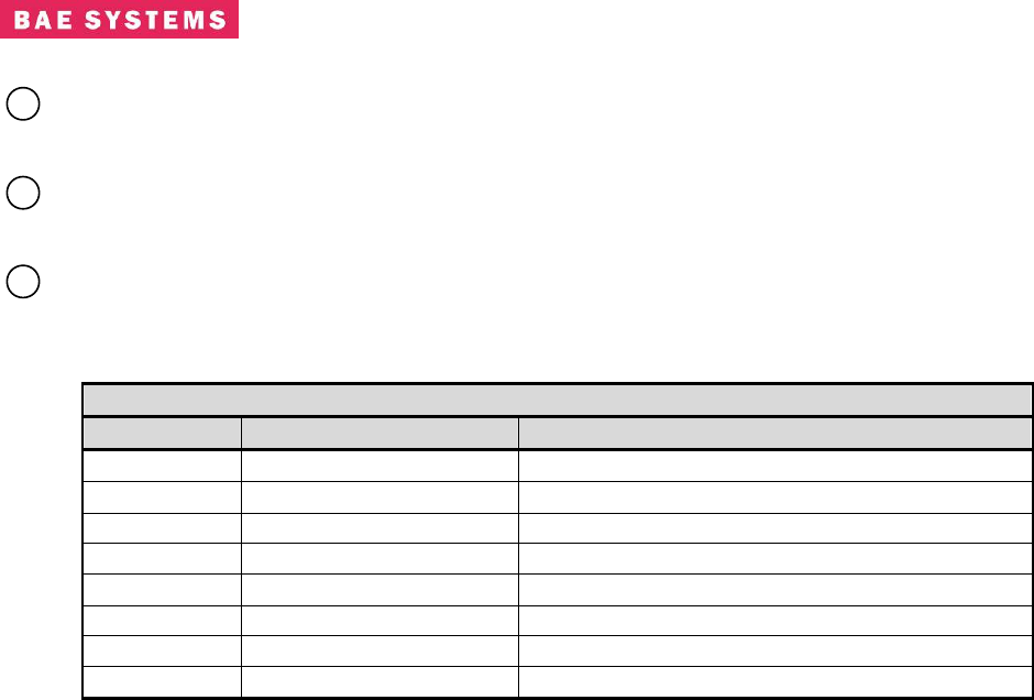
1UR CONNECTOR - Ethernet Connector - The Ethernet connector is a standard
10/100/1000BaseT RJ45 receptacle. It has the following pin assignments which conform
to the Ethernet specification:
Table 3.0-4. 1UR Ethernet RJ45 Connector Pinout
Pin Signal Name Signal Description
01 ETH_CHA+ 10/100/1000BaseT
02 ETH_CHA- 10/100/1000BaseT
03 ETH_CHB+ 10/100/1000BaseT
04 ETH_CHC+ 10/100/1000BaseT
05 ETH_CHC- 10/100/1000BaseT
06 ETH_CHB- 10/100/1000BaseT
07 ETH_CHD+ 10/100/1000BaseT
08 ETH_CHD- 10/100/1000BaseT
Revision: I
CAGE Code: 0D0D0
ITAR CONTROLLED
14
BAE SYSTEMS PROPRIETARY INFORMATION
Use or disclosure of data contained on this sheet
is subject to the restriction on the title page.
4.0 SYSTEM CONFIGURATION
This simple yet powerful GUI uses uncomplicated intuitive screens to allow the average 802.16
user:
Configure the system for their network
Take the system operational
Perform maintenance
The GUI screens and all their respective elements are described in the following subsections.
To get to the main page, types the following URL: http://<ip address of the radio>/
A step-by-step setup example for bridging mode and non-bridge mode are provided in section 5
of this document. The bridging is the preferred method due to enhanced capabilities such as
multicast and it does not require manual route configuration.
The recommended browsers to use are Internet Explorer Version 7 and Mozilla Firefox.
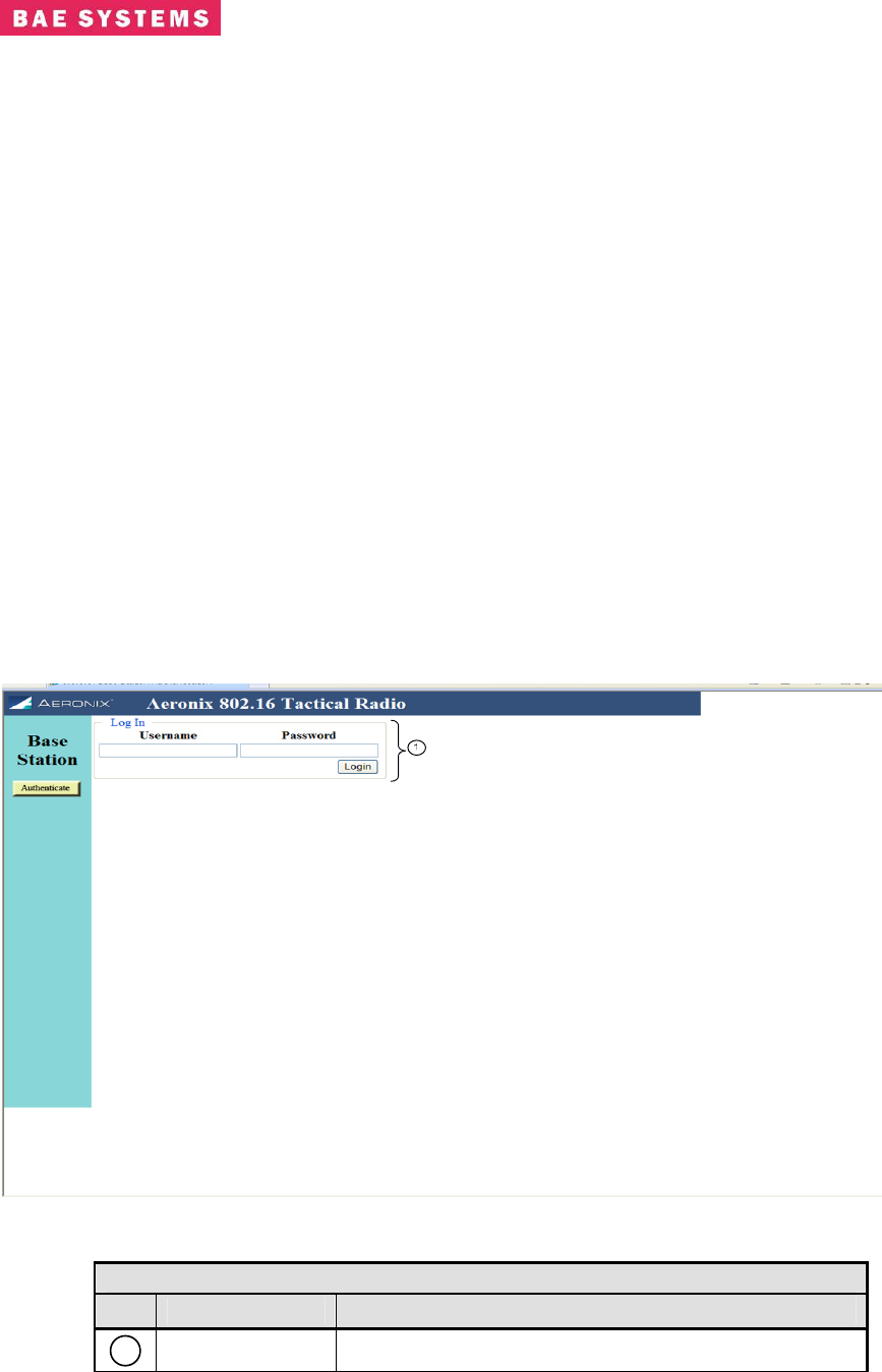
Base-Station Login Page
The base station requires a login for access to configuration screens. The base station contains
one crypto officer login and one user login. Access to certain configuration items is restricted
for the user login.
Table 0-1. Base Station Login Page
Link Description
1
Login Location to provide the username and password
Revision: I
CAGE Code: 0D0D0
ITAR CONTROLLED
15
BAE SYSTEMS PROPRIETARY INFORMATION
Use or disclosure of data contained on this sheet
is subject to the restriction on the title page.
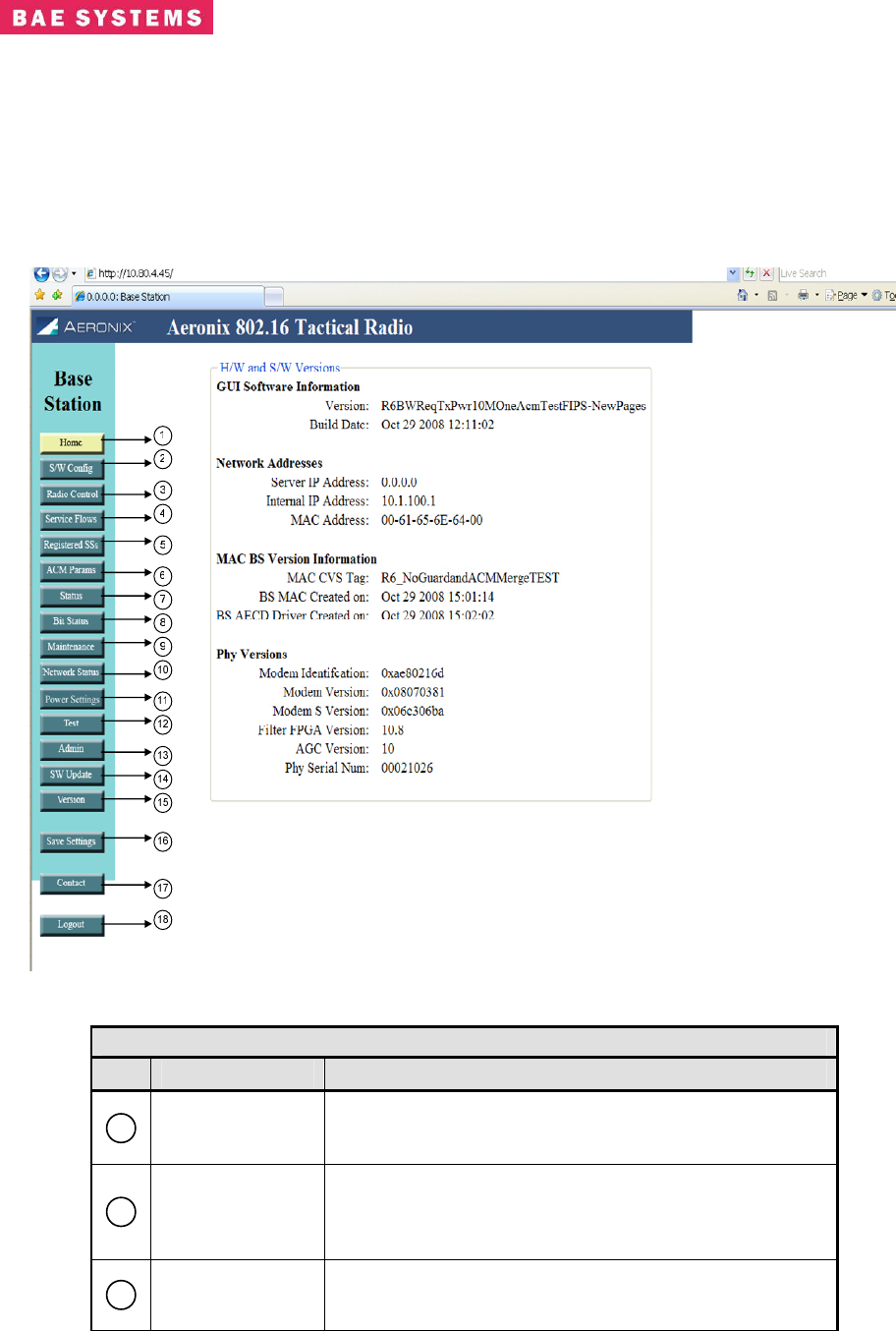
Base-Station Home Page
The base station home page contains hardware and software version information. It also
contains network address information.
Table 0-2. Base Station Home Page
Link Description
1
Home
HTML Link to the Home page that displays network
access information as well as the hardware and
software version information.
2
SW Config
HTML Link to the software configuration page; the
configuration page contains the needed tools to define
and configure the external systems interaction with the
802.16 radio.
3
Radio Control
HTML Link to the Radio Control Page; the radio control
page contains channel, initial ranging and TRANSEC
parameters. The user has limited capabilities for
Revision: I
CAGE Code: 0D0D0
ITAR CONTROLLED
16
BAE SYSTEMS PROPRIETARY INFORMATION
Use or disclosure of data contained on this sheet
is subject to the restriction on the title page.
Table 0-2. Base Station Home Page
Link Description
TRANSEC and keying.
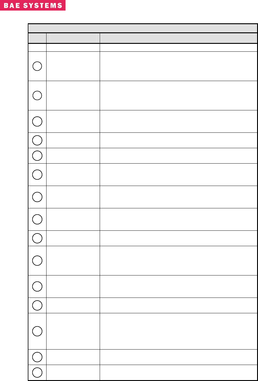
4
Service Flow
HTML Link to the Service Flow page; the service flow
page displays the current service flows within the node
and the current state of each service flow; this page is
used to enable or disable the ARQ.
5
Registered SS
HTML Link to the Registered SS page; the registered
SS page displays the current subscribers registered
within the node; this is a display page only with no
actions.
6
ACM Params
HTML Link to the parameters to adjust the automatic
changing of modulations. This screen is only accessible
to the crypto officer.
7
Status HTML Link to the Status page; the status page contains
operating status of the radio.
8
Bit Status HTML Link to the Bit Status results page. This page
provides results of the test executed at startup.
9
Maintenance
HTML Link to the Maintenance; the maintenance page
contains information for debugging and antenna
pointing.
10
Network Status
HTML Link to the Network Status page; this page
provides transmit and receive status for the Ethernet
interface.
11
Power Settings
HTML link to the Power Settings page; this page
provides the capability to enter gain settings and cable
loss settings for ranging purposes.
12
Test HTML Link to the Test page for running either a CW test
or BER test.
13
Admin
HTML Link to the administration page. This page
provides TRANSEC key selection and password
changing capabilities. The user login does not have
access to the TRANSEC key selection functions.
14
Software Update
HTML Link to the software update page. This page
provides the capability to update the software to the
crypto officer only.
15
Version HTML Link to Version page; the version page contains
the hardware and software version information.
16
Save Settings
Save Settings control key will save the current selected
values in each GUI screen to the Base Station
database. Additions, modifications or deletions are
not permanently saved to the database unless this
control key is selected.
17
Contact HTML Link to the Contact Page; the contact page
contains Aeronix Inc. contact information.
18
Logout The logout control key logs the current user out of the
system.
Revision: I
CAGE Code: 0D0D0
ITAR CONTROLLED
17
BAE SYSTEMS PROPRIETARY INFORMATION
Use or disclosure of data contained on this sheet
is subject to the restriction on the title page.
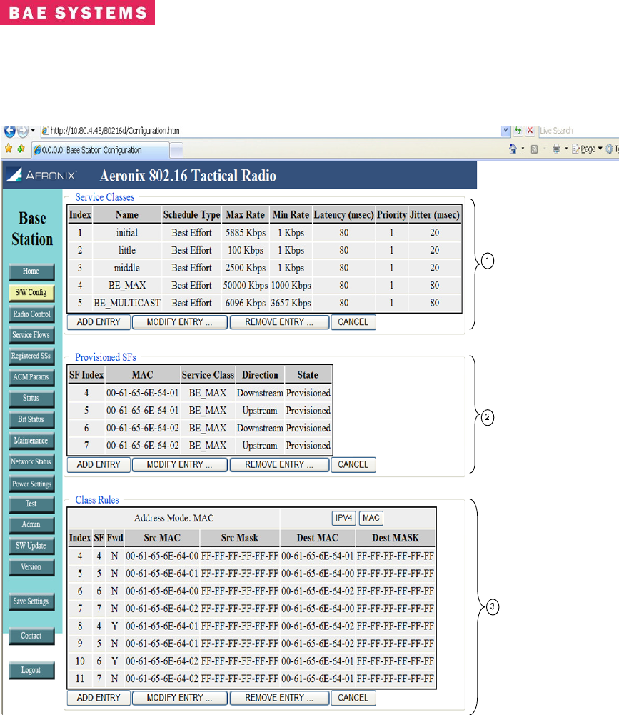
Base-Station Software Configuration Page
Non-Bridging Example
Revision: I
CAGE Code: 0D0D0
ITAR CONTROLLED
18
BAE SYSTEMS PROPRIETARY INFORMATION
Use or disclosure of data contained on this sheet
is subject to the restriction on the title page.
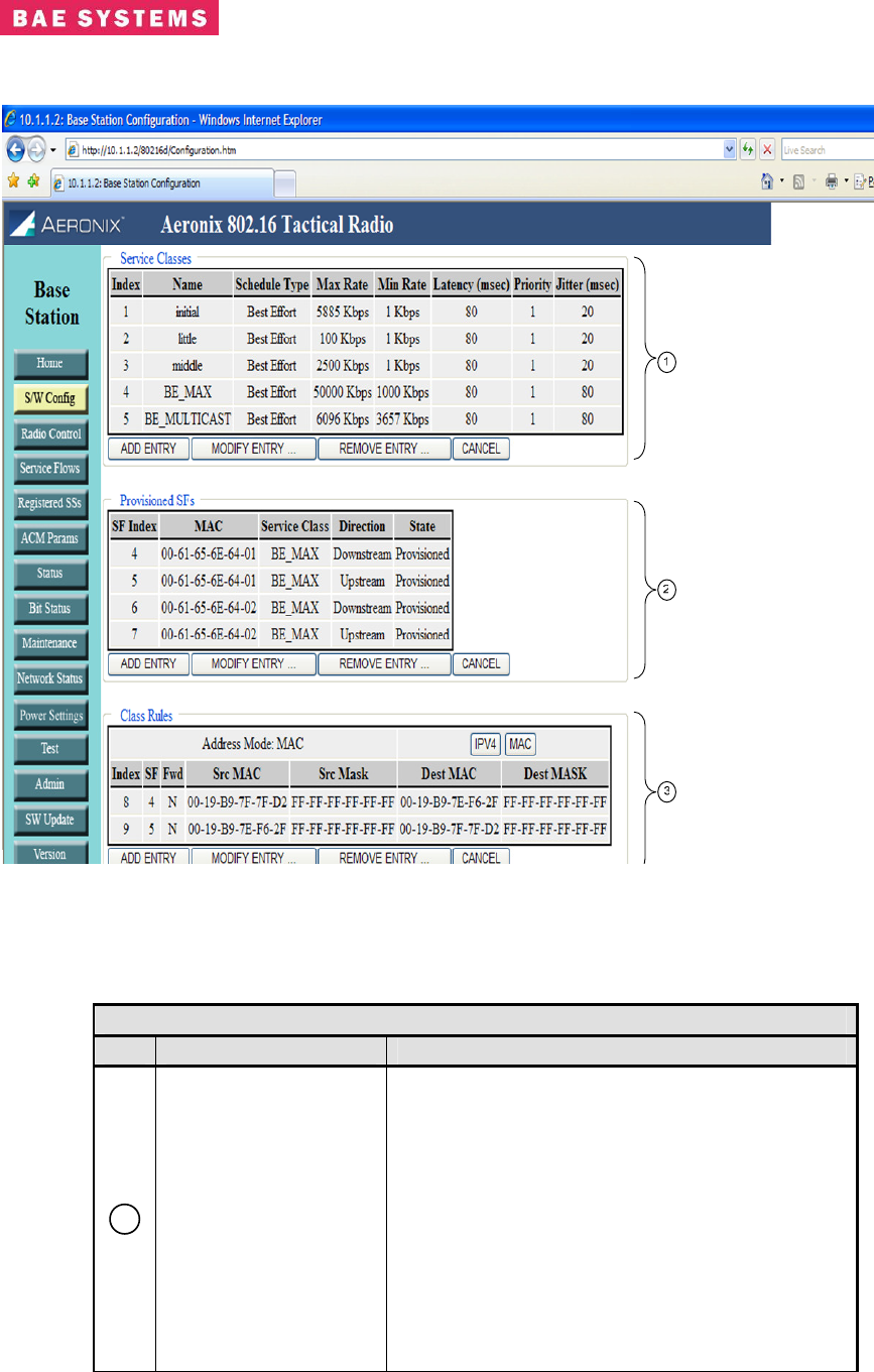
Bridging Example
Table 0-3. Base Station Software Configuration Page
Field/Control Description
1
Service Classes
Displays the service classes currently entered
which define the scheduling services for the
network.
• Add Entry Button allows for adding a new
service class entry. Click on the button
and enter the fields. When the fields are
complete click on the add button to the
right of the entry fields.
• Modify Entry Button allows for modifying a
service class entry in the table. Click on
the button and then select the entry to
modify by clicking on the modify button to
the right of the entry line. When

Revision: I
CAGE Code: 0D0D0
ITAR CONTROLLED
19
BAE SYSTEMS PROPRIETARY INFORMATION
Use or disclosure of data contained on this sheet
is subject to the restriction on the title page.
Table 0-3. Base Station Software Configuration Page
Field/Control Description
modifications are complete click the save
button to the right of the entry line.
• Remove Entry Button allows for removing
a service class entry from the table. Click
on the button and then click on the
remove button to the right of the entry line
to remove.
• Cancel Button allows for canceling the
current add or modify request.
Entry fields:
• Index – the index into the service class
table for the entry. This field is not
entered by the user.
• Name – the user defined name for the
service class.
• Schedule Type – the scheduling type for
the service class. The entries are defined
in a drop down by the system.
• Max Rate – the maximum data rate for
the service class in Kbps.
• Min Rate – the minimum data rate for the
service class in Kbps.
• Latency – the latency of the service class.
This is only used as a guideline for
pertinent schedule types.
• Priority - the priority of the service class.
This is only used for the real time and
non-real time scheduling types. Seven is
the highest priority.
• Jitter – the jitter of the service class. This
is only used as a guideline for pertinent
schedule types.
2
Provisioned Service
Flows
Displays the provisioned service flows currently
entered for the network. The service flows define
the service class for the uplink and downlink of
each subscriber station in the network.
• Add Entry Button allows for adding a new
provisioned service flow entry. Click on
the button and enter the fields. When the
fields are complete click on the add
button to the right of the entry fields.
• Modify Entry Button allows for modifying a
provisioned service flow entry in the table.
Click on the button and then select the
entry to modify by clicking on the modify
button to the right of the entry line. When
modifications are complete click the save
button to the right of the entry line.
• Remove Entry Button allows for removing
a provisioned service flow entry from the
Revision: I
CAGE Code: 0D0D0
ITAR CONTROLLED
20
BAE SYSTEMS PROPRIETARY INFORMATION
Use or disclosure of data contained on this sheet
is subject to the restriction on the title page.
Table 0-3. Base Station Software Configuration Page
Field/Control Description
table. Click on the button and then click
on the remove button to the right of the
entry line to remove.
• Cancel Button allows for canceling the
current add or modify request.
Entry fields:
• SF Index – unique index for the service
flow. Valid entries are 3-255. The values
of 1,2,3 are reserved.
• MAC – the IEEE 802.16 MAC address of
the subscriber station.
• Service Class – a drop down selection for
the service class for the service flow.
• Direction – the direction of the service
flow. Downstream is BS to SS and
upstream is SS to BS.
• State – the state of the service flow
(display only).
3
Class Rules
Displays the classifier rules currently entered for
the network. The classifiers define the paths that
traffic is allowed to flow in the network.
• Add Entry Button allows for adding a new
class rule for the network. Click on the
button and enter the fields. When the
fields are complete click on the add
button to the right of the entry fields.
• Modify Entry Button allows for modifying a
class rule entry in the table. Click on the
button and then select the entry to modify
by clicking on the modify button to the
right of the entry line. When modifications
are complete click the save button to the
right of the entry line.
• Remove Entry Button allows for removing
a class rule entry from the table. Click on
the button and then click on the remove
button to the right of the entry line to
remove.
• Cancel Button allows for canceling the
current add or modify request.
Entry Fields:
• Index - the index into the classifier table
for the entry. This field is not entered by
the user.
• SF – the SF index that the classifier is
associated. Defines the route for data
traffic.
• Fwd – forwarding flag used to specify a
downstream forwarding classifier.
Forwarding classifiers must be consistent
Revision: I
CAGE Code: 0D0D0
ITAR CONTROLLED
21
BAE SYSTEMS PROPRIETARY INFORMATION
Use or disclosure of data contained on this sheet
is subject to the restriction on the title page.
Table 0-3. Base Station Software Configuration Page
Field/Control Description
with non-forwarding classifiers. For
example, if using IP masks with the non-
forwarders, one must also use the same
mask with the forwarders. Forwarders
define data traffic from a subscriber that
should be forwarded to another
subscriber.
• Src MAC - The source external network
nodes Ethernet MAC address. This is the
source of data packets.
• Src Mask - Mask to be applied to Source
MAC field, allows you to open up a range
of MAC addresses.
• Dest MAC – The destination external
network nodes Ethernet MAC address.
This is the destination of packets.
• Dest Mask - Mask to be applied to
• Destination MAC field, allows you to open
up a range of MAC addresses.
Multicast Note:
o A service class for multicast data is automatically configured that defines the
possible bandwidth for multicast messages. The maximum and minimum rate can
be modified according to the expected multicast traffic of your system. The
multicast service class cannot be deleted as multicast support is always on in the
bridging configuration. Multicast is not currently supported in the non-bridging
configuration.
Revision: I
CAGE Code: 0D0D0
ITAR CONTROLLED
22
BAE SYSTEMS PROPRIETARY INFORMATION
Use or disclosure of data contained on this sheet
is subject to the restriction on the title page.
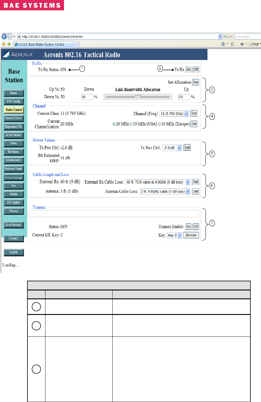
Base Station Radio Control Page
Table 0-4. Base Station Radio Control
Field/Control Description
1
Tx/Rx Status The Tx/Rx Status indicates if the user has
selected the Tx/Rx control on or off.
2
Tx/Rx On and Off
Buttons
Buttons to select the Tx/Rx function to be turned
on or off. When turned off the unit will not transmit
or receive.
3
Link Bandwidth
Allocation
The current link bandwidth allocation is shown in
percentage of upstream and downstream
allocation.
• Up % and Down % on the left displays the
current allocation of the network.
• Link Bandwidth Allocation Slide Bar –
method to adjust the allocation. The
Down and Up percentages on each side
of the slide bar displays the adjusted

Revision: I
CAGE Code: 0D0D0
ITAR CONTROLLED
23
BAE SYSTEMS PROPRIETARY INFORMATION
Use or disclosure of data contained on this sheet
is subject to the restriction on the title page.
Table 0-4. Base Station Radio Control
Field/Control Description
value.
• Set Allocation Button – changes the
current allocation to the new settings
displayed in the Down and Up boxes
adjacent to the slide bar.
4
Channel /
Channelization
Displays channel information for the base station.
• Current Channel – displays the current
channel of the base station.
• Channel (Freq) – drop down to choose a
different channel for the base station.
• Set Button – changes the current channel
of the base station to the channel
selected by the channel (freq) drop down.
• Current Channelization – displays the
current channelization of the radio. The
base station and subscriber stations need
to be configured for the same
channelization.
• Channelization Selection – Allows the
selection of the channelization. The
10MHz Europe is not currently enabled
in the product.
• Set Button – changes the current
channelization selected by the user.
5
Power Values
Allows the user to adjust the transmit power of the
radio.
• Tx Pwr Ctrl – the value on the left of the
screen shows the current setting. The
drop down on the right side of the screen
allows the user to choose a different
setting. Any grey value in the drop down
is not currently supported in the product.
• Set Button – changes the transmit power
control parameter to the chosen value
from the drop down.
• BS Estimated EIRP – the value is an
estimated EIRP based upon configuration
settings and received RSSI readings.
6
Cable Length
Allows the user to define certain cable length
values. The choices are defined on the Power
Settings configuration page by a privileged user.
• External Rx – the current cable length and
loss defined in the system for the external
receive cable.
• External Rx Cable Loss – drop down to
choose the receive cable length and loss
in dB for the external receive cable.
• Set Button – changes the external receive
cable loss parameter in the radio.
Revision: I
CAGE Code: 0D0D0
ITAR CONTROLLED
24
BAE SYSTEMS PROPRIETARY INFORMATION
Use or disclosure of data contained on this sheet
is subject to the restriction on the title page.
Table 0-4. Base Station Radio Control
Field/Control Description
• Antenna – the current cable length and
loss defined in the system for the antenna
cable.
• Antenna Cable Loss – drop down to
choose the antenna cable loss parameter.
• Set Button – changes the antenna cable
loss parameter in the radio.
7
Transec
Displays the settings for Transec capability.
• Status - Displays whether Transec is on
or off on the base station.
• Transec On/Off – buttons to turn Transec
on or off. The crypto user is the only user
that can turn Transec off.
• Current Effective Key – displays the key
slot of the current effective key. The
current effective key is selected on the
Admin page by the crypto officer.
• Key – drop down to select a key slot to
zeroize.
• Zeroize – button to initiate the zeroization
of the key slot selected in the key drop
down.
Revision: I
CAGE Code: 0D0D0
ITAR CONTROLLED
25
BAE SYSTEMS PROPRIETARY INFORMATION
Use or disclosure of data contained on this sheet
is subject to the restriction on the title page.
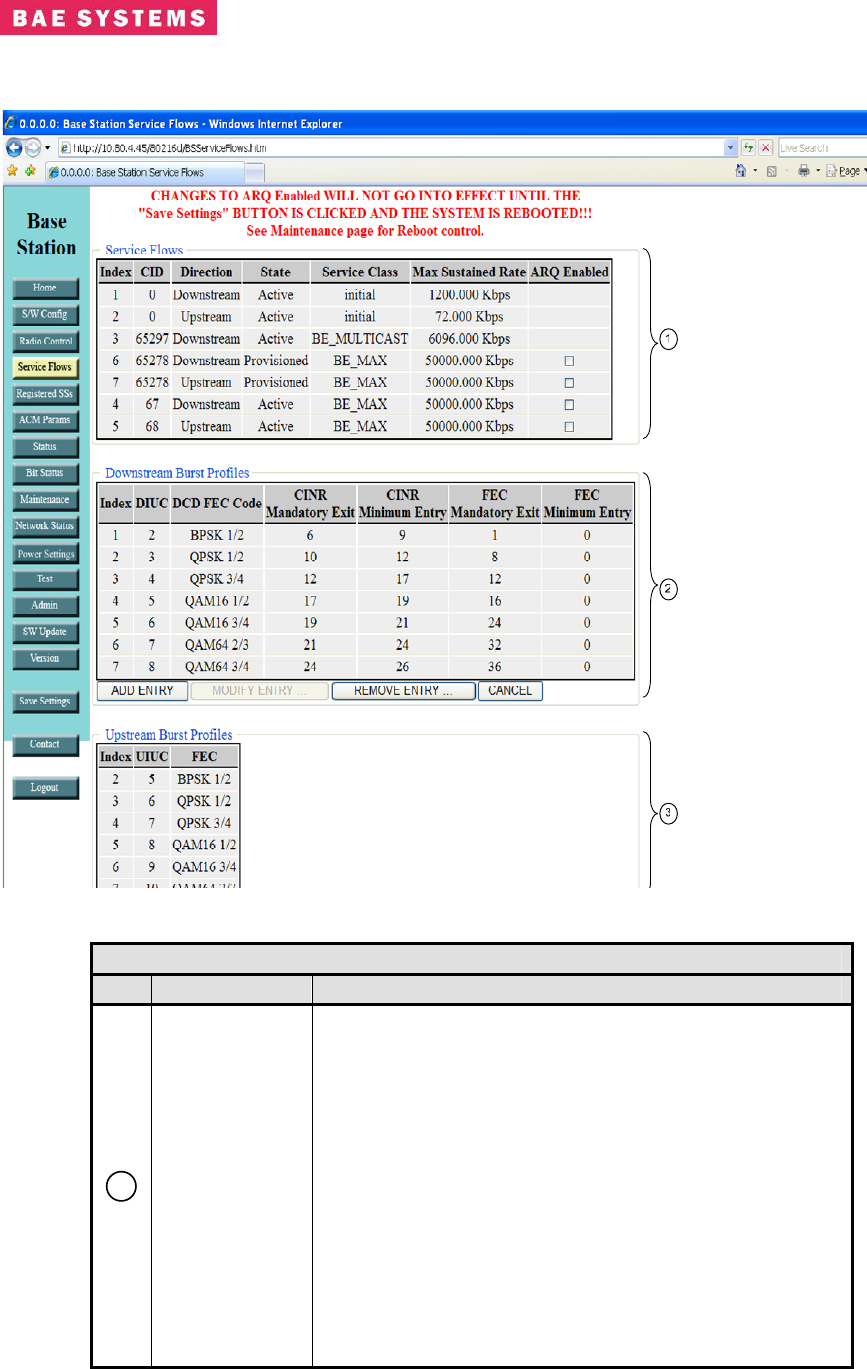
Base Station Service Flows
Table 0-5. Base Station Service Flow
Field Description
1
Service Flows
Displays every service flow that is currently configured in
the base station. Displays the following selected fields:
• Index - Actual index number assigned to the
service flow.
• CID - Basic CID for this service flow, corresponds
to basic CID in registered SS page.
• Direction - Direction is either upstream or
downstream. To create 1 duplex connection you
must configure an upstream and downstream
service flow.
• State - States can be Provisioned, Admitted, or
Active. Provisioned is a service flow that was
configured but the subscriber has not yet
established communication with the base station.
Admitted is a state in which a subscriber is
Revision: I
CAGE Code: 0D0D0
ITAR CONTROLLED
26
BAE SYSTEMS PROPRIETARY INFORMATION
Use or disclosure of data contained on this sheet
is subject to the restriction on the title page.
Table 0-5. Base Station Service Flow
Field Description
registered and allowed in the system but is not yet
flowing traffic. Active is a flow that currently has
traffic or the ability to pass traffic.
• Service Class - The textual name of a configured
service class that the node is using for QOS
parameters.
• Max Sustained Rate - QOS parameter that
defines the maximum sustained rate that will be
made available to the flow.
• ARQ Enabled – When the box is checked, ARQ is
enabled for the service flow. A reboot is
necessary after changing this value and saving
the settings.
2
Downstream
Burst Profiles
Displays the downstream burst profiles which define the
FEC types that the base station uses for transmissions.
• Add Entry Button allows for adding a new burst
profile for the network. Click on the button and
enter the fields. When the fields are complete
click on the add button to the right of the entry
fields.
• Modify Entry Button – The modify capability has is
enabled on the ACM parameter screen.
• Remove Entry Button allows for removing a burst
profile rule entry from the table. Click on the
button and then click on the remove button to the
right of the entry line to remove.
• Cancel Button allows for canceling the current add
or modify request.
Entry Fields:
• Index - the index into the burst profile table for the
entry. This field is not entered by the user.
• DIUC – the DIUC for the entry. This field is not
entered by the user.
• DCD FEC Code – drop down menu to choose the
FEC to use for the burst profile. This defines the
modulation type and forward error correction.
• CINR Mandatory Exit – Threshold value of CINR
in dB that is used as a decision point to exit the
use of this profile. Valid values are 1-65.
• CINR Minimum Entry - Threshold value of CINR in
dB that is used as a decision point to enter the
use of this profile. Valid values are 1-65.
• FEC Mandatory Exit – Threshold value of FEC
errors that is used as a decision point for exiting a
current modulation. The unit of this value is bits
per symbol.
• FEC Mandatory Entry – Threshold value of FEC
errors that is used as a decision point for entering
a modulation. The unit of this value is bits per
Revision: I
CAGE Code: 0D0D0
ITAR CONTROLLED
27
BAE SYSTEMS PROPRIETARY INFORMATION
Use or disclosure of data contained on this sheet
is subject to the restriction on the title page.
Table 0-5. Base Station Service Flow
Field Description
symbol.
3
Upstream
Burst Profiles
Displays the upstream burst profiles which define the FEC
types that the subscriber stations use for transmissions.
The current implementation uses the same values for
upstream as downstream for CINR and FEC entry and
exit.
Entry Fields (display only):
• Index - the index into the burst profile table for the
entry.
• UIUC – the UIUC for the entry.
• FEC – type of modulation and forward error
correction of the burst profile.
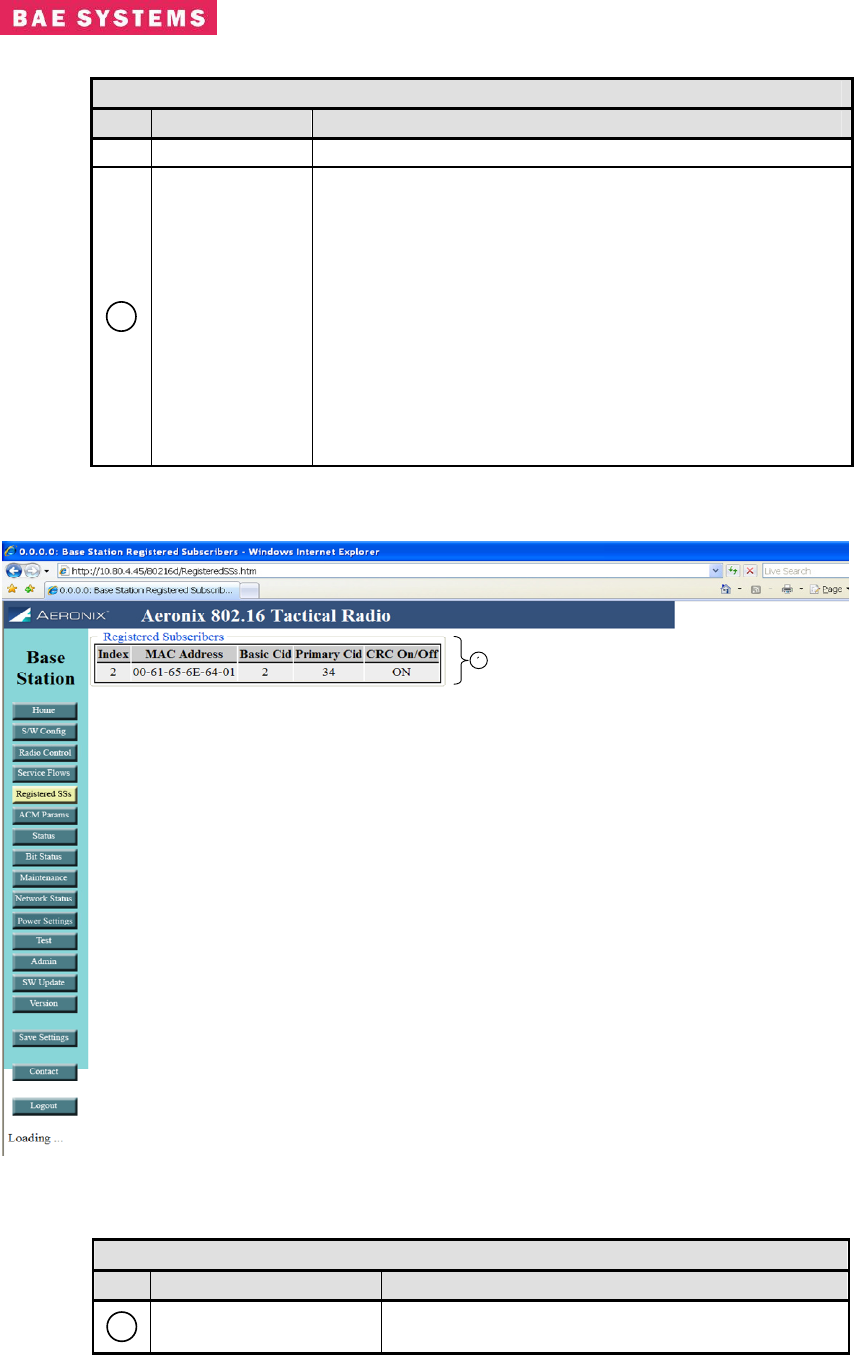
Base Station Registered SS Page
Table 0-6. Base Station Registered SS
Field Description
1
Registered SSs
Display
Displays all subscriber stations which are
registered with the base station. Fields that are
Revision: I
CAGE Code: 0D0D0
ITAR CONTROLLED
28
BAE SYSTEMS PROPRIETARY INFORMATION
Use or disclosure of data contained on this sheet
is subject to the restriction on the title page.
Table 0-6. Base Station Registered SS
Field Description
displayed include:
• Index - Actual index numbered assigned
to the entry.
• MAC Address - IEEE 802.16 MAC
address of subscriber station.
• Basic Cid - Basic Connection ID of the
subscriber station, used to flow traffic
data between the base station and
subscriber station.
• Primary Cid - Primary Connection ID of
the subscriber station, used to flow
management data between the base
station and subscriber station.
• CRC On/Off - Indicates if CRC
mechanism is on or off for the subscriber
station. CRC covers the entire contents
of each PDU within the connections.
Revision: I
CAGE Code: 0D0D0
ITAR CONTROLLED
29
BAE SYSTEMS PROPRIETARY INFORMATION
Use or disclosure of data contained on this sheet
is subject to the restriction on the title page.
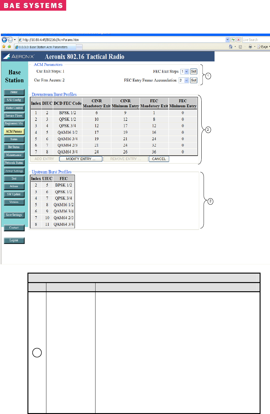
Base Station ACM Parameters Page
Table 0-7. Base Station ACM Page
Field Description
1
ACM
Parameters
Displays the adjustable ACM parameters which includes
the following selected fields:
• Current Exit Steps – Displays the current number
of modulation steps to take when exiting the
current modulation.
• FEC Exit Steps – Drop down menu for selecting
the number of steps to take in the modulation
table when exiting the current modulation due to
FEC errors occurring.
• Set Button – Sets the exit steps selected in the
FEC Exit Steps drop down.
• Current Frame Accumulation – Displays the
current number of frames to accumulate before
deciding to adjust the modulation up or down.
• FEC Entry Frame Accumulation – Drop down
menu for selecting the number of frame to
Revision: I
CAGE Code: 0D0D0
ITAR CONTROLLED
30
BAE SYSTEMS PROPRIETARY INFORMATION
Use or disclosure of data contained on this sheet
is subject to the restriction on the title page.
Table 0-7. Base Station ACM Page
Field Description
accumulate before adjusting the modulation up or
down.
• Set Button – Sets the FEC Entry Frame
Accumulation selected in the drop down menu.
2
Downstream
Burst Profiles
Displays the downstream burst profiles which define the
FEC types that the base station uses for transmissions as
well as the entry and exit threshold for switching
modulations.
• Add Entry Button – the button is enabled on the
service flow screen.
• Modify Entry Button – The modify capability allows
the user to modify the entry and exit thresholds for
switching modulations.
• Remove Entry Button - the button is enabled on
the service flow screen.
• Cancel Button allows for canceling the current
modify request.
Entry Fields:
• Index - the index into the burst profile table for the
entry. This field is not entered by the user.
• DIUC – the DIUC for the entry. This field is not
entered by the user.
• DCD FEC Code – drop down menu to choose the
FEC to use for the burst profile. This defines the
modulation type and forward error correction.
• CINR Mandatory Exit – Threshold value of CINR
in dB that is used as a decision point to exit the
use of this profile. Valid values are 1-65.
• CINR Minimum Entry - Threshold value of CINR in
dB that is used as a decision point to enter the
use of this profile. Valid values are 1-65.
• FEC Mandatory Exit – Threshold value of FEC
errors that is used as a decision point for exiting a
current modulation. The unit of this value is bits
per symbol.
• FEC Mandatory Entry – Threshold value of FEC
errors that is used as a decision point for entering
a modulation. The unit of this value is bits per
symbol.
3
Upstream
Burst Profiles
Displays the upstream burst profiles which define the FEC
types that the subscriber stations use for transmissions.
The current implementation uses the same values for
upstream as downstream for CINR and FEC entry and
exit.
Entry Fields (display only):
• Index - the index into the burst profile table for the
entry.
• UIUC – the UIUC for the entry.
Revision: I
CAGE Code: 0D0D0
ITAR CONTROLLED
31
BAE SYSTEMS PROPRIETARY INFORMATION
Use or disclosure of data contained on this sheet
is subject to the restriction on the title page.
Table 0-7. Base Station ACM Page
Field Description
• FEC – type of modulation and forward error
correction of the burst profile.
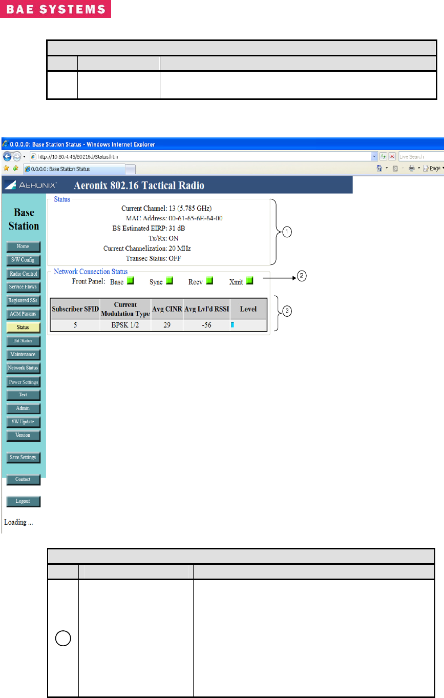
Base Station Status Page
Table 0-8. Base Station Status
Field Description
1
Status
Status displays a subset of current settings.
• Current Channel – the current 802.16
specified channel that the base station
uses for transmit and receive.
• MAC Address – The IEEE 802.16 MAC
address of the base station.
• BS Estimated EIRP – Displays the
estimated EIRP of the base station based
upon user configured gain a loss values.
Revision: I
CAGE Code: 0D0D0
ITAR CONTROLLED
32
BAE SYSTEMS PROPRIETARY INFORMATION
Use or disclosure of data contained on this sheet
is subject to the restriction on the title page.
Table 0-8. Base Station Status
Field Description
• Tx/Rx - Status indicating whether the base
station Tx/Rx capability is currently on or
off.
• Current Channelization – displays the
channelization of the base station.
• Transec Status – displays the status of
Transec (on or off).
2
Front Panel
Displays the PHY status lights on an interval
basis. The lights should match those on the front
of the unit but, could be delayed slightly due to
sample rate.
3
Status Table
Displays the status of each subscriber connection.
• Subscriber SFID - Contains the service
flow ID of the downstream service flow to
the subscriber.
• Current Modulation Type – Contains the
current modulation/FEC type for the
subscriber connection. The display show
the modulation of the receive frame at the
time sampled.
• Avg CINR – Displays the average CINR
value for the subscriber connection.
• Avg Leveled RSSI – Displays the average
leveled RSSI value for the subscriber
connection. The value is calculated from
the receive loss and gain values entered
by the user and the actual RSSI value
received by the PHY.
• Level – Displays the level of the RSSI.
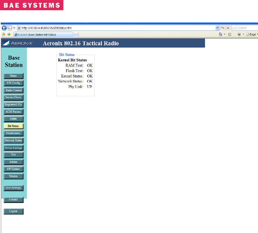
Base Station Bit Status
This page shows the results of the bit tests executed at startup. The names and number of tests
may change due to FIPS requirement changes.
Revision: I
CAGE Code: 0D0D0
ITAR CONTROLLED
33
BAE SYSTEMS PROPRIETARY INFORMATION
Use or disclosure of data contained on this sheet
is subject to the restriction on the title page.
Revision: I
CAGE Code: 0D0D0
ITAR CONTROLLED
34
BAE SYSTEMS PROPRIETARY INFORMATION
Use or disclosure of data contained on this sheet
is subject to the restriction on the title page.
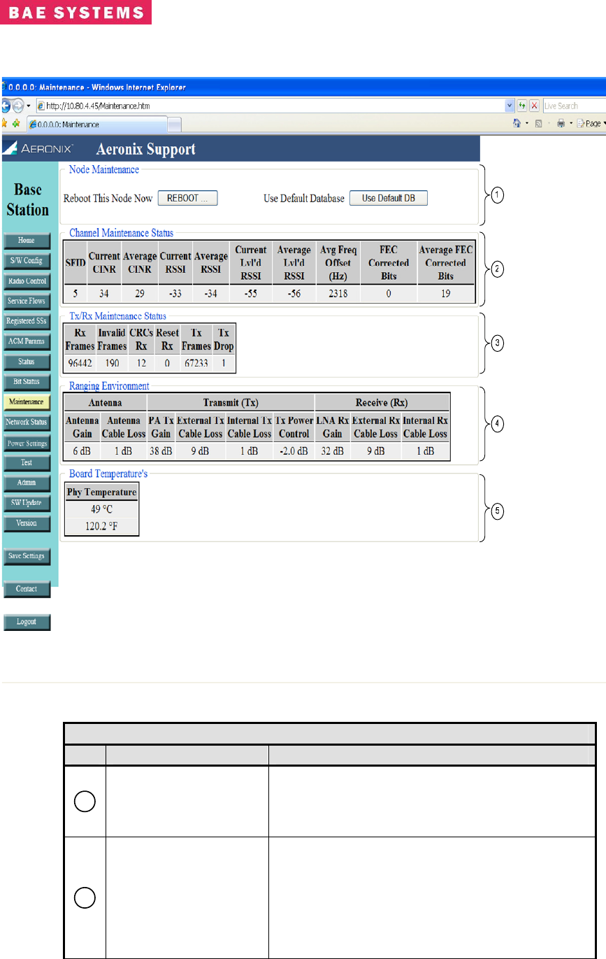
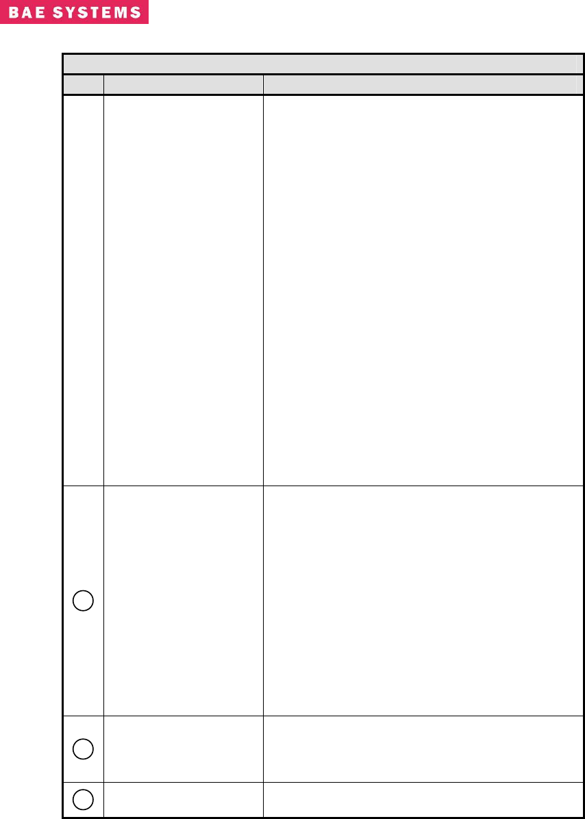
Base Station Maintenance Page
Table 0-9. Base Station Maintenance
Field/Control Description
1
Node Maintenance
Provides a method of rebooting the system
without a power cycle.
Provides a method to revert back to the default
database.
2
Channel Maintenance
Status
Provides some additional values on a connection
basis for debugging and antenna pointing
purposes.
• Current CINR – the instantaneous CINR
for the connection.
• Average CINR – the average CINR of the
connection over a period of received
Revision: I
CAGE Code: 0D0D0
ITAR CONTROLLED
35
BAE SYSTEMS PROPRIETARY INFORMATION
Use or disclosure of data contained on this sheet
is subject to the restriction on the title page.
Table 0-9. Base Station Maintenance
Field/Control Description
frames.
• Current RSSI – the instantaneous RSSI
for the connection.
• Average RSSI – the average RSSI of the
connection over a period of received
frames.
• Current Leveled RSSI – the current
leveled RSSI value for the connection.
The leveled RSSI reflects the loss and
gain values from the output of the PHY
(including the transmit power attenuation
value) to the PA/LNA.
• Average Leveled RSSI – the average
leveled RSSI value of the connection over
a period of received frames.
• Average Frequency Offset – the average
frequency offset of the connection over a
period of received frames.
• FEC Corrected Bits – the instantaneous
forward error correction corrected bits
• Average FEC Corrected Bits – the
average forward error correction
corrected bits for the connection
3
Tx/Rx Maintenance
Status
Provides the Tx and Rx frame counts and well as
error counts for debugging.
• Rx Frames – the number of frames
received
• Invalid Frames – the number of frames
received that were invalid
• CRCs Rx – the number of CRCs received
• Reset Rx – the number of times the
receive path has been reset
• Tx Frames – the number of frame
transmitted
• Tx Drop – the number of transmit frames
that were dropped by the classifiers
4
Ranging Environment
Provides the gain and loss settings used for
ranging purposes and EIRP calculations. These
settings are configured on the Power Settings and
Radio Control pages.
5
PHY Temperature Provides the temperature of the PHY card inside
of the radio box.
Revision: I
CAGE Code: 0D0D0
ITAR CONTROLLED
36
BAE SYSTEMS PROPRIETARY INFORMATION
Use or disclosure of data contained on this sheet
is subject to the restriction on the title page.
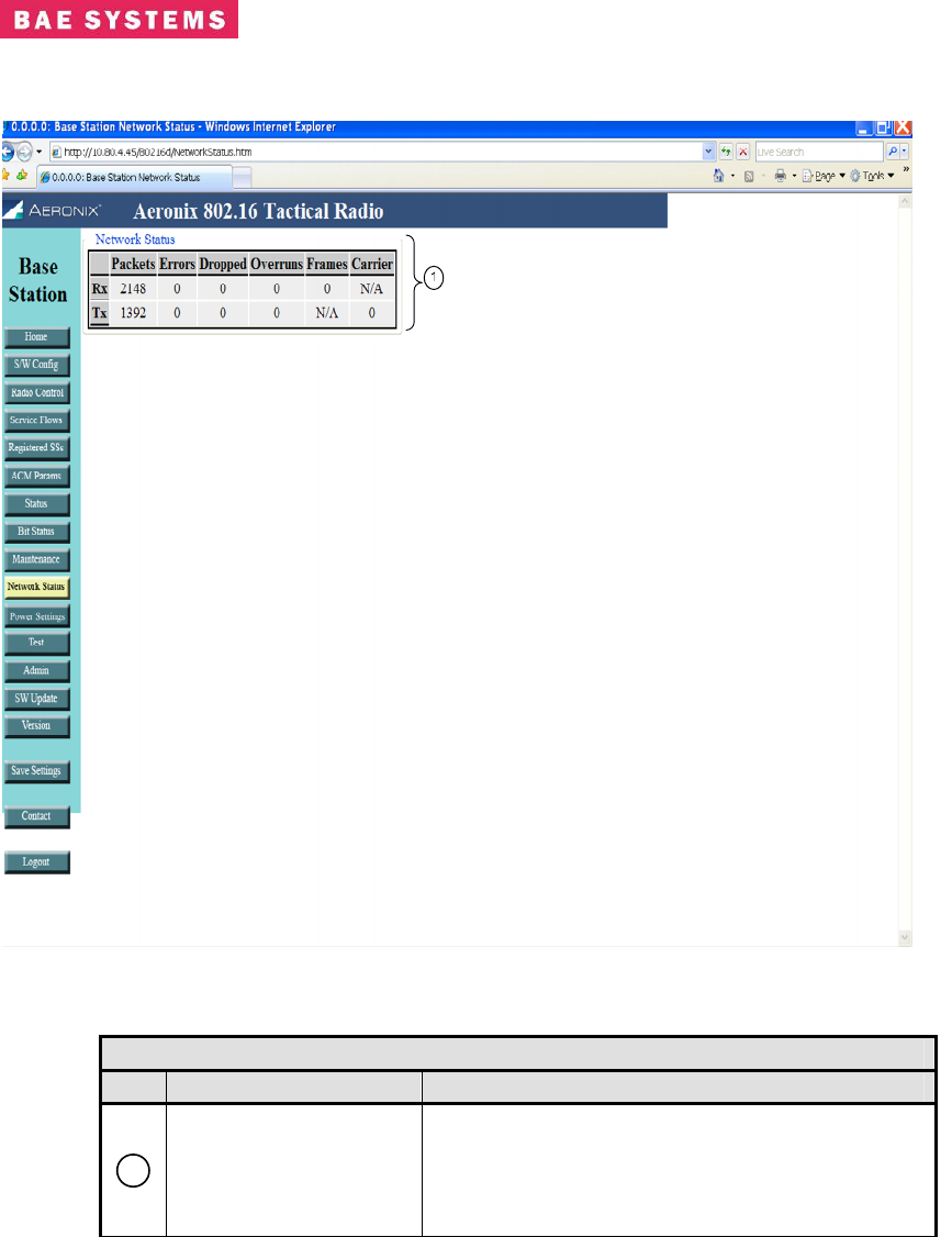
Base Station Network Status Page
Table 0-10. Base Station Network Status
Field/Control Description
1
Network Status
Displays the number of transmitted and received
frames on the network side of the radio. This
reflects the eth0 interface in a non-bridging
configuration and the mybridge interface in a
bridging configuration.
Revision: I
CAGE Code: 0D0D0
ITAR CONTROLLED
37
BAE SYSTEMS PROPRIETARY INFORMATION
Use or disclosure of data contained on this sheet
is subject to the restriction on the title page.
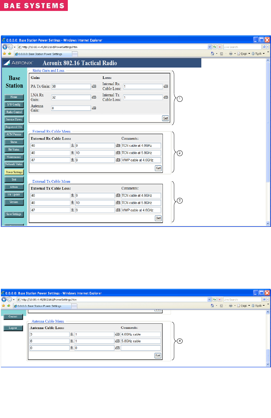
Base Station Power Settings Page
Revision: I
CAGE Code: 0D0D0
ITAR CONTROLLED
38
BAE SYSTEMS PROPRIETARY INFORMATION
Use or disclosure of data contained on this sheet
is subject to the restriction on the title page.
Table 0-11. Base Station Power Settings Page
Field/Control Description
1
Static Gain and Loss
• PA Tx Gain – the transmit gain of the
power amplifier located outside of the
radio
• LNA Rx Gain – the receive gain of the low
noise amplifier located outside of the
radio
• Antenna Gain – the gain of the antenna
located outside of the radio
• Internal Rx Cable Loss - the loss of the
cable and any other components in the
receive path inside of the radio box but
external to the PHY
• Internal Tx Cable Loss – the loss of the
cable and any other components in the
transmit path inside of the radio box but
external to the PHY
• Attenuation – the change in transmit
power of the PHY
2
External Rx Cable
Menu
• Contains up to three entries for external
receive cable loss values. This value
represents the receive cable between the
radio unit and the receive LNA. The user
inputs the length of the cable in feet and
the loss value in dB. The comment field
is optional. The first value entered will be
the default value that gets used initially for
ranging, leveled RSSI and EIRP
calculations. To change the values used
go to the Radio Control page.
3
External Tx Cable
Menu
• Contains up to three entries for the
transmit cable loss values. This value
represents the cable between the radio
unit and the transmit power amplifier. The
user inputs the length of the cable in feet
and the loss value in dB. The comment
field is optional.
4
Antenna Cable Menu
• Contains up to three entries for the
antenna cable loss values. This value
represents the cable between the power
head and the antenna. The user inputs
the length of the cable in feet and the loss
value in dB. The comment field is
optional.
The Set button in each section is used to place the current values entered into the
database.
Revision: I
CAGE Code: 0D0D0
ITAR CONTROLLED
39
BAE SYSTEMS PROPRIETARY INFORMATION
Use or disclosure of data contained on this sheet
is subject to the restriction on the title page.
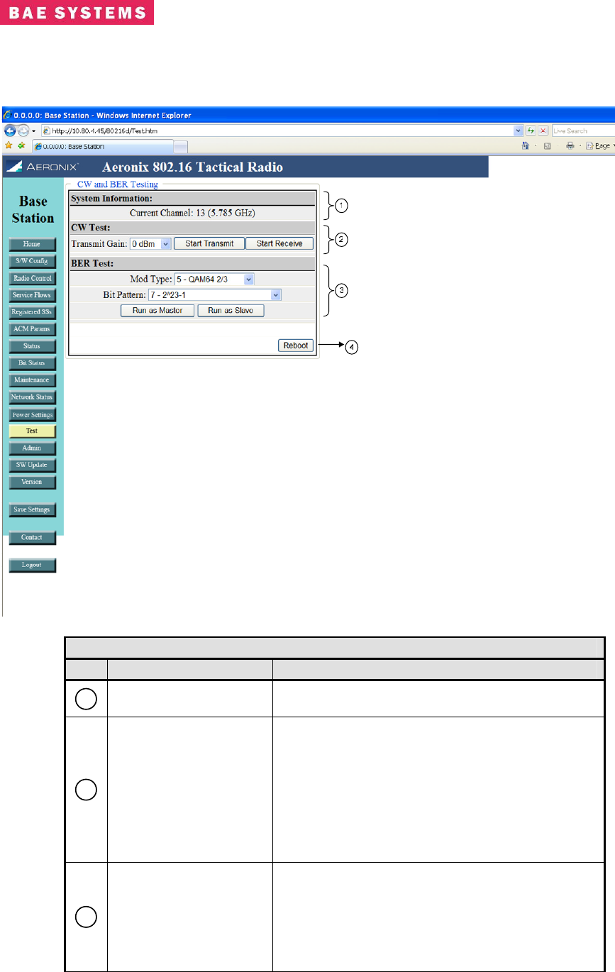
Base Station Test Page
Table 0-12. Base Station Test Page
Field/Control Description
1
System Information Provides the current channel information of the
radio
2
CW Test
Provides the capability to execute a continuous
waveform test.
• Transmit Gain – Selection of the transmit
gain desired from the pull down menu.
• Start Transmit – Starts the transmission of
a CW
• Start Receive – Starts the receive of a
CW
3
BER Test
Provides the capability to execute a bit error rate
test.
• Mod Type – Defines the modulation type
used during the test.
• Bit Pattern – Define the bit patter used
during the test.