BAE Systems WINTLAW 802.16 Wideband Transceiver User Manual XX XXXX Exhibit Cover
BAE Systems 802.16 Wideband Transceiver XX XXXX Exhibit Cover
Contents
- 1. Manual 1 of 2
- 2. Manual 2 of 2
Manual 2 of 2
Revision: I
CAGE Code: 0D0D0
ITAR CONTROLLED
40
BAE SYSTEMS PROPRIETARY INFORMATION
Use or disclosure of data contained on this sheet
is subject to the restriction on the title page.
Table 0-12. Base Station Test Page
Field/Control Description
• Run as Master – Starts the test with the
radio as the master.
• Run as Slave – Starts the test with the
radio as the slave.
4
Control Buttons • Reboot – reboots the system.
Notes:
Executing any of the tests from this page requires a reboot of the system to return the
radio to normal operation.
Base Station Admin Page
Revision: I
CAGE Code: 0D0D0
ITAR CONTROLLED
41
BAE SYSTEMS PROPRIETARY INFORMATION
Use or disclosure of data contained on this sheet
is subject to the restriction on the title page.
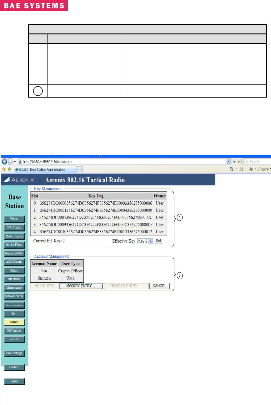
Table 0-13. Base Station Admin Page
Field/Control Description
1
Key Management
Provides the crypto user with the capability to
choose the active key slot by selecting the slot
from the drop down menu and clicking the set
button.
2
Account Management Provides each user with the capability to change
their account passwords.
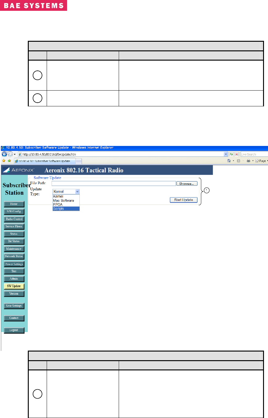
Base Station Software Update Page
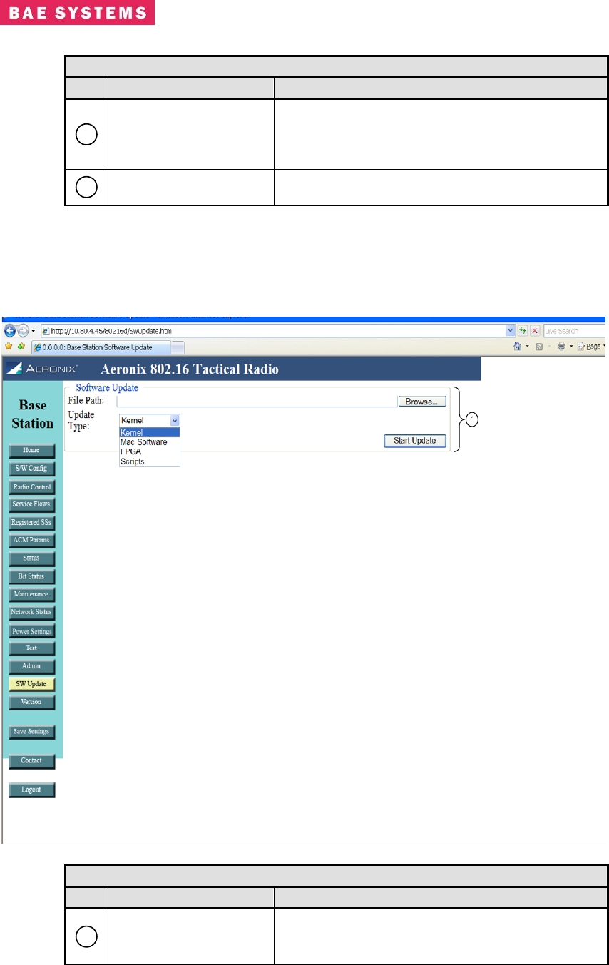
Table 0-14. Base Station Software Update Page
Field/Control Description
1
Software Update
Provides the crypto user with the capability to
update the software on the unit.
• File Path – location of the new file to
Revision: I
CAGE Code: 0D0D0
ITAR CONTROLLED
42
BAE SYSTEMS PROPRIETARY INFORMATION
Use or disclosure of data contained on this sheet
is subject to the restriction on the title page.
Table 0-14. Base Station Software Update Page
Field/Control Description
update on the unit.
• Update type – the type of file on the unit
to update.
• Start update button – initiates the update
process
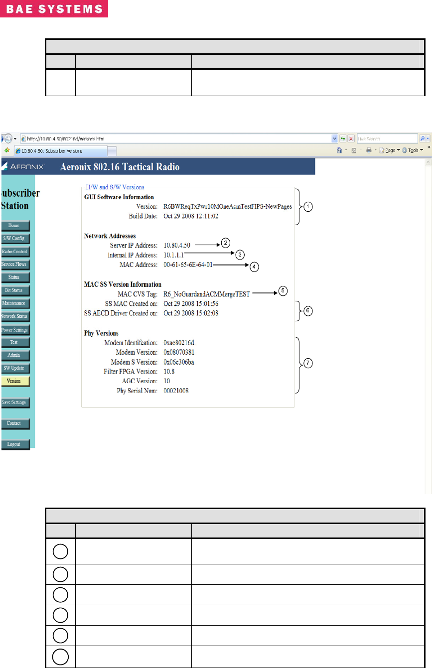
Base Station Version Page
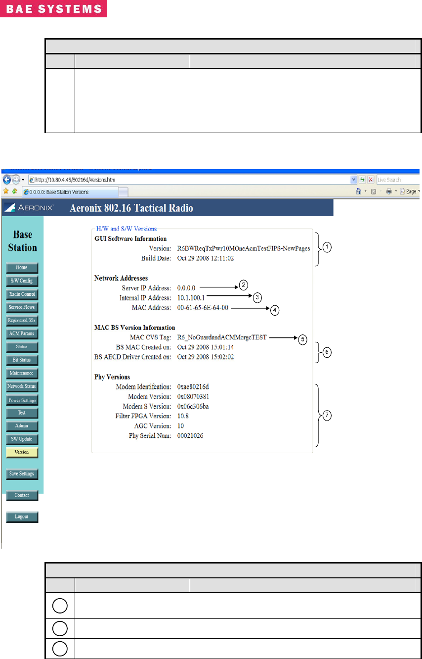
Table 0-15. Base Station Version Page
Field/Control Description
1
GUI Software
Information Date and Time of current GUI build
2
Server IP Address Ethernet IP Address of Base Station
3
Internal IP Address MAC S/W network interface IP Address
Revision: I
CAGE Code: 0D0D0
ITAR CONTROLLED
43
BAE SYSTEMS PROPRIETARY INFORMATION
Use or disclosure of data contained on this sheet
is subject to the restriction on the title page.
Table 0-15. Base Station Version Page
Field/Control Description
4
MAC Address MAC H/W Address of Base Station network
interface
5
MAC CVS Tag BS MAC S/W current version
6
BS MAC Dates BS MAC modules build date and time
7
Phy Versions Firmware versions for PHY and Serial Number of
PHY hardware
Revision: I
CAGE Code: 0D0D0
ITAR CONTROLLED
44
BAE SYSTEMS PROPRIETARY INFORMATION
Use or disclosure of data contained on this sheet
is subject to the restriction on the title page.
Base Station Contact Page
The contact page provides contact information for the 802.16 product.
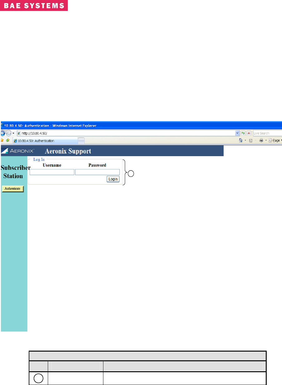
Subscriber Station Login Page
The subscriber station requires a login for access to configuration screens. The subscriber station
contains one crypto officer login and one user login. Access to certain configuration items is
restricted for the user login.
1
Table 0-16. Subscriber Station Login Page
Link Description
1
Login Location to provide the username and password
Revision: I
CAGE Code: 0D0D0
ITAR CONTROLLED
45
BAE SYSTEMS PROPRIETARY INFORMATION
Use or disclosure of data contained on this sheet
is subject to the restriction on the title page.
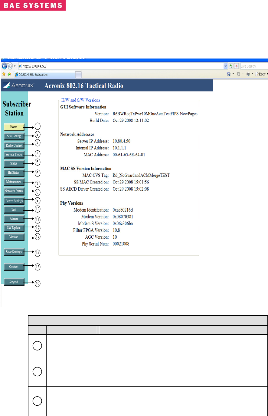
Subscriber Station Home Page
The subscriber station home page contains HTML links to the status and configuration pages for
the 802.16 radio product family.
1
Table 0-17. Subscriber Station Home Page
Field/Control Description
1
Home
HTML Link to the Home page that displays network access
information as well as the hardware and software version
information.
2
SW Config
HTML Link to the software configuration page; the
configuration page contains the needed tools to define and
configure the external systems interaction with the 802.16
radio.
3
Radio Control
HTML Link to the Radio Control Page; the radio control
page contains channel, initial ranging and TRANSEC
parameters. The user has limited capabilities for TRANSEC
and keying.
Revision: I
CAGE Code: 0D0D0
ITAR CONTROLLED
46
BAE SYSTEMS PROPRIETARY INFORMATION
Use or disclosure of data contained on this sheet
is subject to the restriction on the title page.
Table 0-17. Subscriber Station Home Page
Field/Control Description
4
Service Flow
HTML Link to the Service Flow page; the service flow page
displays the current service flows within the node and the
current state of each service flow; this page is used to
enable or disable the ARQ.
5
Status HTML Link to the Status page; the status page contains
operating status of the radio.
6
Bit Status HTML Link to the Bit Status results page. This page
provides results of the test executed at startup.
7
Maintenance HTML Link to the Maintenance; the maintenance page
contains information for debugging and antenna pointing.
8
Network Status HTML Link to the Network Status page; this page provides
transmit and receive status for the Ethernet interface.
9
Power Settings
HTML link to the Power Settings page; this page provides
the capability to enter gain settings and cable loss settings
for ranging purposes.
10
Test HTML Link to the Test page for running either a CW test or
BER test.
11
Admin
HTML Link to the administration page. This page provides
TRANSEC key selection and password changing
capabilities. The user login does not have access to the
TRANSEC key selection functions.
12
Software Update
HTML Link to the software update page. This page
provides the capability to update the software to the crypto
officer only.
13
Version HTML Link to Version page; the version page contains the
hardware and software version information.
14
Save Settings
Save Settings control key will save the current selected
values in each GUI screen to the Base Station database.
Additions, modifications or deletions are not
permanently saved to the database unless this control
key is selected.
15
Contact HTML Link to the Contact Page; the contact page contains
Aeronix Inc. contact information.
16
Logout The logout control key logs the current user out of the
system.
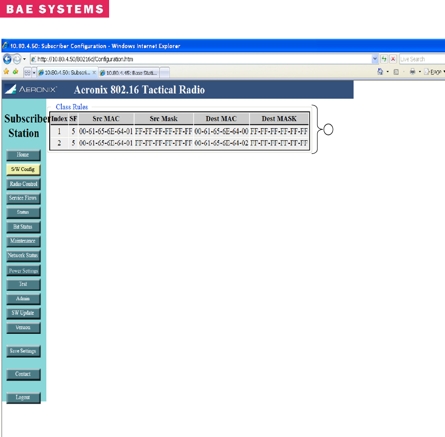
Subscriber Station Software Configuration Page
This page is for display only and shows the classifier rules received from the base station.
Revision: I
CAGE Code: 0D0D0
ITAR CONTROLLED
47
BAE SYSTEMS PROPRIETARY INFORMATION
Use or disclosure of data contained on this sheet
is subject to the restriction on the title page.
1
Revision: I
CAGE Code: 0D0D0
ITAR CONTROLLED
48
BAE SYSTEMS PROPRIETARY INFORMATION
Use or disclosure of data contained on this sheet
is subject to the restriction on the title page.
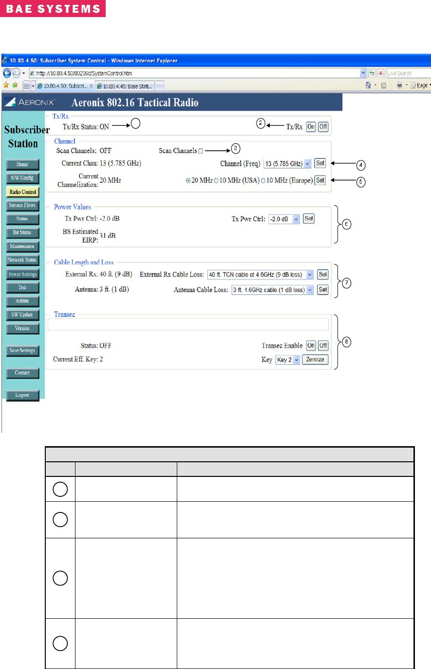
Subscriber Station Radio Control Page
1
Table 0-18. Subscriber Station Radio Control Page
Field/Control Description
1
Tx/Rx Status The Tx/Rx Status indicates if the user has selected
the Tx/Rx control on or off.
2
Tx/Rx On and Off
Buttons
Buttons to select the Tx/Rx function to be turned on
or off. When turned off the subscriber will not
transmit or receive.
3
Scan Channels
Scan Channels allows the subscriber to scan all
channels in a frequency band searching for a valid
base station signal. Select the box to turn scan
channels on. The scan channels display of the left
of the screen shows the current scan channels
setting. If scan channels is off the subscriber only
uses the current channel.
4
Channel
Displays channel information for the subscriber
station.
• Current Channel – displays the current
channel of the subscriber station.

Revision: I
CAGE Code: 0D0D0
ITAR CONTROLLED
49
BAE SYSTEMS PROPRIETARY INFORMATION
Use or disclosure of data contained on this sheet
is subject to the restriction on the title page.
Table 0-18. Subscriber Station Radio Control Page
Field/Control Description
• Channel (Freq) – drop down to choose a
different channel for the subscriber station.
• Set Button – changes the current channel of
the subscriber station to the channel
selected by the channel (freq) drop down.
5
Channelization
Allows the user to choose the channelization of the
radio.
• Cur Channelization – Displays the current
channelization setting of the radio.
• Channelization Selection – Allows the
selection of channelization. The 10MHz
Europe is not enabled in this release.
• Set Button – changes the current
channelization selected by the user.
6
Power Values
Allows the user to adjust the transmit power of the
radio.
• Tx Pwr Ctrl – the value on the left of the
screen shows the current setting. The drop
down on the right side of the screen allows
the user to choose a different setting. Any
grey value in the drop down is not currently
supported in the product.
• Set Button – changes the transmit power
control parameter to the chosen value from
the drop down.
• BS Estimated EIRP – the value is an
estimated EIRP based upon configuration
settings and received RSSI readings.
7
Cable Length
Allows the user to define certain cable length
values. The choices are defined on the Power
Settings configuration page by a privileged user.
• External Rx – the current cable length and
loss defined in the system for the external
receive cable.
• External Rx Cable Loss – drop down to
choose the receive cable length and loss in
dB for the external receive cable.
• Set Button – changes the external receive
cable loss parameter in the radio.
• Antenna – the current cable length and loss
defined in the system for the antenna cable.
• Antenna Cable Loss – drop down to choose
the antenna cable loss parameter.
• Set Button – changes the antenna cable
loss parameter in the radio.
8
Transec
Displays the settings for Transec capability.
• Status - Displays whether Transec is on or
off on the base station.
Revision: I
CAGE Code: 0D0D0
ITAR CONTROLLED
50
BAE SYSTEMS PROPRIETARY INFORMATION
Use or disclosure of data contained on this sheet
is subject to the restriction on the title page.
Table 0-18. Subscriber Station Radio Control Page
Field/Control Description
• Transec On/Off – buttons to turn Transec on
or off. The crypto user is the only user that
can turn Transec off.
• Current Effective Key – displays the key slot
of the current effective key. The current key
is selected on the Admin page by the crypto
officer.
• Key – drop down to select a key slot to
zeroize.
• Zeroize – button to initiate the zeroization of
the key slot selected in the key drop down.
Revision: I
CAGE Code: 0D0D0
ITAR CONTROLLED
51
BAE SYSTEMS PROPRIETARY INFORMATION
Use or disclosure of data contained on this sheet
is subject to the restriction on the title page.
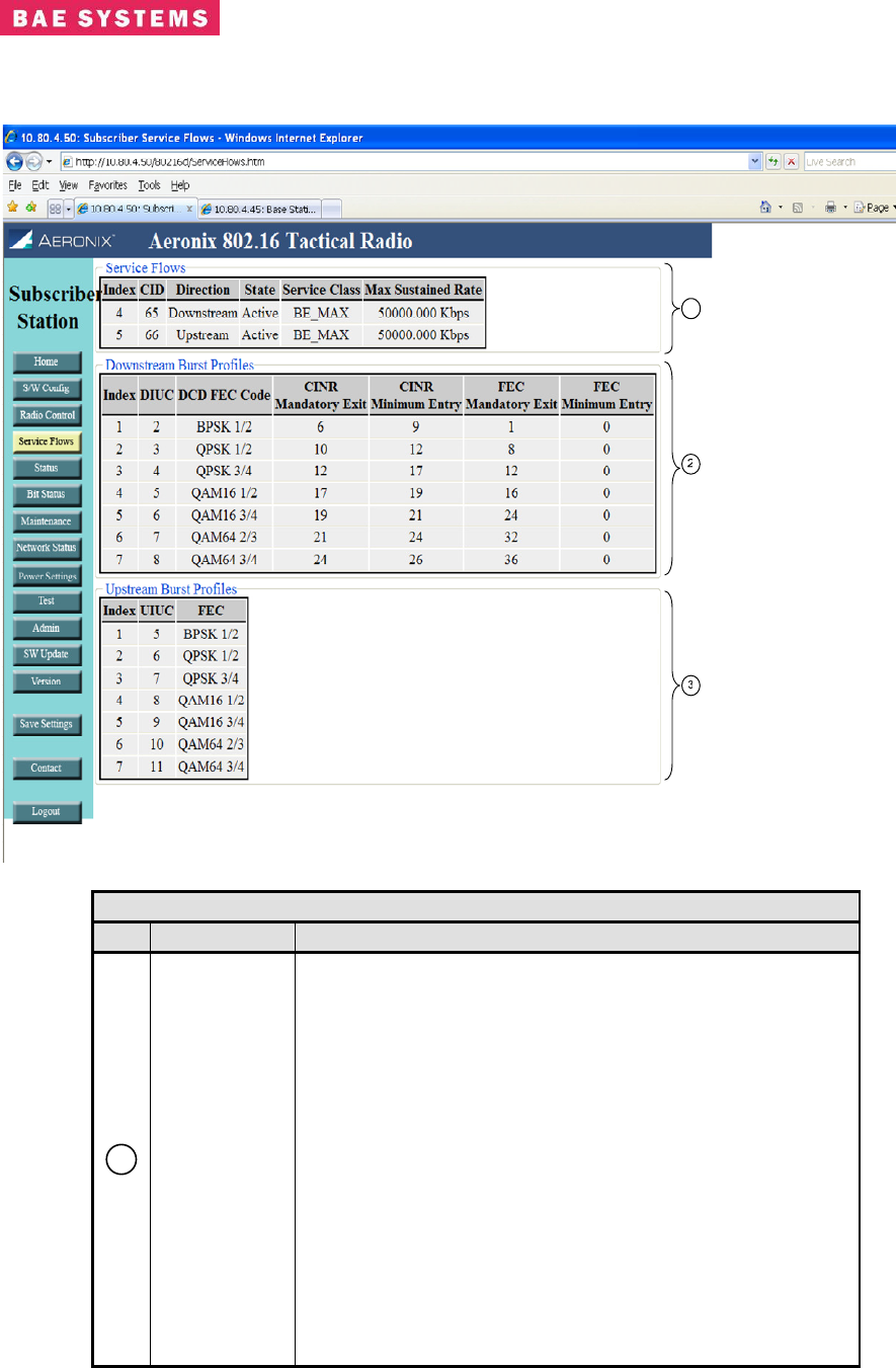
Subscriber Station Service Flow Page
1
Table 0-19. Subscriber Station Service Flow Page
Field Description
1
Service
Flows
Displays every service flow that is currently configured in the
base station for the subscriber station. Displays the
following fields:
• Index - Actual index number assigned to the service
flow.
• CID - Basic CID for this service flow.
• Direction - Direction is either upstream or
downstream.
• State - States can be Provisioned, Admitted, or
Active. Provisioned is a service flow that was
configured but the subscriber has not yet
established communication with the base station.
Admitted is a state in which a subscriber is
registered and allowed in the system but is not yet
flowing traffic. Active is a flow that currently has
traffic or the ability to pass traffic.
• Service Class - The textual name of a configured

Revision: I
CAGE Code: 0D0D0
ITAR CONTROLLED
52
BAE SYSTEMS PROPRIETARY INFORMATION
Use or disclosure of data contained on this sheet
is subject to the restriction on the title page.
Table 0-19. Subscriber Station Service Flow Page
Field Description
service class that the node is using for QOS
parameters.
• Max Sustained Rate - QOS parameter that defines
the maximum sustained rate that will be made
available to the flow.
2
Downstream
Burst Profiles
Displays the downstream burst profiles which define the
FEC types that the base station uses for transmissions.
These fields are configured on the base station.
Entry Fields (display only):
• Index - the index into the burst profile table for the
entry. This field is not entered by the user.
• DIUC – the DIUC for the entry. This field is not
entered by the user.
• DCD FEC Code – drop down menu to choose the
FEC to use for the burst profile. This defines the
modulation type and forward error correction.
• CINR Mandatory Exit – Threshold value of CINR in
dB that is used as a decision point to exit the use of
this profile. Valid values are 1-65.
• CINR Minimum Entry - Threshold value of CINR in
dB that is used as a decision point to enter the use
of this profile. Valid values are 1-65.
• FEC Mandatory Exit – Threshold value of FEC
errors that is used as a decision point for exiting a
current modulation. The unit of this value is bits per
symbol.
• FEC Mandatory Entry – Threshold value of FEC
errors that is used as a decision point for entering a
modulation. The unit of this value is bits per
symbol.
3
Upstream
Burst Profiles
Displays the upstream burst profiles which define the FEC
types that the subscriber stations use for transmissions.
The current implementation uses the same values for
upstream as downstream for CINR and FEC entry and exit.
Entry Fields (display only):
• Index - the index into the burst profile table for the
entry.
• UIUC – the UIUC for the entry.
FEC – type of modulation and forward error correction
of the burst profile.
Revision: I
CAGE Code: 0D0D0
ITAR CONTROLLED
53
BAE SYSTEMS PROPRIETARY INFORMATION
Use or disclosure of data contained on this sheet
is subject to the restriction on the title page.
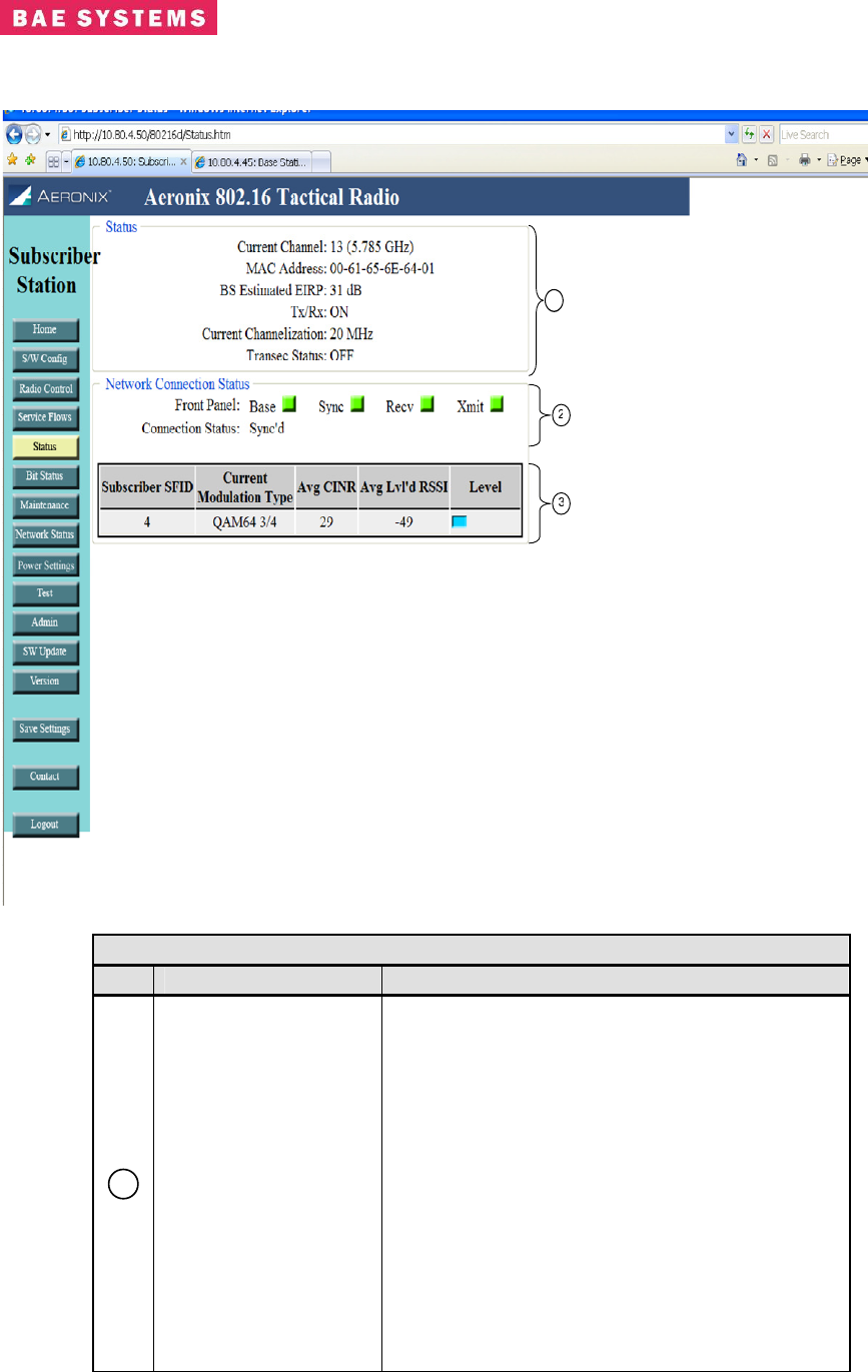
Subscriber Station Status Page
1
Table 0-20. Subscriber Station Status Page
Field/Control Description
1
Status
Status displays a subset of current settings.
• Current Channel – the current 802.16
specified channel that the subscriber
station uses for transmit and receive in
scan channels is disabled.
• MAC Address – The IEEE 802.16 MAC
address of the subscriber station.
• BS Estimated EIRP – Displays the
estimated EIRP of the subscriber station
based upon user configured gain a loss
values.
• Tx/Rx - Status indicating whether the
base station Tx/Rx capability is currently
on or off.
• Current Channelization– displays the
Revision: I
CAGE Code: 0D0D0
ITAR CONTROLLED
54
BAE SYSTEMS PROPRIETARY INFORMATION
Use or disclosure of data contained on this sheet
is subject to the restriction on the title page.
Table 0-20. Subscriber Station Status Page
Field/Control Description
channelization of the subscriber station.
• Transec Status – displays the current
status of Transec (on.off)
2
Network Connection
Status
• Front Panel - Displays the PHY status
lights on an interval basis.
• Connection Status – The status of the
connection from the perspective of the
MAC.
3
Status Table
Displays the status of each subscriber connection.
• Subscriber SFID - Contains the service
flow ID of the downstream service flow to
the subscriber.
• Current Modulation Type – Contains the
current modulation/FEC type for the
receive connection. The display show the
modulation of the receive frame at the
time sampled.
• Avg CINR – Displays the average CINR
value for the receive connection.
• Avg Leveled RSSI – Displays the average
leveled RSSI value for the receive
connection. The value is calculated from
the receive loss and gain values entered
by the user and the actual RSSI value
received by the PHY.
• Level – Displays the level of the RSSI.
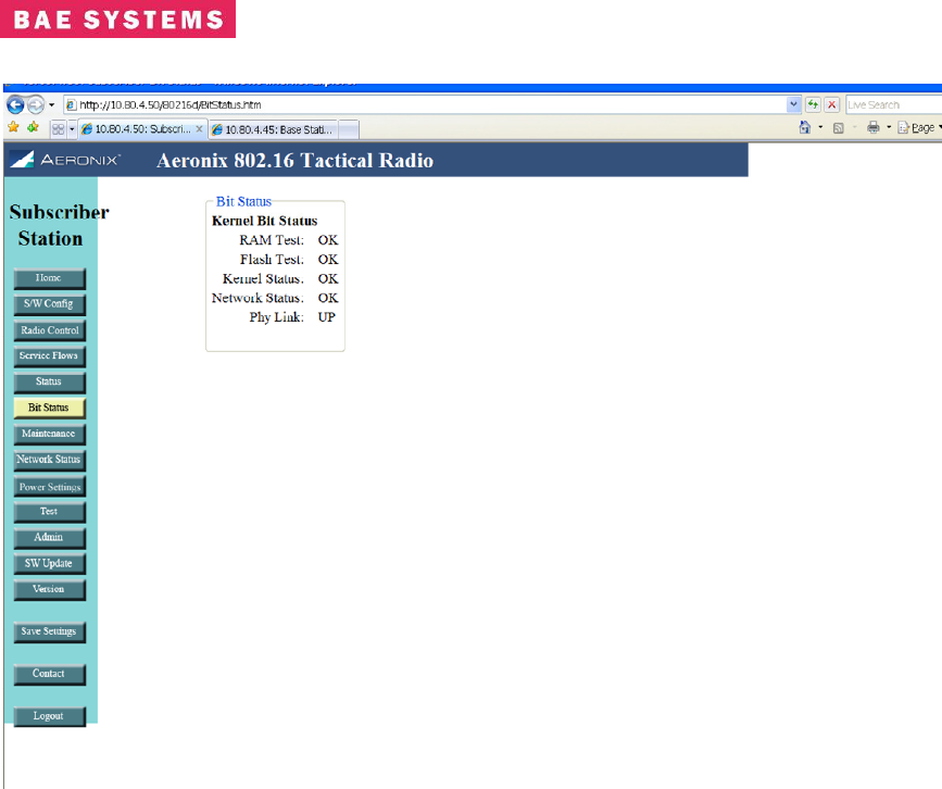
Subscriber Station Bit Status Page
This page shows the results of the bit tests executed at startup. The names and number of tests
may change due to FIPS requirement changes.
Revision: I
CAGE Code: 0D0D0
ITAR CONTROLLED
55
BAE SYSTEMS PROPRIETARY INFORMATION
Use or disclosure of data contained on this sheet
is subject to the restriction on the title page.
Revision: I
CAGE Code: 0D0D0
ITAR CONTROLLED
56
BAE SYSTEMS PROPRIETARY INFORMATION
Use or disclosure of data contained on this sheet
is subject to the restriction on the title page.
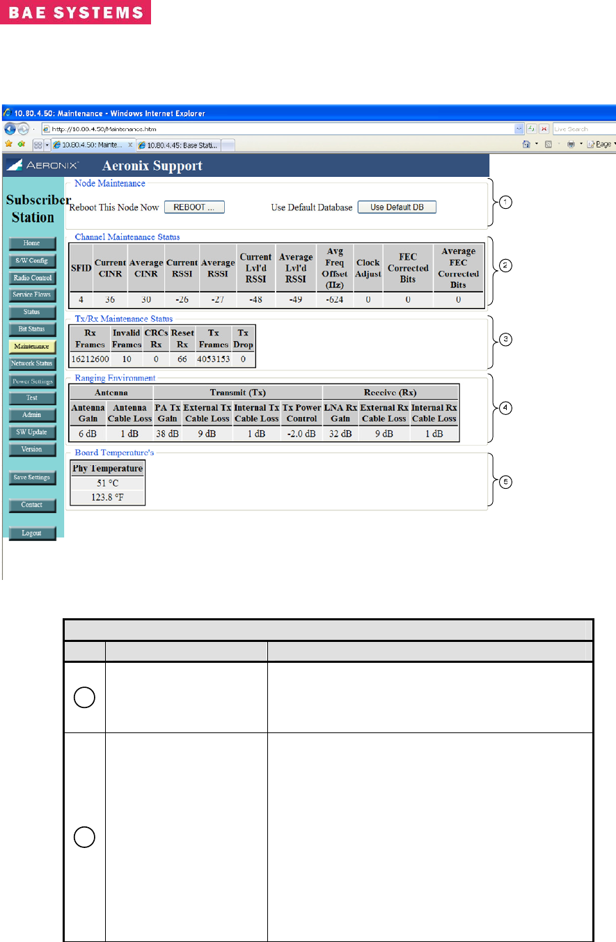
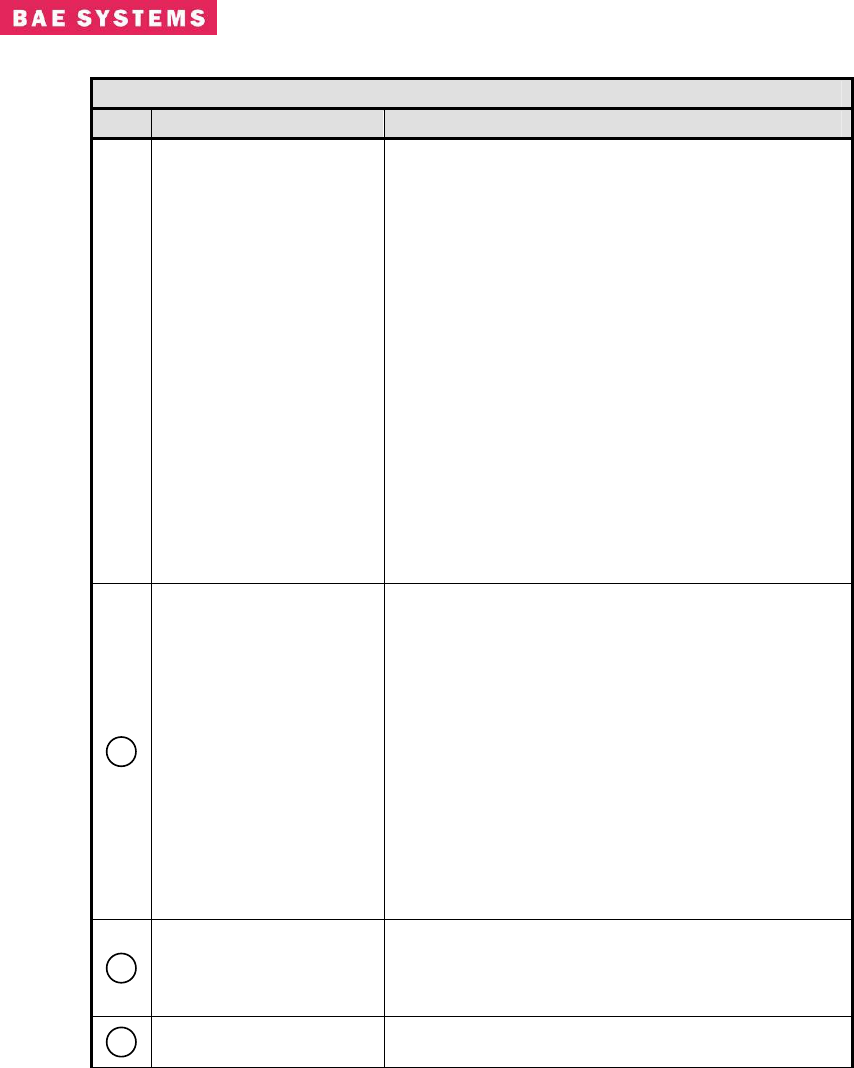
Subscriber Station Maintenance Page
Table 0-21. Subscriber Station Maintenance Page
Field/Control Description
1
Node Maintenance
Provides a method of rebooting the system
without a power cycle.
Provides a method to revert back to the default
database.
2
Channel Maintenance
Status
Provides some additional values on a connection
basis for debugging and antenna pointing
purposes.
• Current CINR – the instantaneous CINR
for the connection.
• Average CINR – the average CINR of the
connection over a period of received
frames.
• Current RSSI – the instantaneous RSSI
for the connection.
• Average RSSI – the average RSSI of the
connection over a period of received
Revision: I
CAGE Code: 0D0D0
ITAR CONTROLLED
57
BAE SYSTEMS PROPRIETARY INFORMATION
Use or disclosure of data contained on this sheet
is subject to the restriction on the title page.
Table 0-21. Subscriber Station Maintenance Page
Field/Control Description
frames.
• Current Leveled RSSI – the current
leveled RSSI value for the connection.
The leveled RSSI reflects the loss and
gain values from the output of the PHY
(including the transmit power attenuation
value) to the PA/LNA.
• Average Leveled RSSI – the average
leveled RSSI value of the connection over
a period of received frames.
• Average Frequency Offset – the average
frequency offset of the connection over a
period of received frames.
• FEC Corrected Bits – the instantaneous
forward error correction corrected bits
• Average FEC Corrected Bits – the
average forward error correction
corrected bits for the connection
3
Tx/Rx Maintenance
Status
Provides the Tx and Rx frame counts and well as
error counts for debugging.
• Rx Frames – the number of frames
received
• Invalid Frames – the number of frames
received that were invalid
• CRCs Rx – the number of CRCs received
• Reset Rx – the number of times the
receive path has been reset
• Tx Frames – the number of frame
transmitted
• Tx Drop – the number of transmit frames
that were dropped by the classifiers
4
Ranging Environment
Provides the gain and loss settings used for
ranging purposes and EIRP calculations. These
settings are configured on the Power Settings and
Radio Control pages.
5
PHY Temperature Provides the temperature of the PHY card inside
of the radio box.
Revision: I
CAGE Code: 0D0D0
ITAR CONTROLLED
58
BAE SYSTEMS PROPRIETARY INFORMATION
Use or disclosure of data contained on this sheet
is subject to the restriction on the title page.
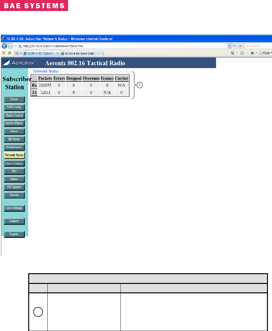
Subscriber Station Network Status Page
Table 0-22. Subscriber Station Network Status
Field/Control Description
1
Network Status
Displays the number of transmitted and received
frames on the network side of the radio. This
reflects the eth0 interface in a non-bridging
configuration and the mybridge interface in a
bridging configuration.
Revision: I
CAGE Code: 0D0D0
ITAR CONTROLLED
59
BAE SYSTEMS PROPRIETARY INFORMATION
Use or disclosure of data contained on this sheet
is subject to the restriction on the title page.
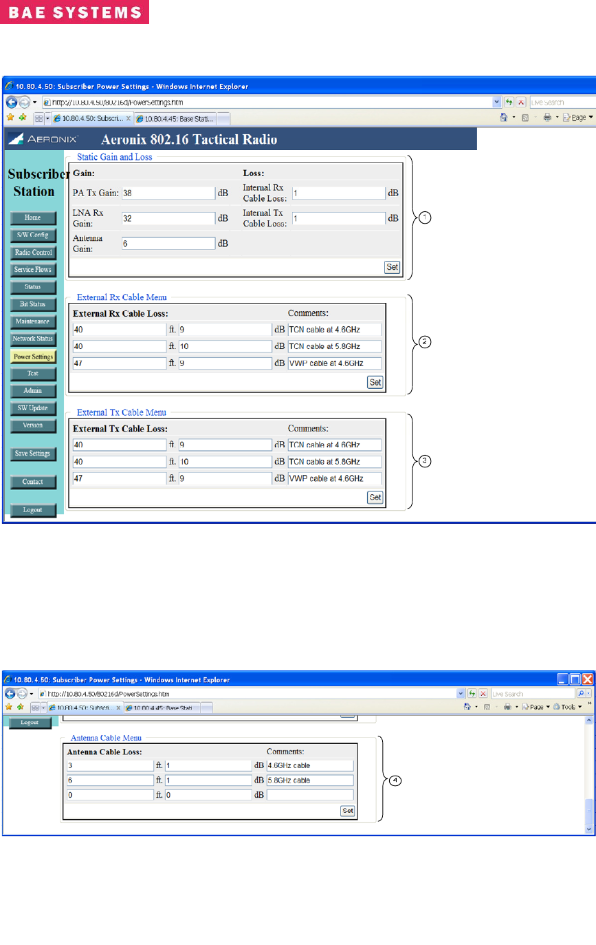
Subscriber Station Power Settings Page

Revision: I
CAGE Code: 0D0D0
ITAR CONTROLLED
60
BAE SYSTEMS PROPRIETARY INFORMATION
Use or disclosure of data contained on this sheet
is subject to the restriction on the title page.
Table 0-23. Subscriber Station Power Settings Page
Field/Control Description
1
Static Gain and Loss
• PA Tx Gain – the transmit gain of the
power amplifier located outside of the
radio
• LNA Rx Gain – the receive gain of the low
noise amplifier located outside of the
radio
• Antenna Gain – the gain of the antenna
located outside of the radio
• Internal Rx Cable Loss - the loss of the
cable and any other components in the
receive path inside of the radio box but
external to the PHY
• Internal Tx Cable Loss – the loss of the
cable and any other components in the
transmit path inside of the radio box but
external to the PHY
• Attenuation – the change in transmit
power of the PHY
2
External Rx Cable
Menu
• Contains up to three entries for external
receive cable loss values. This value
represents the receive cable between the
radio unit and the receive LNA. The user
inputs the length of the cable in feet and
the loss value in dB. The comment field
is optional. The first value entered will be
the default value that gets used initially for
ranging, leveled RSSI and EIRP
calculations. To change the values used
go to the Radio Control page.
3
External Tx Cable
Menu
• Contains up to three entries for the
transmit cable loss values. This value
represents the cable between the radio
unit and the transmit power amplifier. The
user inputs the length of the cable in feet
and the loss value in dB. The comment
field is optional.
4
Antenna Cable Menu
• Contains up to three entries for the
antenna cable loss values. This value
represents the cable between the power
head and the antenna. The user inputs
the length of the cable in feet and the loss
value in dB. The comment field is
optional.
Notes:
The Set button in each section is used to place the current values entered into the
database.
Revision: I
CAGE Code: 0D0D0
ITAR CONTROLLED
61
BAE SYSTEMS PROPRIETARY INFORMATION
Use or disclosure of data contained on this sheet
is subject to the restriction on the title page.
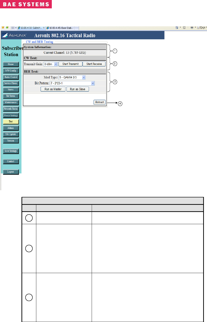
Subscriber Station Test Page
Table 0-24. Subscriber Station Test Page
Field/Control Description
1
System Information Provides the current channel information of the
radio
2
CW Test
Provides the capability to execute a continuous
waveform test.
• Transmit Gain – Selection of the transmit
gain desired from the pull down menu.
• Start Transmit – Starts the transmission of
a CW
• Start Receive – Starts the receive of a
CW
3
BER Test
Provides the capability to execute a bit error rate
test.
• Mod Type – Defines the modulation type
used during the test.
• Bit Pattern – Define the bit patter used
during the test.
• Run as Master – Starts the test with the
radio as the master.
Revision: I
CAGE Code: 0D0D0
ITAR CONTROLLED
62
BAE SYSTEMS PROPRIETARY INFORMATION
Use or disclosure of data contained on this sheet
is subject to the restriction on the title page.
Table 0-24. Subscriber Station Test Page
Field/Control Description
• Run as Slave – Starts the test with the
radio as the slave.
4
Control Buttons • Reboot – reboots the system.
Notes:
Executing any of the tests from this page requires a reboot of the system to return the
radio to normal operation.
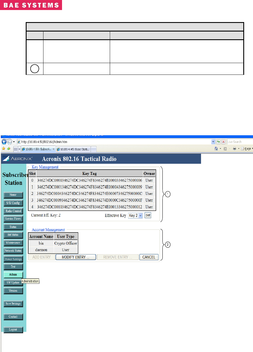
Subscriber Admin Page
Revision: I
CAGE Code: 0D0D0
ITAR CONTROLLED
63
BAE SYSTEMS PROPRIETARY INFORMATION
Use or disclosure of data contained on this sheet
is subject to the restriction on the title page.
Table 0-25. Subscriber Station Admin Page
Field/Control Description
1
Key Management
Provides the crypto user with the capability to
choose the active key slot by selecting the slot
from the drop down menu and clicking the set
button.
2
Account Management Provides each user with the capability to change
account passwords.
Subscriber Software Update Page
Table 0-26. Subscriber Station Software Update Page
Field/Control Description
1
Software Update
Provides the crypto user with the capability to
choose to update the software on the unit.
• File Path – location of the file to update on
the unit.
• Update type – the type of file on the unit
to update.
Revision: I
CAGE Code: 0D0D0
ITAR CONTROLLED
64
BAE SYSTEMS PROPRIETARY INFORMATION
Use or disclosure of data contained on this sheet
is subject to the restriction on the title page.
Table 0-26. Subscriber Station Software Update Page
Field/Control Description
• Start update button – initiates the update
process
Subscriber Station Version Page
Table 0-27. Subscriber Station Version Page
Field/Control Description
1
GUI Software
Information Date and Time of current GUI build
2
Server IP Address Ethernet IP Address of Base Station
3
Internal IP Address MAC S/W network interface IP Address
4
MAC Address MAC H/W Address of SS network interface
5
MAC CVS Tag SS MAC S/W current version
6
BS MAC Dates SS MAC modules build date and time
Revision: I
CAGE Code: 0D0D0
ITAR CONTROLLED
65
BAE SYSTEMS PROPRIETARY INFORMATION
Use or disclosure of data contained on this sheet
is subject to the restriction on the title page.
Table 0-27. Subscriber Station Version Page
Field/Control Description
7
Phy Versions Firmware versions for PHY and Serial Number of
PHY
Contact Page
The contact page provides contact information for the 802.16 product.
Revision: I
CAGE Code: 0D0D0
ITAR CONTROLLED
66
BAE SYSTEMS PROPRIETARY INFORMATION
Use or disclosure of data contained on this sheet
is subject to the restriction on the title page.
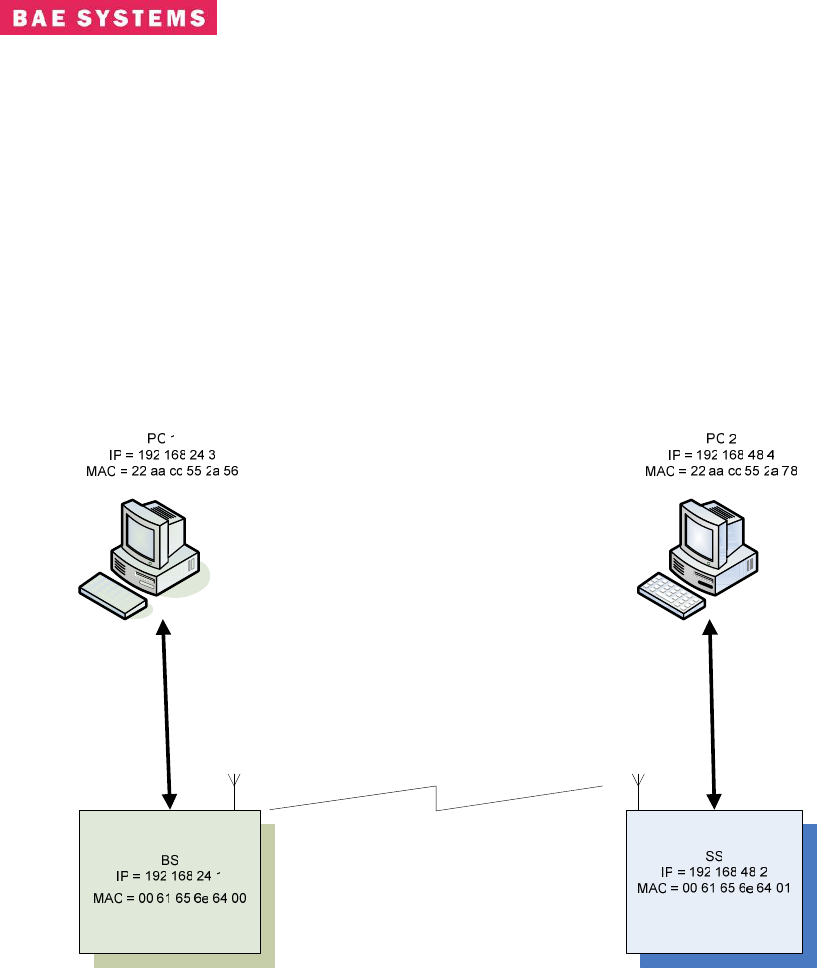
5.0 SYSTEM SETUP AND CONFIGURATION EXAMPLE
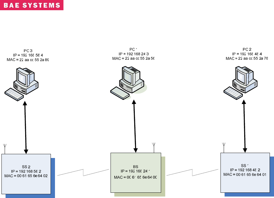
5.1 Bridging Mode Scenario
Setup a simple BS – SS Bridging configuration with one external network node on the SS and on
external node on the BS. For a user scenario you should substitute users’ addresses for BS, SS,
PC1, and PC2.
In the bridging mode, use of internal MAC addresses is required. For the current radios the BS
MAC is 00:61:65:6e:64:00 and SS MAC is 00:61:65:6e:64:nn where nn equals the subscriber
number configured in the start script.
Figure 13. Example Bridging Setup Scenario
5.2 Bridging Base Station Configuration Mode
1) Turn AER16 Power ON.
2) Connect to AER16 Users Port with terminal emulator. (Baud = 115200, 8-N-1 no flow
control)
3) $ cd /mnt/jffs2
4) $ cp startShimBridgeBS start
5) $ vi start
a. Change ifconfig line to use desired IP address“192.168.24.1”
b. Save file.

Revision: I
CAGE Code: 0D0D0
ITAR CONTROLLED
67
BAE SYSTEMS PROPRIETARY INFORMATION
Use or disclosure of data contained on this sheet
is subject to the restriction on the title page.
6) If you have upgraded to a release of code that has database changes, now is the time to
remove your old databases. Please refer to the release notes of each release to determine
if a remove of the database is necessary.
rm /mnt/jffs2/database/*
7) Open shell to radio and execute “reboot” to reboot the radio. < reboot the machine or
cycle power>
8) From PC 1, bring up Internet Explorer.
9) In Internet explorer, put the following in the address field:
a. http://192.168.24.1
10) Follow the <S/W Config> link to the configuration page.
11) Configure a Service Class: A few default service classes are configured automatically.
One of these may be sufficient for your needs and this step can be skipped.
a. Schedule Type = Best Effort, Latency = 80, Jitter = 20, Priority = 1
b. SC 1: (Name = “Gold”, Max Rate = 50,000 Kbps, Min Rate = 1,000 Kbps)
12) Now configure 2 Provisioned Service Flows (upstream and downstream) for the PCs and
specify the desired bandwidth by choosing the appropriate service class. In bridging
mode the MAC addresses in the service flows should be the one of the subscriber station.
One can remove any existing service flows that are not being used prior to configuring
additional ones.
a. SF 1: (SF Index = 4, MAC= 00 61 65 6e 64 01, Direction=Upstream, Service
Class = Gold, State = Provisioned)
b. SF 2: (SF Index = 5, MAC= 00 61 65 6e 64 01, Direction=Downstream, Service
Class = Gold, State = Provisioned)
13) Remove any existing classifiers then configure the classifiers. The classifiers allow data
to flow through the system across the specified service flows. Shown below are the
classifiers for the upstream and downstream service flows configured previously. This
example shows the configuration of classifiers using MAC addresses. The SF Index must
match the SF Index of the corresponding service flow.
a. Class 1: (SF Index = 4, Src Mac = 22 aa cc 55 2a 78, Dst Mac = 22 aa cc 55 2a
56, Src Mask = ff ff ff ff ff ff, Dst Mask = ff ff ff ff ff ff)
b. Class 2: (SF Index = 5, Src Mac = 22 aa cc 55 2a 56, Dst Mac = 22 aa cc 55 2a
78, Src Mask = ff ff ff ff ff ff, Dst Mask = ff ff ff ff ff ff)
14) Follow the <Radio Control> Link.
15) Select the desired channel from the Channel (Freq) drop down menu. One should select a
frequency that is in the same band as power head being used.
16) Click the Set button next to the drop down.
17) Set Tx/Rx to ON if it is not.
18) Configure the Tx gain and hit the corresponding set button.
19) Enable or disable TRANSEC.
20) If TRANSEC is enabled, enter the KEY and hit the corresponding Load Now button or
make no changes and run with the default key.

Revision: I
CAGE Code: 0D0D0
ITAR CONTROLLED
68
BAE SYSTEMS PROPRIETARY INFORMATION
Use or disclosure of data contained on this sheet
is subject to the restriction on the title page.
21) Click the Save Settings button to save the newly selected values to the database.
22) Proceed to SS configuration.

Revision: I
CAGE Code: 0D0D0
ITAR CONTROLLED
69
BAE SYSTEMS PROPRIETARY INFORMATION
Use or disclosure of data contained on this sheet
is subject to the restriction on the title page.
5.3 Bridging Subscriber Station Configuration Mode
1. Turn Power ON.
2. Connect to Users Port with terminal emulator. (Baud = 115200, 8-N-1 no flow control)
3. $ cp startShimBridgeSS start
4. $ cd /mnt/jffs2
5. $ vi start
a. Change ifconfig line to use desired IP address“192.168.24.2”
b. Change this line ‘insmod macss.ko subscriberNumber=1’ to = the desired
subscriber number
c. Save file.
6. If you have upgraded to a release of code that has database changes, now is the time to
remove you old databases. Please refer to the release notes of each release to determine
if a remove of the database is necessary. If removal is necessary, type:
rm /mnt/jffs2/database/*
7. Reboot the unit by typing “reboot” at the console prompt or power cycle the unit.
8. From PC 2, bring up an Internet browser. Make sure you have configured the PC
network parameters.
9. In the browser, put the following in the address field:
a. http://192.168.24.2
10. Follow the <Radio Control> Link.
11. Select the desired channel from the Channel (Freq) drop down menu. The channel
should match that of the base station.
12. Set Tx/Rx to ON.
13. Enable or disable TRANSEC to match the selection of the base station.
14. If TRANSEC is enabled, enter the KEY and hit the corresponding Load Now button or
make no changes and run with the default key.
15. Click the Save Settings button to save the newly selected values to the database
Revision: I
CAGE Code: 0D0D0
ITAR CONTROLLED
70
BAE SYSTEMS PROPRIETARY INFORMATION
Use or disclosure of data contained on this sheet
is subject to the restriction on the title page.
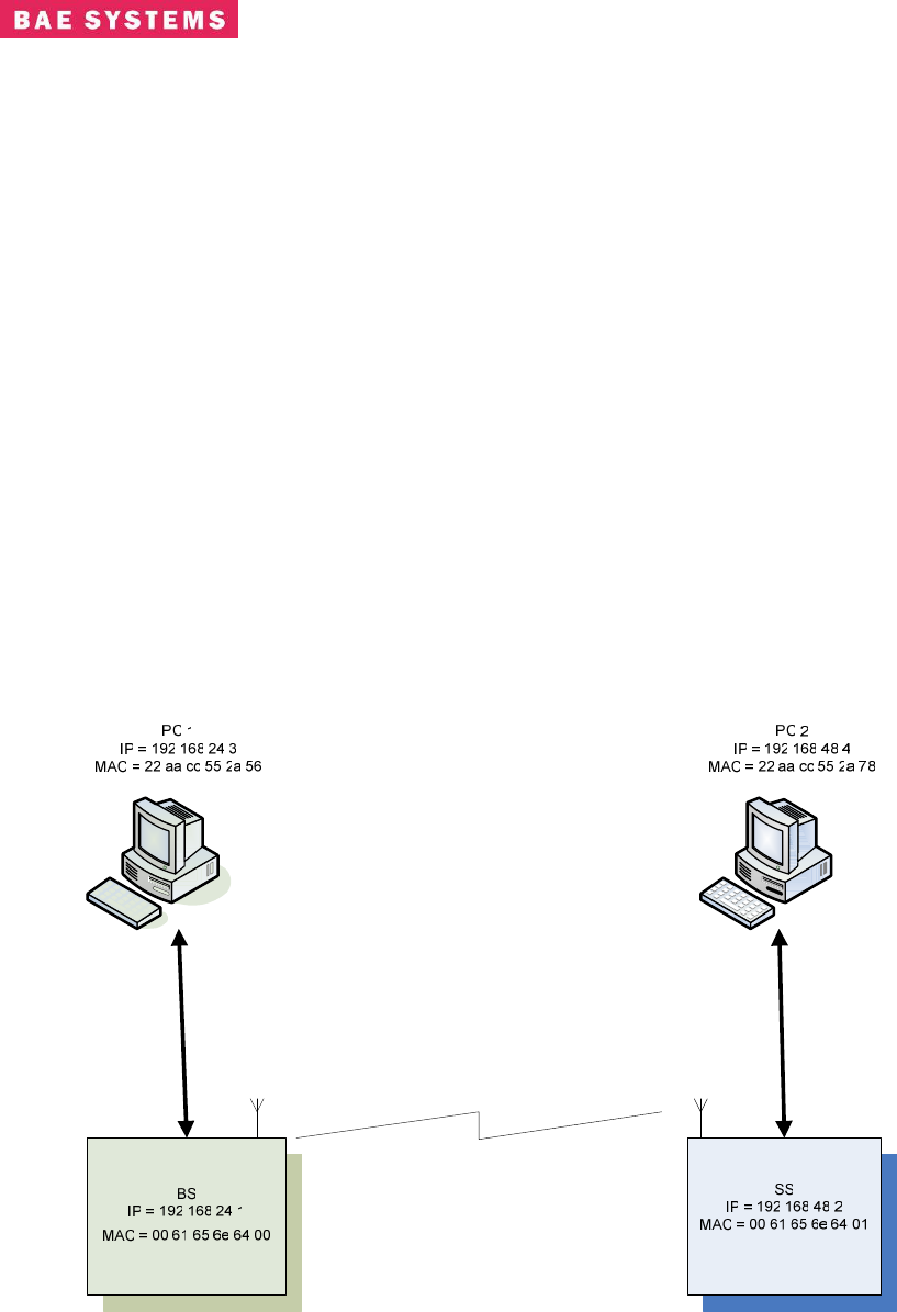
5.3.1 Bridging Base Station Configuration Mode with two subscribers
Figure 13.1 Example Bridging Setup Scenario 2 subscribers
1) Turn AER16 Power ON.
2) Connect to AER16 Users Port with terminal emulator. (Baud = 115200, 8-N-1 no flow
control)
3) $ cd /mnt/jffs2
4) $ cp startShimBridgeBS start
5) $ vi start
a. Change ifconfig line to use desired IP address“192.168.24.1”
b. Save file.
6) If you have upgraded to a release of code that has database changes, now is the time to
remove your old databases. Please refer to the release notes of each release to determine
if a remove of the database is necessary.
rm /mnt/jffs2/database/*
7) Open shell to radio and execute “reboot” to reboot the radio. < reboot the machine or
cycle power>
8) From PC 1, bring up Internet Explorer.
9) In Internet explorer, put the following in the address field:
a. http://192.168.24.1
10) Follow the <S/W Config> link to the configuration page.

Revision: I
CAGE Code: 0D0D0
ITAR CONTROLLED
71
BAE SYSTEMS PROPRIETARY INFORMATION
Use or disclosure of data contained on this sheet
is subject to the restriction on the title page.
11) Configure a Service Class: A few default service classes are configured automatically.
One of these may be sufficient for your needs and this step can be skipped.
a. Schedule Type = Best Effort, Latency = 80, Jitter = 20, Priority = 1
b. SC 1: (Name = “Gold”, Max Rate = 50,000 Kbps, Min Rate = 1,000 Kbps)
12) Now configure 2 Provisioned Service Flows (upstream and downstream) for the PCs and
specify the desired bandwidth by choosing the appropriate service class. In bridging
mode the MAC addresses in the service flows should be the one of the subscriber station.
One can remove any existing service flows that are not being used prior to configuring
additional ones.
a. SF 1: (SF Index = 4, MAC= 00 61 65 6e 64 01, Direction=Upstream, Service
Class = Gold, State = Provisioned)
b. SF 2: (SF Index = 5, MAC= 00 61 65 6e 64 01, Direction=Downstream, Service
Class = Gold, State = Provisioned)
c. SF 1: (SF Index = 6, MAC= 00 61 65 6e 64 02, Direction=Upstream, Service
Class = Gold, State = Provisioned)
d. SF 2: (SF Index = 7, MAC= 00 61 65 6e 64 02, Direction=Downstream, Service
Class = Gold, State = Provisioned)
13) Remove any existing classifiers then configure the classifiers. The classifiers allow data
to flow through the system across the specified service flows. Shown below are the
classifiers for the upstream and downstream service flows configured previously. This
example shows the configuration of classifiers using MAC addresses. The SF Index must
match the SF Index of the corresponding service flow.
a. Class 1: (SF Index = 4, Src Mac = 22 aa cc 55 2a 78, Dst Mac = 22 aa cc 55 2a
56, Src Mask = ff ff ff ff ff ff, Dst Mask = ff ff ff ff ff ff)
b. Class 2: (SF Index = 5, Src Mac = 22 aa cc 55 2a 56, Dst Mac = 22 aa cc 55 2a
78, Src Mask = ff ff ff ff ff ff, Dst Mask = ff ff ff ff ff ff)
c. Class 3: (SF Index = 6, Src Mac = 22 aa cc 55 2a 89, Dst Mac = 22 aa cc 55 2a
56, Src Mask = ff ff ff ff ff ff, Dst Mask = ff ff ff ff ff ff)
d. Class 4: (SF Index = 7, Src Mac = 22 aa cc 55 2a 56, Dst Mac = 22 aa cc 55 2a
89, Src Mask = ff ff ff ff ff ff, Dst Mask = ff ff ff ff ff ff)
e. Class 5: (SF Index = 4, Src Mac = 22 aa cc 55 2a 78, Dst Mac = 22 aa cc 55 2a
89, Src Mask = ff ff ff ff ff ff, Dst Mask = ff ff ff ff ff ff)
f. Class 6: Check forward flag (SF Index = 5, Src Mac = 22 aa cc 55 2a 89, Dst Mac
= 22 aa cc 55 2a 78, Src Mask = ff ff ff ff ff ff, Dst Mask = ff ff ff ff ff ff)
g. Class 7: (SF Index = 6, Src Mac = 22 aa cc 55 2a 89, Dst Mac = 22 aa cc 55 2a
78, Src Mask = ff ff ff ff ff ff, Dst Mask = ff ff ff ff ff ff)
h. Class 8: Check forward flag (SF Index = 7, Src Mac = 22 aa cc 55 2a 78, Dst Mac
= 22 aa cc 55 2a 89, Src Mask = ff ff ff ff ff ff, Dst Mask = ff ff ff ff ff ff)
14) Follow the <Radio Control> Link.
15) Select the desired channel from the Channel (Freq) drop down menu. One should select a
frequency that is in the same band as power head being used.
16) Click the Set button next to the drop down.
Revision: I
CAGE Code: 0D0D0
ITAR CONTROLLED
72
BAE SYSTEMS PROPRIETARY INFORMATION
Use or disclosure of data contained on this sheet
is subject to the restriction on the title page.
17) Set Tx/Rx to ON if it is not.
18) Configure the Tx gain and hit the corresponding set button.
19) Enable or disable TRANSEC.
20) If TRANSEC is enabled, enter the KEY and hit the corresponding Load Now button or
make no changes and run with the default key.
21) Click the Save Settings button to save the newly selected values to the database.
22) Proceed to SS configuration.
5.4 Non-Bridging Mode Scenario
Setup a simple BS – SS non-bridging configuration with one external network node on the SS
and on external node on the BS. For a user scenario you should substitute user’s addresses for
BS, SS, PC1, and PC2.
In the non-bridging mode, use of internal MAC addresses is required. For the current radios the
BS MAC is 00:61:65:6e:64:00 and SS MAC is 00:61:65:6e:64:nn where nn equals the subscriber
number configured in the start script.
Figure 14. Example Non-Bridging Setup Scenario

Revision: I
CAGE Code: 0D0D0
ITAR CONTROLLED
73
BAE SYSTEMS PROPRIETARY INFORMATION
Use or disclosure of data contained on this sheet
is subject to the restriction on the title page.
5.5 Non-Bridging Base Station Configuration Mode
1. Turn AER16 Power ON.
2. Connect to AER16 Users Port with terminal emulator. (Baud = 115200, 8-N-1 no flow
control)
3. $ cd /mnt/jffs2
4. $ cp startShimBS start
5. $ vi start
a. Change ‘ifconfig eth0’ line to use desired IP address“192.168.24.1”
b. Modify the “route add” line to have the appropriate -net address. For the net
address use “192.168.48.0”.
c. Save file.
6. If you have upgraded to a release of code that has database changes, now is the time to
remove you old databases. Please refer to the release notes of each release to determine
if a removal of the database is necessary. If removal is necessary, type:
rm /mnt/jffs2/database/*
7. Reboot the unit by typing “reboot” at the console prompt or power cycle the unit.
8. From PC 1, bring up an Internet browser. Make sure you have configured the PC
network parameters.
9. In the browser, put the following in the address field:
a. http://192.168.24.1
10. Follow the <S/W Config> link to the configuration page.
11. Configure a Service Class: A few default service classes are configured automatically.
One of these may be sufficient for your needs and this step can be skipped.
a. Schedule Type = Best Effort, latency = 80, Jitter = 20, Priority = 1
b. SC 1: (Name = “Gold”, Max Rate = 50,000 Kbps, Min Rate = 1,000 Kbps)
12. Now configure 2 Provisioned Service Flows (upstream and downstream) for the PCs and
specify the desired bandwidth by choosing the appropriate service class if they do not
already exist. To display the MAC address of the radio, open a shell and execute
“ifconfig | more”.
a. SF 1: (SF Index = 4, MAC= 00 61 65 6e 64 01, Direction=Upstream, Service
Class = Gold, State = Provisioned)
b. SF 2: (SF Index = 5, MAC= 00 61 65 6e 64 01, Direction=Downstream, Service
Class = Gold, State = Provisioned)
13. Remove any existing classifiers that are not needed and then configure the classifiers.
Classifiers allow data to flow through the system across the specified service flows.
Below are the classifiers for the upstream and downstream service flows configured using
MAC addresses. The SF Index must match the SF Index of the corresponding service
flow.
a. Class 1: (SF Index = 4, Src Mac = 00 61 65 6e 64 01, Dst Mac = 00 61 65 6e 64
00, Src Mask = ff ff ff ff ff ff, Dst Mask = ff ff ff ff ff ff)

Revision: I
CAGE Code: 0D0D0
ITAR CONTROLLED
74
BAE SYSTEMS PROPRIETARY INFORMATION
Use or disclosure of data contained on this sheet
is subject to the restriction on the title page.
b. Class 2: (SF Index = 5, Src Mac = 00 61 65 6e 64 00, Dst Mac = 00 61 65 6e 64
01, Src Mask = ff ff ff ff ff ff, Dst Mask = ff ff ff ff ff ff)
14. Follow the <Radio Control> Link.
15. Select the desired channel from the Channel (Freq) drop down menu.
16. Click the Set button next to the drop down.
17. Set Tx/Rx to ON if it is not.
18. Configure the max distance for SS acquisition.
19. Click the set button in the ranging environment section of the Radio Control screen.
20. Enable or disable TRANSEC.
21. If TRANSEC is enabled, enter the KEY and hit the corresponding Load Now button or
make no changes and run with the default key.
22. Click the Save Settings button to save the newly selected values to the database.
23. Proceed to SS configuration.

Revision: I
CAGE Code: 0D0D0
ITAR CONTROLLED
75
BAE SYSTEMS PROPRIETARY INFORMATION
Use or disclosure of data contained on this sheet
is subject to the restriction on the title page.
5.6 Non-Bridging Subscriber Station Configuration Mode
1. Turn Power ON.
2. Connect to Users Port with terminal emulator. (Baud = 115200, 8-N-1 no flow control)
3. $ cd /mnt/jffs2
4. $ cp startShimSS start
5. vi start
a. Change ‘ifconfig eth0’ line to use desired IP address“192.168.48.2”
b. Change this line ‘insmod macss.ko subscriberNumber=1’ to = the desired
subscriber number. If multiple subscribers increase number accordingly.
c. Modify the “route add” line to have the appropriate -net address. For the net
address use “192.168.24.0”.
d. Save the file.
6. If you have upgraded to a release of code that has database changes, now is the time to
remove you old databases. Please refer to the release notes of each release to determine
if a remove of the database is necessary. If removal is necessary, type:
rm /mnt/jffs2/database/*
7. Reboot the unit by typing “reboot” at the console prompt or power cycle the unit.
8. From PC 2, bring up an Internet browser. Make sure you have configured the PC
network parameters.
9. In the browser, put the following in the address field:
a. http://192.168.48.2
10. Follow the <Radio Control> Link.
11. Select the desired channel from the Channel (Freq) drop down menu. The channel
should match that of the base station.
12. Set Tx/Rx to ON.
13. Enable or disable TRANSEC to match the selection of the base station.
14. If TRANSEC is enabled, enter the KEY and hit the corresponding Load Now button or
make no changes and run with the default key.
15. Click the Save Settings button to save the newly selected values to the database.
Revision: I
CAGE Code: 0D0D0
ITAR CONTROLLED
76
BAE SYSTEMS PROPRIETARY INFORMATION
Use or disclosure of data contained on this sheet
is subject to the restriction on the title page.
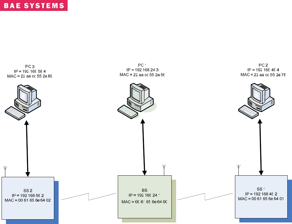
5.6.1 Non-Bridging Base Station Configuration Mode with Two subscribers
Figure 14.1 Non –Bridging Example with 2 Subscribers
1. Turn AER16 Power ON.
2. Connect to AER16 Users Port with terminal emulator. (Baud = 115200, 8-N-1 no flow
control)
3. $ cd /mnt/jffs2
4. $ cp startShimBS start
5. $ vi start
a. Change ‘ifconfig eth0’ line to use desired IP address“192.168.24.1”
b. Modify the “route add” line to have the appropriate -net address. For the net
address use “192.168.48.0”.
c. Save file.
6. If you have upgraded to a release of code that has database changes, now is the time to
remove you old databases. Please refer to the release notes of each release to determine
if a removal of the database is necessary. If removal is necessary, type:
rm /mnt/jffs2/database/*
7. Reboot the unit by typing “reboot” at the console prompt or power cycle the unit.
8. From PC 1, bring up an Internet browser. Make sure you have configured the PC
network parameters.
9. In the browser, put the following in the address field:

Revision: I
CAGE Code: 0D0D0
ITAR CONTROLLED
77
BAE SYSTEMS PROPRIETARY INFORMATION
Use or disclosure of data contained on this sheet
is subject to the restriction on the title page.
a. http://192.168.24.1
10. Follow the <S/W Config> link to the configuration page.
11. Configure a Service Class: A few default service classes are configured automatically.
One of these may be sufficient for your needs and this step can be skipped.
1) Schedule Type = Best Effort, latency = 80, Jitter = 20, Priority = 1
2) SC 1: (Name = “Gold”, Max Rate = 50,000 Kbps, Min Rate = 1,000 Kbps)
12. Now configure 2 Provisioned Service Flows (upstream and downstream) for the PCs and
specify the desired bandwidth by choosing the appropriate service class if they do not
already exist. To display the MAC address of the radio, open a shell and execute
“ifconfig | more”.
a. SF 1: (SF Index = 4, MAC= 00 61 65 6e 64 01, Direction=Upstream, Service
Class = Gold, State = Provisioned)
b. SF 2: (SF Index = 5, MAC= 00 61 65 6e 64 01, Direction=Downstream, Service
Class = Gold, State = Provisioned)
c. SF 1: (SF Index = 6, MAC= 00 61 65 6e 64 02, Direction=Upstream, Service
Class = Gold, State = Provisioned)
d. SF 2: (SF Index = 7, MAC= 00 61 65 6e 64 02, Direction=Downstream, Service
Class = Gold, State = Provisioned)
13. Remove any existing classifiers that are not needed and then configure the classifiers.
Classifiers allow data to flow through the system across the specified service flows.
Below are the classifiers for the upstream and downstream service flows configured using
MAC addresses. The SF Index must match the SF Index of the corresponding service
flow.
a. Class 1: (SF Index = 4, Src Mac = 00 61 65 6e 64 01, Dst Mac = 00 61 65 6e 64
00, Src Mask = ff ff ff ff ff ff, Dst Mask = ff ff ff ff ff ff)
b. Class 2: (SF Index = 5, Src Mac = 00 61 65 6e 64 00, Dst Mac = 00 61 65 6e 64
01, Src Mask = ff ff ff ff ff ff, Dst Mask = ff ff ff ff ff ff)
c. Class 3: (SF Index = 6, Src Mac = 00 61 65 6e 64 02, Dst Mac = 00 61 65 6e 64
00, Src Mask = ff ff ff ff ff ff, Dst Mask = ff ff ff ff ff ff)
d. Class 4: (SF Index = 7, Src Mac = 00 61 65 6e 64 00, Dst Mac = 00 61 65 6e 64
02, Src Mask = ff ff ff ff ff ff, Dst Mask = ff ff ff ff ff ff)
e. Class 5: (SF Index = 4, Src Mac = 00 61 65 6e 64 01, Dst Mac = 00 61 65 6e 64
02, Src Mask = ff ff ff ff ff ff, Dst Mask = ff ff ff ff ff ff)
f. Class 6: Check forward flag (SF Index = 5, Src Mac = 00 61 65 6e 64 02, Dst
Mac = 00 61 65 6e 64 01, Src Mask = ff ff ff ff ff ff, Dst Mask = ff ff ff ff ff ff)
g. Class 5: (SF Index = 6, Src Mac = 00 61 65 6e 64 02, Dst Mac = 00 61 65 6e 64
01, Src Mask = ff ff ff ff ff ff, Dst Mask = ff ff ff ff ff ff)
h. Class 6: Check forward flag (SF Index = 7, Src Mac = 00 61 65 6e 64 01, Dst
Mac = 00 61 65 6e 64 02, Src Mask = ff ff ff ff ff ff, Dst Mask = ff ff ff ff ff ff)
14. Follow the <Radio Control> Link.
15. Select the desired channel from the Channel (Freq) drop down menu.
16. Click the Set button next to the drop down.

Revision: I
CAGE Code: 0D0D0
ITAR CONTROLLED
78
BAE SYSTEMS PROPRIETARY INFORMATION
Use or disclosure of data contained on this sheet
is subject to the restriction on the title page.
17. Set Tx/Rx to ON if it is not.
18. Configure the max distance for SS acquisition.
19. Click the set button in the ranging environment section of the Radio Control screen.
20. Enable or disable TRANSEC.
21. If TRANSEC is enabled, enter the KEY and hit the corresponding Load Now button or
make no changes and run with the default key.
22. Click the Save Settings button to save the newly selected values to the database.
23. Proceed to SS configuration.
Revision: I
CAGE Code: 0D0D0
ITAR CONTROLLED
79
BAE SYSTEMS PROPRIETARY INFORMATION
Use or disclosure of data contained on this sheet
is subject to the restriction on the title page.
6.0 PERFORMANCE
Radio Performance
The 802.16 Radio meets or exceeds the performance parameters listed in Table 6-1.
Table 6-1. Modem Performance
Parameter Value Units
Band 1 Channel Center Frequencies 5.745, 5.765, 5.785,
5.805, 5.825 +/- 1 ppm @ 25
°
C GHz
Band 2 Channel Center Frequencies 4.52, 4.54, 4.56, 4.58,
4.6, 4.62, 4.64, 4.66, 4.68
+/- 1.5 ppm -40
°
C to
+70
°
C GHz
Transmitter: 25°C -40°C to +70°C
Average (RMS) Output Power 0 +/-1dB dBm
Peak Output Power +27 +/-1dB 25
°
C value -
3dBm/+1.5dBm dBm
Transmit 1dB Output Compression +37 dBm
VSWR 2:1
Channel Bandwidth 15.6 MHz
LO leakage 15.3 dBm
Receiver:
Input Damage Level 13 dBm
Input 1 dB compression
P
1
P
-7.8 -9.4 to -6.4 dBm
Input 1 dB compression
P
2
P
-6.4 -7.2 to -5.7 dBm
Input Third Order Intercept
P
1
P
3 2 to 4.7 dBm
Input Third Order Intercept
P
2
P
7.8 6.9 to 8.5 dBm
LO leakage -25 dBm
VSWR 2:1
Noise Figure 8 db Max 25
°
C value +/- 1 dB dB
P
1
P
With front end attenuator off
P
2
P
With front end attenuator on
6.1 Receiver Sensitivity
The sensitivity of the 802.16 Modem Module receiver conforms to Section 8.3.11.1 of the IEEE
802.16D5-2004 specification. The receiver Signal to Noise Ratio (SNR) assumptions are listed
in Table 6-2.
Table 6-2. Receiver SNR Assumptions
Modulation Coding Rate Receiver SNR (dB) Receiver Sensitivity
(8dB NF & 5dB IL)
BPSK 1/2 6.4 -85.6 dBm
1/2 9.4 -82.6 dBm
QPSK 3/4 11.2 -80.8 dBm
1/2 16.4 -75.6 dBm
16 QAM 3/4 18.2 -73.8 dBm
2/3 22.7 -69.3 dBm
64 QAM 3/4 24.4 -67.6 dBm
Revision: I
CAGE Code: 0D0D0
ITAR CONTROLLED
80
BAE SYSTEMS PROPRIETARY INFORMATION
Use or disclosure of data contained on this sheet
is subject to the restriction on the title page.
6.2 User Data Rates
The 802.16 Modem Module PHY modulates and de-modulates the data packets as specified in
Table 5-3 . The user throughput for the 10 MHz and 20 MHz bandwidths can be found in Table
Table 6-3. User Data Rates 10 MHz 20 MHz Bandwidth
Modulation
Cyclic
prefix
Uncoded
block
size
(bytes/
symbol)
Coded
block
size
(bytes)
Overall
coding
rate
RS code
CC
code
rate
10MHz
BW
Burst
Data
rate
(Mbs)
20 MHz
BW
Burst
Data
rate
(Mbs)
SNR
Eb/No
BPSK 1/4 4 24 1/6 (12,4,4) 1/2 1 2
BPSK 1/4 12 24 1/2 None 1/2 3 6 6.4
BPSK 1/4 24 24 NA None NA 6 12 11(est)
QPSK 1/4 24 48 1/2 (32,24,4) 2/3 6 12 9.4
QPSK 1/4 36 48 3/4 (40,36,3) 5/6 10 18 11.2
QPSK 1/4 48 48 NA None NA 13 24 14(est)
16-QAM 1/4 48 96 1/2 (64,48,8) 2/3 13 24 16.4
16-QAM 1/4 72 96 3/4 (80,72,4) 5/6 20 36 18.2
16-QAM 1/4 96 96 NA None NA 27 48 19(est)
64-QAM 1/4 96 144 2/3 (108,96,6) 3/4 27 48 22.7
64-QAM 1/8 96 144 2/3 (108,96,6) 3/4 30 53.33 22.7
64-QAM 1/8 108 144 3/4 (120,108,6) 5/6 34 60 24.4
64-QAM 1/16 108 144 3/4 (120,108,6) 5/6 36 63.53 24.4
64-QAM 1/32 108 144 3/4 (120,108,6) 5/6 37 65.45 24.4
64-QAM 1/4 144 144 NA None NA 41 72 25(est)
8PSK 1/4 32 72 8/18 (48,32,8) 2/3 9 16
8PSK 1/4 42 72 7/12 (54,42,6) 3/4 12 21
8PSK 1/4 72 72 NA None NA 20 36
16PSK 1/4 48 96 1/2 (64,48,8) 2/3 13 24
16PSK 1/4 72 96 3/4 (80,72,4) 5/6 20 36
16PSK 1/4 96 96 NA None NA 27 48

Revision: I
CAGE Code: 0D0D0
ITAR CONTROLLED
81
BAE SYSTEMS PROPRIETARY INFORMATION
Use or disclosure of data contained on this sheet
is subject to the restriction on the title page.
1 Node 2 Node 3 Node 4 Node 5 Node 6 Node 7 Node 8 Node 9 - 20 Node
Coded Link Thruput Link Thruput Link Thruput Link Thruput Link Thruput Link Thruput Link Thruput Link Thruput Link Thruput
Modulation
Link Rate
Mb/s
Mb/s
Mb/s
Mb/s
Mb/s
Mb/s
Mb/s
Mb/s
Mb/s
BPSK 1/2 6 Mbps 2.6 2.5 2.5 2.5 2.4 2.4 2.4 2.4 2.3
QPSK 1/2 12 Mbps 5.1 5.0 5.0 4.9 4.9 4.8 4.8 4.7 4.7
QPSK 3/4 18 Mbps 7.6 7.5 7.4 7.4 7.3 7.2 7.1 7.1 7.0
16-QAM 1/2 24 Mbps 10.2 10.1 10.0 9.9 9.8 9.7 9.6 9.5 9.4
16-QAM 3/4 36 Mbps 15.3 15.1 15.0 14.8 14.7 14.5 14.4 14.2 14.1
64-QAM 2/3 48 Mbps 20.4 20.2 20.0 19.8 19.6 19.4 19.2 19.0 18.8
64-QAM 3/4 54 Mbps 23.0 22.7 22.5 22.3 22.0 21.8 21.6 21.3 21.1
8-PSK 1/2 18 Mbps 7.7 7.6 7.5 7.4 7.3 7.3 7.2 7.1 7.0
16-PSK 1/2 24 Mbps 10.2 10.1 10.0 9.9 9.8 9.7 9.6 9.5 9.4
16-PSK 3/4
36 Mbps
15.3
15.1
15.0
14.8
14.7
14.5
14.4
14.2
14.1
Table 5-5 User Throughput for 10 MHZ Channel Bandwidth vs Number of Nodes in the Network
1 Node 2 Node 3 Node 4 Node 5 Node 6 Node 7 Node 8 Node 9 - 20 Nodes
Coded Link Thruput Link Thruput Link Thruput Link Thruput Link Thruput Link Thruput Link Thruput Link Thruput Link Thruput
Modulation
Link Rate
Mb/s
Mb/s
Mb/s
Mb/s
Mb/s
Mb/s
Mb/s
Mb/s
Mb/s
BPSK 1/2 6 Mbps 5.1 5.0 5.0 4.9 4.9 4.8 4.8 4.7 4.7
QPSK 1/2 12 Mbps 10.2 10.1 10.0 9.9 9.8 9.7 9.6 9.5 9.4
QPSK 3/4 18 Mbps 15.2 15.0 14.9 14.7 14.6 14.4 14.3 14.1 14.0
16-QAM 1/2 24 Mbps 20.4 20.2 20.0 19.8 19.6 19.4 19.2 19.0 18.8
16-QAM 3/4 36 Mbps 30.6 30.3 30.0 29.7 29.4 29.1 28.8 28.5 28.2
64-QAM 2/3 48 Mbps 40.8 40.4 40.0 39.6 39.2 38.8 38.4 37.9 37.5
64-QAM 3/4 54 Mbps 45.9 45.4 45.0 44.5 44.1 43.6 43.1 42.7 42.2
8-PSK 1/2 18 Mbps 15.3 15.1 15.0 14.8 14.7 14.5 14.4 14.2 14.1
16-PSK 1/2 24 Mbps 20.4 20.2 20.0 19.8 19.6 19.4 19.2 19.0 18.8
16-PSK 3/4
36 Mbps
30.6
30.3
30.0
29.7
29.4
29.1
28.8
28.5
28.2
Table 5-4 User Throughput for 20 MHZ Channel Bandwidth vs Number of Nodes in the Network

Revision: I
CAGE Code: 0D0D0
ITAR CONTROLLED
82
BAE SYSTEMS PROPRIETARY INFORMATION
Use or disclosure of data contained on this sheet
is subject to the restriction on the title page.
APPENDIX: DEFINITIONS, ACRONYMS, AND ABBREVIATIONS
The section provides the necessary definitions, acronyms, and abbreviations relevant to this
document and necessary in order to understand this document.
U
ACID
U
– ARQ Channel ID
U
ARQ
U
– Automatic Repeat Request
U
ATM
U
– Asynchronous Transfer Mode
U
Authentication
U
– Verification of the source of information
U
BS
U
– Base Station
U
CCV
U
– Clock Comparison Value
U
CDMA
U
– Code Division Multiple Access
U
CID
U
– Connection Identifier
U
CINR
U
– Carrier to Interference and Noise Ratio
U
CS
U
– Convergence Sub-layer
U
DCD
U
– Downlink Channel Descriptor
U
DFS
U
– Dynamic Frequency Selection
U
DIUC
U
– Downlink Interval Usage Code
U
DL
U
– Downlink
U
EIRP
U
– Effective Isotropic Radiated Power
U
GPS
U
– Global Positioning System
U
H-ARQ
U
– Hybrid Automatic Repeat Request
U
HMAC
U
– Hashed Message Authentication Code
U
HW
U
– Hardware
U
Instantiate
U
– Create an entity from an abstraction.
U
Integrity
U
– Verification that the information has not been altered.
U
I/O
U
– Input/Output
U
IP
U
– Internet Protocol
U
JTRS
U
– Joint Tactical Radio System
U
MAC
U
– Media Access Control
U
MSB
U
– Most Significant Bit
U
OFDM
U
– Orthogonal Frequency Division Multiplexing
U
OFDMA
U
– Orthogonal Frequency Division Multiple Access
U
OS
U
– Operating System

Revision: I
CAGE Code: 0D0D0
ITAR CONTROLLED
83
BAE SYSTEMS PROPRIETARY INFORMATION
Use or disclosure of data contained on this sheet
is subject to the restriction on the title page.
U
PDU
U
– Payload Data Unit
U
PHS
U
– Payload Header Suppression
U
PHY
U
– Physical Layer
U
PKM
U
– Privacy Key Management
U
QoS
U
– Quality of Service
U
RSSI
U
– Received Signal Strength Indicator
U
RTG
U
– Receive/Transmit Transition Gap
U
SDU
U
– Service Data Unit
U
SFID
U
– Service Flow ID
U
SS
U
– Subscriber Station
U
SW
U
– Software
U
TCP
U
– Transmission Control Protocol
U
TLV
U
– Type Length Value
U
TRANSEC
U
– Transmission Security
U
TTG
U
– Transmit/Receive Transition Gap
U
UCD
U
– Uplink Channel Descriptor
U
UDP
U
– User Datagram Protocol
U
UIUC
U
– Uplink Interval Usage Code
U
UL
U
- Uplink
U
VLAN
U
– Virtual Local Area Network