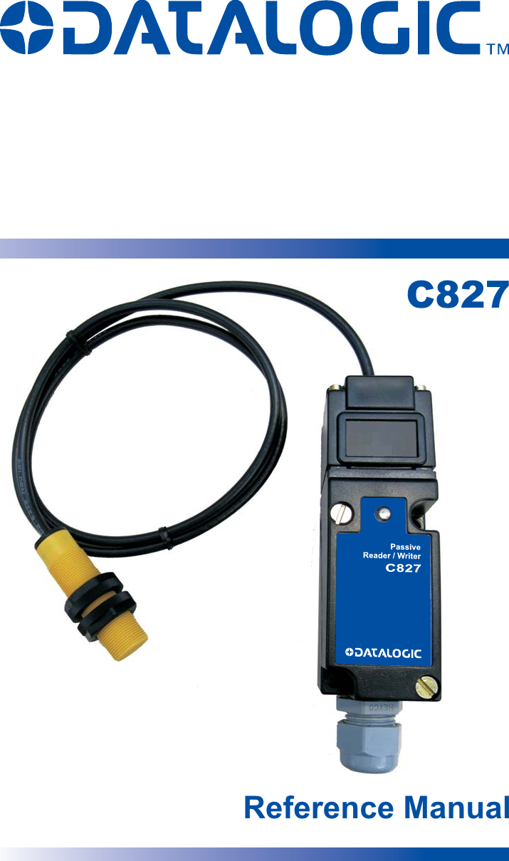
Balluff 0003 HF RFID CONTROLLER User Manual C827 Reference Manual

BALLUFF inc HF RFID CONTROLLER C827 Reference Manual

User Manual

Reference ManualC827
              Datalogic Automation S.r.l. Via Lavino, 256 40050 - Monte S. Pietro Bologna - Italy     C827 Reference Manual  Ed.: 10/2010                © 2010 Datalogic Automation S.r.l.  ALL RIGHTS RESERVED.  Protected to the fullest extent under U.S. and international laws. Copying, or altering of this document is prohibited without express written consent from Datalogic Automation S.r.l.  Datalogic and the Datalogic logo are registered trademarks of Datalogic S.p.A. in many countries, including the U.S.A. and the E.U.  Subnet16, Cobalt Dashboard and Cobalt C-Macro Builder are trademarks of Datalogic Automation S.r.l. All other brand and product names mentioned herein are for identification purposes only and may be trademarks or registered trademarks of their respective owners.  Datalogic shall not be liable for technical or editorial errors or omissions contained herein, nor for incidental or consequential damages resulting from the use of this material.   12/10/10
  iii CONTENTS  REFERENCES ............................................................................................................iv Conventions................................................................................................................. iv Reference Documentation........................................................................................... iv Service and Support .................................................................................................... iv Patents.........................................................................................................................iv COMPLIANCE..............................................................................................................v Radio Compliance ........................................................................................................ v Power Supply................................................................................................................ v FCC Compliance .......................................................................................................... v 1 GETTING STARTED....................................................................................................1 1.1 Introduction...................................................................................................................1 1.2 Unpacking and Inspection ............................................................................................1 1.3 Organization of this Manual..........................................................................................1 2 MECHANICAL SPECIFICATIONS ..............................................................................2 2.1 Dimensions...................................................................................................................2 2.2 C827 Antenna Direction................................................................................................6 2.2.1 Changing the C827 read head orientation....................................................................6 2.2.2 Mounting the C827 .......................................................................................................8 2.2.3 Guidelines.....................................................................................................................8 2.2.4 Mounting HMS Tags to Metal .......................................................................................9 3 POWER AND ELECTRICAL INTERFACE ................................................................10 3.1 Terminal Screws.........................................................................................................10 3.1.1 Power Requirements ..................................................................................................11 3.2 Wiring..........................................................................................................................11 3.3 LED Indicator..............................................................................................................12 4 SERIAL COMMUNICATIONS....................................................................................13 4.1 Overview.....................................................................................................................13 4.2 RS232 Interface..........................................................................................................13 4.3 RS232 Serial Connections..........................................................................................14 4.4 DIP Switches ..............................................................................................................15 4.4.1 RS232 Baud Rate.......................................................................................................16 5 TECHNICAL FEATURES.............................................................................................1
 iv    REFERENCES   CONVENTIONS  This manual uses the following conventions:  "User" refers to anyone using a C827 reader. "Reader" refers to the C827 reader. "You" refers to the System Administrator or Technical Support person using this manual to install, configure, operate, maintain or troubleshoot a C827 reader.    REFERENCE DOCUMENTATION  For further details refer to the Cobalt Dashboard™ Reference Manual, C-Macro Builder™ Reference Manual, and the ABx Command Protocol Reference Manual.    SERVICE AND SUPPORT   Datalogic provides several services as well as technical support through its website. Log on to www.automation.datalogic.com and click on the links indicated for further information:   PRODUCTS Search through the links to arrive at your product page which describes specific Info, Features, Applications, Models, Accessories, and Downloads including the Cobalt Dashboard™ utility program, which allows system testing, monitoring, and configuration using a PC. It provides Serial RS232 interface configuration.   SERVICE - Overview - Warranty Extensions and Maintenance Agreements - Sales Network - Listing of Subsidiaries,Repair Centers,Partners - Helpdesk -  Material Return Authorization   PATENTS  This product is covered by one or more of the following patents:  US 5,621,199; JP 3,728,699.
  v COMPLIANCE   This product is intended to be installed by Qualified Personnel only. This product must not be used in explosive environments.    RADIO COMPLIANCE  ENGLISH Contact the competent authority responsible for the management of radio frequency devices of your country to verify any possible restrictions or licenses required. For further information, refer to the web site: http://ec.europa.eu/enterprise/sectors/rtte/  ITALIANO Prendi contatto con l'autorità competente per la gestione degli apparati a radio frequenza del tuo paese, per verificare eventuali restrizioni o licenze. Ulteriori informazioni sono disponibili sul sito:  http://ec.europa.eu/enterprise/sectors/rtte/  FRANÇAIS Contactez l'autorité compétente en la gestion des appareils à radio fréquence de votre pays pour vérifier d'éventuelles restrictions ou licences. Pour tout renseignement vous pouvez vous adresser au site web: http://ec.europa.eu/enterprise/sectors/rtte/  DEUTSCH Wenden Sie sich an die für Radiofrequenzgeräte zuständige Behörde Ihres Landes, um zu prüfen ob es Einschränkungen gibt, oder eine Lizenz erforderlich ist. Weitere Informationen finden Sie auf der Web Seite:  http://ec.europa.eu/enterprise/sectors/rtte/  ESPAÑOL Contacta la autoridad competente para la gestión de los dispositivos de radio frecuencia de tu país, para verificar cualesquiera restricciones o licencias posibles requerida.  Además se puede encontrar mas información en el sitio: Web: http://ec.europa.eu/enterprise/sectors/rtte/        POWER SUPPLY This device is intended to be supplied by a UL Listed or CSA Certified Power Unit with «Class 2» or LPS power source.  FCC COMPLIANCE
 vi    Modifications or changes to this equipment without the expressed written approval of Datalogic could void the authority to use the equipment.  This device complies with PART 15 of the FCC Rules. Operation is subject to the following two conditions: (1) This device may not cause harmful interference, and (2) this device must accept any interference received, including interference which may cause undesired operation.  FCC ID : E36-0003  This equipment has been tested and found to comply with the limits for a Class B digital device, pursuant to part 15 of the FCC Rules. These limits are designed to provide reasonable protection against harmful interference in a residential installation. This equipment generates, uses and can radiate radio frequency energy and, if not installed and used in accordance with the instructions, may cause harmful interference to radio communications. However, there is no guarantee that interference will not occur in a particular installation. If this equipment does cause harmful interference to radio or television reception, which can be determined by turning the equipment off and on, the user is encouraged to try to correct the interference by one or more of the following measures:  Reorient or relocate the receiving antenna.  Increase the separation between the equipment and receiver.  Connect the equipment into an outlet on a circuit different from that to which the receiver is connected.  Consult the dealer or an experienced radio/TV technician for help.
GETTING STARTED  1 11 GETTING STARTED   1.1 INTRODUCTION  Datalogic Automation's passive read/write system is a complete family of field-proven read/write Radio Frequency Identification products. The system consists of reader/writers, antennas and controllers or bus interfaces, RF tags, and ancillary equipment. Tags can be attached to a product or its carrier and act as an electronic identifier, job sheet, portable database, or manifest. Tags are read and updated via a Datalogic Automation Reader/Writer through any nonconductive material while moving or standing still.  The passive design of the Read/Write system uses the RF field from the antenna to power the tag, eliminating the need for tag batteries. The passive read/write system is designed to provide cost effective RFID data collection and control solutions to less demanding automation and material handling applications.  The C827 Series Reader/Writer uses a standard limit switch type enclosure to house the controller board. The C827 has an integrated antenna with vertical and horizontal read orientations. The C827-03 features an 18 mm tubular remote antenna at the end of a 1 meter cable. The C827-06 has a rectangular, 30 x 40 mm remote antenna at the end of a 1 meter cable. The system uses the internationally recognized ISM frequency of 13.56 MHz to both power the tag, and to establish a radio link to transfer the information.  The C827 Reader/ Writer is a stand alone unit that communicates to the host over an RS232 point-to-point interface. The C827 standard application program supports the well established ABx protocol and includes all the command functions for efficient serial and RFID communications.   1.2  UNPACKING AND INSPECTION  Unpack the Reader/Writer and save the original shipping carton and packing material in case any item has to be returned to Datalogic Automation. Inspect each item carefully for evidence of damage. If any item appears to be damaged, notify your Datalogic Automation representative immediately.  Check that all of the following items are present:    C827, C827-03, C827-06 Passive Reader/Writer  Reference Manual     1.3  ORGANIZATION OF THIS MANUAL  This manual presents in Chapters 2, 3, and 4 the essential information required for installing, connecting and powering the C827 Series. The following chapters explain the configuration and operation of the C827 Series Reader/Writer.
C827 REFERENCE MANUAL  2    2 2 MECHANICAL SPECIFICATIONS   2.1 DIMENSIONS  Figure 2-1 shows the dimensions and mounting hole locations for the C827 Reader/Writer.    Figure 2-1. C827 dimensions and mounting hole locations
MECHANICAL SPECIFICATIONS  3 2Figure 2-2 shows the overall dimensions of the C827-03 Reader/Writer with tubular remote antennas.    Figure 2-2. C827-03 dimensions
C827 REFERENCE MANUAL  4    2 Figure 2-3 shows the overall dimensions of the C827-06 Reader/ Writer with remote antenna.    Figure 2-3. C827-06 dimensions
MECHANICAL SPECIFICATIONS  5 2 Figure 2-5 shows the preferred orientation of the tag to the reader/ writer. Orientation for the C827 antenna is the same in relation to the reading surface of the antenna.    Figure 2-5. C827 to Tag orientation   Figure 2-7 shows the dimension ns and mounting holes for the Datalogic Automation tags. For information on tag mounting spacers, see section 2.4 Mounting the C827 on page 2-8. C827  C827-03
C827 REFERENCE MANUAL  6    2 2.2  C827 ANTENNA DIRECTION  The C827 Reader/Writer with integrated read head, has two possible antenna orientations; emitting from the face (horizontal) or emitting from the top (vertical). Your unit is set by the factory to be emitting from the horizontal location. To change the read head to vertical emitting you must remove the head and change a jumper position.   2.2.1  Changing the C827 read head orientation  CAUTION: The following procedure exposes sensitive components to possible damage due to electrostatic discharge (ESD). Disconnect all power from the unit and take proper grounding precautions to eliminate potential ESD.  Begin by unfastening the four captive screws holding the read head to the controller block (see Figure 2-6).  Figure 2-6. Removing the read head
MECHANICAL SPECIFICATIONS  7 2  Figure 2-7. Jumper for Antenna   Select the jumper position according to the desired Antenna orientation, vertical Antenna (Default pos.1) or horizontal Antenna (pos.2), see Figure 2-7.
C827 REFERENCE MANUAL  8    2 2.2.2  Mounting the C827  The range of the Datalogic Automation Reader/Writers is affected by electromagnetic radiation and metal. Mount the reader/writer to minimize the impact of these factors. The RF field of the reader/writer can also cause errors when reader/writers are spaced too closely together. Do not position adjacent antennas closer than 6 inches center to center.  The remote antennas for the C827-03, C827-06, have a cable length of 1 meter. The tubular antenna should be mounted through non-ferrous materials. Surrounding the antenna with metal will greatly reduce the reading range of the antenna. If mounted in metal, ensure that the face of the antenna extends at least 1 inch (25 mm) beyond any metal surface.  NOTE: This device and its antenna are intended for indoor use only.    2.2.3 Guidelines    Isolate the reader/writer and antenna from electromagnetic radiation.   Avoid surrounding reader/writer and remote antenna with metal.   Maintain at least 6 inches (50 cm) minimum spacing between adjacent reader/writers or antennas.   Stay within the guaranteed range for the tag to be used.   Conform with EIA RS232 standards.   Use a non-ferrous spacer when mounting tags to metal.
MECHANICAL SPECIFICATIONS  9 22.2.4  Mounting HMS Tags to Metal  Mounting tags to metal can greatly impact the effective range of the tags. To maintain the best possible range, the tags should be mounted away from the metal surface using a non-ferrous spacer. Mounting kits are available from Datalogic Automation as shown in Fig.2-8 and Table 2-2 below.    Figure 2-8. Mounting tags with a spacer  Table 2-2: Tag spacer kits  Tag  X  Thickness  Material  Screw  Torque  HMS125   10mm   8mm  Nylon  M3 Flat head  5 in.lbf HMS150   15mm   10mm  Nylon  M3 Flat head  6 in. lbf HMS125HT   10mm   8mm  Teflon  M3 Flat head  5 in.lbf HMS150HT   15mm   10mm  Teflon  M3 Flat head  6 in. lbf
C287 REFERENCE MANUAL  10   3 3  POWER AND ELECTRICAL INTERFACE   3.1 TERMINAL SCREWS  Power and serial communications connections for the C827 are made at terminals screws located on the interface block of the C827 enclosure. Your cable should be wired to these terminals according to the pinouts given in Table 3-1 and shown in Figure 3-1.  Table 3-1: C827 terminal connections  C827 Terminal  Description RS232 not isolated Description RS232 isolated RS232 Host, DE9  RS232 Host, DB25  1   Signal GND   Signal GND  N/C   N/C  2   RS232 RX   RS232 RX   DE9 pin 3   DB25 pin 2  3   VDC   VDC   N/C   N/C  4   RS232 TX   RS232 TX   DE9 pin 2   DB25 pin 3  5   Signal GND, GND  GND  DE9 pin 5   DB25 pin 7    NOTE: Signal names referenced to host com port.  Use shielded cable only. Connect shield drain at one end only, preferably at the host or power supply end. RS485 requires 120 ohm termination resistors (refer to page 20).     Figure 3-1. C827 terminal screws   NOTE: To fully comply with FCC regulations Part 2, you should attach a ferrite clamp (such a WURTH 7427144) around the power and communication cables as close to the cord grip as possible.  CAUTION:  Do not bundle communications wiring with high current power lines. This will cause communications errors.
POWER AND ELECTRICAL INTERFACE  11 33.1.1 Power Requirements  The device is intended to be supplied by a UL Listed or CSA certified power unit with “class2” or LPS power source.   3.2 WIRING  To connect your cable to the C827 Interface Block:  1.  Remove the head with attached antenna by loosening the four captive screws.  2.  Loosen the two captive screws in the interface block and separate the two parts as shown in Figure 3-2.  3.  Loosen the cord grip, feed the cable through the cord grip and attach the wires to the terminal screws shown in Figure 3-1. Tighten the cord grip to seal the cable. Note that you must use a cable of sufficient diameter to properly seal with the cord grip. The recommended minimum O.D. is .125 inches (3.2 mm).    4.  Re-assemble the enclosure and secure the screws.   Figure 3-2. C827 disassembly
C287 REFERENCE MANUAL  12   3 3.3 LED INDICATOR  The C827 has one multi-color LED indicating power on and activity on the serial port. Table 3-2 shows the LED activity and meaning.  Table 3-2: C827 LED indicator  LED Action  C827 state  Blue Device on and ready – idle  Flashing Green  TX on serial port  Red RF activity  Flashing Red  Error Yellow Blink burst for Subnet16 slave address
SERIAL COMMUNICATIONS  13 44 SERIAL COMMUNICATIONS   4.1 OVERVIEW  The C827 offers RS232 communications. Normally, the RS232 interface is used to program and test the device but can also be used as a point-to-point serial connection. Communications parameters are set by DIP switches located inside the reader/writer or by the configuration program accessed over the RS232 port.   CAUTION: Do not bundle communications wiring with high current power lines. This will cause communications errors.    4.2 RS232 INTERFACE  The C827 is set by the factory to initially communicate via RS232, during the first four seconds after power-on the device will respond to commands from the RS232 lines. If no commands are received by the reader/writer during the five seconds, the reader/writer will continue according to the position of DIP switches. For more information on the Configuration Menu refer to Chapter 5.  To communicate with the device via RS232, set the serial communications parameters of the host as follows:   Baud rate  9600 Parity none Data bits  8 Stop bit  1  NOTE: The reader/writer automatically resets to 9600, N, 8,1 for five seconds whenever the power is cycled, after which it will apply the setting made in the configuration menu.
C827 REFERENCE MANUAL  14   4 4.3  RS232 SERIAL CONNECTIONS  The connections for the RS232 interface are RS232 TX (data from the C827), RS232 RX (data to the C827), and Ground or Signal GND it depends on selected Isolated/not isolated connection type.  The signals and electrical loads from the RS232 TX and RS232 RX pins should conform to the electrical specifications of EIA Standard RS232. The maximum cable length specified under this standard is 15m. (50 feet). High quality shielded cable should be used for these connections.  Table 4-1 gives the connections required to establish RS232 communications between the reader/writer and an RS232 host.   Table 4-1: Serial/power connector pinouts  C827 Terminal Description RS232 not isolated Description RS232 isolated RS232 Host, DE9 RS232 Host, DB25 1  Signal GND   Signal GND  N/C   N/C  2  RS232 RX   RS232 RX   DE9 pin 3   DB25 pin 2  3  VDC   VDC   N/C   N/C  4  RS232 TX   RS232 TX   DE9 pin 2   DB25 pin 3  5  Signal GND, GND  GND  DE9 pin 5   DB25 pin 7
SERIAL COMMUNICATIONS  15 4 4.4 DIP SWITCHES  There are eight DIP switches inside the C827 enclosure that control the bus address of the device, the speed of the bus communications and whether RS232 or RS485/SUBNET16 communications are active. To manually set these parameters you must open the reader/ writer to expose the DIP switches.  To expose the DIP switches, disconnect the reader/writer from power and remove the two captive screws holding the cover to connector backplate. The DIP switches are located at the bottom of the device.  All DIP switches are set to the OFF position at the factory.  While all switches are in the OFF position, changes made through the configuration program will be effective. Changing any of the switches to the ON position will override settings made through the configuration program for those variables. Some RS232 variables (baud rate) not set by the DIP switches can still be modified by the configuration program. See Chapter 5, page 26, for more information on the configuration program and serial variables.  Figure 4-1 shows the DIP switches and the OFF/ON positions. The C827 is shipped with all the switches set to the OFF position.   Figure 4-1: DIP switch positions  Table 4-3 describes the function of each switch. Table 4-3: DIP switch functions Switch Number  Description  1   Data Legth, OFF = 8bits (default), ON = 7bits 2, 3  Parity: 2 = OFF      3 = OFF     None (default) 2 = OFF      3 = ON       Even 2 = ON        3 = OFF     Odd 2 = ON        3 = ON       Reserved 4  Stop bit, OFF = 1bit (default), ON = 2bits 5  Xon/Xoff, OFF = Xoff (default), ON = Xon 6  Serial port type, OFF = not isolated (default), ON = isolated 7   Reserved (OFF)  (ON only on special version SH4352*) 8 Reserved (OFF) 9 Reserved (OFF) 10  Reserved (OFF)  (ON only on special version SH4352*)  All switches OFF = Options configured through the configuration menu. Any switch ON = Options set by switch settings.    * NOTE: The C827 special version SH4352 is only a custom product with the reader block. This product does not include the terminal block and the antenna head. This product has been developed exclusively to work with the HMS827 antenna head with 2 connectors version.
C827 REFERENCE MANUAL  16   4  4.4.1 RS232 Baud Rate  The RS232 baud rate is set through the Dashboard menu program. The default is set to 9600 bps.
NOME MANUALE/NOME CAPITOLO  1 15 TECHNICAL FEATURES   ELECTRICAL FEATURES   Supply Voltage  10 to 30 VDC DC Input Current max.  400 mA – 130 mA Communication Interfaces:  RS232 isolated/not isolated ENVIRONMENTAL FEATURES   Operating Temperature  -20° to 50 °C (-4 to 122 °F) Storage Temperature  -20° to 70 °C (-4 to 158 °F) Humidity max.  90% non condensing Protection Class EN 60529 IP30 PHYSICAL FEATURES   Mechanical Dimensions  104 x 107 x 32 mm (4.1 x 4.2 x 1.3 in) Weight  256 g. (9 oz.) USER INTERFACE   LED Indicators    The features given are typical at a 25 C ambient temperature (if not otherwise indicated).
NOME MANUALE/NOME CAPITOLO  2   1 RF Range and Orientation  The following information should be considered when positioning the antenna of the reader/writer. The path of the tags through the RF field should be within the guaranteed reading/writing range unless sufficient site testing has been performed to assure consistent RF communications.    Figure 2-4. C827, -03, -06 reading range   Table 2-1: C827, -03, -06 to tag ranges  Typical Range (mm) Models Vert.  Horiz.  03  06 HMS108   10 8 10 14 HMS150   48 35 30 40 HF 250S  90 80 50 65      C827        C827-03       C827-06
www.automation.datalogic.com

Navigation menu