Balluff C0405 Cobalt HF RFID Reader User Manual C0405 Operator s Manual
BALLUFF inc Cobalt HF RFID Reader C0405 Operator s Manual
UserManual.wiki
>
Balluff
>
C0405 User Manual
User Manual
Navigation menu
Upload a User Manual
Namespaces
Wiki Guide
HTML
PDF
Info
Views
User Manual
Discussion / Help
Navigation

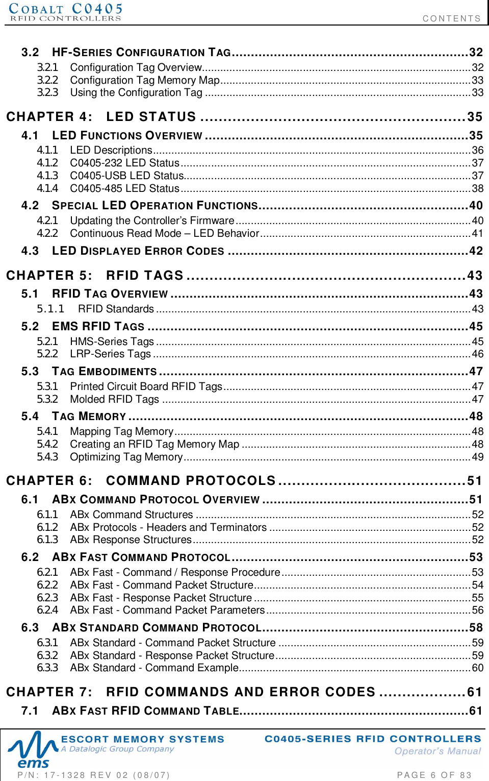
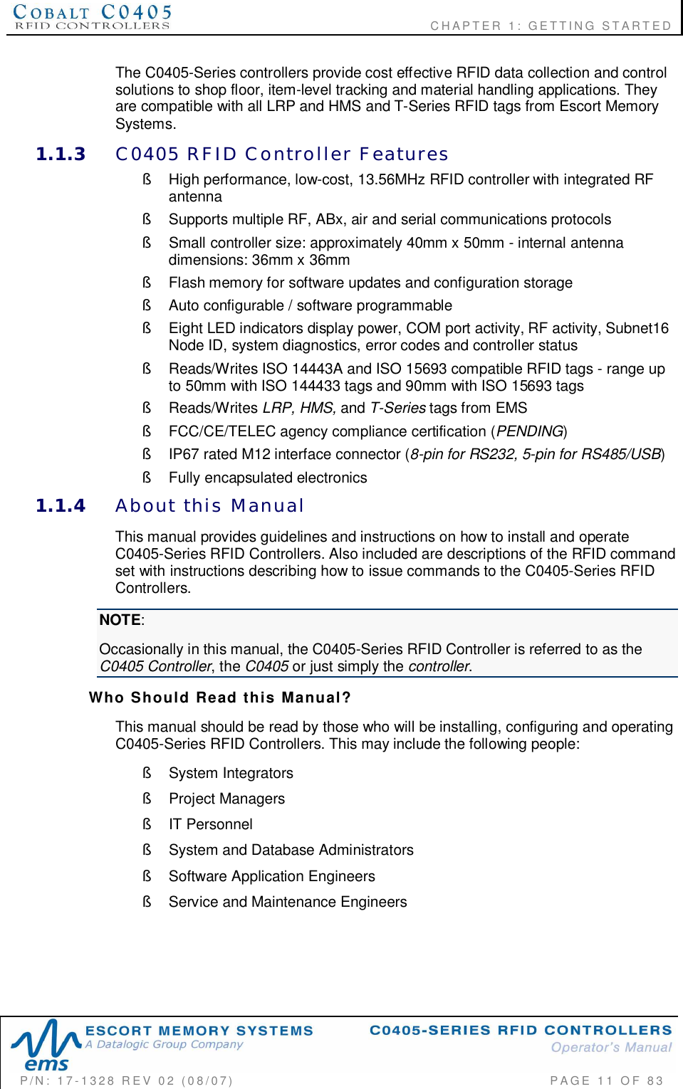
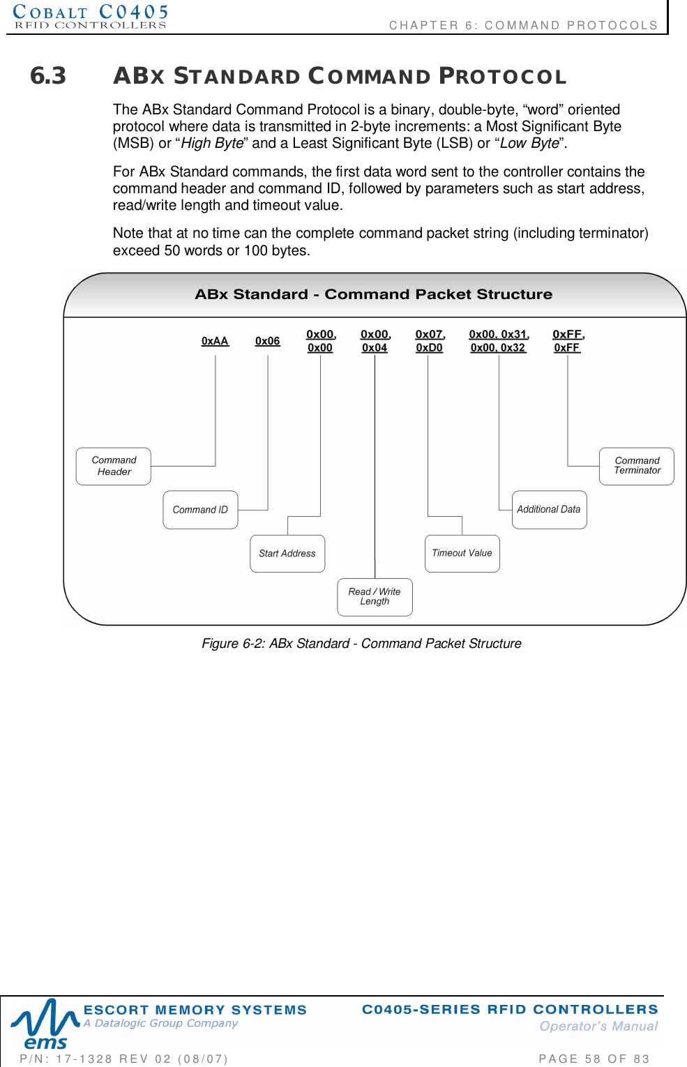
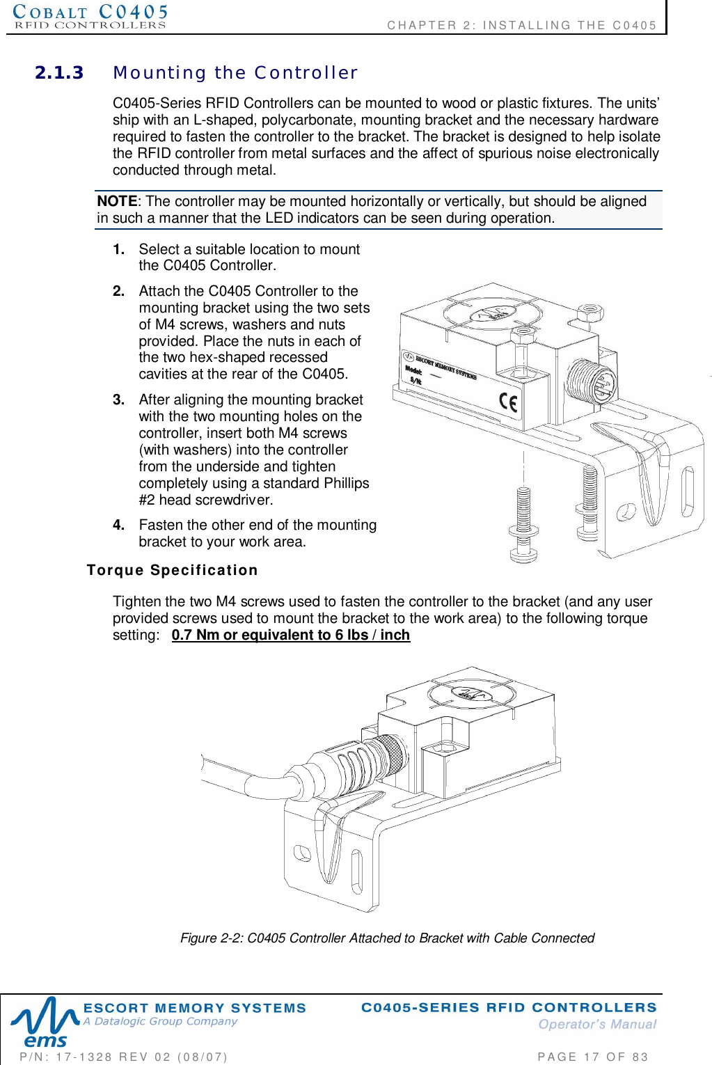
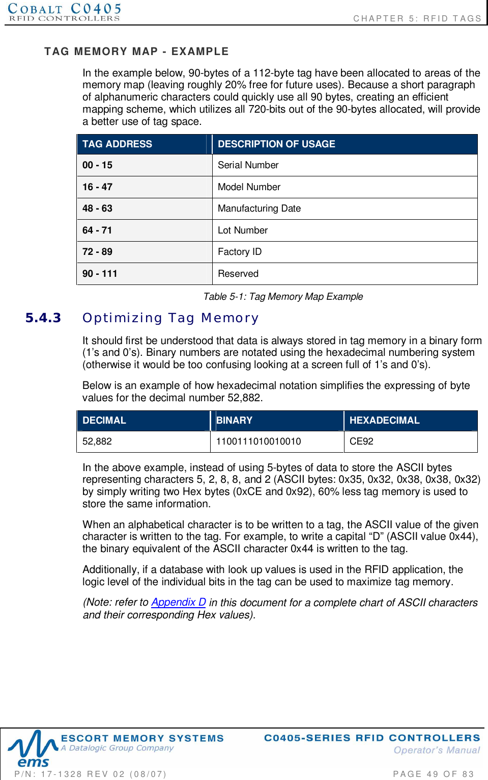
![CHAPTER 2: INSTALLING THE C0405P/N: 17-1328 REV 02 (08/07) PAGE 16 OF 832.1.2 C0405 Controller DimensionsThe images below contain the dimensions of the Cobalt C0405-Series RFIDControllers in millimeters and [inches].Figure 2-1: C0405 RFID Controller Dimensions](https://usermanual.wiki/Balluff/C0405/User-Guide-829582-Page-16.png)
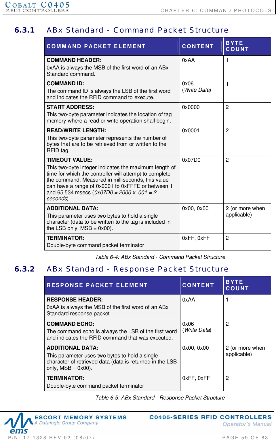
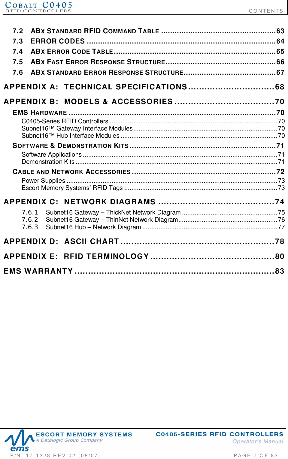
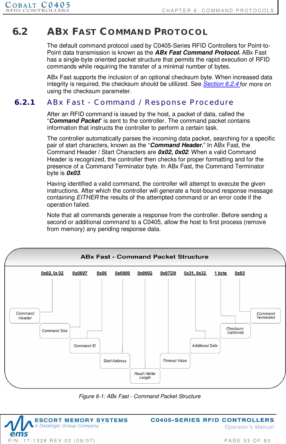
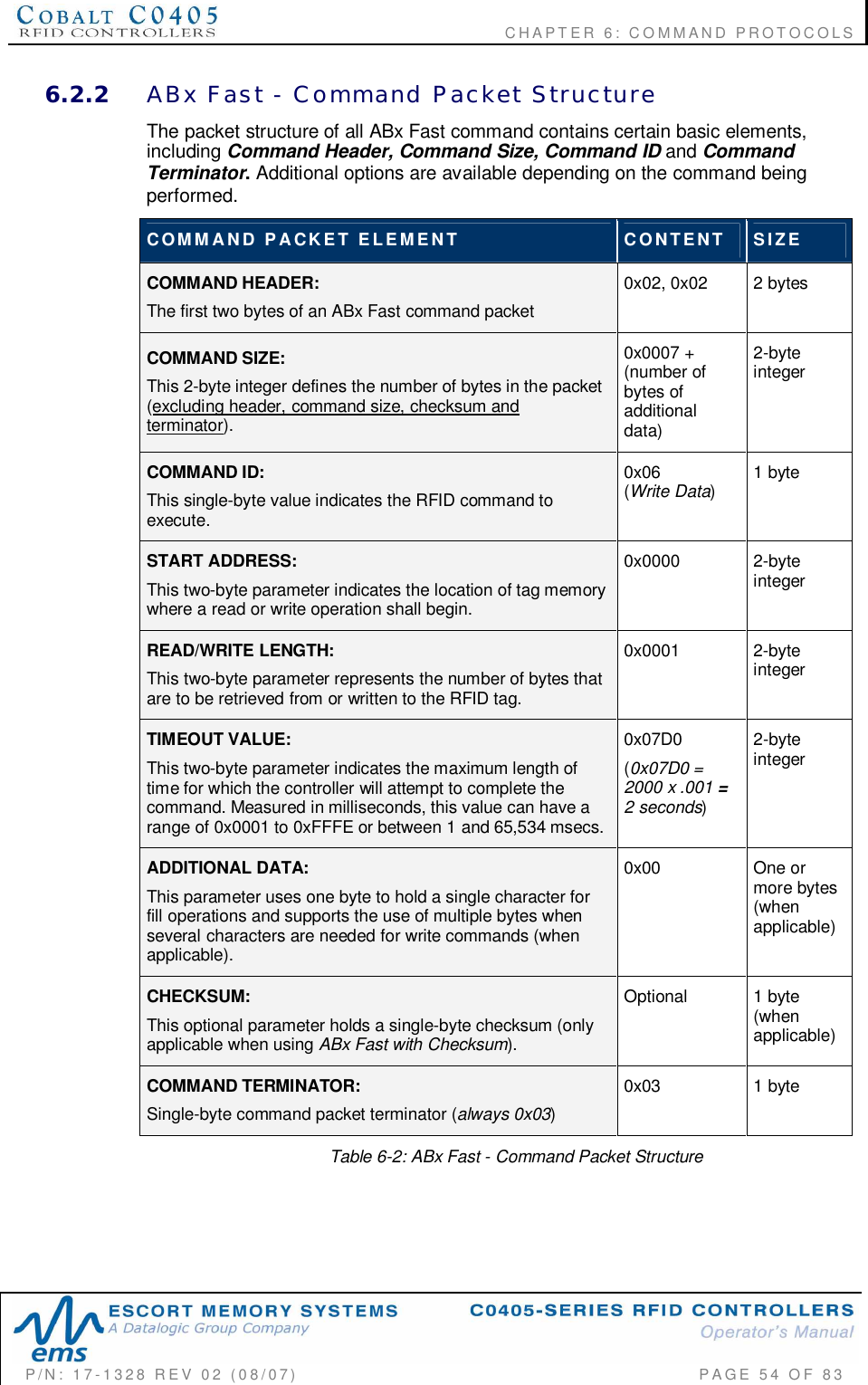
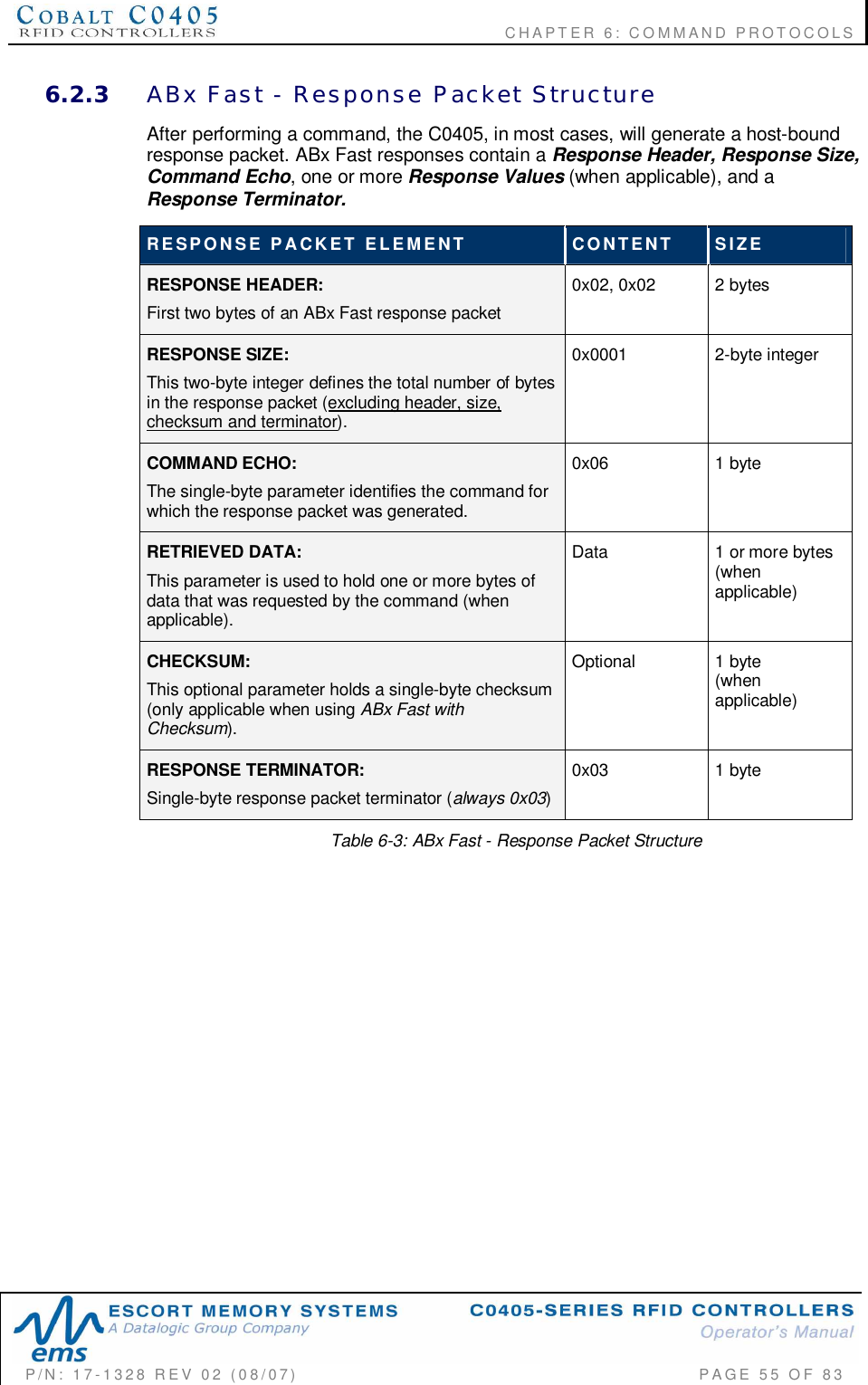
![CHAPTER 6: COMMAND PROTOCOLSP/N: 17-1328 REV 02 (08/07) PAGE 52 OF 836.1.1 ABx Command StructuresAll ABx-based RFID commands contain certain fundamental packet elements,including a Command Header, a Command ID, one or more CommandParameters (when applicable) and a Command Terminator.Command Packet Structure = [Command Header + Command ID + Command Parameters+ Command Terminator]6.1.2 ABx Protocols - Headers and TerminatorsIn ABx Standard, commands begin with the one-byte command header "0xAA," andend with the two-byte command terminator "0xFF, 0xFF".In ABx Fast and ABx ASCII, commands begin with the two-byte command header“0x02, 0x02” and end with the one-byte command terminator “0x03.”See the table below for further clarification.ABx Protocols - Headers and TerminatorsABX PROTOCOL HEADER TERMINATORABx Fast 0x02, 0x02 0x03ABx ASCII 0x02, 0x02 0x03ABx Standard 0xAA 0xFF, 0xFFTable 6-1: ABx Protocols - Headers and TerminatorsWhen a command is issued by the host, the RFID controller stores the incoming datapacket in a buffer while it scans the data for a start character (0x02, 0x02 or 0xAA).When a start character is found, it checks for the proper terminator (0x03 or 0xFF,0xFF). Having identified a potentially valid command string, the controller will verifythe format of the data and either perform the requested function or generate an errormessage.6.1.3 ABx Response StructuresAfter completing an ABx command, the C0405 generates a host-bound, responsepacket that indicates the status and/or results of the attempted command. Theresponse packet structure for all ABx protocols consists of a Response Header, aCommand Echo, one or more Response Values (when applicable), and aResponse Terminator.Response Packet Structure = [Response Header + Command Echo + Response Values +Response Terminator]Note that for each ABx protocol, response header and response terminatorparameters are the same as their command header and command terminatorcounterparts.](https://usermanual.wiki/Balluff/C0405/User-Guide-829582-Page-52.png)
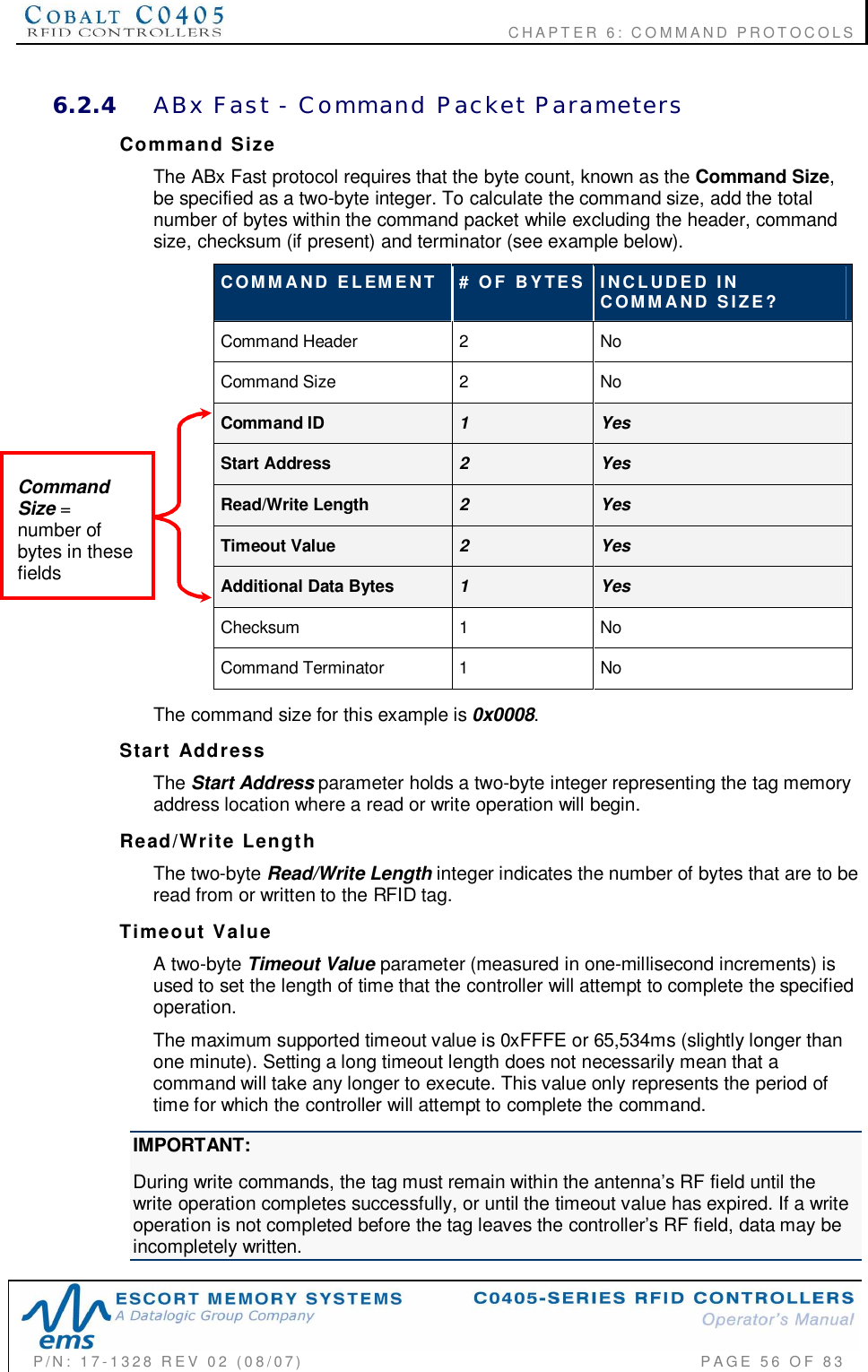
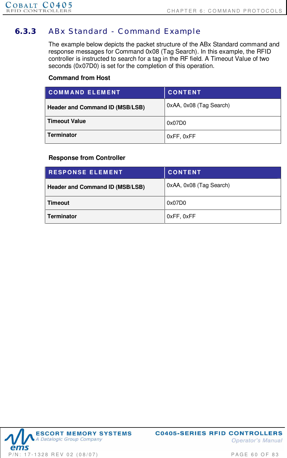
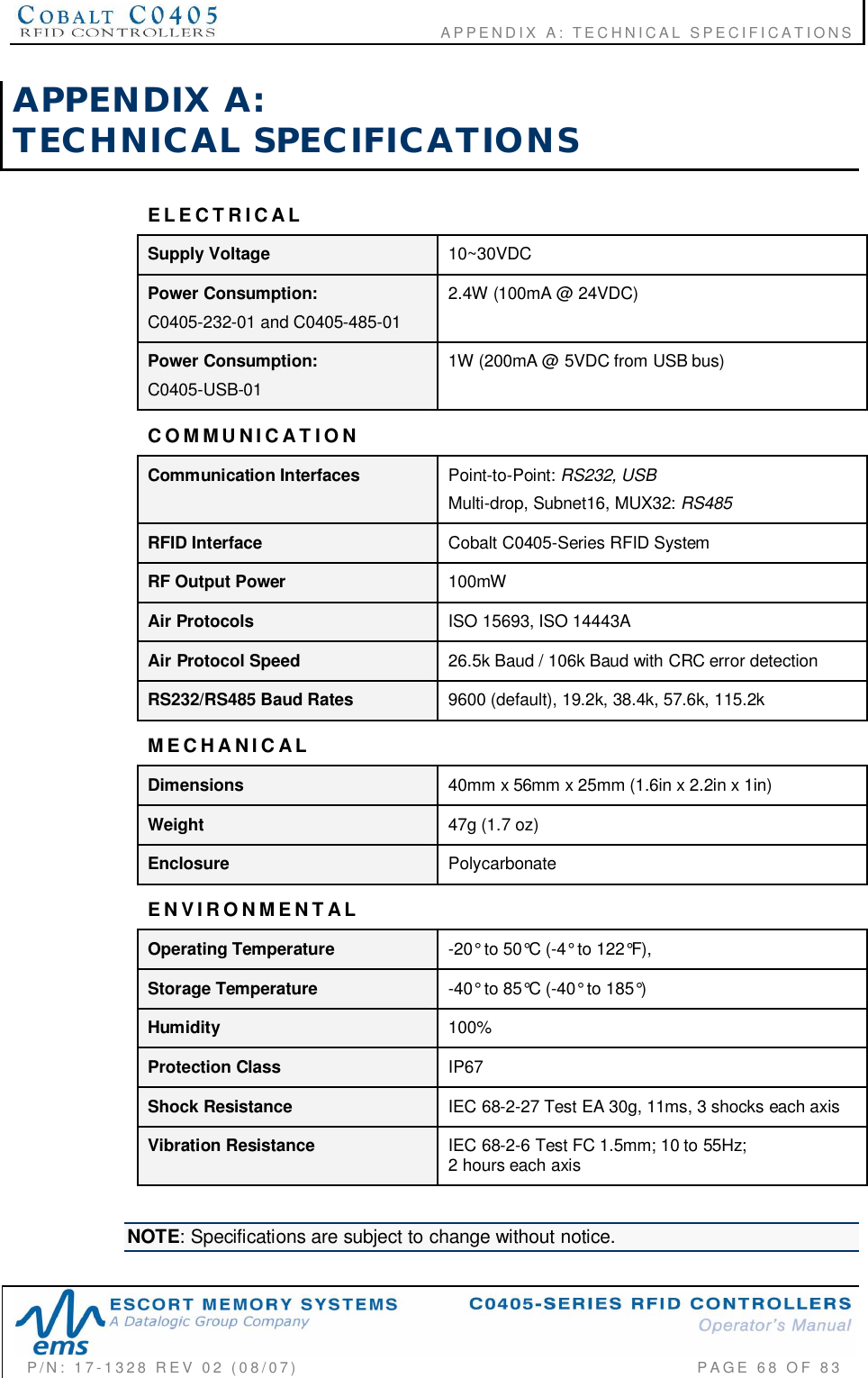
![CHAPTER 6: COMMAND PROTOCOLSP/N: 17-1328 REV 02 (08/07) PAGE 57 OF 83ChecksumABx Fast and ABx ASCII Command Protocols support the inclusion of an additionalchecksum byte that is used to verify the integrity of data being transmitted betweenhost and controller.The checksum is calculated by adding together (summing) the byte values in thecommand packet (less the header, checksum and terminator), and then subtractingthe total byte sum from 0xFF. Therefore, when the byte values of each packetelement (from command size to checksum) are added together, the byte value sumwill equal 0xFF.CHECKSUM EXAMPLEThe following example depicts Command 0x05 (Read Data) using a checksum.COMMANDELEMENT CONTENTS USED IN CHECKSUMCommand Header 0x02, 0x02 n/aCommand Size 0x0007 0x00, 0x07Command ID 0x05 0x05Start Address 0x0001 0x00, 0x01Read Length 0x0004 0x00, 0x04Timeout Value 0x07D0 0x07, 0xD0Checksum 0x17 n/aCommand Terminator 0x03 n/aAdd the byte values from the command size, command ID, start address, read lengthand timeout value parameters together and subtract from 0xFF. Resulting value willbe the checksum.[0x07 + 0x05 + 0x01 + 0x04 + 0x07 + 0xD0] = 0xE8The checksum equation is: [0xFF – 0xE8] = 0x17Checksum =[0xFF – (sumof thesefields)]](https://usermanual.wiki/Balluff/C0405/User-Guide-829582-Page-57.png)